Embed Size (px)
Citation preview
User’sManual
IM 04L51B01-20EN3rd Edition
Model GX10/GX20/GP10/GP20/GM10
OPC-UA Server (/E3)User’s Manual

iIM 04L51B01-20EN
IntroductionThank you for purchasing the SMARTDAC+ GX10/GX20/GP10/GP20 (hereafter referred to as the GX or GP) or the GM.This manual describes the operating procedure for the GX/GP/GM OPC-UA server (/E3 option). Please use this manual in conjunction with the standard user’s manual (IM 04L51B01-01EN (GX/GP) or IM 04L55B01-01EN (GM)).
To ensure correct use, please read this manual thoroughly before beginning operation.The following manuals are provided for the GX/GP/GM.
● PaperManualsModel Manual Title Manual No. DescriptionGX/GP Model GX10/GX20/GP10/GP20
Paperless RecorderFirst Step Guide
IM 04L51B01-02EN Explains the basic operations of the GX/GP.
GM Data Acquisition System GMFirst Step Guide
IM 04L55B01-02EN Explains the basic operations of the GM.
● DownloadableElectronicManualsYou can download the latest manuals from the following website.www.smartdacplus.com/manual/en/
Model Manual Title Manual No. Description
GX/GP Model GX10/GX20/GP10/GP20Paperless Recorder First Step Guide
IM 04L51B01-02EN This is the electronic version of the paper manual.
Model GX10/GX20/GP10/GP20Paperless RecorderUser’s Manual
IM 04L51B01-01EN Describes how to use the GX/GP. The communication control commands and some of the options are excluded.
Model GX10/GX20/GP10/GP20Advanced Security Function (/AS)User’s Manual
IM 04L51B01-05EN Describes how to use the advanced security function (/AS option).
GM GM Data Acquisition SystemFirst Step Guide
IM 04L55B01-02EN This is the electronic version of the paper manual.
GM Data Acquisition SystemUser’s Manual
IM 04L55B01-01EN Describes how to use the GM. The communication control commands and some of the options are excluded.
GM Data Acquisition SystemAdvanced Security Function (/AS)User’s Manual
IM 04L55B01-05EN Describes how to use the advanced security function (/AS option).
GX/GPGM
Model GX10/GX20/GP10/GP20/GM10Communication CommandsUser’s Manual
IM 04L51B01-17EN Describes how to use command control communication functions.
SMARTDAC+ STANDARDUniversal ViewerUser’s Manual
IM 04L61B01-01EN Describes how to use Universal Viewer, which is a software that displays GX/GP/GM measurement data files.
SMARTDAC+ STANDARDHardware ConfiguratorUser’s Manual
IM 04L61B01-02EN Describes how to use the PC software for creating setting parameters for various GX/GP/GM functions.
Model GX10/GX20/GP10/GP20/GM10Multi-batch Function (/BT)User’s Manual
IM 04L51B01-03EN Describes how to use the multi batch function (/BT option).
Model GX10/GX20/GP10/GP20/GM10Log Scale (/LG)User’s Manual
IM 04L51B01-06EN Describes how to use the log scale (/LG option).
Model GX10/GX20/GP10/GP20/GM10EtherNet/IP Communication (/E1)User’s Manual
IM 04L51B01-18EN Describes how to use the communication functions through the EtherNet/IP (/E1 option).
Model GX10/GX20/GP10/GP20/GM10WT Communication (/E2)User’s Manual
IM 04L51B01-19EN Describes how to use WT communication (/E2 option).
Model GX10/GX20/GP10/GP20/GM10OPC-UA Server (/E3)User’s Manual
IM 04L51B01-20EN Describes how to use the OPC-UA server function (/E3 option).
Model GX10/GX20/GP10/GP20/GM10SLMP Communication (/E4)User’s Manual
IM 04L51B01-21EN Describes how to use SLMP communication function (/E3 option).
Model GX10/GX20/GP10/GP20/GM10Loop Control Function, Program Control Function (/PG Option)User’s Manual
IM 04L51B01-31EN Describes how to use the Loop Control Function, Program Control Function (/PG Option).
GX/GP DXA170DAQStudioUser’s Manual
IM 04L41B01-62EN Describes how to create custom displays (/CG option).
3rd Edition: June 2017 (YK)All Rights Reserved, Copyright © 2015, Yokogawa Electric Corporation
ii IM 04L51B01-20EN
Notes● Thecontentsofthismanualaresubjecttochangewithoutpriornoticeasaresultof
continuing improvements to the instrument’s performance and functions.● Everyefforthasbeenmadeinthepreparationofthismanualtoensuretheaccuracyofits
contents. However, should you have any questions or find any errors, please contact your nearest YOKOGAWA dealer.
● CopyingorreproducingalloranypartofthecontentsofthismanualwithoutYOKOGAWA’s permission is strictly prohibited.
Trademarks● SMARTDAC+andSMARTDACPLUSareregisteredtrademarksofYokogawaElectric
Corporation.● MicrosoftandWindowsareregisteredtrademarksortrademarksofMicrosoftCorporation
in the United States and other countries.● AdobeandAcrobatareregisteredtrademarksortrademarksofAdobeSystems
Incorporated.● KerberosisatrademarkofMassachusettsInstituteofTechnology(MIT).● RC4isaregisteredtrademarkofRSASecurityInc.intheUnitedStatesandother
countries.● Companyandproductnamesthatappearinthismanualareregisteredtrademarksor
trademarks of their respective holders.● Thecompanyandproductnamesusedinthismanualarenotaccompaniedbythe
registered trademark or trademark symbols (® and ™).
AbouttheUsageofOpenSourceSoftwareThis product uses open source software.For details on using open source software, see IM 04L61B01-11EN (Regarding the Downloading and Installing for the Software, Manuals and Labels).
RevisionsDecember 2015 1st EditionMarch 2016 2nd EditionJune 2017 3rd Edition
iiiIM 04L51B01-20EN
HowtoUseThisManual
RecorderVersionandFunctionsDescribedinThisManualThe contents of this manual apply to the GX/GP/GM10 with the following release numbers (see the STYLE S number) and style numbers (see the STYLE H number).Model ReleaseNumber StyleNumberGX/GP 4 2GM10 4 1
WhatThisManualExplainsThis manual mainly explains the OPC-UA server. For details on other settings and procedures, see the Model GX10/GX20/GP10/GP20 Paperless Recorder User’s Manual (IM 04L51B01-01EN) or Data Acquisition System GM (IM 04L55B01-01EN).For details on communication commands, see Model GX10/GX20/GP10/GP20/GM10 Communication Command User’s Manual (IM 04L51B01-17EN).
The GX20/GP20/GM10 standard type and large memory type are distinguished using the following notations.•Standardtype: GX20-1/GP20-1/GM10-1•Largememorytype: GX20-2/GP20-2/GM10-2
The following terms are used for references to other manuals:Notation DescriptionGX/GP User’s Manual Model GX10/GX20/GP10/GP20
Paperless Recorder User’s ManualRefers to the IM 04L51B01-01EN.
GX/GP First Step Guide Model GX10/GX20/GP10/GP20Paperless Recorder First Step GuideRefers to the IM 04L51B01-02EN.
GM User’s Manual GM Data Acquisition SystemUser’s ManualRefers to the IM 04L55B01-01EN.
GM First Step Guide GM Data Acquisition SystemFirst Step GuideRefers to the IM 04L55B01-02EN.
Communication Command Manual Model GX10/GX20/GP10/GP20/GM10Communication Command User’s ManualRefers to the IM 04L51B01-17EN.
Universal Viewer Manual SMARTDAC+ STANDARDUniversal Viewer User’s ManualRefers to the IM 04L61B01-01EN.
GX/GP Advanced Security Manual Model GX10/GX20/GP10/GP20Advanced Security Function (/AS) User’s ManualRefers to the IM 04L51B01-05EN.
GM Advanced Security Manual Data Acquisition System GMAdvanced Security Function (/AS) User’s ManualRefers to the IM 04L55B01-05EN.
WT Communication Manual Model GX10/GX20/GP10/GP20/GM10WT Communication (/E2) User’s ManualRefers to the IM 04L51B01-19EN.
SLMP Communication Manual Model GX10/GX20/GP10/GP20/GM10SLMP Communication (/E4) User’s ManualRefers to the IM 04L51B01-21EN.
iv IM 04L51B01-20EN
ConventionsUsedinThisManualUnit
K Denotes 1024. Example: 768K (file size)k Denotes 1000.
NotesImproper handling or use can lead to injury to the user or damage to the instrument. This symbol appears on the instrument to indicate that the user must refer to the user’s manual for special instructions. The same symbol appears in the corresponding place in the user's manual to identify those instructions. In the manual, the symbol is used in conjunction with the word “WARNING” or “CAUTION.”
Warning Calls attention to actions or conditions that could cause serious or fatal injury to the user, and precautions that can be taken to prevent such occurrences.
CAUTION Calls attention to actions or conditions that could cause light injury to the user or cause damage to the instrument or user’s data, and precautions that can be taken to prevent such occurrences.
Note Calls attention to information that is important for the proper operation of the instrument.
ReferenceItemReference to related operation or explanation is indicated after this mark.Example: section 4.1
ConventionsUsedintheProceduralExplanationsBoldcharacters Denotes key or character strings that appear on the screen.
Example: Voltage
A a # 1 Indicates the character types that can be used.
Procedure Carry out the procedure according to the step numbers. All procedures are written with inexperienced users in mind; depending on the operation, not all steps need to be taken.Explanation gives information such as limitations related the procedure.
Indicates the setup screen and explains the settings.
Explanation
Path
Description
How to Use This Manual
vIM 04L51B01-20EN
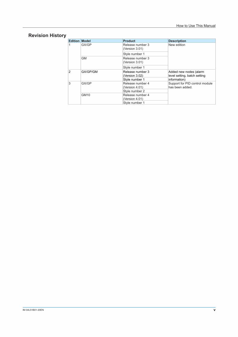
Revision HistoryEdition Model Product Description1 GX/GP Release number 3
(Version 3.01)New edition
Style number 1GM Release number 3
(Version 3.01)Style number 1
2 GX/GP/GM Release number 3(Version 3.02)
Added new nodes (alarm level setting, batch setting information)Style number 1
3 GX/GP Release number 4(Version 4.01)
Support for PID control module has been added.
Style number 2GM10 Release number 4
(Version 4.01)Style number 1
How to Use This Manual
vi IM 04L51B01-20EN
Contents
Introduction ................................................................................................................................................ iNotes ........................................................................................................................................................ iiTrademarks .............................................................................................................................................. iiRevisions .................................................................................................................................................. ii
How to Use This Manual ......................................................................................................................iiiRecorder Version and Functions Described in This Manual .....................................................................iiiWhat This Manual Explains ......................................................................................................................iiiConventions Used in This Manual ........................................................................................................... ivRevision History........................................................................................................................................ v
Introduction of Features ....................................................................................................................1-1Overview................................................................................................................................................1-1
OPC-UA Server (/E3) Specifications ................................................................................................1-2Communication Specifications ..............................................................................................................1-2Security..................................................................................................................................................1-3
GX/GP/GM Configuration .................................................................................................................1-5OPC-UA Server Function ......................................................................................................................1-5Others ....................................................................................................................................................1-5
GX/GP/GM Data Structure ...............................................................................................................1-6Entire Structure......................................................................................................................................1-6List of Nodes..........................................................................................................................................1-7Communication Channel Description ....................................................................................................1-8I/O Channel Description ........................................................................................................................1-9Math Channel Description ...................................................................................................................1-10PID Control Channel Description......................................................................................................... 1-11Device Description...............................................................................................................................1-12
OPC-UA Communication Data .......................................................................................................1-13Handling of Communication Data ........................................................................................................1-13
Subscription Operation ...................................................................................................................1-14
1-1IM 04L51B01-20EN
IntroductionofFeatures
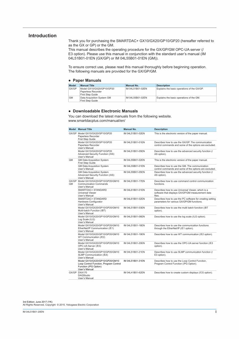
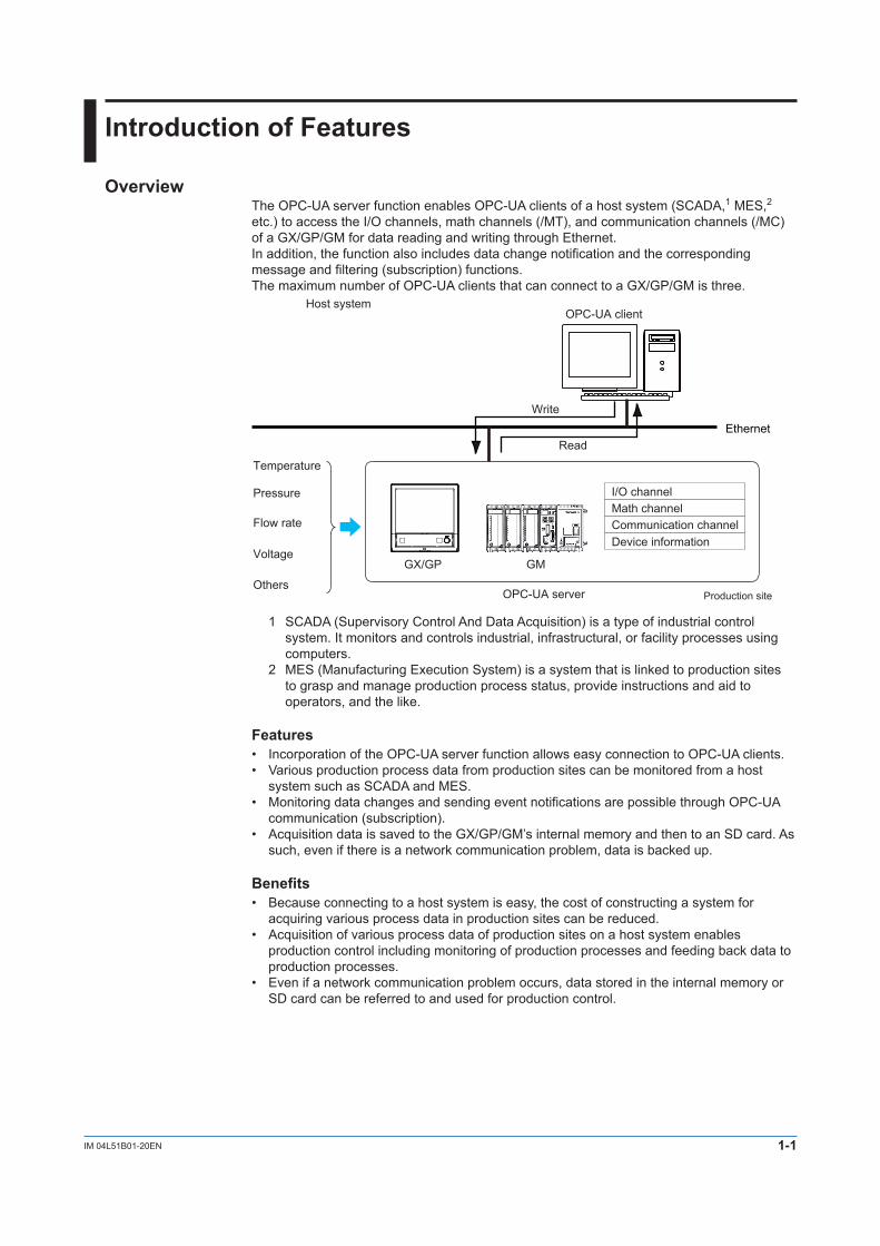
OverviewThe OPC-UA server function enables OPC-UA clients of a host system (SCADA,1 MES,2 etc.) to access the I/O channels, math channels (/MT), and communication channels (/MC) of a GX/GP/GM for data reading and writing through Ethernet.In addition, the function also includes data change notification and the corresponding message and filtering (subscription) functions.The maximum number of OPC-UA clients that can connect to a GX/GP/GM is three.
GX/GP GM
Ethernet
OPC-UA server
OPC-UA clientHost system
Production site
Temperature
Pressure
Flow rate
Read
Write
Voltage
Others
I/O channelMath channelCommunication channelDevice information
1 SCADA (Supervisory Control And Data Acquisition) is a type of industrial control system. It monitors and controls industrial, infrastructural, or facility processes using computers.
2 MES (Manufacturing Execution System) is a system that is linked to production sites to grasp and manage production process status, provide instructions and aid to operators, and the like.
Features• IncorporationoftheOPC-UAserverfunctionallowseasyconnectiontoOPC-UAclients.• Variousproductionprocessdatafromproductionsitescanbemonitoredfromahost
system such as SCADA and MES.• MonitoringdatachangesandsendingeventnotificationsarepossiblethroughOPC-UA
communication (subscription).• AcquisitiondataissavedtotheGX/GP/GM’sinternalmemoryandthentoanSDcard.As
such, even if there is a network communication problem, data is backed up.
Benefits• Becauseconnectingtoahostsystemiseasy,thecostofconstructingasystemfor
acquiring various process data in production sites can be reduced.• Acquisitionofvariousprocessdataofproductionsitesonahostsystemenables
production control including monitoring of production processes and feeding back data to production processes.
• Evenifanetworkcommunicationproblemoccurs,datastoredintheinternalmemoryorSD card can be referred to and used for production control.
1-2 IM 04L51B01-20EN
OPC-UAServer(/E3)Specifications
CommunicationSpecificationsThe following table shows the communication specifications of the GX/GP/GM OPC-UA server.Group SubGroup SupportedFunctionCommunication Type Server
Encoding UA BinaryProtocol OPC UA TCPPort number 4840/tcp (depends on the setting)Maximum number of client connections
3 (Max 3 sessions)
Language Supported language EnglishSecurity Mode None
Encryption NoneLogin Anonymous
UserNameFunction Server type Data Access Server (DA)
Profile Micro Embedded Device ServerMaximum number of items GX20/GP20/GM10: 300 (MonitoredItem/Session)
GX10/GP10: 100 (MonitoredItem/Session)Maximum number of subscriptions
3/session
Fastest period 100 ms (Publish Interval)Supported services
Discovery FindServersGetEndpoints
SecureChannel OpenSecureChannelCloseSecureChannel
Session CreateSessionActivateSessionCloseSession
View BrowseBrowseNextTranslateBrowsePathsToNodeIds
Attribute ReadWrite
MonitoredItem CreateMonitoredItemsModifyMonitoredItemsDeleteMonitoredItemsSetMonitoringMode
Subscription CreateSubscriptionModifySubscriptionDeleteSubscriptionsPublishRepublishSetPublishingMode
1-3IM 04L51B01-20EN
SecurityThis section explains the security features of the GX/GP/GM OPC-UA server.
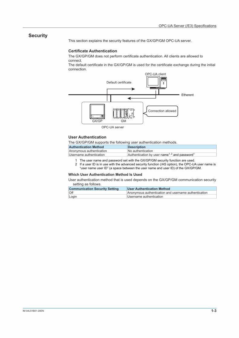
CertificateAuthenticationThe GX/GP/GM does not perform certificate authentication. All clients are allowed to connect.The default certificate in the GX/GP/GM is used for the certificate exchange during the initial connection.
GX/GP GM
Default certificate
OPC-UA client
Etherent
OPC-UA server
Connection allowed
UserAuthenticationThe GX/GP/GM supports the following user authentication methods.AuthenticationMethod DescriptionAnonymous authentication No authenticationUsername authentication Authentication by user name1, 2 and password1
1 The user name and password set with the GX/GP/GM security function are used.2 If a user ID is in use with the advanced security function (/AS option), the OPC-UA user name is
“user name user ID” (a space between the user name and user ID) of the GX/GP/GM.
WhichUserAuthenticationMethodIsUsedUser authentication method that is used depends on the GX/GP/GM communication security
setting as follows.CommunicationSecuritySetting UserAuthenticationMethodOff Anonymous authentication and username authenticationLogin Username authentication
OPC-UA Server (/E3) Specifications
1-4 IM 04L51B01-20EN
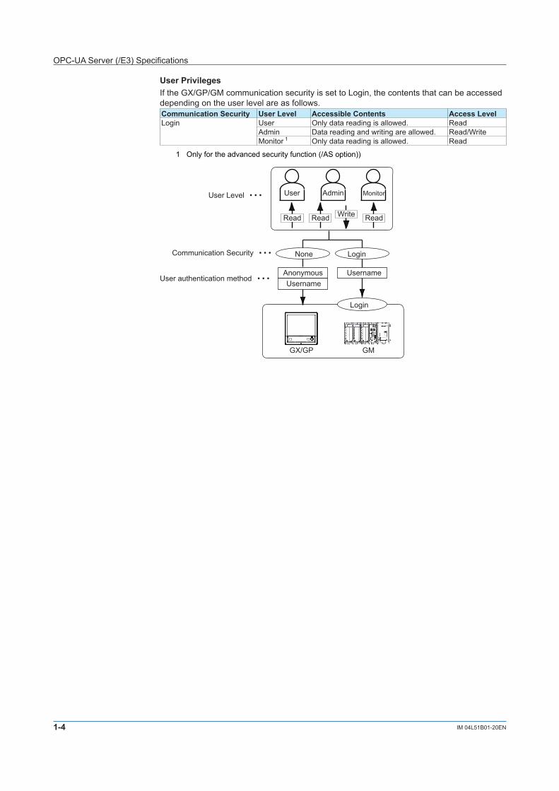
UserPrivilegesIf the GX/GP/GM communication security is set to Login, the contents that can be accessed depending on the user level are as follows.Communication Security User Level AccessibleContents Access LevelLogin User Only data reading is allowed. Read
Admin Data reading and writing are allowed. Read/WriteMonitor 1 Only data reading is allowed. Read
1 Only for the advanced security function (/AS option))
GX/GP GM
AdminUser Level
None Login
UsernameAnonymous Username
User authentication method
Communication Security
User
WriteReadRead
Login
• • •
• • •
• • •
Monitor
Read
OPC-UA Server (/E3) Specifications
1-5IM 04L51B01-20EN
GX/GP/GMConfiguration
OPC-UA Server Function
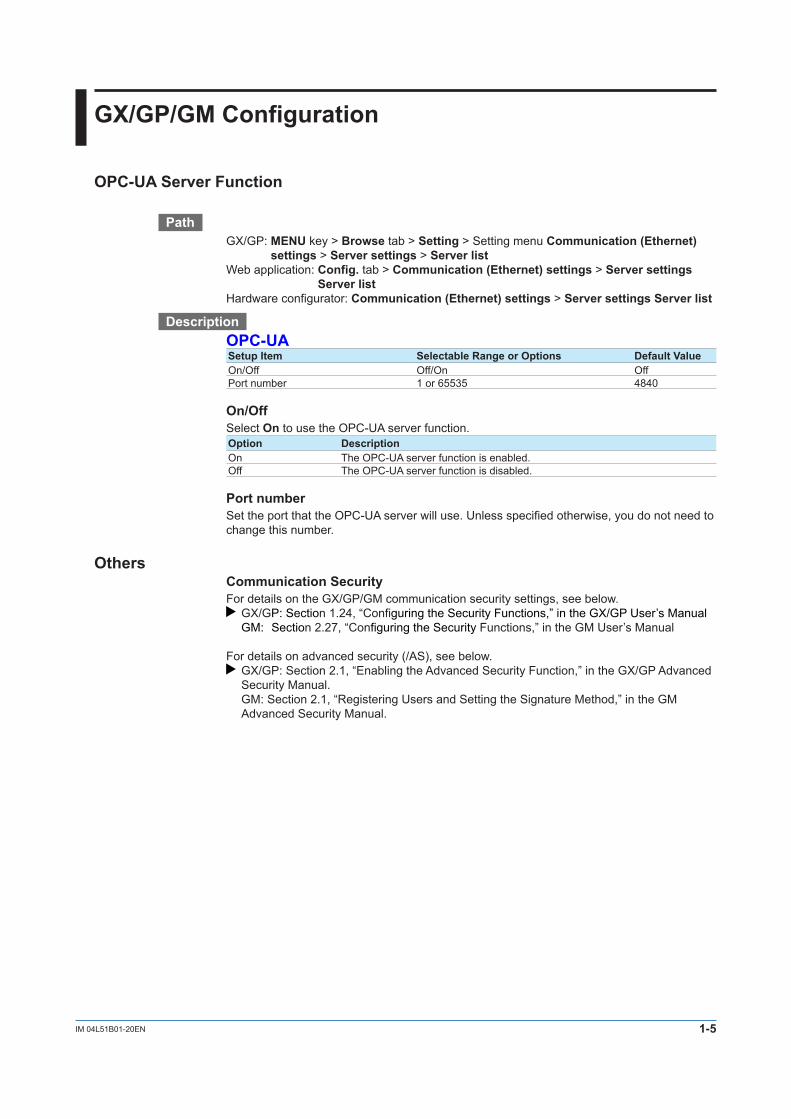
PathGX/GP: MENU key > Browse tab > Setting > Setting menu Communication(Ethernet)
settings > Serversettings > Server listWeb application: Config. tab > Communication(Ethernet)settings > Serversettings
Server listHardware configurator: Communication(Ethernet)settings > ServersettingsServerlist
DescriptionOPC-UASetupItem SelectableRangeorOptions DefaultValueOn/Off Off/On OffPort number 1 or 65535 4840
On/OffSelect On to use the OPC-UA server function.Option DescriptionOn The OPC-UA server function is enabled.Off The OPC-UA server function is disabled.
PortnumberSet the port that the OPC-UA server will use. Unless specified otherwise, you do not need to change this number.
OthersCommunication SecurityFor details on the GX/GP/GM communication security settings, see below.
GX/GP: Section 1.24, “Configuring the Security Functions,” in the GX/GP User’s Manual GM: Section 2.27, “Configuring the Security Functions,” in the GM User’s Manual
For details on advanced security (/AS), see below. GX/GP: Section 2.1, “Enabling the Advanced Security Function,” in the GX/GP Advanced Security Manual.
GM: Section 2.1, “Registering Users and Setting the Signature Method,” in the GM Advanced Security Manual.
1-6 IM 04L51B01-20EN
GX/GP/GM Data Structure
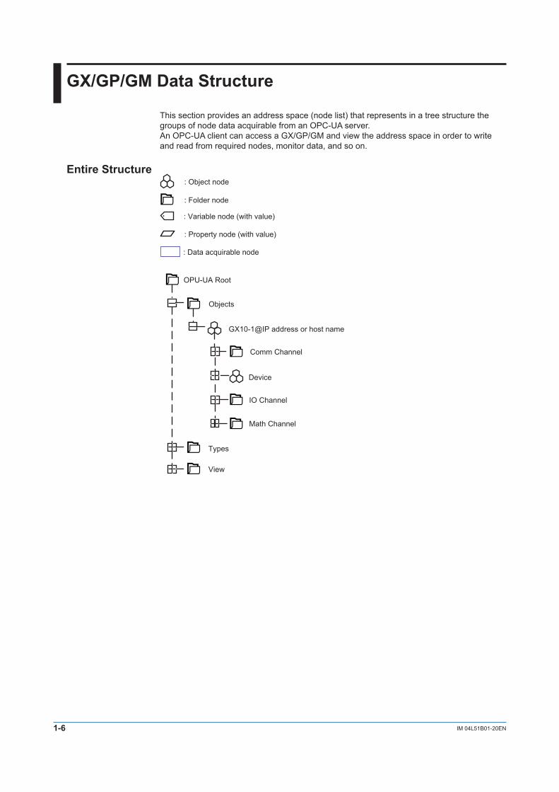
This section provides an address space (node list) that represents in a tree structure the groups of node data acquirable from an OPC-UA server.An OPC-UA client can access a GX/GP/GM and view the address space in order to write and read from required nodes, monitor data, and so on.
Entire Structure
Device
GX10-1@IP address or host name
Objects
IO Channel
Math Channel
OPU-UA Root
Comm Channel
Types
View
: Object node
: Folder node
: Variable node (with value)
: Property node (with value)
: Data acquirable node
1-7IM 04L51B01-20EN
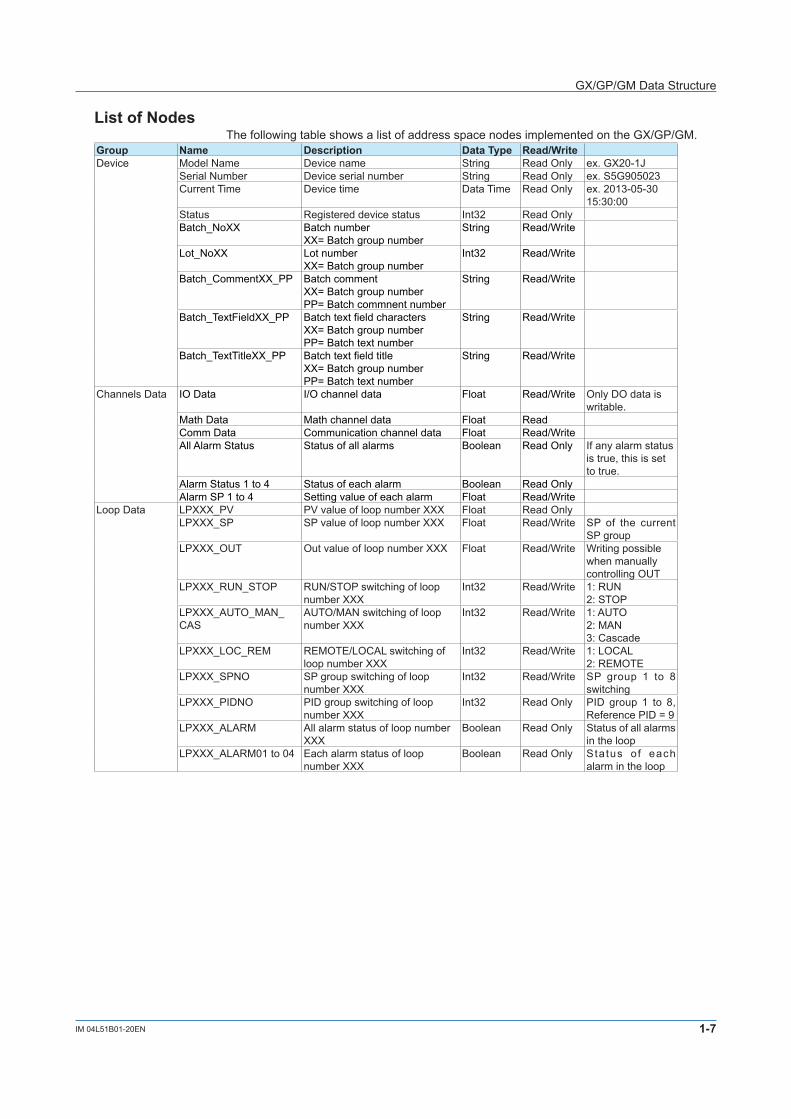
ListofNodesThe following table shows a list of address space nodes implemented on the GX/GP/GM.
Group Name Description DataType Read/WriteDevice Model Name Device name String Read Only ex. GX20-1J
Serial Number Device serial number String Read Only ex. S5G905023Current Time Device time Data Time Read Only ex. 2013-05-30
15:30:00Status Registered device status Int32 Read OnlyBatch_NoXX Batch number
XX= Batch group numberString Read/Write
Lot_NoXX Lot numberXX= Batch group number
Int32 Read/Write
Batch_CommentXX_PP Batch commentXX= Batch group numberPP= Batch commnent number
String Read/Write
Batch_TextFieldXX_PP Batch text field charactersXX= Batch group numberPP= Batch text number
String Read/Write
Batch_TextTitleXX_PP Batch text field titleXX= Batch group numberPP= Batch text number
String Read/Write
Channels Data IO Data I/O channel data Float Read/Write Only DO data is writable.
Math Data Math channel data Float ReadComm Data Communication channel data Float Read/WriteAll Alarm Status Status of all alarms Boolean Read Only If any alarm status
is true, this is set to true.
Alarm Status 1 to 4 Status of each alarm Boolean Read OnlyAlarm SP 1 to 4 Setting value of each alarm Float Read/Write
Loop Data LPXXX_PV PV value of loop number XXX Float Read OnlyLPXXX_SP SP value of loop number XXX Float Read/Write SP of the current
SP groupLPXXX_OUT Out value of loop number XXX Float Read/Write Writing possible
when manually controlling OUT
LPXXX_RUN_STOP RUN/STOP switching of loop number XXX
Int32 Read/Write 1: RUN2: STOP
LPXXX_AUTO_MAN_CAS
AUTO/MAN switching of loop number XXX
Int32 Read/Write 1: AUTO2: MAN3: Cascade
LPXXX_LOC_REM REMOTE/LOCAL switching of loop number XXX
Int32 Read/Write 1: LOCAL2: REMOTE
LPXXX_SPNO SP group switching of loop number XXX
Int32 Read/Write SP group 1 to 8 switching
LPXXX_PIDNO PID group switching of loop number XXX
Int32 Read Only PID group 1 to 8, Reference PID = 9
LPXXX_ALARM All alarm status of loop number XXX
Boolean Read Only Status of all alarms in the loop
LPXXX_ALARM01 to 04 Each alarm status of loop number XXX
Boolean Read Only Status of each alarm in the loop
GX/GP/GM Data Structure
1-8 IM 04L51B01-20EN
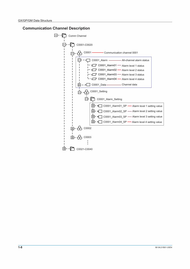
CommunicationChannelDescription
C0001
C0001_Alarm01
C0001_Alarm02
C0001_Alarm03
C0001-C0020
C0001_Alarm
Comm Channel
C0001_Alarm04
C0001_Data
C0002
C0003
• • •
C0021-C0040
Communication channel 0001
All-channel alarm status
Alarm level 1 status
Alarm level 2 status
Alarm level 3 status
Alarm level 4 status
Channel data
C0001_Setting
C0001_Alarm_Setting
C0001_Alarm01_SP
C0001_Alarm02_SP
Alarm level 1 setting value
C0001_Alarm03_SP
C0001_Alarm04_SP
Alarm level 2 setting value
Alarm level 3 setting value
Alarm level 4 setting value
GX/GP/GM Data Structure
1-9IM 04L51B01-20EN
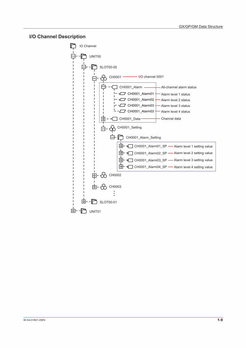
I/OChannelDescription
CH0001
CH0001_Alarm01
CH0001_Alarm02
CH0001_Alarm03
SLOT00-00
CH0001_Alarm
UNIT00
CH0001_Alarm03
CH0001_Data
CH0002
CH0003
• • •
SLOT00-01
UNIT01
IO Channel
I/O channel 0001
All-channel alarm status
Alarm level 1 status
Alarm level 2 status
Alarm level 3 status
Alarm level 4 status
Channel data
CH0001_Setting
CH0001_Alarm_Setting
CH0001_Alarm01_SP
CH0001_Alarm02_SP
Alarm level 1 setting value
CH0001_Alarm03_SP
CH0001_Alarm04_SP
Alarm level 2 setting value
Alarm level 3 setting value
Alarm level 4 setting value
GX/GP/GM Data Structure
1-10 IM 04L51B01-20EN
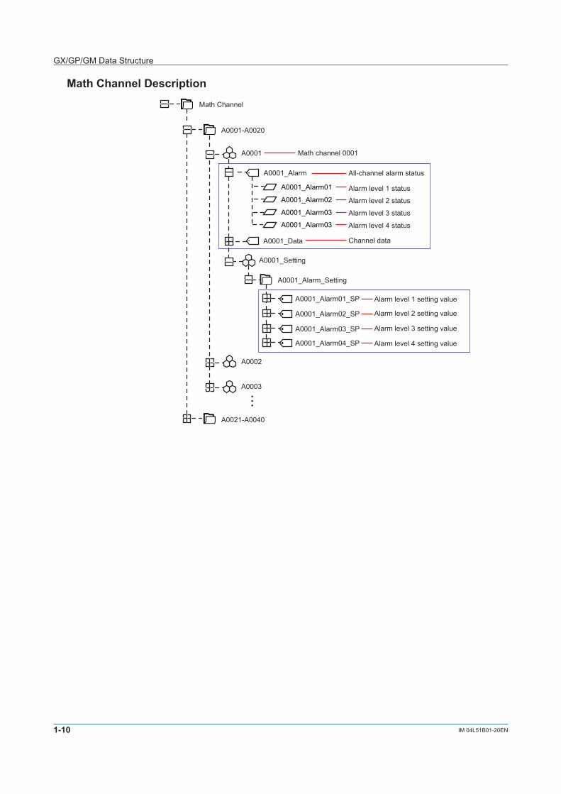
MathChannelDescription
A0001
A0001_Alarm01
A0001_Alarm02
A0001_Alarm03
A0001-A0020
A0001_Alarm
Math Channel
A0001_Alarm03
A0001_Data
A0002
A0003
• • •
A0021-A0040
Math channel 0001
All-channel alarm status
Alarm level 1 status
Alarm level 2 status
Alarm level 3 status
Alarm level 4 status
Channel data
A0001_Setting
A0001_Alarm_Setting
A0001_Alarm01_SP
A0001_Alarm02_SP
Alarm level 1 setting value
A0001_Alarm03_SP
A0001_Alarm04_SP
Alarm level 2 setting value
Alarm level 3 setting value
Alarm level 4 setting value
GX/GP/GM Data Structure
1-11IM 04L51B01-20EN
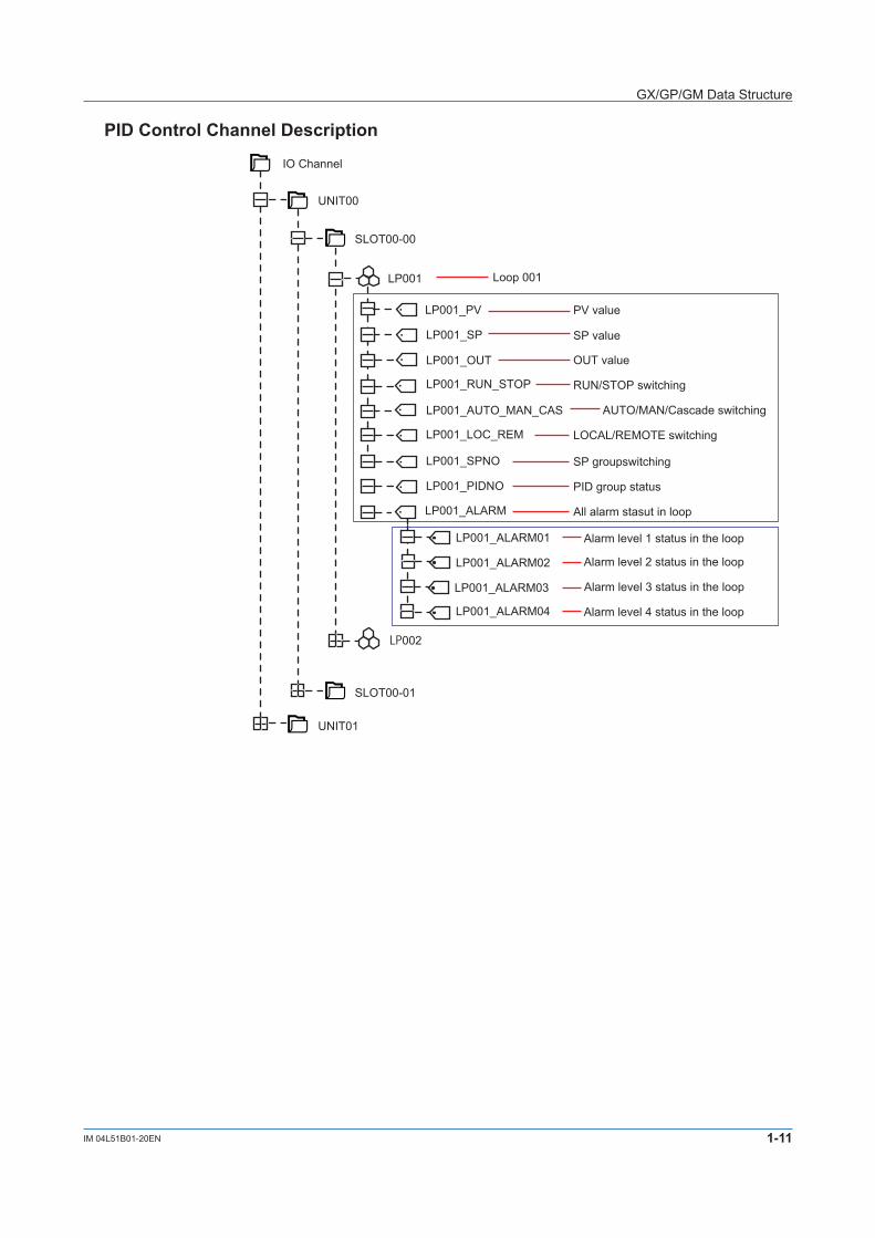
PIDControlChannelDescription
LP001
LP001_SP
LP001_OUT
LP001_RUN_STOP
SLOT00-00
LP001_PV
UNIT00
LP001_AUTO_MAN_CAS
LP001_LOC_REM
LP002
SLOT00-01
UNIT01
IO Channel
Loop 001
PV value
SP value
OUT value
RUN/STOP switching
AUTO/MAN/Cascade switching
LOCAL/REMOTE switching
LP001_ALARM
LP001_ALARM01
LP001_ALARM02
Alarm level 1 status in the loop
LP001_ALARM03
LP001_ALARM04
Alarm level 2 status in the loop
Alarm level 3 status in the loop
Alarm level 4 status in the loop
All alarm stasut in loop
LP001_SPNO SP groupswitching
LP001_PIDNO PID group status
GX/GP/GM Data Structure
1-12 IM 04L51B01-20EN
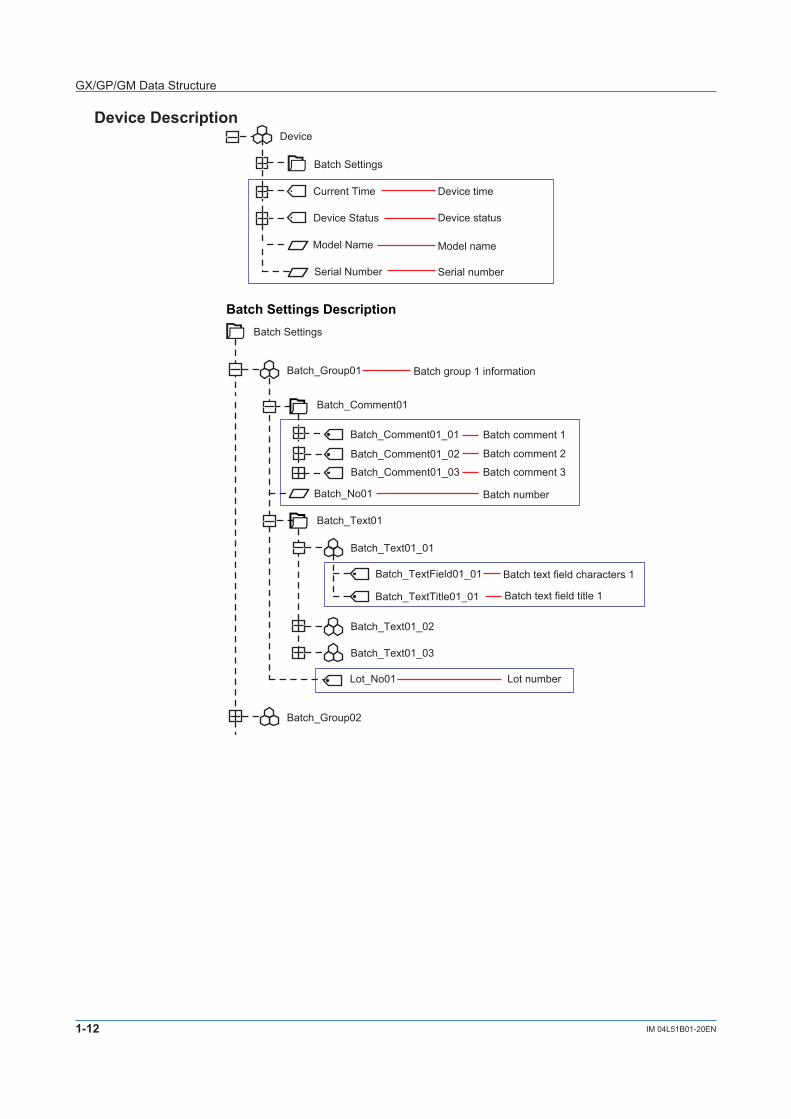
DeviceDescription
Device
Model Name
Serial Number
Current Time
Device Status
Device time
Device status
Model name
Serial number
Batch Settings
BatchSettingsDescription
Batch_Comment01
Batch_Comment01_02
Batch_Comment01_03
Batch_No01
Batch_Group01
Batch_Comment01_01
Batch Settings
Batch comment 1
Batch comment 2
Batch comment 3
Batch number
Batch_Text01_01
Batch_TextField01_01
Batch_TextTitle01_01
Batch text field characters 1
Lot_No01
Batch text field title 1
Lot number
Batch group 1 information
Batch_Text01
Batch_Text01_02
Batch_Text01_03
Batch_Group02
GX/GP/GM Data Structure
1-13IM 04L51B01-20EN
OPC-UA Communication Data
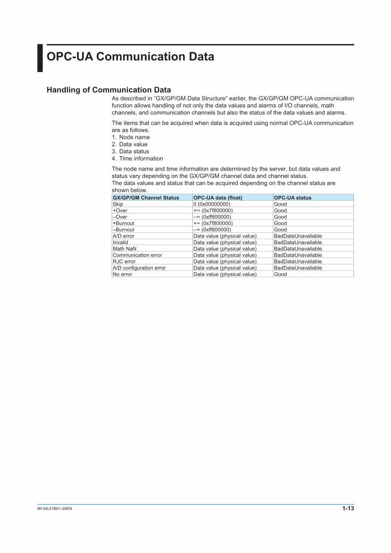
HandlingofCommunicationDataAs described in “GX/GP/GM Data Structure” earlier, the GX/GP/GM OPC-UA communication function allows handling of not only the data values and alarms of I/O channels, math channels, and communication channels but also the status of the data values and alarms.
The items that can be acquired when data is acquired using normal OPC-UA communication are as follows.1. Node name2. Data value3. Data status4. Time information
The node name and time information are determined by the server, but data values and status vary depending on the GX/GP/GM channel data and channel status.The data values and status that can be acquired depending on the channel status are shown below.GX/GP/GMChannelStatus OPC-UAdata(float) OPC-UA statusSkip 0 (0x00000000) Good+Over +∞(0x7f800000) Good–Over –∞(0xff800000) Good+Burnout +∞(0x7f800000) Good–Burnout –∞(0xff800000) GoodA/D error Data value (physical value) BadDataUnavailableInvalid Data value (physical value) BadDataUnavailableMath NaN Data value (physical value) BadDataUnavailableCommunication error Data value (physical value) BadDataUnavailableRJC error Data value (physical value) BadDataUnavailableA/D configuration error Data value (physical value) BadDataUnavailableNo error Data value (physical value) Good
1-14 IM 04L51B01-20EN
SubscriptionOperation
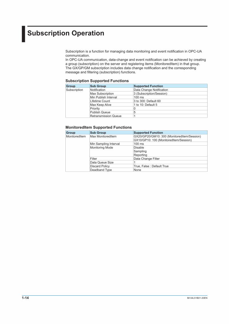
Subscription is a function for managing data monitoring and event notification in OPC-UA communication.In OPC-UA communication, data-change and event notification can be achieved by creating a group (subscription) on the server and registering items (MonitoredItem) in that group.The GX/GP/GM subscription includes data change notification and the corresponding message and filtering (subscription) functions.
SubscriptionSupportedFunctionsGroup SubGroup SupportedFunctionSubscription Notification Data Change Notification
Max Subscription 3 (Subscription/Session)Min Publish Interval 100 msLifetime Count 3 to 300: Default 60Max Keep Alive 1 to 10: Default 5Priority 0Publish Queue 5Retransmission Queue 1
MonitoredItemSupportedFunctionsGroup SubGroup SupportedFunctionMonitoredItem Max MonitoredItem GX20/GP20/GM10: 300 (MonitoredItem/Session)
GX10/GP10: 100 (MonitoredItem/Session) Min Sampling Interval 100 msMonitoring Mode Disable
SamplingReporting
Filter Data Change FilterData Queue Size 1Discard Policy True, False : Default TrueDeadband Type None


![Handbuch TC3 OPC UA - Beckhoff Automation · OPC UA Sample Client [Grafische Beispielimplementierung eines OPC UA} 206] Clients um einen ersten Verbindungstest mit dem TwinCAT OPC](https://img.pdfslide.net/doc/110x75/5f0687177e708231d4186f52/handbuch-tc3-opc-ua-beckhoff-automation-opc-ua-sample-client-grafische-beispielimplementierung.jpg)