Embed Size (px)
Citation preview
The Open Transport Phenomena Journal, 2011, 3, 17-30 17
1877-7295/11 2011 Bentham Open
Open Access
Gas-Liquid Flow Distributions in Multipass Channels with Vertical Upward Branches
Zuradzman bin Mohamad Razlan1, Hiroaki Goshima1, Masafumi Hirota*,1, Ryota Isobe2, Yasuhiro Mizuno3, Naoki Maruyama1 and Akira Nishimura1
1Department of Mechanical Engineering, Mie University, 1577 Kurimamachiya-cho, Tsu-city 514-8507, Japan 2Hamaoka Nuclear Power Station, Chubu Electric Power, 5561 Sakura, Omaezaki, Shizuoka 437-1604, Japan 3DENSO CORPORATION, 1-1 Showa-cho, Kariya 448-8661, Japan
Abstract: The gas-liquid flow distributions in multi-pass channels that simulate a compact evaporator used for an automobile air-conditioning system was examined experimentally. The test channel had a horizontal header with a square cross section of 20mm × 20mm and a length of 255mm, and ten upward branches with a length of 200mm were connected to it. Experiments were conducted in an isothermal air-water flow system. Special attention was directed to influences of (i) flow-inlet condition at the header entrance (stratified-flow inlet and mist-flow inlet), (ii) pressure condition at the branch outlets (uniform backpressure and non-uniform backpressure) and (iii) pressure-loss characteristics of branches (flat tubes and multi-port tubes) on the gas-liquid distribution characteristics. In addition to the gas-liquid distributions to branches, the pressure distributions in the headers were measured to make clear the pressure condition in a real evaporator. It was found that the outlet pressure condition of branches exerts great influence on the gas-liquid distributions to branches in the channel with flat tube branches, but it has only minor influence in the channel with multi-port tube branches. The flow-inlet condition at the header entrance has significant influence on the gas-liquid distribution, and the uniformity of the liquid distribution to branches is improved under the mist-flow inlet condition. The pressure in the headers showed uniform distributions in the longitudinal direction, suggesting that the uniform backpressure condition at the branch outlets is appropriate for reproducing the flow in a real compact evaporator with multi-pass channels.
Keywords: Gas-liquid flow, flow distribution, multi-pass channel, multi-port tube, flow pattern, pressure distribution.
1. INTRODUCTION
In compact evaporators used in an automobile air- conditioning system, the multi-pass channels with parallel flow circuit are often used to improve their thermal per-formance and compactness [1]. It is known that the mal-distribution of gas and liquid from the dividing header to the branches (refrigerant tubes) often occurs in those multi-flow type evaporators, and in extreme cases no liquid is provided to some branches. The thermal performance of the evapo-rator is greatly affected by the flow distribution charac-teristics of the multi-pass channel, and a uniform distribution of liquid to all the branches is desirable to the evaporator. Therefore, the two-phase flow distribution in multi-pass channels has been a major problem in development of compact heat exchangers, and many studies have been conducted on this subject in real refrigerant flow system [2-9] or in isothermal air-water flow system [10-17]. Recently, an extensive review of researches on the gas-liquid flow distributions in T-junctions and multi-pass channels was published by Lee et al. [18]. In those studies conducted to date, however, few syste-matic results of flow distributions have been obtained
*Address correspondence to this author at the Department of Mechanical Engineering, Mie University, 1577 Kurimamachiya-cho, Tsu-city 514-8507, Japan; Tel/Fax: +81-59-231-9385; E-mail: [email protected]
because the gas-liquid flow distribution characteristics are very complicated and they change depending on many parameters. In particular, the flow-inlet condition in the header and the outlet condition of the branches would be most important factors to the flow distributions, but these boundary conditions have been quite obscure in most studies. It is thought that this may be one of the reasons for the scatter of the existing flow-distribution data. With these points as background, in this study, we have made experiments on the gas-liquid flow distribution charac-teristics in multi-pass channels with ten upward branches. Attention has been directed the influences of (i) the flow pattern in the dividing header, i.e., flow-inlet condition at the header entrance, (ii) the pressure distribution in the com-bining header, i.e., pressure condition at the branch outlets, and (iii) pressure-loss characteristics of refrigerant tubes, i.e., branch profiles, on the flow distributions. We have measured the pressure distributions in the combining and dividing headers as well to make clear the backpressure condition of the branches in a real evaporator. The experiments have been conducted with the isothermal air-water system that is suitable for grasping the fundamental flow characteristics in the channel. It is expected that the data of the gas-liquid distributions obtained under these specified inlet and outlet conditions are helpful not only to understand the two-phase flow distribution characteristics in the multi-pass channels

18 The Open Transport Phenomena Journal, 2011, Volume 3 Razlan et al.
but also as a database to examine the reliability of numerical simulations.
2. EXPERIMENTAL SETUP
2.1. Test Channel
Fig. (1) is a schematic diagram of the experimental apparatus. The experiments are conducted with an isothermal air-water flow system. Air and water is controlled at 20°C in the constant temperature bath and it is supplied to the test channel after flowing through the mass flow controller (air) or mass flow meter (water). To simulate the actual operating condition of the evaporator equipped in the compartment of an automobile, the dividing header is set horizontally. Fig. (2) shows details of the test channel. The body of test channel is made of transparent acrylic resin plates. The dividing header has a square cross section of 20 mm × 20 mm and a length of 255 mm. Ten upward branches are connected to this header. We tested two kinds of branch
Fig. (2). Details of the test channel.
profiles with different pressure loss characteristics. One is a flat tube with a cross section of 20 mm × 2 mm and a length of 200 mm. The other is a multi-port tube with a cross section of 17 mm × 1.8 mm and length of 200 mm. These tubes are connected to the header at intervals of 20 mm. The multi-port tube is an aluminum tube that is used in a real compact evaporator of an automobile air-conditioning system. It contains twelve rectangular shaped holes and two triangle shaped holes at both ends. The average hydraulic diameter of the holes is 0.86 mm. The pressure loss of this multi-port tube for a single phase flow was about 25 times larger than that of the flat tube used in this study under an equal flow rate. The dividing header has straight sections of 55 mm before the first branch and of 20 mm after the tenth (last) branch. These dimensions of the header and the branches were determined based on the real compact evaporator.
2.2. Flow-Inlet Conditions at the Header Entrance
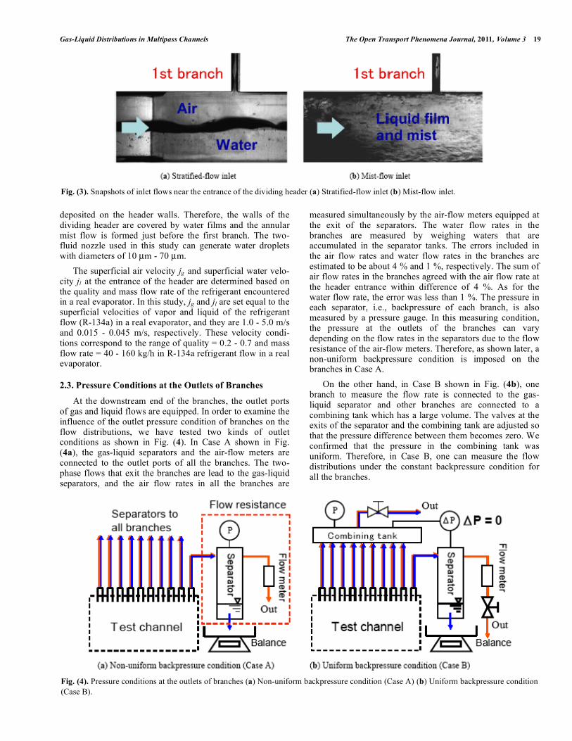
It is thought that the gas-liquid distributions to the branches are greatly influenced by the flow pattern in the dividing header. Hence, in this study, two contrastive flow-inlet conditions of the header entrance are adopted. One is the stratified-flow inlet. In this case, an air filter with a porous structure is stuffed in the developing region attached upstream the dividing header, and air and water is supplied separately at the upstream end of this developing region. The developing region has the same cross section as the header and a length of 300 mm. The stratified flow is formed at the entrance of the header. Fig. (3a) shows a snapshot of the flow near the entrance of the dividing header. It is observed that air and water is flowing separately and the stratified-flow inlet condition is realized at the header entrance. Under most conditions of the air and water superficial velocities tested in this study, the wavy-stratified flow was observed at the header entrance and the void fraction estimated from the visualized images was about 0.5 - 0.6. The other flow-inlet condition is the mist-flow inlet. A two-fluid nozzle is attached at the entrance of the header to generate a mist flow. The snapshot of the flow near the header entrance is shown in Fig. (3b). Air and water enters the header forming a mist flow, but water droplets are soon
Fig. (1). Schematic diagram of the experimental apparatus.
Gas-Liquid Distributions in Multipass Channels The Open Transport Phenomena Journal, 2011, Volume 3 19
deposited on the header walls. Therefore, the walls of the dividing header are covered by water films and the annular mist flow is formed just before the first branch. The two-fluid nozzle used in this study can generate water droplets with diameters of 10 µm - 70 µm. The superficial air velocity jg and superficial water velo-city jl at the entrance of the header are determined based on the quality and mass flow rate of the refrigerant encountered in a real evaporator. In this study, jg and jl are set equal to the superficial velocities of vapor and liquid of the refrigerant flow (R-134a) in a real evaporator, and they are 1.0 - 5.0 m/s and 0.015 - 0.045 m/s, respectively. These velocity condi-tions correspond to the range of quality = 0.2 - 0.7 and mass flow rate = 40 - 160 kg/h in R-134a refrigerant flow in a real evaporator.
2.3. Pressure Conditions at the Outlets of Branches
At the downstream end of the branches, the outlet ports of gas and liquid flows are equipped. In order to examine the influence of the outlet pressure condition of branches on the flow distributions, we have tested two kinds of outlet conditions as shown in Fig. (4). In Case A shown in Fig. (4a), the gas-liquid separators and the air-flow meters are connected to the outlet ports of all the branches. The two-phase flows that exit the branches are lead to the gas-liquid separators, and the air flow rates in all the branches are
measured simultaneously by the air-flow meters equipped at the exit of the separators. The water flow rates in the branches are measured by weighing waters that are accumulated in the separator tanks. The errors included in the air flow rates and water flow rates in the branches are estimated to be about 4 % and 1 %, respectively. The sum of air flow rates in the branches agreed with the air flow rate at the header entrance within difference of 4 %. As for the water flow rate, the error was less than 1 %. The pressure in each separator, i.e., backpressure of each branch, is also measured by a pressure gauge. In this measuring condition, the pressure at the outlets of the branches can vary depending on the flow rates in the separators due to the flow resistance of the air-flow meters. Therefore, as shown later, a non-uniform backpressure condition is imposed on the branches in Case A. On the other hand, in Case B shown in Fig. (4b), one branch to measure the flow rate is connected to the gas-liquid separator and other branches are connected to a combining tank which has a large volume. The valves at the exits of the separator and the combining tank are adjusted so that the pressure difference between them becomes zero. We confirmed that the pressure in the combining tank was uniform. Therefore, in Case B, one can measure the flow distributions under the constant backpressure condition for all the branches.
Fig. (3). Snapshots of inlet flows near the entrance of the dividing header (a) Stratified-flow inlet (b) Mist-flow inlet.
Fig. (4). Pressure conditions at the outlets of branches (a) Non-uniform backpressure condition (Case A) (b) Uniform backpressure condition (Case B).

20 The Open Transport Phenomena Journal, 2011, Volume 3 Razlan et al.
In many studies conducted to date, the flow distributions to the branches have been measured with the method equivalent to Case A. Therefore, those data are regarded as the results obtained under the non-uniform backpressure condition at the branch outlets.
2.4. Measurements of Pressure Distributions in the Headers
In a real compact evaporator, the downstream ends of the branches are connected to a combining header. In this study, we have measured the pressure distributions in the dividing and combining headers to make clear the pressure conditions at the branch outlets in a real evaporator. Fig. (5) shows an experimental apparatus for the measurements of the pressure distributions inside the headers. The dimensions of the test channel are essentially the same as those shown in Fig. (2), except that a horizontal combining header with a square cross section of 20 mm×20 mm is attached to the outlets of the branches. As shown in Fig. (5), the pressure distributions are measured at nine locations of each header. The pressure transducers are allocated at the middle of the side walls of the headers above and beneath the branches except for the first branch. They were calibrated with errors of less than 0.15 kPa. The sampling frequency of the pressure is 10 Hz and the measuring time is 60 seconds. In the combining header there are outlets at its right and left hand ends, and we have tested two flow conditions. One is the parallel flow, in which the gas and liquid enter the dividing header, go up through the branches to the combining header and exit from its right outlet. The other is the reverse flow, in which the flow exits from the left outlet of the combining header. The flow-inlet conditions at the entrance of the dividing header are the same as those for the flow-distribution measure-ments. The experimental conditions of this study are sum-marized in Table 1.
Table 1. Summary of the Experimental Conditions
Fluids Isothermal air and water
Superficial air velocity at the header entrance jg
1.0 m/s, 3.0 m/s, 5.0 m/s
Superficial water velocity at the header entrance jl
0.015 m/s, 0.03 m/s, 0.045 m/s
Pressure condition at the branch outlets
Non-uniform backpressure (Case A) Uniform backpressure (Case B)
Flow-inlet condition at the header entrance
Stratified-flow inlet Mist-flow inlet
Header attitude Horizontal
Branch attitude Vertical upward
Branch profile Flat tubes
Multi-port tubes
3. RESULTS AND DISCUSSION
3.1. Flow Distributions under the Stratified-Flow Inlet
In this section, the air and water flow distribution charac-teristics measured under the stratified-flow inlet condition (Fig. 3a) are addressed. Fig. (6) shows an example of snap-shots of the flow in the dividing header under the stratified-flow inlet condition. It was found that water was distributed to the branches unsteadily by large waves but the down-stream region of the dividing header was blocked by stagnant water. At first, the influence of the backpressure condition at the branch outlets on the flow distributions is examined in detail. As a baseline, the results of air and water distributions obtained in the channel with flat tube branches are shown in
Fig. (5). Test channel for the pressure distribution measurements in the headers.

Gas-Liquid Distributions in Multipass Channels The Open Transport Phenomena Journal, 2011, Volume 3 21
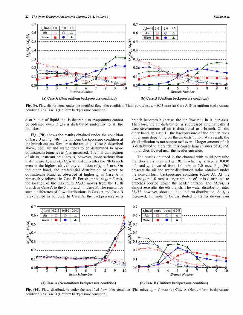
Fig. (7). The abscissa shows the branch number and the branch located nearest the header entrance is denoted as "1". The ordinate shows the air distribution ratio Mgi/Mg (broken lines) and the water distribution ratio Mli/Ml (solid lines) measured in the i th branch (i = 1 ~ 10). The superficial water velocity at the header entrance jl is fixed at 0.030 m/s, and the superficial air velocity jg is varied as 1.0 m/s, 3.0 m/s and 5.0 m/s. The pressure distributions at the branch outlets measured in Case A are shown in Fig. (8). The backpressure is highest in the first branch, and it decreases gradually in the branches located further downstream. From this result one can confirm that the non-uniform backpressure condition is imposed on the branches in Case A. Fig. (7a) shows the results obtained under the non-uniform backpressure condition (Case A in Fig. (4a)). At the lowest air velocity of jg = 1.0 m/s, larger amount of air is distributed to branches located nearer the header entrance and Mgi/Mg is almost zero after the 6th branch. The water distribution ratio Mli/Ml also shows relatively large values in upstream branches but it attains the maximum in the 4th branch. This branch corresponds to the location at which the crests of the large waves generated in the header reach the top wall of the dividing header. As observed in Fig. (6), water is distributed to the branches unsteadily by large waves generated in the dividing header and it was found that the location where they occurred moved downstream as jg was increased. At low jg, the downstream region of the header is blocked by stagnant water as observed in Fig. (6) and very little amount of air and water is distributed to the branches there.
As jg is increased, air tends to be distributed to more downstream branches and air is distributed almost uniformly to all the branches at jg = 5 m/s. A close correlation is observed between the air distribution ratios and the pressure distribution at the outlets of the branches shown in Fig. (8). This is because the pressure loss in the gas-flow meter settled at the exit of the separator increases in proportion to the air flow rate. On the other hand, the water tends to be distributed preferentially to the downstream branches as jg is increased, and the mal-distribution of water is further enhanced at higher jg. These results mean that a uniform
Fig. (8). Pressure distributions at the branch outlets in Case A (Flat tubes, jl = 0.03 m/s).
Fig. (6). Snapshot of the flow in the dividing header under the stratified-flow inlet condition.
Fig. (7). Flow distributions under the stratified-flow inlet condition (Flat tubes, jl = 0.03 m/s) (a) Case A (Non-uniform backpressure condition) (b) Case B (Uniform backpressure condition).
0.0
0.4
0.8
1.2
1.6
1 2 3 4 5 6 7 8 9 10Branch Number
2.0
P[k
Pa] □
○
△
jg m/s1.03.05.0
22 The Open Transport Phenomena Journal, 2011, Volume 3 Razlan et al.
distribution of liquid that is desirable to evaporators cannot be obtained even if gas is distributed uniformly to all the branches. Fig. (7b) shows the results obtained under the condition of Case B in Fig. (4b), the uniform backpressure condition at the branch outlets. Similar to the results of Case A described above, both air and water tends to be distributed to more downstream branches as jg is increased. The mal-distribution of air to upstream branches is, however, more serious than that in Case A, and Mgi/Mg is almost zero after the 7th branch even in the highest air velocity condition of jg = 5 m/s. On the other hand, the preferential distribution of water to downstream branches observed at higher jg in Case A is remarkably relieved in Case B. For example, at jg = 5 m/s, the location of the maximum Mli/Ml moves from the 10 th branch in Case A to the 5 th branch in Case B. The reason for such a difference of flow distributions in Case A and Case B is explained as follows. In Case A, the backpressure of a
branch becomes higher as the air flow rate in it increases. Therefore, the air distribution is suppressed automatically if excessive amount of air is distributed to a branch. On the other hand, in Case B, the backpressure of the branch does not change depending on the air distribution. As a result, the air distribution is not suppressed even if larger amount of air is distributed to a branch; this causes larger values of Mgi/Mg in branches located near the header entrance. The results obtained in the channel with multi-port tube branches are shown in Fig. (9), in which jl is fixed at 0.030 m/s and jg is varied from 1.0 m/s to 5.0 m/s. Fig. (9a) presents the air and water distribution ratios obtained under the non-uniform backpressure condition (Case A). At the lowest jg = 1.0 m/s, a larger amount of air is distributed to branches located nearer the header entrance and Mgi/Mg is almost zero after the 6th branch. The water distribution ratio Mli/Ml, however, shows quite a uniform distribution. As jg is increased, air tends to be distributed to further downstream
Fig. (9). Flow distributions under the stratified-flow inlet condition (Multi-port tubes, jl = 0.03 m/s) (a) Case A (Non-uniform backpressure condition) (b) Case B (Uniform backpressure condition).
Fig. (10). Flow distributions under the stratified-flow inlet condition (Flat tubes, jg = 5 m/s) (a) Case A (Non-uniform backpressure condition) (b) Case B (Uniform backpressure condition).

Gas-Liquid Distributions in Multipass Channels The Open Transport Phenomena Journal, 2011, Volume 3 23
branches and at jg = 5 m/s air is distributed almost uniformly to the branches except last two branches. On the other hand, water tends to be distributed preferentially to downstream branches as jg is increased, thus the mal-distribution of water is enhanced at higher jg. These results of air and water distributions in the multi-port tube channel for Case A are qualitatively similar to those observed in the flat tube channel for Case A shown in Fig. (7a). The mal-distribution of water to downstream branches at high jg is, however, relieved with the multi-port tubes. Fig. (9b) shows the results for the uniform outlet pressure condition (Case B). The flow distribution characteristics observed under this backpressure condition agree well with those of Case A described above. This means that, in case of the multi-port tubes, the backpressure conditions at the branch outlets exert only minor influences on the flow distributions. Because the pressure losses of the multi-port tubes are much larger than those of the flat tubes, the influence of the pressure variations at the branch outlets on the flow distributions becomes relatively small. Next, the influences of the superficial water velocity jl on the flow distributions are discussed. Figs. (10a) and (10b) show the results obtained with the flat tubes under the backpressure conditions of Case A and Case B, respectively. The superficial air velocity jg is fixed at 5.0 m/s, and jl is changed from 0.015 m/s to 0.045 m/s. In Case A, the air and water distribution ratios do not change depending on jl, and it follows that the flow distribution characteristics are
determined solely by jg. In Case B, both Mgi/Mg and Mli/Ml in the upstream branches become larger as jl is increased. From a comparison of Fig. (7b) and Fig. (10b), however, it is found that jg exerts greater influences on the gas and liquid distributions than jl in Case B as well as in Case A. The results obtained in the multi-port tube channel are shown in Fig. (11). The influences of the backpressure conditions and of jl are not observed at all in Mgi/Mg and Mli/Ml, and the flow distribution characteristics are qualita-tively similar to those observed in Case A with the flat tube channel.
3.2. Flow Distributions under the Mist-Flow Inlet
The results shown so far were obtained under the stratified-flow inlet condition. As a contrastive case, we measured the flow distributions under the mist-flow inlet condition and the results are discussed in this section. A snapshot of the flow in the dividing header is shown in Fig. (12). It is observed that the annular mist flow is formed near the header entrance, but air and water tends to be separated in a downstream region of the header. The large waves such as observed in the stratified-flow inlet are not generated in this flow-inlet condition. At low jg, water stagnates in the downstream region of the dividing header as is the case with the stratified-flow inlet. At first, the results obtained in the channel with flat tubes are addressed. Figs. (13a) and (13b) show the air and water distributions measured under the non-uniform backpressure
Fig. (11). Flow distributions under the stratified-flow inlet condition (Multi-port tubes, jg = 5 m/s) (a) Case A (Non-uniform backpressure condition) (b) Case B (Uniform backpressure condition).
Fig. (12). Snapshot of the flow in the dividing header under the mist-flow inlet condition.

24 The Open Transport Phenomena Journal, 2011, Volume 3 Razlan et al.
condition (Case A) and the uniform backpressure condition (Case B), respectively, at constant jl = 0.03 m/s. The superficial air velocities at the header entrance jg are the same as those of Fig. (7). In Case A, the air distribution ratios Mgi/Mg show qualitatively similar characteristics to those in the stratified-flow inlet shown in Fig. (7a), but the uniformity of the water distribution is improved especially at high jg. At the lowest jg of 1 m/s, however, Mli/Ml is very low in the 4th - 7th branches. This is explained as follows. In this middle region of the dividing header, water flows in the lower part of the header cross section at low jg and is not distributed to the branches because the water film initially formed over the top wall of the header is distributed into the upstream branches. At larger air velocity, water droplets are distributed to the branches located in the middle region and relatively uniform distribution of water is achieved.
In Case B shown in Fig. (13b), similar to the results obtained in the stratified-flow inlet under the uniform backpressure condition, most of air is distributed to the first and second branches at low jg of 1.0 m/s. As jg is increased, Mgi/Mg in these branches decreases and air tends to be distributed to the branches in the downstream region as well. As a result, the uniformity of the air distribution is improved in comparison with that for the stratified-flow inlet. The mal-distribution of air to the upstream branches is, however, enhanced in comparison with Case A of the mist-flow inlet. The water distribution shows qualitatively similar charac-teristics to that of Case A. From a comparison of Fig. (7) and Fig. (13), it follows that under the mist-flow inlet condition with flat tubes the pressure condition at the branch outlets exerts minor influence on the water distributions in com-parison with the stratified-flow inlet. In the mist-flow inlet, water droplets and liquid film formed over the header walls have a direct influence on the water distributions to the
Fig. (13). Flow distributions under the mist-flow inlet condition (Flat tubes, jl = 0.03 m/s) (a) Case A (Non-uniform backpressure condition) (b) Case B (Uniform backpressure condition).
Fig. (14). Flow distributions under the mist-flow inlet condition (Multi-port tubes, jl = 0.03 m/s) (a) Case A (Non-uniform backpressure condition) (b) Case B (Uniform backpressure condition).
Gas-Liquid Distributions in Multipass Channels The Open Transport Phenomena Journal, 2011, Volume 3 25
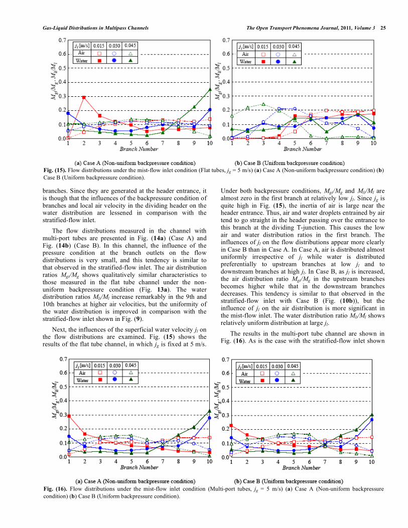
branches. Since they are generated at the header entrance, it is though that the influences of the backpressure condition of branches and local air velocity in the dividing header on the water distribution are lessened in comparison with the stratified-flow inlet. The flow distributions measured in the channel with multi-port tubes are presented in Fig. (14a) (Case A) and Fig. (14b) (Case B). In this channel, the influence of the pressure condition at the branch outlets on the flow distributions is very small, and this tendency is similar to that observed in the stratified-flow inlet. The air distribution ratios Mgi/Mg shows qualitatively similar characteristics to those measured in the flat tube channel under the non-uniform backpressure condition (Fig. 13a). The water distribution ratios Mli/Ml increase remarkably in the 9th and 10th branches at higher air velocities, but the uniformity of the water distribution is improved in comparison with the stratified-flow inlet shown in Fig. (9). Next, the influences of the superficial water velocity jl on the flow distributions are examined. Fig. (15) shows the results of the flat tube channel, in which jg is fixed at 5 m/s.
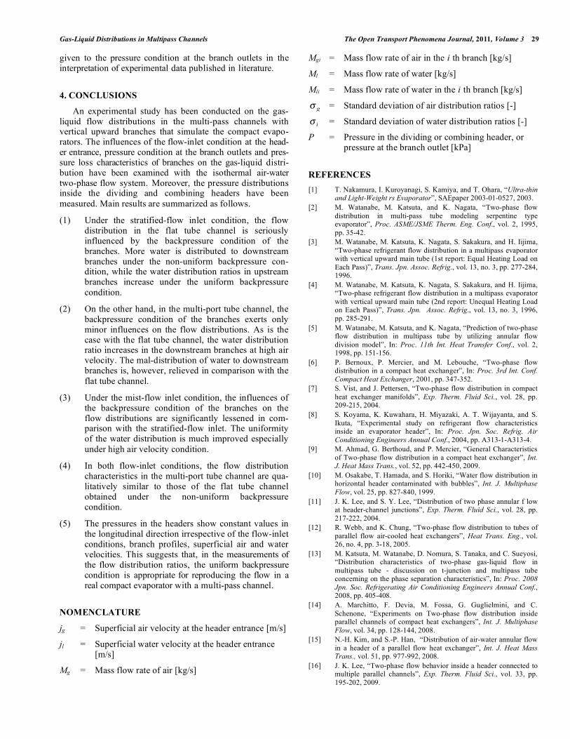
Under both backpressure conditions, Mgi/Mg and Mli/Ml are almost zero in the first branch at relatively low jl. Since jg is quite high in Fig. (15), the inertia of air is large near the header entrance. Thus, air and water droplets entrained by air tend to go straight in the header passing over the entrance to this branch at the dividing T-junction. This causes the low air and water distribution ratios in the first branch. The influences of jl on the flow distributions appear more clearly in Case B than in Case A. In Case A, air is distributed almost uniformly irrespective of jl while water is distributed preferentially to upstream branches at low jl and to downstream branches at high jl. In Case B, as jl is increased, the air distribution ratio Mgi/Mg in the upstream branches becomes higher while that in the downstream branches decreases. This tendency is similar to that observed in the stratified-flow inlet with Case B (Fig. (10b)), but the influence of jl on the air distribution is more significant in the mist-flow inlet. The water distribution ratio Mli/Ml shows relatively uniform distribution at large jl. The results in the multi-port tube channel are shown in Fig. (16). As is the case with the stratified-flow inlet shown
Fig. (15). Flow distributions under the mist-flow inlet condition (Flat tubes, jg = 5 m/s) (a) Case A (Non-uniform backpressure condition) (b) Case B (Uniform backpressure condition).
Fig. (16). Flow distributions under the mist-flow inlet condition (Multi-port tubes, jg = 5 m/s) (a) Case A (Non-uniform backpressure condition) (b) Case B (Uniform backpressure condition).

26 The Open Transport Phenomena Journal, 2011, Volume 3 Razlan et al.
in Fig. (11), the pressure condition at the branch outlets exerts only minor influences on the flow distribution. The dependences of Mgi/Mg and Mli/Ml on jl are similar to those observed in the flat tube channel under the non-uniform backpressure condition (Fig. 15a).
3.3. Evaluation of Uniformity of Flow Distributions
As described so far, the air-water distribution charac-teristics in the multi-pass channels change in a complex manner depending on the flow inlet condition at the header entrance, pressure condition at the branch outlet, and the branch profile. In the application of these channels to compact heat exchangers, a uniform flow distribution to all the branches is ideal for high thermal performance. In this study, in order to evaluate the uniformity of the air and water distributions to the branches, the standard deviations of Mgi/Mg and Mli/Ml, denoted as g! and
l! respectively, have
been calculated by the following equations. The smaller values of g! and
l! statistically correspond to the higher
uniformity of the air and water distributions [14].
NNM
MN
i g
gi
g /1
1
2
!=
""#
$%%&
'(=) (N = 10) (1)
NNM
MN
i l
li
l/
1
1
2
!=
""#
$%%&
'(=) (N = 10) (2)
Figs. (17) and (18) show the results of g! and l
! , respectively, obtained with the stratified-flow inlet. Figs. (a) and (b) correspond to the backpressure conditions of Case A and Case B, respectively. The abscissa shows the superficial air velocity jg, and the results in the flat tube channel and the multi-port tube channel are compared in each figure. In both branch profiles and backpressure conditions, g! decreases as jg is increased. The influence of the branch profile on g! appears clearly in Case B (uniform backpressure condition).
Fig. (17). Standard deviations of the air distribution ratios g! under the stratified-flow inlet condition (a) Case A (Non-uniform backpressure condition) (b) Case B (Uniform backpressure condition).
Fig. (18). Standard deviations of the water distribution ratios l
! under the stratified-flow inlet condition (a) Case A (Non-uniform backpressure condition) (b) Case B (Uniform backpressure condition).

Gas-Liquid Distributions in Multipass Channels The Open Transport Phenomena Journal, 2011, Volume 3 27
On the other hand, l
! increases almost linearly with jg. As a whole, the standard deviation of the water distribution ratios shows smaller values in the multi-port tube channel. This means that the uniformity of the liquid distributions to the branches is improved with the multi-port tubes in the stratified-flow inlet condition. Next, the results of g! and
l! for the mist-flow inlet are
shown in Fig. (19) and Fig. (20). The distributions of g! are qualitatively similar to those obtained with the stratified-flow inlet, but the difference between the flat tubes and the multi-port tubes in Case B is somewhat smaller than that found in Fig. (17b). In
l! , no distinct difference is observed
between these tube profiles. As a general trend, l
! for the mist-flow inlet shows smaller values than that for the stra-tified-flow inlet irrespective of the backpressure condition and the branch profile. This suggests that the flow pattern in the dividing header is the decisive factor for the uniformity of the liquid distribution to the branches.
3.4. Pressure Distributions Inside Headers
As described above, we tested two kinds of pressure conditions at the branch outlets and found that the back-pressure conditions exerted a great influence on the flow distribution to the branches especially in the stratified-flow inlet. In a real compact evaporator, the downstream ends of the branches are connected to a combining header, and it is not clear which backpressure condition is appropriate to reproduce a flow condition in it. Hence, in this study, we measured the pressure distributions in the dividing and combining headers to make clear the pressure conditions at the branch outlets in a real evaporator and to find out an appropriate backpressure condition in the measurement of the flow distributions. Since the flow-inlet condition and the direction of the flow in the combining header (parallel flow or reverse flow in Fig. (5)) did not exert significant influences on the pressure distributions in the headers, the
Fig. (19). Standard deviations of the air distribution ratios g! under the mist-flow inlet condition (a) Case A (Non-uniform backpressure condition) (b) Case B (Uniform backpressure condition).
Fig. (20). Standard deviations of the water distribution ratios
l! under the mist-flow inlet condition (a) Case A (Non-uniform backpressure
condition) (b) Case B (Uniform backpressure condition).

28 The Open Transport Phenomena Journal, 2011, Volume 3 Razlan et al.
results measured under the stratified-flow inlet with the parallel flow condition are shown here. Figs. (21) and (22) present the typical pressure distribu-tions along the dividing and combining headers measured in the flat tube channel and the multi-port tube channel, respectively. The abscissa shows the positions of the pres-sure sensors along each header, starting from the second branch. The pressure distributions in the dividing and combining headers are shown by the solid and broken lines, respectively. jl is set at 0.030 m/s with the variation of jg from 1.0 m/s to 5.0 m/s. In these figures, the pressures in
both headers show almost constant values in the longitu-dinal direction irrespective of the values of jg and branch profiles. This suggests that, in real evaporators, the outlets of all the branches are kept at the same pressure. Therefore, in the measurements of the flow distribution characteristics, the gas-liquid distribution ratios close to a real evaporator are expected to appear by imposing the uniform backpressure condition, Case B in Fig. (4b), on the branches. As des-cribed in this paper, the backpressure condition of the branches exerts direct influences on the flow distributions in the flat tube channel. Thus, considerable care should be
Fig. (21). Pressure distributions in the dividing and combining headers under the stratified-flow inlet (Flat tubes, jl = 0.03 m/s).
Fig. (22). Pressure distributions in the dividing and combining headers under the stratified-flow inlet (Multi-port tubes, jl = 0.03 m/s).
2 3 4 5 6 7 8 9 10Sensor Position [Branch Number]
0.0
4.0
6.0
8.0
2.0
10.0
P[k
Pa]
(1) jg = 1.0 m/s Dividing header Combining header(2) jg = 3.0 m/s Dividing header Combining header(3) jg = 5.0 m/s Dividing header Combining header
■
●
▲
□
○
△
jl = 0.030 m/s
2 3 4 5 6 7 8 9 10Sensor Position [Branch Number]
0.0
4.0
6.0
8.0
2.0
10.0
P[k
Pa]
(1) jg = 1.0 m/s Dividing header Combining header(2) jg = 3.0 m/s Dividing header Combining header(3) jg = 5.0 m/s Dividing header Combining header
■
●
▲
□
○
△
jl = 0.030 m/s
Gas-Liquid Distributions in Multipass Channels The Open Transport Phenomena Journal, 2011, Volume 3 29
given to the pressure condition at the branch outlets in the interpretation of experimental data published in literature.
4. CONCLUSIONS
An experimental study has been conducted on the gas-liquid flow distributions in the multi-pass channels with vertical upward branches that simulate the compact evapo-rators. The influences of the flow-inlet condition at the head-er entrance, pressure condition at the branch outlets and pres-sure loss characteristics of branches on the gas-liquid distri-bution have been examined with the isothermal air-water two-phase flow system. Moreover, the pressure distributions inside the dividing and combining headers have been measured. Main results are summarized as follows.
(1) Under the stratified-flow inlet condition, the flow distribution in the flat tube channel is seriously influenced by the backpressure condition of the branches. More water is distributed to downstream branches under the non-uniform backpressure con-dition, while the water distribution ratios in upstream branches increase under the uniform backpressure condition.
(2) On the other hand, in the multi-port tube channel, the backpressure condition of the branches exerts only minor influences on the flow distributions. As is the case with the flat tube channel, the water distribution ratio increases in the downstream branches at high air velocity. The mal-distribution of water to downstream branches is, however, relieved in comparison with the flat tube channel.
(3) Under the mist-flow inlet condition, the influences of the backpressure condition of the branches on the flow distributions are significantly lessened in com-parison with the stratified-flow inlet. The uniformity of the water distribution is much improved especially under high air velocity condition.
(4) In both flow-inlet conditions, the flow distribution characteristics in the multi-port tube channel are qua-litatively similar to those of the flat tube channel obtained under the non-uniform backpressure condition.
(5) The pressures in the headers show constant values in the longitudinal direction irrespective of the flow-inlet conditions, branch profiles, superficial air and water velocities. This suggests that, in the measurements of the flow distribution ratios, the uniform backpressure condition is appropriate for reproducing the flow in a real compact evaporator with a multi-pass channel.
NOMENCLATURE
jg = Superficial air velocity at the header entrance [m/s]
jl = Superficial water velocity at the header entrance [m/s]
Mg = Mass flow rate of air [kg/s]
Mgi = Mass flow rate of air in the i th branch [kg/s]
Ml = Mass flow rate of water [kg/s]
Mli = Mass flow rate of water in the i th branch [kg/s]
g! = Standard deviation of air distribution ratios [-]
l! = Standard deviation of water distribution ratios [-]
P = Pressure in the dividing or combining header, or pressure at the branch outlet [kPa]
REFERENCES [1] T. Nakamura, I. Kuroyanagi, S. Kamiya, and T. Ohara, “Ultra-thin
and Light-Weight rs Evaporator”, SAEpaper 2003-01-0527, 2003. [2] M. Watanabe, M. Katsuta, and K. Nagata, “Two-phase flow
distribution in multi-pass tube modeling serpentine type evaporator”, Proc. ASME/JSME Therm. Eng. Conf., vol. 2, 1995, pp. 35-42.
[3] M. Watanabe, M. Katsuta, K. Nagata, S. Sakakura, and H. Iijima, “Two-phase refrigerant flow distribution in a multipass evaporator with vertical upward main tube (1st report: Equal Heating Load on Each Pass)”, Trans. Jpn. Assoc. Refrig., vol. 13, no. 3, pp. 277-284, 1996.
[4] M. Watanabe, M. Katsuta, K. Nagata, S. Sakakura, and H. Iijima, “Two-phase refrigerant flow distribution in a multipass evaporator with vertical upward main tube (2nd report: Unequal Heating Load on Each Pass)”, Trans. Jpn. Assoc. Refrig., vol. 13, no. 3, 1996, pp. 285-291.
[5] M. Watanabe, M. Katsuta, and K. Nagata, “Prediction of two-phase flow distribution in multipass tube by utilizing annular flow division model”, In: Proc. 11th Int. Heat Transfer Conf., vol. 2, 1998, pp. 151-156.
[6] P. Bernoux, P. Mercier, and M. Lebouche, “Two-phase flow distribution in a compact heat exchanger”, In: Proc. 3rd Int. Conf. Compact Heat Exchanger, 2001, pp. 347-352.
[7] S. Vist, and J. Pettersen, “Two-phase flow distribution in compact heat exchanger manifolds”, Exp. Therm. Fluid Sci., vol. 28, pp. 209-215, 2004.
[8] S. Koyama, K. Kuwahara, H. Miyazaki, A. T. Wijayanta, and S. Ikuta, “Experimental study on refrigerant flow characteristics inside an evaporator header”, In: Proc. Jpn. Soc. Refrig. Air Conditioning Engineers Annual Conf., 2004, pp. A313-1-A313-4.
[9] M. Ahmad, G. Berthoud, and P. Mercier, “General Characteristics of Two-phase flow distribution in a compact heat exchanger”, Int. J. Heat Mass Trans., vol. 52, pp. 442-450, 2009.
[10] M. Osakabe, T. Hamada, and S. Horiki, “Water flow distribution in horizontal header contaminated with bubbles”, Int. J. Multiphase Flow, vol. 25, pp. 827-840, 1999.
[11] J. K. Lee, and S. Y. Lee, “Distribution of two phase annular f low at header-channel junctions”, Exp. Therm. Fluid Sci., vol. 28, pp. 217-222, 2004.
[12] R. Webb, and K. Chung, “Two-phase flow distribution to tubes of parallel flow air-cooled heat exchangers”, Heat Trans. Eng., vol. 26, no. 4, pp. 3-18, 2005.
[13] M. Katsuta, M. Watanabe, D. Nomura, S. Tanaka, and C. Sueyosi, “Distribution characteristics of two-phase gas-liquid flow in multipass tube - discussion on t-junction and multipass tube concerning on the phase separation characteristics”, In: Proc. 2008 Jpn. Soc. Refrigerating Air Conditioning Engineers Annual Conf., 2008, pp. 405-408.
[14] A. Marchitto, F. Devia, M. Fossa, G. Guglielmini, and C. Schenone, “Experiments on Two-phase flow distribution inside parallel channels of compact heat exchangers”, Int. J. Multiphase Flow, vol. 34, pp. 128-144, 2008.
[15] N.-H. Kim, and S.-P. Han, “Distribution of air-water annular flow in a header of a parallel flow heat exchanger”, Int. J. Heat Mass Trans., vol. 51, pp. 977-992, 2008.
[16] J. K. Lee, “Two-phase flow behavior inside a header connected to multiple parallel channels”, Exp. Therm. Fluid Sci., vol. 33, pp. 195-202, 2009.

30 The Open Transport Phenomena Journal, 2011, Volume 3 Razlan et al.
[17] M. Katsuta, K. Yamagata, and K. Fukai, In: Proc. Jpn. Soc. Refrigerating Air Conditioning Engineers Annual Conf., 2009, pp. 551-554.
[18] S. Y. Lee, “Flow distribution behavior in condensers and evaporators”, In: Proc. 13th Int. Heat Transfer Conf., KN-08, in CD-ROM, 2006.
Received: February 08, 2011 Revised: March 24, 2011 Accepted: March 26, 2011 © Razlan et al.; Licensee Bentham Open.
This is an open access article licensed under the terms of the Creative Commons Attribution Non-Commercial License (http://creativecommons.org/ licenses/by-nc/3.0/), which permits unrestricted, non-commercial use, distribution and reproduction in any medium, provided the work is properly cited.