Embed Size (px)
Citation preview
Open CloudServer OCS Solid State Drive
Version 2.0
Author:
Laura Caulfield, Software Engineer II, Microsoft
Open Compute Project Open CloudServer OCS Solid State Drive
http://opencompute.org ii
Revision History
Date Description
2/25/2015 Version 2.0
Open Compute Project Open CloudServer Solid State Drive
http://opencompute.org iii
© 2015 Microsoft Corporation.
As of October 30, 2014, the following persons or entities have made this Specification available under the Open Web
Foundation Final Specification Agreement (OWFa 1.0), which is available at http://www.openwebfoundation.org/legal/the-owf-
1-0-agreements/owfa-1-0
Microsoft Corporation.
You can review the signed copies of the Open Web Foundation Agreement Version 1.0 for this Specification at
http://opencompute.org/licensing/, which may also include additional parties to those listed above.
Your use of this Specification may be subject to other third party rights. THIS SPECIFICATION IS PROVIDED "AS IS." The
contributors expressly disclaim any warranties (express, implied, or otherwise), including implied warranties of merchantability,
noninfringement, fitness for a particular purpose, or title, related to the Specification. The entire risk as to implementing or
otherwise using the Specification is assumed by the Specification implementer and user. IN NO EVENT WILL ANY PARTY BE
LIABLE TO ANY OTHER PARTY FOR LOST PROFITS OR ANY FORM OF INDIRECT, SPECIAL, INCIDENTAL, OR CONSEQUENTIAL
DAMAGES OF ANY CHARACTER FROM ANY CAUSES OF ACTION OF ANY KIND WITH RESPECT TO THIS SPECIFICATION OR ITS
GOVERNING AGREEMENT, WHETHER BASED ON BREACH OF CONTRACT, TORT (INCLUDING NEGLIGENCE), OR OTHERWISE, AND
WHETHER OR NOT THE OTHER PARTY HAS BEEN ADVISED OF THE POSSIBILITY OF SUCH DAMAGE.
CONTRIBUTORS AND LICENSORS OF THIS SPECIFICATION MAY HAVE MENTIONED CERTAIN TECHNOLOGIES THAT ARE MERELY
REFERENCED WITHIN THIS SPECIFICATION AND NOT LICENSED UNDER THE OWF CLA OR OWFa. THE FOLLOWING IS A LIST OF
MERELY REFERENCED TECHNOLOGY: INTELLIGENT PLATFORM MANAGEMENT INTERFACE (IPMI), I2C TRADEMARK OF PHILLIPS
SEMICONDUCTOR. IMPLEMENTATION OF THESE TECHNOLOGIES MAY BE SUBJECT TO THEIR OWN LEGAL TERMS.
iv February 25, 2015
Contents 1 Summary ....................................................................................................................................................... 1
2 Reference Documents ................................................................................................................................... 1
2.1 Applicable Documents .................................................................................................................................. 1
2.2 Order of Preference ...................................................................................................................................... 2
3 Operating System and Boot Requirements .................................................................................................... 2
4 Performance .................................................................................................................................................. 2
4.1 Bandwidth & Throughput ............................................................................................................................. 3
4.2 Latency ......................................................................................................................................................... 3
4.3 No I/O Throttling to Reduce Wear ............................................................................................................... 4
5 Power ............................................................................................................................................................ 4
5.1 NVMe Drives ................................................................................................................................................. 4
5.2 AHCI Drives ................................................................................................................................................... 4
6 Thermal & Mechanical .................................................................................................................................. 5
6.1 Thermal ........................................................................................................................................................ 5
6.2 Mechanical ................................................................................................................................................... 6
7 Endurance ..................................................................................................................................................... 7
8 S.M.A.R.T. Attributes ..................................................................................................................................... 7
8.1 NVMe ......................................................................................................................................................... 10
8.2 AHCI ............................................................................................................................................................ 10
9 Commands .................................................................................................................................................. 10
9.1 Firmware Update ....................................................................................................................................... 10
9.2 Disk Reconditioning Tool & Crypto-Erase ................................................................................................... 10
9.3 Debugging Logs .......................................................................................................................................... 11
10 Unplanned Power Loss ................................................................................................................................ 11
10.1 Drives with Volatile Write Cache ................................................................................................................ 11
10.2 Drives with Non-Volatile Write Cache ........................................................................................................ 11
10.2.1 System-Assisted NV Write Cache ...................................................................................................... 12
10.2.2 Fast Flushing ...................................................................................................................................... 12
11 Data Security ............................................................................................................................................... 12
Open Compute Project Open CloudServer Solid State Drive
http://opencompute.org v
Table of Figures Figure 1: Air Property Pictorial ...................................................................................................................... 5
Figure 2: Memory Card Environmental Requirement .................................................................................. 6
vi February 25, 2015
Table of Tables Table 1: Device Summary .............................................................................................................................. 1
Table 2: Reference Documents ..................................................................................................................... 2
Table 3: Throughput Targets ......................................................................................................................... 3
Table 4: Latency Targets ............................................................................................................................... 3
Table 5: Additional SMART Attributes .......................................................................................................... 9
http://opencompute.org 1
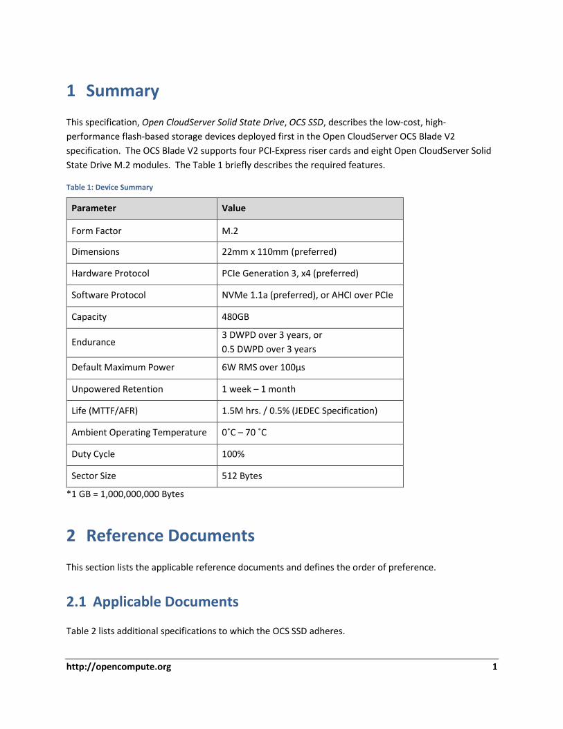
1 Summary
This specification, Open CloudServer Solid State Drive, OCS SSD, describes the low-cost, high-
performance flash-based storage devices deployed first in the Open CloudServer OCS Blade V2
specification. The OCS Blade V2 supports four PCI-Express riser cards and eight Open CloudServer Solid
State Drive M.2 modules. The Table 1 briefly describes the required features.
Table 1: Device Summary
Parameter Value
Form Factor M.2
Dimensions 22mm x 110mm (preferred)
Hardware Protocol PCIe Generation 3, x4 (preferred)
Software Protocol NVMe 1.1a (preferred), or AHCI over PCIe
Capacity 480GB
Endurance 3 DWPD over 3 years, or
0.5 DWPD over 3 years
Default Maximum Power 6W RMS over 100µs
Unpowered Retention 1 week – 1 month
Life (MTTF/AFR) 1.5M hrs. / 0.5% (JEDEC Specification)
Ambient Operating Temperature 0˚C – 70 ˚C
Duty Cycle 100%
Sector Size 512 Bytes
*1 GB = 1,000,000,000 Bytes
2 Reference Documents
This section lists the applicable reference documents and defines the order of preference.
2.1 Applicable Documents
Table 2 lists additional specifications to which the OCS SSD adheres.
2 February 25, 2015
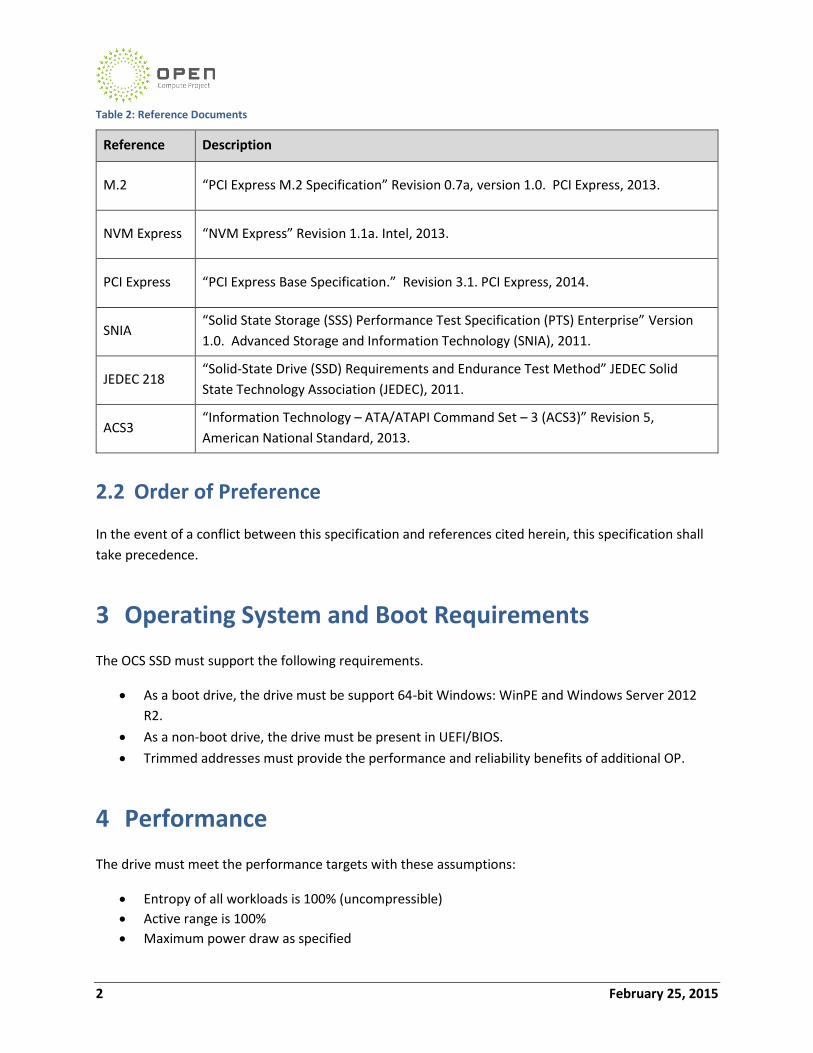
Table 2: Reference Documents
Reference Description
M.2 “PCI Express M.2 Specification” Revision 0.7a, version 1.0. PCI Express, 2013.
NVM Express “NVM Express” Revision 1.1a. Intel, 2013.
PCI Express “PCI Express Base Specification.” Revision 3.1. PCI Express, 2014.
SNIA “Solid State Storage (SSS) Performance Test Specification (PTS) Enterprise” Version
1.0. Advanced Storage and Information Technology (SNIA), 2011.
JEDEC 218 “Solid-State Drive (SSD) Requirements and Endurance Test Method” JEDEC Solid
State Technology Association (JEDEC), 2011.
ACS3 “Information Technology – ATA/ATAPI Command Set – 3 (ACS3)” Revision 5,
American National Standard, 2013.
2.2 Order of Preference
In the event of a conflict between this specification and references cited herein, this specification shall
take precedence.
3 Operating System and Boot Requirements
The OCS SSD must support the following requirements.
As a boot drive, the drive must be support 64-bit Windows: WinPE and Windows Server 2012
R2.
As a non-boot drive, the drive must be present in UEFI/BIOS.
Trimmed addresses must provide the performance and reliability benefits of additional OP.
4 Performance
The drive must meet the performance targets with these assumptions:
Entropy of all workloads is 100% (uncompressible)
Active range is 100%
Maximum power draw as specified
Open Compute Project Open CloudServer Solid State Drive
http://opencompute.org 3
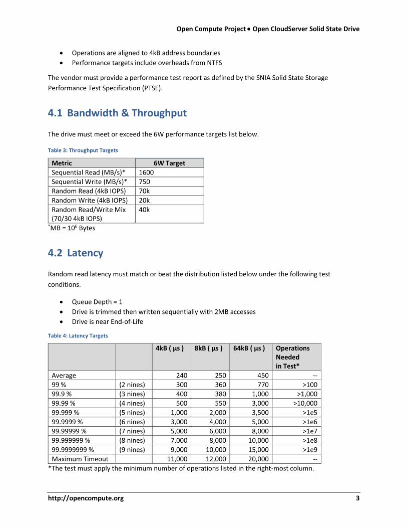
Operations are aligned to 4kB address boundaries
Performance targets include overheads from NTFS
The vendor must provide a performance test report as defined by the SNIA Solid State Storage
Performance Test Specification (PTSE).
4.1 Bandwidth & Throughput
The drive must meet or exceed the 6W performance targets list below.
Table 3: Throughput Targets
Metric 6W Target
Sequential Read (MB/s)* 1600
Sequential Write (MB/s)* 750
Random Read (4kB IOPS) 70k
Random Write (4kB IOPS) 20k
Random Read/Write Mix (70/30 4kB IOPS)
40k
*MB = 106 Bytes
4.2 Latency
Random read latency must match or beat the distribution listed below under the following test
conditions.
Queue Depth = 1
Drive is trimmed then written sequentially with 2MB accesses
Drive is near End-of-Life
Table 4: Latency Targets
4kB ( µs ) 8kB ( µs ) 64kB ( µs ) Operations
Needed in Test*
Average 240 250 450 --
99 % (2 nines) 300 360 770 >100
99.9 % (3 nines) 400 380 1,000 >1,000
99.99 % (4 nines) 500 550 3,000 >10,000
99.999 % (5 nines) 1,000 2,000 3,500 >1e5
99.9999 % (6 nines) 3,000 4,000 5,000 >1e6
99.99999 % (7 nines) 5,000 6,000 8,000 >1e7
99.999999 % (8 nines) 7,000 8,000 10,000 >1e8
99.9999999 % (9 nines) 9,000 10,000 15,000 >1e9
Maximum Timeout 11,000 12,000 20,000 --
*The test must apply the minimum number of operations listed in the right-most column.
4 February 25, 2015
4.3 No I/O Throttling to Reduce Wear
All SSD solutions are to provide performance consistent with the capabilities of the flash and controller.
The drive:
Must not throttle the performance for the purpose of distributing wear on the flash over time
Must continue to allow writes as long as possible after the media wear indicator reaches 100%
5 Power
The drive must support dynamic switching between power states in which the host can perform I/O.
The drive must report at least one power state for each level:
Required: Maximum of 6W,
Optional: Maximum of 8W and 10W
Some blade configurations may leverage the optional power states for higher performance, but there is
no guarantee.
5.1 NVMe Drives NVMe drives must allow switching between Operational Power States through the Get Features and Set
Features command with the Power Management feature identifier (see Figure 92 in Section 5.12.1.2 in
the NVMe 1.1a specification).
The supported operational power states shall be returned from the Get Features command with the
Power Management feature identifier. The Set Features command with Power Management feature
identifier shall switch between the different supported operational power states.
If the drive supports the Autonomous Power State Transition feature, it shall disable Autonomous Power
State Transition if the host sets Autonomous Power State Transition Enable (APSTE) to 0 in the
Autonomous Power State Transition Set Feature command.
NVMe drives must support Get and Set Features command with Power Management feature identifier,
and the Autonomous Power State Transition feature as described above.
5.2 AHCI Drives The maximum power of AHCI drives will be set at server configuration time through Advanced Power
Management. The vendor must report which APM levels the drive has mapped to the power states
defined above.
Open Compute Project Open CloudServer Solid State Drive
http://opencompute.org 5
AHCI drives must report which APM levels map to which power levels.
6 Thermal & Mechanical
6.1 Thermal
The SSD must thermally protect itself from overheating.
The drive must signal the host when its temperature is too high through a Temperature Async Event
Notification (for NVMe) or Device Statistics Notification (DSN) (for AHCI).
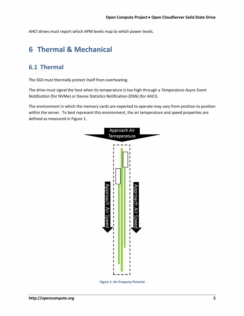
The environment in which the memory cards are expected to operate may vary from position to position
within the server. To best represent this environment, the air temperature and speed properties are
defined as measured in Figure 1.
Figure 1: Air Property Pictorial
6 February 25, 2015
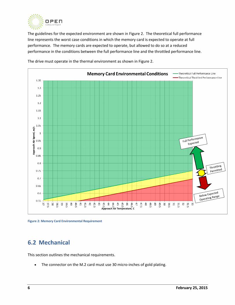
The guidelines for the expected environment are shown in Figure 2. The theoretical full performance
line represents the worst case conditions in which the memory card is expected to operate at full
performance. The memory cards are expected to operate, but allowed to do so at a reduced
performance in the conditions between the full performance line and the throttled performance line.
The drive must operate in the thermal environment as shown in Figure 2.
Figure 2: Memory Card Environmental Requirement
6.2 Mechanical
This section outlines the mechanical requirements.
The connector on the M.2 card must use 30 micro-inches of gold plating.
Open Compute Project Open CloudServer Solid State Drive
http://opencompute.org 7
The server can mechanically support module lengths of 60mm, 80mm or 110mm and uses a
Socket 3 connector.
The card shall conform to the geometry provided by the PCI Express M.2 Specification, section
2.3.4.4, card type 22110.
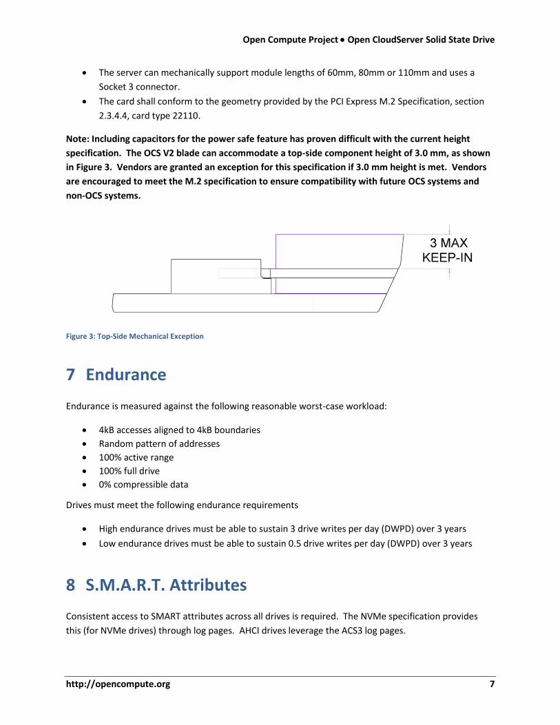
Note: Including capacitors for the power safe feature has proven difficult with the current height
specification. The OCS V2 blade can accommodate a top-side component height of 3.0 mm, as shown
in Figure 3. Vendors are granted an exception for this specification if 3.0 mm height is met. Vendors
are encouraged to meet the M.2 specification to ensure compatibility with future OCS systems and
non-OCS systems.
Figure 3: Top-Side Mechanical Exception
7 Endurance
Endurance is measured against the following reasonable worst-case workload:
4kB accesses aligned to 4kB boundaries
Random pattern of addresses
100% active range
100% full drive
0% compressible data
Drives must meet the following endurance requirements
High endurance drives must be able to sustain 3 drive writes per day (DWPD) over 3 years
Low endurance drives must be able to sustain 0.5 drive writes per day (DWPD) over 3 years
8 S.M.A.R.T. Attributes
Consistent access to SMART attributes across all drives is required. The NVMe specification provides
this (for NVMe drives) through log pages. AHCI drives leverage the ACS3 log pages.
8 February 25, 2015
SMART commands may not block IO for more than 30ms.
SMART values will be updated before each read so that the value reported is the most current.
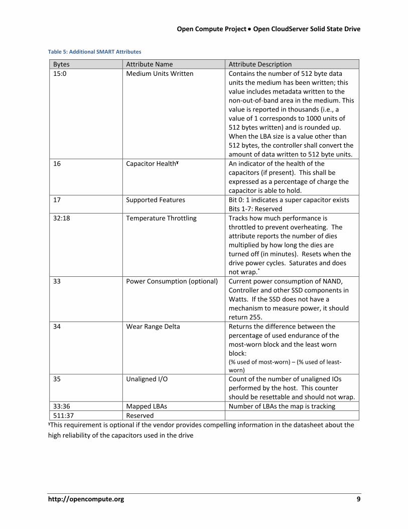
The vendor-specific log page should be 512 bytes and define the following attributes:
Open Compute Project Open CloudServer Solid State Drive
http://opencompute.org 9
Table 5: Additional SMART Attributes
Bytes Attribute Name Attribute Description
15:0 Medium Units Written Contains the number of 512 byte data units the medium has been written; this value includes metadata written to the non-out-of-band area in the medium. This value is reported in thousands (i.e., a value of 1 corresponds to 1000 units of 512 bytes written) and is rounded up. When the LBA size is a value other than 512 bytes, the controller shall convert the amount of data written to 512 byte units.
16 Capacitor Healthˠ An indicator of the health of the capacitors (if present). This shall be expressed as a percentage of charge the capacitor is able to hold.
17 Supported Features Bit 0: 1 indicates a super capacitor exists Bits 1-7: Reserved
32:18 Temperature Throttling Tracks how much performance is throttled to prevent overheating. The attribute reports the number of dies multiplied by how long the dies are turned off (in minutes). Resets when the drive power cycles. Saturates and does not wrap.*
33 Power Consumption (optional) Current power consumption of NAND, Controller and other SSD components in Watts. If the SSD does not have a mechanism to measure power, it should return 255.
34 Wear Range Delta Returns the difference between the percentage of used endurance of the most-worn block and the least worn block: (% used of most-worn) – (% used of least-worn)
35 Unaligned I/O Count of the number of unaligned IOs performed by the host. This counter should be resettable and should not wrap.
33:36 Mapped LBAs Number of LBAs the map is tracking
511:37 Reserved
ˠThis requirement is optional if the vendor provides compelling information in the datasheet about the
high reliability of the capacitors used in the drive
10 February 25, 2015
8.1 NVMe NVMe drives must support the following attributes and logging
Attributes listed in section 5.10.1.2 of the NVMe specification.
Vendor-specific log page 0xC0, as defined in Table 5.
8.2 AHCI
AHCI drives must support the following Device Statistics log pages (defined in ACS3) through the Get Log
command
General Statistics log page
Solid State Device Statistics log page
General Error Statistics log page
Transport Statistics log page
Temperature Statistics log page
AHCI drives must support the vendor-specific log page 0xa0, as defined in Table 5.
9 Commands
The drive must support the commands specified in the NVMe 1.1a and SATA specifications, and must
also operate with the Microsoft drivers included with Windows since version 8.1 / Windows server 2012
R2.
9.1 Firmware Update
NVMe drives must implement firmware updates according to the process defined in the NVMe
specification. The device must support a minimum of 2 slots for firmware update and may support up
to 7.
AHCI drives must use the “download microcode” command and its sub-commands (as defined in ACS3):
3 – Segmented download and 7 – complete download.
9.2 Disk Reconditioning Tool & Crypto-Erase
The following commands are necessary to return the OCS SSD as close as possible to Fresh-Out-of-Box
(FOB) shipping state. FOB includes resetting all FTL state relating to block-mapping tables and garbage
collection logic and erase all stale or invalid data from the flash.
Open Compute Project Open CloudServer Solid State Drive
http://opencompute.org 11
The drive must encrypt all data, and the secure erase command must operate quickly by simply erasing
the key. NVMe supports secure erase setting of Cryptographic Erase (see section 5.13 Figure 111 for
more info).
NVMe drives must return to FOB state after combination of Format NVM and Crypto-erase
AHCI drives must support the Sanitize Device feature set and the CRYPTO SCRAMBLE EXT
command.
9.3 Debugging Logs
The drive must provide access to its debugging logs. The logs should contain enough information to
determine root cause. Their format will be vendor specific with the vendor providing a tool to consume
the logs.
AHCI drives must support the General Purpose Logging (GPL) feature set. The log is retrieved
through the Current Device Internal Status Data log page (0x24)
NVMe drives will use a Microsoft-specific log to access debugging logs.
10 Unplanned Power Loss
This section details requirements for behavior of write cache due to unplanned power loss.
High endurance drives must have a non-volatile write cache
Low endurance drives may have a volatile write cache
10.1 Drives with Volatile Write Cache
A drive with a volatile write cache is one whose data, in DRAM and/or SRAM, is not guaranteed to be
written to non-volatile media on loss of power.
10.2 Drives with Non-Volatile Write Cache
The following types of media are defined as non-volatile caches:
volatile media (such as DRAM and SRAM) protected by capacitance
non-volatile media
drives supporting the PCIe reset Non-Volatile assist signal
If the drive uses volatile media and capacitor health is compromised, the cache is no longer considered
nonvolatile, and the drive must disable the volatile write cache and alert the host.
12 February 25, 2015
NVME drives must alert the host to failed capacitors through the Device Reliability Async event.
AHCI drives must use the Device Statistics Notification from the Device Statistics log page.
10.2.1 System-Assisted NV Write Cache
In this scenario, drives must flush all data to non-volatile storage within 1s of the PCIe reset (PERST)
signal. System voltage will be valid for at least 1s after PERST is asserted. After receiving the PERST
signal, the SSD must not drive any pins.
With this sequence of signals, the drive must not lose or corrupt any user data or metadata, and should
not require self-contained hold-up capacitance. Once the whole-system solution is in place, we will
consider drives supporting this behavior for PCIe reset as having a non-volatile write cache.
10.2.2 Fast Flushing
The performance of drives with non-volatile write caches should not be noticeably degraded by flush,
and the PLP-backed cache(s) should enable fast performance.
FUA – forced unit access (for AHCI only) should be fast
Flush Cache should not degrade performance
SET FEATURE write-cache disable
The drive should still flush data to flash when the drive has been idle for at least 20ms or power has
failed. The host must be able to dynamically disable these performance optimizations.
11 Data Security
The drive must implement the subset of TCG protocol methods described in Microsoft’s Encrypted Hard
Drive Device Guide (called the “eDrive” standard). Microsoft has published the requirements on MSDN:
http://msdn.microsoft.com/en-us/library/windows/hardware/br259095.aspx
Drives must follow the eDrive security standard.