Embed Size (px)
DESCRIPTION
Open hole composite
Citation preview

NASA-CR-t94603
/M _ (/'-CM
EFFECT OF IMPACT DAMAGEAND OPEN HOLE ON COMPRESSIVE STRENGTH
OF HYBRID COMPOSITE LAMINATES
by
Dr Clem Hiel, Research ScientistDivision of Engineering
The University of Texas at San AntonioSan Antonio, TX 78249
(NASA-CR-194603) EFFECT OF IMPACT
DAMAGE AND OPEN HOLE ON COMPRESSIVE
STRENGTH OF HYBRID COMPOSITE
LAMINATES FinB| Report, 1Jun. 1992
- 31Mdy 1993 (Tex_s Univ.) 77 p
N94-16836
--THRU--
N94-Io837
Unc|as
G3/24 0191357
Prepared for NASA Cooperative Agreement NCC2-724Period: June 1, 1992 - May 31, 1993
CONTENTS
I Effect of Impact Damage and Open Hole on CompressiveStrength of Hybrid Composite Laminates
II Appendix: Papers published during grant periodJune 1, 1992- May 31, 1993
- Low and High Velocity Impact Response ofThick Hybrid CompositesProceedings of the American Society for Composites,Seventh Technical Conference, pp 1149-1159, Oct 1992
- Damage Tolerance of a Composite Sandwich withInterleaved Foam Core,
Journal of Composites Technology & Research,Fall 1992, pp 155-168
- Composite Sandwich Construction with Syntactic foamCore,
Composites, Volume 24, Number 5, 1993, pp 447-450
6 October, 1993
Effect of Impact Damage and Open Hole on Compressive Strength
of Hybrid Composite Laminates
Clement Hiel 1
NASA Ames Research Center, Moffett Field, California, 94035
Abstract
Impact damage tolerance is a frequently listed design requirement for composites
hardware. The effect of impact damage and open hole size on laminate compressive
strength was studied on sandwich beam specimens which combine CFRP(*)-GFRP(**)
hybrid skins and a syntactic foam core. Three test specimen configurations have been
investigated for this study. The first two were sandwich beams which were loaded in pure
bending (by four point flexure). One series had a skin damaged by impact, and the second
series had a circular hole machined through one of the skins. The reduction of compressive
strength with increasing damage (hole) size was compared. Additionally a third series of
uniaxially loaded open hole compression coupons were tested to generate baseline data for
comparison with both series of sandwich beams.
(*) CFRP : Carbon Fiber Reinforced Plastic
(**) GFRP : Glass Fiber Reinforced Plastic
1 Research Scientists, NASA cooperative Agreement NCC 2-724 with Division of Engineering at the
University of Texas at San Antonio. (Prof. H.F. Brinson Principal Investigator)
It wasconcludedthatpost-impactstrengthof sandwichskinscanbepredictedby usingan
openholeanalyticalmodelinwhichtheobserved(measured)damagesizeisusedasinput.
Theresultsrevealthesamedependencyof strengthon-damagesize (or holesize)for bothsandwichbeamseries.This canbe attributedto the local natureof the impactdamage
within theskin.Suchdamageis typicallyobservedinsandwichbeamswith syntacticfoam
core.Thebaselinedatafor sandwichskincouponsindicateslowerstrengthascomparedtosandwichdatafor thesameholesize.
The useof anempirical-analyticalprocedureto predict the residual strength of impacted
sandwich beams, based on open hole skin laminate analysis and test data for uniaxial
loading, leads to conservative strength predictions. The higher post-impact performance of
sandwich beam skins, as compared to skin coupons, is attributable to the lateral skin
support provided by the structural syntactic foam which prevents global- and micro
buckling induced-failure modes.
INTRODUCTION
Impact damage tolerance is a frequently listed design requirement for composites
hardware. The success of composite materials applications in secondary loaded structures,
combined with its potential for primary structures has spurred intensive research programs
aimed at integrating materials into hybrid-, damage tolerant-structural configurations.
It can be generally stated that the damage tolerance of structural composite materials is
low, in comparison to (homogeneous) metals. Especially composites with thermoset
matrix are sensitive to stress concentrations due to surface cuts, notches, holes, impact
damage and other material or geometric discontinuities which promotes crack-initiation
and -propagation. Unlike to homogeneous materials, fiber reinforced composites are
significantly more notch sensitive in compression than in tension. This is due to the
development of tensile stresses which are, in the vicinity of a notch or free edge, acting
perpendicular to the fibers and to the lamina. Another major reason is the formation of
2

delaminationdue to impact,which enhancessublaminatebuckling mechanismsunder
compressiveloading.Most of the researchwork aimedat ranking different composite
materials,basedon their damagetoleranceperformancehas beenmotivated by CAI
("Compression After Impact" type of testing
The effect of lateral impact on composite laminates can as a first approximation be looked
at as a hole (only when damage is localized). Early studies on the effects of holes and other
geometric discontinuities in composites have been based on Lekhnitski's classical
analytical solution for the stress distribution in anisotropic plates [1,2]. Follow-up studies
have concentrated on the effect of hole size on the strength of laminated composites under
uniaxial tension and compression [3,4].
Numerous analytical and empirical studies have dealt with parametric effects, such as
stacking sequence or material composition on compressive strength and stability of open
hole specimens [5-12]. These investigations have been motivated by two major objectives:
The first was to provide a database and analytical models for design and prediction of the
mechanical performance of bolted (or pinned) composite joints. The mechanical behavior
of fastened composite joints was investigated extensively during the last decade [13-17].
The information available to date on bearing stresses at the hole contour as well as stress
distribution in the vicinity of the hole provides the data required for strength assessment
and optimized composite joint design [18]. The second objective was to assess the effect of
damage (mainly due to lateral impact) on the residual compressive strength of structural
composite elements. Attempts to use the open hole model to predict impact damage effects
on composite residual strength, on the other hand, were not so successful [19-21 ]. This is
mainly due to the highly complicated geometric pattern, and the mixed multiple failure
mode characteristics which are typical for impact damage in most composite material
laminates [22-26 ]. Multiple delaminations of different shapes and sizes are dispersed

randomlythroughoutthe laminatewidth andthickness.This is combinedwith extensive
matrix- and inter-fiber cracksand with fiber fractures.Furthermore,the compressive
strengthof impactdamagedlaminatesis mainly controlledby a sublaminatebuckling
mechanism[27-30].Suchfailurecharacteristicscouldhardlyberepresentedby thesimple
andwell definedopenholegeometry.Similarcommentsmaybe relevantfor the caseof
impactdamagedcompositesandwichpanelswith honeycombcores[31-33].
This reportprovidesadditionalinformationon thedamagetoleranceandresidualstrength
predictionof a newstructuralconfigurationwhichwasdevelopedby theauthors[34,35].
This compositesandwichsystemutilizesa syntacticfoam corewhich hasconsiderably
morestrengthandstiffnessascomparedto thecommonpolymericfoams.This systemis
able to sustain significant flexural loadingas comparedto thin laminateswhich are
designedsolely for in-planeloading.Additionallytheperformanceof compositesandwich
panelswith syntactic foam core hasbeenproposedas the basic building block for a
compositecompressorblade[35,36]. It wasshownthat in suchsandwichconstruction,
damageis locally confinedwithin a well definedboundaryandmaythereforebe treated
like anopenhole.This isattributedto the localenergyabsorptioncapacityprovidedby the
syntacticfoam core [37]. This appliedcompositestechnologyprogramhashadso much
bite thatit hasdrawninterestfrom acrossthegeneralconsumerproductsector.
Threedifferent testconfigurationshavebeencomparedin this report.The first two were
sandwich beams which were loaded in pure bending (four point flexure). For one series
the skin was damaged by impact, and for the second, a circular hole was carefully
machined through one of the skins. The reduction of compressive strength with increasing
damage (hole) size was compared. Additionally a third series of uniaxially loaded open
hole compression coupons were tested to generate baseline data for comparison with both
series of sandwich beams.
4

Thethreemainobjectivesof thepresentresearchwere:
1. Experimentallyverify the applicabilityof an openhole model for the predictionof
residualstrengthafterimpact.
2. Comparethe compressivestrengthof laminatesandwichskins with open holes by
loading a sandwichbeamin pure flexure with the compressivestrengthof uniaxially
loadedskincoupons.
3. Developanempirical-analyticalprocedurewhichcanbeutilizedto predictthe residual
strengthof impactdamagedsandwichbeamsunderflexure,basedon a simpleopenhole
skin laminateanalysisandtestdatafor uniaxialloading.
Theinformationin this report has been organized in four sections. The first describes the
basic materials used to build the test samples, and their material properties. The second
section details the three test configurations, which were compared in this study, and the
associated test procedures. The third section gives the test results and organizes the
obtained experimental results for interpretation. Additionally, an empirical-analytical
model is discussed which can be utilized for predictive purposes. The fourth and last
section lists three conclusions which are supported by this research.
MATERIALS AND PROPERTIES
The structural configuration, proposed by the authors, is shown in Figure 1. These
sandwich beams were cut from larger panels to a length of 355 mm (14") and a width of
76 mm (3"). The overall thickness is about 34 mm (1.34"). As indicated in Figure 1, the
sandwich beam consists of five different basic materials for which more details and
properties are given below.
Materials

The Core (1) for the sandwich specimens was made of precast syntactic foam (SYNTAC 350)
supplied by Grace Syntactic Company. It consists of epoxy resin filled with glass micro balloons
having the average density of 0.6 gr./cm 3.
The skin laminate consists of a central Carbon Fiber Reinforced (CFRP) laminate (2), layers
of glass weave on both sides of the skin, and film adhesive (3) to intimately bond the glass
weave to the center laminate. The central CFRP laminate, was fabricated from unidirectional
carbon fiber reinforced Bismaleimide prepreg tapes (rigidite G40-600/5245C) supplied by BASF.
It consists of 18 plies, with .14 mm (.005") average ply thickness, and with a (0/+30/-30)3s lay-
up. Two layers of glass fabric reinforced epoxy (GFRP) (4) prepregs (7781/5245C) were
placed above and below the CFRP laminate for external protection of the skin. Two layers of
FM300 prepreg adhesive film (made by American Cyanamid corp.) were placed between the
CFRP laminate and the GFRP.
The skin laminate, with a total of 22 plies, was cured at 177°C (350°F) in a press with heated
platens, following the so called "standard 350 F cure cycle" as supplied by the prepreg
manufacturer. The measured average thickness of the cured skin laminate was 2.52 mm (.099").
The adhesive used to bond the skins to the core was a Hysol EA9394 room temperature
curable adhesive (5). The sandwich beam obtained, as shown in Figure 1 has also been
referred to by the authors as a "Thick Hybrid Composite" (THC).
Material Properties
The basic material properties of the cured, unidirectional CFRP lamina, the GFRP fabric, the
syntactic foam, and the adhesive layers are given in Table 1. They are designated for the cured
state at room temperature (RT.) dry condition. Most of the constituents' data was obtained from
the available literature and supplier information. The properties of the syntactic foam were
obtained independently following ASTM test standards ( D638 for tensile properties, C365 for
compressivestrengthandC273for shearproperties). Most of theCFRPskin propertieswere
computedbasedon the respectivelaminainputs,usingcompositelaminateanalysis,exceptfor
the compressivestrength(Ftc)andthecoefficientsof thermalexpansion (at, a 2) which were
obtained experimentally.
TEST CONFIGURATIONS AND PROCEDURES
Figure 2 gives an overview of the three test configurations, which were used for this study.
This section contains a description and the test procedure for all three configurations.
Series 1: Impact damaged sandwich skin laminates; The upper skin of a sandwich
beam flexural test configuration, which was shown in Figure 1 and discussed above, was
impacted by using a low velocity (drop weight) instrumented impact system. After the
impact, there remains a visible indentation with a diameter D which depends on the impact
energy. The impact test machine has a maximum drop height of 3 meters (9.8 feet) and is
commercially known as the Impac 66 test machine made by Monterey Research
Laboratories. The impactor is a 16 mm (.625") diameter hemispherical (hardened steel) tip
attached to a rigid base with the assembly weighing 86N. The impactor is raised to the
required height by a chain winch which is driven by an electric motor. Two lubricated
circular columns guide the impactor during its fall. Subsequently the weight is released
pneumatically and impacts the test-sample. The rebound of the impactor is arrested
automatically by a braking system to insure a single impact event. The values of the
impact variables were defined experimentally to account for the friction during falling.
The velocity was determined by measurement of the elapsed time between two photo cells.
The actual maximum kinetic impact energy just before the collision was calculated from
this velocity. The average calculated drop acceleration was about 0.88g. The dynamic
response of the system during the impact process was monitored by an H.P. Dynamic
Signal Analyzer (type 3562A) An Endevco type 2252 accelerometer was attached to the
7

top of the impactor.The impactedsandwichbeamspecimensweresimply supportedon
two rollershavingaspanof about200mm(8") asindicatedinFigure3.
After impactthe visibledamagesizealong thebeamwidth andthe damagedepthwere
measured.Subsequentlythedamagedsanwichbeamswere loadedto failure in a 4-point
flexure set-upasillustratedin Figure4. The loadingconfigurationputs the sidewith the
damagedskin in compression.A constantcross-headspeedof 1.84mm/min (.07"/min)
wasmaintainedduringthis test.
Series2: Open hole sandwich skin laminates; were obtained by pre drilling one of the
skins in the sandwich beam configuration (Figure 1) before bonding it onto the core. Hole
diameters in this case varied between 3.05 and 22.2 mm (.12" and .87").
The residual strength was obtained by using the four-point bend procedure, which now put
the side with the hole in compression. The cross-head speed was the same as for series 1
(1.84 mm/min or .07"/min).
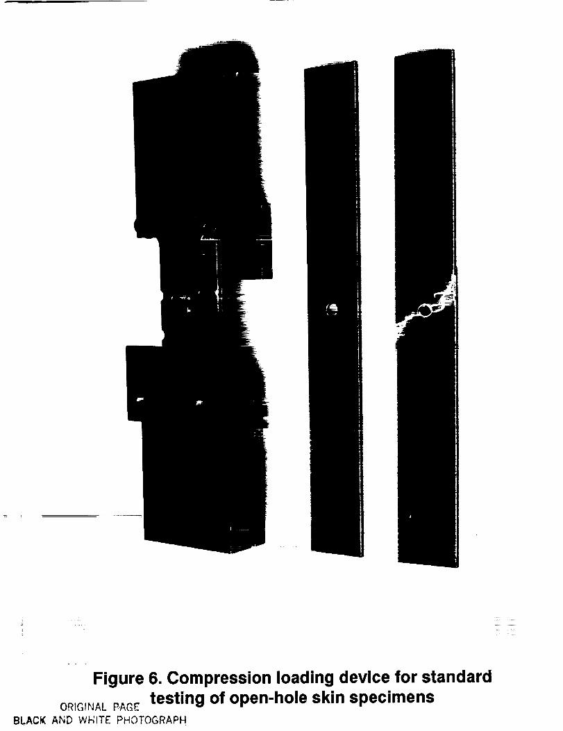
Series 3: Open hole skin coupon laminates; These coupons were obtained by utilizing
only the skin laminate. The test procedure followed the SRM 3-88 (SACMA
recommended method 3-88) which is detailed in reference [38].The special SACMA SRM
3-88 compression fixture is shown in Figure. 5. The test method is based on NASA RP
1092 [39]. Specimen dimensions were 38.1 x 305 mm (1.5" x 12") and the hole diameters
(D) varied from 1.5 to 11.1 mm (.06" to .44") as shown in Figure 5. Specimens without
hole for determination of reference compressive strength data were prepared and tested
according to SRM 1-88. The special test fixure is shown in Figure 6. The test method is
based on ASTM D695. Respective dimensions were 12.7 x 80.8 mm (.5" x 3.18") as
shown in Figure 14c. [40].
8

In both tests, specimens were loaded to failure in compression at constant cross head speed
of 1.27 mm/min (.05"/min)
TEST RESULTS
Most of the test results deal with the effect of damage (or hole) size on laminate strength.
Due to the complex and different hybrid compositions involved in the present
investigation, strength data obtained for sandwich skin laminates (series 1 & 2) and for
skin coupon laminates (series 3) could only be compared by referring to the maximum
stresses at failure (crcf_m,x) acting on the same material phase (the CFRP laminate in this
case). Stress distributions through the different phases of the skin coupon are shown in
Figure 7. The stress tr x shown on the left hand side is the average axial compressive stress
which is obtained by dividing the load at failure by the cross-sectional area. The stress
distribution shown on the right hand side in Figure 7 accounts for the stiffness contrast
between the carbon phase and the glass phase. Therefore, as indicated, the stress in the
carbon is ct times higher than the average stress. A value for a =1.45 was obtained by
laminate analysis. The stress level O-xcf in the carbon phase at skin coupon failure is
considered representative for the in-situ compressive strength of the CFRP laminate.
Figure 8 shows the stress distribution in the sandwich skin laminate. Here the correction
factor y converts the maximum compressive stress O'ef which is obtained from simplified
sandwich analysis to a stress ?r_f, which is the accurate maximum compressive stress on
the carbon phase at skin failure. A value for y .882 has been found for the basic sandwich
configuration by substituting the dimensions specified in Figure 8 and the material
properties found in Table-1 into a laminate analysis program.
The test results for all three configurations, which are reported below, give the stress in the
carbon phase at skin failure. An interpretation of these results is given subsequently.
9

Series1: Impact damaged sandwich skin laminates;
Impact damage characteristics: As was mentioned before, impact damage of a sandwich
with syntactic foam core is local and well confined within a zone which is approximately
circular. This zone can be inspected easily due to a damage induced indentation and a
white imprint at the GFRP fabric coating as shown in Figure 9. The boundary of this
imprint is a good representation of the internal non- visible CFRP damage zone beyond
which the skin may be considered as non-damaged as can be seen by the cross sectional
view of the local damage shown in Figures 10 and 11. Hence, the transverse measure of
this imprint was defined as damage size to be compared to the open hole diameter in test
configuration 2. The damage size seems to be directly related to the increase of the impact
energy, as shown in Figures 11 and 12. Similar results were obtained in another study [35]
for sandwich beams with interleaved syntactic foam core. Additionally this trend was also
demonstrated for the case of sandwich beams subject to high velocity (ballistic) impact
tests [36].
Effect of damage on residual strength : Nominal Compressive Strength was obtained
from the flexural test results of impact damaged sandwich beams. Nominal Strength is
defined here as the maximum skin stress per unit nominal cross-sectional area
(disregarding the presence of damage) at sandwich failure. Increase of the damage size
causes a pronounced deterioration effect on nominal strength for the small damage size
range shown in Figure 13. For larger damage sizes this effect becomes less and less
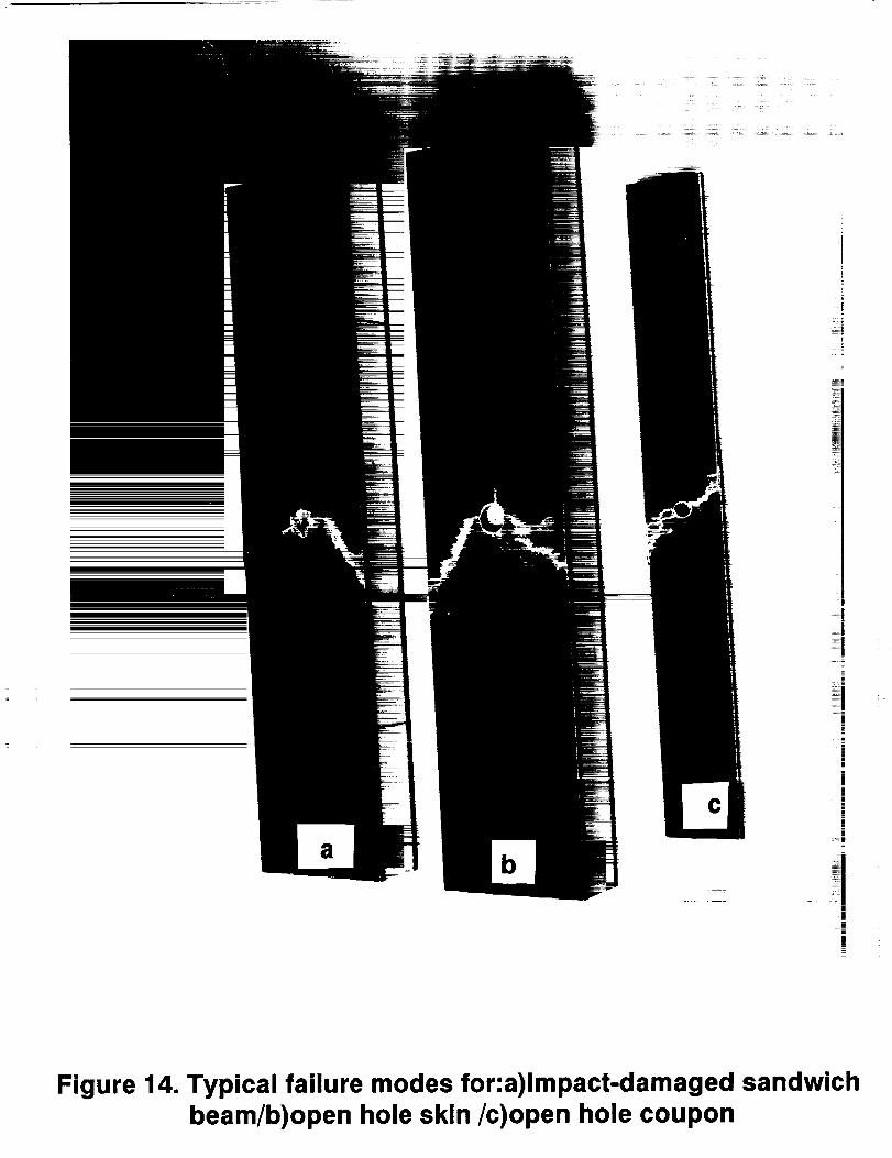
significant. Shear failure, originating from the damage boundary, following the fibers at
the 30-deg angle was seen as the controlling failure mode. (Shown in Figure 14a). Similar
results were also found in earlier studies for the case of sandwich beams subject to high
velocity (ballistic) impact tests [41].
Series 2: Open hole sandwich skin laminates;
i0

The relationshipbetweenNominal CompressiveStrengthand hole diameter,shown in
Figure 15, was obtainedexperimentallyfrom four point flexure testson open hole
sandwichbeams.Thedatawasseento follows atrendsimilarto thatobservedin Figure 13
for the post- impact sandwich specimens.
The observed failure mode, shown in Figure 14b, was also similar. It may therefore be
concluded, at this stage, that damage size definition for the post-impact sandwich is
justified and that the effect of impact damage on residual strength can be evaluated based
on respective open hole sandwich data and analysis.
Series 3: Open hole skin coupon laminates;
The relationship between Nominal Compressive Strength and hole diameter, shown in
Figure 16 was obtained experimentally from uniaxial compressive tests on open hole skin
coupon specimens. The data follows a trend similar to that obtained for series #1 and #2
except that the strength degradation rate is higher, especially in the small hole diameter
range. The observed failure mode, shown in Figure 14c was found to be similar to the one
observed for series #1 and #2 sandwich beam specimens i.e, predominantly shear failure
along 30-deg fiber orientation at the CFRP laminate. This failure mode is also similar to
that for virgin specimens, which was shown earlier in Figure 6.
INTERPRETATION
A. Analytical background
The analytical formulations which were developed in references[2, 3 & 41] for the
prediction of open hole compression strength will be used to examine the experimental
results and to provide analytical tool for prediction of post-impact strength of sandwich
beams based on damage size measurements. This is justified in light of the well defined
11

localized impact damage which was found to be typical for the sandwich having syntactic
foam core in the present investigation. According to this model the compressive stress at
failure, crr_ is a function of the hole diameter (D) and the specimen width (W) as shown in
Figure 17.
As indicated in Equation 1, the notched strength (which is experimentally measurable) can
be obtained by dividing the strength of an infinitely wide laminate by a correction function
Y
oO
(1)trN -Y(D/W)
The correction function can be calculated as follows
2 -I-(1 -D/W) 3YD/W -
D
3(1 -_)
(2)
Strictly speaking this equation is only correct for isotropic laminates and therefore Y is
called the "isotropic width correction factor". Gillespie et al [42] have shown nevertheless
that the above expression is applicable to orthotropic laminates for D/W values smaller
than .25, which was the case in this investigation.
According to Whitney and Nuismer [3] the notched strength of an infinitely wide
orthotropic plate is related to the unnotched strength by the following equation;
with
2o- 0 1-_
-3o¢'-¢](3)
D (4)2j -D+2a i
12

with i=sfor thesandwichskin
i=c for theskincoupon
and
K_ =1 +_/2 _ / E, -Vxy +Ex/2Gxy (5)
Equation 1. was originally used to predict the variation of tensile strength due to a through
the thickness hole (or notch) in a multi-ply laminate. The parameter a i was introduced to
represent a distance, chracterizing the damage zone in the highly stressed region adjacent
to the hole. The distance is used as a free parameter to be determined by fitting
experimental data assuming an average stress over the damage zone. This criterion has
been extended to include compression loaded laminates by Nuismer and Labor [4]. Two
damage size-parameters have been used for the present investigation a_ for the sandwich
configurations and a c for the coupon configuration.
B. Comparison of the effect of impact damage with that of an open (drilled) hole.
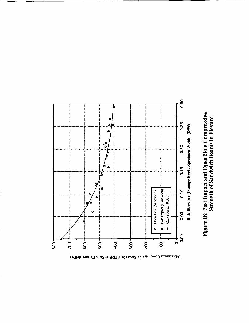
The residual strength data which was shown in Figures 13 and 15 is replotted in Figure 18
as a function of the ratio of damage (open hole) size (D) and specimen width (W). The
data for both series of flexural test beams show a similar dependence on D/W. The
experimental results were therefore represented by a single curve, using the analytical
open hole model of Equation 1, with a_ = 9.3 ram. as the curve fitting parameter.
This result indicates that the use of an open hole model for the prediction of post-impact
compression strength is justified for the present case. It also means that the damage size
(D) is the only parameter required and that the impact history (impact velocity, energy,
load, etc.) does not need to be known to make quantitative residual strength predictions.
This latter point is also substantiated by earlier findings [33,35].
13

C. Comparison of the effect of open holes in sandwich skins and skin coupons
laminates.
The stress at failure of unnotched samples was used to normalize the strength data
obtained on the two different specimen geometries used in test series #2 and #3. Figure 19
compares this normalized stress at failure as a function of the normalized hole size (D/W),
which was also used to represent the data in Figure 18. Similar trends of strength loss with
increasing D/W can be observed. The general trend appears to be that the sandwich skins
lose their strength more gradually than the skin laminate coupons.
The respective analytical plots based on Equation 1 reveal two different empirical
parameters; a higher one for the sandwich skin ( as=9.3mm ) and a lower one for the skin
coupons (ao=2.7mm) The parameter a_ may have a physical significance by quantifying
the stress distribution shape and its singularity level and may be a measure of notch
sensitivity. Hence, based on comparing the a values in the two cases it may be concluded
that sandwich skins are much less sensitive to open-hole and impact damage as compared
with skin laminates.
D. Net Strength Comparisons
The Net Strength (NS) is defined as the load carrying capacity of the material that remains
in the cross section of the skin material after part of it has been taken out by impact or
drilling. It's advantage is that local stress concentration effects can now be compared as a
direct function of the damage size or hole diameter (D). This was done in Figure 20 for the
"Normalized Net Strength" (NNS). Changes in NNS for sandwich skins were only minor
for values of D above 4 mm (.16"). A continuous decrease in NNS is noticeable for skin
coupons with values of D up to 10 mm (.39").
Additionally a Normalized Net Strength Loss (NLS) variable may be derived from NNS
(NSL= 1-NNS). It is plotted as function of hole diameter for both cases (Figure 21 ).
14
The sandwichskins,with NSLmax=26%,clearlyhavea substantiallybetterperformance
thantheskincouponswith NSLmax--42%.
Thebetterresidualcompressivestrengthof damaged (open-hole) sandwich skins (in-situ)
as compared with the respective performance of skin coupons is attributable to two
possible reasons:
1) The presence of a supportive structural core stabilizes the skin resistance against a
compressive sub-laminate buckling mechanism [43].
2) The presence of the core induces in-plane bi-axial compressive stress state in the skin
which may improve its axial strength. [44,45].
CONCLUSIONS
An experimental investigation was conducted on three test configurations; two series of
sandwich beams (post-impact and open-hole) loaded in flexure and a series of uniaxially
loaded open-hole laminated coupons with the same composition as the sandwich skins.
The test results and analytical consideration lead to the following conclusions:
The assumption that the localized impact damage, which is typical for sandwich
construction with syntactic foam core, can be modeled as an open hole is justified.
Engineers can therefore calculate the post impact strength of sandwich skins based on a
simple open hole analysis model, in which the observed (measured) damage size is used as
input.
- The residual compressive strength of post-impact and open-hole sandwich skins show a
similar dependency on damage (hole) size. This can be attributed to the local nature of the
15
impactdamagewithin the skin, as is typically observed in sandwich beams with syntatic
foam core.
- The baseline data for sandwich skin coupons indicates lower strength as compared to
sandwich data for the same hole size. Normalized Compressive Strength for open-hole
sandwich skins and for laminate skin coupons follows a similar trend with increasing hole
diameter.
- The Net Strength Loss (NSL) (derived from net stress at failure) is significantly higher
for open-hole skin laminate coupons than for its sandwich skin counterparts.
-The higher performance of open hole (or impact damaged) sandwich skins is attributable
to the better resistance of the skin to compressive sub-laminate buckling and to the biaxial
state of stress in the skin, both effects which are due to the presence of the syntactic
structural foam core.
ACKNOWLEDGMENT
The author would like to thank Dr. Howard Nelson, Roy Hampton, and Dave Chappell of
the test Engineering and Analysis Branch at NASA Ames Research Center for their
support and encouragement and to Paul Scharmen of the Model Development Branch at
the Center for the high-level manufacturing of the specimens. Additionally, the
contributions of Mike Luft in keeping track of the experimental data and making plots are
greatly appreciated.
16

References
[1] Lekhnitskii, S. G., " Anisotropic Plates " translated from the second russian edition
by Tsai, S.W., and Cheron, T., Gordon and Breach Science Publishers, New York.
1968, pp. 171-190. Original publication in russian, 1957.
[2] Savin, G.N., " Stress distribution around holes" Translated from russian, NASA 'rT
F-607,1970, pp. 227-324. Original publication in russian, 1968.
[3] Whitney, J.M., and Nuismer, R.J., "Stress fracture criteria for laminated composites
containing stress concentrations". J. of Composite Materials Vol. 8 July 1974, pp.
253-265.
[4] Nuismer, R.J. and Labor, J. D., " Application of the average stress failure criterion:
Part II - Compression," J. of Composite Materials, Vol. 13, Jan. 1979, pp. 49-60.
[5] Sun, C.T. and Lao, J., " Failureloads for notched graphite/epoxy laminates with a
softening strip, " Composite Science and Technology," Vol. 27, 1985, pp. 121-133.
[6] Lubowinski, E. G., Guynn, W. E., and Whitcomb, J. D., "Loading rate Sensitivity of
open hole composites in compression," NASA TM 100634, August 1988, 30p.
[7] Guynn, E. G. and Bradley, W. L., "A detailed Investigation of the micromechanisms
of compressive failure in open hole composite laminates," J. of Composite
Materials," Vol. 23, May 1989, pp. 479-504.
[8] Guynn, E. G. and Bradley, W. L., Measurments of the stress supported by the crush
zone in open hole composite laminates loaded in compression," J. of Reinforced
Plastics and Composites, Vol. 8, March 1989, pp. 133-149.
[9] Larson, Per-Lennart, " On buckling of orthotropic stretched plates with circular
holes," Composite Structure, Vol. 11, 1989, pp. 121-134.
[10] Lin, C.C. and Kao, C.S., "Buckling of laminated plates with holes," J. of
Composite Materials, Vol. 23, June 1989, pp. 536-553.

[11]
[13]
[14]
Chang,F. K. andLessard,L. B., "Damagetoleranceof laminated composites
containinganopenholeandsubjectedto compressiveloadings:PartI--Analysis," J.
of Composite Materials, Vol. 25, Jan. 1991, pp. 2-43.
[12] Lessard, L. B.and Chang, F. K., "Damage tolerance of laminated composites
containing an, open hole and subjected to compressive loadings: Part II:
Experimental," J. of Composite Materials, Vol. 25, Jan. 1991, pp. 44-64.
Chang, F. K., Scott, R.A. and Springer, G. S., "Strength of Mechanically Fastened
Composite Joints," J. of Composite Materials, Vol. 16, Nov. 1982, pp.470-494.
Chang, F. K. and Scott, R.A., " Failure of composite laminates comntaining pin
loaded hole-method of solution," J. of Composite Materials, Vol. 18, May 1984,
pp. 255-289.
[15] Mahajerin, E. and Sikarskie, D. L., "Boundary element study of a loaded hole in
an orthotropic plate," J. of Composite Materials, Vol. 20, July 1986, pp. 375-389.
[16] Tsujimoto, Y. and Wilson, D., "Elasto-plastic failure analysis of composite bolted
joints," J. of Composite Materials, Vol. 20, May 1986, pp. 236-252.
[17] Erikson, I., " On bearing strength of bolted graphite/epoxy laminates," J. of
Composite Materials, Vol. 24, Dec. 1990, pp. 1246-1269.
[18] Tsai, S. W., "Composite Design" Fourth Edition, Think Composites: Dayton,
Paris, and Tokyo. 1988, Section 18.
[19] Williams, J. G. "Tough Composite Materials; Effect of impact damage and open
holes on the compression strength of tough resin/high strain fiber laminates." NASA
Conference Publication 2334, 1984, pp 61-79
[20] Chamis, C. C. and Ginty, C. A., " Fiber composite structural durability and
damage tolerance: Simplified predictive methods", ASTM STP IOI2, 1989, pp. 338-
355.

[21] Jegley, D. C., "Compression behavior of graphite-epoxy and graphite-
thermoplasticpanelswith circular holes or impact damage"NASA Conference
Publication3087Part2, 1990,pp.537-558.
[22] Hsi-Yung T.W. and Springer, G. S., " Measurmentsof matrix cracking and
delaminationcausedby impactoncompositeplates"J. of Composite Materials, Vol.
22, June 1988, pp. 518-532.
[23] Hsi-Yung T.W. and Springer, G. S., " Impact induced stresses, strains, and
delaminations in composite plates" J. of Composite Materials, Vol. 22, June 1988,
pp. 533-560.
[24] Lesser, A. J. and Filippov, A. G., " Kinetics of damage mechanism in laminated
composites" 36th International SAMPE Symposium, April 1991, pp. 886-899.
[25] Starnes, J.H. and Williams, J. G., Failurecharacteristics of graphite-epoxy
structural components loaded in compression" NASA Technical Memorandum
84552. 1982, 24 p.
[26] Chai, H. and Babcock C. D., "Two-dimensional modelling of compressive failure
in delaminated laminates", J. of Composite Materials, Vol. 19, Jan. 1985, pp. 67-98.
[27] Marshall, R. D., Sandorff, P. E. and Lauraitis, K. N., "Buckling of a damaged
sublaminate in an impacted laminate" ASTM J. of Composite Technology &
Research Vol. 10, No. 3, Fail 1988, pp. 107-113.
[28] Ishai, O. and Shragai, A. " Effect of impact loading on damage and residual
compressive strength of CFRP laminated beams", Composite structures, Vol. 14,
1990, pp. 319-337
[29] Shalev, D. and Reifsnider, K.L., "Study of the onset of deIamination at holes in
composite laminates", J. of Composite Materials, Vol. 24 Jan. 1990, pp. 42-71.
[30] Soutis, C. and Fleck, A.F., " Static compression failure of carbon fiber T800/924C
composite plate with single hole", J. of Composite Materials, Vol. 24, may 1990,
pp. 536-558.
[31] Gottesman,T., Bass,M. and Samuel,A., "Critically of Impact Damagein CompositeSandwichStructure," 6th InternationalConferenceof CompositeMaterials,Vol. 3, 1988,
pp. 327-335.[32] Sommers, M., Weller, T., and Abramovich, H., "Influence of predetermined
dalaminationsonbucklingbehaviorof compositesandwichbeams,"Composite Structures,
Vol. 17. 1991, pp. 292-329.
[33] Kim, C. G., AND Jun, E. J., " Impact resistance of composite laminated sandwich plates",
J. of Composite Materials, Vol. 26, No. 15, 1990, pp. 2247-2261.
[34] Abrate, S. "Impact on laminated composite materials", Appl. Mech. Rev. Vol. 44, No. 4
April 1991.
[35] Ishai, O., and Hiel, C. "Damage tolerance of a composite sandwich with interleaved foam
core," ASTM J. of Composite Technology & Research JCTRER, Vol. 14, No. 3, Fall 1992,
pp. 155-168.
[36] Hiel, C. and Ishai, O., "Design of highly damage-tolerant sandwich panels," 37th
International SAMPE Symposium, March 1992, pp. 1228-1242.
[37] SACMA Recommended Test Method for Open-Hole Compression Properties of Oriented
Fiber-Resin Composites. Recommended method, SRM 3-88.
[38] Standard Tests for Toughened Resin Composites Revised Edition, NASA Reference
Publication 1092, July 1983, 35 pages.
[39] SACMA Recommended Test Method for Compressive Properties of Oriented Fiber-Resin
Composites. Recommended Method, SRM 1-88.
[40] Whitney, J.M. and Guihard S. K. " Failure modes in compression testing of composite
materials," 36th International SAMPE Symposium, April 1991, pp. 1069-1078.
[41] Daniel, I. M., " Behavior of graphite/epoxy plates with holes under biaxial loading,"
Experimental Mechanics, Vol. 20, No. 1, Jan. 1980, 8 pages.
[42] Daniel, I. M., "Biaxial testing of [02/+45]s graphite/epoxy plate with hole," Experimental
Mechanics, Vol. 22, No. 5, may. 1982, 8 pages.
[43] Gillespie,J.W., and Carlson, L.A., "Influence of finite width on notched laminate strength
predictions," Composites Science and Technology, Vol 32, 1988.

List of Captions
Detailed description of non-damaged (Virgin) sandwich beam configuration.
Illustration of specimen configurations for the different test series
Flexural test set-up.
Fi__ig_.4 • Low velocity Impact test set-up:
Compression Loading device for standard testing of virgin skin specimens.
Compression Loading device for standard testing of open-hole skin specimens.
Stress Distribution and formulation for hybrid skin laminate under uniaxial compression.
Stress Distribution and formulation for hybrid sandwich beam under flexure.
External damage imprint on sandwich skin due to low velocity impact loading.
Fig. 10 :SEM of Typical Cross-section with low velocity impact damage (Impact energy: 90J )
_: Micro graphs of cross-section of sandwich specimens damaged under different levels
of impact energies
Fig. 12; The effect of low velocity impact energy on visible damage size of sandwich beams
with syntactic foam core.
Fig. 13: The effect of damage size on Nominal residual strength of post-impact sandwich
(series 1).
Fig. 14: Typical failure modes for: a) Impact-damaged sandwich beam under flexure
b) Open-hole skin of sandwich beam under flexure
c) Open-hole skin coupon under uniaxial compression.
Effect of hole diameter on nominal strength of open-hole sandwich specimens (series 2).
Fig. 16: Effect of hole diameter on nominal strength of open-hole skin coupons (series 3)
Fig. 17: Open-hole model and formulation for prediction of compressive strength.
Fig. 18: Comparison of impact damage and open hole effects on residual strength of sandwich
beams.
Fig. 19; Comparison of open-hole size per unit width effects on normalized nominal compressive
strength for sandwich beams vs. skin coupons.

Comparisonof theeffectof open-holesizeonnormalizednetcompressivestrengthfor
sandwichbeamsvs. skincoupons.
Fig. 21" Comparison of the effect of open-hole size on net compressive strength loss for
sandwich beams vs. skin coupons.


<_,-_
/
0
C• . ,._ 0
0Wi(
8
v1 i 0
"l-
eeo0
0 0
0 0
g_dW
<
0
0_m
_m
L
=om
=
el,i_

.lie
E
el
E
o_
el
i
J
0
0
E
em
ee

H
r
_o
H
°_,_©
_ 0
• . _
_ °°
|
rj_
c_
E
om
m
olml

!-. '
It©
2_
|
m

Figure 5. Compression Loading device for standard
testing of virgin specimen ORIGINALP-A_BLACK AND WHITE PHOTOGRAPH
"i"ii;ii ¸ ;_ _
Figure 6. Compression loading device for standard
OmGrNALPAGEtesting of open-hole skin specimensBLACK AND WHITE PHOTOGRAPH

II II II
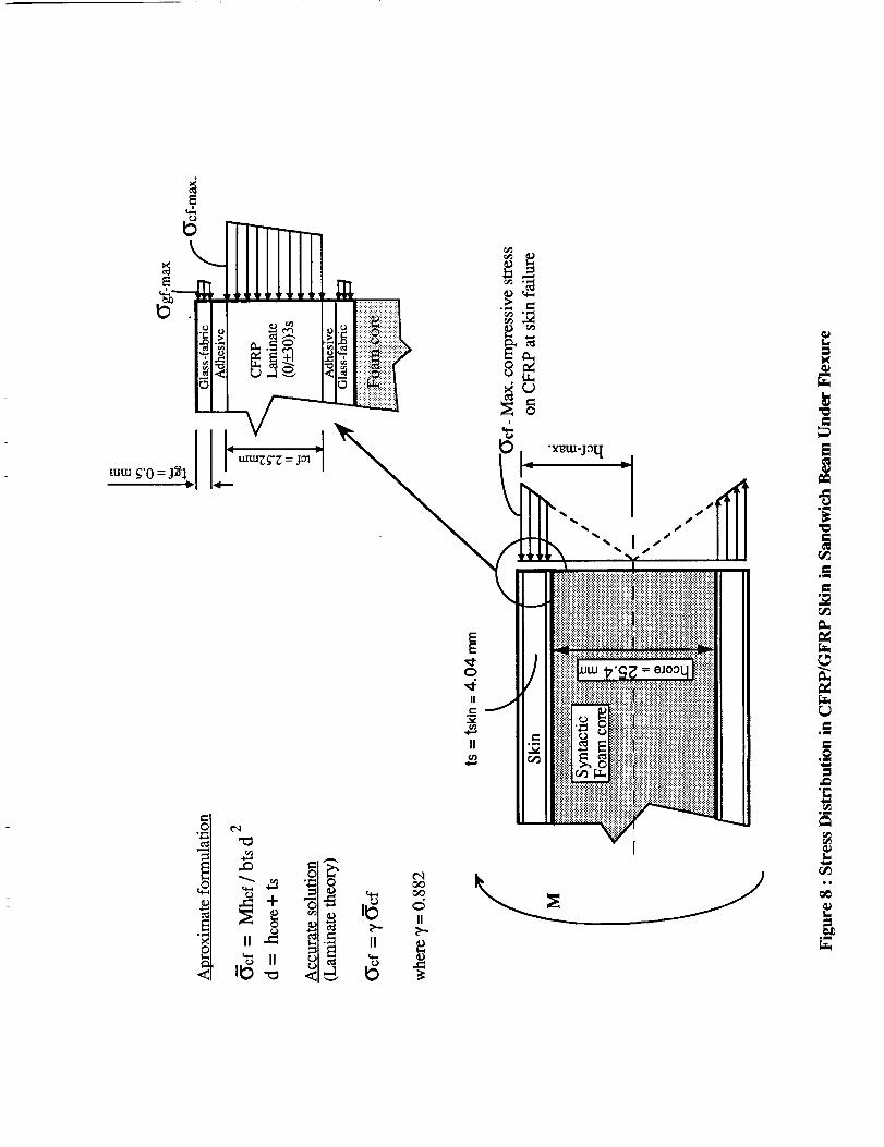
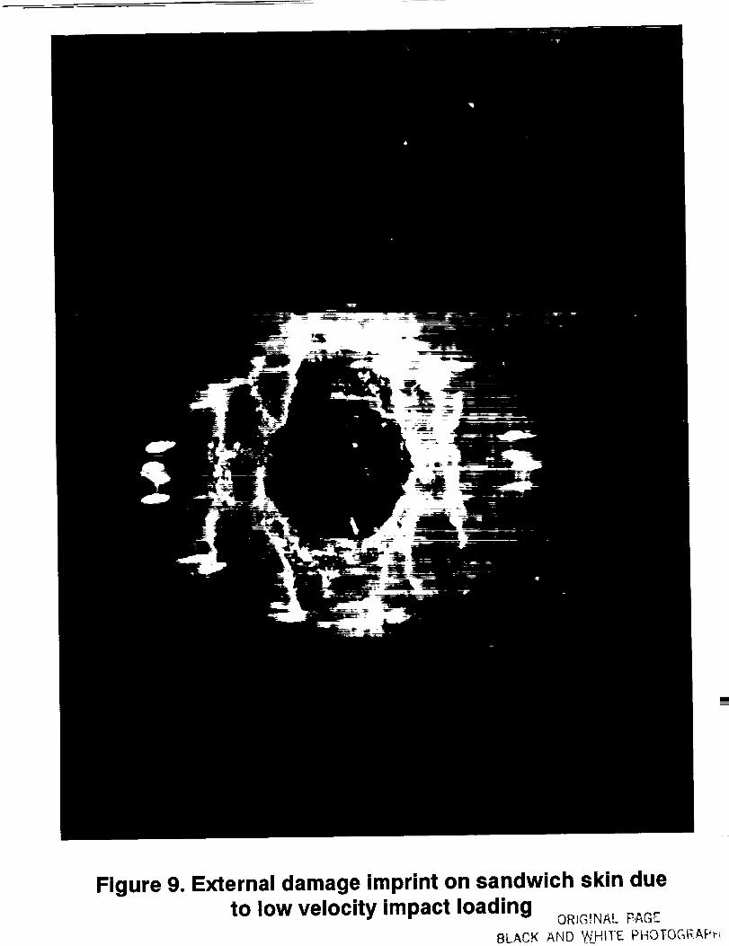
Figure 9. External damage imprint on sandwich skin due
to low velocity impact loading OmG_NAL_:AGr_BLA,.,K AND WHITE PHOTOGR.AP_-_

I IORtG,NA,. PA_
BLACK AND WHIt"E PHOTOGRAPH
Figure 10. SEM of typical cross section with lowvelocity impact damage (impact energy=90 J)

47 J (34 ft-lb)
69 J (51 ft-lb)
90 J (67 ft-lb)
136 J (100 ft-lb)
180 J (132 ft-lb)
Figure 11, Micrographs of cross-section of sandwich specimensdamaged under different levels of impact energy

,¢.. COx--
0
k0T.-
IO,I,r-
05 ¢D t_ O
O
7_
OO0T.-
O
v--
i..
O
¢.D
Q
O
.=
_J
Ol
z-
*mm
(ram) _zis oSt_mEfl _lqISIA

8 8 8 8 8 8 8 8 o
Q0
a_
o_
,m
J
_._.
0
e_
O
(gdIA[) _Jn!!_l q_!A_puus _u ss_lS _A!SS_Jdmo_) leu!moN[ U!_lS "X_l_
I
!
i
|i||ii
i|
Figure 14. Typical failure modes for:a)Impact-damaged sandwichbeam/b)open hole skin/c)open hole coupon

0
o o o _ ° _
(_dlA[)oJnl!_I q_!_pu_s _ ssoJ_S OA!SSOadmoD l_u!moN u!_IS "x_IA/
Q
T.-
¢Xls.-
0
Im
0
m
om_
C,d
emm
o
I
r_2
oo
k_

0
o//
w-¢
om
8 8 8 8 8 8 _ 8o
o
(VdIAI) osnl.t¢_l upls _ ssoJ1S OA!SsoJdmo_) IBu!moN "X_IA[

X
Y
D
Figure 17 : Open Hole Model and Formulation forPrediction of Compressive Strength.
0ooo
/00
0 I I
1 ood
0 0 0 0 0 0 00 0 0 0 0 0
or..)*.=
l
0
_m
(gdIAL) oanp._I m._iS lv d_I_ID u! ssoalS aA!ssoadmoD mnm!xvIAI

0
¢
.L
_0 rle_
............................. i_/_.............. _ ........
C_
d
0 • ! II
I V eo _ d o o
_Jnp.e_l u_s _v d-H_ID u! ssoJ_ S _A!SS_Jdmo D lvm.mol_ P_..igm.mNI
_.--
r_
=
e_
_"cl°_
_r.f)
ee
f_
oU

u oJ
0
0
0 em
,- d d d d d
EE
!......... i ........
0
0 •
i
l oo o o o d
C;
Noi
0
°_
=o_
oJnl.tUd upis l_ d_l_I_3 u.t ssoJ_S OA!SsoJdmo_) 1_H POZt.lumJoH
_ o• 0
o
CD
0
0
0
T-
OO • 0
)
o
• _o
o
emm
i
o
=
(%) ssol q_uo_S oA!ssoJdmoD _oN

II Appendix
Papers published during grant periodJune 1, 1992- May 31, 1993

PROCEEDINGSOF THEAMERICAN SOCIETYFORCOMPOSITES
SEVENTH TECHNICAL CONFERENCE
COMPOSITE MATERIALS, MECHANICS AND PROCESSING
Co-Sponsored by
PENNSYLVANIA STATE UNIVERSITY
THE COMPOSITES MANUFACTURING TECHNOLOGY CENTER
and
BOEING HELICOPTERS
October 13-15, 1992
Keller Conference Center
University Park, Pennsylvania
IECHNOMICPUBLISHINGCO., INC
[ ,ANCASTER • BASEL

N94-16837
Low and High Velocity Impact Response of
Thick Hybrid Composites
C. HIEL AND O. ISHAINASA Ames Research Center
MS 213-3Moffett Field, CA 94035
ABSTRACT
The effects of low and high velocity impact on thick hybrid composites
(THC's) were experimentally compared. Test Beams consisted of CFRP skins
which were bonded onto an interleaved syntactic foam core and cured at 177°C
(350 °F). The impactor tip for both cases was a 16 mm (0.625") steel hemisphere.
In spite of the order of magnitude difference in velocity ranges and impactor
weights, similar relationships between impact energy, damage size, and residual
strength were found. The dependence of the skin compressive strength on
damage size agree well with analytical open hole models for composite
laminates and may enable the prediction of ultimate performance for the
damaged composite, based on visual inspection.
NOMENCLATURE
aoc : Free parameter in Average Stress Criterion for compression.
Ex : Young's modulus in x-direction.
: Young's modulus in y-direction.
v,y : Poisson's Ratio.
G, : Shear Modulus.
KT : Stress Concentration Factor for Infinite Width.
R : Hole Radius.
W : Sandwich Panel Width.
1i49
PRECEDING PAGE BLANK NCT F}LI_ED

1150 THICK COMPOSITES
Y : Finite Width Correction Factor.
ON : Unnotched Strength.
oN :Notched Strength for Infinite Width.
_n : Notched Strength.
INTRODUCTION
Extensive research on carbon-epoxy laminates has clearly shown that
these materials can only accommodate impact energy by developing internaldamage which is mainly in the form of a delamination failure mode. The
residual compressive strength performance is therefore severly impaired, and
may limit the use of these laminates to secondary structures. An additional
drawback is that the damage, in most cases, is not detectable by visual
examination. Publications which compare low and high-velocity impactresponse of laminates are rare. Cantwell and Morton (1989) choose a 6 mm
(0.236") hemisphere to impact Grafil XA-S/BSL914C laminates with thicknesses
varying from 4 to 64 plies. They found that for conditions of low velocity
impact, the size and the shape of the target determines its energy absorbing
capacity and therefore its impact response. High velocity impact loading induces
a localized form of target response and the level of damage incurred does not,
therefore, appear to be governed by the areal size of the component. They
further concluded that high velocity impact loading by a small projectile is
generally more detrimental to the integrity of a composite structure than low-
velocity drop-weight impact loading. Moon and Shively (1990) choose a 12.7
mm (0.5") hemisphere to impact 48 ply laminates made of AS4-1806, AS4-934,
and IM7-855I-7 prepregs respectively. Their findings were similar to thosereported by Cantwell and Morton.
A more comprehensive literature review, on damage tolerance of
composites in general was published by Abrate (1991) and by Ishai and Hiel(1992).
Traditionally, sandwich constructions consist of three main parts; two
thin, stiff and strong skins separated by a thick, light, and weaker core. The skins
are adhesively bonded onto the core to enable load transfer between the
components. Composite sandwich construction has been found to be a very
efficient way to utilize composite laminates and is therefore used extensively
and very successfully in industry. Until recently, the main emphasis was on
secondary structural components which require high strength and highstiffness-to-weight ratios. Several damage tolerance studies have been conducted
on sandwich constructions having carbon-epoxy skin layers and honeycomb or
lightweight foam core. Nevertheless, to the best of the author's knowledge, no
work was found that compares the low and high-velocity impact response of

Low and High Velocity Impact Response of Thick Hybrid Composites 1151
sandwich panels with a structural (syntactic) foam core. This type of material is
subsequently referred to as a thick hybrid composite (THC).
Studies on the impact response of THC's have recently been performed
(Ishai and Hiel 1992). This paper discusses the relevant details on fabrication, the
experimental conditions for low and high-velocity impact, and the inspection
and characterization of the impact damage. The relationship between damage
size and residual strength is represented by an analytical model. The paper closes
with a comparison of the effect of impact energy on the residual strength for
both low and high-velocity impacts.
MATERIALS AND FABRICATION
An illustration of the thick hybrid composite is shown in Figure l a. It
consists of the following components:
1. A skin laminate, composed of 18 plies of prepreg
(G40-600/5245C) with a (0/+30/-30)3s layup.
2. An external layer for skin protection, composed of two
glass fiber fabric 7781/5245 C prepreg layers.
3. A layer of FM300 adhesive.
4. A layer of 7781/5245 C prepreg at +45/45orientation.
5. Three layers of syntactic foam (Syntac 350).
The fabrication is as follows: First, the layers of syntactic foam core are cut.
Then the different parts, shown in figure la, are laid-up into an aluminum
mold. After the layup is completed, the mold is closed, vacuum bagged and
transferred to a press with heated plattens. The whole assembly is subjected to a
350°F cure-cycle after which it is demolded.
It should be noted that this fabrication process has great technological
significance since it is also applicable to sandwich constructions with complex
geometries because the foam can be cast into any desired shape.
Sandwich beams, with dimensions shown in figure lb, were cut from the
sandwich panel using a diamond tipped bandsaw. The edges were then polishedwith a diamond coated sander.
IMPACT LOADING
Low velocity Impact
Low velocity impact tests were conducted using a conventional
dropweight test rig. An 86 N (19.3 lbs) impactor with a 16 mm (0.625")
hemispherical tip was allowed to fall freely from heights ranging from 0.30 m (1

1152 THICK COMPOSITES
ft) to 2.13 m (7 ft) thereby creating impact velocities ranging from 2.4 m/sec (7.9
ft/sec) to 6 m/sec (19.7 ft/sec). The sandwich beams were simply supported withthe distance between the supports being 0.203 m (8").
High Velocity Impact
High velocity impact tests were performed using an airgun. Air with a
pressure up to 1.03 Mpa (150 psi) was fed to a chamber. At this point the air was
restrained by a plastic diaphragm. When the pressure in the chamber reached a
pre-determined value, a small electric current, passed through a piece of
resistance wire located at the center of the diaphragm precipitated its ruptureand the release of the air. The rapid expansion of the air accelerated a
sabot/projectile combination along the length of the 1.79 m ( 70" ) barrel. Upon
reaching the end of the barrel, the sabot is stopped by a tapered tube (sabot-
catcher) allowing the 17 gram (0.04 Ibs) projectile to continue free flight and
strike the simply supported sandwich beam. The terminal velocities obtained
ranged from 40 m/sec (130 ft/sec) to 160 m/sec (525 ft/sec). The velocity wasmeasured by digital clocks which were activated by trip wires located at three
locations in the barrel. Both the impactor and the sandwich beams had the same
geometry as in the low velocity impact tests.
DAMAGE INSPECTION AND CHARACTERIZATION
The design of the sandwich panels allowed for the extent of damage to be
easily differentiated by visual inspection. It was observed that any low or high-
speed impact causes a localized damage and delamination of the surface layer ofglass-epoxy. The circular delamination is easily visible in both cases and
therefore sophisticated NDT equipment is not needed for an initial damage
assessment. Cross sectional cutting through the damaged zone was routinelyconducted to relate the observed surface- damage and the actual delamination
between the skin and the core. Figure 2 indicates that the low velocity impactcauses an indentation while the tangential elastic displacements of the contact
surfaces cause the formation of a cone crack. Figure 3. is representative for a
high-velocity impact with the same energy (and for the same shape of the
impactor). The permanent indentation induced by the low speed impactor
appears to be deeper than that induced by the high speed impactor at the same
impact energy. Aditionally, there is substantially more delamination present in
the case of high velocity impact. In summary one can state that the impactedskin of a THC at low velocity, as shown in Figure 2. is very similar to the
impact damage inflicted on thermoplastic laminates (Starnes and Williams
1983). The impacted skin of a THC at high velocity, as shown in Figure 3.hasdamage which is very similar to that infliced on thermoset laminates. It is
therefore likely that rate dependence of stiffness and strength in the z-directionneeds to be introduced in future mathematical models for THC's.

Low and High Velocity Impact Response of Thick Hybrid, Composites 1153
Further evaluation of the damage mechanism is obtained by relating the
damage size to the impact energy as shown in Figure 4. As can be seen, damage
caused by both low and high-velocity impacts have a similar dependence on the
energy. Final conclusions cannot be formulated at this time, because the damage
caused by high velocity impacts has more scatter at the higher impact energies.
Following damage characterization, the sandwich beams were subject to
four point bending. The distance between the supports was chosen as 0.33 m
( 13" ) with a distance between the loads of 0.076 m (3"). Each THC was loaded
with the damaged skin on the compressive side. Strength was defined as theSkin Stress at Failure (SSF).
RESIDUAL STRENGTH
The low and high-velocity impact damage was localized, and is therefore
expected to have only a limited effect on the beam stiffness. They act, however,
as stress raisers and can therefore have a significant effect on laminate strength.
This is evident from figure 5, where the residual strength is plotted as a function
of damage diameter. Again it can be seen that there is basically no difference
between reduction in strength due to low and high-velocity impacts. The solid
curve was obtained by using the Whitney-Nuismer (1974) average stress failure
criterion which leads to the following Equation:
O'N= Y(2R / W)
which states that the notched strength (which is experimentally measurable) can
be obtained by dividing the strength of an infinitely wide laminate by a
correction factor Y, which is can be calculated as follows;
Y(2R/W)=
strictly speaking, this equation is only correct for isotropic laminates and
therefore Y is called the "isotropic finite width correction factor". Gillespie et al
(1988) have shown nevertheless that the above expression is applicable to
orthotropic laminates for d/W values smaller than .25, which was the case in
this investigation.
According to Whitney and Nuismer (1974) the notched strength of an
infinitely wide orthotropic plate is related to the unnotched strength by the
following equation;
1154 THICK COMPOSITES
2o'o(1-¢)
= ÷ 3)(¢'-¢')]
with
R
R+a._
and
Kr=l+ 2 Ex -
The equations were originally used to predict the variation of tensile
strength due to a through the thickness hole (or notch) in a multi-ply laminate.
The quantity aoc was introduced to represent a characteristic damage zone in the
highly stressed region adjacent to the hole. The distance is used as a free
parameter to be determined by fitting experimental data assuming an average
stress over the damage zone. This criterion has been extended to 'include
compression loaded laminates by Nuismer and Labor (1979).
Our basic assumption in using the described analytical approach to THC's,
is that the impact damages material over a radius R, and that this material no
longer participates in the load transfer process within the laminate. Therefore
the damaged material can effectively be tought of as nonexistent and be
considered-as a hole with radius R. The parameter aoe for the present data was
found to be 6.09 mm (0.24"), which is very close to the result obtained by
Nuismer and Labor (1979) on a carbon'epoxy laminate.
Figure 6 relates the residual strength to the impact energy, and shows that
both the low and high-velocity data can be merged onto a single master curve. It
may therefore be concluded that impact energy is the single most important
factor to control residual strength reduction of structural sandwich panels with
interleaved core (provided the same impactor tip is used).
CONCLUSIONS
O Damage size was found to be similar for both low and high velocity impacts
having the same energy.
O Damage microstructure was found to resemble thermoplastic materials at
low impact velocity and thermoset laminates at high impact velocity.

Low and High Velocity Impact Response of Thick Hybrid Composites 1155
0 Reduction in residual strength is directly controlled by the impact energy,
while impact velocity plays a minor role.
O The Whitney-Nuismer average stress criterion, for open hole laminates,
provides an appropriate presentation of the experimental data which relates
damage size to residual strength.
ACKNOWLEDGMENT
The authors express their appreciation to Michael Luft, Howard Nelson
and Dave Chappell of the Test Engineering and Analysis Branch at NASA Ames
Research Center for their support and encouragement. They also acknowledge
the substantial manufacturing expertise dedicated to this project by Paul
Scharmen of the Ames Modelshop.
REFERENCES
Abrate, S., I991, "Impact on Laminated Composite Materials," Applied
Mechanics Reviews, vol 44, #4, April 1991, pp 155-190.
Cantwell, W.J., and Morton J., 1989 "Comparison of the Low and High Velocity
Impact Response of Sandwich Panels," Composites, Vol. 20, Number 6, pp 545-551.
Freeguard, G.F., and Marshall, D., 1980, "Bullet-Resistant glass- A review of
product and process technology-," Composites, January, pp 25-32.
Gillespie, J.W., and Carllson, L.A., (1988) "Influence of Finite Width on Nothced
Laminate Strength Predictions," Composites Sdence and Technology, 32.
Hiel, C., and Ishai, O., 1991"Low.- and High-Velocity Impact Response of
Sandwich Panels with Syntactic Foam Core," Proceedings ASME WinterAnnual Meeting, Atlanta, Ga Dec 1-6.
Ishai, O. and Hiel, C.C., 1992, "Damage Tolerance of Composite Sandwich Panels
with Interleaved Foam Core," Journal of Composites Technology and Research,Vol 14, #3 ,Fall 1992
Masters, J.E., 1987, "Correlation of Impact and Delamination Resistance in
Interleaved Laminates," Proceedings of the Sixth International Conference on
Composite Materials, Eds. F.L. Matthews et al., Vol 3, pp 3.96-3.107.
Moon, D., and Shively, J.H., 1990, "Towards a Unified Method of Causing Impact
Damage in Thick Laminated Composites," Proceedings of the 35-th
International SAMPE symposium.
1156 THICK COMPOSITES
Nuismer, R.J., and Labor, J.D., 1979, "Applications of the Average Stress Failure
Criterion: Part U-Compression," J. Composite Materials, 13: 49-60,.
Starnes, J.H., and Williams, J.G., "Failure Characteristics of Graphite-Epoxy
Structural Components Loaded in Compression," Mechanics of CompositeMaterials-Recent Advances- Hashin, Z., and Herakovich, C.T., Pergamon Press,
1983, pp 283-306
Whitney, J.M. and R.J. Nuismer, 1974, "Stress Fracture Criteria for Laminated
Composites Containing Stress Concentrations," J. Composite Materials, vol 8,
p.253.

.2
3
4,
5 core I
4,
core J
4,
5 co re ]
4, _
2
Fig. l(a) Identification of materials In interleaved sandwich panels
±
Fig. l(b) Principal dimensions of Interleaved beam
Fig. 2 Low.velocity impact damage: cross-sectional view
1157

........ _ --5 ...... \_- ....... -_ • -_-- _-_ ...........
i ...........................................
=--2_Z_ .......... _'21_'2_'Y__............ _" ._52_-_ "-'_ ...................
Fig. 3 High-velocity Impact damage: cross-sectional view
g
.L
20 i
10.
0
PJ
el
G
el
el 4e
elB
el •el
300
Energy-Uf-(J)
Fig. 4 Dependence of damage size on impact energyel low velocity impact• high velocity impact
1158

t
U
oa 01 02 43 o4 o|
o*moge •_e 7 epeeJm4_ wJdqb
I 1 1 III611al__OacI _ N_Om. 17ti'_
( O|Wl 711ram 07i OI O|
Fig. 5 Dependence of residual strength on damage size(normalized by specimen width)
= low velocity Impacto high velocity impact
m
|,..
|
I
im
!
!-| '"
J I ! I IL: CNll ul_m I_t4tl I I_t/Jlfo uIIIIN " IIIN I
--_ ILIII,I_ _ | eepiclu ueqnl. 117111
Cento to lee Oep Nr4_l _ dSll
20 40 ¢_0 8(l ¢06 t20 t40 110 too 200 220
Impeel ee, oql I ¢J|
Fig. 6 Dependence of residual strength on Impact energy
• low velocity Impact
o high velocity impact
1159

Author zed Reprint 1992 from Journal of Composites Technology & Research, FALL 1992Copyright American Society for Testing & Materials, 1916 Race Street, Philadelphia, PA 19103
Ori lshai t attd Clenwnt Hiel 2
Damage Tolerance of a Composite Sandwich with InterleavedFoam Core
REFERENCE: lshai, O. and lticl, C., "Damage Tolerance of a Com-posite Sandwich with Interleaved Foam Core," JournalofCompositesTechnology & Research, JCTRER, Vol. 14, No. 3, Fall 1992. pp.155- 168.
ABSTRACT: A composite sandwich panel consisting of carbon fiber-
reinforced plastic (CFRP) skins and a syntactic foam core was selectedas an appropriate structural concept for the design of wind tunnelcompressor blades. Interleaving of the core with tough intcrlaycrswas done to prevent core cracking and improve damage tolerance ofthe sandwich. Simply supported sandwich beam specimens were sub-jected to low-velocity, drop-weight impacts as well as high-velocity.ballistic impacts. The performance of the interleaved core sandwichpanels was characterized by localized skin damage and minor crackingof the core. Residual compressive strength (RCS) of the skin, whichwas derived from flcxural test, shov,'s the expected trend of decreasingwith increasing size of the damage, impact energy, and velocity. Inthe case of skin damage, RCS values of around 5(1U of the virgininterleaved reference were obtained at the upper impact energy range.Based on the similarity between low velocity and ballistic impacteffects, it was concluded that impact energy is the main variablecontrolling damage and residual strength, where as velocily plays aminor role. The superiority (in damage tolerance) of the compositesandwich with interleaved foam core. as compared with its plainversion, is well established This is attributable to the tougheningeffect of the intcrlayers which serve the dual role of crack arrestorand energ.,, absorber of the impact hmding.
RT
RCS
SSSF
b
d,
EII,E,_,_
Fif,F2t
F_Gt.:
gH
/t
L,,
I
go
w,O[ 1_O{ 2
1)12
Room temperature conditions
Residual compressive strength
Skin maximum compressive stress at sandwich failure
Sandwich width
Impactor diameter
Lamina longitudinal and transverse elastic moduli, re-
spectively
Lamina longitudinal and transverse tensile strength,
respectively
Lamina longitudinal and transverse compressive
strength, respectively
Lamina in-plane shear strength
Lamina in-plane shear modulus
Constant of gravity
Drop-weight height
Sandwich thickness
Sandwich spanSkin thickness
Ply thickness
lmpactor weight
Lamina longitudinal and transverse CTE, respectivcly
l.amina hmgitudinal Poisson's ,atio
KEYWORDS: damage, damage tolerance, impact, ballistic impact.impact velocity, impact energy, sandwich beam, interleaving, syn-tactic foam, residual strength, carbon fiber-reinforced foam
Nomenclature
BVD
CFRP
CTE
DTC
DTE
FRP
GFRP
ttC
Barely visible damage
Carbon fiber-reinfl_rced plastic
Coefficient of thermal expansion
Damage tolerance characteristics
Damage tolerance evaluation
Fiber-reinforced plastics
Glass fiber-reinforced plastic
Honeycomb core
TPrcsently, visiting scientist, NASA Ames Research Center, Mail Stop213-3, Moffctt Field, CA 94035: permanently, professor, Tcchnion-lsraclInstitute of Technology, l laifa, Israel.
:Principle investigator, Composite Material Research Program, NASAAmes Research Center, Mail Stop 213-3, Moffett Field, CA 94035.
g: 1992 by the American Society for Testing and Materials155
Introduction
Composite materials are considered to be good candidvtcs for
replacing metals in helicopter and compressor blades applica-
lions. This is duc to their superior mechanical properties such
as: high strength and stiffness per unit weight, long fatigue life,
durability, and better damage tolerance characteristics (DTC).
The last advantage has been shown to be of major importance
by past failures of aluminum wind tunnel blades. NASA Ames
promoted a research and development (R&D) project It) provide
input data for comparing composites and aluminum dcsign al-
ternatives for wind ttmne] compressor rotor blades. A composite
sandwich structure composed of CFRP skins and foam core was
chosen as an appropriate concept. The effect of impact on dam-
age and consequential residual strength were selected as a major
subject for investigation. At an early stage of the research it was
found that an elevated-temperature-cured sandwich, with a full
depth plain syntactic foam, was highly sensitive to impact load-
ing. This was manifested by extensive cracking of the core and
poor residual strength. To reduce this effect, the core was tough-
ened by interleaving with adhesive and glass/epoxy intcrlayers.
PRE_NG PAGE BLANK NOT FILMED

156 JOURNAL OF COMPOSITES TECHNOLOGY & RESEARCH
The main objective of the prcsenl investigation was to provide
experimental data for damage tolerance evaluation (DTE) of
this complex composite sandwich system.
Damage Tolerance Methodology for Structural Composite
Laminates
Most investigations dealing with DTE are aimed at three main
objectives:
• The assessment of structural performance under static or
cyclic loads or both as well as survivability of structural
elements, which were previously damaged by accidental ina-
pact.
• To provide guidelines and allowables for design and qualityassurance of composite structure_which are likely to sustain
impact damage and where DTE has to be considered.
• Ranking, for material selection purpose, of different com-
posite systems based on their response to impact and their
residual structural performance.
The first issue is of major concern for aircraft industries and
certification authorities. For this purpose, some specifications
and requirements based on DYE have been proposed [I 2]. These
assessments are mainly related to critical levels of impact energy
and damage size. Another DTE classification is defined as "barely
visible damage" (BVD) threshold. Data on carbon-epoxy lam-
inates indicate that at BVD level, compression strength after
impact may decrease to as low as 4()5¢ of the undamaged ref-
erence strength. The respective level of residual compressive
strain seems, nowadays, to be the accepted allowable design limit
for high performance carbon-epoxy composites in structural air-
craft applications. Most investigations that are concerned withmaterial selection are based on several attempts to standardize
DTE testing methods [3,4]. This effort is essential because of
the high sensitivity of the composite to the impact test variables
such as: the impactor diameter, the specimen geometry, and its
boundary conditions [5-71 .
The effect of impact velocity has also been considered. There
is a clear distinction between the low velocity drop-weight test
and the high velocity (ballistic) test as a result of their probable
different effects on damage characteristics [8-10]. The effect of
material composition on DTC can only be evaluated by keeping
a uniform test method. Several investigations that have used the
clamped plate [8,11,12] or narrow beam configurations [13] have
indicated a strong effect of different material parameters on DTC,
namely: variation in layer stacking sequence, using thermoplasticrather than thermoset resin as a matrix, interleaving the laminate
with tougher plies, and so forth. During the last decade, most
of the publications on DTE were limited to composite laminates.
Studies on the effect of impact on damage and residual perform-
anee of substructural elements such as sandwich panels have been
less frequent, possibly as a result of the numerous parameters
and the complexity involved.
Damage Tolerance Evah_ation of Composite Sandwich Panels
Composite skins in sandwich panels subjected to flexural im-
pact behave entirely different than plate laminates mainly for
the following two reasons. First, the skin is under phme axialloads when the sandwich is under flexure, hence, interlaminar
shear stresses are confined mainly to the local impacted zone.
Second, the core provides a relatively soft substrate which locally
may absorb the impact energy. The weak link in sandwiches in
many cases is the core material, which may fail by shear or tensile
stresses induced under flexural impact. Most of the publications
on this topic deal with sandwiches composed of honeycomb core
and CFRP skins. Similar to the DTE of laminates, the evaluation
of sandwiches is treated at three levels, namely: the effect of
fabrication flaws, artificial flaw's, and impact damage.
The following types of flaws as a result _ff fabrication may be
detected: cracks in the core caused by thermal curing stresses,
partial separations at bonded interfaces in the core and between
core and skins, skin transverse cracking, and delaminations. Core
flaws were found to affect sandwich performance as a result of
the reduction in its shear strength and modulus [14,I51. Inter-
facial separation also has a significant effect on strength above
critical debonding length and depends on skin configuration [161.
To enable the evaluation and prediction of the effects of flaw
size and location on the composite sandwich performance, ar-
tificial flaws are inserted into the sandwich structure. Information
from these studies may lead to the definition of flaw criticality
and the related strength which is essential for sandwich design
and quality assurance. In most cases, artificial flaws are embed-ded within one of the skins in a sandwich which is subjected to
flexure or compressive loading up to failure [17,181. Anal}ileal
models are based, in many cases, on the sublaminate buckling
mechanism of delaminated composites [19,20]. It has been claimed
that damage caused by low velocity impact has the most severe
effect on laminate and sandwich performance [1]. Tests con-
ducted on CFRP skin and honeycomb (IIC) core have indicated
that, at BVD level and above, damage is characterized by local
fiber breakage and delamination of the impacted skin [21]. Re-
sidual strength in most cases is below 50fi of the nondamaged
reference. Analytical model predictions gave more conservative
results than experimental data. It was concluded, in other in-
vestigations, that impact energy to failure increases with skin
thickness and its rigidity [22]. Increasing honeycomb density tends
to improve damage tolerance, but cell dinaension has only a
minor effect.
Several investigations dealt with the effect of ballistic impact
when a small diameter impactor was used [23-251. In most cases,
the damage was characterized by combined fiber fiaeturcs and
local internal delaminations. This failure mode may be modeled
as a hole through the skin. Predictions of residual strength, based
on this model, are in good agreement with experimental findings
[261. Investigation into the effect of cyclic compressive loading
[25,27] has indicated that cvcn at BVD level, fatigue life may
be reduced as a result of propagation of dclaminations and in-
terfacial separations which were formed during impact.
Several investigations deal with the effect of impact on sand-withes with different combinations of skin and core materials
such as: aluminum, glass-phenolic and Nomex" honeycombs,
three-dimensional (3-D) fabric, and Rohacell _ foam. Skins, in
most cases, are composed of graphite-epoxy [28-31]. Tests have
shown that by proper selection of core material, adhesive, and
hybridization with tougher fibers, the mechanical properties of
the sandwich may be varied widely with corresponding improve-
ment in impact energy absorption. Recently, attention has shifted
toward attempting to understand and predict the behavior under
impact of basic structural composite elements which are mainly
used in aircraft applications [32,33]. Such studies try to establish
a more standardized DTE approach for structures and provide
guidelines for improving the damage tolerance by proper selec-
tion of materials and composite layup variable.

The Effect of huerleaving
During the last decade, many efforts have been dedicated
toward improving fracture toughness and damage tolerance of
advanced composites with brittle epoxy matrices designated for
elevated temperature applications. A comprehensive review of
this topic [34] summarizes the different techniques, test methods,
and properties of toughened composites. One of the most prom-
ising approaches was the interleaving of the carbon-epoxy lam-
inates by softer and tougher materials such as adhesive films. It
was found that interleaving may reduce interlaminar stresses at
critical locations [35], hereby significantly increasing the inter-
laminar fracture toughness, decreasing and controlling impact
damage, and improving RCS [13,36,37]. This approach was ex-tended to include different interleaving materials such its ther-
moplastic films and hybridization using tougher FRP interlayers
[38-40]. It was also used successfully at the structural element
level [41,42]. To the best knowledge of the authors, the inter-
leaving method hits not been used in conjunction with syntactic
foams. While this is probably a result of the limited application
to date of these foams in high performance sandwich structures,
it is, however, reasonable to assume that the interleaving tech-
nique may significantly improve impact damaging effect and sub-
sequent residual strength of sandwiches composed of these core
materials.
Conchtding Remarks
Based on the above literature review and information on me-
chanics of sandwich structures, the following gcneral comments
may be concluded in relevance with the present investigation:
• The composite skin is the backbone of the slmdwich struc-
ture and provides its strength and stiffness.
• The main function of the core is to support the skins to
awfid local buckling and to absorb energy as a result of local
impact. It must also possess enough strength and stiffnessfor the transfer of shear and tensile stresses under flexural
loading.
• Syntactic foams, which are composed of epoxy resin rein-
forced with glass microballoons, have higher density than
other foams and I tC cores. They possess, however, better
strength and stiffness characteristics as required for high
performance structural sandwich applications.
• Syntactic foams for elevated temperature applications (350°F
[176.6°C1) may be cracked undcr impact loading because of
their relative high brittleness and induccd curing tensile stresses
due to their high coefficient of thermal expansion. Inter-
leaving techniques, which have been proven successful for
composite laminates, offer promise for improving damage
tolerance characteristics of syntactic fimm sandwich struc-
tures.
Objectives
The objectives of thc present research are as follows:
• Study the effect of impact loading on damage and subse-
quent residual strength of composite sandwiches with syn-
tactic foam cores.
• Develop a database for interleaved core sandwich structure
taking into account damage tolerance considerations.
• Investigate the effect of core composition parameters on
DTC to provide design guidelines for optimizing sandwich
postimpact structural performance.
ISHAI AND HIEL ON TOLERANCE OF COMPOSITE SANDWIC H 157
Materials and Specimens
Sandwich structures are usually composed of three main com-
ponents, namely, skins, core, and an adhesive which bonds them
together. In the present case, a fourth phase, the interleaved
layers, is added. All of the constituent materials for the above
components were cured at 177°C (350°F) and are designated to
be used under service conditions of up to 122°C (250°F).
Constituent Materials
The structural skins were fabricated from unidirectional car-
bon fiber-reinforced bismaleimide (CFRP) prepreg tapes (Rigidite
G40-600/5245C) supplied by BASF. Each skin consisted of 18
plies (average ply thickness of 0.14 ram) with the following layup:
(0/+ 30/-30)3_. Two layers of BASF glass fabric-reinforced epoxy
(GFRP) prepregs (7781/5245C) were added for external protec-tion of each skin. The core was made of prefabricated solid
syntactic foam (Syntac 350) supplied by Grace Syntactic. It is
composed of epoxy resin filled with glass microballoons having
the density of about 0.6g/cmL The adhesive used was FM300
prepreg film made by American Cyanamid Corp. The interleaved
phases consisted of one ply of glass fabric prepreg oriented at
+ 45 ° to the beam axis embedded between two plies of adhesive i +
film.
Sandwich Specimens
A typical sandwich specimen configuration with interleaved
core is illustrated in Fig. 1. It consists of two CFRP skins with
the GFRP fabric coating and three foam core layers which are
bonded together with the skins by four interleaves. In the case
of plain core reference specimens, the skins were bonded to the
core with adhesive film (FM300). Sandwich panels were fabri-
cated by cocuring of the skin plies and interleave prepregs to-
gether with the solid core pieces by means of a press-molding
process (under pressure of about 6 atm). Two types of specimens
were cut from the cured panels as follows:
• Long beams of about 350 by 76 b} 30 mm for residual
strength tests.
• Short beams of about 210 by 76 by 30 mm for cross-sectional
damage assessment.
CFRP Skin
_/I/I///I///////I't'//.4
Syntactic _"_'1 _'_ Tough
Foam ,,.t interlayers
core _'__/1/11"//I////I/1."//;
Protective glass-fabric coating j
Plain core sandwich reference
FIG. l -- Typical configuration of composite sandwich with interleavedcore and plain core sandwich reference.

158 JOURNAL OF COMPOSITES TECHNOLOGY & RESEARCH
After rough cutting with a carbide-coated saw, the specimens"
edges ,,,,'ere machined and polished under water by means of a
diamond powder-coated disk to attain smooth and parallel surfaces.
Characteristics of Sandwich Constituents
The basic mechanical properties of the cured, unidirectional
CFRP lamina, the GFRP fabric, the syntactic foam, and the
adhesive layers are given in Table 1. They are designated for the
cured state at room temperature (RT) dry condition. Most of
the constituents' data were obtained from the available literature
and supplier information. The properties of the syntactic foam
were obtained independently following ASTM test standards
(ASTM Test for Tensile Properties of Plastics [D 638], ASTM
Test for Flatwise Compressive Strength of Sandwich Cores
[C 365], and ASTM Test for Shear Properties in Flatwise Plane
of Flat Sandwich Constructions or Sandwich Cores [C 273]). Most
of the CFRP skin properties were computed based on the re-
spective lamina inputs, using composite laminate analysis, except
for the compressive strength (F,.) and the coefficients of thermal
expansion (cq,c_:) which were obtained experimentally.
Test Procedure
A flow chart of the research program and test procedure is
shown in Fig. 2. Accordingly, two identical series of specimens
were subjected to low velocity and ballistic impact loading. After
visual damage assessment, these specimens were loaded in flex-
ure to failure for residual strength determination. Damage tol-
erance characteristics of interleaved and plain core reference
sandwich configurations were evaluated based on the relation-
ships between impact variables and damage characteristics and
between these parameters and residual strength.
Fabrication of I-- I Effect of core I
sandwich specimens I_ / I composition I
Lowvemoeltyt l __1 E.ectofim_ct
I I . sua,.ns.actionofdam , ctdam ge lI I coreandinte"a st 1
°o.,statictes,I- II E.ectotlmpact on damag_ I $ I InterelatiOnsh'ps
,.__] Effect of impact on residual strength _ between damage
_ [ Effect of damage onstrengt_ J 1 [ tCer_ n_e _rial:les_ l
Data base and des gn guide nes for optimal '[__[ Concluslon.s and [
sandwich configuration aiming at improved DTC j - [ tnpu s lor aes0gn
FIG. 2--Scheme of research program and test procedure.
hnpact Testing
Two types of impact tests were designated to represent the
range of impact events which may occur to compressor blades
during installation, maintenance, and wind tunnel operation, they
are commonly defined as low velocity (drop-weight test) and
high velocity (ballistic test), respectively. An illustration and
basic specifications of these tests for the present investigation
are shown in Fig. 3. There is a large difference in impact velocity
and impactor weight between the two tests; however, to get a
reliable comparison between low and high velocity tests the im-
pactor head geometry was kept identical in the two cases.
Drop-Weight Impact Test
The instrumented impact system comprises of a Impact 66 test
machine made by Monterey Research Laboratories. The maxi-
uNri_
MATERIAL
CFRPG40-6005245C
GFRPFabric77815245C
SyntacticFoam350(2
TABLE t--Sandwich con._tituettts properrie._.
ELASTIC PROPERTIES STRENGTH PROPERTIES C.T.E Thick.
GPa MPa C "Ix 10 _ (ram)
El I F_.22 Gt2 V12 Fit Flc F2t F2c 1=6 ill (3.2 t 0
170 11.8 5.2 .33 2070 1380 75 251 102 -.3 28 .14
AdhesiveFM300.08psf
CFRP Skin
(0/'30/-30)3=(**)
30.3 30.3 5.4 .17 374 560 374 560 99 9.9 9.9 .24
2.26 2.26 .84 .31 27 54.6 27
2.45 2.45 .88 .38 53 98 53
54.6 25 48* 48*
98 35 77 77 .26
97.2 14.8 24.5 1.21 936 660 70 289 153 -3.3* 15.1" 2.52
*) Co¢ficient of Thermal Expansion Values were determined experimentally at temperature range of 20-120°C
**) Most of CFRP skin properties were computed based on the respective lamina inputs, except _t, (D. and Fie which were derived experimentally.

ISHAI AND HIEL ON TOLERANCE OF COMPOSITE SANDWICH 159
Low velocity, (Drop weight) set-up
/
ImpactorHeight- H< 2.5m ¢
Impactor Weight- W = Iw
Impactortip diameter-d = 16ram
_111111111111111111111111111111HHH_
l JL
200mm "_
Velocity range : up to 6 m/sec
Energy range : up to 160 J
High velocity (balistic), Air- gun set-up
W = .177 N
v-p _ IB,
d= 16ram
f200ram
Velocity range : up to 160 m/sec
Energy range : up to 220J
FIG. 3--Illustration of .,etup._ for two types of impact tests.
mum tower height is about 3.0 m. The impactor comprises of a
16-mm-diameter hemispherical tip (hardened steel) attached to
a rigid base with the assembly weighing 86 N. The impactor is
raised to the required height by the hydraulic system and released
pneumatically. Its rebound is arrested automatically by a braking
system to insure a single-impact event. During the fall, the im-
pactor is guided by two lubricated circular columns. To account
for the friction during falling, the exact values of impact variables
was derived experimentally. The _,elocity was determined opti-
call)' by measuring the elapsed time between two photo cells.
The actual maximum velocity and the derived kinetic energy just
before the collision arc plotted as functions of the drop height
in Fig. 4 in comparison with the respective predicted curves. The
lower values of the measured velocity and energy variables as
compared to the predicted ones are attributed mainly to frictional
resistance to the falling weight. The average calculated drop
acceleration was about 0.88g. The dynamic response of the sys-
tem during the impact process was monitored by a dynamic signal
analyzer Type 3562A made by Hewlett Packard using accclcr-
ometer Type 2252 made by Endevco which was attached to the
top of the impactor. Most of the impacted sandwich beam spec-
imens were simply supported on two rollers having a span of
about 200 mm. Typical acceleration and the integrated velocity
versus time responses recorded during impact of interleaved and
plain core sandwiches are shown in Figs. 5 and 6, respectively.
The acceleration response in Fig. 5, which is typical for the
7.5
I
Analytical
T0,0
0,0 0,5 1.0 1.5 2,0 2.5
Height [ml
220
200"-- //
180"
t60 /
-"n-140 _
L0. /
80 ......... -_
60 ---- _ ___O' Exlm'tmental40 Analytical
20 / ......
0
0.0 0.5 1.0 1.5 2.0Height [ml
2.5
FIG. 4--Calibration curves of impact variables as function of drop-weight height.

160 JOURNAL OF COMPOSITES TECHNOLOGY & RESEARCH
o h iL
.:---i+-,
+10-2.0 -1,2 -0.4 e 04 1.2 210 2 .0 36
Tim4 (nloc)
4,4 $2 8.0
0.4
0.2 --_ +-
,.O2
_-0.4
_ 4).1t
-I.2-2.0 -t.2 -0.4 ° 0.4
\\
\\
_l L__J
1.2 20 2.g 3.8 4.4 5+2
Tkne 1nl4c)
6,0
FIG. 5--Typical acceleration and velocity response curves fi)r interleaved core sandwich. Recorded during low veloci O'
impact test (input energy." 156 J) (skin damage only)+
" -I__ _____._ --
I i _ ____-I.0 -0.2 0.8 1.4 2.2 3.0 3.8 4+6 5.4 6.2 7.0
Time (m_)
0.rm
0.00v -0.06
I -0,16-O24
-0.32-0.40
\
\
\-0+48
-0.56
-I.0 -O.2" 0.6 1,4 2.2 3.0 3,8 4.6 5.4 6.2 7.0
Time (reset)
FIG. 6--Typical acceleration and velocity response curves for plain core sandwich. Recorded during low velocity impact test (inputenergy: 68.7J) (core damage mainly).
noncracked interleaved core sandwich, shows a tend towards a
minimum (or maximum deceleration) which is not easy to define
quantitatively as a result of the graph fluctuations. The velocity
curve, which is obtained by integration of the acceleration graph,
is smooth and continuous and allows precise determination of
the minimum acceleration from its extreme slope. The difference
between the input impactor velocity and response velocity is used
for computation of energy loss as a result of energy absorbed,
mainly by the skin local damage during the impact process. On
the other hand, the response of the plain core sandwich to the
impact is different (Fig. 6). It is characterized by a highly scat-
tered acceleration graph with no trend at all and a discontinuous
velocity curve attributable to the cracking of the noninterleaved
core during impact. Here, the lower upward velocity after impact
(as compared with the control specimens with the interleaved
core) indicates higher energy loss, mainly due to the failure pro-cess in the sandwich core.
High Velocity (Ballistic) Impact TesO
Ballistic tests were conducted by using an air-gun device. Air
pressure (up to 1.03 MPa) was fed to a chamber in which it was
restrained by a thin plastic diaphragm. At a predetermined pres-
sure level, the diaphragm was ruptured by electrical heating and
the air was released. The abrupt air expansion accelerated a
sabot/impactor combination along the 1.79-m tapered barrel which
caught the sabot at its end. After a short free flight, the 17-g
impactor collides with a simply supported sandwich beam spec-imen. The terminal velocities obtained, which were controlled
by the air pressure, ranged from 40 to 160 m/s. The velocity was
measured by digital clocks activated by trip wires located at three
positions close to the barrel edge. Both the impactor and the
sandwich beam had the same composition and geometry as those
used for the drop-weight, low velocity impact test.
Impact Damage Characterization
After impact loading, each specimen was inspected visually
and the external dimensions of the damage were measured, namely:
the damage size and its depth. In most cases, the damage shape
was close to circular and the average diameter was considered
to be a measure of its size. Maximum damage depth was mea-
sured by a special indicator to an accuracy of 0.01 ram. Different
specimens, representative of the overall impact range, were sec-
tioned through the damage center for internal inspection of the
damage sandwich. Typical photographs of external and internal
damage surfaces for the interleaved specimens are shown in Figs.
7 and 8 and will be discussed later.

ISHAI AND HIEL ON TOLERANCE OF COMPOSITE SANDWICH 161
155._ 115.11
[
|35.6 qg?- I
113.1 83A
'RL3 6_.1,
46.5 34.3
Z-LO 17.7
,,, ............ [
t_.tRI 19.7
558 IS..t
5.1It+ Ih,7
,+57 15.t+
3.2fi Ill. _
FIG. 7--External (top) view of damage for interleaved core sandwichspecimens subjected to different low velocity impact energy levels.
D.IPI_CT DAMAGE IN COMPOSITE SANDWI(7tl PANEI,S
V_TI'II 1NTI(RI.I';AVED FOAM CORE t <'uoss.sl.:<l'mX vlt:w)=
113.1 83.4
68.7
46.5
24.0
50.7
34.3
17.7
5.09
3.96
3.26
2.35
16.7
13.0
10.7
7.7
m'
FIG. 8--Internal (cross-sectional) view of damage for interleaved coresandwich specimens subjected to different low velocity impact energy levels.
Residual Strength Testing
Following external damage inspection, the specimens were
loaded to ultimate failure in four-point flexure using an MTS
test system. In all cases, the sandwich was placed so as to load
the damaged skin in compression. Constant cross-head speed of
1.84 mm/min was maintained during the test. An illustrative
description of the flexural system is shown in Fig. 9. The relevant
values of the skin compressive stress at sandwich failure (SSSF)
and the core shear stress at sandwich failure (CSSF) were derived
from the ultimate load P, value based on the simplified sandwich
beam formulations. A classical sandwich analysis was used for
the derivation of stress formulation given in Fig. 9. It is justified
due to the high stiffness ratio between the CFRP skin and the
interleaved core (above 30).
Skin stress at skin failure (SSSF) is the maximum effective
stress acting on the upper side of the skin laminate cross section
at failure. The SSSF value represents the residual compressive
strength (RCS) of the damaged skin laminate and the residual
strength of the sandwich. The skin laminate is treated here ma-
croscopically as a quasi-homogeneous material under uniaxial
stress loading. The load-deflection relationship was linear to fail-
ure which was catastrophic and brittle. Hence, maximum stress
criterion was found to be adequate.
Test Results
Test results and their evaluation are involved with several
variables and characteristics which may be classified into three
main groups, namely: impact variables, damage characteristics,
and residual strength variables. A detailed list of these variables
is given in Fig. 10.
Impact Damage Assessment
The protective glass fabric-epoxy layers on the external skin
surfaces were found to be highly sensitive to the impact loading
which left clear imprints whose dimensions varied with the impact
magnitude (see Fig. 7). The boundaries of these imprints seems
to be dictated by the contact surface between the impactor tip
and the specimen. The dimensions of internal interfacial de-
bonded area measured from the cross-sectioned specimens (Fig.
8) were found to match approximately the respective external
imprint sizes at all impact levels. It was concluded that this type
of coating may provide an excellent tool for impact damage
inspection and assessment in a real structure, where skin damage
is the predominant failure mode. In all cases, tested skin impact
damage was confined to a well-defined local zone which was
almost circular. The predominant failure modes were transverse
cracking and delaminations which did not propagate beyond the
externally defined damage zone (see Fig. 11). In the case of the
specimens with interleaved core, initiation of core cracking orig-
inating from the skin damage zone could be detected (Fig. 11).
This cracking process seems to be arrested by the internal in-
terleaves which were slightly damaged at high impact levels.
These findings demonstrate the effectiveness of the interleaving
process for either preventing or delaying core failure. In the case
of the plain (noninterleaved) core specimens, cracks developed
through the core depth which were activated by the combined
action of tensile curing stresses and shear stresses induced by the
flexural impact. A typical pattern of such cracking is shown in

162 JOURNAL OF COMPOSITES TECHNOLOGY & RESEARCH
Front view of loaded sandwich beam Cross sectional view
P
I Load Fixture
I = 330 mm
CFRP Skin
f/////////I////ll//tt/////2
Syntactic Foam
I d= h+t2
Approximate sizes (mm)
t=2.5
h = 30(_'max skin ---- Peh / 2btd 2 - Maximumnormaleffectivestress
acting on skinlaminate d = 27I
r_average core = P / 2bd - Averagecore stressshear stress b = 76
FIG. 9--Flexural test setup and formulation for derivation of residual strength.
Impact Variable- Impact Energy (input)-Impact Velocity (input)-Energy Loss (response)
Ui - Derived from experimental energy plot ( fig. 4 )
Vi - Derived from experimental velocity plol ( fig. 4 )
A U - Computed from input and output velocity difference
Damage Characteristics- Damage Size (diameter)- Damage Depth
- Damage Area- Failure modes
D, - Average diameter of visual external damage ( fig. 7 )
d - Maximum depth of skin damage crater ( fig. 11 )
Ad - _E)_'4
(Skin,Core or Interracial )
Residual Strength Variables- Skin max. compressivestress at skin failure SSSF-Skin max. compressive stress at core failure SSCF• Core max. shear stress at skin failure CSSF- Core max. shear stressat core failure CSCF
FIG. lO--List of test variables.
iii i IrH
W_ _ 10 mm _I
E_772_:5.,
Figs. 12 and 13 for the plain core version as compared with its
interleaved counterpart.
FIG. 11 -- Typical cross-sectional view of tow velocity impact damagefor composite sandwich with interleaved syntactic foam core (impact ve-locity. 6m/s; impact energy. 156 ]).
The Effect of Impact Variables on Damage Characteristics
In general, three parameters may be used to define skin dam-
age geometry, namely: size (average diameter), area, and depth
(see Fig. 10). In the case of interleaved core sandwiches, all of
these were found to increase continuously with impact energy
and energy loss. Figures 14 and 15 show the effect of these
variables on damage area and depth which may be representative
for the overall damage geometry. It may be concluded from these
relationships that the impact energy variable, and especially its
energy loss component, have a direct, almost proportional, effect
on damage area and depth. The effect of impact velocity and
deceleration were less at low levels but become much more pro-
nounced at the higher range. Damage size did not generally
exceed the diameter of impactor tip.
Ultimate Failure and Residual Strength of Damaged SpecbnensLoaded in Flexure
In most cases of interleaved core sandwiches, ultimate failure
was due to skin damage. Such failure was found to be a complex
combination of three modes (see Fig. 16), namely, in-plane shear
fracture along 30 °, sublaminate delamination and buckling, and
interlaminar separations between the CFRP laminate and GFRP
fabric interleaf and external layers. Failure seems to originate
always from the impact damage site. With few exceptions, pre-
mature shear core failure was the predominant mode (see Fig.
16). This was also the prevalent failure mode for the plain core
sandwich version. Residual strength was determined by the value
of skin compressive stress at sandwich failure (SSSF) which was
computed by the approximate formulation given in Fig. 9. The

ISHAI AND HIEL ON TOLERANCE OF COMPOSITE SANDWICH 163
plain core interleaved core
FIG. 12--Comparison of impact damage for interleaved versus plain foam core composite sandwiches,
cross-sectional view (impact energy." 68.7 J).
II III [1/I_l iI/_ -- ..........
plain core interleaved core
FIG. 13--Comparison of impact damage for interleaved versus plain foam core composite sandwiches,
side view (impact energy: 68.7 J).
240
22O
2OO
180
E_ 140
E
a_
4O
0
J20
,/Y
240
220
...... m -_-- 200
.... _/ 7- _ 180i_ E '
140
/ <_I_'
?- ...... t'-J g eo
P
• 8o
4o
/0
o 20
//
L/
/
/
/
/
40 60 80 100 120 140 180 180 40 BO 80
Impsct Energy (J) Energy Less (J)
100 120
FIG. 14--The effect of low velocity impact energy and energy loss on damage area.
164 JOURNAL OF COMPOSITES TECHNOLOGY & RESEARCH
2.1
g
_. 1.8
t 1.5'
3.0
23
2.4 .....
1.2'
=/0.9-
f0.6
0.3
0.0
.//
/4
//-
20 40 60
./
//
/
80 100 120 140 180 180
ImpeCl Energy (J)
g
E_t
&!
3.0
2.7
2.4
2,1
1,8
1.5
1.2
0.9
0.6
0.3-
0.0
.f
/
/!
//
20 40
/
/,,/
/
60 80 1 O0
Energy Loll (J)
FIG. 15--The effect of low velocity impact energy and energy loss on damage depth.
120
FT:'
Skin failure
--.(impact energy : 90.3J )
Upper view
Side view
Side view
I
_e failure _
(impact energy : 156J ) ..... __.. ....
FIG. 16-- Typical failure modes in residual strength test•
I
effects of damage characteristics and impact energy on SSSF for
interleaved sandwich specimens damaged under low velocity im-
pact are shown in Figs. 17 and 18. The trend common for all
these relationships is the high rate of residual strength reduction
at low impact values and the tendency to level off at the upper
impact range. Residual strength levels of interleaved sandwich
specimens that failed by core cracking are close to those obtained
for cases of skin failure (Fig. 18).
Evaluation of Experimental Findings
Three main topics are dealt with in the present study, namely:
the effect of interleaving, the comparison between low and high
impact velocity, and mainly, the dependence of residual strength
on damage and impact variables. The significant beneficial effect
of interleaving on improving residual strength is clearly dem-
onstrated in Fig. 19. The limited and scattered data for the plain

ISHAI AND HIEL ON TOLERANCE OF COMPOSITE SANDWICH 165
8OO
_700
; 40O
;_Nx)
!ez_!¢100
0
\\
\
\-%
r....
800
_'700 -
600.
{ 500-_
|
• 400
1;300-
!l• 200"
100,
i
\i
' • I , I - I • I 0
2 4 6 8 10 ]2 14 t6 18 O0 0.3 06 09 1.2 1.5 l.B 2.1 24 2.7 3.0
Dam|0o SIze (mm) Damage Deplh (mm)
FIG. 17--The effects of damage size and depth on residual compressive strength of sandwich skin forinterleaved core specimens subjected to low velocity impact.
=..
=
|
E
i
g,
700 -_--
600- ---_ ....... ' ..............
5OO
=I
=1
300 -- --
200 . i .......:........... _ --m Skin failure
• Coce failure -- ._ ___100 _ ?-_ "--
1 i I0 | . , , • . • I ,
20 40 60 80 100 120 140 160
Impa¢l Enaroy (J)
FIG. 18--The effect of impact energy on residual strength of sandwichpanels with interleaved core subjected to low velocity impact,
i
• 400-
i
>
2OO --
3_ed
\_
• Inlerleavedcore-skinfailure• Interleavedcore-corefailure• Plaincore-corefailure
[]
0 .... I ,20 40 60 80 t00 120 i40 160
Impoct Enorgy (J)
FIG. 19--The effect of low velocity impact energy on residual strengthof sandwich panels (with plain versus interleaved foam core).
core sandwich specimens was due to premature cracking in the
core which was not only caused by low impact energy but also
by residual curing stresses as well. In most such cases, the dis-
integrated core could not support the skins and was unable to
transfer stresses. Consequently, the sandwich had a very low
stiffness and residual strength that did not reflect the structural
potential of the CFRP skin. The interleaved core specimens, on
the other hand, retained the expected residual strength and stiff-
ness of the damaged skin even in cases of core failure. More
than 50% of the original strength was retained at the higher level
of impact energy applied at low velocity impact range (155 J).
Comparing the effect of impact velocity on residual strength
as derived from drop-weight and ballistic tests (Fig. 20) revealed
similar trends in spite of the large order of magnitude (_25)
difference in velocity between the two tests. This finding indicates
that impact energy rather than velocity seems to be the prevailing
variable that affects damage and residual strength. This premise
is supported by plotting the data of residual strength versus im-
pact energy derived from both low and high impact velocity tests
on the same coordinates as shown in Fig. 21. Both sets of data
are well intermingled within a single curve fit in spite of the fact
that they were derived at widely different range of velocities and
impactor weights. One of the main concerns in maintaining a
damage-sensitive structural element is the ability to detect the
occurrence, location, and size of an impact event. This infor-
mation is needed for the decision whether to ignore, repair, or
replace the damaged element, based mainly on evaluation of
residual strength. An appropriate tool for this prediction is the
"open hole model" as was demonstrated in Ref 26. The circular
shape of the impact damage found in the present investigation
justifies the use of the analytical solution of this model as for-
mulated in Ref 43. The experimental data of residual strength
versus normalized damage size for low velocity and ballistic im-
pact tests is plotted and compared with the analytical prediction
from Refs 43 and 44 (see Fig. 22). A full description of the
analytical formulation for the present case is given in Ref 4.5.
Good agreement between experiment and analysis for sizes up
to the diameter of the impaetor is evident. Note that the ana-

166 JOURNAL OF COMPOSITES TECHNOLOGY & RESEARCH
800
=v7oo-
600"
1=
,5oo.,I
400
J300
!i 200
100
g,
]mpactor weighl = 86N
.................... t .............
i
ii
.... ,.... t ...............
0 .! ...... i • i. •0,0 0 8 1.6 2.4 3,'2 4.0 4.B 5.6 6.4
LOW Impact Velocity (m/see)
Impactor weight = .177N
20 40 60 80 100 120
Ballistic Impact Velocity (mlsec}
_. 800 I
z
700 L__ .....
! -.,BOO --
O
4011 ...........
i 300 ..............................200 ..........
u 100 .......
o . *
0
".a.2o
!
140 160
FIG, 20-- The effect of impact velocity on residual compressive strength of sandwich skin (low
velocity versus ballistic impact tests).
= Drop weight impact ( impactor weight = 86N }
O Ballistic impact [ impaclor weighl = .177N )
Cuwe fit for drop we_hl Ir
40 60 eo 1oo 12o 140 160 18o
Impl¢l Inlr_y IJ)
-_-m--
data
.... +
_12O0 220
FIG. 21--The effect of impact energy on residual strength of sandwich
panels with interleaved cores.
[yticaI model is for a plate of infinite width, whereas the present
element is a finite-strip skin supported by a core. In spite of these
reservations, it appears that the analytical prediction is valid for
damage sizes smaller than one fourth of the sandwich width.
Conclusions
Based on the experimental results and their evaluation, the
following conclusions may be drawn relating mainly to the dam-
age tolerance performance of a composite sandwich system with
an interleaved syntactic foam core suitable fl_r elevated temper-
ature applications.
• Damage tolerance performance is significantly improved by
core interleaving.
• Impact failure is controlled by local skin damage, which can
be inspected visually.
BOO
700
|=|
; 400
Zm 300
!I
200-_
E
100
0
0.0
B
kImpaclorheaddiameler
\
\0.1 0.2 0.3 0.4 0=.5
Olmmge alze / Ipeclrnen width
i i i -- i
• Dropweight impact (impactor weight= 86N)
o Ballisticimpact (impactor weight = .177N)Analysis (open hole model)
0.6 0.7
( b = 78ram }
0.8 0.9 t .0
FIG. 22-- The effect of normalized damage size on residual compressive strength of sandwich skin(low velocity and ballistic impact test results versus analytical solution).

ISHAt AND HIEL ON TOLERANCE OF COMPOSITE SANDWICH 167
• Residual strength decreases with impact energy down to
about 50% of the original (at an energy level of 160 J).
• Damage and residual strength are directly dependent on
impact energy rather than impact velocity or impactor weight.
• Damage size and residual strength are affected in the same
way by both low velocity and ballistic impact energy.
• Residual strength may be predicted by visual measurements
of damage size.
Acknowledgment
The authors wish to thank Dr. Howard Nelson, Roy Hampton,
and Dave Chappell of the Test Engineering and Analysis Branch
at NASA Ames Research Center for their support and encour-
agement and to Paul Scharmen of the Model Shop at the Center
for the high-level manufacturing of the sandwich specimens.
References
[1] Demurs, E., "Damage Tolerance of Composites," in Proceedings
of the American Society for Compos#es, 4th Technical Conference,
1990, pp. 425-433.
[2] Papoff, A. J., Dill It. D., Sanger, K. B., and Kautz, E. F., "Cer-
tification of Damage Tolerance Composite Structures," in Pro-
ceedings of 8th DODLYASA/FAA Conference on Fibrous Compos-
ites in Structural Design, 1989, pp. 499-514.
[3] "Standard Tests for Toughened Resin Composites," NASA Ref-
erence Publication 1092, revised edition, 1983, 32 pp.
[4] "'Boeing Specification Support Standard: Advanced Composite
Compression Test," BSS 7260, revised edition, 1986, 21 pp.
[5] Falabella, R., Olsen, K. A., and Boyle, M. A., "Variations in
Impact Test Methods for Tough Composites," in Proceedings of
35th International SAMPE Symposium, 1990, pp. 1454-1465.
[6] Moon D. and Shivel, J. It, "Toward a Unified Method of CausingImpact Damage in Thick Laminated Composites," in Proceedings
of the 35th h_ternational SA MPE Symposium, 1990, pp. 1466-1478.
[7] Chen, C. H., Chert, M. Y., and Chen, J. P., "The Residual Shear
Strength and Compressive Strength of C/E Composite SandwichStructure After Low" Velocity Impact," in Proceedings of the 36th
h_ternational SAMPE Symposium, April 1991, pp. 932-943.
[8] Starnes, J. tl. and Williams, J. G., "'Failure Characteristics of
Graphite-Epoxy Structural Components Loaded in Compression,"
NASA Technical Memorandum 84552, 1982, 24 pp.
[9] Cantwell, W. J. and Morton, J., "'Comparison of the Low and High
Velocity Impact Response of CFRP," Composites, Vol. 20, No. 6,
1989, pp. 545-551.
[10] Zee, R. H., Wang, C. J., Mount, W. A., Jang, B. Z., and Hsich,
C. Y., "Ballistic Response of Polymer Composites," Polymer Com-posites, Vol. 12, No. 3, 1991, pp. 196-202.
[11] Williams, J. G., O'Brien, T. K., and Chapman A. J., Ill, "Com-
parison of Toughened Composite Laminates Using NASA Standard
Damage Tolerance Tests," NASA CP-2321, presented at ACEE
Composite Structures Technology Conference, Aug. 1984, 72 pp.
[12] Dempsy, R. L. and Horton, R. E., "Damage Tolerance Evaluation
of Several Elevated Temperature Graphite Composite Materials,"
in Proceedings of 35th brternational SA MPE Symposium, 1990, pp.1292- 1305.
[13] Ishai, O. and Shragai, A., "Effect of Impact Loading on Damage
and Residual Compressive Strength of CFRP Laminated Beams,"Composite Structures, Vol. 14, 1990, pp. 319-337.
[14] Minguet, P., Dugudji, J., and Legace, A. P., "Buckling and Failureof Sandwich Plates with Graphite-Epoxy Faces and Various Cores,"
in Proceedings" of 28th Structures, Structural Dynamics and Materials
Conference, 1987, pp. 394-401.
[15] Zenkert, D., "Strength of Sandwich Beams with Mid-Plane De-
bonding in the Core," Composite Structures, Vol. 15, 1990, pp. 279-299.
[16] Zenkert, D., "Strength of Sandwich Beam with Interfacing De-
bonding," Composite Structures, Vol. 15, 199l, pp. 311-350.
[17] Bass, M., Gottesman, T., and Fingerhut, U., "Criticality of De-
lamination in Composite Materials Structures," in Proceedings of
28th Israel Annual Conference of Aviation and Astronautics, 1986,
pp. 186-190.
[18] Ishai, O. and Rosenzweig, A., "The Effect of Interlaminar Flaw
Characteristics on Residual Compressive Performance of GFRP
Sandwich Specimens," Annual Report on Damage Tolerance of
Composite Materials, Technion R&D Foundation Contract 893/9748/
3-101, May 1990, Chap. 2, pp. 21-37.
[19] Kassapoglou, C., "Buckling, Post-Buckling and Failure of Elliptical
Delaminations in Laminate under Compression," Composite Struc-
tures, Vol. 9, 1988, pp. 135-159.
[20] Sommers, M., Weller, T., and Abramovieh, H., "Influence of Pre-
determined Delaminations on Buckling Behavior of Composite
Sandwich Beams," Composite Structures, Vol. 17, 1991, pp. 292-329.
[21] Gottesman, T., Bass, M., and Samuel, A., "Critically of Impact
Damage in Composite Sandwich Structure," in 6th International
Conference of Composite Materials, Vol. 3, 1988, pp. 327-335.
[22] Steinman, A. E., "'Damage Tolerance of Thin Skin Sandwich Panels,'"
Report DFML-TR-76, Airforee Materials Laboratory, Wright-Patterson AFB, OH, Feb. 1977.
[23] Farely, G. L., "'Effect of Low Velocity and Ballistic Impact Damage
on the Strength of Thin Composite and Aluminum Shear Panels,"
NASA Technical Paper 2441, May 1985.
[24] Rhodes, M. D., "Impact Fracture of Composite Sandwich Struc-
ture," NASA Technical Paper 75-718, 1975.
[25] Thart, W. G. and Wanhill, R. J., "Impact Damage Effects on
Fatigue of Composite Materials," NASA Report NLR-MP-8201 l-U, 1982.
[26] Williams, J. G., "Effect of Impact Damage and Open ttoles on the
Compression Strength of Tough Resin/High Strain Fiber Lami-
nates," in NASA Conference Publication 2334, Proceedings of a
Workshop Sponsored by NASA Langley Research Center, May 1983,
pp. 61-79.
[27] Nettles, A. T., Lance, D. G., and Hodge, A. J., "'A Damage
Tolerance Comparison of 7075-T6 Aluminum Alloy and IM7/977-
2 Carbon/Epoxy," in Proceedings of the 36th International SAMPE
Symposium, April 1991, pp. 924-931.
[28] Akay, M. and Hanna, R., "A Comparison of Honey-Comb Core
and Foam Core Carbon Fiber-Epoxy Sandwich Panels," Compos-ites, Vol. 21, No. 4, 1990, pp. 325-333.
r29] Verpoest, I., Wevers, M., lyons, J., and De Meester, P., "3D-Fabric for Compression and Impact Resistant Composite Sandwich
Structures," in Proceedings of 35th International SAMPE Sympo-
sium, April 1990, pp. 296-307.
[30] Nettles, A. T. and Hodge, A. T., "Impact Testing of Glass-Phenolictloney-Comb panels with Graphite-Epoxy Face Sheets," in Pro-
ceedings of 35th International SAMPE Symposium, April 1990, pp.1430- 1440.
[31J Lee, L. J., Huang, K. Y., and Fan, Y. J., "'Dynamic Response of
Composite Sandwich Plate Subjected to Low Velocity Impact," in
Proceedings of the Eight International Conference of Composite Ma-
terials, July 1991, Paper 32-D.
[32] Kan, H. P., Whitehead, S., and Kautz, E., "'Damage ToleranceCertification Methodology for Composite Structures," in NASA
Conference Publication 3087, 8th DOD/NASA/FAA Conference on
Fibrous Composites in Structural Design, Nov. 1989. pp. 479-498.
[33] Wong, R. and Abbott, R., "Durability and Damage Tolerance of
Graphite-Epoxy Honey-Comb Structures," in Proceedings of 35th
International SAMPE Symposium, April 1990, pp. 366-380.
[34] Sela, N. and Ishai, O., "Interlaminar Fracture Toughness and
Toughening of Laminated Composite Materials: a Review," Com-
posites, Vol. 20, No. 5, 1989, pp. 423-435.
[35] Altus, E. and Ishai, O., "The Effect of Soft Interleaved Layers on
Combined Transverse Cracking-Delamination Mechanism in Com-
posite Laminates," Composite Science and Technology, Vol. 39,
1990, pp. 13-27.[36] Sun, T. C. and Rchak, S., "Effect of Adhesive Layers on Impact
Damage in Composite Laminates," in Composite Materials: Testing
and Design (Eighth Conference), ASTM STP 972, J. D. Whitcomb,
Ed., American Society for Testing and Materials, Philadelphia, 1988,
pp. 97- 123.
[37] Sun, T. C. and Norman, T. L., "Design of a Laminated Compositewith Controlled-Damage Concept," Composite Science and Tech-
nology, Vol. 39, 1990, pp. 327-340.
[38] Frazier, J. L. and Clemons, A., "Evaluation of Thermoplastic Film
tnterleaf Concept for Improved Damage Tolerance," in Proceedings

168 JOURNAL OF COMPOSITES TECHNOLOGY & RESEARCH
of 35th International SAMPE Symposium, April 1990, pp. 1620-1627.
[39] Jang, B. Z., Chen, L. C., Wang, C. Z., Lin, H. T., and Zee, R.
It., "Impact Resistance and Energy Absorption Mechanism in Hy-
brid Composites," Composite Science and Technology, Vol. 34,
1989, pp. 305-335.
[40] Wang, C. J. and Jang, B. Z., "Impact Performance of Polymer
Composites: Deformation Process and Fracture Mechanisms," in
Proceedings of the Eighth International Conference of Composite
Materials, Paper 32-B, 1991.
[41] Busgen, A. W., Erring, M., and Scholle, M., "Improved DamageTolerance of Carbon Fibre Composite by Hybridization with Poly-
ethylene Fibre, Dyneema SK 60," in Proceedings of 4th Technical
Conference of the American Society for Composites, 1989, pp. 418-424.
[42] Avery, J., Allen, M. R., Sawdy, D., and Avery, S., "SurvivabilityCharacteristics of Composite Compression Structure,'" NASA Con-
ference Pubfication 3087, Proceedings of 8th DOD/NASA/FAA
Conference on Fibrous Composites in Structural Design, 1989, pp.455- 478.
[43] Whitney, J. M. and Nuimer, R. J., "Stress Fracture Criteria for
Laminated Composites Containing Stress Concentrations," Journal
of Composite Materials, Vol. 8, July 1974, pp. 253-265.
[44] Nuismer, R. J. and Labor, J. D., "Application of the Average Stress
Failure Criterion: Part II-Compression,'" Journal of Composite Ma-
terials, Vol. 13, Jan. 1979, pp. 49-60.
[45] Hiel, C. and Ishai, O., "Low and High Velocity Impact Response
of Sandwich Panels with Syntactic Foam Core," in Proceedings of
the ASME Symposium on Recent Advances in Structural Mechanics,
PVP Vol. 225/NE-Vol. 7, Dec. 1991, pp. 137-141.
Designer's CornerShort contributions of less than 1000 words plus keyillustrations are being invited, covering topical issuesassociated with the design and application of composites.Notable designers from a broad range of industriesincluding aerospace, automotive, civil, bioengineeringand recreational are encouraged to submit a contributionto this section. Communications may cover, but not
necessarily be restricted to, the following subjects:
• novel and innovative concepts in composites designand fabrication;
. economics issues and other impediments to the wider
exploitation of composites;
• selection approaches for the various available fibre
architectures and processes;
• choice of failure criteria used for establishing inte-
grity of composite products;
• effective concurrent engineering approaches.
Contributions will be subject to a rapid review and publi-cation process. Prospective contributions, marked forthe 'Designer's Corner', should be submitted to: Dr KeithT. Kedward, Department of Mechanical & Environmen-
tal Engineering, University of California, Santa Barbara,CA 93106, USA. Fax: I (805) 893 8651
Composite sandwich constructionwith syntactic foam core
A practical assessment of post-impactdamage and residual strength
C. H/EL, D. DITTMAN and O. ISHAI
(NASA Ames Research Center, USA)
Most composite sandwich constructions with a light-
weight core are difficult to reliably inspect for post-impact damage. Additionally the residual strength can-not easily be estimated, and therefore aeronautical
designers tend to prefer a skin stringer type arrangementfor primary load-bearing structures.
The purpose of this note is to report on a successful
34 mm
1 Foam RT Adhesive
;and glass-fabricinterphases
Skins composition : CFRP - Rigidite 5245C/G40-600 Lay-up • (0/+30/-30)3s+ GFRP Fabric - 7781-5245C - 2 external layers (for surface protection)
Core composition • Syntactic foam - Syntac 350 ( glass micro balloons in epoxy resin )
Interphases composition • Hysol EA9394 Adhesive + GFRP Fabric
Fig. 1 Sandwich configuration with syntactic foam core
0010-4361/93/050447-04 O 1993 Butterworth-Heinemann Ltd
COMPOSITES.VOLUME24 NUMBER5.1993 447
inspection method for sandwich panels with syntacticfoam core and to summarize a procedure for the practi-cal assessment of post-impact damage and residualstrength.
A syntactic foam core is a composite itself, since it oftencontains 50% (by weight) of hollow glass or ceramicmicrospheres in a thermoset matrix. A disadvantage isthat its weight is typically four to eight times higher thanthat of the traditional foams used in aerospace appli-cations. One main advantage is that the mechanicalproperties of syntactic foams are several orders of magni-tude higher than those of the lighter (traditional) foams _.Sandwich construction with syntactic foam core there-fore provides a sensible approach for land- or marine-based applications, where damage tolerance and residualstrength, rather than weight savings, dominate the designrequirements.
After a feasibility study conducted at NASA AmesResearch Center, the concept shown in Fig. I wasselected as the basis for the design of highly damage-tolerant composite wind tunnel compressor blades.Hybrid glass fibre-reinforced plastic/carbon fibre-rein-forced plastic (GFRP/CFRP) composite skins were bondedonto a syntactic foam core. Details of the materialstogether with manufacturing and test procedures aregiven elsewhere _.2.
Extensive low- and high-velocity impact tests revealedthat the damage was always localized and confined. Thisconfinement, as shown in Fig. 2, is due to the energy-absorbing capacity of the glass microspheres which arepart of the syntactic foam core. Additionally, as shownin Fig. 3, the imprint formed at the GFRP external surface
is localized and clearly visible to the unaided eye. Thisvisibility is due to local delamination, over an area whichis slightly elliptical (with major axis D), at the hybridGFRP/CFRP skin interface and has a practical signifi-cance, as is demonstrated below.
This technical note will address two specific issues: First,what makes this sandwich system damage tolerant?Second, how can the residual compressive strength afterimpact be determined?
Analytical models to predict the residual strength ofopen-hole composite samples as a function of hole sizeare available in several publications 3 5.Fig. 4(a) shows animpact-damaged skin and Fig. 4(b) shows a skin in whicha hole of diameter D was drilled. The residual strengthsof both specimens were found to be equivalent for Dranging between 10 and 20 mm. This in turn suggeststhat the imprints on the GFRP skin coating are a replicaof the damage; hence, a measure of the imprint size willallow the prediction of the residual strength of animpact-damaged sandwich.
The localized and confined nature of the impact damageis attributed to the high energy-absorption capacity ofthe syntactic foam. Scanning electron microscopy (SEM)
reveals that most of the impact energy is consumedthrough crushing of the glass microspheres. This failuremechanism reigns within a hemispherical zone, which iscentred at the point of impact and spreads downwardsinto the syntactic foam core material. This zone isdefined by the discolouration of the core, as shown inFig. 2, which is evidently due to the failed microspheres.
=
k
Fig. 2 Confined damage after low-velocity impact at impact energylevels of: (a) 47 J; (b) 69 J; (c) 90 J; (d) 136 J; (e) 180 J
448 COMPOSITES. NUMBER 5. 1993
PRIECEq34NG PAGE BLANK NOT FILMED

Fig. 3 Damageimprint at the externaIGFRPsurface
--b
a
Fig, 4 Comparison of sandwich skins with impact damage andopen hole
This is seen from the enlarged micrograph of Fig. 5(a),which was taken inside the discoloured zone, in contrast
to Fig. 5(b) which was taken outside this zone.
SEM was also used to observe the microstructural pattern
of the impact damage. Micrographs of cross-sections in
Fig. 6 show the damage for five (low-velocity) impactenergy levels. The CFRP skin damage zone can be clearlyobserved and compared with the GFRP imprint size andthe core damage size. Results of these measurements areshown in Fig. 7. A good correlation between external(GFRP) imprint size and internal (CFRP) damage size is
Fig. 5 SEM micrographs taken (a) inside discoloured zone and (b)outside discoloured zone
evident whereas the core damage size (defined by theextent of discolouration) is consistently larger.
Thus highly damage-tolerant sandwich constructionscan be obtained by using hybrid composite skins and asyntactic foam core. This is achieved by localization ofthe damage due to the high absorption of impact energyvia crushing of the glass microballoons. The local regionof skin failure may be represented by an external imprintthat is clearly visible to the unaided eye. Post-impactstrength can be predicted by direct measurement of theimprint size using available open-hole theories.
The concept which was suggested for the design of highlydamage-tolerant wind tunnel compressor blades com-bines three material phases with specific purposes:
1) CFRP skins, which are the structural backbone, toprovide high specific strength and stiffness;
2) syntactic foam core which has high mechanicalproperties and therefore provides an excellent sheartie between the skins. Additionally it supports the
skins against buckling, localizes the impact damageand absorbs energy through a microballoon crush-
ing mechanism; and3) GFRP fabric which acts as a sacrificial protective
coating for the CFRP and serves as a visual enhance-ment of impact damage for residual strength assess-ment.
COMPOSITES . NUMBER 5. 1993 449
• _v .....< ............. 71 !
,oo !......i25 ..
20,
Io
/
o_5 5O 100
i
.[ .......
125 15o 175 2o0
Impacl Energy (J)
Fig. 7 Effect of low-velocity impact energy on damage size inGFRP, CFRP and foam core
aerospace-type constrtictions need to be modified when
transferring technology to a land-based application.
d
Fig. 6 SEM micrographs of localized damage for five (low-velo-city) impact energy levels: (a) 47 J; (b) 69 J; (c) 90 J; (d) 136 J; (e)180J
The design with syntactic foam may be appropriate for
many applications where the design is driven by damage
tolerance rather than by weight. The findings presented
here indicate that concepts and design notions valid for
REFERENCES
1 lliel, C. and lshai, O. "Design of highly damage-tolerant sand'xichpanels" 37th lnt SAMPE Symp. March 1992 pp 1228 1242
2 lshai, O. and lliel, C. "Damage tolerance of a composite sandwichwith interleaved foam core" J Composite Techmd Rc._ 14 No 3 (Fall1992) pp I55 168
3 Whitney, J.M. and Nuismer, R.J. 'Stress fracture criteria for lami-nated composites containing stress concentrations' J Composite
Alater 8 (July 1974) pp 253 265
4 Nuismer, R.J. and Labor, J.D. 'Application of the average shess
faiIure criterion: Part II Compression' J Composite Mater 13
(January 1979) pp 49 60
5 lliel, C. and lshai, O. 'Effect of impact damage and open hole on
compressive strength of hybrid composite skin laminates" ASTM
S.vmp on Compression Re._7_onse of Composite Structurex. 16 17
November 1992
AUTHORS
Dr Clement Hiel, to whom correspondence should be
addressed, is a Principal Investigator with the Composite
Materials R&D Program, EEM Branch, NASA Ames
Research Center, Moffett Field, CA 94035, USA. Dan
Dittman is a Research Engineer, specializing in materials
failure analysis, and Dr Ori Ishai is a Visiting Scientist,
specializing in mechanics of composite materials, at
EEM Branch, NASA Ames Research Center. Perma-
nently, Dr Ishai a Professor at Technion, Israel Institute
of Technology, Haifa, Israel.
450 COMPOSITES. NUMBER 5. 1993