Embed Size (px)
Citation preview
OSPF v1.31 – Aaron Balchunas
* * *
All original material copyright © 2007 by Aaron Balchunas ([email protected]), unless otherwise noted. All other material copyright © of their respective owners.
This material may be copied and used freely, but may not be altered or sold without the expressed written
consent of the owner of the above copyright. Updated material may be found at http://www.routeralley.com.
1
- Open Shortest Path First -
OSPF (Open Shortest Path First)
OSPF is a standardized Link-State routing protocol, designed to scale
efficiently to support larger networks.
OSPF adheres to the following Link State characteristics:
• OSPF employs a hierarchical network design using Areas.
• OSPF will form neighbor relationships with adjacent routers in the
same Area.
• Instead of advertising the distance to connected networks, OSPF
advertises the status of directly connected links using Link-State
Advertisements (LSAs).
• OSPF sends updates (LSAs) when there is a change to one of its links,
and will only send the change in the update. LSAs are additionally
refreshed every 30 minutes.
• OSPF traffic is multicast either to address 224.0.0.5 (all OSPF
routers) or 224.0.0.6 (all Designated Routers).
• OSPF uses the Dijkstra Shortest Path First algorithm to determine
the shortest path.
• OSPF is a classless protocol, and thus supports VLSMs.
Other characteristics of OSPF include:
• OSPF supports only IP routing.
• OSPF routes have an administrative distance is 110.
• OSPF uses cost as its metric, which is computed based on the
bandwidth of the link. OSPF has no hop-count limit.
The OSPF process builds and maintains three separate tables:
• A neighbor table – contains a list of all neighboring routers.
• A topology table – contains a list of all possible routes to all known
networks within an area.
• A routing table – contains the best route for each known network.
OSPF v1.31 – Aaron Balchunas
* * *
All original material copyright © 2007 by Aaron Balchunas ([email protected]), unless otherwise noted. All other material copyright © of their respective owners.
This material may be copied and used freely, but may not be altered or sold without the expressed written
consent of the owner of the above copyright. Updated material may be found at http://www.routeralley.com.
2
OSPF Neighbors
OSPF forms neighbor relationships, called adjacencies, with other routers in
the same Area by exchanging Hello packets to multicast address 224.0.0.5.
Only after an adjacency is formed can routers share routing information.
Each OSPF router is identified by a unique Router ID. The Router ID can
be determined in one of three ways:
• The Router ID can be manually specified.
• If not manually specified, the highest IP address configured on any
Loopback interface on the router will become the Router ID.
• If no loopback interface exists, the highest IP address configured on
any Physical interface will become the Router ID.
By default, Hello packets are sent out OSPF-enabled interfaces every 10
seconds for broadcast and point-to-point interfaces, and 30 seconds for non-
broadcast and point-to-multipoint interfaces.
OSPF also has a Dead Interval, which indicates how long a router will wait
without hearing any hellos before announcing a neighbor as “down.” Default
for the Dead Interval is 40 seconds for broadcast and point-to-point
interfaces, and 120 seconds for non-broadcast and point-to-multipoint
interfaces. Notice that, by default, the dead interval timer is four times the
Hello interval.
These timers can be adjusted on a per interface basis:
Router(config-if)# ip ospf hello-interval 15
Router(config-if)# ip ospf dead-interval 60

OSPF v1.31 – Aaron Balchunas
* * *
All original material copyright © 2007 by Aaron Balchunas ([email protected]), unless otherwise noted. All other material copyright © of their respective owners.
This material may be copied and used freely, but may not be altered or sold without the expressed written
consent of the owner of the above copyright. Updated material may be found at http://www.routeralley.com.
3
OSPF Neighbors (continued)
OSPF routers will only become neighbors if the following parameters within
a Hello packet are identical on each router:
• Area ID
• Area Type (stub, NSSA, etc.)
• Prefix
• Subnet Mask
• Hello Interval
• Dead Interval
• Network Type (broadcast, point-to-point, etc.)
• Authentication
The Hello packets also serve as keepalives to allow routers to quickly
discover if a neighbor is down. Hello packets also contain a neighbor field
that lists the Router IDs of all neighbors the router is connected to.
A neighbor table is constructed from the OSPF Hello packets, which
includes the following information:
• The Router ID of each neighboring router
• The current “state” of each neighboring router
• The interface directly connecting to each neighbor
• The IP address of the remote interface of each neighbor
(Reference: http://www.cisco.com/warp/public/104/29.html)

OSPF v1.31 – Aaron Balchunas
* * *
All original material copyright © 2007 by Aaron Balchunas ([email protected]), unless otherwise noted. All other material copyright © of their respective owners.
This material may be copied and used freely, but may not be altered or sold without the expressed written
consent of the owner of the above copyright. Updated material may be found at http://www.routeralley.com.
4
OSPF Designated Routers
In multi-access networks such as
Ethernet, there is the possibility of
many neighbor relationships on the
same physical segment. In the above
example, four routers are connected
into the same multi-access segment.
Using the following formula (where
“n” is the number of routers):
n(n-1)/2
…..it is apparent that 6 separate adjacencies are needed for a fully meshed
network. Increase the number of routers to five, and 10 separate adjacencies
would be required. This leads to a considerable amount of unnecessary Link
State Advertisement (LSA) traffic.
If a link off of Router A were to fail, it would flood this information to all
neighbors. Each neighbor, in turn, would then flood that same information to
all other neighbors. This is a waste of bandwidth and processor load.
To prevent this, OSPF will elect a Designated Router (DR) for each multi-
access networks, accessed via multicast address 224.0.0.6. For redundancy
purposes, a Backup Designated Router (BDR) is also elected.
OSPF routers will form adjacencies with the DR and BDR. If a change
occurs to a link, the update is forwarded only to the DR, which then
forwards it to all other routers. This greatly reduces the flooding of LSAs.
DR and BDR elections are determined by a router’s OSPF priority, which
is configured on a per-interface basis (a router can have interfaces in
multiple multi-access networks). The router with the highest priority
becomes the DR; second highest becomes the BDR. If there is a tie in
priority, whichever router has the highest Router ID will become the DR.
To change the priority on an interface:
Router(config-if)# ip ospf priority 125
Default priority on Cisco routers is 1. A priority of 0 will prevent the router
from being elected DR or BDR. Note: The DR election process is not
preemptive. Thus, if a router with a higher priority is added to the network, it
will not automatically supplant an existing DR. Thus, a router that should
never become the DR should always have its priority set to 0.

OSPF v1.31 – Aaron Balchunas
* * *
All original material copyright © 2007 by Aaron Balchunas ([email protected]), unless otherwise noted. All other material copyright © of their respective owners.
This material may be copied and used freely, but may not be altered or sold without the expressed written
consent of the owner of the above copyright. Updated material may be found at http://www.routeralley.com.
5
OSPF Neighbor States
Neighbor adjacencies will progress through several states, including:
Down – indicates that no Hellos have been heard from the neighboring
router.
Init – indicates a Hello packet has been heard from the neighbor, but two-
way communication has not yet been initialized.
2-Way – indicates that bidirectional communication has been established.
Recall that Hello packets contain a neighbor field. Thus, communication is
considered 2-Way once a router sees its own Router ID in its neighbor’s
Hello Packet. Designated and Backup Designated Routers are elected at
this stage.
ExStart – indicates that the routers are preparing to share link state
information. Master/slave relationships are formed between routers to
determine who will begin the exchange.
Exchange – indicates that the routers are exchanging Database Descriptors
(DBDs). DBDs contain a description of the router’s Topology Database. A
router will examine a neighbor’s DBD to determine if it has information to
share.
Loading – indicates the routers are finally exchanging Link State
Advertisements, containing information about all links connected to each
router. Essentially, routers are sharing their topology tables with each other.
Full – indicates that the routers are fully synchronized. The topology table of
all routers in the area should now be identical. Depending on the “role” of
the neighbor, the state may appear as:
• Full/DR – indicating that the neighbor is a Designated Router (DR)
• Full/BDR – indicating that the neighbor is a Backup Designated
Router (BDR)
• Full/DROther – indicating that the neighbor is neither the DR or
BDR
On a multi-access network, OSPF routers will only form Full adjacencies
with DRs and BDRs. Non-DRs and non-BDRs will still form adjacencies,
but will remain in a 2-Way State. This is normal OSPF behavior.
OSPF v1.31 – Aaron Balchunas
* * *
All original material copyright © 2007 by Aaron Balchunas ([email protected]), unless otherwise noted. All other material copyright © of their respective owners.
This material may be copied and used freely, but may not be altered or sold without the expressed written
consent of the owner of the above copyright. Updated material may be found at http://www.routeralley.com.
6
OSPF Network Types
OSPF’s functionality is different across several different network topology
types. OSPF’s interaction with Frame Relay will be explained in another
section
Broadcast Multi-Access – indicates a topology where broadcast occurs.
• Examples include Ethernet, Token Ring, and ATM.
• OSPF will elect DRs and BDRs.
• Traffic to DRs and BDRs is multicast to 224.0.0.6. Traffic from
DRs and BDRs to other routers is multicast to 224.0.0.5.
• Neighbors do not need to be manually specified.
Point-to-Point – indicates a topology where two routers are directly
connected.
• An example would be a point-to-point T1.
• OSPF will not elect DRs and BDRs.
• All OSPF traffic is multicast to 224.0.0.5.
• Neighbors do not need to be manually specified.
Point-to-Multipoint – indicates a topology where one interface can connect
to multiple destinations. Each connection between a source and destination
is treated as a point-to-point link.
• An example would be Point-to-Multipoint Frame Relay.
• OSPF will not elect DRs and BDRs.
• All OSPF traffic is multicast to 224.0.0.5.
• Neighbors do not need to be manually specified.
Non-broadcast Multi-access Network (NBMA) – indicates a topology
where one interface can connect to multiple destinations; however,
broadcasts cannot be sent across a NBMA network.
• An example would be Frame Relay.
• OSPF will elect DRs and BDRs.
• OSPF neighbors must be manually defined, thus All OSPF traffic
is unicast instead of multicast.
Remember: on non-broadcast networks, neighbors must be manually
specified, as multicast Hello’s are not allowed.
OSPF v1.31 – Aaron Balchunas
* * *
All original material copyright © 2007 by Aaron Balchunas ([email protected]), unless otherwise noted. All other material copyright © of their respective owners.
This material may be copied and used freely, but may not be altered or sold without the expressed written
consent of the owner of the above copyright. Updated material may be found at http://www.routeralley.com.
7
Configuring OSPF Network Types
The default OSPF network type for basic Frame Relay is Non-broadcast
Multi-access Network (NBMA). To configure manually:
Router(config)# interface s0
Router(config-if)# encapsulation frame-relay
Router(config-if)# frame-relay map ip 10.1.1.1 101
Router(config-if)# ip ospf network non-broadcast
Router(config)# router ospf 1
Router(config-router)# neighbor 10.1.1.1
Notice that the neighbor was manually specified, as multicasting is not
allowed on an NBMA. However, the Frame-Relay network can be tricked
into allowing broadcasts, eliminating the need to manually specify
neighbors:
Router(config)# interface s0
Router(config-if)# encapsulation frame-relay
Router(config-if)# frame-relay map ip 10.1.1.1 101 broadcast
Router(config-if)# ip ospf network broadcast
Notice that the ospf network type has been changed to broadcast, and the
broadcast parameter was added to the frame-relay map command. The
neighbor no longer needs to be specified, as multicasts will be allowed out
this map.
The default OSPF network type for Ethernet and Token Ring is Broadcast
Multi-Access. To configure manually:
Router(config)# interface e0
Router(config-if)# ip ospf network broadcast
The default OSPF network type for T1’s (HDLC or PPP) and Point-to-Point
Frame Relay is Point-to-Point. To configure manually:
Router(config)# interface s0
Router(config-if)# encapsulation frame-relay
Router(config)# interface s0.1 point-to-point
Router(config-if)# frame-relay map ip 10.1.1.1 101 broadcast
Router(config-if)# ip ospf network point-to-point

OSPF v1.31 – Aaron Balchunas
* * *
All original material copyright © 2007 by Aaron Balchunas ([email protected]), unless otherwise noted. All other material copyright © of their respective owners.
This material may be copied and used freely, but may not be altered or sold without the expressed written
consent of the owner of the above copyright. Updated material may be found at http://www.routeralley.com.
8
Configuring OSPF Network Types (continued)
The default OSPF network type for Point-to-Multipoint Frame Relay is still
Non-broadcast Multi-access Network (NBMA). However, OSPF supports
an additional network type called Point-to-Multipoint, which will allow
neighbor discovery to occur automatically. To configure:
Router(config)# interface s0
Router(config-if)# encapsulation frame-relay
Router(config)# interface s0.2 multipoint
Router(config-if)# frame-relay map ip 10.1.1.1 101 broadcast
Router(config-if)# ip ospf network point-to-multipoint
Additionally, a non-broadcast parameter can be added to the ip ospf network
command when specifying point-to-multipoint.
Router(config)# interface s0
Router(config-if)# encapsulation frame-relay
Router(config)# interface s0.2 multipoint
Router(config-if)# frame-relay map ip 10.1.1.1 101
Router(config-if)# ip ospf network point-to-multipoint non-broadcast
Router(config)# router ospf 1
Router(config-router)# neighbor 10.1.1.1
Notice the different in configuration. The frame-relay map command no
longer has the broadcast parameter, as broadcasts and multicasts are not
allowed on a non-broadcast network.
Thus, in the OSPF router configuration, neighbors must again be manually
specified. Traffic to those neighbors will be unicast instead of multicast.
OSPF network types must be set identically on two “neighboring” routers,
otherwise they will never form an adjacency.
OSPF v1.31 – Aaron Balchunas
* * *
All original material copyright © 2007 by Aaron Balchunas ([email protected]), unless otherwise noted. All other material copyright © of their respective owners.
This material may be copied and used freely, but may not be altered or sold without the expressed written
consent of the owner of the above copyright. Updated material may be found at http://www.routeralley.com.
9
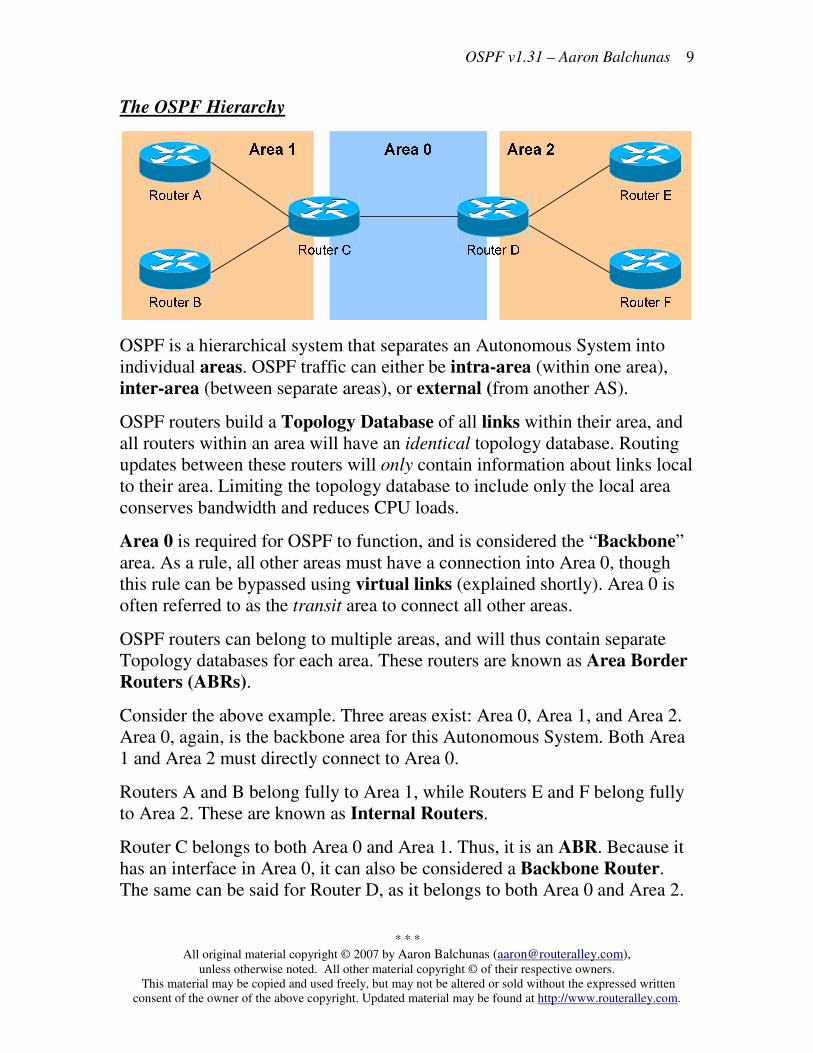
The OSPF Hierarchy
OSPF is a hierarchical system that separates an Autonomous System into
individual areas. OSPF traffic can either be intra-area (within one area),
inter-area (between separate areas), or external (from another AS).
OSPF routers build a Topology Database of all links within their area, and
all routers within an area will have an identical topology database. Routing
updates between these routers will only contain information about links local
to their area. Limiting the topology database to include only the local area
conserves bandwidth and reduces CPU loads.
Area 0 is required for OSPF to function, and is considered the “Backbone”
area. As a rule, all other areas must have a connection into Area 0, though
this rule can be bypassed using virtual links (explained shortly). Area 0 is
often referred to as the transit area to connect all other areas.
OSPF routers can belong to multiple areas, and will thus contain separate
Topology databases for each area. These routers are known as Area Border
Routers (ABRs).
Consider the above example. Three areas exist: Area 0, Area 1, and Area 2.
Area 0, again, is the backbone area for this Autonomous System. Both Area
1 and Area 2 must directly connect to Area 0.
Routers A and B belong fully to Area 1, while Routers E and F belong fully
to Area 2. These are known as Internal Routers.
Router C belongs to both Area 0 and Area 1. Thus, it is an ABR. Because it
has an interface in Area 0, it can also be considered a Backbone Router.
The same can be said for Router D, as it belongs to both Area 0 and Area 2.
OSPF v1.31 – Aaron Balchunas
* * *
All original material copyright © 2007 by Aaron Balchunas ([email protected]), unless otherwise noted. All other material copyright © of their respective owners.
This material may be copied and used freely, but may not be altered or sold without the expressed written
consent of the owner of the above copyright. Updated material may be found at http://www.routeralley.com.
10
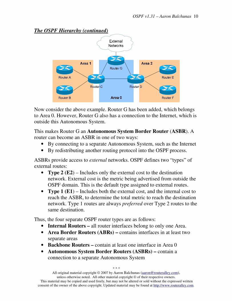
The OSPF Hierarchy (continued)
Now consider the above example. Router G has been added, which belongs
to Area 0. However, Router G also has a connection to the Internet, which is
outside this Autonomous System.
This makes Router G an Autonomous System Border Router (ASBR). A
router can become an ASBR in one of two ways:
• By connecting to a separate Autonomous System, such as the Internet
• By redistributing another routing protocol into the OSPF process.
ASBRs provide access to external networks. OSPF defines two “types” of
external routes:
• Type 2 (E2) – Includes only the external cost to the destination
network. External cost is the metric being advertised from outside the
OSPF domain. This is the default type assigned to external routes.
• Type 1 (E1) – Includes both the external cost, and the internal cost to
reach the ASBR, to determine the total metric to reach the destination
network. Type 1 routes are always preferred over Type 2 routes to the
same destination.
Thus, the four separate OSPF router types are as follows:
• Internal Routers – all router interfaces belong to only one Area.
• Area Border Routers (ABRs) – contains interfaces in at least two
separate areas
• Backbone Routers – contain at least one interface in Area 0
• Autonomous System Border Routers (ASBRs) – contain a
connection to a separate Autonomous System

OSPF v1.31 – Aaron Balchunas
* * *
All original material copyright © 2007 by Aaron Balchunas ([email protected]), unless otherwise noted. All other material copyright © of their respective owners.
This material may be copied and used freely, but may not be altered or sold without the expressed written
consent of the owner of the above copyright. Updated material may be found at http://www.routeralley.com.
11
LSAs and the OSPF Topology Database
OSPF, as a link-state routing protocol, does not rely on routing-by-rumor as
RIP and IGRP do.
Instead, OSPF routers keep track of the status of links within their respective
areas. A link is simply a router interface. From these lists of links and their
respective statuses, the topology database is created. OSPF routers forward
link-state advertisements (LSAs) to ensure the topology database is
consistent on each router within an area.
Several LSA types exist:
• Router LSA (Type 1) – Contains a list of all links local to the router, and
the status and “cost” of those links. Type 1 LSAs are generated by all
routers in OSPF, and are flooded to all other routers within the local area.
• Network LSA (Type 2) – Generated by all Designated Routers in OSPF,
and contains a list of all routers attached to the Designated Router.
• Network Summary LSA (Type 3) – Generated by all ABRs in OSPF,
and contains a list of all destination networks within an area. Type 3
LSAs are sent between areas to allow inter-area communication to occur.
• ASBR Summary LSA (Type 4) – Generated by ABRs in OSPF, and
contains a route to any ASBRs in the OSPF system. Type 4 LSAs are
sent from an ABR into its local area, so that Internal routers know how to
exit the Autonomous System.
• External LSA (Type 5) – Generated by ASBRs in OSPF, and contain
routes to destination networks outside the local Autonomous System.
Type 5 LSAs can also take the form of a default route to all networks
outside the local AS. Type 5 LSAs are flooded to all areas in the OSPF
system.
Multicast OSPF (MOSPF) utilizes a Type 6 LSA, but that goes beyond the
scope of this guide.
Later in this section, Type 7 NSSA External LSAs will be described in
detail.

OSPF v1.31 – Aaron Balchunas
* * *
All original material copyright © 2007 by Aaron Balchunas ([email protected]), unless otherwise noted. All other material copyright © of their respective owners.
This material may be copied and used freely, but may not be altered or sold without the expressed written
consent of the owner of the above copyright. Updated material may be found at http://www.routeralley.com.
12
LSAs and the OSPF Topology Database (continued)
From the above example, the following can be determined:
• Routers A, B, E, and F are Internal Routers.
• Routers C and D are ABRs.
• Router G is an ASBR.
All routers will generate Router (Type 1) LSAs. For example, Router A
will generate a Type 1 LSA that contains the status of links FastEthernet 0/0
and FastEthernet 0/1. This LSA will be flooded to all other routers in Area 1.
Designated Routers will generate Network (Type 2) LSAs. For example, if
Router C was elected the DR for the multi-access network in Area 1, it
would generate a Type 2 LSA containing a list of all routers attached to it.
Area Border Routers (ABRs) will generate Network Summary (Type 3)
LSAs. For example, Router C is an ABR between Area 0 and Area 1. It will
thus send Type 3 LSAs into both areas. Type 3 LSAs sent into Area 0 will
contain a list of networks within Area 1, including costs to reach those
networks. Type 3 LSAs sent into Area 1 will contain a list of networks
within Area 0, and all other areas connected to Area 0. This allows Area 1 to
reach any other area, and all other areas to reach Area 1.
OSPF v1.31 – Aaron Balchunas
* * *
All original material copyright © 2007 by Aaron Balchunas ([email protected]), unless otherwise noted. All other material copyright © of their respective owners.
This material may be copied and used freely, but may not be altered or sold without the expressed written
consent of the owner of the above copyright. Updated material may be found at http://www.routeralley.com.
13
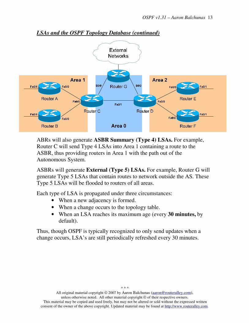
LSAs and the OSPF Topology Database (continued)
ABRs will also generate ASBR Summary (Type 4) LSAs. For example,
Router C will send Type 4 LSAs into Area 1 containing a route to the
ASBR, thus providing routers in Area 1 with the path out of the
Autonomous System.
ASBRs will generate External (Type 5) LSAs. For example, Router G will
generate Type 5 LSAs that contain routes to network outside the AS. These
Type 5 LSAs will be flooded to routers of all areas.
Each type of LSA is propagated under three circumstances:
• When a new adjacency is formed.
• When a change occurs to the topology table.
• When an LSA reaches its maximum age (every 30 minutes, by
default).
Thus, though OSPF is typically recognized to only send updates when a
change occurs, LSA’s are still periodically refreshed every 30 minutes.

OSPF v1.31 – Aaron Balchunas
* * *
All original material copyright © 2007 by Aaron Balchunas ([email protected]), unless otherwise noted. All other material copyright © of their respective owners.
This material may be copied and used freely, but may not be altered or sold without the expressed written
consent of the owner of the above copyright. Updated material may be found at http://www.routeralley.com.
14
The OSPF Metric
OSPF determines the best (or shortest) path to a destination network using a
cost metric, which is based on the bandwidth of interfaces. The total cost of
a route is the sum of all outgoing interface costs. Lowest cost is preferred.
Cisco applies default costs to specific interface types:
Type Cost
Serial (56K) 1785
Serial (64K) 1562
T1 (1.544Mbps) 64
Token Ring (4Mbps) 25
Ethernet (10 Mbps) 10
Token Ring (16 Mbps) 6
Fast Ethernet 1
On Serial interfaces, OSPF will use the configured bandwidth (measured in
Kbps) to determine the cost:
Router(config)# interface s0
Router(config-if)# bandwidth 64
The default cost of an interface can be superseded:
Router(config)# interface e0
Router(config-if)# ip ospf cost 5
Changing the cost of an interface can alter which path OSPF deems the
“shortest,” and thus should be used with great care.
To alter how OSPF calculates its default metrics for interfaces:
Router(config)# router ospf 1
Router(config-router)# ospf auto-cost reference-bandwidth 100
The above ospf auto-cost command has a value of 100 configured, which is
actually the default. This indicates that a 100Mbps link will have a cost of 1
(because 100/100 is 1). All other costs are based off of this. For example, the
cost of 4 Mbps Token Ring is 25 because 100/4 = 25.
OSPF v1.31 – Aaron Balchunas
* * *
All original material copyright © 2007 by Aaron Balchunas ([email protected]), unless otherwise noted. All other material copyright © of their respective owners.
This material may be copied and used freely, but may not be altered or sold without the expressed written
consent of the owner of the above copyright. Updated material may be found at http://www.routeralley.com.
15
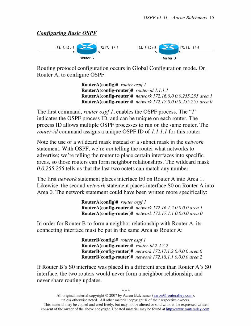
Configuring Basic OSPF
Routing protocol configuration occurs in Global Configuration mode. On
Router A, to configure OSPF:
RouterA(config)# router ospf 1
RouterA(config-router)# router-id 1.1.1.1
RouterA(config-router)# network 172.16.0.0 0.0.255.255 area 1
RouterA(config-router)# network 172.17.0.0 0.0.255.255 area 0
The first command, router ospf 1, enables the OSPF process. The “1”
indicates the OSPF process ID, and can be unique on each router. The
process ID allows multiple OSPF processes to run on the same router. The
router-id command assigns a unique OSPF ID of 1.1.1.1 for this router.
Note the use of a wildcard mask instead of a subnet mask in the network
statement. With OSPF, we’re not telling the router what networks to
advertise; we’re telling the router to place certain interfaces into specific
areas, so those routers can form neighbor relationships. The wildcard mask
0.0.255.255 tells us that the last two octets can match any number.
The first network statement places interface E0 on Router A into Area 1.
Likewise, the second network statement places interface S0 on Router A into
Area 0. The network statement could have been written more specifically:
RouterA(config)# router ospf 1
RouterA(config-router)# network 172.16.1.2 0.0.0.0 area 1
RouterA(config-router)# network 172.17.1.1 0.0.0.0 area 0
In order for Router B to form a neighbor relationship with Router A, its
connecting interface must be put in the same Area as Router A:
RouterB(config)# router ospf 1
RouterA(config-router)# router-id 2.2.2.2
RouterB(config-router)# network 172.17.1.2 0.0.0.0 area 0
RouterB(config-router)# network 172.18.1.1 0.0.0.0 area 2
If Router B’s S0 interface was placed in a different area than Router A’s S0
interface, the two routers would never form a neighbor relationship, and
never share routing updates.

OSPF v1.31 – Aaron Balchunas
* * *
All original material copyright © 2007 by Aaron Balchunas ([email protected]), unless otherwise noted. All other material copyright © of their respective owners.
This material may be copied and used freely, but may not be altered or sold without the expressed written
consent of the owner of the above copyright. Updated material may be found at http://www.routeralley.com.
16
OSPF Passive-Interfaces
It is possible to control which router interfaces will participate in the OSPF
process. Just as with EIGRP and RIP, we can use the passive-interface
command.
However, please note that the passive-interface command works differently
with OSPF than with RIP or IGRP. OSPF will no longer form neighbor
relationships out of a “passive” interface, thus this command prevents
updates from being sent or received out of this interface:
RouterC(config)# router ospf 1
RouterC(config-router)# network 10.4.0.0 0.0.255.255 area 0
RouterC(config-router)# network 10.2.0.0 0.0.255.255 area 0
RouterC(config-router)# passive-interface s0
Router C will not form a neighbor adjacency with Router B.
It is possible to configure all interfaces to be passive using the passive-
interface default command, and then individually use the no passive-
interface command on the interfaces that neighbors should be formed on:
RouterC(config)# router ospf 1
RouterC(config-router)# network 10.4.0.0 0.0.255.255 area 0
RouterC(config-router)# network 10.2.0.0 0.0.255.255 area 0
RouterC(config-router)# passive-interface default
RouterC(config-router)# no passive-interface e0
Always remember, that the passive-interface command will prevent OSPF
(and EIGRP) from forming neighbor relationships out of that interface. No
routing updates are passed in either direction.
OSPF v1.31 – Aaron Balchunas
* * *
All original material copyright © 2007 by Aaron Balchunas ([email protected]), unless otherwise noted. All other material copyright © of their respective owners.
This material may be copied and used freely, but may not be altered or sold without the expressed written
consent of the owner of the above copyright. Updated material may be found at http://www.routeralley.com.
17
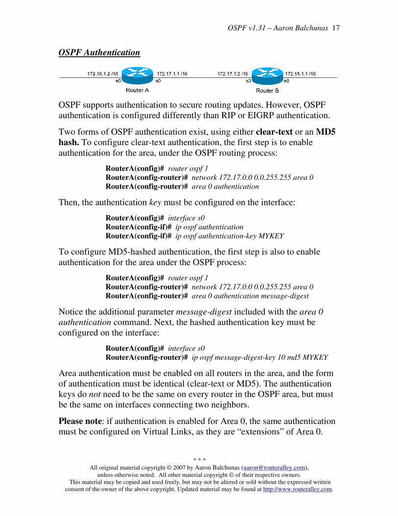
OSPF Authentication
OSPF supports authentication to secure routing updates. However, OSPF
authentication is configured differently than RIP or EIGRP authentication.
Two forms of OSPF authentication exist, using either clear-text or an MD5
hash. To configure clear-text authentication, the first step is to enable
authentication for the area, under the OSPF routing process:
RouterA(config)# router ospf 1
RouterA(config-router)# network 172.17.0.0 0.0.255.255 area 0
RouterA(config-router)# area 0 authentication
Then, the authentication key must be configured on the interface:
RouterA(config)# interface s0
RouterA(config-if)# ip ospf authentication
RouterA(config-if)# ip ospf authentication-key MYKEY
To configure MD5-hashed authentication, the first step is also to enable
authentication for the area under the OSPF process:
RouterA(config)# router ospf 1
RouterA(config-router)# network 172.17.0.0 0.0.255.255 area 0
RouterA(config-router)# area 0 authentication message-digest
Notice the additional parameter message-digest included with the area 0
authentication command. Next, the hashed authentication key must be
configured on the interface:
RouterA(config)# interface s0
RouterA(config-router)# ip ospf message-digest-key 10 md5 MYKEY
Area authentication must be enabled on all routers in the area, and the form
of authentication must be identical (clear-text or MD5). The authentication
keys do not need to be the same on every router in the OSPF area, but must
be the same on interfaces connecting two neighbors.
Please note: if authentication is enabled for Area 0, the same authentication
must be configured on Virtual Links, as they are “extensions” of Area 0.

OSPF v1.31 – Aaron Balchunas
* * *
All original material copyright © 2007 by Aaron Balchunas ([email protected]), unless otherwise noted. All other material copyright © of their respective owners.
This material may be copied and used freely, but may not be altered or sold without the expressed written
consent of the owner of the above copyright. Updated material may be found at http://www.routeralley.com.
18
OSPF Virtual Links
Earlier in this guide, it was stated that all areas must directly connect into
Area 0, as a rule. In the above example, Area 2 has no direct connection to
Area 0, but must transit through Area 1 to reach the backbone area. In
normal OSPF operation, this shouldn’t be possible.
There may be certain circumstances that may prevent an area from directly
connecting into Area 0. Virtual links can be used as a workaround, to
logically connect separated areas to Area 0. In the above example, a virtual
link would essentially create a tunnel from Area 2 to Area 0, using Area 1 a
transit area. One end of the Virtual Link must be connected to Area 0.
Configuration occurs on the Area Border Routers (ABRs) connecting Area
1 to Area 2 (Router B), and Area 1 to Area 0 (Router C). Configuration on
Router B would be as follows:
RouterB(config)# router ospf 1
RouterB(config-router)# router-id 2.2.2.2
RouterB(config-router)# area 1 virtual-link 3.3.3.3
The first command enables the ospf process. The second command manually
sets the router-id for Router B to 2.2.2.2.
The third command actually creates the virtual-link. Notice that it specifies
area 1, which is the transit area. Finally, the command points to the remote
ABR’s Router ID of 3.3.3.3.
Configuration on Router C would be as follows:
RouterC(config)# router ospf 1
RouterC(config-router)# router-id 3.3.3.3
RouterC(config-router)# area 1 virtual-link 2.2.2.2
OSPF v1.31 – Aaron Balchunas
* * *
All original material copyright © 2007 by Aaron Balchunas ([email protected]), unless otherwise noted. All other material copyright © of their respective owners.
This material may be copied and used freely, but may not be altered or sold without the expressed written
consent of the owner of the above copyright. Updated material may be found at http://www.routeralley.com.
19
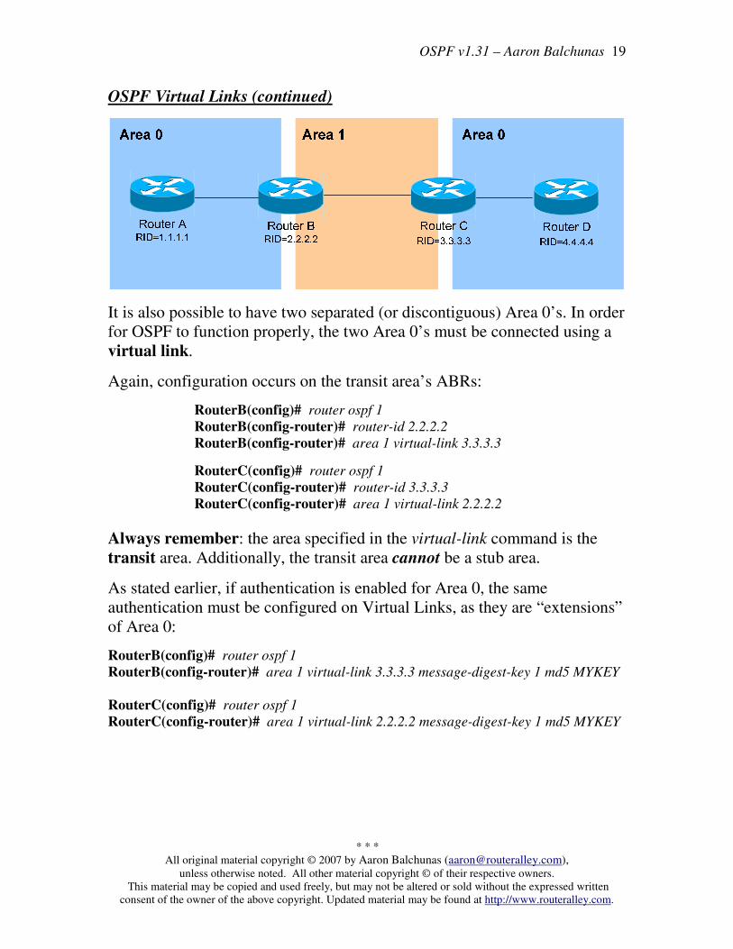
OSPF Virtual Links (continued)
It is also possible to have two separated (or discontiguous) Area 0’s. In order
for OSPF to function properly, the two Area 0’s must be connected using a
virtual link.
Again, configuration occurs on the transit area’s ABRs:
RouterB(config)# router ospf 1
RouterB(config-router)# router-id 2.2.2.2
RouterB(config-router)# area 1 virtual-link 3.3.3.3
RouterC(config)# router ospf 1
RouterC(config-router)# router-id 3.3.3.3
RouterC(config-router)# area 1 virtual-link 2.2.2.2
Always remember: the area specified in the virtual-link command is the
transit area. Additionally, the transit area cannot be a stub area.
As stated earlier, if authentication is enabled for Area 0, the same
authentication must be configured on Virtual Links, as they are “extensions”
of Area 0:
RouterB(config)# router ospf 1
RouterB(config-router)# area 1 virtual-link 3.3.3.3 message-digest-key 1 md5 MYKEY
RouterC(config)# router ospf 1
RouterC(config-router)# area 1 virtual-link 2.2.2.2 message-digest-key 1 md5 MYKEY
OSPF v1.31 – Aaron Balchunas
* * *
All original material copyright © 2007 by Aaron Balchunas ([email protected]), unless otherwise noted. All other material copyright © of their respective owners.
This material may be copied and used freely, but may not be altered or sold without the expressed written
consent of the owner of the above copyright. Updated material may be found at http://www.routeralley.com.
20
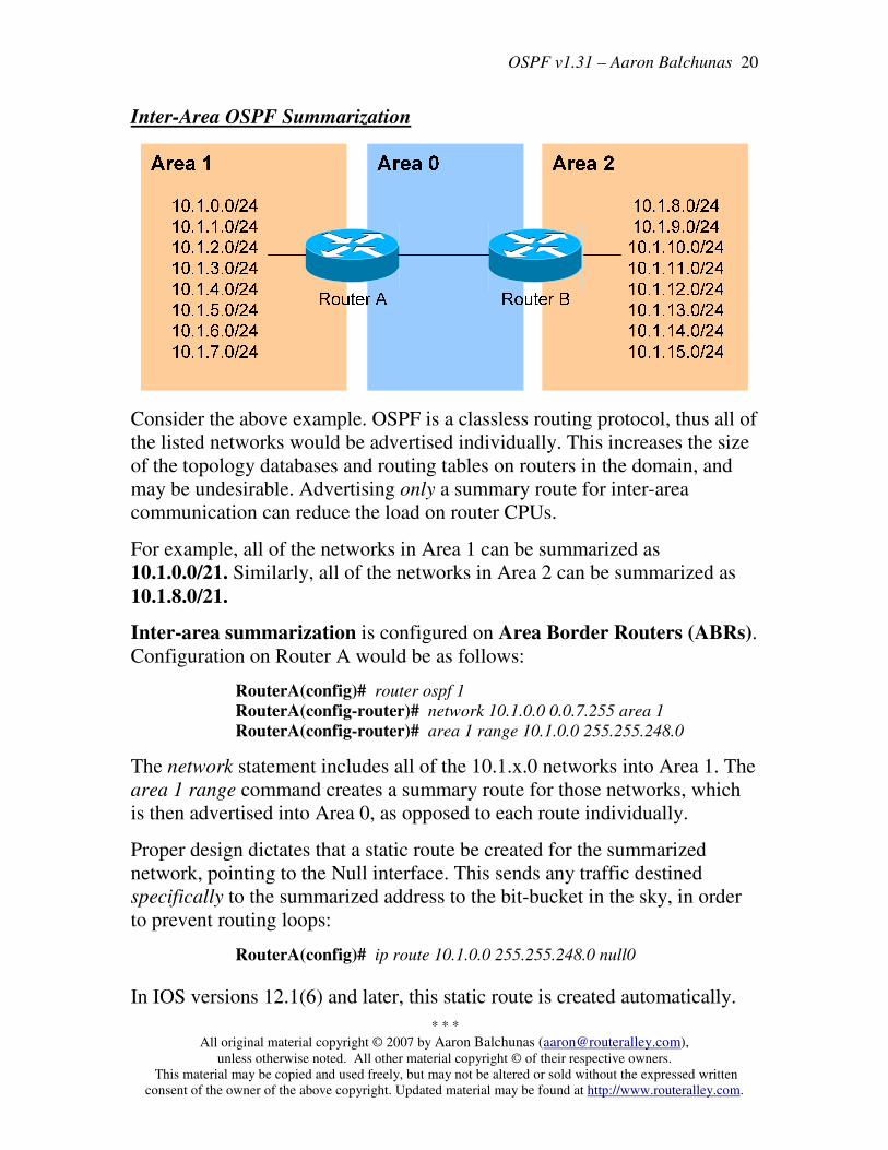
Inter-Area OSPF Summarization
Consider the above example. OSPF is a classless routing protocol, thus all of
the listed networks would be advertised individually. This increases the size
of the topology databases and routing tables on routers in the domain, and
may be undesirable. Advertising only a summary route for inter-area
communication can reduce the load on router CPUs.
For example, all of the networks in Area 1 can be summarized as
10.1.0.0/21. Similarly, all of the networks in Area 2 can be summarized as
10.1.8.0/21.
Inter-area summarization is configured on Area Border Routers (ABRs).
Configuration on Router A would be as follows:
RouterA(config)# router ospf 1
RouterA(config-router)# network 10.1.0.0 0.0.7.255 area 1
RouterA(config-router)# area 1 range 10.1.0.0 255.255.248.0
The network statement includes all of the 10.1.x.0 networks into Area 1. The
area 1 range command creates a summary route for those networks, which
is then advertised into Area 0, as opposed to each route individually.
Proper design dictates that a static route be created for the summarized
network, pointing to the Null interface. This sends any traffic destined
specifically to the summarized address to the bit-bucket in the sky, in order
to prevent routing loops:
RouterA(config)# ip route 10.1.0.0 255.255.248.0 null0
In IOS versions 12.1(6) and later, this static route is created automatically.

OSPF v1.31 – Aaron Balchunas
* * *
All original material copyright © 2007 by Aaron Balchunas ([email protected]), unless otherwise noted. All other material copyright © of their respective owners.
This material may be copied and used freely, but may not be altered or sold without the expressed written
consent of the owner of the above copyright. Updated material may be found at http://www.routeralley.com.
21
External OSPF Summarization
Consider the above example. Router B is an Autonomous System Border
Router (ASBR). It is possible to redistribute the four “external” networks
into the OSPF system. However, a separate route for each network will be
advertised.
Again, this is wasteful. The four external networks can be summarized as
15.0.0.0/14.
External Summarization is configured on ASBRs, and will only
summarize external routes learned by route redistribution. Configuration on
Router B would be as follows:
RouterB(config)# router ospf 1
RouterB(config-router)# summary-address 15.0.0.0 255.252.0.0
This summarized route is now propagated to all routers in every OSPF area.
Summarization can be used to filter certain routes (true route filtering is
covered in a separate guide). To force OSPF to advertise the 15.0.0.0 and
15.1.0.0 networks as a summarized route, but not advertise the 15.2.0.0 and
15.3.0.0 prefixes:
RouterB(config)# router ospf 1
RouterB(config-router)# summary-address 15.0.0.0 255.254.0.0
RouterB(config-router)# summary-address 15.2.0.0 255.255.0.0 not-advertise
RouterB(config-router)# summary-address 15.3.0.0 255.255.0.0 not-advertise
The first summary-address command summarizes the 15.0.0.0/16 and
15.1.0.0/16 networks to 15.0.0.0/15, and advertises the summary as normal
in the OSPF domain. The next two summary-address commands specifically
reference the 15.2.0.0/16 and 15.3.0.0/16 networks, with the not-advertise
parameter. As implied, these networks will not be advertised in OSPF.

OSPF v1.31 – Aaron Balchunas
* * *
All original material copyright © 2007 by Aaron Balchunas ([email protected]), unless otherwise noted. All other material copyright © of their respective owners.
This material may be copied and used freely, but may not be altered or sold without the expressed written
consent of the owner of the above copyright. Updated material may be found at http://www.routeralley.com.
22
OSPF Area Types
In order to control the propagation of LSAs in the OSPF domain, several
area types were developed.
Standard Area – A “normal” OSPF area.
• Routers within a standard area will share Router (Type 1) and
Network (Type 2) LSAs to build their topology tables. Once fully
synchronized, routers within an area will all have identical
topology tables.
• Standard areas will accept Network Summary (Type 3) LSAs,
which contain the routes to reach networks in all other areas.
• Standard areas will accept ASBR Summary (Type 4) and External
(Type 5) LSAs, which contain the route to the ASBR and routes to
external networks, respectively.
Configuration of standard areas is straight forward:
Router(config)# router ospf 1
Router(config-router)# network 10.1.0.0 0.0.7.255 area 1
Stub Area – Prevents external routes from flooding into an area.
• Like Standard areas, Stub area routers will share Type 1 and Type
2 LSAs to build their topology tables.
• Stub areas will also accept Type 3 LSAs to reach other areas.
• Stub areas will not accept Type 4 or Type 5 LSAs, detailing routes
to external networks.
The purpose of Stub areas is to limit the number of LSAs flooded into the
area, to conserve bandwidth and router CPUs. The Stub’s ABR will
automatically inject a default route into the Stub area, so that those routers
can reach the external networks. The ABR will be the next-hop for the
default route.
Configuration of stub areas is relatively simple:
Router(config)# router ospf 1
Router(config-router)# network 10.1.0.0 0.0.7.255 area 1
Router(config-router)# area 1 stub
The area 1 stub command must be configured on all routers in the Stub area.
No ASBRs are allowed in a Stub area.

OSPF v1.31 – Aaron Balchunas
* * *
All original material copyright © 2007 by Aaron Balchunas ([email protected]), unless otherwise noted. All other material copyright © of their respective owners.
This material may be copied and used freely, but may not be altered or sold without the expressed written
consent of the owner of the above copyright. Updated material may be found at http://www.routeralley.com.
23
OSPF Area Types (continued)
Totally Stubby Area – Prevents both inter-area and external routes from
flooding into an area.
• Like Standard and Stub areas, Totally Stubby area routers will
share Type 1 and Type 2 LSAs to build their topology tables.
• Totally Stubby areas will not accept Type 3 LSAs to other areas.
• Totally Stubby areas will also not accept Type 4 or Type 5 LSAs,
detailing routes to external networks.
Again, the purpose of Totally Stubby areas is to limit the number of LSAs
flooded into the area, to conserve bandwidth and router CPUs. The Stub’s
ABR will instead automatically inject a default route into the Totally
Stubby area, so that those routers can reach both inter-area networks and
external networks. The ABR will be the next-hop for the default route.
Configuration of totally stubby areas is relatively simple:
Router(config)# router ospf 1
Router(config-router)# network 10.1.0.0 0.0.7.255 area 1
Router(config-router)# area 1 stub no-summary
The area 1 stub no-summary command is configured only on the ABR of
the Totally Stubby area; other routers within the area are configured with the
area 1 stub command. No ASBRs are allowed in a Totally Stubby area.
In the above example, if we were to configure Area 1 as a Totally Stubby
area, it would not accept any external routes originating from the ASBR
(Router G). It also would not accept any Type 3 LSAs containing route
information about Area 0 and Area 2. Instead, Router C (the ABR) will
inject a default route into Area 1, and all routers within Area 1 will use
Router C as their gateway to all other networks.

OSPF v1.31 – Aaron Balchunas
* * *
All original material copyright © 2007 by Aaron Balchunas ([email protected]), unless otherwise noted. All other material copyright © of their respective owners.
This material may be copied and used freely, but may not be altered or sold without the expressed written
consent of the owner of the above copyright. Updated material may be found at http://www.routeralley.com.
24
OSPF Area Types (continued)
Router A
Router B
Router C
Router E
Router F
Router D
Area 0
Area 2Area 1
Router G
External
Networks
More External
Networks
Not So Stubby Area (NSSA) – Similar to a Stub area; prevents external
routes from flooding into an area, unless those external routes originated
from an ASBR within the NSSA area.
• Like Standard and Stub areas, NSSA area routers will share Type 1
and Type 2 LSAs to build their topology tables.
• NSSA areas will also accept Network Summary (Type 3) LSAs,
which contain the routes to reach networks in all other areas.
• NSSA areas will not accept Type 4 or Type 5 LSAs, detailing
routes to external networks.
• If an ASBR exists within the NSSA area, that ASBR will generate
Type 7 LSAs.
Again, NSSA areas are almost identical to Stub areas. If Area 1 was
configured as an NSSA, it would not accept any external routes originating
from Router G (an ASBR outside Area 1).
However, Area 1 also has an ASBR within the area (Router A). Those
external routes will be flooded into Area 1 as Type 7 LSAs. These external
routes will not be forwarded to other areas as Type 7 LSAs; instead, they
will be converted into Type 5 LSAs by Area 1’s ABR (Router C).
Configuration of NSSA areas is relatively simple:
Router(config)# router ospf 1
Router(config-router)# network 10.1.0.0 0.0.7.255 area 1
Router(config-router)# area 1 nssa
The area 1 nssa command must be applied to all routers in the NSSA area.

OSPF v1.31 – Aaron Balchunas
* * *
All original material copyright © 2007 by Aaron Balchunas ([email protected]), unless otherwise noted. All other material copyright © of their respective owners.
This material may be copied and used freely, but may not be altered or sold without the expressed written
consent of the owner of the above copyright. Updated material may be found at http://www.routeralley.com.
25
OSPF Area Types (continued)
Router A
Router B
Router C
Router E
Router F
Router D
Area 0
Area 2Area 1
Router G
External
Networks
More External
Networks
Totally Not So Stubby Area (TNSSA) – Similar to a Totally Stubby area;
prevents both inter-area and external routes from flooding into an area,
unless those external routes originated from an ASBR within the NSSA area.
• Like Standard and Stub areas, TNSSA area routers will share Type
1 and Type 2 LSAs to build their topology tables.
• TNSSA areas will not accept Type 3 LSAs to other areas.
• TNSSA areas will not accept Type 4 or Type 5 LSAs, detailing
routes to external networks.
• If an ASBR exists within the TNSSA area, that ASBR will
generate Type 7 LSAs.
With the exception of not accepting inter-area routes, TNSSA areas are
identical in function to NSSA areas.
Configuration of TNSSA areas is relatively simple:
Router(config)# router ospf 1
Router(config-router)# network 10.1.0.0 0.0.7.255 area 1
Router(config-router)# area 1 nssa no-summary
The area 1 nssa no-summary command is configured only on the ABR of
the TNSSA area; other routers within the area are configured with the area 1
nssa command.

OSPF v1.31 – Aaron Balchunas
* * *
All original material copyright © 2007 by Aaron Balchunas ([email protected]), unless otherwise noted. All other material copyright © of their respective owners.
This material may be copied and used freely, but may not be altered or sold without the expressed written
consent of the owner of the above copyright. Updated material may be found at http://www.routeralley.com.
26
OSPF and Default Routes
We have learned about four types of OSPF areas:
• Standard areas
• Stub areas
• Totally Stubby areas
• Not So Stubby areas (NSSA)
The ABRs and ASBRs of Standard areas do not automatically generate (or
inject) default routes into the area. Consider the following example:
Router A Router C
Area 0Area 1
External
Networks
Router B
Assume that Area 1 is configured as a Standard area. Router C will forward
Type 3 LSAs from all other areas into Area 1, allowing Router A and Router
B to reach inter-area networks.
Notice also that Router A is an ASBR, connecting to an external
Autonomous System. Thus, Router A will generate Type 5 LSAs, detailing
the routes to these external networks.
To additionally force Router A to generate a default route (indicating itself
as the next hop) for the external networks, and inject this into Area 1. This
default route will be advertised as a Type 5 LSA to all other areas:
RouterA(config)# router ospf 1
RouterA(config-router)# default-information originate
Router A must have a default route in its routing table in order for the above
command to function. Router A’s default route would point to some
upstream router in the external Autonomous System.
If a default route does not exist in its routing table, Router A can still be
forced to advertise a default route using the always parameter:
RouterA(config)# router ospf 1
RouterA(config-router)# default-information originate always

OSPF v1.31 – Aaron Balchunas
* * *
All original material copyright © 2007 by Aaron Balchunas ([email protected]), unless otherwise noted. All other material copyright © of their respective owners.
This material may be copied and used freely, but may not be altered or sold without the expressed written
consent of the owner of the above copyright. Updated material may be found at http://www.routeralley.com.
27
OSPF and Default Routes (continued)
The ABRs of Stub and Totally Stubby areas automatically generate (and
inject) a default route (0.0.0.0/0) into the area. Routers in Stub areas use
this default route to reach external networks, while routers in Totally Stubby
areas use the default route to reach both inter-area and external networks.
To control the “cost” metric of the default route in Stub or Totally Stubby
areas (configured on the ABR):
Router(config)# router ospf 1
Router(config-router)# area 1 stub
Router(config-router)# area 1 default-cost 10
The ABRs of NSSA areas must be manually configured to generate (and
inject) a default route into the area:
Router(config)# router ospf 1
Router(config-router)# area 1 nssa default-information-originate
Additionally, the ASBR of an NSSA area can generate and inject a default
route. This default route will be advertised as a Type 7 LSA, as Type 5
LSA’s are not allowed in NSSAs. The command is no different than
injecting a default route from an NSSA ABR:
Router(config)# router ospf 1
Router(config-router)# area 1 nssa default-information-originate
Reference: (http://www.cisco.com/en/US/tech/tk365/technologies_tech_note09186a0080094a74.shtml)

OSPF v1.31 – Aaron Balchunas
* * *
All original material copyright © 2007 by Aaron Balchunas ([email protected]), unless otherwise noted. All other material copyright © of their respective owners.
This material may be copied and used freely, but may not be altered or sold without the expressed written
consent of the owner of the above copyright. Updated material may be found at http://www.routeralley.com.
28
OSPF SPF Timers
To adjust the SPF timers in OSPF:
Router(config)# router ospf 1
Router(config-router)# timers spf 10 15
The timers spf command includes two parameters, measured in seconds. The
first (10) indicates the SPF-Delay, or how long the OSPF should wait after
receiving a topology change to recalculate the shortest path. The second (15)
indicates the SPF-Holdtime, or how long OSPF should wait in between
separate SPF calculations.
The timers spf command has actually become deprecated. It has been
replaced with:
Router(config)# router ospf 1
Router(config-router)# timers throttle spf 5 10000 80000
The timers throttle spf command includes three parameters, measure in
milliseconds. The first (5) indicates how long OSPF should wait after
receiving a topology change to recalculate the shortest path. The second
(10000) indicates the hold-down time, or how long OSPF should wait in
between separate SPF calculations. If OSPF receives another topology
change during the hold-time interval, it will continue to double the hold-time
interval until it reaches the maximum hold-time (80000).
The purpose of the both SPF timer commands is to prevent OSPF from
constantly converging, if the network links are “flapping.” The timers spf
and timers throttle spf commands cannot be used together.
OSPF v1.31 – Aaron Balchunas
* * *
All original material copyright © 2007 by Aaron Balchunas ([email protected]), unless otherwise noted. All other material copyright © of their respective owners.
This material may be copied and used freely, but may not be altered or sold without the expressed written
consent of the owner of the above copyright. Updated material may be found at http://www.routeralley.com.
29
Advanced OSPF Configuration
To force the OSPF process to ignore OSPF Multicast (Type 6) LSAs:
Router(config)# router ospf 1
Router(config-router)# ignore lsa mospf
To force an interface to filter all outgoing OSPF LSA’s:
Router(config)# interface e0
Router(config-if)# ip ospf database-filter all out
Loopback interfaces are treated differently than other interfaces, when
advertised in OSPF. OSPF will advertise a loopback interface as a specific
“host” route (with a mask of /32 or 255.255.255.255). To force OSPF to
advertise a loopback interface with its proper subnet mask:
Router(config)# interface loopback0
Router(config-if)# ip address 10.50.5.1 255.255.255.0
Router(config-if)# ip ospf network point-to-point
OSPF v1.31 – Aaron Balchunas
* * *
All original material copyright © 2007 by Aaron Balchunas ([email protected]), unless otherwise noted. All other material copyright © of their respective owners.
This material may be copied and used freely, but may not be altered or sold without the expressed written
consent of the owner of the above copyright. Updated material may be found at http://www.routeralley.com.
30
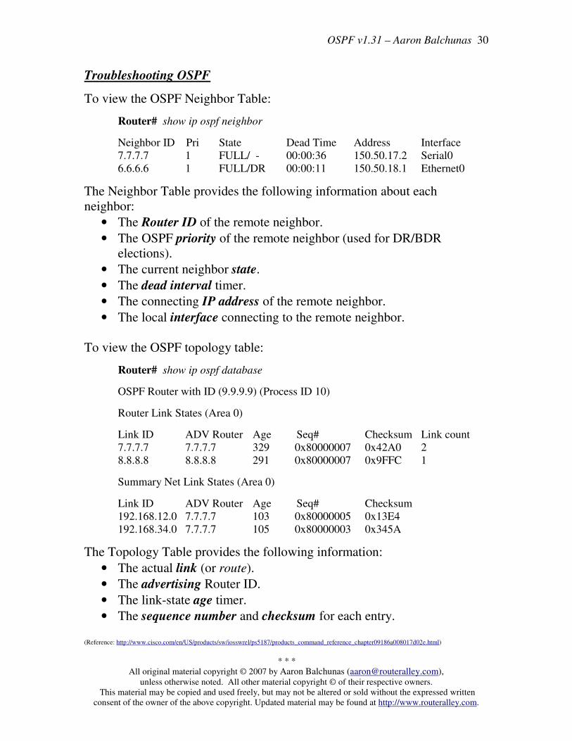
Troubleshooting OSPF
To view the OSPF Neighbor Table:
Router# show ip ospf neighbor
Neighbor ID Pri State Dead Time Address Interface
7.7.7.7 1 FULL/ - 00:00:36 150.50.17.2 Serial0
6.6.6.6 1 FULL/DR 00:00:11 150.50.18.1 Ethernet0
The Neighbor Table provides the following information about each
neighbor:
• The Router ID of the remote neighbor.
• The OSPF priority of the remote neighbor (used for DR/BDR
elections).
• The current neighbor state.
• The dead interval timer.
• The connecting IP address of the remote neighbor.
• The local interface connecting to the remote neighbor.
To view the OSPF topology table:
Router# show ip ospf database
OSPF Router with ID (9.9.9.9) (Process ID 10)
Router Link States (Area 0)
Link ID ADV Router Age Seq# Checksum Link count
7.7.7.7 7.7.7.7 329 0x80000007 0x42A0 2
8.8.8.8 8.8.8.8 291 0x80000007 0x9FFC 1
Summary Net Link States (Area 0)
Link ID ADV Router Age Seq# Checksum
192.168.12.0 7.7.7.7 103 0x80000005 0x13E4
192.168.34.0 7.7.7.7 105 0x80000003 0x345A
The Topology Table provides the following information:
• The actual link (or route).
• The advertising Router ID.
• The link-state age timer.
• The sequence number and checksum for each entry.
(Reference: http://www.cisco.com/en/US/products/sw/iosswrel/ps5187/products_command_reference_chapter09186a008017d02e.html)

OSPF v1.31 – Aaron Balchunas
* * *
All original material copyright © 2007 by Aaron Balchunas ([email protected]), unless otherwise noted. All other material copyright © of their respective owners.
This material may be copied and used freely, but may not be altered or sold without the expressed written
consent of the owner of the above copyright. Updated material may be found at http://www.routeralley.com.
31
Troubleshooting OSPF (continued)
To view the specific information about an OSPF process:
Router# show ip ospf 1
Routing Process "ospf 1" with ID 9.9.9.9
Supports only single TOS(TOS0) routes
Supports opaque LSA
SPF schedule delay 5 secs, Hold time between two SPFs 10 secs
Minimum LSA interval 5 secs. Minimum LSA arrival 1 secs
Number of external LSA 0. Checksum Sum 0x0
Number of opaque AS LSA 0. Checksum Sum 0x0
Number of DCbitless external and opaque AS LSA 0
Number of DoNotAge external and opaque AS LSA 0
Number of areas in this router is 1. 1 normal 0 stub 0 nssa
External flood list length 0
Area BACKBONE(0)
Number of interfaces in this area is 1
Area has no authentication
SPF algorithm executed 3 times
Area ranges are
Number of LSA 2. Checksum Sum 0xDDEC
Number of opaque link LSA 0. Checksum Sum 0x0
Number of DCbitless LSA 0
Number of indication LSA 0
Number of DoNotAge LSA 0
Flood list length 0
The show ip ospf command provides the following information:
• The local Router ID.
• SPF Scheduling information, and various SPF timers.
• The number of interfaces in specific areas, including the type of area.
• The link-state age timer.
• The sequence number and checksum for each entry.

OSPF v1.31 – Aaron Balchunas
* * *
All original material copyright © 2007 by Aaron Balchunas ([email protected]), unless otherwise noted. All other material copyright © of their respective owners.
This material may be copied and used freely, but may not be altered or sold without the expressed written
consent of the owner of the above copyright. Updated material may be found at http://www.routeralley.com.
32
Troubleshooting OSPF (continued)
To view OSPF-specific information on an interface:
Router# show ip ospf interface s0
Serial0 is up, line protocol is up
Internet Address 192.168.79.2/24, Area 0
Process ID 10, Router ID 9.9.9.9, Network Type POINT_TO_POINT, Cost: 64
Transmit Delay is 1 sec, State POINT_TO_POINT,
Timer intervals configured, Hello 10, Dead 40, Wait 40, Retransmit 5
Hello due in 00:00:04
Index 1/1, flood queue length 0
Next 0x0(0)/0x0(0)
Last flood scan length is 1, maximum is 1
Last flood scan time is 0 msec, maximum is 0 msec
Neighbor Count is 1, Adjacent neighbor count is 1
Adjacent with neighbor 7.7.7.7
Suppress hello for 0 neighbor(s)
The show ip ospf interface command provides the following information:
• The local Router ID.
• The interface network type.
• The OSPF cost for the interface.
• The interface Hello and Dead timers.
• A list of neighbor adjacencies.
To view routing protocol specific information for OSPF:
Router# show ip protocols
Routing Protocol is “ospf 10"
Invalid after 0 seconds, hold down 0, flushed after 0
Outgoing update filter list for all interfaces is
Incoming update filter list for all interfaces is
Routing for Networks:
192.168.79.0 0.0.0.255 area 0
192.168.109.0 0.0.0.255 area 0
Routing Information Sources:
Gateway Distance Last Update
7.7.7.7 110 00:01:05
Distance: (default is 110)
The show ip protocols command provides the following information:
• Locally originated networks that are being advertised.
• Neighboring sources for routing information
• The administrative distance of neighboring sources.

OSPF v1.31 – Aaron Balchunas
* * *
All original material copyright © 2007 by Aaron Balchunas ([email protected]), unless otherwise noted. All other material copyright © of their respective owners.
This material may be copied and used freely, but may not be altered or sold without the expressed written
consent of the owner of the above copyright. Updated material may be found at http://www.routeralley.com.
33
Troubleshooting OSPF (continued)
To reset an OSPF process, including neighbor adjacencies:
Router# clear ip ospf process
To display information about OSPF virtual-links:
Router# show ip ospf virtual-links
To display routes to both ABRs and ASBRs:
Router# show ip ospf border-routers
To debug OSPF in realtime:
Router# debug ip ospf adj
Router# debug ip ospf events
Router# debug ip ospf hello