Embed Size (px)
Citation preview

Mr. Juan M. CarbonellMr. Juan M. CarbonellAFRL/AAS, Project ManagerAFRL/AAS, Project Manager
Mr. Mikel J. HarrisMr. Mikel J. HarrisLockheed Martin, Engineering Spec. Sr.Lockheed Martin, Engineering Spec. Sr.
Open Systems Architecture forLegacy Aircraft (OSALA)
Open Systems Project Engineering Conference (OSPEC)FY 98 Status Review
29 April - 1 May 1998

REPORT DOCUMENTATION PAGE Form Approved OMB No.0704-0188
Public reporting burder for this collection of information is estibated to average 1 hour per response, including the time for reviewing instructions, searching existing data sources, gathering and maintaining the data needed, and completingand reviewing this collection of information. Send comments regarding this burden estimate or any other aspect of this collection of information, including suggestions for reducing this burder to Department of Defense, WashingtonHeadquarters Services, Directorate for Information Operations and Reports (0704-0188), 1215 Jefferson Davis Highway, Suite 1204, Arlington, VA 22202-4302. Respondents should be aware that notwithstanding any other provision oflaw, no person shall be subject to any penalty for failing to comply with a collection of information if it does not display a currently valid OMB control number. PLEASE DO NOT RETURN YOUR FORM TO THE ABOVE ADDRESS.
1. REPORT DATE (DD-MM-YYYY)29-04-1998
2. REPORT TYPEBriefing
3. DATES COVERED (FROM - TO)29-04-1998 to 01-05-1998
4. TITLE AND SUBTITLEOpen Systems Architecture for Legacy Aircraft (OSALA)Open Systems Project Engineering Conference (OSPEC) FY 98 Status ReviewUnclassified
5a. CONTRACT NUMBER5b. GRANT NUMBER5c. PROGRAM ELEMENT NUMBER
6. AUTHOR(S)Carbonell, Juan M. ;Harris, Mikel J. ;
5d. PROJECT NUMBER5e. TASK NUMBER5f. WORK UNIT NUMBER
7. PERFORMING ORGANIZATION NAME AND ADDRESSAFRL/AASxxxxxxxxxx, xxxxxxx
8. PERFORMING ORGANIZATION REPORTNUMBER
9. SPONSORING/MONITORING AGENCY NAME AND ADDRESSOpen Systems Joint Task Force (OSJTF)1931 Jefferson Davis HighwayCrystal Mall 3, Suite 104Arlington, VA22202
10. SPONSOR/MONITOR'S ACRONYM(S)11. SPONSOR/MONITOR'S REPORTNUMBER(S)
12. DISTRIBUTION/AVAILABILITY STATEMENTAPUBLIC RELEASE,13. SUPPLEMENTARY NOTES14. ABSTRACTSee Report.15. SUBJECT TERMS16. SECURITY CLASSIFICATION OF: 17. LIMITATION
OF ABSTRACTPublic Release
18.NUMBEROF PAGES43
19. NAME OF RESPONSIBLE PERSONhttp://www.acq.osd.mil/osjtf/library/library_alpha.html,(blank)[email protected]
a. REPORTUnclassified
b. ABSTRACTUnclassified
c. THIS PAGEUnclassified
19b. TELEPHONE NUMBERInternational Area CodeArea Code Telephone Number703767-9007DSN427-9007
Standard Form 298 (Rev. 8-98)Prescribed by ANSI Std Z39.18

OSALA Program Overview
Studies• CRAD• Legacy Aircraft• IR&D LMTAS
Industry• Standards
• Open System Standards(Networks & Wireless)
Spec
FinalReport
OS/JTF
ArchBuildingCodes
OpenSystemStudy
NetworkPerformance
Wright Labs
Studies
SystemPerformance
User• Fighter Plans• Needs• Systems
Studies• Joint Strike Fighter• Fiber Optics• Integ. Sensors• JTA v2.0
Definition Task
Proof-of-ConceptEvaluation Task
Point DesignBenchmark• Benefits• Cost Benefits• Commercial Mix• Common
Hardware
Studies and Analysis• Strategies• Open System Candidates• Cost Effectiveness
Assessment• OSA Approach• Metrics• Software Reuse• Hardware• Networks Metrics
Cost Goals
Commonality• Survey
Transport Support• Legacy Systems
A B C
A D
Based on Available Funding
F-16 Baseline

Program Schedule
TASKS
OSALA Program Schedule
CY
Definition • OSA Studies and Analysis • OSA Assessment • OSA Legacy Weapon System Commonality • OSA Point Design BenchmarkProof-of-Concept Evaluation
Reviews and MeetingsAligned to LCICTILA Program ScheduleStatus Reports and Deliverables • Project Planning Chart Revision • Funds & Man-Hour Expenditure Report • CFSR • Status Report • Contractor's Billing Voucher • Final Technical Report
98
TIMPMR
Kickoff Review
17 18 195 6 7 8 9 10 11 12 13 14 15 161 2 3 4
PMR
Final Review
TIM Final Review
97 99Months

Project Organization
Lockheed Martin Tactical Aircraft Systems
Project TeamProject Team Lead
Mr. Mikel J. Harris
Lockheed Martin TeamJon Preston (Software Systems)Tony Schiavone (Architecture and Hardware)Michael DelPrincipe (Embedded Systems)
USAF Program ManagerAFRL
Mr. Juan M. CarbonellOS/JTF Program
Ltc. Glen T. Logan
DirectorSoftware
R. K. Moore
Vice PresidentProduct Engineering
W.B. Anderson

OSALA Progress Summary
• Completed Assessment of Open System Standards
• Completed Analysis of F-16 Avionics Open SystemInsertion Opportunities
• Initiated Wireless Ethernet Studies and Analysis
• OSALA Demonstration: Enhanced DiagnosticsSoftware Integration Started Under Internal IR&D
• Benefits Analysis Task for Open System Standardsto be Concurrent with F-16 RMS/LCC Analysis

Technical Progress Summary
• Roadmaps - Complete• Technology Plans & Roadmaps - Complete• System Baseline Planning Document - Complete• Network Testing - Complete• Wiring Study - Complete• System Requirements Review - Sep. 11,‘97• F-16 HSDB Insertion Team - Review, 13 Nov. 1997• Packaging/Enclosure Studies - Complete• Program Management Review No. 2 - 7 Jan. 1998• Technical Interchange Meeting - 24 February 1998• F-16 Production Planning and Transition - Complete

Technical Activity Forecast
• Program Technical Report Documentation• Briefing to F-16 SPO - May 1998
Coordination With F-16 Production Planning...• Insertion of Open System COTS-based Solutions Into
Aircraft Avionics• ATM Modeling Tasks• RMS/LCC Benefits Analysis

Program Meetings and Reviews
LocationProgram Reviews DateOct 96 - Dec 99
Kickoff Meeting October 96 Dayton, OHProgram Management Review (PMR) February 97 VTCTechnical Interchange Meeting (TIM) April 97 Ft. Worth, TXSystem Requirements Review (SRR) September 97 Ft. Worth, TXOSALA Kickoff October 97 Ft. Worth, TXPMR No. 2 January 98 VTCTIM No. 2 February 98 WashingtonSystem Design Review (SDR) May 98 Ft. Worth, TXand Lab DemonstrationPMR No. 3 June 98 VTCTIM No. 3 September 98 VTCOSALA Final Review & Demo. December 98 Ft. Worth, TX* VTC - Video Teleconference

F-16 Network Study Completed
l Purpose4 Determine What Is the “Best” High Speed
Bus/Network for the F-16
lWorking Constraint4 High Speed Network Is to Go On a “36 Month”
Airplane With January 1998 Go-Ahead
4 Production Incorporation, Retrofit a Consideration( Harnesses Will Be Modified
4 Commercial Build and Procurement

l Generated List of Evaluation Criteria– 29 Criteria Identified
– 9 used for Down Select
l Developed Reference and Achievable Near-TermArchitectures
l Estimated Throughput Required of High SpeedNetwork by Each Architecture
l Down Selected to 2 Candidates– Asynchronous Transfer Mode (ATM)
– Fibre Channel
F-16 Study Summary

Virtually-Integrated Avionics Architecture
Dynamic Real-Time Scheduling
Commercial Packaging
Open Architecture
1995 20001995 2000
First Generation
IntegratedAvionics
• COTS Multiple LRUReplacement
• POSIX CompliantMultitasking RTOS
• MultiprocessingExtensions
• High-BandwidthConnection Bus(PCI)
• COTS, Fully Virtual, AvionicsPlatform
• POSIX Compliant, MultitaskingRTOS
• Distributed Parallel ProcessingExtensions
• High-Bandwidth ConnectionNetwork
• Multiple Language Support (Ada,C, C++)
• Single LRUReplacement
• POSIX CompliantMultitasking RTOS
• Low-BandwidthConnection Bus (VME)
VHDL
OSA
Algorithmsand
Methodology
SecondGeneration
HW/SW Co-Design
MultiprocessingOS ExtensionsBased on RTMTechnology- Ada- POSIX- Commercial RTOS
DistributedParallelProcessingOSExtensions
ThirdGeneration
High-LevelDesign
Language(HDL)

Typical Drawing of the F-16 Architecture
AirData
OtherSystems
Weapons Interface
Mil-Std-1553/B
Heads-UpDisplay
MultifunctionDisplays
Fire ControlComputer
StoresManagement
Mil-Std-1553/B
Radar
InertialUnit

COTS Technologies Can BeUsed To Produce A Low-Cost
Open System Architecture
Integrated Maintenance, Manufacturing, and Support
Weapon Interface
1760A
ISS
Commercial Network
CommercialCore Processing
CommercialBulk
Memory
Commercial DisplaysUART
Advanced Cockpit (HOTAS)
IEO
COTS Technologies Currently Apply
Near-Term Candidates
Digital Signal
Processing
Digital VMS and Flight Control
Processing
Weapons

F-16 Bandwidth Requirements
CategoryRequired Bit Rate
Mbits/Sec
Quantity in Reference
Arch
Total Bit Rate
Required
Quantity in Near Term
System
Total Bit Rate
Required
Basic F-16 5 1 5 0.2 1Download Picture to JASSM 7.4 1 7.4Change Map Scale 7.4 1 7.4 1 7.4Real-Time Video to Displays 45.3 6 271.8Air-to-Air Radar Improvements 0.09 1 0.09 1 0.09
ESM Sensor 0.5 1 0.5Imaging Sensor (FLIR/SAR/GM) 45.3 3 135.9 3 135.9Air Vehicle Systems 1 1 1Data Link 0.5 1 0.5 1 0.5Helmet Mounted Display 0.2 2 0.4 1 0.2
Cockpit I/O 0.25 1 0.25Video Recording (n R/T Videos) 45.3 7 317.1
747 Mb/sec
F-16 Bandwidth Requirements…CY2000
145 Mb/sec

Mission Requirements IndicateA Need for Increased Network Bandwidth
Future Off-Board Bandwidth Requirements for a Typical Fighter Mission
100
1,000
10,000
100,000
1,000,000
(Minutes)Mission Duration (Defensive Counter Air)
Eff
ecti
ve B
it R
ate
(Bit
s/S
ec, L
og
Sca
le)
0 154
Network Topology
q Point-to-point or Mesh q BusTTT
TTT
q Loop
T
T
T
T
T
T
T
T
q SwitchedT T
T T
T
T
SwitchT T
T T
T

Increasing Network BandwidthIs A Key Enabling Technology
A MUX Problem:• Bandwidth Limited• Linear Growth in Buses• Exponential Growth in Memory and
Throughput• Limited by Physical Wiring• Software Cost Prohibitive• Multiple Unique Networks
Alternative:• Mine Existing Wiring Bandwidth• Insert Commercial Network• Migrate Modified LRUs from 1553B
to COTS Network Open Systems Architecture
• Define Process for COTS Insertioninto Legacy LRUs
• Incrementally Upgrade SW/HW• Single Common High Speed Net.
B MUXC MUX
N MUX
One 1553B
CommercialSwitch Digital Video,
Voice, Data
Digital Data
SubsystemA
SubsystemA
SubsystemB
Existing
Future
A ”Cray-in-the-Box” Is No Good Unless The Data Can Be Moved Out
SubsystemBAnalog
Video
LRU Line Replaceable UnitCOTS Commercial Off-the-ShelfSW/HW Software/Hardware

Technology Comparison
WDM
ATM
FC
FW
GbEth
1553B
Cos
t Ris
k(L
ow, M
ed, H
igh)
Protocol / Benchmark Metrics
RTO
S S
oftw
are
(Yes
/No)
Eff
ectiv
e B
andw
idth
(bits
/sec
)P
redi
ctab
ility
(Yes
/No)
Topo
logy
Typ
e
Pro
duci
ble
(Yes
/No)
Med
ia T
ype
(Fib
er, C
oax,
STP
)
Mat
urity
of
Sta
ndar
d(U
sed
1, N
ot U
sed
3)
Ava
ilabi
lity
(Yes
/No)
Most Likely ProtocolWave Division Multiplex
(IRAD)
Mai
ntai
nabl
e(Y
es/N
o)
F-16Aircraft
Mea
sure
s
No
Yes
Yes
Yes
Yes
Yes
3
1
1
2
2
1
FO
ALL
ALL
STP+2
All
Coax,STP
Yes
Yes
Yes
Yes
No
Yes
Bus+
SW
Loop
Chain
SW
Bus
High
Med
Med
Med
High
Low
Yes
Yes
Yes
Yes
No
Yes
No
Yes
Yes
No
No
Yes
No
Yes
Yes
No
No
Yes
FO>10 G
FO >10GCu 60M
FO 800MCu 30M
Cu 200M4.5m limit
4+2pwr
FO 300MCu 20M
Cu800M
Asynchronous Transfer ModeOC-3c, 155Mbps (STS-3c)
Fibre Channel1G FO Loop, STP CDDI
Gigabit EthernetFO 1G or STP Fast Ethernet
Firewire (IEEE 1394-200MB/s)
Mil-Std-1553/B

Assessment
l Fibre Channel Is a Fairly New Standard and Its PersistenceIs Unknown– Currently, Switches Are Not Available for Fibre Channel
– Software Extensions Required for Real-Time Operations
l ATM Is Firmly Entrenched in the TelecommunicationsIndustry– Provides Support and a Growth Path
l ATM Demonstrated on Existing 1553 Cable– Provides Retrofit Opportunities to Existing F-16s
– Only Minimum Group A & B Changes Needed
A Switched ATM Network Is the Baseline for Near-Term F-16 Programs

Production F-16
B2584223
R Fwd Mux Matrix
L Fwd Mux Matrix
R Console Mux Matrix
~
L Console Mux Matrix
MissionComputer
ATMSW 2
ATMSW 1
Radar
Displays
DATACartridge

Proposed F-16 Weapons Interface
ATMSwitch
SubsystemA
SubsystemB
ATMSwitch
StoreStation
SubsystemC
Integ.ECM
Subsystem
• Optical Fiber Added to All Store Stations• Termination at Switch Location• Network Terminals Added to Subsystems in Future Modifications
…Switch to be Located in Mux Matrix Assemblies
StoreStation
StoreStation
StoreStation
StoreStation
StoreStation
StoreStation
StoreStation
StoreStation
StoreStation

Typical Block 30 MUX MatrixAssembly With MIL-STD-1553 Termination

Existing Multiplex Assembly Enclosure
Chassis: 8.2" x 8.1" x 3.0"
Equipment DescriptionDiscrete Signal and Power Interface Switching Network
Functions/Features• Mother Boards – 8 and 14 Layer • 2 Relay Daughter Cards – 6 Relays Per Card • 2 MUX Daughter Cards MIL-STD-1553 Studs for 4 Buses, 8 RTs • Components – 16 Transformers – 33 Resistors – 4 Tranzorbs • Interconnections (J-Box) • Through Hole Technology PCBs

Existing Coupler ModulesAre In Use In Legacy Aircraft
Chassis: 2.5" x 0.8" x 3.0"
Enclosure Provides ImpedanceMatching and Fault Isolation forthe MIL-STD-1553 Data Bus, CanBe Housing for Network Switch
Equipment Description
• High Voltage Protection for Media • Thermoplastic Chassis • Through-Hole Technology
Printed Circuit Board
Functions/Features

Existing Mil-Std-1553/B Wiring Can Be Used to Increase Network Bandwidth
Existing 1553 Network
LegacyLRU 1
LegacyLRU 2
Dual - RedundantMIL-STD-1553/B
over STP at 1Mb/s
Commercial Network
Existing Wiring
Shielded TwistedPairs (STPs)
MUX MatrixAssembly No. 1
Existing 1553/B
Network Card
System 1Upgrade
1553B Cards
Network Card
System 2ProcessorUpgrade
1553B Cards
PowerPower
(STS-3c, 155 Mb/s)
MUX MatrixAssembly No. 2
ATMSwitch
ATMSwitch

Display-MUX
Radar
StoresManagement
MultifunctionDisplays
Head-UpDisplay
Forward DisplayMUX Matrix
2 PAIRS OF 1553/BOR
4 WIRES
Aft DisplayMUX Matrix

Display-MUX AFT Assembly
Aft DisplayMUX Matrix
FireControl
Computer
EWProvisions
ForwardDisplay
MUXMatrix

Benchmark Configuration
1553B STP 1553B STP
1553 MUX Matrix Assembly(Cross Over Cable Optional)
VoiceVideoData
ATM 155 M b/sFore Systems PCA-200E
orFast Ethernet 100 Mb/s
3COM 10/100BT
NIC
RJ-45 to 1553Connection
NIC
Pentium Pro 200MHz
NIC Network Interface CardATM Asynchronous Transfer ModeMUX MultiplexSTP Shielded Twisted Pair

Benchmark 100 BaseTX EthernetOver 1553 Cable
• Measurement Method√ Standard UTP Category 5 Cable Compared to 1553 Cable√ Differing Cable Lengths
−UTP5 (12 and 62 Feet)−1553 (5,10,100, and 200 Feet)
√ No Impedance Matching for 1553 Cable
√ Average of 5 Runs√ Large Directory and Small File Transfers Under Windows NT
− MS Office Directory (68 MB / 32 MB)− MS Excel Single File (5 MB)
√ TTCP Program, Standard Network Test
0
10
20
30
40
50
60
70
MS Office Excel TTCPTest Methods
Ban
dw
idth
(M
b/s
)
UTP5, 12 FeetUTP5, 62 FeetUTP5, 62 Feet, RAM1553, 5 Feet1553, 10 Feet1553, 10 Feet, RAM1553, 100 Feet
UTP Unshielded Twisted PairTTCP Test Transmission Control Protocol
0
20
40
60
80
100
120
MS Office (68 MB) Zipped File (60 MB) TTCP
Ban
dw
idth
(M
b/s
)
UTP5, 13 FeetUTP5, 63 Feet1553, 5+4 Feet1553, 10+4 Feet1553, 50+Coupler+41553, 100+10+4 Feet1553, 50+Coupler+100+4
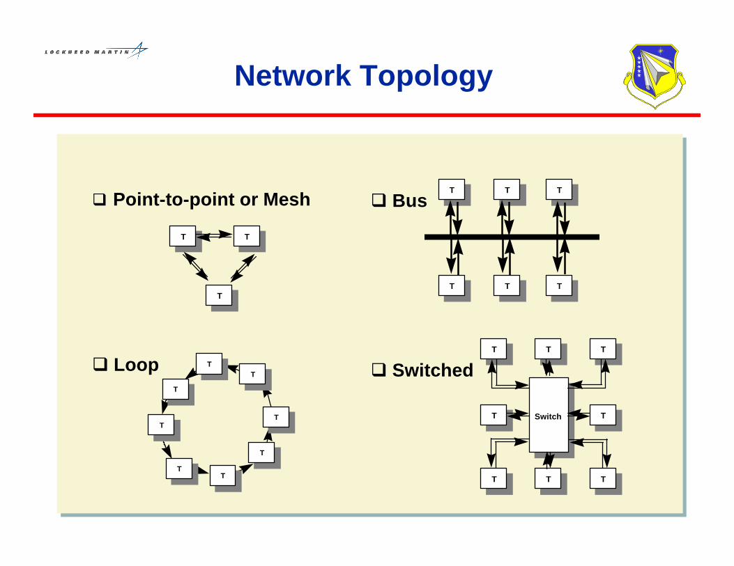
Benchmark 155 Mbps ATMOver 1553 Cable
• Measurement Method√ Standard UTP Cat. 5 Cable Compared to 1553 Cable√ Differing Cable Lengths
−UTP5 (13 and 63 Feet)−1553 (5,10,50,110,150 + 4’ for Converters) & Couplers where Applicable
√ No Impedance Matching for 1553 Cable
√ Average of 5 Runs√ Large Directory and Single File Transfers Under Windows NT
− MS Office Directory (68 MB)− Zipped Single File (60 MB)
√ TTCP Program, Standard Network Test

• 1553 Cable Works for Both ATM and Fast Ethernet– UTP5 and 1553 Cable Results Nearly Identical
• Limiting Factor for File Transfers is OperatingSystem Overhead and Hard Disk Speed
• Impedance Matching is not a Factor Except for LongCable Runs (Ethernet > 100 feet, ATM > 150 feet)
Benchmark Conclusions
Existing Cable is Not an Issue inthe Design of a Faster Network

ATM Test Configuration
1553/BB-Side
1553/BA-Side
ATM (STS-3c)
Actual A/C LRUsand BladeAntenna (Block 50with ARC-182Radio)
Blade Antenna
ControlSignals
MUX Assemblies RedundantMUX Assembly
Bi-directionalATM Traffic(Benchmark102-107 Mb/s)
ARC -182UHF/VHF
Radio
Adjacent Wires Inside Connector
DisconnectedX
0.5 voltspeak-to-peak
STS Synchronous Transfer Signaling
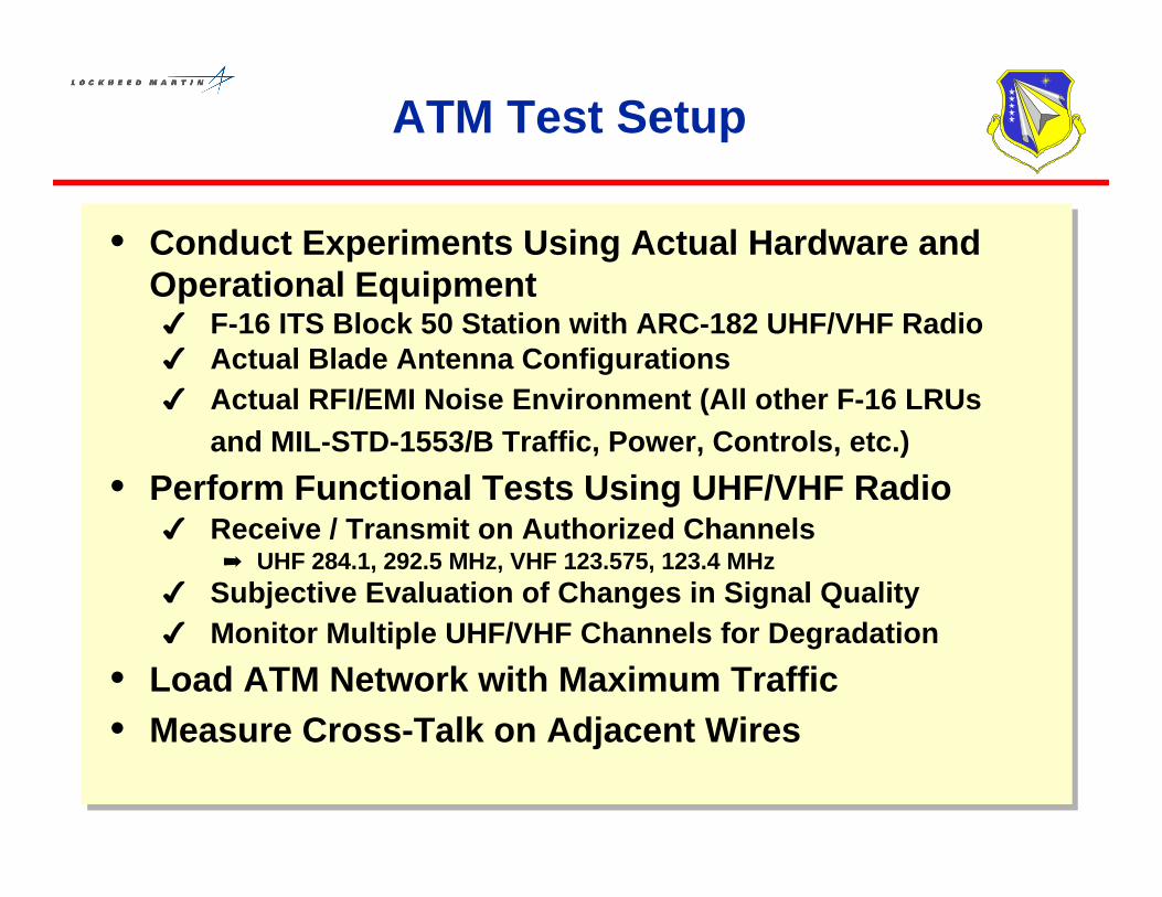
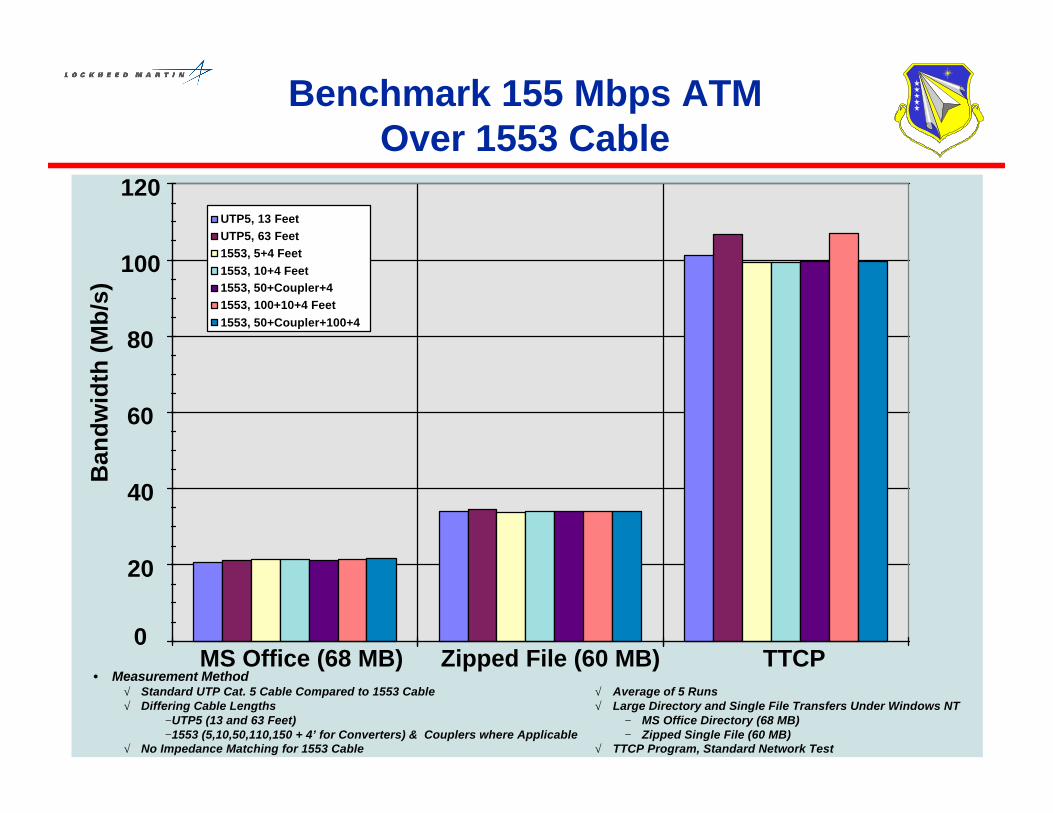
ATM Test Setup
• Conduct Experiments Using Actual Hardware andOperational Equipment4 F-16 ITS Block 50 Station with ARC-182 UHF/VHF Radio4 Actual Blade Antenna Configurations4 Actual RFI/EMI Noise Environment (All other F-16 LRUs
and MIL-STD-1553/B Traffic, Power, Controls, etc.)
• Perform Functional Tests Using UHF/VHF Radio4 Receive / Transmit on Authorized Channels
á UHF 284.1, 292.5 MHz, VHF 123.575, 123.4 MHz4 Subjective Evaluation of Changes in Signal Quality4 Monitor Multiple UHF/VHF Channels for Degradation
• Load ATM Network with Maximum Traffic• Measure Cross-Talk on Adjacent Wires

ATM Test Results
• Subjective Evaluations4 No Change in Signal Quality in VHF or UHF4 No Change at Cockpit or at Remote Site4 No Interference on Monitored Channels
• Objective Evaluations4 No Cell-Drops or Loss of Data on ATM Network4 Crosstalk Measurement - Peak-to-Peak Voltage
Average Signal Noise Increase: 18-20 mvMeasured Noise (Before ATM Applied): 39-42 mv
RFI and EMI Can Be Managed

ATM Test: Post Analysis
l Cable Noise On the Aircraft is Expected to Be LessThan the System Integration Lab (SIL) Test Station4 Shields of the 1553B Cables Inside the Test Station Were
Ungrounded for Ease of Connection to the Station4 In the F-16, Both Ends of MUX Cable Shields Are Grounded4 In the F-16, MUX Cable is Grounded at the Backshell of
Every Disconnect
l Actual F-16 vs the SIL Test Station:4 The Average Noise Measured on the F-16 Aircraft Could Be
1/3 Lower Than That Measured on STS4 The Resulting Average Crosstalk Noise is Expected to be 1/2
that Measured on the STS

Summary
• Legacy Aircraft Are Implementing OpenSystem Standards4 Transition to Open System Standards for Legacy Aircraft
Avionics has Started and Will Accelerate (LRUs, Networks)4 DoD Acquisition Processes and Strategies Are Working on
Legacy Aircraft Product Lines
• Evolving Fielded Weapon Systems to OpenSystem Approaches Is the Challenge4 Need Champions in the Logistics Support Communities4 Need Sustained Development Funding for Aircraft
Infrastructure Evolution (Flight Test, Tech Demos)

Executive SummaryMikel J. Harris
Open System Architecturefor Legacy Aircraft
Open System Architecturefor Legacy Aircraft

‘92 ‘94 ‘96 ‘98 ‘00 ‘02 ‘04 ‘06 ‘08 ‘10 ‘12 ‘14 ‘16 ‘18 ‘20
1000
0
2000
3000
4000
5000
6000
Air
craf
t In
ven
tory
A/V-8B
A-7E
F-111
F-117
F-14
A-6E
F/A-18A/B F/A-18C/D
F/A-18E/F
JSF-N
JSF-AFF-22F-16C/DF-16A/B
F-15EF-15A/B/C/D
F-4G A-10
F-4
The Majority of Our TacticalForce Through 2020 Will Be Legacy Aircraft

Nu
mb
er O
f A
ircr
aft
0
5
10
15
20
25
30
35
40
45
50
Ave
rag
e A
ge
(Yea
rs)
200
400
600
800
1000
1200
1400
1600
FY 95 FY 00 FY 05 FY 10 FY 15
C-130
C-130J
KC-135
KC-10C-17C-141
C-5
Strategic & Tactical AirliftInventory Projections

F-16 Dominates the USAFForce Structure Until JSF Introduction
25
20
15
10
5
01995 1996 1997 1998 1999 2000 2001 2002 2003 2004 2005 2006 2007 2008 2009 2010
Years
ANG/AFR Forces Total Forces
Active Forces
25
20
15
10
5
01995 1996 1997 1998 1999 2000 2001 2002 2003 2004 2005 2006 2007 2008 2009 2010
Years
Total Forces
F-16 Forces
Legacy Aircraft Modernization Window

• The User Must Accomplish More With His Fleet of Existing Aircraft– Limited Funds and Aging Fleet (Average Age of All Fighters 18yrs @ 2010)
• Modifications Must be Incremental, Modular, and Rapid– Available Funding Profiles Will Not Allow Major Physical Upgrades– Politics are the Enemy of Long Programs
• We Must Work Within the Aircraft Physical Architecture (Wiring, Cooling, etc.)– Physical Changes Drive Mod Cost Exponential (Kills Program)
• No Software Modification is Minor– Test and Validation are the Cost Drivers (Not Design and Coding)
• Logistics Tail Plays Key Role in Upgrade/Mod Decisions (Have Final Vote)– The Cost Here Continues Throughout the Life Cycle (Key Words - 1 Level Maintenance)
• Commercial Market Drives the Electronics Industry (Not DoD)– We Must Work Within This Environment for Affordability– Key Element is Rapid Commercial Parts Obsolescence (Not Environmental)
• We Must Work Within the Avionics Vendor Chain of Capability– Vendors Must Protect Their Ownership of Functionality (i.e. CNI, EW, Radar, etc.)– DoD and Primes Must Prevent “Vendor Vanish”
Avionics Upgrade Environment

Open System Studies
Studies Were Directed Towards Legacy Avionics Architecture…
…to Evolve Aircraft Weapons Systems to Open Systems Standards.
Studies and Analyses Summary of Preliminary Results
Global Reach Open Network Aircraft Weapon Systems and SupportSystems Should Be Directly to the MilitaryNetworks for Ground Operations Repair,Maintenance, and Support
Common Real Time Operating SystemInterface for Software
Commercial Real-Time OperatingSystems Have Been and Can Be Adapted
Open Network Architecture Protocols Asynchronous Transfer Mode and FibreChannel Are Interim Network Solutions(Integrated Sensor System Program toDetermine Radar Protocols)
Open Standards and Interface Commercial Open Standards AreAvailable to Replace Existing LRUs

• The Big Pay-off Is in Opening the Federated Architecture
• DoD Investments Are Required– Open Standard for Mil-Std-1553 Emulation on COTS Network
– Open Interface Standard for Peer-to-Peer Military Protocols
– Validation and Flight Test
• The Driving Cost Factors Are Group A Aircraft Changesand the Software Impacts to Existing Avionics– Must Address How to Minimize These Costs for Each Aircraft
– Configuration
– Develop an Upgrade Plan for Modernization
Conclusions and Recommendations