Embed Size (px)
Citation preview

The OpenGL R© Graphics System:A Specification
(Version 4.4 (Compatibility Profile) - March 19,2014)
Mark SegalKurt Akeley
Editor (version 1.1): Chris FrazierEditor (versions 1.2-4.4 ): Jon Leech
Editor (version 2.0): Pat Brown
Copyright c© 2006-2014 The Khronos Group Inc. All Rights Reserved.
This specification is protected by copyright laws and contains material proprietaryto the Khronos Group, Inc. It or any components may not be reproduced, repub-lished, distributed, transmitted, displayed, broadcast or otherwise exploited in anymanner without the express prior written permission of Khronos Group. You mayuse this specification for implementing the functionality therein, without altering orremoving any trademark, copyright or other notice from the specification, but thereceipt or possession of this specification does not convey any rights to reproduce,disclose, or distribute its contents, or to manufacture, use, or sell anything that itmay describe, in whole or in part.
Khronos Group grants express permission to any current Promoter, Contributoror Adopter member of Khronos to copy and redistribute UNMODIFIED versionsof this specification in any fashion, provided that NO CHARGE is made for thespecification and the latest available update of the specification for any versionof the API is used whenever possible. Such distributed specification may be re-formatted AS LONG AS the contents of the specification are not changed in anyway. The specification may be incorporated into a product that is sold as long assuch product includes significant independent work developed by the seller. A linkto the current version of this specification on the Khronos Group web-site shouldbe included whenever possible with specification distributions.
Khronos Group makes no, and expressly disclaims any, representations or war-ranties, express or implied, regarding this specification, including, without limita-tion, any implied warranties of merchantability or fitness for a particular purposeor non-infringement of any intellectual property. Khronos Group makes no, andexpressly disclaims any, warranties, express or implied, regarding the correctness,accuracy, completeness, timeliness, and reliability of the specification. Under nocircumstances will the Khronos Group, or any of its Promoters, Contributors orMembers or their respective partners, officers, directors, employees, agents or rep-resentatives be liable for any damages, whether direct, indirect, special or conse-quential damages for lost revenues, lost profits, or otherwise, arising from or inconnection with these materials.
Khronos is a trademark of The Khronos Group Inc. OpenGL is a registered trade-mark, and OpenGL ES is a trademark, of Silicon Graphics International.
Contents
1 Introduction 11.1 Formatting of the OpenGL Specification . . . . . . . . . . . . . . 1
1.1.1 Formatting of the Compatibility Profile . . . . . . . . . . 11.1.2 Formatting of Optional Features . . . . . . . . . . . . . . 1
1.2 What is the OpenGL Graphics System? . . . . . . . . . . . . . . 21.2.1 Programmer’s View of OpenGL . . . . . . . . . . . . . . 21.2.2 Implementor’s View of OpenGL . . . . . . . . . . . . . . 21.2.3 Our View . . . . . . . . . . . . . . . . . . . . . . . . . . 31.2.4 Fixed-function Hardware and the Compatibility Profile . . 31.2.5 The Deprecation Model . . . . . . . . . . . . . . . . . . 3
1.3 Related APIs . . . . . . . . . . . . . . . . . . . . . . . . . . . . 41.3.1 OpenGL Shading Language . . . . . . . . . . . . . . . . 41.3.2 OpenGL ES . . . . . . . . . . . . . . . . . . . . . . . . . 41.3.3 OpenGL ES Shading Language . . . . . . . . . . . . . . 51.3.4 WebGL . . . . . . . . . . . . . . . . . . . . . . . . . . . 51.3.5 Window System Bindings . . . . . . . . . . . . . . . . . 61.3.6 OpenCL . . . . . . . . . . . . . . . . . . . . . . . . . . . 6
1.4 Filing Bug Reports . . . . . . . . . . . . . . . . . . . . . . . . . 7
2 OpenGL Fundamentals 82.1 Execution Model . . . . . . . . . . . . . . . . . . . . . . . . . . 82.2 Command Syntax . . . . . . . . . . . . . . . . . . . . . . . . . . 10
2.2.1 Data Conversion For State-Setting Commands . . . . . . 122.2.2 Data Conversions For State Query Commands . . . . . . 14
2.3 Command Execution . . . . . . . . . . . . . . . . . . . . . . . . 152.3.1 Errors . . . . . . . . . . . . . . . . . . . . . . . . . . . . 152.3.2 Flush and Finish . . . . . . . . . . . . . . . . . . . . . . 182.3.3 Numeric Representation and Computation . . . . . . . . . 182.3.4 Fixed-Point Data Conversions . . . . . . . . . . . . . . . 22
i
CONTENTS ii
2.4 Rendering Commands . . . . . . . . . . . . . . . . . . . . . . . 242.5 Context State . . . . . . . . . . . . . . . . . . . . . . . . . . . . 24
2.5.1 Generic Context State Queries . . . . . . . . . . . . . . . 252.6 Objects and the Object Model . . . . . . . . . . . . . . . . . . . 25
2.6.1 Object Management . . . . . . . . . . . . . . . . . . . . 252.6.2 Buffer Objects . . . . . . . . . . . . . . . . . . . . . . . 272.6.3 Shader Objects . . . . . . . . . . . . . . . . . . . . . . . 272.6.4 Program Objects . . . . . . . . . . . . . . . . . . . . . . 272.6.5 Program Pipeline Objects . . . . . . . . . . . . . . . . . 272.6.6 Texture Objects . . . . . . . . . . . . . . . . . . . . . . . 272.6.7 Sampler Objects . . . . . . . . . . . . . . . . . . . . . . 282.6.8 Renderbuffer Objects . . . . . . . . . . . . . . . . . . . . 282.6.9 Framebuffer Objects . . . . . . . . . . . . . . . . . . . . 282.6.10 Vertex Array Objects . . . . . . . . . . . . . . . . . . . . 292.6.11 Transform Feedback Objects . . . . . . . . . . . . . . . . 292.6.12 Query Objects . . . . . . . . . . . . . . . . . . . . . . . 292.6.13 Sync Objects . . . . . . . . . . . . . . . . . . . . . . . . 292.6.14 Display Lists . . . . . . . . . . . . . . . . . . . . . . . . 30
3 Dataflow Model 31
4 Event Model 344.1 Sync Objects and Fences . . . . . . . . . . . . . . . . . . . . . . 34
4.1.1 Waiting for Sync Objects . . . . . . . . . . . . . . . . . . 364.1.2 Signaling . . . . . . . . . . . . . . . . . . . . . . . . . . 384.1.3 Sync Object Queries . . . . . . . . . . . . . . . . . . . . 38
4.2 Query Objects and Asynchronous Queries . . . . . . . . . . . . . 394.2.1 Query Object Queries . . . . . . . . . . . . . . . . . . . 43
4.3 Time Queries . . . . . . . . . . . . . . . . . . . . . . . . . . . . 46
5 Shared Objects and Multiple Contexts 485.1 Object Deletion Behavior . . . . . . . . . . . . . . . . . . . . . . 49
5.1.1 Side Effects of Shared Context Destruction . . . . . . . . 495.1.2 Automatic Unbinding of Deleted Objects . . . . . . . . . 495.1.3 Deleted Object and Object Name Lifetimes . . . . . . . . 49
5.2 Sync Objects and Multiple Contexts . . . . . . . . . . . . . . . . 505.3 Propagating Changes to Objects . . . . . . . . . . . . . . . . . . 50
5.3.1 Determining Completion of Changes to an object . . . . . 515.3.2 Definitions . . . . . . . . . . . . . . . . . . . . . . . . . 525.3.3 Rules . . . . . . . . . . . . . . . . . . . . . . . . . . . . 52
OpenGL 4.4 (Compatibility Profile) - March 19, 2014
CONTENTS iii
6 Buffer Objects 546.1 Creating and Binding Buffer Objects . . . . . . . . . . . . . . . . 55
6.1.1 Binding Buffer Objects to Indexed Targets . . . . . . . . . 576.2 Creating and Modifying Buffer Object Data Stores . . . . . . . . 60
6.2.1 Clearing Buffer Object Data Stores . . . . . . . . . . . . 656.3 Mapping and Unmapping Buffer Data . . . . . . . . . . . . . . . 66
6.3.1 Unmapping Buffers . . . . . . . . . . . . . . . . . . . . . 716.3.2 Effects of Mapping Buffers on Other GL Commands . . . 71
6.4 Effects of Accessing Outside Buffer Bounds . . . . . . . . . . . . 726.5 Invalidating Buffer Data . . . . . . . . . . . . . . . . . . . . . . 726.6 Copying Between Buffers . . . . . . . . . . . . . . . . . . . . . . 736.7 Buffer Object Queries . . . . . . . . . . . . . . . . . . . . . . . . 74
6.7.1 Indexed Buffer Object Limits and Binding Queries . . . . 756.8 Buffer Object State . . . . . . . . . . . . . . . . . . . . . . . . . 77
7 Programs and Shaders 787.1 Shader Objects . . . . . . . . . . . . . . . . . . . . . . . . . . . 797.2 Shader Binaries . . . . . . . . . . . . . . . . . . . . . . . . . . . 827.3 Program Objects . . . . . . . . . . . . . . . . . . . . . . . . . . 83
7.3.1 Program Interfaces . . . . . . . . . . . . . . . . . . . . . 907.4 Program Pipeline Objects . . . . . . . . . . . . . . . . . . . . . . 109
7.4.1 Shader Interface Matching . . . . . . . . . . . . . . . . . 1127.4.2 Program Pipeline Object State . . . . . . . . . . . . . . . 115
7.5 Program Binaries . . . . . . . . . . . . . . . . . . . . . . . . . . 1167.6 Uniform Variables . . . . . . . . . . . . . . . . . . . . . . . . . . 118
7.6.1 Loading Uniform Variables In The Default Uniform Block 1257.6.2 Uniform Blocks . . . . . . . . . . . . . . . . . . . . . . . 1297.6.3 Uniform Buffer Object Bindings . . . . . . . . . . . . . . 132
7.7 Atomic Counter Buffers . . . . . . . . . . . . . . . . . . . . . . . 1337.7.1 Atomic Counter Buffer Object Storage . . . . . . . . . . 1347.7.2 Atomic Counter Buffer Bindings . . . . . . . . . . . . . . 134
7.8 Shader Buffer Variables and Shader Storage Blocks . . . . . . . . 1357.9 Subroutine Uniform Variables . . . . . . . . . . . . . . . . . . . 1377.10 Samplers . . . . . . . . . . . . . . . . . . . . . . . . . . . . . . 1407.11 Images . . . . . . . . . . . . . . . . . . . . . . . . . . . . . . . . 1417.12 Shader Memory Access . . . . . . . . . . . . . . . . . . . . . . . 142
7.12.1 Shader Memory Access Ordering . . . . . . . . . . . . . 1427.12.2 Shader Memory Access Synchronization . . . . . . . . . 144
7.13 Shader, Program, and Program Pipeline Queries . . . . . . . . . . 1487.14 Required State . . . . . . . . . . . . . . . . . . . . . . . . . . . . 157
OpenGL 4.4 (Compatibility Profile) - March 19, 2014
CONTENTS iv
8 Textures and Samplers 1598.1 Texture Objects . . . . . . . . . . . . . . . . . . . . . . . . . . . 1628.2 Sampler Objects . . . . . . . . . . . . . . . . . . . . . . . . . . . 1668.3 Sampler Object Queries . . . . . . . . . . . . . . . . . . . . . . . 1708.4 Pixel Rectangles . . . . . . . . . . . . . . . . . . . . . . . . . . . 171
8.4.1 Pixel Storage Modes and Pixel Buffer Objects . . . . . . . 1718.4.2 The Imaging Subset . . . . . . . . . . . . . . . . . . . . 1728.4.3 Pixel Transfer Modes . . . . . . . . . . . . . . . . . . . . 1738.4.4 Transfer of Pixel Rectangles . . . . . . . . . . . . . . . . 1928.4.5 Pixel Transfer Operations . . . . . . . . . . . . . . . . . 205
8.5 Texture Image Specification . . . . . . . . . . . . . . . . . . . . 2158.5.1 Required Texture Formats . . . . . . . . . . . . . . . . . 2198.5.2 Encoding of Special Internal Formats . . . . . . . . . . . 2198.5.3 Texture Image Structure . . . . . . . . . . . . . . . . . . 224
8.6 Alternate Texture Image Specification Commands . . . . . . . . . 2318.6.1 Texture Copying Feedback Loops . . . . . . . . . . . . . 237
8.7 Compressed Texture Images . . . . . . . . . . . . . . . . . . . . 2378.8 Multisample Textures . . . . . . . . . . . . . . . . . . . . . . . . 2448.9 Buffer Textures . . . . . . . . . . . . . . . . . . . . . . . . . . . 2468.10 Texture Parameters . . . . . . . . . . . . . . . . . . . . . . . . . 2498.11 Texture Queries . . . . . . . . . . . . . . . . . . . . . . . . . . . 253
8.11.1 Active Texture . . . . . . . . . . . . . . . . . . . . . . . 2538.11.2 Texture Parameter Queries . . . . . . . . . . . . . . . . . 2538.11.3 Texture Level Parameter Queries . . . . . . . . . . . . . . 2548.11.4 Texture Image Queries . . . . . . . . . . . . . . . . . . . 256
8.12 Depth Component Textures . . . . . . . . . . . . . . . . . . . . . 2598.13 Cube Map Texture Selection . . . . . . . . . . . . . . . . . . . . 260
8.13.1 Seamless Cube Map Filtering . . . . . . . . . . . . . . . 2608.14 Texture Minification . . . . . . . . . . . . . . . . . . . . . . . . 261
8.14.1 Scale Factor and Level of Detail . . . . . . . . . . . . . . 2628.14.2 Coordinate Wrapping and Texel Selection . . . . . . . . . 2648.14.3 Mipmapping . . . . . . . . . . . . . . . . . . . . . . . . 2698.14.4 Manual Mipmap Generation . . . . . . . . . . . . . . . . 2718.14.5 Automatic Mipmap Generation . . . . . . . . . . . . . . 272
8.15 Texture Magnification . . . . . . . . . . . . . . . . . . . . . . . . 2738.16 Combined Depth/Stencil Textures . . . . . . . . . . . . . . . . . 2738.17 Texture Completeness . . . . . . . . . . . . . . . . . . . . . . . . 273
8.17.1 Effects of Sampler Objects on Texture Completeness . . . 2758.17.2 Effects of Completeness on Texture Application . . . . . . 2758.17.3 Effects of Completeness on Texture Image Specification . 275
OpenGL 4.4 (Compatibility Profile) - March 19, 2014
CONTENTS v
8.18 Texture Views . . . . . . . . . . . . . . . . . . . . . . . . . . . . 2768.19 Immutable-Format Texture Images . . . . . . . . . . . . . . . . . 2808.20 Invalidating Texture Image Data . . . . . . . . . . . . . . . . . . 2858.21 Clearing Texture Image Data . . . . . . . . . . . . . . . . . . . . 2868.22 Texture State and Proxy State . . . . . . . . . . . . . . . . . . . . 2888.23 Texture Comparison Modes . . . . . . . . . . . . . . . . . . . . . 291
8.23.1 Depth Texture Comparison Mode . . . . . . . . . . . . . 2918.24 sRGB Texture Color Conversion . . . . . . . . . . . . . . . . . . 2938.25 Shared Exponent Texture Color Conversion . . . . . . . . . . . . 2948.26 Texture Image Loads and Stores . . . . . . . . . . . . . . . . . . 294
8.26.1 Image Unit Queries . . . . . . . . . . . . . . . . . . . . . 303
9 Framebuffers and Framebuffer Objects 3049.1 Framebuffer Overview . . . . . . . . . . . . . . . . . . . . . . . 3049.2 Binding and Managing Framebuffer Objects . . . . . . . . . . . . 306
9.2.1 Framebuffer Object Parameters . . . . . . . . . . . . . . 3109.2.2 Attaching Images to Framebuffer Objects . . . . . . . . . 3119.2.3 Framebuffer Object Queries . . . . . . . . . . . . . . . . 3129.2.4 Renderbuffer Objects . . . . . . . . . . . . . . . . . . . . 3159.2.5 Required Renderbuffer Formats . . . . . . . . . . . . . . 3189.2.6 Renderbuffer Object Queries . . . . . . . . . . . . . . . . 3189.2.7 Attaching Renderbuffer Images to a Framebuffer . . . . . 3199.2.8 Attaching Texture Images to a Framebuffer . . . . . . . . 321
9.3 Feedback Loops Between Textures and the Framebuffer . . . . . . 3259.3.1 Rendering Feedback Loops . . . . . . . . . . . . . . . . . 3259.3.2 Texture Copying Feedback Loops . . . . . . . . . . . . . 327
9.4 Framebuffer Completeness . . . . . . . . . . . . . . . . . . . . . 3279.4.1 Framebuffer Attachment Completeness . . . . . . . . . . 3289.4.2 Whole Framebuffer Completeness . . . . . . . . . . . . . 3299.4.3 Required Framebuffer Formats . . . . . . . . . . . . . . . 3329.4.4 Effects of Framebuffer Completeness on Framebuffer Op-
erations . . . . . . . . . . . . . . . . . . . . . . . . . . . 3329.4.5 Effects of Framebuffer State on Framebuffer Dependent
Values . . . . . . . . . . . . . . . . . . . . . . . . . . . . 3339.5 Mapping between Pixel and Element in Attached Image . . . . . . 3349.6 Conversion to Framebuffer-Attachable Image Components . . . . 3349.7 Conversion to RGBA Values . . . . . . . . . . . . . . . . . . . . 3359.8 Layered Framebuffers . . . . . . . . . . . . . . . . . . . . . . . . 335
OpenGL 4.4 (Compatibility Profile) - March 19, 2014
CONTENTS vi
10 Vertex Specification and Drawing Commands 33710.1 Primitive Types . . . . . . . . . . . . . . . . . . . . . . . . . . . 341
10.1.1 Points . . . . . . . . . . . . . . . . . . . . . . . . . . . . 34110.1.2 Line Strips . . . . . . . . . . . . . . . . . . . . . . . . . 34210.1.3 Line Loops . . . . . . . . . . . . . . . . . . . . . . . . . 34210.1.4 Separate Lines . . . . . . . . . . . . . . . . . . . . . . . 34210.1.5 Polygons . . . . . . . . . . . . . . . . . . . . . . . . . . 34210.1.6 Triangle Strips . . . . . . . . . . . . . . . . . . . . . . . 34310.1.7 Triangle Fans . . . . . . . . . . . . . . . . . . . . . . . . 34310.1.8 Separate Triangles . . . . . . . . . . . . . . . . . . . . . 34410.1.9 Quadrilateral (quad) strips . . . . . . . . . . . . . . . . . 34410.1.10 Separate Quadrilaterals . . . . . . . . . . . . . . . . . . . 34410.1.11 Lines with Adjacency . . . . . . . . . . . . . . . . . . . 34510.1.12 Line Strips with Adjacency . . . . . . . . . . . . . . . . . 34610.1.13 Triangles with Adjacency . . . . . . . . . . . . . . . . . 34610.1.14 Triangle Strips with Adjacency . . . . . . . . . . . . . . . 34710.1.15 Separate Patches . . . . . . . . . . . . . . . . . . . . . . 34810.1.16 General Considerations For Polygon Primitives . . . . . . 34910.1.17 Polygon Edges . . . . . . . . . . . . . . . . . . . . . . . 349
10.2 Current Vertex Attribute Values . . . . . . . . . . . . . . . . . . . 35010.2.1 Current Generic Attributes . . . . . . . . . . . . . . . . . 35010.2.2 Current Conventional Attributes . . . . . . . . . . . . . . 35210.2.3 Vertex Attribute Queries . . . . . . . . . . . . . . . . . . 35510.2.4 Required State . . . . . . . . . . . . . . . . . . . . . . . 355
10.3 Vertex Arrays . . . . . . . . . . . . . . . . . . . . . . . . . . . . 35610.3.1 Specifying Arrays for Generic Vertex Attributes . . . . . . 35610.3.2 Specifying Arrays for Fixed-Function Attributes . . . . . 36210.3.3 Vertex Attribute Divisors . . . . . . . . . . . . . . . . . . 36510.3.4 Transferring Array Elements . . . . . . . . . . . . . . . . 36510.3.5 Primitive Restart . . . . . . . . . . . . . . . . . . . . . . 36610.3.6 Robust Buffer Access . . . . . . . . . . . . . . . . . . . . 36710.3.7 Packed Vertex Data Formats . . . . . . . . . . . . . . . . 36710.3.8 Vertex Arrays in Buffer Objects . . . . . . . . . . . . . . 36810.3.9 Array Indices in Buffer Objects . . . . . . . . . . . . . . 36910.3.10 Indirect Commands in Buffer Objects . . . . . . . . . . . 370
10.4 Vertex Array Objects . . . . . . . . . . . . . . . . . . . . . . . . 37010.5 Drawing Commands Using Vertex Arrays . . . . . . . . . . . . . 372
10.5.1 Interleaved Arrays . . . . . . . . . . . . . . . . . . . . . 38210.6 Vertex Array and Vertex Array Object Queries . . . . . . . . . . . 38410.7 Required State . . . . . . . . . . . . . . . . . . . . . . . . . . . . 386
OpenGL 4.4 (Compatibility Profile) - March 19, 2014
CONTENTS vii
10.8 Drawing Commands Using Begin and End . . . . . . . . . . . . 38710.8.1 Transferring Vertices With Vertex Commands . . . . . . . 38710.8.2 Transferring Vertices With Vertex Attribute Zero . . . . . 38810.8.3 Bundling Attributes With Vertex Commands . . . . . . . 38810.8.4 Transferring Vertices With ArrayElement . . . . . . . . 38810.8.5 Commands Allowed Between Begin and End . . . . . . . 390
10.9 Rectangles . . . . . . . . . . . . . . . . . . . . . . . . . . . . . . 39110.10Conditional Rendering . . . . . . . . . . . . . . . . . . . . . . . 392
11 Programmable Vertex Processing 39411.1 Vertex Shaders . . . . . . . . . . . . . . . . . . . . . . . . . . . 394
11.1.1 Vertex Attributes . . . . . . . . . . . . . . . . . . . . . . 39411.1.2 Vertex Shader Variables . . . . . . . . . . . . . . . . . . 40011.1.3 Shader Execution . . . . . . . . . . . . . . . . . . . . . . 405
11.2 Tessellation . . . . . . . . . . . . . . . . . . . . . . . . . . . . . 41711.2.1 Tessellation Control Shaders . . . . . . . . . . . . . . . . 41811.2.2 Tessellation Primitive Generation . . . . . . . . . . . . . 42311.2.3 Tessellation Evaluation Shaders . . . . . . . . . . . . . . 432
11.3 Geometry Shaders . . . . . . . . . . . . . . . . . . . . . . . . . . 43711.3.1 Geometry Shader Input Primitives . . . . . . . . . . . . . 43811.3.2 Geometry Shader Output Primitives . . . . . . . . . . . . 44011.3.3 Geometry Shader Variables . . . . . . . . . . . . . . . . . 44011.3.4 Geometry Shader Execution Environment . . . . . . . . . 441
12 Fixed-Function Vertex Processing 44812.1 Fixed-Function Vertex Transformations . . . . . . . . . . . . . . 448
12.1.1 Matrices . . . . . . . . . . . . . . . . . . . . . . . . . . . 44912.1.2 Normal Transformation . . . . . . . . . . . . . . . . . . . 45512.1.3 Generating Texture Coordinates . . . . . . . . . . . . . . 456
12.2 Fixed-Function Vertex Lighting and Coloring . . . . . . . . . . . 45912.2.1 Lighting . . . . . . . . . . . . . . . . . . . . . . . . . . . 46012.2.2 Lighting Parameter Specification . . . . . . . . . . . . . . 46512.2.3 ColorMaterial . . . . . . . . . . . . . . . . . . . . . . . 46812.2.4 Lighting Parameter Queries . . . . . . . . . . . . . . . . 46812.2.5 Lighting State . . . . . . . . . . . . . . . . . . . . . . . . 47012.2.6 Color Index Lighting . . . . . . . . . . . . . . . . . . . . 470
13 Fixed-Function Vertex Post-Processing 47213.1 Clamping or Masking . . . . . . . . . . . . . . . . . . . . . . . . 47313.2 Transform Feedback . . . . . . . . . . . . . . . . . . . . . . . . 473
OpenGL 4.4 (Compatibility Profile) - March 19, 2014
CONTENTS viii
13.2.1 Transform Feedback Objects . . . . . . . . . . . . . . . . 47413.2.2 Transform Feedback Primitive Capture . . . . . . . . . . 47613.2.3 Transform Feedback Draw Operations . . . . . . . . . . . 480
13.3 Primitive Queries . . . . . . . . . . . . . . . . . . . . . . . . . . 48113.4 Flatshading . . . . . . . . . . . . . . . . . . . . . . . . . . . . . 48213.5 Primitive Clipping . . . . . . . . . . . . . . . . . . . . . . . . . . 484
13.5.1 Color and Associated Data Clipping . . . . . . . . . . . . 48713.5.2 Clip Plane Queries . . . . . . . . . . . . . . . . . . . . . 487
13.6 Coordinate Transformations . . . . . . . . . . . . . . . . . . . . 48813.6.1 Controlling the Viewport . . . . . . . . . . . . . . . . . . 488
13.7 Final Color Processing . . . . . . . . . . . . . . . . . . . . . . . 491
14 Fixed-Function Primitive Assembly and Rasterization 49314.1 Discarding Primitives Before Rasterization . . . . . . . . . . . . 49514.2 Invariance . . . . . . . . . . . . . . . . . . . . . . . . . . . . . . 49514.3 Antialiasing . . . . . . . . . . . . . . . . . . . . . . . . . . . . . 495
14.3.1 Multisampling . . . . . . . . . . . . . . . . . . . . . . . 49714.4 Points . . . . . . . . . . . . . . . . . . . . . . . . . . . . . . . . 500
14.4.1 Basic Point Rasterization . . . . . . . . . . . . . . . . . . 50214.4.2 Point Rasterization State . . . . . . . . . . . . . . . . . . 50614.4.3 Point Multisample Rasterization . . . . . . . . . . . . . . 506
14.5 Line Segments . . . . . . . . . . . . . . . . . . . . . . . . . . . 50714.5.1 Basic Line Segment Rasterization . . . . . . . . . . . . . 50714.5.2 Other Line Segment Features . . . . . . . . . . . . . . . . 51014.5.3 Line Rasterization State . . . . . . . . . . . . . . . . . . 51314.5.4 Line Multisample Rasterization . . . . . . . . . . . . . . 513
14.6 Polygons . . . . . . . . . . . . . . . . . . . . . . . . . . . . . . 51314.6.1 Basic Polygon Rasterization . . . . . . . . . . . . . . . . 51414.6.2 Stippling . . . . . . . . . . . . . . . . . . . . . . . . . . 51614.6.3 Antialiasing . . . . . . . . . . . . . . . . . . . . . . . . . 51714.6.4 Options Controlling Polygon Rasterization . . . . . . . . 51814.6.5 Depth Offset . . . . . . . . . . . . . . . . . . . . . . . . 51814.6.6 Polygon Multisample Rasterization . . . . . . . . . . . . 52014.6.7 Polygon Rasterization State . . . . . . . . . . . . . . . . 520
14.7 Current Raster Position . . . . . . . . . . . . . . . . . . . . . . . 52114.8 Bitmaps . . . . . . . . . . . . . . . . . . . . . . . . . . . . . . . 52414.9 Early Per-Fragment Tests . . . . . . . . . . . . . . . . . . . . . . 526
OpenGL 4.4 (Compatibility Profile) - March 19, 2014
CONTENTS ix
15 Programmable Fragment Processing 52715.1 Fragment Shader Variables . . . . . . . . . . . . . . . . . . . . . 52715.2 Shader Execution . . . . . . . . . . . . . . . . . . . . . . . . . . 529
15.2.1 Texture Access . . . . . . . . . . . . . . . . . . . . . . . 52915.2.2 Shader Inputs . . . . . . . . . . . . . . . . . . . . . . . . 52915.2.3 Shader Outputs . . . . . . . . . . . . . . . . . . . . . . . 53215.2.4 Early Fragment Tests . . . . . . . . . . . . . . . . . . . . 536
16 Fixed-Function Fragment Processing 53716.1 Texture Environments and Texture Functions . . . . . . . . . . . 537
16.1.1 Texture Environment Queries . . . . . . . . . . . . . . . 54316.2 Texture Application . . . . . . . . . . . . . . . . . . . . . . . . . 54316.3 Color Sum . . . . . . . . . . . . . . . . . . . . . . . . . . . . . . 54616.4 Fog . . . . . . . . . . . . . . . . . . . . . . . . . . . . . . . . . 546
17 Writing Fragments and Samples to the Framebuffer 54917.1 Antialiasing Application . . . . . . . . . . . . . . . . . . . . . . 54917.2 Multisample Point Fade . . . . . . . . . . . . . . . . . . . . . . . 55017.3 Per-Fragment Operations . . . . . . . . . . . . . . . . . . . . . . 550
17.3.1 Pixel Ownership Test . . . . . . . . . . . . . . . . . . . . 55117.3.2 Scissor Test . . . . . . . . . . . . . . . . . . . . . . . . . 55117.3.3 Multisample Fragment Operations . . . . . . . . . . . . . 55317.3.4 Alpha Test . . . . . . . . . . . . . . . . . . . . . . . . . 55517.3.5 Stencil Test . . . . . . . . . . . . . . . . . . . . . . . . . 55617.3.6 Depth Buffer Test . . . . . . . . . . . . . . . . . . . . . . 55717.3.7 Occlusion Queries . . . . . . . . . . . . . . . . . . . . . 55817.3.8 Blending . . . . . . . . . . . . . . . . . . . . . . . . . . 55917.3.9 sRGB Conversion . . . . . . . . . . . . . . . . . . . . . 56617.3.10 Dithering . . . . . . . . . . . . . . . . . . . . . . . . . . 56617.3.11 Logical Operation . . . . . . . . . . . . . . . . . . . . . 56717.3.12 Additional Multisample Fragment Operations . . . . . . . 569
17.4 Whole Framebuffer Operations . . . . . . . . . . . . . . . . . . . 57017.4.1 Selecting Buffers for Writing . . . . . . . . . . . . . . . . 57017.4.2 Fine Control of Buffer Updates . . . . . . . . . . . . . . 57417.4.3 Clearing the Buffers . . . . . . . . . . . . . . . . . . . . 57617.4.4 Invalidating Framebuffer Contents . . . . . . . . . . . . . 58017.4.5 The Accumulation Buffer . . . . . . . . . . . . . . . . . 581
OpenGL 4.4 (Compatibility Profile) - March 19, 2014
CONTENTS x
18 Drawing, Reading, and Copying Pixels 58318.1 Drawing Pixels . . . . . . . . . . . . . . . . . . . . . . . . . . . 583
18.1.1 Final Conversion . . . . . . . . . . . . . . . . . . . . . . 58418.1.2 Conversion to Fragments . . . . . . . . . . . . . . . . . . 58518.1.3 Pixel Rectangle Multisample Rasterization . . . . . . . . 58618.1.4 Writing to the Stencil or Depth/Stencil Buffers . . . . . . 586
18.2 Reading Pixels . . . . . . . . . . . . . . . . . . . . . . . . . . . 58718.2.1 Selecting Buffers for Reading . . . . . . . . . . . . . . . 58718.2.2 ReadPixels . . . . . . . . . . . . . . . . . . . . . . . . . 58918.2.3 Obtaining Pixels from the Framebuffer . . . . . . . . . . 59018.2.4 Conversion of RGBA values . . . . . . . . . . . . . . . . 59218.2.5 Conversion of Depth values . . . . . . . . . . . . . . . . 59218.2.6 Pixel Transfer Operations . . . . . . . . . . . . . . . . . 59218.2.7 Conversion to L . . . . . . . . . . . . . . . . . . . . . . . 59218.2.8 Final Conversion . . . . . . . . . . . . . . . . . . . . . . 59318.2.9 Placement in Pixel Pack Buffer or Client Memory . . . . . 594
18.3 Copying Pixels . . . . . . . . . . . . . . . . . . . . . . . . . . . 59418.3.1 Copying Pixel Rectangles . . . . . . . . . . . . . . . . . 59618.3.2 Blitting Pixel Rectangles . . . . . . . . . . . . . . . . . . 59918.3.3 Copying Between Images . . . . . . . . . . . . . . . . . 602
18.4 Pixel Draw and Read State . . . . . . . . . . . . . . . . . . . . . 605
19 Compute Shaders 60619.1 Compute Shader Variables . . . . . . . . . . . . . . . . . . . . . 608
20 Debug Output 60920.1 Debug Messages . . . . . . . . . . . . . . . . . . . . . . . . . . 61020.2 Debug Message Callback . . . . . . . . . . . . . . . . . . . . . . 61220.3 Debug Message Log . . . . . . . . . . . . . . . . . . . . . . . . 61320.4 Controlling Debug Messages . . . . . . . . . . . . . . . . . . . . 61320.5 Externally Generated Messages . . . . . . . . . . . . . . . . . . . 61520.6 Debug Groups . . . . . . . . . . . . . . . . . . . . . . . . . . . . 61520.7 Debug Labels . . . . . . . . . . . . . . . . . . . . . . . . . . . . 61720.8 Asynchronous and Synchronous Debug Output . . . . . . . . . . 61820.9 Debug Output Queries . . . . . . . . . . . . . . . . . . . . . . . 619
21 Special Functions 62221.1 Evaluators . . . . . . . . . . . . . . . . . . . . . . . . . . . . . . 622
21.1.1 Evaluator Queries . . . . . . . . . . . . . . . . . . . . . . 62921.2 Selection . . . . . . . . . . . . . . . . . . . . . . . . . . . . . . 630
OpenGL 4.4 (Compatibility Profile) - March 19, 2014
CONTENTS xi
21.3 Feedback . . . . . . . . . . . . . . . . . . . . . . . . . . . . . . 63221.4 Display Lists . . . . . . . . . . . . . . . . . . . . . . . . . . . . 635
21.4.1 Commands Not Usable In Display Lists . . . . . . . . . . 63921.5 Hints . . . . . . . . . . . . . . . . . . . . . . . . . . . . . . . . . 64121.6 Saving and Restoring State . . . . . . . . . . . . . . . . . . . . . 642
22 Context State Queries 64622.1 Simple Queries . . . . . . . . . . . . . . . . . . . . . . . . . . . 64622.2 Pointer andString Queries . . . . . . . . . . . . . . . . . . . . . . 64822.3 Internal Format Queries . . . . . . . . . . . . . . . . . . . . . . . 651
22.3.1 Supported Operation Queries . . . . . . . . . . . . . . . . 65222.3.2 Other Internal Format Queries . . . . . . . . . . . . . . . 655
23 State Tables 662
A Invariance 751A.1 Repeatability . . . . . . . . . . . . . . . . . . . . . . . . . . . . 751A.2 Multi-pass Algorithms . . . . . . . . . . . . . . . . . . . . . . . 752A.3 Invariance Rules . . . . . . . . . . . . . . . . . . . . . . . . . . . 752A.4 Tessellation Invariance . . . . . . . . . . . . . . . . . . . . . . . 755A.5 Atomic Counter Invariance . . . . . . . . . . . . . . . . . . . . . 757A.6 What All This Means . . . . . . . . . . . . . . . . . . . . . . . . 757
B Corollaries 759
C Compressed Texture Image Formats 762C.1 RGTC Compressed Texture Image Formats . . . . . . . . . . . . 762
C.1.1 Format COMPRESSED_RED_RGTC1 . . . . . . . . . . . . 763C.1.2 Format COMPRESSED_SIGNED_RED_RGTC1 . . . . . . . 764C.1.3 Format COMPRESSED_RG_RGTC2 . . . . . . . . . . . . . 765C.1.4 Format COMPRESSED_SIGNED_RG_RGTC2 . . . . . . . . 765
C.2 BPTC Compressed Texture Image Formats . . . . . . . . . . . . 765C.2.1 Formats COMPRESSED_RGBA_BPTC_UNORM and
COMPRESSED_SRGB_ALPHA_BPTC_UNORM . . . . . . . . 766C.2.2 Formats COMPRESSED_RGB_BPTC_SIGNED_FLOAT and
COMPRESSED_RGB_BPTC_UNSIGNED_FLOAT . . . . . . 768C.3 ETC Compressed Texture Image Formats . . . . . . . . . . . . . 774
C.3.1 Format COMPRESSED_RGB8_ETC2 . . . . . . . . . . . . 779C.3.2 Format COMPRESSED_SRGB8_ETC2 . . . . . . . . . . . . 786C.3.3 Format COMPRESSED_RGBA8_ETC2_EAC . . . . . . . . . 786
OpenGL 4.4 (Compatibility Profile) - March 19, 2014
CONTENTS xii
C.3.4 Format COMPRESSED_SRGB8_ALPHA8_ETC2_EAC . . . . 789C.3.5 Format COMPRESSED_R11_EAC . . . . . . . . . . . . . . 789C.3.6 Format COMPRESSED_RG11_EAC . . . . . . . . . . . . . 792C.3.7 Format COMPRESSED_SIGNED_R11_EAC . . . . . . . . . 793C.3.8 Format COMPRESSED_SIGNED_RG11_EAC . . . . . . . . 796C.3.9 Format
COMPRESSED_RGB8_PUNCHTHROUGH_ALPHA1_ETC2 . . 796C.3.10 Format
COMPRESSED_SRGB8_PUNCHTHROUGH_ALPHA1_ETC2 . 803
D Profiles and the Deprecation Model 804D.1 Core and Compatibility Profiles . . . . . . . . . . . . . . . . . . 805D.2 Deprecated and Removed Features . . . . . . . . . . . . . . . . . 805
D.2.1 Deprecated But Still Supported Features . . . . . . . . . . 805D.2.2 Removed Features . . . . . . . . . . . . . . . . . . . . . 806
E Version 4.2 811E.1 New Features . . . . . . . . . . . . . . . . . . . . . . . . . . . . 811E.2 Deprecation Model . . . . . . . . . . . . . . . . . . . . . . . . . 812E.3 Changed Tokens . . . . . . . . . . . . . . . . . . . . . . . . . . . 812E.4 Change Log for Released Specifications . . . . . . . . . . . . . . 813E.5 Credits and Acknowledgements . . . . . . . . . . . . . . . . . . 815
F Version 4.3 818F.1 Restructuring . . . . . . . . . . . . . . . . . . . . . . . . . . . . 818F.2 New Features . . . . . . . . . . . . . . . . . . . . . . . . . . . . 819F.3 Deprecation Model . . . . . . . . . . . . . . . . . . . . . . . . . 820F.4 Changed Tokens . . . . . . . . . . . . . . . . . . . . . . . . . . . 820F.5 Change Log for Released Specifications . . . . . . . . . . . . . . 821F.6 Credits . . . . . . . . . . . . . . . . . . . . . . . . . . . . . . . . 828F.7 Acknowledgements . . . . . . . . . . . . . . . . . . . . . . . . . 830
G Version 4.4 831G.1 New Features . . . . . . . . . . . . . . . . . . . . . . . . . . . . 831G.2 Deprecation Model . . . . . . . . . . . . . . . . . . . . . . . . . 832G.3 Change Log for Released Specifications . . . . . . . . . . . . . . 832G.4 Credits . . . . . . . . . . . . . . . . . . . . . . . . . . . . . . . . 843G.5 Acknowledgements . . . . . . . . . . . . . . . . . . . . . . . . . 844
OpenGL 4.4 (Compatibility Profile) - March 19, 2014
CONTENTS xiii
H OpenGL Registry, Header Files, and ARB Extensions 846H.1 OpenGL Registry . . . . . . . . . . . . . . . . . . . . . . . . . . 846H.2 Header Files . . . . . . . . . . . . . . . . . . . . . . . . . . . . . 846H.3 ARB and Khronos Extensions . . . . . . . . . . . . . . . . . . . 847
H.3.1 Naming Conventions . . . . . . . . . . . . . . . . . . . . 848H.3.2 Promoting Extensions to Core Features . . . . . . . . . . 848H.3.3 Extension Summaries . . . . . . . . . . . . . . . . . . . 848H.3.4 Bindless Textures . . . . . . . . . . . . . . . . . . . . . . 872H.3.5 Compute Variable Group Size . . . . . . . . . . . . . . . 872H.3.6 Indirect Parameters . . . . . . . . . . . . . . . . . . . . . 872H.3.7 Seamless Cubemap per Texture . . . . . . . . . . . . . . 872H.3.8 Shader Draw Parameters . . . . . . . . . . . . . . . . . . 872H.3.9 Shader Group Vote . . . . . . . . . . . . . . . . . . . . . 872H.3.10 Sparse Textures . . . . . . . . . . . . . . . . . . . . . . . 873
OpenGL 4.4 (Compatibility Profile) - March 19, 2014
List of Figures
3.1 Block diagram of the GL pipeline. . . . . . . . . . . . . . . . . . 32
8.1 Transfer of pixel rectangles. . . . . . . . . . . . . . . . . . . . . 1928.2 Selecting a subimage from an image . . . . . . . . . . . . . . . . 1978.3 A texture image and the coordinates used to access it. . . . . . . . 2308.4 Example of the components returned for textureGather. . . . . 267
10.1 Vertex processing and primitive assembly. . . . . . . . . . . . . . 33710.2 Creation of a processed vertex from a transformed vertex and cur-
rent values. . . . . . . . . . . . . . . . . . . . . . . . . . . . . . 33910.3 Primitive assembly and processing. . . . . . . . . . . . . . . . . . 33910.4 Triangle strips, fans, and independent triangles. . . . . . . . . . . 34310.5 Quadrilateral strips and independent quadrilaterals. . . . . . . . . 34410.6 Lines with adjacency. . . . . . . . . . . . . . . . . . . . . . . . . 34510.7 Triangles with adjacency. . . . . . . . . . . . . . . . . . . . . . . 34610.8 Triangle strips with adjacency. . . . . . . . . . . . . . . . . . . . 347
11.1 Domain parameterization for tessellation. . . . . . . . . . . . . . 42411.2 Inner triangle tessellation. . . . . . . . . . . . . . . . . . . . . . . 42811.3 Inner quad tessellation. . . . . . . . . . . . . . . . . . . . . . . . 43011.4 Isoline tessellation. . . . . . . . . . . . . . . . . . . . . . . . . . 432
12.1 Vertex transformation sequence. . . . . . . . . . . . . . . . . . . 44812.2 Processing of RGBA colors. . . . . . . . . . . . . . . . . . . . . 45912.3 Processing of color indices. . . . . . . . . . . . . . . . . . . . . . 45912.4 ColorMaterial operation. . . . . . . . . . . . . . . . . . . . . . . 468
14.1 Rasterization. . . . . . . . . . . . . . . . . . . . . . . . . . . . . 49314.2 Rasterization of non-antialiased wide points. . . . . . . . . . . . . 50214.3 Rasterization of antialiased wide points. . . . . . . . . . . . . . . 502
xiv
LIST OF FIGURES xv
14.4 Visualization of Bresenham’s algorithm. . . . . . . . . . . . . . . 50814.5 Rasterization of non-antialiased wide lines. . . . . . . . . . . . . 51114.6 The region used in rasterizing an antialiased line segment. . . . . 51214.7 Current raster position. . . . . . . . . . . . . . . . . . . . . . . . 52214.8 A bitmap and its associated parameters. . . . . . . . . . . . . . . 524
16.1 Multitexture pipeline. . . . . . . . . . . . . . . . . . . . . . . . . 545
17.1 Per-fragment operations. . . . . . . . . . . . . . . . . . . . . . . 550
18.1 Operation of ReadPixels. . . . . . . . . . . . . . . . . . . . . . . 58718.2 Operation of CopyPixels. . . . . . . . . . . . . . . . . . . . . . . 596
21.1 Map Evaluation. . . . . . . . . . . . . . . . . . . . . . . . . . . . 62421.2 Feedback syntax. . . . . . . . . . . . . . . . . . . . . . . . . . . 636
OpenGL 4.4 (Compatibility Profile) - March 19, 2014
List of Tables
2.1 GL command suffixes . . . . . . . . . . . . . . . . . . . . . . . . 122.2 GL data types . . . . . . . . . . . . . . . . . . . . . . . . . . . . 132.3 Summary of GL errors . . . . . . . . . . . . . . . . . . . . . . . 17
4.1 Initial properties of a sync object created with FenceSync. . . . . 35
6.1 Buffer object binding targets. . . . . . . . . . . . . . . . . . . . . 566.2 Buffer object parameters and their values. . . . . . . . . . . . . . 566.3 Buffer object state. . . . . . . . . . . . . . . . . . . . . . . . . . 626.4 Buffer object state set by MapBufferRange. . . . . . . . . . . . 696.5 Indexed buffer object limits and binding queries . . . . . . . . . . 76
7.1 CreateShader type values and the corresponding shader stages. . 807.2 GetProgramResourceiv properties and supported interfaces . . . 1007.3 OpenGL Shading Language type tokens . . . . . . . . . . . . . . 1077.4 Query targets for default uniform block storage, in components. . 1197.5 Query targets for combined uniform block storage, in components. 1207.6 GetProgramResourceiv properties used by GetActiveUniformsiv. 1237.7 GetProgramResourceiv properties used by GetActiveUniform-
Blockiv. . . . . . . . . . . . . . . . . . . . . . . . . . . . . . . . 1247.8 GetProgramResourceiv properties used by GetActiveAtomic-
CounterBufferiv. . . . . . . . . . . . . . . . . . . . . . . . . . . 1257.9 Interfaces for active subroutines . . . . . . . . . . . . . . . . . . 1387.10 Interfaces for active subroutine uniforms . . . . . . . . . . . . . . 138
8.1 PixelStore* parameters. . . . . . . . . . . . . . . . . . . . . . . 1728.2 PixelTransfer parameters. . . . . . . . . . . . . . . . . . . . . . 1748.3 PixelMap parameters. . . . . . . . . . . . . . . . . . . . . . . . 1758.4 Color table names. . . . . . . . . . . . . . . . . . . . . . . . . . 1778.5 Pixel data formats accepted for the imaging queries. . . . . . . . . 181
xvi
LIST OF TABLES xvii
8.6 Pixel data types accepted for the imaging queries. . . . . . . . . . 1828.7 Pixel data types. . . . . . . . . . . . . . . . . . . . . . . . . . . . 1948.8 Pixel data formats. . . . . . . . . . . . . . . . . . . . . . . . . . 1958.9 Swap Bytes bit ordering. . . . . . . . . . . . . . . . . . . . . . . 1968.10 Packed pixel formats. . . . . . . . . . . . . . . . . . . . . . . . . 1998.11 UNSIGNED_BYTE formats. Bit numbers are indicated for each
component. . . . . . . . . . . . . . . . . . . . . . . . . . . . . . 2008.12 UNSIGNED_SHORT formats . . . . . . . . . . . . . . . . . . . . . 2018.13 UNSIGNED_INT formats . . . . . . . . . . . . . . . . . . . . . . 2028.14 FLOAT_UNSIGNED_INT formats . . . . . . . . . . . . . . . . . . 2038.15 Packed pixel field assignments. . . . . . . . . . . . . . . . . . . . 2048.16 Color table lookup. . . . . . . . . . . . . . . . . . . . . . . . . . 2088.17 Computation of filtered color components. . . . . . . . . . . . . . 2098.18 Conversion from RGBA, depth, and stencil pixel components to
internal texture, table, or filter components. . . . . . . . . . . . . 2178.19 Sized internal color formats. . . . . . . . . . . . . . . . . . . . . 2228.20 Sized internal luminance and intensity formats. . . . . . . . . . . 2238.21 Sized internal depth and stencil formats. . . . . . . . . . . . . . . 2248.22 Generic and specific compressed internal formats. . . . . . . . . . 2258.23 Internal formats for buffer textures . . . . . . . . . . . . . . . . . 2498.24 Texture parameters and their values. . . . . . . . . . . . . . . . . 2528.25 Texture, table, and filter return values. . . . . . . . . . . . . . . . 2598.26 Selection of cube map images. . . . . . . . . . . . . . . . . . . . 2608.27 Texel location wrap mode application. . . . . . . . . . . . . . . . 2668.28 Legal texture targets for TextureView. . . . . . . . . . . . . . . . 2778.29 Compatible internal formats for TextureView . . . . . . . . . . . 2788.30 Depth texture comparison functions. . . . . . . . . . . . . . . . . 2928.31 sRGB texture internal formats. . . . . . . . . . . . . . . . . . . . 2938.32 Mapping of image load, store, and atomic texel coordinate compo-
nents to texel numbers. . . . . . . . . . . . . . . . . . . . . . . . 2978.33 Supported image unit formats, with equivalent format layout qual-
ifiers. . . . . . . . . . . . . . . . . . . . . . . . . . . . . . . . . 3008.34 Texel sizes, compatibility classes, and pixel format/type combina-
tions for each image format. . . . . . . . . . . . . . . . . . . . . 303
9.1 Framebuffer attachment points. . . . . . . . . . . . . . . . . . . . 3209.2 Layer numbers for cube map texture faces. . . . . . . . . . . . . . 336
10.1 Triangles generated by triangle strips with adjacency. . . . . . . . 348
OpenGL 4.4 (Compatibility Profile) - March 19, 2014
LIST OF TABLES xviii
10.2 Vertex array sizes (values per vertex) and data types for genericvertex attributes . . . . . . . . . . . . . . . . . . . . . . . . . . . 358
10.3 Fixed-function vertex array sizes and data types . . . . . . . . . . 36310.4 Packed component layout for non-BGRA formats. . . . . . . . . . 36810.5 Packed component layout for BGRA format. . . . . . . . . . . . . 36810.6 Packed component layout for UNSIGNED_INT_10F_11F_11F_-
REV format. . . . . . . . . . . . . . . . . . . . . . . . . . . . . . 36810.7 Indirect commands and corresponding indirect buffer targets. . . . 37010.8 Variables that direct the execution of InterleavedArrays. . . . . . 383
11.1 Generic attribute components accessed by attribute variables. . . . 39511.2 Generic attributes and vector types used by column vectors of ma-
trix variables bound to generic attribute index i. . . . . . . . . . . 39611.3 Scalar and vector vertex attribute types . . . . . . . . . . . . . . . 396
12.1 Summary of lighting parameters. . . . . . . . . . . . . . . . . . . 46212.2 Correspondence of lighting parameter symbols to names. . . . . . 466
13.1 Transform feedback modes . . . . . . . . . . . . . . . . . . . . . 47713.2 Provoking vertex selection. . . . . . . . . . . . . . . . . . . . . . 483
16.1 Correspondence of filtered texture components to texture basecomponents. . . . . . . . . . . . . . . . . . . . . . . . . . . . . . 539
16.2 Texture functions REPLACE, MODULATE, and DECAL . . . . . . . . 54016.3 Texture functions BLEND and ADD. . . . . . . . . . . . . . . . . . 54016.4 COMBINE texture functions. . . . . . . . . . . . . . . . . . . . . . 54116.5 Arguments for COMBINE_RGB functions. . . . . . . . . . . . . . . 54216.6 Arguments for COMBINE_ALPHA functions. . . . . . . . . . . . . 542
17.1 RGB and alpha blend equations. . . . . . . . . . . . . . . . . . . 56217.2 Blending functions. . . . . . . . . . . . . . . . . . . . . . . . . . 56317.3 Logical operations . . . . . . . . . . . . . . . . . . . . . . . . . 56817.4 Buffer selection for the default framebuffer . . . . . . . . . . . . 57117.5 Buffer selection for a framebuffer object . . . . . . . . . . . . . . 57217.6 DrawBuffers buffer selection for the default framebuffer . . . . . 572
18.1 PixelStore parameters. . . . . . . . . . . . . . . . . . . . . . . . 59018.2 ReadPixels GL data types and reversed component conversion for-
mulas. . . . . . . . . . . . . . . . . . . . . . . . . . . . . . . . . 59518.3 ReadPixels index masks. . . . . . . . . . . . . . . . . . . . . . . 596
OpenGL 4.4 (Compatibility Profile) - March 19, 2014
LIST OF TABLES xix
18.4 Effective ReadPixels format for DEPTH_STENCIL CopyPixelsoperation. . . . . . . . . . . . . . . . . . . . . . . . . . . . . . . 598
18.5 Compatible internal formats for copying . . . . . . . . . . . . . . 604
20.1 Sources of debug output messages . . . . . . . . . . . . . . . . . 61020.2 Types of debug output messages . . . . . . . . . . . . . . . . . . 61120.3 Severity levels of messages . . . . . . . . . . . . . . . . . . . . . 61120.4 Object namespace identifiers . . . . . . . . . . . . . . . . . . . . 617
21.1 Values specified by the target to Map1. . . . . . . . . . . . . . . 62321.2 Correspondence of feedback type to number of values per vertex. . 63421.3 Hint targets and descriptions . . . . . . . . . . . . . . . . . . . . 64221.4 Attribute groups . . . . . . . . . . . . . . . . . . . . . . . . . . . 644
22.1 Context profile bits . . . . . . . . . . . . . . . . . . . . . . . . . 64922.2 Internal format targets . . . . . . . . . . . . . . . . . . . . . . . . 651
23.1 State Variable Types . . . . . . . . . . . . . . . . . . . . . . . . . 66423.2 GL Internal Begin/End state variables (inaccessible) . . . . . . . 66523.3 Current Values and Associated Data . . . . . . . . . . . . . . . . 66623.4 Vertex Array Object State . . . . . . . . . . . . . . . . . . . . . . 66723.5 Vertex Array Object State (cont.) . . . . . . . . . . . . . . . . . . 66823.6 Vertex Array Object State (cont.) . . . . . . . . . . . . . . . . . . 66923.7 Vertex Array Object State (cont.)
† The ith attribute defaults to a value of i. . . . . . . . . . . . 67023.8 Vertex Array Data (not in Vertex Array objects) . . . . . . . . . . 67123.9 Buffer Object State . . . . . . . . . . . . . . . . . . . . . . . . . 67223.10Transformation state . . . . . . . . . . . . . . . . . . . . . . . . 67323.11Coloring . . . . . . . . . . . . . . . . . . . . . . . . . . . . . . . 67423.12Lighting (see also table 12.1 for defaults) . . . . . . . . . . . . . 67523.13Lighting (cont.) . . . . . . . . . . . . . . . . . . . . . . . . . . . 67623.14Rasterization . . . . . . . . . . . . . . . . . . . . . . . . . . . . 67723.15Rasterization (cont.) . . . . . . . . . . . . . . . . . . . . . . . . . 67823.16Multisampling . . . . . . . . . . . . . . . . . . . . . . . . . . . . 67923.17Textures (state per texture unit) . . . . . . . . . . . . . . . . . . . 68023.18Textures (state per texture unit (cont.) . . . . . . . . . . . . . . . 68123.19Textures (state per texture object) . . . . . . . . . . . . . . . . . . 68223.20Textures (state per texture object) (cont.) . . . . . . . . . . . . . . 68323.21Textures (state per texture image) . . . . . . . . . . . . . . . . . . 68423.22Textures (state per texture image) (cont.) . . . . . . . . . . . . . . 68523.23Textures (state per sampler object) . . . . . . . . . . . . . . . . . 686
OpenGL 4.4 (Compatibility Profile) - March 19, 2014
LIST OF TABLES xx
23.24Texture Environment and Generation . . . . . . . . . . . . . . . . 68723.25Texture Environment and Generation (cont.) . . . . . . . . . . . . 68823.26Pixel Operations . . . . . . . . . . . . . . . . . . . . . . . . . . . 68923.27Pixel Operations (cont.) . . . . . . . . . . . . . . . . . . . . . . . 69023.28Framebuffer Control . . . . . . . . . . . . . . . . . . . . . . . . 69123.29Framebuffer (state per target binding point) . . . . . . . . . . . . 69223.30Framebuffer (state per framebuffer object)
† This state is queried from the currently bound read framebuffer.69323.31Framebuffer (state per attachment point) . . . . . . . . . . . . . . 69423.32Renderbuffer (state per target and binding point) . . . . . . . . . . 69523.33Renderbuffer (state per renderbuffer object) . . . . . . . . . . . . 69623.34Pixels . . . . . . . . . . . . . . . . . . . . . . . . . . . . . . . . 69723.35Pixels (cont.) . . . . . . . . . . . . . . . . . . . . . . . . . . . . 69823.36Pixels (cont.) . . . . . . . . . . . . . . . . . . . . . . . . . . . . 69923.37Pixels (cont.) . . . . . . . . . . . . . . . . . . . . . . . . . . . . 70023.38Pixels (cont.) . . . . . . . . . . . . . . . . . . . . . . . . . . . . 70123.39Pixels (cont.) . . . . . . . . . . . . . . . . . . . . . . . . . . . . 70223.40Evaluators (GetMap takes a map name) . . . . . . . . . . . . . . 70323.41Shader Object State . . . . . . . . . . . . . . . . . . . . . . . . . 70423.42Program Pipeline Object State . . . . . . . . . . . . . . . . . . . 70523.43Program Object State . . . . . . . . . . . . . . . . . . . . . . . . 70623.44Program Object State (cont.) . . . . . . . . . . . . . . . . . . . . 70723.45Program Object State (cont.) . . . . . . . . . . . . . . . . . . . . 70823.46Program Object State (cont.) . . . . . . . . . . . . . . . . . . . . 70923.47Program Object State (cont.) . . . . . . . . . . . . . . . . . . . . 71023.48Program Object State (cont.) . . . . . . . . . . . . . . . . . . . . 71123.49Program Object State (cont.) . . . . . . . . . . . . . . . . . . . . 71223.50Program Object State (cont.) . . . . . . . . . . . . . . . . . . . . 71323.51Program Interface State . . . . . . . . . . . . . . . . . . . . . . . 71423.52Program Object Resource State . . . . . . . . . . . . . . . . . . . 71523.53Program Object Resource State (cont.) . . . . . . . . . . . . . . . 71623.54Vertex and Geometry Shader State (not part of program objects) . 71723.55Query Object State . . . . . . . . . . . . . . . . . . . . . . . . . 71823.56Image State (state per image unit) . . . . . . . . . . . . . . . . . 71923.57Atomic Counter Buffer Binding State . . . . . . . . . . . . . . . 72023.58Shader Storage Buffer Binding State . . . . . . . . . . . . . . . . 72123.59Transform Feedback State . . . . . . . . . . . . . . . . . . . . . 72223.60Uniform Buffer Binding State . . . . . . . . . . . . . . . . . . . 72323.61Sync (state per sync object) . . . . . . . . . . . . . . . . . . . . . 72423.62Hints . . . . . . . . . . . . . . . . . . . . . . . . . . . . . . . . . 725
OpenGL 4.4 (Compatibility Profile) - March 19, 2014
LIST OF TABLES xxi
23.63Compute Dispatch State . . . . . . . . . . . . . . . . . . . . . . 72623.64Implementation Dependent Values . . . . . . . . . . . . . . . . . 72723.65Implementation Dependent Values (cont.) . . . . . . . . . . . . . 72823.66Implementation Dependent Values (cont.) . . . . . . . . . . . . . 72923.67Implementation Dependent Values (cont.) . . . . . . . . . . . . . 73023.68Implementation Dependent Version and Extension Support . . . . 73123.69Implementation Dependent Vertex Shader Limits . . . . . . . . . 73223.70Implementation Dependent Tessellation Shader Limits . . . . . . 73323.71Implementation Dependent Tessellation Shader Limits (cont.) . . 73423.72Implementation Dependent Geometry Shader Limits . . . . . . . 73523.73Implementation Dependent Fragment Shader Limits . . . . . . . . 73623.74Implementation Dependent Compute Shader Limits . . . . . . . . 73723.75Implementation Dependent Aggregate Shader Limits . . . . . . . 73823.76Implementation Dependent Aggregate Shader Limits (cont.) . . . 73923.77Implementation Dependent Aggregate Shader Limits (cont.) . . . 74023.78Implementation Dependent Aggregate Shader Limits (cont.)
† The minimum value for each stage isMAX_stage_UNIFORM_BLOCKS × MAX_UNIFORM_BLOCK_SIZE
/ 4 + MAX_stage_UNIFORM_COMPONENTS . . . . . . . . . . . 74123.79Debug Output State
† The initial value of DEBUG_OUTPUT is TRUE in a debug con-text and FALSE in a non-debug context. . . . . . . . . . . . . . . 742
23.80Implementation Dependent Debug Output State . . . . . . . . . . 74323.81Implementation Dependent Values (cont.) . . . . . . . . . . . . . 74423.82Implementation Dependent Values (cont.) . . . . . . . . . . . . . 74523.83Internal Format Dependent Values . . . . . . . . . . . . . . . . . 74623.84Implementation Dependent Transform Feedback Limits . . . . . . 74723.85Framebuffer Dependent Values . . . . . . . . . . . . . . . . . . . 74823.86Framebuffer Dependent Values (cont.) . . . . . . . . . . . . . . . 74923.87Miscellaneous . . . . . . . . . . . . . . . . . . . . . . . . . . . . 750
C.1 Mode-dependent BPTC parameters . . . . . . . . . . . . . . . . . 769C.2 Partition table for 2 subset . . . . . . . . . . . . . . . . . . . . . 770C.3 Partition table for 3 subset . . . . . . . . . . . . . . . . . . . . . 771C.4 Anchor index values for the second subset of two-subset partitioning772C.5 Anchor index values for the second subset of three-subset partitioning772C.6 Anchor index values for the third subset of three-subset partitioning 772C.7 Endpoint and partition parameters for block modes . . . . . . . . 775C.8 Block formats for block modes . . . . . . . . . . . . . . . . . . . 776
OpenGL 4.4 (Compatibility Profile) - March 19, 2014
LIST OF TABLES xxii
C.9 Pixel layout for a 8 × 8 texture using four COMPRESSED_RGB8_-ETC2 compressed blocks. . . . . . . . . . . . . . . . . . . . . . . 778
C.10 Pixel layout for an COMPRESSED_RGB8_ETC2 compressed block. 779C.11 Texel Data format for RGB8_ETC2 compressed textures formats . 780C.12 Two 2× 4-pixel subblocks side-by-side. . . . . . . . . . . . . . . 781C.13 Two 4× 2-pixel subblocks on top of each other. . . . . . . . . . . 781C.14 Intensity modifier sets for ‘individual’ and ‘differential’ modes: . . 783C.15 Mapping from pixel index values to modifier values for
COMPRESSED_RGB8_ETC2 compressed textures . . . . . . . . . . 783C.16 Distance table for ‘T’ and ‘H’ modes. . . . . . . . . . . . . . . . 784C.17 Texel Data format for alpha part of COMPRESSED_RGBA8_ETC2_-
EAC compressed textures. . . . . . . . . . . . . . . . . . . . . . . 787C.18 Intensity modifier sets for alpha component. . . . . . . . . . . . . 788C.19 Texel Data format for RGB8_PUNCHTHROUGH_ALPHA1_ETC2
compressed textures formats . . . . . . . . . . . . . . . . . . . . 797C.20 Intensity modifier sets if ‘opaque’ is set and if ‘opaque’ is unset. . 799C.21 Mapping from pixel index values to modifier values for
COMPRESSED_RGB8_PUNCHTHROUGH_ALPHA1_ETC2 compressedtextures . . . . . . . . . . . . . . . . . . . . . . . . . . . . . . . 800
E.1 New token names . . . . . . . . . . . . . . . . . . . . . . . . . . 813
F.1 New token names . . . . . . . . . . . . . . . . . . . . . . . . . . 821
OpenGL 4.4 (Compatibility Profile) - March 19, 2014
Chapter 1
Introduction
This document, referred to as the “OpenGL Specification” or just “Specification”hereafter, describes the OpenGL graphics system: what it is, how it acts, and whatis required to implement it. We assume that the reader has at least a rudimentaryunderstanding of computer graphics. This means familiarity with the essentialsof computer graphics algorithms and terminology as well as with modern GPUs(Graphic Processing Units).
The canonical version of the Specification is available in the official OpenGLRegistry, located at URL
http://www.opengl.org/registry/
1.1 Formatting of the OpenGL Specification
Starting with version 4.3, the OpenGL Specification has undergone major restruc-turing to focus on programmable shading, and to describe important concepts andobjects in the context of the entire API before describing details of their use in thegraphics pipeline.
1.1.1 Formatting of the Compatibility Profile
Material which is present only in the compatibility profile Specification and not inthe core Specification (see appendix D) is typeset in orange, like this paragraph.
1.1.2 Formatting of Optional Features
Some features in the Specification are considered optional; an OpenGL implemen-tation may or may not choose to provide them (see section 8.4.2).
1
1.2. WHAT IS THE OPENGL GRAPHICS SYSTEM? 2
Portions of the Specification which are optional are so described where theoptional features are first defined (see section 8.4.2). State table entries which areoptional are typeset against a gray background .
1.2 What is the OpenGL Graphics System?
OpenGL (for “Open Graphics Library”) is an API (Application Programming Inter-face) to graphics hardware. The API consists of a set of several hundred proceduresand functions that allow a programmer to specify the shader programs, objects, andoperations involved in producing high-quality graphical images, specifically colorimages of three-dimensional objects.
Most of OpenGL requires that the graphics hardware contain a framebuffer.Many OpenGL calls control drawing geometric objects such as points, lines, andpolygons, but the way that some of this drawing occurs (such as when antialiasingor multisampling is in use) relies on the existence of a framebuffer and its proper-ties. Some commands explicitly manage the framebuffer.
1.2.1 Programmer’s View of OpenGL
To the programmer, OpenGL is a set of commands that allow the specification ofshader programs or shaders, data used by shaders, and state controlling aspects ofOpenGL outside the scope of shaders. Typically the data represent geometry in twoor three dimensions and texture images, while the shaders control the geometricprocessing, rasterization of geometry and the lighting and shading of fragmentsgenerated by rasterization, resulting in rendering geometry into the framebuffer.
A typical program that uses OpenGL begins with calls to open a window intothe framebuffer into which the program will draw. Then, calls are made to allocatean OpenGL context and associate it with the window. Once a context is allocated,OpenGL commands to define shaders, geometry, and textures are made, followedby commands which draw geometry by transferring specified portions of the geom-etry to the shaders. Drawing commands specify simple geometric objects such aspoints, line segments, and polygons, which can be further manipulated by shaders.There are also commands which directly control the framebuffer by reading andwriting pixels.
1.2.2 Implementor’s View of OpenGL
To the implementor, OpenGL is a set of commands that control the operation ofthe GPU. Modern GPUs accelerate almost all OpenGL operations, storing dataand framebuffer images in GPU memory and executing shaders in dedicated GPU
OpenGL 4.4 (Compatibility Profile) - March 19, 2014
1.2. WHAT IS THE OPENGL GRAPHICS SYSTEM? 3
processors. However, OpenGL may be implemented on less capable GPUs, or evenwithout a GPU, by moving some or all operations into the host CPU.
The implementor’s task is to provide a software library on the CPU whichimplements the OpenGL API, while dividing the work for each OpenGL commandbetween the CPU and the graphics hardware as appropriate for the capabilities ofthe GPU.
OpenGL contains a considerable amount of information including many typesof objects representing programmable shaders and the data they consume andgenerate, as well as other context state controlling non-programmable aspects ofOpenGL. Most of these objects and state are available to the programmer, who canset, manipulate, and query their values through OpenGL commands. Some of it,however, is derived state visible only by the effect it has on how OpenGL oper-ates. One of the main goals of this Specification is to describe OpenGL objectsand context state explicitly, to elucidate how they change in response to OpenGLcommands, and to indicate what their effects are.
1.2.3 Our View
We view OpenGL as a pipeline having some programmable stages and some state-driven fixed-function stages that are invoked by a set of specific drawing opera-tions. This model should engender a specification that satisfies the needs of bothprogrammers and implementors. It does not, however, necessarily provide a modelfor implementation. An implementation must produce results conforming to thoseproduced by the specified methods, but there may be ways to carry out a particularcomputation that are more efficient than the one specified.
1.2.4 Fixed-function Hardware and the Compatibility Profile
Older generations of graphics hardware were not programmable using shaders,although they were configurable by setting state controlling specific details of theiroperation. The compatibility profile of OpenGL continues to support the legacyOpenGL commands developed for such fixed-function hardware, although theyare typically implemented by writing shaders which reproduce the operation ofsuch hardware. Fixed-function OpenGL commands and operations are describedas alternative interfaces following descriptions of the corresponding shader stages.
1.2.5 The Deprecation Model
Features marked as deprecated in one version of the Specification are expected tobe removed in a future version, allowing applications time to transition away from
OpenGL 4.4 (Compatibility Profile) - March 19, 2014
1.3. RELATED APIS 4
use of deprecated features. The deprecation model is described in more detail,together with a summary of the commands and state deprecated from this versionof the API, in appendix D.
1.3 Related APIs
Other APIs related to OpenGL are described below. Most of the specifications forthese APIs are available on the Khronos Group websites, although some vendor-specific APIs are documented on that vendor’s developer website.
1.3.1 OpenGL Shading Language
The OpenGL Specification should be read together with a companion documenttitled The OpenGL Shading Language. The latter document (referred to as theOpenGL Shading Language Specification hereafter) defines the syntax and seman-tics of the programming language used to write shaders (see chapter 7). Descrip-tions of shaders later in this document may include references to concepts andterms (such as shading language variable types) defined in the OpenGL ShadingLanguage Specification.
OpenGL 4.4 implementations are guaranteed to support version 4.40 of theOpenGL Shading Language. All references to sections of that specification refer tothat version. The latest supported version of the shading language may be queriedas described in section 22.2.
The compatibility profile of OpenGL 4.4 is also guaranteed to support all pre-vious versions of the OpenGL Shading Language back to version 1.10. The#version strings for all supported versions of the OpenGL Shading Languagemay be queried as described in section 22.2.
The OpenGL Shading Language Specification is available in the OpenGL Reg-istry.
1.3.2 OpenGL ES
OpenGL ES is a royalty-free, cross-platform API for full-function 2D and 3Dgraphics on embedded systems such as mobile phones, game consoles, and ve-hicles. It consists of well-defined subsets of OpenGL. OpenGL ES version 1.1implements a subset of the OpenGL 1.5 fixed-function API, OpenGL ES 2.0 im-plements a subset of the OpenGL 2.0 shader-based API, and OpenGL ES 3.0 imple-ments a subset of OpenGL 3.3. OpenGL ES versions also include some additionalfunctionality taken from later OpenGL versions or specific to OpenGL ES. It is
OpenGL 4.4 (Compatibility Profile) - March 19, 2014
1.3. RELATED APIS 5
straightforward to port code written for OpenGL ES to corresponding versions ofOpenGL.
OpenGL and OpenGL ES are developed in parallel within the Khronos Group,which controls both standards.
OpenGL 4.3 includes functionality initially defined in OpenGL ES 3.0, forincreased compatibility between OpenGL and OpenGL ES implementations.
The OpenGL ES Specifications are available in the Khronos API Registry atURL
http://www.khronos.org/registry/
1.3.3 OpenGL ES Shading Language
The Specification should also be read together with companion documents titledThe OpenGL ES Shading Language. Both versions 1.00 and 3.00 should be read.These documents define versions of the OpenGL Shading Language designed forimplementations of OpenGL ES 2.0 and 3.0 respectively, but also supported byOpenGL implementations. References to the OpenGL Shading Language Speci-fication hereafter include both OpenGL and OpenGL ES versions of the ShadingLanguage; references to specific sections are to those sections in version 4.40 ofthe OpenGL Shading Language Specification.
OpenGL 4.4 implementations are guaranteed to support both versions 1.00 and3.00 of the OpenGL ES Shading Language.
The #version strings for all supported versions of the OpenGL Shading Lan-guage may be queried as described in section 22.2.
The OpenGL ES Shading Language Specifications are available in the KhronosAPI Registry.
1.3.4 WebGL
WebGL is a cross-platform, royalty-free web standard for a low-level 3D graph-ics API based on OpenGL ES 2.0. Developers familiar with OpenGL ES 2.0 willrecognize WebGL as a shader-based API using a form of the OpenGL ShadingLanguage, with constructs that are semantically similar to those of the underly-ing OpenGL ES 2.0 API. It stays very close to the OpenGL ES 2.0 specification,with some concessions made for what developers expect out of memory-managedlanguages such as JavaScript.
The WebGL Specification and related documentation are available in theKhronos API Registry.
OpenGL 4.4 (Compatibility Profile) - March 19, 2014

1.3. RELATED APIS 6
1.3.5 Window System Bindings
OpenGL requires a companion API to create and manage graphics contexts, win-dows to render into, and other resources beyond the scope of this Specification.There are several such APIs supporting different operating and window systems.
1.3.5.1 GLX - X Window System Bindings
OpenGL Graphics with the X Window System, referred to as the GLX Specificationhereafter, describes the GLX API for use of OpenGL in the X Window System. It isprimarily directed at Linux and Unix systems, but GLX implementations also existfor Microsoft Windows, MacOS X, and some other platforms where X is available.The GLX Specification is available in the OpenGL Registry.
1.3.5.2 WGL - Microsoft Windows Bindings
The WGL API supports use of OpenGL with Microsoft Windows. WGL is docu-mented in Microsoft’s MSDN system, although no full specification exists.
1.3.5.3 MacOS X Window System Bindings
Several APIs exist supporting use of OpenGL with Quartz, the MacOS X windowsystem, including CGL, AGL, and NSOpenGLView. These APIs are documentedon Apple’s developer website.
1.3.5.4 EGL - Mobile and Embedded Device Bindings
The Khronos Native Platform Graphics Interface or “EGL Specification” describesthe EGL API for use of OpenGL ES on mobile and embedded devices. EGL im-plementations supporting OpenGL may be available on some desktop platforms aswell. The EGL Specification is available in the Khronos API Registry.
1.3.6 OpenCL
OpenCL is an open, royalty-free standard for cross-platform, general-purpose par-allel programming of processors found in personal computers, servers, and mobiledevices, including GPUs. OpenCL defines interop methods to share OpenCL mem-ory and image objects with corresponding OpenGL buffer and texture objects, andto coordinate control of and transfer of data between OpenCL and OpenGL. Thisallows applications to split processing of data between OpenCL and OpenGL; forexample, by using OpenCL to implement a physics model and then rendering andinteracting with the resulting dynamic geometry using OpenGL.
OpenGL 4.4 (Compatibility Profile) - March 19, 2014

1.4. FILING BUG REPORTS 7
The OpenCL Specification is available in the Khronos API Registry.
1.4 Filing Bug Reports
Bug reports on the OpenGL and OpenGL Shading Language Specifications can befiled in the Khronos Public Bugzilla, located at URL
http://www.khronos.org/bugzilla/Please file bugs against Product: OpenGL, Component: Specification, and the
appropriate version of the specification. It is best to file bugs against the most re-cently released versions, since older versions are usually not updated for bugfixes.
OpenGL 4.4 (Compatibility Profile) - March 19, 2014
Chapter 2
OpenGL Fundamentals
This chapter introduces fundamental concepts including the OpenGL executionmodel, API syntax, contexts and threads, numeric representation, context state andstate queries, and the different types of objects and shaders. It provides a frame-work for interpreting more specific descriptions of commands and behavior in theremainder of the Specification.
2.1 Execution Model
OpenGL (henceforth, “the GL”) is concerned only with processing data in GPUmemory, including rendering into a framebuffer and reading values stored in thatframebuffer. There is no support for other input or output devices. Programmersmust rely on other mechanisms to obtain user input.
The GL draws primitives processed by a variety of shader programs and fixed-function processing units controlled by context state. Each primitive is a point,line segment, patch, pixel rectangle, or polygon. Context state may be changedindependently; the setting of one piece of state does not affect the settings of others(although state and shader all interact to determine what eventually ends up in theframebuffer). State is set, primitives drawn, and other GL operations described bysending commands in the form of function or procedure calls.
Primitives are defined by a group of one or more vertices. A vertex definesa point, an endpoint of a line segment, or a corner of a polygon where two edgesmeet. Data such as positional coordinates, colors, normals, texture coordinates, etc.are associated with a vertex and each vertex is processed independently, in order,and in the same way. The only exception to this rule is if the group of verticesmust be clipped so that the indicated primitive fits within a specified region; in thiscase vertex data may be modified and new vertices created. The type of clipping
8
2.1. EXECUTION MODEL 9
depends on which primitive the group of vertices represents.Commands are always processed in the order in which they are received, al-
though there may be an indeterminate delay before the effects of a command arerealized. This means, for example, that one primitive must be drawn completelybefore any subsequent one can affect the framebuffer. It also means that queriesand pixel read operations return state consistent with complete execution of allpreviously invoked GL commands, except where explicitly specified otherwise. Ingeneral, the effects of a GL command on either GL state or the framebuffer mustbe complete before any subsequent command can have any such effects.
Data binding occurs on call. This means that data passed to a GL commandare interpreted when that command is received. Even if the command requires apointer to data, those data are interpreted when the call is made, and any subsequentchanges to the data have no effect on the GL (unless the same pointer is used in asubsequent command).
The GL provides direct control over the fundamental operations of 3D and 2Dgraphics. This includes specification of parameters of application-defined shaderprograms performing transformation, lighting, texturing, and shading operations,as well as built-in functionality such as antialiasing and texture filtering. It does notprovide a means for describing or modeling complex geometric objects, althoughshaders can be written to generate such objects. In other words, OpenGL providesmechanisms to describe how complex geometric objects are to be rendered, ratherthan mechanisms to describe the complex objects themselves.
The model for interpretation of GL commands is client-server. That is, a pro-gram (the client) issues commands, and these commands are interpreted and pro-cessed by the GL (the server). The server may or may not operate on the samecomputer or in the same address space as the client. In this sense, the GL is net-work transparent. A server may maintain a number of GL contexts, each of whichis an encapsulation of current GL state and objects. A client may choose to bemade current to any one of these contexts.
Issuing GL commands when a program is not current to a context results inundefined behavior.
There are two classes of framebuffers: a window system-provided framebufferassociated with a context when the context is made current, and application-createdframebuffers. The window system-provided framebuffer is referred to as the de-fault framebuffer. Application-created framebuffers, referred to as framebuffer ob-jects, may be created as desired, A context may be associated with two frame-buffers, one for each of reading and drawing operations. The default framebufferand framebuffer objects are distinguished primarily by the interfaces for configur-ing and managing their state.
The effects of GL commands on the default framebuffer are ultimately con-
OpenGL 4.4 (Compatibility Profile) - March 19, 2014
2.2. COMMAND SYNTAX 10
trolled by the window system, which allocates framebuffer resources, determineswhich portions of the default framebuffer the GL may access at any given time, andcommunicates to the GL how those portions are structured. Therefore, there areno GL commands to initialize a GL context or configure the default framebuffer.Similarly, display of framebuffer contents on a physical display device (includingthe transformation of individual framebuffer values by such techniques as gammacorrection) is not addressed by the GL.
Allocation and configuration of the default framebuffer occurs outside of theGL in conjunction with the window system, using companion APIs described insection 1.3.5.
Allocation and initialization of GL contexts is also done using these companionAPIs. GL contexts can be associated with different default framebuffers, and somecontext state is determined at the time this association is performed.
It is possible to use a GL context without a default framebuffer, in which casea framebuffer object must be used to perform all rendering. This is useful forapplications needing to perform offscreen rendering.
OpenGL is designed to be run on a range of platforms with varying capabilities,memory, and performance. To accommodate this variety, we specify ideal behaviorinstead of actual behavior for certain GL operations. In cases where deviation fromthe ideal is allowed, we also specify the rules that an implementation must obeyif it is to approximate the ideal behavior usefully. This allowed variation in GLbehavior implies that two distinct GL implementations may not agree pixel forpixel when presented with the same input, even when run on identical framebufferconfigurations.
Finally, command names, constants, and types are prefixed in the C languagebinding to OpenGL (by gl, GL_, and GL, respectively), to reduce name clashes withother packages. The prefixes are omitted in this document for clarity.
2.2 Command Syntax
The Specification describes OpenGL commands as functions or procedures usingANSI C syntax. Languages such as C++ and Javascript which allow passingof argument type information permit language bindings with simpler declarationsand fewer entry points.
Various groups of GL commands perform the same operation but differ in howarguments are supplied to them. To conveniently accommodate this variation, weadopt a notation for describing commands and their arguments.
GL commands are formed from a name which may be followed, depending onthe particular command, by a sequence of characters describing a parameter to the
OpenGL 4.4 (Compatibility Profile) - March 19, 2014
2.2. COMMAND SYNTAX 11
command. If present, a digit indicates the required length (number of values) of theindicated type. Next, a string of characters making up one of the type descriptorsfrom table 2.1 indicates the specific size and data type of parameter values. Afinal v character, if present, indicates that the command takes a pointer to an array(a vector) of values rather than a series of individual arguments. Two specificexamples are:
void Uniform4f( int location, float v0, float v1,float v2, float v3 );
and
void GetFloatv( enum pname, float *data );
In general, a command declaration has the form
rtype Name{ε1234}{ε b s i i64 f d ub us ui ui64}{εv}( [args ,] T arg1, . . ., T argN [, args] );
rtype is the return type of the function. The braces ({}) enclose a series of typedescriptors (see table 2.1), of which one is selected. ε indicates no type descriptor.The arguments enclosed in brackets ([args ,] and [, args]) may or may not bepresent. The N arguments arg1 through argN have type T, which corresponds toone of the type descriptors indicated in table 2.1 (if there are no letters, then thearguments’ type is given explicitly). If the final character is not v, then N is givenby the digit 1, 2, 3, or 4 (if there is no digit, then the number of arguments is fixed).If the final character is v, then only arg1 is present and it is an array of N values ofthe indicated type.
For example,
void Uniform{1234}{if}( int location, T value );
indicates the eight declarations
void Uniform1i( int location, int value );void Uniform1f( int location, float value );void Uniform2i( int location, int v0, int v1 );void Uniform2f( int location, float v0, float v1 );void Uniform3i( int location, int v0, int v1, int v2 );void Uniform3f( int location, float v0, float v1,
float v3 );
OpenGL 4.4 (Compatibility Profile) - March 19, 2014
2.2. COMMAND SYNTAX 12
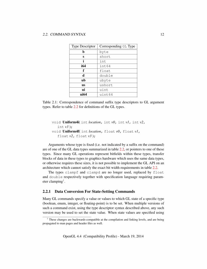
Type Descriptor Corresponding GL Typeb bytes shorti int
i64 int64f floatd double
ub ubyteus ushortui uint
ui64 uint64
Table 2.1: Correspondence of command suffix type descriptors to GL argumenttypes. Refer to table 2.2 for definitions of the GL types.
void Uniform4i( int location, int v0, int v1, int v2,int v3 );
void Uniform4f( int location, float v0, float v1,float v2, float v3 );
Arguments whose type is fixed (i.e. not indicated by a suffix on the command)are of one of the GL data types summarized in table 2.2, or pointers to one of thesetypes. Since many GL operations represent bitfields within these types, transferblocks of data in these types to graphics hardware which uses the same data types,or otherwise requires these sizes, it is not possible to implement the GL API on anarchitecture which cannot satisfy the exact bit width requirements in table 2.2.
The types clampf and clampd are no longer used, replaced by floatand double respectively together with specification language requiring param-eter clamping1.
2.2.1 Data Conversion For State-Setting Commands
Many GL commands specify a value or values to which GL state of a specific type(boolean, enum, integer, or floating-point) is to be set. When multiple versions ofsuch a command exist, using the type descriptor syntax described above, any suchversion may be used to set the state value. When state values are specified using
1 These changes are backwards-compatible at the compilation and linking levels, and are beingpropagated to man pages and header files as well.
OpenGL 4.4 (Compatibility Profile) - March 19, 2014
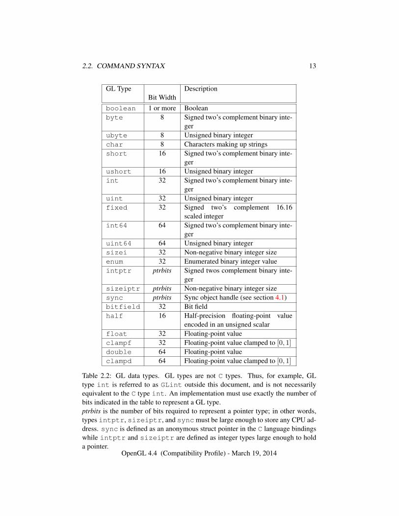
2.2. COMMAND SYNTAX 13
GL Type DescriptionBit Width
boolean 1 or more Booleanbyte 8 Signed two’s complement binary inte-
gerubyte 8 Unsigned binary integerchar 8 Characters making up stringsshort 16 Signed two’s complement binary inte-
gerushort 16 Unsigned binary integerint 32 Signed two’s complement binary inte-
geruint 32 Unsigned binary integerfixed 32 Signed two’s complement 16.16
scaled integerint64 64 Signed two’s complement binary inte-
geruint64 64 Unsigned binary integersizei 32 Non-negative binary integer sizeenum 32 Enumerated binary integer valueintptr ptrbits Signed twos complement binary inte-
gersizeiptr ptrbits Non-negative binary integer sizesync ptrbits Sync object handle (see section 4.1)bitfield 32 Bit fieldhalf 16 Half-precision floating-point value
encoded in an unsigned scalarfloat 32 Floating-point valueclampf 32 Floating-point value clamped to [0, 1]
double 64 Floating-point valueclampd 64 Floating-point value clamped to [0, 1]
Table 2.2: GL data types. GL types are not C types. Thus, for example, GLtype int is referred to as GLint outside this document, and is not necessarilyequivalent to the C type int. An implementation must use exactly the number ofbits indicated in the table to represent a GL type.ptrbits is the number of bits required to represent a pointer type; in other words,types intptr, sizeiptr, and sync must be large enough to store any CPU ad-dress. sync is defined as an anonymous struct pointer in the C language bindingswhile intptr and sizeiptr are defined as integer types large enough to holda pointer.
OpenGL 4.4 (Compatibility Profile) - March 19, 2014
2.2. COMMAND SYNTAX 14
a different parameter type than the actual type of that state, data conversions areperformed as follows:
• When the type of internal state is boolean, zero integer or floating-point val-ues are converted to FALSE and non-zero values are converted to TRUE.
• When the type of internal state is integer or enum, boolean values of FALSEand TRUE are converted to 0 and 1, respectively. Floating-point values arerounded to the nearest integer. If the resulting value is so large in magnitudethat it cannot be represented by the internal state variable, the internal statevalue is undefined.
• When the type of internal state is floating-point, boolean values of FALSEand TRUE are converted to 0.0 and 1.0, respectively. Integer values are con-verted to floating-point, with or without normalization as described for spe-cific commands.
For commands taking arrays of the specified type, these conversions are per-formed for each element of the passed array.
Each command following these conversion rules refers back to this section.Some commands have additional conversion rules specific to certain state valuesand data types, which are described following the reference.
Validation of values performed by state-setting commands is performed afterconversion, unless specified otherwise for a specific command.
2.2.2 Data Conversions For State Query Commands
Query commands (commands whose name begins with Get) return a value or val-ues to which GL state has been set. Some of these commands exist in multipleversions returning different data types. When a query command is issued that re-turns data types different from the actual type of that state, data conversions areperformed as follows:
• If a command returning boolean data is called, such as GetBooleanv, afloating-point or integer value converts to FALSE if and only if it is zero.Otherwise it converts to TRUE.
• If a command returning integer data is called, such as GetIntegerv or Get-Integer64v, a boolean value of TRUE or FALSE is interpreted as one or zero,respectively. A floating-point value is rounded to the nearest integer, unlessthe value is an RGBA color component, a normal coordinate, a DepthRange
OpenGL 4.4 (Compatibility Profile) - March 19, 2014
2.3. COMMAND EXECUTION 15
value, or a depth buffer clear value. In these cases, the query command con-verts the floating-point value to an integer according to the INT entry oftable 18.2; a value not in [−1, 1] converts to an undefined value.
• If a command returning floating-point data is called, such as GetFloatv orGetDoublev, a boolean value of TRUE or FALSE is interpreted as 1.0 or0.0, respectively. An integer value is coerced to floating-point. Single- anddouble-precision floating-point values are converted as necessary.
If a value is so large in magnitude that it cannot be represented by the returneddata type, then the nearest value representable using the requested type is returned.
When querying bitmasks (such as SAMPLE_MASK_VALUE or STENCIL_-
WRITEMASK) with GetIntegerv, the mask value is treated as a signed integer, sothat mask values with the high bit set will not be clamped when returned as signedintegers.
Unless otherwise indicated, multi-valued state variables return their multiplevalues in the same order as they are given as arguments to the commands that setthem. For instance, the two DepthRange parameters are returned in the order nfollowed by f. Similarly, points for evaluator maps are returned in the order thatthey appeared when passed to Map1. Map2 returns Rij in the [(uorder)i + j]thblock of values (see page 624 for i, j, uorder, and Rij).
2.3 Command Execution
Most of the Specification discusses the behavior of a single context bound to asingle CPU thread. It is also possible for multiple contexts to share GL objectsand for each such context to be bound to a different thread. This section introducesconcepts related to GL command execution including error reporting, commandqueue flushing, and synchronization between command streams. Using these toolscan increase performance and utilization of the GPU by separating loosely relatedtasks into different contexts.
Methods to create, manage, and destroy CPU threads are defined by the hostCPU operating system and are not described in the Specification. Binding of GLcontexts to CPU threads is controlled through a window system binding layer suchas those described in section 1.3.5.
2.3.1 Errors
The GL detects only a subset of those conditions that could be considered errors.This is because in many cases error checking would adversely impact the perfor-mance of an error-free program.
OpenGL 4.4 (Compatibility Profile) - March 19, 2014
2.3. COMMAND EXECUTION 16
The command
enum GetError( void );
is used to obtain error information. Each detectable error is assigned a numericcode. When an error is detected, a flag is set and the code is recorded. Furthererrors, if they occur, do not affect this recorded code. When GetError is called,the code is returned and the flag is cleared, so that a further error will again recordits code. If a call to GetError returns NO_ERROR, then there has been no detectableerror since the last call to GetError (or since the GL was initialized).
To allow for distributed implementations, there may be several flag-code pairs.In this case, after a call to GetError returns a value other than NO_ERROR eachsubsequent call returns the non-zero code of a distinct flag-code pair (in unspecifiedorder), until all non-NO_ERROR codes have been returned. When there are no morenon-NO_ERROR error codes, all flags are reset. This scheme requires some positivenumber of pairs of a flag bit and an integer. The initial state of all flags is clearedand the initial value of all codes is NO_ERROR.
Table 2.3 summarizes GL errors. Currently, when an error flag is set, resultsof GL operation are undefined only if an OUT_OF_MEMORY error has occurred. Inother cases, there are no side effects unless otherwise noted; the command whichgenerates the error is ignored so that it has no effect on GL state or framebuffercontents. Except as otherwise noted, if the generating command returns a value, itreturns zero. If the generating command modifies values through a pointer argu-ment, no change is made to these values.
These error semantics apply only to GL errors, not to system errors such asmemory access errors. This behavior is the current behavior; the action of theGL in the presence of errors is subject to change, and extensions to OpenGL maydefine behavior currently considered as an error.
Several error generation conditions are implicit in the description of every GLcommand.
• If a command that requires an enumerated value is passed a symbolic con-stant that is not one of those specified as allowable for that command, anINVALID_ENUM error is generated. This is the case even if the argument isa pointer to a symbolic constant, if the value or values pointed to are notallowable for the given command.
• If a negative number is provided where an argument of type sizei orsizeiptr is specified, an INVALID_VALUE error is generated.
• If memory is exhausted as a side effect of the execution of a command, anOUT_OF_MEMORY error may be generated.
OpenGL 4.4 (Compatibility Profile) - March 19, 2014
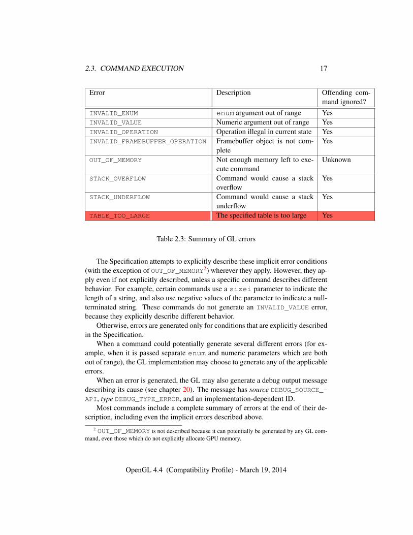
2.3. COMMAND EXECUTION 17
Error Description Offending com-mand ignored?
INVALID_ENUM enum argument out of range YesINVALID_VALUE Numeric argument out of range YesINVALID_OPERATION Operation illegal in current state YesINVALID_FRAMEBUFFER_OPERATION Framebuffer object is not com-
pleteYes
OUT_OF_MEMORY Not enough memory left to exe-cute command
Unknown
STACK_OVERFLOW Command would cause a stackoverflow
Yes
STACK_UNDERFLOW Command would cause a stackunderflow
Yes
TABLE_TOO_LARGE The specified table is too large Yes
Table 2.3: Summary of GL errors
The Specification attempts to explicitly describe these implicit error conditions(with the exception of OUT_OF_MEMORY2) wherever they apply. However, they ap-ply even if not explicitly described, unless a specific command describes differentbehavior. For example, certain commands use a sizei parameter to indicate thelength of a string, and also use negative values of the parameter to indicate a null-terminated string. These commands do not generate an INVALID_VALUE error,because they explicitly describe different behavior.
Otherwise, errors are generated only for conditions that are explicitly describedin the Specification.
When a command could potentially generate several different errors (for ex-ample, when it is passed separate enum and numeric parameters which are bothout of range), the GL implementation may choose to generate any of the applicableerrors.
When an error is generated, the GL may also generate a debug output messagedescribing its cause (see chapter 20). The message has source DEBUG_SOURCE_-API, type DEBUG_TYPE_ERROR, and an implementation-dependent ID.
Most commands include a complete summary of errors at the end of their de-scription, including even the implicit errors described above.
2 OUT_OF_MEMORY is not described because it can potentially be generated by any GL com-mand, even those which do not explicitly allocate GPU memory.
OpenGL 4.4 (Compatibility Profile) - March 19, 2014
2.3. COMMAND EXECUTION 18
Such error summaries are set in a distinct style, like this sentence.
In some cases, however, errors may be generated for a single command forreasons not directly related to that command. One such example is that deferredprocessing for shader programs may result in link errors detected only when at-tempting to draw primitives using vertex specification commands. In such cases,errors generated by a command may be described elsewhere in the specificationthan the command itself.
2.3.2 Flush and Finish
Implementations may buffer multiple commands in a command queue before send-ing them to the GL server for execution. This may happen in places such as thenetwork stack (for network transparent implementations), CPU code executing aspart of the GL client or the GL server, or internally to the GPU hardware. Coarsecontrol over command queues is available using the command
void Flush( void );
which causes all previously issued GL commands to complete in finite time (al-though such commands may still be executing when Flush returns).
The command
void Finish( void );
forces all previously issued GL commands to complete. Finish does not returnuntil all effects from such commands on GL client and server state and the frame-buffer are fully realized.
Finer control over command execution can be expressed using fence commandsand sync objects, as discussed in section 4.1.
2.3.3 Numeric Representation and Computation
The GL must perform a number of floating-point operations during the course ofits operation.
Implementations normally perform computations in floating-point, and mustmeet the range and precision requirements defined under ”Floating-Point Com-putation” below.
These requirements only apply to computations performed in GL operationsoutside of shader execution, such as texture image specification and sampling, and
OpenGL 4.4 (Compatibility Profile) - March 19, 2014
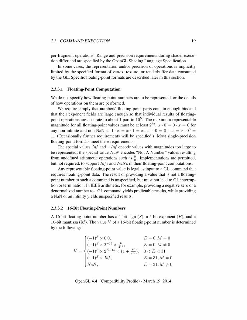
2.3. COMMAND EXECUTION 19
per-fragment operations. Range and precision requirements during shader execu-tion differ and are specified by the OpenGL Shading Language Specification.
In some cases, the representation and/or precision of operations is implicitlylimited by the specified format of vertex, texture, or renderbuffer data consumedby the GL. Specific floating-point formats are described later in this section.
2.3.3.1 Floating-Point Computation
We do not specify how floating-point numbers are to be represented, or the detailsof how operations on them are performed.
We require simply that numbers’ floating-point parts contain enough bits andthat their exponent fields are large enough so that individual results of floating-point operations are accurate to about 1 part in 105. The maximum representablemagnitude for all floating-point values must be at least 232. x · 0 = 0 · x = 0 forany non-infinite and non-NaN x. 1 · x = x · 1 = x. x + 0 = 0 + x = x. 00 =1. (Occasionally further requirements will be specified.) Most single-precisionfloating-point formats meet these requirements.
The special values Inf and −Inf encode values with magnitudes too large tobe represented; the special value NaN encodes “Not A Number” values resultingfrom undefined arithmetic operations such as 0
0 . Implementations are permitted,but not required, to support Inf s and NaN s in their floating-point computations.
Any representable floating-point value is legal as input to a GL command thatrequires floating-point data. The result of providing a value that is not a floating-point number to such a command is unspecified, but must not lead to GL interrup-tion or termination. In IEEE arithmetic, for example, providing a negative zero or adenormalized number to a GL command yields predictable results, while providinga NaN or an infinity yields unspecified results.
2.3.3.2 16-Bit Floating-Point Numbers
A 16-bit floating-point number has a 1-bit sign (S), a 5-bit exponent (E), and a10-bit mantissa (M ). The value V of a 16-bit floating-point number is determinedby the following:
V =
(−1)S × 0.0, E = 0,M = 0
(−1)S × 2−14 × M210, E = 0,M 6= 0
(−1)S × 2E−15 ×(1 + M
210
), 0 < E < 31
(−1)S × Inf , E = 31,M = 0
NaN , E = 31,M 6= 0
OpenGL 4.4 (Compatibility Profile) - March 19, 2014
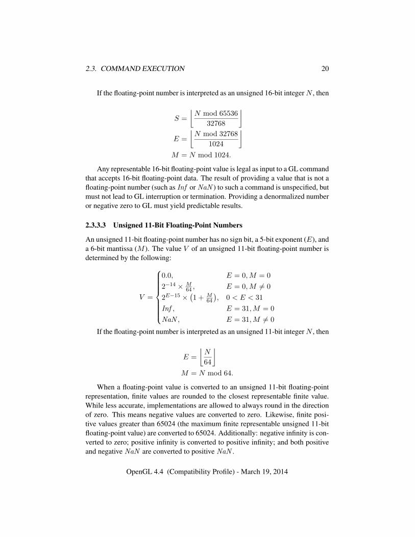
2.3. COMMAND EXECUTION 20
If the floating-point number is interpreted as an unsigned 16-bit integerN , then
S =
⌊N mod 65536
32768
⌋E =
⌊N mod 32768
1024
⌋M = N mod 1024.
Any representable 16-bit floating-point value is legal as input to a GL commandthat accepts 16-bit floating-point data. The result of providing a value that is not afloating-point number (such as Inf or NaN ) to such a command is unspecified, butmust not lead to GL interruption or termination. Providing a denormalized numberor negative zero to GL must yield predictable results.
2.3.3.3 Unsigned 11-Bit Floating-Point Numbers
An unsigned 11-bit floating-point number has no sign bit, a 5-bit exponent (E), anda 6-bit mantissa (M ). The value V of an unsigned 11-bit floating-point number isdetermined by the following:
V =
0.0, E = 0,M = 0
2−14 × M64 , E = 0,M 6= 0
2E−15 ×(1 + M
64
), 0 < E < 31
Inf , E = 31,M = 0
NaN , E = 31,M 6= 0
If the floating-point number is interpreted as an unsigned 11-bit integerN , then
E =
⌊N
64
⌋M = N mod 64.
When a floating-point value is converted to an unsigned 11-bit floating-pointrepresentation, finite values are rounded to the closest representable finite value.While less accurate, implementations are allowed to always round in the directionof zero. This means negative values are converted to zero. Likewise, finite posi-tive values greater than 65024 (the maximum finite representable unsigned 11-bitfloating-point value) are converted to 65024. Additionally: negative infinity is con-verted to zero; positive infinity is converted to positive infinity; and both positiveand negative NaN are converted to positive NaN .
OpenGL 4.4 (Compatibility Profile) - March 19, 2014
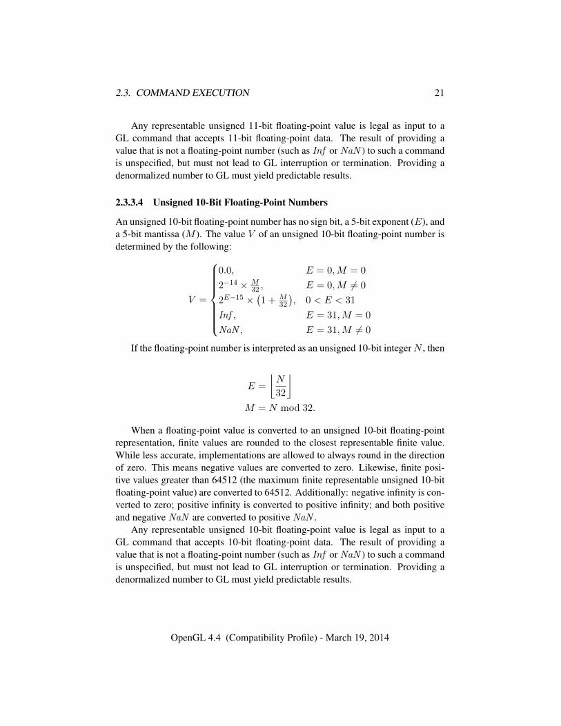
2.3. COMMAND EXECUTION 21
Any representable unsigned 11-bit floating-point value is legal as input to aGL command that accepts 11-bit floating-point data. The result of providing avalue that is not a floating-point number (such as Inf or NaN ) to such a commandis unspecified, but must not lead to GL interruption or termination. Providing adenormalized number to GL must yield predictable results.
2.3.3.4 Unsigned 10-Bit Floating-Point Numbers
An unsigned 10-bit floating-point number has no sign bit, a 5-bit exponent (E), anda 5-bit mantissa (M ). The value V of an unsigned 10-bit floating-point number isdetermined by the following:
V =
0.0, E = 0,M = 0
2−14 × M32 , E = 0,M 6= 0
2E−15 ×(1 + M
32
), 0 < E < 31
Inf , E = 31,M = 0
NaN , E = 31,M 6= 0
If the floating-point number is interpreted as an unsigned 10-bit integerN , then
E =
⌊N
32
⌋M = N mod 32.
When a floating-point value is converted to an unsigned 10-bit floating-pointrepresentation, finite values are rounded to the closest representable finite value.While less accurate, implementations are allowed to always round in the directionof zero. This means negative values are converted to zero. Likewise, finite posi-tive values greater than 64512 (the maximum finite representable unsigned 10-bitfloating-point value) are converted to 64512. Additionally: negative infinity is con-verted to zero; positive infinity is converted to positive infinity; and both positiveand negative NaN are converted to positive NaN .
Any representable unsigned 10-bit floating-point value is legal as input to aGL command that accepts 10-bit floating-point data. The result of providing avalue that is not a floating-point number (such as Inf or NaN ) to such a commandis unspecified, but must not lead to GL interruption or termination. Providing adenormalized number to GL must yield predictable results.
OpenGL 4.4 (Compatibility Profile) - March 19, 2014
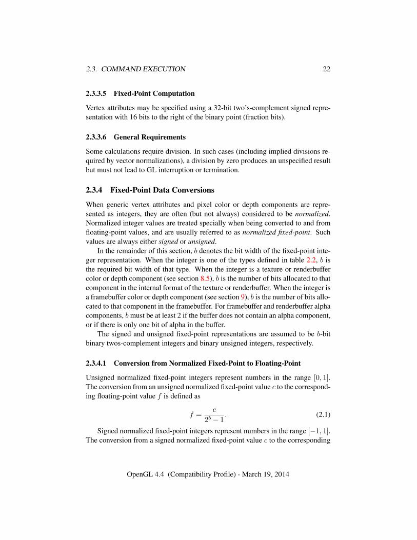
2.3. COMMAND EXECUTION 22
2.3.3.5 Fixed-Point Computation
Vertex attributes may be specified using a 32-bit two’s-complement signed repre-sentation with 16 bits to the right of the binary point (fraction bits).
2.3.3.6 General Requirements
Some calculations require division. In such cases (including implied divisions re-quired by vector normalizations), a division by zero produces an unspecified resultbut must not lead to GL interruption or termination.
2.3.4 Fixed-Point Data Conversions
When generic vertex attributes and pixel color or depth components are repre-sented as integers, they are often (but not always) considered to be normalized.Normalized integer values are treated specially when being converted to and fromfloating-point values, and are usually referred to as normalized fixed-point. Suchvalues are always either signed or unsigned.
In the remainder of this section, b denotes the bit width of the fixed-point inte-ger representation. When the integer is one of the types defined in table 2.2, b isthe required bit width of that type. When the integer is a texture or renderbuffercolor or depth component (see section 8.5), b is the number of bits allocated to thatcomponent in the internal format of the texture or renderbuffer. When the integer isa framebuffer color or depth component (see section 9), b is the number of bits allo-cated to that component in the framebuffer. For framebuffer and renderbuffer alphacomponents, bmust be at least 2 if the buffer does not contain an alpha component,or if there is only one bit of alpha in the buffer.
The signed and unsigned fixed-point representations are assumed to be b-bitbinary twos-complement integers and binary unsigned integers, respectively.
2.3.4.1 Conversion from Normalized Fixed-Point to Floating-Point
Unsigned normalized fixed-point integers represent numbers in the range [0, 1].The conversion from an unsigned normalized fixed-point value c to the correspond-ing floating-point value f is defined as
f =c
2b − 1. (2.1)
Signed normalized fixed-point integers represent numbers in the range [−1, 1].The conversion from a signed normalized fixed-point value c to the corresponding
OpenGL 4.4 (Compatibility Profile) - March 19, 2014
2.3. COMMAND EXECUTION 23
floating-point value f is performed using
f = max
{c
2b−1 − 1,−1.0
}. (2.2)
Only the range [−2b−1 + 1, 2b−1 − 1] is used to represent signed fixed-pointvalues in the range [−1, 1]. For example, if b = 8, then the integer value−127 cor-responds to−1.0 and the value 127 corresponds to 1.0. Note that while zero can beexactly expressed in this representation, one value (−128 in the example) is outsidethe representable range, and must be clamped before use. This equation is used ev-erywhere that signed normalized fixed-point values are converted to floating-point,including for all signed normalized fixed-point parameters in GL commands, suchas vertex attribute values3, as well as for specifying texture or framebuffer valuesusing signed normalized fixed-point.
2.3.4.2 Conversion from Floating-Point to Normalized Fixed-Point
The conversion from a floating-point value f to the corresponding unsigned nor-malized fixed-point value c is defined by first clamping f to the range [0, 1], thencomputing
f ′ = f × (2b − 1). (2.3)
f ′ is then cast to an unsigned binary integer value with exactly b bits.The conversion from a floating-point value f to the corresponding signed nor-
malized fixed-point value c is performed by clamping f to the range [−1, 1], thencomputing
f ′ = f × (2b−1 − 1). (2.4)
After conversion, f ′ is then cast to a signed two’s-complement binary integervalue with exactly b bits.
This equation is used everywhere that floating-point values are converted tosigned normalized fixed-point, including when querying floating-point state (seesection 2.2.2) and returning integers4, as well as for specifying signed normalizedtexture or framebuffer values using floating-point.
3 This is a behavior change in OpenGL 4.2. In previous versions, a different conversion for signednormalized values was used in which −128 mapped to −1.0, 127 mapped to 1.0, and 0.0 was notexactly representable.
4 This is a behavior change in OpenGL 4.2. In previous versions, a different conversion for signednormalized values was used in which −1.0 mapped to −128, 1.0 mapped to 127, and 0.0 was notexactly representable.
OpenGL 4.4 (Compatibility Profile) - March 19, 2014
2.4. RENDERING COMMANDS 24
2.4 Rendering Commands
GL commands performing rendering into a framebuffer are sometimes treated spe-cially by other GL operations such as conditional rendering (see section 10.10).Such commands are called rendering commands, and include the drawing com-mands *Draw* (see section 10.5) and Begin / End (see section 10.8), as well asthese additional commands:
• Accum (see section 17.4.5)
• Bitmap (see section 14.8)
• BlitFramebuffer (see section 18.3.2)
• Clear (see section 17.4.3)
• ClearBuffer* (see section 17.4.3.1)
• CopyPixels (see section 18.3)
• DispatchCompute* (see section 19)
• DrawPixels (see section 18.1)
• EvalMesh1 and EvalMesh2 (see section 21.1)
2.5 Context State
Context state is state that belongs to the GL context as a whole, rather than toinstances of the different object types described in section 2.6. Context state con-trols fixed-function stages of the GPU, such as clipping, primitive rasterization, andframebuffer clears, and also specifies bindings of objects to the context specifyingwhich objects are used during command execution.
Context state also controls the fixed-function stages described as legacy alter-natives to shaders for performing transformation, lighting, and texturing.
The Specification describes all visible context state variables and describes howeach one can be changed. State variables are grouped somewhat arbitrarily by theirfunction. Although we describe operations that the GL performs on the frame-buffer, the framebuffer is not a part of GL state.
There are two types of context state. Server state resides in the GL server;the majority of GL state falls into this category. Client state resides in the GLclient. Unless otherwise specified, all state is server state; client state is specifically
OpenGL 4.4 (Compatibility Profile) - March 19, 2014
2.6. OBJECTS AND THE OBJECT MODEL 25
identified. Each instance of a context includes a complete set of server state; eachconnection from a client to a server also includes a complete set of client state.
While an implementation of OpenGL may be hardware dependent, the Specifi-cation is independent of any specific hardware on which it is implemented. We areconcerned with the state of graphics hardware only when it corresponds preciselyto GL state.
2.5.1 Generic Context State Queries
Context state queries are described in detail in chapter 22.
2.6 Objects and the Object Model
Many types of objects are defined in the remainder of the Specification. Applica-tions may create, modify, query, and destroy many instances of each of these objecttypes, limited in most cases only by available graphics memory. Specific instancesof different object types are bound to a context. The set of bound objects definethe shaders which are invoked by GL drawing operations; specify the buffer data,texture image, and framebuffer memory that is accessed by shaders and directlyby GL commands; and contain the state used by other operations such as fencesynchronization and timer queries.
Each object type corresponds to a distinct set of commands which manage ob-jects of that type. However, there is an object model describing how most typesof objects are managed, described below. Exceptions to the object model for spe-cific object types are described later in the Specification together with those objecttypes.
Following the description of the object model, each type of object is brieflydescribed below, together with forward references to full descriptions of that ob-ject type in later chapters of the Specification. Objects are described in an ordercorresponding to the structure of the remainder of the Specification.
2.6.1 Object Management
2.6.1.1 Name Spaces, Name Generation, and Object Creation
Each object type has a corresponding name space. Names of objects are repre-sented by unsigned integers of type uint. The name zero is reserved by the GL;for some object types, zero names a default object of that type, and in others zerowill never correspond to an actual instance of that object type.
OpenGL 4.4 (Compatibility Profile) - March 19, 2014
2.6. OBJECTS AND THE OBJECT MODEL 26
Names of most types of objects are created by generating unused names us-ing commands starting with Gen followed by the object type. For example, thecommand GenBuffers returns one or more previously unused buffer object names.
Generated names are marked by the GL as used, for the purpose of name gener-ation only. Object names marked in this fashion will not be returned by additionalcalls to generate names of the same type until the names are marked unused againby deleting them (see below).
Generated names do not initially correspond to an instance of an object. Ob-jects with generated names are created by binding a generated name to the context.For example, a buffer object is created by calling the command BindBuffer witha name returned by GenBuffers, which allocates resources for the buffer objectand its state, and associate the name with that object. Sampler objects may also becreated by commands in addition to BindSampler, as described in section 8.2.
A few types of objects are created by commands which return the name of thenew object at the same time they create the object. Examples include CreatePro-gram for program objects and FenceSync for fence sync objects.
2.6.1.2 Name Deletion and Object Deletion
Objects are deleted by calling deletion commands specific to that object type. Forexample, the command DeleteBuffers is passed an array of buffer object namesto delete. After an object is deleted it has no contents, and its name is once againmarked unused for the purpose of name generation. If names are deleted that do notcorrespond to an object, but have been marked for the purpose of name generation,such names are marked as unused again. If unused and unmarked names are deletedthey are silently ignored, as is the name zero.
If an object is deleted while it is currently in use by a GL context, its nameis immediately marked as unused, and some types of objects are automaticallyunbound from binding points in the current context, as described in section 5.1.2.However, the actual underlying object is not deleted until it is no longer in use.This situation is discussed in more detail in section 5.1.3.
2.6.1.3 Shared Object State
It is possible for groups of contexts to share some server state. Enabling such shar-ing between contexts is done through window system binding APIs such as thosedescribed in section 1.3.5. These APIs are responsible for creation and manage-ment of contexts, and are not discussed further here. More detailed discussion ofthe behavior of shared objects is included in chapter 5. Except as defined belowfor specific object types, all state in a context is specific to that context only.
OpenGL 4.4 (Compatibility Profile) - March 19, 2014
2.6. OBJECTS AND THE OBJECT MODEL 27
2.6.2 Buffer Objects
The GL uses many types of data supplied by the client. Some of this data must bestored in server memory, and it is desirable to store other types of frequently usedclient data, such as vertex array and pixel data, in server memory for performancereasons, even if the option to store it in client memory exists.
Buffer objects contain a data store holding a fixed-sized allocation of servermemory, and provide a mechanism to allocate, initialize, read from, and write tosuch memory. Under certain circumstances, the data store of a buffer object maybe shared between the client and server and accessed simultaneously by both.
Buffer objects may be shared. They are described in detail in chapter 6.
2.6.3 Shader Objects
The source and/or binary code representing part or all of a shader program that isexecuted by one of the programmable stages defined by the GL (such as a vertexor fragment shader) is encapsulated in one or more shader objects.
Shader objects may be shared. They are described in detail in chapter 7.
2.6.4 Program Objects
Shader objects that are to be used by one or more of the programmable stages ofthe GL are linked together to form a program object. The shader programs thatare executed by these programmable stages are called executables. All informationnecessary for defining each executable is encapsulated in a program object.
Program objects may be shared. They are described in detail in chapter 7.
2.6.5 Program Pipeline Objects
Program pipeline objects contain a separate program object binding point for eachprogrammable stage. They allow a primitive to be processed by independent pro-grams in each programmable stage, instead of requiring a single program objectfor each combination of shader operations. They allow greater flexibility whencombining different shaders in various ways, without requiring a program objectfor each such combination.
Program pipeline objects are container objects including references to programobjects, and are not shared. They are described in detail in chapter 7.
2.6.6 Texture Objects
Texture objects or textures include a collection of texture images built from arrays
OpenGL 4.4 (Compatibility Profile) - March 19, 2014
2.6. OBJECTS AND THE OBJECT MODEL 28
of image elements referred to as texels. There are many types of texture objectsvarying by dimensionality and structure; the different texture types are describedin detail in the introduction to chapter 8.
Texture objects also include state describing the image parameters of the tex-ture images, and state describing how sampling is performed when a shader ac-cesses a texture.
Shaders may sample a texture at a location indicated by specified texture co-ordinates, with details of sampling determined by the sampler state of the texture.The resulting texture samples are typically used to modify a fragment’s color, inorder to map an image onto a geometric primitive being drawn, but may be usedfor any purpose in a shader.
Texture objects may be shared. They are described in detail in chapter 8.
2.6.7 Sampler Objects
Sampler objects contain the subset of texture object state controlling how samplingis performed when a shader accesses a texture. Sampler and texture objects may bebound together so that the sampler object state is used by shaders when samplingthe texture, overriding equivalent state in the texture object. Separating textureimage data from the method of sampling that data allows reuse of the same samplerstate with many different textures without needing to set the sampler state in eachtexture.
Sampler objects may be shared. They are described in detail in chapter 8.
2.6.8 Renderbuffer Objects
Renderbuffer objects contain a single image in a format which can be renderedto. Renderbuffer objects are attached to framebuffer objects (see below) whenperforming off-screen rendering.
Renderbuffer objects may be shared. They are described in detail in chapter 9.
2.6.9 Framebuffer Objects
Framebuffer objects encapsulate the state of a framebuffer, including a collection ofcolor, depth, and stencil buffers. Each such buffer is represented by a renderbufferobject or texture object attached to the framebuffer object.
Framebuffer objects are container objects including references to renderbuffer
OpenGL 4.4 (Compatibility Profile) - March 19, 2014
2.6. OBJECTS AND THE OBJECT MODEL 29
and/or texture objects, and are not shared5. They are described in detail in chap-ter 9.
2.6.10 Vertex Array Objects
Vertex array objects represent a collection of sets of vertex attributes. Each setis stored as an array in a buffer object data store, with each element of the arrayhaving a specified format and component count. The attributes of the currentlybound vertex array object are used as inputs to the vertex shader when executingdrawing commands.
Vertex array objects are container objects including references to buffer objects,and are not shared. They are described in detail in chapter 10.
2.6.11 Transform Feedback Objects
Transform feedback objects are used to capture attributes of the vertices of trans-formed primitives passed to the transform feedback stage when transform feedbackmode is active. They include state required for transform feedback together withreferences to buffer objects in which attributes are captured.
Transform feedback objects are container objects including references to bufferobjects, and are not shared. They are described in detail in section 13.2.1.
2.6.12 Query Objects
Query objects return information about the processing of a sequence of GL com-mands, such as the number of primitives processed by drawing commands; thenumber of primitives written to transform feedback buffers; the number of sam-ples that pass the depth test during fragment processing; and the amount of timerequired to process commands.
Query objects are not shared. They are described in detail in section 4.2.
2.6.13 Sync Objects
A sync object acts as a synchronization primitive – a representation of events whosecompletion status can be tested or waited upon. Sync objects may be used for syn-chronization with operations occurring in the GL state machine or in the graphics
5 Framebuffer objects created with the commands defined by the GL_EXT_-framebuffer_object extension are defined to be shared, while FBOs created withcommands defined by the OpenGL core or GL_ARB_framebuffer_object extension aredefined to not be shared. Undefined behavior results when using FBOs created by EXT commandsthrough non-EXT interfaces, or vice-versa.
OpenGL 4.4 (Compatibility Profile) - March 19, 2014
2.6. OBJECTS AND THE OBJECT MODEL 30
pipeline, and for synchronizing between multiple graphics contexts, among otherpurposes.
Sync objects may be shared. They are described in detail in section 4.1.
2.6.14 Display Lists
A display list is an object representing a group of GL commands and their parame-ters which have been stored in server memory for subsequent execution. This maybe desirable for performance reasons when the GL client and server are separatedby a network, or when the CPU to GPU interface is too slow to keep the GPU fullyfed. Most of the benefits of display lists can be more easily achieved in moderngraphics architectures by storing as much data as possible in GL objects in servermemory, and display lists have been deprecated.
Display lists may be shared. They are described in detail in chapter 21.4.
OpenGL 4.4 (Compatibility Profile) - March 19, 2014
Chapter 3
Dataflow Model
Figure 3.1 shows a block diagram of the GL. Some commands specify geometricobjects to be drawn while others specify state controlling how objects are han-dled by the various stages, or specify data contained in textures and buffer objects.Most commands may be accumulated in a display list for processing by the GLat a later time. Otherwise, commands are effectively sent through a processingpipeline. Different stages of the pipeline use data contained in different types ofbuffer objects. Some pipeline stages may use data in client memory instead of, orin addition to data in buffer objects. Data in client memory are not shown in theblock diagram, but are described later in the specification as part of the descriptionof those pipeline stages.
The first stage assembles vertices to form geometric primitives such as points,line segments, and polygons. In the next stage vertices may be transformed and lit,followed by assembly into geometric primitives. Tessellation and geometry shadersmay then generate multiple primitives from single input primitives. Optionally, theresults of these pipeline stages may be fed back into buffer objects using transformfeedback.
The final resulting primitives are clipped to a clip volume in preparation for thenext stage, rasterization. The rasterizer produces a series of framebuffer addressesand values using a two-dimensional description of a point, line segment, or poly-gon. Each fragment so produced is fed to the next stage that performs operationson individual fragments before they finally alter the framebuffer. These operationsinclude conditional updates into the framebuffer based on incoming and previouslystored depth values (to effect depth buffering), blending of incoming fragment col-ors with stored colors, as well as masking, stenciling, and other logical operationson fragment values.
There is a way to bypass the vertex processing portion of the pipeline to send a
31
32
block of fragments directly to the individual fragment operations, eventually caus-ing a block of pixels to be written to the framebuffer, and pixels may also beread back from the framebuffer or copied from one portion of the framebuffer toanother. These transfers may include some type of decoding or encoding.
Some additional stages are not shown in figure 3.1. One such stage computesvertices by evaluating polynomial functions of input values, providing an efficientmeans for approximating curve and surface geometry rather than specifying eachvertex explicitly. Another operates on pixel data in the process of reading from orwriting to the framebuffer or texture images.
Finally, compute shaders which may read from and write to buffer objects maybe executed independently of the pipeline shown in figure 3.1.
This ordering is meant only as a tool for describing the GL, not as a strict ruleof how the GL is implemented, and we present it only as a means to organize thevarious operations of the GL. Objects such as curved surfaces, for instance, maybe transformed before they are converted to polygons.
OpenGL 4.4 (Compatibility Profile) - March 19, 2014
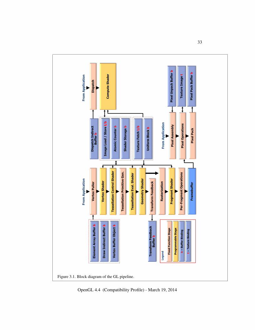
33
Fra
me
bu
ffe
r
Ve
rte
x P
ull
er
Ve
rte
x S
ha
de
r
Te
sse
lla
tio
n C
on
tro
l S
ha
de
r
Te
sse
lla
tio
n P
rim
itiv
e G
en
.
Ge
om
etr
y S
ha
de
r
Tra
nsfo
rm F
ee
db
ack
Ra
ste
riza
tio
n
Fra
gm
en
t S
ha
de
r
Dis
pa
tch
In
dir
ect
Bu
ffe
r b
Pix
el A
sse
mb
ly
Pix
el O
pe
rati
on
s
Pix
el P
ack
Pe
r-Fra
gm
en
t O
pe
rati
on
s
Im
ag
e L
oa
d /
Sto
re t
/b
Ato
mic
Co
un
ter
b
Sh
ad
er
Sto
rag
e b
Te
xtu
re F
etc
h t
/b
Un
ifo
rm B
lock
b
Pix
el U
np
ack
Bu
ffe
r b
Te
xtu
re I
ma
ge
t
Pix
el P
ack
Bu
ffe
r b
Ele
me
nt
Arr
ay B
uff
er
b
Dra
w I
nd
ire
ct
Bu
ffe
r b
Ve
rte
x B
uff
er
Ob
ject
b
Tra
nsfo
rm F
ee
db
ack
B
uff
er
b
Fro
m A
pp
lica
tio
n
Fro
m A
pp
lica
tio
n
t –
Te
xtu
re B
ind
ing
b –
Bu
ffe
r B
ind
ing
Pro
gra
mm
ab
le S
tag
e
Fix
ed
Fu
ncti
on
Sta
ge
Te
sse
lla
tio
n E
va
l. S
ha
de
r
Dis
pa
tch
Co
mp
ute
Sh
ad
er
Fro
m A
pp
lica
tio
n
Le
ge
nd
Figure 3.1. Block diagram of the GL pipeline.
OpenGL 4.4 (Compatibility Profile) - March 19, 2014
Chapter 4
Event Model
4.1 Sync Objects and Fences
A sync object acts as a synchronization primitive – a representation of events whosecompletion status can be tested or waited upon. Sync objects may be used for syn-chronization with operations occurring in the GL state machine or in the graphicspipeline, and for synchronizing between multiple graphics contexts, among otherpurposes.
Sync objects have a status value with two possible states: signaled andunsignaled. Events are associated with a sync object. When a sync object is cre-ated, its status is set to unsignaled. When the associated event occurs, the syncobject is signaled (its status is set to signaled). The GL may be asked to wait for async object to become signaled.
Initially, only one specific type of sync object is defined: the fence sync object,whose associated event is triggered by a fence command placed in the GL com-mand stream. Fence sync objects are used to wait for partial completion of the GLcommand stream, as a more flexible form of Finish.
The command
sync FenceSync( enum condition, bitfield flags );
creates a new fence sync object, inserts a fence command in the GL commandstream and associates it with that sync object, and returns a non-zero name corre-sponding to the sync object.
When the specified condition of the sync object is satisfied by the fence com-mand, the sync object is signaled by the GL, causing any ClientWaitSync or Wait-Sync commands (see below) blocking on sync to unblock. No other state is affectedby FenceSync or by execution of the associated fence command.
34
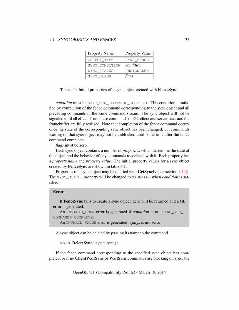
4.1. SYNC OBJECTS AND FENCES 35
Property Name Property ValueOBJECT_TYPE SYNC_FENCE
SYNC_CONDITION conditionSYNC_STATUS UNSIGNALED
SYNC_FLAGS flags
Table 4.1: Initial properties of a sync object created with FenceSync.
condition must be SYNC_GPU_COMMANDS_COMPLETE. This condition is satis-fied by completion of the fence command corresponding to the sync object and allpreceding commands in the same command stream. The sync object will not besignaled until all effects from these commands on GL client and server state and theframebuffer are fully realized. Note that completion of the fence command occursonce the state of the corresponding sync object has been changed, but commandswaiting on that sync object may not be unblocked until some time after the fencecommand completes.
flags must be zero.Each sync object contains a number of properties which determine the state of
the object and the behavior of any commands associated with it. Each property hasa property name and property value. The initial property values for a sync objectcreated by FenceSync are shown in table 4.1.
Properties of a sync object may be queried with GetSynciv (see section 4.1.3).The SYNC_STATUS property will be changed to SIGNALED when condition is sat-isfied.
Errors
If FenceSync fails to create a sync object, zero will be returned and a GLerror is generated.
An INVALID_ENUM error is generated if condition is not SYNC_GPU_-COMMANDS_COMPLETE.
An INVALID_VALUE error is generated if flags is not zero.
A sync object can be deleted by passing its name to the command
void DeleteSync( sync sync );
If the fence command corresponding to the specified sync object has com-pleted, or if no ClientWaitSync or WaitSync commands are blocking on sync, the
OpenGL 4.4 (Compatibility Profile) - March 19, 2014
4.1. SYNC OBJECTS AND FENCES 36
object is deleted immediately. Otherwise, sync is flagged for deletion and will bedeleted when it is no longer associated with any fence command and is no longerblocking any ClientWaitSync or WaitSync command. In either case, after return-ing from DeleteSync the sync name is invalid and can no longer be used to refer tothe sync object.
DeleteSync will silently ignore a sync value of zero.
Errors
An INVALID_VALUE error is generated if sync is neither zero nor the nameof a sync object.
4.1.1 Waiting for Sync Objects
The command
enum ClientWaitSync( sync sync, bitfield flags,uint64 timeout );
causes the GL to block, and will not return until the sync object sync is signaled,or until the specified timeout period expires. timeout is in units of nanoseconds.timeout is adjusted to the closest value allowed by the implementation-dependenttimeout accuracy, which may be substantially longer than one nanosecond, andmay be longer than the requested period.
If sync is signaled at the time ClientWaitSync is called, then ClientWait-Sync returns immediately. If sync is unsignaled at the time ClientWaitSync iscalled, then ClientWaitSync will block and will wait up to timeout nanosecondsfor sync to become signaled. flags controls command flushing behavior, and maybe SYNC_FLUSH_COMMANDS_BIT, as discussed in section 4.1.2.
ClientWaitSync returns one of four status values. A return value ofALREADY_SIGNALED indicates that sync was signaled at the time ClientWait-Sync was called. ALREADY_SIGNALED will always be returned if sync was sig-naled, even if the value of timeout is zero. A return value of TIMEOUT_EXPIREDindicates that the specified timeout period expired before sync was signaled. A re-turn value of CONDITION_SATISFIED indicates that sync was signaled before thetimeout expired. Finally, if an error occurs, in addition to generating a GL erroras specified below, ClientWaitSync immediately returns WAIT_FAILED withoutblocking.
If the value of timeout is zero, then ClientWaitSync does not block, but simplytests the current state of sync. TIMEOUT_EXPIRED will be returned in this case ifsync is not signaled, even though no actual wait was performed.
OpenGL 4.4 (Compatibility Profile) - March 19, 2014
4.1. SYNC OBJECTS AND FENCES 37
Errors
An INVALID_VALUE error is generated if sync is not the name of a syncobject.
An INVALID_VALUE error is generated if flags contains any bits other thanSYNC_FLUSH_COMMANDS_BIT.
The command
void WaitSync( sync sync, bitfield flags,uint64 timeout );
is similar to ClientWaitSync, but instead of blocking and not returning to the ap-plication until sync is signaled, WaitSync returns immediately, instead causing theGL server to block1 until sync is signaled2.
sync has the same meaning as for ClientWaitSync.timeout must currently be the special value TIMEOUT_IGNORED, and is not
used. Instead, WaitSync will always wait no longer than an implementation-dependent timeout. The duration of this timeout in nanoseconds may be queriedby calling GetInteger64v with the symbolic constant MAX_SERVER_WAIT_-
TIMEOUT. There is currently no way to determine whether WaitSync unblockedbecause the timeout expired or because the sync object being waited on was sig-naled.
flags must be zero.If an error occurs, WaitSync generates a GL error as specified below, and does
not cause the GL server to block.
Errors
An INVALID_VALUE error is generated if sync is not the name of a syncobject.
An INVALID_VALUE error is generated if timeout is not TIMEOUT_-IGNORED or flags is not zeroa.
a flags and timeout are placeholders for anticipated future extensions of sync object capa-bilities. They must have these reserved values in order that existing code calling WaitSyncoperate properly in the presence of such extensions.
1 The GL server may choose to wait either in the CPU executing server-side code, or in the GPUhardware if it supports this operation.
2 WaitSync allows applications to continue to queue commands from the client in anticipation ofthe sync being signaled, increasing client-server parallelism.
OpenGL 4.4 (Compatibility Profile) - March 19, 2014
4.1. SYNC OBJECTS AND FENCES 38
4.1.1.1 Multiple Waiters
It is possible for both the GL client to be blocked on a sync object in a ClientWait-Sync command, the GL server to be blocked as the result of a previous WaitSynccommand, and for additional WaitSync commands to be queued in the GL server,all for a single sync object. When such a sync object is signaled in this situation,the client will be unblocked, the server will be unblocked, and all such queuedWaitSync commands will continue immediately when they are reached.
See section 5.2 for more information about blocking on a sync object in multi-ple GL contexts.
4.1.2 Signaling
A fence sync object enters the signaled state only once the corresponding fencecommand has completed and signaled the sync object.
If the sync object being blocked upon will not be signaled in finite time (forexample, by an associated fence command issued previously, but not yet flushedto the graphics pipeline), then ClientWaitSync may hang forever. To help preventthis behavior3, if the SYNC_FLUSH_COMMANDS_BIT bit is set in flags, and sync isunsignaled when ClientWaitSync is called, then the equivalent of Flush will beperformed before blocking on sync.
Additional constraints on the use of sync objects are discussed in chapter 5.State must be maintained to indicate which sync object names are currently
in use. The state required for each sync object in use is an integer for the specifictype, an integer for the condition, and a bit indicating whether the object is signaledor unsignaled. The initial values of sync object state are defined as specified byFenceSync.
4.1.3 Sync Object Queries
Properties of sync objects may be queried using the command
void GetSynciv( sync sync, enum pname, sizei bufSize,sizei *length, int *values );
The value or values being queried are returned in the parameters length andvalues.
3 The simple flushing behavior defined by SYNC_FLUSH_COMMANDS_BIT will not helpwhen waiting for a fence command issued in another context’s command stream to complete. Ap-plications which block on a fence sync object must take additional steps to assure that the contextfrom which the corresponding fence command was issued has flushed that command to the graphicspipeline.
OpenGL 4.4 (Compatibility Profile) - March 19, 2014
4.2. QUERY OBJECTS AND ASYNCHRONOUS QUERIES 39
On success, GetSynciv replaces up to bufSize integers in values with the cor-responding property values of the object being queried. The actual number ofintegers replaced is returned in *length. If length is NULL, no length is returned.
If pname is OBJECT_TYPE, a single value representing the specific type of thesync object is placed in values. The only type supported is SYNC_FENCE.
If pname is SYNC_STATUS, a single value representing the status of the syncobject (SIGNALED or UNSIGNALED) is placed in values.
If pname is SYNC_CONDITION, a single value representing the condition ofthe sync object is placed in values. The only condition supported is SYNC_GPU_-COMMANDS_COMPLETE.
If pname is SYNC_FLAGS, a single value representing the flags with which thesync object was created is placed in values. No flags are currently supported.
Errors
An INVALID_VALUE error is generated if sync is not the name of a syncobject.
An INVALID_ENUM error is generated if pname is not one of the valuesdescribed above.
An INVALID_VALUE error is generated if bufSize is negative.
The command
boolean IsSync( sync sync );
returns TRUE if sync is the name of a sync object. If sync is not the name of a syncobject, or if an error condition occurs, IsSync returns FALSE (note that zero is notthe name of a sync object).
Sync object names immediately become invalid after calling DeleteSync, asdiscussed in sections 4.1 and 5.2, but the underlying sync object will not be deleteduntil it is no longer associated with any fence command and no longer blockingany *WaitSync command.
4.2 Query Objects and Asynchronous Queries
Asynchronous queries provide a mechanism to return information about the pro-cessing of a sequence of GL commands. Query types supported by the GL include
• Primitive queries with a target of PRIMITIVES_GENERATED (see sec-tion 13.3) return information on the number of primitives processed by
OpenGL 4.4 (Compatibility Profile) - March 19, 2014
4.2. QUERY OBJECTS AND ASYNCHRONOUS QUERIES 40
the GL. There may be at most the value of MAX_VERTEX_STREAMS activequeries of this type.
• Primitive queries with a target of TRANSFORM_FEEDBACK_PRIMITIVES_-WRITTEN (see section 13.3) return information on the number of primitiveswritten to one or more buffer objects. There may be at most the value ofMAX_VERTEX_STREAMS active queries of this type.
• Occlusion queries (see section 17.3.7) count the number of fragments orsamples that pass the depth test, or set a boolean to true when any fragmentsor samples pass the depth test. There may be at most one active query of thistype.
• Time elapsed queries (see section 4.3) record the amount of time needed tofully process a sequence of commands. There may be at most one activequery of this type.
• Timer queries (see section 4.3) record the current time of the GL. There maybe at most one active query of this type.
The results of asynchronous queries are not returned by the GL immediatelyafter the completion of the last command in the set; subsequent commands canbe processed while the query results are not complete. When available, the queryresults are stored in an associated query object. The commands described in sec-tion 4.2.1 provide mechanisms to determine when query results are available andreturn the actual results of the query. The name space for query objects is theunsigned integers, with zero reserved by the GL.
The command
void GenQueries( sizei n, uint *ids );
returns n previously unused query object names in ids. These names are markedas used, for the purposes of GenQueries only, but no object is associated withthem until the first time they are used by BeginQuery, BeginQueryIndexed, orQueryCounter (see section 4.3).
Errors
An INVALID_VALUE error is generated if n is negative.
Query objects are deleted by calling
void DeleteQueries( sizei n, const uint *ids );
OpenGL 4.4 (Compatibility Profile) - March 19, 2014
4.2. QUERY OBJECTS AND ASYNCHRONOUS QUERIES 41
ids contains n names of query objects to be deleted. After a query object is deleted,its name is again unused. If an active query object is deleted its name immediatelybecomes unused, but the underlying object is not deleted until it is no longer active(see section 5.1). Unused names in ids that have been marked as used for thepurposes of GenQueries are marked as unused again. Unused names in ids aresilently ignored, as is the value zero.
Errors
An INVALID_VALUE error is generated if n is negative.
Each type of query, other than timer queries of type TIMESTAMP, supported bythe GL has an active query object name for each of the possible active queries. Ifan active query object name is non-zero, the GL is currently tracking the corre-sponding information, and the query results will be written into that query object.If an active query object name is zero, no such information is being tracked.
A query object may be created and made active with the command
void BeginQueryIndexed( enum target, uint index,uint id );
target indicates the type of query to be performed. The valid values of target arediscussed in more detail in subsequent sections.
index is the index of the query and must be between zero and a target-specificmaximum.
BeginQueryIndexed sets the active query object name for target and index toid.
If id is an unused query object name, the name is marked as used and associatedwith a new query object of the type specified by target. Otherwise id must be thename of an existing query object of that type.
Errors
An INVALID_ENUM error is generated if target is not SAMPLES_PASSED,ANY_SAMPLES_PASSED, or ANY_SAMPLES_PASSED_CONSERVATIVE foran occlusion query; TIME_ELAPSED for a timer query; PRIMITIVES_-
GENERATED for a primitives generated query; or TRANSFORM_FEEDBACK_-PRIMITIVES_WRITTEN for a primitives written query.
An INVALID_VALUE error is generated if target is SAMPLES_PASSED,ANY_SAMPLES_PASSED, ANY_SAMPLES_PASSED_CONSERVATIVE, orTIME_ELAPSED, and index is not zero.
OpenGL 4.4 (Compatibility Profile) - March 19, 2014
4.2. QUERY OBJECTS AND ASYNCHRONOUS QUERIES 42
An INVALID_VALUE error is generated if target is PRIMITIVES_-
GENERATED or TRANSFORM_FEEDBACK_PRIMITIVES_WRITTEN, and indexis not in the range zero to the value of MAX_VERTEX_STREAMS minus one.
An INVALID_OPERATION error is generated if id is any of:• zero
• the name of an existing query object whose type does not match target
• an active query object name for any target and index
• the active query object for conditional rendering (see section 10.10).An INVALID_OPERATION error is generated if the active query object
name for target and index is non-zero.
The command
void BeginQuery( enum target, uint id );
is equivalent to
BeginQueryIndexed(target, 0, id);
The command
void EndQueryIndexed( enum target, uint index );
marks the end of the sequence of commands to be tracked for the active queryspecified by target and index. The corresponding active query object is updated toindicate that query results are not available, and the active query object name fortarget and index is reset to zero. When the commands issued prior to EndQueryIn-dexed have completed and a final query result is available, the query object activewhen EndQuery was called is updated to contain the query result and to indicatethat the query result is available.
target and index have the same meaning as for BeginQueryIndexed.
Errors
An INVALID_ENUM error is generated if target is not SAMPLES_-
PASSED, ANY_SAMPLES_PASSED, ANY_SAMPLES_PASSED_CONSERVATIVETIME_ELAPSED, PRIMITIVES_GENERATED, or TRANSFORM_FEEDBACK_-PRIMITIVES_WRITTEN.
An INVALID_VALUE error is generated if target is SAMPLES_PASSED,ANY_SAMPLES_PASSED, ANY_SAMPLES_PASSED_CONSERVATIVE, orTIME_ELAPSED, and index is not zero.
OpenGL 4.4 (Compatibility Profile) - March 19, 2014
4.2. QUERY OBJECTS AND ASYNCHRONOUS QUERIES 43
An INVALID_VALUE error is generated if target is PRIMITIVES_-
GENERATED or TRANSFORM_FEEDBACK_PRIMITIVES_WRITTEN, and indexis not in the range zero to the value of MAX_VERTEX_STREAMS minus one.
An INVALID_OPERATION error is generated if the active query objectname for target and index is zero.
The command
void EndQuery( enum target );
is equivalent to
EndQueryIndexed(target, 0);
Query objects contain two pieces of state: a single bit indicating whether aquery result is available, and an integer containing the query result value. Thenumber of bits, n, used to represent the query result is implementation-dependentand may be determined as described in section 4.2.1. In the initial state of a queryobject, the result is not available (the flag is FALSE), and the result value is zero.
If the query result overflows (exceeds the value 2n − 1), its value becomesundefined. It is recommended, but not required, that implementations handle thisoverflow case by saturating at 2n − 1 and incrementing no further.
The necessary state for each possible active query target and index is an un-signed integer holding the active query object name (zero if no query object is ac-tive), and any state necessary to keep the current results of an asynchronous queryin progress. Only a single type of occlusion query can be active at one time, so therequired state for occlusion queries is shared.
4.2.1 Query Object Queries
The command
boolean IsQuery( uint id );
returns TRUE if id is the name of a query object. If id is zero, or if id is a non-zerovalue that is not the name of a query object, IsQuery returns FALSE.
Information about an active query object can be queried with the command
void GetQueryIndexediv( enum target, uint index,enum pname, int *params );
OpenGL 4.4 (Compatibility Profile) - March 19, 2014
4.2. QUERY OBJECTS AND ASYNCHRONOUS QUERIES 44
target and index specify the active query, and have the same meaning as for Begin-QueryIndexed.
If pname is CURRENT_QUERY, the name of the currently active query object fortarget and index, or zero if no query is active, will be placed in params. If target isTIMESTAMP, zero is always returned.
If pname is QUERY_COUNTER_BITS, index is ignored and the implementation-dependent number of bits used to hold the query result for target will be placed inparams. The number of query counter bits may be zero, in which case the countercontains no useful information.
For primitive queries (PRIMITIVES_GENERATED and TRANSFORM_-
FEEDBACK_PRIMITIVES_WRITTEN) if the number of bits is non-zero, theminimum number of bits allowed is 32.
For occlusion queries with target ANY_SAMPLES_PASSED or ANY_-
SAMPLES_PASSED_CONSERVATIVE, if the number of bits is non-zero, the min-imum number of bits is 1. For occlusion queries with target SAMPLES_PASSED, ifthe number of bits is non-zero, the minimum number of bits allowed is 32.
For timer queries (target TIME_ELAPSED and TIMESTAMP), if the number ofbits is non-zero, the minimum number of bits allowed is 30. This will allow at leastone second of timing.
Errors
An INVALID_ENUM error is generated if target is not SAMPLES_-
PASSED, ANY_SAMPLES_PASSED, ANY_SAMPLES_PASSED_CONSERVATIVETIMESTAMP, TIME_ELAPSED, PRIMITIVES_GENERATED, or TRANSFORM_-FEEDBACK_PRIMITIVES_WRITTEN.
An INVALID_VALUE error is generated if target is SAMPLES_PASSED,ANY_SAMPLES_PASSED, ANY_SAMPLES_PASSED_CONSERVATIVE,TIMESTAMP, or TIME_ELAPSED, and index is not zero.
An INVALID_VALUE error is generated if target is PRIMITIVES_-
GENERATED or TRANSFORM_FEEDBACK_PRIMITIVES_WRITTEN, and indexis not in the range zero to the value of MAX_VERTEX_STREAMS minus one.
An INVALID_ENUM error is generated if pname is not CURRENT_QUERYor QUERY_COUNTER_BITS.
The command
void GetQueryiv( enum target, enum pname, int *params );
is equivalent to
OpenGL 4.4 (Compatibility Profile) - March 19, 2014

4.2. QUERY OBJECTS AND ASYNCHRONOUS QUERIES 45
GetQueryIndexediv(target, 0, pname, params);
The state of a query object can be queried with the commands
void GetQueryObjectiv( uint id, enum pname,int *params );
void GetQueryObjectuiv( uint id, enum pname,uint *params );
void GetQueryObjecti64v( uint id, enum pname,int64 *params );
void GetQueryObjectui64v( uint id, enum pname,uint64 *params );
id is the name of a query object.Initially, zero is bound to the QUERY_BUFFER binding point, indicating that
params is a pointer into client memory. However, if a non-zero buffer object isbound as the current query result buffer (see section 6.1), then params is treated asan offset into the designated buffer object.
There may be an indeterminate delay before a query object’s result value isavailable. If pname is QUERY_RESULT_AVAILABLE, FALSE is returned if such adelay would be required; otherwise TRUE is returned. It must always be true thatif any query object returns a result available of TRUE, all queries of the same typeissued prior to that query must also return TRUE. Repeatedly querying QUERY_-
RESULT_AVAILABLE for any given query object is guaranteed to return TRUE
eventually.If pname is QUERY_RESULT, then the query object’s result value is returned
as a single integer in params. If the value is so large in magnitude that it cannotbe represented with the requested type, then the nearest value representable usingthe requested type is returned. If the number of query counter bits for target iszero, then the result is returned as a single integer with the value zero. QueryingQUERY_RESULT for any given query object forces that query to complete within afinite amount of time.
If pname is QUERY_RESULT_NO_WAIT, then the query object’s result value isreturned as a single integer in params if the result is available at the time of thestate query. If the result is not available then the destination memory location isnot overwritten.
If multiple queries are issued using the same object name prior to calling Get-QueryObject*, the result and availability information returned will always be fromthe last query issued. The results from any queries before the last one will be lostif they are not retrieved before starting a new query on the same target and id.
OpenGL 4.4 (Compatibility Profile) - March 19, 2014
4.3. TIME QUERIES 46
Errors
An INVALID_OPERATION error is generated if id is not the name of aquery object, or if the query object named by id is currently active.
An INVALID_ENUM error is generated if pname is not QUERY_RESULT,QUERY_RESULT_AVAILABLE, or QUERY_RESULT_NO_WAIT.
An INVALID_OPERATION error is generated if the command would causedata to be written beyond the bounds of the buffer currently bound to theQUERY_BUFFER target.
4.3 Time Queries
Query objects may also be used to track the amount of time needed to fully com-plete a set of GL commands (a time elapsed query), or to determine the currenttime of the GL (a timer query).
When BeginQuery and EndQuery are called with a target of TIME_ELAPSED,the GL prepares to start and stop the timer used for time elapsed queries. The timeris started or stopped when the effects from all previous commands on the GL clientand server state and the framebuffer have been fully realized. The BeginQuery andEndQuery commands may return before the timer is actually started or stopped.When the time elapsed query timer is finally stopped, the elapsed time (in nanosec-onds) is written to the corresponding query object as the query result value, and thequery result for that object is marked as available.
A timer query object is created with the command
void QueryCounter( uint id, enum target );
target must be TIMESTAMP. If id is an unused query object name, the name ismarked as used and associated with a new query object of type TIMESTAMP. Oth-erwise id must be the name of an existing query object of that type.
When QueryCounter is called, the GL records the current time into the corre-sponding query object. The time is recorded after all previous commands on the GLclient and server state and the framebuffer have been fully realized. When the timeis recorded, the query result for that object is marked available. QueryCountertimer queries can be used within a BeginQuery / EndQuery block where the tar-get is TIME_ELAPSED and it does not affect the result of that query object.
The current time of the GL may be queried by calling GetIntegerv or Get-Integer64v with the symbolic constant TIMESTAMP. This will return the GL timeafter all previous commands have reached the GL server but have not yet neces-sarily executed. By using a combination of this synchronous get command and the
OpenGL 4.4 (Compatibility Profile) - March 19, 2014
4.3. TIME QUERIES 47
asynchronous timestamp query object target, applications can measure the latencybetween when commands reach the GL server and when they are realized in theframebuffer.
Errors
An INVALID_ENUM error is generated if target is not TIMESTAMP.An INVALID_OPERATION error is generated if id is the name of an exist-
ing query object whose type is not TIMESTAMP.
OpenGL 4.4 (Compatibility Profile) - March 19, 2014
Chapter 5
Shared Objects and MultipleContexts
This chapter describes special considerations for objects shared between multipleOpenGL contexts, including deletion behavior and how changes to shared objectsare propagated between contexts.
Objects that may be shared between contexts include buffer objects, displaylists, program and shader objects, renderbuffer objects, sampler objects, sync ob-jects, and texture objects (except for the texture objects named zero).
Some of these objects may contain views (alternate interpretations) of part orall of the data store of another object. Examples are texture buffer objects, whichcontain a view of a buffer object’s data store, and texture views, which contain aview of another texture object’s data store. Views act as references on the objectwhose data store is viewed.
Objects which contain references to other objects include framebuffer, programpipeline, query, transform feedback, and vertex array objects. Such objects arecalled container objects and are not shared.
Implementations may allow sharing between contexts implementing differ-ent OpenGL versions or different profiles of the same OpenGL version (see ap-pendix D). However, implementation-dependent behavior may result when aspectsand/or behaviors of such shared objects do not apply to, and/or are not describedby more than one version or profile.
48
5.1. OBJECT DELETION BEHAVIOR 49
5.1 Object Deletion Behavior
5.1.1 Side Effects of Shared Context Destruction
The share list is the group of all contexts which share objects. If a shared objectis not explicitly deleted, then destruction of any individual context has no effecton that object unless it is the only remaining context in the share list. Once thelast context on the share list is destroyed, all shared objects, and all other resourcesallocated for that context or share list, will be deleted and reclaimed by the imple-mentation as soon as possible.
5.1.2 Automatic Unbinding of Deleted Objects
When a buffer, texture, or renderbuffer object is deleted, it is unbound from anybind points it is bound to in the current context, and detached from any attachmentsof container objects that are bound to the current context, as described for Delete-Buffers, DeleteTextures, and DeleteRenderbuffers. If the object binding wasestablished with other related state (such as a buffer range in BindBufferRange orselected level and layer information in FramebufferTexture or BindImageTex-ture), all such related state are restored to default values by the automatic unbind.Bind points in other contexts are not affected. Attachments to unbound containerobjects, such as deletion of a buffer attached to a vertex array object which is notbound to the context, are not affected and continue to act as references on thedeleted object, as described in the following section.
5.1.3 Deleted Object and Object Name Lifetimes
When a buffer, texture, sampler, renderbuffer, query, or sync object is deleted,its name immediately becomes invalid (e.g. is marked unused), but the underlyingobject will not be deleted until it is no longer in use.
A buffer, texture, sampler, or renderbuffer object is in use if any of the follow-ing conditions are satisfied:
• the object is attached to any container object
• the object is bound to a context bind point in any context
• any other object contains a view of the data store of the object.
A sync object is in use while there is a corresponding fence command whichhas not yet completed and signaled the sync object, or while there are any GL
OpenGL 4.4 (Compatibility Profile) - March 19, 2014
5.2. SYNC OBJECTS AND MULTIPLE CONTEXTS 50
clients and/or servers blocked on the sync object as a result of ClientWaitSync orWaitSync commands.
Query objects are in use so long as they are active, as described in section 4.2.When a shader object or program object is deleted, it is flagged for deletion, but
its name remains valid until the underlying object can be deleted because it is nolonger in use. A shader object is in use while it is attached to any program object.A program object is in use while it is attached to any program pipeline object or isa current program in any context.
Caution should be taken when deleting an object attached to a container object(such as a buffer object attached to a vertex array object, or a renderbuffer or textureattached to a framebuffer object), or a shared object bound in multiple contexts.Following its deletion, the object’s name may be used by any context to createa new object or returned by Gen* commands, even though the underlying objectstate and data may still be referred to by container objects, or in use by contextsother than the one in which the object was deleted. Such a container or othercontext may continue using the object, and may still contain state identifying itsname as being currently bound, until such time as the container object is deleted,the attachment point of the container object is changed to refer to another object,or another attempt to bind or attach the name is made in that context. Since thename is marked unused, binding the name will create a new object with the samename, and attaching the name will generate an error.
The underlying storage backing a deleted object will not be reclaimed by theGL until all references to the object from container object attachment points, con-text binding points, or views are removed.
5.2 Sync Objects and Multiple Contexts
When multiple GL clients and/or servers are blocked on a single sync object andthat sync object is signaled, all such blocks are released. The order in which blocksare released is implementation-dependent.
5.3 Propagating Changes to Objects
GL objects contain two types of information, data and state. Collectively theseare referred to below as the contents of an object. For the purposes of propagatingchanges to object contents as described below, data and state are treated consis-tently.
Data is information the GL implementation does not have to inspect, and doesnot have an operational effect. Currently, data consists of:
OpenGL 4.4 (Compatibility Profile) - March 19, 2014
5.3. PROPAGATING CHANGES TO OBJECTS 51
• Pixels in the framebuffer.
• The contents of the data stores of buffer objects, renderbuffers, and textures.
State determines the configuration of the rendering pipeline, and the GL imple-mentation does have to inspect it.
In hardware-accelerated GL implementations, state typically lives in GPU reg-isters, while data typically lives in GPU memory.
When the contents of an object T are changed, such changes are not alwaysimmediately visible, and do not always immediately affect GL operations involvingthat object. Changes may occur via any of the following means:
• State-setting commands, such as TexParameter.
• Data-setting commands, such as TexSubImage* or BufferSubData.
• Data-setting through rendering to renderbuffers or textures attached to aframebuffer object.
• Data-setting through transform feedback operations followed by an End-TransformFeedback command.
• Commands that affect both state and data, such as TexImage* and Buffer-Data.
• Changes to mapped buffer data followed by a command such as Unmap-Buffer or FlushMappedBufferRange.
• Rendering commands that trigger shader invocations, where the shader per-forms image or buffer variable stores or atomic operations, or built-in atomiccounter functions.
When T is a texture, the contents of T are construed to include the contents ofthe data store of T, even if T’s data store was modified via a different view of thedata store.
5.3.1 Determining Completion of Changes to an object
The contents of an object T are considered to have been changed once a commandsuch as described in section 5.3 has completed. Completion of a command 1 may
1The GL already specifies that a single context processes commands in the order they are received.This means that a change to an object in a context at time t must be completed by the time a commandissued in the same context at time t+ 1 uses the result of that change.
OpenGL 4.4 (Compatibility Profile) - March 19, 2014
5.3. PROPAGATING CHANGES TO OBJECTS 52
be determined either by calling Finish, or by calling FenceSync and executing aWaitSync command on the associated sync object. The second method does notrequire a round trip to the GL server and may be more efficient, particularly whenchanges to T in one context must be known to have completed before executingcommands dependent on those changes in another context. In cases where a feed-back loop has been established (see sections 8.6.1, 8.14.2.1, and 9.3, as well as thediscussion of rule 1 below in section 5.3.3) the resulting contents of an object maybe undefined.
5.3.2 Definitions
In the remainder of this section, the following terminology is used:
• An object T is directly attached to the current context if it has been bound toone of the context binding points. Examples include but are not limited tobound textures, bound framebuffers, bound vertex arrays, and current pro-grams.
• T is indirectly attached to the current context if it is attached to another ob-ject C, referred to as a container object, and C is itself directly or indirectlyattached. Examples include but are not limited to renderbuffers or texturesattached to framebuffers; buffers attached to vertex arrays; and shaders at-tached to programs.
• An object T which is directly attached to the current context may be re-attached by re-binding T at the same bind point. An object T which is indi-rectly attached to the current context may be re-attached by re-attaching thecontainer object C to which T is attached.
Corollary: re-binding C to the current context re-attaches C and its hierarchyof contained objects.
5.3.3 Rules
The following rules must be obeyed by all GL implementations:
Rule 1 If the contents of an object T are changed in the current context while T isdirectly or indirectly attached, then all operations on T will use the new contentsin the current context.
Note: The intent of this rule is to address changes in a single context only. Themulti-context case is handled by the other rules.
OpenGL 4.4 (Compatibility Profile) - March 19, 2014
5.3. PROPAGATING CHANGES TO OBJECTS 53
Note: “Updates” via rendering or transform feedback are treated consistentlywith update via GL commands. Once EndTransformFeedback has been issued,any subsequent command in the same context that uses the results of the trans-form feedback operation will see the results. If a feedback loop is setup betweenrendering and transform feedback (see section 13.2.3), results will be undefined.
Rule 2 While a container object C is bound, any changes made to the contents ofC’s attachments in the current context are guaranteed to be seen. To guarantee see-ing changes made in another context to objects attached to C, such changes must becompleted in that other context (see section 5.3.1) prior to C being bound. Changesmade in another context but not determined to have completed as described in sec-tion 5.3.1, or after C is bound in the current context, are not guaranteed to beseen.
Rule 3 Changes to the contents of shared objects are not automatically propa-gated between contexts. If the contents of a shared object T are changed in acontext other than the current context, and T is already directly or indirectly at-tached to the current context, any operations on the current context involving T viathose attachments are not guaranteed to use its new contents.
Rule 4 If the contents of an object T are changed in a context other than the cur-rent context, T must be attached or re-attached to at least one binding point in thecurrent context, or at least one attachment point of a currently bound containerobject C, in order to guarantee that the new contents of T are visible in the currentcontext.
Note: “Attached or re-attached” means either attaching an object to a bindingpoint it wasn’t already attached to, or attaching an object again to a binding pointit was already attached.
Example: If a texture image is bound to multiple texture bind points and thetexture is changed in another context, re-binding the texture at any one of the tex-ture bind points is sufficient to cause the changes to be visible at all texture bindpoints.
OpenGL 4.4 (Compatibility Profile) - March 19, 2014
Chapter 6
Buffer Objects
Buffer objects contain a data store holding a fixed-sized allocation of server mem-ory. This chapter specifies commands to create, manage, and destroy buffer objects.Specific types of buffer objects and their uses are briefly described together withreferences to their full specification.
The name space for buffer objects is the unsigned integers, with zero reservedby the GL.
The command
void GenBuffers( sizei n, uint *buffers );
returns n previously unused buffer object names in buffers. These names aremarked as used, for the purposes of GenBuffers only, but they acquire buffer stateonly when they are first bound with BindBuffer (see below), just as if they wereunused.
Errors
An INVALID_VALUE error is generated if n is negative.
Buffer objects are deleted by calling
void DeleteBuffers( sizei n, const uint *buffers );
buffers contains n names of buffer objects to be deleted. After a buffer object isdeleted it has no contents, and its name is again unused. If any portion of a bufferobject being deleted is mapped in the current context or any context current toanother thread, it is as though UnmapBuffer (see section 6.3.1) is executed ineach such context prior to deleting the data store of the buffer.
54
6.1. CREATING AND BINDING BUFFER OBJECTS 55
Unused names in buffers that have been marked as used for the purposes ofGenBuffers are marked as unused again. Unused names in buffers are silentlyignored, as is the value zero.
Errors
An INVALID_VALUE error is generated if n is negative.
The command
boolean IsBuffer( uint buffer );
returns TRUE if buffer is the name of an buffer object. If buffer is zero, or if buffer isa non-zero value that is not the name of an buffer object, IsBuffer returns FALSE.
6.1 Creating and Binding Buffer Objects
A buffer object is created by binding an unused name to a buffer target. The bindingis effected by calling
void BindBuffer( enum target, uint buffer );
target must be one of the targets listed in table 6.1. If the buffer object namedbuffer has not been previously bound, or has been deleted since the last binding,the GL creates a new state vector, initialized with a zero-sized memory buffer andcomprising all the state and with the same initial values listed in table 6.2.
Buffer objects created by binding an unused name to any of the valid targets areformally equivalent, but the GL may make different choices about storage locationand layout based on the initial binding.
BindBuffer may also be used to bind an existing buffer object. If the bind issuccessful no change is made to the state of the newly bound buffer object, and anyprevious binding to target is broken.
While a buffer object is bound, GL operations on the target to which it is boundaffect the bound buffer object, and queries of the target to which a buffer object isbound return state from the bound object. Operations on the target also affect anyother bindings of that object.
If a buffer object is deleted while it is bound, all bindings to that object inthe current context (i.e. in the thread that called DeleteBuffers) are reset to zero.Bindings to that buffer in other contexts are not affected, and the deleted buffermay continue to be used at any places it remains bound or attached, as describedin section 5.1.
OpenGL 4.4 (Compatibility Profile) - March 19, 2014
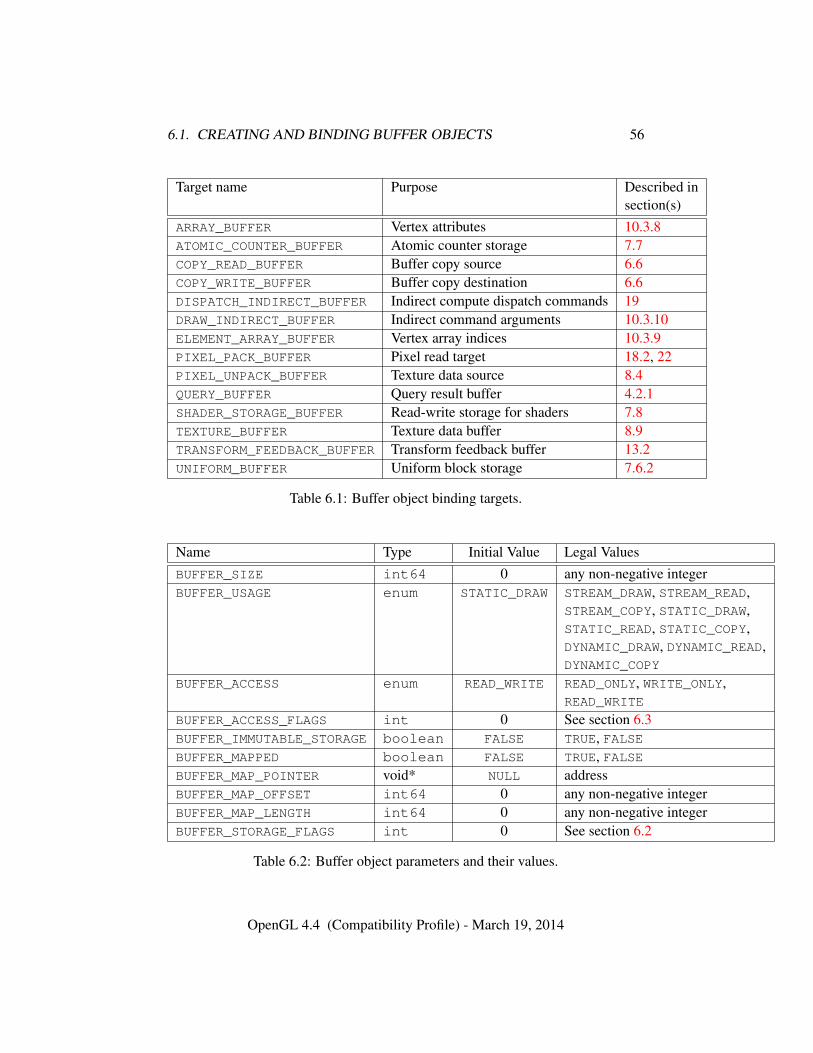
6.1. CREATING AND BINDING BUFFER OBJECTS 56
Target name Purpose Described insection(s)
ARRAY_BUFFER Vertex attributes 10.3.8ATOMIC_COUNTER_BUFFER Atomic counter storage 7.7COPY_READ_BUFFER Buffer copy source 6.6COPY_WRITE_BUFFER Buffer copy destination 6.6DISPATCH_INDIRECT_BUFFER Indirect compute dispatch commands 19DRAW_INDIRECT_BUFFER Indirect command arguments 10.3.10ELEMENT_ARRAY_BUFFER Vertex array indices 10.3.9PIXEL_PACK_BUFFER Pixel read target 18.2, 22PIXEL_UNPACK_BUFFER Texture data source 8.4QUERY_BUFFER Query result buffer 4.2.1SHADER_STORAGE_BUFFER Read-write storage for shaders 7.8TEXTURE_BUFFER Texture data buffer 8.9TRANSFORM_FEEDBACK_BUFFER Transform feedback buffer 13.2UNIFORM_BUFFER Uniform block storage 7.6.2
Table 6.1: Buffer object binding targets.
Name Type Initial Value Legal ValuesBUFFER_SIZE int64 0 any non-negative integerBUFFER_USAGE enum STATIC_DRAW STREAM_DRAW, STREAM_READ,
STREAM_COPY, STATIC_DRAW,STATIC_READ, STATIC_COPY,DYNAMIC_DRAW, DYNAMIC_READ,DYNAMIC_COPY
BUFFER_ACCESS enum READ_WRITE READ_ONLY, WRITE_ONLY,READ_WRITE
BUFFER_ACCESS_FLAGS int 0 See section 6.3BUFFER_IMMUTABLE_STORAGE boolean FALSE TRUE, FALSEBUFFER_MAPPED boolean FALSE TRUE, FALSEBUFFER_MAP_POINTER void* NULL addressBUFFER_MAP_OFFSET int64 0 any non-negative integerBUFFER_MAP_LENGTH int64 0 any non-negative integerBUFFER_STORAGE_FLAGS int 0 See section 6.2
Table 6.2: Buffer object parameters and their values.
OpenGL 4.4 (Compatibility Profile) - March 19, 2014
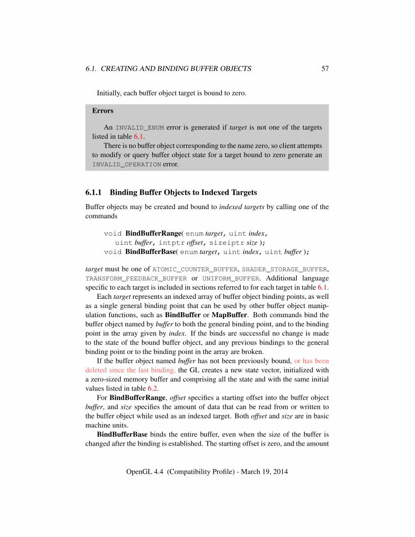
6.1. CREATING AND BINDING BUFFER OBJECTS 57
Initially, each buffer object target is bound to zero.
Errors
An INVALID_ENUM error is generated if target is not one of the targetslisted in table 6.1.
There is no buffer object corresponding to the name zero, so client attemptsto modify or query buffer object state for a target bound to zero generate anINVALID_OPERATION error.
6.1.1 Binding Buffer Objects to Indexed Targets
Buffer objects may be created and bound to indexed targets by calling one of thecommands
void BindBufferRange( enum target, uint index,uint buffer, intptr offset, sizeiptr size );
void BindBufferBase( enum target, uint index, uint buffer );
target must be one of ATOMIC_COUNTER_BUFFER, SHADER_STORAGE_BUFFER,TRANSFORM_FEEDBACK_BUFFER or UNIFORM_BUFFER. Additional languagespecific to each target is included in sections referred to for each target in table 6.1.
Each target represents an indexed array of buffer object binding points, as wellas a single general binding point that can be used by other buffer object manip-ulation functions, such as BindBuffer or MapBuffer. Both commands bind thebuffer object named by buffer to both the general binding point, and to the bindingpoint in the array given by index. If the binds are successful no change is madeto the state of the bound buffer object, and any previous bindings to the generalbinding point or to the binding point in the array are broken.
If the buffer object named buffer has not been previously bound, or has beendeleted since the last binding, the GL creates a new state vector, initialized witha zero-sized memory buffer and comprising all the state and with the same initialvalues listed in table 6.2.
For BindBufferRange, offset specifies a starting offset into the buffer objectbuffer, and size specifies the amount of data that can be read from or written tothe buffer object while used as an indexed target. Both offset and size are in basicmachine units.
BindBufferBase binds the entire buffer, even when the size of the buffer ischanged after the binding is established. The starting offset is zero, and the amount
OpenGL 4.4 (Compatibility Profile) - March 19, 2014
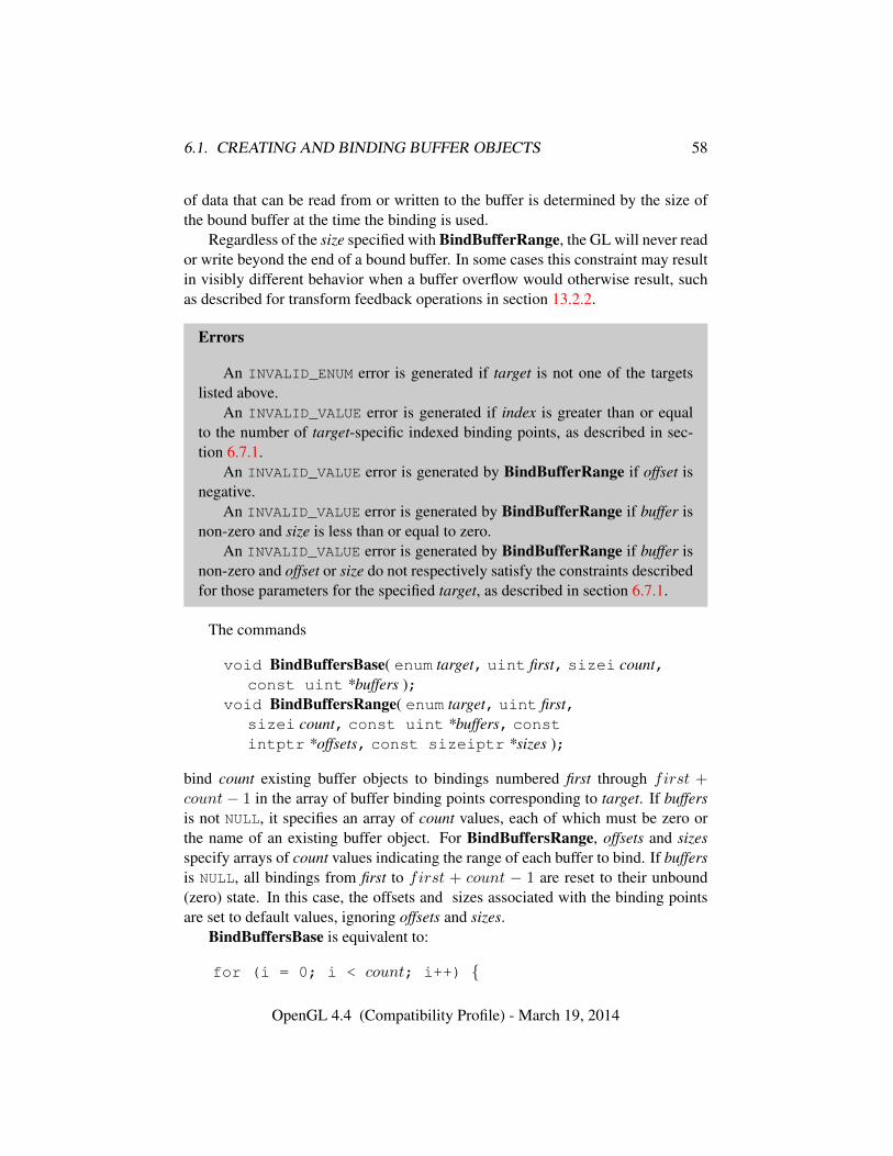
6.1. CREATING AND BINDING BUFFER OBJECTS 58
of data that can be read from or written to the buffer is determined by the size ofthe bound buffer at the time the binding is used.
Regardless of the size specified with BindBufferRange, the GL will never reador write beyond the end of a bound buffer. In some cases this constraint may resultin visibly different behavior when a buffer overflow would otherwise result, suchas described for transform feedback operations in section 13.2.2.
Errors
An INVALID_ENUM error is generated if target is not one of the targetslisted above.
An INVALID_VALUE error is generated if index is greater than or equalto the number of target-specific indexed binding points, as described in sec-tion 6.7.1.
An INVALID_VALUE error is generated by BindBufferRange if offset isnegative.
An INVALID_VALUE error is generated by BindBufferRange if buffer isnon-zero and size is less than or equal to zero.
An INVALID_VALUE error is generated by BindBufferRange if buffer isnon-zero and offset or size do not respectively satisfy the constraints describedfor those parameters for the specified target, as described in section 6.7.1.
The commands
void BindBuffersBase( enum target, uint first, sizei count,const uint *buffers );
void BindBuffersRange( enum target, uint first,sizei count, const uint *buffers, constintptr *offsets, const sizeiptr *sizes );
bind count existing buffer objects to bindings numbered first through first +count − 1 in the array of buffer binding points corresponding to target. If buffersis not NULL, it specifies an array of count values, each of which must be zero orthe name of an existing buffer object. For BindBuffersRange, offsets and sizesspecify arrays of count values indicating the range of each buffer to bind. If buffersis NULL, all bindings from first to first + count − 1 are reset to their unbound(zero) state. In this case, the offsets and sizes associated with the binding pointsare set to default values, ignoring offsets and sizes.
BindBuffersBase is equivalent to:
for (i = 0; i < count; i++) {
OpenGL 4.4 (Compatibility Profile) - March 19, 2014
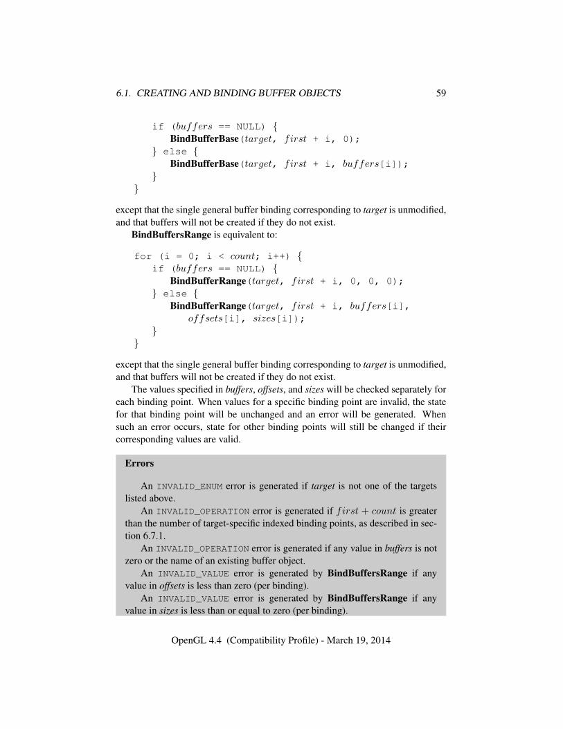
6.1. CREATING AND BINDING BUFFER OBJECTS 59
if (buffers == NULL) {BindBufferBase(target, first + i, 0);
} else {BindBufferBase(target, first + i, buffers[i]);
}}
except that the single general buffer binding corresponding to target is unmodified,and that buffers will not be created if they do not exist.
BindBuffersRange is equivalent to:
for (i = 0; i < count; i++) {if (buffers == NULL) {
BindBufferRange(target, first + i, 0, 0, 0);} else {
BindBufferRange(target, first + i, buffers[i],offsets[i], sizes[i]);
}}
except that the single general buffer binding corresponding to target is unmodified,and that buffers will not be created if they do not exist.
The values specified in buffers, offsets, and sizes will be checked separately foreach binding point. When values for a specific binding point are invalid, the statefor that binding point will be unchanged and an error will be generated. Whensuch an error occurs, state for other binding points will still be changed if theircorresponding values are valid.
Errors
An INVALID_ENUM error is generated if target is not one of the targetslisted above.
An INVALID_OPERATION error is generated if first + count is greaterthan the number of target-specific indexed binding points, as described in sec-tion 6.7.1.
An INVALID_OPERATION error is generated if any value in buffers is notzero or the name of an existing buffer object.
An INVALID_VALUE error is generated by BindBuffersRange if anyvalue in offsets is less than zero (per binding).
An INVALID_VALUE error is generated by BindBuffersRange if anyvalue in sizes is less than or equal to zero (per binding).
OpenGL 4.4 (Compatibility Profile) - March 19, 2014
6.2. CREATING AND MODIFYING BUFFER OBJECT DATA STORES 60
An INVALID_VALUE error is generated by BindBuffersRange if any pairof values in offsets and sizes does not respectively satisfy the constraintsdescribed for those parameters for the specified target, as described in sec-tion 6.7.1 (per binding).
6.2 Creating and Modifying Buffer Object Data Stores
The data store of a buffer object is created by calling
void BufferStorage( enum target, sizeiptr size, constvoid *data, bitfield flags );
with target set to one of the targets listed in table 6.1, size set to the size of thedata store in basic machine units, and flags containing a bitfield describing theintended usage of the data store. The data store of the buffer object bound to targetis allocated as a result of a call to this function and cannot be de-allocated until thebuffer is deleted with a call to DeleteBuffers. Such a store may not be re-allocatedthrough further calls to BufferStorage or BufferData.
data specifies the address in client memory of the data that should be used toinitialize the buffer’s data store. If data is NULL, the data store of the buffer iscreated, but contains undefined data. Otherwise, data should point to an array of atleast size basic machine units.
flags is the bitwise OR of flags describing the intended usage of the bufferobject’s data store by the application. Valid flags and their meanings are as follows:
DYNAMIC_STORAGE_BIT The contents of the data store may be updated after cre-ation through calls to BufferSubData. If this bit is not set, the buffer contentmay not be directly updated by the client. The data argument may be usedto specify the initial content of the buffer’s data store regardless of the pres-ence of the DYNAMIC_STORAGE_BIT. Regardless of the presence of this bit,buffers may always be updated with server-side calls such as CopyBuffer-SubData and ClearBufferSubData.
MAP_READ_BIT The data store may be mapped by the client for read access and apointer in the client’s address space obtained that may be read from.
MAP_WRITE_BIT The data store may be mapped by the client for write access anda pointer in the client’s address space obtained that may be written to.
MAP_PERSISTENT_BIT The client may request that the server read from or writeto the buffer while it is mapped. The client’s pointer to the data store remains
OpenGL 4.4 (Compatibility Profile) - March 19, 2014
6.2. CREATING AND MODIFYING BUFFER OBJECT DATA STORES 61
valid so long as the data store is mapped, even during execution of drawingor dispatch commands.
MAP_COHERENT_BIT Shared access to buffers that are simultaneously mappedfor client access and are used by the server will be coherent, so long as thatmapping is performed using MapBufferRange. That is, data written to thestore by either the client or server will be visible to any subsequently issuedGL commands with no further action taken by the application. In particular,
• If MAP_COHERENT_BIT is not set and the client performs a write fol-lowed by a call to the MemoryBarrier command with the CLIENT_-MAPPED_BUFFER_BARRIER_BIT set, then in subsequent commandsthe server will see the writes.
• If MAP_COHERENT_BIT is set and the client performs a write, then insubsequent commands the server will see the writes.
• If MAP_COHERENT_BIT is not set and the server performs a write, theapplication must call MemoryBarrier with the CLIENT_MAPPED_-
BUFFER_BARRIER_BIT set and then call FenceSync with SYNC_-
GPU_COMMANDS_COMPLETE (or Finish). Then the CPU will see thewrites after the sync is complete.
• If MAP_COHERENT_BIT is set and the server does a write, the app mustcall FenceSync with SYNC_GPU_COMMANDS_COMPLETE (or Finish).Then the CPU will see the writes after the sync is complete.
CLIENT_STORAGE_BIT When all other criteria for the buffer storage allocationare met, this bit may be used by an implementation to determine whether touse storage that is local to the server or to the client to serve as the backingstore for the buffer.
If flags contains MAP_PERSISTENT_BIT, it must also contain at least one ofMAP_READ_BIT or MAP_WRITE_BIT.
It is an error to specify MAP_COHERENT_BIT without also specifying MAP_-
PERSISTENT_BIT.BufferStorage deletes any existing data store, and sets the values of the buffer
object’s state variables as shown in table 6.3.If any portion of the buffer object is mapped in the current context or any
context current to another thread, it is as though UnmapBuffer (see section 6.3.1)is executed in each such context prior to deleting the existing data store.
OpenGL 4.4 (Compatibility Profile) - March 19, 2014
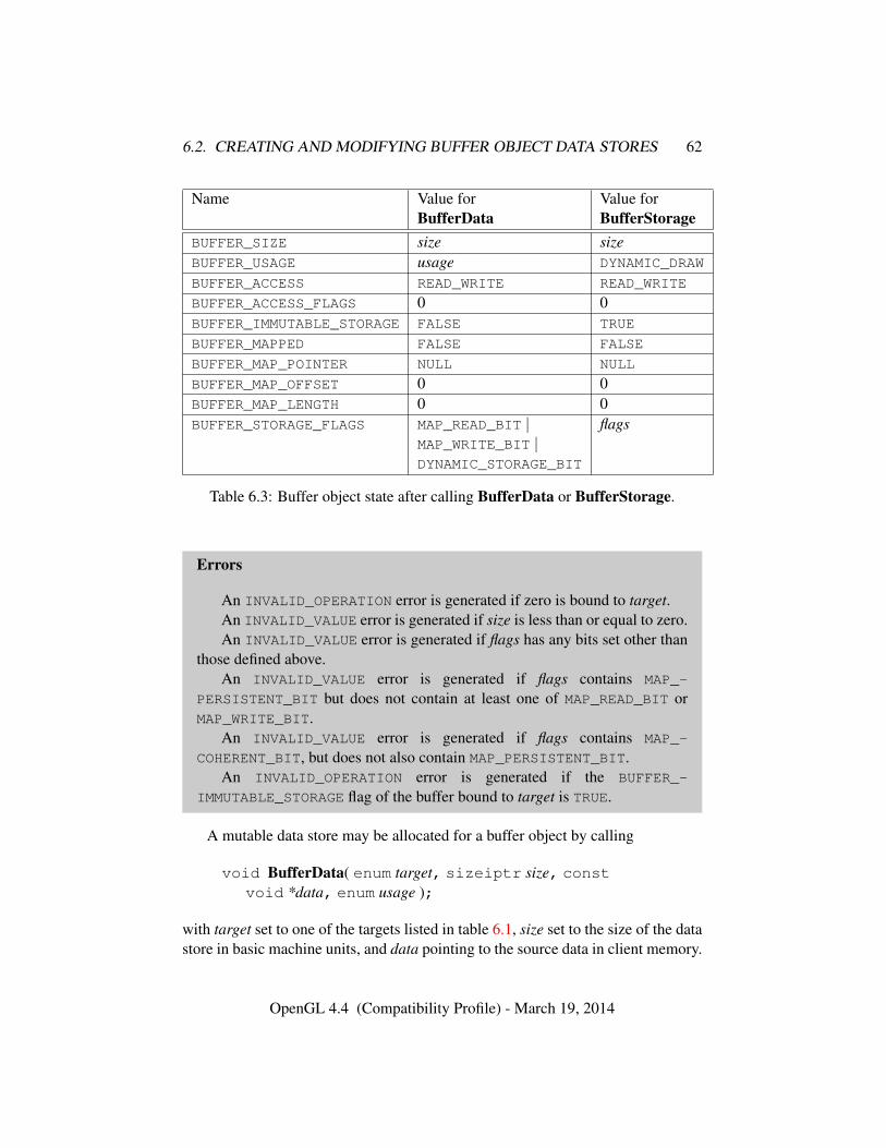
6.2. CREATING AND MODIFYING BUFFER OBJECT DATA STORES 62
Name Value for Value forBufferData BufferStorage
BUFFER_SIZE size sizeBUFFER_USAGE usage DYNAMIC_DRAW
BUFFER_ACCESS READ_WRITE READ_WRITE
BUFFER_ACCESS_FLAGS 0 0BUFFER_IMMUTABLE_STORAGE FALSE TRUE
BUFFER_MAPPED FALSE FALSE
BUFFER_MAP_POINTER NULL NULL
BUFFER_MAP_OFFSET 0 0BUFFER_MAP_LENGTH 0 0BUFFER_STORAGE_FLAGS MAP_READ_BIT | flags
MAP_WRITE_BIT |DYNAMIC_STORAGE_BIT
Table 6.3: Buffer object state after calling BufferData or BufferStorage.
Errors
An INVALID_OPERATION error is generated if zero is bound to target.An INVALID_VALUE error is generated if size is less than or equal to zero.An INVALID_VALUE error is generated if flags has any bits set other than
those defined above.An INVALID_VALUE error is generated if flags contains MAP_-
PERSISTENT_BIT but does not contain at least one of MAP_READ_BIT orMAP_WRITE_BIT.
An INVALID_VALUE error is generated if flags contains MAP_-
COHERENT_BIT, but does not also contain MAP_PERSISTENT_BIT.An INVALID_OPERATION error is generated if the BUFFER_-
IMMUTABLE_STORAGE flag of the buffer bound to target is TRUE.
A mutable data store may be allocated for a buffer object by calling
void BufferData( enum target, sizeiptr size, constvoid *data, enum usage );
with target set to one of the targets listed in table 6.1, size set to the size of the datastore in basic machine units, and data pointing to the source data in client memory.
OpenGL 4.4 (Compatibility Profile) - March 19, 2014
6.2. CREATING AND MODIFYING BUFFER OBJECT DATA STORES 63
If data is non-NULL, then the source data is copied to the buffer object’s data store.If data is NULL, then the contents of the buffer object’s data store are undefined.
usage is specified as one of nine enumerated values, indicating the expectedapplication usage pattern of the data store. In the following descriptions, a buffer’sdata store is sourced when if is read from as a result of GL commands whichspecify images, or invoke shaders accessing buffer data as a result of drawing com-mands or compute shader dispatch.
The values are:
STREAM_DRAW The data store contents will be specified once by the application,and sourced at most a few times.
STREAM_READ The data store contents will be specified once by reading data fromthe GL, and queried at most a few times by the application.
STREAM_COPY The data store contents will be specified once by reading data fromthe GL, and sourced at most a few times
STATIC_DRAW The data store contents will be specified once by the application,and sourced many times.
STATIC_READ The data store contents will be specified once by reading data fromthe GL, and queried many times by the application.
STATIC_COPY The data store contents will be specified once by reading data fromthe GL, and sourced many times.
DYNAMIC_DRAW The data store contents will be respecified repeatedly by the ap-plication, and sourced many times.
DYNAMIC_READ The data store contents will be respecified repeatedly by readingdata from the GL, and queried many times by the application.
DYNAMIC_COPY The data store contents will be respecified repeatedly by readingdata from the GL, and sourced many times.
usage is provided as a performance hint only. The specified usage value doesnot constrain the actual usage pattern of the data store.
BufferData deletes any existing data store, and sets the values of the bufferobject’s state variables as shown in table 6.3.
If any portion of the buffer object is mapped in the current context or anycontext current to another thread, it is as though UnmapBuffer (see section 6.3.1)is executed in each such context prior to deleting the existing data store.
OpenGL 4.4 (Compatibility Profile) - March 19, 2014
6.2. CREATING AND MODIFYING BUFFER OBJECT DATA STORES 64
Clients must align data elements consistent with the requirements of the clientplatform, with an additional base-level requirement that an offset within a buffer toa datum comprising N basic machine units be a multiple of N .
Calling BufferData is equivalent to calling BufferStorage with target, sizeand data as specified, and flags set to the logical OR of DYNAMIC_STORAGE_BIT,MAP_READ_BIT and MAP_WRITE_BIT. The GL will use the value of the usageparameter to BufferData as a hint to further determine the intended use of thebuffer. However, BufferStorage allocates immutable storage whereas BufferDataallocates mutable storage. Thus, when a buffer’s data store is allocated througha call to BufferData, the buffer’s BUFFER_IMMUTABLE_STORAGE flag is set toFALSE.
Errors
An INVALID_OPERATION error is generated if zero is bound to target.An INVALID_VALUE error is generated if size is negative.An INVALID_ENUM error is generated if target is not one of the targets
listed in table 6.1.An INVALID_OPERATION error is generated if the BUFFER_-
IMMUTABLE_STORAGE flag of the buffer bound to target is TRUE.An INVALID_ENUM error is generated if usage is not one of the nine us-
ages described above.
To modify some or all of the data contained in a buffer object’s data store, theclient may use the command
void BufferSubData( enum target, intptr offset,sizeiptr size, const void *data );
with target set to one of the targets listed in table 6.1. offset and size indicate therange of data in the buffer object that is to be replaced, in terms of basic machineunits. data specifies a region of client memory size basic machine units in length,containing the data that replace the specified buffer range.
Errors
An INVALID_OPERATION error is generated if zero is bound to target.An INVALID_ENUM error is generated if target is not one of the targets
listed in table 6.1.An INVALID_VALUE error is generated if offset or size is negative, or if
offset + size is greater than the value of BUFFER_SIZE for the buffer bound
OpenGL 4.4 (Compatibility Profile) - March 19, 2014
6.2. CREATING AND MODIFYING BUFFER OBJECT DATA STORES 65
to target.An INVALID_OPERATION error is generated if any part of the speci-
fied buffer range is mapped with MapBufferRange or MapBuffer (see sec-tion 6.3), unless it was mapped with MAP_PERSISTENT_BIT set in the Map-BufferRange access flags.
An INVALID_OPERATION error is generated if the BUFFER_-
IMMUTABLE_STORAGE flag of the buffer bound to target is TRUE and the valueof BUFFER_STORAGE_FLAGS for the buffer does not have the DYNAMIC_-
STORAGE_BIT set.
6.2.1 Clearing Buffer Object Data Stores
To fill all or part of an existing buffer object’s data store with constant values, call
void ClearBufferSubData( enum target, enum internalformat,intptr offset, sizeiptr size, enum format, enum type,const void *data );
with target set to the target to which the destination buffer is bound. target mustbe one of the targets listed in table 6.1. internalformat must be set to one of theformat tokens listed in table 8.23. format and type specify the format and type ofthe source data and are interpreted as described in section 8.4.4.
offset is the offset, measured in basic machine units, into the buffer object’sdata store from which to begin filling, and size is the size, also in basic machineunits, of the range to fill.
data is a pointer to an array of between one and four components containingthe data to be used as the source of the constant fill value. The elements of dataare converted by the GL into the format specified by internalformat in the mannerdescribed in section 2.2.1, and then used to fill the specified range of the destinationbuffer. If data is NULL, then the pointer is ignored and the sub-range of the bufferis filled with zeros.
Errors
An INVALID_ENUM error is generated if target is not one of the targetslisted in table 6.1.
An INVALID_VALUE error is generated if zero is bound to target.An INVALID_ENUM error is generated if internalformat is not one of the
format tokens listed in table 8.23.An INVALID_VALUE error is generated if offset or size are not multiples
of the number of basic machine units for the internal format specified by inter-
OpenGL 4.4 (Compatibility Profile) - March 19, 2014
6.3. MAPPING AND UNMAPPING BUFFER DATA 66
nalformat. This value may be computed by multiplying the number of compo-nents for internalformat from table 8.23 by the size if the base type from thattable.
An INVALID_VALUE error is generated if offset or size is negative, or ifoffset + size is greater than the value of BUFFER_SIZE for the buffer boundto target.
An INVALID_OPERATION error is generated if any part of the speci-fied buffer range is mapped with MapBufferRange or MapBuffer (see sec-tion 6.3), unless it was mapped with MAP_PERSISTENT_BIT set in the Map-BufferRange access flags.
An INVALID_VALUE error is generated if type is not one of the types intable 8.7.
An INVALID_VALUE error is generated if format is not one of the formatsin table 8.8.
The command
void ClearBufferData( enum target, enum internalformat,enum format, enum type, const void *data );
is equivalent to calling ClearBufferSubData with target, internalformat and dataas specified, offset zero, and size set to the value of BUFFER_SIZE for the bufferbound to target.
6.3 Mapping and Unmapping Buffer Data
All or part of the data store of a buffer object may be mapped into the client’saddress space by calling
void *MapBufferRange( enum target, intptr offset,sizeiptr length, bitfield access );
with target set to one of the targets listed in table 6.1. offset and length indicate therange of data in the buffer object that is to be mapped, in terms of basic machineunits. access is a bitfield containing flags which describe the requested mapping.These flags are described below.
If no error occurs, a pointer to the beginning of the mapped range is returnedonce all pending operations on that buffer have completed, and may be used tomodify and/or query the corresponding range of the buffer, according to the fol-lowing flag bits set in access:
OpenGL 4.4 (Compatibility Profile) - March 19, 2014
6.3. MAPPING AND UNMAPPING BUFFER DATA 67
• MAP_READ_BIT indicates that the returned pointer may be used to readbuffer object data. No GL error is generated if the pointer is used to querya mapping which excludes this flag, but the result is undefined and systemerrors (possibly including program termination) may occur.
• MAP_WRITE_BIT indicates that the returned pointer may be used to modifybuffer object data. No GL error is generated if the pointer is used to modifya mapping which excludes this flag, but the result is undefined and systemerrors (possibly including program termination) may occur.
• MAP_PERSISTENT_BIT indicates that it is not an error for the GL to readdata from or write data to the buffer while it is mapped (see section 6.3.2).If this bit is set, the value of BUFFER_STORAGE_FLAGS for the buffer beingmapped must include MAP_PERSISTENT_BIT.
• MAP_COHERENT_BIT indicates that the mapping should be performed co-herently. That is, such a mapping follows the rules set forth in section 6.2.If this bit is set, the value of BUFFER_STORAGE_FLAGS for the buffer beingmapped must include MAP_COHERENT_BIT.
If no error occurs, the pointer value returned by MapBufferRange must re-flect an allocation aligned to the value of MIN_MAP_BUFFER_ALIGNMENT basicmachine units. Subtracting offset basic machine units from the returned pointerwill always produce a multiple of the value of MIN_MAP_BUFFER_ALIGNMENT.
Pointer values returned by MapBufferRange may not be passed as parametervalues to GL commands. For example, they may not be used to specify arraypointers, or to specify or query pixel or texture image data; such actions produceundefined results, although implementations may not check for such behavior forperformance reasons.
Mappings to the data stores of buffer objects may have nonstandard perfor-mance characteristics. For example, such mappings may be marked as uncacheableregions of memory, and in such cases reading from them may be very slow. To en-sure optimal performance, the client should use the mapping in a fashion consistentwith the values of BUFFER_USAGE and access. Using a mapping in a fashion in-consistent with these values is liable to be multiple orders of magnitude slowerthan using normal memory.
The following optional flag bits in access may be used to modify the mapping:
• MAP_INVALIDATE_RANGE_BIT indicates that the previous contents of thespecified range may be discarded. Data within this range are undefined withthe exception of subsequently written data. No GL error is generated if sub-sequent GL operations access unwritten data, but the result is undefined and
OpenGL 4.4 (Compatibility Profile) - March 19, 2014
6.3. MAPPING AND UNMAPPING BUFFER DATA 68
system errors (possibly including program termination) may occur. This flagmay not be used in combination with MAP_READ_BIT.
• MAP_INVALIDATE_BUFFER_BIT indicates that the previous contents of theentire buffer may be discarded. Data within the entire buffer are undefinedwith the exception of subsequently written data. No GL error is generated ifsubsequent GL operations access unwritten data, but the result is undefinedand system errors (possibly including program termination) may occur. Thisflag may not be used in combination with MAP_READ_BIT.
• MAP_FLUSH_EXPLICIT_BIT indicates that one or more discrete subrangesof the mapping may be modified. When this flag is set, modifications toeach subrange must be explicitly flushed by calling FlushMappedBuffer-Range. No GL error is set if a subrange of the mapping is modified andnot flushed, but data within the corresponding subrange of the buffer are un-defined. This flag may only be used in conjunction with MAP_WRITE_BIT.When this option is selected, flushing is strictly limited to regions that areexplicitly indicated with calls to FlushMappedBufferRange prior to un-map; if this option is not selected UnmapBuffer will automatically flush theentire mapped range when called.
• MAP_UNSYNCHRONIZED_BIT indicates that the GL should not attempt tosynchronize pending operations on the buffer prior to returning from Map-BufferRange. No GL error is generated if pending operations which sourceor modify the buffer overlap the mapped region, but the result of such previ-ous and any subsequent operations is undefined.
A successful MapBufferRange sets buffer object state values as shown in ta-ble 6.4.
Errors
If an error occurs, MapBufferRange returns a NULL pointer.An INVALID_VALUE error is generated if offset or length is negative, if
offset + length is greater than the value of BUFFER_SIZE, or if access hasany bits set other than those defined above.
An INVALID_OPERATION error is generated for any of the following con-ditions:• length is zero.
• Zero is bound to target.
OpenGL 4.4 (Compatibility Profile) - March 19, 2014
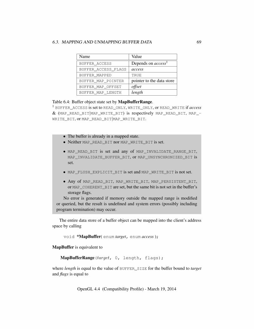
6.3. MAPPING AND UNMAPPING BUFFER DATA 69
Name ValueBUFFER_ACCESS Depends on access1
BUFFER_ACCESS_FLAGS accessBUFFER_MAPPED TRUE
BUFFER_MAP_POINTER pointer to the data storeBUFFER_MAP_OFFSET offsetBUFFER_MAP_LENGTH length
Table 6.4: Buffer object state set by MapBufferRange.1 BUFFER_ACCESS is set to READ_ONLY, WRITE_ONLY, or READ_WRITE if access& (MAP_READ_BIT|MAP_WRITE_BIT) is respectively MAP_READ_BIT, MAP_-WRITE_BIT, or MAP_READ_BIT|MAP_WRITE_BIT.
• The buffer is already in a mapped state.• Neither MAP_READ_BIT nor MAP_WRITE_BIT is set.
• MAP_READ_BIT is set and any of MAP_INVALIDATE_RANGE_BIT,MAP_INVALIDATE_BUFFER_BIT, or MAP_UNSYNCHRONIZED_BIT isset.
• MAP_FLUSH_EXPLICIT_BIT is set and MAP_WRITE_BIT is not set.
• Any of MAP_READ_BIT, MAP_WRITE_BIT, MAP_PERSISTENT_BIT,or MAP_COHERENT_BIT are set, but the same bit is not set in the buffer’sstorage flags.
No error is generated if memory outside the mapped range is modifiedor queried, but the result is undefined and system errors (possibly includingprogram termination) may occur.
The entire data store of a buffer object can be mapped into the client’s addressspace by calling
void *MapBuffer( enum target, enum access );
MapBuffer is equivalent to
MapBufferRange(target, 0, length, flags);
where length is equal to the value of BUFFER_SIZE for the buffer bound to targetand flags is equal to
OpenGL 4.4 (Compatibility Profile) - March 19, 2014
6.3. MAPPING AND UNMAPPING BUFFER DATA 70
• MAP_READ_BIT, if access is READ_ONLY
• MAP_WRITE_BIT, if access is WRITE_ONLY
• MAP_READ_BIT | MAP_WRITE_BIT, if access is READ_WRITE.
The pointer value returned by MapBuffer must be aligned to the value ofMIN_MAP_BUFFER_ALIGNMENT basic machine units.
Errors
An INVALID_ENUM error is generated if access is not READ_ONLY,WRITE_ONLY, or READ_WRITE.
Other errors are generated as described above for MapBufferRange.
If a buffer is mapped with the MAP_FLUSH_EXPLICIT_BIT flag, modificationsto the mapped range may be indicated by calling
void FlushMappedBufferRange( enum target, intptr offset,sizeiptr length );
with target set to one of the targets listed in table 6.1. offset and length indi-cate a modified subrange of the mapping, in basic machine units. The specifiedsubrange to flush is relative to the start of the currently mapped range of buffer.FlushMappedBufferRange may be called multiple times to indicate distinct sub-ranges of the mapping which require flushing.
If a buffer range is mapped with both MAP_PERSISTENT_BIT and MAP_-
FLUSH_EXPLICIT_BIT set, then FlushMappedBufferRange may be called toensure that data written by the client into the flushed region becomes visible to theserver. Data written to a coherent store will always become visible to the serverafter an unspecified period of time.
Errors
An INVALID_ENUM error is generated if target is not one of the targetslisted in table 6.1.
An INVALID_OPERATION error is generated if zero is bound to target.An INVALID_OPERATION error is generated if the buffer bound to target
is not mapped, or is mapped without the MAP_FLUSH_EXPLICIT_BIT flag.An INVALID_VALUE error is generated if offset or length is negative, or if
offset + length exceeds the size of the mapping.
OpenGL 4.4 (Compatibility Profile) - March 19, 2014
6.3. MAPPING AND UNMAPPING BUFFER DATA 71
6.3.1 Unmapping Buffers
After the client has specified the contents of a mapped buffer range, and before thedata in that range are dereferenced by any GL commands, the mapping must berelinquished by calling
boolean UnmapBuffer( enum target );
with target set to one of the targets listed in table 6.1. Unmapping a mapped bufferobject invalidates the pointer to its data store and sets the object’s BUFFER_-
MAPPED, BUFFER_MAP_POINTER, BUFFER_ACCESS_FLAGS, BUFFER_MAP_-
OFFSET, and BUFFER_MAP_LENGTH state variables to the initial values shown intable 6.3.
UnmapBuffer returns TRUE unless data values in the buffer’s data store havebecome corrupted during the period that the buffer was mapped. Such corruptioncan be the result of a screen resolution change or other window system-dependentevent that causes system heaps such as those for high-performance graphics mem-ory to be discarded. GL implementations must guarantee that such corruption canoccur only during the periods that a buffer’s data store is mapped. If such corrup-tion has occurred, UnmapBuffer returns FALSE, and the contents of the buffer’sdata store become undefined.
Unmapping that occurs as a side effect of buffer deletion (see section 5.1.2) orreinitialization by BufferData is not an error.
Buffer mappings are buffer object state, and are not affected by whether or nota context owing a buffer object is current.
Errors
An INVALID_OPERATION error is generated if the buffer data store isalready in the unmapped state, and FALSE is returned.
6.3.2 Effects of Mapping Buffers on Other GL Commands
Any GL command which attempts to read from, write to, or change the state ofa buffer object may generate an INVALID_OPERATION error if all or part of thebuffer object is mapped, unless it was allocated by a call to BufferStorage withthe MAP_PERSISTENT_BIT included in flags. However, only commands whichexplicitly describe this error are required to do so. If an error is not generated,using such commands to perform invalid reads, writes, or state changes will haveundefined results and may result in GL interruption or termination.
OpenGL 4.4 (Compatibility Profile) - March 19, 2014
6.4. EFFECTS OF ACCESSING OUTSIDE BUFFER BOUNDS 72
6.4 Effects of Accessing Outside Buffer Bounds
Most, but not all GL commands operating on buffer objects will detect attempts toread from or write to a location in a bound buffer object at an offset less than zero,or greater than or equal to the buffer’s size. When such an attempt is detected, aGL error is generated. Any command which does not detect these attempts, andperforms such an invalid read or write, has undefined results, and may result in GLinterruption or termination.
Robust buffer access can be enabled by creating a context with robust accessenabled through the window system binding APIs. When enabled, any commandunable to generate a GL error as described above, such as buffer object accessesfrom the active program, will not read or modify memory outside of the data storeof the buffer object and will not result in GL interruption or termination. Out-of-bounds reads may return values from within the buffer object or zero values.Out-of-bounds writes may modify values within the buffer object or be discarded.Accesses made through resources attached to binding points are only protectedwithin the buffer object from which the binding point is declared. For example,for an out-of-bounds access to a member variable of a uniform block, the accessprotection is provided within the uniform buffer object, and not for the bound bufferrange for this uniform block.
6.5 Invalidating Buffer Data
All or part of the data store of a buffer object may be invalidated by calling
void InvalidateBufferSubData( uint buffer, intptr offset,sizeiptr length );
with buffer set to the name of the buffer whose data store is being invalidated. offsetand length specify the range of the data in the buffer object that is to be invalidated.Data in the specified range have undefined values after calling InvalidateBuffer-SubData.
Errors
An INVALID_VALUE error is generated if buffer is zero or is not the nameof an existing buffer object.
An INVALID_VALUE error is generated if offset or length is negative, or ifoffset + length is greater than the value of BUFFER_SIZE for buffer.
An INVALID_OPERATION error is generated if buffer is currently mapped
OpenGL 4.4 (Compatibility Profile) - March 19, 2014
6.6. COPYING BETWEEN BUFFERS 73
by MapBuffer or if the invalidate range intersects the range currently mappedby MapBufferRange, unless it was mapped with MAP_PERSISTENT_BIT setin the MapBufferRange access flags.
The command
void InvalidateBufferData( uint buffer );
is equivalent to calling InvalidateBufferSubData with offset equal to zero andlength equal to the value of BUFFER_SIZE for buffer.
6.6 Copying Between Buffers
All or part of the data store of a buffer object may be copied to the data store ofanother buffer object by calling
void CopyBufferSubData( enum readtarget, enum writetarget,intptr readoffset, intptr writeoffset, sizeiptr size );
with readtarget and writetarget each set to one of the targets listed in table 6.1.While any of these targets may be used, the COPY_READ_BUFFER and COPY_-
WRITE_BUFFER targets are provided specifically for copies, so that they can bedone without affecting other buffer binding targets that may be in use.
writeoffset and size specify the range of data in the buffer object bound to write-target that is to be replaced, in terms of basic machine units. readoffset and sizespecify the range of data in the buffer object bound to readtarget that is to be copiedto the corresponding region of writetarget.
Errors
An INVALID_VALUE error is generated if any of readoffset, writeoffset,or size are negative, if readoffset + size exceeds the size of the buffer objectbound to readtarget, or if writeoffset + size exceeds the size of the bufferobject bound to writetarget.
An INVALID_VALUE error is generated if the same buffer object is boundto both readtarget and writetarget, and the ranges [readoffset , readoffset +size) and [writeoffset ,writeoffset + size) overlap.
An INVALID_OPERATION error is generated if zero is bound to readtargetor writetarget.
An INVALID_OPERATION error is generated if the buffer objects boundto either readtarget or writetarget are mapped, unless they were mapped with
OpenGL 4.4 (Compatibility Profile) - March 19, 2014
6.7. BUFFER OBJECT QUERIES 74
MAP_PERSISTENT_BIT set in the MapBufferRange access flags.
6.7 Buffer Object Queries
The commands
void GetBufferParameteriv( enum target, enum pname,int *data );
void GetBufferParameteri64v( enum target, enum pname,int64 *data );
return information about a bound buffer object. target must be one of the targetslisted in table 6.1, and pname must be one of the buffer object parameters in ta-ble 6.2, other than BUFFER_MAP_POINTER. The value of the specified parameterof the buffer object bound to target is returned in data.
Errors
An INVALID_ENUM error is generated if target is not one of the targetslisted in table 6.1.
An INVALID_OPERATION error is generated if zero is bound to target.An INVALID_ENUM error is generated if pname is not one of the buffer
object parameters other than BUFFER_MAP_POINTER.
The command
void GetBufferSubData( enum target, intptr offset,sizeiptr size, void *data );
queries the data contents of a buffer object. target must be one of the targets listedin table 6.1. offset and size indicate the range of data in the buffer object that isto be queried, in terms of basic machine units. data specifies a region of clientmemory, size basic machine units in length, into which the data is to be retrieved.
Errors
An INVALID_ENUM error is generated if target is not one of the targetslisted in table 6.1.
An INVALID_OPERATION error is generated if zero is bound to target.An INVALID_VALUE error is generated if offset or size is negative, or if
offset + size is greater than the value of BUFFER_SIZE for the buffer boundto target.
OpenGL 4.4 (Compatibility Profile) - March 19, 2014
6.7. BUFFER OBJECT QUERIES 75
An INVALID_OPERATION error is generated if the buffer object bound totarget is currently mapped, unless it was mapped with MAP_PERSISTENT_-
BIT set in the MapBufferRange access flags.
While part or all of the data store of a buffer object is mapped, the pointer tothe mapped range of the data store can be queried by calling
void GetBufferPointerv( enum target, enum pname, constvoid **params );
with target set to one of the targets listed in table 6.1 and pname set to BUFFER_-
MAP_POINTER. The single buffer map pointer is returned in params. GetBuffer-Pointerv returns the NULL pointer value if the buffer’s data store is not currentlymapped, or if the requesting context did not map the buffer object’s data store, andthe implementation is unable to support mappings on multiple clients.
Errors
An INVALID_ENUM error is generated if target is not one of the targetslisted in table 6.1.
An INVALID_ENUM error is generated if pname is not BUFFER_MAP_-POINTER.
An INVALID_OPERATION error is generated if zero is bound to target.
6.7.1 Indexed Buffer Object Limits and Binding Queries
Several types of buffer bindings support an indexed array of binding points forspecific use by the GL, in addition to a single generic binding point for generalmanagement of buffers of that type. Each type of binding is described in table 6.5together with the token names used to refer to each buffer in the array of bindingpoints, the starting offset of the binding for each buffer in the array, any constraintson the corresponding offset value passed to BindBufferRange (see section 6.1.1),the size of the binding for each buffer in the array, any constraints on the corre-sponding size value passed to BindBufferRange, and the size of the array (thenumber of bind points supported).
To query which buffer objects are bound to an indexed array, call GetIntegeri -v with target set to the name of the array binding points. index must be in the rangezero to the number of bind points supported minus one. The name of the bufferobject bound to index is returned in values. If no buffer object is bound for index,zero is returned in values.
OpenGL 4.4 (Compatibility Profile) - March 19, 2014
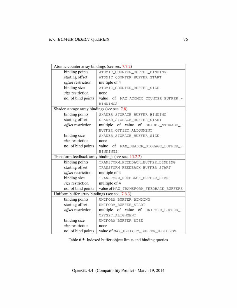
6.7. BUFFER OBJECT QUERIES 76
Atomic counter array bindings (see sec. 7.7.2)binding points ATOMIC_COUNTER_BUFFER_BINDING
starting offset ATOMIC_COUNTER_BUFFER_START
offset restriction multiple of 4binding size ATOMIC_COUNTER_BUFFER_SIZE
size restriction noneno. of bind points value of MAX_ATOMIC_COUNTER_BUFFER_-
BINDINGS
Shader storage array bindings (see sec. 7.8)binding points SHADER_STORAGE_BUFFER_BINDING
starting offset SHADER_STORAGE_BUFFER_START
offset restriction multiple of value of SHADER_STORAGE_-
BUFFER_OFFSET_ALIGNMENT
binding size SHADER_STORAGE_BUFFER_SIZE
size restriction noneno. of bind points value of MAX_SHADER_STORAGE_BUFFER_-
BINDINGS
Transform feedback array bindings (see sec. 13.2.2)binding points TRANSFORM_FEEDBACK_BUFFER_BINDING
starting offset TRANSFORM_FEEDBACK_BUFFER_START
offset restriction multiple of 4binding size TRANSFORM_FEEDBACK_BUFFER_SIZE
size restriction multiple of 4no. of bind points value of MAX_TRANSFORM_FEEDBACK_BUFFERS
Uniform buffer array bindings (see sec. 7.6.3)binding points UNIFORM_BUFFER_BINDING
starting offset UNIFORM_BUFFER_START
offset restriction multiple of value of UNIFORM_BUFFER_-
OFFSET_ALIGNMENT
binding size UNIFORM_BUFFER_SIZE
size restriction noneno. of bind points value of MAX_UNIFORM_BUFFER_BINDINGS
Table 6.5: Indexed buffer object limits and binding queries
OpenGL 4.4 (Compatibility Profile) - March 19, 2014
6.8. BUFFER OBJECT STATE 77
To query the starting offset or size of the range of a buffer object binding inan indexed array, call GetInteger64i v with target set to respectively the startingoffset or binding size name from table 6.5 for that array. index must be in the rangezero to the number of bind points supported minus one. If the starting offset orsize was not specified when the buffer object was bound (e.g. if it was bound withBindBufferBase), or if no buffer object is bound to the target array at index, zerois returned1.
Errors
An INVALID_VALUE error is generated by GetIntegeri v and GetInte-ger64i v if target is one of the array binding point names, starting offsetnames, or binding size names from table 6.5 and index is greater than or equalto the number of binding points for target as described in the same table.
6.8 Buffer Object State
The state required to support buffer objects consists of binding names for each ofthe buffer targets in table 6.1, and for each of the indexed buffer targets in sec-tion 6.1.1. The state required for index buffer targets for atomic counters, shaderstorage, transform feedback, and uniform buffer array bindings is summarized intables 23.57, 23.58, 23.59, and 23.60 respectively.
Additionally, each vertex array has an associated binding so there is a bufferobject binding for each of the vertex array, normal array, color array, index array,multiple texture coordinate arrays, edge flag array, secondary color array, fog co-ordinate array, and vertex attribute arrays. The initial values for all buffer objectbindings is zero.
The state of each buffer object consists of a buffer size in basic machine units, ausage parameter, an access parameter, an boolean indicating whether or not bufferstorage is immutable, an unsigned integer storing the flags with which it was allo-cated, a mapped boolean, two integers for the offset and size of the mapped region,a pointer to the mapped buffer (NULL if unmapped), and the sized array of basicmachine units for the buffer data.
1A zero size is a sentinel value indicating that the actual binding range size is determined by thesize of the bound buffer at the time the binding is used.
OpenGL 4.4 (Compatibility Profile) - March 19, 2014
Chapter 7
Programs and Shaders
This chapter specifies commands to create, manage, and destroy program andshader objects. Commands and functionality applicable only to specific shaderstages (for example, vertex attributes used as inputs by vertex shaders) are de-scribed together with those stages in chapters 10 and 15.
A shader specifies operations that are meant to occur on data as it movesthrough different programmable stages of the OpenGL processing pipeline, start-ing with vertices specified by the application and ending with fragments prior tobeing written to the framebuffer. The programming language used for shaders isdescribed in the OpenGL Shading Language Specification.
To use a shader, shader source code is first loaded into a shader object and thencompiled. A shader object corresponds to a stage in the rendering pipeline referredto as its shader stage or shader type.
Alternatively, pre-compiled shader binary code may be directly loaded into ashader object. An implementation must support shader compilation (the booleanvalue SHADER_COMPILER must be TRUE). If the integer value of NUM_SHADER_-BINARY_FORMATS is greater than zero, then shader binary loading is supported.
One or more shader objects are attached to a program object. The programobject is then linked, which generates executable code from all the compiled shaderobjects attached to the program. Alternatively, pre-compiled program binary codemay be directly loaded into a program object (see section 7.5).
When program objects are bound to a shader stage, they become the currentprogram object for that stage. When the current program object for a shader stageincludes a shader of that type, it is considered the active program object for thatstage.
The current program object for all stages may be set at once using a singleunified program object, or the current program object may be set for each stage
78
7.1. SHADER OBJECTS 79
individually using a separable program object where different separable programobjects may be current for other stages. The set of separable program objectscurrent for all stages are collected in a program pipeline object that must be boundfor use. When a linked program object is made active for one of the stages, thecorresponding executable code is used to perform processing for that stage.
Shader stages including vertex shaders, tessellation control shaders, tessella-tion evaluation shaders, geometry shaders, fragment shaders, and compute shaderscan be created, compiled, and linked into program objects.
Vertex shaders describe the operations that occur on vertex attributes. Tessel-lation control and evaluation shaders are used to control the operation of the tes-sellator, and are described in section 11.2. Geometry shaders affect the processingof primitives assembled from vertices (see section 11.3). Fragment shaders affectthe processing of fragments during rasterization (see section 15). A single programobject can contain all of these shaders, or any subset thereof.
Compute shaders perform general-purpose computation for dispatched arraysof shader invocations (see section 19), but do not operate on primitives processedby the other shader types.
Shaders can reference several types of variables as they execute. Uniformsare per-program variables that are constant during program execution (see sec-tion 7.6). Buffer variables (see section 7.8) are similar to uniforms, but are storedin buffer object memory which may be written to, and is persistent across multipleshader invocations. Subroutine uniform variables (see section 7.9) are similar touniforms but are context state, rather than program object state. Samplers (see sec-tion 7.10) are a special form of uniform used for texturing (see chapter 8). Images(see section 7.11) are a special form of uniform identifying a level of a texture tobe accessed using built-in shader functions as described in section 8.26. Outputvariables hold the results of shader execution that are used later in the pipeline.Each of these variable types is described in more detail below.
7.1 Shader Objects
The name space for shader objects is the unsigned integers, with zero reserved forthe GL. This name space is shared with program objects. The following sectionsdefine commands that operate on shader and program objects.
To create a shader object, use the command
uint CreateShader( enum type );
The shader object is empty when it is created. The type argument specifies the typeof shader object to be created and must be one of the values in table 7.1 indicating
OpenGL 4.4 (Compatibility Profile) - March 19, 2014
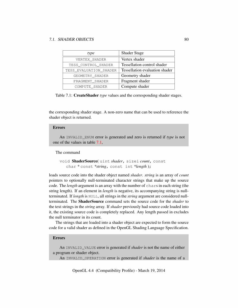
7.1. SHADER OBJECTS 80
type Shader StageVERTEX_SHADER Vertex shader
TESS_CONTROL_SHADER Tessellation control shaderTESS_EVALUATION_SHADER Tessellation evaluation shader
GEOMETRY_SHADER Geometry shaderFRAGMENT_SHADER Fragment shaderCOMPUTE_SHADER Compute shader
Table 7.1: CreateShader type values and the corresponding shader stages.
the corresponding shader stage. A non-zero name that can be used to reference theshader object is returned.
Errors
An INVALID_ENUM error is generated and zero is returned if type is notone of the values in table 7.1,
The command
void ShaderSource( uint shader, sizei count, constchar * const *string, const int *length );
loads source code into the shader object named shader. string is an array of countpointers to optionally null-terminated character strings that make up the sourcecode. The length argument is an array with the number of chars in each string (thestring length). If an element in length is negative, its accompanying string is null-terminated. If length is NULL, all strings in the string argument are considered null-terminated. The ShaderSource command sets the source code for the shader tothe text strings in the string array. If shader previously had source code loaded intoit, the existing source code is completely replaced. Any length passed in excludesthe null terminator in its count.
The strings that are loaded into a shader object are expected to form the sourcecode for a valid shader as defined in the OpenGL Shading Language Specification.
Errors
An INVALID_VALUE error is generated if shader is not the name of eithera program or shader object.
An INVALID_OPERATION error is generated if shader is the name of a
OpenGL 4.4 (Compatibility Profile) - March 19, 2014
7.1. SHADER OBJECTS 81
program object.An INVALID_VALUE error is generated if count is negative.
Once the source code for a shader has been loaded, a shader object can becompiled with the command
void CompileShader( uint shader );
Each shader object has a boolean status, COMPILE_STATUS, that is modified asa result of compilation. This status can be queried with GetShaderiv (see sec-tion 7.13). This status will be set to TRUE if shader was compiled without errorsand is ready for use, and FALSE otherwise. Compilation can fail for a variety ofreasons as listed in the OpenGL Shading Language Specification. If Compile-Shader failed, any information about a previous compile is lost. Thus a failedcompile does not restore the old state of shader.
Changing the source code of a shader object with ShaderSource does notchange its compile status or the compiled shader code.
Each shader object has an information log, which is a text string that is over-written as a result of compilation. This information log can be queried with Get-ShaderInfoLog to obtain more information about the compilation attempt (seesection 7.13).
Errors
An INVALID_VALUE error is generated if shader is not the name of eithera program or shader object.
An INVALID_OPERATION error is generated if shader is the name of aprogram object.
Resources allocated by the shader compiler may be released with the command
void ReleaseShaderCompiler( void );
This is a hint from the application, and does not prevent later use of the shadercompiler. If shader source is loaded and compiled after ReleaseShaderCompilerhas been called, CompileShader must succeed provided there are no errors in theshader source.
The range and precision for different numeric formats supported by the shadercompiler may be determined with the command GetShaderPrecisionFormat (seesection 7.13).
Shader objects can be deleted with the command
OpenGL 4.4 (Compatibility Profile) - March 19, 2014
7.2. SHADER BINARIES 82
void DeleteShader( uint shader );
If shader is not attached to any program object, it is deleted immediately. Oth-erwise, shader is flagged for deletion and will be deleted when it is no longerattached to any program object. If an object is flagged for deletion, its booleanstatus bit DELETE_STATUS is set to true. The value of DELETE_STATUS can bequeried with GetShaderiv (see section 7.13). DeleteShader will silently ignorethe value zero.
Errors
An INVALID_VALUE error is generated if shader is neither zero nor thename of either a program or shader object.
An INVALID_OPERATION error is generated if shader is not zero and isthe name of a program object.
The command
boolean IsShader( uint shader );
returns TRUE if shader is the name of a shader object. If shader is zero, or a non-zero value that is not the name of a shader object, IsShader returns FALSE. Noerror is generated if shader is not a valid shader object name.
7.2 Shader Binaries
Precompiled shader binaries may be loaded with the command
void ShaderBinary( sizei count, const uint *shaders,enum binaryformat, const void *binary, sizei length );
shaders contains a list of count shader object handles. Each handle refers to aunique shader type, and may correspond to any of the shader stages in table 7.1.binary points to length bytes of pre-compiled binary shader code in client memory,and binaryformat denotes the format of the pre-compiled code.
The binary image will be decoded according to the extension specificationdefining the specified binaryformat. OpenGL defines no specific binary formats,but does provide a mechanism to obtain token values for such formats providedby extensions. The number of shader binary formats supported can be obtained byquerying the value of NUM_SHADER_BINARY_FORMATS. The list of specific binary
OpenGL 4.4 (Compatibility Profile) - March 19, 2014
7.3. PROGRAM OBJECTS 83
formats supported can be obtained by querying the value of SHADER_BINARY_-FORMATS.
Depending on the types of the shader objects in shaders, ShaderBinary willindividually load binary shaders, or load an executable binary that contains an op-timized set of shaders stored in the same binary.
Errors
An INVALID_VALUE error is generated if count or length is negative.An INVALID_ENUM error is generated if binaryformat is not a supported
format returned in SHADER_BINARY_FORMATS.An INVALID_VALUE error is generated if the data pointed to by binary
does not match the specified binaryformat.An INVALID_VALUE error is generated if any of the handles in shaders is
not the name of either a program or shader object.An INVALID_OPERATION error is generated if any of the handles in
shader is the name of a program object.An INVALID_OPERATION error is generated if more than one of the han-
dles in shaders refers to the same type of shader object.Additional errors corresponding to specific binary formats may be gener-
ated as specified by the extensions defining those formats.
If ShaderBinary fails, the old state of shader objects for which the binary wasbeing loaded will not be restored.
Note that if shader binary interfaces are supported, then a GL implementationmay require that an optimized set of shader binaries that were compiled together bespecified to LinkProgram. Not specifying an optimized pair may cause LinkPro-gram to fail.
7.3 Program Objects
A program object is created with the command
uint CreateProgram( void );
Program objects are empty when they are created. A non-zero name that can beused to reference the program object is returned. If an error occurs, zero will bereturned.
To attach a shader object to a program object, use the command
void AttachShader( uint program, uint shader );
OpenGL 4.4 (Compatibility Profile) - March 19, 2014
7.3. PROGRAM OBJECTS 84
Shader objects may be attached to program objects before source code hasbeen loaded into the shader object, or before the shader object has been compiled.Multiple shader objects of the same type may be attached to a single programobject, and a single shader object may be attached to more than one program object.
Errors
An INVALID_VALUE error is generated if program is not the name of ei-ther a program or shader object.
An INVALID_OPERATION error is generated if program is the name of ashader object.
An INVALID_VALUE error is generated if shader is not the name of eithera program or shader object.
An INVALID_OPERATION error is generated if shader is the name of aprogram object.
An INVALID_OPERATION error is generated if shader is already attachedto program.
To detach a shader object from a program object, use the command
void DetachShader( uint program, uint shader );
If shader has been flagged for deletion and is not attached to any other programobject, it is deleted.
Errors
An INVALID_VALUE error is generated if program is not the name of ei-ther a program or shader object.
An INVALID_OPERATION error is generated if program is the name of ashader object.
An INVALID_VALUE error is generated if shader is not the name of eithera program or shader object.
An INVALID_OPERATION error is generated if shader is the name of aprogram object.
An INVALID_OPERATION error is generated if shader is not attached toprogram.
In order to use the shader objects contained in a program object, the programobject must be linked. The command
OpenGL 4.4 (Compatibility Profile) - March 19, 2014
7.3. PROGRAM OBJECTS 85
void LinkProgram( uint program );
will link the program object named program. Each program object has a booleanstatus, LINK_STATUS, that is modified as a result of linking. This status can bequeried with GetProgramiv (see section 7.13). This status will be set to TRUE if avalid executable is created, and FALSE otherwise.
Linking can fail for a variety of reasons as specified in the OpenGL ShadingLanguage Specification, as well as any of the following reasons:
• One or more of the shader objects attached to program are not compiledsuccessfully.
• More active uniform or active sampler variables are used in program thanallowed (see sections 7.6, 7.10, and 11.3.3).
• The program object contains objects to form a tessellation control shader(see section 11.2.1), and
– the program is not separable and contains no objects to form a vertexshader;
– the output patch vertex count is not specified in any compiled tessella-tion control shader object; or
– the output patch vertex count is specified differently in multiple tessel-lation control shader objects.
• The program object contains objects to form a tessellation evaluation shader(see section 11.2.3), and
– the program is not separable and contains no objects to form a vertexshader;
– the tessellation primitive mode is not specified in any compiled tessel-lation evaluation shader object; or
– the tessellation primitive mode, spacing, vertex order, or point mode isspecified differently in multiple tessellation evaluation shader objects.
• The program object contains objects to form a geometry shader (see sec-tion 11.3), and
– the program is not separable and contains no objects to form a vertexshader;
OpenGL 4.4 (Compatibility Profile) - March 19, 2014
7.3. PROGRAM OBJECTS 86
– the input primitive type, output primitive type, or maximum output ver-tex count is not specified in any compiled geometry shader object; or
– the input primitive type, output primitive type, or maximum output ver-tex count is specified differently in multiple geometry shader objects.
• The program object contains objects to form a compute shader (see sec-tion 19) and,
– The program object also contains objects to form any other type ofshader.
If LinkProgram failed, any information about a previous link of that programobject is lost. Thus, a failed link does not restore the old state of program.
Errors
An INVALID_VALUE error is generated if program is not the name of ei-ther a program or shader object.
An INVALID_OPERATION error is generated if program is the name of ashader object.
When successfully linked program objects are used for rendering operations,they may access GL state and interface with other stages of the GL pipeline throughactive variables and active interface blocks. The GL provides various commandsallowing applications to enumerate and query properties of active variables and in-terface blocks for a specified program. If one of these commands is called with aprogram for which LinkProgram succeeded, the information recorded when theprogram was linked is returned. If one of these commands is called with a programfor which LinkProgram failed, no error is generated unless otherwise noted. Im-plementations may return information on variables and interface blocks that wouldhave been active had the program been linked successfully. In cases where the linkfailed because the program required too many resources, these commands mayhelp applications determine why limits were exceeded. However, the informationreturned in this case is implementation-dependent and may be incomplete. If oneof these commands is called with a program for which LinkProgram had neverbeen called, no error is generated unless otherwise noted, and the program objectis considered to have no active variables or interface blocks.
Each program object has an information log that is overwritten as a result of alink operation. This information log can be queried with GetProgramInfoLog toobtain more information about the link operation or the validation information (seesection 7.13).
OpenGL 4.4 (Compatibility Profile) - March 19, 2014
7.3. PROGRAM OBJECTS 87
If a program has been successfully linked by LinkProgram or loaded by Pro-gramBinary (see section 7.5), it can be made part of the current rendering statefor all shader stages with the command
void UseProgram( uint program );
If program is non-zero, this command will make program the current program ob-ject. This will install executable code as part of the current rendering state for eachshader stage present when the program was last successfully linked. If UsePro-gram is called with program set to zero, then there is no current program object.
The executable code for an individual shader stage is taken from the currentprogram for that stage. If there is a current program object established by Use-Program, that program is considered current for all stages. Otherwise, if there isa bound program pipeline object (see section 7.4), the program bound to the ap-propriate stage of the pipeline object is considered current. If there is no currentprogram object or bound program pipeline object, no program is current for anystage. The current program for a stage is considered active if it contains exe-cutable code for that stage; otherwise, no program is considered active for thatstage. If there is no active program for the vertex or fragment shader stages, fixed-function vertex and/or fragment processing will be used to process vertices and/orfragments. If there is no active program for the tessellation control, tessellationevaluation, or geometry shader stages, those stages are ignored. If there is no activeprogram for the compute shader stage, compute dispatches will generate an error.The active program for the compute shader stage has no effect on the processing ofvertices, geometric primitives, and fragments, and the active program for all othershader stages has no effect on compute dispatches.
Errors
An INVALID_VALUE error is generated if program is neither zero nor thename of either a program or shader object.
An INVALID_OPERATION error is generated if program is not zero and isnot the name of a shader object.
An INVALID_OPERATION error is generated if program has not beenlinked, or was last linked unsuccessfully. The current rendering state is notmodified.
While a program object is in use, applications are free to modify attachedshader objects, compile attached shader objects, attach additional shader objects,and detach shader objects. These operations do not affect the link status or exe-cutable code of the program object.
OpenGL 4.4 (Compatibility Profile) - March 19, 2014
7.3. PROGRAM OBJECTS 88
If LinkProgram or ProgramBinary successfully re-links a program objectthat is active for any shader stage, then the newly generated executable code willbe installed as part of the current rendering state for all shader stages where theprogram is active. Additionally, the newly generated executable code is made partof the state of any program pipeline for all stages where the program is attached.
If a program object that is active for any shader stage is re-linked unsuccess-fully, the link status will be set to FALSE, but any existing executables and associ-ated state will remain part of the current rendering state until a subsequent call toUseProgram, UseProgramStages, or BindProgramPipeline removes them fromuse. If such a program is attached to any program pipeline object, the existingexecutables and associated state will remain part of the program pipeline objectuntil a subsequent call to UseProgramStages removes them from use. An unsuc-cessfully linked program may not be made part of the current rendering state byUseProgram or added to program pipeline objects by UseProgramStages until itis successfully re-linked. If such a program was attached to a program pipeline atthe time of a failed link, its existing executable may still be made part of the currentrendering state indirectly by BindProgramPipeline.
To set a program object parameter, call
void ProgramParameteri( uint program, enum pname,int value );
pname identifies which parameter to set for program. value holds the valuebeing set.
If pname is PROGRAM_SEPARABLE, value must be TRUE or FALSE, and indi-cates whether program can be bound for individual pipeline stages using UsePro-gramStages after it is next linked.
If pname is PROGRAM_BINARY_RETRIEVABLE_HINT, value must be TRUE orFALSE, and indicates whether a program binary is likely to be retrieved later, asdescribed for ProgramBinary in section 7.5.
State set with this command does not take effect until after the next timeLinkProgram or ProgramBinary is called successfully.
Errors
An INVALID_VALUE error is generated if program is not the name of ei-ther a program or shader object.
An INVALID_OPERATION error is generated if program is the name of ashader object.
An INVALID_ENUM error is generated if pname is not PROGRAM_-
SEPARABLE or PROGRAM_BINARY_RETRIEVABLE_HINT.
OpenGL 4.4 (Compatibility Profile) - March 19, 2014
7.3. PROGRAM OBJECTS 89
An INVALID_VALUE error is generated if value is not TRUE or FALSE.
Program objects can be deleted with the command
void DeleteProgram( uint program );
If program is not current for any GL context, is not the active program for any pro-gram pipeline object, and is not the current program for any stage of any programpipeline object, it is deleted immediately. Otherwise, program is flagged for dele-tion and will be deleted after all of these conditions become true. When a programobject is deleted, all shader objects attached to it are detached. DeleteProgramwill silently ignore the value zero.
Errors
An INVALID_VALUE error is generated if program is neither zero nor thename of either a program or shader object.
An INVALID_OPERATION error is generated if program is not zero and isthe name of a shader object.
The command
boolean IsProgram( uint program );
returns TRUE if program is the name of a program object. If program is zero, or anon-zero value that is not the name of a program object, IsProgram returns FALSE.No error is generated if program is not a valid program object name.
The command
uint CreateShaderProgramv( enum type, sizei count,const char * const *strings );
creates a stand-alone program from an array of null-terminated source code stringsfor a single shader type. CreateShaderProgramv is equivalent to (assuming noerrors are generated):
const uint shader = CreateShader(type);if (shader) {
ShaderSource(shader, count, strings, NULL);CompileShader(shader);const uint program = CreateProgram();
OpenGL 4.4 (Compatibility Profile) - March 19, 2014
7.3. PROGRAM OBJECTS 90
if (program) {int compiled = FALSE;GetShaderiv(shader, COMPILE_STATUS, &compiled);ProgramParameteri(program, PROGRAM_SEPARABLE, TRUE);if (compiled) {
AttachShader(program, shader);LinkProgram(program);DetachShader(program, shader);
}append-shader-info-log-to-program-info-log
}DeleteShader(shader);return program;
} else {return 0;
}
Because no shader is returned by CreateShaderProgramv and the shader thatis created is deleted in the course of the command sequence, the info log of theshader object is copied to the program so the shader’s failed info log for the failedcompilation is accessible to the application.
If an error is generated, zero is returned.
Errors
An INVALID_ENUM error is generated if type is not one of the values intable 7.1.
An INVALID_VALUE error is generated if count is negative.Other errors are generated if the supplied shader code fails to compile
and link, as described for the commands in the pseudocode sequence above,but all such errors are generated without any side effects of executing thosecommands.
7.3.1 Program Interfaces
When a program object is made part of the current rendering state, its executablecode may communicate with other GL pipeline stages or application code througha variety of interfaces. When a program is linked, the GL builds a list of activeresources for each interface. Examples of active resources include variables, inter-face blocks, and subroutines used by shader code. Resources referenced in shader
OpenGL 4.4 (Compatibility Profile) - March 19, 2014
7.3. PROGRAM OBJECTS 91
code are considered active unless the compiler and linker can conclusively deter-mine that they have no observable effect on the results produced by the executablecode of the program. For example, variables might be considered inactive if theyare declared but not used in executable code, used only in a clause of an if state-ment that would never be executed, used only in functions that are never called, orused only in computations of temporary variables having no effect on any shaderoutput. In cases where the compiler or linker cannot make a conclusive determina-tion, any resource referenced by shader code will be considered active. The set ofactive resources for any interface is implementation-dependent because it dependson various analysis and optimizations performed by the compiler and linker.
If a program is linked successfully, the GL will generate lists of active re-sources based on the executable code produced by the link. If a program is linkedunsuccessfully, the link may have failed for a number of reasons, including caseswhere the program required more resources than supported by the implementa-tion. Implementations are permitted, but not required, to record lists of resourcesthat would have been considered active had the program linked successfully. Ifan implementation does not record information for any given interface, the corre-sponding list of active resources is considered empty. If a program has never beenlinked, all lists of active resources are considered empty.
The GL provides a number of commands to query properties of the interfaces ofa program object. Each such command accepts a programInterface token, identify-ing a specific interface. The supported values for programInterface are as follows:
• UNIFORM corresponds to the set of active uniform variables (see section 7.6)used by program.
• UNIFORM_BLOCK corresponds to the set of active uniform blocks (see sec-tion 7.6) used by program.
• ATOMIC_COUNTER_BUFFER corresponds to the set of active atomic counterbuffer binding points (see section 7.6) used by program.
• PROGRAM_INPUT corresponds to the set of active input variables used by thefirst shader stage of program. If program includes multiple shader stages,input variables from any shader stage other than the first will not be enumer-ated.
• PROGRAM_OUTPUT corresponds to the set of active output variables (see sec-tion 11.1.2.1) used by the last shader stage of program. If program includesmultiple shader stages, output variables from any shader stage other than thelast will not be enumerated.
OpenGL 4.4 (Compatibility Profile) - March 19, 2014
7.3. PROGRAM OBJECTS 92
• VERTEX_SUBROUTINE, TESS_CONTROL_SUBROUTINE, TESS_-
EVALUATION_SUBROUTINE, GEOMETRY_SUBROUTINE, FRAGMENT_-
SUBROUTINE, and COMPUTE_SUBROUTINE correspond to the set of activesubroutines for the vertex, tessellation control, tessellation evaluation, ge-ometry, fragment, and compute shader stages of program, respectively (seesection 7.9).
• VERTEX_SUBROUTINE_UNIFORM, TESS_CONTROL_SUBROUTINE_-
UNIFORM, TESS_EVALUATION_SUBROUTINE_UNIFORM,GEOMETRY_SUBROUTINE_UNIFORM, FRAGMENT_SUBROUTINE_UNIFORM,and COMPUTE_SUBROUTINE_UNIFORM correspond to the set of active sub-routine uniform variables used by the vertex, tessellation control, tessellationevaluation, geometry, fragment, and compute shader stages of program, re-spectively (see section 7.9).
• TRANSFORM_FEEDBACK_VARYING corresponds to the set of output vari-ables in the last non-fragment stage of program that would be captured whentransform feedback is active (see section 13.2.3).
• TRANSFORM_FEEDBACK_BUFFER corresponds to the set of active bufferbinding points to which output variables in the TRANSFORM_FEEDBACK_-
VARYING interface are written.
• BUFFER_VARIABLE corresponds to the set of active buffer variables used byprogram (see section 7.8).
• SHADER_STORAGE_BLOCK corresponds to the set of active shader storageblocks used by program (see section 7.8)
When building a list of active variable or interface blocks, resources with ag-gregate types (such as arrays or structures) may produce multiple entries in theactive resource list for the corresponding interface. Additionally, each active vari-able, interface block, or subroutine in the list is assigned an associated name stringthat can be used by applications to refer to the resource. For interfaces involvingvariables, interface blocks, or subroutines, the entries of active resource lists aregenerated as follows:
• For an active variable declared as a single instance of a basic type, a singleentry will be generated, using the variable name from the shader source.
• For an active variable declared as an array of basic types (e.g. not an arrayof stuctures or an array of arrays), a single entry will be generated, with its
OpenGL 4.4 (Compatibility Profile) - March 19, 2014
7.3. PROGRAM OBJECTS 93
name string formed by concatenating the name of the array and the string"[0]".
• For an active variable declared as a structure, a separate entry will be gener-ated for each active structure member. The name of each entry is formed byconcatenating the name of the structure, the "." character, and the name ofthe structure member. If a structure member to enumerate is itself a structureor array, these enumeration rules are applied recursively.
• For an active variable declared as an array of an aggregate data type (struc-tures or arrays), a separate entry will be generated for each active array el-ement, unless noted immediately below. The name of each entry is formedby concatenating the name of the array, the "[" character, an integer identi-fying the element number, and the "]" character. These enumeration rulesare applied recursively, treating each enumerated array element as a separateactive variable.
• For an active shader storage block member declared as an array, an entrywill be generated only for the first array element, regardless of its type. Suchblock members are referred to as top-level arrays. If the block member isan aggregate type, the enumeration rules are applied recursively. During thisprocess, arrays of aggregate data types will enumerate each element sepa-rately.
• For an active interface block not declared as an array of block instances, asingle entry will be generated, using the block name from the shader source.
• For an active interface block declared as an array of instances, separate en-tries will be generated for each active instance. The name of the instanceis formed by concatenating the block name, the "[" character, an integeridentifying the instance number, and the "]" character.
• For an active subroutine, a single entry will be generated, using the subrou-tine name from the shader source.
When an integer array element or block instance number is part of the namestring, it will be specified in decimal form without a "+" or "-" sign or anyextra leading zeroes. Additionally, the name string will not include white spaceanywhere in the string.
The order of the active resource list is implementation-dependent for allinterfaces except for TRANSFORM_FEEDBACK_VARYING. If variables in the
OpenGL 4.4 (Compatibility Profile) - March 19, 2014
7.3. PROGRAM OBJECTS 94
TRANSFORM_FEEDBACK_VARYING interface were specified using the Transform-FeedbackVaryings command, the active resource list will be arranged in the vari-able order specified in the most recent call to TransformFeedbackVaryings be-fore the last call to LinkProgram. If variables in the TRANSFORM_FEEDBACK_-VARYING interface were specified using layout qualifiers in shader code, the orderof the active resource list is implementation-dependent.
For the ATOMIC_COUNTER_BUFFER interface, the list of active buffer bindingpoints is built by identifying each unique binding point associated with one or moreactive atomic counter uniform variables. Active atomic counter buffers do not havean associated name string.
For the UNIFORM, PROGRAM_INPUT, PROGRAM_OUTPUT, and TRANSFORM_-
FEEDBACK_VARYING interfaces, the active resource list will include all active vari-ables for the interface, including any active built-in variables.
For PROGRAM_INPUT and PROGRAM_OUTPUT interfaces for shaders that re-cieve or produce patch primitves, the active resource list will include both per-vertex and per-patch inputs and outputs.
For the TRANSFORM_FEEDBACK_BUFFER interface, the list of active bufferbinding points is built by identifying each unique binding point to which one ormore active output variables will be written in transform feedback mode. Activetransform feedback buffers do not have an associated name string.
For the TRANSFORM_FEEDBACK_VARYING interface, the active resourcelist will include entries for the special varying names gl_NextBuffer,gl_SkipComponents1, gl_SkipComponents2, gl_SkipComponents3, andgl_SkipComponents4 (see section 11.1.2.1). These variables are used to controlhow varying values are written to transform feedback buffers. When enumeratingthe properties of such resources, these variables are considered to have a TYPE ofNONE and an ARRAY_SIZE of 0 (gl_NextBuffer), 1, 2, 3, and 4, respectively.
When a program is linked successfully, active variables in the UNIFORM,PROGRAM_INPUT, PROGRAM_OUTPUT, or any of the subroutine uniform interfaces,are assigned one or more signed integer locations. These locations can be usedby commands to assign values to uniforms and subroutine uniforms, to identifygeneric vertex attributes associated with vertex shader inputs, or to identify frag-ment color output numbers and indices associated with fragment shader outputs.For such variables declared as arrays, separate locations will be assigned to eachactive array element. Not all active variables are assigned valid locations; the fol-lowing variables will have an effective location of -1:
• uniforms declared as atomic counters
• members of a uniform block
OpenGL 4.4 (Compatibility Profile) - March 19, 2014
7.3. PROGRAM OBJECTS 95
• built-in inputs, outputs, and uniforms (starting with gl_)
• inputs (except for vertex shader inputs) not declared with a location
layout qualifier
• outputs (except for fragment shader outputs) not declared with a locationlayout qualifier
If a program has not been linked or was last linked unsuccessfully, no locationswill be assigned.
The command
void GetProgramInterfaceiv( uint program,enum programInterface, enum pname, int *params );
queries a property of the interface programInterface in program program, returningits value in params. The property to return is specified by pname.
If pname is ACTIVE_RESOURCES, the value returned is the number of re-sources in the active resource list for programInterface. If the list of active re-sources for programInterface is empty, zero is returned.
If pname is MAX_NAME_LENGTH, the value returned is the length of the longestactive name string for an active resource in programInterface. This length includesan extra character for the null terminator. If the list of active resources for pro-gramInterface is empty, zero is returned.
If pname is MAX_NUM_ACTIVE_VARIABLES, the value returned is the num-ber of active variables belonging to the interface block or atomic counter bufferresource in programInterface with the most active variables. If the list of activeresources for programInterface is empty, zero is returned.
If pname is MAX_NUM_COMPATIBLE_SUBROUTINES, the value returned is thenumber of compatible subroutines for the active subroutine uniform in program-Interface with the most compatible subroutines. If the list of active resources forprogramInterface is empty, zero is returned.
Errors
An INVALID_VALUE error is generated if program is not the name of ei-ther a program or shader object.
An INVALID_OPERATION error is generated if program is the name of ashader object.
An INVALID_ENUM error is generated if programInterface is not one ofthe interfaces described in the introduction to section 7.3.1.
An INVALID_ENUM error is generated if pname is not ACTIVE_-
OpenGL 4.4 (Compatibility Profile) - March 19, 2014
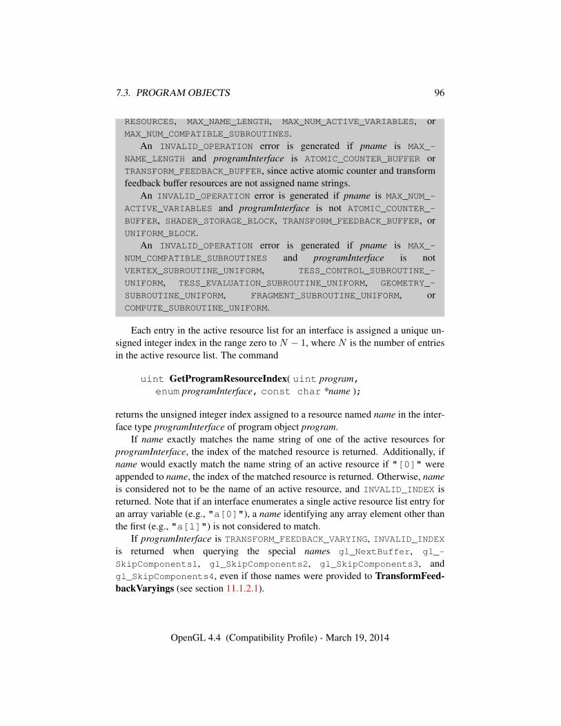
7.3. PROGRAM OBJECTS 96
RESOURCES, MAX_NAME_LENGTH, MAX_NUM_ACTIVE_VARIABLES, orMAX_NUM_COMPATIBLE_SUBROUTINES.
An INVALID_OPERATION error is generated if pname is MAX_-
NAME_LENGTH and programInterface is ATOMIC_COUNTER_BUFFER orTRANSFORM_FEEDBACK_BUFFER, since active atomic counter and transformfeedback buffer resources are not assigned name strings.
An INVALID_OPERATION error is generated if pname is MAX_NUM_-
ACTIVE_VARIABLES and programInterface is not ATOMIC_COUNTER_-
BUFFER, SHADER_STORAGE_BLOCK, TRANSFORM_FEEDBACK_BUFFER, orUNIFORM_BLOCK.
An INVALID_OPERATION error is generated if pname is MAX_-
NUM_COMPATIBLE_SUBROUTINES and programInterface is notVERTEX_SUBROUTINE_UNIFORM, TESS_CONTROL_SUBROUTINE_-
UNIFORM, TESS_EVALUATION_SUBROUTINE_UNIFORM, GEOMETRY_-
SUBROUTINE_UNIFORM, FRAGMENT_SUBROUTINE_UNIFORM, orCOMPUTE_SUBROUTINE_UNIFORM.
Each entry in the active resource list for an interface is assigned a unique un-signed integer index in the range zero to N − 1, where N is the number of entriesin the active resource list. The command
uint GetProgramResourceIndex( uint program,enum programInterface, const char *name );
returns the unsigned integer index assigned to a resource named name in the inter-face type programInterface of program object program.
If name exactly matches the name string of one of the active resources forprogramInterface, the index of the matched resource is returned. Additionally, ifname would exactly match the name string of an active resource if "[0]" wereappended to name, the index of the matched resource is returned. Otherwise, nameis considered not to be the name of an active resource, and INVALID_INDEX isreturned. Note that if an interface enumerates a single active resource list entry foran array variable (e.g., "a[0]"), a name identifying any array element other thanthe first (e.g., "a[1]") is not considered to match.
If programInterface is TRANSFORM_FEEDBACK_VARYING, INVALID_INDEXis returned when querying the special names gl_NextBuffer, gl_-
SkipComponents1, gl_SkipComponents2, gl_SkipComponents3, andgl_SkipComponents4, even if those names were provided to TransformFeed-backVaryings (see section 11.1.2.1).
OpenGL 4.4 (Compatibility Profile) - March 19, 2014
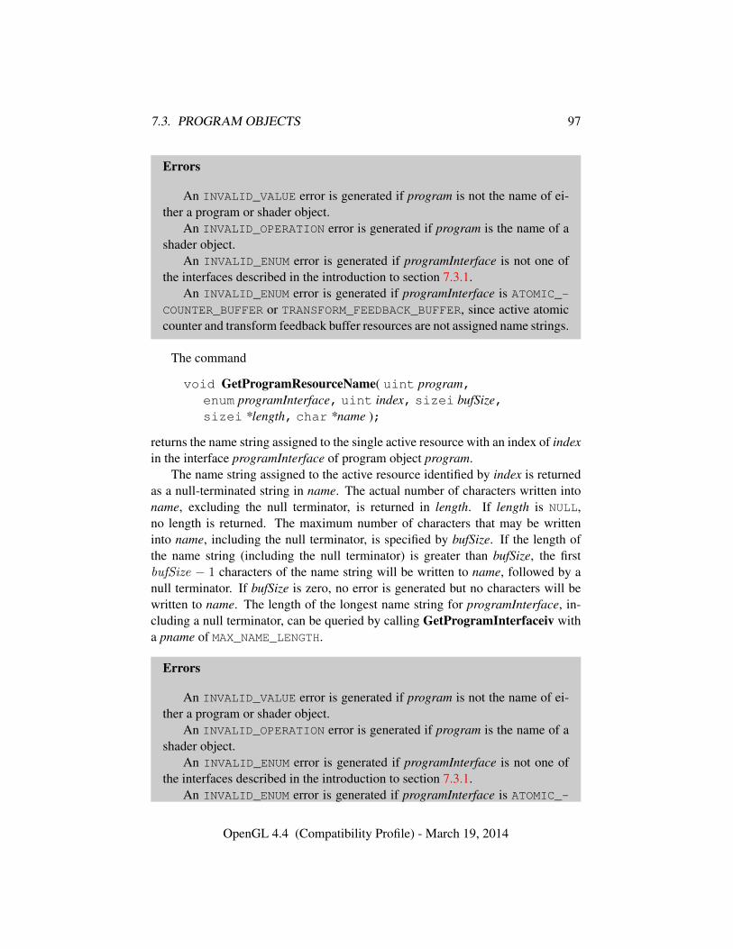
7.3. PROGRAM OBJECTS 97
Errors
An INVALID_VALUE error is generated if program is not the name of ei-ther a program or shader object.
An INVALID_OPERATION error is generated if program is the name of ashader object.
An INVALID_ENUM error is generated if programInterface is not one ofthe interfaces described in the introduction to section 7.3.1.
An INVALID_ENUM error is generated if programInterface is ATOMIC_-COUNTER_BUFFER or TRANSFORM_FEEDBACK_BUFFER, since active atomiccounter and transform feedback buffer resources are not assigned name strings.
The command
void GetProgramResourceName( uint program,enum programInterface, uint index, sizei bufSize,sizei *length, char *name );
returns the name string assigned to the single active resource with an index of indexin the interface programInterface of program object program.
The name string assigned to the active resource identified by index is returnedas a null-terminated string in name. The actual number of characters written intoname, excluding the null terminator, is returned in length. If length is NULL,no length is returned. The maximum number of characters that may be writteninto name, including the null terminator, is specified by bufSize. If the length ofthe name string (including the null terminator) is greater than bufSize, the firstbufSize − 1 characters of the name string will be written to name, followed by anull terminator. If bufSize is zero, no error is generated but no characters will bewritten to name. The length of the longest name string for programInterface, in-cluding a null terminator, can be queried by calling GetProgramInterfaceiv witha pname of MAX_NAME_LENGTH.
Errors
An INVALID_VALUE error is generated if program is not the name of ei-ther a program or shader object.
An INVALID_OPERATION error is generated if program is the name of ashader object.
An INVALID_ENUM error is generated if programInterface is not one ofthe interfaces described in the introduction to section 7.3.1.
An INVALID_ENUM error is generated if programInterface is ATOMIC_-
OpenGL 4.4 (Compatibility Profile) - March 19, 2014
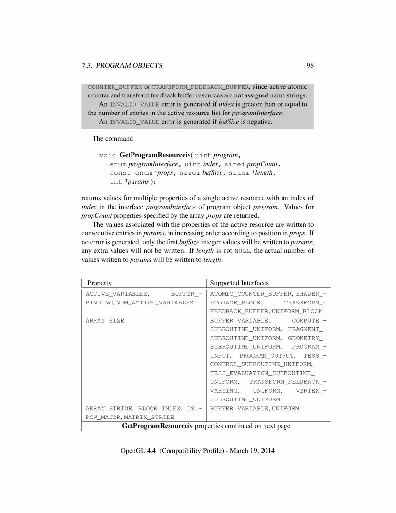
7.3. PROGRAM OBJECTS 98
COUNTER_BUFFER or TRANSFORM_FEEDBACK_BUFFER, since active atomiccounter and transform feedback buffer resources are not assigned name strings.
An INVALID_VALUE error is generated if index is greater than or equal tothe number of entries in the active resource list for programInterface.
An INVALID_VALUE error is generated if bufSize is negative.
The command
void GetProgramResourceiv( uint program,enum programInterface, uint index, sizei propCount,const enum *props, sizei bufSize, sizei *length,int *params );
returns values for multiple properties of a single active resource with an index ofindex in the interface programInterface of program object program. Values forpropCount properties specified by the array props are returned.
The values associated with the properties of the active resource are written toconsecutive entries in params, in increasing order according to position in props. Ifno error is generated, only the first bufSize integer values will be written to params;any extra values will not be written. If length is not NULL, the actual number ofvalues written to params will be written to length.
Property Supported InterfacesACTIVE_VARIABLES, BUFFER_-
BINDING, NUM_ACTIVE_VARIABLESATOMIC_COUNTER_BUFFER, SHADER_-STORAGE_BLOCK, TRANSFORM_-
FEEDBACK_BUFFER, UNIFORM_BLOCKARRAY_SIZE BUFFER_VARIABLE, COMPUTE_-
SUBROUTINE_UNIFORM, FRAGMENT_-
SUBROUTINE_UNIFORM, GEOMETRY_-
SUBROUTINE_UNIFORM, PROGRAM_-
INPUT, PROGRAM_OUTPUT, TESS_-
CONTROL_SUBROUTINE_UNIFORM,TESS_EVALUATION_SUBROUTINE_-
UNIFORM, TRANSFORM_FEEDBACK_-
VARYING, UNIFORM, VERTEX_-
SUBROUTINE_UNIFORM
ARRAY_STRIDE, BLOCK_INDEX, IS_-
ROW_MAJOR, MATRIX_STRIDEBUFFER_VARIABLE, UNIFORM
GetProgramResourceiv properties continued on next page
OpenGL 4.4 (Compatibility Profile) - March 19, 2014
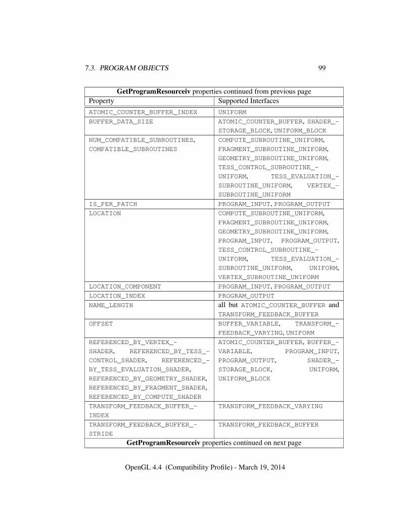
7.3. PROGRAM OBJECTS 99
GetProgramResourceiv properties continued from previous pageProperty Supported InterfacesATOMIC_COUNTER_BUFFER_INDEX UNIFORM
BUFFER_DATA_SIZE ATOMIC_COUNTER_BUFFER, SHADER_-STORAGE_BLOCK, UNIFORM_BLOCK
NUM_COMPATIBLE_SUBROUTINES,COMPATIBLE_SUBROUTINES
COMPUTE_SUBROUTINE_UNIFORM,FRAGMENT_SUBROUTINE_UNIFORM,GEOMETRY_SUBROUTINE_UNIFORM,TESS_CONTROL_SUBROUTINE_-
UNIFORM, TESS_EVALUATION_-
SUBROUTINE_UNIFORM, VERTEX_-
SUBROUTINE_UNIFORM
IS_PER_PATCH PROGRAM_INPUT, PROGRAM_OUTPUTLOCATION COMPUTE_SUBROUTINE_UNIFORM,
FRAGMENT_SUBROUTINE_UNIFORM,GEOMETRY_SUBROUTINE_UNIFORM,PROGRAM_INPUT, PROGRAM_OUTPUT,TESS_CONTROL_SUBROUTINE_-
UNIFORM, TESS_EVALUATION_-
SUBROUTINE_UNIFORM, UNIFORM,VERTEX_SUBROUTINE_UNIFORM
LOCATION_COMPONENT PROGRAM_INPUT, PROGRAM_OUTPUTLOCATION_INDEX PROGRAM_OUTPUT
NAME_LENGTH all but ATOMIC_COUNTER_BUFFER andTRANSFORM_FEEDBACK_BUFFER
OFFSET BUFFER_VARIABLE, TRANSFORM_-
FEEDBACK_VARYING, UNIFORMREFERENCED_BY_VERTEX_-
SHADER, REFERENCED_BY_TESS_-
CONTROL_SHADER, REFERENCED_-
BY_TESS_EVALUATION_SHADER,REFERENCED_BY_GEOMETRY_SHADER,REFERENCED_BY_FRAGMENT_SHADER,REFERENCED_BY_COMPUTE_SHADER
ATOMIC_COUNTER_BUFFER, BUFFER_-VARIABLE, PROGRAM_INPUT,PROGRAM_OUTPUT, SHADER_-
STORAGE_BLOCK, UNIFORM,UNIFORM_BLOCK
TRANSFORM_FEEDBACK_BUFFER_-
INDEX
TRANSFORM_FEEDBACK_VARYING
TRANSFORM_FEEDBACK_BUFFER_-
STRIDE
TRANSFORM_FEEDBACK_BUFFER
GetProgramResourceiv properties continued on next page
OpenGL 4.4 (Compatibility Profile) - March 19, 2014
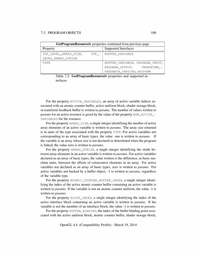
7.3. PROGRAM OBJECTS 100
GetProgramResourceiv properties continued from previous pageProperty Supported InterfacesTOP_LEVEL_ARRAY_SIZE, TOP_-
LEVEL_ARRAY_STRIDE
BUFFER_VARIABLE
TYPE BUFFER_VARIABLE, PROGRAM_INPUT,PROGRAM_OUTPUT, TRANSFORM_-
FEEDBACK_VARYING, UNIFORMTable 7.2: GetProgramResourceiv properties and supported in-terfaces
For the property ACTIVE_VARIABLES, an array of active variable indices as-sociated with an atomic counter buffer, active uniform block, shader storage block,or transform feedback buffer is written to params. The number of values written toparams for an active resource is given by the value of the property NUM_ACTIVE_-VARIABLES for the resource.
For the property ARRAY_SIZE, a single integer identifying the number of activearray elements of an active variable is written to params. The array size returnedis in units of the type associated with the property TYPE. For active variables notcorresponding to an array of basic types, the value one is written to params. Ifthe variable is an array whose size is not declared or determined when the programis linked, the value zero is written to params.
For the property ARRAY_STRIDE, a single integer identifying the stride be-tween array elements in an active variable is written to params. For active variablesdeclared as an array of basic types, the value written is the difference, in basic ma-chine units, between the offsets of consecutive elements in an array. For activevariables not declared as an array of basic types, zero is written to params. Foractive variables not backed by a buffer object, -1 is written to params, regardlessof the variable type.
For the property ATOMIC_COUNTER_BUFFER_INDEX, a single integer identi-fying the index of the active atomic counter buffer containing an active variable iswritten to params. If the variable is not an atomic counter uniform, the value -1 iswritten to params.
For the property BLOCK_INDEX, a single integer identifying the index of theactive interface block containing an active variable is written to params. If thevariable is not the member of an interface block, the value -1 is written to params.
For the property BUFFER_BINDING, the index of the buffer binding point asso-ciated with the active uniform block, atomic counter buffer, shader storage block,
OpenGL 4.4 (Compatibility Profile) - March 19, 2014
7.3. PROGRAM OBJECTS 101
or transform feedback buffer is written to params.For the property BUFFER_DATA_SIZE, the implementation-dependent mini-
mum total buffer object size is written to params. This value is the size, in basicmachine units, required to hold all active variables associated with an active uni-form block, shader storage block, or atomic counter buffer. If the final member ofan active shader storage block is an array with no declared size, the minimum buffersize is computed assuming the array was declared as an array with one element.
For the property IS_PER_PATCH, a single integer identifying whether the inputor output is a per-patch attribute is written to params. If the active variable is aper-patch attribute (declared with the patch qualifier), the value one is written toparams; otherwise, the value zero is written to params.
For the property IS_ROW_MAJOR, a single integer identifying whether an activevariable is a row-major matrix is written to params. For active variables backed bya buffer object, declared as a single matrix or array of matrices, and stored in row-major order, one is written to params. For all other active variables, zero is writtento params.
For the property LOCATION, a single integer identifying the assigned locationfor an active uniform, input, output, or subroutine uniform variable is written toparams. For input, output, or uniform variables with locations specified by alayout qualifier, the specified location is used. For vertex shader input, frag-ment shader output, or uniform variables without a layout qualifier, the locationassigned when a program is linked is written to params. For all other input andoutput variables, the value -1 is written to params. For atomic counter uniformsand uniforms in uniform blocks, the value -1 is written to params.
For the property LOCATION_COMPONENT, a single integer indicating the firstcomponent of the location assigned to an active input or output variable is writ-ten to params. For input and output variables with a component specified by alayout qualifier, the specified component is written. For all other input and outputvariables, the value zero is written.
For the property LOCATION_INDEX, a single integer identifying the fragmentcolor index of an active fragment shader output variable is written to params. If theactive variable is not an output for a fragment shader, the value -1 will be writtento params.
For the property MATRIX_STRIDE, a single integer identifying the stride be-tween columns of a column-major matrix or rows of a row-major matrix is writtento params. For active variables declared a single matrix or array of matrices, thevalue written is the difference, in basic machine units, between the offsets of con-secutive columns or rows in each matrix. For active variables not declared as amatrix or array of matrices, zero is written to params. For active variables notbacked by a buffer object, -1 is written to params, regardless of the variable type.
OpenGL 4.4 (Compatibility Profile) - March 19, 2014
7.3. PROGRAM OBJECTS 102
For the property NAME_LENGTH, a single integer identifying the length of thename string associated with an active variable, interface block, or subroutine iswritten to params. The name length includes a terminating null character.
For the property NUM_ACTIVE_VARIABLES, the number of active variables as-sociated with an active uniform block, atomic counter buffer, shader storage block,or transform feedback buffer is written to params.
For the property OFFSET, a single integer identifying the offset of an ac-tive variable is written to params. For variables in the BUFFER_VARIABLE
and UNIFORM interfaces that are backed by a buffer object, the value writtenis the offset of that variable relative to the base of the buffer range holdingits value. For variables in the TRANSFORM_FEEDBACK_VARYING interface, thevalue written is the offset in the transform feedback buffer storage assigned toeach vertex captured in transform feedback mode where the value of the vari-able will be stored. Such offsets are specified via the xfb_offset layout qual-ifier or assigned according to the variables position in the list of strings passedto TransformFeedbackVaryings. Offsets are expressed in basic machine units.For all variables not recorded in transform feedback mode, including the spe-cial names gl_NextBuffer, gl_SkipComponents1, gl_SkipComponents2,gl_SkipComponents3, and gl_SkipComponents4, -1 is written to params.
For the properties REFERENCED_BY_VERTEX_SHADER, REFERENCED_-
BY_TESS_CONTROL_SHADER, REFERENCED_BY_TESS_EVALUATION_SHADER,REFERENCED_BY_GEOMETRY_SHADER, REFERENCED_BY_FRAGMENT_SHADER,and REFERENCED_BY_COMPUTE_SHADER, a single integer is written to params,identifying whether the active resource is referenced by the vertex, tessellation con-trol, tessellation evaluation, geometry, fragment, or compute shaders, respectively,in the program object. The value one is written to params if an active variable isreferenced by the corresponding shader, or if an active uniform block, shader stor-age block, or atomic counter buffer contains at least one variable referenced by thecorresponding shader. Otherwise, the value zero is written to params.
For the property TOP_LEVEL_ARRAY_SIZE, a single integer identifying thenumber of active array elements of the top-level shader storage block member con-taining to the active variable is written to params. If the top-level block member isnot declared as an array, the value one is written to params. If the top-level blockmember is an array whose size is not declared or determined when the program islinked, the value zero is written to params.
For the property TOP_LEVEL_ARRAY_STRIDE, a single integer identifying thestride between array elements of the top-level shader storage block member con-taining the active variable is written to params. For top-level block members de-clared as arrays, the value written is the difference, in basic machine units, betweenthe offsets of the active variable for consecutive elements in the top-level array. For
OpenGL 4.4 (Compatibility Profile) - March 19, 2014
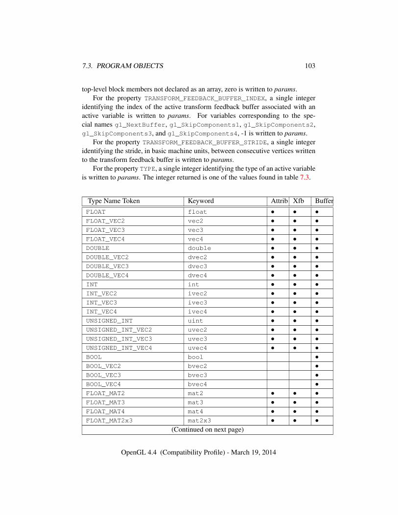
7.3. PROGRAM OBJECTS 103
top-level block members not declared as an array, zero is written to params.For the property TRANSFORM_FEEDBACK_BUFFER_INDEX, a single integer
identifying the index of the active transform feedback buffer associated with anactive variable is written to params. For variables corresponding to the spe-cial names gl_NextBuffer, gl_SkipComponents1, gl_SkipComponents2,gl_SkipComponents3, and gl_SkipComponents4, -1 is written to params.
For the property TRANSFORM_FEEDBACK_BUFFER_STRIDE, a single integeridentifying the stride, in basic machine units, between consecutive vertices writtento the transform feedback buffer is written to params.
For the property TYPE, a single integer identifying the type of an active variableis written to params. The integer returned is one of the values found in table 7.3.
Type Name Token Keyword Attrib Xfb BufferFLOAT float • • •FLOAT_VEC2 vec2 • • •FLOAT_VEC3 vec3 • • •FLOAT_VEC4 vec4 • • •DOUBLE double • • •DOUBLE_VEC2 dvec2 • • •DOUBLE_VEC3 dvec3 • • •DOUBLE_VEC4 dvec4 • • •INT int • • •INT_VEC2 ivec2 • • •INT_VEC3 ivec3 • • •INT_VEC4 ivec4 • • •UNSIGNED_INT uint • • •UNSIGNED_INT_VEC2 uvec2 • • •UNSIGNED_INT_VEC3 uvec3 • • •UNSIGNED_INT_VEC4 uvec4 • • •BOOL bool •BOOL_VEC2 bvec2 •BOOL_VEC3 bvec3 •BOOL_VEC4 bvec4 •FLOAT_MAT2 mat2 • • •FLOAT_MAT3 mat3 • • •FLOAT_MAT4 mat4 • • •FLOAT_MAT2x3 mat2x3 • • •
(Continued on next page)
OpenGL 4.4 (Compatibility Profile) - March 19, 2014
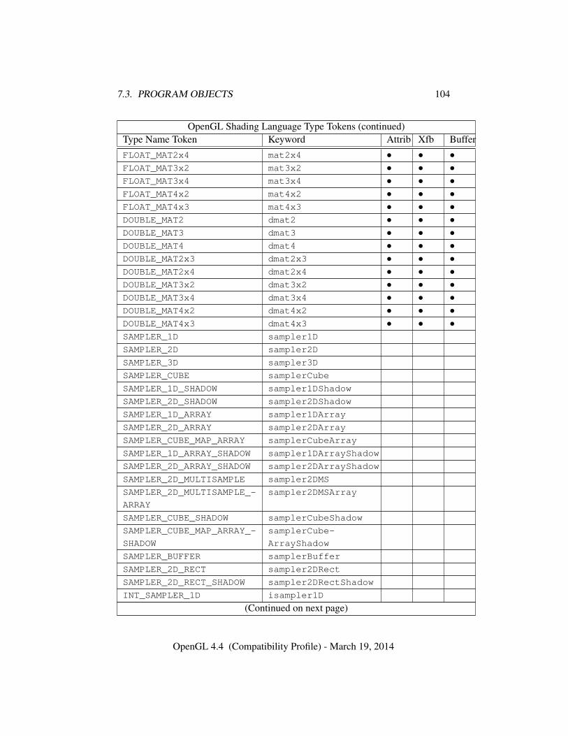
7.3. PROGRAM OBJECTS 104
OpenGL Shading Language Type Tokens (continued)Type Name Token Keyword Attrib Xfb BufferFLOAT_MAT2x4 mat2x4 • • •FLOAT_MAT3x2 mat3x2 • • •FLOAT_MAT3x4 mat3x4 • • •FLOAT_MAT4x2 mat4x2 • • •FLOAT_MAT4x3 mat4x3 • • •DOUBLE_MAT2 dmat2 • • •DOUBLE_MAT3 dmat3 • • •DOUBLE_MAT4 dmat4 • • •DOUBLE_MAT2x3 dmat2x3 • • •DOUBLE_MAT2x4 dmat2x4 • • •DOUBLE_MAT3x2 dmat3x2 • • •DOUBLE_MAT3x4 dmat3x4 • • •DOUBLE_MAT4x2 dmat4x2 • • •DOUBLE_MAT4x3 dmat4x3 • • •SAMPLER_1D sampler1D
SAMPLER_2D sampler2D
SAMPLER_3D sampler3D
SAMPLER_CUBE samplerCube
SAMPLER_1D_SHADOW sampler1DShadow
SAMPLER_2D_SHADOW sampler2DShadow
SAMPLER_1D_ARRAY sampler1DArray
SAMPLER_2D_ARRAY sampler2DArray
SAMPLER_CUBE_MAP_ARRAY samplerCubeArray
SAMPLER_1D_ARRAY_SHADOW sampler1DArrayShadow
SAMPLER_2D_ARRAY_SHADOW sampler2DArrayShadow
SAMPLER_2D_MULTISAMPLE sampler2DMS
SAMPLER_2D_MULTISAMPLE_-
ARRAY
sampler2DMSArray
SAMPLER_CUBE_SHADOW samplerCubeShadow
SAMPLER_CUBE_MAP_ARRAY_-
SHADOW
samplerCube-
ArrayShadow
SAMPLER_BUFFER samplerBuffer
SAMPLER_2D_RECT sampler2DRect
SAMPLER_2D_RECT_SHADOW sampler2DRectShadow
INT_SAMPLER_1D isampler1D
(Continued on next page)
OpenGL 4.4 (Compatibility Profile) - March 19, 2014
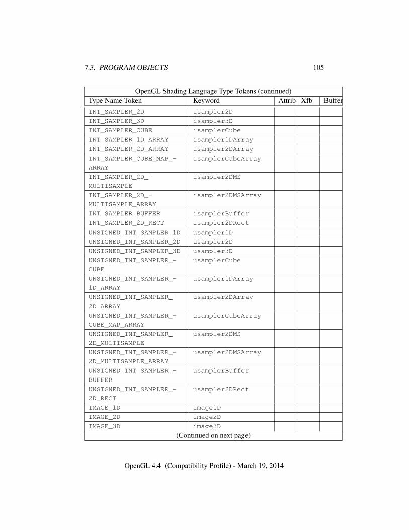
7.3. PROGRAM OBJECTS 105
OpenGL Shading Language Type Tokens (continued)Type Name Token Keyword Attrib Xfb BufferINT_SAMPLER_2D isampler2D
INT_SAMPLER_3D isampler3D
INT_SAMPLER_CUBE isamplerCube
INT_SAMPLER_1D_ARRAY isampler1DArray
INT_SAMPLER_2D_ARRAY isampler2DArray
INT_SAMPLER_CUBE_MAP_-
ARRAY
isamplerCubeArray
INT_SAMPLER_2D_-
MULTISAMPLE
isampler2DMS
INT_SAMPLER_2D_-
MULTISAMPLE_ARRAY
isampler2DMSArray
INT_SAMPLER_BUFFER isamplerBuffer
INT_SAMPLER_2D_RECT isampler2DRect
UNSIGNED_INT_SAMPLER_1D usampler1D
UNSIGNED_INT_SAMPLER_2D usampler2D
UNSIGNED_INT_SAMPLER_3D usampler3D
UNSIGNED_INT_SAMPLER_-
CUBE
usamplerCube
UNSIGNED_INT_SAMPLER_-
1D_ARRAY
usampler1DArray
UNSIGNED_INT_SAMPLER_-
2D_ARRAY
usampler2DArray
UNSIGNED_INT_SAMPLER_-
CUBE_MAP_ARRAY
usamplerCubeArray
UNSIGNED_INT_SAMPLER_-
2D_MULTISAMPLE
usampler2DMS
UNSIGNED_INT_SAMPLER_-
2D_MULTISAMPLE_ARRAY
usampler2DMSArray
UNSIGNED_INT_SAMPLER_-
BUFFER
usamplerBuffer
UNSIGNED_INT_SAMPLER_-
2D_RECT
usampler2DRect
IMAGE_1D image1D
IMAGE_2D image2D
IMAGE_3D image3D
(Continued on next page)
OpenGL 4.4 (Compatibility Profile) - March 19, 2014
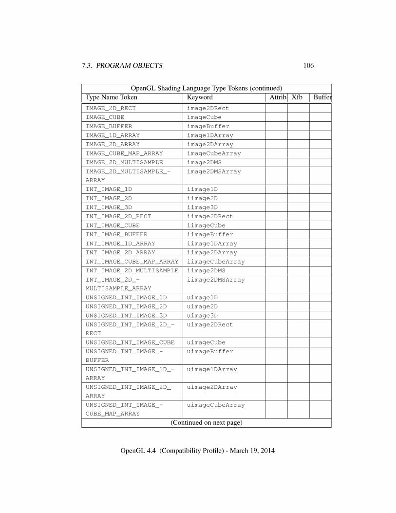
7.3. PROGRAM OBJECTS 106
OpenGL Shading Language Type Tokens (continued)Type Name Token Keyword Attrib Xfb BufferIMAGE_2D_RECT image2DRect
IMAGE_CUBE imageCube
IMAGE_BUFFER imageBuffer
IMAGE_1D_ARRAY image1DArray
IMAGE_2D_ARRAY image2DArray
IMAGE_CUBE_MAP_ARRAY imageCubeArray
IMAGE_2D_MULTISAMPLE image2DMS
IMAGE_2D_MULTISAMPLE_-
ARRAY
image2DMSArray
INT_IMAGE_1D iimage1D
INT_IMAGE_2D iimage2D
INT_IMAGE_3D iimage3D
INT_IMAGE_2D_RECT iimage2DRect
INT_IMAGE_CUBE iimageCube
INT_IMAGE_BUFFER iimageBuffer
INT_IMAGE_1D_ARRAY iimage1DArray
INT_IMAGE_2D_ARRAY iimage2DArray
INT_IMAGE_CUBE_MAP_ARRAY iimageCubeArray
INT_IMAGE_2D_MULTISAMPLE iimage2DMS
INT_IMAGE_2D_-
MULTISAMPLE_ARRAY
iimage2DMSArray
UNSIGNED_INT_IMAGE_1D uimage1D
UNSIGNED_INT_IMAGE_2D uimage2D
UNSIGNED_INT_IMAGE_3D uimage3D
UNSIGNED_INT_IMAGE_2D_-
RECT
uimage2DRect
UNSIGNED_INT_IMAGE_CUBE uimageCube
UNSIGNED_INT_IMAGE_-
BUFFER
uimageBuffer
UNSIGNED_INT_IMAGE_1D_-
ARRAY
uimage1DArray
UNSIGNED_INT_IMAGE_2D_-
ARRAY
uimage2DArray
UNSIGNED_INT_IMAGE_-
CUBE_MAP_ARRAY
uimageCubeArray
(Continued on next page)
OpenGL 4.4 (Compatibility Profile) - March 19, 2014
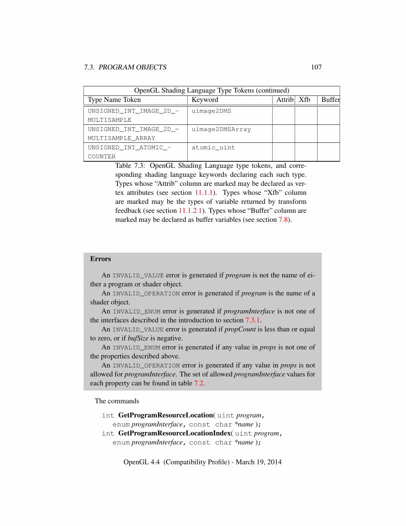
7.3. PROGRAM OBJECTS 107
OpenGL Shading Language Type Tokens (continued)Type Name Token Keyword Attrib Xfb BufferUNSIGNED_INT_IMAGE_2D_-
MULTISAMPLE
uimage2DMS
UNSIGNED_INT_IMAGE_2D_-
MULTISAMPLE_ARRAY
uimage2DMSArray
UNSIGNED_INT_ATOMIC_-
COUNTER
atomic_uint
Table 7.3: OpenGL Shading Language type tokens, and corre-sponding shading language keywords declaring each such type.Types whose “Attrib” column are marked may be declared as ver-tex attributes (see section 11.1.1). Types whose “Xfb” columnare marked may be the types of variable returned by transformfeedback (see section 11.1.2.1). Types whose “Buffer” column aremarked may be declared as buffer variables (see section 7.8).
Errors
An INVALID_VALUE error is generated if program is not the name of ei-ther a program or shader object.
An INVALID_OPERATION error is generated if program is the name of ashader object.
An INVALID_ENUM error is generated if programInterface is not one ofthe interfaces described in the introduction to section 7.3.1.
An INVALID_VALUE error is generated if propCount is less than or equalto zero, or if bufSize is negative.
An INVALID_ENUM error is generated if any value in props is not one ofthe properties described above.
An INVALID_OPERATION error is generated if any value in props is notallowed for programInterface. The set of allowed programInterface values foreach property can be found in table 7.2.
The commands
int GetProgramResourceLocation( uint program,enum programInterface, const char *name );
int GetProgramResourceLocationIndex( uint program,enum programInterface, const char *name );
OpenGL 4.4 (Compatibility Profile) - March 19, 2014
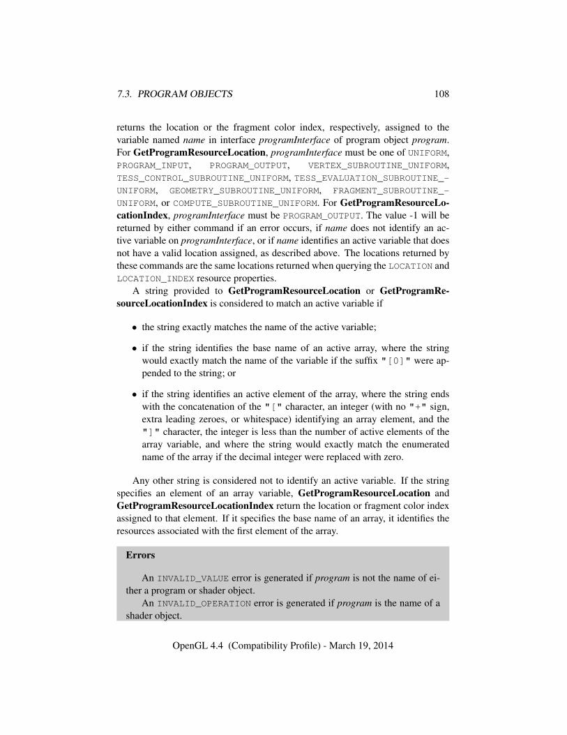
7.3. PROGRAM OBJECTS 108
returns the location or the fragment color index, respectively, assigned to thevariable named name in interface programInterface of program object program.For GetProgramResourceLocation, programInterface must be one of UNIFORM,PROGRAM_INPUT, PROGRAM_OUTPUT, VERTEX_SUBROUTINE_UNIFORM,TESS_CONTROL_SUBROUTINE_UNIFORM, TESS_EVALUATION_SUBROUTINE_-UNIFORM, GEOMETRY_SUBROUTINE_UNIFORM, FRAGMENT_SUBROUTINE_-
UNIFORM, or COMPUTE_SUBROUTINE_UNIFORM. For GetProgramResourceLo-cationIndex, programInterface must be PROGRAM_OUTPUT. The value -1 will bereturned by either command if an error occurs, if name does not identify an ac-tive variable on programInterface, or if name identifies an active variable that doesnot have a valid location assigned, as described above. The locations returned bythese commands are the same locations returned when querying the LOCATION andLOCATION_INDEX resource properties.
A string provided to GetProgramResourceLocation or GetProgramRe-sourceLocationIndex is considered to match an active variable if
• the string exactly matches the name of the active variable;
• if the string identifies the base name of an active array, where the stringwould exactly match the name of the variable if the suffix "[0]" were ap-pended to the string; or
• if the string identifies an active element of the array, where the string endswith the concatenation of the "[" character, an integer (with no "+" sign,extra leading zeroes, or whitespace) identifying an array element, and the"]" character, the integer is less than the number of active elements of thearray variable, and where the string would exactly match the enumeratedname of the array if the decimal integer were replaced with zero.
Any other string is considered not to identify an active variable. If the stringspecifies an element of an array variable, GetProgramResourceLocation andGetProgramResourceLocationIndex return the location or fragment color indexassigned to that element. If it specifies the base name of an array, it identifies theresources associated with the first element of the array.
Errors
An INVALID_VALUE error is generated if program is not the name of ei-ther a program or shader object.
An INVALID_OPERATION error is generated if program is the name of ashader object.
OpenGL 4.4 (Compatibility Profile) - March 19, 2014
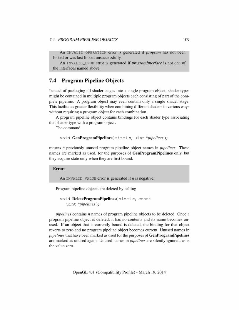
7.4. PROGRAM PIPELINE OBJECTS 109
An INVALID_OPERATION error is generated if program has not beenlinked or was last linked unsuccessfully.
An INVALID_ENUM error is generated if programInterface is not one ofthe interfaces named above.
7.4 Program Pipeline Objects
Instead of packaging all shader stages into a single program object, shader typesmight be contained in multiple program objects each consisting of part of the com-plete pipeline. A program object may even contain only a single shader stage.This facilitates greater flexibility when combining different shaders in various wayswithout requiring a program object for each combination.
A program pipeline object contains bindings for each shader type associatingthat shader type with a program object.
The command
void GenProgramPipelines( sizei n, uint *pipelines );
returns n previously unused program pipeline object names in pipelines. Thesenames are marked as used, for the purposes of GenProgramPipelines only, butthey acquire state only when they are first bound.
Errors
An INVALID_VALUE error is generated if n is negative.
Program pipeline objects are deleted by calling
void DeleteProgramPipelines( sizei n, constuint *pipelines );
pipelines contains n names of program pipeline objects to be deleted. Once aprogram pipeline object is deleted, it has no contents and its name becomes un-used. If an object that is currently bound is deleted, the binding for that objectreverts to zero and no program pipeline object becomes current. Unused names inpipelines that have been marked as used for the purposes of GenProgramPipelinesare marked as unused again. Unused names in pipelines are silently ignored, as isthe value zero.
OpenGL 4.4 (Compatibility Profile) - March 19, 2014
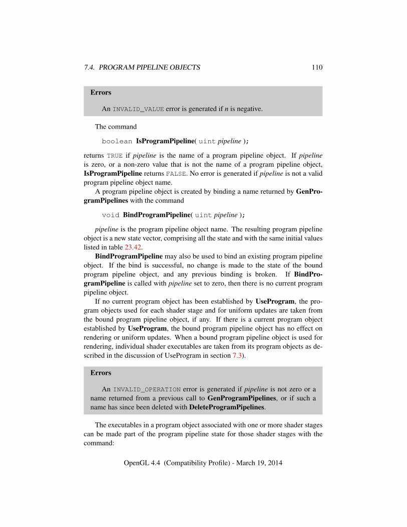
7.4. PROGRAM PIPELINE OBJECTS 110
Errors
An INVALID_VALUE error is generated if n is negative.
The command
boolean IsProgramPipeline( uint pipeline );
returns TRUE if pipeline is the name of a program pipeline object. If pipelineis zero, or a non-zero value that is not the name of a program pipeline object,IsProgramPipeline returns FALSE. No error is generated if pipeline is not a validprogram pipeline object name.
A program pipeline object is created by binding a name returned by GenPro-gramPipelines with the command
void BindProgramPipeline( uint pipeline );
pipeline is the program pipeline object name. The resulting program pipelineobject is a new state vector, comprising all the state and with the same initial valueslisted in table 23.42.
BindProgramPipeline may also be used to bind an existing program pipelineobject. If the bind is successful, no change is made to the state of the boundprogram pipeline object, and any previous binding is broken. If BindPro-gramPipeline is called with pipeline set to zero, then there is no current programpipeline object.
If no current program object has been established by UseProgram, the pro-gram objects used for each shader stage and for uniform updates are taken fromthe bound program pipeline object, if any. If there is a current program objectestablished by UseProgram, the bound program pipeline object has no effect onrendering or uniform updates. When a bound program pipeline object is used forrendering, individual shader executables are taken from its program objects as de-scribed in the discussion of UseProgram in section 7.3).
Errors
An INVALID_OPERATION error is generated if pipeline is not zero or aname returned from a previous call to GenProgramPipelines, or if such aname has since been deleted with DeleteProgramPipelines.
The executables in a program object associated with one or more shader stagescan be made part of the program pipeline state for those shader stages with thecommand:
OpenGL 4.4 (Compatibility Profile) - March 19, 2014
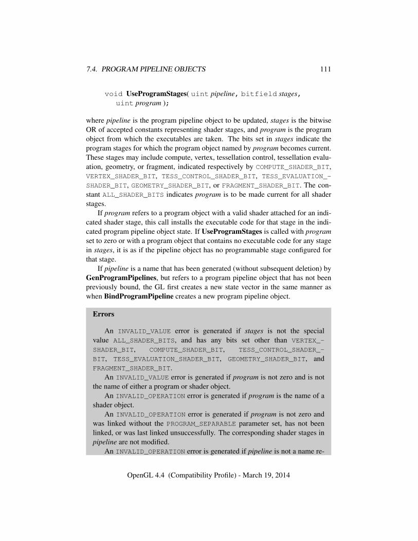
7.4. PROGRAM PIPELINE OBJECTS 111
void UseProgramStages( uint pipeline, bitfield stages,uint program );
where pipeline is the program pipeline object to be updated, stages is the bitwiseOR of accepted constants representing shader stages, and program is the programobject from which the executables are taken. The bits set in stages indicate theprogram stages for which the program object named by program becomes current.These stages may include compute, vertex, tessellation control, tessellation evalu-ation, geometry, or fragment, indicated respectively by COMPUTE_SHADER_BIT,VERTEX_SHADER_BIT, TESS_CONTROL_SHADER_BIT, TESS_EVALUATION_-
SHADER_BIT, GEOMETRY_SHADER_BIT, or FRAGMENT_SHADER_BIT. The con-stant ALL_SHADER_BITS indicates program is to be made current for all shaderstages.
If program refers to a program object with a valid shader attached for an indi-cated shader stage, this call installs the executable code for that stage in the indi-cated program pipeline object state. If UseProgramStages is called with programset to zero or with a program object that contains no executable code for any stagein stages, it is as if the pipeline object has no programmable stage configured forthat stage.
If pipeline is a name that has been generated (without subsequent deletion) byGenProgramPipelines, but refers to a program pipeline object that has not beenpreviously bound, the GL first creates a new state vector in the same manner aswhen BindProgramPipeline creates a new program pipeline object.
Errors
An INVALID_VALUE error is generated if stages is not the specialvalue ALL_SHADER_BITS, and has any bits set other than VERTEX_-
SHADER_BIT, COMPUTE_SHADER_BIT, TESS_CONTROL_SHADER_-
BIT, TESS_EVALUATION_SHADER_BIT, GEOMETRY_SHADER_BIT, andFRAGMENT_SHADER_BIT.
An INVALID_VALUE error is generated if program is not zero and is notthe name of either a program or shader object.
An INVALID_OPERATION error is generated if program is the name of ashader object.
An INVALID_OPERATION error is generated if program is not zero andwas linked without the PROGRAM_SEPARABLE parameter set, has not beenlinked, or was last linked unsuccessfully. The corresponding shader stages inpipeline are not modified.
An INVALID_OPERATION error is generated if pipeline is not a name re-
OpenGL 4.4 (Compatibility Profile) - March 19, 2014
7.4. PROGRAM PIPELINE OBJECTS 112
turned from a previous call to GenProgramPipelines or if such a name hassince been deleted by DeleteProgramPipelines.
The command
void ActiveShaderProgram( uint pipeline, uint program );
sets the linked program named by program to be the active program (see sec-tion 7.6.1) used for uniform updates for the program pipeline object pipeline. Ifprogram is zero, then it is as if there is no active program for pipeline.
If pipeline is a name that has been generated (without subsequent deletion) byGenProgramPipelines, but refers to a program pipeline object that has not beenpreviously bound, the GL first creates a new state vector in the same manner aswhen BindProgramPipeline creates a new program pipeline object.
Errors
An INVALID_OPERATION error is generated if pipeline is not a name re-turned from a previous call to GenProgramPipelines or if such a name hassince been deleted by DeleteProgramPipelines.
An INVALID_VALUE error is generated if program is not zero and is notthe name of either a program or shader object.
An INVALID_OPERATION error is generated if program is the name of ashader object.
An INVALID_OPERATION error is generated if program is not zero andhas not been linked, or was last linked unsuccessfully. The active program isnot modified.
7.4.1 Shader Interface Matching
When multiple shader stages are active, the outputs of one stage form an interfacewith the inputs of the next stage. At each such interface, shader inputs are matchedup against outputs from the previous stage:
• An output block is considered to match an input block in the subsequentshader if the two blocks have the same block name, and the members of theblock match exactly in name, type, qualification, and declaration order.
• An output variable is considered to match an input variable in the subsequentshader if:
– the two variables match in name, type, and qualification; or
OpenGL 4.4 (Compatibility Profile) - March 19, 2014
7.4. PROGRAM PIPELINE OBJECTS 113
– the two variables are declared with the same location andcomponent layout qualifiers and match in type and qualification.
For the purposes of interface matching, variables declared with a location
layout qualifier but without a component layout qualifier are considered tohave declared a component layout qualifier of zero. Variables or block mem-bers declared as structures are considered to match in type if and only if structuremembers match in name, type, qualification, and declaration order. Variables orblock members declared as arrays are considered to match in type only if bothdeclarations specify the same element type and array size. The rules for determin-ing if variables or block members match in qualification are found in the OpenGLShading Language Specification.
Tessellation control shader per-vertex output variables and blocks and tessella-tion control, tessellation evaluation, and geometry shader per-vertex input variablesand blocks are required to be declared as arrays, with each element representinginput or output values for a single vertex of a multi-vertex primitive. For the pur-poses of interface matching, such variables and blocks are treated as though theywere not declared as arrays.
For program objects containing multiple shaders, LinkProgram will check formismatches on interfaces between shader stages in the program being linked andgenerate a link error if a mismatch is detected. A link error is generated if any stat-ically referenced input variable or block does not have a matching output. If eithershader redeclares the built-in arrays gl_ClipDistance[] or gl_TexCoord[],the array must have the same size in both shaders. If either shader redeclares built-in input or output color variables, they must have matching interpolation qualifiers,as described in the OpenGL Shading Language Specification.
With separable program objects, interfaces between shader stages may involvethe outputs from one program object and the inputs from a second program object.For such interfaces, it is not possible to detect mismatches at link time, because theprograms are linked separately. When each such program is linked, all inputs oroutputs interfacing with another program stage are treated as active. The linker willgenerate an executable that assumes the presence of a compatible program on theother side of the interface. If a mismatch between programs occurs, no GL error isgenerated, but some or all of the inputs on the interface will be undefined.
At an interface between program objects, the set of inputs and outputs are con-sidered to match exactly if and only if:
• The built-in input and output blocks used on the interface (gl_PerVertexor gl_PerFragment) match, as described below.
OpenGL 4.4 (Compatibility Profile) - March 19, 2014
7.4. PROGRAM PIPELINE OBJECTS 114
• Every declared input block or variable must have a matching output, as de-scribed above.
• There are no output blocks or user-defined output variables declared withouta matching input block or variable declaration.
When the set of inputs and outputs on an interface between programs matchesexactly, all inputs are well-defined except when the corresponding outputs werenot written in the previous shader. However, any mismatch between inputs andoutputs results in all inputs being undefined except for cases noted below. Evenif an input has a corresponding output that matches exactly, mismatches on otherinputs or outputs may adversely affect the executable code generated to read orwrite the matching variable.
The inputs and outputs on an interface between programs need not match ex-actly when input and output location qualifiers (sections 4.4.1(“Input Layout Qual-ifiers”) and 4.4.2(“Output Layout Qualifiers”) of the OpenGL Shading LanguageSpecification) are used. When using location qualifiers, any input with an inputlocation qualifier will be well-defined as long as the other program writes to amatching output, as described above. The names of variables need not match whenmatching by location.
Additionally, scalar and vector inputs with location layout qualifiers willbe well-defined if there is a corresponding output satisfying all of the followingconditions:
• the input and output match exactly in qualification, including in thelocation layout qualifier;
• the output is a vector with the same basic component type and has morecomponents than the input; and
• the common component type of the input and output is int, uint, or float(scalars, vectors, and matrices with double component type are excluded).
In this case, the components of the input will be taken from the first componentsof the matching output, and the extra components of the output will be ignored.
To use any built-in input or output in the gl_PerVertex and gl_-
PerFragment blocks in separable program objects, shader code must redeclarethose blocks prior to use. A separable program will fail to link if:
• it contains multiple shaders of a single type with different redeclarations ofthese built-in input and output blocks; or
OpenGL 4.4 (Compatibility Profile) - March 19, 2014
7.4. PROGRAM PIPELINE OBJECTS 115
• any shader uses a built-in block member not found in the redeclaration ofthat block.
There is one exception to this rule described below.As described above, an exact interface match requires matching built-in input
and output blocks. At an interface between two non-fragment shader stages, thegl_PerVertex input and output blocks are considered to match if and only if theblock members members match exactly in name, type, qualification, and declara-tion order. At an interface involving the fragment shader stage, a gl_PerVertexoutput block is considered to match a gl_PerFragment input block if all of thefollowing conditions apply:
• the gl_PerVertex block includes either gl_FrontColor or gl_-
BackColor if and only if the gl_PerFragment block includes gl_Color;
• the gl_PerVertex block includes either gl_FrontSecondaryColor orgl_BackSecondaryColor if and only if the gl_PerFragment block in-cludes gl_SecondaryColor;
• the gl_PerVertex block includes gl_FogFragCoord if and only if thegl_PerFragment block also includes gl_FogFragCoord; and
• the size of gl_TexCoord[] in gl_PerVertex and gl_PerFragment isidentical.
At an interface between gl_PerVertex outputs and gl_PerFragment in-puts, the presence or absence of any block members other than those listed imme-diately above does not affect interface matching.
Built-in inputs or outputs not found in blocks do not affect interface match-ing. Any such built-in inputs are well-defined unless they are derived from built-inoutputs not written by the previous shader stage.
7.4.2 Program Pipeline Object State
The state required to support program pipeline objects consists of a single bindingname of the current program pipeline object. This binding is initially zero indicat-ing no program pipeline object is bound.
The state of each program pipeline object consists of:
• Unsigned integers holding the names of the active program and each of thecurrent vertex, tessellation control, tessellation evaluation, geometry, frag-ment, and compute stage programs. Each integer is initially zero.
OpenGL 4.4 (Compatibility Profile) - March 19, 2014
7.5. PROGRAM BINARIES 116
• A boolean holding the status of the last validation attempt, initially false.
• An array of type char containing the information log (see section 7.13),initially empty.
• An integer holding the length of the information log.
7.5 Program Binaries
The command
void GetProgramBinary( uint program, sizei bufSize,sizei *length, enum *binaryFormat, void *binary );
returns a binary representation of the program object’s compiled and linked exe-cutable source, henceforth referred to as its program binary. The maximum numberof bytes that may be written into binary is specified by bufSize. The actual num-ber of bytes written into binary is returned in length and its format is returned inbinaryFormat. If length is NULL, then no length is returned.
The number of bytes in the program binary can be queried by calling GetPro-gramiv with pname PROGRAM_BINARY_LENGTH.
Errors
An INVALID_VALUE error is generated if program is not the name of ei-ther a program or shader object.
An INVALID_OPERATION error is generated if program is the name of ashader object.
An INVALID_OPERATION error is generated if program has not beenlinked, or was last linked unsuccessfully. In this case its program binary lengthis zero.
An INVALID_VALUE error is generated if bufSize is negative.An INVALID_OPERATION error is generated if bufSize is less than the
number of bytes in the program binary.
The command
void ProgramBinary( uint program, enum binaryFormat,const void *binary, sizei length );
OpenGL 4.4 (Compatibility Profile) - March 19, 2014
7.5. PROGRAM BINARIES 117
loads a program object with a program binary previously returned from GetPro-gramBinary. This is useful to avoid online compilation, while still using OpenGLShading Language source shaders as a portable initial format. binaryFormat andbinary must be those returned by a previous call to GetProgramBinary, and lengthmust be the length of the program binary as returned by GetProgramBinary orGetProgramiv with pname PROGRAM_BINARY_LENGTH. Loading the program bi-nary will fail, setting the LINK_STATUS of program to FALSE, if these conditionsare not met.
Loading a program binary may also fail if the implementation determines thatthere has been a change in hardware or software configuration from when the pro-gram binary was produced such as having been compiled with an incompatibleor outdated version of the compiler. In this case the application should fall backto providing the original OpenGL Shading Language source shaders, and perhapsagain retrieve the program binary for future use.
A program object’s program binary is replaced by calls to LinkProgram orProgramBinary. Where linking success or failure is concerned, ProgramBinarycan be considered to perform an implicit linking operation. LinkProgram andProgramBinary both set the program object’s LINK_STATUS to TRUE or FALSE,as queried with GetProgramiv, to reflect success or failure and update the infor-mation log, queried with GetProgramInfoLog, to provide details about warningsor errors.
A successful call to ProgramBinary will reset all uniform variables in thedefault uniform block, all uniform block buffer bindings, and all shader storageblock buffer bindings to their initial values. The initial value is either the valueof the variable’s initializer as specified in the original shader source, or zero if noinitializer was present.
Additionally, all vertex shader input and fragment shader output assignmentsand atomic counter binding, offset and stride assignments that were in effect whenthe program was linked before saving are restored when ProgramBinary is calledsuccessfully.
If ProgramBinary fails to load a binary, no error is generated, but any infor-mation about a previous link or load of that program object is lost. Thus, a failedload does not restore the old state of program. The failure does not alter otherprogram state not affected by linking such as the attached shaders, and the vertexattribute and fragment data location bindings as set by BindAttribLocation andBindFragDataLocation.
OpenGL defines no specific binary formats. Queries of values NUM_-
PROGRAM_BINARY_FORMATS and PROGRAM_BINARY_FORMATS return the num-ber of program binary formats and the list of program binary format values sup-ported by an implementation. The binaryFormat returned by GetProgramBinary
OpenGL 4.4 (Compatibility Profile) - March 19, 2014
7.6. UNIFORM VARIABLES 118
must be present in this list.Any program binary retrieved using GetProgramBinary and submitted using
ProgramBinary under the same configuration must be successful. Any programsloaded successfully by ProgramBinary must be run properly with any legal GLstate vector.
If an implementation needs to recompile or otherwise modify program exe-cutables based on GL state outside the program, GetProgramBinary is requiredto save enough information to allow such recompilation.
To indicate that a program binary is likely to be retrieved, ProgramParameterishould be called with pname set to PROGRAM_BINARY_RETRIEVABLE_HINT andvalue set to TRUE. This setting will not be in effect until the next time LinkPro-gram or ProgramBinary has been called successfully. Additionally, the appli-cation may defer GetProgramBinary calls until after using the program with allnon-program state vectors that it is likely to encounter. Such deferral may allowimplementations to save additional information in the program binary that wouldminimize recompilation in future uses of the program binary.
Errors
An INVALID_VALUE error is generated if program is not the name of ei-ther a program or shader object.
An INVALID_OPERATION error is generated if program is the name of ashader object.
An INVALID_ENUM error is generated if binaryFormat is not a binary for-mat present in the list of specific binary formats supported.
An INVALID_VALUE error is generated if length is negative.
7.6 Uniform Variables
Shaders can declare named uniform variables, as described in the OpenGL ShadingLanguage Specification. A uniform is considered an active uniform if the compilerand linker determine that the uniform will actually be accessed when the executablecode is executed. In cases where the compiler and linker cannot make a conclusivedetermination, the uniform will be considered active.
Sets of uniforms, except for atomic counters, images, samplers, and subroutineuniforms, can be grouped into uniform blocks.
Named uniform blocks, as described in the OpenGL Shading Language Speci-fication, store uniform values in the data store of a buffer object corresponding tothe uniform block. Such blocks are assigned a uniform block index.
OpenGL 4.4 (Compatibility Profile) - March 19, 2014
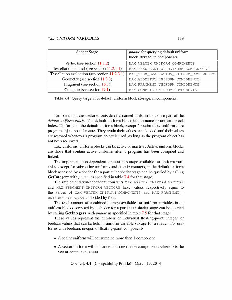
7.6. UNIFORM VARIABLES 119
Shader Stage pname for querying default uniformblock storage, in components
Vertex (see section 11.1.2) MAX_VERTEX_UNIFORM_COMPONENTS
Tessellation control (see section 11.2.1.1) MAX_TESS_CONTROL_UNIFORM_COMPONENTS
Tessellation evaluation (see section 11.2.3.1) MAX_TESS_EVALUATION_UNIFORM_COMPONENTS
Geometry (see section 11.3.3) MAX_GEOMETRY_UNIFORM_COMPONENTS
Fragment (see section 15.1) MAX_FRAGMENT_UNIFORM_COMPONENTS
Compute (see section 19.1) MAX_COMPUTE_UNIFORM_COMPONENTS
Table 7.4: Query targets for default uniform block storage, in components.
Uniforms that are declared outside of a named uniform block are part of thedefault uniform block. The default uniform block has no name or uniform blockindex. Uniforms in the default uniform block, except for subroutine uniforms, areprogram object-specific state. They retain their values once loaded, and their valuesare restored whenever a program object is used, as long as the program object hasnot been re-linked.
Like uniforms, uniform blocks can be active or inactive. Active uniform blocksare those that contain active uniforms after a program has been compiled andlinked.
The implementation-dependent amount of storage available for uniform vari-ables, except for subroutine uniforms and atomic counters, in the default uniformblock accessed by a shader for a particular shader stage can be queried by callingGetIntegerv with pname as specified in table 7.4 for that stage.
The implementation-dependent constants MAX_VERTEX_UNIFORM_VECTORS
and MAX_FRAGMENT_UNIFORM_VECTORS have values respectively equal tothe values of MAX_VERTEX_UNIFORM_COMPONENTS and MAX_FRAGMENT_-
UNIFORM_COMPONENTS divided by four.The total amount of combined storage available for uniform variables in all
uniform blocks accessed by a shader for a particular shader stage can be queriedby calling GetIntegerv with pname as specified in table 7.5 for that stage.
These values represent the numbers of individual floating-point, integer, orboolean values that can be held in uniform variable storage for a shader. For uni-forms with boolean, integer, or floating-point components,
• A scalar uniform will consume no more than 1 component
• A vector uniform will consume no more than n components, where n is thevector component count
OpenGL 4.4 (Compatibility Profile) - March 19, 2014
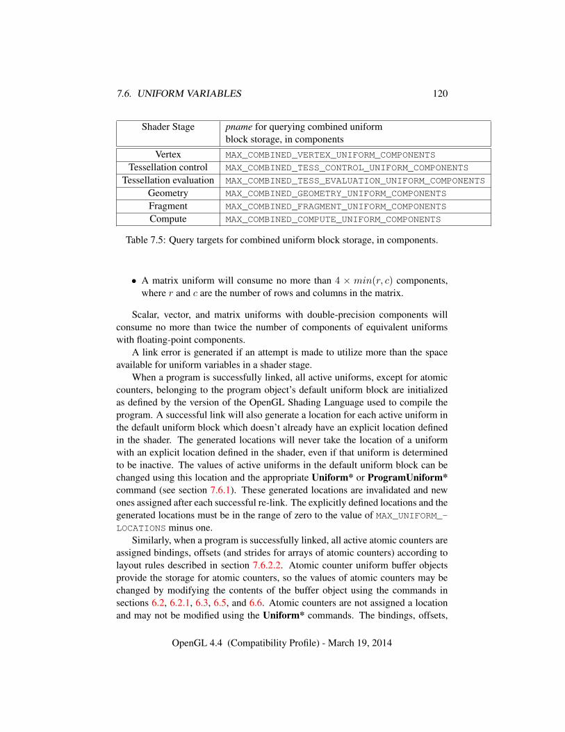
7.6. UNIFORM VARIABLES 120
Shader Stage pname for querying combined uniformblock storage, in components
Vertex MAX_COMBINED_VERTEX_UNIFORM_COMPONENTS
Tessellation control MAX_COMBINED_TESS_CONTROL_UNIFORM_COMPONENTS
Tessellation evaluation MAX_COMBINED_TESS_EVALUATION_UNIFORM_COMPONENTS
Geometry MAX_COMBINED_GEOMETRY_UNIFORM_COMPONENTS
Fragment MAX_COMBINED_FRAGMENT_UNIFORM_COMPONENTS
Compute MAX_COMBINED_COMPUTE_UNIFORM_COMPONENTS
Table 7.5: Query targets for combined uniform block storage, in components.
• A matrix uniform will consume no more than 4 × min(r, c) components,where r and c are the number of rows and columns in the matrix.
Scalar, vector, and matrix uniforms with double-precision components willconsume no more than twice the number of components of equivalent uniformswith floating-point components.
A link error is generated if an attempt is made to utilize more than the spaceavailable for uniform variables in a shader stage.
When a program is successfully linked, all active uniforms, except for atomiccounters, belonging to the program object’s default uniform block are initializedas defined by the version of the OpenGL Shading Language used to compile theprogram. A successful link will also generate a location for each active uniform inthe default uniform block which doesn’t already have an explicit location definedin the shader. The generated locations will never take the location of a uniformwith an explicit location defined in the shader, even if that uniform is determinedto be inactive. The values of active uniforms in the default uniform block can bechanged using this location and the appropriate Uniform* or ProgramUniform*command (see section 7.6.1). These generated locations are invalidated and newones assigned after each successful re-link. The explicitly defined locations and thegenerated locations must be in the range of zero to the value of MAX_UNIFORM_-LOCATIONS minus one.
Similarly, when a program is successfully linked, all active atomic counters areassigned bindings, offsets (and strides for arrays of atomic counters) according tolayout rules described in section 7.6.2.2. Atomic counter uniform buffer objectsprovide the storage for atomic counters, so the values of atomic counters may bechanged by modifying the contents of the buffer object using the commands insections 6.2, 6.2.1, 6.3, 6.5, and 6.6. Atomic counters are not assigned a locationand may not be modified using the Uniform* commands. The bindings, offsets,
OpenGL 4.4 (Compatibility Profile) - March 19, 2014
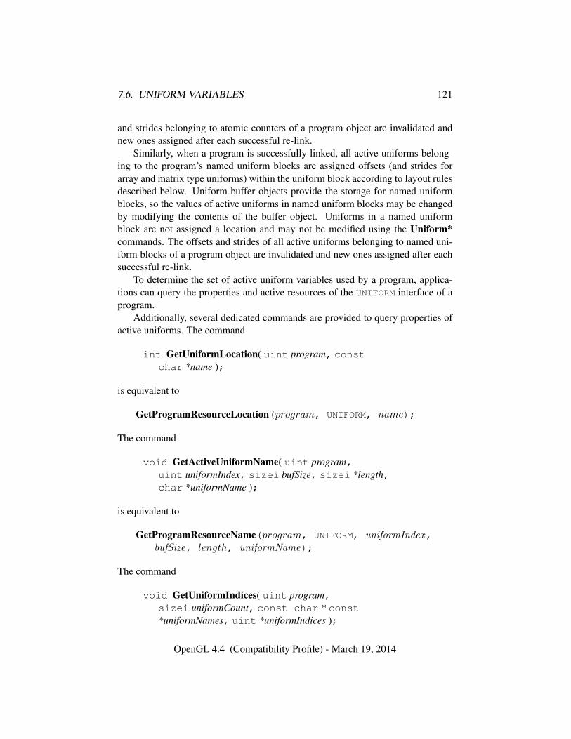
7.6. UNIFORM VARIABLES 121
and strides belonging to atomic counters of a program object are invalidated andnew ones assigned after each successful re-link.
Similarly, when a program is successfully linked, all active uniforms belong-ing to the program’s named uniform blocks are assigned offsets (and strides forarray and matrix type uniforms) within the uniform block according to layout rulesdescribed below. Uniform buffer objects provide the storage for named uniformblocks, so the values of active uniforms in named uniform blocks may be changedby modifying the contents of the buffer object. Uniforms in a named uniformblock are not assigned a location and may not be modified using the Uniform*commands. The offsets and strides of all active uniforms belonging to named uni-form blocks of a program object are invalidated and new ones assigned after eachsuccessful re-link.
To determine the set of active uniform variables used by a program, applica-tions can query the properties and active resources of the UNIFORM interface of aprogram.
Additionally, several dedicated commands are provided to query properties ofactive uniforms. The command
int GetUniformLocation( uint program, constchar *name );
is equivalent to
GetProgramResourceLocation(program, UNIFORM, name);
The command
void GetActiveUniformName( uint program,uint uniformIndex, sizei bufSize, sizei *length,char *uniformName );
is equivalent to
GetProgramResourceName(program, UNIFORM, uniformIndex,bufSize, length, uniformName);
The command
void GetUniformIndices( uint program,sizei uniformCount, const char * const*uniformNames, uint *uniformIndices );
OpenGL 4.4 (Compatibility Profile) - March 19, 2014
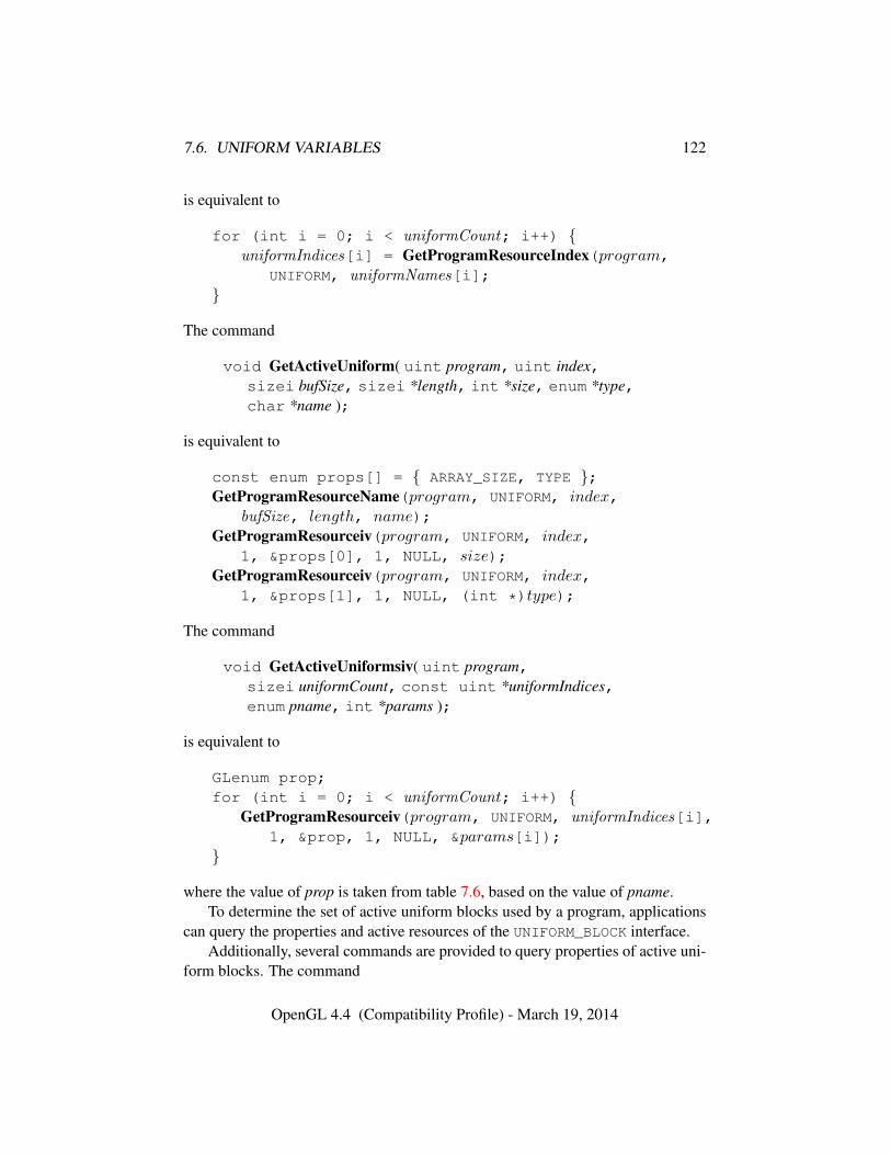
7.6. UNIFORM VARIABLES 122
is equivalent to
for (int i = 0; i < uniformCount; i++) {uniformIndices[i] = GetProgramResourceIndex(program,
UNIFORM, uniformNames[i];}
The command
void GetActiveUniform( uint program, uint index,sizei bufSize, sizei *length, int *size, enum *type,char *name );
is equivalent to
const enum props[] = { ARRAY_SIZE, TYPE };GetProgramResourceName(program, UNIFORM, index,
bufSize, length, name);GetProgramResourceiv(program, UNIFORM, index,
1, &props[0], 1, NULL, size);GetProgramResourceiv(program, UNIFORM, index,
1, &props[1], 1, NULL, (int *)type);
The command
void GetActiveUniformsiv( uint program,sizei uniformCount, const uint *uniformIndices,enum pname, int *params );
is equivalent to
GLenum prop;for (int i = 0; i < uniformCount; i++) {
GetProgramResourceiv(program, UNIFORM, uniformIndices[i],1, &prop, 1, NULL, ¶ms[i]);
}
where the value of prop is taken from table 7.6, based on the value of pname.To determine the set of active uniform blocks used by a program, applications
can query the properties and active resources of the UNIFORM_BLOCK interface.Additionally, several commands are provided to query properties of active uni-
form blocks. The command
OpenGL 4.4 (Compatibility Profile) - March 19, 2014
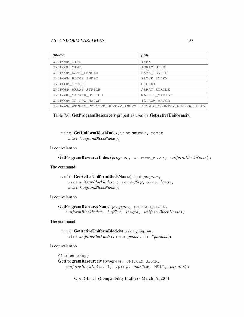
7.6. UNIFORM VARIABLES 123
pname prop
UNIFORM_TYPE TYPE
UNIFORM_SIZE ARRAY_SIZE
UNIFORM_NAME_LENGTH NAME_LENGTH
UNIFORM_BLOCK_INDEX BLOCK_INDEX
UNIFORM_OFFSET OFFSET
UNIFORM_ARRAY_STRIDE ARRAY_STRIDE
UNIFORM_MATRIX_STRIDE MATRIX_STRIDE
UNIFORM_IS_ROW_MAJOR IS_ROW_MAJOR
UNIFORM_ATOMIC_COUNTER_BUFFER_INDEX ATOMIC_COUNTER_BUFFER_INDEX
Table 7.6: GetProgramResourceiv properties used by GetActiveUniformsiv.
uint GetUniformBlockIndex( uint program, constchar *uniformBlockName );
is equivalent to
GetProgramResourceIndex(program, UNIFORM_BLOCK, uniformBlockName);
The command
void GetActiveUniformBlockName( uint program,uint uniformBlockIndex, sizei bufSize, sizei length,char *uniformBlockName );
is equivalent to
GetProgramResourceName(program, UNIFORM_BLOCK,uniformBlockIndex, bufSize, length, uniformBlockName);
The command
void GetActiveUniformBlockiv( uint program,uint uniformBlockIndex, enum pname, int *params );
is equivalent to
GLenum prop;GetProgramResourceiv(program, UNIFORM_BLOCK,
uniformBlockIndex, 1, &prop, maxSize, NULL, params);
OpenGL 4.4 (Compatibility Profile) - March 19, 2014
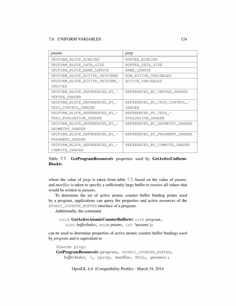
7.6. UNIFORM VARIABLES 124
pname prop
UNIFORM_BLOCK_BINDING BUFFER_BINDING
UNIFORM_BLOCK_DATA_SIZE BUFFER_DATA_SIZE
UNIFORM_BLOCK_NAME_LENGTH NAME_LENGTH
UNIFORM_BLOCK_ACTIVE_UNIFORMS NUM_ACTIVE_VARIABLES
UNIFORM_BLOCK_ACTIVE_UNIFORM_-
INDICES
ACTIVE_VARIABLES
UNIFORM_BLOCK_REFERENCED_BY_-
VERTEX_SHADER
REFERENCED_BY_VERTEX_SHADER
UNIFORM_BLOCK_REFERENCED_BY_-
TESS_CONTROL_SHADER
REFERENCED_BY_TESS_CONTROL_-
SHADER
UNIFORM_BLOCK_REFERENCED_BY_-
TESS_EVALUATION_SHADER
REFERENCED_BY_TESS_-
EVALUATION_SHADER
UNIFORM_BLOCK_REFERENCED_BY_-
GEOMETRY_SHADER
REFERENCED_BY_GEOMETRY_SHADER
UNIFORM_BLOCK_REFERENCED_BY_-
FRAGMENT_SHADER
REFERENCED_BY_FRAGMENT_SHADER
UNIFORM_BLOCK_REFERENCED_BY_-
COMPUTE_SHADER
REFERENCED_BY_COMPUTE_SHADER
Table 7.7: GetProgramResourceiv properties used by GetActiveUniform-Blockiv.
where the value of prop is taken from table 7.7, based on the value of pname,and maxSize is taken to specify a sufficiently large buffer to receive all values thatwould be written to params.
To determine the set of active atomic counter buffer binding points usedby a program, applications can query the properties and active resources of theATOMIC_COUNTER_BUFFER interface of a program.
Additionally, the command
void GetActiveAtomicCounterBufferiv( uint program,uint bufferIndex, enum pname, int *params );
can be used to determine properties of active atomic counter buffer bindings usedby program and is equivalent to
GLenum prop;GetProgramResourceiv(program, ATOMIC_COUNTER_BUFFER,
bufferIndex, 1, &prop, maxSize, NULL, params);
OpenGL 4.4 (Compatibility Profile) - March 19, 2014
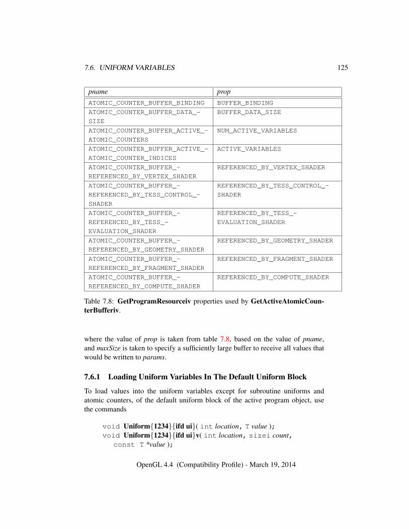
7.6. UNIFORM VARIABLES 125
pname prop
ATOMIC_COUNTER_BUFFER_BINDING BUFFER_BINDING
ATOMIC_COUNTER_BUFFER_DATA_-
SIZE
BUFFER_DATA_SIZE
ATOMIC_COUNTER_BUFFER_ACTIVE_-
ATOMIC_COUNTERS
NUM_ACTIVE_VARIABLES
ATOMIC_COUNTER_BUFFER_ACTIVE_-
ATOMIC_COUNTER_INDICES
ACTIVE_VARIABLES
ATOMIC_COUNTER_BUFFER_-
REFERENCED_BY_VERTEX_SHADER
REFERENCED_BY_VERTEX_SHADER
ATOMIC_COUNTER_BUFFER_-
REFERENCED_BY_TESS_CONTROL_-
SHADER
REFERENCED_BY_TESS_CONTROL_-
SHADER
ATOMIC_COUNTER_BUFFER_-
REFERENCED_BY_TESS_-
EVALUATION_SHADER
REFERENCED_BY_TESS_-
EVALUATION_SHADER
ATOMIC_COUNTER_BUFFER_-
REFERENCED_BY_GEOMETRY_SHADER
REFERENCED_BY_GEOMETRY_SHADER
ATOMIC_COUNTER_BUFFER_-
REFERENCED_BY_FRAGMENT_SHADER
REFERENCED_BY_FRAGMENT_SHADER
ATOMIC_COUNTER_BUFFER_-
REFERENCED_BY_COMPUTE_SHADER
REFERENCED_BY_COMPUTE_SHADER
Table 7.8: GetProgramResourceiv properties used by GetActiveAtomicCoun-terBufferiv.
where the value of prop is taken from table 7.8, based on the value of pname,and maxSize is taken to specify a sufficiently large buffer to receive all values thatwould be written to params.
7.6.1 Loading Uniform Variables In The Default Uniform Block
To load values into the uniform variables except for subroutine uniforms andatomic counters, of the default uniform block of the active program object, usethe commands
void Uniform{1234}{ifd ui}( int location, T value );void Uniform{1234}{ifd ui}v( int location, sizei count,
const T *value );
OpenGL 4.4 (Compatibility Profile) - March 19, 2014
7.6. UNIFORM VARIABLES 126
void UniformMatrix{234}{fd}v( int location, sizei count,boolean transpose, const float *value );
void UniformMatrix{2x3,3x2,2x4,4x2,3x4,4x3}{fd}v(int location, sizei count, boolean transpose, constfloat *value );
If a non-zero program object is bound by UseProgram, it is the active pro-gram object whose uniforms are updated by these commands. If no program ob-ject is bound using UseProgram, the active program object of the current programpipeline object set by ActiveShaderProgram is the active program object. If thecurrent program pipeline object has no active program or there is no current pro-gram pipeline object, then there is no active program.
The given values are loaded into the default uniform block uniform variablelocation identified by location and associated with a uniform variable.
The Uniform*f{v} commands will load count sets of one to four floating-pointvalues into a uniform defined as a float, a floating-point vector, or an array of eitherof these types.
The Uniform*d{v} commands will load count sets of one to four double-precision floating-point values into a uniform defined as a double, a double vector,or an array of either of these types.
The Uniform*i{v} commands will load count sets of one to four integer valuesinto a uniform defined as a sampler, an image, an integer, an integer vector, or anarray of any of these types. Only the Uniform1i{v} commands can be used to loadsampler and image values (see sections 7.10 and 7.11).
The Uniform*ui{v} commands will load count sets of one to four unsignedinteger values into a uniform defined as a unsigned integer, an unsigned integervector, or an array of either of these types.
The UniformMatrix{234}fv and UniformMatrix{234}dv commands willload count 2 × 2, 3 × 3, or 4 × 4 matrices (corresponding to 2, 3, or 4 in thecommand name) of single- or double-precision floating-point values, respectively,into a uniform defined as a matrix or an array of matrices. If transpose is FALSE,the matrix is specified in column major order, otherwise in row major order.
The UniformMatrix{2x3,3x2,2x4,4x2,3x4,4x3}fv and UniformMa-trix{2x3,3x2,2x4,4x2,3x4,4x3}dv commands will load count 2× 3, 3× 2, 2× 4,4 × 2, 3 × 4, or 4 × 3 matrices (corresponding to the numbers in the commandname) of single- or double-precision floating-point values, respectively, into auniform defined as a matrix or an array of matrices. The first number in thecommand name is the number of columns; the second is the number of rows.For example, UniformMatrix2x4fv is used to load a single-precision matrixconsisting of two columns and four rows. If transpose is FALSE, the matrix is
OpenGL 4.4 (Compatibility Profile) - March 19, 2014
7.6. UNIFORM VARIABLES 127
specified in column major order, otherwise in row major order.When loading values for a uniform declared as a boolean, a boolean vector,
or an array of either of these types, any of the Uniform*i{v}, Uniform*ui{v},and Uniform*f{v} commands can be used. Type conversion is done by the GL.Boolean values are set to FALSE if the corresponding input value is 0 or 0.0f, andset to TRUE otherwise. The Uniform* command used must match the size of theuniform, as declared in the shader. For example, to load a uniform declared as abvec2, any of the Uniform2{if ui}* commands may be used.
For all other uniform types loadable with Uniform* commands, the commandused must match the size and type of the uniform, as declared in the shader, andno type conversions are done. For example, to load a uniform declared as a vec4,Uniform4f{v} must be used, and to load a uniform declared as a dmat3, Unifor-mMatrix3dv must be used.
When loading N elements starting at an arbitrary position k in a uniform de-clared as an array, elements k through k + N − 1 in the array will be replacedwith the new values. Values for any array element that exceeds the highest arrayelement index used, as reported by GetActiveUniform, will be ignored by the GL.
If the value of location is -1, the Uniform* commands will silently ignore thedata passed in, and the current uniform values will not be changed.
Errors
An INVALID_VALUE error is generated if count is negative.An INVALID_VALUE error is generated if Uniform1i{v} is used to set a
sampler uniform to a value less than zero or greater than or equal to the valueof MAX_COMBINED_TEXTURE_IMAGE_UNITS.
An INVALID_VALUE error is generated if Uniform1i{v} is used to set animage uniform to a value less than zero or greater than or equal to the value ofMAX_IMAGE_UNITS.
An INVALID_OPERATION error is generated if any of the following con-ditions occur:• the size indicated in the name of the Uniform* command used does not
match the size of the uniform declared in the shader,
• the component type and count indicated in the name of the Uniform*command used does not match the type of the uniform declared inthe shader, where a boolean uniform component type is consideredto match any of the Uniform*i{v}, Uniform*ui{v}, or Uniform*f{v}commands.
OpenGL 4.4 (Compatibility Profile) - March 19, 2014
7.6. UNIFORM VARIABLES 128
• count is greater than one, and the uniform declared in the shader is notan array variable,
• no variable with a location of location exists in the program object cur-rently in use and location is not -1, or
• a sampler or image uniform is loaded with any of the Uniform* com-mands other than Uniform1i{v}.
• there is no active program object in use.
To load values into the uniform variables of the default uniform block of aprogram which may not necessarily be bound, use the commands
void ProgramUniform{1234}{ifd}( uint program,int location, T value );
void ProgramUniform{1234}{ifd}v( uint program,int location, sizei count, const T *value );
void ProgramUniform{1234}ui( uint program, int location,T value );
void ProgramUniform{1234}uiv( uint program,int location, sizei count, const T *value );
void ProgramUniformMatrix{234}{fd}v( uint program,int location, sizei count, boolean transpose, constT *value );
void ProgramUniformMatrix{2x3,3x2,2x4,4x2,3x4,4x3}{fd}v(uint program, int location, sizei count,boolean transpose, const T *value );
These commands operate identically to the corresponding commands abovewithout Program in the command name except, rather than updating the cur-rently active program object, these Program commands update the program ob-ject named by the initial program parameter.The remaining parameters followingthe initial program parameter match the parameters for the corresponding non-Program uniform command.
Errors
An INVALID_VALUE error is generated if program is not the name of ei-ther a program or shader object.
An INVALID_OPERATION error is generated if program is the name of ashader object.
OpenGL 4.4 (Compatibility Profile) - March 19, 2014
7.6. UNIFORM VARIABLES 129
An INVALID_OPERATION error is generated if program has not beenlinked, or was last linked unsuccessfully.
In addition, all errors described for the corresponding Uniform* com-mands apply.
7.6.2 Uniform Blocks
The values of uniforms arranged in named uniform blocks are extracted from bufferobject storage. The mechanisms for placing individual uniforms in a buffer objectand connecting a uniform block to an individual buffer object are described below.
There is a set of implementation-dependent maximums for the number of activeuniform blocks used by each shader stage. If the number of uniform blocks usedby any shader stage in the program exceeds its corresponding limit, the programwill fail to link. The limits for vertex, tessellation control, tessellation evaluation,geometry, fragment, and compute shaders can be obtained by calling GetIntegervwith pname values of MAX_VERTEX_UNIFORM_BLOCKS, MAX_TESS_CONTROL_-UNIFORM_BLOCKS, MAX_TESS_EVALUATION_UNIFORM_BLOCKS, MAX_-
GEOMETRY_UNIFORM_BLOCKS, MAX_FRAGMENT_UNIFORM_BLOCKS, and MAX_-
COMPUTE_UNIFORM_BLOCKS, respectively.Additionally, there is an implementation-dependent limit on the sum of the
number of active uniform blocks used by each shader stage of a program. If auniform block is used by multiple shader stages, each such use counts separatelyagainst this combined limit. The combined uniform block use limit can be obtainedby calling GetIntegerv with a pname of MAX_COMBINED_UNIFORM_BLOCKS.
When a named uniform block is declared by multiple shaders in a program, itmust be declared identically in each shader. The uniforms within the block mustbe declared with the same names, types and layout qualifiers, and in the sameorder. If a program contains multiple shaders with different declarations for thesame named uniform block, the program will fail to link.
7.6.2.1 Uniform Buffer Object Storage
When stored in buffer objects associated with uniform blocks, uniforms are repre-sented in memory as follows:
• Members of type bool, int, uint, float, and double are respectivelyextracted from a buffer object by reading a single uint, int, uint, float,or double value at the specified offset.
• Vectors with N elements with basic data types of bool, int, uint, float,or double are extracted as N values in consecutive memory locations be-
OpenGL 4.4 (Compatibility Profile) - March 19, 2014
7.6. UNIFORM VARIABLES 130
ginning at the specified offset, with components stored in order with the first(X) component at the lowest offset. The GL data type used for componentextraction is derived according to the rules for scalar members above.
• Column-major matrices with C columns and R rows (using the typesdmatCxR and matCxR for double-precision and floating-point componentsrespectively, or simply dmatC and matC respectively if C = R) are treatedas an array of C column vectors, each consisting of R double-precision orfloating-point components. The column vectors will be stored in order, withcolumn zero at the lowest offset. The difference in offsets between consecu-tive columns of the matrix will be referred to as the column stride, and is con-stant across the matrix. The column stride is an implementation-dependentfunction of the matrix type, and may be determined after a program is linkedby querying the MATRIX_STRIDE interface using GetProgramResourceiv(see section 7.3.1).
• Row-major matrices with C columns andR rows (using the types dmatCxRand matCxR for double-precision and floating-point components respec-tively, or simply dmatC and matC respectively if C = R) are treated asan array ofR row vectors, each consisting of C double-precision or floating-point components. The row vectors will be stored in order, with row zero atthe lowest offset. The difference in offsets between consecutive rows of thematrix will be referred to as the row stride, and is constant across the matrix.The row stride is an implementation-dependent function of the matrix type,and may be determined after a program is linked by querying the MATRIX_-STRIDE interface using GetProgramResourceiv (see section 7.3.1).
• Arrays of scalars, vectors, and matrices are stored in memory by elementorder, with array member zero at the lowest offset. The difference in offsetsbetween each pair of elements in the array in basic machine units is referredto as the array stride, and is constant across the entire array. The array stride,UNIFORM_ARRAY_STRIDE, is an implementation-dependent value and maybe queried after a program is linked.
7.6.2.2 Standard Uniform Block Layout
By default, uniforms contained within a uniform block are extracted from bufferstorage in an implementation-dependent manner. Applications may query the off-sets assigned to uniforms inside uniform blocks with query functions provided bythe GL.
OpenGL 4.4 (Compatibility Profile) - March 19, 2014
7.6. UNIFORM VARIABLES 131
The layout qualifier provides shaders with control of the layout of uniformswithin a uniform block. When the std140 layout is specified, the offset of eachuniform in a uniform block can be derived from the definition of the uniform blockby applying the set of rules described below.
When using the std140 storage layout, structures will be laid out in bufferstorage with its members stored in monotonically increasing order based on theirlocation in the declaration. A structure and each structure member have a baseoffset and a base alignment, from which an aligned offset is computed by roundingthe base offset up to a multiple of the base alignment. The base offset of the firstmember of a structure is taken from the aligned offset of the structure itself. Thebase offset of all other structure members is derived by taking the offset of thelast basic machine unit consumed by the previous member and adding one. Eachstructure member is stored in memory at its aligned offset. The members of a top-level uniform block are laid out in buffer storage by treating the uniform block asa structure with a base offset of zero.
1. If the member is a scalar consuming N basic machine units, the base align-ment is N .
2. If the member is a two- or four-component vector with components consum-ing N basic machine units, the base alignment is 2N or 4N , respectively.
3. If the member is a three-component vector with components consuming Nbasic machine units, the base alignment is 4N .
4. If the member is an array of scalars or vectors, the base alignment and arraystride are set to match the base alignment of a single array element, accordingto rules (1), (2), and (3), and rounded up to the base alignment of a vec4. Thearray may have padding at the end; the base offset of the member followingthe array is rounded up to the next multiple of the base alignment.
5. If the member is a column-major matrix with C columns and R rows, thematrix is stored identically to an array of C column vectors with R compo-nents each, according to rule (4).
6. If the member is an array of S column-major matrices with C columns andR rows, the matrix is stored identically to a row of S × C column vectorswith R components each, according to rule (4).
7. If the member is a row-major matrix with C columns andR rows, the matrixis stored identically to an array of R row vectors with C components each,according to rule (4).
OpenGL 4.4 (Compatibility Profile) - March 19, 2014

7.6. UNIFORM VARIABLES 132
8. If the member is an array of S row-major matrices with C columns and Rrows, the matrix is stored identically to a row of S × R row vectors with Ccomponents each, according to rule (4).
9. If the member is a structure, the base alignment of the structure is N , whereN is the largest base alignment value of any of its members, and roundedup to the base alignment of a vec4. The individual members of this sub-structure are then assigned offsets by applying this set of rules recursively,where the base offset of the first member of the sub-structure is equal to thealigned offset of the structure. The structure may have padding at the end;the base offset of the member following the sub-structure is rounded up tothe next multiple of the base alignment of the structure.
10. If the member is an array of S structures, the S elements of the array are laidout in order, according to rule (9).
Shader storage blocks (see section 7.8) also support the std140 layout qual-ifier, as well as a std430 qualifier not supported for uniform blocks. When usingthe std430 storage layout, shader storage blocks will be laid out in buffer storageidentically to uniform and shader storage blocks using the std140 layout, exceptthat the base alignment and stride of arrays of scalars and vectors in rule 4 and ofstructures in rule 9 are not rounded up a multiple of the base alignment of a vec4.
7.6.3 Uniform Buffer Object Bindings
The value an active uniform inside a named uniform block is extracted from thedata store of a buffer object bound to one of an array of uniform buffer bindingpoints. The number of binding points can be queried using GetIntegerv with theconstant MAX_UNIFORM_BUFFER_BINDINGS.
Regions of buffer objects are bound as storage for uniform blocks by callingBindBuffer* commands (see section 6) with target set to UNIFORM_BUFFER.
Each of a program’s active uniform blocks has a corresponding uniform bufferobject binding point. The binding is established when a program is linked or re-linked, and the initial value of the binding is specified by a layout qualifier (ifpresent), or zero otherwise. The binding point can be assigned by calling:
void UniformBlockBinding( uint program,uint uniformBlockIndex, uint uniformBlockBinding );
program is a name of a program object for which the command LinkProgram hasbeen issued in the past.
OpenGL 4.4 (Compatibility Profile) - March 19, 2014
7.7. ATOMIC COUNTER BUFFERS 133
If successful, UniformBlockBinding specifies that program will use the datastore of the buffer object bound to the binding point uniformBlockBinding to extractthe values of the uniforms in the uniform block identified by uniformBlockIndex.
When executing shaders that access uniform blocks, the binding point corre-sponding to each active uniform block must be populated with a buffer object witha size no smaller than the minimum required size of the uniform block (the valueof UNIFORM_BLOCK_DATA_SIZE). For binding points populated by BindBuffer-Range, the size in question is the value of the size parameter. If any active uniformblock is not backed by a sufficiently large buffer object, the results of shader ex-ecution may be undefined or modified, as described in section 6.4. Shaders maybe executed to process the primitives and vertices specified by any command thattransfers vertices to the GL. Shaders may also be executed as a result of DrawPix-els, Bitmap, or RasterPos* commands.
Errors
An INVALID_VALUE error is generated if program is not the name of ei-ther a program or shader object.
An INVALID_OPERATION error is generated if program is the name of ashader object.
An INVALID_VALUE error is generated if uniformBlockIndex is not anactive uniform block index of program, or if uniformBlockBinding is greaterthan or equal to the value of MAX_UNIFORM_BUFFER_BINDINGS.
7.7 Atomic Counter Buffers
The values of atomic counters are backed by buffer object storage. The mecha-nisms for accessing individual atomic counters in a buffer object and connecting toan atomic counter are described in this section.
There is a set of implementation-dependent maximums for the number of activeatomic counter buffers referenced by each shader. If the number of atomic counterbuffer bindings referenced by any shader in the program exceeds the correspondinglimit, the program will fail to link. The limits for vertex, tessellation control, tes-sellation evaluation, geometry, fragment, and compute shaders can be obtained bycalling GetIntegerv with pname values of MAX_VERTEX_ATOMIC_COUNTER_-BUFFERS, MAX_TESS_CONTROL_ATOMIC_COUNTER_BUFFERS, MAX_-
TESS_EVALUATION_ATOMIC_COUNTER_BUFFERS, MAX_GEOMETRY_ATOMIC_-COUNTER_BUFFERS, MAX_FRAGMENT_ATOMIC_COUNTER_BUFFERS, and MAX_-
COMPUTE_ATOMIC_COUNTER_BUFFERS, respectively.
OpenGL 4.4 (Compatibility Profile) - March 19, 2014
7.7. ATOMIC COUNTER BUFFERS 134
Additionally, there is an implementation-dependent limit on the sum of thenumber of active atomic counter buffers used by each shader stage of a program.If an atomic counter buffer is used by multiple shader stages, each such use countsseparately against this combined limit. The combined atomic counter buffer uselimit can be obtained by calling GetIntegerv with a pname of MAX_COMBINED_-ATOMIC_COUNTER_BUFFERS.
7.7.1 Atomic Counter Buffer Object Storage
Atomic counters stored in buffer objects are represented in memory as follows:
• Members of type atomic_uint are extracted from a buffer object by read-ing a single uint-typed value at the specified offset.
• Arrays of type atomic_uint are stored in memory by element order, witharray element member zero at the lowest offset. The difference in offsetsbetween each pair of elements in the array in basic machine units is referredto as the array stride, and is constant across the entire array. The array stride,UNIFORM_ARRAY_STRIDE, is an implementation-dependent value and maybe queried after a program is linked.
7.7.2 Atomic Counter Buffer Bindings
The value of an active atomic counter is extracted from or written to the data storeof a buffer object bound to one of an array of atomic counter buffer binding points.The number of binding points can be queried by calling GetIntegerv with a pnameof MAX_ATOMIC_COUNTER_BUFFER_BINDINGS.
Regions of buffer objects are bound as storage for atomic counters by callingone of the BindBuffer* commands (see section 6) with target set to ATOMIC_-
COUNTER_BUFFER.Each of a program’s active atomic counter buffer bindings has a corresponding
atomic counter buffer binding point. This binding point is established with thelayout qualifier in the shader text, either explicitly or implicitly, as described inthe OpenGL Shading Language Specification.
When executing shaders that access atomic counters, each active atomiccounter buffer must be populated with a buffer object with a size no smaller than theminimum required size for that buffer (the value of BUFFER_DATA_SIZE returnedby GetProgramResourceiv). For binding points populated by BindBufferRange,the size in question is the value of the size parameter. If any active atomic counterbuffer is not backed by a sufficiently large buffer object, the results of shader exe-cution may be undefined or modified, as described in section 6.4.
OpenGL 4.4 (Compatibility Profile) - March 19, 2014
7.8. SHADER BUFFER VARIABLES AND SHADER STORAGE BLOCKS135
7.8 Shader Buffer Variables and Shader Storage Blocks
Shaders can declare named buffer variables, as described in the OpenGL ShadingLanguage Specification. Sets of buffer variables are grouped into interface blockscalled shader storage blocks. The values of each buffer variable in a shader storageblock are read from or written to the data store of a buffer object bound to thebinding point associated with the block. The values of active buffer variables maybe changed by executing shaders that assign values to them or perform atomicmemory operations on them; by modifying the contents of the bound buffer object’sdata store with the commands in sections 6.2, 6.2.1, 6.3, 6.5, and 6.6; by bindinga new buffer object to the binding point associated with the block; or by changingthe binding point associated with the block.
Buffer variables in shader storage blocks are represented in memory in thesame way as uniforms stored in uniform blocks, as described in section 7.6.2.1.When a program is linked successfully, each active buffer variable is assigned anoffset relative to the base of the buffer object binding associated with its shaderstorage block. For buffer variables declared as arrays and matrices, strides betweenarray elements or matrix columns or rows will also be assigned. Offsets and stridesof buffer variables will be assigned in an implementation-dependent manner unlessthe shader storage block is declared using the std140 or std430 storage layoutqualifiers. For std140 and std430 shader storage blocks, offsets will be assignedusing the method described in section 7.6.2.2. If a program is re-linked, existingbuffer variable offsets and strides are invalidated, and a new set of active variables,offsets, and strides will be generated.
The total amount of buffer object storage that can be accessed in any shaderstorage block is subject to an implementation-dependent limit. The maximumamount of available space, in basic machine units, can be queried by calling Get-Integerv with pname MAX_SHADER_STORAGE_BLOCK_SIZE. If the amount ofstorage required for any shader storage block exceeds this limit, a program willfail to link.
If the number of active shader storage blocks referenced by theshaders in a program exceeds implementation-dependent limits, the pro-gram will fail to link. The limits for vertex, tessellation control, tes-sellation evaluation, geometry, fragment, and compute shaders can be ob-tained by calling GetIntegerv with pname values of MAX_VERTEX_SHADER_-
STORAGE_BLOCKS, MAX_TESS_CONTROL_SHADER_STORAGE_BLOCKS, MAX_-
TESS_EVALUATION_SHADER_STORAGE_BLOCKS, MAX_GEOMETRY_SHADER_-
STORAGE_BLOCKS, MAX_FRAGMENT_SHADER_STORAGE_BLOCKS, and MAX_-
COMPUTE_SHADER_STORAGE_BLOCKS, respectively. Additionally, a program willfail to link if the sum of the number of active shader storage blocks referenced by
OpenGL 4.4 (Compatibility Profile) - March 19, 2014

7.8. SHADER BUFFER VARIABLES AND SHADER STORAGE BLOCKS136
each shader stage in a program exceeds the value of the implementation-dependentlimit MAX_COMBINED_SHADER_STORAGE_BLOCKS. If a shader storage block in aprogram is referenced by multiple shaders, each such reference counts separatelyagainst this combined limit.
When a named shader storage block is declared by multiple shaders in a pro-gram, it must be declared identically in each shader. The buffer variables withinthe block must be declared with the same names, types, qualification, and decla-ration order. If a program contains multiple shaders with different declarations forthe same named shader storage block, the program will fail to link.
Regions of buffer objects are bound as storage for shader storage blocks bycalling one of the BindBuffer* commands (see section 6) with target SHADER_-STORAGE_BUFFER.
Each of a program’s active shader storage blocks has a corresponding shaderstorage buffer object binding point. When a program object is linked, the shaderstorage buffer object binding point assigned to each of its active shader storageblocks is reset to the value specified by the corresponding binding layout qual-ifier, if present, or zero otherwise. After a program is linked, the command
void ShaderStorageBlockBinding( uint program,uint storageBlockIndex, uint storageBlockBinding );
changes the active shader storage block with an assigned index of storage-BlockIndex in program object program. ShaderStorageBlockBinding specifiesthat program will use the data store of the buffer object bound to the binding pointstorageBlockBinding to read and write the values of the buffer variables in theshader storage block identified by storageBlockIndex.
Errors
An INVALID_VALUE error is generated if program is not the name of ei-ther a program or shader object.
An INVALID_OPERATION error is generated if program is the name of ashader object.
An INVALID_VALUE error is generated if storageBlockIndex is not anactive shader storage block index in program, or if storageBlockBinding isgreater than or equal to the value of MAX_SHADER_STORAGE_BUFFER_-
BINDINGS.
When executing shaders that access shader storage blocks, the binding pointcorresponding to each active shader storage block must be populated with a buffer
OpenGL 4.4 (Compatibility Profile) - March 19, 2014
7.9. SUBROUTINE UNIFORM VARIABLES 137
object with a size no smaller than the minimum required size of the shader stor-age block (the value of BUFFER_SIZE for the appropriate SHADER_STORAGE_-
BUFFER resource). For binding points populated by BindBufferRange, the size inquestion is the value of the size parameter or the size of the buffer minus the valueof the offset parameter, whichever is smaller. If any active shader storage block isnot backed by a sufficiently large buffer object, the results of shader execution maybe undefined or modified, as described in section 6.4.
7.9 Subroutine Uniform Variables
Subroutine uniform variables are similar to uniform variables, except they are con-text state rather than program state, and apply only to a single program stage. Hav-ing subroutine uniforms be context state allows them to have different values if theprogram is used in multiple contexts simultaneously. There is a set of subroutineuniforms for each shader stage.
A subroutine uniform may have an explicit location specified in the shader.At link time, all active subroutine uniforms without an explicit location will beassigned a unique location. The value of ACTIVE_SUBROUTINE_UNIFORM_-
LOCATIONS for a program object is the largest assigned or generated location plusone. An assigned location will never take the location of an explicitly assignedlocation, even if that subroutine uniform is inactive. Between the location zero andthe value of ACTIVE_SUBROUTINE_UNIFORM_LOCATIONS minus one there maybe unused locations, either because they were not assigned a subroutine uniform orbecause the subroutine uniform was determined to be inactive by the linker. Theselocations will be ignored when assigning the subroutine index as described below.
There is an implementation-dependent limit on the number of active subrou-tine uniform locations in each shader stage; a program will fail to link if the num-ber of subroutine uniform locations required is greater than the value of MAX_-SUBROUTINE_UNIFORM_LOCATIONS or if an explicit subroutine uniform locationis outside this limit. For active subroutine uniforms declared as arrays, the declaredarray elements are assigned consecutive locations.
Each function in a shader associated with a subroutine type is considered anactive subroutine, unless the compiler conclusively determines that the functioncould never be assigned to an active subroutine uniform. The subroutine func-tions can be assigned an explicit index in the shader between zero and the valueof MAX_SUBROUTINES minus one. At link time, all active subroutines without anexplicit index will be assigned an index between zero and the value of ACTIVE_-SUBROUTINES minus one. An assigned index will never take the same index ofan explicitly assigned index in the shader, even if that subroutine is inactive. Be-
OpenGL 4.4 (Compatibility Profile) - March 19, 2014
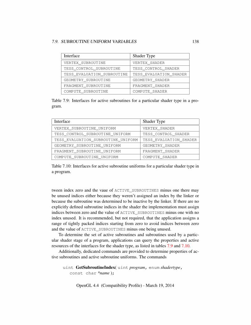
7.9. SUBROUTINE UNIFORM VARIABLES 138
Interface Shader TypeVERTEX_SUBROUTINE VERTEX_SHADER
TESS_CONTROL_SUBROUTINE TESS_CONTROL_SHADER
TESS_EVALUATION_SUBROUTINE TESS_EVALUATION_SHADER
GEOMETRY_SUBROUTINE GEOMETRY_SHADER
FRAGMENT_SUBROUTINE FRAGMENT_SHADER
COMPUTE_SUBROUTINE COMPUTE_SHADER
Table 7.9: Interfaces for active subroutines for a particular shader type in a pro-gram.
Interface Shader TypeVERTEX_SUBROUTINE_UNIFORM VERTEX_SHADER
TESS_CONTROL_SUBROUTINE_UNIFORM TESS_CONTROL_SHADER
TESS_EVALUATION_SUBROUTINE_UNIFORM TESS_EVALUATION_SHADER
GEOMETRY_SUBROUTINE_UNIFORM GEOMETRY_SHADER
FRAGMENT_SUBROUTINE_UNIFORM FRAGMENT_SHADER
COMPUTE_SUBROUTINE_UNIFORM COMPUTE_SHADER
Table 7.10: Interfaces for active subroutine uniforms for a particular shader type ina program.
tween index zero and the vaue of ACTIVE_SUBROUTINES minus one there maybe unused indices either because they weren’t assigned an index by the linker orbecause the subroutine was determined to be inactive by the linker. If there are noexplicitly defined subroutine indices in the shader the implementation must assignindices between zero and the value of ACTIVE_SUBROUTINES minus one with noindex unused. It is recommended, but not required, that the application assigns arange of tightly packed indices starting from zero to avoid indices between zeroand the value of ACTIVE_SUBROUTINES minus one being unused.
To determine the set of active subroutines and subroutines used by a partic-ular shader stage of a program, applications can query the properties and activeresources of the interfaces for the shader type, as listed in tables 7.9 and 7.10.
Additionally, dedicated commands are provided to determine properties of ac-tive subroutines and active subroutine uniforms. The commands
uint GetSubroutineIndex( uint program, enum shadertype,const char *name );
OpenGL 4.4 (Compatibility Profile) - March 19, 2014
7.9. SUBROUTINE UNIFORM VARIABLES 139
void GetActiveSubroutineName( uint program,enum shadertype, uint index, sizei bufsize,sizei *length, char *name );
are equivalent to
GetProgramResourceIndex(program, programInterface, name);
and
GetProgramResourceName(program, programInterface,index, bufsize, length, name);
respectively, where programInterface is taken from table 7.9 according to the valueof shadertype.
The commands
int GetSubroutineUniformLocation( uint program,enum shadertype, const char *name );
void GetActiveSubroutineUniformName( uint program,enum shadertype, uint index, sizei bufsize,sizei *length, char *name );
void GetActiveSubroutineUniformiv( uint program,enum shadertype, uint index, enum pname, int *values );
are equivalent to
GetProgramResourceLocation(program, programInterface, name);
GetProgramResourceName(program, programInterface,index, bufsize, length, name);
and
GetProgramResourceiv(program, programInterface,index, 1, &pname, maxSize, NULL, values);
respectively, where programInterface is taken from table 7.10 according to thevalue of shadertype. For GetActiveSubroutineUniformiv, pname must be one ofNUM_COMPATIBLE_SUBROUTINES or COMPATIBLE_SUBROUTINES, and maxSizeis taken to specify a sufficiently large buffer to receive all values that would bewritten to params.
The command
OpenGL 4.4 (Compatibility Profile) - March 19, 2014
7.10. SAMPLERS 140
void UniformSubroutinesuiv( enum shadertype, sizei count,const uint *indices );
will load all active subroutine uniforms for shader stage shadertype with subrou-tine indices from indices, storing indices[i] into the uniform at location i. Theindices for any locations between zero and the value of ACTIVE_SUBROUTINE_-UNIFORM_LOCATIONS minus one which are not used will be ignored.
Errors
An INVALID_ENUM error is generated if shadertype is not one of the val-ues in table 7.1,
An INVALID_VALUE error is generated if count is negative, is not equal tothe value of ACTIVE_SUBROUTINE_UNIFORM_LOCATIONS for the programcurrently in use at shader stage shadertype, or if the uniform at location iis used and the value in indices[i] is greater than or equal to the value ofACTIVE_SUBROUTINES for the shader stage.
An INVALID_VALUE error is generated if the value of indices[i] for a useduniform location specifies an unused subroutine index.
An INVALID_OPERATION error is generated if, for any subroutine indexbeing loaded to a particular uniform location, the function corresponding to thesubroutine index was not associated (as defined in section 6.1.2 of the OpenGLShading Language Specification) with the type of the subroutine variable atthat location.
An INVALID_OPERATION error is generated if no program is active forthe shader stage identified by shadertype.
Each subroutine uniform must have at least one subroutine to assign to the uni-form. A program will fail to link if any stage has one or more subroutine uniformsthat has no subroutine associated with the subroutine type of the uniform.
When the active program for a shader stage is re-linked or changed by a callto UseProgram, BindProgramPipeline, or UseProgramStages, subroutine uni-forms for that stage are reset to arbitrarily chosen default functions with compatiblesubroutine types.
7.10 Samplers
Samplers are special uniforms used in the OpenGL Shading Language to identifythe texture object used for each texture lookup. The value of a sampler indicatesthe texture image unit being accessed. Setting a sampler’s value to i selects texture
OpenGL 4.4 (Compatibility Profile) - March 19, 2014
7.11. IMAGES 141
image unit number i. The values of i ranges from zero to the implementation-dependent maximum supported number of texture image units minus one.
The type of the sampler identifies the target on the texture image unit, as shownin table 7.3 for sampler* types. The texture object bound to that texture imageunit’s target is then used for the texture lookup. For example, a variable of typesampler2D selects target TEXTURE_2D on its texture image unit. Binding of tex-ture objects to targets is done as usual with BindTexture. Selecting the textureimage unit to bind to is done as usual with ActiveTexture.
The location of a sampler is queried with GetUniformLocation, just like anyuniform variable. Sampler values must be set by calling Uniform1i{v}.
Errors
It is not allowed to have variables of different sampler types pointing tothe same texture image unit within a program object. This situation can onlybe detected at the next rendering command issued which triggers shader invo-cations, and an INVALID_OPERATION error will then be generated.
Active samplers are samplers actually being used in a program object. TheLinkProgram command determines if a sampler is active or not. The LinkPro-gram command will attempt to determine if the active samplers in the shader(s)contained in the program object exceed the maximum allowable limits. If it de-termines that the count of active samplers exceeds the allowable limits, then thelink fails (these limits can be different for different types of shaders). Each activesampler variable counts against the limit, even if multiple samplers refer to thesame texture image unit. If this cannot be determined at link time (for example,if the program object only contains a vertex shader), then it will be determinedat the next rendering command issued which triggers shader invocations, and anINVALID_OPERATION error will then be generated.
7.11 Images
Images are special uniforms used in the OpenGL Shading Language to identify alevel of a texture to be read or written using built-in image load, store, and atomicfunctions in the manner described in section 8.26. The value of an image uniform isan integer specifying the image unit accessed. Image units are numbered beginningat zero, and there is an implementation-dependent number of available image units(the value of MAX_IMAGE_UNITS).
Note that image units used for image variables are independent of the texture
OpenGL 4.4 (Compatibility Profile) - March 19, 2014
7.12. SHADER MEMORY ACCESS 142
image units used for sampler variables; the number of units provided by the imple-mentation may differ. Textures are bound independently and separately to imageand texture image units.
The type of an image variable must match the texture target of the image cur-rently bound to the image unit, otherwise the result of a load, store, or atomicoperation is undefined (see section 4.1.7.2 of the OpenGL Shading Language Spec-ification for more details).
The location of an image variable needs to be queried with GetUniformLo-cation, just like any uniform variable. Image values must be set by calling Uni-form1i{v}.
Unlike samplers, there is no limit on the number of active image variables thatmay be used by a program or by any particular shader. However, given that thereis an implementation-dependent limit on the number of unique image units, theactual number of images that may be used by all shaders in a program is limited.
7.12 Shader Memory Access
As described in the OpenGL Shading Language Specification, shaders may per-form random-access reads and writes to buffer object memory by reading from,assigning to, or performing atomic memory operation on shader buffer variables,or to texture or buffer object memory by using built-in image load, store, andatomic functions operating on shader image variables. The ability to perform suchrandom-access reads and writes in systems that may be highly pipelined results inordering and synchronization issues discussed in the sections below.
7.12.1 Shader Memory Access Ordering
The order in which texture or buffer object memory is read or written by shadersis largely undefined. For some shader types (vertex, tessellation evaluation, and insome cases, fragment), even the number of shader invocations that might performloads and stores is undefined.
In particular, the following rules apply:
• While a vertex or tessellation evaluation shader will be executed at least oncefor each unique vertex specified by the application (vertex shaders) or gener-ated by the tessellation primitive generator (tessellation evaluation shaders),it may be executed more than once for implementation-dependent reasons.Additionally, if the same vertex is specified multiple times in a collectionof primitives (e.g., repeating an index in DrawElements), the vertex shadermight be run only once.
OpenGL 4.4 (Compatibility Profile) - March 19, 2014
7.12. SHADER MEMORY ACCESS 143
• For each fragment generated by the GL, the number of fragment shader invo-cations depends on a number of factors. If the fragment fails the pixel owner-ship test (see section 17.3.1), the fragment shader may not be executed. Oth-erwise, if the framebuffer has no multisample buffer (the value of SAMPLE_-BUFFERS is zero), the fragment shader will be invoked exactly once. If thefragment shader specifies per-sample shading, the fragment shader will berun once per covered sample. Otherwise, the number of fragment shaderinvocations is undefined, but must be in the range [1, N ], where N is thenumber of samples covered by the fragment.
• If a fragment shader is invoked to process fragments or samples not coveredby a primitive being rasterized to facilitate the approximation of derivativesfor texture lookups, stores and atomics have no effect.
• The relative order of invocations of the same shader type are undefined. Astore issued by a shader when working on primitive B might complete priorto a store for primitive A, even if primitive A is specified prior to primitiveB. This applies even to fragment shaders; while fragment shader outputs arewritten to the framebuffer in primitive order, stores executed by fragmentshader invocations are not.
• The relative order of invocations of different shader types is largely unde-fined. However, when executing a shader whose inputs are generated froma previous programmable stage, the shader invocations from the previousstage are guaranteed to have executed far enough to generate final valuesfor all next-stage inputs. That implies shader completion for all stages ex-cept geometry; geometry shaders are guaranteed only to have executed farenough to emit all needed vertices.
The above limitations on shader invocation order also make some forms ofsynchronization between shader invocations within a single set of primitives unim-plementable. For example, having one invocation poll memory written by anotherinvocation assumes that the other invocation has been launched and can completeits writes. The only case where such a guarantee is made is when the inputs ofone shader invocation are generated from the outputs of a shader invocation in aprevious stage.
Stores issued to different memory locations within a single shader invocationmay not be visible to other invocations in the order they were performed. The built-in function memoryBarrier may be used to provide stronger ordering of readsand writes performed by a single invocation. Calling memoryBarrier guarantees
OpenGL 4.4 (Compatibility Profile) - March 19, 2014
7.12. SHADER MEMORY ACCESS 144
that any memory transactions issued by the shader invocation prior to the call com-plete prior to the memory transactions issued after the call. Memory barriers maybe needed for algorithms that require multiple invocations to access the same mem-ory and require the operations need to be performed in a partially-defined relativeorder. For example, if one shader invocation does a series of writes, followed by amemoryBarrier call, followed by another write, then another invocation that seesthe results of the final write will also see the previous writes. Without the memorybarrier, the final write may be visible before the previous writes.
The built-in atomic memory transaction functions may be used to read andwrite a given memory address atomically. While built-in atomic functions issuedby multiple shader invocations are executed in undefined order relative to eachother, these functions perform both a read and a write of a memory address andguarantee that no other memory transaction will write to the underlying memorybetween the read and write. Atomics allow shaders to use shared global addressesfor mutual exclusion or as counters, among other uses.
7.12.2 Shader Memory Access Synchronization
Data written to textures or buffer objects by a shader invocation may eventually beread by other shader invocations, sourced by other fixed pipeline stages, or readback by the application. When data is written using API commands such as Tex-SubImage* or BufferSubData, the GL implementation knows when and wherewrites occur and can perform implicit synchronization to ensure that operations re-quested before the update see the original data and that subsequent operations seethe modified data. Without logic to track the target address of each shader instruc-tion performing a store, automatic synchronization of stores performed by a shaderinvocation would require the GL implementation to make worst-case assumptionsat significant performance cost. To permit cases where textures or buffers maybe read or written in different pipeline stages without the overhead of automaticsynchronization, buffer object and texture stores performed by shaders are not au-tomatically synchronized with other GL operations using the same memory.
Explicit synchronization is required to ensure that the effects of buffer and tex-ture data stores performed by shaders will be visible to subsequent operations usingthe same objects and will not overwrite data still to be read by previously requestedoperations. Without manual synchronization, shader stores for a “new” primitivemay complete before processing of an “old” primitive completes. Additionally,stores for an “old” primitive might not be completed before processing of a “new”primitive starts. The command
void MemoryBarrier( bitfield barriers );
OpenGL 4.4 (Compatibility Profile) - March 19, 2014
7.12. SHADER MEMORY ACCESS 145
defines a barrier ordering the memory transactions issued prior to the commandrelative to those issued after the barrier. For the purposes of this ordering, memorytransactions performed by shaders are considered to be issued by the renderingcommand that triggered the execution of the shader. barriers is a bitfield indicatingthe set of operations that are synchronized with shader stores; the bits used inbarriers are as follows:
• VERTEX_ATTRIB_ARRAY_BARRIER_BIT: If set, vertex data sourced frombuffer objects after the barrier will reflect data written by shaders prior tothe barrier. The set of buffer objects affected by this bit is derived from thebuffer object bindings used for arrays of named vertex attributes (e.g., vertex,color, normal) as well as for arrays of generic vertex attributes (VERTEX_-ATTRIB_ARRAY_BUFFER bindings).
• ELEMENT_ARRAY_BARRIER_BIT: If set, vertex array indices sourced frombuffer objects after the barrier will reflect data written by shaders prior tothe barrier. The buffer objects affected by this bit are derived from theELEMENT_ARRAY_BUFFER binding.
• UNIFORM_BARRIER_BIT: Shader uniforms sourced from buffer objects af-ter the barrier will reflect data written by shaders prior to the barrier.
• TEXTURE_FETCH_BARRIER_BIT: Texture fetches from shaders, includingfetches from buffer object memory via buffer textures, after the barrier willreflect data written by shaders prior to the barrier.
• SHADER_IMAGE_ACCESS_BARRIER_BIT: Memory accesses using shaderbuilt-in image load, store, and atomic functions issued after the barrier willreflect data written by shaders prior to the barrier. Additionally, image storesand atomics issued after the barrier will not execute until all memory ac-cesses (e.g., loads, stores, texture fetches, vertex fetches) initiated prior tothe barrier complete.
• COMMAND_BARRIER_BIT: Command data sourced from buffer objects byDraw*Indirect and DispatchComputeIndirect commands after the bar-rier will reflect data written by shaders prior to the barrier. The buffer ob-jects affected by this bit are derived from the DRAW_INDIRECT_BUFFER andDISPATCH_INDIRECT_BUFFER bindings.
• PIXEL_BUFFER_BARRIER_BIT: Reads/writes of buffer objects via thePIXEL_PACK_BUFFER and PIXEL_UNPACK_BUFFER bindings (ReadPix-els, TexSubImage, etc.) after the barrier will reflect data written by shaders
OpenGL 4.4 (Compatibility Profile) - March 19, 2014
7.12. SHADER MEMORY ACCESS 146
prior to the barrier. Additionally, buffer object writes issued after the barrierwill wait on the completion of all shader writes initiated prior to the barrier.
• TEXTURE_UPDATE_BARRIER_BIT: Writes to a texture viaTex(Sub)Image*, ClearTex*Image, CopyTex*, or CompressedTex*, andreads via GetTexImage after the barrier will reflect data written by shadersprior to the barrier. Additionally, texture writes from these commands issuedafter the barrier will not execute until all shader writes initiated prior to thebarrier complete.
• BUFFER_UPDATE_BARRIER_BIT: Reads and writes to buffer object mem-ory after the barrier using the commands in sections 6.2, 6.2.1, 6.3, 6.6,and 6.5 will reflect data written by shaders prior to the barrier. Additionally,writes via these commands issued after the barrier will wait on the comple-tion of any shader writes to the same memory initiated prior to the barrier.
• CLIENT_MAPPED_BUFFER_BARRIER_BIT: Access by the client to persis-tent mapped regions of buffer objects will reflect data written by shadersprior to the barrier. Note that this may cause additional synchronization op-erations.
• QUERY_BUFFER_BARRIER_BIT: Writes of buffer objects via the QUERY_-BUFFER binding (see section 4.2.1) after the barrier will reflect data writtenby shaders prior to the barrier. Additionally, buffer object writes issued afterthe barrier will wait on the completion of all shader writes initiated prior tothe barrier.
• FRAMEBUFFER_BARRIER_BIT: Reads and writes via framebuffer object at-tachments after the barrier will reflect data written by shaders prior to thebarrier. Additionally, framebuffer writes issued after the barrier will wait onthe completion of all shader writes issued prior to the barrier.
• TRANSFORM_FEEDBACK_BARRIER_BIT: Writes via transform feedbackbindings after the barrier will reflect data written by shaders prior to thebarrier. Additionally, transform feedback writes issued after the barrier willwait on the completion of all shader writes issued prior to the barrier.
• ATOMIC_COUNTER_BARRIER_BIT: Accesses to atomic counters after thebarrier will reflect writes prior to the barrier.
• SHADER_STORAGE_BARRIER_BIT: Memory accesses using shader buffervariables issued after the barrier will reflect data written by shaders prior tothe barrier. Additionally, assignments to and atomic operations performed
OpenGL 4.4 (Compatibility Profile) - March 19, 2014
7.12. SHADER MEMORY ACCESS 147
on shader buffer variables after the barrier will not execute until all memoryaccesses (e.g., loads, stores, texture fetches, vertex fetches) initiated prior tothe barrier complete.
If barriers is ALL_BARRIER_BITS, shader memory accesses will be synchro-nized relative to all the operations described above.
Errors
An INVALID_VALUE error is generated if barriers is not the special valueALL_BARRIER_BITS, and has any bits set other than those described above.
Implementations may cache buffer object and texture image memory that couldbe written by shaders in multiple caches; for example, there may be separate cachesfor texture, vertex fetching, and one or more caches for shader memory accesses.Implementations are not required to keep these caches coherent with shader mem-ory writes. Stores issued by one invocation may not be immediately observableby other pipeline stages or other shader invocations because the value stored mayremain in a cache local to the processor executing the store, or because data over-written by the store is still in a cache elsewhere in the system. When Memo-ryBarrier is called, the GL flushes and/or invalidates any caches relevant to theoperations specified by the barriers parameter to ensure consistent ordering of op-erations across the barrier.
To allow for independent shader invocations to communicate by reads andwrites to a common memory address, image variables in the OpenGL ShadingLanguage may be declared as coherent. Buffer object or texture image memoryaccessed through such variables may be cached only if caches are automaticallyupdated due to stores issued by any other shader invocation. If the same addressis accessed using both coherent and non-coherent variables, the accesses usingvariables declared as coherent will observe the results stored using coherent vari-ables in other invocations. Using variables declared as coherent guarantees onlythat the results of stores will be immediately visible to shader invocations usingsimilarly-declared variables; calling MemoryBarrier is required to ensure that thestores are visible to other operations.
The following guidelines may be helpful in choosing when to use coherentmemory accesses and when to use barriers.
• Data that are read-only or constant may be accessed without using coher-ent variables or calling MemoryBarrier. Updates to the read-only data viacommands such as BufferSubData will invalidate shader caches implicitlyas required.
OpenGL 4.4 (Compatibility Profile) - March 19, 2014
7.13. SHADER, PROGRAM, AND PROGRAM PIPELINE QUERIES 148
• Data that are shared between shader invocations at a fine granularity (e.g.,written by one invocation, consumed by another invocation) should use co-herent variables to read and write the shared data.
• Data written by one shader invocation and consumed by other shader in-vocations launched as a result of its execution (dependent invocations)should use coherent variables in the producing shader invocation and callmemoryBarrier after the last write. The consuming shader invocationshould also use coherent variables.
• Data written to image variables in one rendering pass and read by the shaderin a later pass need not use coherent variables or memoryBarrier. CallingMemoryBarrier with the SHADER_IMAGE_ACCESS_BARRIER_BIT set inbarriers between passes is necessary.
• Data written by the shader in one rendering pass and read by another mech-anism (e.g., vertex or index buffer pulling) in a later pass need not use co-herent variables or memoryBarrier. Calling MemoryBarrier with the ap-propriate bits set in barriers between passes is necessary.
7.13 Shader, Program, and Program Pipeline Queries
The command
void GetShaderiv( uint shader, enum pname, int *params );
returns properties of the shader object named shader in params. The parametervalue to return is specified by pname.
If pname is SHADER_TYPE, one of the values from table 7.1 corresponding tothe type of shader is returned.
If pname is DELETE_STATUS, TRUE is returned if the shader has been flaggedfor deletion and FALSE is returned otherwise.
If pname is COMPILE_STATUS, TRUE is returned if the shader was last com-piled successfully, and FALSE is returned otherwise.
If pname is INFO_LOG_LENGTH, the length of the info log, including a nullterminator, is returned. If there is no info log, zero is returned.
If pname is SHADER_SOURCE_LENGTH, the length of the concatenation of thesource strings making up the shader source, including a null terminator, is returned.If no source has been defined, zero is returned.
OpenGL 4.4 (Compatibility Profile) - March 19, 2014
7.13. SHADER, PROGRAM, AND PROGRAM PIPELINE QUERIES 149
Errors
An INVALID_VALUE error is generated if shader is not the name of eithera program or shader object.
An INVALID_OPERATION error is generated if shader is the name of aprogram object.
An INVALID_ENUM error is generated if pname is not SHADER_TYPE,DELETE_STATUS, COMPILE_STATUS, INFO_LOG_LENGTH, or SHADER_-
SOURCE_LENGTH.
The command
void GetProgramiv( uint program, enum pname,int *params );
returns properties of the program object named program in params. The parametervalue to return is specified by pname.
If pname is DELETE_STATUS, TRUE is returned if the program has been flaggedfor deletion, and FALSE is returned otherwise.
If pname is LINK_STATUS, TRUE is returned if the program was last compiledsuccessfully, and FALSE is returned otherwise.
If pname is VALIDATE_STATUS, TRUE is returned if the last call to Vali-dateProgram (see section 11.1.3.12) with program was successful, and FALSE
is returned otherwise.If pname is INFO_LOG_LENGTH, the length of the info log, including a null
terminator, is returned. If there is no info log, zero is returned.If pname is ATTACHED_SHADERS, the number of objects attached is returned.If pname is ACTIVE_ATTRIBUTES, the number of active attributes (see sec-
tion 7.3.1) in program is returned. If no active attributes exist, zero is returned.If pname is ACTIVE_ATTRIBUTE_MAX_LENGTH, the length of the longest ac-
tive attribute name, including a null terminator, is returned. If no active attributesexist, zero is returned.
If pname is ACTIVE_UNIFORMS, the number of active uniforms is returned. Ifno active uniforms exist, zero is returned.
If pname is ACTIVE_UNIFORM_MAX_LENGTH, the length of the longest activeuniform name, including a null terminator, is returned. If no active uniforms exist,zero is returned.
If pname is TRANSFORM_FEEDBACK_BUFFER_MODE, the buffer mode usedwhen transform feedback (see section 11.1.2.1) is active is returned. It can beone of SEPARATE_ATTRIBS or INTERLEAVED_ATTRIBS.
OpenGL 4.4 (Compatibility Profile) - March 19, 2014
7.13. SHADER, PROGRAM, AND PROGRAM PIPELINE QUERIES 150
If pname is TRANSFORM_FEEDBACK_VARYINGS, the number of output vari-ables to capture in transform feedback mode for the program is returned.
If pname is TRANSFORM_FEEDBACK_VARYING_MAX_LENGTH, the length ofthe longest output variable name specified to be used for transform feedback, in-cluding a null terminator, is returned. If no outputs are used for transform feedback,zero is returned.
If pname is ACTIVE_UNIFORM_BLOCKS, the number of uniform blocks forprogram containing active uniforms is returned.
If pname is ACTIVE_UNIFORM_BLOCK_MAX_NAME_LENGTH, the length of thelongest active uniform block name, including the null terminator, is returned.
If pname is GEOMETRY_VERTICES_OUT, the maximum number of vertices thegeometry shader (see section 11.3) will output is returned.
If pname is GEOMETRY_INPUT_TYPE, the geometry shader input type,which must be one of POINTS, LINES, LINES_ADJACENCY, TRIANGLES orTRIANGLES_ADJACENCY, is returned.
If pname is GEOMETRY_OUTPUT_TYPE, the geometry shader output type,which must be one of POINTS, LINE_STRIP or TRIANGLE_STRIP, is returned.
If pname is GEOMETRY_SHADER_INVOCATIONS, the number of geometryshader invocations per primitive will be returned.
If pname is TESS_CONTROL_OUTPUT_VERTICES, the number of vertices inthe tessellation control shader (see section 11.2.1) output patch is returned.
If pname is TESS_GEN_MODE, QUADS, TRIANGLES, or ISOLINES is returned,depending on the primitive mode declaration in the tessellation evaluation shader(see section 11.2.3). If pname is TESS_GEN_SPACING, EQUAL, FRACTIONAL_-EVEN, or FRACTIONAL_ODD is returned, depending on the spacing declaration inthe tessellation evaluation shader. If pname is TESS_GEN_VERTEX_ORDER, CCWor CW is returned, depending on the vertex order declaration in the tessellationevaluation shader. If pname is TESS_GEN_POINT_MODE, TRUE is returned if pointmode is enabled in a tessellation evaluation shader declaration; FALSE is returnedotherwise.
If pname is COMPUTE_WORK_GROUP_SIZE, an array of three integers contain-ing the local work group size of the compute program (see chapter 19), as specifiedby its input layout qualifier(s), is returned
If pname is PROGRAM_SEPARABLE, TRUE is returned if the program has beenflagged for use as a separable program object that can be bound to individual shaderstages with UseProgramStages.
If pname is PROGRAM_BINARY_RETRIEVABLE_HINT, the value of whetherthe binary retrieval hint is enabled for program is returned.
If pname is ACTIVE_ATOMIC_COUNTER_BUFFERS, the number of activeatomic counter buffers used by program is returned.
OpenGL 4.4 (Compatibility Profile) - March 19, 2014
7.13. SHADER, PROGRAM, AND PROGRAM PIPELINE QUERIES 151
Errors
An INVALID_VALUE error is generated if program is not the name of ei-ther a program or shader object.
An INVALID_OPERATION error is generated if program is the name of ashader object.
An INVALID_ENUM error is generated if pname is not one of the valueslisted above.
An INVALID_OPERATION error is generated if GEOMETRY_VERTICES_-OUT, GEOMETRY_INPUT_TYPE, GEOMETRY_OUTPUT_TYPE, or GEOMETRY_-SHADER_INVOCATIONS are queried for a program which has not been linkedsuccessfully, or which does not contain objects to form a geometry shader.
An INVALID_OPERATION error is generated if TESS_CONTROL_-
OUTPUT_VERTICES is queried for a program which has not been linked suc-cessfully, or which does not contain objects to form a tessellation controlshader.
An INVALID_OPERATION error is generated if TESS_GEN_MODE,TESS_GEN_SPACING, TESS_GEN_VERTEX_ORDER, or TESS_GEN_POINT_-MODE are queried for a program which has not been linked successfully, orwhich does not contain objects to form a tessellation evaluation shader,
An INVALID_OPERATION error is generated if COMPUTE_WORK_-
GROUP_SIZE is queried for a program which has not been linked successfully,or which does not contain objects to form a compute shader,
The command
void GetProgramPipelineiv( uint pipeline, enum pname,int *params );
returns properties of the program pipeline object named pipeline in params. Theparameter value to return is specified by pname.
If pipeline is a name that has been generated (without subsequent deletion) byGenProgramPipelines, but refers to a program pipeline object that has not beenpreviously bound, the GL first creates a new state vector in the same manner aswhen BindProgramPipeline creates a new program pipeline object.
If pname is ACTIVE_PROGRAM, the name of the active program object (usedfor uniform updates) of pipeline is returned.
If pname is one of the shader stage type arguments in table 7.1, the name of theprogram object current for the corresponding shader stage of pipeline returned.
If pname is VALIDATE_STATUS, the validation status of pipeline, as deter-mined by ValidateProgramPipeline (see section 11.1.3.12) is returned.
OpenGL 4.4 (Compatibility Profile) - March 19, 2014
7.13. SHADER, PROGRAM, AND PROGRAM PIPELINE QUERIES 152
If pname is INFO_LOG_LENGTH, the length of the info log for pipeline, includ-ing a null terminator, is returned. If there is no info log, zero is returned.
Errors
An INVALID_OPERATION error is generated if pipeline is not a name re-turned from a previous call to GenProgramPipelines or if such a name hassince been deleted by DeleteProgramPipelines.
An INVALID_ENUM error is generated if pname is not ACTIVE_PROGRAM,INFO_LOG_LENGTH, VALIDATE_STATUS, or one of the type arguments intable 7.1.
The command
void GetAttachedShaders( uint program, sizei maxCount,sizei *count, uint *shaders );
returns the names of shader objects attached to program in shaders. The actualnumber of shader names written into shaders is returned in count. If no shaders areattached, count is set to zero. If count is NULL then it is ignored. The maximumnumber of shader names that may be written into shaders is specified by maxCount.The number of objects attached to program is given by can be queried by callingGetProgramiv with ATTACHED_SHADERS.
Errors
An INVALID_VALUE error is generated if program is not the name of ei-ther a program or shader object.
An INVALID_OPERATION error is generated if program is the name of ashader object.
An INVALID_VALUE error is generated if maxCount is negative.
A string that contains information about the last compilation attempt on ashader object, last link or validation attempt on a program object, or last valida-tion attempt on a program pipeline object, called the info log, can be obtained withthe commands
void GetShaderInfoLog( uint shader, sizei bufSize,sizei *length, char *infoLog );
void GetProgramInfoLog( uint program, sizei bufSize,sizei *length, char *infoLog );
OpenGL 4.4 (Compatibility Profile) - March 19, 2014
7.13. SHADER, PROGRAM, AND PROGRAM PIPELINE QUERIES 153
void GetProgramPipelineInfoLog( uint pipeline,sizei bufSize, sizei *length, char *infoLog );
These commands return an info log string for the corresponding type of objectin infoLog. This string will be null-terminated. The actual number of characterswritten into infoLog, excluding the null terminator, is returned in length. If lengthis NULL, then no length is returned. The maximum number of characters that maybe written into infoLog, including the null terminator, is specified by bufSize. Thenumber of characters in the info log for a shader object, program object, or programpipeline object can be queried respectively with GetShaderiv, GetProgramiv, orGetProgramPipelineiv with pname INFO_LOG_LENGTH.
If shader is a shader object, GetShaderInfoLog will return either an emptystring or information about the last compilation attempt for that object.
If program is a program object, GetProgramInfoLog will return either anempty string or information about the last link attempt or last validation attempt(see section 11.1.3.12) for that object.
If pipeline is a program pipeline object, GetProgramPipelineInfoLog willreturn either an empty string or information about the last validation attempt forthat object.
The info log is typically only useful during application development and anapplication should not expect different GL implementations to produce identicalinfo logs.
Errors
An INVALID_VALUE error is generated if program is not the name of ei-ther a program or shader object.
An INVALID_OPERATION error is generated if program is the name of ashader object.
An INVALID_VALUE error is generated if shader is not the name of eithera program or shader object.
An INVALID_OPERATION error is generated if shader is the name of aprogram object.
An INVALID_VALUE error is generated if pipeline is not the name of anexisting program pipeline object.
An INVALID_VALUE error is generated if bufSize is negative.
The command
void GetShaderSource( uint shader, sizei bufSize,sizei *length, char *source );
OpenGL 4.4 (Compatibility Profile) - March 19, 2014
7.13. SHADER, PROGRAM, AND PROGRAM PIPELINE QUERIES 154
returns in source the string making up the source code for the shader object shader.The string source will be null-terminated. The actual number of characters writteninto source, excluding the null terminator, is returned in length. If length is NULL,no length is returned. The maximum number of characters that may be written intosource, including the null terminator, is specified by bufSize. The string source isa concatenation of the strings passed to the GL using ShaderSource. The lengthof this concatenation is given by SHADER_SOURCE_LENGTH, which can be queriedwith GetShaderiv.
Errors
An INVALID_VALUE error is generated if shader is not the name of eithera program or shader object.
An INVALID_OPERATION error is generated if shader is the name of aprogram object.
An INVALID_VALUE error is generated if bufSize is negative.
The command
void GetShaderPrecisionFormat( enum shadertype,enum precisiontype, int *range, int *precision );
returns the range and precision for different numeric formats supported by theshader compiler. shadertype must be VERTEX_SHADER or FRAGMENT_SHADER.precisiontype must be one of LOW_FLOAT, MEDIUM_FLOAT, HIGH_FLOAT, LOW_-INT, MEDIUM_INT or HIGH_INT. range points to an array of two integers in whichencodings of the format’s numeric range are returned. If min and max are thesmallest and largest values representable in the format, then the values returned aredefined to be
range[0] = blog2(|min|)c
range[1] = blog2(|max|)c
precision points to an integer in which the log2 value of the number of bits ofprecision of the format is returned. If the smallest representable value greater than1 is 1 + ε, then *precision will contain b−log2(ε)c, and every value in the range
[−2range[0], 2range[1]]
can be represented to at least one part in 2∗precision. For example, an IEEE single-precision floating-point format would return range[0] = 127, range[1] = 127,
OpenGL 4.4 (Compatibility Profile) - March 19, 2014
7.13. SHADER, PROGRAM, AND PROGRAM PIPELINE QUERIES 155
and ∗precision = 23, while a 32-bit two’s-complement integer format would re-turn range[0] = 31, range[1] = 30, and ∗precision = 0.
The minimum required precision and range for formats corresponding to thedifferent values of precisiontype are described in section 4.7(“Precision and Preci-sion Qualifiers”) of the OpenGL Shading Language Specification.
Errors
An INVALID_ENUM error is generated if shadertype is not VERTEX_-SHADER or FRAGMENT_SHADER.
The commands
void GetUniformfv( uint program, int location,float *params );
void GetUniformdv( uint program, int location,double *params );
void GetUniformiv( uint program, int location,int *params );
void GetUniformuiv( uint program, int location,uint *params );
return the value or values of the uniform at location location of the default uniformblock for program object program in the array params. The type of the uniform atlocation determines the number of values returned.
In order to query the values of an array of uniforms, a GetUniform* commandneeds to be issued for each array element. If the uniform queried is a matrix, thevalues of the matrix are returned in column major order.
Errors
An INVALID_VALUE error is generated if program is not the name of ei-ther a program or shader object.
An INVALID_OPERATION error is generated if program is the name of ashader object.
An INVALID_OPERATION error is generated if program has not beenlinked successfully, or if location is not a valid location for program.
The command
void GetUniformSubroutineuiv( enum shadertype,int location, uint *params );
OpenGL 4.4 (Compatibility Profile) - March 19, 2014
7.13. SHADER, PROGRAM, AND PROGRAM PIPELINE QUERIES 156
returns the value of the subroutine uniform at location location for shader stageshadertype of the current program. If location represents an unused location, thevalue INVALID_INDEX is returned and no error is generated.
Errors
An INVALID_ENUM error is generated if shadertype is not one of the val-ues in table 7.1,
An INVALID_VALUE error is generated if location is greater than or equalto the value of ACTIVE_SUBROUTINE_UNIFORM_LOCATIONS for the shadercurrently in use at shader stage shadertype.
An INVALID_OPERATION error is generated if no program is active.
The command
void GetProgramStageiv( uint program, enum shadertype,enum pname, int *values );
returns properties of the program object program specific to the programmablestage corresponding to shadertype in values. The parameter value to return isspecified by pname. If pname is ACTIVE_SUBROUTINE_UNIFORMS, the numberof active subroutine variables in the stage is returned. If pname is ACTIVE_-
SUBROUTINE_UNIFORM_LOCATIONS, the number of active subroutine variablelocations in the stage is returned. If pname is ACTIVE_SUBROUTINES, the numberof active subroutines in the stage is returned. If pname is ACTIVE_SUBROUTINE_-UNIFORM_MAX_LENGTH or ACTIVE_SUBROUTINE_MAX_LENGTH, the length ofthe longest subroutine uniform or subroutine name, respectively, for the stage isreturned. The returned name length includes space for a null terminator. If thereis no shader of type shadertype in program, the values returned will be consistentwith a shader with no subroutines or subroutine uniforms.
Errors
An INVALID_VALUE error is generated if program is not the name of ei-ther a program or shader object.
An INVALID_OPERATION error is generated if program is the name of ashader object.
An INVALID_ENUM error is generated if shadertype is not one of the val-ues in table 7.1.
OpenGL 4.4 (Compatibility Profile) - March 19, 2014
7.14. REQUIRED STATE 157
7.14 Required State
The GL maintains state to indicate which shader and program object names are inuse. Initially, no shader or program objects exist, and no names are in use.
The state required per shader object consists of:
• An unsigned integer specifying the shader object name.
• An integer holding the value of SHADER_TYPE.
• A boolean holding the delete status, initially FALSE.
• A boolean holding the status of the last compile, initially FALSE.
• An array of type char containing the information log, initially empty.
• An integer holding the length of the information log.
• An array of type char containing the concatenated shader string, initiallyempty.
• An integer holding the length of the concatenated shader string.
The state required per program object consists of:
• An unsigned integer indicating the program object name.
• A boolean holding the delete status, initially FALSE.
• A boolean holding the status of the last link attempt, initially FALSE.
• A boolean holding the status of the last validation attempt, initially FALSE.
• An integer holding the number of attached shader objects.
• A list of unsigned integers to keep track of the names of the shader objectsattached.
• An array of type char containing the information log, initially empty.
• An integer holding the length of the information log.
• An integer holding the number of active uniforms.
• For each active uniform, three integers, holding its location, size, and type,and an array of type char holding its name.
OpenGL 4.4 (Compatibility Profile) - March 19, 2014
7.14. REQUIRED STATE 158
• An array holding the values of each active uniform.
• An integer holding the number of active attributes.
• For each active attribute, three integers holding its location, size, and type,and an array of type char holding its name.
• A boolean holding the hint to the retrievability of the program binary, ini-tially FALSE.
Additional state required to support vertex shaders consists of:
• A bit indicating whether or not vertex program two-sided color mode is en-abled, initially disabled.
• A bit indicating whether or not program point size mode (section 14.4.1) isenabled, initially disabled.
Additional state required to support transform feedback consists of:
• An integer holding the transform feedback mode, initially INTERLEAVED_-ATTRIBS.
• An integer holding the number of outputs to be captured, initially zero.
• An integer holding the length of the longest output name being captured,initially zero.
• For each output being captured, two integers holding its size and type, andan array of type char holding its name.
Additionally, one unsigned integer is required to hold the name of the current pro-gram object, if any.
This list of program object state is not complete. Tables 23.43-23.53 describeadditional program object state specific to program binaries, geometry shaders,tessellation control and evaluation shaders, shader subroutines, and uniform blocks.
Table 23.54 describes state related to vertex and geometry shaders that is notprogram object state.
OpenGL 4.4 (Compatibility Profile) - March 19, 2014
Chapter 8
Textures and Samplers
Texturing maps a portion of one or more specified images onto each primitivefor which texturing is enabled. This mapping is accomplished in shaders bysampling the color of an image at the location indicated by specified (s, t, r) texturecoordinates. It is accomplished in fixed-function processing by using the color ofan image at the location indicated by a texture coordinate set’s (s, t, r, q) values.Texture lookups are typically used to modify a fragment’s RGBA color but may beused for any purpose in a shader.
This chapter first describes how pixel rectangles, texture images, and textureand sampler object parameters are specified and queried, in sections 8.1-8.11. Theremainder of the chapter in sections 8.12-8.26 describe how texture sampling isperformed in fixed-function fragment processing and shaders.
The internal data type of a texture may be signed or unsigned normalized fixed-point, signed or unsigned integer, or floating-point, depending on the internal for-mat of the texture. The correspondence between the internal format and the internaldata type is given in tables 8.19-8.21. Fixed-point and floating-point textures returna floating-point value and integer textures return signed or unsigned integer values.When a fragment shader is active, the shader is responsible for interpreting the re-sult of a texture lookup as the correct data type, otherwise the result is undefined.When not using a fragment shader, floating-point texture values are assumed, andthe results of using either signed normalized fixed-point or integer textures in thiscase are undefined.
Each of the supported types of texture is a collection of images built fromone-, two-, or three-dimensional arrays of image elements referred to as texels.One-, two-, and three-dimensional textures consist respectively of one-, two-, orthree-dimensional texel arrays. One- and two-dimensional array textures are ar-rays of one- or two-dimensional images, consisting of one or more layers. Two-
159
160
dimensional multisample and two-dimensional multisample array textures are spe-cial two-dimensional and two-dimensional array textures, respectively, containingmultiple samples in each texel. Cube maps are special two-dimensional array tex-tures with six layers that represent the faces of a cube. When accessing a cube map,the texture coordinates are projected onto one of the six faces of the cube. A cubemap array is a collection of cube map layers stored as a two-dimensional arraytexture. When accessing a cube map array, the texture coordinate s, t, and r areapplied similarly as cube maps while the last texture coordinate q is used as the in-dex of one of the cube map slices. Rectangle textures are special two-dimensionaltextures consisting of only a single image and accessed using unnormalized coor-dinates. Buffer textures are special one-dimensional textures whose texel arraysare stored in separate buffer objects.
Implementations must support texturing using multiple images. For fixed-function fragment processsing, each fragment or vertex carries multiple sets oftexture coordinates (s, t, r, q) which are used to index separate images to producecolor values which are collectively used to modify the resulting transformed vertexor fragment color. Texturing is specified only for RGBA mode; its use in colorindex mode is undefined.
The following subsections (up to and including section 8.14) specify the GLoperation with a single texture. Multiple texture images may be sampled and com-bined by shaders as described in section 11.1.3.5. For fixed-function fragmentprocessing, section 16.2 specifies the details of how multiple texture units interact.
The GL provides two ways to specify the details of how texturing of a primi-tive is effected. The first is referred to as fixed-function fragment shading, or simplyfixed-function, and is described in this section. The second is texture access fromprogrammable shaders, as described in section 11.1.3.5. The specification of theimage to be texture mapped and the means by which the image is filtered whenapplied to the primitive are common to both methods and are discussed in this sec-tion. The fixed-function method for determining what RGBA value is produced isalso described in this section. If a fragment shader is active, the method for deter-mining the RGBA value is specified by an application-supplied fragment shader asdescribed in the OpenGL Shading Language Specification.
When no fragment shader is active, and when cube map texturing is not en-abled, the coordinates used for texturing are (s/q, t/q, r/q), derived from the orig-inal texture coordinates (s, t, r, q). If the q texture coordinate is less than or equal tozero, the coordinates used for texturing are undefined. Otherwise, when cube maptexturing is enabled, texture coordinates are treated as described in section 8.13When a fragment shader is active, the (s, t, r, q) coordinates are available to thefragment shader.
OpenGL 4.4 (Compatibility Profile) - March 19, 2014
161
The coordinates used for texturing in a fragment shader are defined by theOpenGL Shading Language Specification.
The command
void ActiveTexture( enum texture );
specifies the active texture unit selector. The selector may be queried by callingGetIntegerv with pname set to ACTIVE_TEXTURE.
Each texture unit contains up to two distinct sub-units: a texture coordinateprocessing unit consisting of a texture matrix stack and texture coordinate gener-ation state, and a texture image unit consisting of all the texture state defined insection 8.22. In implementations with a different number of supported texture co-ordinate sets and texture image units, some texture units may consist of only oneof the two sub-units.
The active texture unit selector selects the texture image unit accessed by com-mands involving texture image processing (see chapter 8). Such commands includeall variants of TexEnv (except for those controlling point sprite coordinate replace-ment), TexParameter, TexImage, BindTexture, Enable/Disable for any texturetarget (e.g., TEXTURE_2D), and queries of all such state.
An INVALID_OPERATION error is generated by any such command if the tex-ture image unit number corresponding to the current value of ACTIVE_TEXTURE isgreater than or equal to the value of the implementation-dependent constant MAX_-COMBINED_TEXTURE_IMAGE_UNITS.
The active texture unit selector also specifies the texture coordinate set accessedby commands involving texture coordinate processing (see section 12.1.1).
Errors
An INVALID_ENUM error is generated if an invalid texture is specified.texture is a symbolic constant of the form TEXTUREi, indicating that textureunit i is to be modified. Each TEXTUREi adheres to TEXTUREi = TEXTURE0
+ i, where i is in the range zero to k − 1, and k is the larger of the values ofMAX_TEXTURE_COORDS and MAX_COMBINED_TEXTURE_IMAGE_UNITS).
For backwards compatibility, the implementation-dependent constantMAX_TEXTURE_UNITS specifies the number of conventional texture units sup-ported by the implementation. Its value must be no larger than the minimumof MAX_TEXTURE_COORDS and MAX_COMBINED_TEXTURE_IMAGE_UNITS.
The state required for the active texture image unit selector is a single integer.The initial value is TEXTURE0.
OpenGL 4.4 (Compatibility Profile) - March 19, 2014
8.1. TEXTURE OBJECTS 162
8.1 Texture Objects
Textures in GL are represented by named objects. The name space for tex-ture objects is the unsigned integers, with zero reserved by the GL to representthe default texture object. The default texture object is bound to each of theTEXTURE_1D, TEXTURE_2D, TEXTURE_3D, TEXTURE_1D_ARRAY, TEXTURE_-2D_ARRAY, TEXTURE_RECTANGLE, TEXTURE_BUFFER, TEXTURE_CUBE_MAP,TEXTURE_CUBE_MAP_ARRAY, TEXTURE_2D_MULTISAMPLE, and TEXTURE_-
2D_MULTISAMPLE_ARRAY targets during context initialization.A new texture object is created by binding an unused name to one of these
texture targets. The command
void GenTextures( sizei n, uint *textures );;
returns n previously unused texture names in textures. These names are marked asused, for the purposes of GenTextures only, but they acquire texture state and adimensionality only when they are first bound, just as if they were unused.
Errors
An INVALID_VALUE error is generated if n is negative.
The binding is effected by calling
void BindTexture( enum target, uint texture );
with target set to the desired texture target and texture set to the unused name. Theresulting texture object is a new state vector, comprising all the state and with thesame initial values listed in section 8.22 The new texture object bound to target is,and remains a texture of the dimensionality and type specified by target until it isdeleted.
BindTexture may also be used to bind an existing texture object to any of thesetargets. If the bind is successful no change is made to the state of the bound textureobject, and any previous binding to target is broken.
While a texture object is bound, GL operations on the target to which it isbound affect the bound object, and queries of the target to which it is bound returnstate from the bound object. If texture mapping of the dimensionality of the targetto which a texture object is bound is enabled, the state of the bound texture objectdirects the texturing operation.
OpenGL 4.4 (Compatibility Profile) - March 19, 2014
8.1. TEXTURE OBJECTS 163
Errors
An INVALID_ENUM error is generated if target is not one of the texturetargets described in the introduction to section 8.1.
An INVALID_OPERATION error is generated if an attempt is made to binda texture object of different dimensionality than the specified target.
The command
void BindTextures( uint first, sizei count, constuint *textures );
binds count existing texture objects to texture image units numbered first throughfirst + count − 1. If textures is not NULL, it specifies an array of count values,each of which must be zero or the name of an existing texture object. When anentry in textures is the name of an existing texture object, that object is bound tothe target, in the corresponding texture unit, that was specified when the object wascreated. When an entry in textures is zero, each of the targets enumerated at thebeginning of this section is reset to its default texture for the corresponding textureimage unit. If textures is NULL, each target of each affected texture image unit fromfirst to first+ count− 1 is reset to its default texture.
BindTextures is equivalent to
for (i = 0; i < count; i++) {uint texture;if (textures == NULL) {
texture = 0;} else {
texture = textures[i];}ActiveTexture(TEXTURE0 + first + i);if (texture != 0) {
enum target = /* target of textures[i] */;BindTexture(target, textures[i]);
} else {for (target in all supported targets) {
BindTexture(target, 0);}
}}
OpenGL 4.4 (Compatibility Profile) - March 19, 2014
8.1. TEXTURE OBJECTS 164
except that the active texture selector retains its original value upon completion ofthe command, and that textures will not be created if they do not exist.
The values specified in textures will be checked separately for each textureimage unit. When a value for a specific texture image unit is invalid, the state forthat texture image unit will be unchanged and an error will be generated. However,state for other texture image units will still be changed if their corresponding valuesare valid.
Errors
An INVALID_OPERATION error is generated if first + count is greaterthan the number of texture image units supported by the implementation.
An INVALID_OPERATION error is generated if any value in textures is notzero or the name of an existing texture object (per binding).
Texture objects are deleted by calling
void DeleteTextures( sizei n, const uint *textures );
textures contains n names of texture objects to be deleted. After a texture objectis deleted, it has no contents or dimensionality, and its name is again unused. Ifa texture that is currently bound to any of the target bindings of BindTexture isdeleted, it is as though BindTexture had been executed with the same target andtexture zero. Additionally, special care must be taken when deleting a texture if anyof the images of the texture are attached to a framebuffer object. See section 9.2.8for details.
Unused names in textures that have been marked as used for the purposes ofGenTextures are marked as unused again. Unused names in textures are silentlyignored, as is the name zero.
Errors
An INVALID_VALUE error is generated if n is negative.
The command
boolean IsTexture( uint texture );
returns TRUE if texture is the name of a texture object. If texture is zero, or is a non-zero value that is not the name of a texture object, or if an error condition occurs,IsTexture returns FALSE.
OpenGL 4.4 (Compatibility Profile) - March 19, 2014
8.1. TEXTURE OBJECTS 165
An implementation may choose to establish a working set of texture objects onwhich binding operations are performed with higher performance. A texture objectthat is currently part of the working set is said to be resident. The command
boolean AreTexturesResident( sizei n, constuint *textures, boolean *residences );
returns TRUE if all of the n texture objects named in textures are resident, or if theimplementation does not distinguish a working set. If at least one of the texture ob-jects named in textures is not resident, then FALSE is returned, and the residence ofeach texture object is returned in residences. Otherwise the contents of residencesare not changed.
AreTexturesResident indicates only whether a texture object is currently resi-dent, not whether it could not be made resident. An implementation may choose tomake a texture object resident only on first use, for example. The client may guidethe GL implementation in determining which texture objects should be resident byspecifying a priority for each texture object.
If an error is generated, FALSE is returned.
Errors
An INVALID_VALUE error is generated if n is negative.An INVALID_VALUE error is generated and FALSE is returned if any of
the names in textures are unused or are zero.
The residence status of a single bound texture object can also be queried bycalling GetTexParameteriv or GetTexParameterfv with target set to the target towhich the texture object is bound, and pname set to TEXTURE_RESIDENT.
The command
void PrioritizeTextures( sizei n, uint *textures, constfloat *priorities );
sets the priorities of the n texture objects named in textures to the values in priori-ties. Each priority value is clamped to the range [0, 1] before it is assigned. Zero in-dicates the lowest priority, with the least likelihood of being resident. One indicatesthe highest priority, with the greatest likelihood of being resident. The priority of asingle bound texture object may also be changed by calling TexParameteri, Tex-Parameterf, TexParameteriv, or TexParameterfv with target set to the target towhich the texture object is bound, pname set to TEXTURE_PRIORITY, and paramor params specifying the new priority value (which is clamped to the range [0, 1]
OpenGL 4.4 (Compatibility Profile) - March 19, 2014
8.2. SAMPLER OBJECTS 166
before being assigned). PrioritizeTextures silently ignores attempts to prioritizeunused texture object names or zero (default textures).
Errors
An INVALID_VALUE error is generated if n is negative.
The texture object name space, including the initial one-, two-, and three- di-mensional, one- and two-dimensional array, rectangle, buffer, cube map, cube maparray, two-dimensional multisample, and two-dimensional multisample array tex-ture objects, is shared among all texture units. A texture object may be bound tomore than one texture unit simultaneously. After a texture object is bound, anyGL operations on that target object affect any other texture units to which the sametexture object is bound.
Texture binding is affected by the setting of the state ACTIVE_TEXTURE. If atexture object is deleted, it as if all texture units which are bound to that textureobject are rebound to texture object zero.
8.2 Sampler Objects
The state necessary for texturing can be divided into two categories as describedin section 8.22. A GL texture object includes both categories. The first categoryrepresents dimensionality and other image parameters, and the second categoryrepresents sampling state. Additionally, a sampler object may be created to encap-sulate only the second category - the sampling state – of a texture object.
A new sampler object is created by binding an unused name to a texture unit.The command
void GenSamplers( sizei count, uint *samplers );
returns count previously unused sampler object names in samplers. The name zerois reserved by the GL to represent no sampler being bound to a sampler unit. Thenames are marked as used, for the purposes of GenSamplers only, but they acquirestate only when they are first used as a parameter to BindSampler, SamplerPa-rameter*, GetSamplerParameter*, or IsSampler. When a sampler object is firstused in one of these functions, the resulting sampler object is initialized with anew state vector, comprising all the state and with the same initial values listed intable 23.23.
OpenGL 4.4 (Compatibility Profile) - March 19, 2014
8.2. SAMPLER OBJECTS 167
Errors
An INVALID_VALUE error is generated if count is negative.
When a sampler object is bound to a texture unit, its state supersedes that ofthe texture object bound to that texture unit. If the sampler name zero is bound toa texture unit, the currently bound texture’s sampler state becomes active. A singlesampler object may be bound to multiple texture units simultaneously.
A sampler object binding is effected with the command
void BindSampler( uint unit, uint sampler );
with unit set to the zero-based index of the texture unit to which to bind the samplerand sampler set to the name of a sampler object returned from a previous call toGenSamplers.
If the bind is successful no change is made to the state of the bound samplerobject, and any previous binding to unit is broken.
If state is present in a sampler object bound to a texture unit that would havebeen rejected by a call to TexParameter* for the texture bound to that unit, thebehavior of the implementation is as if the texture were incomplete. For example, ifTEXTURE_WRAP_S or TEXTURE_WRAP_T is set to REPEAT, MIRRORED_REPEAT,or MIRROR_CLAMP_TO_EDGE on the sampler object bound to a texture unit andthe texture bound to that unit is a rectangle texture, the texture will be consideredincomplete.
Sampler object state which does not affect sampling for the type of texturebound to a texture unit, such as TEXTURE_WRAP_R for a rectangle texture, doesnot affect completeness.
The currently bound sampler may be queried by calling GetIntegerv withpname set to SAMPLER_BINDING. When a sampler object is unbound from thetexture unit (by binding another sampler object, or the sampler object named zero,to that texture unit) the modified state is again replaced with the sampler state as-sociated with the texture object bound to that texture unit.
Errors
An INVALID_VALUE error is generated if unit is greater than or equal tothe value of MAX_COMBINED_TEXTURE_IMAGE_UNITS.
An INVALID_OPERATION error is generated if sampler is not zero or aname returned from a previous call to GenSamplers, or if such a name hassince been deleted with DeleteSamplers.
OpenGL 4.4 (Compatibility Profile) - March 19, 2014
8.2. SAMPLER OBJECTS 168
The command
void BindSamplers( uint first, sizei count, constuint *samplers );
binds count existing sampler objects to texture image units numbered first throughfirst + count − 1. If samplers is not NULL, it specifies an array of count values,each of which must be zero or the name of an existing sampler object. If samplersis NULL, each affected texture image unit from first through first+ count−1 willbe reset to have no bound sampler object.
BindSamplers is equivalent to
for (i = 0; i < count; i++) {if (samplers == NULL) {
BindSampler(first + i, 0);} else {
BindSampler(first + i, samplers[i]);}
}
The values specified in samplers will be checked separately for each textureimage unit. When a value for a specific texture image unit is invalid, the state forthat texture image unit will be unchanged and an error will be generated. However,state for other texture image units will still be changed if their corresponding valuesare valid.
Errors
An INVALID_OPERATION error is generated if first + count is greaterthan the number of texture image units supported by the implementation.
An INVALID_OPERATION error is generated if any value in samplers isnot zero or the name of an existing sampler object (per binding).
The parameters represented by a sampler object are a subset of those describedin section 8.10. Each parameter of a sampler object is set by calling
void SamplerParameter{if}( uint sampler, enum pname,T param );
void SamplerParameter{if}v( uint sampler, enum pname,const T *param );
void SamplerParameterI{i ui}v( uint sampler, enum pname,const T *params );
OpenGL 4.4 (Compatibility Profile) - March 19, 2014
8.2. SAMPLER OBJECTS 169
sampler is the name of a sampler object previously reserved by a call to GenSam-plers. pname is the name of a parameter to modify and param is the new value ofthat parameter. pname must be one of the sampler state names in table 23.23.
Texture state listed in tables 23.21- 23.22 but not listed here and in the samplerstate in table 23.23 is not part of the sampler state, and remains in the texture object.
Data conversions are performed as specified in section 2.2.1, with these ex-ceptions:
• If the values for TEXTURE_BORDER_COLOR are specified with SamplerPa-rameterIiv or SamplerParameterIuiv, they are unmodified and stored withan internal data type of integer. If specified with SamplerParameteriv, theyare converted to floating-point using equation 2.2. Otherwise, the valuesare unmodified and stored as floating-point.
Modifying a parameter of a sampler object affects all texture units to whichthat sampler object is bound. Calling TexParameter has no effect on the samplerobject bound to the active texture unit. It will modify the parameters of the textureobject bound to that unit.
Errors
An INVALID_OPERATION error is generated if sampler is not the name ofa sampler object previously returned from a call to GenSamplers.
An INVALID_ENUM error is generated if pname is not one of the samplerstate names in table 23.23.
An INVALID_ENUM error is generated if SamplerParameter{if} is calledfor a non-scalar parameter (pname TEXTURE_BORDER_COLOR or TEXTURE_-SWIZZLE_RGBA).
If the value of param is not an acceptable value for the parameter specifiedin pname, an error is generated as specified in the description of TexParame-ter*.
Sampler objects are deleted by calling
void DeleteSamplers( sizei count, const uint *samplers );
samplers contains count names of sampler objects to be deleted. After a samplerobject is deleted, its name is again unused. If a sampler object that is currentlybound to one or more texture units is deleted, it is as though BindSampler iscalled once for each texture unit to which the sampler is bound, with unit set tothe texture unit and sampler set to zero. Unused names in samplers that have been
OpenGL 4.4 (Compatibility Profile) - March 19, 2014
8.3. SAMPLER OBJECT QUERIES 170
marked as used for the purposes of GenSamplers are marked as unused again.Unused names in samplers are silently ignored, as is the reserved name zero.
Errors
An INVALID_VALUE error is generated if count is negative.
The command
boolean IsSampler( uint sampler );
may be called to determine whether sampler is the name of a sampler object. Is-Sampler will return TRUE if sampler is the name of a sampler object previouslyreturned from a call to GenSamplers and FALSE otherwise. Zero is not the nameof a sampler object.
8.3 Sampler Object Queries
The current values of the parameters of a sampler object may be queried by calling
void GetSamplerParameter{if}v( uint sampler,enum pname, T *params );
void GetSamplerParameterI{i ui}v( uint sampler,enum pname, T *params );
sampler is the name of the sampler object from which to retrieve parameters.pname is the name of the parameter to be queried, and must be one of the sam-pler state names in table 23.23. params is the address of an array into which thecurrent value of the parameter will be placed.
Querying TEXTURE_BORDER_COLOR with GetSamplerParameterIiv or Get-SamplerParameterIuiv returns the border color values as signed integers or un-signed integers, respectively; otherwise the values are returned as described in sec-tion 2.2.2. If the border color is queried with a type that does not match the originaltype with which it was specified, the result is undefined.
Errors
An INVALID_OPERATION error is generated if sampler is not the name ofa sampler object previously returned from a call to GenSamplers.
An INVALID_ENUM error is generated if pname is not one of the sampler
OpenGL 4.4 (Compatibility Profile) - March 19, 2014
8.4. PIXEL RECTANGLES 171
state names in table 23.23.
8.4 Pixel Rectangles
Rectangles of color, depth, and certain other values may be specified to the GL us-ing TexImage*D (see section 8.5) or converted to fragments using the DrawPixelscommand (described in section 18.1) Some of the parameters and operations gov-erning the operation of these commands are shared by CopyPixels (used to copypixels from one framebuffer location to another) and ReadPixels (used to obtainpixel values from the framebuffer); the discussion of CopyPixels and ReadPixels,however, is deferred until chapter 9 after the framebuffer has been discussed in de-tail. Nevertheless, we note in this section when parameters and state pertaining tothese commands also pertain to CopyPixels or ReadPixels.
A number of parameters control the encoding of pixels in buffer object or clientmemory (for reading and writing) and how pixels are processed before being placedin or after being read from the framebuffer (for reading, writing, and copying).These parameters are set with the commands PixelStore*, PixelTransfer*, andPixelMap*.
8.4.1 Pixel Storage Modes and Pixel Buffer Objects
Pixel storage modes affect the operation of TexImage*D, TexSubImage*D, Com-pressedTexImage*D, CompressedTexSubImage*D, DrawPixels, and ReadPix-els (as well as other commands; see sections 14.6.2 and 14.8) when one of thesecommands is issued. This may differ from the time that the command is executedif the command is placed in a display list (see section 21.4). Pixel storage modesare set with
void PixelStore{if}( enum pname, T param );
pname is a symbolic constant indicating a parameter to be set, and param is thevalue to set it to. Tables 8.1 and 18.1 summarize the pixel storage parameters, theirtypes, their initial values, and their allowable ranges.
Errors
An INVALID_ENUM error is generated if pname is not one of the paramaternames in table 8.1 or 18.1.
An INVALID_VALUE error is generated if param is outside the given range
OpenGL 4.4 (Compatibility Profile) - March 19, 2014
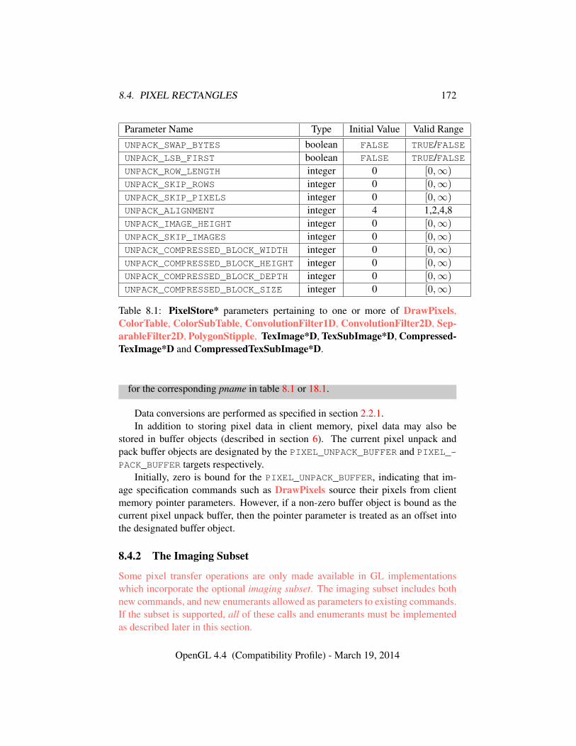
8.4. PIXEL RECTANGLES 172
Parameter Name Type Initial Value Valid RangeUNPACK_SWAP_BYTES boolean FALSE TRUE/FALSEUNPACK_LSB_FIRST boolean FALSE TRUE/FALSEUNPACK_ROW_LENGTH integer 0 [0,∞)
UNPACK_SKIP_ROWS integer 0 [0,∞)
UNPACK_SKIP_PIXELS integer 0 [0,∞)
UNPACK_ALIGNMENT integer 4 1,2,4,8UNPACK_IMAGE_HEIGHT integer 0 [0,∞)
UNPACK_SKIP_IMAGES integer 0 [0,∞)
UNPACK_COMPRESSED_BLOCK_WIDTH integer 0 [0,∞)
UNPACK_COMPRESSED_BLOCK_HEIGHT integer 0 [0,∞)
UNPACK_COMPRESSED_BLOCK_DEPTH integer 0 [0,∞)
UNPACK_COMPRESSED_BLOCK_SIZE integer 0 [0,∞)
Table 8.1: PixelStore* parameters pertaining to one or more of DrawPixels,ColorTable, ColorSubTable, ConvolutionFilter1D, ConvolutionFilter2D, Sep-arableFilter2D, PolygonStipple, TexImage*D, TexSubImage*D, Compressed-TexImage*D and CompressedTexSubImage*D.
for the corresponding pname in table 8.1 or 18.1.
Data conversions are performed as specified in section 2.2.1.In addition to storing pixel data in client memory, pixel data may also be
stored in buffer objects (described in section 6). The current pixel unpack andpack buffer objects are designated by the PIXEL_UNPACK_BUFFER and PIXEL_-
PACK_BUFFER targets respectively.Initially, zero is bound for the PIXEL_UNPACK_BUFFER, indicating that im-
age specification commands such as DrawPixels source their pixels from clientmemory pointer parameters. However, if a non-zero buffer object is bound as thecurrent pixel unpack buffer, then the pointer parameter is treated as an offset intothe designated buffer object.
8.4.2 The Imaging Subset
Some pixel transfer operations are only made available in GL implementationswhich incorporate the optional imaging subset. The imaging subset includes bothnew commands, and new enumerants allowed as parameters to existing commands.If the subset is supported, all of these calls and enumerants must be implementedas described later in this section.
OpenGL 4.4 (Compatibility Profile) - March 19, 2014
8.4. PIXEL RECTANGLES 173
If the imaging subset is not supported, calling any unsupported command gen-erates an INVALID_OPERATION error, and using any of the new enumerants gen-erates an INVALID_ENUM error.
The individual operations available only in the imaging subset are described insection 8.4.3. Imaging subset operations include:
• Color tables, including all commands and enumerants described in sub-sections Color Table Specification, Alternate Color Table SpecificationCommands, Color Table State and Proxy State, Color Table Lookup,Post Convolution Color Table Lookup, and Post Color Matrix Color Ta-ble Lookup, as well as the query commands described in section 8.4.3.4.
• Convolution, including all commands and enumerants described in sub-sections Convolution Filter Specification, Alternate Convolution FilterSpecification Commands, and Convolution, as well as the query com-mands described in section 8.4.3.8.
• Color matrix, including all commands and enumerants described in subsec-tions Color Matrix Specification and Color Matrix Transformation, aswell as the simple query commands described in section 8.4.3.11.
• Histogram and minmax, including all commands and enumerants de-scribed in subsections Histogram Table Specification, Histogram Stateand Proxy State, Histogram, Minmax Table Specification, and Min-max, as well as the query commands described in section 8.4.3.13 and sec-tion 8.4.3.16.
The imaging subset is supported only if the EXTENSIONS string includesthe substring ”GL_ARB_imaging” Querying EXTENSIONS is described in sec-tion 22.2.
If the imaging subset is not supported, the related pixel transfer operations arenot performed; pixels are passed unchanged to the next operation.
8.4.3 Pixel Transfer Modes
Pixel transfer modes affect the operation of DrawPixels (section 18.1), ReadPix-els (section 18.2), and CopyPixels (section 18.3) at the time when one of thesecommands is executed (which may differ from the time the command is issued).Some pixel transfer modes are set with
void PixelTransfer{if}( enum param, T value );
OpenGL 4.4 (Compatibility Profile) - March 19, 2014
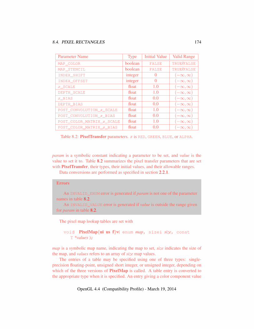
8.4. PIXEL RECTANGLES 174
Parameter Name Type Initial Value Valid RangeMAP_COLOR boolean FALSE TRUE/FALSEMAP_STENCIL boolean FALSE TRUE/FALSEINDEX_SHIFT integer 0 (−∞,∞)
INDEX_OFFSET integer 0 (−∞,∞)
x_SCALE float 1.0 (−∞,∞)
DEPTH_SCALE float 1.0 (−∞,∞)
x_BIAS float 0.0 (−∞,∞)
DEPTH_BIAS float 0.0 (−∞,∞)
POST_CONVOLUTION_x_SCALE float 1.0 (−∞,∞)
POST_CONVOLUTION_x_BIAS float 0.0 (−∞,∞)
POST_COLOR_MATRIX_x_SCALE float 1.0 (−∞,∞)
POST_COLOR_MATRIX_x_BIAS float 0.0 (−∞,∞)
Table 8.2: PixelTransfer parameters. x is RED, GREEN, BLUE, or ALPHA.
param is a symbolic constant indicating a parameter to be set, and value is thevalue to set it to. Table 8.2 summarizes the pixel transfer parameters that are setwith PixelTransfer, their types, their initial values, and their allowable ranges.
Data conversions are performed as specified in section 2.2.1.
Errors
An INVALID_ENUM error is generated if param is not one of the parameternames in table 8.2.
An INVALID_VALUE error is generated if value is outside the range givenfor param in table 8.2.
The pixel map lookup tables are set with
void PixelMap{ui us f}v( enum map, sizei size, constT *values );
map is a symbolic map name, indicating the map to set, size indicates the size ofthe map, and values refers to an array of size map values.
The entries of a table may be specified using one of three types: single-precision floating-point, unsigned short integer, or unsigned integer, depending onwhich of the three versions of PixelMap is called. A table entry is converted tothe appropriate type when it is specified. An entry giving a color component value
OpenGL 4.4 (Compatibility Profile) - March 19, 2014
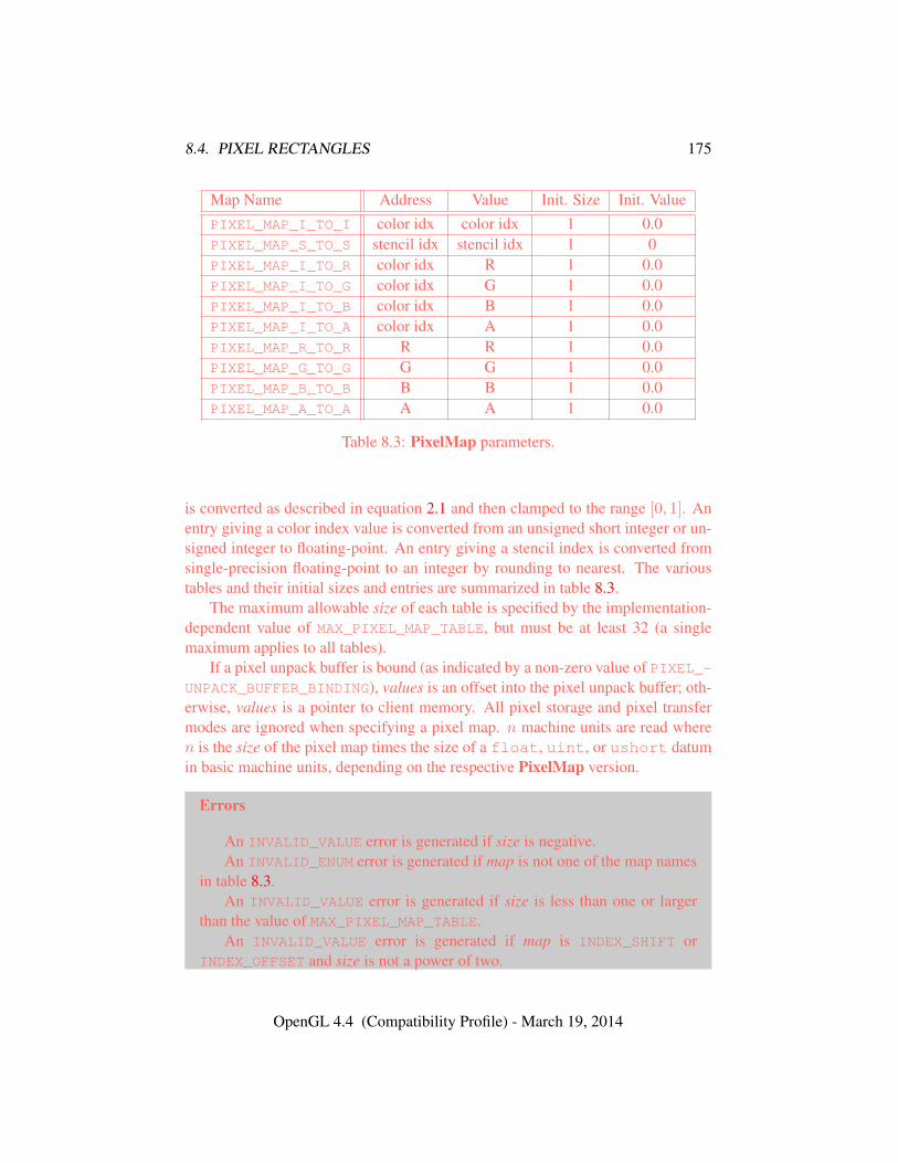
8.4. PIXEL RECTANGLES 175
Map Name Address Value Init. Size Init. ValuePIXEL_MAP_I_TO_I color idx color idx 1 0.0PIXEL_MAP_S_TO_S stencil idx stencil idx 1 0PIXEL_MAP_I_TO_R color idx R 1 0.0PIXEL_MAP_I_TO_G color idx G 1 0.0PIXEL_MAP_I_TO_B color idx B 1 0.0PIXEL_MAP_I_TO_A color idx A 1 0.0PIXEL_MAP_R_TO_R R R 1 0.0PIXEL_MAP_G_TO_G G G 1 0.0PIXEL_MAP_B_TO_B B B 1 0.0PIXEL_MAP_A_TO_A A A 1 0.0
Table 8.3: PixelMap parameters.
is converted as described in equation 2.1 and then clamped to the range [0, 1]. Anentry giving a color index value is converted from an unsigned short integer or un-signed integer to floating-point. An entry giving a stencil index is converted fromsingle-precision floating-point to an integer by rounding to nearest. The varioustables and their initial sizes and entries are summarized in table 8.3.
The maximum allowable size of each table is specified by the implementation-dependent value of MAX_PIXEL_MAP_TABLE, but must be at least 32 (a singlemaximum applies to all tables).
If a pixel unpack buffer is bound (as indicated by a non-zero value of PIXEL_-UNPACK_BUFFER_BINDING), values is an offset into the pixel unpack buffer; oth-erwise, values is a pointer to client memory. All pixel storage and pixel transfermodes are ignored when specifying a pixel map. n machine units are read wheren is the size of the pixel map times the size of a float, uint, or ushort datumin basic machine units, depending on the respective PixelMap version.
Errors
An INVALID_VALUE error is generated if size is negative.An INVALID_ENUM error is generated if map is not one of the map names
in table 8.3.An INVALID_VALUE error is generated if size is less than one or larger
than the value of MAX_PIXEL_MAP_TABLE.An INVALID_VALUE error is generated if map is INDEX_SHIFT or
INDEX_OFFSET and size is not a power of two.
OpenGL 4.4 (Compatibility Profile) - March 19, 2014
8.4. PIXEL RECTANGLES 176
An INVALID_OPERATION error is generated if a pixel unpack buffer ob-ject is bound and data+ n is greater than the size of the pixel buffer.
An INVALID_OPERATION error is generated if a pixel unpack buffer ob-ject is bound and values is not evenly divisible by the number of basic machineunits needed to store in memory a float, uint, or ushort datum depend-ing on their respective PixelMap version.
8.4.3.1 Pixel Map Queries
The command
void GetPixelMap{ui us f}v( enum map, T *data );
returns all values in the pixel map map in data. map must be a map name fromtable 8.3. GetPixelMapuiv and GetPixelMapusv convert floating-point pixel mapvalues to integers according to the UNSIGNED_INT and UNSIGNED_SHORT entries,respectively, of table 18.2.
If a pixel pack buffer is bound (as indicated by a non-zero value of PIXEL_-PACK_BUFFER_BINDING), data is an offset into the pixel pack buffer; otherwise,data is a pointer to client memory. All pixel storage and pixel transfer modes areignored when returning a pixel map. nmachine units are written where n is the sizeof the pixel map times the size of FLOAT, UNSIGNED_INT, or UNSIGNED_SHORTrespectively in basic machine units.
Errors
An INVALID_OPERATION error is generated if a pixel pack buffer objectis bound and data+ n is greater than the size of the pixel buffer.
An INVALID_OPERATION error is generated if a pixel pack buffer objectis bound and data is not evenly divisible by the number of basic machine unitsneeded to store in memory a FLOAT, UNSIGNED_INT, or UNSIGNED_SHORTrespectively.
The same errors generated by PixelMap*v for invalid values of map aregenerated by GetPixelMap*.
8.4.3.2 Color Table Specification
Color lookup tables are specified with
void ColorTable( enum target, enum internalformat,sizei width, enum format, enum type, constvoid *data );
OpenGL 4.4 (Compatibility Profile) - March 19, 2014
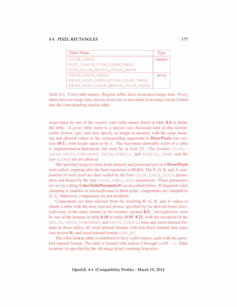
8.4. PIXEL RECTANGLES 177
Table Name TypeCOLOR_TABLE regularPOST_CONVOLUTION_COLOR_TABLE
POST_COLOR_MATRIX_COLOR_TABLE
PROXY_COLOR_TABLE proxyPROXY_POST_CONVOLUTION_COLOR_TABLE
PROXY_POST_COLOR_MATRIX_COLOR_TABLE
Table 8.4: Color table names. Regular tables have associated image data. Proxytables have no image data, and are used only to determine if an image can be loadedinto the corresponding regular table.
target must be one of the regular color table names listed in table 8.4 to definethe table. A proxy table name is a special case discussed later in this section.width, format, type, and data specify an image in memory with the same mean-ing and allowed values as the corresponding arguments to DrawPixels (see sec-tion 18.1), with height taken to be 1. The maximum allowable width of a tableis implementation-dependent, but must be at least 32. The formats COLOR_-
INDEX, DEPTH_COMPONENT, DEPTH_STENCIL, and STENCIL_INDEX and thetype BITMAP are not allowed.
The specified image is taken from memory and processed just as if DrawPixelswere called, stopping after the final expansion to RGBA. The R, G, B, and A com-ponents of each pixel are then scaled by the four COLOR_TABLE_SCALE param-eters and biased by the four COLOR_TABLE_BIAS parameters. These parametersare set by calling ColorTableParameterfv as described below. If fragment colorclamping is enabled or internalformat is fixed-point, components are clamped to[0, 1]. Otherwise, components are not modified.
Components are then selected from the resulting R, G, B, and A values toobtain a table with the base internal format specified by (or derived from) inter-nalformat, in the same manner as for textures (section 8.5). internalformat mustbe one of the formats in table 8.18 or tables 8.19- 8.21, with the exception of theRED, RG, DEPTH_COMPONENT, and DEPTH_STENCIL base and sized internal for-mats in those tables, all sized internal formats with non-fixed internal data types(see section 8), and sized internal format RGB9_E5.
The color lookup table is redefined to have width entries, each with the speci-fied internal format. The table is formed with indices 0 through width − 1. Tablelocation i is specified by the ith image pixel, counting from zero.
OpenGL 4.4 (Compatibility Profile) - March 19, 2014
8.4. PIXEL RECTANGLES 178
Errors
An INVALID_ENUM error is generated if target is not a regular color tablename from table 8.4.
An INVALID_VALUE error is generated if width is not zero or a non-negative power of two.
A TABLE_TOO_LARGE error is generated if the specified color lookup ta-ble is too large for the implementation.
The scale and bias parameters for a table are specified by calling
void ColorTableParameter{if}v( enum target, enum pname,const T *params );
target must be a regular color table name. pname is one of COLOR_TABLE_SCALEor COLOR_TABLE_BIAS. params points to an array of four values: red, green, blue,and alpha, in that order.
Errors
An INVALID_ENUM error is generated if target is not a regular color tablename from table 8.4.
An INVALID_ENUM error is generated if pname is not COLOR_TABLE_-SCALE or COLOR_TABLE_BIAS.
Data conversions are performed as specified in section 2.2.1.A GL implementation may vary its allocation of internal component resolution
based on any ColorTable parameter, but the allocation must not be a function ofany other factor, and cannot be changed once it is established. Allocations mustbe invariant; the same allocation must be made each time a color table is specifiedwith the same parameter values. These allocation rules also apply to proxy colortables, which are described later in this section.
8.4.3.3 Alternate Color Table Specification Commands
Color tables may also be specified using image data taken directly from the frame-buffer, and portions of existing tables may be respecified.
The command
void CopyColorTable( enum target, enum internalformat,int x, int y, sizei width );
OpenGL 4.4 (Compatibility Profile) - March 19, 2014
8.4. PIXEL RECTANGLES 179
defines a color table in exactly the manner of ColorTable, except that table dataare taken from the framebuffer, rather than from client memory. target must be aregular color table name. x, y, and width correspond precisely to the correspondingarguments of CopyPixels (refer to section 18.3); they specify the image’s widthand the lower left (x, y) coordinates of the framebuffer region to be copied. Theimage is taken from the framebuffer exactly as if these arguments were passed toCopyPixels with argument type set to COLOR and height set to 1, stopping after thefinal expansion to RGBA.
Subsequent processing is identical to that described for ColorTable, begin-ning with scaling by COLOR_TABLE_SCALE. Parameters target, internalformat andwidth are specified using the same values, with the same meanings, as the corre-sponding arguments of ColorTable. format is taken to be RGBA.
Errors
An INVALID_ENUM error is generated if target is not a regular color tablename from table 8.4.
An INVALID_VALUE error is generated if width is negative.An INVALID_FRAMEBUFFER_OPERATION error is generated if the object
bound to READ_FRAMEBUFFER_BINDING is not framebuffer complete (seesection 9.4.2).
Two additional commands,
void ColorSubTable( enum target, sizei start, sizei count,enum format, enum type, const void *data );
void CopyColorSubTable( enum target, sizei start, int x,int y, sizei count );
respecify only a portion of an existing color table. No change is made to the inter-nalformat or width parameters of the specified color table, nor is any change madeto table entries outside the specified portion. target must be a regular color tablename.
ColorSubTable arguments format, type, and data match the corresponding ar-guments to ColorTable, meaning that they are specified using the same values,and have the same meanings. Likewise, CopyColorSubTable arguments x, y, andcount match the x, y, and width arguments of CopyColorTable. Both of the Color-SubTable commands interpret and process pixel groups in exactly the manner oftheir ColorTable counterparts, except that the assignment of R, G, B, and A pixelgroup values to the color table components is controlled by the internalformat ofthe table, not by an argument to the command.
OpenGL 4.4 (Compatibility Profile) - March 19, 2014
8.4. PIXEL RECTANGLES 180
Arguments start and count of ColorSubTable and CopyColorSubTable spec-ify a subregion of the color table starting at index start and ending at indexstart + count − 1. Counting from zero, the nth pixel group is assigned to thetable entry with index count+ n.
Errors
An INVALID_ENUM error is generated if target is not a regular color tablename from table 8.4.
An INVALID_FRAMEBUFFER_OPERATION error is generated by Copy-ColorSubTable if the object bound to READ_FRAMEBUFFER_BINDING is notframebuffer complete (see section 9.4.2).
An INVALID_VALUE error is generated if start or count is negative, or ifstart+ count is greater than the width of the color table specified by target.
8.4.3.4 Color Table Query
The current contents of a color table are queried using
void GetColorTable( enum target, enum format, enum type,void *table );
target must be one of the regular color table names listed in table 8.4. formatmust be a pixel format from table 8.5 and type must be a data type from table 8.6.The one-dimensional color table image is returned to pixel pack buffer or clientmemory starting at table. No pixel transfer operations are performed on this image,but pixel storage modes that are applicable to ReadPixels are performed. Colorcomponents that are requested in the specified format, but which are not included inthe internal format of the color lookup table, are returned as zero. The assignmentsof internal color components to the components requested by format are describedin table 8.25.
The command
void GetColorTableParameter{if}v( enum target,enum pname, T params );
is used for integer and floating-point query.target must be one of the regular or proxy color table names listed in ta-
ble 8.4. pname is one of COLOR_TABLE_SCALE, COLOR_TABLE_BIAS, COLOR_-TABLE_FORMAT, COLOR_TABLE_WIDTH, COLOR_TABLE_RED_SIZE, COLOR_-TABLE_GREEN_SIZE, COLOR_TABLE_BLUE_SIZE, COLOR_TABLE_ALPHA_-
OpenGL 4.4 (Compatibility Profile) - March 19, 2014
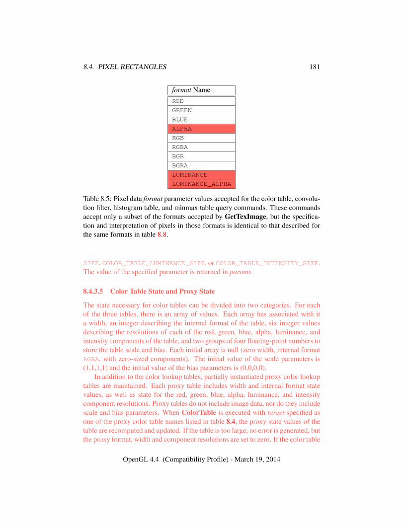
8.4. PIXEL RECTANGLES 181
format NameRED
GREEN
BLUE
ALPHA
RGB
RGBA
BGR
BGRA
LUMINANCE
LUMINANCE_ALPHA
Table 8.5: Pixel data format parameter values accepted for the color table, convolu-tion filter, histogram table, and minmax table query commands. These commandsaccept only a subset of the formats accepted by GetTexImage, but the specifica-tion and interpretation of pixels in those formats is identical to that described forthe same formats in table 8.8.
SIZE, COLOR_TABLE_LUMINANCE_SIZE, or COLOR_TABLE_INTENSITY_SIZE.The value of the specified parameter is returned in params.
8.4.3.5 Color Table State and Proxy State
The state necessary for color tables can be divided into two categories. For eachof the three tables, there is an array of values. Each array has associated with ita width, an integer describing the internal format of the table, six integer valuesdescribing the resolutions of each of the red, green, blue, alpha, luminance, andintensity components of the table, and two groups of four floating-point numbers tostore the table scale and bias. Each initial array is null (zero width, internal formatRGBA, with zero-sized components). The initial value of the scale parameters is(1,1,1,1) and the initial value of the bias parameters is (0,0,0,0).
In addition to the color lookup tables, partially instantiated proxy color lookuptables are maintained. Each proxy table includes width and internal format statevalues, as well as state for the red, green, blue, alpha, luminance, and intensitycomponent resolutions. Proxy tables do not include image data, nor do they includescale and bias parameters. When ColorTable is executed with target specified asone of the proxy color table names listed in table 8.4, the proxy state values of thetable are recomputed and updated. If the table is too large, no error is generated, butthe proxy format, width and component resolutions are set to zero. If the color table
OpenGL 4.4 (Compatibility Profile) - March 19, 2014
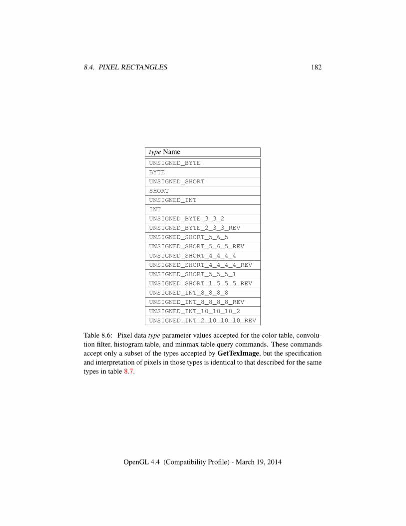
8.4. PIXEL RECTANGLES 182
type NameUNSIGNED_BYTE
BYTE
UNSIGNED_SHORT
SHORT
UNSIGNED_INT
INT
UNSIGNED_BYTE_3_3_2
UNSIGNED_BYTE_2_3_3_REV
UNSIGNED_SHORT_5_6_5
UNSIGNED_SHORT_5_6_5_REV
UNSIGNED_SHORT_4_4_4_4
UNSIGNED_SHORT_4_4_4_4_REV
UNSIGNED_SHORT_5_5_5_1
UNSIGNED_SHORT_1_5_5_5_REV
UNSIGNED_INT_8_8_8_8
UNSIGNED_INT_8_8_8_8_REV
UNSIGNED_INT_10_10_10_2
UNSIGNED_INT_2_10_10_10_REV
Table 8.6: Pixel data type parameter values accepted for the color table, convolu-tion filter, histogram table, and minmax table query commands. These commandsaccept only a subset of the types accepted by GetTexImage, but the specificationand interpretation of pixels in those types is identical to that described for the sametypes in table 8.7.
OpenGL 4.4 (Compatibility Profile) - March 19, 2014
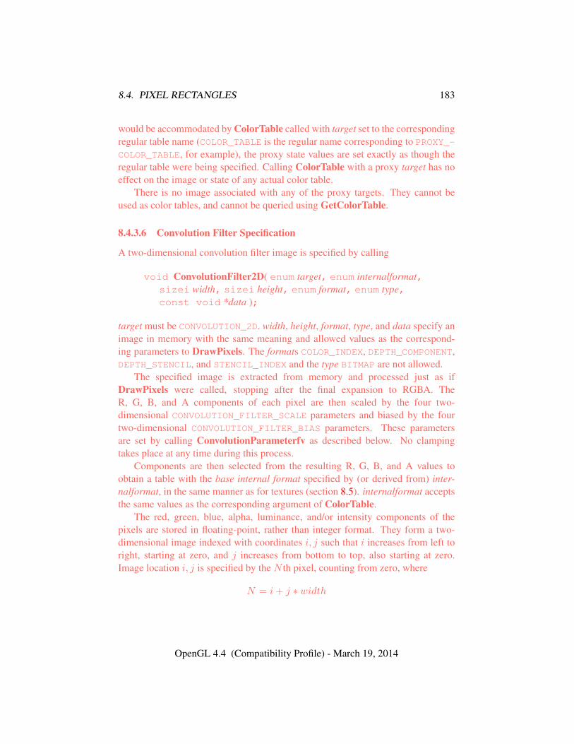
8.4. PIXEL RECTANGLES 183
would be accommodated by ColorTable called with target set to the correspondingregular table name (COLOR_TABLE is the regular name corresponding to PROXY_-COLOR_TABLE, for example), the proxy state values are set exactly as though theregular table were being specified. Calling ColorTable with a proxy target has noeffect on the image or state of any actual color table.
There is no image associated with any of the proxy targets. They cannot beused as color tables, and cannot be queried using GetColorTable.
8.4.3.6 Convolution Filter Specification
A two-dimensional convolution filter image is specified by calling
void ConvolutionFilter2D( enum target, enum internalformat,sizei width, sizei height, enum format, enum type,const void *data );
target must be CONVOLUTION_2D. width, height, format, type, and data specify animage in memory with the same meaning and allowed values as the correspond-ing parameters to DrawPixels. The formats COLOR_INDEX, DEPTH_COMPONENT,DEPTH_STENCIL, and STENCIL_INDEX and the type BITMAP are not allowed.
The specified image is extracted from memory and processed just as ifDrawPixels were called, stopping after the final expansion to RGBA. TheR, G, B, and A components of each pixel are then scaled by the four two-dimensional CONVOLUTION_FILTER_SCALE parameters and biased by the fourtwo-dimensional CONVOLUTION_FILTER_BIAS parameters. These parametersare set by calling ConvolutionParameterfv as described below. No clampingtakes place at any time during this process.
Components are then selected from the resulting R, G, B, and A values toobtain a table with the base internal format specified by (or derived from) inter-nalformat, in the same manner as for textures (section 8.5). internalformat acceptsthe same values as the corresponding argument of ColorTable.
The red, green, blue, alpha, luminance, and/or intensity components of thepixels are stored in floating-point, rather than integer format. They form a two-dimensional image indexed with coordinates i, j such that i increases from left toright, starting at zero, and j increases from bottom to top, also starting at zero.Image location i, j is specified by the N th pixel, counting from zero, where
N = i+ j ∗ width
OpenGL 4.4 (Compatibility Profile) - March 19, 2014

8.4. PIXEL RECTANGLES 184
Errors
An INVALID_VALUE error is generated if width or height is negative, orgreater than the maximum supported width or height, which may be queriedby calling GetConvolutionParameteriv with target CONVOLUTION_2D andpname MAX_CONVOLUTION_WIDTH or MAX_CONVOLUTION_HEIGHT, respec-tively.
The scale and bias parameters for a two-dimensional filter are specified bycalling
void ConvolutionParameter{if}v( enum target, enum pname,const T *params );
with target CONVOLUTION_2D. pname is one of CONVOLUTION_FILTER_SCALEor CONVOLUTION_FILTER_BIAS. params points to an array of four values: red,green, blue, and alpha, in that order.
Data conversions are performed as specified in section 2.2.1.A one-dimensional convolution filter is defined using
void ConvolutionFilter1D( enum target, enum internalformat,sizei width, enum format, enum type, constvoid *data );
target must be CONVOLUTION_1D. internalformat, width, format, and type haveidentical semantics and accept the same values as do their two-dimensional coun-terparts. data must point to a one-dimensional image, however.
The image is extracted from memory and processed as if ConvolutionFilter2Dwere called with a height of 1, except that it is scaled and biased by the one-dimensional CONVOLUTION_FILTER_SCALE and CONVOLUTION_FILTER_BIAS
parameters. These parameters are specified exactly as the two-dimensional param-eters, except that ConvolutionParameterfv is called with target CONVOLUTION_-1D.
The image is formed with coordinates i such that i increases from left to right,starting at zero. Image location i is specified by the ith pixel, counting from zero.
Errors
An INVALID_VALUE error is generated if width is negative, or greater thanthe maximum supported value width, which may be queried by calling Get-
OpenGL 4.4 (Compatibility Profile) - March 19, 2014
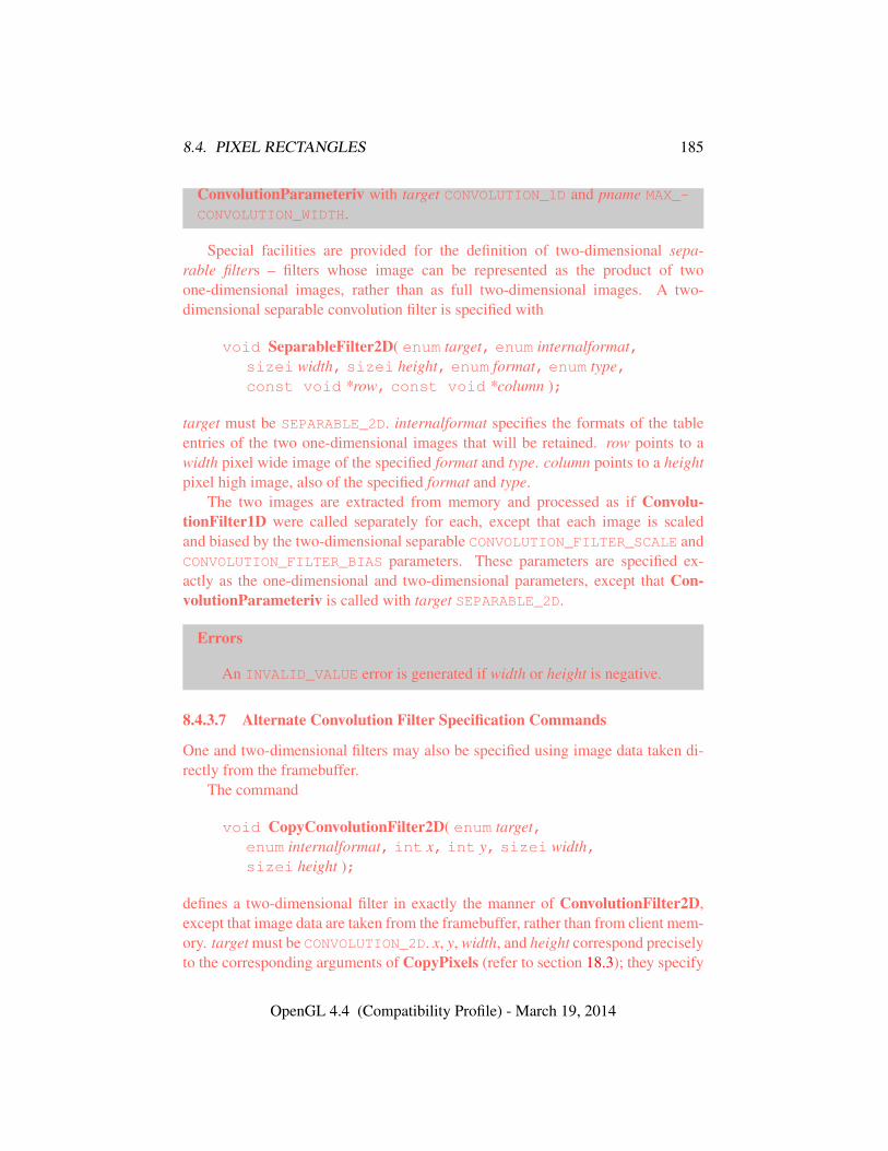
8.4. PIXEL RECTANGLES 185
ConvolutionParameteriv with target CONVOLUTION_1D and pname MAX_-
CONVOLUTION_WIDTH.
Special facilities are provided for the definition of two-dimensional sepa-rable filters – filters whose image can be represented as the product of twoone-dimensional images, rather than as full two-dimensional images. A two-dimensional separable convolution filter is specified with
void SeparableFilter2D( enum target, enum internalformat,sizei width, sizei height, enum format, enum type,const void *row, const void *column );
target must be SEPARABLE_2D. internalformat specifies the formats of the tableentries of the two one-dimensional images that will be retained. row points to awidth pixel wide image of the specified format and type. column points to a heightpixel high image, also of the specified format and type.
The two images are extracted from memory and processed as if Convolu-tionFilter1D were called separately for each, except that each image is scaledand biased by the two-dimensional separable CONVOLUTION_FILTER_SCALE andCONVOLUTION_FILTER_BIAS parameters. These parameters are specified ex-actly as the one-dimensional and two-dimensional parameters, except that Con-volutionParameteriv is called with target SEPARABLE_2D.
Errors
An INVALID_VALUE error is generated if width or height is negative.
8.4.3.7 Alternate Convolution Filter Specification Commands
One and two-dimensional filters may also be specified using image data taken di-rectly from the framebuffer.
The command
void CopyConvolutionFilter2D( enum target,enum internalformat, int x, int y, sizei width,sizei height );
defines a two-dimensional filter in exactly the manner of ConvolutionFilter2D,except that image data are taken from the framebuffer, rather than from client mem-ory. target must be CONVOLUTION_2D. x, y, width, and height correspond preciselyto the corresponding arguments of CopyPixels (refer to section 18.3); they specify
OpenGL 4.4 (Compatibility Profile) - March 19, 2014
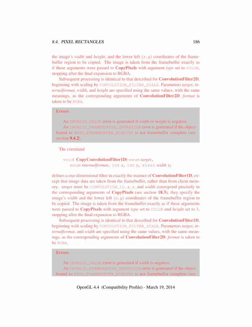
8.4. PIXEL RECTANGLES 186
the image’s width and height, and the lower left (x, y) coordinates of the frame-buffer region to be copied. The image is taken from the framebuffer exactly asif these arguments were passed to CopyPixels with argument type set to COLOR,stopping after the final expansion to RGBA.
Subsequent processing is identical to that described for ConvolutionFilter2D,beginning with scaling by CONVOLUTION_FILTER_SCALE. Parameters target, in-ternalformat, width, and height are specified using the same values, with the samemeanings, as the corresponding arguments of ConvolutionFilter2D. format istaken to be RGBA.
Errors
An INVALID_VALUE error is generated if width or height is negative.An INVALID_FRAMEBUFFER_OPERATION error is generated if the object
bound to READ_FRAMEBUFFER_BINDING is not framebuffer complete (seesection 9.4.2).
The command
void CopyConvolutionFilter1D( enum target,enum internalformat, int x, int y, sizei width );
defines a one-dimensional filter in exactly the manner of ConvolutionFilter1D, ex-cept that image data are taken from the framebuffer, rather than from client mem-ory. target must be CONVOLUTION_1D. x, y, and width correspond precisely tothe corresponding arguments of CopyPixels (see section 18.3); they specify theimage’s width and the lower left (x, y) coordinates of the framebuffer region tobe copied. The image is taken from the framebuffer exactly as if these argumentswere passed to CopyPixels with argument type set to COLOR and height set to 1,stopping after the final expansion to RGBA.
Subsequent processing is identical to that described for ConvolutionFilter1D,beginning with scaling by CONVOLUTION_FILTER_SCALE. Parameters target, in-ternalformat, and width are specified using the same values, with the same mean-ings, as the corresponding arguments of ConvolutionFilter2D. format is taken tobe RGBA.
Errors
An INVALID_VALUE error is generated if width is negative.An INVALID_FRAMEBUFFER_OPERATION error is generated if the object
bound to READ_FRAMEBUFFER_BINDING is not framebuffer complete (see
OpenGL 4.4 (Compatibility Profile) - March 19, 2014
8.4. PIXEL RECTANGLES 187
section 9.4.2).
8.4.3.8 Convolution Query
The contents of a convolution filter image are queried with the command
void GetConvolutionFilter( enum target, enum format,enum type, void *image );
target must be CONVOLUTION_1D or CONVOLUTION_2D. format must be a pixelformat from table 8.5 and type must be a data type from table 8.6. The one-ortwo-dimensional image is returned to pixel pack buffer or client memory startingat image. Pixel processing and component mapping are identical to those of Get-TexImage.
The current contents of a separable filter image are queried using
void GetSeparableFilter( enum target, enum format,enum type, void *row, void *column, void *span );
target must be SEPARABLE_2D. format must be a pixel format from table 8.5 andtype must be a data type from table 8.6. The row and column images are returnedto pixel pack buffer or client memory starting at row and column respectively. spanis unused. Pixel processing and component mapping are identical to those of Get-TexImage.
The commands
void GetConvolutionParameter{if}v( enum target,enum pname, T *params );
are used for integer and floating-point query. target must be CONVOLUTION_1D,CONVOLUTION_2D, or SEPARABLE_2D. pname is one of CONVOLUTION_-
BORDER_COLOR, CONVOLUTION_BORDER_MODE, CONVOLUTION_-
FILTER_SCALE, CONVOLUTION_FILTER_BIAS, CONVOLUTION_FORMAT,CONVOLUTION_WIDTH, CONVOLUTION_HEIGHT, MAX_CONVOLUTION_WIDTH,or MAX_CONVOLUTION_HEIGHT. The value of the specified parameter is returnedin params.
8.4.3.9 Convolution Filter State
The required state for convolution filters includes a one-dimensional image array,two one-dimensional image arrays for the separable filter, and a two-dimensional
OpenGL 4.4 (Compatibility Profile) - March 19, 2014
8.4. PIXEL RECTANGLES 188
image array. Each filter has associated with it a width and height (two-dimensionaland separable only), an integer describing the internal format of the filter, and twogroups of four floating-point numbers to store the filter scale and bias.
Each initial convolution filter is null (zero width and height, internal formatRGBA, with zero-sized components). The initial value of all scale parameters is(1,1,1,1) and the initial value of all bias parameters is (0,0,0,0).
8.4.3.10 Color Matrix Specification
Setting the matrix mode to COLOR causes the matrix operations described in sec-tion 12.1.1 to apply to the top matrix on the color matrix stack. All matrix opera-tions have the same effect on the color matrix as they do on the other matrices.
8.4.3.11 Color Matrix Query
The scale and bias variables are queried using GetFloatv with pname set to theappropriate variable name. The top matrix on the color matrix stack is returnedby GetFloatv called with pname set to COLOR_MATRIX or TRANSPOSE_COLOR_-MATRIX. The depth of the color matrix stack, and the maximum depth of the colormatrix stack, are queried with GetIntegerv, setting pname to COLOR_MATRIX_-
STACK_DEPTH and MAX_COLOR_MATRIX_STACK_DEPTH respectively.
8.4.3.12 Histogram Table Specification
The histogram table is specified with
void Histogram( enum target, sizei width,enum internalformat, boolean sink );
target must be HISTOGRAM if a histogram table is to be specified. target valuePROXY_HISTOGRAM is a special case discussed later in this section. width speci-fies the number of entries in the histogram table, and internalformat specifies theformat of each table entry. The maximum allowable width of the histogram tableis implementation-dependent, but must be at least 32. sink specifies whether pixelgroups will be consumed by the histogram operation (TRUE) or passed on to theminmax operation (FALSE).
The specified histogram table is redefined to have width entries, each with thespecified internal format. The entries are indexed 0 through width − 1. Eachcomponent in each entry is set to zero. The values in the previous histogram table,if any, are lost.
OpenGL 4.4 (Compatibility Profile) - March 19, 2014
8.4. PIXEL RECTANGLES 189
A GL implementation may vary its allocation of internal component resolutionbased on any Histogram parameter, but the allocation must not be a function of anyother factor, and cannot be changed once it is established. In particular, allocationsmust be invariant; the same allocation must be made each time a histogram isspecified with the same parameter values. These allocation rules also apply to theproxy histogram, which is described later in this section.
Errors
internalformat accepts the same values as the corresponding argument ofColorTable, with the exception of the values 1, 2, 3, and 4.
An INVALID_VALUE error is generated if width is not zero or a non-negative power of two.
A TABLE_TOO_LARGE error is generated if the specified histogram tableis too large for the implementation.
8.4.3.13 Histogram Query
The current contents of the histogram table are queried using
void GetHistogram( enum target, boolean reset,enum format, enum type, void* values );
target must be HISTOGRAM. format must be a pixel format from table 8.5 and typemust be a data type from table 8.6. The one-dimensional histogram table image isreturned to pixel pack buffer or client memory starting at values. Pixel processingand component mapping are identical to those of GetTexImage, except that insteadof applying the Final Conversion pixel storage mode, component values are simplyclamped to the range of the target data type.
If reset is TRUE, then all counters of all elements of the histogram are reset tozero. Counters are reset whether returned or not.
No counters are modified if reset is FALSE.The command
void ResetHistogram( enum target );
resets all counters of all elements of the histogram table to zero. target must beHISTOGRAM.
It is not an error to reset or query the contents of a histogram table with zeroentries.
The commands
OpenGL 4.4 (Compatibility Profile) - March 19, 2014
8.4. PIXEL RECTANGLES 190
void GetHistogramParameter{if}v( enum target,enum pname, T *params );
are used for integer and floating-point query. target must be HISTOGRAM orPROXY_HISTOGRAM. pname is one of HISTOGRAM_FORMAT, HISTOGRAM_WIDTH,HISTOGRAM_RED_SIZE, HISTOGRAM_GREEN_SIZE, HISTOGRAM_BLUE_SIZE,HISTOGRAM_ALPHA_SIZE, or HISTOGRAM_LUMINANCE_SIZE. pname may beHISTOGRAM_SINK only for target HISTOGRAM. The value of the specified param-eter is returned in params.
8.4.3.14 Histogram State and Proxy State
The state necessary for histogram operation is an array of values, with which isassociated a width, an integer describing the internal format of the histogram, fiveinteger values describing the resolutions of each of the red, green, blue, alpha,and luminance components of the table, and a flag indicating whether or not pixelgroups are consumed by the operation. The initial array is null (zero width, internalformat RGBA, with zero-sized components). The initial value of the flag is false.
In addition to the histogram table, a partially instantiated proxy histogram tableis maintained. It includes width, internal format, and red, green, blue, alpha, andluminance component resolutions. The proxy table does not include image data orthe flag. When Histogram is executed with target set to PROXY_HISTOGRAM, theproxy state values are recomputed and updated. If the histogram array is too large,no error is generated, but the proxy format, width, and component resolutions areset to zero. If the histogram table would be accomodated by Histogram calledwith target set to HISTOGRAM, the proxy state values are set exactly as thoughthe actual histogram table were being specified. Calling Histogram with targetPROXY_HISTOGRAM has no effect on the actual histogram table.
There is no image associated with PROXY_HISTOGRAM. It cannot be used as ahistogram, and its image cannot be queried using GetHistogram.
8.4.3.15 Minmax Table Specification
The minmax table is specified with
void Minmax( enum target, enum internalformat,boolean sink );
target must be MINMAX. internalformat specifies the format of the table entries.sink specifies whether pixel groups will be consumed by the minmax operation(TRUE) or passed on to final conversion (FALSE).
OpenGL 4.4 (Compatibility Profile) - March 19, 2014
8.4. PIXEL RECTANGLES 191
internalformat accepts the same values as the corresponding argument of Col-orTable, with the exception of the values 1, 2, 3, and 4, as well as the INTENSITYbase and sized internal formats. The resulting table always has 2 entries, each withvalues corresponding only to the components of the internal format.
The state necessary for minmax operation is a table containing two elements(the first element stores the minimum values, the second stores the maximum val-ues), an integer describing the internal format of the table, and a flag indicatingwhether or not pixel groups are consumed by the operation. The initial state isa minimum table entry set to the maximum representable value and a maximumtable entry set to the minimum representable value. Internal format is set to RGBA
and the initial value of the flag is false.
8.4.3.16 Minmax Query
The current contents of the minmax table are queried using
void GetMinmax( enum target, boolean reset, enum format,enum type, void* values );
target must be MINMAX. format must be a pixel format from table 8.5 and type mustbe a data type from table 8.6. A one-dimensional image of width 2 is returnedto pixel pack buffer or client memory starting at values. Pixel processing andcomponent mapping are identical to those of GetTexImage.
If reset is TRUE, then each minimum value is reset to the maximum repre-sentable value, and each maximum value is reset to the minimum representablevalue. All values are reset, whether returned or not.
No values are modified if reset is FALSE.The command
void ResetMinmax( enum target );
resets all minimum and maximum values of target to to their maximum and mini-mum representable values, respectively, target must be MINMAX.
The commands
void GetMinmaxParameter{if}v( enum target, enum pname,T *params );
are used for integer and floating-point query. target must be MINMAX. pname isMINMAX_FORMAT or MINMAX_SINK. The value of the specified parameter is re-turned in params.
OpenGL 4.4 (Compatibility Profile) - March 19, 2014
8.4. PIXEL RECTANGLES 192
8.4.4 Transfer of Pixel Rectangles
The process of transferring pixels encoded in buffer object or client memory isdiagrammed in figure 8.1. We describe the stages of this process in the order inwhich they occur.
Commands accepting or returning pixel rectangles take the following argu-ments (as well as additional arguments specific to their function):
format is a symbolic constant indicating what the values in memory represent.width and height are the width and height, respectively, of the pixel rectangle
to be transferred.data refers to the data to be drawn. These data are represented with one of
several GL data types, specified by type. The correspondence between the typetoken values and the GL data types they indicate is given in table 8.7.
Not all combinations of format and type are valid.An INVALID_ENUM error is generated if type is BITMAP and format is not
COLOR_INDEX or STENCIL_INDEX.An INVALID_ENUM error is generated if format is DEPTH_STENCIL and type
is not UNSIGNED_INT_24_8 or FLOAT_32_UNSIGNED_INT_24_8_REV.An INVALID_ENUM error is generated if format is one of the INTEGER compo-
nent formats defined in table 8.8 and type is one of the floating-point types definedin table 8.7.
Some additional constraints on the combinations of format and type valuesthat are accepted are discussed below. Additional restrictions may be imposed byspecific commands.
8.4.4.1 Unpacking
Data are taken from the currently bound pixel unpack buffer or client memory as asequence of signed or unsigned bytes (GL data types byte and ubyte), signed orunsigned short integers (GL data types short and ushort), signed or unsignedintegers (GL data types int and uint), or floating-point values (GL data typeshalf and float). These elements are grouped into sets of one, two, three, orfour values, depending on the format, to form a group. Table 8.8 summarizes theformat of groups obtained from memory; it also indicates those formats that yieldindices and those that yield floating-point or integer components.
If a pixel unpack buffer is bound (as indicated by a non-zero value of PIXEL_-UNPACK_BUFFER_BINDING), data is an offset into the pixel unpack buffer andthe pixels are unpacked from the buffer relative to this offset; otherwise, data is apointer to client memory and the pixels are unpacked from client memory relativeto the pointer.
OpenGL 4.4 (Compatibility Profile) - March 19, 2014
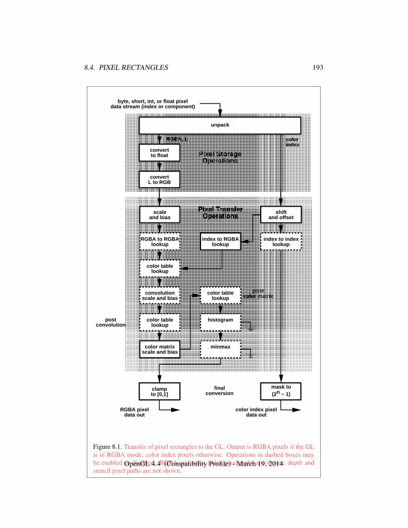
8.4. PIXEL RECTANGLES 193
� � � � � � � � � � � � � � � � � � � � � � � � � � � � � � �� � � � � � � � � � � � � � � � � � � � � � � � � � � � � � �� � � � � � � � � � � � � � � � � � � � � � � � � � � � � � �� � � � � � � � � � � � � � � � � � � � � � � � � � � � � � �� � � � � � � � � � � � � � � � � � � � � � � � � � � � � � �� � � � � � � � � � � � � � � � � � � � � � � � � � � � � � �� � � � � � � � � � � � � � � � � � � � � � � � � � � � � � �� � � � � � � � � � � � � � � � � � � � � � � � � � � � � � �� � � � � � � � � � � � � � � � � � � � � � � � � � � � � � �� � � � � � � � � � � � � � � � � � � � � � � � � � � � � � �� � � � � � � � � � � � � � � � � � � � � � � � � � � � � � �� � � � � � � � � � � � � � � � � � � � � � � � � � � � � � �� � � � � � � � � � � � � � � � � � � � � � � � � � � � � � �
unpack
convertto float
convertL to RGB
RGBA, L
Pixel StorageOperations
byte, short, int, o r float pixeldata stream (index or component)
colorindex
postconvolution
� � � � � � � � � � � � � � � � � � � � � � � � � � � � � � � �� � � � � � � � � � � � � � � � � � � � � � � � � � � � � � � �� � � � � � � � � � � � � � � � � � � � � � � � � � � � � � � �� � � � � � � � � � � � � � � � � � � � � � � � � � � � � � � �� � � � � � � � � � � � � � � � � � � � � � � � � � � � � � � �� � � � � � � � � � � � � � � � � � � � � � � � � � � � � � � �� � � � � � � � � � � � � � � � � � � � � � � � � � � � � � � �� � � � � � � � � � � � � � � � � � � � � � � � � � � � � � � �� � � � � � � � � � � � � � � � � � � � � � � � � � � � � � � �� � � � � � � � � � � � � � � � � � � � � � � � � � � � � � � �� � � � � � � � � � � � � � � � � � � � � � � � � � � � � � � �� � � � � � � � � � � � � � � � � � � � � � � � � � � � � � � �� � � � � � � � � � � � � � � � � � � � � � � � � � � � � � � �� � � � � � � � � � � � � � � � � � � � � � � � � � � � � � � �� � � � � � � � � � � � � � � � � � � � � � � � � � � � � � � �� � � � � � � � � � � � � � � � � � � � � � � � � � � � � � � �� � � � � � � � � � � � � � � � � � � � � � � � � � � � � � � �� � � � � � � � � � � � � � � � � � � � � � � � � � � � � � � �� � � � � � � � � � � � � � � � � � � � � � � � � � � � � � � �� � � � � � � � � � � � � � � � � � � � � � � � � � � � � � � �� � � � � � � � � � � � � � � � � � � � � � � � � � � � � � � �� � � � � � � � � � � � � � � � � � � � � � � � � � � � � � � �� � � � � � � � � � � � � � � � � � � � � � � � � � � � � � � �� � � � � � � � � � � � � � � � � � � � � � � � � � � � � � � �� � � � � � � � � � � � � � � � � � � � � � � � � � � � � � � �� � � � � � � � � � � � � � � � � � � � � � � � � � � � � � � �� � � � � � � � � � � � � � � � � � � � � � � � � � � � � � � �� � � � � � � � � � � � � � � � � � � � � � � � � � � � � � � �� � � � � � � � � � � � � � � � � � � � � � � � � � � � � � � �
scaleand bias
Pixel TransferOperations
color table lookup
convolution scale a nd bias
histogram
minmax
color table lookup
RGBA to RGBA lookup
shiftand offset
index to index look up
index to RGBA looku p
color table lookup
color matrixscale and bias
postcolor matrix
color index pixeldata out
RGBA pixeldata out
clampto [0,1]
mask to(2n − 1)
finalconversion
Figure 8.1. Transfer of pixel rectangles to the GL. Output is RGBA pixels if the GLis in RGBA mode, color index pixels otherwise. Operations in dashed boxes maybe enabled or disabled. RGBA and color index pixel paths are shown; depth andstencil pixel paths are not shown.
OpenGL 4.4 (Compatibility Profile) - March 19, 2014
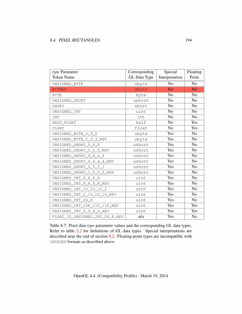
8.4. PIXEL RECTANGLES 194
type Parameter Corresponding Special FloatingToken Name GL Data Type Interpretation PointUNSIGNED_BYTE ubyte No NoBITMAP ubyte Yes NoBYTE byte No NoUNSIGNED_SHORT ushort No NoSHORT short No NoUNSIGNED_INT uint No NoINT int No NoHALF_FLOAT half No YesFLOAT float No YesUNSIGNED_BYTE_3_3_2 ubyte Yes NoUNSIGNED_BYTE_2_3_3_REV ubyte Yes NoUNSIGNED_SHORT_5_6_5 ushort Yes NoUNSIGNED_SHORT_5_6_5_REV ushort Yes NoUNSIGNED_SHORT_4_4_4_4 ushort Yes NoUNSIGNED_SHORT_4_4_4_4_REV ushort Yes NoUNSIGNED_SHORT_5_5_5_1 ushort Yes NoUNSIGNED_SHORT_1_5_5_5_REV ushort Yes NoUNSIGNED_INT_8_8_8_8 uint Yes NoUNSIGNED_INT_8_8_8_8_REV uint Yes NoUNSIGNED_INT_10_10_10_2 uint Yes NoUNSIGNED_INT_2_10_10_10_REV uint Yes NoUNSIGNED_INT_24_8 uint Yes NoUNSIGNED_INT_10F_11F_11F_REV uint Yes YesUNSIGNED_INT_5_9_9_9_REV uint Yes YesFLOAT_32_UNSIGNED_INT_24_8_REV n/a Yes No
Table 8.7: Pixel data type parameter values and the corresponding GL data types.Refer to table 2.2 for definitions of GL data types. Special interpretations aredescribed near the end of section 8.2. Floating-point types are incompatible withINTEGER formats as described above.
OpenGL 4.4 (Compatibility Profile) - March 19, 2014
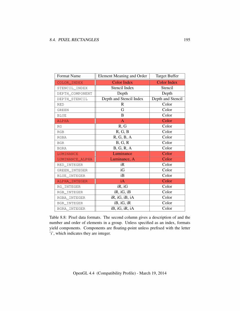
8.4. PIXEL RECTANGLES 195
Format Name Element Meaning and Order Target BufferCOLOR_INDEX Color Index Color IndexSTENCIL_INDEX Stencil Index StencilDEPTH_COMPONENT Depth DepthDEPTH_STENCIL Depth and Stencil Index Depth and StencilRED R ColorGREEN G ColorBLUE B ColorALPHA A ColorRG R, G ColorRGB R, G, B ColorRGBA R, G, B, A ColorBGR B, G, R ColorBGRA B, G, R, A ColorLUMINANCE Luminance ColorLUMINANCE_ALPHA Luminance, A ColorRED_INTEGER iR ColorGREEN_INTEGER iG ColorBLUE_INTEGER iB ColorALPHA_INTEGER iA ColorRG_INTEGER iR, iG ColorRGB_INTEGER iR, iG, iB ColorRGBA_INTEGER iR, iG, iB, iA ColorBGR_INTEGER iB, iG, iR ColorBGRA_INTEGER iB, iG, iR, iA Color
Table 8.8: Pixel data formats. The second column gives a description of and thenumber and order of elements in a group. Unless specified as an index, formatsyield components. Components are floating-point unless prefixed with the letter’i’, which indicates they are integer.
OpenGL 4.4 (Compatibility Profile) - March 19, 2014
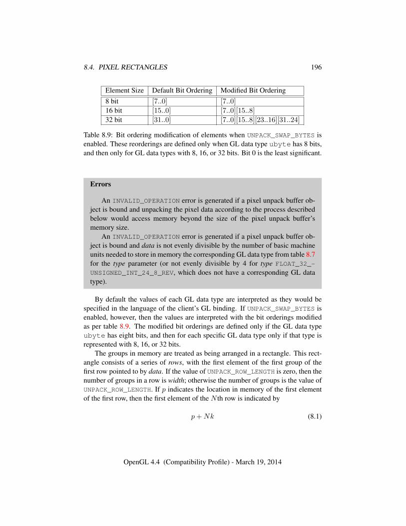
8.4. PIXEL RECTANGLES 196
Element Size Default Bit Ordering Modified Bit Ordering8 bit [7..0] [7..0]
16 bit [15..0] [7..0][15..8]
32 bit [31..0] [7..0][15..8][23..16][31..24]
Table 8.9: Bit ordering modification of elements when UNPACK_SWAP_BYTES isenabled. These reorderings are defined only when GL data type ubyte has 8 bits,and then only for GL data types with 8, 16, or 32 bits. Bit 0 is the least significant.
Errors
An INVALID_OPERATION error is generated if a pixel unpack buffer ob-ject is bound and unpacking the pixel data according to the process describedbelow would access memory beyond the size of the pixel unpack buffer’smemory size.
An INVALID_OPERATION error is generated if a pixel unpack buffer ob-ject is bound and data is not evenly divisible by the number of basic machineunits needed to store in memory the corresponding GL data type from table 8.7for the type parameter (or not evenly divisible by 4 for type FLOAT_32_-
UNSIGNED_INT_24_8_REV, which does not have a corresponding GL datatype).
By default the values of each GL data type are interpreted as they would bespecified in the language of the client’s GL binding. If UNPACK_SWAP_BYTES isenabled, however, then the values are interpreted with the bit orderings modifiedas per table 8.9. The modified bit orderings are defined only if the GL data typeubyte has eight bits, and then for each specific GL data type only if that type isrepresented with 8, 16, or 32 bits.
The groups in memory are treated as being arranged in a rectangle. This rect-angle consists of a series of rows, with the first element of the first group of thefirst row pointed to by data. If the value of UNPACK_ROW_LENGTH is zero, then thenumber of groups in a row is width; otherwise the number of groups is the value ofUNPACK_ROW_LENGTH. If p indicates the location in memory of the first elementof the first row, then the first element of the N th row is indicated by
p+Nk (8.1)
OpenGL 4.4 (Compatibility Profile) - March 19, 2014

8.4. PIXEL RECTANGLES 197
� � � � � � � � � �� � � � � � � � � �� � � � � � � � � �� � � � � � � � � �� � � � � � � � � �� � � � � � � � � �� � � � � � � � � �� � � � � � � � � �
SKIP_ROWS
SKIP_PIXELS
ROW_LENGTH
subimage
Figure 8.2. Selecting a subimage from an image. The indicated parameter namesare prefixed by UNPACK_ for DrawPixels and by PACK_ for ReadPixels.
where N is the row number (counting from zero) and k is defined as
k =
{nl s ≥ a,as
⌈snla
⌉s < a
(8.2)
where n is the number of elements in a group, l is the number of groups in the row,a is the value of UNPACK_ALIGNMENT, and s is the size, in units of GL ubytes, ofan element. If the number of bits per element is not 1, 2, 4, or 8 times the numberof bits in a GL ubyte, then k = nl for all values of a.
There is a mechanism for selecting a sub-rectangle of groups from alarger containing rectangle. This mechanism relies on three integer parameters:UNPACK_ROW_LENGTH, UNPACK_SKIP_ROWS, and UNPACK_SKIP_PIXELS. Be-fore obtaining the first group from memory, the data pointer is advanced by(UNPACK_SKIP_PIXELS)n + (UNPACK_SKIP_ROWS)k elements. Then widthgroups are obtained from contiguous elements in memory (without advancing thepointer), after which the pointer is advanced by k elements. height sets of widthgroups of values are obtained this way. See figure 8.2.
Special InterpretationsA type matching one of the types in table 8.10 is a special case in which all the
components of each group are packed into a single unsigned byte, unsigned short,or unsigned int, depending on the type. If type is FLOAT_32_UNSIGNED_INT_-24_8_REV, the components of each group are contained within two 32-bit words;
OpenGL 4.4 (Compatibility Profile) - March 19, 2014
8.4. PIXEL RECTANGLES 198
the first word contains the float component, and the second word contains a packed24-bit unused field, followed by an 8-bit component. The number of componentsper packed pixel is fixed by the type, and must match the number of componentsper group indicated by the format parameter, as listed in table 8.10.
An INVALID_OPERATION error is generated by any command processingpixel rectangles if a mismatch occurs.
Bitfield locations of the first, second, third, and fourth components of eachpacked pixel type are illustrated in tables 8.11- 8.14. Each bitfield is interpreted asan unsigned integer value.
Components are normally packed with the first component in the most signif-icant bits of the bitfield, and successive component occupying progressively lesssignificant locations. Types whose token names end with _REV reverse the compo-nent packing order from least to most significant locations. In all cases, the mostsignificant bit of each component is packed in the most significant bit location ofits location in the bitfield.
OpenGL 4.4 (Compatibility Profile) - March 19, 2014
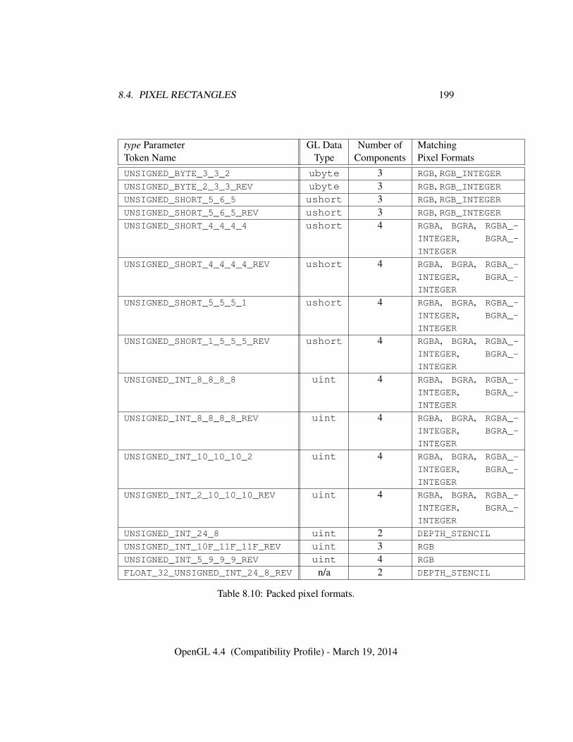
8.4. PIXEL RECTANGLES 199
type Parameter GL Data Number of MatchingToken Name Type Components Pixel FormatsUNSIGNED_BYTE_3_3_2 ubyte 3 RGB, RGB_INTEGERUNSIGNED_BYTE_2_3_3_REV ubyte 3 RGB, RGB_INTEGERUNSIGNED_SHORT_5_6_5 ushort 3 RGB, RGB_INTEGERUNSIGNED_SHORT_5_6_5_REV ushort 3 RGB, RGB_INTEGERUNSIGNED_SHORT_4_4_4_4 ushort 4 RGBA, BGRA, RGBA_-
INTEGER, BGRA_-
INTEGER
UNSIGNED_SHORT_4_4_4_4_REV ushort 4 RGBA, BGRA, RGBA_-
INTEGER, BGRA_-
INTEGER
UNSIGNED_SHORT_5_5_5_1 ushort 4 RGBA, BGRA, RGBA_-
INTEGER, BGRA_-
INTEGER
UNSIGNED_SHORT_1_5_5_5_REV ushort 4 RGBA, BGRA, RGBA_-
INTEGER, BGRA_-
INTEGER
UNSIGNED_INT_8_8_8_8 uint 4 RGBA, BGRA, RGBA_-
INTEGER, BGRA_-
INTEGER
UNSIGNED_INT_8_8_8_8_REV uint 4 RGBA, BGRA, RGBA_-
INTEGER, BGRA_-
INTEGER
UNSIGNED_INT_10_10_10_2 uint 4 RGBA, BGRA, RGBA_-
INTEGER, BGRA_-
INTEGER
UNSIGNED_INT_2_10_10_10_REV uint 4 RGBA, BGRA, RGBA_-
INTEGER, BGRA_-
INTEGER
UNSIGNED_INT_24_8 uint 2 DEPTH_STENCIL
UNSIGNED_INT_10F_11F_11F_REV uint 3 RGB
UNSIGNED_INT_5_9_9_9_REV uint 4 RGB
FLOAT_32_UNSIGNED_INT_24_8_REV n/a 2 DEPTH_STENCIL
Table 8.10: Packed pixel formats.
OpenGL 4.4 (Compatibility Profile) - March 19, 2014
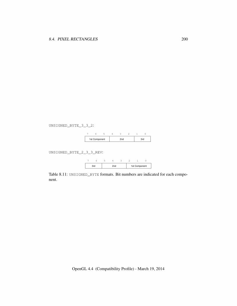
8.4. PIXEL RECTANGLES 200
UNSIGNED_BYTE_3_3_2:
7 6 5 4 3 2 1 0
1st Component 2nd 3rd
UNSIGNED_BYTE_2_3_3_REV:
7 6 5 4 3 2 1 0
3rd 2nd 1st Component
Table 8.11: UNSIGNED_BYTE formats. Bit numbers are indicated for each compo-nent.
OpenGL 4.4 (Compatibility Profile) - March 19, 2014
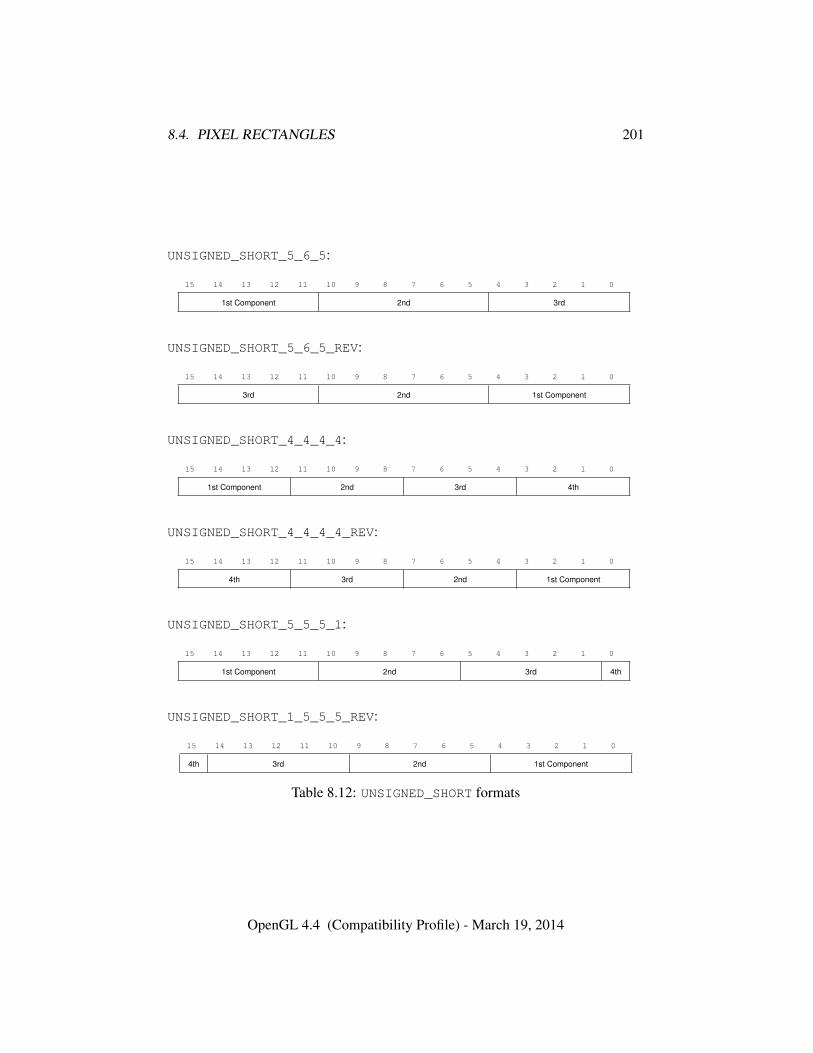
8.4. PIXEL RECTANGLES 201
UNSIGNED_SHORT_5_6_5:
15 14 13 12 11 10 9 8 7 6 5 4 3 2 1 0
1st Component 2nd 3rd
UNSIGNED_SHORT_5_6_5_REV:
15 14 13 12 11 10 9 8 7 6 5 4 3 2 1 0
3rd 2nd 1st Component
UNSIGNED_SHORT_4_4_4_4:
15 14 13 12 11 10 9 8 7 6 5 4 3 2 1 0
1st Component 2nd 3rd 4th
UNSIGNED_SHORT_4_4_4_4_REV:
15 14 13 12 11 10 9 8 7 6 5 4 3 2 1 0
4th 3rd 2nd 1st Component
UNSIGNED_SHORT_5_5_5_1:
15 14 13 12 11 10 9 8 7 6 5 4 3 2 1 0
1st Component 2nd 3rd 4th
UNSIGNED_SHORT_1_5_5_5_REV:
15 14 13 12 11 10 9 8 7 6 5 4 3 2 1 0
4th 3rd 2nd 1st Component
Table 8.12: UNSIGNED_SHORT formats
OpenGL 4.4 (Compatibility Profile) - March 19, 2014
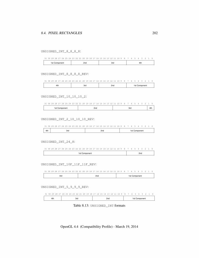
8.4. PIXEL RECTANGLES 202
UNSIGNED_INT_8_8_8_8:
31 30 29 28 27 26 25 24 23 22 21 20 19 18 17 16 15 14 13 12 11 10 9 8 7 6 5 4 3 2 1 0
1st Component 2nd 3rd 4th
UNSIGNED_INT_8_8_8_8_REV:
31 30 29 28 27 26 25 24 23 22 21 20 19 18 17 16 15 14 13 12 11 10 9 8 7 6 5 4 3 2 1 0
4th 3rd 2nd 1st Component
UNSIGNED_INT_10_10_10_2:
31 30 29 28 27 26 25 24 23 22 21 20 19 18 17 16 15 14 13 12 11 10 9 8 7 6 5 4 3 2 1 0
1st Component 2nd 3rd 4th
UNSIGNED_INT_2_10_10_10_REV:
31 30 29 28 27 26 25 24 23 22 21 20 19 18 17 16 15 14 13 12 11 10 9 8 7 6 5 4 3 2 1 0
4th 3rd 2nd 1st Component
UNSIGNED_INT_24_8:
31 30 29 28 27 26 25 24 23 22 21 20 19 18 17 16 15 14 13 12 11 10 9 8 7 6 5 4 3 2 1 0
1st Component 2nd
UNSIGNED_INT_10F_11F_11F_REV:
31 30 29 28 27 26 25 24 23 22 21 20 19 18 17 16 15 14 13 12 11 10 9 8 7 6 5 4 3 2 1 0
3rd 2nd 1st Component
UNSIGNED_INT_5_9_9_9_REV:
31 30 29 28 27 26 25 24 23 22 21 20 19 18 17 16 15 14 13 12 11 10 9 8 7 6 5 4 3 2 1 0
4th 3rd 2nd 1st Component
Table 8.13: UNSIGNED_INT formats
OpenGL 4.4 (Compatibility Profile) - March 19, 2014
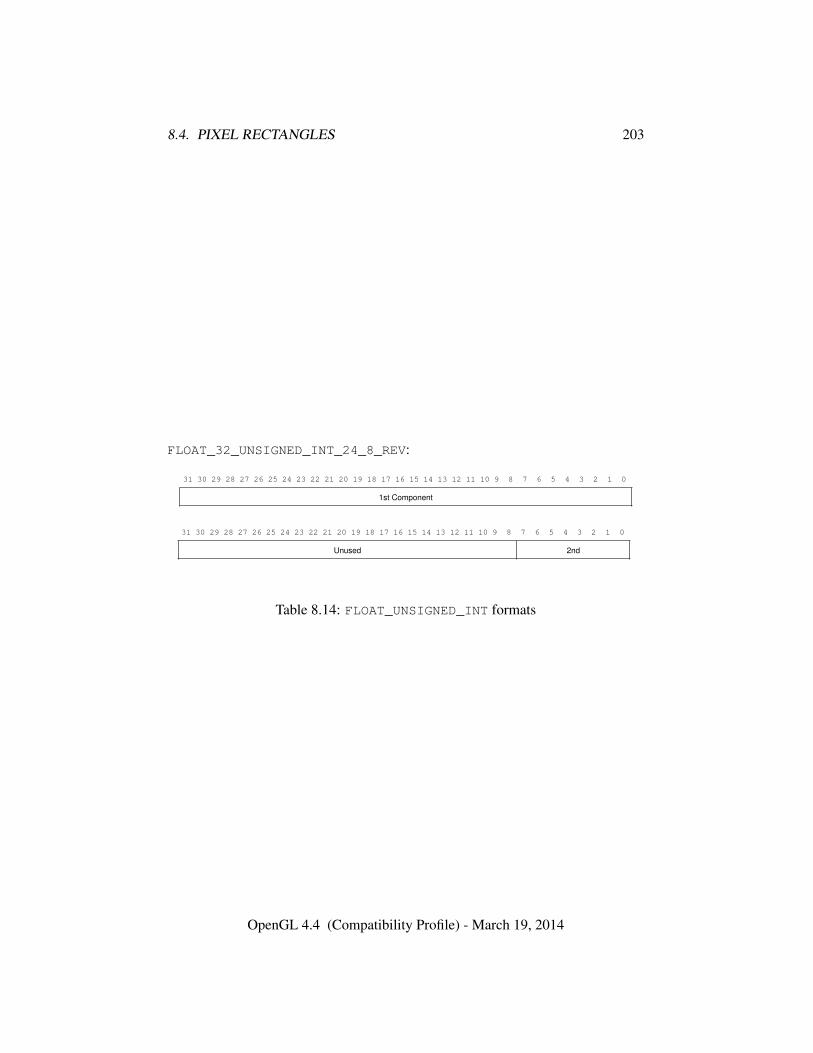
8.4. PIXEL RECTANGLES 203
FLOAT_32_UNSIGNED_INT_24_8_REV:
31 30 29 28 27 26 25 24 23 22 21 20 19 18 17 16 15 14 13 12 11 10 9 8 7 6 5 4 3 2 1 0
1st Component
31 30 29 28 27 26 25 24 23 22 21 20 19 18 17 16 15 14 13 12 11 10 9 8 7 6 5 4 3 2 1 0
Unused 2nd
Table 8.14: FLOAT_UNSIGNED_INT formats
OpenGL 4.4 (Compatibility Profile) - March 19, 2014
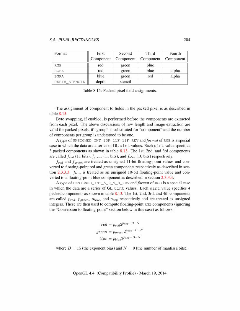
8.4. PIXEL RECTANGLES 204
Format First Second Third FourthComponent Component Component Component
RGB red green blueRGBA red green blue alphaBGRA blue green red alphaDEPTH_STENCIL depth stencil
Table 8.15: Packed pixel field assignments.
The assignment of component to fields in the packed pixel is as described intable 8.15.
Byte swapping, if enabled, is performed before the components are extractedfrom each pixel. The above discussions of row length and image extraction arevalid for packed pixels, if “group” is substituted for “component” and the numberof components per group is understood to be one.
A type of UNSIGNED_INT_10F_11F_11F_REV and format of RGB is a specialcase in which the data are a series of GL uint values. Each uint value specifies3 packed components as shown in table 8.13. The 1st, 2nd, and 3rd componentsare called fred (11 bits), fgreen (11 bits), and fblue (10 bits) respectively.
fred and fgreen are treated as unsigned 11-bit floating-point values and con-verted to floating-point red and green components respectively as described in sec-tion 2.3.3.3. fblue is treated as an unsigned 10-bit floating-point value and con-verted to a floating-point blue component as described in section 2.3.3.4.
A type of UNSIGNED_INT_5_9_9_9_REV and format of RGB is a special casein which the data are a series of GL uint values. Each uint value specifies 4packed components as shown in table 8.13. The 1st, 2nd, 3rd, and 4th componentsare called pred, pgreen, pblue, and pexp respectively and are treated as unsignedintegers. These are then used to compute floating-point RGB components (ignoringthe “Conversion to floating-point” section below in this case) as follows:
red = pred2pexp−B−N
green = pgreen2pexp−B−N
blue = pblue2pexp−B−N
where B = 15 (the exponent bias) and N = 9 (the number of mantissa bits).
OpenGL 4.4 (Compatibility Profile) - March 19, 2014
8.4. PIXEL RECTANGLES 205
8.4.4.2 Conversion to floating-point
This step applies only to groups of floating-point components. It is not performedon indices or integer components. For groups containing both components andindices, such as DEPTH_STENCIL, the indices are not converted.
Each element in a group is converted to a floating-point value. For unsignedor signed normalized fixed-point elements, equations 2.1 or 2.2, respectively, areused.
8.4.4.3 Conversion to RGB
This step is applied only if the format is LUMINANCE or LUMINANCE_ALPHA. Ifthe format is LUMINANCE, then each group of one element is converted to a groupof R, G, and B (three) elements by copying the original single element into each ofthe three new elements. If the format is LUMINANCE_ALPHA, then each group oftwo elements is converted to a group of R, G, B, and A (four) elements by copyingthe first original element into each of the first three new elements and copying thesecond original element to the A (fourth) new element.
8.4.4.4 Final Expansion to RGBA
This step is performed only for non-depth component groups. Each group is con-verted to a group of 4 elements as follows: if a group does not contain an A element,then A is added and set to one for integer components or 1.0 for floating-point com-ponents. If any of R, G, or B is missing from the group, each missing element isadded and assigned a value of 0 for integer components or 0.0 for floating-pointcomponents.
8.4.4.5 Pixel Transfer Operations
This step is actually a sequence of steps. Because the pixel transfer operationsare performed equivalently during the drawing, copying, and reading of pixels (seechapter 18), and during the specification of texture images (either from memoryor from the framebuffer), they are described separately in section 8.4.5. Afterthe operations described in that section are completed, groups are processed asdescribed in the following sections.
8.4.5 Pixel Transfer Operations
The GL defines six kinds of pixel groups:
OpenGL 4.4 (Compatibility Profile) - March 19, 2014
8.4. PIXEL RECTANGLES 206
1. Floating-point RGBA component: Each group comprises four color compo-nents in floating-point format: red, green, blue, and alpha.
2. Integer RGBA component: Each group comprises four color components ininteger format: red, green, blue, and alpha.
3. Depth component: Each group comprises a single depth component.
4. Color index: Each group comprises a single color index.
5. Stencil index: Each group comprises a single stencil index.
6. Depth/stencil: Each group comprises a single depth component and a singlestencil index.
Each operation described in this section is applied sequentially to each pixelgroup in an image. Many operations are applied only to pixel groups of certainkinds; if an operation is not applicable to a given group, it is skipped. None of theoperations defined in this section affect integer RGBA component pixel groups.
This step applies only to RGBA component and depth component groups, andto the depth components in depth/stencil groups. Each component is multipliedby an appropriate signed scale factor: RED_SCALE for an R component, GREEN_-SCALE for a G component, BLUE_SCALE for a B component, and ALPHA_SCALE
for an A component, or DEPTH_SCALE for a depth component. Then the resultis added to the appropriate signed bias: RED_BIAS, GREEN_BIAS, BLUE_BIAS,ALPHA_BIAS, or DEPTH_BIAS.
8.4.5.1 Arithmetic on Indices
This step applies only to color index and stencil index groups, and to the stencilindices in depth/stencil groups. If the index is a floating-point value, it is convertedto fixed-point, with an unspecified number of bits to the right of the binary pointand at least dlog2(MAX_PIXEL_MAP_TABLE)e bits to the left of the binary point.Indices that are already integers remain so; any fraction bits in the resulting fixed-point value are zero.
The fixed-point index is then shifted by |INDEX_SHIFT| bits, left ifINDEX_SHIFT > 0 and right otherwise. In either case the shift is zero-filled.Then, the signed integer offset INDEX_OFFSET is added to the index.
OpenGL 4.4 (Compatibility Profile) - March 19, 2014
8.4. PIXEL RECTANGLES 207
8.4.5.2 RGBA to RGBA Lookup
This step applies only to RGBA component groups, and is skipped if MAP_COLORis FALSE. First, each component is clamped to the range [0, 1]. There is a ta-ble associated with each of the R, G, B, and A component elements: PIXEL_-
MAP_R_TO_R for R, PIXEL_MAP_G_TO_G for G, PIXEL_MAP_B_TO_B for B, andPIXEL_MAP_A_TO_A for A. Each element is multiplied by an integer one less thanthe size of the corresponding table, and, for each element, an address is found byrounding this value to the nearest integer. For each element, the addressed value inthe corresponding table replaces the element.
8.4.5.3 Color Index Lookup
This step applies only to color index groups. If the GL command that invokes thepixel transfer operation requires that RGBA component pixel groups be generated,then a conversion is performed at this step. RGBA component pixel groups arerequired if
• The groups will be rasterized, and the GL is in RGBA mode, or
• The groups will be loaded as an image into texture memory, or
• The groups will be returned to client memory with a format other thanCOLOR_INDEX.
If RGBA component groups are required, then the integer part of the index isused to reference 4 tables of color components: PIXEL_MAP_I_TO_R, PIXEL_-MAP_I_TO_G, PIXEL_MAP_I_TO_B, and PIXEL_MAP_I_TO_A. Each of these ta-bles must have 2n entries for some integer value of n (n may be different for eachtable). For each table, the index is first rounded to the nearest integer; the resultis ANDed with 2n − 1, and the resulting value used as an address into the table.The indexed value becomes an R, G, B, or A value, as appropriate. The group offour elements so obtained replaces the index, changing the group’s type to RGBAcomponent.
If RGBA component groups are not required, and if MAP_COLOR is enabled,then the index is looked up in the PIXEL_MAP_I_TO_I table (otherwise, the indexis not looked up). Again, the table must have 2n entries for some integer n. Theindex is first rounded to the nearest integer; the result is ANDed with 2n − 1, andthe resulting value used as an address into the table. The value in the table replacesthe index. The floating-point table value is first rounded to a fixed-point value withunspecified precision. The group’s type remains color index.
OpenGL 4.4 (Compatibility Profile) - March 19, 2014
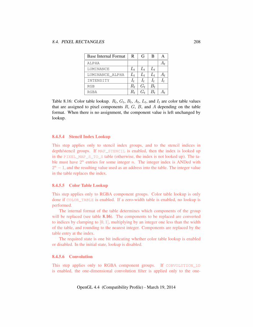
8.4. PIXEL RECTANGLES 208
Base Internal Format R G B AALPHA At
LUMINANCE Lt Lt Lt
LUMINANCE_ALPHA Lt Lt Lt At
INTENSITY It It It ItRGB Rt Gt Bt
RGBA Rt Gt Bt At
Table 8.16: Color table lookup. Rt, Gt, Bt, At, Lt, and It are color table valuesthat are assigned to pixel components R, G, B, and A depending on the tableformat. When there is no assignment, the component value is left unchanged bylookup.
8.4.5.4 Stencil Index Lookup
This step applies only to stencil index groups, and to the stencil indices indepth/stencil groups. If MAP_STENCIL is enabled, then the index is looked upin the PIXEL_MAP_S_TO_S table (otherwise, the index is not looked up). The ta-ble must have 2n entries for some integer n. The integer index is ANDed with2n − 1, and the resulting value used as an address into the table. The integer valuein the table replaces the index.
8.4.5.5 Color Table Lookup
This step applies only to RGBA component groups. Color table lookup is onlydone if COLOR_TABLE is enabled. If a zero-width table is enabled, no lookup isperformed.
The internal format of the table determines which components of the groupwill be replaced (see table 8.16). The components to be replaced are convertedto indices by clamping to [0, 1], multiplying by an integer one less than the widthof the table, and rounding to the nearest integer. Components are replaced by thetable entry at the index.
The required state is one bit indicating whether color table lookup is enabledor disabled. In the initial state, lookup is disabled.
8.4.5.6 Convolution
This step applies only to RGBA component groups. If CONVOLUTION_1D
is enabled, the one-dimensional convolution filter is applied only to the one-
OpenGL 4.4 (Compatibility Profile) - March 19, 2014
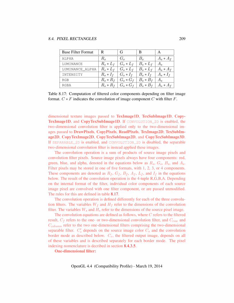
8.4. PIXEL RECTANGLES 209
Base Filter Format R G B AALPHA Rs Gs Bs As ∗Af
LUMINANCE Rs ∗ Lf Gs ∗ Lf Bs ∗ Lf As
LUMINANCE_ALPHA Rs ∗ Lf Gs ∗ Lf Bs ∗ Lf As ∗Af
INTENSITY Rs ∗ If Gs ∗ If Bs ∗ If As ∗ IfRGB Rs ∗Rf Gs ∗Gf Bs ∗Bf As
RGBA Rs ∗Rf Gs ∗Gf Bs ∗Bf As ∗Af
Table 8.17: Computation of filtered color components depending on filter imageformat. C ∗ F indicates the convolution of image component C with filter F .
dimensional texture images passed to TexImage1D, TexSubImage1D, Copy-TexImage1D, and CopyTexSubImage1D. If CONVOLUTION_2D is enabled, thetwo-dimensional convolution filter is applied only to the two-dimensional im-ages passed to DrawPixels, CopyPixels, ReadPixels, TexImage2D, TexSubIm-age2D, CopyTexImage2D, CopyTexSubImage2D, and CopyTexSubImage3D.If SEPARABLE_2D is enabled, and CONVOLUTION_2D is disabled, the separabletwo-dimensional convolution filter is instead applied these images.
The convolution operation is a sum of products of source image pixels andconvolution filter pixels. Source image pixels always have four components: red,green, blue, and alpha, denoted in the equations below as Rs, Gs, Bs, and As.Filter pixels may be stored in one of five formats, with 1, 2, 3, or 4 components.These components are denoted as Rf , Gf , Bf , Af , Lf , and If in the equationsbelow. The result of the convolution operation is the 4-tuple R,G,B,A. Dependingon the internal format of the filter, individual color components of each sourceimage pixel are convolved with one filter component, or are passed unmodified.The rules for this are defined in table 8.17.
The convolution operation is defined differently for each of the three convolu-tion filters. The variables Wf and Hf refer to the dimensions of the convolutionfilter. The variables Ws and Hs refer to the dimensions of the source pixel image.
The convolution equations are defined as follows, where C refers to the filteredresult, Cf refers to the one- or two-dimensional convolution filter, and Crow andCcolumn refer to the two one-dimensional filters comprising the two-dimensionalseparable filter. C ′s depends on the source image color Cs and the convolutionborder mode as described below. Cr, the filtered output image, depends on allof these variables and is described separately for each border mode. The pixelindexing nomenclature is decribed in section 8.4.3.5.
One-dimensional filter:
OpenGL 4.4 (Compatibility Profile) - March 19, 2014
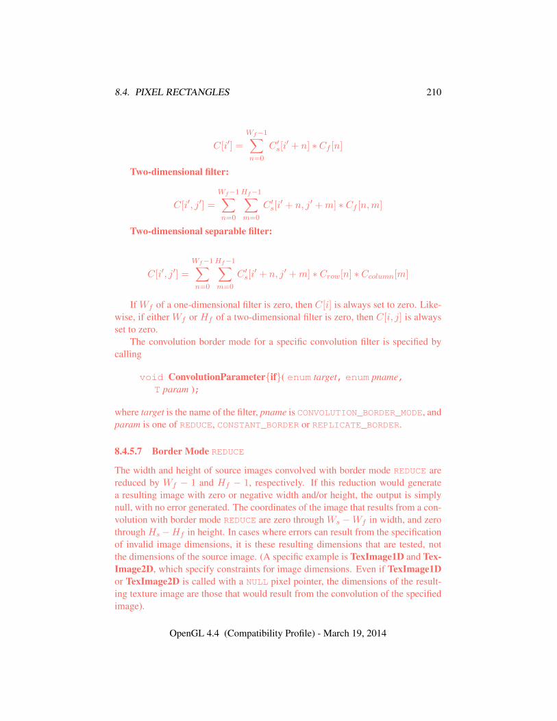
8.4. PIXEL RECTANGLES 210
C[i′] =
Wf−1∑n=0
C ′s[i′ + n] ∗ Cf [n]
Two-dimensional filter:
C[i′, j′] =
Wf−1∑n=0
Hf−1∑m=0
C ′s[i′ + n, j′ +m] ∗ Cf [n,m]
Two-dimensional separable filter:
C[i′, j′] =
Wf−1∑n=0
Hf−1∑m=0
C ′s[i′ + n, j′ +m] ∗ Crow[n] ∗ Ccolumn[m]
If Wf of a one-dimensional filter is zero, then C[i] is always set to zero. Like-wise, if either Wf or Hf of a two-dimensional filter is zero, then C[i, j] is alwaysset to zero.
The convolution border mode for a specific convolution filter is specified bycalling
void ConvolutionParameter{if}( enum target, enum pname,T param );
where target is the name of the filter, pname is CONVOLUTION_BORDER_MODE, andparam is one of REDUCE, CONSTANT_BORDER or REPLICATE_BORDER.
8.4.5.7 Border Mode REDUCE
The width and height of source images convolved with border mode REDUCE arereduced by Wf − 1 and Hf − 1, respectively. If this reduction would generatea resulting image with zero or negative width and/or height, the output is simplynull, with no error generated. The coordinates of the image that results from a con-volution with border mode REDUCE are zero through Ws −Wf in width, and zerothrough Hs −Hf in height. In cases where errors can result from the specificationof invalid image dimensions, it is these resulting dimensions that are tested, notthe dimensions of the source image. (A specific example is TexImage1D and Tex-Image2D, which specify constraints for image dimensions. Even if TexImage1Dor TexImage2D is called with a NULL pixel pointer, the dimensions of the result-ing texture image are those that would result from the convolution of the specifiedimage).
OpenGL 4.4 (Compatibility Profile) - March 19, 2014
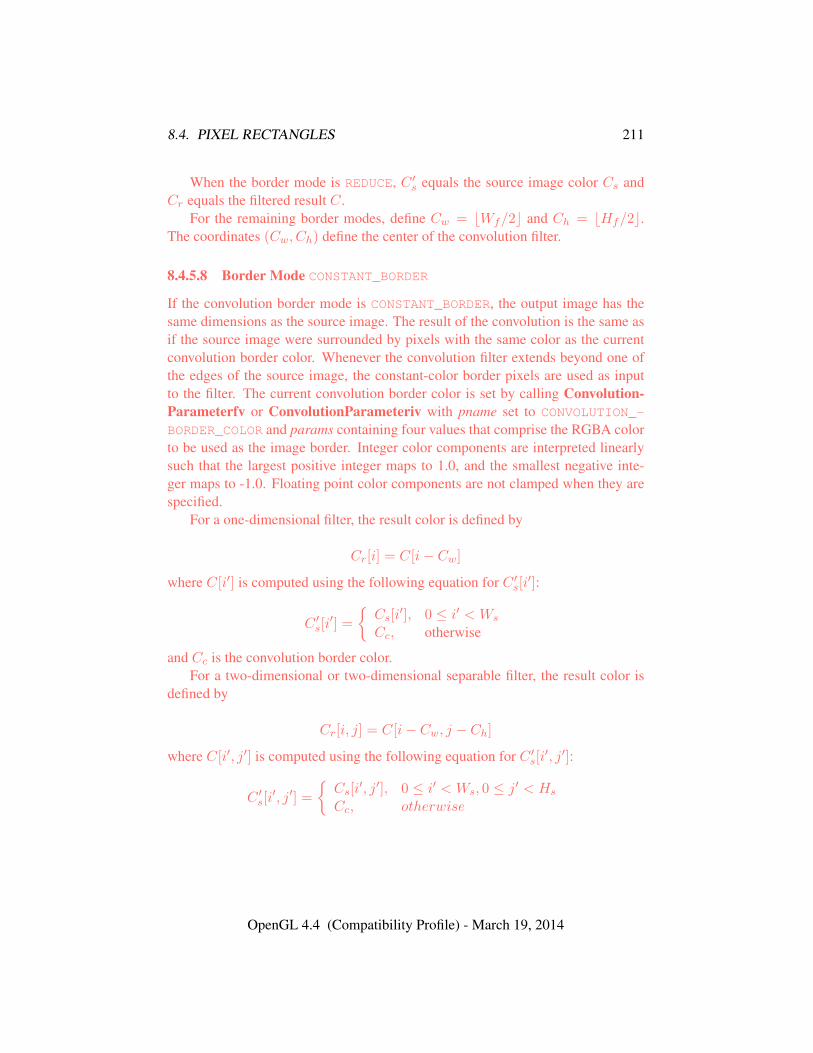
8.4. PIXEL RECTANGLES 211
When the border mode is REDUCE, C ′s equals the source image color Cs andCr equals the filtered result C.
For the remaining border modes, define Cw = bWf/2c and Ch = bHf/2c.The coordinates (Cw, Ch) define the center of the convolution filter.
8.4.5.8 Border Mode CONSTANT_BORDER
If the convolution border mode is CONSTANT_BORDER, the output image has thesame dimensions as the source image. The result of the convolution is the same asif the source image were surrounded by pixels with the same color as the currentconvolution border color. Whenever the convolution filter extends beyond one ofthe edges of the source image, the constant-color border pixels are used as inputto the filter. The current convolution border color is set by calling Convolution-Parameterfv or ConvolutionParameteriv with pname set to CONVOLUTION_-
BORDER_COLOR and params containing four values that comprise the RGBA colorto be used as the image border. Integer color components are interpreted linearlysuch that the largest positive integer maps to 1.0, and the smallest negative inte-ger maps to -1.0. Floating point color components are not clamped when they arespecified.
For a one-dimensional filter, the result color is defined by
Cr[i] = C[i− Cw]
where C[i′] is computed using the following equation for C ′s[i′]:
C ′s[i′] =
{Cs[i
′], 0 ≤ i′ < Ws
Cc, otherwise
and Cc is the convolution border color.For a two-dimensional or two-dimensional separable filter, the result color is
defined by
Cr[i, j] = C[i− Cw, j − Ch]
where C[i′, j′] is computed using the following equation for C ′s[i′, j′]:
C ′s[i′, j′] =
{Cs[i
′, j′], 0 ≤ i′ < Ws, 0 ≤ j′ < Hs
Cc, otherwise
OpenGL 4.4 (Compatibility Profile) - March 19, 2014
8.4. PIXEL RECTANGLES 212
8.4.5.9 Border Mode REPLICATE_BORDER
The convolution border mode REPLICATE_BORDER also produces an output im-age with the same dimensions as the source image. The behavior of this mode isidentical to that of the CONSTANT_BORDER mode except for the treatment of pixellocations where the convolution filter extends beyond the edge of the source im-age. For these locations, it is as if the outermost one-pixel border of the sourceimage was replicated. Conceptually, each pixel in the leftmost one-pixel columnof the source image is replicated Cw times to provide additional image data alongthe left edge, each pixel in the rightmost one-pixel column is replicated Cw timesto provide additional image data along the right edge, and each pixel value in thetop and bottom one-pixel rows is replicated to create Ch rows of image data alongthe top and bottom edges. The pixel value at each corner is also replicated in orderto provide data for the convolution operation at each corner of the source image.
For a one-dimensional filter, the result color is defined by
Cr[i] = C[i− Cw]
where C[i′] is computed using the following equation for C ′s[i′]:
C ′s[i′] = Cs[clamp(i′,Ws)]
and the clamping function clamp(val,max) is defined as
clamp(val,max) =
0, val < 0val, 0 ≤ val < maxmax− 1, val ≥ max
For a two-dimensional or two-dimensional separable filter, the result color isdefined by
Cr[i, j] = C[i− Cw, j − Ch]
where C[i′, j′] is computed using the following equation for C ′s[i′, j′]:
C ′s[i′, j′] = Cs[clamp(i′,Ws), clamp(j′, Hs)]
If a convolution operation is performed, each component of the resulting imageis scaled by the corresponding PixelTransfer parameters: POST_CONVOLUTION_-RED_SCALE for an R component, POST_CONVOLUTION_GREEN_SCALE for a Gcomponent, POST_CONVOLUTION_BLUE_SCALE for a B component, and POST_-CONVOLUTION_ALPHA_SCALE for an A component. The result is added to the
OpenGL 4.4 (Compatibility Profile) - March 19, 2014
8.4. PIXEL RECTANGLES 213
corresponding bias: POST_CONVOLUTION_RED_BIAS, POST_CONVOLUTION_-GREEN_BIAS, POST_CONVOLUTION_BLUE_BIAS, or POST_CONVOLUTION_-
ALPHA_BIAS.The required state is three bits indicating whether each of one-dimensional,
two-dimensional, or separable two-dimensional convolution is enabled or disabled,an integer describing the current convolution border mode, and four floating-pointvalues specifying the convolution border color. In the initial state, all convolu-tion operations are disabled, the border mode is REDUCE, and the border color is(0, 0, 0, 0).
8.4.5.10 Post Convolution Color Table Lookup
This step applies only to RGBA component groups. Post convolution color tablelookup is enabled or disabled by calling Enable or Disable with target POST_-CONVOLUTION_COLOR_TABLE. The post convolution table is defined by callingColorTable with a target argument of POST_CONVOLUTION_COLOR_TABLE. Inall other respects, operation is identical to color table lookup, as defined earlier insection 8.4.5.5.
The required state is one bit indicating whether post convolution table lookupis enabled or disabled. In the initial state, lookup is disabled.
8.4.5.11 Color Matrix Transformation
This step applies only to RGBA component groups. The components aretransformed by the color matrix. Each transformed component is multi-plied by an appropriate signed scale factor: POST_COLOR_MATRIX_RED_SCALEfor an R component, POST_COLOR_MATRIX_GREEN_SCALE for a G compo-nent, POST_COLOR_MATRIX_BLUE_SCALE for a B component, and POST_-
COLOR_MATRIX_ALPHA_SCALE for an A component. The result is addedto a signed bias: POST_COLOR_MATRIX_RED_BIAS, POST_COLOR_MATRIX_-GREEN_BIAS, POST_COLOR_MATRIX_BLUE_BIAS, or POST_COLOR_MATRIX_-ALPHA_BIAS. The resulting components replace each component of the originalgroup.
That is, if Mc is the color matrix, a subscript of s represents the scale term fora component, and a subscript of b represents the bias term, then the components
RGBA
OpenGL 4.4 (Compatibility Profile) - March 19, 2014
8.4. PIXEL RECTANGLES 214
are transformed toR′
G′
B′
A′
=
Rs 0 0 00 Gs 0 00 0 Bs 00 0 0 As
Mc
RGBA
+
Rb
Gb
Bb
Ab
.
8.4.5.12 Post Color Matrix Color Table Lookup
This step applies only to RGBA component groups. Post color matrix color tablelookup is enabled or disabled by calling Enable or Disable with target POST_-COLOR_MATRIX_COLOR_TABLE. The post color matrix table is defined by callingColorTable with a target argument of POST_COLOR_MATRIX_COLOR_TABLE. Inall other respects, operation is identical to color table lookup, as defined in sec-tion 8.4.5.5.
The required state is one bit indicating whether post color matrix lookup isenabled or disabled. In the initial state, lookup is disabled.
8.4.5.13 Histogram
This step applies only to RGBA component groups. Histogram operation is en-abled or disabled by calling Enable or Disable with target HISTOGRAM.
If the width of the table is non-zero, then indices Ri, Gi, Bi, and Ai are de-rived from the red, green, blue, and alpha components of each pixel group (withoutmodifying these components) by clamping each component to [0, 1], multiplyingby one less than the width of the histogram table, and rounding to the nearest in-teger. If the format of the HISTOGRAM table includes red or luminance, the red orluminance component of histogram entry Ri is incremented by one. If the formatof the HISTOGRAM table includes green, the green component of histogram entryGi is incremented by one. The blue and alpha components of histogram entriesBi and Ai are incremented in the same way. If a histogram entry component isincremented beyond its maximum value, its value becomes undefined; this is notan error.
If the Histogram sink parameter is FALSE, histogram operation has no effecton the stream of pixel groups being processed. Otherwise, all RGBA pixel groupsare discarded immediately after the histogram operation is completed. Becausehistogram precedes minmax, no minmax operation is performed. No pixel frag-ments are generated, no change is made to texture memory contents, and no pixelvalues are returned. However, texture object state is modified whether or not pixelgroups are discarded.
OpenGL 4.4 (Compatibility Profile) - March 19, 2014
8.5. TEXTURE IMAGE SPECIFICATION 215
8.4.5.14 Minmax
This step applies only to RGBA component groups. Minmax operation is enabledor disabled by calling Enable or Disable with target MINMAX.
If the format of the minmax table includes red or luminance, the red compo-nent value replaces the red or luminance value in the minimum table element ifand only if it is less than that component. Likewise, if the format includes red orluminance and the red component of the group is greater than the red or luminancevalue in the maximum element, the red group component replaces the red or lumi-nance maximum component. If the format of the table includes green, the greengroup component conditionally replaces the green minimum and/or maximum ifit is smaller or larger, respectively. The blue and alpha group components aresimilarly tested and replaced, if the table format includes blue and/or alpha. Theinternal type of the minimum and maximum component values is floating-point,with at least the same representable range as a floating-point number used to rep-resent colors (section 2.3.3). There are no semantics defined for the treatment ofgroup component values that are outside the representable range.
If the Minmax sink parameter is FALSE, minmax operation has no effect onthe stream of pixel groups being processed. Otherwise, all RGBA pixel groups arediscarded immediately after the minmax operation is completed. No pixel frag-ments are generated, no change is made to texture memory contents, and no pixelvalues are returned. However, texture object state is modified whether or not pixelgroups are discarded.
8.5 Texture Image Specification
The command
void TexImage3D( enum target, int level, int internalformat,sizei width, sizei height, sizei depth, int border,enum format, enum type, const void *data );
is used to specify a three-dimensional texture image. target must be one ofTEXTURE_3D for a three-dimensional texture, TEXTURE_2D_ARRAY for a two-dimensional array texture, or TEXTURE_CUBE_MAP_ARRAY for a cube map ar-ray texture. Additionally, target may be either PROXY_TEXTURE_3D for a three-dimensional proxy texture, PROXY_TEXTURE_2D_ARRAY for a two-dimensionalproxy array texture, or PROXY_TEXTURE_CUBE_MAP_ARRAY for a cube map arraytexture, as discussed in section 8.22. format, type, and data specify the format of
OpenGL 4.4 (Compatibility Profile) - March 19, 2014
8.5. TEXTURE IMAGE SPECIFICATION 216
the image data, the type of those data, and a reference to the image data in the cur-rently bound pixel unpack buffer or client memory, as described in section 8.4.4.
An INVALID_OPERATION error is generated if format is STENCIL_INDEX andthe base internal format is not STENCIL_INDEX.
The groups in memory are treated as being arranged in a sequence of adjacentrectangles. Each rectangle is a two-dimensional image, whose size and organiza-tion are specified by the width and height parameters to TexImage3D. The val-ues of UNPACK_ROW_LENGTH and UNPACK_ALIGNMENT control the row-to-rowspacing in these images as described in section 8.4.4. If the value of the integerparameter UNPACK_IMAGE_HEIGHT is not positive, then the number of rows ineach two-dimensional image is height; otherwise the number of rows is UNPACK_-IMAGE_HEIGHT. Each two-dimensional image comprises an integral number ofrows, and is exactly adjacent to its neighbor images.
The mechanism for selecting a sub-volume of a three-dimensional image relieson the integer parameter UNPACK_SKIP_IMAGES. If UNPACK_SKIP_IMAGES ispositive, the pointer is advanced by UNPACK_SKIP_IMAGES times the number ofelements in one two-dimensional image before obtaining the first group from mem-ory. Then depth two-dimensional images are processed, each having a subimageextracted as described in section 8.4.4.
The selected groups are transferred to the GL as described in section 8.4.4and then clamped to the representable range of the internal format. If the inter-nalformat of the texture is signed or unsigned integer, components are clampedto [−2n−1, 2n−1 − 1] or [0, 2n − 1], respectively, where n is the number of bitsper component. For color component groups, if the internalformat of the textureis signed or unsigned normalized fixed-point, components are clamped to [−1, 1]or [0, 1], respectively. For depth component groups, the depth value is clampedto [0, 1]. Otherwise, values are not modified. Stencil index values are masked by2n − 1, where n is the number of stencil bits in the internal format resolution (seebelow). If the base internal format is DEPTH_STENCIL and format is not DEPTH_-STENCIL, then the values of the stencil index texture components are undefined.
Components are then selected from the resulting R, G, B, A, depth, or stencilvalues to obtain a texture with the base internal format specified by (or derivedfrom) internalformat. Table 8.18 summarizes the mapping of R, G, B, A, depth,or stencil values to texture components, as a function of the base internal formatof the texture image. internalformat may be specified as one of the internal formatsymbolic constants listed in table 8.18, as one of the sized internal format symbolicconstants listed in tables 8.19- 8.21, as one of the generic compressed internalformat symbolic constants listed in table 8.22, or as one of the specific compressedinternal format symbolic constants (if listed in table 8.22). internalformat may (forbackwards compatibility with the 1.0 version of the GL) also take on the integer
OpenGL 4.4 (Compatibility Profile) - March 19, 2014
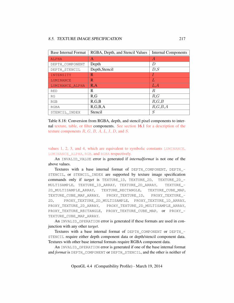
8.5. TEXTURE IMAGE SPECIFICATION 217
Base Internal Format RGBA, Depth, and Stencil Values Internal ComponentsALPHA A A
DEPTH_COMPONENT Depth D
DEPTH_STENCIL Depth,Stencil D,SINTENSITY R I
LUMINANCE R L
LUMINANCE_ALPHA R,A L,ARED R R
RG R,G R,GRGB R,G,B R,G,BRGBA R,G,B,A R,G,B,ASTENCIL_INDEX Stencil S
Table 8.18: Conversion from RGBA, depth, and stencil pixel components to inter-nal texture, table, or filter components. See section 16.1 for a description of thetexture components R, G, B, A, L, I , D, and S.
values 1, 2, 3, and 4, which are equivalent to symbolic constants LUMINANCE,LUMINANCE_ALPHA, RGB, and RGBA respectively.
An INVALID_VALUE error is generated if internalformat is not one of theabove values.
Textures with a base internal format of DEPTH_COMPONENT, DEPTH_-
STENCIL, or STENCIL_INDEX are supported by texture image specificationcommands only if target is TEXTURE_1D, TEXTURE_2D, TEXTURE_2D_-
MULTISAMPLE, TEXTURE_1D_ARRAY, TEXTURE_2D_ARRAY, TEXTURE_-
2D_MULTISAMPLE_ARRAY, TEXTURE_RECTANGLE, TEXTURE_CUBE_MAP,TEXTURE_CUBE_MAP_ARRAY, PROXY_TEXTURE_1D, PROXY_TEXTURE_-
2D, PROXY_TEXTURE_2D_MULTISAMPLE, PROXY_TEXTURE_1D_ARRAY,PROXY_TEXTURE_2D_ARRAY, PROXY_TEXTURE_2D_MULTISAMPLE_ARRAY,PROXY_TEXTURE_RECTANGLE, PROXY_TEXTURE_CUBE_MAP, or PROXY_-
TEXTURE_CUBE_MAP_ARRAY.An INVALID_OPERATION error is generated if these formats are used in con-
junction with any other target.Textures with a base internal format of DEPTH_COMPONENT or DEPTH_-
STENCIL require either depth component data or depth/stencil component data.Textures with other base internal formats require RGBA component data.
An INVALID_OPERATION error is generated if one of the base internal formatand format is DEPTH_COMPONENT or DEPTH_STENCIL, and the other is neither of
OpenGL 4.4 (Compatibility Profile) - March 19, 2014
8.5. TEXTURE IMAGE SPECIFICATION 218
these values.Textures with integer internal formats (see tables 8.19- 8.20) require integer
data.An INVALID_OPERATION error is generated if the internal format is integer
and format is not one of the integer formats listed in table 8.8, or if the internalformat is not integer and format is an integer format.
In addition to the specific compressed internal formats listed in table 8.22, theGL provides a mechanism to query token values for specific compressed internalformats, suitable for general-purpose1 usage. Formats with restrictions that need tobe specifically understood prior to use will not be returned by this query. The num-ber of specific compressed internal formats is obtained by querying the value ofNUM_COMPRESSED_TEXTURE_FORMATS. The set of specific compressed internalformats is obtained by querying COMPRESSED_TEXTURE_FORMATS with GetInte-gerv, returning an array containing that number of values.
Generic compressed internal formats are never used directly as the internal for-mats of texture images. If internalformat is one of the six generic compressedinternal formats, its value is replaced by the symbolic constant for a specific com-pressed internal format of the GL’s choosing with the same base internal format.If no specific compressed format is available, internalformat is instead replaced bythe corresponding base internal format. If internalformat is given as or mappedto a specific compressed internal format, but the GL can not support images com-pressed in the chosen internal format for any reason (e.g., the compression formatmight not support 3D textures or borders), internalformat is replaced by the corre-sponding base internal format and the texture image will not be compressed by theGL.
Errors
An INVALID_OPERATION error is generated by TexImage3D if internal-format is one of the EAC, ETC2, or RGTC compressed formats and eitherborder is non-zero, or target is not TEXTURE_2D_ARRAY.
The internal component resolution is the number of bits allocated to each valuein a texture image. If internalformat is specified as a base internal format, the GLstores the resulting texture with internal component resolutions of its own choos-ing. If a sized internal format is specified, the mapping of the R, G, B, A, depth,and stencil values to texture components is equivalent to the mapping of the cor-responding base internal format’s components, as specified in table 8.18; the type
1 These queries have been deprecated in OpenGL 4.2, because the vagueness of the term “general-purpose” makes it possible for implementations to choose to return no formats from the query.
OpenGL 4.4 (Compatibility Profile) - March 19, 2014
8.5. TEXTURE IMAGE SPECIFICATION 219
(unsigned int, float, etc.) is assigned the same type specified by internalformat;and the memory allocation per texture component is assigned by the GL to matchthe allocations listed in tables 8.19- 8.21 as closely as possible. (The definition ofclosely is left up to the implementation. However, a non-zero number of bits mustbe allocated for each component whose desired allocation in tables 8.19- 8.21 isnon-zero, and zero bits must be allocated for all other components).
8.5.1 Required Texture Formats
Implementations are required to support at least one allocation of internal com-ponent resolution for each type (unsigned int, float, etc.) for each base internalformat.
In addition, implementations are required to support the following sized andcompressed internal formats. Requesting one of these sized internal formats forany texture type will allocate at least the internal component sizes, and exactly thecomponent types shown for that format in the corresponding table:
• Color formats which are checked in the “Req. tex.” column of table 8.19.
• All of the specific compressed texture formats in table 8.22.
• Depth, depth+stencil, and stencil formats which are checked in the “Req.format” column of table 8.21.
8.5.2 Encoding of Special Internal Formats
If internalformat is R11F_G11F_B10F, the red, green, and blue bits are convertedto unsigned 11-bit, unsigned 11-bit, and unsigned 10-bit floating-point values asdescribed in sections 2.3.3.3 and 2.3.3.4.
If internalformat is RGB9_E5, the red, green, and blue bits are converted to ashared exponent format according to the following procedure:
Components red, green, and blue are first clamped (in the process, mappingNaN to zero) as follows:
redc = max(0,min(sharedexpmax, red))
greenc = max(0,min(sharedexpmax, green))
bluec = max(0,min(sharedexpmax, blue))
where
sharedexpmax =(2N − 1)
2N2Emax−B.
OpenGL 4.4 (Compatibility Profile) - March 19, 2014
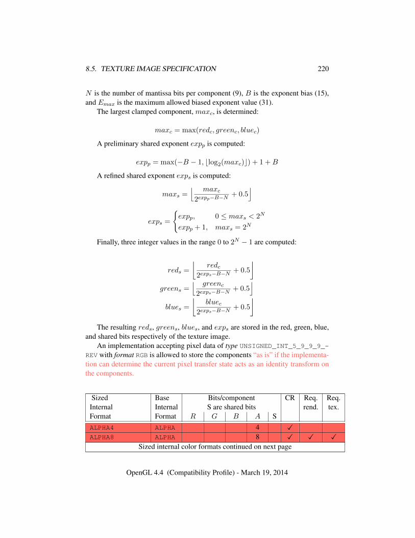
8.5. TEXTURE IMAGE SPECIFICATION 220
N is the number of mantissa bits per component (9), B is the exponent bias (15),and Emax is the maximum allowed biased exponent value (31).
The largest clamped component, maxc, is determined:
maxc = max(redc, greenc, bluec)
A preliminary shared exponent expp is computed:
expp = max(−B − 1, blog2(maxc)c) + 1 +B
A refined shared exponent exps is computed:
maxs =⌊ maxc
2expp−B−N+ 0.5
⌋
exps =
{expp, 0 ≤ maxs < 2N
expp + 1, maxs = 2N
Finally, three integer values in the range 0 to 2N − 1 are computed:
reds =
⌊redc
2exps−B−N+ 0.5
⌋greens =
⌊ greenc2exps−B−N
+ 0.5⌋
blues =
⌊bluec
2exps−B−N+ 0.5
⌋The resulting reds, greens, blues, and exps are stored in the red, green, blue,
and shared bits respectively of the texture image.An implementation accepting pixel data of type UNSIGNED_INT_5_9_9_9_-
REV with format RGB is allowed to store the components “as is” if the implementa-tion can determine the current pixel transfer state acts as an identity transform onthe components.
Sized Base Bits/component CR Req. Req.Internal Internal S are shared bits rend. tex.Format Format R G B A SALPHA4 ALPHA 4 �ALPHA8 ALPHA 8 � � �
Sized internal color formats continued on next page
OpenGL 4.4 (Compatibility Profile) - March 19, 2014
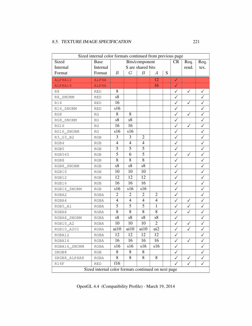
8.5. TEXTURE IMAGE SPECIFICATION 221
Sized internal color formats continued from previous pageSized Base Bits/component CR Req. Req.Internal Internal S are shared bits rend. tex.Format Format R G B A SALPHA12 ALPHA 12 �ALPHA16 ALPHA 16 �R8 RED 8 � � �R8_SNORM RED s8 � �R16 RED 16 � � �R16_SNORM RED s16 � �RG8 RG 8 8 � � �RG8_SNORM RG s8 s8 � �RG16 RG 16 16 � � �RG16_SNORM RG s16 s16 � �R3_G3_B2 RGB 3 3 2 � �RGB4 RGB 4 4 4 � �RGB5 RGB 5 5 5 � �RGB565 RGB 5 6 5 � � �RGB8 RGB 8 8 8 � �RGB8_SNORM RGB s8 s8 s8 � �RGB10 RGB 10 10 10 � �RGB12 RGB 12 12 12 � �RGB16 RGB 16 16 16 � �RGB16_SNORM RGB s16 s16 s16 � �RGBA2 RGBA 2 2 2 2 � �RGBA4 RGBA 4 4 4 4 � � �RGB5_A1 RGBA 5 5 5 1 � � �RGBA8 RGBA 8 8 8 8 � � �RGBA8_SNORM RGBA s8 s8 s8 s8 � �RGB10_A2 RGBA 10 10 10 2 � � �RGB10_A2UI RGBA ui10 ui10 ui10 ui2 � � �RGBA12 RGBA 12 12 12 12 � �RGBA16 RGBA 16 16 16 16 � � �RGBA16_SNORM RGBA s16 s16 s16 s16 � �SRGB8 RGB 8 8 8 � �SRGB8_ALPHA8 RGBA 8 8 8 8 � � �R16F RED f16 � � �
Sized internal color formats continued on next page
OpenGL 4.4 (Compatibility Profile) - March 19, 2014
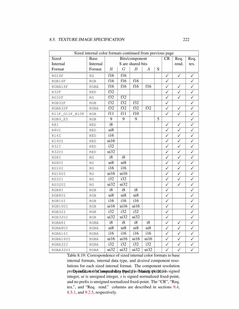
8.5. TEXTURE IMAGE SPECIFICATION 222
Sized internal color formats continued from previous pageSized Base Bits/component CR Req. Req.Internal Internal S are shared bits rend. tex.Format Format R G B A SRG16F RG f16 f16 � � �RGB16F RGB f16 f16 f16 � �RGBA16F RGBA f16 f16 f16 f16 � � �R32F RED f32 � � �RG32F RG f32 f32 � � �RGB32F RGB f32 f32 f32 � �RGBA32F RGBA f32 f32 f32 f32 � � �R11F_G11F_B10F RGB f11 f11 f10 � � �RGB9_E5 RGB 9 9 9 5 �R8I RED i8 � � �R8UI RED ui8 � � �R16I RED i16 � � �R16UI RED ui16 � � �R32I RED i32 � � �R32UI RED ui32 � � �RG8I RG i8 i8 � � �RG8UI RG ui8 ui8 � � �RG16I RG i16 i16 � � �RG16UI RG ui16 ui16 � � �RG32I RG i32 i32 � � �RG32UI RG ui32 ui32 � � �RGB8I RGB i8 i8 i8 � �RGB8UI RGB ui8 ui8 ui8 � �RGB16I RGB i16 i16 i16 � �RGB16UI RGB ui16 ui16 ui16 � �RGB32I RGB i32 i32 i32 � �RGB32UI RGB ui32 ui32 ui32 � �RGBA8I RGBA i8 i8 i8 i8 � � �RGBA8UI RGBA ui8 ui8 ui8 ui8 � � �RGBA16I RGBA i16 i16 i16 i16 � � �RGBA16UI RGBA ui16 ui16 ui16 ui16 � � �RGBA32I RGBA i32 i32 i32 i32 � � �RGBA32UI RGBA ui32 ui32 ui32 ui32 � � �
Table 8.19: Correspondence of sized internal color formats to baseinternal formats, internal data type, and desired component reso-lutions for each sized internal format. The component resolutionprefix indicates the internal data type: f is floating-point, i is signedinteger, ui is unsigned integer, s is signed normalized fixed-point,and no prefix is unsigned normalized fixed-point. The “CR”, “Req.tex.”, and “Req. rend.” columns are described in sections 9.4,8.5.1, and 9.2.5, respectively.
OpenGL 4.4 (Compatibility Profile) - March 19, 2014
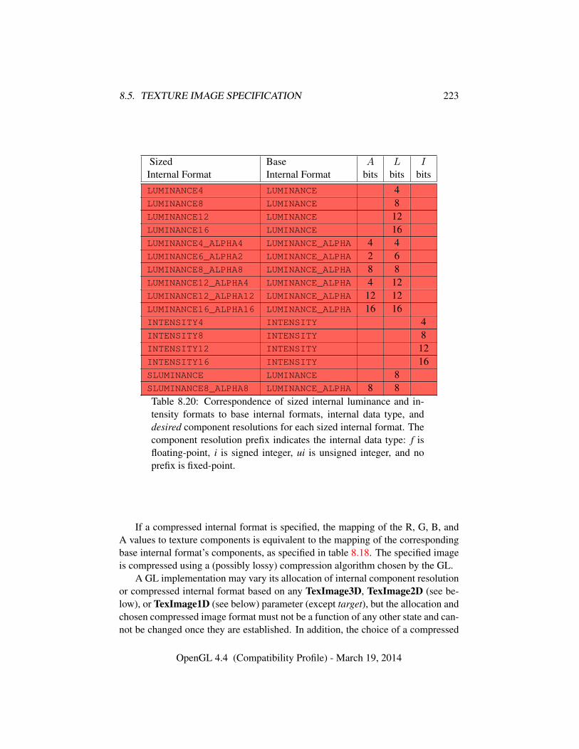
8.5. TEXTURE IMAGE SPECIFICATION 223
Sized Base A L IInternal Format Internal Format bits bits bitsLUMINANCE4 LUMINANCE 4LUMINANCE8 LUMINANCE 8LUMINANCE12 LUMINANCE 12LUMINANCE16 LUMINANCE 16LUMINANCE4_ALPHA4 LUMINANCE_ALPHA 4 4LUMINANCE6_ALPHA2 LUMINANCE_ALPHA 2 6LUMINANCE8_ALPHA8 LUMINANCE_ALPHA 8 8LUMINANCE12_ALPHA4 LUMINANCE_ALPHA 4 12LUMINANCE12_ALPHA12 LUMINANCE_ALPHA 12 12LUMINANCE16_ALPHA16 LUMINANCE_ALPHA 16 16INTENSITY4 INTENSITY 4INTENSITY8 INTENSITY 8INTENSITY12 INTENSITY 12INTENSITY16 INTENSITY 16SLUMINANCE LUMINANCE 8SLUMINANCE8_ALPHA8 LUMINANCE_ALPHA 8 8Table 8.20: Correspondence of sized internal luminance and in-tensity formats to base internal formats, internal data type, anddesired component resolutions for each sized internal format. Thecomponent resolution prefix indicates the internal data type: f isfloating-point, i is signed integer, ui is unsigned integer, and noprefix is fixed-point.
If a compressed internal format is specified, the mapping of the R, G, B, andA values to texture components is equivalent to the mapping of the correspondingbase internal format’s components, as specified in table 8.18. The specified imageis compressed using a (possibly lossy) compression algorithm chosen by the GL.
A GL implementation may vary its allocation of internal component resolutionor compressed internal format based on any TexImage3D, TexImage2D (see be-low), or TexImage1D (see below) parameter (except target), but the allocation andchosen compressed image format must not be a function of any other state and can-not be changed once they are established. In addition, the choice of a compressed
OpenGL 4.4 (Compatibility Profile) - March 19, 2014
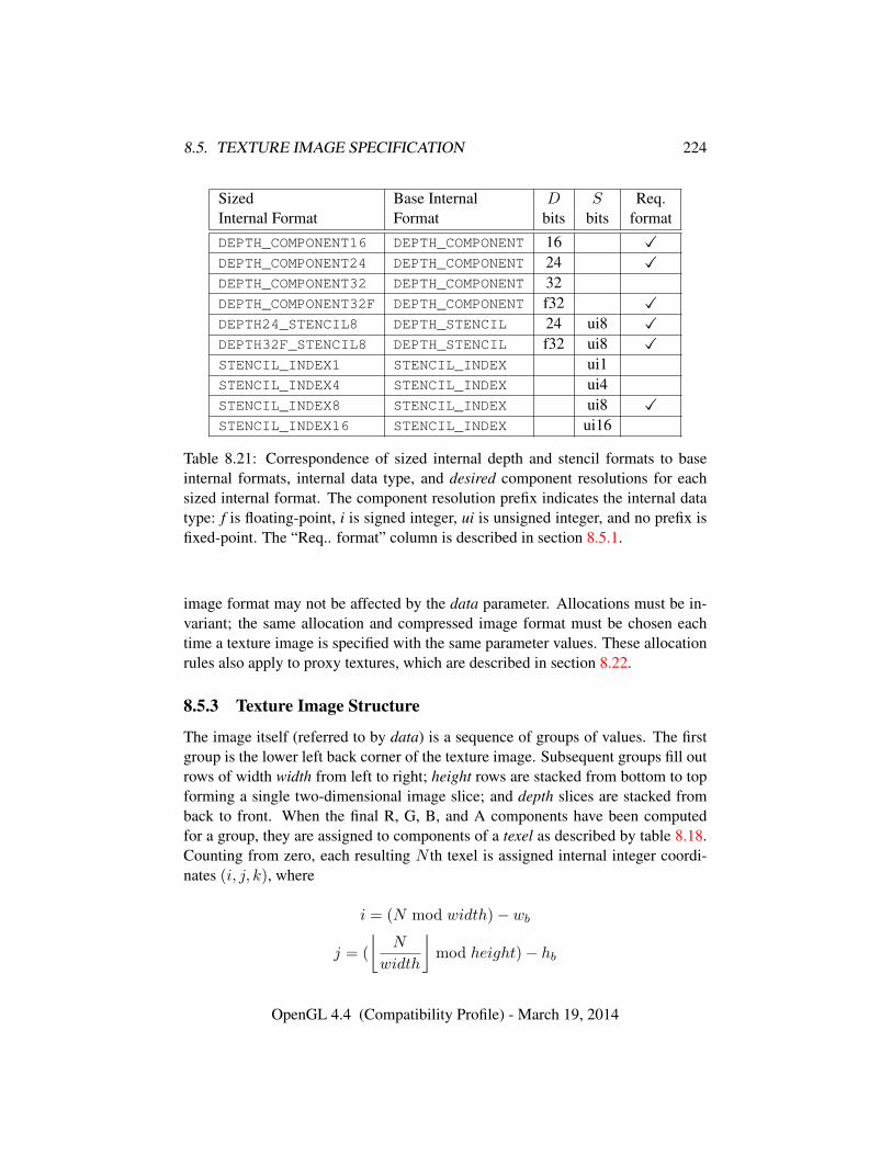
8.5. TEXTURE IMAGE SPECIFICATION 224
Sized Base Internal D S Req.Internal Format Format bits bits formatDEPTH_COMPONENT16 DEPTH_COMPONENT 16 �DEPTH_COMPONENT24 DEPTH_COMPONENT 24 �DEPTH_COMPONENT32 DEPTH_COMPONENT 32DEPTH_COMPONENT32F DEPTH_COMPONENT f32 �DEPTH24_STENCIL8 DEPTH_STENCIL 24 ui8 �DEPTH32F_STENCIL8 DEPTH_STENCIL f32 ui8 �STENCIL_INDEX1 STENCIL_INDEX ui1STENCIL_INDEX4 STENCIL_INDEX ui4STENCIL_INDEX8 STENCIL_INDEX ui8 �STENCIL_INDEX16 STENCIL_INDEX ui16
Table 8.21: Correspondence of sized internal depth and stencil formats to baseinternal formats, internal data type, and desired component resolutions for eachsized internal format. The component resolution prefix indicates the internal datatype: f is floating-point, i is signed integer, ui is unsigned integer, and no prefix isfixed-point. The “Req.. format” column is described in section 8.5.1.
image format may not be affected by the data parameter. Allocations must be in-variant; the same allocation and compressed image format must be chosen eachtime a texture image is specified with the same parameter values. These allocationrules also apply to proxy textures, which are described in section 8.22.
8.5.3 Texture Image Structure
The image itself (referred to by data) is a sequence of groups of values. The firstgroup is the lower left back corner of the texture image. Subsequent groups fill outrows of width width from left to right; height rows are stacked from bottom to topforming a single two-dimensional image slice; and depth slices are stacked fromback to front. When the final R, G, B, and A components have been computedfor a group, they are assigned to components of a texel as described by table 8.18.Counting from zero, each resulting N th texel is assigned internal integer coordi-nates (i, j, k), where
i = (N mod width)− wb
j = (
⌊N
width
⌋mod height)− hb
OpenGL 4.4 (Compatibility Profile) - March 19, 2014
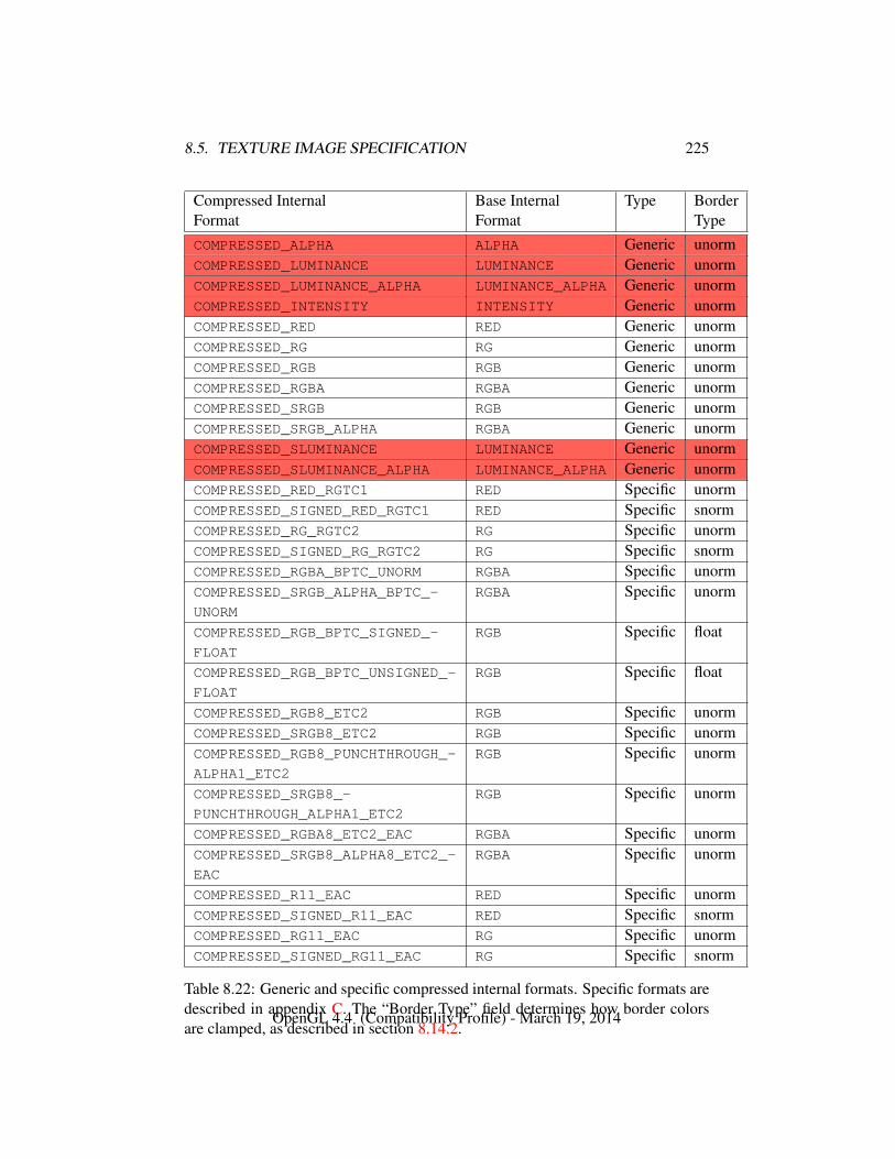
8.5. TEXTURE IMAGE SPECIFICATION 225
Compressed Internal Base Internal Type BorderFormat Format TypeCOMPRESSED_ALPHA ALPHA Generic unormCOMPRESSED_LUMINANCE LUMINANCE Generic unormCOMPRESSED_LUMINANCE_ALPHA LUMINANCE_ALPHA Generic unormCOMPRESSED_INTENSITY INTENSITY Generic unormCOMPRESSED_RED RED Generic unormCOMPRESSED_RG RG Generic unormCOMPRESSED_RGB RGB Generic unormCOMPRESSED_RGBA RGBA Generic unormCOMPRESSED_SRGB RGB Generic unormCOMPRESSED_SRGB_ALPHA RGBA Generic unormCOMPRESSED_SLUMINANCE LUMINANCE Generic unormCOMPRESSED_SLUMINANCE_ALPHA LUMINANCE_ALPHA Generic unormCOMPRESSED_RED_RGTC1 RED Specific unormCOMPRESSED_SIGNED_RED_RGTC1 RED Specific snormCOMPRESSED_RG_RGTC2 RG Specific unormCOMPRESSED_SIGNED_RG_RGTC2 RG Specific snormCOMPRESSED_RGBA_BPTC_UNORM RGBA Specific unormCOMPRESSED_SRGB_ALPHA_BPTC_-
UNORM
RGBA Specific unorm
COMPRESSED_RGB_BPTC_SIGNED_-
FLOAT
RGB Specific float
COMPRESSED_RGB_BPTC_UNSIGNED_-
FLOAT
RGB Specific float
COMPRESSED_RGB8_ETC2 RGB Specific unormCOMPRESSED_SRGB8_ETC2 RGB Specific unormCOMPRESSED_RGB8_PUNCHTHROUGH_-
ALPHA1_ETC2
RGB Specific unorm
COMPRESSED_SRGB8_-
PUNCHTHROUGH_ALPHA1_ETC2
RGB Specific unorm
COMPRESSED_RGBA8_ETC2_EAC RGBA Specific unormCOMPRESSED_SRGB8_ALPHA8_ETC2_-
EAC
RGBA Specific unorm
COMPRESSED_R11_EAC RED Specific unormCOMPRESSED_SIGNED_R11_EAC RED Specific snormCOMPRESSED_RG11_EAC RG Specific unormCOMPRESSED_SIGNED_RG11_EAC RG Specific snorm
Table 8.22: Generic and specific compressed internal formats. Specific formats aredescribed in appendix C. The “Border Type” field determines how border colorsare clamped, as described in section 8.14.2.
OpenGL 4.4 (Compatibility Profile) - March 19, 2014
8.5. TEXTURE IMAGE SPECIFICATION 226
k = (
⌊N
width× height
⌋mod depth)− db
and wb, hb, and db are the specified border width, height, and depth. wb and hb arethe specified border value; db is the specified border value if target is TEXTURE_-3D, or zero if target is TEXTURE_2D_ARRAY or TEXTURE_CUBE_MAP_ARRAY.Thus the last two-dimensional image slice of the three-dimensional image is in-dexed with the highest value of k.
When target is TEXTURE_CUBE_MAP_ARRAY. specifying a cube map array tex-ture, k refers to a layer-face. The layer is given by
layer =
⌊k
6
⌋,
and the face is given by
face = k mod 6.
The face number corresponds to the cube map faces as shown in table 9.2.If the internal data type of the image array is signed or unsigned normalized
fixed-point, each color component is converted using equation 2.4 or 2.3, respec-tively. If the internal type is floating-point or integer, components are clampedto the representable range of the corresponding internal component, but are notconverted.
The level argument to TexImage3D is an integer level-of-detail number. Levelsof detail are discussed in section 8.14.3. The main texture image has a level ofdetail number of zero.
An INVALID_VALUE error is generated if a negative level-of-detail is specified,The border argument to TexImage3D is a border width. The significance of
borders is described below. The border width affects the dimensions of the textureimage: let
ws = wt + 2wb
hs = ht + 2hb
ds = dt + 2db
(8.3)
where ws, hs, and ds are the specified image width, height, and depth, and wt,ht, and dt are the dimensions of the texture image internal to the border.
An INVALID_VALUE error is generated if wt, ht, or dt are negative.An image with zero width, height, or depth indicates the null texture. If
the null texture is specified for the level-of-detail specified by texture parameterTEXTURE_BASE_LEVEL (see section 8.10), it is as if texturing were disabled.
OpenGL 4.4 (Compatibility Profile) - March 19, 2014
8.5. TEXTURE IMAGE SPECIFICATION 227
The maximum border width bt is 1.An INVALID_VALUE error is generated if border is negative or greater than bt.The maximum allowable width, height, or depth of a texel array for a three-
dimensional texture is an implementation-dependent function of the level-of-detailand internal format of the resulting image array. It must be at least 2k−lod + 2btfor image arrays of level-of-detail 0 through k, where k is log2 of the value ofMAX_3D_TEXTURE_SIZE, lod is the level-of-detail of the image array, and bt isthe maximum border width. It may be zero for image arrays of any level-of-detailgreater than k.
An INVALID_VALUE error is generated if width, height, or depth exceed thecorresponding maximum size.
As described in section 8.17, these implementation-dependent limits may beconfigured to reject textures at level one or greater unless a mipmap complete setof image arrays consistent with the specified sizes can be supported.
An INVALID_VALUE error is generated if target is TEXTURE_CUBE_MAP_-
ARRAY or PROXY_TEXTURE_CUBE_MAP_ARRAY, and width and height are notequal.
An INVALID_VALUE error is generated if depth is not a multiple of six, indi-cating 6N layer-faces in the cube map array.
An INVALID_OPERATION error is generated if a pixel unpack buffer object isbound and storing texture data would access memory beyond the end of the pixelunpack buffer.
In a similar fashion, the maximum allowable width of a texel array for a one- ortwo-dimensional, one- or two-dimensional array, two-dimensional multisample, ortwo-dimensional multisample array texture, and the maximum allowable height ofa two-dimensional, two-dimensional array, two-dimensional multisample, or two-dimensional multisample array texture, must be at least 2k−lod + 2bt for imagearrays of level 0 through k, where k is the log base 2 of MAX_TEXTURE_SIZE.
The maximum allowable width and height of a cube map or cube map arraytexture must be the same, and must be at least 2k−lod + 2bt for image arrays level 0through k, where k is the log base 2 of the value of MAX_CUBE_MAP_TEXTURE_-SIZE. The maximum number of layers for one- and two-dimensional array textures(height or depth, respectively), and the maximum number of layer-faces for cubemap array textures (depth), must be at least the value of MAX_ARRAY_TEXTURE_-LAYERS for all levels.
The maximum allowable width and height of a rectangle texture image musteach be at least the value of the implementation-dependent constant MAX_-
RECTANGLE_TEXTURE_SIZE.The command
OpenGL 4.4 (Compatibility Profile) - March 19, 2014
8.5. TEXTURE IMAGE SPECIFICATION 228
void TexImage2D( enum target, int level, int internalformat,sizei width, sizei height, int border, enum format,enum type, const void *data );
is used to specify a two-dimensional texture image. target must be one ofTEXTURE_2D for a two-dimensional texture, TEXTURE_1D_ARRAY for a one-dimensional array texture, TEXTURE_RECTANGLE for a rectangle texture, or oneof the cube map face targets from table 8.26 for a cube map texture. Addi-tionally, target may be either PROXY_TEXTURE_2D for a two-dimensional proxytexture, PROXY_TEXTURE_1D_ARRAY for a one-dimensional proxy array tex-ture, PROXY_TEXTURE_RECTANGLE for a rectangle proxy texture, or PROXY_-TEXTURE_CUBE_MAP for a cube map proxy texture in the special case discussedin section 8.22. The other parameters match the corresponding parameters of Tex-Image3D.
For the purposes of decoding the texture image, TexImage2D is equivalent tocalling TexImage3D with corresponding arguments and depth of 1, except that
• The border depth, db, is zero, and the depth of the image is always oneregardless of the value of border.
• The border height, hb, is zero if target is TEXTURE_1D_ARRAY, and borderotherwise.
• Convolution will be performed on the image (possibly changing its widthand height) if SEPARABLE_2D or CONVOLUTION_2D is enabled.
• UNPACK_SKIP_IMAGES is ignored.
A two-dimensional or rectangle texture consists of a single two-dimensionaltexture image. A cube map texture is a set of six two-dimensional texture images.The six cube map texture face targets from table 8.26 form a single cube map tex-ture. These targets each update the corresponding cube map face two-dimensionaltexture image. Note that the cube map face targets are used when specifying, up-dating, or querying one of a cube map’s six two-dimensional images, but whenenabling cube map texturing or binding to a cube map texture object (that is whenthe cube map is accessed as a whole as opposed to a particular two-dimensionalimage), the TEXTURE_CUBE_MAP target is specified.
Errors
An INVALID_ENUM error is generated if target is not one of the valid tar-gets listed above.
An INVALID_VALUE error is generated if target is one of the cube map
OpenGL 4.4 (Compatibility Profile) - March 19, 2014
8.5. TEXTURE IMAGE SPECIFICATION 229
face targets from table 8.26, and width and height are not equal.An INVALID_VALUE error is generated if target is TEXTURE_RECTANGLE
and level is non-zero.An INVALID_VALUE error is generated if target is TEXTURE_RECTANGLE
and border is non-zero.
Finally, the command
void TexImage1D( enum target, int level,int internalformat, sizei width, int border,enum format, enum type, const void *data );
is used to specify a one-dimensional texture image. target must be eitherTEXTURE_1D, or PROXY_TEXTURE_1D in the special case discussed in sec-tion 8.22.
For the purposes of decoding the texture image, TexImage1D is equivalent tocalling TexImage2D with corresponding arguments and height of 1, except that
• The border height and depth (hb and db) are always zero, regardless of thevalue of border.
• Convolution will be performed on the image (possibly changing its width)only if CONVOLUTION_1D is enabled.
The image indicated to the GL by the image pointer is decoded and copiedinto the GL’s internal memory. This copying effectively places the decoded imageinside a border of the maximum allowable width bt whether or not a border hasbeen specified (see figure 8.3)2. If no border or a border smaller than the maxi-mum allowable width has been specified, then the image is still stored as if it weresurrounded by a border of the maximum possible width. Any excess border (whichsurrounds the specified image, including any border) is assigned unspecified val-ues. A two-dimensional texture has a border only at its left, right, top, and bottomends, and a one-dimensional texture has a border only at its left and right ends.
We shall refer to the (possibly border augmented) decoded image as the texelarray. A three-dimensional texel array has width, height, and depth ws, hs, andds as defined in equation 8.3. A two-dimensional texel array has depth ds = 1,with height hs and width ws as above. A rectangle texel array must have zeroborder width, sows and hs equal the specified width and height, respectively, whileds = 1. A one-dimensional texel array has depth ds = 1, height hs = 1, and widthws as above.
2 Figure 8.3 needs to show a three-dimensional texture image.
OpenGL 4.4 (Compatibility Profile) - March 19, 2014
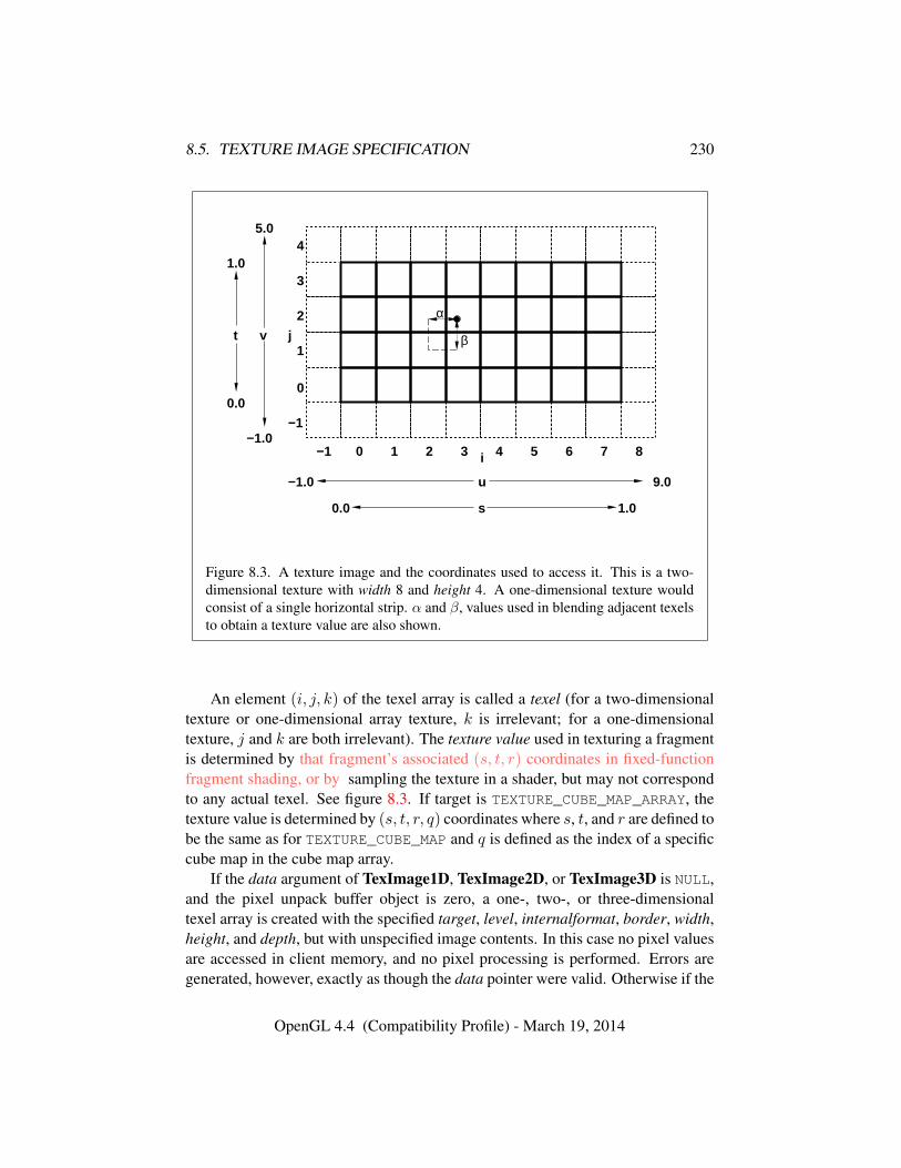
8.5. TEXTURE IMAGE SPECIFICATION 230
i−1 0 1 2 3 4 5 6 7 8
u−1.0 9.0
0.0 1.0s
−1
0
2
1
3
4
j
−1.0
5.0
vt
0.0
1.0
α
β
Figure 8.3. A texture image and the coordinates used to access it. This is a two-dimensional texture with width 8 and height 4. A one-dimensional texture wouldconsist of a single horizontal strip. α and β, values used in blending adjacent texelsto obtain a texture value are also shown.
An element (i, j, k) of the texel array is called a texel (for a two-dimensionaltexture or one-dimensional array texture, k is irrelevant; for a one-dimensionaltexture, j and k are both irrelevant). The texture value used in texturing a fragmentis determined by that fragment’s associated (s, t, r) coordinates in fixed-functionfragment shading, or by sampling the texture in a shader, but may not correspondto any actual texel. See figure 8.3. If target is TEXTURE_CUBE_MAP_ARRAY, thetexture value is determined by (s, t, r, q) coordinates where s, t, and r are defined tobe the same as for TEXTURE_CUBE_MAP and q is defined as the index of a specificcube map in the cube map array.
If the data argument of TexImage1D, TexImage2D, or TexImage3D is NULL,and the pixel unpack buffer object is zero, a one-, two-, or three-dimensionaltexel array is created with the specified target, level, internalformat, border, width,height, and depth, but with unspecified image contents. In this case no pixel valuesare accessed in client memory, and no pixel processing is performed. Errors aregenerated, however, exactly as though the data pointer were valid. Otherwise if the
OpenGL 4.4 (Compatibility Profile) - March 19, 2014
8.6. ALTERNATE TEXTURE IMAGE SPECIFICATION COMMANDS 231
pixel unpack buffer object is non-zero, the data argument is treatedly normally torefer to the beginning of the pixel unpack buffer object’s data.
8.6 Alternate Texture Image Specification Commands
Two-dimensional and one-dimensional texture images may also be specified us-ing image data taken directly from the framebuffer, and rectangular subregions ofexisting texture images may be respecified.
The command
void CopyTexImage2D( enum target, int level,enum internalformat, int x, int y, sizei width,sizei height, int border );
defines a two-dimensional texel array in exactly the manner of TexImage2D, ex-cept that the image data are taken from the framebuffer rather than from clientmemory. target must be one of TEXTURE_2D, TEXTURE_1D_ARRAY, TEXTURE_-RECTANGLE, or one of the cube map face targets from table 8.26. x, y, width,and height correspond precisely to the corresponding arguments to ReadPixels(refer to section 18.2); they specify the image’s width and height, and the lowerleft (x, y) coordinates of the framebuffer region to be copied. The image is takenfrom the framebuffer exactly as if these arguments were passed to CopyPixels(see section 18.3) with argument type set to COLOR, DEPTH, DEPTH_STENCIL, orSTENCIL_INDEX, depending on internalformat, stopping after pixel transfer pro-cessing is complete. RGBA data is taken from the current color buffer, while depthcomponent and stencil index data are taken from the depth and stencil buffers, re-spectively.
Subsequent processing is identical to that described for TexImage2D, begin-ning with clamping of the R, G, B, A, or depth values, and masking of the stencilindex values from the resulting pixel groups. Parameters level, internalformat,and border are specified using the same values, with the same meanings, as thecorresponding arguments of TexImage2D, except that internalformat may not bespecified as 1, 2, 3, or 4.
The constraints on width, height, and border are exactly those for the corre-sponding arguments of TexImage2D.
Errors
An INVALID_ENUM error is generated if target is not TEXTURE_2D,TEXTURE_1D_ARRAY, TEXTURE_RECTANGLE, or one of the cube map face
OpenGL 4.4 (Compatibility Profile) - March 19, 2014
8.6. ALTERNATE TEXTURE IMAGE SPECIFICATION COMMANDS 232
targets from table 8.26.An INVALID_ENUM error is generated if an invalid value is specified for
internalformat.An INVALID_VALUE error is generated if the target parameter to Copy-
TexImage2D is one of the six cube map two-dimensional image targets, andwidth and height are not equal.
An INVALID_OPERATION error is generated under any of the followingconditions:• if depth component data is required and no depth buffer is present
• if stencil index data is required and no stencil buffer is present
• if integer RGBA data is required and the format of the current colorbuffer is not integer
• if floating- or fixed-point RGBA data is required and the format of thecurrent color buffer is integer
• if the value of FRAMEBUFFER_ATTACHMENT_COLOR_ENCODING forthe framebuffer attachment corresponding to the read buffer (see sec-tion 18.2.1) is LINEAR (see section 9.2.3) and internalformat is one ofthe sRGB formats in table 8.31
• if the value of FRAMEBUFFER_ATTACHMENT_COLOR_ENCODING forthe framebuffer attachment corresponding to the read buffer is SRGB
and internalformat is not one of the sRGB formats in table 8.31.An INVALID_VALUE error is generated if width or height is negative.
The command
void CopyTexImage1D( enum target, int level,enum internalformat, int x, int y, sizei width,int border );
defines a one-dimensional texel array in exactly the manner of TexImage1D, ex-cept that the image data are taken from the framebuffer, rather than from clientmemory. Currently, target must be TEXTURE_1D. For the purposes of decodingthe texture image, CopyTexImage1D is equivalent to calling CopyTexImage2Dwith corresponding arguments and height of 1, except that the height of the imageis always 1, regardless of the value of border. level, internalformat, and border arespecified using the same values, with the same meanings, as the corresponding ar-guments of TexImage1D, except that internalformat may not be specified as 1, 2,
OpenGL 4.4 (Compatibility Profile) - March 19, 2014
8.6. ALTERNATE TEXTURE IMAGE SPECIFICATION COMMANDS 233
3, or 4. The constraints on width and border are exactly those of the correspondingarguments of TexImage1D.
Errors
Six additional commands,
void TexSubImage3D( enum target, int level, int xoffset,int yoffset, int zoffset, sizei width, sizei height,sizei depth, enum format, enum type, constvoid *data );
void TexSubImage2D( enum target, int level, int xoffset,int yoffset, sizei width, sizei height, enum format,enum type, const void *data );
void TexSubImage1D( enum target, int level, int xoffset,sizei width, enum format, enum type, constvoid *data );
void CopyTexSubImage3D( enum target, int level,int xoffset, int yoffset, int zoffset, int x, int y,sizei width, sizei height );
void CopyTexSubImage2D( enum target, int level,int xoffset, int yoffset, int x, int y, sizei width,sizei height );
void CopyTexSubImage1D( enum target, int level,int xoffset, int x, int y, sizei width );
respecify only a rectangular subregion of an existing texel array. No change is madeto the internalformat, width, height, depth, or border parameters of the specifiedtexel array, nor is any change made to texel values outside the specified subregion.
The target arguments of TexSubImage1D and CopyTexSubImage1D mustbe TEXTURE_1D, the target arguments of TexSubImage2D and CopyTex-SubImage2D must be one of TEXTURE_2D, TEXTURE_1D_ARRAY, TEXTURE_-RECTANGLE, or one of the cube map face targets from table 8.26, and the targetarguments of TexSubImage3D and CopyTexSubImage3D must be TEXTURE_3D,TEXTURE_2D_ARRAY, or TEXTURE_CUBE_MAP_ARRAY.
The level parameter of each command specifies the level of the texel array thatis modified.
Errors
An INVALID_VALUE error is generated if level is negative or greater than
OpenGL 4.4 (Compatibility Profile) - March 19, 2014
8.6. ALTERNATE TEXTURE IMAGE SPECIFICATION COMMANDS 234
the log2 of the maximum texture width, height, or depth.An INVALID_VALUE error is generated if target is TEXTURE_RECTANGLE
and level is not zero.
TexSubImage3D arguments width, height, depth, format, and type match thecorresponding arguments to TexImage3D, meaning that they accept the same val-ues, and have the same meanings. Likewise, TexSubImage2D arguments width,height, format, and type match the corresponding arguments to TexImage2D, andTexSubImage1D arguments width, format, and type match the corresponding ar-guments to TexImage1D. The data argument of TexSubImage3D, TexSubIm-age2D, and TexSubImage1D matches the corresponding argument of TexIm-age3D, TexImage2D, and TexImage1D, respectively, except that a NULL pointerdoes not represent unspecified image contents.
CopyTexSubImage3D and CopyTexSubImage2D arguments x, y, width,and height match the corresponding arguments to CopyTexImage2D3. CopyTex-SubImage1D arguments x, y, and width match the corresponding arguments toCopyTexImage1D. Each of the TexSubImage commands interprets and processespixel groups in exactly the manner of its TexImage counterpart, except that the as-signment of R, G, B, A, depth, and stencil index pixel group values to the texturecomponents is controlled by the internalformat of the texel array, not by an argu-ment to the command. The same constraints and errors apply to the TexSubImagecommands’ argument format and the internalformat of the texel array being re-specified as apply to the format and internalformat arguments of its TexImagecounterparts.
Arguments xoffset, yoffset, and zoffset of TexSubImage3D and CopyTex-SubImage3D specify the lower left texel coordinates of a width-wide by height-high by depth-deep rectangular subregion of the texel array. For cube map arraytextures, zoffset is the first layer-face to update, and depth is the number of layer-faces to update. The depth argument associated with CopyTexSubImage3D isalways 1, because framebuffer memory is two-dimensional - only a portion of asingle (s, t) slice of a three-dimensional texture is replaced by CopyTexSubIm-age3D.
Negative values of xoffset, yoffset, and zoffset correspond to the coordinatesof border texels, addressed as in figure 8.3. Taking ws, hs, ds, wb, hb, and db tobe the specified width, height, depth, and border width, border height, and borderdepth of the texel array, and taking x, y, z, w, h, and d to be the xoffset, yoffset,zoffset, width, height, and depth argument values, any of the following relationshipsgenerates an INVALID_VALUE error:
3 Because the framebuffer is inherently two-dimensional, there is no CopyTexImage3D com-mand.
OpenGL 4.4 (Compatibility Profile) - March 19, 2014
8.6. ALTERNATE TEXTURE IMAGE SPECIFICATION COMMANDS 235
x < −wb
x+ w > ws − wb
y < −hby + h > hs − hb
z < −dbz + d > ds − db
Counting from zero, the nth pixel group is assigned to the texel with internal integercoordinates [i, j, k], where
i = x+ (n mod w)
j = y + (b nwc mod h)
k = z + (b n
width ∗ heightc mod d
Arguments xoffset and yoffset of TexSubImage2D and CopyTexSubImage2Dspecify the lower left texel coordinates of a width-wide by height-high rectangularsubregion of the texel array. Negative values of xoffset and yoffset correspond tothe coordinates of border texels, addressed as in figure 8.3. Taking ws, hs, and bsto be the specified width, height, and border width of the texel array, and taking x,y, w, and h to be the xoffset, yoffset, width, and height argument values, any of thefollowing relationships generates an INVALID_VALUE error:
x < −bsx+ w > ws − bs
y < −bsy + h > hs − bs
Counting from zero, the nth pixel group is assigned to the texel with internal integercoordinates [i, j], where
i = x+ (n mod w)
j = y + (b nwc mod h)
The xoffset argument of TexSubImage1D and CopyTexSubImage1D speci-fies the left texel coordinate of a width-wide subregion of the texel array. Negative
OpenGL 4.4 (Compatibility Profile) - March 19, 2014
8.6. ALTERNATE TEXTURE IMAGE SPECIFICATION COMMANDS 236
values of xoffset correspond to the coordinates of border texels. Taking ws and bsto be the specified width and border width of the texel array, and x and w to be thexoffset and width argument values, either of the following relationships generatesan INVALID_VALUE error:
x < −bsx+ w > ws − bs
Counting from zero, the nth pixel group is assigned to the texel with internal integercoordinates [i], where
i = x+ (n mod w)
Texture images with compressed internal formats may be stored in such a waythat it is not possible to modify an image with subimage commands without havingto decompress and recompress the texture image. Even if the image were modi-fied in this manner, it may not be possible to preserve the contents of some ofthe texels outside the region being modified. To avoid these complications, theGL does not support arbitrary modifications to texture images with compressedinternal formats. Calling TexSubImage3D, CopyTexSubImage3D, TexSubIm-age2D, CopyTexSubImage2D, TexSubImage1D, or CopyTexSubImage1D willgenerate an INVALID_OPERATION error if xoffset, yoffset, or zoffset is not equal to−bs (border width). In addition, the contents of any texel outside the region mod-ified by such a call are undefined. These restrictions may be relaxed for specificcompressed internal formats whose images are easily modified.
If the internal format of the texture image being modified is one of the spe-cific compressed formats described in table 8.22, the texture is stored using thecorresponding compressed texture image encoding (see appendix C). Since suchimages are easily edited along 4 × 4 texel boundaries, the limitations on subim-age location and size are relaxed for TexSubImage2D, TexSubImage3D, Copy-TexSubImage2D, and CopyTexSubImage3D. These commands will generate anINVALID_OPERATION error if one of the following conditions occurs:
• width is not a multiple of four, width + xoffset is not equal to the value ofTEXTURE_WIDTH, and either xoffset or yoffset is non-zero.
• height is not a multiple of four, height + yoffset is not equal to the value ofTEXTURE_HEIGHT, and either xoffset or yoffset is non-zero.
• xoffset or yoffset is not a multiple of four.
OpenGL 4.4 (Compatibility Profile) - March 19, 2014
8.7. COMPRESSED TEXTURE IMAGES 237
The contents of any 4 × 4 block of texels of such a compressed texture imagethat does not intersect the area being modified are preserved during valid Tex-SubImage* and CopyTexSubImage* calls.
Errors
An INVALID_FRAMEBUFFER_OPERATION error is generated by Copy-TexSubImage3D, CopyTexImage2D, CopyTexSubImage2D, CopyTex-Image1D, or CopyTexSubImage1D if the object bound to READ_-
FRAMEBUFFER_BINDING is not framebuffer complete (see section 9.4.2)An INVALID_OPERATION error is generated by CopyTexSubImage3D,
CopyTexImage2D, CopyTexSubImage2D, CopyTexImage1D, or Copy-TexSubImage1D if• the read buffer is NONE, or
• the value of READ_FRAMEBUFFER_BINDING is non-zero, and
– the read buffer selects an attachment that has no image attached,or
– the value of SAMPLE_BUFFERS for the read framebuffer is one.
8.6.1 Texture Copying Feedback Loops
Calling CopyTexSubImage3D, CopyTexImage2D,CopyTexSubImage2D, CopyTexImage1D, or CopyTexSubImage1D will resultin undefined behavior if the destination texture image level is also bound to to theselected read buffer (see section 18.2.1) of the read framebuffer. This situation isdiscussed in more detail in the description of feedback loops in section 9.3.2.
8.7 Compressed Texture Images
Texture images may also be specified or modified using image data already storedin a known compressed image format, including the formats defined in appendix Cas well as any additional formats defined by extensions.
The commands
void CompressedTexImage1D( enum target, int level,enum internalformat, sizei width, int border,sizei imageSize, const void *data );
OpenGL 4.4 (Compatibility Profile) - March 19, 2014
8.7. COMPRESSED TEXTURE IMAGES 238
void CompressedTexImage2D( enum target, int level,enum internalformat, sizei width, sizei height,int border, sizei imageSize, const void *data );
void CompressedTexImage3D( enum target, int level,enum internalformat, sizei width, sizei height,sizei depth, int border, sizei imageSize, constvoid *data );
define one-, two-, and three-dimensional texture images, respectively, with incom-ing data stored in a specific compressed image format. The target, level, inter-nalformat, width, height, depth, and border parameters have the same meaningas in TexImage1D, TexImage2D, and TexImage3D, except that compressed rect-angle texture formats are not supported. data refers to compressed image datastored in the specific compressed image format corresponding to internalformat.If a pixel unpack buffer is bound (as indicated by a non-zero value of PIXEL_-UNPACK_BUFFER_BINDING), data is an offset into the pixel unpack buffer and thecompressed data is read from the buffer relative to this offset; otherwise, data isa pointer to client memory and the compressed data is read from client memoryrelative to the pointer.
The compressed image will be decoded according to the specification definingthe internalformat token. Compressed texture images are treated as an array ofimageSize ubytes relative to data.
If the compressed image is not encoded according to the defined image format,the results of the call are undefined.
All pixel transfer modes are ignored when decoding a compressed texture im-age.
If the compressed data are arranged into fixed-size blocks of texels, the pixelstorage modes can be used to select a sub-rectangle from a larger containing rect-angle. These pixel storage modes operate in the same way as they do for TexIm-age*D and as described in section 8.4.4. In the remainder of this section, denoteby bs, bw, bh, and bd the values of pixel storage modes UNPACK_COMPRESSED_-BLOCK_SIZE, UNPACK_COMPRESSED_BLOCK_WIDTH, UNPACK_COMPRESSED_-BLOCK_HEIGHT, and UNPACK_COMPRESSED_BLOCK_DEPTH respectively. bs isthe compressed block size in bytes; bw, bh, and bd are the compressed block width,height, and depth in pixels.
By default the pixel storage modes UNPACK_ROW_LENGTH, UNPACK_SKIP_-ROWS, UNPACK_SKIP_PIXELS, UNPACK_IMAGE_HEIGHT and UNPACK_SKIP_-
IMAGES are ignored for compressed images. To enable UNPACK_SKIP_PIXELS
and UNPACK_ROW_LENGTH, bs and bw must both be non-zero. To also enableUNPACK_SKIP_ROWS and UNPACK_IMAGE_HEIGHT, bh must be non-zero. And
OpenGL 4.4 (Compatibility Profile) - March 19, 2014
8.7. COMPRESSED TEXTURE IMAGES 239
to also enable UNPACK_SKIP_IMAGES, bd must be non-zero. All parameters mustbe consistent with the compressed format to produce the desired results.
Errors
An INVALID_ENUM error is generated if the target parameter to any of theCompressedTexImagenD commands is TEXTURE_RECTANGLE or PROXY_-TEXTURE_RECTANGLE.
An INVALID_ENUM error is generated if internalformat is not a supportedspecific compressed internal format from table 8.22. In particular, this errorwill be generated for any of the generic compressed internal formats.
An INVALID_VALUE error is generated if width, height, depth, or image-Size is negative.
An INVALID_OPERATION error is generated if a pixel unpack buffer ob-ject is bound and data+imageSize is greater than the size of the pixel buffer.
An INVALID_VALUE error is generated if the imageSize parameter is notconsistent with the format, dimensions, and contents of the compressed image.
An INVALID_OPERATION error is generated if any of the following con-ditions are violated when selecting a sub-rectangle from a compressed image:• the value of UNPACK_SKIP_PIXELS must be a multiple of bw;
• the value of UNPACK_SKIP_ROWS must be a multiple of bh for Com-pressedTexImage2D and CompressedTexImage3D;
• the value of UNPACK_SKIP_IMAGES must be a multiple of bd for Com-pressedTexImage3D.
An INVALID_VALUE error is generated if imageSize does not match thefollowing requirements when pixel storage modes are active:
• For CompressedTexImage1D the imageSize parameter must be equalto
bs ×⌈width
bw
⌉• For CompressedTexImage2D the imageSize parameter must be equal
to
bs ×⌈width
bw
⌉×⌈height
bh
⌉
OpenGL 4.4 (Compatibility Profile) - March 19, 2014
8.7. COMPRESSED TEXTURE IMAGES 240
• For CompressedTexImage3D the imageSize parameter must be equalto
bs ×⌈width
bw
⌉×⌈height
bh
⌉×⌈depth
bd
⌉
Based on the definition of unpacking from section 8.4.4 for uncompressed im-ages, unpacking compressed images can be defined where:
• n, the number of elements in a group, is 1
• s, the size of an element, is bs
• l, the number of groups in a row, is
l =
⌈row length
bw
⌉, row length > 0⌈
lengthbw
⌉, otherwise
where row length is the value of UNPACK_ROW_LENGTH.
• a, the value of UNPACK_ALIGNMENT, is ignored and
• k = n× l as is defined for uncompressed images.
Before obtaining the first compressed image block from memory, the datapointer is advanced by
UNPACK SKIP PIXELS
bw× n+
UNPACK SKIP ROWS
bh× k
elements. Then⌈widthbw
⌉blocks are obtained from contiguous blocks in memory
(without advancing the pointer), after which the pointer is advanced by k elements.⌈heightbh
⌉sets of
⌈widthbw
⌉blocks are obtained this way. For three-dimensional com-
pressed images the pointer is advanced by UNPACK SKIP IMAGESbd
times the numberof elements in one two-dimensional image before obtaining the first group frommemory. Then after height rows are obtained the pointer skips over the remaining⌈UNPACK IMAGE HEIGHT
bh
⌉rows, if UNPACK_IMAGE_HEIGHT is positive, before starting
the next two-dimensional image.An INVALID_OPERATION error is generated if any format-specific restrictions
imposed by specific compressed internal formats are violated by the compressedimage specification calls or parameters. For example, a format might be supported
OpenGL 4.4 (Compatibility Profile) - March 19, 2014
8.7. COMPRESSED TEXTURE IMAGES 241
only for 2D textures, or might not allow non-zero border values. Any such restric-tions will be documented in the extension specification defining the compressedinternal format.
Any restrictions imposed by specific compressed internal formats will be in-variant, meaning that if the GL accepts and stores a texture image in compressedform, providing the same image to CompressedTexImage1D, Compressed-TexImage2D, or CompressedTexImage3D will not generate an INVALID_-
OPERATION error if the following restrictions are satisfied:
• data points to a compressed texture image returned by GetCompressedTex-Image (section 8.11).
• target, level, and internalformat match the target, level and format parame-ters provided to the GetCompressedTexImage call returning data.
• width, height, depth, border, internalformat, and imageSize match the valuesof TEXTURE_WIDTH, TEXTURE_HEIGHT, TEXTURE_DEPTH, TEXTURE_-BORDER, TEXTURE_INTERNAL_FORMAT, and TEXTURE_COMPRESSED_-
IMAGE_SIZE for image level level in effect at the time of the GetCom-pressedTexImage call returning data.
This guarantee applies not just to images returned by GetCompressedTexImage,but also to any other properly encoded compressed texture image of the same sizeand format.
If internalformat is one of the specific compressed formats described in ta-ble 8.22, the compressed image data is stored using the corresponding texture im-age encoding (see appendix C). The corresponding compression algorithms sup-port only two-dimensional images without borders, though three-dimensional im-ages can be compressed as multiple slices of compressed two-dimensional BPTCimages.
Errors
An INVALID_ENUM error is generated by CompressedTexImage1D if in-ternalformat is one of the specific compressed formats. OpenGL defines nospecific one-dimensional compressed formats, but such formats may be pro-vided by extensions.
An INVALID_OPERATION error is generated by CompressedTexIm-age2D if internalformat is one of the EAC, ETC2, or RGTC formats and eitherborder is non-zero, or target is TEXTURE_RECTANGLE.
An INVALID_OPERATION error is generated by CompressedTexIm-
OpenGL 4.4 (Compatibility Profile) - March 19, 2014
8.7. COMPRESSED TEXTURE IMAGES 242
age3D if internalformat is one of the EAC, ETC2, or RGTC formats and eitherborder is non-zero, or target is not TEXTURE_2D_ARRAY.
An INVALID_OPERATION error is generated by CompressedTexIm-age2D and CompressedTexImage3D if internalformat is one of the BPTCformats and border is non-zero.
If the data argument of CompressedTexImage1D, CompressedTexImage2D,or CompressedTexImage3D is NULL, and the pixel unpack buffer object is zero, atexel array with unspecified image contents is created, just as when a NULL pointeris passed to TexImage1D, TexImage2D, or TexImage3D.
The commands
void CompressedTexSubImage1D( enum target, int level,int xoffset, sizei width, enum format, sizei imageSize,const void *data );
void CompressedTexSubImage2D( enum target, int level,int xoffset, int yoffset, sizei width, sizei height,enum format, sizei imageSize, const void *data );
void CompressedTexSubImage3D( enum target, int level,int xoffset, int yoffset, int zoffset, sizei width,sizei height, sizei depth, enum format,sizei imageSize, const void *data );
respecify only a rectangular region of an existing texel array, with incoming datastored in a specific compressed image format. The target, level, xoffset, yoff-set, zoffset, width, height, and depth parameters have the same meaning as inTexSubImage1D, TexSubImage2D, and TexSubImage3D. data points to com-pressed image data stored in the compressed image format corresponding to for-mat.
The image pointed to by data and the imageSize parameter are interpretedas though they were provided to CompressedTexImage1D, CompressedTexIm-age2D, and CompressedTexImage3D.
Any restrictions imposed by specific compressed internal formats will beinvariant, meaning that if the GL accepts and stores a texture image in com-pressed form, providing the same image to CompressedTexSubImage1D, Com-pressedTexSubImage2D, CompressedTexSubImage3D will not generate anINVALID_OPERATION error if the following restrictions are satisfied:
• data points to a compressed texture image returned by GetCompressedTex-Image (section 8.11).
OpenGL 4.4 (Compatibility Profile) - March 19, 2014
8.7. COMPRESSED TEXTURE IMAGES 243
• target, level, and format match the target, level and format parameters pro-vided to the GetCompressedTexImage call returning data.
• width, height, depth, format, and imageSize match the values of TEXTURE_-WIDTH, TEXTURE_HEIGHT, TEXTURE_DEPTH, TEXTURE_INTERNAL_-
FORMAT, and TEXTURE_COMPRESSED_IMAGE_SIZE for image level levelin effect at the time of the GetCompressedTexImage call returning data.
• width, height, depth, and format match the values of TEXTURE_WIDTH,TEXTURE_HEIGHT, TEXTURE_DEPTH, and TEXTURE_INTERNAL_FORMAT
currently in effect for image level level.
• xoffset, yoffset, and zoffset are all −b, where b is the value of TEXTURE_-BORDER currently in effect for image level level.
This guarantee applies not just to images returned by GetCompressedTexIm-age, but also to any other properly encoded compressed texture image of the samesize.
If the internal format of the image being modified is one of the specific com-pressed formats described in table 8.22, the texture is stored using the correspond-ing texture image encoding (see appendix C).
Since these specific compressed formats are easily edited along 4 × 4 texelboundaries, the limitations on subimage location and size are relaxed for Com-pressedTexSubImage2D and CompressedTexSubImage3D.
The contents of any 4 × 4 block of texels of a compressed texture image inthese specific compressed formats that does not intersect the area being modifiedare preserved during CompressedTexSubImage* calls.
Errors
An INVALID_ENUM error is generated if target is TEXTURE_RECTANGLEor PROXY_TEXTURE_RECTANGLE,
An INVALID_ENUM error is generated if format is one of the generic com-pressed internal formats.
An INVALID_OPERATION error is generated if format does not match theinternal format of the texture image being modified, since these commands donot provide for image format conversion.
An INVALID_VALUE error is generated if width, height, depth, or image-Size is negative.
An INVALID_VALUE error is generated if imageSize is not consistent withthe format, dimensions, and contents of the compressed image (too little or
OpenGL 4.4 (Compatibility Profile) - March 19, 2014
8.8. MULTISAMPLE TEXTURES 244
too much data),An INVALID_OPERATION error is generated if any format-specific restric-
tions are violated, as with CompressedTexImage calls. Any such restrictionswill be documented in the specification defining the compressed internal for-mat.
An INVALID_OPERATION error is generated if xoffset, yoffset, or zoffsetare not equal to−bs (border width), or if width, height, and depth do not matchthe corresponding dimensions of the texture level. The contents of any texeloutside the region modified by the call are undefined. These restrictions maybe relaxed for specific compressed internal formats whose images are easilymodified.
An INVALID_ENUM error is generated by CompressedTexSubImage1Dif the internal format of the texture bound to target is one of the specific com-pressed formats.
An INVALID_OPERATION error is generated by CompressedTexSubIm-age2D if the internal format of the texture bound to target is one of the EAC,ETC2, or RGTC formats and border is non-zero.
An INVALID_OPERATION error is generated by CompressedTexSubIm-age3D if the internal format of the texture bound to target is one of theEAC, ETC2, or RGTC formats and either border is non-zero, or target is notTEXTURE_2D_ARRAY.
An INVALID_OPERATION error is generated by CompressedTexSubIm-age2D and CompressedTexSubImage3D if the internal format of the texturebound to target is one of the BPTC formats and border is non-zero.
An INVALID_OPERATION error is generated by CompressedTexSubIm-age2D and CompressedTexSubImage3D if any of the following conditionsoccurs:• width is not a multiple of four, and width + xoffset is not equal to the
value of TEXTURE_WIDTH.
• height is not a multiple of four, and height + yoffset is not equal to thevalue of TEXTURE_HEIGHT.
• xoffset or yoffset is not a multiple of four.
8.8 Multisample Textures
In addition to the texture types described in previous sections, two additional typesof textures are supported. A multisample texture is similar to a two-dimensionalor two-dimensional array texture, except it contains multiple samples per texel.
OpenGL 4.4 (Compatibility Profile) - March 19, 2014
8.8. MULTISAMPLE TEXTURES 245
Multisample textures do not have multiple image levels.The commands
void TexImage2DMultisample( enum target, sizei samples,enum internalformat, sizei width, sizei height,boolean fixedsamplelocations );
void TexImage3DMultisample( enum target, sizei samples,enum internalformat, sizei width, sizei height,sizei depth, boolean fixedsamplelocations );
establish the data storage, format, dimensions, and number of samples of amultisample texture’s image. For TexImage2DMultisample, target must beTEXTURE_2D_MULTISAMPLE or PROXY_TEXTURE_2D_MULTISAMPLE and forTexImage3DMultisample target must be TEXTURE_2D_MULTISAMPLE_ARRAY
or PROXY_TEXTURE_2D_MULTISAMPLE_ARRAY. width and height are the dimen-sions in texels of the texture.
samples represents a request for a desired minimum number of samples.Since different implementations may support different sample counts for multi-sampled textures, the actual number of samples allocated for the texture image isimplementation-dependent. However, the resulting value for TEXTURE_SAMPLESis guaranteed to be greater than or equal to samples and no more than the nextlarger sample count supported by the implementation.
If fixedsamplelocations is TRUE, the image will use identical sample locationsand the same number of samples for all texels in the image, and the sample loca-tions will not depend on the internal format or size of the image.
Upon success, TexImage*Multisample deletes any existing image for tar-get and the contents of texels are undefined. TEXTURE_WIDTH, TEXTURE_-HEIGHT, TEXTURE_SAMPLES, TEXTURE_INTERNAL_FORMAT and TEXTURE_-
FIXED_SAMPLE_LOCATIONS are set to width, height, the actual number of sam-ples allocated, internalformat, and fixedsamplelocations respectively.
When a multisample texture is accessed in a shader, the access takes one vectorof integers describing which texel to fetch and an integer corresponding to thesample numbers described in section 14.3.1 describing which sample within thetexel to fetch. No standard sampling instructions are allowed on the multisampletexture targets. Fetching a sample number less than zero, or greater than or equalto the number of samples in the texture, produces undefined results.
Errors
An INVALID_ENUM error is generated if target is not an accepted multi-sample target as described above.
OpenGL 4.4 (Compatibility Profile) - March 19, 2014
8.9. BUFFER TEXTURES 246
An INVALID_VALUE error is generated if width, height, or depth is nega-tive.
An INVALID_VALUE error is generated if samples is zero.An INVALID_VALUE error is generated if width or height is greater than
the value of MAX_TEXTURE_SIZE.An INVALID_VALUE error is generated by TexImage3DMultisample if
depth is greater than the value of MAX_ARRAY_TEXTURE_LAYERS.An INVALID_ENUM error is generated if internalformat is not color-
renderable, depth-renderable, or stencil-renderable (as defined in section 9.4).An INVALID_OPERATION error is generated if samples is greater than the
maximum number of samples supported for this target and internalformat.The maximum number of samples supported can be determined by callingGetInternalformativ with a pname of SAMPLES (see section 22.3).
An INVALID_OPERATION error is generated if the value of TEXTURE_-IMMUTABLE_FORMAT for the texture currently bound to target on the activetexture unit is TRUE.
8.9 Buffer Textures
In addition to one-, two-, and three-dimensional, one- and two-dimensional array,and cube map textures described in previous sections, one additional type of textureis supported. A buffer texture is similar to a one-dimensional texture. However,unlike other texture types, the texel array is not stored as part of the texture. Instead,a buffer object is attached to a buffer texture and the texel array is taken from thatbuffer object’s data store. When the contents of a buffer object’s data store aremodified, those changes are reflected in the contents of any buffer texture to whichthe buffer object is attached. Buffer textures do not have multiple image levels;only a single data store is available.
The command
void TexBufferRange( enum target, enum internalformat,uint buffer, intptr offset, sizeiptr size );
attaches the range of the storage for the buffer object named buffer for size basicmachine units, starting at offset (also in basic machine units) to the active buffertexture, and specifies an internal format for the texel array found in the range ofthe attached buffer object. If buffer is zero, then any buffer object attached to thebuffer texture is detached, the values offset and size are ignored and the state foroffset and size for the buffer texture are reset to zero. target must be TEXTURE_-BUFFER. internalformat specifies the storage format and must be one of the sizedinternal formats found in table 8.23.
OpenGL 4.4 (Compatibility Profile) - March 19, 2014
8.9. BUFFER TEXTURES 247
Errors
An INVALID_ENUM error is generated if target is not TEXTURE_BUFFER.An INVALID_ENUM error is generated if internalformat is not one of the
sized internal formats in table 8.23.An INVALID_OPERATION error is generated if buffer is non-zero, but is
not the name of a buffer object.An INVALID_VALUE error is generated if offset is negative, if size is less
than or equal to zero, or if offset + size is greater than the value of BUFFER_-SIZE for the buffer bound to target.
An INVALID_VALUE error is generated if offset is not an integer multipleof the value of TEXTURE_BUFFER_OFFSET_ALIGNMENT.
The command
void TexBuffer( enum target, enum internalformat,uint buffer );
is equivalent to
TexBufferRange(target, internalformat, buffer, 0, size);
with size set to the value of BUFFER_SIZE for buffer.When a range of the storage of a buffer object is attached to a buffer texture,
the range of the buffer’s data store is taken as the texture’s texel array. The numberof texels in the buffer texture’s texel array is given by⌊
size
components× sizeof(base type)
⌋.
where components and base type are the element count and base type forelements, as specified in table 8.23.
The number of texels in the texel array is then clamped to value of theimplementation-dependent limit MAX_TEXTURE_BUFFER_SIZE. When a buffertexture is accessed in a shader, the results of a texel fetch are undefined if the spec-ified texel coordinate is negative, or greater than or equal to the clamped numberof texels in the texel array.
When a buffer texture is accessed in a shader, an integer is provided to indicatethe texel coordinate being accessed. If no buffer object is bound to the buffer tex-ture, the results of the texel access are undefined. Otherwise, the attached bufferobject’s data store is interpreted as an array of elements of the GL data type cor-responding to internalformat. Each texel consists of one to four elements that are
OpenGL 4.4 (Compatibility Profile) - March 19, 2014
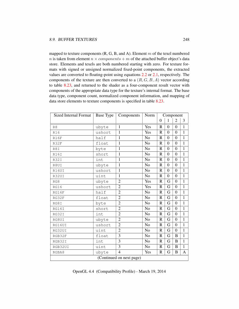
8.9. BUFFER TEXTURES 248
mapped to texture components (R, G, B, and A). Element m of the texel numberedn is taken from element n× components+m of the attached buffer object’s datastore. Elements and texels are both numbered starting with zero. For texture for-mats with signed or unsigned normalized fixed-point components, the extractedvalues are converted to floating-point using equations 2.2 or 2.1, respectively. Thecomponents of the texture are then converted to a (R,G,B,A) vector accordingto table 8.23, and returned to the shader as a four-component result vector withcomponents of the appropriate data type for the texture’s internal format. The basedata type, component count, normalized component information, and mapping ofdata store elements to texture components is specified in table 8.23.
Sized Internal Format Base Type Components Norm Component0 1 2 3
R8 ubyte 1 Yes R 0 0 1R16 ushort 1 Yes R 0 0 1R16F half 1 No R 0 0 1R32F float 1 No R 0 0 1R8I byte 1 No R 0 0 1R16I short 1 No R 0 0 1R32I int 1 No R 0 0 1R8UI ubyte 1 No R 0 0 1R16UI ushort 1 No R 0 0 1R32UI uint 1 No R 0 0 1RG8 ubyte 2 Yes R G 0 1RG16 ushort 2 Yes R G 0 1RG16F half 2 No R G 0 1RG32F float 2 No R G 0 1RG8I byte 2 No R G 0 1RG16I short 2 No R G 0 1RG32I int 2 No R G 0 1RG8UI ubyte 2 No R G 0 1RG16UI ushort 2 No R G 0 1RG32UI uint 2 No R G 0 1RGB32F float 3 No R G B 1RGB32I int 3 No R G B 1RGB32UI uint 3 No R G B 1RGBA8 ubyte 4 Yes R G B A
(Continued on next page)
OpenGL 4.4 (Compatibility Profile) - March 19, 2014
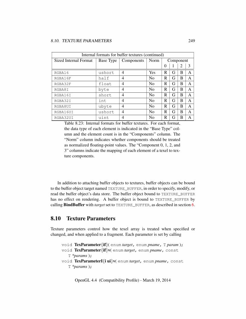
8.10. TEXTURE PARAMETERS 249
Internal formats for buffer textures (continued)Sized Internal Format Base Type Components Norm Component
0 1 2 3RGBA16 ushort 4 Yes R G B ARGBA16F half 4 No R G B ARGBA32F float 4 No R G B ARGBA8I byte 4 No R G B ARGBA16I short 4 No R G B ARGBA32I int 4 No R G B ARGBA8UI ubyte 4 No R G B ARGBA16UI ushort 4 No R G B ARGBA32UI uint 4 No R G B A
Table 8.23: Internal formats for buffer textures. For each format,the data type of each element is indicated in the “Base Type” col-umn and the element count is in the “Components” column. The“Norm” column indicates whether components should be treatedas normalized floating-point values. The “Component 0, 1, 2, and3” columns indicate the mapping of each element of a texel to tex-ture components.
In addition to attaching buffer objects to textures, buffer objects can be boundto the buffer object target named TEXTURE_BUFFER, in order to specify, modify, orread the buffer object’s data store. The buffer object bound to TEXTURE_BUFFER
has no effect on rendering. A buffer object is bound to TEXTURE_BUFFER bycalling BindBuffer with target set to TEXTURE_BUFFER, as described in section 6.
8.10 Texture Parameters
Texture parameters control how the texel array is treated when specified orchanged, and when applied to a fragment. Each parameter is set by calling
void TexParameter{if}( enum target, enum pname, T param );void TexParameter{if}v( enum target, enum pname, const
T *params );void TexParameterI{i ui}v( enum target, enum pname, const
T *params );
OpenGL 4.4 (Compatibility Profile) - March 19, 2014
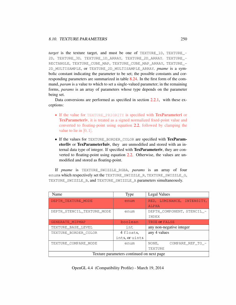
8.10. TEXTURE PARAMETERS 250
target is the texture target, and must be one of TEXTURE_1D, TEXTURE_-
2D, TEXTURE_3D, TEXTURE_1D_ARRAY, TEXTURE_2D_ARRAY. TEXTURE_-
RECTANGLE, TEXTURE_CUBE_MAP, TEXTURE_CUBE_MAP_ARRAY, TEXTURE_-2D_MULTISAMPLE, or TEXTURE_2D_MULTISAMPLE_ARRAY. pname is a sym-bolic constant indicating the parameter to be set; the possible constants and cor-responding parameters are summarized in table 8.24. In the first form of the com-mand, param is a value to which to set a single-valued parameter; in the remainingforms, params is an array of parameters whose type depends on the parameterbeing set.
Data conversions are performed as specified in section 2.2.1, with these ex-ceptions:
• If the value for TEXTURE_PRIORITY is specified with TexParameteri orTexParameteriv, it is treated as a signed normalized fixed-point value andconverted to floating-point using equation 2.2, followed by clamping thevalue to lie in [0, 1].
• If the values for TEXTURE_BORDER_COLOR are specified with TexParam-eterIiv or TexParameterIuiv, they are unmodified and stored with an in-ternal data type of integer. If specified with TexParameteriv, they are con-verted to floating-point using equation 2.2. Otherwise, the values are un-modified and stored as floating-point.
If pname is TEXTURE_SWIZZLE_RGBA, params is an array of fourenums which respectively set the TEXTURE_SWIZZLE_R, TEXTURE_SWIZZLE_G,TEXTURE_SWIZZLE_B, and TEXTURE_SWIZZLE_A parameters simultaneously.
Name Type Legal ValuesDEPTH_TEXTURE_MODE enum RED, LUMINANCE, INTENSITY,
ALPHA
DEPTH_STENCIL_TEXTURE_MODE enum DEPTH_COMPONENT, STENCIL_-INDEX
GENERATE_MIPMAP boolean TRUE or FALSETEXTURE_BASE_LEVEL int any non-negative integerTEXTURE_BORDER_COLOR 4 floats, any 4 values
ints, or uintsTEXTURE_COMPARE_MODE enum NONE, COMPARE_REF_TO_-
TEXTURE
Texture parameters continued on next page
OpenGL 4.4 (Compatibility Profile) - March 19, 2014
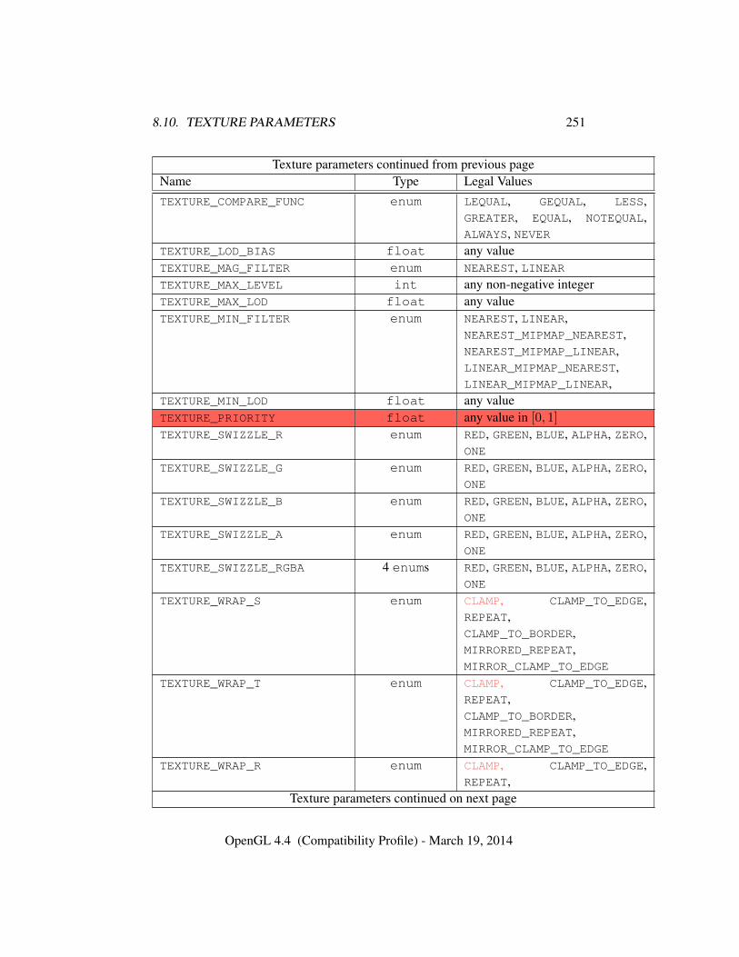
8.10. TEXTURE PARAMETERS 251
Texture parameters continued from previous pageName Type Legal ValuesTEXTURE_COMPARE_FUNC enum LEQUAL, GEQUAL, LESS,
GREATER, EQUAL, NOTEQUAL,ALWAYS, NEVER
TEXTURE_LOD_BIAS float any valueTEXTURE_MAG_FILTER enum NEAREST, LINEARTEXTURE_MAX_LEVEL int any non-negative integerTEXTURE_MAX_LOD float any valueTEXTURE_MIN_FILTER enum NEAREST, LINEAR,
NEAREST_MIPMAP_NEAREST,NEAREST_MIPMAP_LINEAR,LINEAR_MIPMAP_NEAREST,LINEAR_MIPMAP_LINEAR,
TEXTURE_MIN_LOD float any valueTEXTURE_PRIORITY float any value in [0, 1]
TEXTURE_SWIZZLE_R enum RED, GREEN, BLUE, ALPHA, ZERO,ONE
TEXTURE_SWIZZLE_G enum RED, GREEN, BLUE, ALPHA, ZERO,ONE
TEXTURE_SWIZZLE_B enum RED, GREEN, BLUE, ALPHA, ZERO,ONE
TEXTURE_SWIZZLE_A enum RED, GREEN, BLUE, ALPHA, ZERO,ONE
TEXTURE_SWIZZLE_RGBA 4 enums RED, GREEN, BLUE, ALPHA, ZERO,ONE
TEXTURE_WRAP_S enum CLAMP, CLAMP_TO_EDGE,REPEAT,CLAMP_TO_BORDER,MIRRORED_REPEAT,MIRROR_CLAMP_TO_EDGE
TEXTURE_WRAP_T enum CLAMP, CLAMP_TO_EDGE,REPEAT,CLAMP_TO_BORDER,MIRRORED_REPEAT,MIRROR_CLAMP_TO_EDGE
TEXTURE_WRAP_R enum CLAMP, CLAMP_TO_EDGE,REPEAT,
Texture parameters continued on next page
OpenGL 4.4 (Compatibility Profile) - March 19, 2014
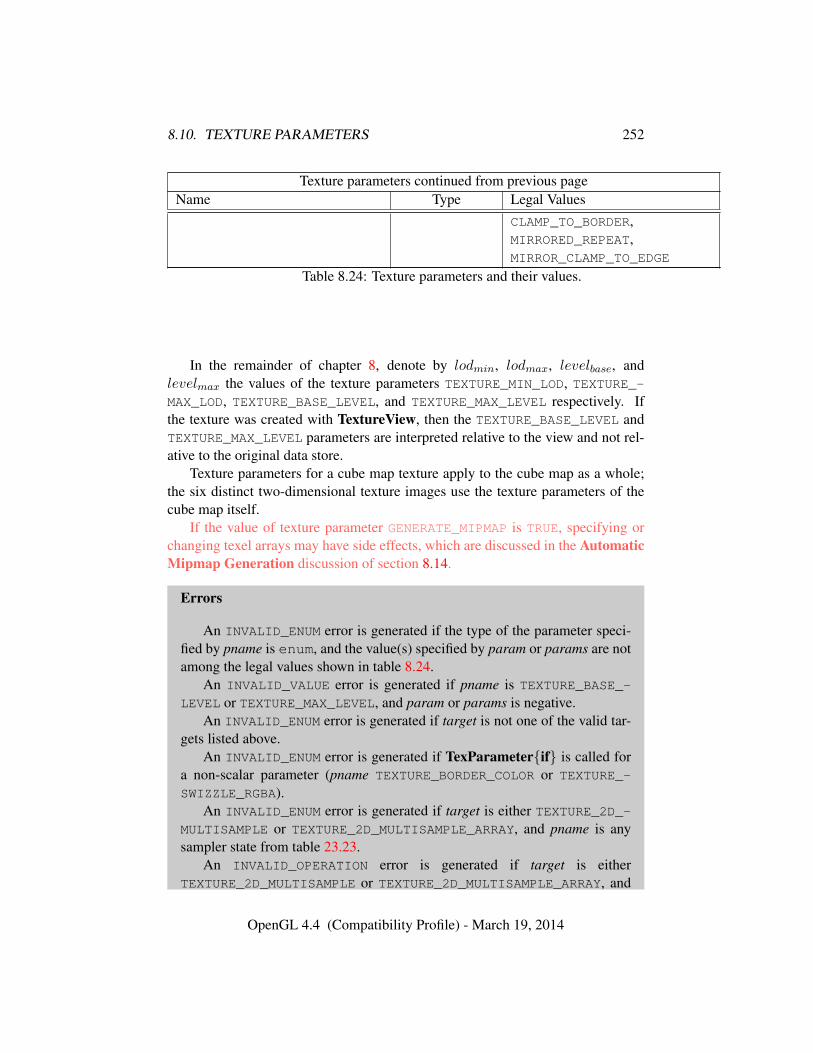
8.10. TEXTURE PARAMETERS 252
Texture parameters continued from previous pageName Type Legal Values
CLAMP_TO_BORDER,MIRRORED_REPEAT,MIRROR_CLAMP_TO_EDGE
Table 8.24: Texture parameters and their values.
In the remainder of chapter 8, denote by lodmin, lodmax, levelbase, andlevelmax the values of the texture parameters TEXTURE_MIN_LOD, TEXTURE_-MAX_LOD, TEXTURE_BASE_LEVEL, and TEXTURE_MAX_LEVEL respectively. Ifthe texture was created with TextureView, then the TEXTURE_BASE_LEVEL andTEXTURE_MAX_LEVEL parameters are interpreted relative to the view and not rel-ative to the original data store.
Texture parameters for a cube map texture apply to the cube map as a whole;the six distinct two-dimensional texture images use the texture parameters of thecube map itself.
If the value of texture parameter GENERATE_MIPMAP is TRUE, specifying orchanging texel arrays may have side effects, which are discussed in the AutomaticMipmap Generation discussion of section 8.14.
Errors
An INVALID_ENUM error is generated if the type of the parameter speci-fied by pname is enum, and the value(s) specified by param or params are notamong the legal values shown in table 8.24.
An INVALID_VALUE error is generated if pname is TEXTURE_BASE_-
LEVEL or TEXTURE_MAX_LEVEL, and param or params is negative.An INVALID_ENUM error is generated if target is not one of the valid tar-
gets listed above.An INVALID_ENUM error is generated if TexParameter{if} is called for
a non-scalar parameter (pname TEXTURE_BORDER_COLOR or TEXTURE_-
SWIZZLE_RGBA).An INVALID_ENUM error is generated if target is either TEXTURE_2D_-
MULTISAMPLE or TEXTURE_2D_MULTISAMPLE_ARRAY, and pname is anysampler state from table 23.23.
An INVALID_OPERATION error is generated if target is eitherTEXTURE_2D_MULTISAMPLE or TEXTURE_2D_MULTISAMPLE_ARRAY, and
OpenGL 4.4 (Compatibility Profile) - March 19, 2014
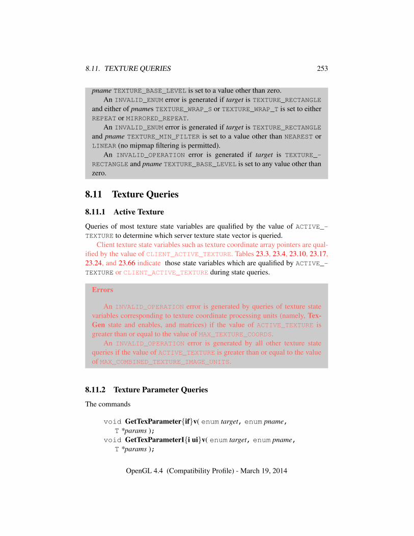
8.11. TEXTURE QUERIES 253
pname TEXTURE_BASE_LEVEL is set to a value other than zero.An INVALID_ENUM error is generated if target is TEXTURE_RECTANGLE
and either of pnames TEXTURE_WRAP_S or TEXTURE_WRAP_T is set to eitherREPEAT or MIRRORED_REPEAT.
An INVALID_ENUM error is generated if target is TEXTURE_RECTANGLEand pname TEXTURE_MIN_FILTER is set to a value other than NEAREST orLINEAR (no mipmap filtering is permitted).
An INVALID_OPERATION error is generated if target is TEXTURE_-
RECTANGLE and pname TEXTURE_BASE_LEVEL is set to any value other thanzero.
8.11 Texture Queries
8.11.1 Active Texture
Queries of most texture state variables are qualified by the value of ACTIVE_-TEXTURE to determine which server texture state vector is queried.
Client texture state variables such as texture coordinate array pointers are qual-ified by the value of CLIENT_ACTIVE_TEXTURE. Tables 23.3, 23.4, 23.10, 23.17,23.24, and 23.66 indicate those state variables which are qualified by ACTIVE_-
TEXTURE or CLIENT_ACTIVE_TEXTURE during state queries.
Errors
An INVALID_OPERATION error is generated by queries of texture statevariables corresponding to texture coordinate processing units (namely, Tex-Gen state and enables, and matrices) if the value of ACTIVE_TEXTURE isgreater than or equal to the value of MAX_TEXTURE_COORDS.
An INVALID_OPERATION error is generated by all other texture statequeries if the value of ACTIVE_TEXTURE is greater than or equal to the valueof MAX_COMBINED_TEXTURE_IMAGE_UNITS.
8.11.2 Texture Parameter Queries
The commands
void GetTexParameter{if}v( enum target, enum pname,T *params );
void GetTexParameterI{i ui}v( enum target, enum pname,T *params );
OpenGL 4.4 (Compatibility Profile) - March 19, 2014
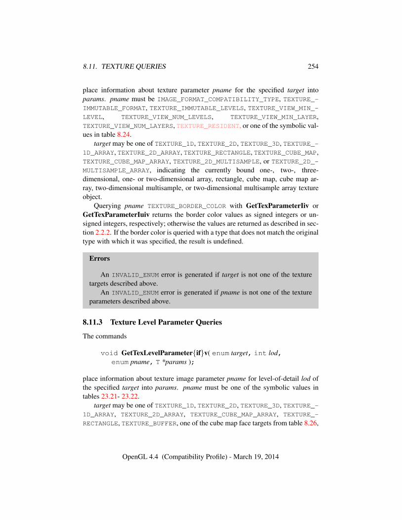
8.11. TEXTURE QUERIES 254
place information about texture parameter pname for the specified target intoparams. pname must be IMAGE_FORMAT_COMPATIBILITY_TYPE, TEXTURE_-IMMUTABLE_FORMAT, TEXTURE_IMMUTABLE_LEVELS, TEXTURE_VIEW_MIN_-LEVEL, TEXTURE_VIEW_NUM_LEVELS, TEXTURE_VIEW_MIN_LAYER,TEXTURE_VIEW_NUM_LAYERS, TEXTURE_RESIDENT, or one of the symbolic val-ues in table 8.24.
target may be one of TEXTURE_1D, TEXTURE_2D, TEXTURE_3D, TEXTURE_-1D_ARRAY, TEXTURE_2D_ARRAY, TEXTURE_RECTANGLE, TEXTURE_CUBE_MAP,TEXTURE_CUBE_MAP_ARRAY, TEXTURE_2D_MULTISAMPLE, or TEXTURE_2D_-MULTISAMPLE_ARRAY, indicating the currently bound one-, two-, three-dimensional, one- or two-dimensional array, rectangle, cube map, cube map ar-ray, two-dimensional multisample, or two-dimensional multisample array textureobject.
Querying pname TEXTURE_BORDER_COLOR with GetTexParameterIiv orGetTexParameterIuiv returns the border color values as signed integers or un-signed integers, respectively; otherwise the values are returned as described in sec-tion 2.2.2. If the border color is queried with a type that does not match the originaltype with which it was specified, the result is undefined.
Errors
An INVALID_ENUM error is generated if target is not one of the texturetargets described above.
An INVALID_ENUM error is generated if pname is not one of the textureparameters described above.
8.11.3 Texture Level Parameter Queries
The commands
void GetTexLevelParameter{if}v( enum target, int lod,enum pname, T *params );
place information about texture image parameter pname for level-of-detail lod ofthe specified target into params. pname must be one of the symbolic values intables 23.21- 23.22.
target may be one of TEXTURE_1D, TEXTURE_2D, TEXTURE_3D, TEXTURE_-1D_ARRAY, TEXTURE_2D_ARRAY, TEXTURE_CUBE_MAP_ARRAY, TEXTURE_-
RECTANGLE, TEXTURE_BUFFER, one of the cube map face targets from table 8.26,
OpenGL 4.4 (Compatibility Profile) - March 19, 2014
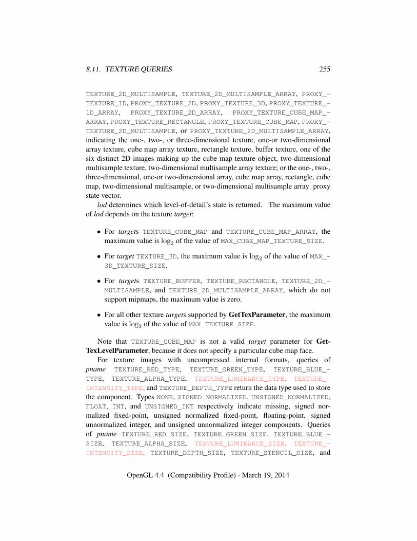
8.11. TEXTURE QUERIES 255
TEXTURE_2D_MULTISAMPLE, TEXTURE_2D_MULTISAMPLE_ARRAY, PROXY_-
TEXTURE_1D, PROXY_TEXTURE_2D, PROXY_TEXTURE_3D, PROXY_TEXTURE_-1D_ARRAY, PROXY_TEXTURE_2D_ARRAY, PROXY_TEXTURE_CUBE_MAP_-
ARRAY, PROXY_TEXTURE_RECTANGLE, PROXY_TEXTURE_CUBE_MAP, PROXY_-TEXTURE_2D_MULTISAMPLE, or PROXY_TEXTURE_2D_MULTISAMPLE_ARRAY,indicating the one-, two-, or three-dimensional texture, one-or two-dimensionalarray texture, cube map array texture, rectangle texture, buffer texture, one of thesix distinct 2D images making up the cube map texture object, two-dimensionalmultisample texture, two-dimensional multisample array texture; or the one-, two-,three-dimensional, one-or two-dimensional array, cube map array, rectangle, cubemap, two-dimensional multisample, or two-dimensional multisample array proxystate vector.
lod determines which level-of-detail’s state is returned. The maximum valueof lod depends on the texture target:
• For targets TEXTURE_CUBE_MAP and TEXTURE_CUBE_MAP_ARRAY, themaximum value is log2 of the value of MAX_CUBE_MAP_TEXTURE_SIZE.
• For target TEXTURE_3D, the maximum value is log2 of the value of MAX_-3D_TEXTURE_SIZE.
• For targets TEXTURE_BUFFER, TEXTURE_RECTANGLE, TEXTURE_2D_-
MULTISAMPLE, and TEXTURE_2D_MULTISAMPLE_ARRAY, which do notsupport mipmaps, the maximum value is zero.
• For all other texture targets supported by GetTexParameter, the maximumvalue is log2 of the value of MAX_TEXTURE_SIZE.
Note that TEXTURE_CUBE_MAP is not a valid target parameter for Get-TexLevelParameter, because it does not specify a particular cube map face.
For texture images with uncompressed internal formats, queries ofpname TEXTURE_RED_TYPE, TEXTURE_GREEN_TYPE, TEXTURE_BLUE_-
TYPE, TEXTURE_ALPHA_TYPE, TEXTURE_LUMINANCE_TYPE, TEXTURE_-
INTENSITY_TYPE, and TEXTURE_DEPTH_TYPE return the data type used to storethe component. Types NONE, SIGNED_NORMALIZED, UNSIGNED_NORMALIZED,FLOAT, INT, and UNSIGNED_INT respectively indicate missing, signed nor-malized fixed-point, unsigned normalized fixed-point, floating-point, signedunnormalized integer, and unsigned unnormalized integer components. Queriesof pname TEXTURE_RED_SIZE, TEXTURE_GREEN_SIZE, TEXTURE_BLUE_-
SIZE, TEXTURE_ALPHA_SIZE, TEXTURE_LUMINANCE_SIZE, TEXTURE_-
INTENSITY_SIZE, TEXTURE_DEPTH_SIZE, TEXTURE_STENCIL_SIZE, and
OpenGL 4.4 (Compatibility Profile) - March 19, 2014
8.11. TEXTURE QUERIES 256
TEXTURE_SHARED_SIZE return the actual resolutions of the stored image arraycomponents, not the resolutions specified when the image array was defined.
For texture images with compressed internal formats, the types returned spec-ify how components are interpreted after decompression, while the resolutions re-turned specify the component resolution of an uncompressed internal format thatproduces an image of roughly the same quality as the compressed image in ques-tion. Since the quality of the implementation’s compression algorithm is likelydata-dependent, the returned component sizes should be treated only as rough ap-proximations.
Querying pname TEXTURE_COMPRESSED_IMAGE_SIZE returns the size (inubytes) of the compressed texture image that would be returned by GetCom-pressedTexImage (section 8.11). target must be a compressed texture target.
Queries of pname TEXTURE_SAMPLES and TEXTURE_FIXED_SAMPLE_-
LOCATIONS on multisample textures return the number of samples and whethertexture sample fixed locations are enabled respectively. For non-multisampletextures, the default values in tables 23.21- 23.22 are returned.
Queries of pname TEXTURE_BORDER, TEXTURE_INTERNAL_-
FORMAT, TEXTURE_WIDTH, TEXTURE_HEIGHT, and TEXTURE_DEPTH return theborder width, internal format, width, height, and depth, respectively, as specifiedwhen the image array was created. The internal format of the image array may alsobe queried as TEXTURE_COMPONENTS for compatibility with GL version 1.0.
Errors
An INVALID_ENUM error is generated if target is not one of the texturetargets described above.
An INVALID_ENUM error is generated if pname is not one of the symbolicvalues in tables 23.21- 23.22.
An INVALID_VALUE error is generated if lod is negative or larger than themaximum allowable level-of-detail for target, as described above.
An INVALID_OPERATION error is generated if pname is TEXTURE_-
COMPRESSED_IMAGE_SIZE and target is a proxy target, or target has an un-compressed internal format.
8.11.4 Texture Image Queries
The command
void GetTexImage( enum tex, int lod, enum format,enum type, void *img );
OpenGL 4.4 (Compatibility Profile) - March 19, 2014

8.11. TEXTURE QUERIES 257
is used to obtain texture images. It is somewhat different from the other Get*commands; tex is a symbolic value indicating which texture (or texture face inthe case of a cube map texture target name) is to be obtained. TEXTURE_-
1D, TEXTURE_2D, TEXTURE_3D, TEXTURE_1D_ARRAY, TEXTURE_2D_ARRAY,TEXTURE_CUBE_MAP_ARRAY, and TEXTURE_RECTANGLE indicate a one-, two-,or three-dimensional, one- or two-dimensional array, cube map array, or rectangletexture respectively. If tex is one of the targets from table 8.26, it indicates thecorresponding face of a cube map texture. lod is a level-of-detail number, formatis a pixel format from table 8.8, type is a pixel type from table 8.7.
GetTexImage obtains component groups from a texture image with the indi-cated level-of-detail. If format is a color format then the components are assignedamong R, G, B, and A according to table 8.25, starting with the first group inthe first row, and continuing by obtaining groups in order from each row and pro-ceeding from the first row to the last, and from the first image to the last for three-dimensional textures. One- and two-dimensional array and cube map array texturesare treated as two-, three-, and three-dimensional images, respectively, where thelayers are treated as rows or images. If format is DEPTH_COMPONENT, DEPTH_-STENCIL, or STENCIL_INDEX, then each depth component and/or stencil index isassigned with the same ordering of rows and images.
These groups are then packed and placed in client or pixel buffer object mem-ory. If a pixel pack buffer is bound (as indicated by a non-zero value of PIXEL_-PACK_BUFFER_BINDING), img is an offset into the pixel pack buffer; otherwise,img is a pointer to client memory. No pixel transfer operations are performed onthis image, but pixel storage modes that are applicable to ReadPixels are applied,as described in table 18.1 and section 18.2.9.
For three-dimensional, two-dimensional array, and cube map array textures,pixel storage operations are applied as if the image were two-dimensional, exceptthat the additional pixel storage state values PACK_IMAGE_HEIGHT and PACK_-
SKIP_IMAGES are applied. The correspondence of texels to memory locations isas defined for TexImage3D in section 8.5.
The row length, number of rows, image depth, and number of images are de-termined by the size of the texture image (including any borders).
Errors
An INVALID_VALUE error is generated if lod is negative or larger than themaximum allowable level.
An INVALID_ENUM error is generated if format is COLOR_INDEX.An INVALID_VALUE error is generated if lod is non-zero and tex is
TEXTURE_RECTANGLE.
OpenGL 4.4 (Compatibility Profile) - March 19, 2014
8.11. TEXTURE QUERIES 258
An INVALID_OPERATION error is generated if any of the following mis-matches between format and the internal format of the texture image exist:• format is a color format (one of the formats in table 8.8 whose target is
the color buffer) and the base internal format of the texture image is nota color format.
• format is DEPTH_COMPONENT and the base internal format is notDEPTH_COMPONENT or DEPTH_STENCIL.
• format is DEPTH_STENCIL and the base internal format is not DEPTH_-STENCIL.
• format is STENCIL_INDEX and the base internal format is notSTENCIL_INDEX or DEPTH_STENCIL.
• format is one of the integer formats in table 8.8 and the internal formatof the texture image is not integer, or format is not one of the integerformats in table 8.8 and the internal format is integer.
An INVALID_OPERATION error is generated if a pixel pack buffer objectis bound and packing the texture image into the buffer’s memory would exceedthe size of the buffer.
An INVALID_OPERATION error is generated if a pixel pack buffer ob-ject is bound and img is not evenly divisible by the number of basic machineunits needed to store in memory the GL data type corresponding to type (seetable 8.7).
The command
void GetCompressedTexImage( enum target, int lod,void *img );
is used to obtain texture images stored in compressed form. The parameters tar-get, lod, and img are interpreted in the same manner as in GetTexImage. Whencalled, GetCompressedTexImage writes n ubytes of compressed image data tothe pixel pack buffer or client memory pointed to by img, where n is the valueof TEXTURE_COMPRESSED_IMAGE_SIZE for the texture. The compressed imagedata is formatted according to the definition of the texture’s internal format.
All pixel transfer modes are ignored when returning a compressed texture im-age.
By default the pixel storage modes PACK_ROW_LENGTH, PACK_SKIP_ROWS,PACK_SKIP_PIXELS, PACK_IMAGE_HEIGHT and PACK_SKIP_IMAGES are ig-nored for compressed images. To enable PACK_SKIP_PIXELS and PACK_-
OpenGL 4.4 (Compatibility Profile) - March 19, 2014
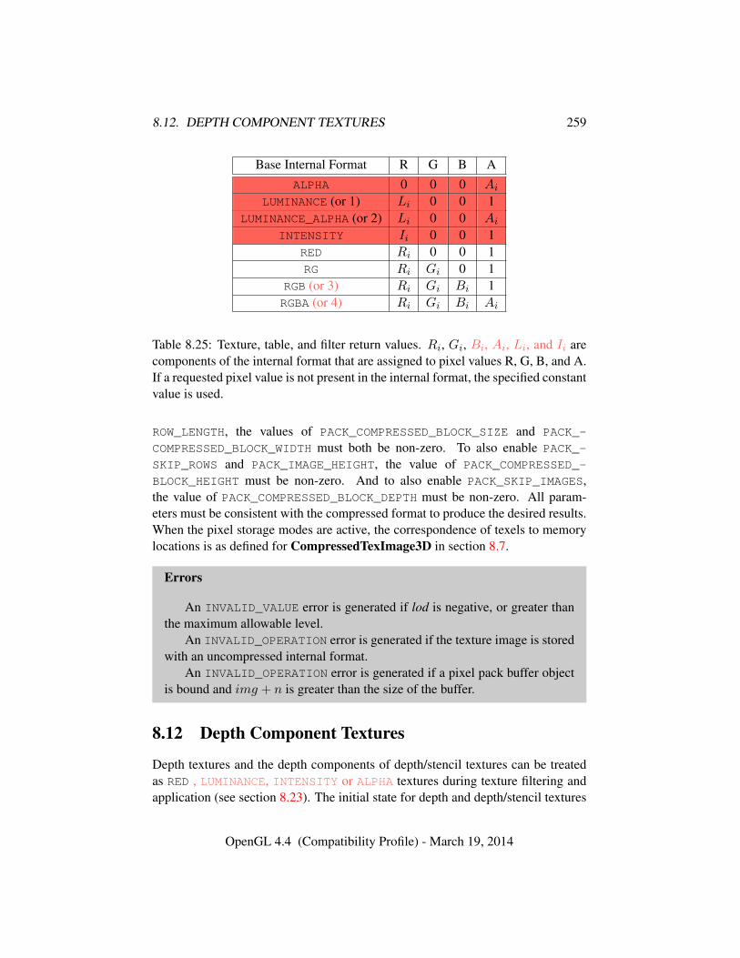
8.12. DEPTH COMPONENT TEXTURES 259
Base Internal Format R G B AALPHA 0 0 0 Ai
LUMINANCE (or 1) Li 0 0 1LUMINANCE_ALPHA (or 2) Li 0 0 Ai
INTENSITY Ii 0 0 1RED Ri 0 0 1RG Ri Gi 0 1
RGB (or 3) Ri Gi Bi 1RGBA (or 4) Ri Gi Bi Ai
Table 8.25: Texture, table, and filter return values. Ri, Gi, Bi, Ai, Li, and Ii arecomponents of the internal format that are assigned to pixel values R, G, B, and A.If a requested pixel value is not present in the internal format, the specified constantvalue is used.
ROW_LENGTH, the values of PACK_COMPRESSED_BLOCK_SIZE and PACK_-
COMPRESSED_BLOCK_WIDTH must both be non-zero. To also enable PACK_-
SKIP_ROWS and PACK_IMAGE_HEIGHT, the value of PACK_COMPRESSED_-
BLOCK_HEIGHT must be non-zero. And to also enable PACK_SKIP_IMAGES,the value of PACK_COMPRESSED_BLOCK_DEPTH must be non-zero. All param-eters must be consistent with the compressed format to produce the desired results.When the pixel storage modes are active, the correspondence of texels to memorylocations is as defined for CompressedTexImage3D in section 8.7.
Errors
An INVALID_VALUE error is generated if lod is negative, or greater thanthe maximum allowable level.
An INVALID_OPERATION error is generated if the texture image is storedwith an uncompressed internal format.
An INVALID_OPERATION error is generated if a pixel pack buffer objectis bound and img + n is greater than the size of the buffer.
8.12 Depth Component Textures
Depth textures and the depth components of depth/stencil textures can be treatedas RED , LUMINANCE, INTENSITY or ALPHA textures during texture filtering andapplication (see section 8.23). The initial state for depth and depth/stencil textures
OpenGL 4.4 (Compatibility Profile) - March 19, 2014
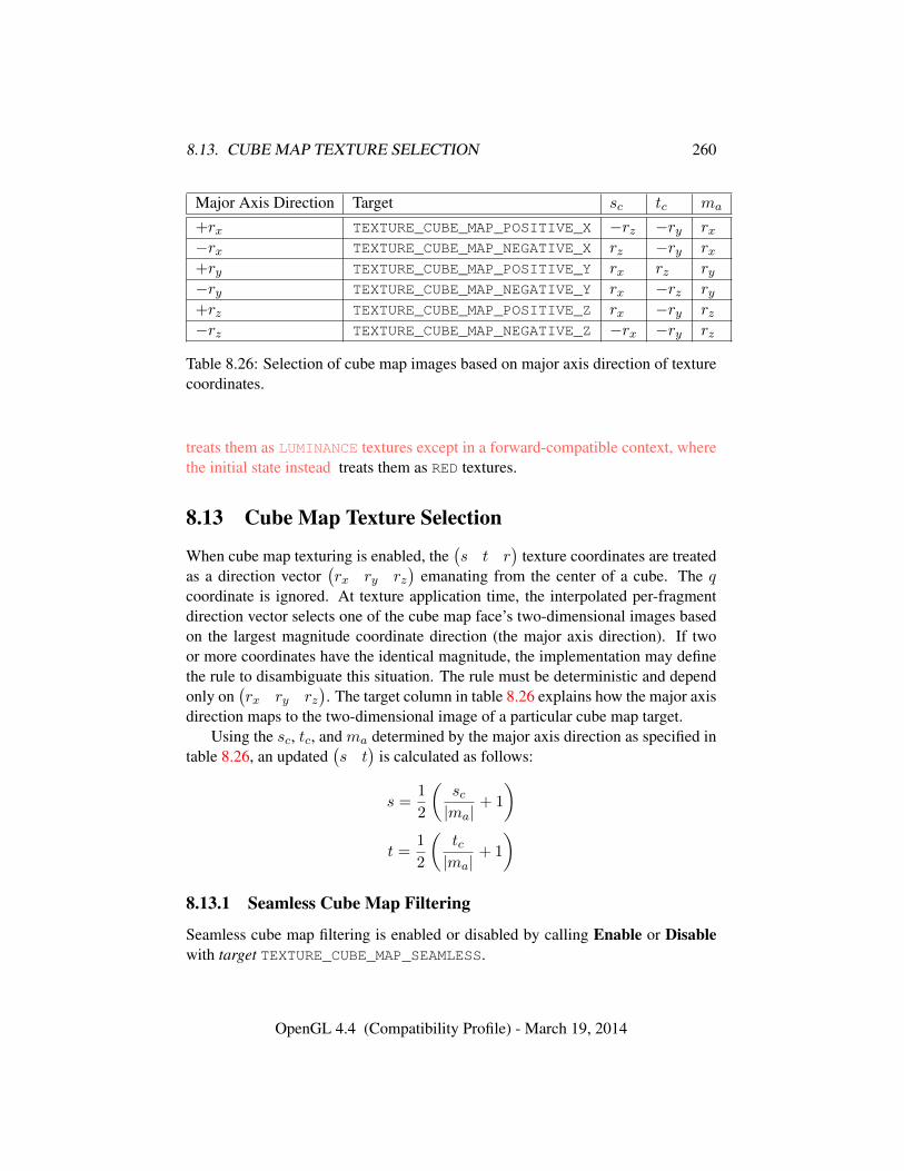
8.13. CUBE MAP TEXTURE SELECTION 260
Major Axis Direction Target sc tc ma
+rx TEXTURE_CUBE_MAP_POSITIVE_X −rz −ry rx−rx TEXTURE_CUBE_MAP_NEGATIVE_X rz −ry rx+ry TEXTURE_CUBE_MAP_POSITIVE_Y rx rz ry−ry TEXTURE_CUBE_MAP_NEGATIVE_Y rx −rz ry+rz TEXTURE_CUBE_MAP_POSITIVE_Z rx −ry rz−rz TEXTURE_CUBE_MAP_NEGATIVE_Z −rx −ry rz
Table 8.26: Selection of cube map images based on major axis direction of texturecoordinates.
treats them as LUMINANCE textures except in a forward-compatible context, wherethe initial state instead treats them as RED textures.
8.13 Cube Map Texture Selection
When cube map texturing is enabled, the(s t r
)texture coordinates are treated
as a direction vector(rx ry rz
)emanating from the center of a cube. The q
coordinate is ignored. At texture application time, the interpolated per-fragmentdirection vector selects one of the cube map face’s two-dimensional images basedon the largest magnitude coordinate direction (the major axis direction). If twoor more coordinates have the identical magnitude, the implementation may definethe rule to disambiguate this situation. The rule must be deterministic and dependonly on
(rx ry rz
). The target column in table 8.26 explains how the major axis
direction maps to the two-dimensional image of a particular cube map target.Using the sc, tc, and ma determined by the major axis direction as specified in
table 8.26, an updated(s t
)is calculated as follows:
s =1
2
(sc|ma|
+ 1
)t =
1
2
(tc|ma|
+ 1
)
8.13.1 Seamless Cube Map Filtering
Seamless cube map filtering is enabled or disabled by calling Enable or Disablewith target TEXTURE_CUBE_MAP_SEAMLESS.
OpenGL 4.4 (Compatibility Profile) - March 19, 2014
8.14. TEXTURE MINIFICATION 261
When seamless cube map filtering is disabled, the new(s t
)is used to find a
texture value in the determined face’s two-dimensional image using the rules givenin sections 8.14 through 8.15.
When seamless cube map filtering is enabled, the rules for texel selection insections 8.14 through 8.15 are modified so that texture wrap modes are ignored.Instead,
• If NEAREST filtering is done within a miplevel, always apply wrap modeCLAMP_TO_EDGE.
• If LINEAR filtering is done within a miplevel, always apply wrap modeCLAMP_TO_BORDER. Then,
– If a texture sample location would lie in the texture border in either uor v, instead select the corresponding texel from the appropriate neigh-boring face.
– If a texture sample location would lie in the texture border in both uand v (in one of the corners of the cube), there is no unique neighbor-ing face from which to extract one texel. The recommended method togenerate this texel is to average the values of the three available sam-ples. However, implementations are free to construct this fourth texelin another way, so long as, when the three available samples have thesame value, this texel also has that value.
The required state is one bit indicating whether seamless cube map filtering isenabled or disabled. Initially, it is disabled.
8.14 Texture Minification
Applying a texture to a primitive implies a mapping from texture image space toframebuffer image space. In general, this mapping involves a reconstruction ofthe sampled texture image, followed by a homogeneous warping implied by themapping to framebuffer space, then a filtering, followed finally by a resamplingof the filtered, warped, reconstructed image before applying it to a fragment. Inthe GL this mapping is approximated by one of two simple filtering schemes. Oneof these schemes is selected based on whether the mapping from texture space toframebuffer space is deemed to magnify or minify the texture image.
OpenGL 4.4 (Compatibility Profile) - March 19, 2014
8.14. TEXTURE MINIFICATION 262
8.14.1 Scale Factor and Level of Detail
The choice is governed by a scale factor ρ(x, y) and the level-of-detail parameterλ(x, y), defined as
λbase(x, y) = log2[ρ(x, y)] (8.4)
λ′(x, y) = λbase(x, y) + clamp(biastexobj + biastexunit + biasshader) (8.5)
λ =
lodmax, λ′ > lodmax
λ′, lodmin ≤ λ′ ≤ lodmax
lodmin, λ′ < lodmin
undefined, lodmin > lodmax
(8.6)
biastexobj is the value of TEXTURE_LOD_BIAS for the bound texture object (asdescribed in section 8.10). biastexunit is the value of TEXTURE_LOD_BIAS forthe current texture unit (as described in section 16.1). biasshader is the value ofthe optional bias parameter in the texture lookup functions available to fragmentshaders. If the texture access is performed in a fragment shader without a providedbias, or outside a fragment shader, then biasshader is zero. The sum of these valuesis clamped to the range [−biasmax, biasmax] where biasmax is the value of theimplementation defined constant MAX_TEXTURE_LOD_BIAS.
Different implementations have chosen to perform clamping on intermediateand final terms in computing λ′ differently. Care should be taken that intermediateterms do not exceed the implementation-dependent range as different results mayotherwise occur.
If λ(x, y) is less than or equal to the constant c (see section 8.15) the texture issaid to be magnified; if it is greater, the texture is minified. Sampling of minifiedtextures is described in the remainder of this section, while sampling of magnifiedtextures is described in section 8.15.
The initial values of lodmin and lodmax are chosen so as to never clamp thenormal range of λ.
Let s(x, y) be the function that associates an s texture coordinate with each setof window coordinates (x, y) that lie within a primitive; define t(x, y) and r(x, y)
OpenGL 4.4 (Compatibility Profile) - March 19, 2014
8.14. TEXTURE MINIFICATION 263
analogously. Let
u(x, y) =
{s(x, y) + δu, rectangle texturewt × s(x, y) + δu, otherwise
v(x, y) =
{t(x, y) + δv, rectangle textureht × t(x, y) + δv, otherwise
w(x, y) = dt × r(x, y) + δw
(8.7)
where wt, ht, and dt are as defined by equation 8.3 with ws, hs, and ds equal tothe width, height, and depth of the image array whose level is levelbase. For a one-dimensional or one-dimensional array texture, define v(x, y) = 0 andw(x, y) = 0;for a two-dimensional, two-dimensional array, rectangle, cube map, or cube maparray texture, define w(x, y) = 0.
(δu, δv, δw) are the texel offsets specified in the OpenGL Shading Languagetexture lookup functions that support offsets. If the texture function used does notsupport offsets, or for fixed-function texture accesses, all three shader offsets aretaken to be zero.
If the value of any non-ignored component of the offset vector operand isoutside implementation-dependent limits, the results of the texture lookup areundefined. For all instructions except textureGather, the limits are the val-ues of MIN_PROGRAM_TEXEL_OFFSET and MAX_PROGRAM_TEXEL_OFFSET. Forthe textureGather instruction, the limits are the values of MIN_PROGRAM_-TEXTURE_GATHER_OFFSET and MAX_PROGRAM_TEXTURE_GATHER_OFFSET.
For a polygon, or for a point sprite with texture coordinate replacement en-abled, ρ is given at a fragment with window coordinates (x, y) by
ρ = max
√(
∂u
∂x
)2
+
(∂v
∂x
)2
+
(∂w
∂x
)2
,
√(∂u
∂y
)2
+
(∂v
∂y
)2
+
(∂w
∂y
)2
(8.8)where ∂u/∂x indicates the derivative of u with respect to window x, and similarlyfor the other derivatives.
For a line, the formula is
ρ =
√(∂u
∂x∆x+
∂u
∂y∆y
)2
+
(∂v
∂x∆x+
∂v
∂y∆y
)2
+
(∂w
∂x∆x+
∂w
∂y∆y
)2/l,
(8.9)
OpenGL 4.4 (Compatibility Profile) - March 19, 2014
8.14. TEXTURE MINIFICATION 264
where ∆x = x2 − x1 and ∆y = y2 − y1 with (x1, y1) and (x2, y2) being thesegment’s window coordinate endpoints and l =
√∆x2 + ∆y2.
For a point, point sprite without texture coordinate replacement enabled, pixelrectangle, or bitmap, ρ = 1.
While it is generally agreed that equations 8.8 and 8.9 give the best results whentexturing, they are often impractical to implement. Therefore, an implementationmay approximate the ideal ρ with a function f(x, y) subject to these conditions:
1. f(x, y) is continuous and monotonically increasing in each of |∂u/∂x|,|∂u/∂y|, |∂v/∂x|, |∂v/∂y|, |∂w/∂x|, and |∂w/∂y|
2. Let
mu = max
{∣∣∣∣∂u∂x∣∣∣∣ , ∣∣∣∣∂u∂y
∣∣∣∣}
mv = max
{∣∣∣∣∂v∂x∣∣∣∣ , ∣∣∣∣∂v∂y
∣∣∣∣}
mw = max
{∣∣∣∣∂w∂x∣∣∣∣ , ∣∣∣∣∂w∂y
∣∣∣∣} .Then max{mu,mv,mw} ≤ f(x, y) ≤ mu +mv +mw.
8.14.2 Coordinate Wrapping and Texel Selection
After generating u(x, y), v(x, y), and w(x, y), they may be clamped and wrappedbefore sampling the texture, depending on the corresponding texture wrap modes.
Let
u′(x, y) =
{clamp(u(x, y), 0, wt), TEXTURE_WRAP_S is CLAMPu(x, y), otherwise
v′(x, y) =
{clamp(v(x, y), 0, ht), TEXTURE_WRAP_T is CLAMPv(x, y), otherwise
w′(x, y) =
{clamp(w(x, y), 0, ht), TEXTURE_WRAP_R is CLAMPw(x, y), otherwise
where clamp(a, b, c) returns b if a < b, c if a > c, and a otherwise.
OpenGL 4.4 (Compatibility Profile) - March 19, 2014
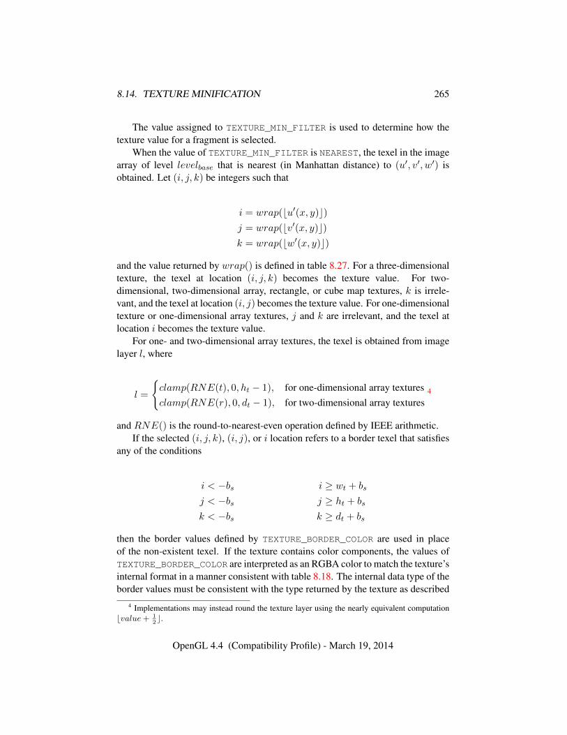
8.14. TEXTURE MINIFICATION 265
The value assigned to TEXTURE_MIN_FILTER is used to determine how thetexture value for a fragment is selected.
When the value of TEXTURE_MIN_FILTER is NEAREST, the texel in the imagearray of level levelbase that is nearest (in Manhattan distance) to (u′, v′, w′) isobtained. Let (i, j, k) be integers such that
i = wrap(bu′(x, y)c)j = wrap(bv′(x, y)c)k = wrap(bw′(x, y)c)
and the value returned by wrap() is defined in table 8.27. For a three-dimensionaltexture, the texel at location (i, j, k) becomes the texture value. For two-dimensional, two-dimensional array, rectangle, or cube map textures, k is irrele-vant, and the texel at location (i, j) becomes the texture value. For one-dimensionaltexture or one-dimensional array textures, j and k are irrelevant, and the texel atlocation i becomes the texture value.
For one- and two-dimensional array textures, the texel is obtained from imagelayer l, where
l =
{clamp(RNE(t), 0, ht − 1), for one-dimensional array texturesclamp(RNE(r), 0, dt − 1), for two-dimensional array textures
4
and RNE() is the round-to-nearest-even operation defined by IEEE arithmetic.If the selected (i, j, k), (i, j), or i location refers to a border texel that satisfies
any of the conditions
i < −bs i ≥ wt + bs
j < −bs j ≥ ht + bs
k < −bs k ≥ dt + bs
then the border values defined by TEXTURE_BORDER_COLOR are used in placeof the non-existent texel. If the texture contains color components, the values ofTEXTURE_BORDER_COLOR are interpreted as an RGBA color to match the texture’sinternal format in a manner consistent with table 8.18. The internal data type of theborder values must be consistent with the type returned by the texture as described
4 Implementations may instead round the texture layer using the nearly equivalent computationbvalue+ 1
2c.
OpenGL 4.4 (Compatibility Profile) - March 19, 2014
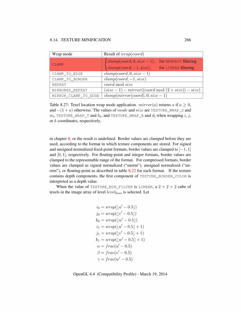
8.14. TEXTURE MINIFICATION 266
Wrap mode Result of wrap(coord)
CLAMP
{clamp(coord, 0, size− 1), for NEAREST filteringclamp(coord,−1, size), for LINEAR filtering
CLAMP_TO_EDGE clamp(coord, 0, size− 1)
CLAMP_TO_BORDER clamp(coord,−1, size)
REPEAT coord mod size
MIRRORED_REPEAT (size− 1)−mirror((coord mod (2× size))− size)MIRROR_CLAMP_TO_EDGE clamp(mirror(coord), 0, size− 1)
Table 8.27: Texel location wrap mode application. mirror(a) returns a if a ≥ 0,and −(1 + a) otherwise. The values of mode and size are TEXTURE_WRAP_S andwt, TEXTURE_WRAP_T and ht, and TEXTURE_WRAP_R and dt when wrapping i, j,or k coordinates, respectively.
in chapter 8, or the result is undefined. Border values are clamped before they areused, according to the format in which texture components are stored. For signedand unsigned normalized fixed-point formats, border values are clamped to [−1, 1]and [0, 1], respectively. For floating-point and integer formats, border values areclamped to the representable range of the format. For compressed formats, bordervalues are clamped as signed normalized (“snorm”), unsigned normalized (“un-orm”), or floating-point as described in table 8.22 for each format. If the texturecontains depth components, the first component of TEXTURE_BORDER_COLOR isinterpreted as a depth value.
When the value of TEXTURE_MIN_FILTER is LINEAR, a 2 × 2 × 2 cube oftexels in the image array of level levelbase is selected. Let
i0 = wrap(bu′ − 0.5c)j0 = wrap(bv′ − 0.5c)k0 = wrap(bw′ − 0.5c)i1 = wrap(bu′ − 0.5c+ 1)
j1 = wrap(bv′ − 0.5c+ 1)
k1 = wrap(bw′ − 0.5c+ 1)
α = frac(u′ − 0.5)
β = frac(v′ − 0.5)
γ = frac(w′ − 0.5)
OpenGL 4.4 (Compatibility Profile) - March 19, 2014
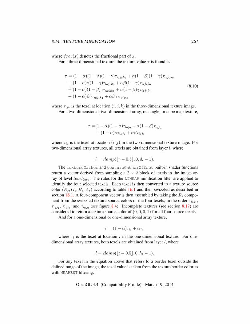
8.14. TEXTURE MINIFICATION 267
where frac(x) denotes the fractional part of x.For a three-dimensional texture, the texture value τ is found as
τ = (1− α)(1− β)(1− γ)τi0j0k0 + α(1− β)(1− γ)τi1j0k0
+ (1− α)β(1− γ)τi0j1k0 + αβ(1− γ)τi1j1k0
+ (1− α)(1− β)γτi0j0k1 + α(1− β)γτi1j0k1
+ (1− α)βγτi0j1k1 + αβγτi1j1k1
(8.10)
where τijk is the texel at location (i, j, k) in the three-dimensional texture image.For a two-dimensional, two-dimensional array, rectangle, or cube map texture,
τ =(1− α)(1− β)τi0j0 + α(1− β)τi1j0
+ (1− α)βτi0j1 + αβτi1j1
where τij is the texel at location (i, j) in the two-dimensional texture image. Fortwo-dimensional array textures, all texels are obtained from layer l, where
l = clamp(br + 0.5c, 0, dt − 1).
The textureGather and textureGatherOffset built-in shader functionsreturn a vector derived from sampling a 2 × 2 block of texels in the image ar-ray of level levelbase. The rules for the LINEAR minification filter are applied toidentify the four selected texels. Each texel is then converted to a texture sourcecolor (Rs, Gs, Bs, As) according to table 16.1 and then swizzled as described insection 16.1. A four-component vector is then assembled by taking the Rs compo-nent from the swizzled texture source colors of the four texels, in the order τi0j1 ,τi1j1 , τi1j0 , and τi0j0 (see figure 8.4). Incomplete textures (see section 8.17) areconsidered to return a texture source color of (0, 0, 0, 1) for all four source texels.
And for a one-dimensional or one-dimensional array texture,
τ = (1− α)τi0 + ατi1
where τi is the texel at location i in the one-dimensional texture. For one-dimensional array textures, both texels are obtained from layer l, where
l = clamp(bt+ 0.5c, 0, ht − 1).
For any texel in the equation above that refers to a border texel outside thedefined range of the image, the texel value is taken from the texture border color aswith NEAREST filtering.
OpenGL 4.4 (Compatibility Profile) - March 19, 2014
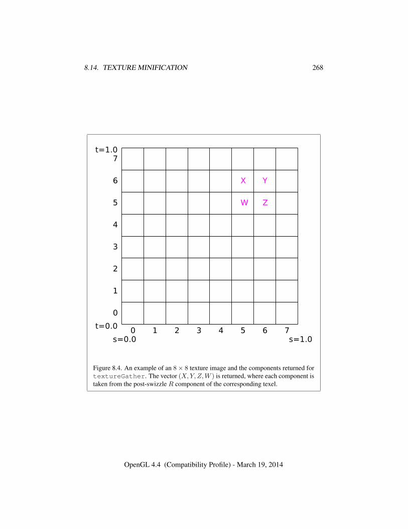
8.14. TEXTURE MINIFICATION 268
Figure 8.4. An example of an 8× 8 texture image and the components returned fortextureGather. The vector (X,Y, Z,W ) is returned, where each component istaken from the post-swizzle R component of the corresponding texel.
OpenGL 4.4 (Compatibility Profile) - March 19, 2014
8.14. TEXTURE MINIFICATION 269
8.14.2.1 Rendering Feedback Loops
If all of the following conditions are satisfied, then the value of the selected τijk,τij , or τi in the above equations is undefined instead of referring to the value of thetexel at location (i, j, k), (i, j), or (i) respectively. This situation is discussed inmore detail in the description of feedback loops in section 9.3.1.
• The current DRAW_FRAMEBUFFER_BINDING names a framebuffer object F.
• The texture is attached to one of the attachment points, A, of framebufferobject F.
• The value of TEXTURE_MIN_FILTER is NEAREST or LINEAR, and the valueof FRAMEBUFFER_ATTACHMENT_TEXTURE_LEVEL for attachment point Ais equal to levelbase
-or-
The value of TEXTURE_MIN_FILTER is NEAREST_MIPMAP_NEAREST,NEAREST_MIPMAP_LINEAR, LINEAR_MIPMAP_NEAREST, or LINEAR_-
MIPMAP_LINEAR, and the value of FRAMEBUFFER_ATTACHMENT_-
TEXTURE_LEVEL for attachment point A is within the inclusive range fromlevelbase to q.
8.14.3 Mipmapping
TEXTURE_MIN_FILTER values NEAREST_MIPMAP_NEAREST, NEAREST_-
MIPMAP_LINEAR, LINEAR_MIPMAP_NEAREST, and LINEAR_MIPMAP_LINEAR
each require the use of a mipmap. Rectangle textures do not support mipmapping(it is an error to specify a minification filter that requires mipmapping). A mipmapis an ordered set of arrays representing the same image; each array has a resolutionlower than the previous one. If the image array of level levelbase (excluding itsborder) has dimensions wt × ht × dt, then there are blog2(maxsize)c + 1 levelsin the mipmap. where
maxsize =
wt, for 1D and 1D array texturesmax(wt, ht), for 2D, 2D array, cube map, and cube map array texturesmax(wt, ht, dt), for 3D textures
Numbering the levels such that level levelbase is the 0th level, the ith array hasdimensions
OpenGL 4.4 (Compatibility Profile) - March 19, 2014
8.14. TEXTURE MINIFICATION 270
max(1,
⌊wt
wd
⌋)×max(1,
⌊hthd
⌋)×max(1,
⌊dtdd
⌋)
where
wd = 2i
hd =
{1, for 1D and 1D array textures2i, otherwise
dd =
{2i, for 3D textures1, otherwise
until the last array is reached with dimension 1× 1× 1.Each array in a mipmap is defined using TexImage3D, TexImage2D, Copy-
TexImage2D, TexImage1D, or CopyTexImage1D or by functions that are de-fined in terms of these functions. The array being set is indicated with the level-of-detail argument level. Level-of-detail numbers proceed from levelbase for theoriginal texel array through the maximum level p, with each unit increase in-dicating an array of half the dimensions of the previous one (rounded down tothe next integer if fractional) as already described. For immutable-format tex-tures, levelbase is clamped to the range [0, levelimmut − 1], levelmax is thenclamped to the range [levelbase, levelimmut−1], and p is one less than levelimmut,where levelimmut is the levels parameter passed to TexStorage* for the textureobject (the value of TEXTURE_IMMUTABLE_LEVELS; see section 8.19). Other-wise p = blog2(maxsize)c + levelbase, and all arrays from levelbase throughq = min{p, levelmax} must be defined, as discussed in section 8.17.
by TexParameter* if either value is negative.The mipmap is used in conjunction with the level of detail to approximate the
application of an appropriately filtered texture to a fragment. Let c be the valueof λ at which the transition from minification to magnification occurs (since thisdiscussion pertains to minification, we are concerned only with values of λ whereλ > c).
For mipmap filters NEAREST_MIPMAP_NEAREST and LINEAR_MIPMAP_-
NEAREST, the dth mipmap array is selected, where
d =
levelbase, λ ≤ 1
2
dlevelbase + λ+ 12e − 1, λ > 1
2 , levelbase + λ ≤ q + 12
5
q, λ > 12 , levelbase + λ > q + 1
2
(8.11)
OpenGL 4.4 (Compatibility Profile) - March 19, 2014
8.14. TEXTURE MINIFICATION 271
The rules for NEAREST or LINEAR filtering are then applied to the selectedarray. Specifically, the coordinate (u, v, w) is computed as in equation 8.7, withws, hs, and ds equal to the width, height, and depth of the image array whose levelis d.
For mipmap filters NEAREST_MIPMAP_LINEAR and LINEAR_MIPMAP_-
LINEAR, the level d1 and d2 mipmap arrays are selected, where
d1 =
{q, levelbase + λ ≥ qblevelbase + λc, otherwise
(8.12)
d2 =
{q, levelbase + λ ≥ qd1 + 1, otherwise
(8.13)
The rules for NEAREST or LINEAR filtering are then applied to each of theselected arrays, yielding two corresponding texture values τ1 and τ2. Specifically,for level d1, the coordinate (u, v, w) is computed as in equation 8.7, with ws, hs,and ds equal to the width, height, and depth of the image array whose level is d1.For level d2 the coordinate (u′, v′, w′) is computed as in equation 8.7, with ws, hs,and ds equal to the width, height, and depth of the image array whose level is d2.
The final texture value is then found as
τ = [1− frac(λ)]τ1 + frac(λ)τ2.
8.14.4 Manual Mipmap Generation
Mipmaps can be generated manually with the command
void GenerateMipmap( enum target );
where target is one of TEXTURE_1D, TEXTURE_2D, TEXTURE_3D, TEXTURE_-1D_ARRAY, TEXTURE_2D_ARRAY, TEXTURE_CUBE_MAP, or TEXTURE_CUBE_-
MAP_ARRAY.Mipmap generation affects the texture image attached to target.If target is TEXTURE_CUBE_MAP or TEXTURE_CUBE_MAP_ARRAY, the texture
bound to target must be cube complete or cube array complete respectively, asdefined in section 8.17.
Mipmap generation replaces texel array levels levelbase + 1 through q witharrays derived from the levelbase array, regardless of their previous contents. All
5 Implementations may instead use the nearly equivalent computation d = blevelbase + λ+ 12c
in this case.
OpenGL 4.4 (Compatibility Profile) - March 19, 2014
8.14. TEXTURE MINIFICATION 272
other mipmap arrays, including the levelbase array, are left unchanged by this com-putation.
The internal formats and border widths of the derived mipmap arrays all matchthose of the levelbase array, and the dimensions of the derived arrays follow therequirements described in section 8.17.
The contents of the derived arrays are computed by repeated, filtered reductionof the levelbase array. For one- and two-dimensional array and cube map array tex-tures, each layer is filtered independently. No particular filter algorithm is required,though a box filter is recommended as the default filter. In some implementations,filter quality may be affected by hints (section 21.5).
Errors
An INVALID_ENUM error is generated if target is not TEXTURE_1D,TEXTURE_2D, TEXTURE_3D, TEXTURE_1D_ARRAY, TEXTURE_2D_ARRAY,TEXTURE_CUBE_MAP, or TEXTURE_CUBE_MAP_ARRAY.
An INVALID_OPERATION error is generated if target is TEXTURE_-
CUBE_MAP or TEXTURE_CUBE_MAP_ARRAY, and the texture bound to targetis not cube complete or cube array complete respectively.
8.14.5 Automatic Mipmap Generation
If the value of texture parameter GENERATE_MIPMAP is TRUE, and a change ismade to the interior or border texels of the levelbase array of a mipmap by oneof the texture image specification operations defined in sections 8.5 through 8.7,then a6 mipmap complete set of mipmap arrays (as defined in section 8.17) willbe computed (if the array being changed is one face of a cube map texture, onlymipmaps for that face will be computed). Array levels levelbase + 1 through pare replaced with arrays derived from the modified levelbase array, as describedabove for Manual Mipmap Generation. All other mipmap arrays, including thelevelbase array, are left unchanged by this computation. For arrays in the rangelevelbase + 1 through q, inclusive, automatic and manual mipmap generation gen-erate the same derived arrays, given identical levelbase arrays.
Automatic mipmap generation is available only for non-proxy texture imagetargets.
6 Automatic mipmap generation is not performed for changes resulting from rendering operationstargeting a texel array bound as a color buffer of a framebuffer object.
OpenGL 4.4 (Compatibility Profile) - March 19, 2014
8.15. TEXTURE MAGNIFICATION 273
8.15 Texture Magnification
When λ indicates magnification, the value assigned to TEXTURE_MAG_FILTER
determines how the texture value is obtained. There are two possible valuesfor TEXTURE_MAG_FILTER: NEAREST and LINEAR. NEAREST behaves exactly asNEAREST for TEXTURE_MIN_FILTER and LINEAR behaves exactly as LINEAR forTEXTURE_MIN_FILTER as described in section 8.14, including the texture coordi-nate wrap modes specified in table 8.27. The level-of-detail levelbase texel array isalways used for magnification.
Implementations may either unconditionally assume c = 0 for the minifica-tion vs. magnification switch-over point, or may choose to make c depend on thecombination of minification and magnification modes as follows: if the magnifica-tion filter is given by LINEAR and the minification filter is given by NEAREST_-
MIPMAP_NEAREST or NEAREST_MIPMAP_LINEAR, then c = 0.5. This is done toensure that a minified texture does not appear sharper than a magnified texture.Otherwise c = 0.
8.16 Combined Depth/Stencil Textures
If the texture image has a base internal format of DEPTH_STENCIL, then the stencilindex texture component is ignored by default. The texture value τ does not includea stencil index component, but includes only the depth component.
In order to access the stencil index texture component the DEPTH_STENCIL_-TEXTURE_MODE texture parameter should be set to STENCIL_INDEX. When thismode is set the depth component is ignored and the texture value includes only thestencil index component. The stencil index value is treated as an unsigned inte-ger texture and returns an unsigned integer value when sampled. When samplingthe stencil index only NEAREST filtering is supported. The DEPTH_STENCIL_-
TEXTURE_MODE is ignored for non depth/stencil textures.
8.17 Texture Completeness
A texture is said to be complete if all the image arrays and texture parametersrequired to utilize the texture for texture application are consistently defined. Thedefinition of completeness varies depending on texture dimensionality and type.
For one-, two-, and three-dimensional and one-and two-dimensional array tex-tures, a texture is mipmap complete if all of the following conditions hold true:
• The set of mipmap arrays levelbase through q (where q is defined in sec-tion 8.14.3) were each specified with the same internal format.
OpenGL 4.4 (Compatibility Profile) - March 19, 2014
8.17. TEXTURE COMPLETENESS 274
• The border widths of each array are the same.
• The dimensions of the arrays follow the sequence described in section 8.14.3.
• levelbase ≤ levelmax
Array levels k where k < levelbase or k > q are insignificant to the definition ofcompleteness.
A cube map texture is mipmap complete if each of the six texture images,considered individually, is mipmap complete. Additionally, a cube map texture iscube complete if the following conditions all hold true:
• The levelbase arrays of each of the six texture images making up the cubemap have identical, positive, and square dimensions.
• The levelbase arrays were each specified with the same internal format.
• The levelbase arrays each have the same border width.
A cube map array texture is cube array complete if it is complete when treatedas a two-dimensional array and cube complete for every cube map slice within thearray texture.
Using the preceding definitions, a texture is complete unless any of the follow-ing conditions hold true:
• Any dimension of the levelbase array is not positive. For a rectangle or mul-tisample texture, levelbase is always zero.
• The texture is a cube map texture, and is not cube complete.
• The texture is a cube map array texture, and is not cube array complete.
• The minification filter requires a mipmap (is neither NEAREST nor LINEAR),and the texture is not mipmap complete.
• Any of
– The internal format of the texture is integer (see tables 8.19- 8.20).
– The internal format is STENCIL_INDEX.
– The internal format is DEPTH_STENCIL, and the value of DEPTH_-STENCIL_TEXTURE_MODE for the texture is STENCIL_INDEX.
and either the and either the magnification filter is not NEAREST, or the mini-fication filter is neither NEAREST nor NEAREST_MIPMAP_NEAREST.
OpenGL 4.4 (Compatibility Profile) - March 19, 2014
8.17. TEXTURE COMPLETENESS 275
• The internal format of the texture is DEPTH_STENCIL, the DEPTH_-
STENCIL_TEXTURE_MODE for the texture is STENCIL_INDEX and eitherthe magnification filter or the minification filter is not NEAREST.
8.17.1 Effects of Sampler Objects on Texture Completeness
If a sampler object and a texture object are simultaneously bound to the same tex-ture unit, then the sampling state for that unit is taken from the sampler object (seesection 8.2). This can have an effect on the effective completeness of the texture. Inparticular, if the texture is not mipmap complete and the sampler object specifies aTEXTURE_MIN_FILTER requiring mipmaps, the texture will be considered incom-plete for the purposes of that texture unit. However, if the sampler object does notrequire mipmaps, the texture object will be considered complete. This means thata texture can be considered both complete and incomplete simultaneously if it isbound to two or more texture units along with sampler objects with different states.
8.17.2 Effects of Completeness on Texture Application
Texture lookup and texture fetch operations performed in shaders are affectedby completeness of the texture being sampled as described in sections 11.1.3.5and 15.2.1.
For fixed-function texture access, if texturing is enabled for a texture unit at thetime a primitive is rasterized, and if the texture image bound to the enabled texturetarget is not complete, then it is as if texture mapping were disabled for that textureunit.
8.17.3 Effects of Completeness on Texture Image Specification
The implementation-dependent maximum sizes for texture image arrays dependon the texture level. In particular, an implementation may allow a texture imagearray of level one or greater to be created only if a mipmap complete set of imagearrays consistent with the requested array can be supported where the values ofTEXTURE_BASE_LEVEL and TEXTURE_MAX_LEVEL are 0 and 1000 respectively.As a result, implementations may permit a texture image array at level zero that willnever be mipmap complete and can only be used with non-mipmapped minificationfilters.
OpenGL 4.4 (Compatibility Profile) - March 19, 2014
8.18. TEXTURE VIEWS 276
8.18 Texture Views
A texture can be created which references the data store of another texture andinterprets the data with a different format, and/or selects a subset of the levelsand/or layers of the other texture. The data store for such a texture is shared withthe data store of the original texture. Updating the shared data store using theoriginal texture affects texture values read using the new texture, and vice versa. Atexture data store remains in existence until all textures that reference it are deleted.
The command
void TextureView( uint texture, enum target,uint origtexture, enum internalformat, uint minlevel,uint numlevels, uint minlayer, uint numlayers );
initializes the texture named texture to the target specified by target. texture’s datastore is inherited from the texture named origtexture, but elements of the data storeare interpreted according to the internal format specified by internalformat. Ad-ditionally, if origtexture is an array or has multiple mipmap levels, the parametersminlayer, numlayers, minlevel, and numlevels control which of those slices andlevels are considered part of the texture.
The minlevel and minlayer parameters are relative to the view of origtexture. Ifnumlayers or numlevels extend beyond origtexture, they are clamped to the maxi-mum extent of the original texture.
If the command is successful, the texture parameters in texture are updated asfollows:
• TEXTURE_IMMUTABLE_FORMAT is set to TRUE.
• TEXTURE_IMMUTABLE_LEVELS is set to the value of TEXTURE_-
IMMUTABLE_LEVELS for origtexture.
• TEXTURE_VIEW_MIN_LEVEL is set to minlevel plus the value ofTEXTURE_VIEW_MIN_LEVEL for origtexture.
• TEXTURE_VIEW_MIN_LAYER is set to minlayer plus the value ofTEXTURE_VIEW_MIN_LAYER for origtexture.
• TEXTURE_VIEW_NUM_LEVELS is set to the lesser of numlevels and the valueof TEXTURE_VIEW_NUM_LEVELS for origtexture minus minlevels.
• TEXTURE_VIEW_NUM_LAYERS is set to the lesser of numlayers and the valueof TEXTURE_VIEW_NUM_LAYERS for origtexture minus minlayer.
OpenGL 4.4 (Compatibility Profile) - March 19, 2014
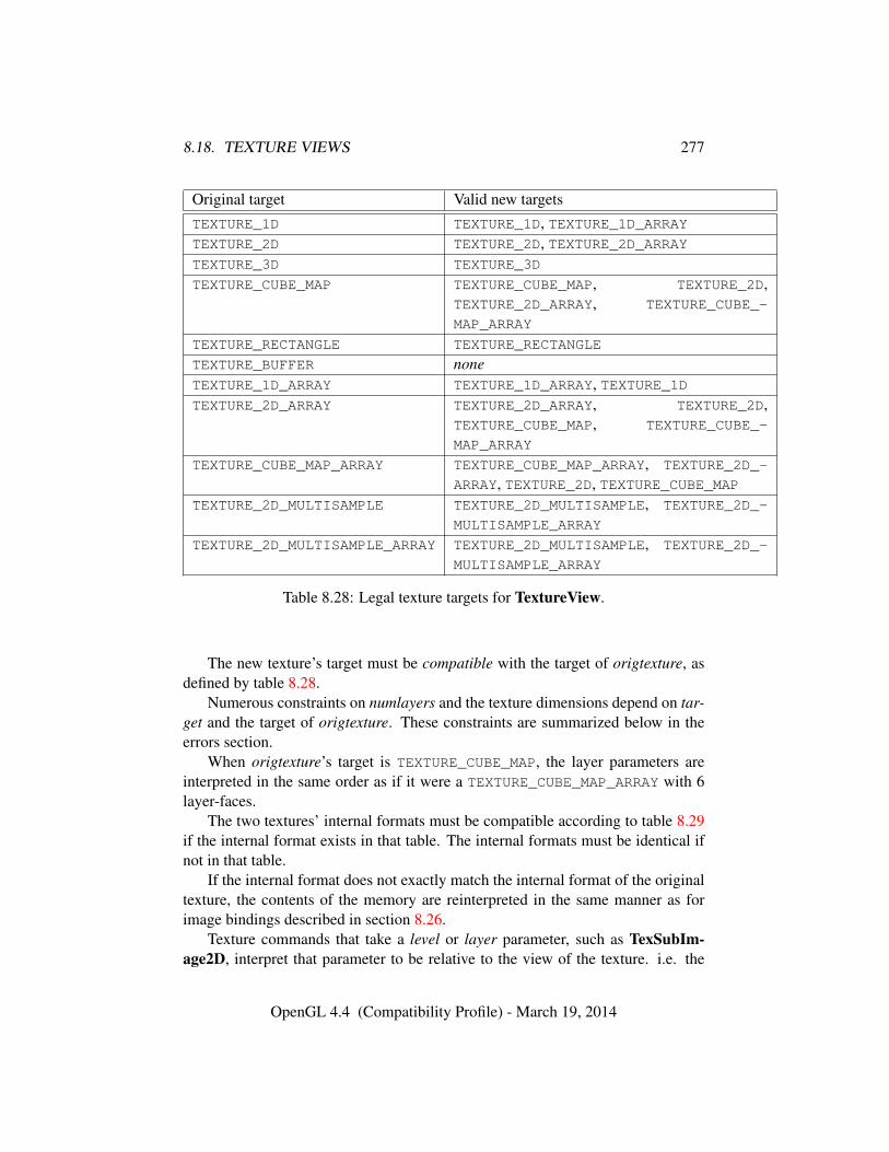
8.18. TEXTURE VIEWS 277
Original target Valid new targetsTEXTURE_1D TEXTURE_1D, TEXTURE_1D_ARRAYTEXTURE_2D TEXTURE_2D, TEXTURE_2D_ARRAYTEXTURE_3D TEXTURE_3D
TEXTURE_CUBE_MAP TEXTURE_CUBE_MAP, TEXTURE_2D,TEXTURE_2D_ARRAY, TEXTURE_CUBE_-
MAP_ARRAY
TEXTURE_RECTANGLE TEXTURE_RECTANGLE
TEXTURE_BUFFER noneTEXTURE_1D_ARRAY TEXTURE_1D_ARRAY, TEXTURE_1DTEXTURE_2D_ARRAY TEXTURE_2D_ARRAY, TEXTURE_2D,
TEXTURE_CUBE_MAP, TEXTURE_CUBE_-
MAP_ARRAY
TEXTURE_CUBE_MAP_ARRAY TEXTURE_CUBE_MAP_ARRAY, TEXTURE_2D_-
ARRAY, TEXTURE_2D, TEXTURE_CUBE_MAPTEXTURE_2D_MULTISAMPLE TEXTURE_2D_MULTISAMPLE, TEXTURE_2D_-
MULTISAMPLE_ARRAY
TEXTURE_2D_MULTISAMPLE_ARRAY TEXTURE_2D_MULTISAMPLE, TEXTURE_2D_-
MULTISAMPLE_ARRAY
Table 8.28: Legal texture targets for TextureView.
The new texture’s target must be compatible with the target of origtexture, asdefined by table 8.28.
Numerous constraints on numlayers and the texture dimensions depend on tar-get and the target of origtexture. These constraints are summarized below in theerrors section.
When origtexture’s target is TEXTURE_CUBE_MAP, the layer parameters areinterpreted in the same order as if it were a TEXTURE_CUBE_MAP_ARRAY with 6layer-faces.
The two textures’ internal formats must be compatible according to table 8.29if the internal format exists in that table. The internal formats must be identical ifnot in that table.
If the internal format does not exactly match the internal format of the originaltexture, the contents of the memory are reinterpreted in the same manner as forimage bindings described in section 8.26.
Texture commands that take a level or layer parameter, such as TexSubIm-age2D, interpret that parameter to be relative to the view of the texture. i.e. the
OpenGL 4.4 (Compatibility Profile) - March 19, 2014
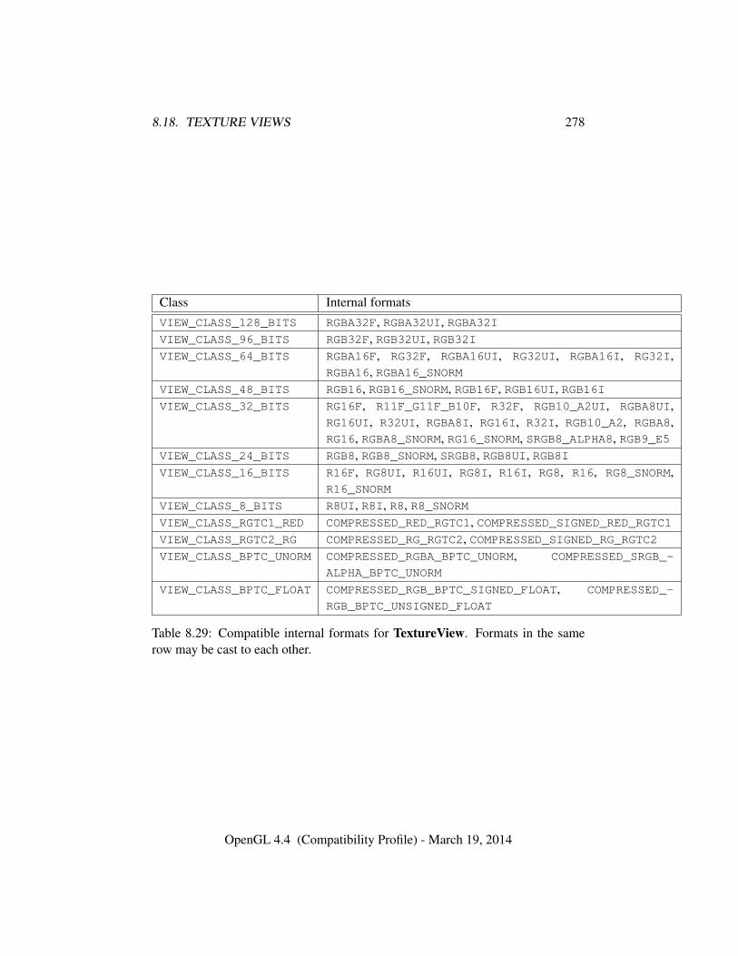
8.18. TEXTURE VIEWS 278
Class Internal formatsVIEW_CLASS_128_BITS RGBA32F, RGBA32UI, RGBA32IVIEW_CLASS_96_BITS RGB32F, RGB32UI, RGB32IVIEW_CLASS_64_BITS RGBA16F, RG32F, RGBA16UI, RG32UI, RGBA16I, RG32I,
RGBA16, RGBA16_SNORMVIEW_CLASS_48_BITS RGB16, RGB16_SNORM, RGB16F, RGB16UI, RGB16IVIEW_CLASS_32_BITS RG16F, R11F_G11F_B10F, R32F, RGB10_A2UI, RGBA8UI,
RG16UI, R32UI, RGBA8I, RG16I, R32I, RGB10_A2, RGBA8,RG16, RGBA8_SNORM, RG16_SNORM, SRGB8_ALPHA8, RGB9_E5
VIEW_CLASS_24_BITS RGB8, RGB8_SNORM, SRGB8, RGB8UI, RGB8IVIEW_CLASS_16_BITS R16F, RG8UI, R16UI, RG8I, R16I, RG8, R16, RG8_SNORM,
R16_SNORM
VIEW_CLASS_8_BITS R8UI, R8I, R8, R8_SNORMVIEW_CLASS_RGTC1_RED COMPRESSED_RED_RGTC1, COMPRESSED_SIGNED_RED_RGTC1VIEW_CLASS_RGTC2_RG COMPRESSED_RG_RGTC2, COMPRESSED_SIGNED_RG_RGTC2VIEW_CLASS_BPTC_UNORM COMPRESSED_RGBA_BPTC_UNORM, COMPRESSED_SRGB_-
ALPHA_BPTC_UNORM
VIEW_CLASS_BPTC_FLOAT COMPRESSED_RGB_BPTC_SIGNED_FLOAT, COMPRESSED_-
RGB_BPTC_UNSIGNED_FLOAT
Table 8.29: Compatible internal formats for TextureView. Formats in the samerow may be cast to each other.
OpenGL 4.4 (Compatibility Profile) - March 19, 2014

8.18. TEXTURE VIEWS 279
mipmap level of the data store that would be updated via TexSubImage2D wouldbe the sum of level and the value of TEXTURE_VIEW_MIN_LEVEL.
Errors
An INVALID_VALUE error is generated if texture is zero.An INVALID_OPERATION error is generated if texture is not a valid name
returned by GenTextures, or if texture has already been bound and given atarget.
An INVALID_VALUE error is generated if origtexture is not the name of atexture.
An INVALID_OPERATION error is generated if the value of TEXTURE_-IMMUTABLE_FORMAT for origtexture is not TRUE.
An INVALID_OPERATION error is generated if target is not compatiblewith the target of origtexture, as defined by table 8.28.
An INVALID_OPERATION error is generated if the internal format of orig-texture exists in table 8.29 and is not compatible with internalformat, as de-scribed in that table.
An INVALID_OPERATION error is generated if the internal format of orig-texture does not exist in table 8.29, and is not identical to internalformat.
An INVALID_VALUE error is generated if minlevel or minlayer are largerthan the greatest level or layer, respectively, of origtexture.
An INVALID_VALUE error is generated if target is TEXTURE_CUBE_MAPand the clamped numlayers is not 6.
An INVALID_VALUE error is generated if target is TEXTURE_CUBE_-
MAP_ARRAY and the clamped numlayers is not a multiple of 6. In this casenumlayers counts layer-faces rather than layers.
An INVALID_VALUE error is generated if target is TEXTURE_1D,TEXTURE_2D, TEXTURE_3D, TEXTURE_RECTANGLE, or TEXTURE_2D_-
MULTISAMPLE and numlayers does not equal 1.An INVALID_OPERATION error is generated if target is TEXTURE_-
CUBE_MAP or TEXTURE_CUBE_MAP_ARRAY, and the width and height of orig-texture’s levels are not equal.
An INVALID_OPERATION error is generated if any dimension of origtex-ture is larger than the maximum supported corresponding dimension of thenew target. For example, if origtexture has a TEXTURE_2D_ARRAY target andtarget is TEXTURE_CUBE_MAP, its width must be no greater than the value ofMAX_CUBE_MAP_TEXTURE_SIZE.
OpenGL 4.4 (Compatibility Profile) - March 19, 2014
8.19. IMMUTABLE-FORMAT TEXTURE IMAGES 280
8.19 Immutable-Format Texture Images
An alternative set of commands is provided for specifying the properties of alllevels of a texture at once. Once a texture is specified with such a command, theformat and dimensions of all levels becomes immutable, unless it is a proxy texture(since otherwise it would no longer be possible to use the proxy). The contents ofthe images and the parameters can still be modified. Such a texture is referredto as an immutable-format texture. The immutability status of a texture can bedetermined by calling GetTexParameter with pname TEXTURE_IMMUTABLE_-
FORMAT.Each of the commands below is described by pseudocode which indicates the
effect on the dimensions and format of the texture. For each command the follow-ing apply in addition to the pseudocode:
• If executing the pseudocode would result in any other error, the error is gen-erated and the command will have no effect.
• Any existing levels that are not replaced are reset to their initial state.
• The pixel unpack buffer should be considered to be zero; i.e., the imagecontents are unspecified.
• Since no pixel data are provided, the format and type values used in thepseudocode are irrelevant; they can be considered to be any values that arelegal to use with internalformat.
• If the command is successful, TEXTURE_IMMUTABLE_FORMAT becomesTRUE. TEXTURE_IMMUTABLE_LEVELS and TEXTURE_VIEW_NUM_LEVELSbecome levels. If the texture target is TEXTURE_1D_ARRAY thenTEXTURE_VIEW_NUM_LAYERS becomes height. If the texture target isTEXTURE_2D_ARRAY, TEXTURE_CUBE_MAP_ARRAY, or TEXTURE_2D_-
MULTISAMPLE_ARRAY then TEXTURE_VIEW_NUM_LAYERS becomes depth.If the texture target is TEXTURE_CUBE_MAP, then TEXTURE_VIEW_NUM_-
LAYERS becomes 6. For any other texture target, TEXTURE_VIEW_NUM_-LAYERS becomes 1.
For each command, the following errors are generated in addition to the errorsdescribed specific to that command:
Errors
An INVALID_OPERATION error is generated if zero is bound to target.An INVALID_VALUE error is generated if width, height, depth or levels
OpenGL 4.4 (Compatibility Profile) - March 19, 2014
8.19. IMMUTABLE-FORMAT TEXTURE IMAGES 281
are less than 1.An INVALID_ENUM error is generated if internalformat is one of the un-
sized base internal formats listed in table 8.18.
The command
void TexStorage1D( enum target, sizei levels,enum internalformat, sizei width );
specifies all the levels of a one-dimensional texture (or proxy) at the same time. Itis described by the pseudocode below:
for (i = 0; i < levels; i++) {TexImage1D(target, i, internalformat, width, 0,
format, type, NULL);width = max(1,
⌊width
2
⌋);
}
Errors
An INVALID_ENUM error is generated if target is not TEXTURE_1D orPROXY_TEXTURE_1D.
An INVALID_OPERATION error is generated if levels is greater thanblog2(width)c+ 1.
An INVALID_VALUE error is generated if width is negative.
The command
void TexStorage2D( enum target, sizei levels,enum internalformat, sizei width, sizei height );
specifies all the levels of a two-dimensional, cube map, one-dimension array orrectangle texture (or proxy) at the same time. The pseudocode depends on target:
targets TEXTURE_2D, PROXY_TEXTURE_2D, TEXTURE_RECTANGLE, PROXY_-
TEXTURE_RECTANGLE, or PROXY_TEXTURE_CUBE_MAP:
for (i = 0; i < levels; i++) {TexImage2D(target, i, internalformat, width, height, 0,
format, type, NULL);width = max(1,
⌊width
2
⌋);
height = max(1,⌊height
2
⌋);
}
OpenGL 4.4 (Compatibility Profile) - March 19, 2014
8.19. IMMUTABLE-FORMAT TEXTURE IMAGES 282
target TEXTURE_CUBE_MAP:
for (i = 0; i < levels; i++) {for face in (+X, -X, +Y, -Y, +Z, -Z) {
TexImage2D(face, i, internalformat, width, height, 0,format, type, NULL);
}width = max(1,
⌊width
2
⌋);
height = max(1,⌊height
2
⌋);
}
targets TEXTURE_1D_ARRAY or PROXY_TEXTURE_1D_ARRAY:
for (i = 0; i < levels; i++) {TexImage2D(target, i, internalformat, width, height, 0,
format, type, NULL);width = max(1,
⌊width
2
⌋);
}
Errors
An INVALID_ENUM error is generated if target is not one of those listedabove,
An INVALID_OPERATION error is generated if any of the following con-ditions hold:• target is TEXTURE_1D_ARRAY or PROXY_TEXTURE_1D_ARRAY, and
levels is greater than blog2(width)c+ 1
• target is not TEXTURE_1D_ARRAY or PROXY_TEXTURE_1D_ARRAY,and levels is greater than blog2(max(width, height))c+ 1
An INVALID_VALUE error is generated if width or height is negative.
The command
void TexStorage3D( enum target, sizei levels,enum internalformat, sizei width, sizei height,sizei depth );
specifies all the levels of a three-dimensional, two-dimensional array texture, orcube map array texture (or proxy). The pseudocode depends on the target:
targets TEXTURE_3D or PROXY_TEXTURE_3D:
OpenGL 4.4 (Compatibility Profile) - March 19, 2014
8.19. IMMUTABLE-FORMAT TEXTURE IMAGES 283
for (i = 0; i < levels; i++) {TexImage3D(target, i, internalformat, width, height, depth, 0,
format, type, NULL);width = max(1,
⌊width
2
⌋);
height = max(1,⌊height
2
⌋);
depth = max(1,⌊depth
2
⌋);
}
targets TEXTURE_2D_ARRAY, PROXY_TEXTURE_2D_ARRAY, TEXTURE_CUBE_-MAP_ARRAY or PROXY_TEXTURE_CUBE_MAP_ARRAY:
for (i = 0; i < levels; i++) {TexImage3D(target, i, internalformat, width, height, depth, 0,
format, type, NULL);width = max(1,
⌊width
2
⌋);
height = max(1,⌊height
2
⌋);
}
Errors
An INVALID_ENUM error is generated if target is not one of those listedabove,
An INVALID_OPERATION error is generated if any of the following con-ditions hold:• target is TEXTURE_3D or PROXY_TEXTURE_3D and levels is greater
than blog2(max(width, height, depth)))c+ 1
• target is TEXTURE_2D_ARRAY, PROXY_TEXTURE_2D_ARRAY,TEXTURE_CUBE_MAP_ARRAY or PROXY_TEXTURE_CUBE_MAP_-
ARRAY and levels is greater than blog2(max(width, height))c+ 1An INVALID_VALUE error is generated if width, height, or depth is nega-
tive.
The command
void TexStorage2DMultisample( enum target, sizei samples,enum internalformat, sizei width, sizei height,boolean fixedsamplelocations );
specifies a two-dimensional multisample texture (or proxy). target mustbe TEXTURE_2D_MULTISAMPLE or PROXY_TEXTURE_2D_MULTISAMPLE. The
OpenGL 4.4 (Compatibility Profile) - March 19, 2014
8.19. IMMUTABLE-FORMAT TEXTURE IMAGES 284
pseudo-code is equivalent to calling TexImage2DMultisample with the equiva-lently named parameters set to the same values.
Errors
An INVALID_ENUM error is generated if target is not TEXTURE_2D_-MULTISAMPLE or PROXY_TEXTURE_2D_MULTISAMPLE.
An INVALID_VALUE error is generated if width or height is negative.
The command
void TexStorage3DMultisample( enum target, sizei samples,enum internalformat, sizei width, sizei height,sizei depth, boolean fixedsamplelocations );
specifies a two-dimensional multisample array texture (or proxy). tar-get must be TEXTURE_2D_MULTISAMPLE_ARRAY or PROXY_TEXTURE_2D_-
MULTISAMPLE_ARRAY. The pseudo-code is equivalent to calling TexIm-age3DMultisample with the equivalently named parameters set to the same values.
Errors
An INVALID_ENUM error is generated if target is not TEXTURE_2D_-MULTISAMPLE_ARRAY or PROXY_TEXTURE_2D_MULTISAMPLE_ARRAY.
An INVALID_VALUE error is generated if width, height, or depth is nega-tive.
After a successful call to any TexStorage* command with a non-proxy target,no further changes to the dimensions or format of the texture object may be made.Other commands may only alter the texel values and texture parameters.
An INVALID_OPERATION error is generated by any of the following com-mands with the same texture, even if it does not affect the dimensions or format:
• TexImage*
• CompressedTexImage*
• CopyTexImage*
• TexStorage*
OpenGL 4.4 (Compatibility Profile) - March 19, 2014
8.20. INVALIDATING TEXTURE IMAGE DATA 285
8.20 Invalidating Texture Image Data
All or part of a texture image may be invalidated, effectively leaving those texelsundefined, by calling
void InvalidateTexSubImage( uint texture, int level,int xoffset, int yoffset, int zoffset, sizei width,sizei height, sizei depth );
with texture and level indicating which texture image is being invalidated. Afterthis command, data in that subregion have undefined values. xoffset, yoffset, zoffset,width, height, and depth are interpreted as they are in TexSubImage3D. For texturetargets that don’t have certain dimensions, this command treats those dimensionsas having a size of 1. For example, to invalidate a portion of a two-dimensionaltexture, the application would use zoffset equal to zero and depth equal to one.Cube map textures are treated as an array of six slices in the z-dimension, where avalue of zoffset is interpreted as specifying the cube map face for the correspondinglayer in table 9.2.
Errors
An INVALID_VALUE error is generated if level is negative or greater thanthe base 2 logarithm of the maximum texture width, height, or depth. Thearguments xoffset, yoffset, zoffset, width, height, and depth generate the sameerrors as in the TexSubImage commands. That is, the specified subregionmust be between −b and dim + b, where dim is the size of the dimension ofthe texture image, and b is the border width of that texture image. The borderis not applied to dimensions that don’t exist in a given texture target).
An INVALID_VALUE error is generated if texture is zero or is not the nameof a texture; it is not possible to invalidate a portion of a default texture.
An INVALID_VALUE error is generated if the target of texture isTEXTURE_RECTANGLE, TEXTURE_BUFFER, TEXTURE_2D_MULTISAMPLE,or TEXTURE_2D_MULTISAMPLE_ARRAY, and level is not zero.
An INVALID_VALUE error is generated if width, height, or depth is nega-tive.
The command
void InvalidateTexImage( uint texture, int level );
OpenGL 4.4 (Compatibility Profile) - March 19, 2014
8.21. CLEARING TEXTURE IMAGE DATA 286
is equivalent to calling InvalidateTexSubImage with xoffset, yoffset, and zoffsetequal to −b and width, height, and depth equal to the dimensions of the textureimage plus 2× b (or zero and one for dimensions the texture doesn’t have).
8.21 Clearing Texture Image Data
All or part of a texture image may be filled with a constant value by calling thecommand
void ClearTexSubImage( uint texture, int level,int xoffset, int yoffset, int zoffset, sizei width,sizei height, sizei depth, enum format, enum type,const void *data );
with texture and level indicating which texture array image is being cleared. It isan error if texture is zero or not the name of a texture object, if texture is a buffertexture, or if the texture image has a compressed internal format.
Arguments xoffset, yoffset, and zoffset specify the lower left texel coordinates ofa width-wide by height-high by depth-deep rectangular subregion of the texel arrayand are interpreted as they are in TexSubImage3D as described in section 8.6.
For one-dimensional array textures, yoffset is interpreted as the first layer tobe cleared and height is the number of layers to clear. For two-dimensional arraytextures, zoffset is interpreted as the first layer to be cleared and depth is the numberof layers to clear. Cube map textures are treated as an array of six slices in the z-dimension, where the value of zoffset is interpreted as specifying the cube map facefor the corresponding layer in table 9.2 and depth is the number of faces to clear.For cube map array textures, zoffset is the first layer-face to clear, and depth is thenumber of layer-faces to clear. Each layer-face is translated into an array layer anda cube map face as described for layer-face numbers in section 8.5.3.
Negative values of xoffset, yoffset, and zoffset correspond to the coordinates ofborder texels, addressed as in figure 8.3. Taking ws, hs, ds, wb, hb, and db to bethe specified width, height, depth, and the border width, border height, and borderdepth of the texel array and taking x, y, z, w, h, and d to be the xoffset, yoffset,zoffset, width, height, and depth argument values, any of the following relationshipsgenerates an INVALID_OPERATION error:
x < −wb
x+ w > ws − wb
y < −hb
OpenGL 4.4 (Compatibility Profile) - March 19, 2014
8.21. CLEARING TEXTURE IMAGE DATA 287
y + h > hs − hbz < −db
z + d > ds − dbFor texture types that do not have certain dimensions, this command treats thosedimensions as having a size of 1. For example, to clear a portion of a two-dimensional texture, use zoffset equal to zero and depth equal to one.
format and type specify the format and type of the source data and are inter-preted as they are for TexImage3D, as described in section 8.4.4. Textures with abase internal format of DEPTH_COMPONENT, STENCIL_INDEX, DEPTH_STENCILrequire depth component, stencil, or depth/stencil component data respectively.Textures with other base internal formats require RGBA formats. Textures with in-teger internal formats (see table 8.19) require integer data.
data is a pointer to an array of between one and four components of texeldata that will be used as the source for the constant fill value. The elements ofdata are converted by the GL into the internalformat of the texture image (thatwas specified when the level was defined by any of the TexImage, TexStorageor CopyTexImage commands) in the manner described in section 8.4.4, and thenused to fill the specified range of the destination texture level. If data is NULL, thenthe pointer is ignored and the sub-range of the texture image is filled with zeros. Iftexture is a multisample texture, all the samples in a texel are cleared to the valuespecified by data.
Errors
An INVALID_OPERATION error is generated if texture is zero or not thename of a texture object.
An INVALID_OPERATION error is generated if texture is a buffer texture.An INVALID_OPERATION error is generated if texture has a compressed
internal format.An INVALID_OPERATION error is generated if the base internal format is
DEPTH_COMPONENT and format is not DEPTH_COMPONENT.An INVALID_OPERATION error is generated if the base internal format is
DEPTH_STENCIL and format is not DEPTH_STENCIL.An INVALID_OPERATION error is generated if the base internal format is
STENCIL_INDEX and format is not STENCIL_INDEX.An INVALID_OPERATION error is generated if the base internal format is
RGBA and the format is DEPTH_COMPONENT, STENCIL_INDEX, or DEPTH_-STENCIL.
An INVALID_OPERATION error is generated if the internal format is inte-
OpenGL 4.4 (Compatibility Profile) - March 19, 2014
8.22. TEXTURE STATE AND PROXY STATE 288
ger and format does not specify integer data.An INVALID_OPERATION error is generated if the internal format is not
integer and format does specify integer data.An INVALID_OPERATION error is generated if the xoffset, yoffset, zoffset,
width, height, and depth parameters (or combinations thereof) fall outside thedefined texture image array (including border, if any).
The command
void ClearTexImage( uint texture, int level, enum format,enum type, const void * data );
is equivalent to calling ClearTexSubImage with xoffset, yoffset, and zoffset equalto −b and width, height, and depth equal to the dimensions of the texture imageplus 2× b (or zero and one for dimensions the texture doesn’t have), where b is theborder width of the texture image.
Errors
An INVALID_OPERATION error is generated if the image array identifiedby level has not previously been defined by a TexImage* or TexStorage*command.
8.22 Texture State and Proxy State
The state necessary for texture can be divided into two categories. First, thereare the multiple sets of texel arrays (a single array for the rectangle texture target;one set of mipmap arrays each for the one-, two-, and three-dimensional and one-and two-dimensional array texture targets; and six sets of mipmap arrays each forthe cube map and cube map array texture targets) and their number. Each ar-ray has associated with it a width, height (two- and three-dimensional, rectangle,one-dimensional array, cube map, and cube map array only), and depth (three-dimensional, two-dimensional array, and cube map array only), a border width,an integer describing the internal format of the image, integer values describingthe resolutions of each of the red, green, blue, alpha, luminance, intensity, depth,and stencil components of the image, integer values describing the type (unsignednormalized, integer, floating-point, etc.) of each of the components, a boolean de-scribing whether the image is compressed or not, an integer size of a compressedimage, and an integer containing the name of a buffer object bound as the data storeof the image.
OpenGL 4.4 (Compatibility Profile) - March 19, 2014
8.22. TEXTURE STATE AND PROXY STATE 289
Each initial texel array is null (zero width, height, and depth, zero border width,internal format 1, component sizes set to zero and component types set to NONE,the compressed flag set to FALSE, a zero compressed size, and the bound bufferobject name is zero.
Multisample textures also contain an integer identifying the number of samplesin each texel, and a boolean indicating whether identical sample locations and thesame number of samples will be used for all texels in the image.
Buffer textures also contain two pointer sized integers containing the offsetand range of the buffer object’s data store.
Next, there are the four sets of texture properties, corresponding to the one-,two-, three-dimensional, and cube map texture targets. Each set consists of theselected minification and magnification filters, the wrap modes for s, t (two-and three-dimensional and cube map only), and r (three-dimensional only), theTEXTURE_BORDER_COLOR, two floating-point numbers describing the minimumand maximum level of detail, two integers describing the base and maximummipmap array, a boolean flag indicating whether the texture is resident, a booleanindicating whether automatic mipmap generation should be performed, the prior-ity associated with each set of properties, a boolean flag indicating whether theformat and dimensions of the texture are immutable, three integers describing thedepth texture mode, compare mode, and compare function, an integer describingthe depth stencil texture mode, and four integers describing the red, green, blue,and alpha swizzle modes (see section 15.2.1). The value of the resident flag is de-termined by the GL and may change as a result of other GL operations. The flagmay only be queried, not set, by applications (see section 8.1).
In the initial state, the value assigned to TEXTURE_MIN_FILTER isNEAREST_MIPMAP_LINEAR (except for rectangle textures, where the initialvalue is LINEAR), and the value for TEXTURE_MAG_FILTER is LINEAR. s,t, and r wrap modes are all set to REPEAT (except for rectangle textures,where the initial value is CLAMP_TO_EDGE). The values of TEXTURE_MIN_-
LOD and TEXTURE_MAX_LOD are -1000 and 1000 respectively. The valuesof TEXTURE_BASE_LEVEL and TEXTURE_MAX_LEVEL are 0 and 1000 respec-tively. The value of TEXTURE_PRIORITY is 1.0. The value of TEXTURE_-
BORDER_COLOR is (0,0,0,0). The value of GENERATE_MIPMAP is false. Thevalue of TEXTURE_IMMUTABLE_FORMAT is FALSE. The values of DEPTH_-
TEXTURE_MODE, TEXTURE_COMPARE_MODE, and TEXTURE_COMPARE_FUNC areLUMINANCE, NONE, and LEQUAL respectively. The initial value of TEXTURE_-RESIDENT is determined by the GL. The value of DEPTH_TEXTURE_-
STENCIL_MODE is DEPTH_COMPONENT. The values of TEXTURE_SWIZZLE_-
R, TEXTURE_SWIZZLE_G, TEXTURE_SWIZZLE_B, and TEXTURE_SWIZZLE_-
A are RED, GREEN, BLUE, and ALPHA, respectively. The values of TEXTURE_-
OpenGL 4.4 (Compatibility Profile) - March 19, 2014
8.22. TEXTURE STATE AND PROXY STATE 290
IMMUTABLE_LEVELS, TEXTURE_VIEW_MIN_LEVEL, TEXTURE_VIEW_NUM_-
LEVELS, TEXTURE_VIEW_MIN_LAYER, TEXTURE_VIEW_NUM_LAYERS are eachzero.
In addition to image arrays for the non-proxy texture targets described above,partially instantiated image arrays are maintained for one-, two-, and three-dimensional, rectangle, one- and two-dimensional array, and cube map array tex-tures. Additionally, a single proxy image array is maintained for the cube maptexture. Each proxy image array includes width, height, depth, border width,number of samples, and internal format state values, as well as state for the red,green, blue, alpha, luminance, intensity, depth, and stencil component resolutionsand types. Proxy arrays do not include image data nor texture parameters. WhenTexImage3D is executed with target specified as PROXY_TEXTURE_3D, the three-dimensional proxy state values of the specified level-of-detail are recomputed andupdated. If the image array would not be supported by TexImage3D called withtarget set to TEXTURE_3D, no error is generated, but the proxy width, height, depth,border width, number of samples, and component resolutions are set to zero, andthe component types are set to NONE. If the image array would be supported bysuch a call to TexImage3D, the proxy state values are set exactly as though theactual image array were being specified. No pixel data are transferred or processedin either case.
Proxy arrays for one-and two-dimensional textures, one-and two-dimensionalarray textures, and cube map array textures are operated on in the same waywhen TexImage1D is executed with target specified as PROXY_TEXTURE_1D, Tex-Image2D is executed with target specified as PROXY_TEXTURE_2D, PROXY_-TEXTURE_1D_ARRAY, or PROXY_TEXTURE_RECTANGLE, or TexImage3D isexecuted with target specified as PROXY_TEXTURE_2D_ARRAY or PROXY_-
TEXTURE_CUBE_MAP_ARRAY.Proxy arrays for two-dimensional multisample and two-dimensional multisam-
ple array textures are operated on in the same way when TexImage2DMultisampleis called with target specified as PROXY_TEXTURE_2D_MULTISAMPLE, or Tex-Image3DMultisample is called with target specified as PROXY_TEXTURE_2D_-MULTISAMPLE_ARRAY. However, if samples is not supported, then no error is gen-erated.
The cube map proxy arrays are operated on in the same manner when TexIm-age2D is executed with the target field specified as PROXY_TEXTURE_CUBE_MAP,with the addition that determining that a given cube map texture is supported withPROXY_TEXTURE_CUBE_MAP indicates that all six of the cube map 2D imagesare supported. Likewise, if the specified PROXY_TEXTURE_CUBE_MAP is not sup-ported, none of the six cube map two-dimensional images are supported.
There is no image or non-level-related state associated with proxy textures.
OpenGL 4.4 (Compatibility Profile) - March 19, 2014
8.23. TEXTURE COMPARISON MODES 291
Therefore they may not be used as textures, and calling BindTexture, GetTex-Image, GetTexParameteriv, or GetTexParameterfv with a proxy texture targetgenerates an INVALID_ENUM error.
8.23 Texture Comparison Modes
Texture values can also be computed according to a specified comparison function.Texture parameter TEXTURE_COMPARE_MODE specifies the comparison operands,and parameter TEXTURE_COMPARE_FUNC specifies the comparison function. Theformat of the resulting texture sample is determined by the value of DEPTH_-TEXTURE_MODE.
8.23.1 Depth Texture Comparison Mode
If the currently bound texture’s base internal format is DEPTH_COMPONENT orDEPTH_STENCIL, then DEPTH_TEXTURE_MODE, TEXTURE_COMPARE_MODE andTEXTURE_COMPARE_FUNC control the output of the texture unit as described be-low. Otherwise, the texture unit operates in the normal manner and texture com-parison is bypassed.
Let Dt be the depth texture value and St be the stencil index component. Ifthere is no stencil component, the value of St is undefined. Let Dref be the refer-ence value, defined as follows:
• For fixed-function, non-cubemap texture lookups, Dref is the interpolated rtexture coordinate.
• For fixed-function, cubemap texture lookups, Dref is the interpolated q tex-ture coordinate.
• For texture lookups generated by an OpenGL Shading Language lookupfunction, Dref is the reference value for depth comparisons provided by thelookup function.
If the texture’s internal format indicates a fixed-point depth texture, then Dt
and Dref are clamped to the range [0, 1]; otherwise no clamping is performed.Then the effective texture value is computed as follows:
• If the base internal format is STENCIL_INDEX, then r = St.
• If the base internal format is DEPTH_STENCIL and the value of DEPTH_-STENCIL_TEXTURE_MODE is STENCIL_INDEX, then r = St
OpenGL 4.4 (Compatibility Profile) - March 19, 2014
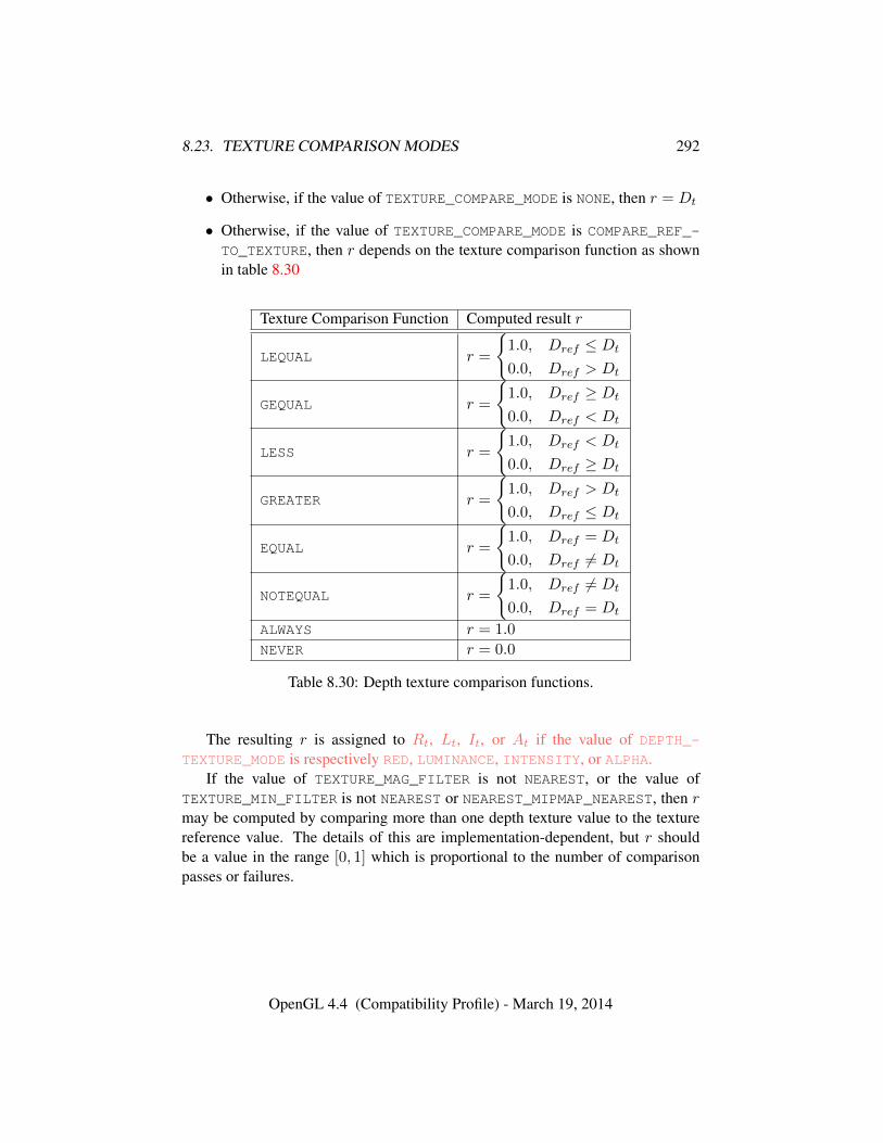
8.23. TEXTURE COMPARISON MODES 292
• Otherwise, if the value of TEXTURE_COMPARE_MODE is NONE, then r = Dt
• Otherwise, if the value of TEXTURE_COMPARE_MODE is COMPARE_REF_-TO_TEXTURE, then r depends on the texture comparison function as shownin table 8.30
Texture Comparison Function Computed result r
LEQUAL r =
{1.0, Dref ≤ Dt
0.0, Dref > Dt
GEQUAL r =
{1.0, Dref ≥ Dt
0.0, Dref < Dt
LESS r =
{1.0, Dref < Dt
0.0, Dref ≥ Dt
GREATER r =
{1.0, Dref > Dt
0.0, Dref ≤ Dt
EQUAL r =
{1.0, Dref = Dt
0.0, Dref 6= Dt
NOTEQUAL r =
{1.0, Dref 6= Dt
0.0, Dref = Dt
ALWAYS r = 1.0
NEVER r = 0.0
Table 8.30: Depth texture comparison functions.
The resulting r is assigned to Rt, Lt, It, or At if the value of DEPTH_-
TEXTURE_MODE is respectively RED, LUMINANCE, INTENSITY, or ALPHA.If the value of TEXTURE_MAG_FILTER is not NEAREST, or the value of
TEXTURE_MIN_FILTER is not NEAREST or NEAREST_MIPMAP_NEAREST, then rmay be computed by comparing more than one depth texture value to the texturereference value. The details of this are implementation-dependent, but r shouldbe a value in the range [0, 1] which is proportional to the number of comparisonpasses or failures.
OpenGL 4.4 (Compatibility Profile) - March 19, 2014
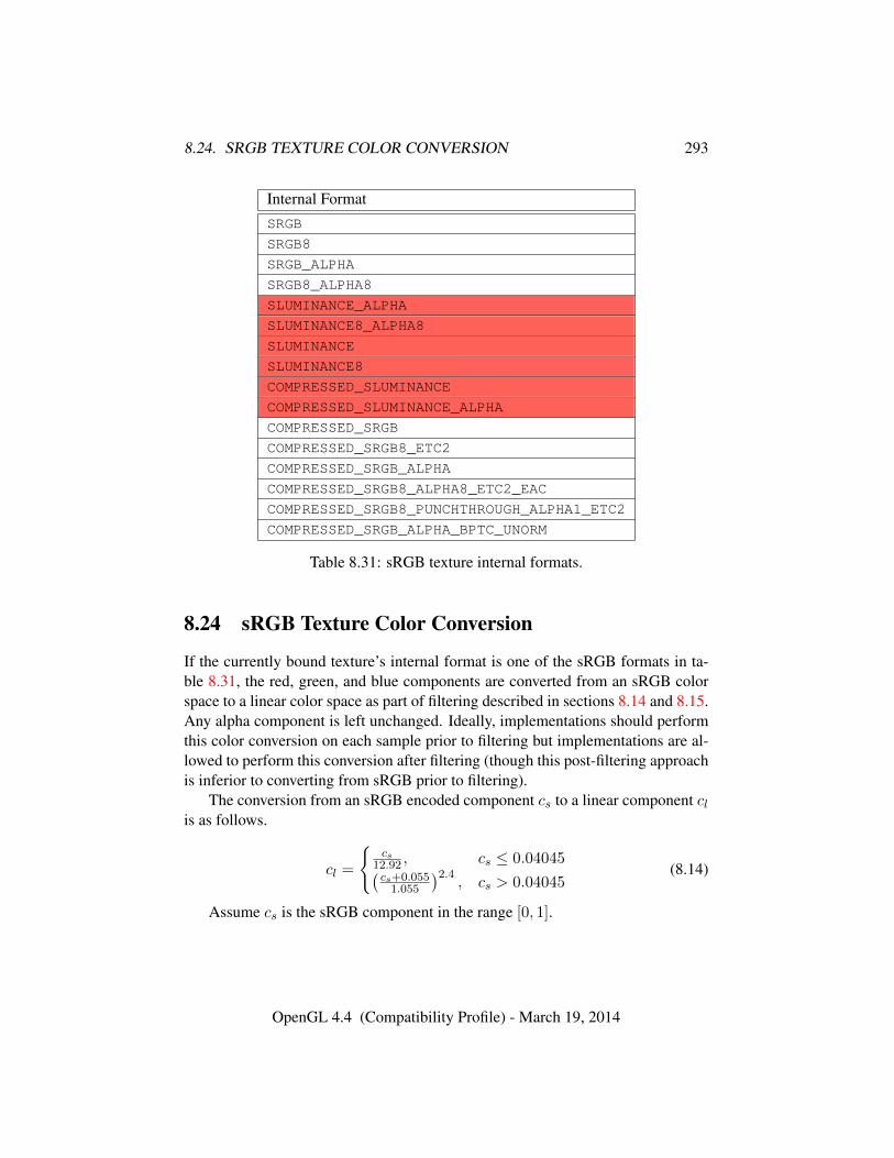
8.24. SRGB TEXTURE COLOR CONVERSION 293
Internal FormatSRGB
SRGB8
SRGB_ALPHA
SRGB8_ALPHA8
SLUMINANCE_ALPHA
SLUMINANCE8_ALPHA8
SLUMINANCE
SLUMINANCE8
COMPRESSED_SLUMINANCE
COMPRESSED_SLUMINANCE_ALPHA
COMPRESSED_SRGB
COMPRESSED_SRGB8_ETC2
COMPRESSED_SRGB_ALPHA
COMPRESSED_SRGB8_ALPHA8_ETC2_EAC
COMPRESSED_SRGB8_PUNCHTHROUGH_ALPHA1_ETC2
COMPRESSED_SRGB_ALPHA_BPTC_UNORM
Table 8.31: sRGB texture internal formats.
8.24 sRGB Texture Color Conversion
If the currently bound texture’s internal format is one of the sRGB formats in ta-ble 8.31, the red, green, and blue components are converted from an sRGB colorspace to a linear color space as part of filtering described in sections 8.14 and 8.15.Any alpha component is left unchanged. Ideally, implementations should performthis color conversion on each sample prior to filtering but implementations are al-lowed to perform this conversion after filtering (though this post-filtering approachis inferior to converting from sRGB prior to filtering).
The conversion from an sRGB encoded component cs to a linear component clis as follows.
cl =
{cs
12.92 , cs ≤ 0.04045(cs+0.0551.055
)2.4, cs > 0.04045
(8.14)
Assume cs is the sRGB component in the range [0, 1].
OpenGL 4.4 (Compatibility Profile) - March 19, 2014
8.25. SHARED EXPONENT TEXTURE COLOR CONVERSION 294
8.25 Shared Exponent Texture Color Conversion
If the currently bound texture’s internal format is RGB9_E5, the red, green, blue,and shared bits are converted to color components (prior to filtering) using sharedexponent decoding. The component reds, greens, blues, and exps values (seesection 8.5.2) are treated as unsigned integers and are converted to floating-pointred, green, and blue as follows:
red = reds2exps−B−N
green = greens2exps−B−N
blue = blues2exps−B−N
8.26 Texture Image Loads and Stores
The contents of a texture may be made available for shaders to read and write bybinding the texture to one of a collection of image units. The GL implementa-tion provides an array of image units numbered beginning with zero, with the totalnumber of image units provided given by the implementation-dependent value ofMAX_IMAGE_UNITS. Unlike texture image units, image units do not have a sepa-rate attachment for each texture target texture; each image unit may have only onetexture bound at a time.
A texture may be bound to an image unit for use by image loads and storeswith the command
void BindImageTexture( uint unit, uint texture, int level,boolean layered, int layer, enum access, enum format );
where unit identifies the image unit, texture is the name of the texture, and levelselects a single level of the texture. If texture is zero, any texture currently boundto image unit unit is unbound.
If the texture identified by texture is a one-dimensional array, two-dimensionalarray, three-dimensional, cube map, cube map array, or two-dimensional multi-sample array texture, it is possible to bind either the entire texture level or a singlelayer or face of the texture level. If layered is TRUE, the entire level is bound. Iflayered is FALSE, only the single layer identified by layer will be bound. Whenlayered is FALSE, the single bound layer is treated as a different texture target forimage accesses:
• one-dimensional array texture layers are treated as one-dimensional textures;
OpenGL 4.4 (Compatibility Profile) - March 19, 2014
8.26. TEXTURE IMAGE LOADS AND STORES 295
• two-dimensional array, three-dimensional, cube map, cube map array texturelayers are treated as two-dimensional textures; and
• two-dimensional multisample array textures are treated as two-dimensionalmultisample textures.
For cube map textures where layered is FALSE, the face is taken by mappingthe layer number to a face according to table 9.2. For cube map array textureswhere layered is FALSE, the selected layer number is mapped to a texture layerand cube face using the following equations and mapping face to a face accordingto table 9.2.
layer =
⌊layerorig
6
⌋face = layerorig − (layer × 6)
If the texture identified by texture does not have multiple layers or faces, theentire texture level is bound, regardless of the values specified for layered andlayer.
format specifies the format that the elements of the image will be treated aswhen doing formatted stores, as described later in this section. This is referred toas the image unit format.
access specifies whether the texture bound to the image will be treated asREAD_ONLY, WRITE_ONLY, or READ_WRITE. If a shader reads from an image unitwith a texture bound as WRITE_ONLY, or writes to an image unit with a texturebound as READ_ONLY, the results of that shader operation are undefined and maylead to application termination.
If a texture object bound to one or more image units is deleted by DeleteTex-tures, it is detached from each such image unit, as though BindImageTexturewere called with unit identifying the image unit and texture set to zero.
Errors
An INVALID_VALUE error is generated if unit is greater than or equal tothe value of MAX_IMAGE_UNITS, if level or layer is negative, or if texture isnot the name of an existing texture object.
An INVALID_VALUE error is generated if format is not one of the formatslisted in table 8.33.
The command
OpenGL 4.4 (Compatibility Profile) - March 19, 2014
8.26. TEXTURE IMAGE LOADS AND STORES 296
void BindImageTextures( uint first, sizei count, constuint *textures );
binds count existing texture objects to image units numbered first through first+count − 1. If textures is not NULL, it specifies an array of count values, each ofwhich must be zero or the name of an existing texture object. If textures is NULL,each affected image unit from first through first+ count− 1 will be reset to haveno bound texture object.
When binding a non-zero texture object to an image unit, the image unit level,layered, layer, and access parameters are set to zero, TRUE, zero, and READ_-
WRITE, respectively. The image unit format parameter is taken from the internalformat of the texture image at level zero of the texture object identified by tex-tures. For cube map textures, the internal format of the TEXTURE_CUBE_MAP_-
POSITIVE_X image of level zero is used. For multisample, multisample array,buffer, and rectangle textures, the internal format of the single texture level is used.
When unbinding a texture object from an image unit, the image unit parameterslevel, layered, layer, and format will be reset to their default values of zero, FALSE,0, and R8, respectively.
BindImageTextures is equivalent to
for (i = 0; i < count; i++) {if (textures == NULL || textures[i] = 0) {
BindImageTexture(first + i, 0, 0, FALSE, 0,READ_ONLY, R8);
} else {BindImageTexture(first + i, textures[i], 0, TRUE, 0,
READ_WRITE, lookupInternalFormat(textures[i]));}
}
where lookupInternalFormat returns the internal format of the specifiedtexture object.
The values specified in textures will be checked separately for each image unit.When a value for a specific image unit is invalid, the state for that image unit willbe unchanged and an error will be generated. However, state for other image unitswill still be changed if their corresponding values are valid.
Errors
An INVALID_OPERATION error is generated if first + count is greaterthan the number of image units supported by the implementation.
OpenGL 4.4 (Compatibility Profile) - March 19, 2014
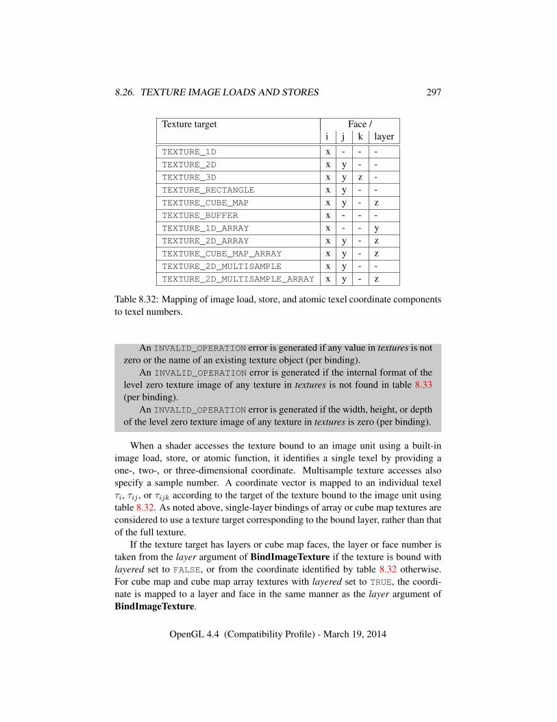
8.26. TEXTURE IMAGE LOADS AND STORES 297
Texture target Face /i j k layer
TEXTURE_1D x - - -TEXTURE_2D x y - -TEXTURE_3D x y z -TEXTURE_RECTANGLE x y - -TEXTURE_CUBE_MAP x y - zTEXTURE_BUFFER x - - -TEXTURE_1D_ARRAY x - - yTEXTURE_2D_ARRAY x y - zTEXTURE_CUBE_MAP_ARRAY x y - zTEXTURE_2D_MULTISAMPLE x y - -TEXTURE_2D_MULTISAMPLE_ARRAY x y - z
Table 8.32: Mapping of image load, store, and atomic texel coordinate componentsto texel numbers.
An INVALID_OPERATION error is generated if any value in textures is notzero or the name of an existing texture object (per binding).
An INVALID_OPERATION error is generated if the internal format of thelevel zero texture image of any texture in textures is not found in table 8.33(per binding).
An INVALID_OPERATION error is generated if the width, height, or depthof the level zero texture image of any texture in textures is zero (per binding).
When a shader accesses the texture bound to an image unit using a built-inimage load, store, or atomic function, it identifies a single texel by providing aone-, two-, or three-dimensional coordinate. Multisample texture accesses alsospecify a sample number. A coordinate vector is mapped to an individual texelτi, τij , or τijk according to the target of the texture bound to the image unit usingtable 8.32. As noted above, single-layer bindings of array or cube map textures areconsidered to use a texture target corresponding to the bound layer, rather than thatof the full texture.
If the texture target has layers or cube map faces, the layer or face number istaken from the layer argument of BindImageTexture if the texture is bound withlayered set to FALSE, or from the coordinate identified by table 8.32 otherwise.For cube map and cube map array textures with layered set to TRUE, the coordi-nate is mapped to a layer and face in the same manner as the layer argument ofBindImageTexture.
OpenGL 4.4 (Compatibility Profile) - March 19, 2014
8.26. TEXTURE IMAGE LOADS AND STORES 298
If the individual texel identified for an image load, store, or atomic operationdoesn’t exist, the access is treated as invalid. Invalid image loads will return zero.Invalid image stores will have no effect. Invalid image atomics will not updateany texture bound to the image unit and will return zero. An access is consideredinvalid if:
• no texture is bound to the selected image unit;
• the texture bound to the selected image unit is incomplete;
• the texture level bound to the image unit is less than the base level or greaterthan the maximum level of the texture;
• the texture bound to the image unit is bordered;
• the internal format of the texture bound to the image unit is not found intable 8.33;
• the internal format of the texture bound to the image unit is incompatiblewith the specified format according to table 8.34;
• the texture bound to the image unit has layers, and the selected layer or cubemap face doesn’t exist;
• the selected texel τi, τij , or τijk doesn’t exist;
• the image has more samples than the implementation-dependent value ofMAX_IMAGE_SAMPLES.
Additionally, there are a number of cases where image load, store, or atomicoperations are considered to involve a format mismatch. In such cases, undefinedvalues will be returned by image loads and atomic operations and undefined valueswill be written by stores and atomic operations. A format mismatch will occur if:
• the type of image variable used to access the image unit does not match thetarget of a texture bound to the image unit with layered set to TRUE;
• the type of image variable used to access the image unit does not match thetarget corresponding to a single layer of a multi-layer texture target bound tothe image unit with layered set to FALSE;
• the type of image variable used to access the image unit has a component datatype (floating-point, signed integer, unsigned integer) incompatible with theformat of the image unit;
OpenGL 4.4 (Compatibility Profile) - March 19, 2014
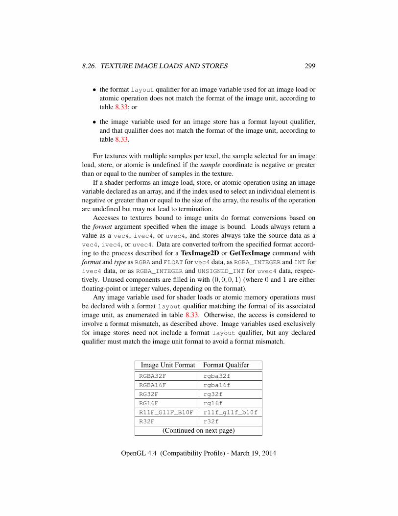
8.26. TEXTURE IMAGE LOADS AND STORES 299
• the format layout qualifier for an image variable used for an image load oratomic operation does not match the format of the image unit, according totable 8.33; or
• the image variable used for an image store has a format layout qualifier,and that qualifier does not match the format of the image unit, according totable 8.33.
For textures with multiple samples per texel, the sample selected for an imageload, store, or atomic is undefined if the sample coordinate is negative or greaterthan or equal to the number of samples in the texture.
If a shader performs an image load, store, or atomic operation using an imagevariable declared as an array, and if the index used to select an individual element isnegative or greater than or equal to the size of the array, the results of the operationare undefined but may not lead to termination.
Accesses to textures bound to image units do format conversions based onthe format argument specified when the image is bound. Loads always return avalue as a vec4, ivec4, or uvec4, and stores always take the source data as avec4, ivec4, or uvec4. Data are converted to/from the specified format accord-ing to the process described for a TexImage2D or GetTexImage command withformat and type as RGBA and FLOAT for vec4 data, as RGBA_INTEGER and INT forivec4 data, or as RGBA_INTEGER and UNSIGNED_INT for uvec4 data, respec-tively. Unused components are filled in with (0, 0, 0, 1) (where 0 and 1 are eitherfloating-point or integer values, depending on the format).
Any image variable used for shader loads or atomic memory operations mustbe declared with a format layout qualifier matching the format of its associatedimage unit, as enumerated in table 8.33. Otherwise, the access is considered toinvolve a format mismatch, as described above. Image variables used exclusivelyfor image stores need not include a format layout qualifier, but any declaredqualifier must match the image unit format to avoid a format mismatch.
Image Unit Format Format QualiferRGBA32F rgba32f
RGBA16F rgba16f
RG32F rg32f
RG16F rg16f
R11F_G11F_B10F r11f_g11f_b10f
R32F r32f
(Continued on next page)
OpenGL 4.4 (Compatibility Profile) - March 19, 2014
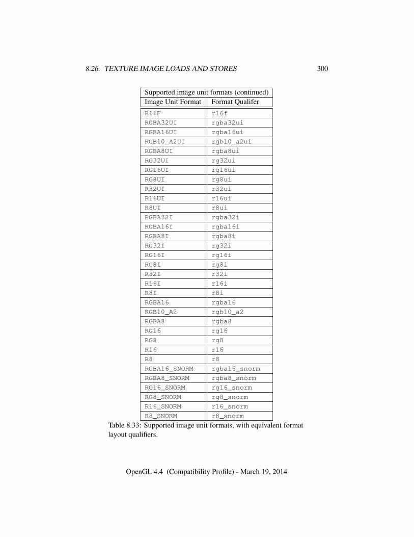
8.26. TEXTURE IMAGE LOADS AND STORES 300
Supported image unit formats (continued)Image Unit Format Format QualiferR16F r16f
RGBA32UI rgba32ui
RGBA16UI rgba16ui
RGB10_A2UI rgb10_a2ui
RGBA8UI rgba8ui
RG32UI rg32ui
RG16UI rg16ui
RG8UI rg8ui
R32UI r32ui
R16UI r16ui
R8UI r8ui
RGBA32I rgba32i
RGBA16I rgba16i
RGBA8I rgba8i
RG32I rg32i
RG16I rg16i
RG8I rg8i
R32I r32i
R16I r16i
R8I r8i
RGBA16 rgba16
RGB10_A2 rgb10_a2
RGBA8 rgba8
RG16 rg16
RG8 rg8
R16 r16
R8 r8
RGBA16_SNORM rgba16_snorm
RGBA8_SNORM rgba8_snorm
RG16_SNORM rg16_snorm
RG8_SNORM rg8_snorm
R16_SNORM r16_snorm
R8_SNORM r8_snorm
Table 8.33: Supported image unit formats, with equivalent formatlayout qualifiers.
OpenGL 4.4 (Compatibility Profile) - March 19, 2014
8.26. TEXTURE IMAGE LOADS AND STORES 301
When a texture is bound to an image unit, the format parameter for the imageunit need not exactly match the texture internal format as long as the formats areconsidered compatible. A pair of formats is considered to match in size if the cor-responding entries in the Size column of table 8.34 are identical. A pair of formatsis considered to match by class if the corresponding entries in the Class columnof table 8.34 are identical. For textures allocated by the GL, an image unit formatis compatible with a texture internal format if they match by size. For texturesallocated outside the GL, format compatibility is determined by matching by sizeor by class, in an implementation dependent manner. The matching criterion usedfor a given texture may be determined by calling GetTexParameter with pnameset to IMAGE_FORMAT_COMPATIBILITY_TYPE, with return values of IMAGE_-FORMAT_COMPATIBILITY_BY_SIZE and IMAGE_FORMAT_COMPATIBILITY_-
BY_CLASS, specifying matches by size and class, respectively.When the format associated with an image unit does not exactly match the
internal format of the texture bound to the image unit, image loads, stores, andatomic operations re-interpret the memory holding the components of an accessedtexel according to the format of the image unit. The re-interpretation for imageloads and the read portion of image atomics is performed as though data werecopied from the texel of the bound texture to a similar texel represented in theformat of the image unit. Similarly, the re-interpretation for image stores and thewrite portion of image atomics is performed as though data were copied from atexel represented in the format of the image unit to the texel in the bound texture.In both cases, this copy operation would be performed by:
• reading the texel from the source format to scratch memory according to theprocess described for GetTexImage (see section 8.11), using default pixelstorage modes and format and type parameters corresponding to the sourceformat in table 8.34; and
• writing the texel from scratch memory to the destination format according tothe process described for TexSubImage3D (see section 8.6), using defaultpixel storage modes and format and type parameters corresponding to thedestination format in table 8.34.
No pixel transfer operations are performed during this conversion.
OpenGL 4.4 (Compatibility Profile) - March 19, 2014
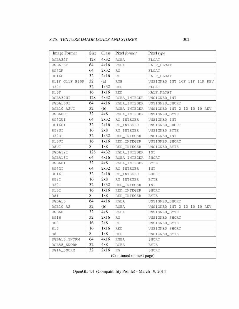
8.26. TEXTURE IMAGE LOADS AND STORES 302
Image Format Size Class Pixel format Pixel type
RGBA32F 128 4x32 RGBA FLOAT
RGBA16F 64 4x16 RGBA HALF_FLOAT
RG32F 64 2x32 RG FLOAT
RG16F 32 2x16 RG HALF_FLOAT
R11F_G11F_B10F 32 (a) RGB UNSIGNED_INT_10F_11F_11F_REV
R32F 32 1x32 RED FLOAT
R16F 16 1x16 RED HALF_FLOAT
RGBA32UI 128 4x32 RGBA_INTEGER UNSIGNED_INT
RGBA16UI 64 4x16 RGBA_INTEGER UNSIGNED_SHORT
RGB10_A2UI 32 (b) RGBA_INTEGER UNSIGNED_INT_2_10_10_10_REV
RGBA8UI 32 4x8 RGBA_INTEGER UNSIGNED_BYTE
RG32UI 64 2x32 RG_INTEGER UNSIGNED_INT
RG16UI 32 2x16 RG_INTEGER UNSIGNED_SHORT
RG8UI 16 2x8 RG_INTEGER UNSIGNED_BYTE
R32UI 32 1x32 RED_INTEGER UNSIGNED_INT
R16UI 16 1x16 RED_INTEGER UNSIGNED_SHORT
R8UI 8 1x8 RED_INTEGER UNSIGNED_BYTE
RGBA32I 128 4x32 RGBA_INTEGER INT
RGBA16I 64 4x16 RGBA_INTEGER SHORT
RGBA8I 32 4x8 RGBA_INTEGER BYTE
RG32I 64 2x32 RG_INTEGER INT
RG16I 32 2x16 RG_INTEGER SHORT
RG8I 16 2x8 RG_INTEGER BYTE
R32I 32 1x32 RED_INTEGER INT
R16I 16 1x16 RED_INTEGER SHORT
R8I 8 1x8 RED_INTEGER BYTE
RGBA16 64 4x16 RGBA UNSIGNED_SHORT
RGB10_A2 32 (b) RGBA UNSIGNED_INT_2_10_10_10_REV
RGBA8 32 4x8 RGBA UNSIGNED_BYTE
RG16 32 2x16 RG UNSIGNED_SHORT
RG8 16 2x8 RG UNSIGNED_BYTE
R16 16 1x16 RED UNSIGNED_SHORT
R8 8 1x8 RED UNSIGNED_BYTE
RGBA16_SNORM 64 4x16 RGBA SHORT
RGBA8_SNORM 32 4x8 RGBA BYTE
RG16_SNORM 32 2x16 RG SHORT
(Continued on next page)
OpenGL 4.4 (Compatibility Profile) - March 19, 2014
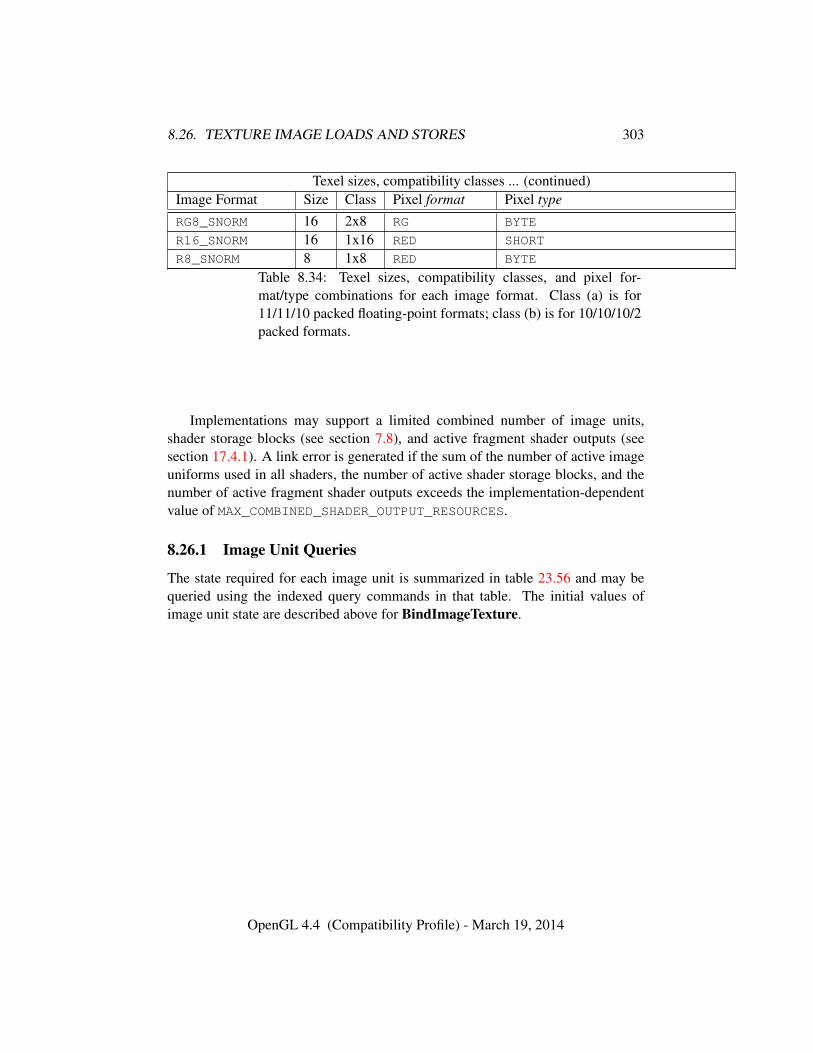
8.26. TEXTURE IMAGE LOADS AND STORES 303
Texel sizes, compatibility classes ... (continued)Image Format Size Class Pixel format Pixel type
RG8_SNORM 16 2x8 RG BYTE
R16_SNORM 16 1x16 RED SHORT
R8_SNORM 8 1x8 RED BYTE
Table 8.34: Texel sizes, compatibility classes, and pixel for-mat/type combinations for each image format. Class (a) is for11/11/10 packed floating-point formats; class (b) is for 10/10/10/2packed formats.
Implementations may support a limited combined number of image units,shader storage blocks (see section 7.8), and active fragment shader outputs (seesection 17.4.1). A link error is generated if the sum of the number of active imageuniforms used in all shaders, the number of active shader storage blocks, and thenumber of active fragment shader outputs exceeds the implementation-dependentvalue of MAX_COMBINED_SHADER_OUTPUT_RESOURCES.
8.26.1 Image Unit Queries
The state required for each image unit is summarized in table 23.56 and may bequeried using the indexed query commands in that table. The initial values ofimage unit state are described above for BindImageTexture.
OpenGL 4.4 (Compatibility Profile) - March 19, 2014
Chapter 9
Framebuffers and FramebufferObjects
As described in chapter 1 and section 2.1, the GL renders into (and reads valuesfrom) a framebuffer.
Initially, the GL uses the window-system provided default framebuffer. Thestorage, dimensions, allocation, and format of the images attached to this frame-buffer are managed entirely by the window system. Consequently, the state of thedefault framebuffer, including its images, can not be changed by the GL, nor canthe default framebuffer be deleted by the GL.
This chapter begins with an overview of the structure and contents of the frame-buffer in section 9.1, followed by describing the commands used to create, destroy,and modify the state and attachments of application-created framebuffer objectswhich may be used instead of the default framebuffer.
9.1 Framebuffer Overview
The framebuffer consists of a set of pixels arranged as a two-dimensional array.For purposes of this discussion, each pixel in the framebuffer is simply a set ofsome number of bits. The number of bits per pixel may vary depending on the GLimplementation, the type of framebuffer selected, and parameters specified whenthe framebuffer was created. Creation and management of the default framebufferis outside the scope of this specification, while creation and management of frame-buffer objects is described in detail in section 9.2.
Corresponding bits from each pixel in the framebuffer are grouped together intoa bitplane; each bitplane contains a single bit from each pixel. These bitplanes aregrouped into several logical buffers. These are the color, accumulation, depth, and
304
9.1. FRAMEBUFFER OVERVIEW 305
stencil buffers. The color buffer actually consists of a number of buffers, and thesecolor buffers serve related but slightly different purposes depending on whether theGL is bound to the default framebuffer or a framebuffer object.
For the default framebuffer, the color buffers are the front left buffer, the frontright buffer, the back left buffer, the back right buffer, and some number of auxil-iary buffers. Typically the contents of the front buffers are displayed on a colormonitor while the contents of the back buffers are invisible. (Monoscopic contextsdisplay only the front left buffer; stereoscopic contexts display both the front leftand the front right buffers.) The contents of the auxiliary buffers are never visible.All color buffers must have the same number of bitplanes, although an implemen-tation or context may choose not to provide right buffers, back buffers, or auxiliarybuffers at all. Further, an implementation or context may choose not to provideaccumulation, depth or stencil buffers. If no default framebuffer is associated withthe GL context, the framebuffer is incomplete except when a framebuffer object isbound (see sections 9.2 and 9.4).
Framebuffer objects are not visible, and do not have any of the color bufferspresent in the default framebuffer. Instead, the buffers of an framebuffer object arespecified by attaching individual textures or renderbuffers (see section 9) to a setof attachment points. A framebuffer object has an array of color buffer attachmentpoints, numbered zero through n, a depth buffer attachment point, and a stencilbuffer attachment point. In order to be used for rendering, a framebuffer objectmust be complete, as described in section 9.4. Not all attachments of a framebufferobject need to be populated.
Each pixel in a color buffer consists of either a single unsigned integer colorindex or up to four color components. The four color components are named R, G,B, and A, in that order; color buffers are not required to have all four color com-ponents. R, G, B, and A components may be represented as signed or unsignednormalized fixed-point, floating-point, or signed or unsigned integer values; allcomponents must have the same representation. Each pixel in a depth buffer con-sists of a single unsigned integer value in the format described in section 13.6.1 ora floating-point value. Each pixel in a stencil buffer consists of a single unsignedinteger value. Each pixel in an accumulation buffer consists of up to four colorcomponents. If an accumulation buffer is present, it must have at least as manybitplanes per component as in the color buffers.
The number of bitplanes in the accumulation, color, depth, and stencil buffersis dependent on the currently bound framebuffer. For the default framebuffer, thenumber of bitplanes is fixed. For framebuffer objects, the number of bitplanesin a given logical buffer may change if the image attached to the correspondingattachment point changes.
The GL has two active framebuffers; the draw framebuffer is the destination
OpenGL 4.4 (Compatibility Profile) - March 19, 2014
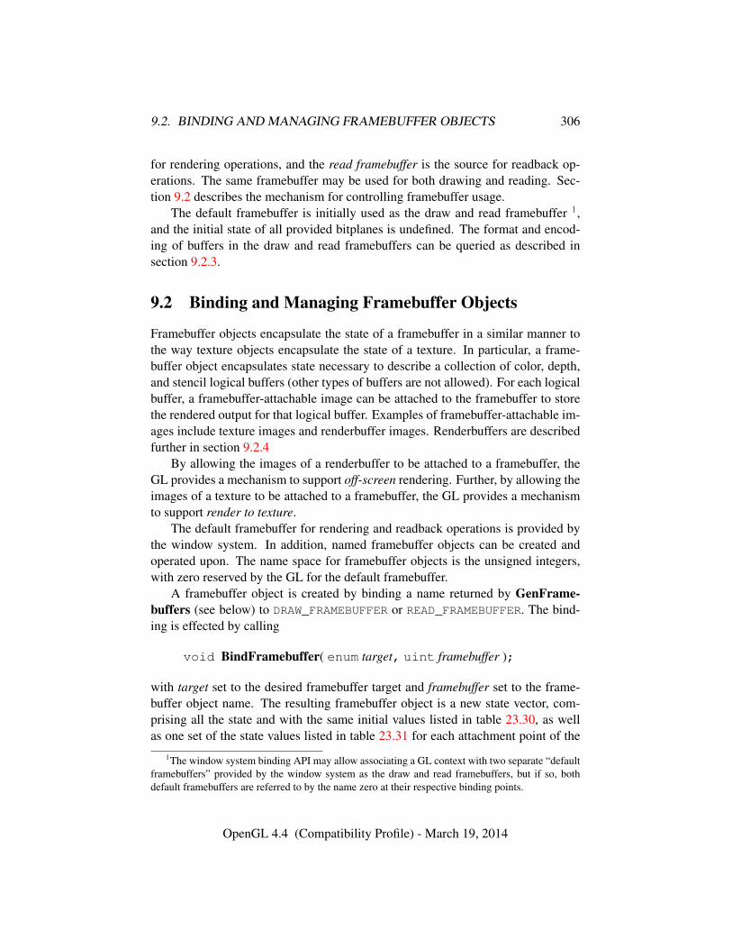
9.2. BINDING AND MANAGING FRAMEBUFFER OBJECTS 306
for rendering operations, and the read framebuffer is the source for readback op-erations. The same framebuffer may be used for both drawing and reading. Sec-tion 9.2 describes the mechanism for controlling framebuffer usage.
The default framebuffer is initially used as the draw and read framebuffer 1,and the initial state of all provided bitplanes is undefined. The format and encod-ing of buffers in the draw and read framebuffers can be queried as described insection 9.2.3.
9.2 Binding and Managing Framebuffer Objects
Framebuffer objects encapsulate the state of a framebuffer in a similar manner tothe way texture objects encapsulate the state of a texture. In particular, a frame-buffer object encapsulates state necessary to describe a collection of color, depth,and stencil logical buffers (other types of buffers are not allowed). For each logicalbuffer, a framebuffer-attachable image can be attached to the framebuffer to storethe rendered output for that logical buffer. Examples of framebuffer-attachable im-ages include texture images and renderbuffer images. Renderbuffers are describedfurther in section 9.2.4
By allowing the images of a renderbuffer to be attached to a framebuffer, theGL provides a mechanism to support off-screen rendering. Further, by allowing theimages of a texture to be attached to a framebuffer, the GL provides a mechanismto support render to texture.
The default framebuffer for rendering and readback operations is provided bythe window system. In addition, named framebuffer objects can be created andoperated upon. The name space for framebuffer objects is the unsigned integers,with zero reserved by the GL for the default framebuffer.
A framebuffer object is created by binding a name returned by GenFrame-buffers (see below) to DRAW_FRAMEBUFFER or READ_FRAMEBUFFER. The bind-ing is effected by calling
void BindFramebuffer( enum target, uint framebuffer );
with target set to the desired framebuffer target and framebuffer set to the frame-buffer object name. The resulting framebuffer object is a new state vector, com-prising all the state and with the same initial values listed in table 23.30, as wellas one set of the state values listed in table 23.31 for each attachment point of the
1The window system binding API may allow associating a GL context with two separate “defaultframebuffers” provided by the window system as the draw and read framebuffers, but if so, bothdefault framebuffers are referred to by the name zero at their respective binding points.
OpenGL 4.4 (Compatibility Profile) - March 19, 2014
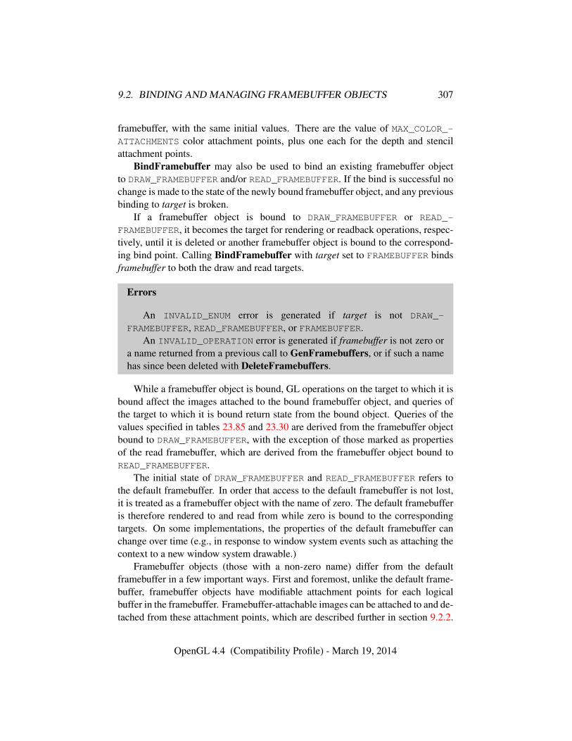
9.2. BINDING AND MANAGING FRAMEBUFFER OBJECTS 307
framebuffer, with the same initial values. There are the value of MAX_COLOR_-ATTACHMENTS color attachment points, plus one each for the depth and stencilattachment points.
BindFramebuffer may also be used to bind an existing framebuffer objectto DRAW_FRAMEBUFFER and/or READ_FRAMEBUFFER. If the bind is successful nochange is made to the state of the newly bound framebuffer object, and any previousbinding to target is broken.
If a framebuffer object is bound to DRAW_FRAMEBUFFER or READ_-
FRAMEBUFFER, it becomes the target for rendering or readback operations, respec-tively, until it is deleted or another framebuffer object is bound to the correspond-ing bind point. Calling BindFramebuffer with target set to FRAMEBUFFER bindsframebuffer to both the draw and read targets.
Errors
An INVALID_ENUM error is generated if target is not DRAW_-
FRAMEBUFFER, READ_FRAMEBUFFER, or FRAMEBUFFER.An INVALID_OPERATION error is generated if framebuffer is not zero or
a name returned from a previous call to GenFramebuffers, or if such a namehas since been deleted with DeleteFramebuffers.
While a framebuffer object is bound, GL operations on the target to which it isbound affect the images attached to the bound framebuffer object, and queries ofthe target to which it is bound return state from the bound object. Queries of thevalues specified in tables 23.85 and 23.30 are derived from the framebuffer objectbound to DRAW_FRAMEBUFFER, with the exception of those marked as propertiesof the read framebuffer, which are derived from the framebuffer object bound toREAD_FRAMEBUFFER.
The initial state of DRAW_FRAMEBUFFER and READ_FRAMEBUFFER refers tothe default framebuffer. In order that access to the default framebuffer is not lost,it is treated as a framebuffer object with the name of zero. The default framebufferis therefore rendered to and read from while zero is bound to the correspondingtargets. On some implementations, the properties of the default framebuffer canchange over time (e.g., in response to window system events such as attaching thecontext to a new window system drawable.)
Framebuffer objects (those with a non-zero name) differ from the defaultframebuffer in a few important ways. First and foremost, unlike the default frame-buffer, framebuffer objects have modifiable attachment points for each logicalbuffer in the framebuffer. Framebuffer-attachable images can be attached to and de-tached from these attachment points, which are described further in section 9.2.2.
OpenGL 4.4 (Compatibility Profile) - March 19, 2014

9.2. BINDING AND MANAGING FRAMEBUFFER OBJECTS 308
Also, the size and format of the images attached to framebuffer objects are con-trolled entirely within the GL interface, and are not affected by window systemevents, such as pixel format selection, window resizes, and display mode changes.
Additionally, when rendering to or reading from an application created-framebuffer object,
• The pixel ownership test always succeeds. In other words, framebuffer ob-jects own all of their pixels.
• There are no visible color buffer bitplanes. This means there is no colorbuffer corresponding to the back, front, left, or right color bitplanes.
• The only color buffer bitplanes are the ones defined by the frame-buffer attachment points named COLOR_ATTACHMENT0 through COLOR_-
ATTACHMENTn. Each COLOR_ATTACHMENTi adheres to COLOR_-
ATTACHMENTi = COLOR_ATTACHMENT0 + i.
• The only depth buffer bitplanes are the ones defined by the framebuffer at-tachment point DEPTH_ATTACHMENT.
• The only stencil buffer bitplanes are the ones defined by the framebufferattachment point STENCIL_ATTACHMENT.
• There are no accumulation buffer bitplanes, so the value of theimplementation-dependent state variables ACCUM_RED_BITS, ACCUM_-
GREEN_BITS, ACCUM_BLUE_BITS, and ACCUM_ALPHA_BITS are all zero.
• There are no auxiliary buffer bitplanes, so the value of the implementation-dependent state variable AUX_BUFFERS is zero.
• If the attachment sizes are not all identical, rendering will be limited to thelargest area that can fit in all of the attachments (an intersection of rectangleshaving a lower left of (0, 0) and an upper right of (width, height) for eachattachment). If there are no attachments, rendering will be limited to a rect-angle having a lower left of (0, 0) and an upper right of (width, height),where width and height are the framebuffer object’s default width andheight.
• If the number of layers of each attachment are not all identical, renderingwill be limited to the smallest number of layers of any attachment. If thereare no attachments, the number of layers will be taken from the framebufferobject’s default layer count.
OpenGL 4.4 (Compatibility Profile) - March 19, 2014
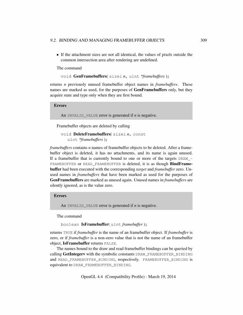
9.2. BINDING AND MANAGING FRAMEBUFFER OBJECTS 309
• If the attachment sizes are not all identical, the values of pixels outside thecommon intersection area after rendering are undefined.
The command
void GenFramebuffers( sizei n, uint *framebuffers );
returns n previously unused framebuffer object names in framebuffers. Thesenames are marked as used, for the purposes of GenFramebuffers only, but theyacquire state and type only when they are first bound.
Errors
An INVALID_VALUE error is generated if n is negative.
Framebuffer objects are deleted by calling
void DeleteFramebuffers( sizei n, constuint *framebuffers );
framebuffers contains n names of framebuffer objects to be deleted. After a frame-buffer object is deleted, it has no attachments, and its name is again unused.If a framebuffer that is currently bound to one or more of the targets DRAW_-
FRAMEBUFFER or READ_FRAMEBUFFER is deleted, it is as though BindFrame-buffer had been executed with the corresponding target and framebuffer zero. Un-used names in framebuffers that have been marked as used for the purposes ofGenFramebuffers are marked as unused again. Unused names in framebuffers aresilently ignored, as is the value zero.
Errors
An INVALID_VALUE error is generated if n is negative.
The command
boolean IsFramebuffer( uint framebuffer );
returns TRUE if framebuffer is the name of an framebuffer object. If framebuffer iszero, or if framebuffer is a non-zero value that is not the name of an framebufferobject, IsFramebuffer returns FALSE.
The names bound to the draw and read framebuffer bindings can be queried bycalling GetIntegerv with the symbolic constants DRAW_FRAMEBUFFER_BINDINGand READ_FRAMEBUFFER_BINDING, respectively. FRAMEBUFFER_BINDING isequivalent to DRAW_FRAMEBUFFER_BINDING.
OpenGL 4.4 (Compatibility Profile) - March 19, 2014
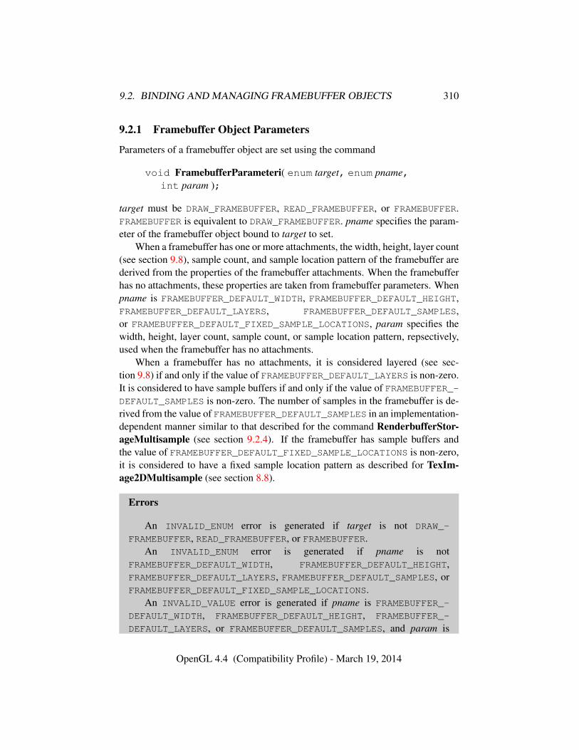
9.2. BINDING AND MANAGING FRAMEBUFFER OBJECTS 310
9.2.1 Framebuffer Object Parameters
Parameters of a framebuffer object are set using the command
void FramebufferParameteri( enum target, enum pname,int param );
target must be DRAW_FRAMEBUFFER, READ_FRAMEBUFFER, or FRAMEBUFFER.FRAMEBUFFER is equivalent to DRAW_FRAMEBUFFER. pname specifies the param-eter of the framebuffer object bound to target to set.
When a framebuffer has one or more attachments, the width, height, layer count(see section 9.8), sample count, and sample location pattern of the framebuffer arederived from the properties of the framebuffer attachments. When the framebufferhas no attachments, these properties are taken from framebuffer parameters. Whenpname is FRAMEBUFFER_DEFAULT_WIDTH, FRAMEBUFFER_DEFAULT_HEIGHT,FRAMEBUFFER_DEFAULT_LAYERS, FRAMEBUFFER_DEFAULT_SAMPLES,or FRAMEBUFFER_DEFAULT_FIXED_SAMPLE_LOCATIONS, param specifies thewidth, height, layer count, sample count, or sample location pattern, repsectively,used when the framebuffer has no attachments.
When a framebuffer has no attachments, it is considered layered (see sec-tion 9.8) if and only if the value of FRAMEBUFFER_DEFAULT_LAYERS is non-zero.It is considered to have sample buffers if and only if the value of FRAMEBUFFER_-DEFAULT_SAMPLES is non-zero. The number of samples in the framebuffer is de-rived from the value of FRAMEBUFFER_DEFAULT_SAMPLES in an implementation-dependent manner similar to that described for the command RenderbufferStor-ageMultisample (see section 9.2.4). If the framebuffer has sample buffers andthe value of FRAMEBUFFER_DEFAULT_FIXED_SAMPLE_LOCATIONS is non-zero,it is considered to have a fixed sample location pattern as described for TexIm-age2DMultisample (see section 8.8).
Errors
An INVALID_ENUM error is generated if target is not DRAW_-
FRAMEBUFFER, READ_FRAMEBUFFER, or FRAMEBUFFER.An INVALID_ENUM error is generated if pname is not
FRAMEBUFFER_DEFAULT_WIDTH, FRAMEBUFFER_DEFAULT_HEIGHT,FRAMEBUFFER_DEFAULT_LAYERS, FRAMEBUFFER_DEFAULT_SAMPLES, orFRAMEBUFFER_DEFAULT_FIXED_SAMPLE_LOCATIONS.
An INVALID_VALUE error is generated if pname is FRAMEBUFFER_-
DEFAULT_WIDTH, FRAMEBUFFER_DEFAULT_HEIGHT, FRAMEBUFFER_-
DEFAULT_LAYERS, or FRAMEBUFFER_DEFAULT_SAMPLES, and param is
OpenGL 4.4 (Compatibility Profile) - March 19, 2014
9.2. BINDING AND MANAGING FRAMEBUFFER OBJECTS 311
either negative or greater than the value of the corresponding implementation-dependent limit MAX_FRAMEBUFFER_WIDTH, MAX_FRAMEBUFFER_HEIGHT,MAX_FRAMEBUFFER_LAYERS, or MAX_FRAMEBUFFER_SAMPLES, respec-tively.
An INVALID_OPERATION error is generated if the default framebuffer isbound to target.
9.2.2 Attaching Images to Framebuffer Objects
Framebuffer-attachable images may be attached to, and detached from, framebufferobjects. In contrast, the image attachments of the default framebuffer may not bechanged by the GL.
A single framebuffer-attachable image may be attached to multiple framebufferobjects, potentially avoiding some data copies, and possibly decreasing memoryconsumption.
For each logical buffer, a framebuffer object stores a set of state which definesthe logical buffer’s attachment point. The attachment point state contains enoughinformation to identify the single image attached to the attachment point, or toindicate that no image is attached. The per-logical buffer attachment point state islisted in table 23.31
There are several types of framebuffer-attachable images:
• The image of a renderbuffer object, which is always two-dimensional.
• A single level of a one-dimensional texture, which is treated as a two-dimensional image with a height of one.
• A single level of a two-dimensional, two-dimensional multisample, or rect-angle texture.
• A single face of a cube map texture level, which is treated as a two-dimensional image.
• A single layer of a one-or two-dimensional array texture, two-dimensionalmultisample array texture, or three-dimensional texture, which is treated asa two-dimensional image.
• A single layer-face of a cube map array texture, which is treated as a two-dimensional image.
Additionally, an entire level of a three-dimensional, cube map, cube map array,or one-or two-dimensional array texture can be attached to an attachment point.
OpenGL 4.4 (Compatibility Profile) - March 19, 2014
9.2. BINDING AND MANAGING FRAMEBUFFER OBJECTS 312
Such attachments are treated as an array of two-dimensional images, arranged inlayers, and the corresponding attachment point is considered to be layered (alsosee section 9.8).
9.2.3 Framebuffer Object Queries
The command
void GetFramebufferParameteriv( enum target, enum pname,int *params );
returns the values of the framebuffer parameter pname of the framebuffer objectbound to target.
target must be DRAW_FRAMEBUFFER, READ_FRAMEBUFFER,or FRAMEBUFFER. FRAMEBUFFER is equivalent to DRAW_FRAMEBUFFER. pnamespecifies the parameter of the framebuffer object bound to target to get.
Errors
An INVALID_ENUM error is generated if target is not DRAW_-
FRAMEBUFFER, READ_FRAMEBUFFER, or FRAMEBUFFER.An INVALID_ENUM error is generated if pname is not
FRAMEBUFFER_DEFAULT_WIDTH, FRAMEBUFFER_DEFAULT_HEIGHT,FRAMEBUFFER_DEFAULT_LAYERS, FRAMEBUFFER_DEFAULT_SAMPLES, orFRAMEBUFFER_DEFAULT_FIXED_SAMPLE_LOCATIONS.
An INVALID_OPERATION error is generated if the default framebuffer isbound to target.
The command
void GetFramebufferAttachmentParameteriv( enum target,enum attachment, enum pname, int *params );
returns information about attachments of a bound framebuffer object. tar-get must be DRAW_FRAMEBUFFER, READ_FRAMEBUFFER, or FRAMEBUFFER.FRAMEBUFFER is equivalent to DRAW_FRAMEBUFFER.
If the default framebuffer is bound to target, then attachment must be one ofFRONT_LEFT, FRONT_RIGHT, BACK_LEFT, BACK_RIGHT, or AUXi, identifyinga color buffer; DEPTH, identifying the depth buffer; or STENCIL, identifying thestencil buffer.
OpenGL 4.4 (Compatibility Profile) - March 19, 2014
9.2. BINDING AND MANAGING FRAMEBUFFER OBJECTS 313
If a framebuffer object is bound to target, then attachment must be one of theattachment points of the framebuffer listed in table 9.1.
If attachment is DEPTH_STENCIL_ATTACHMENT, and different objects arebound to the depth and stencil attachment points of target, the query will fail andgenerate an INVALID_OPERATION error. If the same object is bound to both at-tachment points, information about that object will be returned.
Upon successful return from GetFramebufferAttachmentParameteriv, ifpname is FRAMEBUFFER_ATTACHMENT_OBJECT_TYPE, then params will containone of NONE, FRAMEBUFFER_DEFAULT, TEXTURE, or RENDERBUFFER, identify-ing the type of object which contains the attached image. Other values acceptedfor pname depend on the type of object, as described below.
If the value of FRAMEBUFFER_ATTACHMENT_OBJECT_TYPE is NONE, then ei-ther no framebuffer is bound to target; or the default framebuffer is bound, attach-ment is DEPTH or STENCIL, and the number of depth or stencil bits, respectively, iszero. In this case querying pname FRAMEBUFFER_ATTACHMENT_OBJECT_NAMEwill return zero, and all other queries will generate an INVALID_OPERATION error.
If the value of FRAMEBUFFER_ATTACHMENT_OBJECT_TYPE is not NONE,these queries apply to all other framebuffer types:
• If pname is FRAMEBUFFER_ATTACHMENT_RED_SIZE, FRAMEBUFFER_-
ATTACHMENT_GREEN_SIZE, FRAMEBUFFER_ATTACHMENT_BLUE_-
SIZE, FRAMEBUFFER_ATTACHMENT_ALPHA_SIZE, FRAMEBUFFER_-
ATTACHMENT_DEPTH_SIZE, or FRAMEBUFFER_ATTACHMENT_-
STENCIL_SIZE, then params will contain the number of bits in thecorresponding red, green, blue, alpha, depth, or stencil component ofthe specified attachment. If the requested component is not present inattachment, or if no data storage or texture image has been specified for theattachment, param will contain the value zero.
• If pname is FRAMEBUFFER_ATTACHMENT_COMPONENT_TYPE, param willcontain the format of components of the specified attachment, one of FLOAT,INDEX, INT, UNSIGNED_INT, SIGNED_NORMALIZED, or UNSIGNED_-
NORMALIZED for floating-point, index, signed integer, unsigned integer,signed normalized fixed-point, or unsigned normalized fixed-point compo-nents respectively. Only color buffers may have index components. Ifno data storage or texture image has been specified for the attachment,param will contain NONE. This query cannot be performed for a combineddepth+stencil attachment, since it does not have a single format.
• If pname is FRAMEBUFFER_ATTACHMENT_COLOR_ENCODING, param willcontain the encoding of components of the specified attachment, one of
OpenGL 4.4 (Compatibility Profile) - March 19, 2014
9.2. BINDING AND MANAGING FRAMEBUFFER OBJECTS 314
LINEAR or SRGB for linear or sRGB-encoded components, respectively.Only color buffer components may be sRGB-encoded; such components aretreated as described in sections 17.3.8 and 17.3.9. For the default frame-buffer, color encoding is determined by the implementation. For frame-buffer objects, components are sRGB-encoded if the internal format of acolor attachment is one of the color-renderable SRGB formats described insection 8.24. If attachment is not a color attachment, or no data storage ortexture image has been specified for the attachment, param will contain thevalue LINEAR.
If the value of FRAMEBUFFER_ATTACHMENT_OBJECT_TYPE isRENDERBUFFER, then
• If pname is FRAMEBUFFER_ATTACHMENT_OBJECT_NAME, params will con-tain the name of the renderbuffer object which contains the attached image.
If the value of FRAMEBUFFER_ATTACHMENT_OBJECT_TYPE is TEXTURE, then
• If pname is FRAMEBUFFER_ATTACHMENT_OBJECT_NAME, then params willcontain the name of the texture object which contains the attached image.
• If pname is FRAMEBUFFER_ATTACHMENT_TEXTURE_LEVEL, then paramswill contain the mipmap level of the texture object which contains the at-tached image.
• If pname is FRAMEBUFFER_ATTACHMENT_TEXTURE_CUBE_MAP_FACE andthe texture object named FRAMEBUFFER_ATTACHMENT_OBJECT_NAME is acube map texture, then params will contain the cube map face of the cube-map texture object which contains the attached image. Otherwise paramswill contain the value zero.
• If pname is FRAMEBUFFER_ATTACHMENT_LAYERED, then params will con-tain TRUE if an entire level of a three-dimensional texture, cube map texture,or one-or two-dimensional array texture is attached. Otherwise, params willcontain FALSE.
• If pname is FRAMEBUFFER_ATTACHMENT_TEXTURE_LAYER; the valueof FRAMEBUFFER_ATTACHMENT_OBJECT_NAME is the name of a three-dimensional texture, or a one-or two-dimensional array texture; and the valueof FRAMEBUFFER_ATTACHMENT_LAYERED is FALSE, then params will con-tain the texture layer which contains the attached image. Otherwise paramswill contain zero.
OpenGL 4.4 (Compatibility Profile) - March 19, 2014
9.2. BINDING AND MANAGING FRAMEBUFFER OBJECTS 315
Errors
An INVALID_ENUM error is generated if target is not DRAW_-
FRAMEBUFFER, READ_FRAMEBUFFER, or FRAMEBUFFER.An INVALID_ENUM error is generated by any combinations of framebuffer
type and pname not described above.An INVALID_OPERATION error is generated if attachment is DEPTH_-
STENCIL_ATTACHMENT and pname is FRAMEBUFFER_ATTACHMENT_-
COMPONENT_TYPE.
9.2.4 Renderbuffer Objects
A renderbuffer is a data storage object containing a single image of a renderable in-ternal format. The commands described below allocate and delete a renderbuffer’simage, and attach a renderbuffer’s image to a framebuffer object.
The name space for renderbuffer objects is the unsigned integers, with zeroreserved by the GL. A renderbuffer object is created by binding a name returnedby GenRenderbuffers (see below) to RENDERBUFFER. The binding is effected bycalling
void BindRenderbuffer( enum target, uint renderbuffer );
with target set to RENDERBUFFER and renderbuffer set to the renderbuffer objectname. If renderbuffer is not zero, then the resulting renderbuffer object is a newstate vector, initialized with a zero-sized memory buffer, and comprising all thestate and with the same initial values listed in table 23.33. Any previous binding totarget is broken.
BindRenderbuffer may also be used to bind an existing renderbuffer object.If the bind is successful, no change is made to the state of the newly bound render-buffer object, and any previous binding to target is broken.
While a renderbuffer object is bound, GL operations on the target to which itis bound affect the bound renderbuffer object, and queries of the target to which arenderbuffer object is bound return state from the bound object.
The name zero is reserved. A renderbuffer object cannot be created with thename zero. If renderbuffer is zero, then any previous binding to target is brokenand the target binding is restored to the initial state.
In the initial state, the reserved name zero is bound to RENDERBUFFER. There isno renderbuffer object corresponding to the name zero, so client attempts to modifyor query renderbuffer state for the target RENDERBUFFER while zero is bound willgenerate GL errors, as described in section 9.2.3.
OpenGL 4.4 (Compatibility Profile) - March 19, 2014
9.2. BINDING AND MANAGING FRAMEBUFFER OBJECTS 316
The current RENDERBUFFER binding can be determined by calling GetInte-gerv with the symbolic constant RENDERBUFFER_BINDING.
Errors
An INVALID_OPERATION error is generated if renderbuffer is not zero ora name returned from a previous call to GenRenderbuffers, or if such a namehas since been deleted with DeleteRenderbuffers.
The command
void GenRenderbuffers( sizei n, uint *renderbuffers );
returns n previously unused renderbuffer object names in renderbuffers. Thesenames are marked as used, for the purposes of GenRenderbuffers only, but theyacquire renderbuffer state only when they are first bound.
Errors
An INVALID_VALUE error is generated if n is negative.
Renderbuffer objects are deleted by calling
void DeleteRenderbuffers( sizei n, constuint *renderbuffers );
where renderbuffers contains n names of renderbuffer objects to be deleted. Aftera renderbuffer object is deleted, it has no contents, and its name is again unused. Ifa renderbuffer that is currently bound to RENDERBUFFER is deleted, it is as thoughBindRenderbuffer had been executed with the target RENDERBUFFER and nameof zero. Additionally, special care must be taken when deleting a renderbuffer ifthe image of the renderbuffer is attached to a framebuffer object (see section 9.2.7).Unused names in renderbuffers that have been marked as used for the purposes ofGenRenderbuffers are marked as unused again. Unused names in renderbuffersare silently ignored, as is the value zero.
Errors
An INVALID_VALUE error is generated if n is negative.
The command
OpenGL 4.4 (Compatibility Profile) - March 19, 2014
9.2. BINDING AND MANAGING FRAMEBUFFER OBJECTS 317
boolean IsRenderbuffer( uint renderbuffer );
returns TRUE if renderbuffer is the name of a renderbuffer object. If renderbufferis zero, or if renderbuffer is a non-zero value that is not the name of a renderbufferobject, IsRenderbuffer returns FALSE.
The command
void RenderbufferStorageMultisample( enum target,sizei samples, enum internalformat, sizei width,sizei height );
establishes the data storage, format, dimensions, and number of samples of a ren-derbuffer object’s image. target must be RENDERBUFFER. internalformat mustbe color-renderable, depth-renderable, or stencil-renderable (as defined in sec-tion 9.4). width and height are the dimensions in pixels of the renderbuffer.
Upon success, RenderbufferStorageMultisample deletes any existing datastore for the renderbuffer image and the contents of the data store after call-ing RenderbufferStorageMultisample are undefined. RENDERBUFFER_WIDTH
is set to width, RENDERBUFFER_HEIGHT is set to height, and RENDERBUFFER_-
INTERNAL_FORMAT is set to internalformat.If samples is zero, then RENDERBUFFER_SAMPLES is set to zero. Otherwise
samples represents a request for a desired minimum number of samples. Sincedifferent implementations may support different sample counts for multisampledrendering, the actual number of samples allocated for the renderbuffer image isimplementation-dependent. However, the resulting value for RENDERBUFFER_-SAMPLES is guaranteed to be greater than or equal to samples and no more than thenext larger sample count supported by the implementation.
A GL implementation may vary its allocation of internal component resolutionbased on any RenderbufferStorage parameter (except target), but the allocationand chosen internal format must not be a function of any other state and cannot bechanged once they are established.
Errors
An INVALID_ENUM error is generated if target is not RENDERBUFFER.An INVALID_VALUE error is generated if samples, width, or height is neg-
ative.An INVALID_OPERATION error is generated if samples is greater than the
maximum number of samples supported for internalformat (see GetInternal-formativ in section 22.3).
An INVALID_ENUM error is generated if internalformat is not one of the
OpenGL 4.4 (Compatibility Profile) - March 19, 2014
9.2. BINDING AND MANAGING FRAMEBUFFER OBJECTS 318
color-renderable, depth-renderable, or stencil-renderable formats defined insection 9.4.
An INVALID_VALUE error is generated if either width or height is greaterthan the value of MAX_RENDERBUFFER_SIZE.
The command
void RenderbufferStorage( enum target, enum internalformat,sizei width, sizei height );
is equivalent to calling RenderbufferStorageMultisample with samples equal tozero.
9.2.5 Required Renderbuffer Formats
Implementations are required to support at least one allocation of internal com-ponent resolution for each type (unsigned int, float, etc.) for each base internalformat.
In addition, implementations are required to support the following sized andcompressed internal formats. Requesting one of these sized internal formats fora renderbuffer will allocate at least the internal component sizes, and exactly thecomponent types shown for that format in the corresponding table:
• Color formats which are checked in the “Req. rend.” column of table 8.19.
• Depth, depth+stencil, and stencil formats which are checked in the “Req.format” column of table 8.21.
The required color formats for renderbuffers are a subset of the required for-mats for textures (see section 8.5.1).
Implementations must support creation of renderbuffers in these required for-mats with up to the value of MAX_SAMPLES multisamples, with the exceptionthat the signed and unsigned integer formats are required only to support creationof renderbuffers with up to the value of MAX_INTEGER_SAMPLES multisamples,which must be at least one.
9.2.6 Renderbuffer Object Queries
The command
void GetRenderbufferParameteriv( enum target, enum pname,int *params );
OpenGL 4.4 (Compatibility Profile) - March 19, 2014
9.2. BINDING AND MANAGING FRAMEBUFFER OBJECTS 319
returns information about a bound renderbuffer object. target must beRENDERBUFFER and pname must be one of the symbolic values in table 23.33.
If pname is RENDERBUFFER_WIDTH, RENDERBUFFER_HEIGHT,RENDERBUFFER_INTERNAL_FORMAT, or RENDERBUFFER_SAMPLES, thenparams will contain the width in pixels, height in pixels, internal format, ornumber of samples, respectively, of the image of the renderbuffer currently boundto target.
If pname is RENDERBUFFER_RED_SIZE, RENDERBUFFER_GREEN_-
SIZE, RENDERBUFFER_BLUE_SIZE, RENDERBUFFER_ALPHA_SIZE,RENDERBUFFER_DEPTH_SIZE, or RENDERBUFFER_STENCIL_SIZE, thenparams will contain the actual resolutions (not the resolutions specified whenthe image array was defined) for the red, green, blue, alpha, depth, or stencilcomponents, respectively, of the image of the renderbuffer currently bound totarget.
Errors
An INVALID_ENUM error is generated if target is not RENDERBUFFER.An INVALID_ENUM error is generated if pname is not one of the render-
buffer state names in table 23.33.An INVALID_OPERATION error is generated if the renderbuffer currently
bound to target is zero.
9.2.7 Attaching Renderbuffer Images to a Framebuffer
A renderbuffer can be attached as one of the logical buffers of a currently boundframebuffer object by calling
void FramebufferRenderbuffer( enum target,enum attachment, enum renderbuffertarget,uint renderbuffer );
target must be DRAW_FRAMEBUFFER, READ_FRAMEBUFFER, or FRAMEBUFFER.FRAMEBUFFER is equivalent to DRAW_FRAMEBUFFER.
attachment must be set to one of the attachment points of the framebuffer listedin table 9.1.
renderbuffertarget must be RENDERBUFFER and renderbuffer is zero or thename of a renderbuffer object of type renderbuffertarget to be attached tothe framebuffer. If renderbuffer is zero, then the value of renderbuffertarget isignored.
OpenGL 4.4 (Compatibility Profile) - March 19, 2014
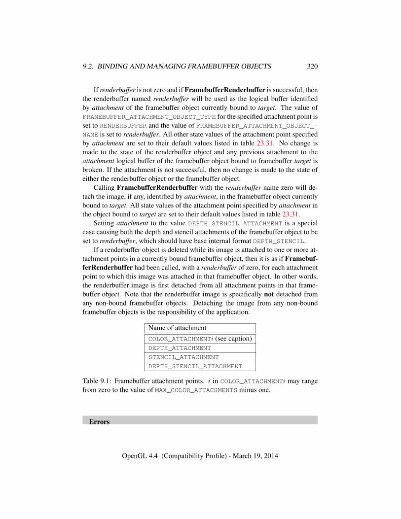
9.2. BINDING AND MANAGING FRAMEBUFFER OBJECTS 320
If renderbuffer is not zero and if FramebufferRenderbuffer is successful, thenthe renderbuffer named renderbuffer will be used as the logical buffer identifiedby attachment of the framebuffer object currently bound to target. The value ofFRAMEBUFFER_ATTACHMENT_OBJECT_TYPE for the specified attachment point isset to RENDERBUFFER and the value of FRAMEBUFFER_ATTACHMENT_OBJECT_-NAME is set to renderbuffer. All other state values of the attachment point specifiedby attachment are set to their default values listed in table 23.31. No change ismade to the state of the renderbuffer object and any previous attachment to theattachment logical buffer of the framebuffer object bound to framebuffer target isbroken. If the attachment is not successful, then no change is made to the state ofeither the renderbuffer object or the framebuffer object.
Calling FramebufferRenderbuffer with the renderbuffer name zero will de-tach the image, if any, identified by attachment, in the framebuffer object currentlybound to target. All state values of the attachment point specified by attachment inthe object bound to target are set to their default values listed in table 23.31.
Setting attachment to the value DEPTH_STENCIL_ATTACHMENT is a specialcase causing both the depth and stencil attachments of the framebuffer object to beset to renderbuffer, which should have base internal format DEPTH_STENCIL.
If a renderbuffer object is deleted while its image is attached to one or more at-tachment points in a currently bound framebuffer object, then it is as if Framebuf-ferRenderbuffer had been called, with a renderbuffer of zero, for each attachmentpoint to which this image was attached in that framebuffer object. In other words,the renderbuffer image is first detached from all attachment points in that frame-buffer object. Note that the renderbuffer image is specifically not detached fromany non-bound framebuffer objects. Detaching the image from any non-boundframebuffer objects is the responsibility of the application.
Name of attachmentCOLOR_ATTACHMENTi (see caption)DEPTH_ATTACHMENT
STENCIL_ATTACHMENT
DEPTH_STENCIL_ATTACHMENT
Table 9.1: Framebuffer attachment points. i in COLOR_ATTACHMENTi may rangefrom zero to the value of MAX_COLOR_ATTACHMENTS minus one.
Errors
OpenGL 4.4 (Compatibility Profile) - March 19, 2014
9.2. BINDING AND MANAGING FRAMEBUFFER OBJECTS 321
An INVALID_ENUM error is generated if target is not DRAW_-
FRAMEBUFFER, READ_FRAMEBUFFER, or FRAMEBUFFER.An INVALID_ENUM error is generated if attachment is not one of the at-
tachment points in table 9.1.An INVALID_ENUM error is generated if renderbuffertarget is not
RENDERBUFFER.An INVALID_OPERATION error is generated if renderbuffer is not zero or
the name of an existing renderbuffer object of type renderbuffertarget.An INVALID_OPERATION error is generated if zero is bound to target.
9.2.8 Attaching Texture Images to a Framebuffer
The GL supports copying the rendered contents of the framebuffer into the imagesof a texture object through the use of the routines CopyTexImage* and CopyTex-SubImage*. Additionally, the GL supports rendering directly into the images of atexture object.
To render directly into a texture image, a specified level of a texture object canbe attached as one of the logical buffers of the currently bound framebuffer objectby calling:
void FramebufferTexture( enum target, enum attachment,uint texture, int level );
target must be DRAW_FRAMEBUFFER, READ_FRAMEBUFFER,or FRAMEBUFFER. FRAMEBUFFER is equivalent to DRAW_FRAMEBUFFER. attach-ment must be one of the attachment points of the framebuffer listed in table 9.1.
If texture is non-zero, the specified mipmap level of the texture object namedtexture is attached to the framebuffer attachment point named by attachment.
If texture is the name of a three-dimensional texture, cube map texture, one-ortwo-dimensional array texture, or two-dimensional multisample array texture, thetexture level attached to the framebuffer attachment point is an array of images,and the framebuffer attachment is considered layered.
Errors
An INVALID_ENUM error is generated if target is not DRAW_-
FRAMEBUFFER, READ_FRAMEBUFFER, or FRAMEBUFFER.An INVALID_ENUM error is generated if attachment is not one of the at-
tachments in table 9.1.An INVALID_OPERATION error is generated if zero is bound to target.An INVALID_VALUE error is generated if texture is not the name of a
OpenGL 4.4 (Compatibility Profile) - March 19, 2014
9.2. BINDING AND MANAGING FRAMEBUFFER OBJECTS 322
texture object, or if level is not a supported texture level for texture.An INVALID_OPERATION error is generated if texture is the name of a
buffer texture.
Additionally, a specified image from a texture object can be attached as one ofthe logical buffers of a currently bound framebuffer object by calling one of thefollowing routines, depending on the type of the texture:
void FramebufferTexture1D( enum target, enum attachment,enum textarget, uint texture, int level );
void FramebufferTexture2D( enum target, enum attachment,enum textarget, uint texture, int level );
void FramebufferTexture3D( enum target, enum attachment,enum textarget, uint texture, int level, int layer );
In all three routines, target must be DRAW_FRAMEBUFFER, READ_-
FRAMEBUFFER, or FRAMEBUFFER. FRAMEBUFFER is equivalent to DRAW_-
FRAMEBUFFER. attachment must be one of the attachment points of the framebufferlisted in table 9.1.
If texture is not zero, then texture must either name an existing texture objectwith an target of textarget, or texture must name an existing cube map texture andtextarget must be one of the cube map face targets from table 8.26.
level specifies the mipmap level of the texture image to be attached to theframebuffer.
If textarget is TEXTURE_RECTANGLE or TEXTURE_2D_MULTISAMPLE, thenlevel must be zero. If textarget is TEXTURE_3D, then level must be greater than orequal to zero and less than or equal to log2 of the value of MAX_3D_TEXTURE_-SIZE. If textarget is one of the cube map face targets from table 8.26, then levelmust be greater than or equal to zero and less than or equal to log2 of the valueof MAX_CUBE_MAP_TEXTURE_SIZE. For all other values of textarget, level mustbe greater than or equal to zero and no larger than log2 of the value of MAX_-TEXTURE_SIZE.
layer specifies the layer of a two-dimensional image within a three-dimensionaltexture.
Errors
An INVALID_ENUM error is generated if target is not DRAW_-
FRAMEBUFFER, READ_FRAMEBUFFER, or FRAMEBUFFER.An INVALID_ENUM error is generated if attachment is not one of the at-
tachments in table 9.1.
OpenGL 4.4 (Compatibility Profile) - March 19, 2014
9.2. BINDING AND MANAGING FRAMEBUFFER OBJECTS 323
An INVALID_OPERATION error is generated if zero is bound to target.An INVALID_VALUE error is generated if texture is not zero and level is
not a supported texture level for textarget, as described above.An INVALID_VALUE error is generated if texture is not zero and layer is
larger than the value of MAX_3D_TEXTURE_SIZE minus one.An INVALID_OPERATION error is generated for FramebufferTexture1D
if texture is not zero and textarget is not TEXTURE_1D.An INVALID_OPERATION error is generated for FramebufferTexture2D
if texture is not zero and textarget is not one of TEXTURE_2D, TEXTURE_2D_-MULTISAMPLE, TEXTURE_RECTANGLE, or one of the cube map face targetsfrom table 8.26.
An INVALID_OPERATION error is generated for FramebufferTexture3Dif texture is not zero and textarget is not TEXTURE_3D.
An INVALID_OPERATION error is generated if texture is not zero, anddoes not name an existing texture object of type matching textarget, as de-scribed above.
An INVALID_OPERATION error is generated if texture is the name of abuffer texture.
The command
void FramebufferTextureLayer( enum target,enum attachment, uint texture, int level, int layer );
operates identically to FramebufferTexture3D, except that it attaches a singlelayer of a three-dimensional, one-or two-dimensional array, cube map array, ortwo-dimensional multisample array texture level.
layer specifies the layer of a two-dimensional image within texture except forcube map array textures, where layer is translated into an array layer and a cubemap face as described for layer-face numbers in section 8.5.3.
If texture is a three-dimensional texture, then level must be greater than or equalto zero and less than or equal to log2 of the value of MAX_3D_TEXTURE_SIZE. Iftexture is a two-dimensional array texture, then level must be greater than or equalto zero and no larger than log2 of the value of MAX_TEXTURE_SIZE.
Errors
An INVALID_VALUE error is generated if layer is larger than the value ofMAX_3D_TEXTURE_SIZE minus one (for three-dimensional textures) or largerthan the value of MAX_ARRAY_TEXTURE_LAYERS minus one (for array tex-tures).
OpenGL 4.4 (Compatibility Profile) - March 19, 2014
9.2. BINDING AND MANAGING FRAMEBUFFER OBJECTS 324
An INVALID_VALUE error is generated if texture is non-zero and layer isnegative.
An INVALID_OPERATION error is generated if texture is non-zero andis not the name of a three-dimensional, two-dimensional multisample array,one-or two-dimensional array, or cube map array texture.
An INVALID_VALUE error is generated if texture is not zero and level isnot a supported texture level for texture, as described above.
Unlike FramebufferTexture3D, no textarget parameter is accepted.If texture is non-zero and the command does not result in an error, the
framebuffer attachment state corresponding to attachment is updated as in theother FramebufferTexture commands, except that the value of FRAMEBUFFER_-ATTACHMENT_TEXTURE_LAYER is set to layer.
9.2.8.1 Effects of Attaching a Texture Image
The remaining comments in this section apply to all forms of FramebufferTex-ture*.
If texture is zero, any image or array of images attached to the attachment pointnamed by attachment is detached. Any additional parameters (level, textarget,and/or layer) are ignored when texture is zero. All state values of the attachmentpoint specified by attachment are set to their default values listed in table 23.31.
If texture is not zero, and if FramebufferTexture* is successful, then the spec-ified texture image will be used as the logical buffer identified by attachment of theframebuffer object currently bound to target. State values of the specified attach-ment point are set as follows:
• The value of FRAMEBUFFER_ATTACHMENT_OBJECT_TYPE is set toTEXTURE.
• The value of FRAMEBUFFER_ATTACHMENT_OBJECT_NAME is set to texture.
• The value of FRAMEBUFFER_ATTACHMENT_TEXTURE_LEVEL is set to level.
• If FramebufferTexture2D is called and texture is a cube map texture, thenthe value of FRAMEBUFFER_ATTACHMENT_TEXTURE_CUBE_MAP_FACE isset to textarget; otherwise it is set to the default value (NONE).
• If FramebufferTextureLayer or FramebufferTexture3D is called, thenthe value of FRAMEBUFFER_ATTACHMENT_TEXTURE_LAYER is set to layer;otherwise it is set to zero.
OpenGL 4.4 (Compatibility Profile) - March 19, 2014
9.3. FEEDBACK LOOPS BETWEEN TEXTURES AND THE FRAMEBUFFER325
• If FramebufferTexture is called and texture is the name of a three-dimensional, cube map, two-dimensional multisample array, or one-or two-dimensional array texture, the value of FRAMEBUFFER_ATTACHMENT_-
LAYERED is set to TRUE; otherwise it is set to FALSE.
All other state values of the attachment point specified by attachment are setto their default values listed in table 23.31. No change is made to the state of thetexture object, and any previous attachment to the attachment logical buffer of theframebuffer object bound to framebuffer target is broken. If the attachment is notsuccessful, then no change is made to the state of either the texture object or theframebuffer object.
Setting attachment to the value DEPTH_STENCIL_ATTACHMENT is a specialcase causing both the depth and stencil attachments of the framebuffer object tobe set to texture. texture must have base internal format DEPTH_STENCIL, or thedepth and stencil framebuffer attachments will be incomplete (see section 9.4.1).
If a texture object is deleted while its image is attached to one or more at-tachment points in a currently bound framebuffer object, then it is as if Frame-bufferTexture* had been called, with a texture of zero, for each attachment pointto which this image was attached in that framebuffer object. In other words, thetexture image is first detached from all attachment points in that framebuffer ob-ject. Note that the texture image is specifically not detached from any non-boundframebuffer objects. Detaching the texture image from any non-bound framebufferobjects is the responsibility of the application.
9.3 Feedback Loops Between Textures and the Frame-buffer
A feedback loop may exist when a texture object is used as both the source anddestination of a GL operation. When a feedback loop exists, undefined behaviorresults. This section describes rendering feedback loops (see section 8.14.2.1) andtexture copying feedback loops (see section 8.6.1) in more detail.
9.3.1 Rendering Feedback Loops
The mechanisms for attaching textures to a framebuffer object do not prevent aone-or two-dimensional texture level, a face of a cube map texture level, or a layerof a two-dimensional array or three-dimensional texture from being attached tothe draw framebuffer while the same texture is bound to a texture unit. Whilethis condition holds, texturing operations accessing that image will produce unde-fined results, as described at the end of section 8.14. Conditions resulting in such
OpenGL 4.4 (Compatibility Profile) - March 19, 2014
9.3. FEEDBACK LOOPS BETWEEN TEXTURES AND THE FRAMEBUFFER326
undefined behavior are defined in more detail below. Such undefined texturing op-erations are likely to leave the final results of the shader or fixed-function fragmentprocessing operations undefined, and should be avoided.
Special precautions need to be taken to avoid attaching a texture image to thecurrently bound draw framebuffer object while the texture object is currently boundand enabled for texturing. Doing so could lead to the creation of a rendering feed-back loop between the writing of pixels by GL rendering operations and the simul-taneous reading of those same pixels when used as texels in the currently boundtexture. In this scenario, the framebuffer will be considered framebuffer complete(see section 9.4), but the values of fragments rendered while in this state will beundefined. The values of texture samples may be undefined as well, as describedunder “Rendering Feedback Loops” in section 8.14.2.1
Specifically, the values of rendered fragments are undefined if all of the fol-lowing conditions are true:
• an image from texture object T is attached to the currently bound draw frame-buffer object at attachment point A
• the texture object T is currently bound to a texture unit U, and
• the current fixed-function texture state or programmable vertex and/or frag-ment processing state makes it possible (see below) to sample from the tex-ture object T bound to texture unit U
while either of the following conditions are true:
• the value of TEXTURE_MIN_FILTER for texture object T is NEAREST orLINEAR, and the value of FRAMEBUFFER_ATTACHMENT_TEXTURE_LEVELfor attachment point A is equal to the value of TEXTURE_BASE_LEVEL forthe texture object T
• the value of TEXTURE_MIN_FILTER for texture object T is oneof NEAREST_MIPMAP_NEAREST, NEAREST_MIPMAP_LINEAR, LINEAR_-MIPMAP_NEAREST, or LINEAR_MIPMAP_LINEAR, and the value ofFRAMEBUFFER_ATTACHMENT_TEXTURE_LEVEL for attachment point A iswithin the range specified by the current values of TEXTURE_BASE_LEVELto q, inclusive, for the texture object T. q is defined in section 8.14.3.
For the purpose of this discussion, it is possible to sample from the textureobject T bound to texture unit U if any of the following are true:
OpenGL 4.4 (Compatibility Profile) - March 19, 2014
9.4. FRAMEBUFFER COMPLETENESS 327
• Programmable fragment processing is disabled and the target of texture ob-ject T is enabled according to the texture target precedence rules of sec-tion 16.2
• The active fragment or vertex shader contains any instructions that mightsample from the texture object T bound to U, even if those instructions mightonly be executed conditionally.
Note that if TEXTURE_BASE_LEVEL and TEXTURE_MAX_LEVEL exclude anylevels containing image(s) attached to the currently bound draw framebuffer object,then the above conditions will not be met (i.e., the above rule will not cause thevalues of rendered fragments to be undefined.)
9.3.2 Texture Copying Feedback Loops
Similarly to rendering feedback loops, it is possible for a texture image to be at-tached to the currently bound read framebuffer object while the same texture im-age is the destination of a CopyTexImage* operation, as described under “TextureCopying Feedback Loops” in section 8.6.1. While this condition holds, a texturecopying feedback loop between the writing of texels by the copying operation andthe reading of those same texels when used as pixels in the read framebuffer mayexist. In this scenario, the values of texels written by the copying operation will beundefined (in the same fashion that overlapping copies via BlitFramebuffer areundefined).
Specifically, the values of copied texels are undefined if all of the followingconditions are true:
• an image from texture object T is attached to the currently bound read frame-buffer object at attachment point A
• the selected read buffer (see section 18.2.1) is attachment point A
• T is bound to the texture target of a CopyTexImage* operation
• the level argument of the copying operation selects the same image that isattached to A
9.4 Framebuffer Completeness
A framebuffer must be framebuffer complete to effectively be used as the draw orread framebuffer of the GL.
OpenGL 4.4 (Compatibility Profile) - March 19, 2014
9.4. FRAMEBUFFER COMPLETENESS 328
The default framebuffer is always complete if it exists; however, if no defaultframebuffer exists (no window system-provided drawable is associated with theGL context), it is deemed to be incomplete.
A framebuffer object is said to be framebuffer complete if all of its attachedimages, and all framebuffer parameters required to utilize the framebuffer for ren-dering and reading, are consistently defined and meet the requirements definedbelow. The rules of framebuffer completeness are dependent on the properties ofthe attached images, and on certain implementation-dependent restrictions.
The internal formats of the attached images can affect the completeness ofthe framebuffer, so it is useful to first define the relationship between the internalformat of an image and the attachment points to which it can be attached.
• An internal format is color-renderable if it is ALPHA, RED, RG, RGB, RGBA,or one of the sized internal formats from table 8.19 whose “CR” (color-renderable) column is checked in that table No other formats, includingcompressed internal formats, are color-renderable.
• An internal format is depth-renderable if it is DEPTH_COMPONENT or oneof the formats from table 8.21 whose base internal format is DEPTH_-
COMPONENT or DEPTH_STENCIL. No other formats are depth-renderable.
• An internal format is stencil-renderable if it is STENCIL_INDEX, DEPTH_-STENCIL, or one of the formats from table 8.21 whose base internal for-mat is STENCIL_INDEX or DEPTH_STENCIL. No other formats are stencil-renderable.
9.4.1 Framebuffer Attachment Completeness
If the value of FRAMEBUFFER_ATTACHMENT_OBJECT_TYPE for the framebufferattachment point attachment is not NONE, then it is said that a framebuffer-attachable image, named image, is attached to the framebuffer at the attachmentpoint. image is identified by the state in attachment as described in section 9.2.2.
The framebuffer attachment point attachment is said to be framebuffer attach-ment complete if the value of FRAMEBUFFER_ATTACHMENT_OBJECT_TYPE forattachment is NONE (i.e., no image is attached), or if all of the following conditionsare true:
• image is a component of an existing object with the name specified bythe value of FRAMEBUFFER_ATTACHMENT_OBJECT_NAME, and of the typespecified by the value of FRAMEBUFFER_ATTACHMENT_OBJECT_TYPE.
OpenGL 4.4 (Compatibility Profile) - March 19, 2014
9.4. FRAMEBUFFER COMPLETENESS 329
• The width and height of image are greater than zero and less than or equalto the values of the implementation-dependent limits MAX_FRAMEBUFFER_-WIDTH and MAX_FRAMEBUFFER_HEIGHT, respectively.
• If image is a three-dimensional texture or a one-or two-dimensional arraytexture and the attachment is not layered, the selected layer is less than thedepth or layer count of the texture.
• If image is a three-dimensional texture or a one-or two-dimensional arraytexture and the attachment is layered, the depth or layer count of the texture isless than or equal to the value of the implementation-dependent limit MAX_-FRAMEBUFFER_LAYERS.
• If image has multiple samples, its sample count is less than or equal tothe value of the implementation-dependent limit MAX_FRAMEBUFFER_-
SAMPLES.
• If image is a non-immutable format texture, the selected level number is inthe range [levelbase, q], where levelbase and q are as defined in section 8.14.3.
• If image is a non-immutable format texture and the selected level is notlevelbase, the texture must be mipmap complete; if image is part of a cube-map texture, the texture must also be mipmap cube complete.
• If attachment is COLOR_ATTACHMENTi, then image must have a color-renderable internal format.
• If attachment is DEPTH_ATTACHMENT, then image must have a depth-renderable internal format.
• If attachment is STENCIL_ATTACHMENT, then image must have a stencil-renderable internal format.
9.4.2 Whole Framebuffer Completeness
Each rule below is followed by an error token enclosed in { brackets }. The mean-ing of these errors is explained below and under “Effects of Framebuffer Com-pleteness on Framebuffer Operations” in section 9.4.4.
The framebuffer object target is said to be framebuffer complete if all the fol-lowing conditions are true:
• if target is the default framebuffer, the default framebuffer exists.
{ FRAMEBUFFER_UNDEFINED }
OpenGL 4.4 (Compatibility Profile) - March 19, 2014
9.4. FRAMEBUFFER COMPLETENESS 330
• All framebuffer attachment points are framebuffer attachment complete.
{ FRAMEBUFFER_INCOMPLETE_ATTACHMENT }
• There is at least one image attached to the framebuffer, or the value ofthe framebuffer’s FRAMEBUFFER_DEFAULT_WIDTH and FRAMEBUFFER_-
DEFAULT_HEIGHT parameters are both non-zero.
{ FRAMEBUFFER_INCOMPLETE_MISSING_ATTACHMENT }
• The combination of internal formats of the attached images does not violatean implementation-dependent set of restrictions.
{ FRAMEBUFFER_UNSUPPORTED }
• The value of RENDERBUFFER_SAMPLES is the same for all attached render-buffers; the value of TEXTURE_SAMPLES is the same for all attached tex-tures; and, if the attached images are a mix of renderbuffers and textures,the value of RENDERBUFFER_SAMPLES matches the value of TEXTURE_-SAMPLES.
{ FRAMEBUFFER_INCOMPLETE_MULTISAMPLE }
• The value of TEXTURE_FIXED_SAMPLE_LOCATIONS is the same for allattached textures; and, if the attached images are a mix of renderbuffersand textures, the value of TEXTURE_FIXED_SAMPLE_LOCATIONS must beTRUE for all attached textures.
{ FRAMEBUFFER_INCOMPLETE_MULTISAMPLE }
• If any framebuffer attachment is layered, all populated attachments must belayered. Additionally, all populated color attachments must be from texturesof the same target (three-dimensional, one-or two-dimensional array, cubemap, or cube map array textures).
{ FRAMEBUFFER_INCOMPLETE_LAYER_TARGETS }
The token in brackets after each clause of the framebuffer completeness rulesspecifies the return value of CheckFramebufferStatus (see below) that is gen-erated when that clause is violated. If more than one clause is violated, it is
OpenGL 4.4 (Compatibility Profile) - March 19, 2014
9.4. FRAMEBUFFER COMPLETENESS 331
implementation-dependent which value will be returned by CheckFramebuffer-Status.
Performing any of the following actions may change whether the framebufferis considered complete or incomplete:
• Binding to a different framebuffer with BindFramebuffer.
• Attaching an image to the framebuffer with FramebufferTexture* orFramebufferRenderbuffer.
• Detaching an image from the framebuffer with FramebufferTexture* orFramebufferRenderbuffer.
• Changing the internal format of a texture image that is attached to the frame-buffer by calling TexImage*, TexStorage*, CopyTexImage*, or Com-pressedTexImage*.
• Changing the internal format of a renderbuffer that is attached to the frame-buffer by calling RenderbufferStorage*.
• Deleting, with DeleteTextures or DeleteRenderbuffers, an object contain-ing an image that is attached to a currently bound framebuffer object.
• Associating a different window system-provided drawable, or no drawable,with the default framebuffer using a window system binding API such asthose described in section 1.3.5.
Although the GL defines a wide variety of internal formats for framebuffer-attachable images, such as texture images and renderbuffer images, some imple-mentations may not support rendering to particular combinations of internal for-mats. If the combination of formats of the images attached to a framebuffer objectare not supported by the implementation, then the framebuffer is not complete un-der the clause labeled FRAMEBUFFER_UNSUPPORTED.
Implementations are required to support certain combinations of framebufferinternal formats as described under “Required Framebuffer Formats” in sec-tion 9.4.3.
Because of the implementation-dependent clause of the framebuffer complete-ness test in particular, and because framebuffer completeness can change when theset of attached images is modified, it is strongly advised, though not required, thatan application check to see if the framebuffer is complete prior to rendering. Thestatus of the framebuffer object currently bound to target can be queried by calling
enum CheckFramebufferStatus( enum target );
OpenGL 4.4 (Compatibility Profile) - March 19, 2014
9.4. FRAMEBUFFER COMPLETENESS 332
target must be DRAW_FRAMEBUFFER, READ_FRAMEBUFFER, orFRAMEBUFFER. FRAMEBUFFER is equivalent to DRAW_FRAMEBUFFER.
A value is returned that identifies whether or not the framebuffer object boundto target is complete, and if not complete the value identifies one of the rules offramebuffer completeness that is violated. If the framebuffer object is complete,then FRAMEBUFFER_COMPLETE is returned.
The values of SAMPLE_BUFFERS and SAMPLES are derived from the attach-ments of the currently bound draw framebuffer object. If the current DRAW_-FRAMEBUFFER_BINDING is not framebuffer complete, then both SAMPLE_-
BUFFERS and SAMPLES are undefined. Otherwise, SAMPLES is equal to the valueof RENDERBUFFER_SAMPLES or TEXTURE_SAMPLES (depending on the type ofthe attached images), which must all have the same value. Further, SAMPLE_-BUFFERS is one if SAMPLES is non-zero. Otherwise, SAMPLE_BUFFERS is zero.
If CheckFramebufferStatus generates an error, zero is returned.
Errors
An INVALID_ENUM error is generated if target is not DRAW_-
FRAMEBUFFER, READ_FRAMEBUFFER, or FRAMEBUFFER.
9.4.3 Required Framebuffer Formats
Implementations must support framebuffer objects with up to MAX_COLOR_-
ATTACHMENTS color attachments, a depth attachment, and a stencil attachment.Each color attachment may be in any of the color-renderable formats describedin section 9.4 (although implementations are not required to support creation ofattachments in all color-renderable formats). The depth attachment may be inany of the required depth or combined depth+stencil formats described in sec-tions 8.5.1 and 9.2.5, and the stencil attachment may be in any of the requiredstencil or combined depth+stencil formats. However, when both depth and stencilattachments are present, implementations are only required to support framebufferobjects where both attachments refer to the same image.
There must be at least one default framebuffer format allowing creation of adefault framebuffer supporting front-buffered rendering.
9.4.4 Effects of Framebuffer Completeness on Framebuffer Opera-tions
An INVALID_FRAMEBUFFER_OPERATION error is generated by attempts to renderto or read from a framebuffer which is not framebuffer complete. This error is
OpenGL 4.4 (Compatibility Profile) - March 19, 2014
9.4. FRAMEBUFFER COMPLETENESS 333
generated regardless of whether fragments are actually read from or written to theframebuffer. For example, it is generated when a rendering command is called andthe framebuffer is incomplete, even if RASTERIZER_DISCARD is enabled.
Errors
An INVALID_FRAMEBUFFER_OPERATION error is generated by render-ing commands (see section 2.4), RasterPos, and commands that read from theframebuffer such as ReadPixels, CopyTexImage*, and CopyTexSubImage*if called while the framebuffer is not framebuffer complete.
9.4.5 Effects of Framebuffer State on Framebuffer Dependent Values
The values of the state variables listed in table 23.85 may change when a change ismade to DRAW_FRAMEBUFFER_BINDING, to the state of the currently bound drawframebuffer object, or to an image attached to that framebuffer object.
When DRAW_FRAMEBUFFER_BINDING is zero, the values of the state variableslisted in table 23.85 are implementation defined.
When DRAW_FRAMEBUFFER_BINDING is non-zero, if the currently bounddraw framebuffer object is not framebuffer complete, then the values of the statevariables listed in table 23.85 are undefined.
When DRAW_FRAMEBUFFER_BINDING is non-zero and the currently bounddraw framebuffer object is framebuffer complete, then the values of the state vari-ables listed in table 23.85 are completely determined by DRAW_FRAMEBUFFER_-
BINDING, the state of the currently bound draw framebuffer object, and the state ofthe images attached to that framebuffer object. The values of RED_BITS, GREEN_-BITS, BLUE_BITS, and ALPHA_BITS are defined only if all color attachments ofthe draw framebuffer have identical formats, in which case the color componentdepths of color attachment zero are returned. The values returned for DEPTH_BITSand STENCIL_BITS are the depth or stencil component depth of the correspondingattachment of the draw framebuffer, respectively.
The actual sizes of the color, depth, or stencil bit planes can be obtained byquerying an attachment point using GetFramebufferAttachmentParameteriv,or querying the object attached to that point. If the value of FRAMEBUFFER_-ATTACHMENT_OBJECT_TYPE at a particular attachment point is RENDERBUFFER,the sizes may be determined by calling GetRenderbufferParameteriv as de-scribed in section 9.2.6. If the value of FRAMEBUFFER_ATTACHMENT_OBJECT_-TYPE at a particular attachment point is TEXTURE, the sizes may be determined bycalling GetTexParameter, as described in section 8.11.
OpenGL 4.4 (Compatibility Profile) - March 19, 2014
9.5. MAPPING BETWEEN PIXEL AND ELEMENT IN ATTACHED IMAGE334
9.5 Mapping between Pixel and Element in Attached Im-age
When DRAW_FRAMEBUFFER_BINDING is non-zero, an operation that writes to theframebuffer modifies the image attached to the selected logical buffer, and an oper-ation that reads from the framebuffer reads from the image attached to the selectedlogical buffer.
If the attached image is a renderbuffer image, then the window coordinates(xw, yw) corresponds to the value in the renderbuffer image at the same coordi-nates.
If the attached image is a texture image, then the window coordinates (xw, yw)correspond to the texel (i, j, k) from figure 8.3 as follows:
i = (xw − b)
j = (yw − b)
k = (layer − b)
where b is the texture image’s border width and layer is the value ofFRAMEBUFFER_ATTACHMENT_TEXTURE_LAYER for the selected logical buffer.For a two-dimensional texture, k and layer are irrelevant; for a one-dimensionaltexture, j, k, and layer are irrelevant.
(xw, yw) corresponds to a border texel if xw, yw, or layer is less than the borderwidth, or if xw, yw, or layer is greater than or equal to the border width plus thewidth, height, or depth, respectively, of the texture image.
9.6 Conversion to Framebuffer-Attachable Image Com-ponents
When an enabled color value is written to the framebuffer while the draw frame-buffer binding is non-zero, for each draw buffer the R, G, B, and A values areconverted to internal components as described in table 8.18, according to the ta-ble row corresponding to the internal format of the framebuffer-attachable imageattached to the selected logical buffer, and the resulting internal components arewritten to the image attached to logical buffer. The masking operations describedin section 17.4.2 are also effective.
OpenGL 4.4 (Compatibility Profile) - March 19, 2014
9.7. CONVERSION TO RGBA VALUES 335
9.7 Conversion to RGBA Values
When a color value is read while the read framebuffer binding is non-zero, or isused as the source of a logical operation or for blending while the draw frame-buffer binding is non-zero, components of that color taken from the framebuffer-attachable image attached to the selected logical buffer are first converted to R,G, B, and A values according to table 16.1 and the internal format of the attachedimage.
9.8 Layered Framebuffers
A framebuffer is considered to be layered if it is complete and all of its populatedattachments are layered. When rendering to a layered framebuffer, each fragmentgenerated by the GL is assigned a layer number. The layer number for a fragmentis zero if
• the fragment is generated by DrawPixels, CopyPixels, or Bitmap,
• geometry shaders are disabled, or
• the current geometry shader does not statically assign a value to the built-inoutput variable gl_Layer.
Otherwise, the layer for each point, line, or triangle emitted by the geometryshader is taken from the gl_Layer output of one of the vertices of the primitive.The vertex used is implementation-dependent. To get defined results, all verticesof each primitive emitted should set the same value for gl_Layer. Since theEndPrimitive built-in function starts a new output primitive, defined results canbe achieved if EndPrimitive is called between two vertices emitted with differ-ent layer numbers. A layer number written by a geometry shader has no effect ifthe framebuffer is not layered.
When fragments are written to a layered framebuffer, the fragment’s layer num-ber selects an image from the array of images at each attachment point to use forthe stencil test (see section 17.3.5), depth buffer test (see section 17.3.6), and forblending and color buffer writes (see section 17.3.8). If the fragment’s layer num-ber is negative, or greater than or equal to the minimum number of layers of anyattachment, the effects of the fragment on the framebuffer contents are undefined.
When the Clear or ClearBuffer* commands described in section 17.4.3 areused to clear a layered framebuffer attachment, all layers of the attachment arecleared.
OpenGL 4.4 (Compatibility Profile) - March 19, 2014
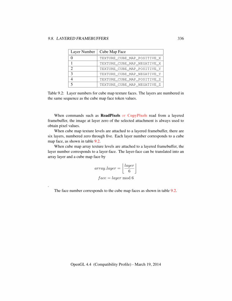
9.8. LAYERED FRAMEBUFFERS 336
Layer Number Cube Map Face0 TEXTURE_CUBE_MAP_POSITIVE_X
1 TEXTURE_CUBE_MAP_NEGATIVE_X
2 TEXTURE_CUBE_MAP_POSITIVE_Y
3 TEXTURE_CUBE_MAP_NEGATIVE_Y
4 TEXTURE_CUBE_MAP_POSITIVE_Z
5 TEXTURE_CUBE_MAP_NEGATIVE_Z
Table 9.2: Layer numbers for cube map texture faces. The layers are numbered inthe same sequence as the cube map face token values.
When commands such as ReadPixels or CopyPixels read from a layeredframebuffer, the image at layer zero of the selected attachment is always used toobtain pixel values.
When cube map texture levels are attached to a layered framebuffer, there aresix layers, numbered zero through five. Each layer number corresponds to a cubemap face, as shown in table 9.2.
When cube map array texture levels are attached to a layered framebuffer, thelayer number corresponds to a layer-face. The layer-face can be translated into anarray layer and a cube map face by
array layer =
⌊layer
6
⌋face = layer mod 6
.The face number corresponds to the cube map faces as shown in table 9.2.
OpenGL 4.4 (Compatibility Profile) - March 19, 2014
Chapter 10
Vertex Specification and DrawingCommands
Most geometric primitives are drawn by specifying a series of generic attributesets corresponding to vertices of a primitive using DrawArrays or one of the otherdrawing commands defined in section 10.5. Points, lines, polygons, and a varietyof related geometric primitives (see section 10.1) can be drawn in this way.
Alternatively, non-generic attributes of vertices such as vertex coordinates, nor-mals, texture coordinates, and vertex colors may be specified for use by shaders orby fixed-function vertex processing functionality.
Geometric objects may also be drawn by specifying attributes between Begin /End pairs as described in section 10.8.
The process of specifying attributes of a vertex and passing them to fixed-function vertex processing or a shader is referred to as transferring a vertex to theGL.
Vertex Shader Processing and Vertex StateEach vertex is specified with one or more generic vertex attributes. Each at-
tribute is specified with one, two, three, or four scalar values.Generic vertex attributes can be accessed from within vertex shaders (see sec-
tion 11.1) and used to compute values for consumption by later processing stages.Before vertex shader execution, the state required by a vertex is its generic
vertex attributes. Vertex shader execution processes vertices producing a homoge-neous vertex position and any outputs explicitly written by the vertex shader.
Figure 10.1 shows the sequence of operations that builds a primitive (point, linesegment, or polygon) from a sequence of vertices. After a primitive is formed, it isclipped to a clip volume. This may modify the primitive by altering vertex coordi-
337
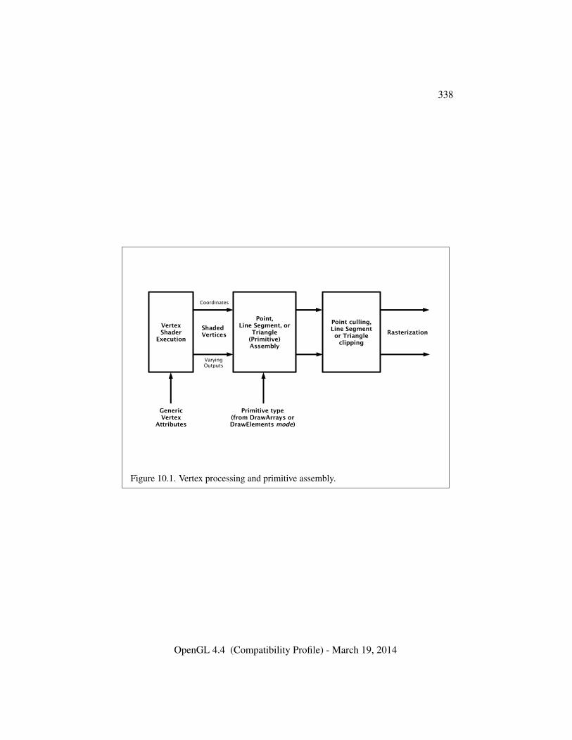
338
Point,Line Segment, or
Triangle(Primitive)Assembly
Point culling,Line Segmentor Triangle
clipping
RasterizationShadedVertices
Coordinates
VaryingOutputs
Primitive type(from DrawArrays orDrawElements mode)
VertexShader
Execution
GenericVertex
Attributes
Figure 10.1. Vertex processing and primitive assembly.
OpenGL 4.4 (Compatibility Profile) - March 19, 2014
339
nates and vertex shader outputs. In the case of line and polygon primitives, clippingmay insert new vertices into the primitive. The vertices defining a primitive to berasterized have output variables associated with them.
Fixed-Function Vertex Processing and Vertex StateWhen fixed-function vertex processing is performed, each vertex is specified
with two, three, or four scalar vertex coordinates. In addition, a current normal,multiple current texture coordinate sets, multiple current generic vertex attributes,current color, current secondary color, and current fog coordinate may be used inprocessing each vertex.
Normals are used by the GL in lighting calculations; the current normal is athree-dimensional vector that may be set by sending three coordinates that specifyit.
Texture coordinates determine how a texture image is mapped onto a primitivein fixed-function fragment processing. Multiple sets of texture coordinates maybe used to specify how multiple texture images are mapped onto a primitive. Thenumber of texture units supported is implementation-dependent but must be at leasttwo. The number of texture units supported can be queried with the state MAX_-
TEXTURE_UNITS.Primary and secondary colors are associated with each vertex (see sec-
tion 16.3). These associated colors are either based on the current color and currentsecondary color or produced by lighting, depending on whether or not lighting isenabled. Texture and fog coordinates are similarly associated with each vertex.Multiple sets of texture coordinates may be associated with a vertex. Figure 10.2summarizes the association of auxiliary data with a transformed vertex to producea processed vertex.
Current values are part of GL state. Vertices and normals are transformed, col-ors may be affected or replaced by lighting, and texture coordinates are transformedand possibly affected by a texture coordinate generation function. The processingindicated for each current value is applied for each vertex that is sent to the GL.The details of fixed-function vertex processing are discussed later.
Before colors have been assigned to a vertex, the state required by a vertexis the vertex’s coordinates, the current normal, the current edge flag (see sec-tion 10.1.17), the current material properties (see section 12.2.2), the current fogcoordinate, the multiple generic vertex attribute sets, and the multiple current tex-ture coordinate sets. Because color assignment is done vertex-by-vertex, a pro-cessed vertex comprises the vertex’s coordinates, its edge flag, its fog coordinate,its assigned colors, and its multiple texture coordinate sets.
Figure 10.3 shows the sequence of operations that builds a primitive (point,line segment, or polygon) from a sequence of vertices using using fixed-functin
OpenGL 4.4 (Compatibility Profile) - March 19, 2014
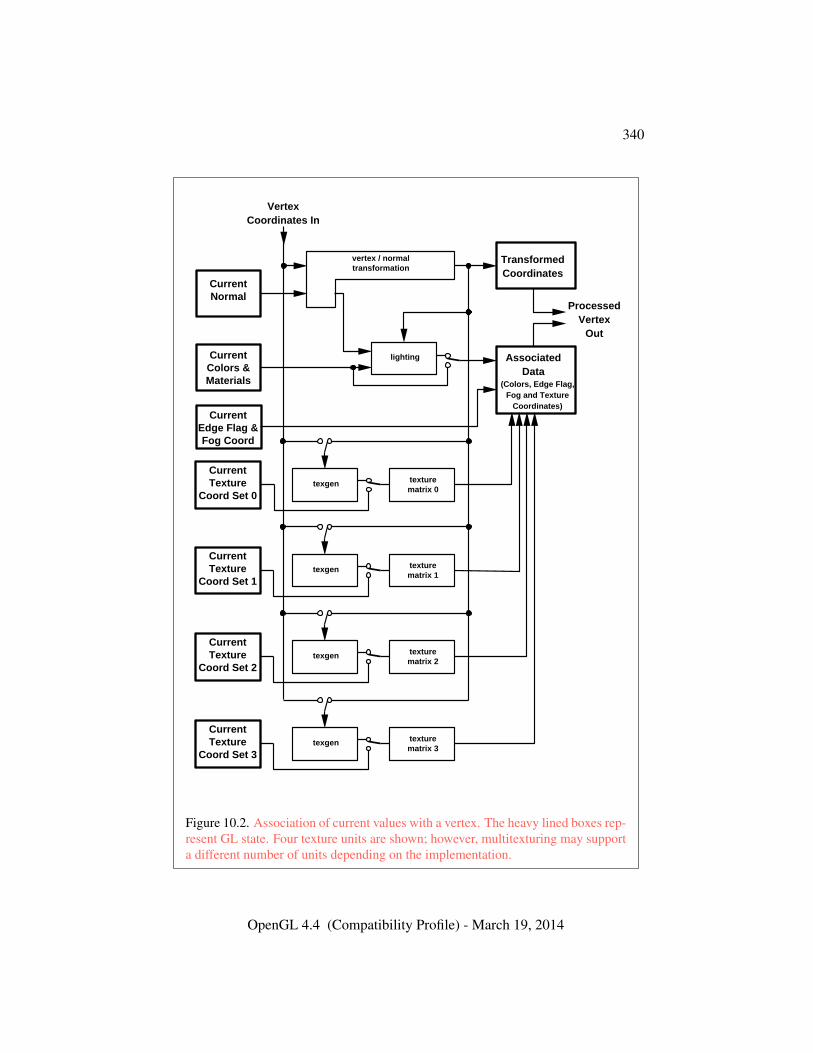
340
CurrentEdge Flag & Fog Coord
lighting
vertex / normaltransformation
CurrentNormal
CurrentColors & Materials
AssociatedData
TransformedCoordinates
ProcessedVertex
Out
(Colors, Edge Flag,Fog and Texture
Coordinates)
VertexCoordinates In
texgen texturematrix 0
CurrentTexture
Coord Set 0
texgen texturematrix 1
CurrentTexture
Coord Set 1
texgen texturematrix 2
CurrentTexture
Coord Set 2
texgen texturematrix 3
CurrentTexture
Coord Set 3
Figure 10.2. Association of current values with a vertex. The heavy lined boxes rep-resent GL state. Four texture units are shown; however, multitexturing may supporta different number of units depending on the implementation.
OpenGL 4.4 (Compatibility Profile) - March 19, 2014
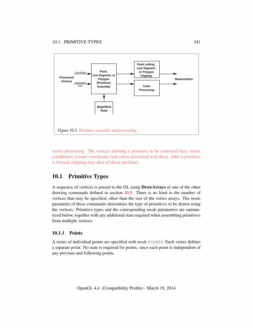
10.1. PRIMITIVE TYPES 341
ProcessedVertices
Point,Line Segment, or
Polygon(Primitive)Assembly
Begin/EndState
Point culling;Line Segment or Polygon
Clipping
ColorProcessing
Rasterization
Coordinates
AssociatedData
Figure 10.3. Primitive assembly and processing.
vertex processing. The vertices defining a primitive to be rasterized have vertexcoordinates, texture coordinates and colors associated with them. After a primitiveis formed, clipping may alter all these attributes.
10.1 Primitive Types
A sequence of vertices is passed to the GL using DrawArrays or one of the otherdrawing commands defined in section 10.5. There is no limit to the number ofvertices that may be specified, other than the size of the vertex arrays. The modeparameter of these commands determines the type of primitives to be drawn usingthe vertices. Primitive types and the corresponding mode parameters are summa-rized below, together with any additional state required when assembling primitivesfrom multiple vertices.
10.1.1 Points
A series of individual points are specified with mode POINTS. Each vertex definesa separate point. No state is required for points, since each point is independent ofany previous and following points.
OpenGL 4.4 (Compatibility Profile) - March 19, 2014
10.1. PRIMITIVE TYPES 342
10.1.2 Line Strips
A series of one or more connected line segments are specified with mode LINE_-STRIP. In this case, the first vertex specifies the first segment’s start point whilethe second vertex specifies the first segment’s endpoint and the second segment’sstart point. In general, the ith vertex (for i > 1) specifies the beginning of the ithsegment and the end of the i − 1st. The last vertex specifies the end of the lastsegment. If only one vertex is specified, then no primitive is generated.
The required state consists of the processed vertex produced from the last ver-tex that was sent (so that a line segment can be generated from it to the currentvertex), and a boolean flag indicating if the current vertex is the first vertex.
10.1.3 Line Loops
A line loop is specified with mode LINE_LOOP. Loops are the same as line stripsexcept that a final segment is added from the final specified vertex to the first vertex.The required state consists of the processed first vertex, in addition to the staterequired for line strips.
10.1.4 Separate Lines
Individual line segments, each defined by a pair of vertices, are specified with modeLINES. The first two vertices passed define the first segment, with subsequent pairsof vertices each defining one more segment. If the number of vertices passed isodd, then the last vertex is ignored. The state required is the same as for line stripsbut it is used differently: a processed vertex holding the first vertex of the currentsegment, and a boolean flag indicating whether the current vertex is odd or even (asegment start or end).
10.1.5 Polygons
A polygon is described by specifying its boundary as a series of line segmentswith mode POLYGON. The bounding line segments are specified in the same way asline loops. A polygon described with fewer than three vertices does not generate aprimitive.
The state required to support polygons consists of at least two processed ver-tices (more than two are never required, although an implementation may usemore); this is because a convex polygon can be rasterized as its vertices arrive,before all of them have been specified.
OpenGL 4.4 (Compatibility Profile) - March 19, 2014
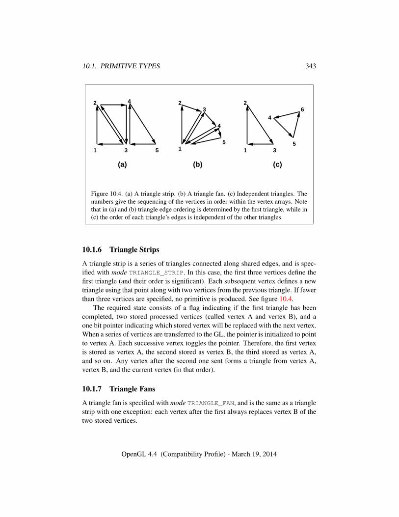
10.1. PRIMITIVE TYPES 343
(a) (b) (c)
1
2
3
4
5 1
23
4
51
2
3
4
5
6
Figure 10.4. (a) A triangle strip. (b) A triangle fan. (c) Independent triangles. Thenumbers give the sequencing of the vertices in order within the vertex arrays. Notethat in (a) and (b) triangle edge ordering is determined by the first triangle, while in(c) the order of each triangle’s edges is independent of the other triangles.
10.1.6 Triangle Strips
A triangle strip is a series of triangles connected along shared edges, and is spec-ified with mode TRIANGLE_STRIP. In this case, the first three vertices define thefirst triangle (and their order is significant). Each subsequent vertex defines a newtriangle using that point along with two vertices from the previous triangle. If fewerthan three vertices are specified, no primitive is produced. See figure 10.4.
The required state consists of a flag indicating if the first triangle has beencompleted, two stored processed vertices (called vertex A and vertex B), and aone bit pointer indicating which stored vertex will be replaced with the next vertex.When a series of vertices are transferred to the GL, the pointer is initialized to pointto vertex A. Each successive vertex toggles the pointer. Therefore, the first vertexis stored as vertex A, the second stored as vertex B, the third stored as vertex A,and so on. Any vertex after the second one sent forms a triangle from vertex A,vertex B, and the current vertex (in that order).
10.1.7 Triangle Fans
A triangle fan is specified with mode TRIANGLE_FAN, and is the same as a trianglestrip with one exception: each vertex after the first always replaces vertex B of thetwo stored vertices.
OpenGL 4.4 (Compatibility Profile) - March 19, 2014
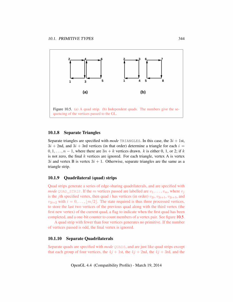
10.1. PRIMITIVE TYPES 344
1
2
3
4
5
6
1
2 3
4 5
6 7
8
(a) (b)
Figure 10.5. (a) A quad strip. (b) Independent quads. The numbers give the se-quencing of the vertices passed to the GL.
10.1.8 Separate Triangles
Separate triangles are specified with mode TRIANGLES. In this case, the 3i + 1st,3i + 2nd, and 3i + 3rd vertices (in that order) determine a triangle for each i =0, 1, . . . , n − 1, where there are 3n + k vertices drawn. k is either 0, 1, or 2; if kis not zero, the final k vertices are ignored. For each triangle, vertex A is vertex3i and vertex B is vertex 3i + 1. Otherwise, separate triangles are the same as atriangle strip.
10.1.9 Quadrilateral (quad) strips
Quad strips generate a series of edge-sharing quadrilaterals, and are specified withmode QUAD_STRIP. If the m vertices passed are labelled are v1, . . . , vm, where vjis the jth specified vertex, then quad i has vertices (in order) v2i, v2i+1, v2i+3, andv2i+2 with i = 0, . . . , bm/2c. The state required is thus three processed vertices,to store the last two vertices of the previous quad along with the third vertex (thefirst new vertex) of the current quad, a flag to indicate when the first quad has beencompleted, and a one-bit counter to count members of a vertex pair. See figure 10.5.
A quad strip with fewer than four vertices generates no primitive. If the numberof vertices passed is odd, the final vertex is ignored.
10.1.10 Separate Quadrilaterals
Separate quads are specified with mode QUADS, and are just like quad strips exceptthat each group of four vertices, the 4j + 1st, the 4j + 2nd, the 4j + 3rd, and the
OpenGL 4.4 (Compatibility Profile) - March 19, 2014
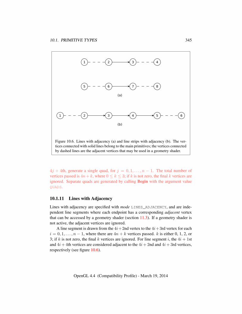
10.1. PRIMITIVE TYPES 345
Figure 10.6. Lines with adjacency (a) and line strips with adjacency (b). The ver-tices connected with solid lines belong to the main primitives; the vertices connectedby dashed lines are the adjacent vertices that may be used in a geometry shader.
4j + 4th, generate a single quad, for j = 0, 1, . . . , n − 1. The total number ofvertices passed is 4n+ k, where 0 ≤ k ≤ 3; if k is not zero, the final k vertices areignored. Separate quads are generated by calling Begin with the argument valueQUADS.
10.1.11 Lines with Adjacency
Lines with adjacency are specified with mode LINES_ADJACENCY, and are inde-pendent line segments where each endpoint has a corresponding adjacent vertexthat can be accessed by a geometry shader (section 11.3). If a geometry shader isnot active, the adjacent vertices are ignored.
A line segment is drawn from the 4i+2nd vertex to the 4i+3rd vertex for eachi = 0, 1, . . . , n − 1, where there are 4n + k vertices passed. k is either 0, 1, 2, or3; if k is not zero, the final k vertices are ignored. For line segment i, the 4i + 1stand 4i+ 4th vertices are considered adjacent to the 4i+ 2nd and 4i+ 3rd vertices,respectively (see figure 10.6).
OpenGL 4.4 (Compatibility Profile) - March 19, 2014
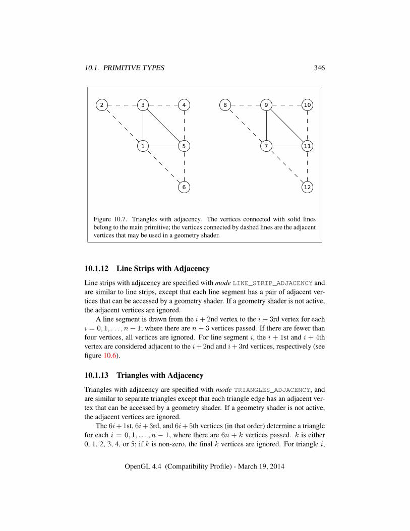
10.1. PRIMITIVE TYPES 346
Figure 10.7. Triangles with adjacency. The vertices connected with solid linesbelong to the main primitive; the vertices connected by dashed lines are the adjacentvertices that may be used in a geometry shader.
10.1.12 Line Strips with Adjacency
Line strips with adjacency are specified with mode LINE_STRIP_ADJACENCY andare similar to line strips, except that each line segment has a pair of adjacent ver-tices that can be accessed by a geometry shader. If a geometry shader is not active,the adjacent vertices are ignored.
A line segment is drawn from the i+ 2nd vertex to the i+ 3rd vertex for eachi = 0, 1, . . . , n − 1, where there are n + 3 vertices passed. If there are fewer thanfour vertices, all vertices are ignored. For line segment i, the i + 1st and i + 4thvertex are considered adjacent to the i+ 2nd and i+ 3rd vertices, respectively (seefigure 10.6).
10.1.13 Triangles with Adjacency
Triangles with adjacency are specified with mode TRIANGLES_ADJACENCY, andare similar to separate triangles except that each triangle edge has an adjacent ver-tex that can be accessed by a geometry shader. If a geometry shader is not active,the adjacent vertices are ignored.
The 6i+ 1st, 6i+ 3rd, and 6i+ 5th vertices (in that order) determine a trianglefor each i = 0, 1, . . . , n − 1, where there are 6n + k vertices passed. k is either0, 1, 2, 3, 4, or 5; if k is non-zero, the final k vertices are ignored. For triangle i,
OpenGL 4.4 (Compatibility Profile) - March 19, 2014
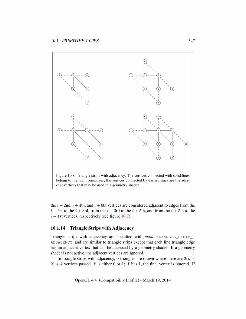
10.1. PRIMITIVE TYPES 347
Figure 10.8. Triangle strips with adjacency. The vertices connected with solid linesbelong to the main primitives; the vertices connected by dashed lines are the adja-cent vertices that may be used in a geometry shader.
the i+ 2nd, i+ 4th, and i+ 6th vertices are considered adjacent to edges from thei + 1st to the i + 3rd, from the i + 3rd to the i + 5th, and from the i + 5th to thei+ 1st vertices, respectively (see figure 10.7).
10.1.14 Triangle Strips with Adjacency
Triangle strips with adjacency are specified with mode TRIANGLE_STRIP_-
ADJACENCY, and are similar to triangle strips except that each line triangle edgehas an adjacent vertex that can be accessed by a geometry shader. If a geometryshader is not active, the adjacent vertices are ignored.
In triangle strips with adjacency, n triangles are drawn where there are 2(n +2) + k vertices passed. k is either 0 or 1; if k is 1, the final vertex is ignored. If
OpenGL 4.4 (Compatibility Profile) - March 19, 2014

10.1. PRIMITIVE TYPES 348
Primitive Vertices Adjacent VerticesPrimitive 1st 2nd 3rd 1/2 2/3 3/1only (i = 0, n = 1) 1 3 5 2 6 4first (i = 0) 1 3 5 2 7 4middle (i odd) 2i+ 3 2i+ 1 2i+ 5 2i− 1 2i+ 4 2i+ 7
middle (i even) 2i+ 1 2i+ 3 2i+ 5 2i− 1 2i+ 7 2i+ 4
last (i = n− 1, i odd) 2i+ 3 2i+ 1 2i+ 5 2i− 1 2i+ 4 2i+ 6
last (i = n− 1, i even) 2i+ 1 2i+ 3 2i+ 5 2i− 1 2i+ 6 2i+ 4
Table 10.1: Triangles generated by triangle strips with adjacency. Each triangleis drawn using the vertices whose numbers are in the 1st, 2nd, and 3rd columnsunder primitive vertices, in that order. The vertices in the 1/2, 2/3, and 3/1 columnsunder adjacent vertices are considered adjacent to the edges from the first to thesecond, from the second to the third, and from the third to the first vertex of thetriangle, respectively. The six rows correspond to six cases: the first and onlytriangle (i = 0, n = 1), the first triangle of several (i = 0, n > 0), “odd” middletriangles (i = 1, 3, 5 . . .), “even” middle triangles (i = 2, 4, 6, . . .), and specialcases for the last triangle, when i is either even or odd. For the purposes of thistable, the first vertex passed is numbered 1 and the first triangle is numbered 0.
there are fewer than 6 vertices, the entire primitive is ignored. Table 10.1 describesthe vertices and order used to draw each triangle, and which vertices are consideredadjacent to each edge of the triangle (see figure 10.8).
10.1.15 Separate Patches
Separate patches are specified with mode PATCHES. A patch is an ordered collec-tion of vertices used for primitive tessellation (section 11.2). The vertices compris-ing a patch have no implied geometric ordering. The vertices of a patch are used bytessellation shaders and the fixed-function tessellator to generate new point, line,or triangle primitives.
Each patch in the series has a fixed number of vertices, which is specified bycalling
void PatchParameteri( enum pname, int value );
with pname set to PATCH_VERTICES.
OpenGL 4.4 (Compatibility Profile) - March 19, 2014
10.1. PRIMITIVE TYPES 349
Errors
An INVALID_ENUM error is generated if pname is not PATCH_VERTICES.An INVALID_VALUE error is generated if value is less than or equal to
zero, or greater than the implementation-dependent maximum patch size (thevalue of MAX_PATCH_VERTICES). The patch size is initially three vertices.
If the number of vertices in a patch is given by v, the vi+ 1st through vi+ vthvertices (in that order) determine a patch for each i = 0, 1, . . . n − 1, where thereare vn+ k vertices. k is in the range [0, v − 1]; if k is not zero, the final k verticesare ignored.
10.1.16 General Considerations For Polygon Primitives
Depending on the current state of the GL, a polygon primitive generated from adrawing command with mode POLYGON, QUADS, QUAD_STRIP, TRIANGLE_FAN,TRIANGLE_STRIP, TRIANGLES, TRIANGLES_ADJACENCY, or TRIANGLE_-
STRIP_ADJACENCY may be rendered in one of several ways, such as outliningits border or filling its interior. The order of vertices in such a primitive is signif-icant in lighting (see section 12.2.1.1), polygon rasterization (see section 14.6.1)and fragment shading (see section 15.2.2).
Only convex polygons are guaranteed to be drawn correctly by the GL. If aspecified polygon is nonconvex when projected onto the window, then the renderedpolygon need only lie within the convex hull of the projected vertices defining itsboundary.
10.1.17 Polygon Edges
Each edge of each polygon primitive generated is flagged as either boundary ornon-boundary. These classifications are used during polygon rasterization; somemodes affect the interpretation of polygon boundary edges (see section 14.6.4).By default, all edges are boundary edges, but the flagging of polygons, separatetriangles, or separate quadrilaterals may be altered by calling
void EdgeFlag( boolean flag );void EdgeFlagv( const boolean *flag );
to change the value of a flag bit. If flag is zero, then the flag bit is set to FALSE; ifflag is non-zero, then the flag bit is set to TRUE.
When a primitive of type POLYGON, TRIANGLES, or QUADS is drawn, eachvertex transferred begins an edge. If the edge flag bit is TRUE, then each specified
OpenGL 4.4 (Compatibility Profile) - March 19, 2014
10.2. CURRENT VERTEX ATTRIBUTE VALUES 350
vertex begins an edge that is flagged as boundary. If the bit is FALSE, then inducededges are flagged as non-boundary.
The state required for edge flagging consists of one current flag bit. Initially, thebit is TRUE. In addition, each processed vertex of an assembled polygonal primitivemust be augmented with a bit indicating whether or not the edge beginning on thatvertex is boundary or non-boundary.
10.2 Current Vertex Attribute Values
The commands in this section are used to specify current attribute values. Thesevalues are used by drawing commands to define the attributes transferred for avertex when a vertex array defining a required attribute is not enabled, as describedin section 10.3.
Current attribute values also define the values transferred when specifying ver-tices between Begin and End, as described in section 10.8.
10.2.1 Current Generic Attributes
Vertex shaders (see section 11.1) access an array of 4-component generic vertexattributes. The first slot of this array is numbered zero, and the size of the array isspecified by the value of the implementation-dependent constant MAX_VERTEX_-ATTRIBS.
The current values of a generic shader attribute declared as a floating-pointscalar, vector, or matrix may be changed at any time by issuing one of the com-mands
void VertexAttrib{1234}{sfd}( uint index, T values );void VertexAttrib{123}{sfd}v( uint index, const
T *values );void VertexAttrib4{bsifd ub us ui}v( uint index, const
T *values );void VertexAttrib4Nub( uint index, ubyte x, ubyte y,
ubyte z, ubyte w );void VertexAttrib4N{bsi ub us ui}v( uint index, const
T *values );void VertexAttribI{1234}{i ui}( uint index, T values );void VertexAttribI{1234}{i ui}v( uint index, const
T *values );void VertexAttribI4{b s ub us}v( uint index, const
T *values );
OpenGL 4.4 (Compatibility Profile) - March 19, 2014
10.2. CURRENT VERTEX ATTRIBUTE VALUES 351
void VertexAttribL{1234}d( uint index, const T values );void VertexAttribL{1234}dv( uint index, const T *values );void VertexAttribP{1234}ui(uint index,enum
type,boolean normalized,uint value);void VertexAttribP{1234}uiv(uint index,enum
type,boolean normalized,const uint *value);
The VertexAttrib4N* commands specify fixed-point values that are convertedto a normalized [0, 1] or [−1, 1] range as described in equations 2.1 and 2.2, re-spectively.
The VertexAttribI* commands specify signed or unsigned fixed-point valuesthat are stored as signed or unsigned integers, respectively. Such values are referredto as pure integers.
The VertexAttribL* commands specify double-precision values that will bestored as double-precision values.
The VertexAttribP* commands specify up to four attribute component valuespacked into a single natural type type as described in section 10.3.7. type must beINT_2_10_10_10_REV, UNSIGNED_INT_2_10_10_10_REV, or UNSIGNED_-
INT_10F_11F_11F_REV, specifying signed, unsigned, or unsigned floating-pointdata, respectively. The first one (x), two (x, y), three (x, y, z), or four (x, y, z, w)components of the packed data are consumed by VertexAttribP1ui, VertexAt-tribP2ui, VertexAttribP3ui, and VertexAttribP4ui, respectively. If normalizedis TRUE, signed or unsigned components are converted to floating-point by normal-izing to [−1, 1] or [0, 1] respectively. If normalized is FALSE, signed and unsignedcomponents are directly cast to floating-point. For floating-point formats, normal-ized is ignored. The number of components specified must be no greater than thenumber of components in the packed type. For VertexAttribP*uiv, value containsthe address of a single uint containing the packed attribute components.
All other VertexAttrib* commands specify values that are converted directlyto the internal floating-point representation.
The resulting value(s) are loaded into the generic attribute at slot index, whosecomponents are named x, y, z, and w. The VertexAttrib1* family of commandssets the x coordinate to the provided single argument while setting y and z to 0 andw to 1. Similarly, VertexAttrib2* commands set x and y to the specified values,z to 0 and w to 1; VertexAttrib3* commands set x, y, and z, with w set to 1, andVertexAttrib4* commands set all four coordinates.
The VertexAttrib* entry points may also be used to load shader attributes de-clared as a floating-point matrix. Each column of a matrix takes up one generic4-component attribute slot out of the MAX_VERTEX_ATTRIBS available slots. Ma-trices are loaded into these slots in column major order. Matrix columns are loaded
OpenGL 4.4 (Compatibility Profile) - March 19, 2014
10.2. CURRENT VERTEX ATTRIBUTE VALUES 352
in increasing slot numbers.When values for a vertex shader attribute variable are sourced from a current
generic attribute value, the attribute must be specified by a command compatiblewith the data type of the variable. The values loaded into a shader attribute variablebound to generic attribute index are undefined if the current value for attribute indexwas not specified by
• VertexAttrib[1234]* or VertexAttribP*, for single-precision floating-pointscalar, vector, and matrix types
• VertexAttribI[1234]i or VertexAttribI[1234]iv, for signed integer scalarand vector types
• VertexAttribI[1234]ui or VertexAttribI[1234]uiv, for unsigned integerscalar and vector types
• VertexAttribL*, for double-precision floating-point scalar and vector types.
Setting generic vertex attribute zero specifies a vertex, as described in sec-tion 10.8.2. Setting any other generic vertex attribute updates the current values ofthe attribute. There are no current values for vertex attribute zero.
There is no aliasing among generic attributes and conventional attributes. Inother words, an application can set all MAX_VERTEX_ATTRIBS generic attributesand all conventional attributes without fear any attribute overwriting the value ofanother attribute.
Errors
An INVALID_VALUE error is generated for all VertexAttrib* commandsif index is greater than or equal to the value of MAX_VERTEX_ATTRIBS.
An INVALID_ENUM error is generated by VertexAttribP4ui and Vertex-AttribP4uiv if type is UNSIGNED_INT_10F_11F_11F_REV.
10.2.2 Current Conventional Attributes
When using fixed-function vertex processing, or a vertex shader using conventionalvertex attributes, current values for these attributes are defined by the commands
void TexCoord{1234}{sifd}( T coords );void TexCoord{1234}{sifd}v( const T *coords );
OpenGL 4.4 (Compatibility Profile) - March 19, 2014
10.2. CURRENT VERTEX ATTRIBUTE VALUES 353
specify the current homogeneous texture coordinates, named s, t, r, and q.Texture coordinates may be stored as packed components within a larger natu-
ral type. Such data may be specified using
void TexCoordP{1234}ui(enum type,uint coords);void TexCoordP{1234}uiv(enum type,const uint
*coords);
This command specifies up to four components as described above, packedinto a single natural type as described in section 10.3.7. The type parametermust be INT_2_10_10_10_REV or UNSIGNED_INT_2_10_10_10_REV, speci-fying signed or unsigned data, respectively. The first one (x), two (x, y), three(x, y, z), or four (x, y, z, w) components of the packed data are consumed by Tex-CoordP1ui*, TexCoordP2ui*, TexCoordP3ui*, and TexCoordP4ui*, respec-tively. For TexCoordP*uiv, coords contains the address of a single uint con-taining the packed texture coordinate components.
The TexCoord*1* family of commands set the s coordinate to the providedsingle argument while setting t and r to 0 and q to 1. Similarly, TexCoord*2* setss and t to the specified values, r to 0 and q to 1; TexCoord*3* sets s, t, and r, withq set to 1, and TexCoord*4* sets all four texture coordinates.
Implementations must support at least two sets of texture coordinates. Thecommands
void MultiTexCoord{1234}{sifd}(enum texture,T coords);void MultiTexCoord{1234}{sifd}v(enum texture,const T
*coords);void MultiTexCoordP{1234}ui(enum texture,enum
type,uint coords);void MultiTexCoordP{1234}uiv(enum texture,enum
type,const uint *coords);
take the coordinate set to be modified as the texture parameter. texture is one of thetokens TEXTUREi, indicating that texture coordinate set i is to be modified. i mustbe in the range zero to the value of MAX_TEXTURE_COORDS minus one.
The TexCoord* commands are exactly equivalent to the corresponding Mul-tiTexCoord* commands with texture set to TEXTURE0.
Specifying an invalid texture coordinate set for the texture argument of Multi-TexCoord results in undefined behavior.
The current normal is set using
void Normal3{bsifd}( T coords );
OpenGL 4.4 (Compatibility Profile) - March 19, 2014
10.2. CURRENT VERTEX ATTRIBUTE VALUES 354
void Normal3{bsifd}v( const T *coords );
Byte, short, or integer values passed to Normal are converted to floating-pointvalues as described in equation 2.2 for the corresponding (signed) type.
Normals may be stored as packed components within a larger natural type.Such data may be specified using
void NormalP3ui(enum type,uint normal);void NormalP3uiv(enum type,uint *normal);
This specifies a three component normal, packed into the first three (x, y, z)components of the natural type as described in section 10.3.7. type must be INT_-2_10_10_10_REV or UNSIGNED_INT_2_10_10_10_REV, specifying signed orunsigned data, respectively. Individual signed or unsigned components are con-verted to floating-point values according to equations 2.1 or 2.2, respectively. ForNormalP3uiv, normal contains the address of a single uint containing the packednormal components.
The current fog coordinate is set using
void FogCoord{fd}( T coord );void FogCoord{fd}v( const T *coord );
There are several ways to set the current color and secondary color. The GLstores a current single-valued color index, as well as a current four-valued RGBAcolor and secondary color. Either the index or the color and secondary color aresignificant depending as the GL is in color index mode or RGBA mode. The modeselection is made when the GL is initialized.
The commands to set RGBA colors are
void Color{34}{bsifd ubusui}( T components );void Color{34}{bsifd ubusui}v( const T *components );void SecondaryColor3{bsifd ubusui}( T components );void SecondaryColor3{bsifd ubusui}v( const
T *components );
The Color command has two major variants: Color3 and Color4. The four valueversions set all four values. The three value versions set R, G, and B to the providedvalues; A is set to 1.0. (The conversion of integer color components (R, G, B, andA) to floating-point values is discussed in section 12.2.)
The secondary color has only the three value versions. Secondary A is alwaysset to 1.0.
OpenGL 4.4 (Compatibility Profile) - March 19, 2014
10.2. CURRENT VERTEX ATTRIBUTE VALUES 355
Versions of the Color and SecondaryColor commands that take floating-pointvalues accept values nominally between 0.0 and 1.0. 0.0 corresponds to the min-imum while 1.0 corresponds to the maximum (machine dependent) value that acomponent may take on in the framebuffer (see section 12.2 on colors and color-ing). Values outside [0, 1] are not clamped.
RGBA colors may be stored as packed components within a larger natural type.Such data may be specified using
void ColorP{34}ui(enum type,uint coords);void ColorP{34}uiv(enum type,const uint *coords);void SecondaryColorP3ui(enum type,uint coords);void SecondaryColorP3uiv(enum type,const uint
*coords);
The ColorP* commands set the primary color similarly to Color*, above. TheSecondaryColorP* commands set the secondary color similarly to Secondary-Color*. type must be INT_2_10_10_10_REV or UNSIGNED_INT_2_10_10_-10_REV, specifying signed or unsigned data, respectively. Colors are packed intoa single natural type as described in section 10.3.7. The first three (x, y, z) or four(x, y, z, w) components of the packed data are consumed by *ColorP3ui* and*ColorP4ui*, respectively. Individual signed or unsigned components are con-verted to floating-point values according to equations 2.1 or 2.2, respectively. ForColorP*uiv and SecondaryColorP*uiv, coords contains the address of a singleuint containing the packed color components.
The command
void Index{sifd ub}( T index );void Index{sifd ub}v( const T *index );
updates the current (single-valued) color index. It takes one argument, the valueto which the current color index should be set. Values outside the (machine-dependent) representable range of color indices are not clamped.
10.2.3 Vertex Attribute Queries
Current generic vertex attribute values can be queried using the GetVertexAttrib*commands as described in section 10.6.
10.2.4 Required State
The state required to support vertex specification consists of four floating-pointnumbers per texture coordinate set to store the current texture coordinates s, t,
OpenGL 4.4 (Compatibility Profile) - March 19, 2014
10.3. VERTEX ARRAYS 356
r, and q, three floating-point numbers to store the three coordinates of the currentnormal, one floating-point number to store the current fog coordinate, four floating-point values to store the current RGBA color, four floating-point values to storethe current RGBA secondary color, one floating-point value to store the currentcolor index, and the value of MAX_VERTEX_ATTRIBS minus one four-componentvectors to store generic vertex attributes.
There is no notion of a current vertex, so no state is devoted to vertex coor-dinates or generic attribute zero. The initial texture coordinates are (s, t, r, q) =(0, 0, 0, 1) for each texture coordinate set. The initial current normal has coor-dinates (0, 0, 1). The initial fog coordinate is zero. The initial RGBA color is(R,G,B,A) = (1, 1, 1, 1) and the initial RGBA secondary color is (0, 0, 0, 1).The initial color index is 1.
The initial values for all generic vertex attributes are (0.0, 0.0, 0.0, 1.0).
10.3 Vertex Arrays
Vertex data may also be placed into arrays that are stored in the client’s addressspace (described here) or in the server’s address space (described in section 10.3.8).Blocks of data in these arrays may then be used to specify multiple geometricprimitives through the execution of a single GL command.
10.3.1 Specifying Arrays for Generic Vertex Attributes
A generic vertex attribute array is described by an index into an array of vertexbuffer bindings which contain the vertex data and state describing how that data isorganized.
The commands
void VertexAttribFormat( uint attribindex, int size,enum type, boolean normalized, uint relativeoffset );
void VertexAttribIFormat( uint attribindex, int size,enum type, uint relativeoffset );
void VertexAttribLFormat( uint attribindex, int size,enum type, uint relativeoffset );
specify the organization of such arrays. attribindex identifies the generic vertexattribute array. size indicates the number of values per vertex that are stored inthe array, as well as their component ordering. type specifies the data type of thevalues stored in the array.
OpenGL 4.4 (Compatibility Profile) - March 19, 2014
10.3. VERTEX ARRAYS 357
Table 10.2 indicates the allowable values for size and type. A type of BYTE,UNSIGNED_BYTE, SHORT, UNSIGNED_SHORT, INT, UNSIGNED_INT, FLOAT,HALF_FLOAT, or DOUBLE indicates the corresponding GL data type shown intable 8.7. A type of FIXED indicates the data type fixed. A type of INT_-2_10_10_10_REV or UNSIGNED_INT_2_10_10_10_REV indicates respectively,four signed or unsigned elements packed into a single uint. A type ofUNSIGNED_INT_10F_11F_11F_REV indicates two unsigned 11-bit floating-pointelements and one unsigned 10-bit floating-point elements packed into a singleuint. Encoding of the unsigned 11- and 10-bit floating point values is de-scribed in sections 2.3.3.3 and 2.3.3.4, respectively. The types INT_2_10_10_-10_REV, UNSIGNED_INT_2_10_10_10_REV and UNSIGNED_INT_10F_11F_-
11F_REV all correspond to the term packed in table 10.2. The components arepacked as shown in table 8.13. packed is not a GL type, but indicates commandsaccepting multiple components packed into a single uint.
The “Integer Handling” column in tables 10.2 and 10.3 indicates how integerand fixed-point data types are handled. “cast” means that they are converted tofloating-point directly. “normalize” means that they are converted to floating-pointby normalizing to [0, 1] (for unsigned types) or [−1, 1] (for signed types), as de-scribed in equations 2.1 and 2.2, respectively. “integer” means that they remain asinteger values. “flag” means that either “cast” or “normalized” applies, dependingon whether the normalized flag to the command is TRUE or FALSE, respectively.
The normalized flag is ignored for floating-point data types, including fixed,float, half, double, and any packed types that have floating point compo-nents.
If size is BGRA, vertex array values are always normalized, irrespective of the“normalize” table entry.
If type is UNSIGNED_INT_10F_11F_11F_REV, vertex array values are nevernormalized, irrespective of the “normalize” table entry.
relativeoffset is a byte offset of the first element relative to the start of the vertexbuffer binding this attribute fetches from.
Errors
An INVALID_VALUE error is generated if attribindex is greater than orequal to the value of MAX_VERTEX_ATTRIBS.
An INVALID_VALUE error is generated if size is not one of the valuesshown in table 10.2 for the corresponding command.
An INVALID_ENUM error is generated if type is not one of the parametertoken names from table 8.7 corresponding to one of the allowed GL data typesfor that command as shown in table 10.2.
OpenGL 4.4 (Compatibility Profile) - March 19, 2014
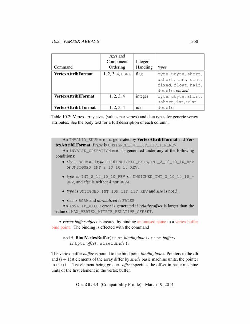
10.3. VERTEX ARRAYS 358
sizes andComponent Integer
Command Ordering Handling typesVertexAttribFormat 1, 2, 3, 4, BGRA flag byte, ubyte, short,
ushort, int, uint,fixed, float, half,double, packed
VertexAttribIFormat 1, 2, 3, 4 integer byte, ubyte, short,ushort, int, uint
VertexAttribLFormat 1, 2, 3, 4 n/a double
Table 10.2: Vertex array sizes (values per vertex) and data types for generic vertexattributes. See the body text for a full description of each column.
An INVALID_ENUM error is generated by VertexAttribIFormat and Ver-texAttribLFormat if type is UNSIGNED_INT_10F_11F_11F_REV.
An INVALID_OPERATION error is generated under any of the followingconditions:• size is BGRA and type is not UNSIGNED_BYTE, INT_2_10_10_10_REV
or UNSIGNED_INT_2_10_10_10_REV;
• type is INT_2_10_10_10_REV or UNSIGNED_INT_2_10_10_10_-
REV, and size is neither 4 nor BGRA;
• type is UNSIGNED_INT_10F_11F_11F_REV and size is not 3.
• size is BGRA and normalized is FALSE.An INVALID_VALUE error is generated if relativeoffset is larger than the
value of MAX_VERTEX_ATTRIB_RELATIVE_OFFSET.
A vertex buffer object is created by binding an unused name to a vertex bufferbind point. The binding is effected with the command
void BindVertexBuffer( uint bindingindex, uint buffer,intptr offset, sizei stride );
The vertex buffer buffer is bound to the bind point bindingindex. Pointers to the ithand (i+ 1)st elements of the array differ by stride basic machine units, the pointerto the (i + 1)st element being greater. offset specifies the offset in basic machineunits of the first element in the vertex buffer.
OpenGL 4.4 (Compatibility Profile) - March 19, 2014
10.3. VERTEX ARRAYS 359
If buffer has not been previously bound, or has been deleted since the last bind-ing, the GL creates a new state vector, initialized with a zero-sized memory bufferand comprising all the state and with the same initial values listed in table 6.2, justas for BindBuffer.
BindVertexBuffer may also be used to bind an existing buffer object. If thebind is successful no change is made to the state of the newly bound buffer object,and any previous binding to bindingindex is broken.
If buffer is zero, any buffer object bound to bindingindex is detached.
Errors
An INVALID_VALUE error is generated if bindingindex is greater than orequal to the value of MAX_VERTEX_ATTRIB_BINDINGS.
An INVALID_VALUE error is generated if stride or offset is negative, or ifstride is greater than the value of MAX_VERTEX_ATTRIB_STRIDE.
The command
void BindVertexBuffers( uint first, sizei count, constuint *buffers, const intptr *offsets, constsizei *strides );
binds count existing buffer objects to vertex buffer binding points numbered firstthrough first + count − 1. If buffers is not NULL, it specifies an array of countvalues, each of which must be zero or the name of an existing buffer object. offsetsand strides specify arrays of count values indicating the offset of the first elementand stride between elements in each buffer, respectively. If buffers is NULL, eachaffected vertex buffer binding point from first through first + count − 1 will bereset to have no bound buffer object. In this case, the offsets and strides associatedwith the binding points are set to default values, ignoring offsets and strides.
BindVertexBuffers is equivalent to
for (i = 0; i < count; i++) {if (buffers == NULL) {
BindVertexBuffer(first + i, 0, 0, 16);} else {
BindVertexBuffer(first + i, buffers[i], offsets[i],strides[i]);
}}
OpenGL 4.4 (Compatibility Profile) - March 19, 2014
10.3. VERTEX ARRAYS 360
except that buffers will not be created if they do not exist.The values specified in buffers, offsets, and strides will be checked separately
for each vertex buffer binding point. When a value for a specific vertex bufferbinding point is invalid, the state for that binding point will be unchanged and anerror will be generated. However, state for other vertex buffer binding points willstill be changed if their corresponding values are valid.
Errors
An INVALID_OPERATION error is generated if first + count is greaterthan the value of MAX_VERTEX_ATTRIB_BINDINGS.
An INVALID_OPERATION error is generated if any value in buffers is notzero or the name of an existing buffer object (per binding).
An INVALID_VALUE error is generated if any value in offsets or stridesis negative, or if stride is greater than the value of MAX_VERTEX_ATTRIB_-STRIDE (per binding).
The association between a vertex attribute and the vertex buffer binding usedby that attribute is set by the command
void VertexAttribBinding( uint attribindex,uint bindingindex );
Errors
An INVALID_VALUE error is generated if attribindex is greater than orequal to the value of MAX_VERTEX_ATTRIBS.
An INVALID_VALUE error is generated if bindingindex is greater than orequal to the value of MAX_VERTEX_ATTRIB_BINDINGS.
The one, two, three, or four values in an array that correspond to a single vertexcomprise an array element. When size is BGRA, it indicates four values. The valueswithin each array element are stored sequentially in memory. However, if size isBGRA, the first, second, third, and fourth values of each array element are takenfrom the third, second, first, and fourth values in memory respectively.
The commands
void VertexAttribPointer( uint index, int size, enum type,boolean normalized, sizei stride, constvoid *pointer );
OpenGL 4.4 (Compatibility Profile) - March 19, 2014
10.3. VERTEX ARRAYS 361
void VertexAttribIPointer( uint index, int size, enum type,sizei stride, const void *pointer );
void VertexAttribLPointer( uint index, int size, enum type,sizei stride, const void *pointer );
control vertex attribute state, a vertex buffer binding, and the mapping between avertex attribute and a vertex buffer binding. They are equivalent to (assuming noerrors are generated):
VertexAttrib*Format(index, size, type, {normalized, }, 0);VertexAttribBinding(index, index);if (stride != 0) {
effectiveStride = stride;} else {
compute effectiveStride based on size and type;}VERTEX_ATTRIB_ARRAY_STRIDE[index] = stride;// This sets VERTEX_BINDING_STRIDE to effectiveStrideVERTEX_ATTRIB_ARRAY_POINTER[index] = pointer;BindVertexBuffer(index, buffer bound to ARRAY_BUFFER,
(char *)pointer - (char *)NULL, effectiveStride);
If stride is specified as zero, then array elements are stored sequentially.
Errors
An INVALID_VALUE error is generated if stride is greater than the valueof MAX_VERTEX_ATTRIB_STRIDE.
An INVALID_OPERATION error is generated if a non-zero vertex arrayobject is bound, no buffer is bound to ARRAY_BUFFER, and pointer is notNULL.
In addition, any of the errors defined by VertexAttrib*Format and Ver-texAttribBinding may be generated if the parameters passed to those com-mands in the equivalent code above would generate those errors.
An individual generic vertex attribute array is enabled or disabled by callingone of
void EnableVertexAttribArray( uint index );void DisableVertexAttribArray( uint index );
OpenGL 4.4 (Compatibility Profile) - March 19, 2014
10.3. VERTEX ARRAYS 362
where index identifies the generic vertex attribute array to enable or disable.
Errors
An INVALID_VALUE error is generated if index is greater than or equal tothe value of MAX_VERTEX_ATTRIBS.
10.3.2 Specifying Arrays for Fixed-Function Attributes
The commands
void VertexPointer( int size, enum type, sizei stride,const void *pointer );
void NormalPointer( enum type, sizei stride, constvoid *pointer );
void ColorPointer( int size, enum type, sizei stride,const void *pointer );
void SecondaryColorPointer( int size, enum type,sizei stride, const void *pointer );
void IndexPointer( enum type, sizei stride, constvoid *pointer );
void EdgeFlagPointer( sizei stride, const void *pointer );void FogCoordPointer( enum type, sizei stride, const
void *pointer );void TexCoordPointer( int size, enum type, sizei stride,
const void *pointer );
specify the location and organization of arrays to store vertex coordinates, normals,colors, secondary colors, color indices, edge flags, fog coordinates, and the valueof MAX_TEXTURE_COORDS multiple texture coordinate sets, respectively.
size, type, stride, and pointer have the same meaning as in VertexAt-trib*Pointer , and table 10.3 indicates the allowable values of size and type forthese commands in the same fashion as table 10.2. type UNSIGNED_INT_10F_-11F_11F_REV is not permitted for any of these commands.
Because edge flags are always type boolean, EdgeFlagPointer has no typeargument.
Because normals are always specified with three values, NormalPointer hasno size argument. Likewise, because color indices and edge flags are always spec-ified with a single value, IndexPointer and EdgeFlagPointer also have no sizeargument.
OpenGL 4.4 (Compatibility Profile) - March 19, 2014
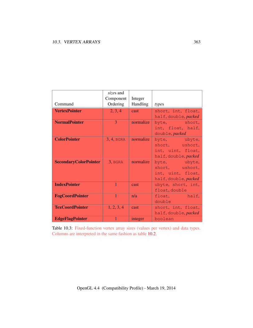
10.3. VERTEX ARRAYS 363
sizes andComponent Integer
Command Ordering Handling typesVertexPointer 2, 3, 4 cast short, int, float,
half, double, packedNormalPointer 3 normalize byte, short,
int, float, half,double, packed
ColorPointer 3, 4, BGRA normalize byte, ubyte,short, ushort,int, uint, float,half, double, packed
SecondaryColorPointer 3, BGRA normalize byte, ubyte,short, ushort,int, uint, float,half, double, packed
IndexPointer 1 cast ubyte, short, int,float, double
FogCoordPointer 1 n/a float, half,double
TexCoordPointer 1, 2, 3, 4 cast short, int, float,half, double, packed
EdgeFlagPointer 1 integer boolean
Table 10.3: Fixed-function vertex array sizes (values per vertex) and data types.Columns are interpreted in the same fashion as table 10.2.
OpenGL 4.4 (Compatibility Profile) - March 19, 2014
10.3. VERTEX ARRAYS 364
Errors
Errors for these commands are the same as for VertexAttrib*Pointer,although not all error conditions described apply since these commands donot take all of the same parameters as VertexAttrib*Pointer.
An INVALID_ENUM error is generated if type is UNSIGNED_INT_10F_-11F_11F_REV.
An individual array is enabled or disabled by calling one of
void EnableClientState( enum array );void DisableClientState( enum array );
with array set to VERTEX_ARRAY, NORMAL_ARRAY, COLOR_ARRAY,SECONDARY_COLOR_ARRAY, INDEX_ARRAY, EDGE_FLAG_ARRAY, FOG_-
COORD_ARRAY, or TEXTURE_COORD_ARRAY, for the vertex, normal, color,secondary color, color index, edge flag, fog coordinate, or texture coordinate array,respectively.
Errors
An INVALID_VALUE error is generated if array is not one of the valueslisted above describing a fixed-function attribute array.
The command
void ClientActiveTexture( enum texture );
is used to select the vertex array client state parameters to be modified by the Tex-CoordPointer command and the array affected by EnableClientState and Dis-ableClientState with parameter TEXTURE_COORD_ARRAY. This command sets theclient state variable CLIENT_ACTIVE_TEXTURE. Each texture coordinate set hasa client state vector which is selected when this command is invoked. This statevector includes the vertex array state. This call also selects the texture coordinateset state used for queries of client state.
Errors
An INVALID_ENUM error is generated if texture is not one of the tokensTEXTUREi, where i is in the range zero to the value of MAX_TEXTURE_COORDS
OpenGL 4.4 (Compatibility Profile) - March 19, 2014
10.3. VERTEX ARRAYS 365
(the implementation-dependent number of texture coordinate sets) minus one.
10.3.3 Vertex Attribute Divisors
Each generic vertex attribute has a corresponding divisor which modifies the rateat which attributes advance, which is useful when rendering multiple instances ofprimitives in a single draw call. If the divisor is zero, the corresponding attributesadvance once per vertex. Otherwise, attributes advance once per divisor instancesof the set(s) of vertices being rendered. A generic attribute is referred to as in-stanced if its corresponding divisor value is non-zero.
The command
void VertexBindingDivisor( uint bindingindex,uint divisor );
sets the divisor value for attributes taken from the buffer bound to bindingindex.
Errors
An INVALID_VALUE error is generated if bindingindex is greater than orequal to the value of MAX_VERTEX_ATTRIB_BINDINGS.
The command
void VertexAttribDivisor( uint index, uint divisor );
is equivalent to (assuming no errors are generated):
VertexAttribBinding(index, index);VertexBindingDivisor(index, divisor);
Errors
An INVALID_VALUE error is generated if index is greater than or equal tothe value of MAX_VERTEX_ATTRIBS.
10.3.4 Transferring Array Elements
When an vertex is transferred to the GL by DrawArrays, DrawElements, or theother Draw* commands described below, each generic attribute is expanded to fourcomponents. If size is one then the x component of the attribute is specified by the
OpenGL 4.4 (Compatibility Profile) - March 19, 2014
10.3. VERTEX ARRAYS 366
array; the y, z, and w components are implicitly set to 0, 0, and 1, respectively. Ifsize is two then the x and y components of the attribute are specified by the array;the z and w components are implicitly set to 0 and 1, respectively. If size is threethen x, y, and z are specified, and w is implicitly set to 1. If size is four then allcomponents are specified.
10.3.5 Primitive Restart
Primitive restarting is enabled or disabled by calling one of the commands
void Enable( enum target );
and
void Disable( enum target );
with target PRIMITIVE_RESTART. The command
void PrimitiveRestartIndex( uint index );
specifies the index of a vertex array element that is treated specially when primitiverestarting is enabled. This value is called the primitive restart index.
When one of the Draw* commands transfers a set of generic attribute arrayelements to the GL, if the index within the vertex arrays corresponding to that setis equal to the primitive restart index, then the GL does not process those elementsas a vertex. Instead, it is as if the drawing command ended with the immediatelypreceding transfer, and another drawing command is immediately started with thesame parameters, but only transferring the immediately following element throughthe end of the originally specified elements.
When one of the *BaseVertex drawing commands specified in section 10.5 isused, the primitive restart comparison occurs before the basevertex offset is addedto the array index.
Primitive restart also affects drawing between Begin and End as described insection 10.8.4.
Primitive restart can also be enabled or disabled with a target of PRIMITIVE_-RESTART_FIXED_INDEX. In this case, the primitive restart index is equal to2N − 1, where N is 8, 16 or 32 if the type is UNSIGNED_BYTE, UNSIGNED_-SHORT, or UNSIGNED_INT, respectively, and the index value specified by Primi-tiveRestartIndex is ignored.
If both PRIMITIVE_RESTART and PRIMITIVE_RESTART_FIXED_INDEX areenabled, the index value determined by PRIMITIVE_RESTART_FIXED_INDEX is
OpenGL 4.4 (Compatibility Profile) - March 19, 2014
10.3. VERTEX ARRAYS 367
used. If PRIMITIVE_RESTART_FIXED_INDEX is enabled, primitive restart is notperformed for array elements transferred by any drawing command not taking atype parameter, including ArrayElement and all of the *Draw* commands otherthan *DrawElements*.
Implementations are not required to support primitive restart for separate patchprimitives (primitive type PATCHES). Support can be queried by calling Get-Booleanv with the symbolic constant PRIMITIVE_RESTART_FOR_PATCHES_-SUPPORTED. A value of FALSE indicates that primitive restart is treated as dis-abled when drawing patches, no matter the value of the enables. A value of TRUEindicates that primitive restart behaves normally for patches.
10.3.6 Robust Buffer Access
Robust buffer access can be enabled by creating a context with robust access en-abled through the window system binding APIs. When enabled, indices within theelement array (see section 10.3.9) that reference vertex data that lies outside theenabled attribute’s vertex buffer object result in reading zero. It is not possible toread vertex data from outside the enabled vertex buffer objects or from another GLcontext, and these accesses do not result in abnormal program termination.
10.3.7 Packed Vertex Data Formats
Vertex data formats UNSIGNED_INT_2_10_10_10_REV and INT_2_10_10_-
10_REV describe packed, 4 component formats stored in a single 32-bit word.For UNSIGNED_INT_2_10_10_10_REV, the first (x), second (y), and third (z)
components are represented as 10-bit unsigned integer values and the fourth (w)component is represented as a 2-bit unsigned integer value.
For INT_2_10_10_10_REV, the x, y and z components are represented as 10-bit signed two’s complement integer values and the w component is represented asa 2-bit signed two’s complement integer value.
The normalized value is used to indicate whether to normalize the data to [0, 1](for unsigned types) or [−1, 1] (for signed types). During normalization, the con-version rules specified in equations 2.1 and 2.2 are followed.
Tables 10.4 and 10.5 describe how these components are laid out in a 32-bitword.
Vertex data format UNSIGNED_INT_10F_11F_11F_REV describes a packed,3-component format that is stored in a single 32-bit word. The first (x), and sec-ond (y) components are represented as 11-bit unsigned floating-point values, andthe third (z) component is represented as a 10-bit unsigned floating-point value.Table 10.6 describes how these components are laid out in a 32-bit word.
OpenGL 4.4 (Compatibility Profile) - March 19, 2014
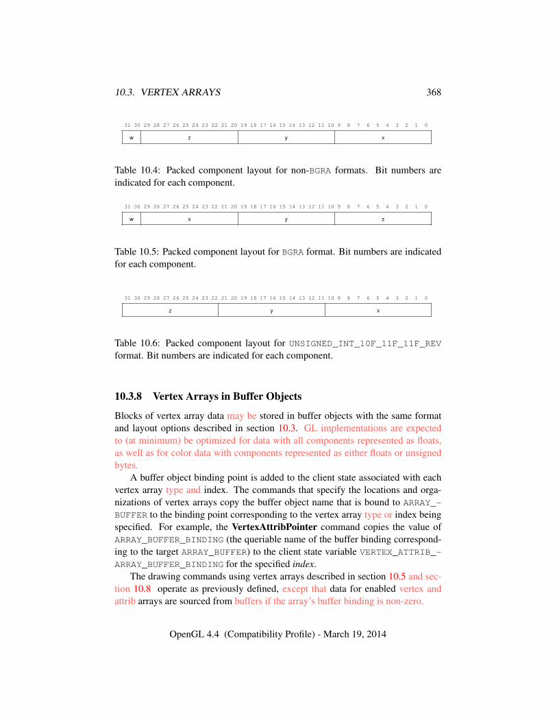
10.3. VERTEX ARRAYS 368
31 30 29 28 27 26 25 24 23 22 21 20 19 18 17 16 15 14 13 12 11 10 9 8 7 6 5 4 3 2 1 0
w z y x
Table 10.4: Packed component layout for non-BGRA formats. Bit numbers areindicated for each component.
31 30 29 28 27 26 25 24 23 22 21 20 19 18 17 16 15 14 13 12 11 10 9 8 7 6 5 4 3 2 1 0
w x y z
Table 10.5: Packed component layout for BGRA format. Bit numbers are indicatedfor each component.
31 30 29 28 27 26 25 24 23 22 21 20 19 18 17 16 15 14 13 12 11 10 9 8 7 6 5 4 3 2 1 0
z y x
Table 10.6: Packed component layout for UNSIGNED_INT_10F_11F_11F_REVformat. Bit numbers are indicated for each component.
10.3.8 Vertex Arrays in Buffer Objects
Blocks of vertex array data may be stored in buffer objects with the same formatand layout options described in section 10.3. GL implementations are expectedto (at minimum) be optimized for data with all components represented as floats,as well as for color data with components represented as either floats or unsignedbytes.
A buffer object binding point is added to the client state associated with eachvertex array type and index. The commands that specify the locations and orga-nizations of vertex arrays copy the buffer object name that is bound to ARRAY_-
BUFFER to the binding point corresponding to the vertex array type or index beingspecified. For example, the VertexAttribPointer command copies the value ofARRAY_BUFFER_BINDING (the queriable name of the buffer binding correspond-ing to the target ARRAY_BUFFER) to the client state variable VERTEX_ATTRIB_-ARRAY_BUFFER_BINDING for the specified index.
The drawing commands using vertex arrays described in section 10.5 and sec-tion 10.8 operate as previously defined, except that data for enabled vertex andattrib arrays are sourced from buffers if the array’s buffer binding is non-zero.
OpenGL 4.4 (Compatibility Profile) - March 19, 2014
10.3. VERTEX ARRAYS 369
When an array is sourced from a buffer object for a vertex attribute, thebindingindex set with VertexAttribBinding for that attribute indicates which ver-tex buffer binding is used. The sum of the relativeoffset set for the attributewith VertexAttrib*Format and the offset set for the vertex buffer with BindVer-texBuffer is used as the offset in basic machine units of the first element in thatbuffer’s data store.
When a generic attribute array is sourced from client memory, the vertex at-tribute binding state is ignored. Instead, the pointer, size, type, and stride parame-ters set with VertexAttrib*Pointer for that attribute indicate the location in clientmemory of attribute values and their size, type, and stride, respectively.
It is acceptable for vertex or attribute arrays to be sourced from any combina-tion of client memory and various buffer objects during a single rendering opera-tion.
10.3.9 Array Indices in Buffer Objects
Blocks of array indices may be stored in buffer objects with the same formatoptions that are supported for client-side index arrays. Initially zero is boundto ELEMENT_ARRAY_BUFFER, indicating that DrawElements, DrawRangeEle-ments, and DrawElementsInstanced are to source their indices from arrayspassed as their indices parameters, and that MultiDrawElements is to source itsindices from the array of pointers to arrays passed in as its indices parameter.
A buffer object is bound to ELEMENT_ARRAY_BUFFER by calling BindBufferwith target set to ELEMENT_ARRAY_BUFFER, and buffer set to the name of thebuffer object. If no corresponding buffer object exists, one is initialized as definedin section 6.
While a non-zero buffer object name is bound to ELEMENT_ARRAY_BUFFER,DrawElements, DrawRangeElements, and DrawElementsInstanced source
their indices from that buffer object, using their indices parameters as off-sets into the buffer object in the same fashion as described in section 10.3.8.DrawElementsBaseVertex, DrawRangeElementsBaseVertex, and DrawEle-mentsInstancedBaseVertex also source their indices from that buffer object,adding the basevertex offset to the appropriate vertex index as a final step before in-dexing into the vertex buffer; this does not affect the calculation of the base pointerfor the index array. Finally, MultiDrawElements and MultiDrawElementsBa-seVertex also source their indices from that buffer object, using its indices param-eter as a pointer to an array of pointers that represent offsets into the buffer object.
In some cases performance will be optimized by storing indices and array datain separate buffer objects, and by creating those buffer objects with the correspond-ing binding points.
OpenGL 4.4 (Compatibility Profile) - March 19, 2014
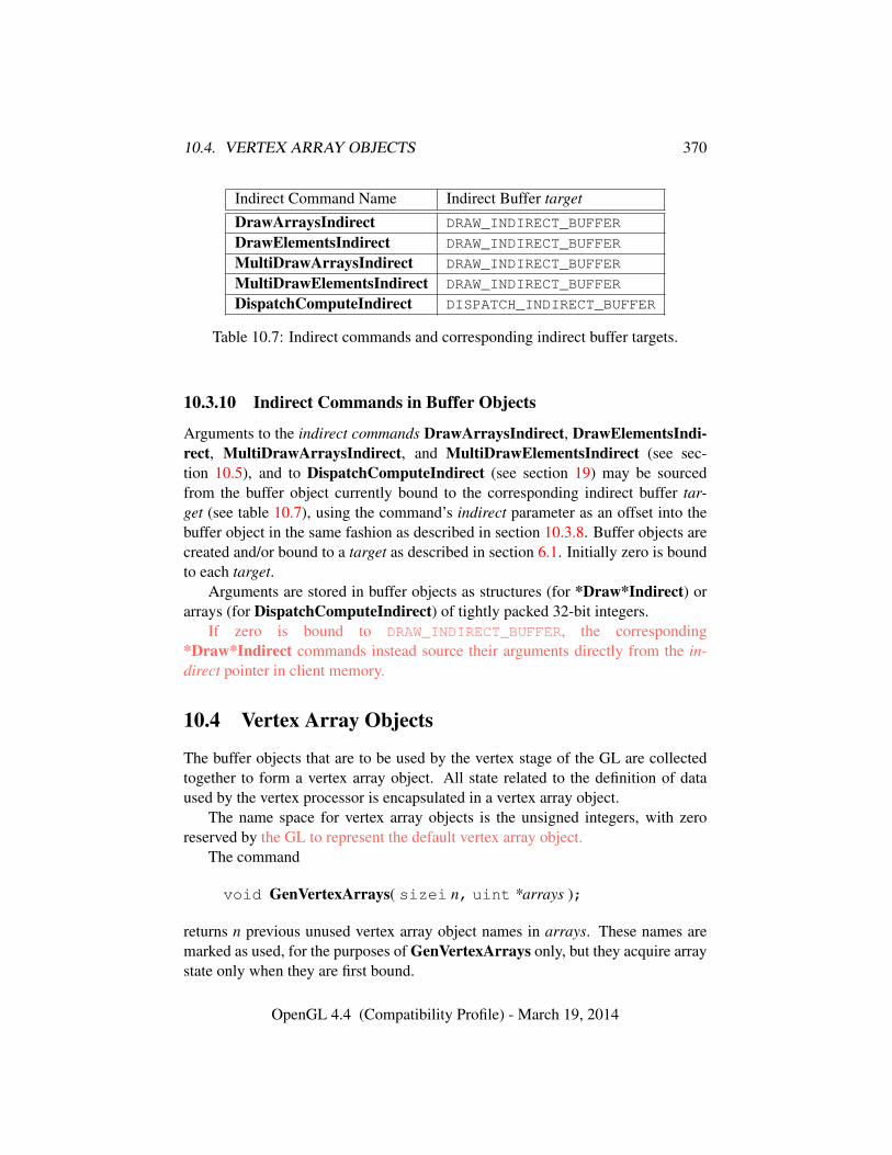
10.4. VERTEX ARRAY OBJECTS 370
Indirect Command Name Indirect Buffer target
DrawArraysIndirect DRAW_INDIRECT_BUFFER
DrawElementsIndirect DRAW_INDIRECT_BUFFER
MultiDrawArraysIndirect DRAW_INDIRECT_BUFFER
MultiDrawElementsIndirect DRAW_INDIRECT_BUFFER
DispatchComputeIndirect DISPATCH_INDIRECT_BUFFER
Table 10.7: Indirect commands and corresponding indirect buffer targets.
10.3.10 Indirect Commands in Buffer Objects
Arguments to the indirect commands DrawArraysIndirect, DrawElementsIndi-rect, MultiDrawArraysIndirect, and MultiDrawElementsIndirect (see sec-tion 10.5), and to DispatchComputeIndirect (see section 19) may be sourcedfrom the buffer object currently bound to the corresponding indirect buffer tar-get (see table 10.7), using the command’s indirect parameter as an offset into thebuffer object in the same fashion as described in section 10.3.8. Buffer objects arecreated and/or bound to a target as described in section 6.1. Initially zero is boundto each target.
Arguments are stored in buffer objects as structures (for *Draw*Indirect) orarrays (for DispatchComputeIndirect) of tightly packed 32-bit integers.
If zero is bound to DRAW_INDIRECT_BUFFER, the corresponding*Draw*Indirect commands instead source their arguments directly from the in-direct pointer in client memory.
10.4 Vertex Array Objects
The buffer objects that are to be used by the vertex stage of the GL are collectedtogether to form a vertex array object. All state related to the definition of dataused by the vertex processor is encapsulated in a vertex array object.
The name space for vertex array objects is the unsigned integers, with zeroreserved by the GL to represent the default vertex array object.
The command
void GenVertexArrays( sizei n, uint *arrays );
returns n previous unused vertex array object names in arrays. These names aremarked as used, for the purposes of GenVertexArrays only, but they acquire arraystate only when they are first bound.
OpenGL 4.4 (Compatibility Profile) - March 19, 2014
10.4. VERTEX ARRAY OBJECTS 371
Errors
An INVALID_VALUE error is generated if n is negative.
Vertex array objects are deleted by calling
void DeleteVertexArrays( sizei n, const uint *arrays );
arrays contains n names of vertex array objects to be deleted. Once a vertex arrayobject is deleted it has no contents and its name is again unused. If a vertex arrayobject that is currently bound is deleted, the binding for that object reverts to zeroand the default vertex array becomes current. Unused names in arrays that havebeen marked as used for the purposes of GenVertexArrays are marked as unusedagain. Unused names in arrays are silently ignored, as is the value zero.
Errors
An INVALID_VALUE error is generated if n is negative.
A vertex array object is created by binding a name returned by GenVertexAr-rays with the command
void BindVertexArray( uint array );
array is the vertex array object name. The resulting vertex array object is a newstate vector, comprising all the state and with the same initial values listed in ta-bles 23.4- 23.7.
BindVertexArray may also be used to bind an existing vertex array object.If the bind is successful no change is made to the state of the bound vertex arrayobject, and any previous binding is broken.
The currently bound vertex array object is used for all commands which modifyvertex array state, such as VertexAttribPointer and EnableVertexAttribArray;all commands which draw from vertex arrays, such as DrawArrays and DrawEle-ments; and all queries of vertex array state (see chapter 22).
Errors
An INVALID_OPERATION error is generated if array is not zero or a namereturned from a previous call to GenVertexArrays, or if such a name has sincebeen deleted with DeleteVertexArrays.
OpenGL 4.4 (Compatibility Profile) - March 19, 2014
10.5. DRAWING COMMANDS USING VERTEX ARRAYS 372
The command
boolean IsVertexArray( uint array );
returns TRUE if array is the name of a vertex array object. If array is zero, or anon-zero value that is not the name of a vertex array object, IsVertexArray returnsFALSE. No error is generated if array is not a valid vertex array object name.
10.5 Drawing Commands Using Vertex Arrays
The command
void DrawArraysOneInstance( enum mode, int first,sizei count, int instance, uint baseinstance );
does not exist in the GL, but is used to describe functionality in the rest of this sec-tion. This command constructs a sequence of geometric primitives by successivelytransferring elements for count vertices. Elements first through first + count − 1of each enabled non-instanced array are transferred to the GL. mode specifies whatkind of primitives are constructed, and must be one of the primitive types definedin section 10.1.
If an enabled vertex attribute array is instanced (it has a non-zero divisor asspecified by VertexAttribDivisor), the element index that is transferred to the GL,for all vertices, is given by⌊
instance
divisor
⌋+ baseinstance
If an array corresponding to an attribute required by a vertex shader is notenabled, then the corresponding element is taken from the current attribute state(see section 10.2).
If an array is enabled, the corresponding current vertex attribute value is unaf-fected by the execution of DrawArraysOneInstance.
The value of instance may be read by a vertex shader as gl_InstanceID, asdescribed in section 11.1.3.9.
Errors
An INVALID_ENUM error is generated if mode is not one of the primitivetypes defined in section 10.1.
Specifying first < 0 results in undefined behavior. Generating anINVALID_VALUE error is recommended in this case.
OpenGL 4.4 (Compatibility Profile) - March 19, 2014
10.5. DRAWING COMMANDS USING VERTEX ARRAYS 373
An INVALID_VALUE error is generated if count is negative.
The command
void DrawArrays( enum mode, int first, sizei count );
is equivalent to
DrawArraysOneInstance(mode, first, count, 0, 0);
The command
void DrawArraysInstancedBaseInstance( enum mode,int first, sizei count, sizei instancecount,uint baseinstance );
behaves identically to DrawArrays except that instancecount instances of therange of elements are executed and the value of instance advances for each it-eration. Those attributes that have non-zero values for divisor, as specified byVertexAttribDivisor, advance once every divisor instances. Additionally, the firstelement within those instanced vertex attributes is specified in baseinstance.
DrawArraysInstancedBaseInstance is equivalent to
if (mode, count, or instancecount is invalid)generate appropriate error
else {for (i = 0; i < instancecount; i++) {
DrawArraysOneInstance(mode, first, count, i,baseinstance);
}}
The command
void DrawArraysInstanced( enum mode, int first,sizei count, sizei instancecount );
is equivalent to
DrawArraysInstancedBaseInstance(mode, first, count, instancecount, 0);
The command
OpenGL 4.4 (Compatibility Profile) - March 19, 2014
10.5. DRAWING COMMANDS USING VERTEX ARRAYS 374
void DrawArraysIndirect( enum mode, constvoid *indirect );
is equivalent to
typedef struct {uint count;uint instanceCount;uint first;uint baseInstance;
} DrawArraysIndirectCommand;
DrawArraysIndirectCommand *cmd =(DrawArraysIndirectCommand *)indirect;
DrawArraysInstancedBaseInstance(mode, cmd->first, cmd->count,cmd->instanceCount, cmd->baseInstance);
As with DrawArraysInstanced, vertex attributes may be sourced from clientarrays or vertex buffer objects. Unlike DrawArraysInstanced, first is unsignedand cannot cause an error.
Errors
An INVALID_OPERATION error is generated if the command wouldsource data beyond the end of the buffer object.
An INVALID_VALUE error is generated if indirect is not a multiple of thesize, in basic machine units, of uint.
All elements of DrawArraysIndirectCommand are tightly packed 32 bit val-ues.
The command
void MultiDrawArrays( enum mode, const int *first,const sizei *count, sizei drawcount );
behaves identically to DrawArraysInstanced except that drawcount separateranges of elements are specified instead, all elements are treated as though theyare not instanced, and the value of instance remains zero. It is equivalent to
if (mode or drawcount is invalid)generate appropriate error
OpenGL 4.4 (Compatibility Profile) - March 19, 2014
10.5. DRAWING COMMANDS USING VERTEX ARRAYS 375
else {for (i = 0; i < drawcount; i++) {
if (count[i] > 0)DrawArraysOneInstance(mode, first[i], count[i],
0, 0);}
}
The command
void MultiDrawArraysIndirect( enum mode, constvoid *indirect, sizei drawcount, sizei stride );
behaves identically to DrawArraysIndirect except that indirect is treated as anarray of drawcount DrawArraysIndirectCommand structures. indirect containsthe offset of the first element of the array within the buffer currently bound to theDRAW_INDIRECT buffer binding. stride specifies the distance, in basic machineunits, between the elements of the array. If stride is zero, the array elements aretreated as tightly packed.
It is equivalent to
if (mode is invalid)generate appropriate error
else {const ubyte *ptr = (const ubyte *)indirect;for (i = 0; i < drawcount; i++) {
DrawArraysIndirect(mode, (DrawArraysIndirectCommand*)ptr);if (stride == 0) {
ptr += sizeof(DrawArraysIndirectCommand);} else {
ptr += stride;}
}}
Errors
An INVALID_VALUE error is generated if stride is neither zero nor a mul-tiple of four.
An INVALID_VALUE error is generated if drawcount is not positive.
OpenGL 4.4 (Compatibility Profile) - March 19, 2014
10.5. DRAWING COMMANDS USING VERTEX ARRAYS 376
The command
void DrawElementsOneInstance( enum mode, sizei count,enum type, const void *indices, int instance,uint baseinstance );
does not exist in the GL, but is used to describe functionality in the rest of this sec-tion. This command constructs a sequence of geometric primitives by successivelytransferring elements for count vertices to the GL. The ith element transferred byDrawElementsOneInstance will be taken from element indices[i] (if no elementarray buffer is bound), or from the element whose index is stored in the currentlybound element array buffer at offset indices + i .
type must be one of UNSIGNED_BYTE, UNSIGNED_SHORT, or UNSIGNED_-INT, indicating that the index values are of GL type ubyte, ushort, or uintrespectively. mode specifies what kind of primitives are constructed, and must beone of the primitive types defined in section 10.1.
If an enabled vertex attribute array is instanced (it has a non-zero divisor asspecified by VertexAttribDivisor), the element index that is transferred to the GL,for all vertices, is given by⌊
instance
divisor
⌋+ baseinstance
If an array corresponding to an attribute required by a vertex shader is notenabled, then the corresponding element is taken from the current attribute state(see section 10.2).
GL implementations do not restrict index values; any value representable in auintmay be used. However, for compatibility with OpenGL ES implementations,the maximum representable index vaue may be queried by calling GetInteger64vwith pname MAX_ELEMENT_INDEX, and will return 232 − 1.
If an array is enabled, the corresponding current vertex attribute value is unaf-fected by the execution of DrawElementsOneInstance.
The value of instance may be read by a vertex shader as gl_InstanceID, asdescribed in section 11.1.3.9.
Errors
An INVALID_ENUM error is generated if mode is not one of the primitivetypes defined in section 10.1.
An INVALID_ENUM error is generated if type is not UNSIGNED_BYTE,
OpenGL 4.4 (Compatibility Profile) - March 19, 2014
10.5. DRAWING COMMANDS USING VERTEX ARRAYS 377
UNSIGNED_SHORT, or UNSIGNED_INT.
The command
void DrawElements( enum mode, sizei count, enum type,const void *indices );
behaves identically to DrawElementsOneInstance with the instance and basein-stance parameters set to zero; the effect of calling
DrawElements(mode, count, type, indices);
is equivalent
if (mode, count or type is invalid)generate appropriate error
elseDrawElementsOneInstance(mode, count, type, indices, 0, 0);
The command
void DrawElementsInstancedBaseInstance( enum mode,sizei count, enum type, const void *indices,sizei instancecount, uint baseinstance );
behaves identically to DrawElements except that instancecount instances of theset of elements are executed and the value of instance advances between each set.Instanced attributes are advanced as they do during execution of DrawArraysIn-stancedBaseInstance, and baseinstance has the same effect. It is equivalent to
if (mode, count, type, or instancecount is invalid)generate appropriate error
else {for (int i = 0; i < instancecount; i++) {
DrawElementsOneInstance(mode, count, type, indices, i,baseinstance);
}}
The command
void DrawElementsInstanced( enum mode, sizei count,enum type, const void *indices, sizei instancecount );
OpenGL 4.4 (Compatibility Profile) - March 19, 2014
10.5. DRAWING COMMANDS USING VERTEX ARRAYS 378
behaves identically to DrawElementsInstancedBaseInstance except that basein-stance is zero. It is equivalent to
DrawElementsInstancedBaseInstance(mode, count, type, indices,instancecount, 0);
The command
void MultiDrawElements( enum mode, constsizei *count, enum type, const void * const *indices,sizei drawcount );
behaves identically to DrawElementsInstanced except that drawcount separatesets of elements are specified instead, all elements are treated as though they arenot instanced, and the value of instance remains zero. It is equivalent to
if (mode, count, drawcount, or type is invalid)generate appropriate error
else {for (int i = 0; i < drawcount; i++)
DrawElementsOneInstance(mode, count[i], type,indices[i], 0, 0);
}
The command
void DrawRangeElements( enum mode, uint start,uint end, sizei count, enum type, constvoid *indices );
is a restricted form of DrawElements. mode, count, type, and indices match thecorresponding arguments to DrawElements, with the additional constraint that allindex values identified by indices must lie between start and end inclusive.
Implementations denote recommended maximum amounts of vertex and indexdata, which may be queried by calling GetIntegerv with the symbolic constantsMAX_ELEMENTS_VERTICES and MAX_ELEMENTS_INDICES. If end − start + 1is greater than the value of MAX_ELEMENTS_VERTICES, or if count is greater thanthe value of MAX_ELEMENTS_INDICES, then the call may operate at reduced per-formance. There is no requirement that all vertices in the range [start, end] bereferenced. However, the implementation may partially process unused vertices,reducing performance from what could be achieved with an optimal index set.
OpenGL 4.4 (Compatibility Profile) - March 19, 2014
10.5. DRAWING COMMANDS USING VERTEX ARRAYS 379
Errors
An INVALID_VALUE error is generated if end < start.Invalid mode, count, or type parameters generate the same errors as would
the corresponding call to DrawElements.It is an error for index values (other than the primitive restart index,
when primitive restart is enabled) to lie outside the range [start, end], butimplementations are not required to check for this. Such indices will causeimplementation-dependent behavior.
The commands
void DrawElementsBaseVertex( enum mode, sizei count,enum type, const void *indices, int basevertex );
void DrawRangeElementsBaseVertex( enum mode,uint start, uint end, sizei count, enum type, constvoid *indices, int basevertex );
void DrawElementsInstancedBaseVertex( enum mode,sizei count, enum type, const void *indices,sizei instancecount, int basevertex );
void DrawElementsInstancedBaseVertexBaseInstance(enum mode, sizei count, enum type, constvoid *indices, sizei instancecount, int basevertex,uint baseinstance );
are equivalent to the commands with the same base name (without the BaseVertexsuffix), except that the ith element transferred by the corresponding draw call willbe taken from element indices[i] + basevertex of each enabled array. If the result-ing value is larger than the maximum value representable by type, it should behaveas if the calculation were upconverted to 32-bit unsigned integers (with wrappingon overflow conditions). The operation is undefined if the sum would be negativeand should be handled as described in section 6.4. For DrawRangeElementsBa-seVertex, the index values must lie between start and end inclusive, prior to addingthe basevertex offset. Index values lying outside the range [start, end] are treatedin the same way as DrawRangeElements.
For DrawElementsInstancedBaseVertexBaseInstance, baseinstance is usedto offset the element from which instanced vertex attributes (those with a non-zerodivisor as specified by VertexAttribDivisor) are taken.
The command
OpenGL 4.4 (Compatibility Profile) - March 19, 2014
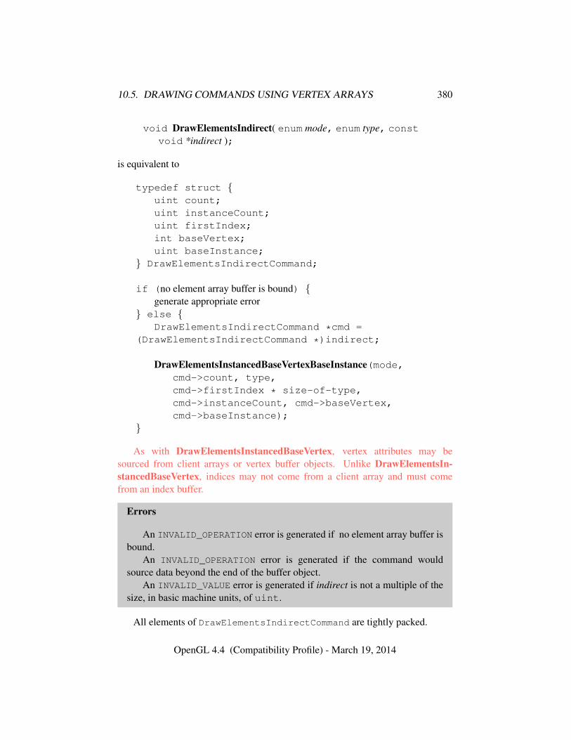
10.5. DRAWING COMMANDS USING VERTEX ARRAYS 380
void DrawElementsIndirect( enum mode, enum type, constvoid *indirect );
is equivalent to
typedef struct {uint count;uint instanceCount;uint firstIndex;int baseVertex;uint baseInstance;
} DrawElementsIndirectCommand;
if (no element array buffer is bound) {generate appropriate error
} else {DrawElementsIndirectCommand *cmd =
(DrawElementsIndirectCommand *)indirect;
DrawElementsInstancedBaseVertexBaseInstance(mode,cmd->count, type,cmd->firstIndex * size-of-type,cmd->instanceCount, cmd->baseVertex,cmd->baseInstance);
}
As with DrawElementsInstancedBaseVertex, vertex attributes may besourced from client arrays or vertex buffer objects. Unlike DrawElementsIn-stancedBaseVertex, indices may not come from a client array and must comefrom an index buffer.
Errors
An INVALID_OPERATION error is generated if no element array buffer isbound.
An INVALID_OPERATION error is generated if the command wouldsource data beyond the end of the buffer object.
An INVALID_VALUE error is generated if indirect is not a multiple of thesize, in basic machine units, of uint.
All elements of DrawElementsIndirectCommand are tightly packed.
OpenGL 4.4 (Compatibility Profile) - March 19, 2014
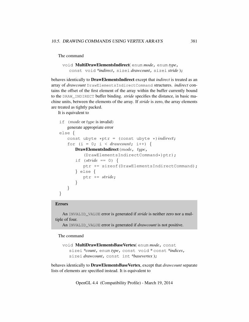
10.5. DRAWING COMMANDS USING VERTEX ARRAYS 381
The command
void MultiDrawElementsIndirect( enum mode, enum type,const void *indirect, sizei drawcount, sizei stride );
behaves identically to DrawElementsIndirect except that indirect is treated as anarray of drawcount DrawElementsIndirectCommand structures. indirect con-tains the offset of the first element of the array within the buffer currently boundto the DRAW_INDIRECT buffer binding. stride specifies the distance, in basic ma-chine units, between the elements of the array. If stride is zero, the array elementsare treated as tightly packed.
It is equivalent to
if (mode or type is invalid)generate appropriate error
else {const ubyte *ptr = (const ubyte *)indirect;for (i = 0; i < drawcount; i++) {
DrawElementsIndirect(mode, type,(DrawElementsIndirectCommand*)ptr);
if (stride == 0) {ptr += sizeof(DrawElementsIndirectCommand);
} else {ptr += stride;
}}
}
Errors
An INVALID_VALUE error is generated if stride is neither zero nor a mul-tiple of four.
An INVALID_VALUE error is generated if drawcount is not positive.
The command
void MultiDrawElementsBaseVertex( enum mode, constsizei *count, enum type, const void * const *indices,sizei drawcount, const int *basevertex );
behaves identically to DrawElementsBaseVertex, except that drawcount separatelists of elements are specified instead. It is equivalent to
OpenGL 4.4 (Compatibility Profile) - March 19, 2014
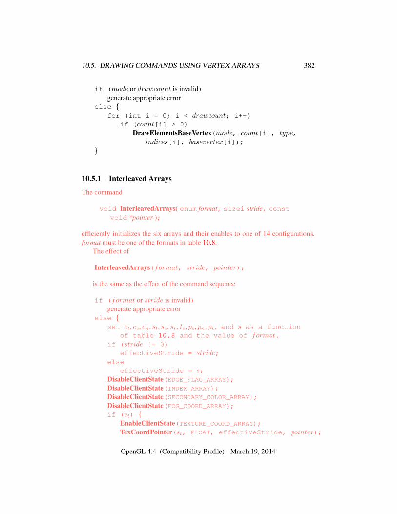
10.5. DRAWING COMMANDS USING VERTEX ARRAYS 382
if (mode or drawcount is invalid)generate appropriate error
else {for (int i = 0; i < drawcount; i++)
if (count[i] > 0)DrawElementsBaseVertex(mode, count[i], type,
indices[i], basevertex[i]);}
10.5.1 Interleaved Arrays
The command
void InterleavedArrays( enum format, sizei stride, constvoid *pointer );
efficiently initializes the six arrays and their enables to one of 14 configurations.format must be one of the formats in table 10.8.
The effect of
InterleavedArrays(format, stride, pointer);
is the same as the effect of the command sequence
if (format or stride is invalid)generate appropriate error
else {set et, ec, en, st, sc, sv, tc, pc, pn, pv, and s as a function
of table 10.8 and the value of format.if (stride != 0)
effectiveStride = stride;else
effectiveStride = s;DisableClientState(EDGE_FLAG_ARRAY);DisableClientState(INDEX_ARRAY);DisableClientState(SECONDARY_COLOR_ARRAY);DisableClientState(FOG_COORD_ARRAY);if (et) {
EnableClientState(TEXTURE_COORD_ARRAY);TexCoordPointer(st, FLOAT, effectiveStride, pointer);
OpenGL 4.4 (Compatibility Profile) - March 19, 2014
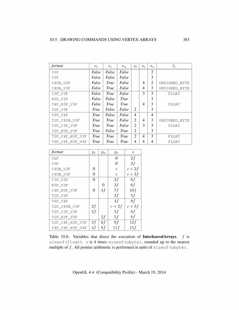
10.5. DRAWING COMMANDS USING VERTEX ARRAYS 383
format et ec en st sc sv tc
V2F False False False 2V3F False False False 3C4UB_V2F False True False 4 2 UNSIGNED_BYTE
C4UB_V3F False True False 4 3 UNSIGNED_BYTE
C3F_V3F False True False 3 3 FLOAT
N3F_V3F False False True 3C4F_N3F_V3F False True True 4 3 FLOAT
T2F_V3F True False False 2 3T4F_V4F True False False 4 4T2F_C4UB_V3F True True False 2 4 3 UNSIGNED_BYTE
T2F_C3F_V3F True True False 2 3 3 FLOAT
T2F_N3F_V3F True False True 2 3T2F_C4F_N3F_V3F True True True 2 4 3 FLOAT
T4F_C4F_N3F_V4F True True True 4 4 4 FLOAT
format pc pn pv s
V2F 0 2fV3F 0 3fC4UB_V2F 0 c c+ 2fC4UB_V3F 0 c c+ 3f
C3F_V3F 0 3f 6fN3F_V3F 0 3f 6fC4F_N3F_V3F 0 4f 7f 10fT2F_V3F 2f 5f
T4F_V4F 4f 8fT2F_C4UB_V3F 2f c+ 2f c+ 5fT2F_C3F_V3F 2f 5f 8fT2F_N3F_V3F 2f 5f 8f
T2F_C4F_N3F_V3F 2f 6f 9f 12fT4F_C4F_N3F_V4F 4f 8f 11f 15f
Table 10.8: Variables that direct the execution of InterleavedArrays. f issizeof(float). c is 4 times sizeof(ubyte), rounded up to the nearestmultiple of f . All pointer arithmetic is performed in units of sizeof(ubyte).
OpenGL 4.4 (Compatibility Profile) - March 19, 2014
10.6. VERTEX ARRAY AND VERTEX ARRAY OBJECT QUERIES 384
} elseDisableClientState(TEXTURE_COORD_ARRAY);
if (ec) {EnableClientState(COLOR_ARRAY);ColorPointer(sc, tc, effectiveStride, pointer + pc);
} elseDisableClientState(COLOR_ARRAY);
if (en) {EnableClientState(NORMAL_ARRAY);NormalPointer(FLOAT, effectiveStride, pointer + pn);
} elseDisableClientState(NORMAL_ARRAY);
EnableClientState(VERTEX_ARRAY);VertexPointer(sv, FLOAT, effectiveStride, pointer + pv);
}
Errors
An INVALID_ENUM error is generated if format is not one of the formatsin table 10.8.
An INVALID_VALUE error is generated if stride is negative.
10.6 Vertex Array and Vertex Array Object Queries
Queries of vertex array state variables are qualified by the value of VERTEX_-ARRAY_BINDING to determine which vertex array object is queried. Tables 23.4-23.7 define the set of state stored in a vertex array object.
The commands
void GetVertexAttribdv( uint index, enum pname,double *params );
void GetVertexAttribfv( uint index, enum pname,float *params );
void GetVertexAttribiv( uint index, enum pname,int *params );
void GetVertexAttribIiv( uint index, enum pname,int *params );
void GetVertexAttribIuiv( uint index, enum pname,uint *params );
OpenGL 4.4 (Compatibility Profile) - March 19, 2014
10.6. VERTEX ARRAY AND VERTEX ARRAY OBJECT QUERIES 385
void GetVertexAttribLdv( uint index, enum pname,double *params );
obtain the vertex attribute state named by pname for the generic vertex attributenumbered index and places the information in the array params. pname mustbe one of VERTEX_ATTRIB_ARRAY_BUFFER_BINDING, VERTEX_ATTRIB_-
ARRAY_ENABLED, VERTEX_ATTRIB_ARRAY_SIZE, VERTEX_ATTRIB_ARRAY_-STRIDE, VERTEX_ATTRIB_ARRAY_TYPE, VERTEX_ATTRIB_ARRAY_-
NORMALIZED, VERTEX_ATTRIB_ARRAY_INTEGER, VERTEX_ATTRIB_ARRAY_-LONG, VERTEX_ATTRIB_ARRAY_DIVISOR, or CURRENT_VERTEX_ATTRIB. NoteVERTEX_ATTRIB_BINDING, VERTEX_ATTRIB_RELATIVE_OFFSET, that all thequeries except CURRENT_VERTEX_ATTRIB return values stored in the currentlybound vertex array object (the value of VERTEX_ARRAY_BINDING). If the zeroobject is bound, these values are client state.
Queries of VERTEX_ATTRIB_ARRAY_BUFFER_BINDING and VERTEX_-
ATTRIB_ARRAY_DIVISOR map the requested attribute index to a binding indexvia the VERTEX_ATTRIB_BINDING state, and then return the value of VERTEX_-BINDING_BUFFER or VERTEX_BINDING_DIVISOR, respectively.
All but CURRENT_VERTEX_ATTRIB return information about generic vertexattribute arrays. The enable state of a generic vertex attribute array is set by thecommand EnableVertexAttribArray and cleared by DisableVertexAttribArray.The size, stride, type, normalized flag, and unconverted integer flag are set by thecommands VertexAttribPointer and VertexAttribIPointer. The normalized flagis always set to FALSE by VertexAttribIPointer. The unconverted integer flag isalways set to FALSE by VertexAttribPointer and TRUE by VertexAttribIPointer.
The query CURRENT_VERTEX_ATTRIB returns the current value for thegeneric attribute index. GetVertexAttribdv and GetVertexAttribfv read and re-turn the current attribute values as four floating-point values; GetVertexAttribivreads them as floating-point values and converts them to four integer values;GetVertexAttribIiv reads and returns them as four signed integers; GetVertex-AttribIuiv reads and returns them as four unsigned integers; and GetVertexAttri-bLdv reads and returns them as four double-precision floating-point values. Theresults of the query are undefined if the current attribute values are read using onedata type but were specified using a different one.
Errors
An INVALID_VALUE error is generated if index is greater than or equal tothe value of MAX_VERTEX_ATTRIBS.
An INVALID_OPERATION error is generated if index is zero and pname
OpenGL 4.4 (Compatibility Profile) - March 19, 2014
10.7. REQUIRED STATE 386
is CURRENT_VERTEX_ATTRIB, since there is no current value for generic at-tribute zero.
An INVALID_OPERATION error is generated if no vertex array object isbound (see section 10.4).
An INVALID_ENUM error is generated if pname is not one of the valueslisted above.
The command
void GetVertexAttribPointerv( uint index, enum pname,const void **pointer );
obtains the pointer named pname for the vertex attribute numbered index and placesthe information in the array pointer. pname must be VERTEX_ATTRIB_ARRAY_-POINTER. The value returned is queried from the currently bound vertex arrayobject. If the zero object is bound, the value is queried from client state.
Errors
An INVALID_VALUE error is generated if index is greater than or equal tothe value of MAX_VERTEX_ATTRIBS.
An INVALID_OPERATION error is generated if no vertex array object isbound (see section 10.4).
10.7 Required State
Let the number of supported generic vertex attributes (the value of MAX_VERTEX_-ATTRIBS) be n. Let the number of supported texture units (the value of MAX_-TEXTURE_COORDS) be m. Let the number of supported generic vertex attributebindings (the value of MAX_VERTEX_ATTRIB_BINDINGS be k.
Then the state required to implement vertex arrays consists of 7+m+n booleanvalues, 7+m+nmemory pointers, 7+m+n integer stride values, symbolic con-stants representing array types, 3+m+n integers representing values per element,n boolean values indicating normalization, n boolean values indicating whetherthe attribute values are pure integers, n integers representing vertex attribute divi-sors, an integer for the client active texture unit selector, n integer vertex attributebinding indices, n integer relative offsets, k 64-bit integer vertex binding offsets, kinteger vertex binding strides, an unsigned integer representing the primitive restartindex, and two booleans representing the enable state of primitive restart and prim-itive restart with a fixed index.
OpenGL 4.4 (Compatibility Profile) - March 19, 2014

10.8. DRAWING COMMANDS USING BEGIN AND END 387
In the initial state, the boolean values are each false, the memory pointers areeach NULL, the strides are each zero, the array types are each FLOAT, the integersrepresenting values per element are each four, the normalized and pure integer flagsare each false, the divisors are each zero, the client active texture unit selector isTEXTURE0, the binding indices are i for each attribute i, the relative offsets areeach zero, the vertex binding offsets are each zero, the vertex binding strides areeach 16, the restart index is zero, and the restart enables are both FALSE.
10.8 Drawing Commands Using Begin and End
In addition to the drawing commands described in section 10.5, vertices defininga sequence of primitives may be transferred to the GL by enclosing commandsdefining attributes of those vertices between the two commands
void Begin( enum mode );void End( void );
mode specifies the primitive type being defined and must be one of the primitivetypes defined in section 10.1. There is no limit on the number of vertices that maybe specified between a Begin and an End.
The state required for Begin and End consists of a sixteen-valued integer indi-cating either one of the possible Begin / End modes, or that no Begin / End modeis being processed.
Errors
An INVALID_ENUM error is generated by Begin if mode is not one of theprimitive types defined in section 10.1.
An INVALID_FRAMEBUFFER_OPERATION error is generated by Begin ifthe framebuffer object bound to DRAW_FRAMEBUFFER_BINDING is not frame-buffer complete (see section 9.4.2).
10.8.1 Transferring Vertices With Vertex Commands
A single vertex is specified between Begin and End by giving its coordinates intwo, three, or four dimensions. This is done using one of several versions of theVertex command:
void Vertex{234}{sifd}( T coords );void Vertex{234}{sifd}v( const T coords );
OpenGL 4.4 (Compatibility Profile) - March 19, 2014
10.8. DRAWING COMMANDS USING BEGIN AND END 388
Vertex coordinates may be stored as packed components within a larger naturaltype. Such data may be specified using
void VertexP{234}ui(enum type,uint coords);void VertexP{234}uiv(enum type,const uint *coords);
These commands specify up to four coordinates as described above, packedinto a single natural type as described in section 10.3.7. The type parametermust be INT_2_10_10_10_REV or UNSIGNED_INT_2_10_10_10_REV, speci-fying signed or unsigned data respectively. The first two (x, y), three (x, y, z),or four (x, y, z, w) components of the packed data are consumed by VertexP2ui,VertexP3ui, and VertexP4ui, respectively. For VertexP*uiv, coords contains theaddress of a single uint containing the packed coordinate components.
A call to any Vertex command specifies four coordinates: x, y, z, and w. Thex coordinate is the first coordinate, y is second, z is third, and w is fourth. A callto Vertex*2* sets the x and y coordinates; the z coordinate is implicitly set to zeroand the w coordinate to one. Vertex*3* sets x, y, and z to the provided valuesand w to one. Vertex*4* sets all four coordinates, allowing the specification of anarbitrary point in projective three-space.
Calling any of the Vertex commands above outside of a Begin / End pairresults in undefined behavior.
10.8.2 Transferring Vertices With Vertex Attribute Zero
Setting generic vertex attribute zero using the VertexAttrib commands in sec-tion 10.2 also specifies a vertex and the value of its four coordinates; Vertex2*,Vertex3*, are Vertex4* commands are completely equivalent to the correspondingVertexAttrib* command with an index of zero.
10.8.3 Bundling Attributes With Vertex Commands
When one of the Vertex commands is called, values of generic attributes re-quired by the vertex shader, or values of fixed-function attributes required by fixed-function vertex processing, are taken from the current values defined by the com-mands in section 10.2. When polygon edge flags are required, they are taken fromthe current edge flag defined by EdgeFlag (see section 10.1.17).
10.8.4 Transferring Vertices With ArrayElement
Vertices may also be transferred between Begin and End with attribute values spec-ified in vertex arrays (see section 10.3). The command
OpenGL 4.4 (Compatibility Profile) - March 19, 2014
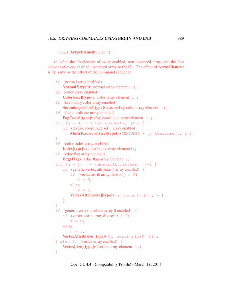
10.8. DRAWING COMMANDS USING BEGIN AND END 389
void ArrayElement( int i );
transfers the ith element of every enabled, non-instanced array, and the firstelement of every enabled, instanced array to the GL. The effect of ArrayElementis the same as the effect of the command sequence
if (normal array enabled)Normal3[type]v(normal array element i);
if (color array enabled)Color[size][type]v(color array element i);
if (secondary color array enabled)SecondaryColor3[type]v(secondary color array element i);
if (fog coordinate array enabled)FogCoord[type]v(fog coordinate array element i);
for (j = 0; j < textureUnits; j++) {if (texture coordinate set j array enabled)
MultiTexCoord[size][type]v(TEXTURE0 + j, texcoord(j, i));}if (color index array enabled)
Index[type]v(color index array element i);if (edge flag array enabled)
EdgeFlagv(edge flag array element i);for (j = 1; j < genericAttributes; j++) {
if (generic vertex attribute j array enabled) {if (vertex attrib array divisor j > 0)
k = 0;else
k = i;VertexAttrib[size][type]v(j, genattrib(j, k));
}}if (generic vertex attribute array 0 enabled) {
if (vertex attrib array divisor 0 > 0)k = 0;
elsek = i;
VertexAttrib[size][type]v(0, genattrib(0, k));} else if (vertex array enabled) {
Vertex[size][type]v(vertex array element i);}
OpenGL 4.4 (Compatibility Profile) - March 19, 2014
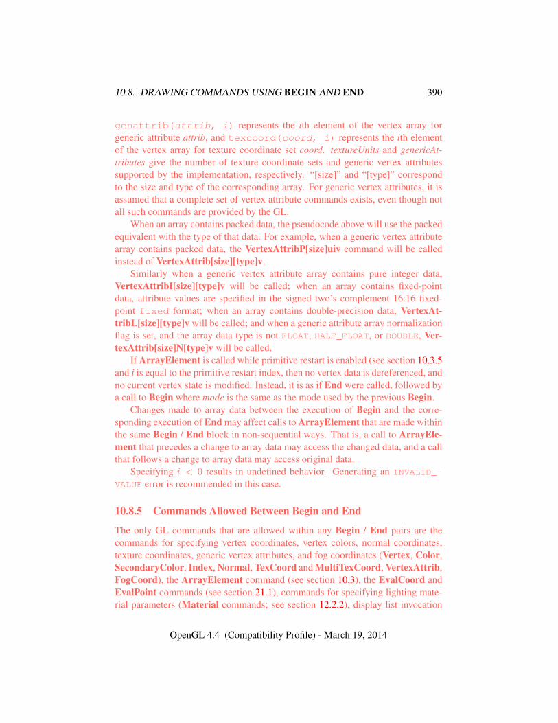
10.8. DRAWING COMMANDS USING BEGIN AND END 390
genattrib(attrib, i) represents the ith element of the vertex array forgeneric attribute attrib, and texcoord(coord, i) represents the ith elementof the vertex array for texture coordinate set coord. textureUnits and genericAt-tributes give the number of texture coordinate sets and generic vertex attributessupported by the implementation, respectively. “[size]” and “[type]” correspondto the size and type of the corresponding array. For generic vertex attributes, it isassumed that a complete set of vertex attribute commands exists, even though notall such commands are provided by the GL.
When an array contains packed data, the pseudocode above will use the packedequivalent with the type of that data. For example, when a generic vertex attributearray contains packed data, the VertexAttribP[size]uiv command will be calledinstead of VertexAttrib[size][type]v.
Similarly when a generic vertex attribute array contains pure integer data,VertexAttribI[size][type]v will be called; when an array contains fixed-pointdata, attribute values are specified in the signed two’s complement 16.16 fixed-point fixed format; when an array contains double-precision data, VertexAt-tribL[size][type]v will be called; and when a generic attribute array normalizationflag is set, and the array data type is not FLOAT, HALF_FLOAT, or DOUBLE, Ver-texAttrib[size]N[type]v will be called.
If ArrayElement is called while primitive restart is enabled (see section 10.3.5and i is equal to the primitive restart index, then no vertex data is dereferenced, andno current vertex state is modified. Instead, it is as if End were called, followed bya call to Begin where mode is the same as the mode used by the previous Begin.
Changes made to array data between the execution of Begin and the corre-sponding execution of End may affect calls to ArrayElement that are made withinthe same Begin / End block in non-sequential ways. That is, a call to ArrayEle-ment that precedes a change to array data may access the changed data, and a callthat follows a change to array data may access original data.
Specifying i < 0 results in undefined behavior. Generating an INVALID_-
VALUE error is recommended in this case.
10.8.5 Commands Allowed Between Begin and End
The only GL commands that are allowed within any Begin / End pairs are thecommands for specifying vertex coordinates, vertex colors, normal coordinates,texture coordinates, generic vertex attributes, and fog coordinates (Vertex, Color,SecondaryColor, Index, Normal, TexCoord and MultiTexCoord, VertexAttrib,FogCoord), the ArrayElement command (see section 10.3), the EvalCoord andEvalPoint commands (see section 21.1), commands for specifying lighting mate-rial parameters (Material commands; see section 12.2.2), display list invocation
OpenGL 4.4 (Compatibility Profile) - March 19, 2014
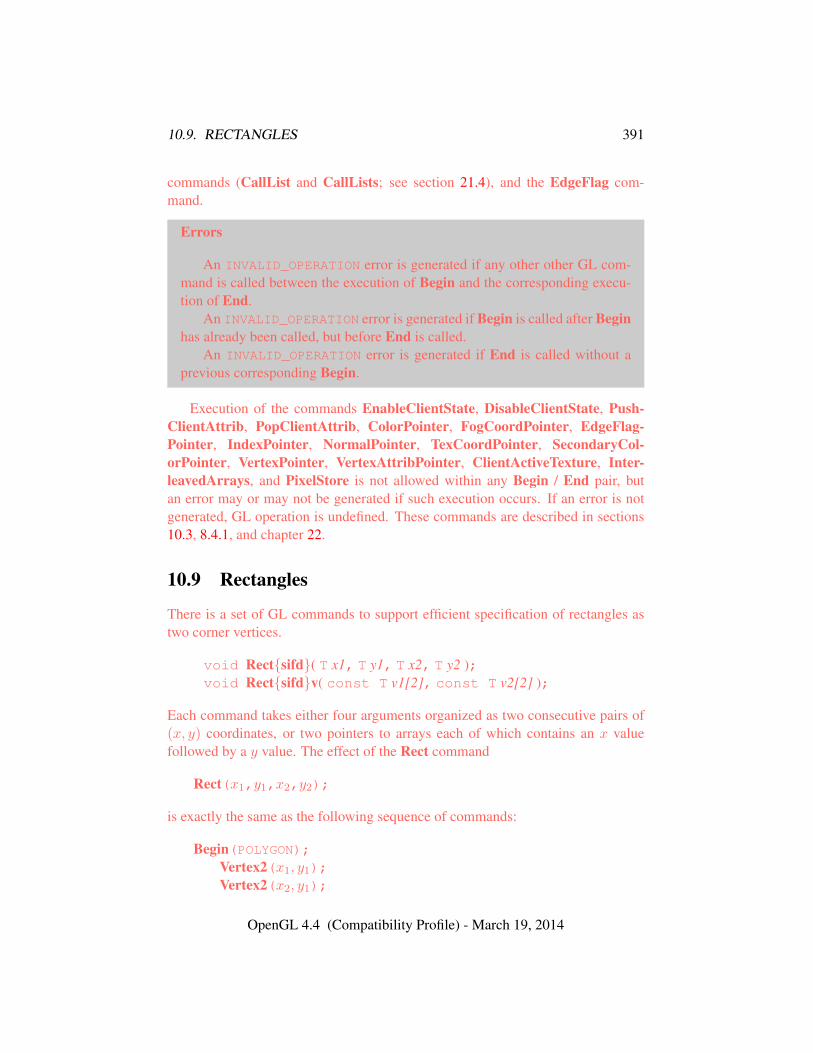
10.9. RECTANGLES 391
commands (CallList and CallLists; see section 21.4), and the EdgeFlag com-mand.
Errors
An INVALID_OPERATION error is generated if any other other GL com-mand is called between the execution of Begin and the corresponding execu-tion of End.
An INVALID_OPERATION error is generated if Begin is called after Beginhas already been called, but before End is called.
An INVALID_OPERATION error is generated if End is called without aprevious corresponding Begin.
Execution of the commands EnableClientState, DisableClientState, Push-ClientAttrib, PopClientAttrib, ColorPointer, FogCoordPointer, EdgeFlag-Pointer, IndexPointer, NormalPointer, TexCoordPointer, SecondaryCol-orPointer, VertexPointer, VertexAttribPointer, ClientActiveTexture, Inter-leavedArrays, and PixelStore is not allowed within any Begin / End pair, butan error may or may not be generated if such execution occurs. If an error is notgenerated, GL operation is undefined. These commands are described in sections10.3, 8.4.1, and chapter 22.
10.9 Rectangles
There is a set of GL commands to support efficient specification of rectangles astwo corner vertices.
void Rect{sifd}( T x1, T y1, T x2, T y2 );void Rect{sifd}v( const T v1[2], const T v2[2] );
Each command takes either four arguments organized as two consecutive pairs of(x, y) coordinates, or two pointers to arrays each of which contains an x valuefollowed by a y value. The effect of the Rect command
Rect(x1,y1,x2,y2);
is exactly the same as the following sequence of commands:
Begin(POLYGON);Vertex2(x1, y1);Vertex2(x2, y1);
OpenGL 4.4 (Compatibility Profile) - March 19, 2014
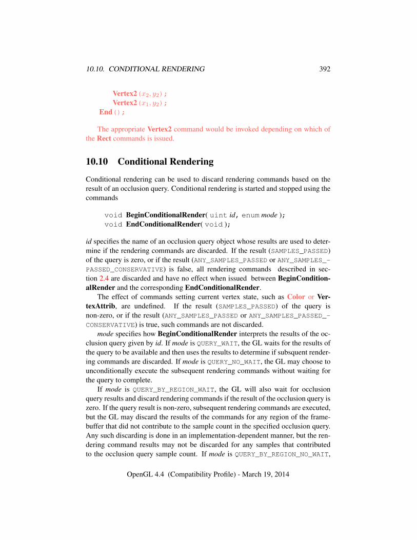
10.10. CONDITIONAL RENDERING 392
Vertex2(x2, y2);Vertex2(x1, y2);
End();
The appropriate Vertex2 command would be invoked depending on which ofthe Rect commands is issued.
10.10 Conditional Rendering
Conditional rendering can be used to discard rendering commands based on theresult of an occlusion query. Conditional rendering is started and stopped using thecommands
void BeginConditionalRender( uint id, enum mode );void EndConditionalRender( void );
id specifies the name of an occlusion query object whose results are used to deter-mine if the rendering commands are discarded. If the result (SAMPLES_PASSED)of the query is zero, or if the result (ANY_SAMPLES_PASSED or ANY_SAMPLES_-PASSED_CONSERVATIVE) is false, all rendering commands described in sec-tion 2.4 are discarded and have no effect when issued between BeginCondition-alRender and the corresponding EndConditionalRender.
The effect of commands setting current vertex state, such as Color or Ver-texAttrib, are undefined. If the result (SAMPLES_PASSED) of the query isnon-zero, or if the result (ANY_SAMPLES_PASSED or ANY_SAMPLES_PASSED_-CONSERVATIVE) is true, such commands are not discarded.
mode specifies how BeginConditionalRender interprets the results of the oc-clusion query given by id. If mode is QUERY_WAIT, the GL waits for the results ofthe query to be available and then uses the results to determine if subsquent render-ing commands are discarded. If mode is QUERY_NO_WAIT, the GL may choose tounconditionally execute the subsequent rendering commands without waiting forthe query to complete.
If mode is QUERY_BY_REGION_WAIT, the GL will also wait for occlusionquery results and discard rendering commands if the result of the occlusion query iszero. If the query result is non-zero, subsequent rendering commands are executed,but the GL may discard the results of the commands for any region of the frame-buffer that did not contribute to the sample count in the specified occlusion query.Any such discarding is done in an implementation-dependent manner, but the ren-dering command results may not be discarded for any samples that contributedto the occlusion query sample count. If mode is QUERY_BY_REGION_NO_WAIT,
OpenGL 4.4 (Compatibility Profile) - March 19, 2014
10.10. CONDITIONAL RENDERING 393
the GL operates as in QUERY_BY_REGION_WAIT, but may choose to uncondition-ally execute the subsequent rendering commands without waiting for the query tocomplete.
Errors
An INVALID_OPERATION error is generated by BeginConditionalRen-der if called while conditional rendering is in progress.
An INVALID_VALUE error is generated if id is not the name of an existingquery object.
An INVALID_OPERATION error is generated if id is the name of a queryobject with a target other SAMPLES_PASSED, ANY_SAMPLES_PASSED, orANY_SAMPLES_PASSED_CONSERVATIVE, or if id is the name of a query cur-rently in progress.
An INVALID_OPERATION error is generated by EndConditionalRenderif called while conditional rendering is not in progress,
OpenGL 4.4 (Compatibility Profile) - March 19, 2014
Chapter 11
Programmable Vertex Processing
When the program object currently in use for the vertex stage (see section 7.3)includes a vertex shader, its shader is considered active and is used to processvertices transferred to the GL (see section 11.1). Vertices may be further processedby tessellation and geometry shaders (see sections 11.2 and 11.3). The resultingtransformed vertices are then processed as described in chapter 13.
If the current vertex stage program object has no vertex shader, or no programobject is current for the vertex stage, then a fixed-function method for vertex pro-cessing is used instead. The transformation and lighting operations making up thismethod are described in chapter 12.
11.1 Vertex Shaders
Vertex shaders describe the operations that occur on vertex values and their associ-ated data. When the program object currently in use for the vertex stage includes avertex shader, its vertex shader is considered active and is used to process vertices.
Vertex attributes are per-vertex values available to vertex shaders, and are spec-ified as described in section 10.2.
11.1.1 Vertex Attributes
Vertex shaders can define named attribute variables, which are bound to genericvertex attributes transferred by drawing commands. This binding can be specifiedby the application before the program is linked, or automatically assigned by theGL when the program is linked.
Vertex shaders can also access built-in variables corresponding to conventionalvertex attributes such as vertex coordinates, normals, and colors.
394
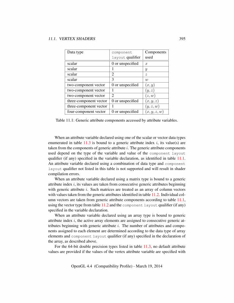
11.1. VERTEX SHADERS 395
Data type component Componentslayout qualifier used
scalar 0 or unspecified x
scalar 1 y
scalar 2 z
scalar 3 w
two-component vector 0 or unspecified (x, y)
two-component vector 1 (y, z)
two-component vector 2 (z, w)
three-component vector 0 or unspecified (x, y, z)
three-component vector 1 (y, z, w)
four-component vector 0 or unspecified (x, y, z, w)
Table 11.1: Generic attribute components accessed by attribute variables.
When an attribute variable declared using one of the scalar or vector data typesenumerated in table 11.3 is bound to a generic attribute index i, its value(s) aretaken from the components of generic attribute i. The generic attribute componentsused depend on the type of the variable and value of the component layout
qualifier (if any) specified in the variable declaration, as identified in table 11.1.An attribute variable declared using a combination of data type and component
layout qualifier not listed in this table is not supported and will result in shadercompilation errors.
When an attribute variable declared using a matrix type is bound to a genericattribute index i, its values are taken from consecutive generic attributes beginningwith generic attribute i. Such matrices are treated as an array of column vectorswith values taken from the generic attributes identified in table 11.2. Individual col-umn vectors are taken from generic attribute components according to table 11.1,using the vector type from table 11.2 and the component layout qualifier (if any)specified in the variable declaration.
When an attribute variable declared using an array type is bound to genericattribute index i, the active array elements are assigned to consecutive generic at-tributes beginning with generic attribute i. The number of attributes and compo-nents assigned to each element are determined according to the data type of arrayelements and component layout qualifier (if any) specified in the declaration ofthe array, as described above.
For the 64-bit double precision types listed in table 11.3, no default attributevalues are provided if the values of the vertex attribute variable are specified with
OpenGL 4.4 (Compatibility Profile) - March 19, 2014

11.1. VERTEX SHADERS 396
Data type Column vector type Genericlayout qualifier attributes used
mat2, dmat2 two-component vector i, i+ 1
mat2x3, dmat2x3 three-component vector i, i+ 1
mat2x4, dmat2x4 four-component vector i, i+ 1
mat3x2, dmat3x2 two-component vector i, i+ 1, i+ 2
mat3, dmat3 three-component vector i, i+ 1, i+ 2
mat3x4, dmat3x4 four-component vector i, i+ 1, i+ 2
mat4x2, dmat4x2 two-component vector i, i+ 1, i+ 2, i+ 3
mat4x3, dmat4x3 three-component vector i, i+ 1, i+ 2, i+ 3
mat4, dmat4 four-component vector i, i+ 1, i+ 2, i+ 3
Table 11.2: Generic attributes and vector types used by column vectors of matrixvariables bound to generic attribute index i.
Data type Commandint VertexAttribI1iivec2 VertexAttribI2iivec3 VertexAttribI3iivec4 VertexAttribI4iuint VertexAttribI1uiuvec2 VertexAttribI2uiuvec3 VertexAttribI3uiuvec4 VertexAttribI4uifloat VertexAttrib1*vec2 VertexAttrib2*vec3 VertexAttrib3*vec4 VertexAttrib4*double VertexAttribL1ddvec2 VertexAttribL2ddvec3 VertexAttribL3ddvec4 VertexAttribL4d
Table 11.3: Scalar and vector vertex attribute types and VertexAttrib* commandsused to set the values of the corresponding generic attribute.
OpenGL 4.4 (Compatibility Profile) - March 19, 2014
11.1. VERTEX SHADERS 397
fewer components than required for the attribute variable. For example, the fourthcomponent of a variable of type dvec4 will be undefined if specified using Ver-texAttribL3dv, or using a vertex array specified with VertexAttribLPointer anda size of three.
The command
void BindAttribLocation( uint program, uint index, constchar *name );
specifies that the attribute variable named name in program program should bebound to generic vertex attribute index when the program is next linked. If namewas bound previously, its assigned binding is replaced with index. name must bea null-terminated string. BindAttribLocation has no effect until the program islinked. In particular, it doesn’t modify the bindings of active attribute variables ina program that has already been linked.
Built-in attribute variables are automatically bound to conventional attributes,and can not have an assigned binding.
When a program is linked, any active attributes without a binding specifiedeither through BindAttribLocation or explicitly set within the shader text willautomatically be bound to vertex attributes by the GL. Such bindings can bequeried using the command GetAttribLocation. LinkProgram will fail if theassigned binding of an active attribute variable would cause the GL to referencea non-existent generic attribute (one greater than or equal to the value of MAX_-VERTEX_ATTRIBS). LinkProgram will fail if the attribute bindings specified ei-ther by BindAttribLocation or explicitly set within the shader text do not leave notenough space to assign a location for an active matrix attribute or an active attributearray, both of which require multiple contiguous generic attributes. If an activeattribute has a binding explicitly set within the shader text and a different bind-ing assigned by BindAttribLocation, the assignment in the shader text is used.LinkProgram will also fail if the vertex shaders used in the program object containassignments (not removed during pre-processing) to an attribute variable bound togeneric attribute zero and to the conventional vertex position (gl_Vertex).
BindAttribLocation may be issued before any vertex shader objects are at-tached to a program object. Hence it is allowed to bind any name (except a namestarting with "gl_") to an index, including a name that is never used as an at-tribute in any vertex shader object. Assigned bindings for attribute variables thatdo not exist or are not active are ignored.
OpenGL 4.4 (Compatibility Profile) - March 19, 2014
11.1. VERTEX SHADERS 398
Errors
An INVALID_VALUE error is generated if program is not the name of ei-ther a program or shader object.
An INVALID_OPERATION error is generated if program is the name of ashader object.
An INVALID_VALUE error is generated if index is greater than or equal tothe value of MAX_VERTEX_ATTRIBS.
An INVALID_OPERATION error is generated if name is a built-in attributevariable starting with the reserved "gl_" prefix).
To determine the set of active vertex attribute variables used by a program,applications can query the properties and active resources of the PROGRAM_INPUTinterface of a program including a vertex shader.
Additionally, the command
void GetActiveAttrib( uint program, uint index,sizei bufSize, sizei *length, int *size, enum *type,char *name );
can be used to determine properties of the active input variable assigned the indexindex in program object program. If no error occurs, the command is equivalent to
const enum props[] = { ARRAY_SIZE, TYPE };GetProgramResourceName(program, PROGRAM_INPUT,
index, bufSize, length, name);GetProgramResourceiv(program, PROGRAM_INPUT,
index, 1, &props[0], 1, NULL, size);GetProgramResourceiv(program, PROGRAM_INPUT,
index, 1, &props[1], 1, NULL, (int *)type);
For GetActiveAttrib, all active vertex shader input variables are enumerated,including the special built-in inputs gl_VertexID and gl_InstanceID.
Errors
An INVALID_VALUE error is generated if program is not the name of ei-ther a program or shader object.
An INVALID_OPERATION error is generated if program is the name of ashader object.
An INVALID_VALUE error is generated if index is not the index of anactive input variable in program.
OpenGL 4.4 (Compatibility Profile) - March 19, 2014
11.1. VERTEX SHADERS 399
An INVALID_VALUE error is generated for all values of index if programdoes not include a vertex shader, as it has no active vertex attributes.
An INVALID_VALUE error is generated if bufSize is negative.
The command
int GetAttribLocation( uint program, const char *name );
can be used to determine the location assigned to the active input variable namedname in program object program.
Errors
If program has been successfully linked but contains no vertex shader, noerror is generated but -1 will be returned.
An INVALID_VALUE error is generated if program is not the name of ei-ther a program or shader object.
An INVALID_OPERATION error is generated if program is the name of ashader object.
An INVALID_OPERATION error is generated and -1 is returned if programhas not been linked or was last linked unsuccessfully.
Otherwise, the command is equivalent to
GetProgramResourceLocation(program, PROGRAM_INPUT, name);
There is an implementation-dependent limit on the number of active attributevariables (either conventional or generic) in a vertex shader. A program with morethan the value of MAX_VERTEX_ATTRIBS active attribute variables may fail tolink, unless device-dependent optimizations are able to make the program fit withinavailable hardware resources. For the purposes of this test, attribute variables ofthe type dvec3, dvec4, dmat2x3, dmat2x4, dmat3, dmat3x4, dmat4x3, anddmat4 may count as consuming twice as many attributes as equivalent single-precision types. While these types use the same number of generic attributesas their single-precision equivalents, implementations are permitted to consumetwo single-precision vectors of internal storage for each three- or four-componentdouble-precision vector.
The values of generic attributes sent to generic attribute index i are part ofcurrent state, just like the conventional attributes. If a new program object hasbeen made active, then these values will be tracked by the GL in such a way thatthe same values will be observed by attributes in the new program object that arealso bound to index i.
OpenGL 4.4 (Compatibility Profile) - March 19, 2014
11.1. VERTEX SHADERS 400
It is possible for an application to bind more than one attribute name to thesame location. This is referred to as aliasing. This will only work if only one ofthe aliased attributes is active in the executable program, or if no path through theshader consumes more than one attribute of a set of attributes aliased to the samelocation. A link error can occur if the linker determines that every path through theshader consumes multiple aliased attributes, but implementations are not requiredto generate an error in this case. The compiler and linker are allowed to assume thatno aliasing is done, and may employ optimizations that work only in the absenceof aliasing. It is not possible to alias generic attributes with conventional ones.
11.1.2 Vertex Shader Variables
Vertex shaders can access uniforms belonging to the current program object. Lim-its on uniform storage and methods for manipulating uniforms are described insection 7.6.
Vertex shaders also have access to samplers to perform texturing operations, asdescribed in section 7.10.
11.1.2.1 Output Variables
A vertex shader may define one or more output variables or outputs (see theOpenGL Shading Language Specification).
The OpenGL Shading Language Specification also defines a set of built-in out-puts that vertex shaders can write to (see section 7.1(“Built-In Variables”) of theOpenGL Shading Language Specification). These output variables are either usedas the mechanism to communicate values to the next active stage in the vertex pro-cessing pipeline: either the tessellation control shader, the tessellation evaluationshader, the geometry shader, or the fixed-function vertex processing stages leadingto rasterization.
If the output variables are passed directly to the vertex processing stages lead-ing to rasterization, the values of all outputs are expected to be interpolated acrossthe primitive being rendered, unless flatshaded. Otherwise the values of all out-puts are collected by the primitive assembly stage and passed on to the subsequentpipeline stage once enough data for one primitive has been collected.
The number of components (individual scalar numeric values) of output vari-ables that can be written by the vertex shader, whether or not a tessellation con-trol, tessellation evaluation, or geometry shader is active, is given by the valueof the implementation-dependent constant MAX_VERTEX_OUTPUT_COMPONENTS.For the purposes of counting input and output components consumed by a shader,variables declared as vectors, matrices, and arrays will all consume multiple com-
OpenGL 4.4 (Compatibility Profile) - March 19, 2014
11.1. VERTEX SHADERS 401
ponents. Each component of variables declared as double-precision floating-pointscalars, vectors, or matrices may be counted as consuming two components.
When a program is linked, all components of any outputs written by a vertexshader will count against this limit. A program whose vertex shader writes morethan the value of MAX_VERTEX_OUTPUT_COMPONENTS components worth of out-puts may fail to link, unless device-dependent optimizations are able to make theprogram fit within available hardware resources.
Additionally, when linking a program containing only a vertex and frag-ment shader, there is a limit on the total number of components used as ver-tex shader outputs or fragment shader inputs. This limit is given by the valueof the implementation-dependent constant MAX_VARYING_COMPONENTS. Theimplementation-dependent constant MAX_VARYING_VECTORS has a value equal tothe value of MAX_VARYING_COMPONENTS divided by four. Each output variablecomponent used as either a vertex shader output or fragment shader input countsagainst this limit, except for the components of gl_Position. A program con-taining only a vertex and fragment shader that accesses more than this limit’s worthof components of outputs may fail to link, unless device-dependent optimizationsare able to make the program fit within available hardware resources.
Each program object can specify a set of output variables from one shader to berecorded in transform feedback mode (see section 13.2). The variables that can berecorded are those emitted by the first active shader, in order, from the followinglist:
• geometry shader
• tessellation evaluation shader
• tessellation control shader
• vertex shader
The set of variables to record can be specified in shader text using the xfb_-buffer, xfb_offset, or xfb_stride layout qualifiers. When recording out-put variables of each vertex in transform feedback mode, a fixed amount of mem-ory is reserved in the buffer bound to each transform feedback buffer bindingpoint. Each output variable recorded is associated with a binding point, speci-fied by the xfb_buffer layout qualifier. Each output variable is written to itsassociated transform feedback binding point at an offset specified by the xfb_-
offset layout qualifier, in basic machine units, relative to the base of the mem-ory reserved for its vertex. The amount of memory reserved in each transformfeedback binding point for a single vertex can be specified using the xfb_stride
OpenGL 4.4 (Compatibility Profile) - March 19, 2014
11.1. VERTEX SHADERS 402
layout qualifier. If no xfb_stride qualifier is specified for a binding point,the stride is derived by identifying the variable associated with the binding pointhaving the largest offset, and then adding the offset and the size of the variable,in basic machine units. If any variable associated with the binding point containsdouble-precision floating-point components, the derived stride is aligned to thenext multiple of eight basic machine units. If a binding point has no xfb_stride
qualifier and no associated output variables, its stride is zero.When no xfb_buffer, xfb_offset, or xfb_stride layout qualifiers are
specified, the set of variables to record is specified with the command
void TransformFeedbackVaryings( uint program,sizei count, const char * const *varyings,enum bufferMode );
program specifies the program object. count specifies the number of output vari-ables used for transform feedback. varyings is an array of count zero-terminatedstrings specifying the names of the outputs to use for transform feedback. The vari-ables specified in varyings can be either built-in (beginning with "gl_") or user-defined variables. Output variables are written out in the order they appear in thearray varyings. bufferMode is either INTERLEAVED_ATTRIBS or SEPARATE_-ATTRIBS, and identifies the mode used to capture the outputs when transformfeedback is active.
The variables in varyings are assigned binding points and offsets sequentially,as though each were specified using the xfb_buffer and xfb_offset layout
qualifiers. The strides associated with each binding point are derived by addingthe offset and size of the last variable associated with that binding point. Thefirst variable in varyings is assigned a binding point and offset of zero. WhenbufferMode is INTERLEAVED_ATTRIBS, each subsequent variable is assigned tothe same binding point as the previous variable and an offset equal to the sum ofthe offset and size of the previous variable. When bufferMode is SEPARATE_-
ATTRIBS, each subsequent variable is assigned to the binding point following thebinding point of the previous variable with an offset of zero.
Several special identifiers are supported when bufferMode is INTERLEAVED_-ATTRIBS. These identifiers do not identify output variables captured in transformfeedback mode, but can be used to modify the binding point and offsets assignedto subsequent variables. If a string in varyings is gl_NextBuffer, the next vari-able in varyings will be assigned to the next binding point, with an offset of zero.If a string in varyings is gl_SkipComponents1, gl_SkipComponents2, gl_-SkipComponents3, or gl_SkipComponents4, the variable is treated as as spec-ifying a one- to four-component floating-point output variable with undefined val-
OpenGL 4.4 (Compatibility Profile) - March 19, 2014
11.1. VERTEX SHADERS 403
ues. No data will be recorded for such strings, but the offset assigned to the nextvariable in varyings and the stride of the assigned binding point will be affected.
Errors
An INVALID_VALUE error is generated if program is not the name of ei-ther a program or shader object.
An INVALID_OPERATION error is generated if program is the name of ashader object.
An INVALID_VALUE error is generated if count is negative.An INVALID_ENUM error is generated if bufferMode is not SEPARATE_-
ATTRIBS or INTERLEAVED_ATTRIBS.An INVALID_VALUE error is generated if bufferMode is SEPARATE_-
ATTRIBS and count is greater than the value of the implementation-dependentlimit MAX_TRANSFORM_FEEDBACK_SEPARATE_ATTRIBS.
An INVALID_OPERATION error is generated if any pointerin varyings identifies the special names gl_NextBuffer, gl_-
SkipComponents1, gl_SkipComponents2, gl_SkipComponents3,or gl_SkipComponents4 and bufferMode is not INTERLEAVED_ATTRIBS,or if the number of gl_NextBuffer pointers in varyings is greater than orequal to the value of MAX_TRANSFORM_FEEDBACK_BUFFERS.
The state set by TransformFeedbackVaryings or using transform feedbacklayout qualifiers has no effect on the execution of the program until program issubsequently linked. When LinkProgram is called, the program is linked so thatthe values of the specified outputs for the vertices of each primitive generated bythe GL are written to one or more buffer objects. If the set of output variables torecord in transform feedback mode is specified by TransformFeedbackVaryings,a program will fail to link if:
• the count specified by TransformFeedbackVaryings is non-zero, but theprogram object has no vertex, tessellation control, tessellation evaluation, orgeometry shader;
• any variable name specified in the varyings array is not one of gl_-
NextBuffer, gl_SkipComponents1, gl_SkipComponents2, gl_-
SkipComponents3, or gl_SkipComponents4, and is not declared as abuilt-in or user-defined output variable in the shader stage whose outputscan be recorded.
• any two entries in the varyings array specify the same output variable;
OpenGL 4.4 (Compatibility Profile) - March 19, 2014

11.1. VERTEX SHADERS 404
• the total number of components to capture in any output in varyings is greaterthan the value of MAX_TRANSFORM_FEEDBACK_SEPARATE_COMPONENTSand the buffer mode is SEPARATE_ATTRIBS;
• the total number of components to capture is greater than the value ofMAX_TRANSFORM_FEEDBACK_INTERLEAVED_COMPONENTS and the buffermode is INTERLEAVED_ATTRIBS; or
• the set of outputs to capture to any single binding point includes outputs frommore than one vertex stream.
If the set of output variables to record in transform feedback mode is specifiedusing layout qualifiers, a program will fail to link if:
• any pair of variables associated with the same binding point overlap in mem-ory (where the offset of the first variable is less than or equal to the offset ofthe second, but the sum of the offset and size of the first variable is greaterthan the offset of the second);
• any binding point has a stride declared using the xfb_stride layout qual-ifier and the sum of the offset and size of any variable associated with thatbinding point exceeds the value of this stride;
• any variable containing double-precision floating-point components
– has an xfb_offset layout qualifier that is not a multiple of eight; or
– is associated with a binding point with an xfb_stride layout qualifierthat is not a multiple of eight;
• the sum of the offset and size of any variable exceeds the maximumstride supported by the implementation (four times the value of MAX_-
TRANSFORM_FEEDBACK_INTERLEAVED_COMPONENTS); or
• the xfb_stride layout qualifier for any binding point exceeds the maxi-mum stride supported by the implementation.
For transform feedback purposes, each component of outputs declared asdouble-precision floating-point scalars, vectors, or matrices are considered to con-sume eight basic machine units, and each component of any other type is consid-ered to consume four basic machine units.
To determine the set of output variables in a linked program object that willbe captured in transform feedback mode and the binding points to which those
OpenGL 4.4 (Compatibility Profile) - March 19, 2014
11.1. VERTEX SHADERS 405
variables are written, applications can query the properties and active resourcesof the TRANSFORM_FEEDBACK_VARYING and TRANSFORM_FEEDBACK_BUFFER
interfaces.If the shader used to record output variables for transform feedback varyings
uses the xfb_buffer, xfb_offset, or xfb_stride layout qualifiers, the val-ues specified by TransformFeedbackVaryings are ignored, and the set of vari-ables captured for transform feedback is instead derived from the specified layoutqualifiers.
Additionally, the command
void GetTransformFeedbackVarying( uint program,uint index, sizei bufSize, sizei *length, sizei *size,enum *type, char *name );
can be used to enumerate properties of a single output variable captured in trans-form feedback mode, and is equivalent to
const enum props[] = { ARRAY_SIZE, TYPE };GetProgramResourceName(program, TRANSFORM_FEEDBACK_VARYING,
index, bufSize, length, name);GetProgramResourceiv(program, TRANSFORM_FEEDBACK_VARYING,
index, 1, &props[0], 1, NULL, size);GetProgramResourceiv(program, TRANSFORM_FEEDBACK_VARYING,
index, 1, &props[1], 1, NULL, (int *)type);
Special output names (e.g., gl_NextBuffer, gl_SkipComponents1)passed to TransformFeedbackVaryings in the varyings array are counted as out-puts to be recorded for the purposes of determining the value of TRANSFORM_-FEEDBACK_VARYINGS and for determining the variable selected by index in Get-TransformFeedbackVarying. If index identifies gl_NextBuffer, the valueszero and NONE will be written to size and type, respectively. If index is of the formgl_SkipComponentsn, the value NONE will be written to type and the number ofcomponents n will be written to size.
GetTransformFeedbackVarying may be used to query any transform feed-back varying variable, not just those specified with TransformFeedbackVarying.
11.1.3 Shader Execution
If there is an active program object present for the vertex, tessellation control,tessellation evaluation, or geometry shader stages, the executable code for these
OpenGL 4.4 (Compatibility Profile) - March 19, 2014
11.1. VERTEX SHADERS 406
active programs is used to process incoming vertex values, instead of the fixed-function method described in chapter 12. The following sequence of operations isperformed:
• Vertices are processed by the vertex shader (see section 11.1) and assembledinto primitives as described in sections 10.1 through 10.3.
• If the current program contains a tessellation control shader, each indi-vidual patch primitive is processed by the tessellation control shader (sec-tion 11.2.1). Otherwise, primitives are passed through unmodified. If active,the tessellation control shader consumes its input patch and produces a newpatch primitive, which is passed to subsequent pipeline stages.
• If the current program contains a tessellation evaluation shader, each indi-vidual patch primitive is processed by the tessellation primitive generator(section 11.2.2) and tessellation evaluation shader (see section 11.2.3). Oth-erwise, primitives are passed through unmodified. When a tessellation eval-uation shader is active, the tessellation primitive generator produces a newcollection of point, line, or triangle primitives to be passed to subsequentpipeline stages. The vertices of these primitives are processed by the tes-sellation evaluation shader. The patch primitive passed to the tessellationprimitive generator is consumed by this process.
• If the current program contains a geometry shader, each individual primitiveis processed by the geometry shader (section 11.3). Otherwise, primitivesare passed through unmodified. If active, the geometry shader consumes itsinput patch. However, each geometry shader invocation may emit new ver-tices, which are arranged into primitives and passed to subsequent pipelinestages.
Following shader execution, the fixed-function operations described in chap-ter 13 are applied.
Special considerations for vertex shader execution are described in the follow-ing sections.
11.1.3.1 Shader Only Texturing
This section describes texture functionality that is only accessible through shaders(of all types). Also refer to chapter 8 and to section 8.9(“Texture Functions”) ofthe OpenGL Shading Language Specification,
OpenGL 4.4 (Compatibility Profile) - March 19, 2014
11.1. VERTEX SHADERS 407
11.1.3.2 Texel Fetches
The OpenGL Shading Language texel fetch functions provide the ability to ex-tract a single texel from a specified texture image. The integer coordinates passedto the texel fetch functions are used as the texel coordinates (i, j, k) into the tex-ture image. This in turn means the texture image is point-sampled (no filtering isperformed), but the remaining steps of texture access (described below) are stillapplied.
The level of detail accessed is computed by adding the specified level-of-detailparameter lod to the base level of the texture, levelbase.
The texel fetch functions can not perform depth comparisons or access cubemaps. Unlike filtered texel accesses, texel fetches do not support LOD clamping orany texture wrap mode, and require a mipmapped minification filter to access anylevel of detail other than the base level.
Texel fetches with incorrect parameters or state occur under any the followingconditions:
• the computed level of detail is less than the texture’s base level (levelbase) orgreater than the maximum defined level, q (see section 8.14.3)
• the computed level of detail is not the texture’s base level and the texture’sminification filter is NEAREST or LINEAR
• the layer specified for array textures is negative or greater than or equal tothe number of layers in the array texture
• the texel coordinates (i, j, k) refer to a texel outside the defined extents ofthe specified level of detail, where any of
i < −bs i ≥ ws − bsj < −bs j ≥ hs − bsk < −bs k ≥ ds − bs
and the size parameters bs, ws, hs, and ds refer to the border size, width,height, and depth of the image, as in equation 8.3
• the texture being accessed is not complete, as defined in section 8.17.
• the texture being accessed is not bound.
In all the above cases, if the context was created with robust buffer accessenabled (see section 10.3.6), the result of the texture fetch is zero, or a texture
OpenGL 4.4 (Compatibility Profile) - March 19, 2014
11.1. VERTEX SHADERS 408
source color of (0, 0, 0, 1) in the case of a texel fetch from an incomplete texture.If robust buffer access is not enabled, the result of the texture fetch is undefined ineach case.
11.1.3.3 Multisample Texel Fetches
Multisample buffers do not have mipmaps, and there is no level of detail parameterfor multisample texel fetches. Instead, an integer parameter selects the samplenumber to be fetched from the buffer. The number identifying the sample is thesame as the value used to query the sample location using GetMultisamplefv.Multisample textures support only NEAREST filtering.
Additionally, this fetch may only be performed on a multisample texture sam-pler. No other sample or fetch commands may be performed on a multisampletexture sampler.
11.1.3.4 Texture Queries
The OpenGL Shading Language textureSize functions provide the ability toquery the size of a texture image. The LOD value lod passed in as an argumentto the texture size functions is added to the levelbase of the texture to determinea texture image level. The dimensions of that image level, excluding a possibleborder, are then returned. If the computed texture image level is outside the range[levelbase, q], the results are undefined. When querying the size of an array texture,both the dimensions and the layer index are returned.
The OpenGL Shading Language textureQueryLevels functions providethe ability to query the number of accessible mipmap levels in a texture objectassociated with a sampler uniform. If the sampler is associated with an immutable-format texture object (see section 8.19), the value returned will be:
min{levelimmut − 1, levelmax} − levelbase + 1.
Otherwise, the value returned will be an implementation-dependent value betweenzero and q− levelbase + 1, where q is defined in section 8.14.3. The value returnedin that case must satisfy the following constraints:
• if all levels of the texture have zero size, zero must be returned
• if the texture is complete, a non-zero value must be returned
• if the texture is complete and is accessed with a minification filter requiringmipmaps, q − levelbase + 1 must be returned.
OpenGL 4.4 (Compatibility Profile) - March 19, 2014
11.1. VERTEX SHADERS 409
11.1.3.5 Texture Access
Shaders have the ability to do a lookup into a texture map. The maximum numberof texture image units available to shaders are the values of the implementation-dependent constants
• MAX_VERTEX_TEXTURE_IMAGE_UNITS (for vertex shaders),
• MAX_TESS_CONTROL_TEXTURE_IMAGE_UNITS (for tessellation controlshaders),
• MAX_TESS_EVALUATION_TEXTURE_IMAGE_UNITS (for tessellation eval-uation shaders),
• MAX_GEOMETRY_TEXTURE_IMAGE_UNITS (for geometry shaders), and
• MAX_TEXTURE_IMAGE_UNITS (for fragment shaders).
• MAX_COMPUTE_TEXTURE_IMAGE_UNITS (for compute shaders),
All active shaders, and fixed-function fragment processing if no fragmentshader is active, combined cannot use more than the value of MAX_COMBINED_-TEXTURE_IMAGE_UNITS texture image units. If more than one pipeline stageaccesses the same texture image unit, each such access counts separately againstthe MAX_COMBINED_TEXTURE_IMAGE_UNITS limit.
When a texture lookup is performed in a shader, the filtered texture value τ iscomputed in the manner described in sections 8.14 and 8.15, and converted to atexture base color Cb as shown in table 16.1, followed by application of the textureswizzle as described in section 16.1 to compute the texture source color Cs andAs.
The resulting four-component vector (Rs, Gs, Bs, As) is returned to the shader.Texture lookup functions (see section 8.9(“Texture Functions”) of the OpenGLShading Language Specification) may return floating-point, signed, or unsignedinteger values depending on the function and the internal format of the texture.
In shaders other than fragment shaders, it is not possible to perform automaticlevel-of-detail calculations using partial derivatives of the texture coordinates withrespect to window coordinates as described in section 8.14. Hence, there is no au-tomatic selection of an image array level. Minification or magnification of a texturemap is controlled by a level-of-detail value optionally passed as an argument in thetexture lookup functions. If the texture lookup function supplies an explicit level-of-detail value l, then the pre-bias level-of-detail value λbase(x, y) = l (replacingequation 8.4). If the texture lookup function does not supply an explicit level-of-detail value, then λbase(x, y) = 0. The scale factor ρ(x, y) and its approximationfunction f(x, y) (see equation 8.8) are ignored.
OpenGL 4.4 (Compatibility Profile) - March 19, 2014
11.1. VERTEX SHADERS 410
Texture lookups involving textures with depth component data generate a tex-ture base color Cb either using depth data directly or by performing a comparisonwith the Dref value used to perform the lookup, as described in section 8.23.1,and expanding the resulting value Rt to a color Cb = (Rt, 0, 0, 1). In eithercase, swizzling of Cb is then performed as described above, but only the first com-ponent Cs[0] is returned to the shader. The comparison operation is requested inthe shader by using any of the shadow sampler types (sampler*Shadow), and inthe texture using the TEXTURE_COMPARE_MODE parameter. These requests mustbe consistent; the results of a texture lookup are undefined if any of the followingconditions are true:
• The sampler used in a texture lookup function is not one of the shadow sam-pler types, the texture object’s base internal format is DEPTH_COMPONENTor DEPTH_STENCIL, and the TEXTURE_COMPARE_MODE is not NONE.
• The sampler used in a texture lookup function is one of the shadow sam-pler types, the texture object’s base internal format is DEPTH_COMPONENTor DEPTH_STENCIL, and the TEXTURE_COMPARE_MODE is NONE.
• The sampler used in a texture lookup function is one of the shadow sam-pler types, and the texture object’s base internal format is not DEPTH_-COMPONENT or DEPTH_STENCIL.
• The sampler used in a texture lookup function is one of the shadow samplertypes, the texture object’s base internal format is DEPTH_STENCIL, and theDEPTH_STENCIL_TEXTURE_MODE is not DEPTH_COMPONENT.
The stencil index texture internal component is ignored if the base internalformat is DEPTH_STENCIL and the value of DEPTH_STENCIL_TEXTURE_MODE isnot STENCIL_INDEX.
Texture lookups involving texture objects with an internal format of DEPTH_-STENCIL can read the stencil value as described in section 8.23 by settingthe DEPTH_STENCIL_TEXTURE_MODE to STENCIL_INDEX. Textures with aSTENCIL_INDEX base internal format may also be used to read stencil data. Thestencil value is read as an integer and assigned to Rt. An unsigned integer samplershould be used to lookup the stencil component, otherwise the results are unde-fined.
If a sampler is used in a shader and the sampler’s associated texture is notcomplete, as defined in section 8.17, (0, 0, 0, 1) will be returned for a non-shadowsampler and 0 for a shadow sampler.
OpenGL 4.4 (Compatibility Profile) - March 19, 2014
11.1. VERTEX SHADERS 411
11.1.3.6 Atomic Counter Access
Shaders have the ability to set and get atomic counters. The maximum number ofatomic counters available to shaders are the values of the implementation depen-dent constants
• MAX_VERTEX_ATOMIC_COUNTERS (for vertex shaders),
• MAX_TESS_CONTROL_ATOMIC_COUNTERS (for tessellation controlshaders),
• MAX_TESS_EVALUATION_ATOMIC_COUNTERS (for tessellation evaluationshaders),
• MAX_GEOMETRY_ATOMIC_COUNTERS (for geometry shaders), and
• MAX_FRAGMENT_ATOMIC_COUNTERS (for fragment shaders).
• MAX_COMPUTE_ATOMIC_COUNTERS (for compute shaders),
All active shaders combined cannot use more than the value of MAX_-
COMBINED_ATOMIC_COUNTERS atomic counters. If more than one pipeline stageaccesses the same atomic counter, each such access counts separately against theMAX_COMBINED_ATOMIC_COUNTERS limit.
11.1.3.7 Image Access
Shaders have the ability to read and write to textures using image uniforms. Themaximum number of image uniforms available to individual shader stages are thevalues of the implementation dependent constants
• MAX_VERTEX_IMAGE_UNIFORMS (vertex shaders),
• MAX_TESS_CONTROL_IMAGE_UNIFORMS (tessellation control shaders),
• MAX_TESS_EVALUATION_IMAGE_UNIFORMS (tessellation evaluationshaders),
• MAX_GEOMETRY_IMAGE_UNIFORMS (geometry shaders), and
• MAX_FRAGMENT_IMAGE_UNIFORMS (fragment shaders).
• MAX_COMPUTE_IMAGE_UNIFORMS (for compute shaders),
OpenGL 4.4 (Compatibility Profile) - March 19, 2014

11.1. VERTEX SHADERS 412
All active shaders combined cannot use more than the value of MAX_-
COMBINED_IMAGE_UNIFORMS image uniforms. If more than one shader stageaccesses the same image uniform, each such access counts separately against theMAX_COMBINED_IMAGE_UNIFORMS limit.
11.1.3.8 Shader Storage Buffer Access
Shaders have the ability to read and write to buffer memory via buffer variables inshader storage blocks. The maximum number of shader storage blocks available toshaders are the values of the implementation dependent constants
• MAX_VERTEX_SHADER_STORAGE_BLOCKS (for vertex shaders)
• MAX_TESS_CONTROL_SHADER_STORAGE_BLOCKS (for tessellation controlshaders)
• MAX_TESS_EVALUATION_SHADER_STORAGE_BLOCKS (for tessellationevaluation shaders)
• MAX_GEOMETRY_SHADER_STORAGE_BLOCKS (for geometry shaders)
• MAX_FRAGMENT_SHADER_STORAGE_BLOCKS (for fragment shaders)
• MAX_COMPUTE_SHADER_STORAGE_BLOCKS (for compute shaders)
All active shaders combined cannot use more than the value of MAX_-
COMBINED_SHADER_STORAGE_BLOCKS shader storage blocks. If more than onepipeline stage accesses the same shader storage block, each such access separatelyagainst this combined limit.
11.1.3.9 Shader Inputs
Besides having access to vertex attributes and uniform variables, vertex shaderscan access the read-only built-in variables gl_VertexID and gl_InstanceID.
gl_VertexID holds the integer index i explicitly passed to ArrayElement tospecify the vertex, or implicitly passed by DrawArrays or one of the other drawingcommands defined in section 10.5. The value of gl_VertexID is defined if andonly if:
• the vertex comes from a vertex array command that specifies a completeprimitive (a vertex array drawing command other than ArrayElement).
• all enabled vertex arrays have non-zero buffer object bindings, and
OpenGL 4.4 (Compatibility Profile) - March 19, 2014
11.1. VERTEX SHADERS 413
• the vertex does not come from a display list, even if the display list wascompiled using one of the vertex array commands described above with datasourced from buffer objects.
gl_InstanceID holds the integer instance number of the current primitive inan instanced draw call (see section 10.5).
Section 7.1(“Built-In Variables”) of the OpenGL Shading Language Specifica-tion also describes these variables.
11.1.3.10 Shader Outputs
A vertex shader can write to built-in as well as user-defined output variables. Thesevalues are expected to be interpolated across the primitive it outputs, unless theyare specified to be flat shaded. Refer to section 13.4 and sections 4.3.6(“OutputVariables”), 4.5(“Interpolation Qualifiers”), and 7.1(“Built-In Variables”) of theOpenGL Shading Language Specification for more detail.
The built-in outputs gl_FrontColor,gl_BackColor, gl_FrontSecondaryColor, and gl_BackSecondaryColor
hold the front and back colors for the primary and secondary colors for the currentvertex.
The built-in output gl_TexCoord[] is an array and holds the set of texturecoordinates for the current vertex.
The built-in output gl_FogFragCoord is used as the c value described insection 16.4.
The built-in output gl_Position is intended to hold the homogeneous vertexposition. Writing gl_Position is optional.
The built-in output variables gl_ClipVertex and gl_ClipDistance re-spectively hold the vertex coordinate and clip distance(s) used in the clipping stage,as described in section 13.5. If clipping is enabled, only one of gl_ClipVertexand gl_ClipDistance should be written.
The built-in output gl_PointSize, if written, holds the size of the point to berasterized, measured in pixels.
11.1.3.11 Position Invariance
If a vertex shader uses the built-in function ftransform to generate a vertex posi-tion, then this generally guarantees that the transformed position will be the samewhether using this vertex shader or the fixed-function pipeline. This allows for cor-rect multi-pass rendering algorithms, where some passes use fixed-function vertextransformation and other passes use a vertex shader. If a vertex shader does not use
OpenGL 4.4 (Compatibility Profile) - March 19, 2014
11.1. VERTEX SHADERS 414
ftransform to generate a position, transformed positions are not guaranteed tomatch, even if the sequence of instructions used to compute the position match thesequence of transformations described in section 12.1.
11.1.3.12 Validation
It is not always possible to determine at link time if a program object can executesuccessfully, given that LinkProgram can not know the state of the remainderof the pipeline. Therefore validation is done when the first rendering commandwhich triggers shader invocations is issued, to determine if the set of active programobjects can be executed.
An INVALID_OPERATION error is generated by any command that transfersvertices to the GL or launches compute work if the current set of active programobjects cannot be executed, for reasons including:
• A program object is active for at least one, but not all of the shader stagesthat were present when the program was linked.
• One program object is active for at least two shader stages and a secondprogram is active for a shader stage between two stages for which the firstprogram was active. The active compute shader is ignored for the purposesof this test.
• There is an active program for tessellation control, tessellation evaluation, orgeometry stages with corresponding executable shader, but there is no activeprogram with executable vertex shader.
• There is no current program object specified by UseProgram, there is a cur-rent program pipeline object, and the current program for any shader stagehas been relinked since being applied to the pipeline object via UsePro-gramStages with the PROGRAM_SEPARABLE parameter set to FALSE.
• Any two active samplers in the set of active program objects are of differenttypes, but refer to the same texture image unit.
• Any active sampler in the current program object refers to a texture imageunit where fixed-function fragment processing accesses a texture target thatdoes not match the sampler type.
• The sum of the number of active samplers in the program and the number oftexture image units enabled for fixed-function fragment processing exceedsthe combined limit on the total number of texture image units allowed.
OpenGL 4.4 (Compatibility Profile) - March 19, 2014
11.1. VERTEX SHADERS 415
• The sum of the number of active shader storage blocks used by the currentprogram objects exceeds the combined limit on the number of active shaderstorage blocks (the value of MAX_COMBINED_SHADER_STORAGE_BLOCKS).
Fixed-function fragment processing operations will be performed if the pro-gram object in use has no fragment shader.
The INVALID_OPERATION error generated by these rendering commands maynot provide enough information to find out why the currently active program objectwould not execute. No information at all is available about a program object thatwould still execute, but is inefficient or suboptimal given the current GL state. Asa development aid, use the command
void ValidateProgram( uint program );
to validate the program object program against the current GL state. Each pro-gram object has a boolean status, VALIDATE_STATUS, that is modified as a resultof validation. This status can be queried with GetProgramiv (see section 7.13).If validation succeeded this status will be set to TRUE, otherwise it will be set toFALSE. If validation succeeded, no INVALID_OPERATION validation error is gen-erated if program is made current via UseProgram, given the current state. Ifvalidation failed, such errors are generated under the current state.
ValidateProgram will check for all the conditions described in this section,and may check for other conditions as well. For example, it could give a hint onhow to optimize some piece of shader code. The information log of program isoverwritten with information on the results of the validation, which could be anempty string. The results written to the information log are typically only use-ful during application development; an application should not expect different GLimplementations to produce identical information.
A shader should not fail to compile, and a program object should not fail tolink due to lack of instruction space or lack of temporary variables. Implementa-tions should ensure that all valid shaders and program objects may be successfullycompiled, linked and executed.
Errors
An INVALID_VALUE error is generated if program is not the name of ei-ther a program or shader object.
An INVALID_OPERATION error is generated if program is the name of ashader object.
OpenGL 4.4 (Compatibility Profile) - March 19, 2014
11.1. VERTEX SHADERS 416
Separable program objects may have validation failures that cannot be detectedwithout the complete program pipeline. Mismatched interfaces, improper usageof program objects together, and the same state-dependent failures can result invalidation errors for such program objects. As a development aid, use the command
void ValidateProgramPipeline( uint pipeline );
to validate the program pipeline object pipeline against the current GL state. Eachprogram pipeline object has a boolean status, VALIDATE_STATUS, that is modifiedas a result of validation. This status can be queried with GetProgramPipelineiv(see section 7.13). If validation succeeded, no INVALID_OPERATION validationerror is generated if pipeline is bound and no program is made current via UsePro-gram, given the current state. If validation failed, such errors are generated underthe current state.
If pipeline is a name that has been generated (without subsequent deletion) byGenProgramPipelines, but refers to a program pipeline object that has not beenpreviously bound, the GL first creates a new state vector in the same manner aswhen BindProgramPipeline creates a new program pipeline object.
Errors
An INVALID_OPERATION error is generated if pipeline is not a name re-turned from a previous call to GenProgramPipelines or if such a name hassince been deleted by DeleteProgramPipelines,
11.1.3.13 Undefined Behavior
When using array or matrix variables in a shader, it is possible to access a vari-able with an index computed at run time that is outside the declared extent of thevariable. Such out-of-bounds accesses have undefined behavior, and system er-rors (possibly including program termination) may occur. The level of protectionprovided against such errors in the shader is implementation-dependent.
Robust buffer access can be enabled by creating a context with robust accessenabled through the window system binding APIs. When enabled, out-of-boundsaccesses will be bounded within the working memory of the active program andcannot access memory owned by other GL contexts, and will not result in abnormalprogram termination. Out-of-bounds access to local and global variables cannotread values from other program invocations. An out-of-bounds read may returnanother value from the active program’s working memory or zero. An out-of-bounds write may overwrite a value from the active program’s working memory orbe discarded.
OpenGL 4.4 (Compatibility Profile) - March 19, 2014
11.2. TESSELLATION 417
Out-of-bounds accesses to resources backed by buffer objects cannot read ormodify data outside of the buffer object. For resources bound to buffer ranges, ac-cess is restricted within the buffer object from which the buffer range was created,and not within the buffer range itself. Out-of-bounds reads may return values fromwithin the buffer object or zero. Out-of-bounds writes may modify values withinthe buffer object or be discarded.
Out-of-bounds accesses to arrays of resources, such as an array of textures, canonly access the data of bound resources. Reads from unbound resources returnzero and writes are discarded. It is not possible to access data owned by other GLcontexts.
Applications that require defined behavior for out-of-bounds accesses shouldrange check all computed indices before dereferencing the array, vector or matrix.
11.2 Tessellation
Tessellation is a process that reads a patch primitive and generates new primitivesused by subsequent pipeline stages. The generated primitives are formed by sub-dividing a single triangle or quad primitive according to fixed or shader-computedlevels of detail and transforming each of the vertices produced during this subdivi-sion.
Tessellation functionality is controlled by two types of tessellation shaders: tes-sellation control shaders and tessellation evaluation shaders. Tessellation is con-sidered active if and only if there is an active tessellation control or tessellationevaluation program object.
The tessellation control shader is used to read an input patch provided by theapplication, and emit an output patch. The tessellation control shader is run oncefor each vertex in the output patch and computes the attributes of that vertex. Addi-tionally, the tessellation control shader may compute additional per-patch attributesof the output patch. The most important per-patch outputs are the tessellation lev-els, which are used to control the number of subdivisions performed by the tessella-tion primitive generator. The tessellation control shader may also write additionalper-patch attributes for use by the tessellation evaluation shader. If no tessellationcontrol shader is active, the patch provided is passed through to the tessellationprimitive generator stage unmodified.
If a tessellation evaluation shader is active, the tessellation primitive generatorsubdivides a triangle or quad primitive into a collection of points, lines, or trianglesaccording to the tessellation levels of the patch and the set of layout declarationsspecified in the tessellation evaluation shader text. The tessellation levels used tocontrol subdivision are normally written by the tessellation control shader. If no
OpenGL 4.4 (Compatibility Profile) - March 19, 2014
11.2. TESSELLATION 418
tessellation control shader is active, default tessellation levels are instead used.When a tessellation evaluation shader is active, it is run on each vertex gener-
ated by the tessellation primitive generator to compute the final position and otherattributes of the vertex. The tessellation evaluation shader can read the relativelocation of the vertex in the subdivided output primitive, given by an (u, v) or(u, v, w) coordinate, as well as the position and attributes of any or all of the ver-tices in the input patch.
Tessellation operates only on patch primitives.An INVALID_OPERATION error is generated by any command that transfers
vertices to the GL if tessellation is active and the primitive mode is not PATCHES.Patch primitives are not supported by pipeline stages below the tessellation
evaluation shader.An INVALID_OPERATION error is generated by any command that transfers
vertices to the GL if the primitive mode is PATCHES and there is no active tessella-tion evaluation program .
A non-separable program object or program pipeline object that includes atessellation shader of any kind must also include a vertex shader.
Errors
An INVALID_OPERATION error is generated by any command that trans-fers vertices to the GL if the current program state has a tessellation shader butno vertex shader.
11.2.1 Tessellation Control Shaders
The tessellation control shader consumes an input patch provided by the applica-tion and emits a new output patch. The input patch is an array of vertices with at-tributes corresponding to output variables written by the vertex shader. The outputpatch consists of an array of vertices with attributes corresponding to per-vertexoutput variables written by the tessellation control shader and a set of per-patchattributes corresponding to per-patch output variables written by the tessellationcontrol shader. Tessellation control output variables are per-vertex by default, butmay be declared as per-patch using the patch qualifier.
The number of vertices in the output patch is fixed when the program is linked,and is specified in tessellation control shader source code using the output layoutqualifier vertices, as described in the OpenGL Shading Language Specification.A program will fail to link if the output patch vertex count is not specified byany tessellation control shader object attached to the program, if it is specifieddifferently by multiple tessellation control shader objects, if it is less than or equal
OpenGL 4.4 (Compatibility Profile) - March 19, 2014
11.2. TESSELLATION 419
to zero, or if it is greater than the implementation-dependent maximum patch size.The output patch vertex count may be queried by calling GetProgramiv with thesymbolic constant TESS_CONTROL_OUTPUT_VERTICES.
Tessellation control shaders are created as described in section 7.1, using a typeof TESS_CONTROL_SHADER. When a new input patch is received, the tessellationcontrol shader is run once for each vertex in the output patch. The tessellation con-trol shader invocations collectively specify the per-vertex and per-patch attributesof the output patch. The per-vertex attributes are obtained from the per-vertexoutput variables written by each invocation. Each tessellation control shader in-vocation may only write to per-vertex output variables corresponding to its ownoutput patch vertex. The output patch vertex number corresponding to a giventessellation control point shader invocation is given by the built-in variable gl_-InvocationID. Per-patch attributes are taken from the per-patch output variables,which may be written by any tessellation control shader invocation. While tessella-tion control shader invocations may read any per-vertex and per-patch output vari-able and write any per-patch output variable, reading or writing output variablesalso written by other invocations has ordering hazards discussed below.
11.2.1.1 Tessellation Control Shader Variables
Tessellation control shaders can access uniforms belonging to the current programobject. Limits on uniform storage and methods for manipulating uniforms aredescribed in section 7.6.
Tessellation control shaders also have access to samplers to perform texturingoperations, as described in section 7.10.
Tessellation control shaders can access the transformed attributes of all verticesfor their input primitive using input variables. A vertex shader writing to outputvariables generates the values of these input variables. Values for any inputs thatare not written by a vertex shader are undefined.
Additionally, tessellation control shaders can write to one or more output vari-ables including per-vertex attributes for the vertices of the output patch and per-patch attributes of the patch. Tessellation control shaders can also write to a setof built-in per-vertex and per-patch outputs defined in the OpenGL Shading Lan-guage. The per-vertex and per-patch attributes of the output patch are used by thetessellation primitive generator (section 11.2.2) and may be read by tessellationcontrol shader (section 11.2.3).
OpenGL 4.4 (Compatibility Profile) - March 19, 2014
11.2. TESSELLATION 420
11.2.1.2 Tessellation Control Shader Execution Environment
If there is an active program for the tessellation control stage, the executable ver-sion of the program’s tessellation control shader is used to process patches result-ing from the primitive assembly stage. When tessellation control shader execu-tion completes, the input patch is consumed. A new patch is assembled from theper-vertex and per-patch output variables written by the shader and is passed tosubsequent pipeline stages.
There are several special considerations for tessellation control shader execu-tion described in the following sections.
11.2.1.2.1 Texture Access Section 11.1.3.1 describes texture lookup function-ality accessible to a vertex shader. The texel fetch and texture size query function-ality described there also applies to tessellation control shaders.
11.2.1.2.2 Tessellation Control Shader Inputs Section 7.1(“Built-In Vari-ables”) of the OpenGL Shading Language Specification describes the built-invariable array gl_in available as input to a tessellation control shader. gl_-
in receives values from equivalent built-in output variables written by the ver-tex shader (section 11.1.3). Each array element of gl_in is a structure holdingvalues for a specific vertex of the input patch. The length of gl_in is equal tothe implementation-dependent maximum patch size (gl_MaxPatchVertices).Behavior is undefined if gl_in is indexed with a vertex index greater thanor equal to the current patch size. The members of each element of thegl_in array are gl_Position, gl_PointSize, gl_ClipDistance, gl_-
ClipVertex, gl_FrontColor, gl_BackColor, gl_FrontSecondaryColor,gl_BackSecondaryColor, gl_TexCoord, and gl_FogFragCoord.
Tessellation control shaders have available several other built-in input variablesnot replicated per-vertex and not contained in gl_in, including:
• The variable gl_PatchVerticesIn holds the number of vertices in theinput patch being processed by the tessellation control shader.
• The variable gl_PrimitiveID is filled with the number of primitives pro-cessed since the last time Begin was called (directly or indirectly via ver-tex array functions). The first primitive generated after a Begin is num-bered zero, and the primitive ID counter is incremented after every individualpoint, line, or triangle primitive is processed. Restarting a primitive topologyusing the primitive restart index has no effect on the primitive ID counter.
OpenGL 4.4 (Compatibility Profile) - March 19, 2014
11.2. TESSELLATION 421
• The variable gl_InvocationID holds an invocation number for the cur-rent tessellation control shader invocation. Tessellation control shaders areinvoked once per output patch vertex, and invocations are numbered begin-ning with zero.
Similarly to the built-in inputs, each user-defined input variable has a valuefor each vertex and thus needs to be declared as arrays or inside input blocksdeclared as arrays. Declaring an array size is optional. If no size is specified,it will be taken from the implementation-dependent maximum patch size (gl_-MaxPatchVertices). If a size is specified, it must match the maximum patchsize; otherwise, a link error will occur. Since the array size may be larger thanthe number of vertices found in the input patch, behavior is undefined if a per-vertex input variable is accessed using an index greater than or equal to the numberof vertices in the input patch. The OpenGL Shading Language doesn’t supportmulti-dimensional arrays; therefore, user-defined tessellation control shader inputscorresponding to vertex shader outputs declared as arrays must be declared as arraymembers of an input block that is itself declared as an array.
Similarly to the limit on vertex shader output components (see sec-tion 11.1.2.1), there is a limit on the number of components of input variablesthat can be read by the tessellation control shader, given by the value of theimplementation-dependent constant MAX_TESS_CONTROL_INPUT_COMPONENTS.
When a program is linked, all components of any input variable read by a tes-sellation control shader will count against this limit. A program whose tessellationcontrol shader exceeds this limit may fail to link, unless device-dependent opti-mizations are able to make the program fit within available hardware resources.
Component counting rules for different variable types and variable declarationsare the same as for MAX_VERTEX_OUTPUT_COMPONENTS. (see section 11.1.2.1).
11.2.1.2.3 Tessellation Control Shader Outputs Section 7.1(“Built-In Vari-ables”) of the OpenGL Shading Language Specification describes the built-invariable array gl_out available as an output for a tessellation control shader.gl_out passes values to equivalent built-in input variables read by subsequentshader stages or to subsequent fixed functionality vertex processing pipelinestages. Each array element of gl_out is a structure holding values for a spe-cific vertex of the output patch. The length of gl_out is equal to the outputpatch size specified in the tessellation control shader output layout declaration.The members of each element of the gl_out array are gl_Position, gl_-PointSize, gl_ClipDistance, gl_ClipVertex, gl_FrontColor, gl_-
BackColor, gl_FrontSecondaryColor, gl_BackSecondaryColor, gl_-
OpenGL 4.4 (Compatibility Profile) - March 19, 2014
11.2. TESSELLATION 422
TexCoord, and gl_FogFragCoord, and behave identically to equivalentlynamed vertex shader outputs (section 11.1.3).
Tessellation shaders additionally have two built-in per-patch output arrays,gl_TessLevelOuter and gl_TessLevelInner. These arrays are not repli-cated for each output patch vertex and are not members of gl_out. gl_-
TessLevelOuter is an array of four floating-point values specifying the approxi-mate number of segments that the tessellation primitive generator should use whensubdividing each outer edge of the primitive it subdivides. gl_TessLevelInneris an array of two floating-point values specifying the approximate number of seg-ments used to produce a regularly-subdivided primitive interior. The values writ-ten to gl_TessLevelOuter and gl_TessLevelInner need not be integers, andtheir interpretation depends on the type of primitive the tessellation primitive gener-ator will subdivide and other tessellation parameters, as discussed in the followingsection.
A tessellation control shader may also declare user-defined per-vertex outputvariables. User-defined per-vertex output variables are declared with the qualifierout and have a value for each vertex in the output patch. Such variables must bedeclared as arrays or inside output blocks declared as arrays. Declaring an arraysize is optional. If no size is specified, it will be taken from the output patch sizedeclared in the shader. If a size is specified, it must match the maximum patchsize; otherwise, a link error will occur. The OpenGL Shading Language doesn’tsupport multi-dimensional arrays; therefore, user-defined per-vertex tessellationcontrol shader outputs with multiple elements per vertex must be declared as arraymembers of an output block that is itself declared as an array.
While per-vertex output variables are declared as arrays indexed by vertexnumber, each tessellation control shader invocation may write only to those out-puts corresponding to its output patch vertex. Tessellation control shaders mustuse the input variable gl_InvocationID as the vertex number index when writ-ing to per-vertex output variables.
Additionally, a tessellation control shader may declare per-patch output vari-ables using the qualifier patch out. Unlike per-vertex outputs, per-patch outputsdo not correspond to any specific vertex in the patch, and are not indexed by vertexnumber. Per-patch outputs declared as arrays have multiple values for the outputpatch; similarly declared per-vertex outputs would indicate a single value for eachvertex in the output patch. User-defined per-patch outputs are not used by the tes-sellation primitive generator, but may be read by tessellation evaluation shaders.
There are several limits on the number of components of output variables thatcan be written by the tessellation control shader. The number of componentsof active per-vertex output variables may not exceed the value of MAX_TESS_-CONTROL_OUTPUT_COMPONENTS. The number of components of active per-patch
OpenGL 4.4 (Compatibility Profile) - March 19, 2014
11.2. TESSELLATION 423
output variables may not exceed the value of MAX_TESS_PATCH_COMPONENTS.The built-in outputs gl_TessLevelOuter and gl_TessLevelInner are notcounted against the per-patch limit. The total number of components of active per-vertex and per-patch outputs is derived by multiplying the per-vertex output com-ponent count by the output patch size and then adding the per-patch output compo-nent count. The total component count may not exceed MAX_TESS_CONTROL_-
TOTAL_OUTPUT_COMPONENTS.When a program is linked, all components of any output variable written by a
tessellation control shader will count against this limit. A program exceeding anyof these limits may fail to link, unless device-dependent optimizations are able tomake the program fit within available hardware resources.
Counting rules for different variable types and variable declarations are thesame as for MAX_VERTEX_OUTPUT_COMPONENTS. (see section 11.1.2.1).
11.2.1.2.4 Tessellation Control Shader Execution Order For tessellationcontrol shaders with a declared output patch size greater than one, the shader isinvoked more than once for each input patch. The order of execution of one tessel-lation control shader invocation relative to the other invocations for the same inputpatch is largely undefined. The built-in function barrier provides some controlover relative execution order. When a tessellation control shader calls the barrierfunction, its execution pauses until all other invocations have also called the samefunction. Output variable assignments performed by any invocation executed priorto calling barrier will be visible to any other invocation after the call to barrierreturns. Shader output values read in one invocation but written by another maybe undefined without proper use of barrier; full rules are found in the OpenGLShading Language Specification.
The barrier function may only be called inside the main entry point of thetessellation control shader and may not be called in potentially divergent flow con-trol. In particular, barrier may not be called inside a switch statement, in eithersub-statement of an if statement, inside a do, for, or while loop, or at any point aftera return statement in the function main.
11.2.2 Tessellation Primitive Generation
If a tessellation evaluation shader is present, the tessellation primitive generatorconsumes the input patch and produces a new set of basic primitives (points, lines,or triangles). These primitives are produced by subdividing a geometric primitive(rectangle or triangle) according to the per-patch tessellation levels written by thetessellation control shader, if present, or taken from default patch parameter val-
OpenGL 4.4 (Compatibility Profile) - March 19, 2014
11.2. TESSELLATION 424
ues. This subdivision is performed in an implementation-dependent manner. If notessellation evaluation shader is present, the tessellation primitive generator passesincoming primitives through without modification.
The type of subdivision performed by the tessellation primitive generator isspecified by an input layout declaration in the tessellation evaluation shader us-ing one of the identifiers triangles, quads, and isolines. For triangles,the primitive generator subdivides a triangle primitive into smaller triangles. Forquads, the primitive generator subdivides a rectangle primitive into smaller tri-angles. For isolines, the primitive generator subdivides a rectangle primitiveinto a collection of line segments arranged in strips stretching horizontally acrossthe rectangle. Each vertex produced by the primitive generator has an associated(u, v, w) or (u, v) position in a normalized parameter space, with parameter valuesin the range [0, 1], as illustrated in figure 11.1. For triangles, the vertex positionis a barycentric coordinate (u, v, w), where u+ v +w = 1, and indicates the rela-tive influence of the three vertices of the triangle on the position of the vertex. Forquads and isolines, the position is a (u, v) coordinate indicating the relativehorizontal and vertical position of the vertex relative to the subdivided rectangle.The subdivision process is explained in more detail in subsequent sections.
When no tessellation control shader is present, the tessellation levels are takenfrom default patch tessellation levels. These default levels are set by calling
void PatchParameterfv( enum pname, constfloat *values );
If pname is PATCH_DEFAULT_OUTER_LEVEL, values specifies an array of fourfloating-point values corresponding to the four outer tessellation levels for eachsubsequent patch. If pname is PATCH_DEFAULT_INNER_LEVEL, values specifiesan array of two floating-point values corresponding to the two inner tessellationlevels.
A patch is discarded by the tessellation primitive generator if any relevant outertessellation level is less than or equal to zero. Patches will also be discarded ifany relevant outer tessellation level corresponds to a floating-point NaN (not anumber) in implementations supporting NaN. When patches are discarded, no newprimitives will be generated and the tessellation evaluation program will not be run.For quads, all four outer levels are relevant. For triangles and isolines, onlythe first three or two outer levels, respectively, are relevant. Negative inner levelswill not cause a patch to be discarded; they will be clamped as described below.
Each of the tessellation levels is used to determine the number and spacingof segments used to subdivide a corresponding edge. The method used to derivethe number and spacing of segments is specified by an input layout declaration
OpenGL 4.4 (Compatibility Profile) - March 19, 2014
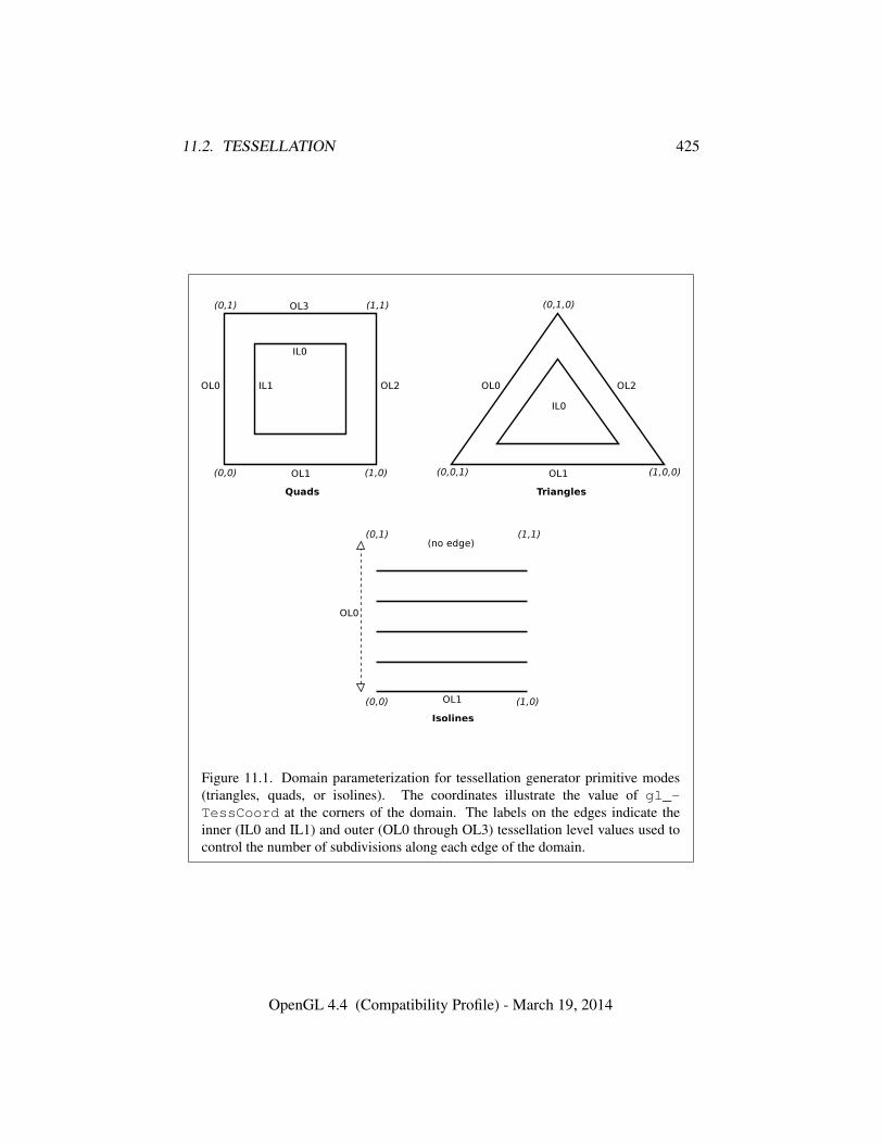
11.2. TESSELLATION 425
Figure 11.1. Domain parameterization for tessellation generator primitive modes(triangles, quads, or isolines). The coordinates illustrate the value of gl_-TessCoord at the corners of the domain. The labels on the edges indicate theinner (IL0 and IL1) and outer (OL0 through OL3) tessellation level values used tocontrol the number of subdivisions along each edge of the domain.
OpenGL 4.4 (Compatibility Profile) - March 19, 2014
11.2. TESSELLATION 426
in the tessellation evaluation shader using one of the identifiers equal_spacing,fractional_even_spacing, or fractional_odd_spacing. If no spacing isspecified in the tessellation evaluation shader, equal_spacing will be used.
If equal_spacing is used, the floating-point tessellation level is first clampedto the range [1,max], where max is the implementation-dependent maximum tes-sellation level (the value of MAX_TESS_GEN_LEVEL). The result is rounded up tothe nearest integer n, and the corresponding edge is divided into n segments ofequal length in (u, v) space.
If fractional_even_spacing is used, the tessellation level is first clampedto the range [2,max] and then rounded up to the nearest even integer n. Iffractional_odd_spacing is used, the tessellation level is clamped to the range[1,max− 1] and then rounded up to the nearest odd integer n. If n is one, the edgewill not be subdivided. Otherwise, the corresponding edge will be divided inton − 2 segments of equal length, and two additional segments of equal length thatare typically shorter than the other segments. The length of the two additional seg-ments relative to the others will decrease monotonically with the value of n − f ,where f is the clamped floating-point tessellation level. When n − f is zero, theadditional segments will have equal length to the other segments. As n − f ap-proaches 2.0, the relative length of the additional segments approaches zero. Thetwo additional segments should be placed symmetrically on opposite sides of thesubdivided edge. The relative location of these two segments is undefined, butmust be identical for any pair of subdivided edges with identical values of f .
When the tessellation primitive generator produces triangles (in thetriangles or quads modes), the orientation of all triangles can be specified byan input layout declaration in the tessellation evaluation shader using the identi-fiers cw and ccw. If the order is cw, the vertices of all generated triangles will havea clockwise ordering in (u, v) or (u, v, w) space, as illustrated in figure 11.1. If theorder is ccw, the vertices will be specified in counter-clockwise order. If no layoutis specified, ccw will be used.
For all primitive modes, the tessellation primitive generator is capable of gen-erating points instead of lines or triangles. If an input layout declaration in thetessellation evaluation shader specifies the identifier point_mode, the primitivegenerator will generate one point for each unique vertex produced by tessellation.Otherwise, the primitive generator will produce a collection of line segments ortriangles according to the primitive mode.
The points, lines, or triangles produced by the tessellation primitive generatorare passed to subsequent pipeline stages in an implementation-dependent order.
OpenGL 4.4 (Compatibility Profile) - March 19, 2014
11.2. TESSELLATION 427
Errors
An INVALID_ENUM error is generated if pname is not PATCH_DEFAULT_-OUTER_LEVEL or PATCH_DEFAULT_INNER_LEVEL.
11.2.2.1 Triangle Tessellation
If the tessellation primitive mode is triangles, an equilateral triangle is subdi-vided into a collection of triangles covering the area of the original triangle. First,the original triangle is subdivided into a collection of concentric equilateral trian-gles. The edges of each of these triangles are subdivided, and the area betweeneach triangle pair is filled by triangles produced by joining the vertices on the sub-divided edges. The number of concentric triangles and the number of subdivisionsalong each triangle except the outermost is derived from the first inner tessellationlevel. The edges of the outermost triangle are subdivided independently, using thefirst, second, and third outer tessellation levels to control the number of subdivi-sions of the u = 0 (left), v = 0 (bottom), and w = 0 (right) edges, respectively.The second inner tessellation level and the fourth outer tessellation level have noeffect in this mode.
If the first inner tessellation level and all three outer tessellation levels are ex-actly one after clamping and rounding, only a single triangle with (u, v, w) co-ordinates of (0, 0, 1), (1, 0, 0), and (0, 1, 0) is generated. If the inner tessellationlevel is one and any of the outer tessellation levels is greater than one, the innertessellation level is treated as though it were originally specified as 1 + ε and willbe rounded up to result in a two- or three-segment subdivision according to thetessellation spacing.
If any tessellation level is greater than one, tessellation begins by producing aset of concentric inner triangles and subdividing their edges. First, the three outeredges are temporarily subdivided using the clamped and rounded first inner tes-sellation level and the specified tessellation spacing, generating n segments. Forthe outermost inner triangle, the inner triangle is degenerate – a single point at thecenter of the triangle – if n is two. Otherwise, for each corner of the outer trian-gle, an inner triangle corner is produced at the intersection of two lines extendedperpendicular to the corner’s two adjacent edges running through the vertex of thesubdivided outer edge nearest that corner. If n is three, the edges of the inner tri-angle are not subdivided and is the final triangle in the set of concentric triangles.Otherwise, each edge of the inner triangle is divided into n − 2 segments, withthe n− 1 vertices of this subdivision produced by intersecting the inner edge withlines perpendicular to the edge running through the n− 1 innermost vertices of thesubdivision of the outer edge. Once the outermost inner triangle is subdivided, the
OpenGL 4.4 (Compatibility Profile) - March 19, 2014
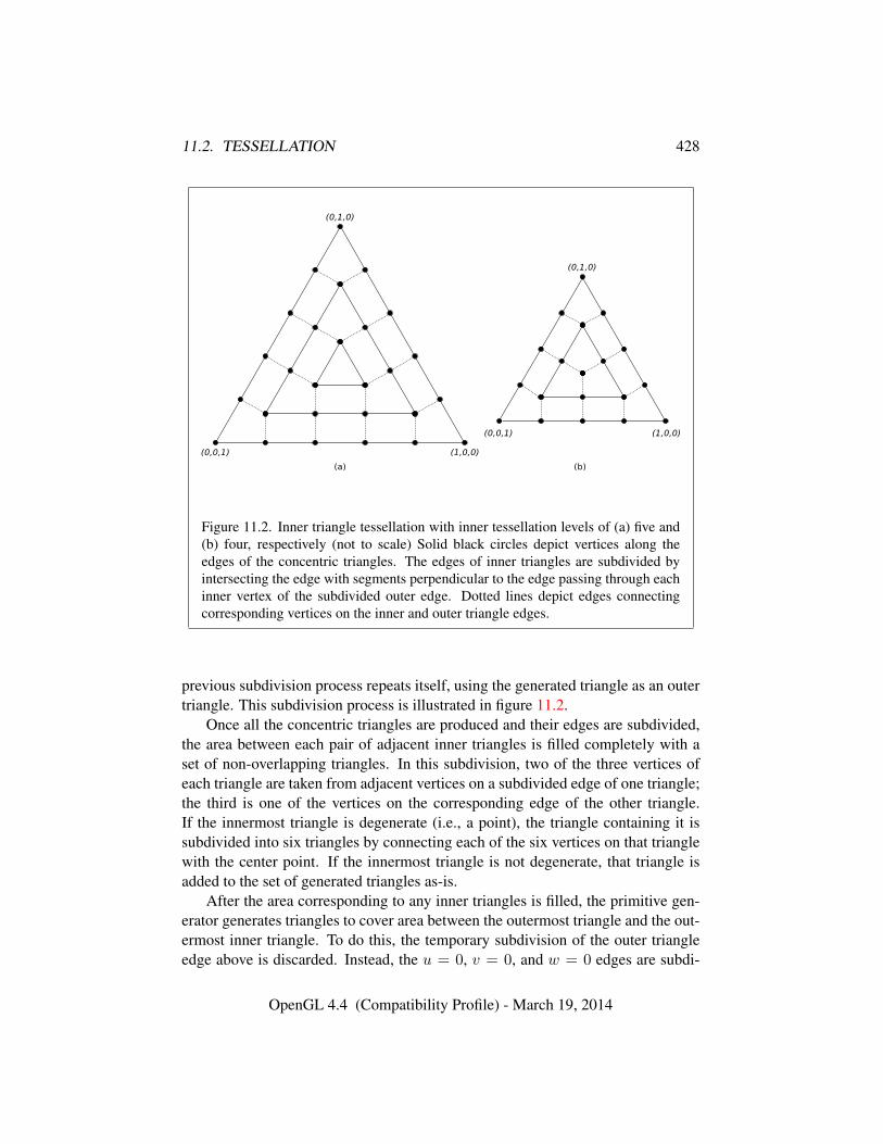
11.2. TESSELLATION 428
Figure 11.2. Inner triangle tessellation with inner tessellation levels of (a) five and(b) four, respectively (not to scale) Solid black circles depict vertices along theedges of the concentric triangles. The edges of inner triangles are subdivided byintersecting the edge with segments perpendicular to the edge passing through eachinner vertex of the subdivided outer edge. Dotted lines depict edges connectingcorresponding vertices on the inner and outer triangle edges.
previous subdivision process repeats itself, using the generated triangle as an outertriangle. This subdivision process is illustrated in figure 11.2.
Once all the concentric triangles are produced and their edges are subdivided,the area between each pair of adjacent inner triangles is filled completely with aset of non-overlapping triangles. In this subdivision, two of the three vertices ofeach triangle are taken from adjacent vertices on a subdivided edge of one triangle;the third is one of the vertices on the corresponding edge of the other triangle.If the innermost triangle is degenerate (i.e., a point), the triangle containing it issubdivided into six triangles by connecting each of the six vertices on that trianglewith the center point. If the innermost triangle is not degenerate, that triangle isadded to the set of generated triangles as-is.
After the area corresponding to any inner triangles is filled, the primitive gen-erator generates triangles to cover area between the outermost triangle and the out-ermost inner triangle. To do this, the temporary subdivision of the outer triangleedge above is discarded. Instead, the u = 0, v = 0, and w = 0 edges are subdi-
OpenGL 4.4 (Compatibility Profile) - March 19, 2014
11.2. TESSELLATION 429
vided according to the first, second, and third outer tessellation levels, respectively,and the tessellation spacing. The original subdivision of the first inner triangle isretained. The area between the outer and first inner triangles is completely filled bynon-overlapping triangles as described above. If the first (and only) inner triangleis degenerate, a set of triangles is produced by connecting each vertex on the outertriangle edges with the center point.
After all triangles are generated, each vertex in the subdivided triangle is as-signed a barycentric (u, v, w) coordinate based on its location relative to the threevertices of the outer triangle.
The algorithm used to subdivide the triangular domain in (u, v, w) space intoindividual triangles is implementation-dependent. However, the set of trianglesproduced will completely cover the domain, and no portion of the domain will becovered by multiple triangles. The order in which the generated triangles passedto subsequent pipeline stages and the order of the vertices in those triangles areboth implementation-dependent. However, when depicted in a manner similar tofigure 11.2, the order of the vertices in the generated triangles will be either allclockwise or all counter-clockwise, according to the vertex order layout declara-tion.
11.2.2.2 Quad Tessellation
If the tessellation primitive mode is quads, a rectangle is subdivided into a col-lection of triangles covering the area of the original rectangle. First, the originalrectangle is subdivided into a regular mesh of rectangles, where the number ofrectangles along the u = 0 and u = 1 (vertical) and v = 0 and v = 1 (horizon-tal) edges are derived from the first and second inner tessellation levels, respec-tively. All rectangles, except those adjacent to one of the outer rectangle edges,are decomposed into triangle pairs. The outermost rectangle edges are subdividedindependently, using the first, second, third, and fourth outer tessellation levels tocontrol the number of subdivisions of the u = 0 (left), v = 0 (bottom), u = 1(right), and v = 1 (top) edges, respectively. The area between the inner rectan-gles of the mesh and the outer rectangle edges are filled by triangles produced byjoining the vertices on the subdivided outer edges to the vertices on the edge of theinner rectangle mesh.
If both clamped inner tessellation levels and all four clamped outer tessellationlevels are exactly one, only a single triangle pair covering the outer rectangle isgenerated. Otherwise, if either clamped inner tessellation level is one, that tessel-lation level is treated as though it were originally specified as 1 + ε, which wouldrounded up to result in a two- or three-segment subdivision according to the tessel-lation spacing.
OpenGL 4.4 (Compatibility Profile) - March 19, 2014
11.2. TESSELLATION 430
If any tessellation level is greater than one, tessellation begins by subdividingthe u = 0 and u = 1 edges of the outer rectangle into m segments using theclamped and rounded first inner tessellation level and the tessellation spacing. Thev = 0 and v = 1 edges are subdivided into n segments using the second innertessellation level. Each vertex on the u = 0 and v = 0 edges are joined with thecorresponding vertex on the u = 1 and v = 1 edges to produce a set of verticaland horizontal lines that divide the rectangle into a grid of smaller rectangles. Theprimitive generator emits a pair of non-overlapping triangles covering each suchrectangle not adjacent to an edge of the outer rectangle. The boundary of the re-gion covered by these triangles forms an inner rectangle, the edges of which aresubdivided by the grid vertices that lie on the edge. If either m or n is two, theinner rectangle is degenerate, and one or both of the rectangle’s “edges” consist ofa single point. This subdivision is illustrated in figure 11.3.
After the area corresponding to the inner rectangle is filled, the primitive gen-erator must produce triangles to cover area between the inner and outer rectangles.To do this, the subdivision of the outer rectangle edge above is discarded. Instead,the u = 0, v = 0, u = 1, and v = 1 edges are subdivided according to thefirst, second, third, and fourth outer tessellation levels, respectively, and the tes-sellation spacing. The original subdivision of the inner rectangle is retained. Thearea between the outer and inner rectangles is completely filled by non-overlappingtriangles. Two of the three vertices of each triangle are adjacent vertices on a sub-divided edge of one rectangle; the third is one of the vertices on the correspondingedge of the other triangle. If either edge of the innermost rectangle is degenerate,the area near the corresponding outer edges is filled by connecting each vertex onthe outer edge with the single vertex making up the inner “edge”.
The algorithm used to subdivide the rectangular domain in (u, v) space intoindividual triangles is implementation-dependent. However, the set of trianglesproduced will completely cover the domain, and no portion of the domain will becovered by multiple triangles. The order in which the generated triangles passedto subsequent pipeline stages and the order of the vertices in those triangles areboth implementation-dependent. However, when depicted in a manner similar tofigure 11.3, the order of the vertices in the generated triangles will be either allclockwise or all counter-clockwise, according to the vertex order layout declara-tion.
11.2.2.3 Isoline Tessellation
If the tessellation primitive mode is isolines, a set of independent horizontal linesegments is drawn. The segments are arranged into connected strips called isolines,where the vertices of each isoline have a constant v coordinate and u coordinates
OpenGL 4.4 (Compatibility Profile) - March 19, 2014
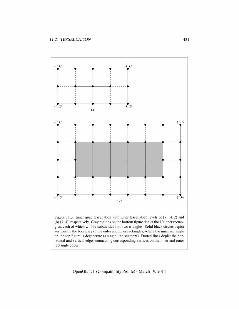
11.2. TESSELLATION 431
Figure 11.3. Inner quad tessellation with inner tessellation levels of (a) (4, 2) and(b) (7, 4), respectively. Gray regions on the bottom figure depict the 10 inner rectan-gles, each of which will be subdivided into two triangles. Solid black circles depictvertices on the boundary of the outer and inner rectangles, where the inner rectangleon the top figure is degenerate (a single line segment). Dotted lines depict the hor-izontal and vertical edges connecting corresponding vertices on the inner and outerrectangle edges.
OpenGL 4.4 (Compatibility Profile) - March 19, 2014
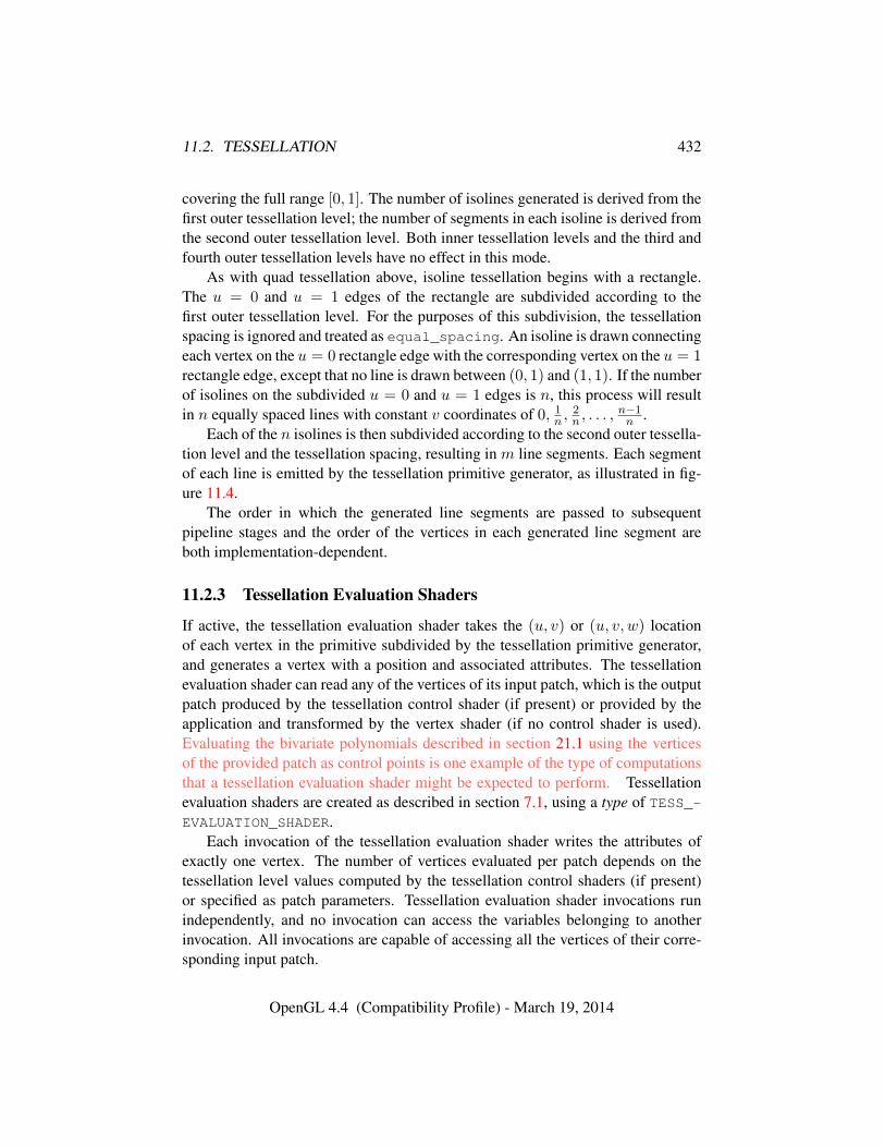
11.2. TESSELLATION 432
covering the full range [0, 1]. The number of isolines generated is derived from thefirst outer tessellation level; the number of segments in each isoline is derived fromthe second outer tessellation level. Both inner tessellation levels and the third andfourth outer tessellation levels have no effect in this mode.
As with quad tessellation above, isoline tessellation begins with a rectangle.The u = 0 and u = 1 edges of the rectangle are subdivided according to thefirst outer tessellation level. For the purposes of this subdivision, the tessellationspacing is ignored and treated as equal_spacing. An isoline is drawn connectingeach vertex on the u = 0 rectangle edge with the corresponding vertex on the u = 1rectangle edge, except that no line is drawn between (0, 1) and (1, 1). If the numberof isolines on the subdivided u = 0 and u = 1 edges is n, this process will resultin n equally spaced lines with constant v coordinates of 0, 1n ,
2n , . . . ,
n−1n .
Each of the n isolines is then subdivided according to the second outer tessella-tion level and the tessellation spacing, resulting in m line segments. Each segmentof each line is emitted by the tessellation primitive generator, as illustrated in fig-ure 11.4.
The order in which the generated line segments are passed to subsequentpipeline stages and the order of the vertices in each generated line segment areboth implementation-dependent.
11.2.3 Tessellation Evaluation Shaders
If active, the tessellation evaluation shader takes the (u, v) or (u, v, w) locationof each vertex in the primitive subdivided by the tessellation primitive generator,and generates a vertex with a position and associated attributes. The tessellationevaluation shader can read any of the vertices of its input patch, which is the outputpatch produced by the tessellation control shader (if present) or provided by theapplication and transformed by the vertex shader (if no control shader is used).Evaluating the bivariate polynomials described in section 21.1 using the verticesof the provided patch as control points is one example of the type of computationsthat a tessellation evaluation shader might be expected to perform. Tessellationevaluation shaders are created as described in section 7.1, using a type of TESS_-EVALUATION_SHADER.
Each invocation of the tessellation evaluation shader writes the attributes ofexactly one vertex. The number of vertices evaluated per patch depends on thetessellation level values computed by the tessellation control shaders (if present)or specified as patch parameters. Tessellation evaluation shader invocations runindependently, and no invocation can access the variables belonging to anotherinvocation. All invocations are capable of accessing all the vertices of their corre-sponding input patch.
OpenGL 4.4 (Compatibility Profile) - March 19, 2014
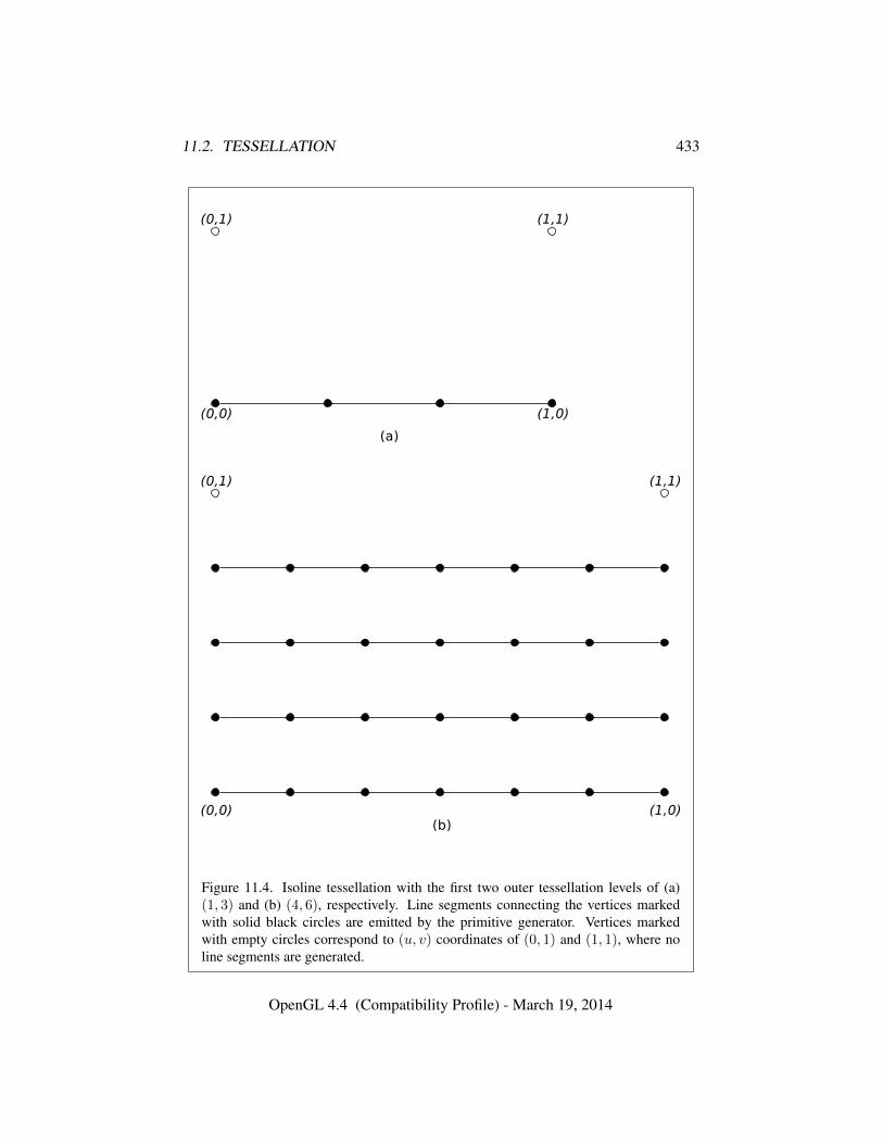
11.2. TESSELLATION 433
Figure 11.4. Isoline tessellation with the first two outer tessellation levels of (a)(1, 3) and (b) (4, 6), respectively. Line segments connecting the vertices markedwith solid black circles are emitted by the primitive generator. Vertices markedwith empty circles correspond to (u, v) coordinates of (0, 1) and (1, 1), where noline segments are generated.
OpenGL 4.4 (Compatibility Profile) - March 19, 2014
11.2. TESSELLATION 434
If a tessellation control shader is present, the number of the vertices in theinput patch is fixed and is equal to the tessellation control shader output patch sizeparameter in effect when the program was last linked. If no tessellation controlshader is present, the input patch is provided by the application can have a variablenumber of vertices, as specified by PatchParameteri.
11.2.3.1 Tessellation Evaluation Shader Variables
Tessellation evaluation shaders can access uniforms belonging to the current pro-gram object. Limits on uniform storage and methods for manipulating uniformsare described in section 7.6.
Tessellation evaluation shaders also have access to samplers to perform textur-ing operations, as described in section 7.10.
Tessellation evaluation shaders can access the transformed attributes of all ver-tices for their input primitive using input variables. If active, a tessellation controlshader writing to output variables generates the values of these input variables. Ifno tessellation control shader is active, input variables will be obtained from vertexshader outputs. Values for any input variable that are not written by a vertex ortessellation control shader are undefined.
Additionally, tessellation evaluation shaders can write to one or more outputvariables that will be passed to subsequent programmable shader stages or fixedfunctionality vertex pipeline stages.
11.2.3.2 Tessellation Evaluation Shader Execution Environment
If there is an active program for the tessellation evaluation stage, the executableversion of the program’s tessellation evaluation shader is used to process verticesproduced by the tessellation primitive generator. During this processing, the shadermay access the input patch processed by the primitive generator. When tessellationevaluation shader execution completes, a new vertex is assembled from the outputvariables written by the shader and is passed to subsequent pipeline stages.
There are several special considerations for tessellation evaluation shader exe-cution described in the following sections.
11.2.3.2.1 Texture Access Section 11.1.3.1 describes texture lookup function-ality accessible to a vertex shader. The texel fetch and texture size query function-ality described there also applies to tessellation evaluation shaders.
OpenGL 4.4 (Compatibility Profile) - March 19, 2014
11.2. TESSELLATION 435
11.2.3.3 Tessellation Evaluation Shader Inputs
Section 7.1(“Built-In Variables”) of the OpenGL Shading Language Specificationdescribes the built-in variable array gl_in available as input to a tessellation evalu-ation shader. gl_in receives values from equivalent built-in output variables writ-ten by a previous shader (section 11.1.3). If a tessellation control shader is active,the values of gl_in will be taken from tessellation control shader outputs. Other-wise, they will be taken from vertex shader outputs. Each array element of gl_inis a structure holding values for a specific vertex of the input patch. The lengthof gl_in is equal to the implementation-dependent maximum patch size (gl_-MaxPatchVertices). Behavior is undefined if gl_in is indexed with a vertex in-dex greater than or equal to the current patch size. The members of each element ofthe gl_in array are gl_Position, gl_PointSize, gl_ClipDistance, gl_-ClipVertex, gl_FrontColor, gl_BackColor, gl_FrontSecondaryColor,gl_BackSecondaryColor, gl_TexCoord, and gl_FogFragCoord.
Tessellation evaluation shaders have available several other built-in input vari-ables not replicated per-vertex and not contained in gl_in, including:
• The variables gl_PatchVerticesIn and gl_PrimitiveID are filledwith the number of the vertices in the input patch and a primitive number,respectively. They behave exactly as the identically named inputs for tessel-lation control shaders.
• The variable gl_TessCoord is a three-component floating-point vectorconsisting of the (u, v, w) coordinate of the vertex being processed by thetessellation evaluation shader. The values of u, v, and w are in the range[0, 1], and vary linearly across the primitive being subdivided. For tessella-tion primitive modes of quads or isolines, the w value is always zero.The (u, v, w) coordinates are generated by the tessellation primitive gen-erator in a manner dependent on the primitive mode, as described in sec-tion 11.2.2. gl_TessCoord is not an array; it specifies the location of thevertex being processed by the tessellation evaluation shader, not of any ver-tex in the input patch.
• The variables gl_TessLevelOuter and gl_TessLevelInner are ar-rays holding outer and inner tessellation levels of the patch, as used bythe tessellation primitive generator. If a tessellation control shader is ac-tive, the tessellation levels will be taken from the corresponding outputs ofthe tessellation control shader. Otherwise, the default levels provided aspatch parameters are used. Tessellation level values loaded in these vari-ables will be prior to the clamping and rounding operations performed by
OpenGL 4.4 (Compatibility Profile) - March 19, 2014
11.2. TESSELLATION 436
the primitive generator as described in section 11.2.2. For triangular tes-sellation, gl_TessLevelOuter[3] and gl_TessLevelInner[1] willbe undefined. For isoline tessellation, gl_TessLevelOuter[2], gl_-TessLevelOuter[3], and both values in gl_TessLevelInner are un-defined.
A tessellation evaluation shader may also declare user-defined per-vertex inputvariables. User-defined per-vertex input variables are declared with the qualifierin and have a value for each vertex in the input patch. User-defined per-vertexinput variables have a value for each vertex and thus need to be declared as arraysor inside input blocks declared as arrays. Declaring an array size is optional. Ifno size is specified, it will be taken from the implementation-dependent maximumpatch size (gl_MaxPatchVertices). If a size is specified, it must match themaximum patch size; otherwise, a link error will occur. Since the array size maybe larger than the number of vertices found in the input patch, behavior is undefinedif a per-vertex input variable is accessed using an index greater than or equal to thenumber of vertices in the input patch. The OpenGL Shading Language doesn’tsupport multi-dimensional arrays; therefore, user-defined tessellation evaluationshader inputs corresponding to shader outputs declared as arrays must be declaredas array members of an input block that is itself declared as an array.
Additionally, a tessellation evaluation shader may declare per-patch input vari-ables using the qualifier patch in. Unlike per-vertex inputs, per-patch inputs donot correspond to any specific vertex in the patch, and are not indexed by vertexnumber. Per-patch inputs declared as arrays have multiple values for the inputpatch; similarly declared per-vertex inputs would indicate a single value for eachvertex in the output patch. User-defined per-patch input variables are filled withcorresponding per-patch output values written by the tessellation control shader. Ifno tessellation control shader is active, all such variables are undefined.
Similarly to the limit on vertex shader output components (see sec-tion 11.1.2.1), there is a limit on the number of components of per-vertex andper-patch input variables that can be read by the tessellation evaluation shader,given by the values of the implementation-dependent constants MAX_TESS_-
EVALUATION_INPUT_COMPONENTS and MAX_TESS_PATCH_COMPONENTS, re-spectively. The built-in inputs gl_TessLevelOuter and gl_TessLevelInner
are not counted against the per-patch limit.When a program is linked, all components of any input variable read by a tes-
sellation evaluation shader will count against this limit. A program whose tessella-tion evaluation shader exceeds this limit may fail to link, unless device-dependentoptimizations are able to make the program fit within available hardware resources.
Component counting rules for different variable types and variable declarations
OpenGL 4.4 (Compatibility Profile) - March 19, 2014
11.3. GEOMETRY SHADERS 437
are the same as for MAX_VERTEX_OUTPUT_COMPONENTS. (see section 11.1.2.1).
11.2.3.4 Tessellation Evaluation Shader Outputs
Tessellation evaluation shaders have a number of built-in output variables usedto pass values to equivalent built-in input variables read by subsequent shaderstages or to subsequent fixed functionality vertex processing pipeline stages.These variables are gl_Position, gl_PointSize, gl_ClipDistance, gl_-ClipVertex, gl_FrontColor, gl_BackColor, gl_FrontSecondaryColor,gl_BackSecondaryColor, gl_TexCoord, and gl_FogFragCoord, and allbehave identically to equivalently named vertex shader outputs (see section 11.1.3).A tessellation evaluation shader may also declare user-defined per-vertex outputvariables.
Similarly to the limit on vertex shader output components (see sec-tion 11.1.2.1), there is a limit on the number of components of output output vari-ables that can be written by the tessellation evaluation shader, given by the valuesof the implementation-dependent constant MAX_TESS_EVALUATION_OUTPUT_-COMPONENTS.
When a program is linked, all components of any output variable written bya tessellation evaluation shader will count against this limit. A program whosetessellation evaluation shader exceeds this limit may fail to link, unless device-dependent optimizations are able to make the program fit within available hardwareresources.
Counting rules for different variable types and variable declarations are thesame as for MAX_VERTEX_OUTPUT_COMPONENTS. (see section 11.1.2.1).
11.3 Geometry Shaders
After vertices are processed, they are arranged into primitives, as described in sec-tion 10.8. This section describes optional geometry shaders, an additional pipelinestage defining operations to further process those primitives. Geometry shaders op-erate on a single primitive at a time and emit one or more output primitives, all ofthe same type, which are then processed like an equivalent OpenGL primitive spec-ified by the application. The original primitive is discarded after geometry shaderexecution. The inputs available to a geometry shader are the transformed attributesof all the vertices that belong to the primitive. Additional adjacency primitives areavailable which also make the transformed attributes of neighboring vertices avail-able to the shader. The results of the shader are a new set of transformed vertices,arranged into primitives by the shader.
OpenGL 4.4 (Compatibility Profile) - March 19, 2014
11.3. GEOMETRY SHADERS 438
The geometry shader pipeline stage is inserted after primitive assembly, priorto transform feedback (section 13.2).
A geometry shader only applies when the GL is in RGBA mode. Its operationin color index mode is undefined.
Geometry shaders are created as described in section 7.1 using a type ofGEOMETRY_SHADER. They are attached to and used in program objects as describedin section 7.3. When the program object currently in use includes a geometryshader, its geometry shader is considered active, and is used to process primitives.If the program object has no geometry shader, or no program object is in use, thisstage is bypassed.
A non-separable program object or program pipeline object that includes ageometry shader must also include a vertex shader.
Errors
An INVALID_OPERATION error is generated by any command that trans-fers vertices to the GL if the current program state has a geometry shader butno vertex shader.
11.3.1 Geometry Shader Input Primitives
A geometry shader can operate on one of five input primitive types. Depending onthe input primitive type, one to six input vertices are available when the shader isexecuted. Each input primitive type supports a subset of the primitives provided bythe GL.
An INVALID_OPERATION error is generated by any command that transfersvertices to the GL if a geometry shader is active and the primitive mode parameteris incompatible with the input primitive type of the geometry shader of the activegeometry program object, as discussed below.
A geometry shader that accesses more input vertices than are available for agiven input primitive type can be successfully compiled, because the input prim-itive type is not part of the shader object. However, a program object containinga shader object that accesses more input vertices than are available for the inputprimitive type of the program object will not link.
The input primitive type is specified in the geometry shader source code usingan input layout qualifier, as described in the OpenGL Shading Language Speci-fication. A program will fail to link if the input primitive type is not specified byany geometry shader object attached to the program, or if it is specified differentlyby multiple geometry shader objects. The input primitive type may be queried bycalling GetProgramiv with the symbolic constant GEOMETRY_INPUT_TYPE. The
OpenGL 4.4 (Compatibility Profile) - March 19, 2014
11.3. GEOMETRY SHADERS 439
supported types and the corresponding OpenGL Shading Language input layoutqualifier keywords are:
Points (points)Geometry shaders that operate on points are valid only for the POINTS primi-
tive type. There is only a single vertex available for each geometry shader invoca-tion.
Lines (lines)Geometry shaders that operate on line segments are valid only for the LINES,
LINE_STRIP, and LINE_LOOP primitive types. There are two vertices availablefor each geometry shader invocation. The first vertex refers to the vertex at thebeginning of the line segment and the second vertex refers to the vertex at the endof the line segment. See also section 11.3.4.
Lines with Adjacency (lines_adjacency)Geometry shaders that operate on line segments with adjacent vertices are valid
only for the LINES_ADJACENCY and LINE_STRIP_ADJACENCY primitive types.There are four vertices available for each program invocation. The second vertexrefers to attributes of the vertex at the beginning of the line segment and the thirdvertex refers to the vertex at the end of the line segment. The first and fourthvertices refer to the vertices adjacent to the beginning and end of the line segment,respectively.
Triangles (triangles)Geometry shaders that operate on triangles are valid for the TRIANGLES,
TRIANGLE_STRIP and TRIANGLE_FAN primitive types. There are three verticesavailable for each program invocation. The first, second and third vertices refer toattributes of the first, second and third vertex of the triangle, respectively.
Triangles with Adjacency (triangles_adjacency)Geometry shaders that operate on triangles with adjacent vertices are valid
for the TRIANGLES_ADJACENCY and TRIANGLE_STRIP_ADJACENCY primitivetypes. There are six vertices available for each program invocation. The first, thirdand fifth vertices refer to attributes of the first, second and third vertex of the tri-angle, respectively. The second, fourth and sixth vertices refer to attributes of thevertices adjacent to the edges from the first to the second vertex, from the secondto the third vertex, and from the third to the first vertex, respectively.
OpenGL 4.4 (Compatibility Profile) - March 19, 2014
11.3. GEOMETRY SHADERS 440
11.3.2 Geometry Shader Output Primitives
A geometry shader can generate primitives of one of three types. The supportedoutput primitive types are points (POINTS), line strips (LINE_STRIP), and trianglestrips (TRIANGLE_STRIP). The vertices output by the geometry shader are assem-bled into points, lines, or triangles based on the output primitive type in the mannerdescribed in section 10.8. The resulting primitives are then further processed as de-scribed in section 11.3.4. If the number of vertices emitted by the geometry shaderis not sufficient to produce a single primitive, nothing is drawn. The number ofvertices output by the geometry shader is limited to a maximum count specified inthe shader.
The output primitive type and maximum output vertex count are specified inthe geometry shader source code using an output layout qualifier, as describedin section 4.4.2.2(“Geometry Outputs”) of the OpenGL Shading Language Speci-fication. A program will fail to link if either the output primitive type or maximumoutput vertex count are not specified by any geometry shader object attached tothe program, or if they are specified differently by multiple geometry shader ob-jects. The output primitive type and maximum output vertex count of a linkedprogram may be queried by calling GetProgramiv with the symbolic constantsGEOMETRY_OUTPUT_TYPE and GEOMETRY_VERTICES_OUT, respectively.
11.3.3 Geometry Shader Variables
Geometry shaders can access uniforms belonging to the current program object.Limits on uniform storage and methods for manipulating uniforms are described insection 7.6.
Geometry shaders also have access to samplers to perform texturing operations,as described in section 7.10.
Geometry shaders can access the transformed attributes of all vertices for theirinput primitive type using input variables. A vertex shader writing to output vari-ables generates the values of these input variables. Values for any inputs that arenot written by a vertex shader are undefined. Additionally, a geometry shader hasaccess to a built-in input that holds the ID of the current primitive. This ID is gen-erated by the primitive assembly stage that sits in between the vertex and geometryshader.
Additionally, geometry shaders can write to one or more output variables foreach vertex they output. These values are optionally flatshaded (using the OpenGLShading Language qualifier flat) and clipped, then the clipped values interpo-lated across the primitive (if not flatshaded). The results of these interpolations areavailable to the fragment shader, if one is active. Geometry shaders can also write
OpenGL 4.4 (Compatibility Profile) - March 19, 2014
11.3. GEOMETRY SHADERS 441
to a set of built-in output variables defined in the OpenGL Shading Language, cor-responding to the values required for fixed-function processing that occurs aftergeometry processing.
11.3.4 Geometry Shader Execution Environment
If there is an active program for the geometry stage, the executable version ofthe program’s geometry shader is used to process primitives resulting from theprimitive assembly stage.
There are several special considerations for geometry shader execution de-scribed in the following sections.
11.3.4.1 Texture Access
Section 11.1.3.1 describes texture lookup functionality accessible to a vertexshader. The texel fetch and texture size query functionality described there alsoapplies to geometry shaders.
11.3.4.2 Instanced Geometry Shaders
For each input primitive received by the geometry shader pipeline stage, the ge-ometry shader may be run once or multiple times. The number of times a geom-etry shader should be executed for each input primitive may be specified using alayout qualifier in a geometry shader of a linked program. If the invocation countis not specified in any layout qualifier, the invocation count will be one.
Each separate geometry shader invocation is assigned a unique invocation num-ber. For a geometry shader with N invocations, each input primitive spawns Ninvocations, numbered 0 throughN−1. The built-in uniform gl_InvocationID
may be used by a geometry shader invocation to determine its invocation number.When executing instanced geometry shaders, the output primitives generated
from each input primitive are passed to subsequent pipeline stages using the shaderinvocation number to order the output. The first primitives received by the subse-quent pipeline stages are those emitted by the shader invocation numbered zero,followed by those from the shader invocation numbered one, and so forth. Addi-tionally, all output primitives generated from a given input primitive are passed tosubsequent pipeline stages before any output primitives generated from subsequentinput primitives.
OpenGL 4.4 (Compatibility Profile) - March 19, 2014
11.3. GEOMETRY SHADERS 442
11.3.4.3 Geometry Shader Vertex Streams
Geometry shaders may emit primitives to multiple independent vertex streams.Each vertex emitted by the geometry shader is directed at one of the vertex streams.As vertices are received on each stream, they are arranged into primitives of thetype specified by the geometry shader output primitive type. The shading languagebuilt-in functions EndPrimitive and EndStreamPrimitive may be used toend the primitive being assembled on a given vertex stream and start a new emptyprimitive of the same type. If an implementation supports N vertex streams, theindividual streams are numbered 0 through N − 1. There is no requirement on theorder of the streams to which vertices are emitted, and the number of vertices emit-ted to each stream may be completely independent, subject only to implementation-dependent output limits.
The primitives emitted to all vertex streams are passed to the transform feed-back stage to be captured and written to buffer objects in the manner specifiedby the transform feedback state. The primitives emitted to all streams but streamzero are discarded after transform feedback. Primitives emitted to stream zero arepassed to subsequent pipeline stages for clipping, rasterization, and subsequentfragment processing.
Geometry shaders that emit vertices to multiple vertex streams are currentlylimited to using only the points output primitive type. A program will fail tolink if it includes a geometry shader that calls the EmitStreamVertex built-infunction and has any other output primitive type parameter.
11.3.4.4 Geometry Shader Inputs
Section 7.1(“Built-In Variables”) of the OpenGL Shading Language Specificationdescribes the built-in variable array gl_in[] available as input to a geometryshader. gl_in[] receives values from equivalent built-in output variables writ-ten by the vertex shader, and each array element of gl_in[] is a structure holdingvalues for a specific vertex of the input primitive. The length of gl_in[] is de-termined by the geometry shader input type (see section 11.3.1). The members ofeach element of the gl_in[] array are:
• Structure member gl_ClipDistance[] holds the per-vertex array of clipdistances, as written by the vertex shader to its built-in output variable gl_-ClipDistance[].
• Structure member gl_ClipVertex holds the per-vertex position in clip co-ordinates, as written by the vertex shader to its built-in output variable gl_-ClipVertex.
OpenGL 4.4 (Compatibility Profile) - March 19, 2014
11.3. GEOMETRY SHADERS 443
• Structure members gl_FrontColor, gl_BackColor, gl_-
FrontSecondaryColor and gl_BackSecondaryColor hold theper-vertex front and back colors of the primary and secondary colors, aswritten by the vertex shader to the corresponding built-in output variables.
• Structure member gl_FogFragCoord holds the per-vertex fog coordi-nate, as written by the vertex shader to its built-in output variable gl_-
FogFragCoord.
• Structure member gl_TexCoord[] holds the per-vertex array of texture co-ordinates written by the vertex shader to its built-in output variable gl_-
TexCoord[].
• Structure member gl_PointSize holds the per-vertex point size writtenby the vertex shader to its built-in output variable gl_PointSize. If thevertex shader does not write gl_PointSize, the value of gl_PointSizeis undefined, regardless of the value of the enable PROGRAM_POINT_SIZE.
• Structure member gl_Position holds the per-vertex position, as writtenby the vertex shader to its built-in output variable gl_Position. Note thatwriting to gl_Position from either the vertex or geometry shader is op-tional (also see section 7.1(“Built-In Variables”) of the OpenGL ShadingLanguage Specification)
Geometry shaders also have available the built-in input variable gl_-
PrimitiveIDIn, which is not an array and has no vertex shader equivalent. Itis filled with the number of primitives processed since the last time Begin wascalled (directly or indirectly via vertex array functions). The first primitive gener-ated after a Begin is numbered zero, and the primitive ID counter is incrementedafter every individual point, line, or triangle primitive is processed. For trianglesdrawn in point or line mode, the primitive ID counter is incremented only once,even though multiple points or lines may eventually be drawn. Restarting a prim-itive topology using the primitive restart index has no effect on the primitive IDcounter.
Similarly to the built-in inputs, each user-defined input has a value for eachvertex and thus needs to be declared as arrays or inside input blocks declared asarrays. Declaring an array size is optional. If no size is specified, it will be inferredby the linker from the input primitive type. If a size is specified, it must match thenumber of vertices for the input primitive type; otherwise, a link error will occur.The OpenGL Shading Language doesn’t support multi-dimensional arrays; there-fore, user-defined geometry shader inputs corresponding to vertex shader outputs
OpenGL 4.4 (Compatibility Profile) - March 19, 2014
11.3. GEOMETRY SHADERS 444
declared as arrays must be declared as array members of an input block that is it-self declared as an array. See section 4.3.6(“Output Variables”) and chapter 7 ofthe OpenGL Shading Language Specification for more information.
Similarly to the limit on vertex shader output components (see sec-tion 11.1.2.1), there is a limit on the number of components of input variablesthat can be read by the geometry shader, given by the value of the implementation-dependent constant MAX_GEOMETRY_INPUT_COMPONENTS.
When a program is linked, all components of any input read by a geometryshader will count against this limit. A program whose geometry shader exceedsthis limit may fail to link, unless device-dependent optimizations are able to makethe program fit within available hardware resources.
Component counting rules for different variable types and variable declarationsare the same as for MAX_VERTEX_OUTPUT_COMPONENTS. (see section 11.1.2.1).
11.3.4.5 Geometry Shader Outputs
A geometry shader is limited in the number of vertices it may emit per invocation.The maximum number of vertices a geometry shader can possibly emit is spec-ified in the geometry shader source and may be queried after linking by callingGetProgramiv with the symbolic constant GEOMETRY_VERTICES_OUT. If a sin-gle invocation of a geometry shader emits more vertices than this value, the emittedvertices may have no effect.
There are two implementation-dependent limits on the value of GEOMETRY_-VERTICES_OUT; it may not exceed the value of MAX_GEOMETRY_OUTPUT_-
VERTICES, and the product of the total number of vertices and the sum of allcomponents of all active output variables may not exceed the value of MAX_-
GEOMETRY_TOTAL_OUTPUT_COMPONENTS. LinkProgram will fail if it deter-mines that the total component limit would be violated.
A geometry shader can write to built-in as well as user-defined output variables.These values are expected to be interpolated across the primitive it outputs, unlessthey are specified to be flat shaded. To enable seamlessly inserting or removing ageometry shader from a program object, the rules, names and types of the built-inand user-defined output variables are the same as for the vertex shader. Refer tosection 11.1.2.1, and to sections 4.3(“Storage Qualifiers”) and 7.1(“Built-In Vari-ables”) of the OpenGL Shading Language Specification for more detail.
After a geometry shader emits a vertex, all output variables are undefined, asdescribed in section 8.15(“Geometry Shader Functions”) of the OpenGL ShadingLanguage Specification.
The built-in outputs gl_FrontColor,gl_BackColor, gl_FrontSecondaryColor, and gl_BackSecondaryColor
OpenGL 4.4 (Compatibility Profile) - March 19, 2014
11.3. GEOMETRY SHADERS 445
hold the front and back colors for the primary and secondary colors for the currentvertex.
The built-in output gl_TexCoord[] is an array and holds the set of texturecoordinates for the current vertex.
The built-in output gl_FogFragCoord is used as the c value, as described insection 16.4.
The built-in output gl_Position is intended to hold the homogeneous vertexposition. Writing gl_Position is optional.
The built-in output gl_ClipVertex holds the vertex coordinate used in theclipping stage, as described in section 13.5.
The built-in output gl_ClipDistance holds the clip distance used in the clip-ping stage, as described in section 13.5.
The built-in output gl_PointSize, if written, holds the size of the point to berasterized, measured in pixels.
The built-in output gl_PrimitiveID holds the primitive ID counter read bythe fragment shader, replacing the value of gl_PrimitiveID generated by draw-ing commands when no geometry shader is active. The geometry shader mustwrite to gl_PrimitiveID for the provoking vertex (see section 13.4) of a prim-itive being generated, or the primitive ID counter read by the fragment shader forthat primitive is undefined.
The built-in output gl_Layer is used in layered rendering, and discussed fur-ther in the next section.
The built-in output gl_ViewportIndex is used to direct rendering to one ofseveral viewports and is discussed further in the next section.
Similarly to the limit on vertex shader output components (see sec-tion 11.1.2.1), there is a limit on the number of components of output variables thatcan be written by the geometry shader, given by the value of the implementation-dependent constant MAX_GEOMETRY_OUTPUT_COMPONENTS.
When a program is linked, all components of any output variable written by ageometry shader will count against this limit. A program whose geometry shaderexceeds this limit may fail to link, unless device-dependent optimizations are ableto make the program fit within available hardware resources.
Component counting rules for different variable types and variable declarationsare the same as for MAX_VERTEX_OUTPUT_COMPONENTS. (see section 11.1.2.1).
11.3.4.6 Layer and Viewport Selection
Geometry shaders can be used to render to one of several different layers of cubemap textures, three-dimensional textures, or one-or two-dimensional texture ar-rays. This functionality allows an application to bind an entire complex texture
OpenGL 4.4 (Compatibility Profile) - March 19, 2014
11.3. GEOMETRY SHADERS 446
to a framebuffer object, and render primitives to arbitrary layers computed at runtime. For example, it can be used to project and render a scene onto all six facesof a cubemap texture in one pass. The layer to render to is specified by writingto the built-in output variable gl_Layer. Layered rendering requires the use offramebuffer objects (see section 9.8).
Geometry shaders may also select the destination viewport for each outputprimitive. The destination viewport for a primitive may be selected in the geom-etry shader by writing to the built-in output variable gl_ViewportIndex. Thisfunctionality allows a geometry shader to direct its output to a different viewportfor each primitive, or to draw multiple versions of a primitive into several differentviewports.
The specific vertex of a primitive that is used to select the rendering layer orviewport index is implementation-dependent and thus portable applications willassign the same layer and viewport index for all vertices in a primitive. The vertexconventions followed for gl_Layer and gl_ViewportIndex may be determinedby calling GetIntegerv with the symbolic constants LAYER_PROVOKING_VERTEXand VIEWPORT_INDEX_PROVOKING_VERTEX, respectively. For either query, ifthe value returned is PROVOKING_VERTEX, then vertex selection follows the con-vention specified by ProvokingVertex (see section 13.4). If the value returnedis FIRST_VERTEX_CONVENTION, selection is always taken from the first vertexof a primitive. If the value returned is LAST_VERTEX_CONVENTION, the selec-tion is always taken from the last vertex of a primitive. If the value returned isUNDEFINED_VERTEX, the selection is not guaranteed to be taken from any specificvertex in the primitive. The vertex considered the provoking vertex for particularprimitive types is given in table 13.2.
11.3.4.7 Primitive Type Mismatches and Drawing Commands
An INVALID_OPERATION error is generated by any command that transfers ver-tices to the GL, and no fragments will be rendered, if a mismatch exists betweenthe type of primitive being drawn and the input primitive type of a geometry shader.A mismatch exists under any of the following conditions:
• the input primitive type of the current geometry shader is POINTS and modeis not POINTS;
• the input primitive type of the current geometry shader is LINES and modeis not LINES, LINE_STRIP, or LINE_LOOP;
• the input primitive type of the current geometry shader is TRIANGLES andmode is not TRIANGLES, TRIANGLE_STRIP or TRIANGLE_FAN;
OpenGL 4.4 (Compatibility Profile) - March 19, 2014
11.3. GEOMETRY SHADERS 447
• the input primitive type of the current geometry shader is LINES_-
ADJACENCY and mode is not LINES_ADJACENCY or LINE_STRIP_-
ADJACENCY; or,
• the input primitive type of the current geometry shader is TRIANGLES_-
ADJACENCY and mode is not TRIANGLES_ADJACENCY or TRIANGLE_-
STRIP_ADJACENCY.
OpenGL 4.4 (Compatibility Profile) - March 19, 2014
Chapter 12
Fixed-Function Vertex Processing
When programmable vertex processing (see chapter 11) is not being performed, thefixed-function operations described in this chapter are performed instead. Verticesare first transformed as described in section 12.1, followed by lighting and coloringdescribed described in section 12.2. The resulting transformed vertices are thenprocessed as described in chapter 13.
12.1 Fixed-Function Vertex Transformations
Vertices, normals, and texture coordinates are transformed before their coordinatesare used to produce an image in the framebuffer. We begin with a description ofhow vertex coordinates are transformed and how this transformation is controlled.
Figure 12.1 diagrams the sequence of transformations that are applied to ver-tices. The vertex coordinates that are transferred to the GL are termed objectcoordinates. The model-view matrix is applied to these coordinates to yield eyecoordinates. Then another matrix, called the projection matrix, is applied to eyecoordinates to yield clip coordinates.
Object coordinates, eye coordinates, and clip coordinates are four-dimensional,consisting of x, y, z, and w coordinates (in that order). The model-view and pro-jection matrices are thus 4× 4.
If a vertex in object coordinates is given by
xoyozowo
and the model-view matrix
448
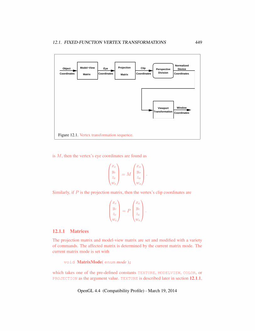
12.1. FIXED-FUNCTION VERTEX TRANSFORMATIONS 449
Object
Coordinates Coordinates
Eye
Coordinates
Window
Coordinates
NormalizedDeviceModel−View
Matrix
PerspectiveDivision
ViewportTransformation
Coordinates
ClipProjection
Matrix
Figure 12.1. Vertex transformation sequence.
is M , then the vertex’s eye coordinates are found asxeyezewe
= M
xoyozowo
.
Similarly, if P is the projection matrix, then the vertex’s clip coordinates arexcyczcwc
= P
xeyezewe
.
12.1.1 Matrices
The projection matrix and model-view matrix are set and modified with a varietyof commands. The affected matrix is determined by the current matrix mode. Thecurrent matrix mode is set with
void MatrixMode( enum mode );
which takes one of the pre-defined constants TEXTURE, MODELVIEW, COLOR, orPROJECTION as the argument value. TEXTURE is described later in section 12.1.1,
OpenGL 4.4 (Compatibility Profile) - March 19, 2014

12.1. FIXED-FUNCTION VERTEX TRANSFORMATIONS 450
and COLOR is described in section 8.4.3. If the current matrix mode is MODELVIEW,then matrix operations apply to the model-view matrix; if PROJECTION, then theyapply to the projection matrix.
The two basic commands for affecting the current matrix are
void LoadMatrix{fd}( const T m[16] );void MultMatrix{fd}( const T m[16] );
LoadMatrix takes a pointer to a 4× 4 matrix stored in column-major order as 16consecutive floating-point values, i.e. as
a1 a5 a9 a13a2 a6 a10 a14a3 a7 a11 a15a4 a8 a12 a16
.
(This differs from the standard row-major C ordering for matrix elements. If thestandard ordering is used, all of the subsequent transformation equations are trans-posed, and the columns representing vectors become rows.)
The specified matrix replaces the current matrix with the one pointed to. Mult-Matrix takes the same type argument as LoadMatrix, but multiplies the currentmatrix by the one pointed to and replaces the current matrix with the product. If Cis the current matrix and M is the matrix pointed to by MultMatrix’s argument,then the resulting current matrix, C ′, is
C ′ = C ·M.
The commands
void LoadTransposeMatrix{fd}( const T m[16] );void MultTransposeMatrix{fd}( const T m[16] );
take pointers to 4×4 matrices stored in row-major order as 16 consecutive floating-point values, i.e. as
a1 a2 a3 a4a5 a6 a7 a8a9 a10 a11 a12a13 a14 a15 a16
.
The effect of
LoadTransposeMatrix[fd](m);
OpenGL 4.4 (Compatibility Profile) - March 19, 2014
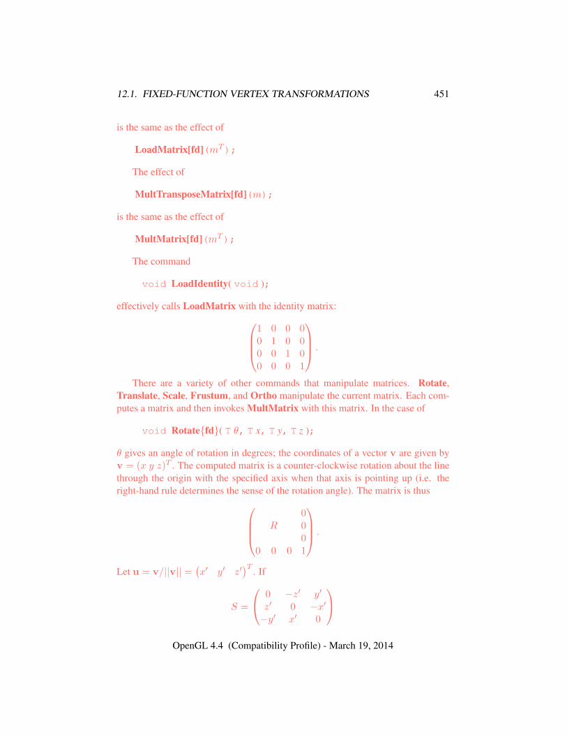
12.1. FIXED-FUNCTION VERTEX TRANSFORMATIONS 451
is the same as the effect of
LoadMatrix[fd](mT);
The effect of
MultTransposeMatrix[fd](m);
is the same as the effect of
MultMatrix[fd](mT);
The command
void LoadIdentity( void );
effectively calls LoadMatrix with the identity matrix:1 0 0 00 1 0 00 0 1 00 0 0 1
.
There are a variety of other commands that manipulate matrices. Rotate,Translate, Scale, Frustum, and Ortho manipulate the current matrix. Each com-putes a matrix and then invokes MultMatrix with this matrix. In the case of
void Rotate{fd}( T θ, T x, T y, T z );
θ gives an angle of rotation in degrees; the coordinates of a vector v are given byv = (x y z)T . The computed matrix is a counter-clockwise rotation about the linethrough the origin with the specified axis when that axis is pointing up (i.e. theright-hand rule determines the sense of the rotation angle). The matrix is thus
0R 0
00 0 0 1
.
Let u = v/||v|| =(x′ y′ z′
)T . If
S =
0 −z′ y′
z′ 0 −x′−y′ x′ 0
OpenGL 4.4 (Compatibility Profile) - March 19, 2014
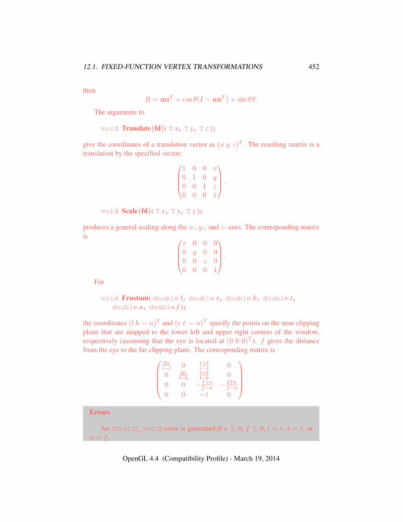
12.1. FIXED-FUNCTION VERTEX TRANSFORMATIONS 452
thenR = uuT + cos θ(I − uuT ) + sin θS.
The arguments to
void Translate{fd}( T x, T y, T z );
give the coordinates of a translation vector as (x y z)T . The resulting matrix is atranslation by the specified vector:
1 0 0 x0 1 0 y0 0 1 z0 0 0 1
.
void Scale{fd}( T x, T y, T z );
produces a general scaling along the x-, y-, and z- axes. The corresponding matrixis
x 0 0 00 y 0 00 0 z 00 0 0 1
.
For
void Frustum( double l, double r, double b, double t,double n, double f );
the coordinates (l b − n)T and (r t − n)T specify the points on the near clippingplane that are mapped to the lower left and upper right corners of the window,respectively (assuming that the eye is located at (0 0 0)T ). f gives the distancefrom the eye to the far clipping plane. The corresponding matrix is
2nr−l 0 r+l
r−l 0
0 2nt−b
t+bt−b 0
0 0 −f+nf−n − 2fn
f−n0 0 −1 0
.
Errors
An INVALID_VALUE error is generated if n ≤ 0, f ≤ 0, l = r, b = t, orn = f .
OpenGL 4.4 (Compatibility Profile) - March 19, 2014
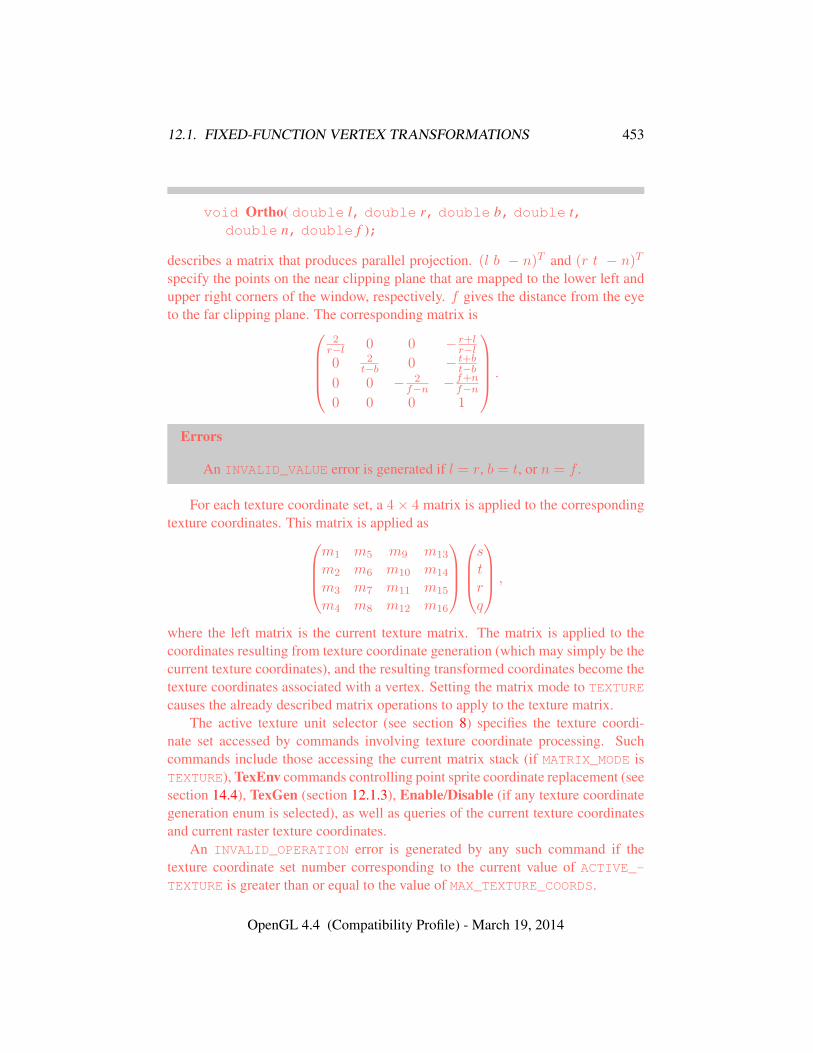
12.1. FIXED-FUNCTION VERTEX TRANSFORMATIONS 453
void Ortho( double l, double r, double b, double t,double n, double f );
describes a matrix that produces parallel projection. (l b − n)T and (r t − n)T
specify the points on the near clipping plane that are mapped to the lower left andupper right corners of the window, respectively. f gives the distance from the eyeto the far clipping plane. The corresponding matrix is
2r−l 0 0 − r+l
r−l0 2
t−b 0 − t+bt−b
0 0 − 2f−n −f+n
f−n0 0 0 1
.
Errors
An INVALID_VALUE error is generated if l = r, b = t, or n = f .
For each texture coordinate set, a 4× 4 matrix is applied to the correspondingtexture coordinates. This matrix is applied as
m1 m5 m9 m13
m2 m6 m10 m14
m3 m7 m11 m15
m4 m8 m12 m16
strq
,
where the left matrix is the current texture matrix. The matrix is applied to thecoordinates resulting from texture coordinate generation (which may simply be thecurrent texture coordinates), and the resulting transformed coordinates become thetexture coordinates associated with a vertex. Setting the matrix mode to TEXTURE
causes the already described matrix operations to apply to the texture matrix.The active texture unit selector (see section 8) specifies the texture coordi-
nate set accessed by commands involving texture coordinate processing. Suchcommands include those accessing the current matrix stack (if MATRIX_MODE isTEXTURE), TexEnv commands controlling point sprite coordinate replacement (seesection 14.4), TexGen (section 12.1.3), Enable/Disable (if any texture coordinategeneration enum is selected), as well as queries of the current texture coordinatesand current raster texture coordinates.
An INVALID_OPERATION error is generated by any such command if thetexture coordinate set number corresponding to the current value of ACTIVE_-TEXTURE is greater than or equal to the value of MAX_TEXTURE_COORDS.
OpenGL 4.4 (Compatibility Profile) - March 19, 2014
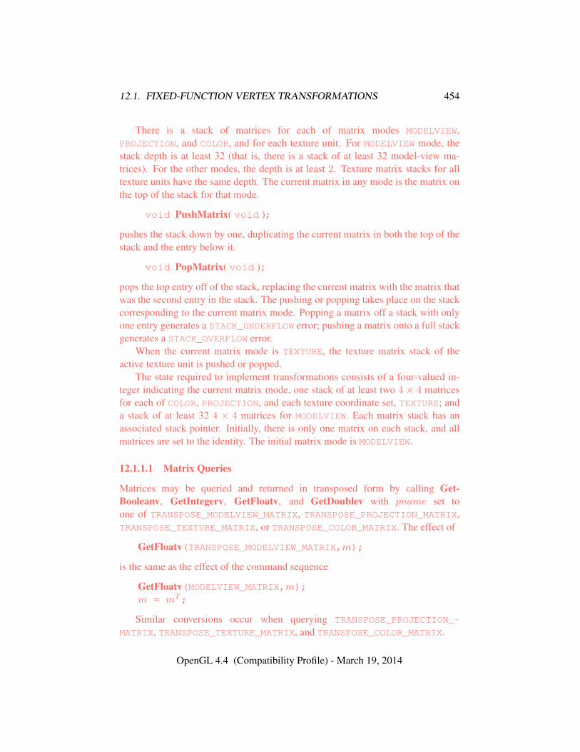
12.1. FIXED-FUNCTION VERTEX TRANSFORMATIONS 454
There is a stack of matrices for each of matrix modes MODELVIEW,PROJECTION, and COLOR, and for each texture unit. For MODELVIEW mode, thestack depth is at least 32 (that is, there is a stack of at least 32 model-view ma-trices). For the other modes, the depth is at least 2. Texture matrix stacks for alltexture units have the same depth. The current matrix in any mode is the matrix onthe top of the stack for that mode.
void PushMatrix( void );
pushes the stack down by one, duplicating the current matrix in both the top of thestack and the entry below it.
void PopMatrix( void );
pops the top entry off of the stack, replacing the current matrix with the matrix thatwas the second entry in the stack. The pushing or popping takes place on the stackcorresponding to the current matrix mode. Popping a matrix off a stack with onlyone entry generates a STACK_UNDERFLOW error; pushing a matrix onto a full stackgenerates a STACK_OVERFLOW error.
When the current matrix mode is TEXTURE, the texture matrix stack of theactive texture unit is pushed or popped.
The state required to implement transformations consists of a four-valued in-teger indicating the current matrix mode, one stack of at least two 4 × 4 matricesfor each of COLOR, PROJECTION, and each texture coordinate set, TEXTURE; anda stack of at least 32 4 × 4 matrices for MODELVIEW. Each matrix stack has anassociated stack pointer. Initially, there is only one matrix on each stack, and allmatrices are set to the identity. The initial matrix mode is MODELVIEW.
12.1.1.1 Matrix Queries
Matrices may be queried and returned in transposed form by calling Get-Booleanv, GetIntegerv, GetFloatv, and GetDoublev with pname set toone of TRANSPOSE_MODELVIEW_MATRIX, TRANSPOSE_PROJECTION_MATRIX,TRANSPOSE_TEXTURE_MATRIX, or TRANSPOSE_COLOR_MATRIX. The effect of
GetFloatv(TRANSPOSE_MODELVIEW_MATRIX,m);
is the same as the effect of the command sequence
GetFloatv(MODELVIEW_MATRIX,m);m = mT;
Similar conversions occur when querying TRANSPOSE_PROJECTION_-
MATRIX, TRANSPOSE_TEXTURE_MATRIX, and TRANSPOSE_COLOR_MATRIX.
OpenGL 4.4 (Compatibility Profile) - March 19, 2014

12.1. FIXED-FUNCTION VERTEX TRANSFORMATIONS 455
12.1.2 Normal Transformation
Finally, we consider how the model-view matrix and transformation state affectnormals. Before use in lighting, normals are transformed to eye coordinates by amatrix derived from the model-view matrix. Rescaling and normalization opera-tions are performed on the transformed normals to make them unit length prior touse in lighting. Rescaling and normalization are controlled by calling Enable andDisable with target RESCALE_NORMAL or NORMALIZE, respectively. This requirestwo bits of state. The initial state is for normals not to be rescaled or normalized.
If the model-view matrix is M , then the normal is transformed to eye coordi-nates by: (
nx′ ny
′ nz′ q′
)=(nx ny nz q
)·M−1
where, if
xyzw
are the associated vertex coordinates, then
q =
0, w = 0,
−(nx ny nz
)x
y
z
w , w 6= 0
(12.1)
Implementations may choose instead to transform(nx ny nz
)to eye coor-
dinates using (nx′ ny
′ nz′) =
(nx ny nz
)·Mu
−1
where Mu is the upper leftmost 3x3 matrix taken from M .Rescale multiplies the transformed normals by a scale factor(
nx′′ ny
′′ nz′′) = f
(nx′ ny
′ nz′)
If rescaling is disabled, then f = 1. If rescaling is enabled, then f is computedas (mij denotes the matrix element in row i and column j of M−1, numbering thetopmost row of the matrix as row 1 and the leftmost column as column 1)
f =1√
m312 +m32
2 +m332
Note that if the normals sent to GL were unit length and the model-view matrixuniformly scales space, then rescale makes the transformed normals unit length.
OpenGL 4.4 (Compatibility Profile) - March 19, 2014
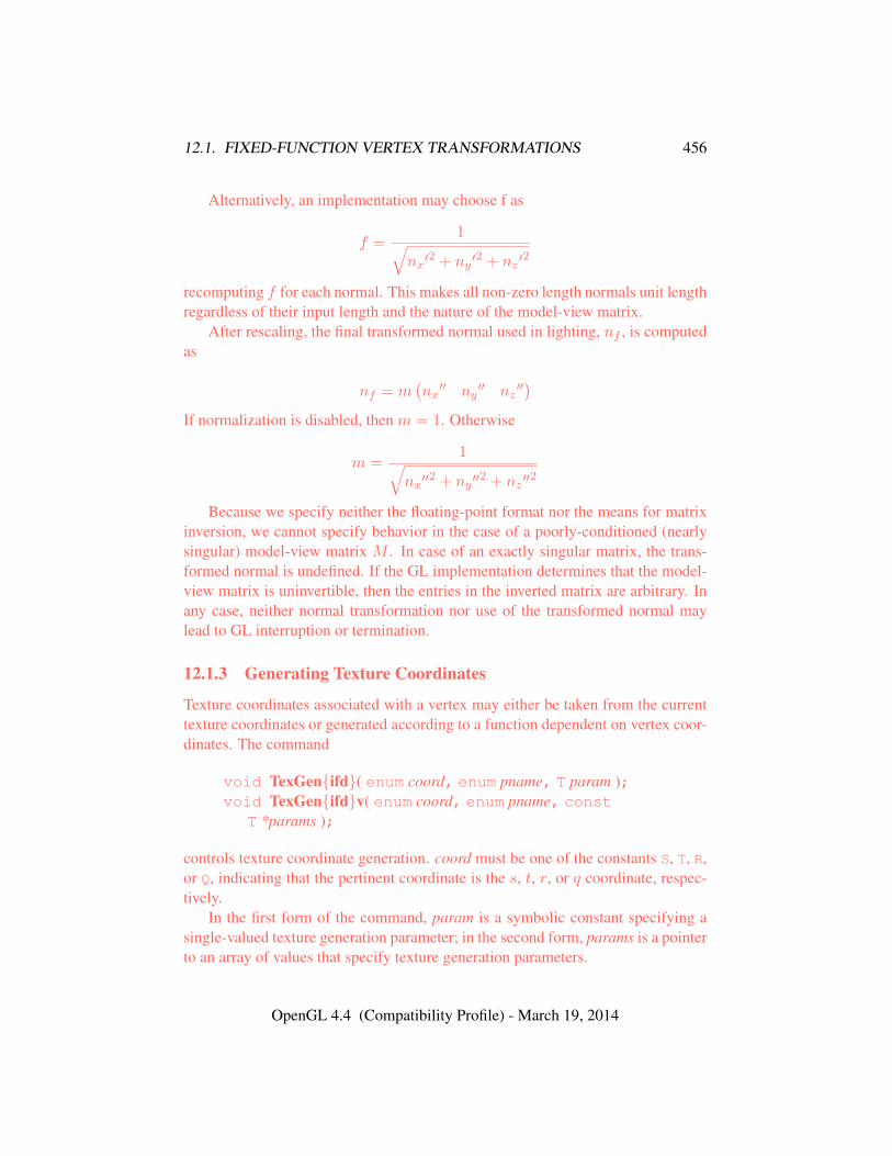
12.1. FIXED-FUNCTION VERTEX TRANSFORMATIONS 456
Alternatively, an implementation may choose f as
f =1√
nx′2 + ny ′
2 + nz ′2
recomputing f for each normal. This makes all non-zero length normals unit lengthregardless of their input length and the nature of the model-view matrix.
After rescaling, the final transformed normal used in lighting, nf , is computedas
nf = m(nx′′ ny
′′ nz′′)
If normalization is disabled, then m = 1. Otherwise
m =1√
nx′′2 + ny ′′
2 + nz ′′2
Because we specify neither the floating-point format nor the means for matrixinversion, we cannot specify behavior in the case of a poorly-conditioned (nearlysingular) model-view matrix M . In case of an exactly singular matrix, the trans-formed normal is undefined. If the GL implementation determines that the model-view matrix is uninvertible, then the entries in the inverted matrix are arbitrary. Inany case, neither normal transformation nor use of the transformed normal maylead to GL interruption or termination.
12.1.3 Generating Texture Coordinates
Texture coordinates associated with a vertex may either be taken from the currenttexture coordinates or generated according to a function dependent on vertex coor-dinates. The command
void TexGen{ifd}( enum coord, enum pname, T param );void TexGen{ifd}v( enum coord, enum pname, const
T *params );
controls texture coordinate generation. coord must be one of the constants S, T, R,or Q, indicating that the pertinent coordinate is the s, t, r, or q coordinate, respec-tively.
In the first form of the command, param is a symbolic constant specifying asingle-valued texture generation parameter; in the second form, params is a pointerto an array of values that specify texture generation parameters.
OpenGL 4.4 (Compatibility Profile) - March 19, 2014
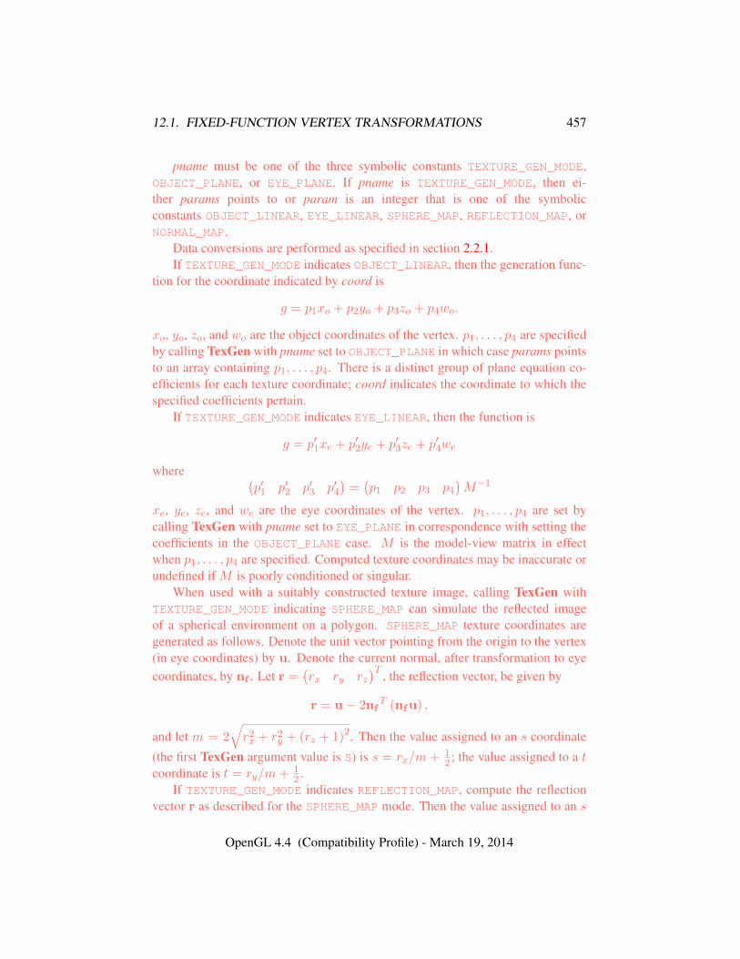
12.1. FIXED-FUNCTION VERTEX TRANSFORMATIONS 457
pname must be one of the three symbolic constants TEXTURE_GEN_MODE,OBJECT_PLANE, or EYE_PLANE. If pname is TEXTURE_GEN_MODE, then ei-ther params points to or param is an integer that is one of the symbolicconstants OBJECT_LINEAR, EYE_LINEAR, SPHERE_MAP, REFLECTION_MAP, orNORMAL_MAP.
Data conversions are performed as specified in section 2.2.1.If TEXTURE_GEN_MODE indicates OBJECT_LINEAR, then the generation func-
tion for the coordinate indicated by coord is
g = p1xo + p2yo + p3zo + p4wo.
xo, yo, zo, and wo are the object coordinates of the vertex. p1, . . . , p4 are specifiedby calling TexGen with pname set to OBJECT_PLANE in which case params pointsto an array containing p1, . . . , p4. There is a distinct group of plane equation co-efficients for each texture coordinate; coord indicates the coordinate to which thespecified coefficients pertain.
If TEXTURE_GEN_MODE indicates EYE_LINEAR, then the function is
g = p′1xe + p′2ye + p′3ze + p′4we
where (p′1 p′2 p′3 p′4
)=(p1 p2 p3 p4
)M−1
xe, ye, ze, and we are the eye coordinates of the vertex. p1, . . . , p4 are set bycalling TexGen with pname set to EYE_PLANE in correspondence with setting thecoefficients in the OBJECT_PLANE case. M is the model-view matrix in effectwhen p1, . . . , p4 are specified. Computed texture coordinates may be inaccurate orundefined if M is poorly conditioned or singular.
When used with a suitably constructed texture image, calling TexGen withTEXTURE_GEN_MODE indicating SPHERE_MAP can simulate the reflected imageof a spherical environment on a polygon. SPHERE_MAP texture coordinates aregenerated as follows. Denote the unit vector pointing from the origin to the vertex(in eye coordinates) by u. Denote the current normal, after transformation to eyecoordinates, by nf . Let r =
(rx ry rz
)T , the reflection vector, be given by
r = u− 2nfT (nfu) ,
and let m = 2√r2x + r2y + (rz + 1)2. Then the value assigned to an s coordinate
(the first TexGen argument value is S) is s = rx/m+ 12 ; the value assigned to a t
coordinate is t = ry/m+ 12 .
If TEXTURE_GEN_MODE indicates REFLECTION_MAP, compute the reflectionvector r as described for the SPHERE_MAP mode. Then the value assigned to an s
OpenGL 4.4 (Compatibility Profile) - March 19, 2014
12.1. FIXED-FUNCTION VERTEX TRANSFORMATIONS 458
coordinate is s = rx; the value assigned to a t coordinate is t = ry; and the valueassigned to an r coordinate is r = rz .
If TEXTURE_GEN_MODE indicates NORMAL_MAP, compute the normal vectornf as described in section 12.1.2. Then the value assigned to an s coordinate iss = nf x; the value assigned to a t coordinate is t = nf y; and the value assignedto an r coordinate is r = nf z (the values nf x, nf y, and nf z are the components ofnf .)
Errors
An INVALID_ENUM error is generated if coord is not S, T, R, or Q.An INVALID_ENUM error is generated if pname is not TEXTURE_GEN_-
MODE, OBJECT_PLANE, or EYE_PLANE.An INVALID_ENUM error is generated if coord is either R or Q, and pname
is SPHERE_MAP.An INVALID_ENUM error is generated if coord is Q and pname is
REFLECTION_MAP.An INVALID_ENUM error is generated if coord is Q and pname is
NORMAL_MAP.
A texture coordinate generation function is enabled or disabled by calling En-able and Disable with target TEXTURE_GEN_S, TEXTURE_GEN_T, TEXTURE_-GEN_R, or TEXTURE_GEN_Q (each indicates the corresponding texture coordinate).When enabled, the specified texture coordinate is computed according to the cur-rent EYE_LINEAR, OBJECT_LINEAR or SPHERE_MAP specification, depending onthe current setting of TEXTURE_GEN_MODE for that coordinate. When disabled,subsequent vertices will take the indicated texture coordinate from the current tex-ture coordinates.
The state required for texture coordinate generation for each texture unit com-prises a five-valued integer for each coordinate indicating coordinate generationmode, and a bit for each coordinate to indicate whether texture coordinate genera-tion is enabled or disabled. In addition, four coefficients are required for the fourcoordinates for each of EYE_LINEAR and OBJECT_LINEAR. The initial state hasthe texture generation function disabled for all texture coordinates. The initial val-ues of pi for s are all 0 except p1 which is one; for t all the pi are zero except p2,which is 1. The values of pi for r and q are all 0. These values of pi apply for boththe EYE_LINEAR and OBJECT_LINEAR versions. Initially all texture generationmodes are EYE_LINEAR.
OpenGL 4.4 (Compatibility Profile) - March 19, 2014
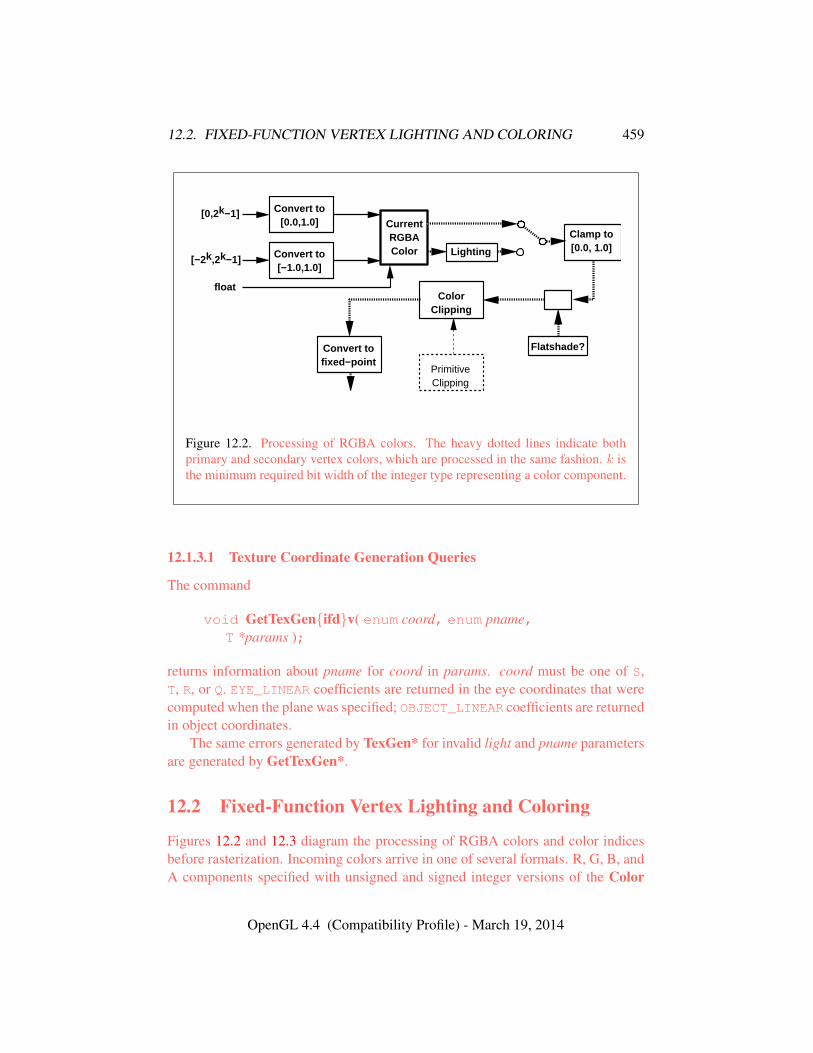
12.2. FIXED-FUNCTION VERTEX LIGHTING AND COLORING 459
[0,2k−1]
float
Convert to[0.0,1.0]
[−2k,2k−1] Convert to[−1.0,1.0]
CurrentRGBAColor Lighting
Clamp to[0.0, 1.0]
Flatshade?
PrimitiveClipping
ColorClipping
Convert tofixed−point
Figure 12.2. Processing of RGBA colors. The heavy dotted lines indicate bothprimary and secondary vertex colors, which are processed in the same fashion. k isthe minimum required bit width of the integer type representing a color component.
12.1.3.1 Texture Coordinate Generation Queries
The command
void GetTexGen{ifd}v( enum coord, enum pname,T *params );
returns information about pname for coord in params. coord must be one of S,T, R, or Q. EYE_LINEAR coefficients are returned in the eye coordinates that werecomputed when the plane was specified; OBJECT_LINEAR coefficients are returnedin object coordinates.
The same errors generated by TexGen* for invalid light and pname parametersare generated by GetTexGen*.
12.2 Fixed-Function Vertex Lighting and Coloring
Figures 12.2 and 12.3 diagram the processing of RGBA colors and color indicesbefore rasterization. Incoming colors arrive in one of several formats. R, G, B, andA components specified with unsigned and signed integer versions of the Color
OpenGL 4.4 (Compatibility Profile) - March 19, 2014
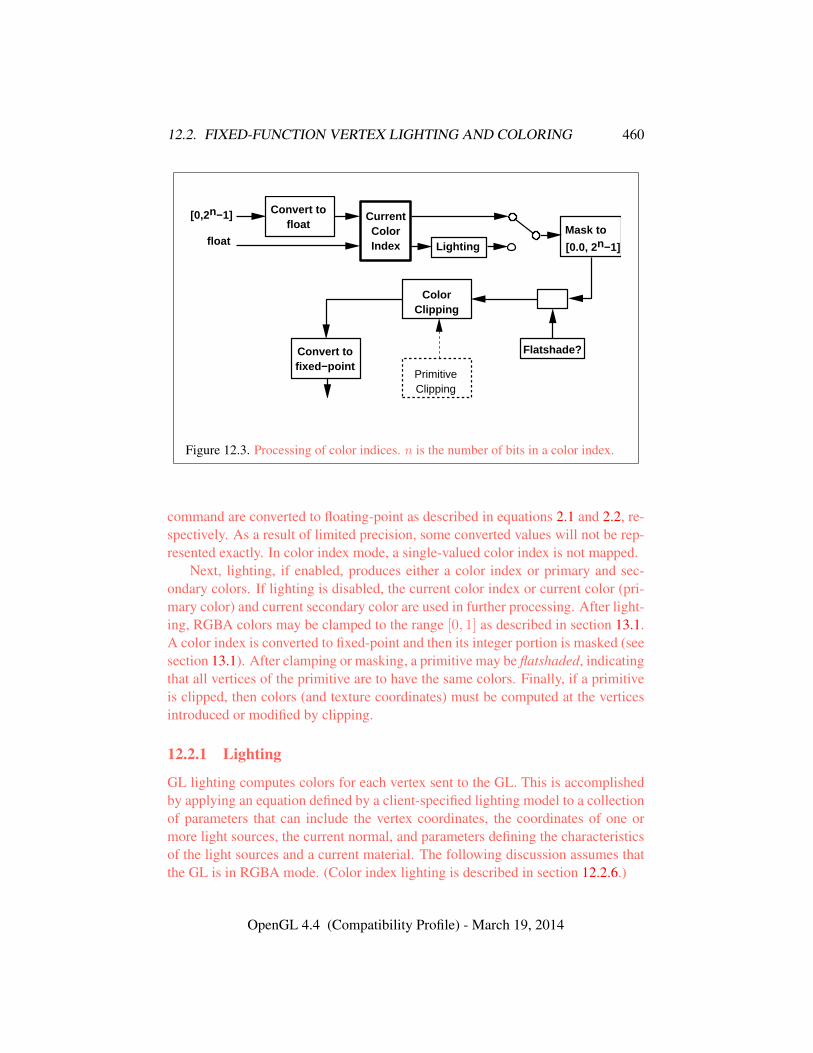
12.2. FIXED-FUNCTION VERTEX LIGHTING AND COLORING 460
Convert tofloat
[0,2n−1]
float
CurrentColorIndex Lighting
Mask to
[0.0, 2n−1]
Flatshade?
PrimitiveClipping
ColorClipping
Convert tofixed−point
Figure 12.3. Processing of color indices. n is the number of bits in a color index.
command are converted to floating-point as described in equations 2.1 and 2.2, re-spectively. As a result of limited precision, some converted values will not be rep-resented exactly. In color index mode, a single-valued color index is not mapped.
Next, lighting, if enabled, produces either a color index or primary and sec-ondary colors. If lighting is disabled, the current color index or current color (pri-mary color) and current secondary color are used in further processing. After light-ing, RGBA colors may be clamped to the range [0, 1] as described in section 13.1.A color index is converted to fixed-point and then its integer portion is masked (seesection 13.1). After clamping or masking, a primitive may be flatshaded, indicatingthat all vertices of the primitive are to have the same colors. Finally, if a primitiveis clipped, then colors (and texture coordinates) must be computed at the verticesintroduced or modified by clipping.
12.2.1 Lighting
GL lighting computes colors for each vertex sent to the GL. This is accomplishedby applying an equation defined by a client-specified lighting model to a collectionof parameters that can include the vertex coordinates, the coordinates of one ormore light sources, the current normal, and parameters defining the characteristicsof the light sources and a current material. The following discussion assumes thatthe GL is in RGBA mode. (Color index lighting is described in section 12.2.6.)
OpenGL 4.4 (Compatibility Profile) - March 19, 2014
12.2. FIXED-FUNCTION VERTEX LIGHTING AND COLORING 461
Lighting is turned on or off by calling Enable or Disable with targetLIGHTING. If lighting is off, the current color and current secondary color areassigned to the vertex primary and secondary color, respectively. If lighting is on,colors computed from the current lighting parameters are assigned to the vertexprimary and secondary colors.
12.2.1.1 Lighting Operation
A lighting parameter is of one of five types: color, position, direction, real, orboolean. A color parameter consists of four floating-point values, one for each ofR, G, B, and A, in that order. There are no restrictions on the allowable values forthese parameters. A position parameter consists of four floating-point coordinates(x, y, z, and w) that specify a position in object coordinates (w may be zero,indicating a point at infinity in the direction given by x, y, and z). A directionparameter consists of three floating-point coordinates (x, y, and z) that specify adirection in object coordinates. A real parameter is one floating-point value. Thevarious values and their types are summarized in table 12.1. The result of a lightingcomputation is undefined if a value for a parameter is specified that is outside therange given for that parameter in the table.
There are n light sources, indexed by i = 0, . . . , n−1. (n is an implementation-dependent maximum that must be at least 8.) Note that the default values for dcli
and scli differ for i = 0 and i > 0.Before specifying the way that lighting computes colors, we introduce oper-
ators and notation that simplify the expressions involved. If c1 and c2 are col-ors without alpha where c1 = (r1, g1, b1) and c2 = (r2, g2, b2), then definec1 ∗ c2 = (r1r2, g1g2, b1b2). Addition of colors is accomplished by addition ofthe components. Multiplication of colors by a scalar means multiplying each com-ponent by that scalar. If d1 and d2 are directions, then define
d1 � d2 = max{d1 · d2, 0}.
(Directions are taken to have three coordinates.) If P1 and P2 are (homogeneous,with four coordinates) points then let
−−−→P1P2 be the unit vector that points from P1
to P2. Note that if P2 has a zero w coordinate and P1 has non-zero w coordinate,then
−−−→P1P2 is the unit vector corresponding to the direction specified by the x, y,
and z coordinates of P2; if P1 has a zero w coordinate and P2 has a non-zero wcoordinate then
−−−→P1P2 is the unit vector that is the negative of that corresponding
to the direction specified by P1. If both P1 and P2 have zero w coordinates, then−−−→P1P2 is the unit vector obtained by normalizing the direction corresponding toP2 −P1.
OpenGL 4.4 (Compatibility Profile) - March 19, 2014
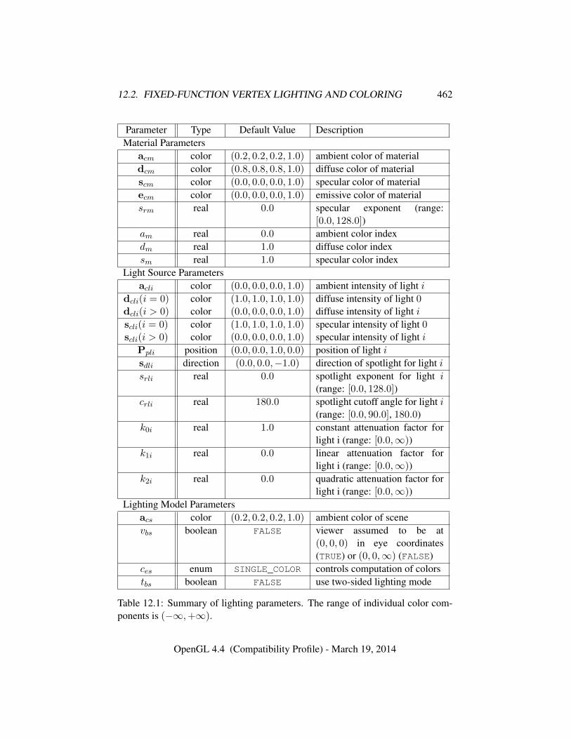
12.2. FIXED-FUNCTION VERTEX LIGHTING AND COLORING 462
Parameter Type Default Value DescriptionMaterial Parameters
acm color (0.2, 0.2, 0.2, 1.0) ambient color of materialdcm color (0.8, 0.8, 0.8, 1.0) diffuse color of materialscm color (0.0, 0.0, 0.0, 1.0) specular color of materialecm color (0.0, 0.0, 0.0, 1.0) emissive color of materialsrm real 0.0 specular exponent (range:
[0.0, 128.0])am real 0.0 ambient color indexdm real 1.0 diffuse color indexsm real 1.0 specular color index
Light Source Parametersacli color (0.0, 0.0, 0.0, 1.0) ambient intensity of light i
dcli(i = 0) color (1.0, 1.0, 1.0, 1.0) diffuse intensity of light 0dcli(i > 0) color (0.0, 0.0, 0.0, 1.0) diffuse intensity of light iscli(i = 0) color (1.0, 1.0, 1.0, 1.0) specular intensity of light 0scli(i > 0) color (0.0, 0.0, 0.0, 1.0) specular intensity of light i
Ppli position (0.0, 0.0, 1.0, 0.0) position of light isdli direction (0.0, 0.0,−1.0) direction of spotlight for light isrli real 0.0 spotlight exponent for light i
(range: [0.0, 128.0])crli real 180.0 spotlight cutoff angle for light i
(range: [0.0, 90.0], 180.0)k0i real 1.0 constant attenuation factor for
light i (range: [0.0,∞))k1i real 0.0 linear attenuation factor for
light i (range: [0.0,∞))k2i real 0.0 quadratic attenuation factor for
light i (range: [0.0,∞))Lighting Model Parameters
acs color (0.2, 0.2, 0.2, 1.0) ambient color of scenevbs boolean FALSE viewer assumed to be at
(0, 0, 0) in eye coordinates(TRUE) or (0, 0,∞) (FALSE)
ces enum SINGLE_COLOR controls computation of colorstbs boolean FALSE use two-sided lighting mode
Table 12.1: Summary of lighting parameters. The range of individual color com-ponents is (−∞,+∞).
OpenGL 4.4 (Compatibility Profile) - March 19, 2014
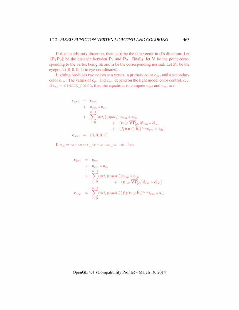
12.2. FIXED-FUNCTION VERTEX LIGHTING AND COLORING 463
If d is an arbitrary direction, then let d be the unit vector in d’s direction. Let‖P1P2‖ be the distance between P1 and P2. Finally, let V be the point corre-sponding to the vertex being lit, and n be the corresponding normal. Let Pe be theeyepoint ((0, 0, 0, 1) in eye coordinates).
Lighting produces two colors at a vertex: a primary color cpri and a secondarycolor csec. The values of cpri and csec depend on the light model color control, ces.If ces = SINGLE_COLOR, then the equations to compute cpri and csec are
cpri = ecm
+ acm ∗ acs
+
n−1∑i=0
(atti)(spoti) [acm ∗ acli+ (n�
−−→VPpli)dcm ∗ dcli
+ (fi)(n� hi)srmscm ∗ scli]
csec = (0, 0, 0, 1)
If ces = SEPARATE_SPECULAR_COLOR, then
cpri = ecm
+ acm ∗ acs
+n−1∑i=0
(atti)(spoti) [acm ∗ acli+ (n�
−−→VPpli)dcm ∗ dcli]
csec =n−1∑i=0
(atti)(spoti)(fi)(n� hi)srmscm ∗ scli
OpenGL 4.4 (Compatibility Profile) - March 19, 2014
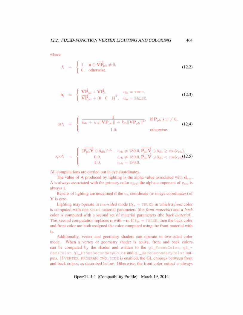
12.2. FIXED-FUNCTION VERTEX LIGHTING AND COLORING 464
where
fi =
{1, n�
−−→VPpli 6= 0,
0, otherwise,(12.2)
hi =
{ −−→VPpli +
−−→VPe, vbs = TRUE,
−−→VPpli +
(0 0 1
)T, vbs = FALSE,
(12.3)
atti =
1
k0i + k1i‖VPpli‖ + k2i‖VPpli‖2, if Ppli’s w 6= 0,
1.0, otherwise.(12.4)
spoti =
(−−−→PpliV � sdli)
srli , crli 6= 180.0,−−−→PpliV � sdli ≥ cos(crli),
0.0, crli 6= 180.0,−−−→PpliV � sdli < cos(crli),
1.0, crli = 180.0.
(12.5)
All computations are carried out in eye coordinates.The value of A produced by lighting is the alpha value associated with dcm.
A is always associated with the primary color cpri; the alpha component of csec isalways 1.
Results of lighting are undefined if the we coordinate (w in eye coordinates) ofV is zero.
Lighting may operate in two-sided mode (tbs = TRUE), in which a front coloris computed with one set of material parameters (the front material) and a backcolor is computed with a second set of material parameters (the back material).This second computation replaces n with −n. If tbs = FALSE, then the back colorand front color are both assigned the color computed using the front material withn.
Additionally, vertex and geometry shaders can operate in two-sided colormode. When a vertex or geometry shader is active, front and back colorscan be computed by the shader and written to the gl_FrontColor, gl_-
BackColor, gl_FrontSecondaryColor and gl_BackSecondaryColor out-puts. If VERTEX_PROGRAM_TWO_SIDE is enabled, the GL chooses between frontand back colors, as described below. Otherwise, the front color output is always
OpenGL 4.4 (Compatibility Profile) - March 19, 2014
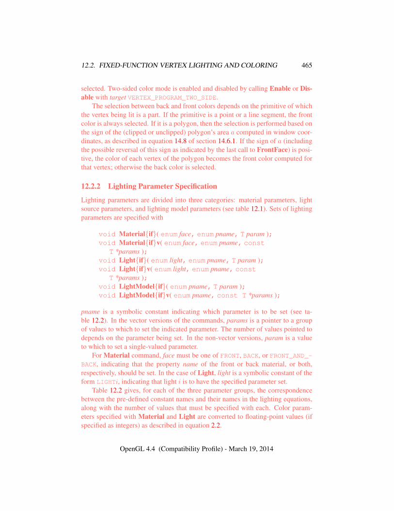
12.2. FIXED-FUNCTION VERTEX LIGHTING AND COLORING 465
selected. Two-sided color mode is enabled and disabled by calling Enable or Dis-able with target VERTEX_PROGRAM_TWO_SIDE.
The selection between back and front colors depends on the primitive of whichthe vertex being lit is a part. If the primitive is a point or a line segment, the frontcolor is always selected. If it is a polygon, then the selection is performed based onthe sign of the (clipped or unclipped) polygon’s area a computed in window coor-dinates, as described in equation 14.8 of section 14.6.1. If the sign of a (includingthe possible reversal of this sign as indicated by the last call to FrontFace) is posi-tive, the color of each vertex of the polygon becomes the front color computed forthat vertex; otherwise the back color is selected.
12.2.2 Lighting Parameter Specification
Lighting parameters are divided into three categories: material parameters, lightsource parameters, and lighting model parameters (see table 12.1). Sets of lightingparameters are specified with
void Material{if}( enum face, enum pname, T param );void Material{if}v( enum face, enum pname, const
T *params );void Light{if}( enum light, enum pname, T param );void Light{if}v( enum light, enum pname, const
T *params );void LightModel{if}( enum pname, T param );void LightModel{if}v( enum pname, const T *params );
pname is a symbolic constant indicating which parameter is to be set (see ta-ble 12.2). In the vector versions of the commands, params is a pointer to a groupof values to which to set the indicated parameter. The number of values pointed todepends on the parameter being set. In the non-vector versions, param is a valueto which to set a single-valued parameter.
For Material command, face must be one of FRONT, BACK, or FRONT_AND_-BACK, indicating that the property name of the front or back material, or both,respectively, should be set. In the case of Light, light is a symbolic constant of theform LIGHTi, indicating that light i is to have the specified parameter set.
Table 12.2 gives, for each of the three parameter groups, the correspondencebetween the pre-defined constant names and their names in the lighting equations,along with the number of values that must be specified with each. Color param-eters specified with Material and Light are converted to floating-point values (ifspecified as integers) as described in equation 2.2.
OpenGL 4.4 (Compatibility Profile) - March 19, 2014
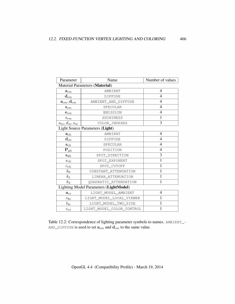
12.2. FIXED-FUNCTION VERTEX LIGHTING AND COLORING 466
Parameter Name Number of valuesMaterial Parameters (Material)
acm AMBIENT 4dcm DIFFUSE 4
acm,dcm AMBIENT_AND_DIFFUSE 4scm SPECULAR 4ecm EMISSION 4srm SHININESS 1
am, dm, sm COLOR_INDEXES 3Light Source Parameters (Light)
acli AMBIENT 4dcli DIFFUSE 4scli SPECULAR 4Ppli POSITION 4sdli SPOT_DIRECTION 3srli SPOT_EXPONENT 1crli SPOT_CUTOFF 1k0 CONSTANT_ATTENUATION 1k1 LINEAR_ATTENUATION 1k2 QUADRATIC_ATTENUATION 1
Lighting Model Parameters (LightModel)acs LIGHT_MODEL_AMBIENT 4vbs LIGHT_MODEL_LOCAL_VIEWER 1tbs LIGHT_MODEL_TWO_SIDE 1ces LIGHT_MODEL_COLOR_CONTROL 1
Table 12.2: Correspondence of lighting parameter symbols to names. AMBIENT_-AND_DIFFUSE is used to set acm and dcm to the same value.
OpenGL 4.4 (Compatibility Profile) - March 19, 2014
12.2. FIXED-FUNCTION VERTEX LIGHTING AND COLORING 467
Material properties can be changed inside a Begin / End pair by calling Ma-terial. However, when a vertex shader is active such property changes are notguaranteed to update material parameters, defined in table 12.2, until the followingEnd command.
The current model-view matrix is applied to the position parameter indicatedwith Light for a particular light source when that position is specified. Thesetransformed values are the values used in the lighting equation.
The spotlight direction is transformed when it is specified using only the upperleftmost 3x3 portion of the model-view matrix. That is, if Mu is the upper left 3x3matrix taken from the current model-view matrix M , then the spotlight directiondxdy
dz
is transformed to d′xd′y
d′z
= Mu
dxdydz
.
Errors
An INVALID_ENUM error is generated by Material* if face is not FRONT,BACK, or FRONT_AND_BACK.
An INVALID_ENUM error is generated by Light* if light is not one ofLIGHTi, where i is in the range zero to the value of MAX_LIGHTS minus oneand LIGHTi = LIGHT0 + i.
An INVALID_ENUM error is generated if pname is not an accepted param-eter name for the corresponding commands from table 12.2.
An INVALID_VALUE error is generated if a specified lighting parametervalue lies outside the allowable range for that parameter (see table 12.1; thesymbol “∞” indicates the maximum representable magnitude for the indicatedtype.)
An INVALID_ENUM error is generated by the scalar commands Mate-rial{if}, Light{if}, and LightModel{if} if param is a non-scalar parameter(e.g. if the number of values for that parameter, as shown in table 12.2, isgreater than 1).
An individual light is enabled or disabled by calling Enable or Disable withtarget LIGHTi, where i is in the range zero to the value of MAX_LIGHTS minus one.
OpenGL 4.4 (Compatibility Profile) - March 19, 2014
12.2. FIXED-FUNCTION VERTEX LIGHTING AND COLORING 468
If light i is disabled, the ith term in the lighting equation is effectively removedfrom the summation.
12.2.3 ColorMaterial
It is possible to attach one or more material properties to the current color, sothat they continuously track its component values. This behavior is enabled anddisabled by calling Enable or Disable with target COLOR_MATERIAL.
The command that controls which of these modes is selected is
void ColorMaterial( enum face, enum mode );
face is FRONT, BACK, or FRONT_AND_BACK, indicating whether the front ma-terial, back material, or both are affected by the current color.
mode is one of EMISSION, AMBIENT, DIFFUSE, SPECULAR, or AMBIENT_-AND_DIFFUSE and specifies which material property or properties track the currentcolor. If mode is EMISSION, AMBIENT, DIFFUSE, or SPECULAR, then the valueof ecm, acm, dcm or scm, respectively, will track the current color. If mode isAMBIENT_AND_DIFFUSE, both acm and dcm track the current color.
The replacements made to material properties are permanent; the replaced val-ues remain until changed by either sending a new color or by setting a new mate-rial value when ColorMaterial is not currently enabled to override that particularvalue. When COLOR_MATERIAL is enabled, the indicated parameter or parametersalways track the current color. For instance, calling
ColorMaterial(FRONT, AMBIENT)
while COLOR_MATERIAL is enabled sets the front material acm to the value of thecurrent color.
Material properties can be changed inside a Begin / End pair indirectly byenabling ColorMaterial mode and making Color calls. However, when a ver-tex shader is active such property changes are not guaranteed to update materialparameters, defined in table 12.2, until the following End command.
12.2.4 Lighting Parameter Queries
The command
void GetLight{if}v( enum light, enum pname, T *params );
OpenGL 4.4 (Compatibility Profile) - March 19, 2014
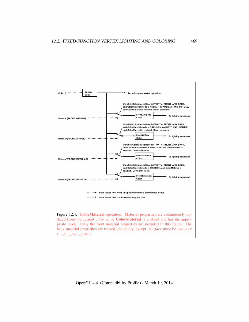
12.2. FIXED-FUNCTION VERTEX LIGHTING AND COLORING 469
CurrentColor
Front AmbientColor
Up while ColorMaterial face is FRONT or FRONT_AND_BACK,and ColorMaterial mode is AMBIENT or AMBIENT_AND_DIFFUSE,and ColorMaterial is enabled. Down otherwise.
Material*(FRONT,AMBIENT)To lighting equations
Front DiffuseColor
Up while ColorMaterial face is FRONT or FRONT_AND_BACK,and ColorMaterial mode is DIFFUSE or AMBIENT_AND_DIFFUSE,and ColorMaterial is enabled. Down otherwise.
Material*(FRONT,DIFFUSE)To lighting equations
Up while ColorMaterial face is FRONT or FRONT_AND_BACK,and ColorMaterial mode is SPECULAR, and ColorMaterial isenabled. Down otherwise.
Material*(FRONT,SPECULAR)To lighting equations
Front EmissionColor
Up while ColorMaterial face is FRONT or FRONT_AND_BACK,and ColorMaterial mode is EMISSION, and ColorMaterial isenabled. Down otherwise.
Material*(FRONT,EMISSION)To lighting equations
Front SpecularColor
Color*() To subsequent vertex operations
State values flow continuously along this path
State values flow along this path only when a command is issued
Figure 12.4. ColorMaterial operation. Material properties are continuously up-dated from the current color while ColorMaterial is enabled and has the appro-priate mode. Only the front material properties are included in this figure. Theback material properties are treated identically, except that face must be BACK orFRONT_AND_BACK.
OpenGL 4.4 (Compatibility Profile) - March 19, 2014
12.2. FIXED-FUNCTION VERTEX LIGHTING AND COLORING 470
returns information about light parameter pname for light in params. POSITIONand SPOT_DIRECTION return values in eye coordinates; these are the coordinatesthat were computed when the position or direction was specified.
The same errors generated by Light* for invalid light and pname parametersare generated by GetLight*.
The command
void GetMaterial{if}v( enum face, enum pname, T *params );
returns information about material property pname for face in params. face mustbe either FRONT or BACK, indicating the front or back material, respectively.
The same errors generated by Material* for invalid light and pname parame-ters are generated by GetMaterial*.
12.2.5 Lighting State
The state required for lighting consists of all of the lighting parameters (front andback material parameters, lighting model parameters, and at least 8 sets of light pa-rameters), a bit indicating whether a back color distinct from the front color shouldbe computed, at least 8 bits to indicate which lights are enabled, a five-valued vari-able indicating the current ColorMaterial mode, a bit indicating whether or notCOLOR_MATERIAL is enabled, and a single bit to indicate whether lighting is en-abled or disabled. In the initial state, all lighting parameters have their default val-ues. Back color evaluation does not take place, ColorMaterial is FRONT_AND_-BACK and AMBIENT_AND_DIFFUSE, and both lighting and COLOR_MATERIAL aredisabled.
12.2.6 Color Index Lighting
A simplified lighting computation applies in color index mode that uses many ofthe parameters controlling RGBA lighting, but none of the RGBA material param-eters. First, the RGBA diffuse and specular intensities of light i (dcli and scli,respectively) determine color index diffuse and specular light intensities, dli andsli from
dli = (.30)R(dcli) + (.59)G(dcli) + (.11)B(dcli)
andsli = (.30)R(scli) + (.59)G(scli) + (.11)B(scli).
R(x) indicates the R component of the color x and similarly for G(x) and B(x).
OpenGL 4.4 (Compatibility Profile) - March 19, 2014
12.2. FIXED-FUNCTION VERTEX LIGHTING AND COLORING 471
Next, let
s =n∑
i=0
(atti)(spoti)(sli)(fi)(n� hi)srm
where atti and spoti are given by equations 12.4 and 12.5, respectively, and fi andhi are given by equations 12.2 and 12.3, respectively. Let s′ = min{s, 1}. Finally,let
d =n∑
i=0
(atti)(spoti)(dli)(n�−−→VPpli).
Then color index lighting produces a value c, given by
c = am + d(1− s′)(dm − am) + s′(sm − am).
The final color index isc′ = min{c, sm}.
The values am, dm and sm are material properties described in tables 12.1 and 12.2.Any ambient light intensities are incorporated into am. As with RGBA lighting,disabled lights cause the corresponding terms from the summations to be omitted.The interpretation of tbs and the calculation of front and back colors is carried outas has already been described for RGBA lighting.
The values am, dm, and sm are set with Material using a pname of COLOR_-INDEXES. Their initial values are 0, 1, and 1, respectively. The additional stateconsists of three floating-point values. These values have no effect on RGBA light-ing.
OpenGL 4.4 (Compatibility Profile) - March 19, 2014
Chapter 13
Fixed-Function VertexPost-Processing
After programmable or fixed-function vertex processing, the following fixed-function operations are applied to vertices of the resulting primitives:
• Color clamping or masking (see section 13.1).
• Transform feedback (see section 13.2).
• Primitive queries (see section 13.3).
• Flatshading (see section 13.4).
• Primitive clipping, including client-defined clip planes (see section 13.5).
• Shader output or associated data clipping (see section 13.5.1).
• Perspective division on clip coordinates (see section 13.6).
• Viewport mapping, including depth range scaling (see section 13.6.1).
• Front face determination for polygon primitives (see section 14.6.1).
• Color, texture coordinate, fog, point-size and generic attribute clipping (seesection 13.5.1).
• Final color processing (see section 13.7).
Next, rasterization is performed on primitives as described in chapter 14).
472
13.1. CLAMPING OR MASKING 473
13.1 Clamping or Masking
When the GL is in RGBA mode and vertex color clamping is enabled, all com-ponents of both primary and secondary colors are clamped to the range [0, 1] af-ter lighting. If color clamping is disabled, the primary and secondary colors areunmodified. Vertex color clamping is controlled by calling ClampColor, as de-scribed in section 18.1.1, with a target of CLAMP_VERTEX_COLOR.
For a color index, the index is first converted to fixed-point with an unspecifiednumber of bits to the right of the binary point; the nearest fixed-point value isselected. Then, the bits to the right of the binary point are left alone while theinteger portion is masked (bitwise ANDed) with 2n − 1, where n is the number ofbits in a color in the color index buffer (buffers are discussed in chapter 9).
The state required for vertex color clamping is a three-valued integer, initiallyset to TRUE.
13.2 Transform Feedback
In transform feedback mode, attributes of the vertices of transformed primitivespassed to the transform feedback stage are written out to one or more buffer objects.The vertices are fed back after vertex color clamping, but before flatshading andclipping. The transformed vertices may be optionally discarded after being storedinto one or more buffer objects, or they can be passed on down to the clipping stagefor further processing. The set of attributes captured is determined when a programis linked.
The data captured in transform feedback mode depends on the active programson each of the shader stages. If a program is active for the geometry shader stage,transform feedback captures the vertices of each primitive emitted by the geometryshader. Otherwise, if a program is active for the tessellation evaluation shaderstage, transform feedback captures each primitive produced by the tessellationprimitive generator, whose vertices are processed by the tessellation evaluationshader. Otherwise, transform feedback captures each primitive processed by thevertex shader.
If separable program objects are in use, the set of attributes captured is takenfrom the program object active on the last shader stage processing the primitivescaptured by transform feedback. The set of attributes to capture in transform feed-back mode for any other program active on a previous shader stage is ignored.
OpenGL 4.4 (Compatibility Profile) - March 19, 2014
13.2. TRANSFORM FEEDBACK 474
13.2.1 Transform Feedback Objects
The set of buffer objects used to capture vertex output variables and related stateare stored in a transform feedback object. The set of attributes captured in trans-form feedback mode is determined using the state of the active program object.The name space for transform feedback objects is the unsigned integers. The namezero designates the default transform feedback object.
The command
void GenTransformFeedbacks( sizei n, uint *ids );
returns n previously unused transform feedback object names in ids. These namesare marked as used, for the purposes of GenTransformFeedbacks only, but theyacquire transform feedback state only when they are first bound.
Errors
An INVALID_VALUE error is generated if n is negative.
Transform feedback objects are deleted by calling
void DeleteTransformFeedbacks( sizei n, constuint *ids );
ids contains n names of transform feedback objects to be deleted. After a trans-form feedback object is deleted it has no contents, and its name is again unused.Unused names in ids that have been marked as used for the purposes of GenTrans-formFeedbacks are marked as unused again. Unused names in ids are silentlyignored, as is the value zero. The default transform feedback object cannot bedeleted.
Errors
An INVALID_VALUE error is generated if n is negative.An INVALID_OPERATION error is generated if the transform feedback
operation for any object named by ids is currently active.
The command
boolean IsTransformFeedback( uint id );
OpenGL 4.4 (Compatibility Profile) - March 19, 2014
13.2. TRANSFORM FEEDBACK 475
returns TRUE if id is the name of a transform feedback object. If id is zero, ora non-zero value that is not the name of a transform feedback object, IsTrans-formFeedback returns FALSE. No error is generated if id is not a valid transformfeedback object name.
A transform feedback object is created by binding a name returned by Gen-TransformFeedbacks with the command
void BindTransformFeedback( enum target, uint id );
target must be TRANSFORM_FEEDBACK and id is the transform feedback objectname. The resulting transform feedback object is a new state vector, comprisingall the state and with the same initial values listed in table 23.59. Additionally, thenew object is bound to the GL state vector and is used for subsequent transformfeedback operations.
BindTransformFeedback can also be used to bind an existing transform feed-back object to the GL state for subsequent use. If the bind is successful, no changeis made to the state of the newly bound transform feedback object and any previousbinding to target is broken.
While a transform feedback buffer is bound, GL operations on the target towhich it is bound affect the bound transform feedback object, and queries of thetarget to which a transform feedback object is bound return state from the boundobject. When buffer objects are bound for transform feedback, they are attached tothe currently bound transform feedback object. Buffer objects are used for trans-form feedback only if they are attached to the currently bound transform feedbackobject.
In the initial state, a default transform feedback object is bound and treated asa transform feedback object with a name of zero. That object is bound any timeBindTransformFeedback is called with id of zero.
Errors
An INVALID_ENUM error is generated if target is not TRANSFORM_-
FEEDBACK.An INVALID_OPERATION error is generated if the transform feedback
operation is active on the currently bound transform feedback object, and thatoperation is not paused (as described below).
An INVALID_OPERATION error is generated if id is not zero or a namereturned from a previous call to GenTransformFeedbacks, or if such a namehas since been deleted with DeleteTransformFeedbacks.
OpenGL 4.4 (Compatibility Profile) - March 19, 2014

13.2. TRANSFORM FEEDBACK 476
13.2.2 Transform Feedback Primitive Capture
Transform feedback for the currently bound transform feedback object is started(made active) and finished (made inactive) with the commands
void BeginTransformFeedback( enum primitiveMode );
and
void EndTransformFeedback( void );
respectively. primitiveMode must be TRIANGLES, LINES, or POINTS, and speci-fies the output type of primitives that will be recorded into the buffer objects boundfor transform feedback (see below). primitiveMode restricts the primitive typesthat may be rendered while transform feedback is active, as shown in table 13.1.
EndTransformFeedback first performs an implicit ResumeTransformFeed-back (see below) if transform feedback is paused.
BeginTransformFeedback and EndTransformFeedback calls must bepaired. Transform feedback is initially inactive.
Transform feedback mode captures the values of output variables written bythe vertex shader (or, if active, geometry shader). It may not be used during fixed-function vertex processing.
Errors
An INVALID_OPERATION error is generated by BeginTransformFeed-back if no vertex or geometry shader is active.
An INVALID_ENUM error is generated by BeginTransformFeedback ifprimitiveMode is not TRIANGLES, LINES, or POINTS.
An INVALID_OPERATION error is generated by BeginTransformFeed-back if transform feedback is active for the current transform feedback object.
An INVALID_OPERATION error is generated by EndTransformFeed-back if transform feedback is inactive.
Transform feedback operations for the currently bound transform feedback ob-ject may be paused and resumed by calling
void PauseTransformFeedback( void );
and
void ResumeTransformFeedback( void );
OpenGL 4.4 (Compatibility Profile) - March 19, 2014
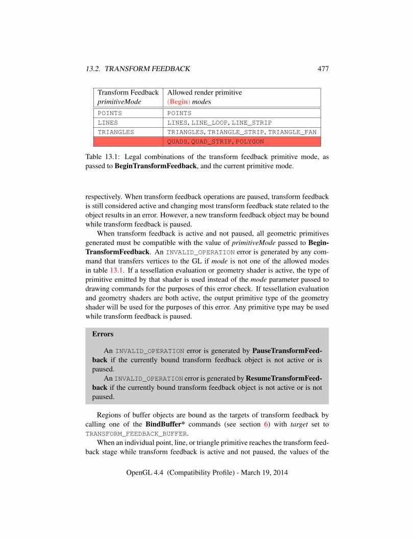
13.2. TRANSFORM FEEDBACK 477
Transform Feedback Allowed render primitiveprimitiveMode (Begin) modesPOINTS POINTS
LINES LINES, LINE_LOOP, LINE_STRIPTRIANGLES TRIANGLES, TRIANGLE_STRIP, TRIANGLE_FAN
QUADS, QUAD_STRIP, POLYGON
Table 13.1: Legal combinations of the transform feedback primitive mode, aspassed to BeginTransformFeedback, and the current primitive mode.
respectively. When transform feedback operations are paused, transform feedbackis still considered active and changing most transform feedback state related to theobject results in an error. However, a new transform feedback object may be boundwhile transform feedback is paused.
When transform feedback is active and not paused, all geometric primitivesgenerated must be compatible with the value of primitiveMode passed to Begin-TransformFeedback. An INVALID_OPERATION error is generated by any com-mand that transfers vertices to the GL if mode is not one of the allowed modesin table 13.1. If a tessellation evaluation or geometry shader is active, the type ofprimitive emitted by that shader is used instead of the mode parameter passed todrawing commands for the purposes of this error check. If tessellation evaluationand geometry shaders are both active, the output primitive type of the geometryshader will be used for the purposes of this error. Any primitive type may be usedwhile transform feedback is paused.
Errors
An INVALID_OPERATION error is generated by PauseTransformFeed-back if the currently bound transform feedback object is not active or ispaused.
An INVALID_OPERATION error is generated by ResumeTransformFeed-back if the currently bound transform feedback object is not active or is notpaused.
Regions of buffer objects are bound as the targets of transform feedback bycalling one of the BindBuffer* commands (see section 6) with target set toTRANSFORM_FEEDBACK_BUFFER.
When an individual point, line, or triangle primitive reaches the transform feed-back stage while transform feedback is active and not paused, the values of the
OpenGL 4.4 (Compatibility Profile) - March 19, 2014
13.2. TRANSFORM FEEDBACK 478
specified output variables of the vertex are appended to the buffer objects bound tothe transform feedback binding points. The attributes of the first vertex received af-ter BeginTransformFeedback are written at the starting offsets of the bound bufferobjects set by BindBufferRange, and subsequent vertex attributes are appended tothe buffer object. When capturing line and triangle primitives, all attributes of thefirst vertex are written first, followed by attributes of the subsequent vertices.
When capturing vertices, the stride associated with each transform feedbackbinding point indicates the number of basic machine units of storage reserved foreach vertex in the bound buffer object. For every vertex captured, each outputvariable with an assigned transform feedback offset will be written to the storagereserved for the vertex at the associated binding point. When writing output vari-ables that are arrays or structures, individual array elements or structure membersare written in order. For vector types, individual components are written in order.For matrix types, outputs are written as an array of column vectors. If any com-ponent of an output with an assigned transform feedback offset was not writtento by its shader, the value recorded for that component is undefined. The resultsof writing an output variable to a transform feedback buffer are undefined if anycomponent of that variable would be written at an offset not aligned to the size ofthe component. When capturing a vertex, any portion of the reserved storage notassociated with an output variable with an assigned transform feedback offset willbe unmodified.
When transform feedback is paused, no vertices are recorded. When transformfeedback is resumed, subsequent vertices are appended to the bound buffer ob-jects immediately following the last vertex written before transform feedback waspaused.
When quads and polygons are provided to transform feedback with a primitivemode of TRIANGLES, they will be tessellated and recorded as triangles (the order oftessellation within a primitive is undefined). Individual lines or triangles of a stripor fan primitive will be extracted and recorded separately. Incomplete primitivesare not recorded.
When using a geometry shader that writes vertices to multiple vertex streams,each vertex emitted may trigger a new primitive in the vertex stream to whichit was emitted. If transform feedback is active, the outputs of the primitive arewritten to a transform feedback binding point if and only if the outputs directed atthat binding point belong to the vertex stream in question. All outputs assigned toa given binding point are required to come from a single vertex stream.
If recording the vertices of a primitive to the buffer objects being used for trans-form feedback purposes would result in either exceeding the limits of any bufferobject’s size, or in exceeding the end position offset + size − 1, as set by Bind-BufferRange, then no vertices of that primitive are recorded in any buffer object,
OpenGL 4.4 (Compatibility Profile) - March 19, 2014
13.2. TRANSFORM FEEDBACK 479
and the counter corresponding to the asynchronous query target TRANSFORM_-FEEDBACK_PRIMITIVES_WRITTEN (see section 13.3) is not incremented. Forthe purposes of this test, gl_SkipComponents variables are counted as recordingdata to a buffer object.
Any transform feedback binding point used for capturing vertices must havebuffer objects bound when BeginTransformFeedback is called. A binding pointrequires a bound buffer object if and only if its associated stride in the programobject used for transform feedback primitive capture is non-zero.
An INVALID_OPERATION error is generated by BeginTransformFeedback ifany of these binding points does not have a buffer object bound.
An INVALID_OPERATION error is generated by BeginTransformFeedback ifno binding points would be used, either because no program object is active orbecause the active program object has specified no output variables to record.
When BeginTransformFeedback is called with an active program object con-taining a vertex or geometry shader, the set of output variables captured duringtransform feedback is taken from the active program object and may not be changedwhile transform feedback is active. That program object must be active until theEndTransformFeedback is called, except while the transform feedback object ispaused.
Errors
An INVALID_OPERATION error is generated :• by UseProgram if the current transform feedback object is active and
not paused;
• by UseProgramStages if the program pipeline object it refers to is cur-rent and the current transform feedback object is active and not paused;
• by BindProgramPipeline if the current transform feedback object isactive and not paused;
• by LinkProgram or ProgramBinary if program is the name of a pro-gram being used by one or more transform feedback objects, even if theobjects are not currently bound or are paused;
• by ResumeTransformFeedback if the program object being used bythe current transform feedback object is not active, or has been re-linkedsince transform feedback became active for the current transform feed-back object.
OpenGL 4.4 (Compatibility Profile) - March 19, 2014
13.2. TRANSFORM FEEDBACK 480
• by ResumeTransformFeedback if the program pipeline object beingused by the current transform feedback object is not bound, if any ofits shader stage bindings has changed, or if a single program object isactive and overriding it; and
• by BindBufferRange or BindBufferBase if target is TRANSFORM_-
FEEDBACK_BUFFER and transform feedback is currently active.
Buffers should not be bound or in use for both transform feedback and otherpurposes in the GL. Specifically, if a buffer object is simultaneously bound to atransform feedback buffer binding point and elsewhere in the GL, any writes toor reads from the buffer generate undefined values. Examples of such bindingsinclude DrawPixels and ReadPixels to a pixel buffer object binding point andclient access to a buffer mapped with MapBuffer. Commands that attempt to reador write to an active and unpaused transform feedback buffer will have undefinedresults. Generating an INVALID_OPERATION error is recommended in this case.
However, if a buffer object is written and read sequentially by transform feed-back and other mechanisms, it is the responsibility of the GL to ensure that dataare accessed consistently, even if the implementation performs the operations in apipelined manner. For example, MapBuffer may need to block pending the com-pletion of a previous transform feedback operation.
13.2.3 Transform Feedback Draw Operations
When transform feedback is active, the values of output variables or transformedvertex attributes are captured into the buffer objects attached to the current trans-form feedback object. After transform feedback is complete, subsequent renderingoperations may use the contents of these buffer objects (see section 6). The numberof vertices captured from each vertex stream during transform feedback is stored inthe corresponding transform feedback object and may be used in conjunction withthe commands
void DrawTransformFeedback( enum mode, uint id );void DrawTransformFeedbackInstanced( enum mode,
uint id, sizei instancecount );void DrawTransformFeedbackStream( enum mode, uint id,
uint stream );void DrawTransformFeedbackStreamInstanced( enum mode,
uint id, uint stream, sizei instancecount );
to replay the captured vertices.
OpenGL 4.4 (Compatibility Profile) - March 19, 2014
13.3. PRIMITIVE QUERIES 481
DrawTransformFeedbackStreamInstanced is equivalent to call-ing DrawArraysInstanced with mode as specified, first set to zero, count set tothe number of vertices captured from the vertex stream numbered stream the lasttime transform feedback was active on the transform feedback object named id,and instancecount as specified.
Calling DrawTransformFeedbackInstanced is equivalent to calling Draw-TransformFeedbackStreamInstanced with stream set to zero.
Calling DrawTransformFeedbackStream is equivalent to calling Draw-TransformFeedbackStreamInstanced with instancecount set to one.
Finally, calling DrawTransformFeedback is equivalent to calling Draw-TransformFeedbackStreamInstanced with stream set to zero and instancecountset to one.
Note that the vertex count is from the number of vertices recorded to the se-lected vertex stream during the transform feedback operation. If no outputs be-longing to the selected vertex stream are recorded, the corresponding vertex countwill be zero even if complete primitives were emitted to the selected stream.
No error is generated if the transform feedback object named by id is active;the vertex count used for the rendering operation is set by the previous EndTrans-formFeedback command.
Errors
An INVALID_VALUE error is generated if stream is greater than or equalto the value of MAX_VERTEX_STREAMS.
An INVALID_VALUE error is generated if id is not the name of a transformfeedback object.
An INVALID_VALUE error is generated if instancecount is negative.An INVALID_OPERATION error is generated if EndTransformFeedback
has never been called while the object named by id was bound.
13.3 Primitive Queries
Primitive queries use query objects to track the number of primitives in each vertexstream that are generated by the GL and the number of primitives in each vertexstream that are written to buffer objects in transform feedback mode.
When BeginQueryIndexed is called with a target of PRIMITIVES_-
GENERATED, the primitives generated count maintained by the GL for the vertexstream index is set to zero. There is a separate query and counter for each vertexstream. The number of vertex streams is given by the value of the implementation-
OpenGL 4.4 (Compatibility Profile) - March 19, 2014
13.4. FLATSHADING 482
dependent constant MAX_VERTEX_STREAMS. When a generated primitive queryfor a vertex stream is active, the primitives-generated count is incremented everytime a primitive emitted to that stream reaches the transform feedback stage (seesection 13.2), whether or not transform feedback is active. This counter countsthe number of primitives emitted by a geometry shader, if active, possibly furthertessellated into separate primitives during the transform feedback stage, if active.
When BeginQueryIndexed is called with a target of TRANSFORM_-
FEEDBACK_PRIMITIVES_WRITTEN, the transform feedback primitives writtencount maintained by the GL for vertex stream index is set to zero. There is aseparate query and counter for each vertex stream. When a transform feedbackprimitives written query for a vertex stream is active, the counter for that vertexstream is incremented every time the vertices of a primitive written to that streamare recorded into one or more buffer objects. If transform feedback is not activeor if a primitive to be recorded does not fit in a buffer object, the counter is notincremented.
These two types of queries can be used together to determine if all primitivesin a given vertex stream have been written to the bound feedback buffers; if bothqueries are run simultaneously and the query results are equal, all primitives havebeen written to the buffer(s). If the number of primitives written is less than thenumber of primitives generated, one or more buffers overflowed.
13.4 Flatshading
Flatshading a vertex shader output means to assign all vertices of the primitive thesame value for that output.
For fixed-function vertex processing, flatshading a primitive means to assign allvertices of the primitive the same primary and secondary colors (in RGBA mode)or the same color index (in color index mode).
The color and/or output values assigned are those of the provoking vertex ofthe primitive. The provoking vertex is controlled with the command
void ProvokingVertex( enum provokeMode );
provokeMode must be either FIRST_VERTEX_CONVENTION or LAST_VERTEX_-CONVENTION, and controls selection of the vertex whose values are assigned toflatshaded colors and outputs, as shown in table 13.2
The provoking vertex behavior of quad primitives is implementation depen-dent, and may be determined by calling GetBooleanv with the symbolic constantQUADS_FOLLOW_PROVOKING_VERTEX_CONVENTION. A return value of TRUE in-dicates that the provoking vertex mode is respected for quad primitives, while a
OpenGL 4.4 (Compatibility Profile) - March 19, 2014
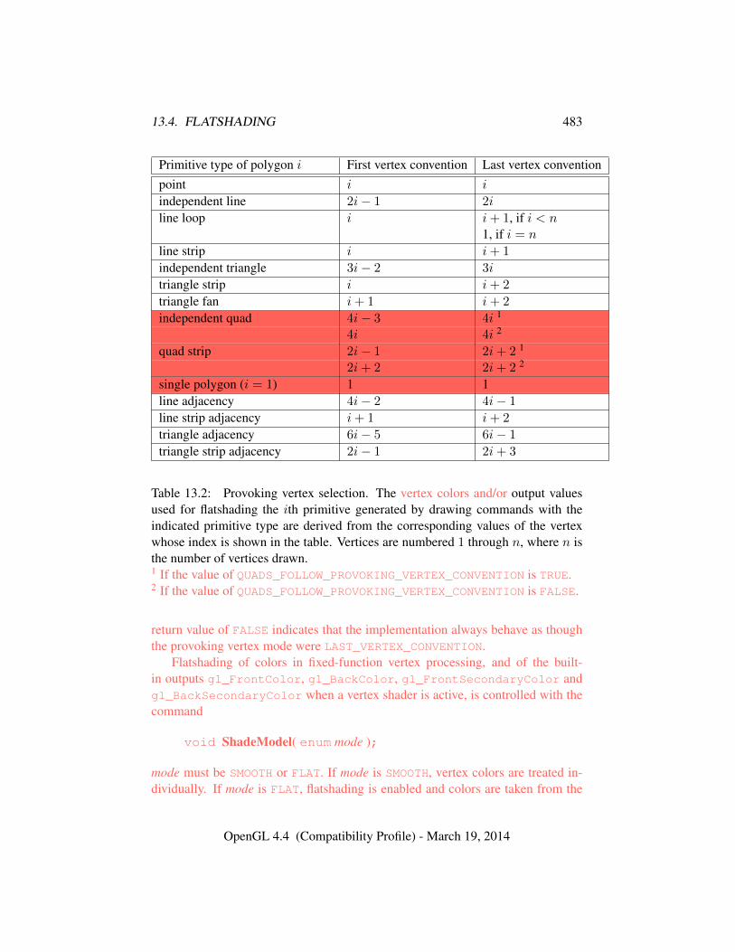
13.4. FLATSHADING 483
Primitive type of polygon i First vertex convention Last vertex conventionpoint i i
independent line 2i− 1 2i
line loop i i+ 1, if i < n1, if i = n
line strip i i+ 1
independent triangle 3i− 2 3i
triangle strip i i+ 2
triangle fan i+ 1 i+ 2
independent quad 4i− 3 4i 1
4i 4i 2
quad strip 2i− 1 2i+ 2 1
2i+ 2 2i+ 2 2
single polygon (i = 1) 1 1line adjacency 4i− 2 4i− 1
line strip adjacency i+ 1 i+ 2
triangle adjacency 6i− 5 6i− 1
triangle strip adjacency 2i− 1 2i+ 3
Table 13.2: Provoking vertex selection. The vertex colors and/or output valuesused for flatshading the ith primitive generated by drawing commands with theindicated primitive type are derived from the corresponding values of the vertexwhose index is shown in the table. Vertices are numbered 1 through n, where n isthe number of vertices drawn.1 If the value of QUADS_FOLLOW_PROVOKING_VERTEX_CONVENTION is TRUE.2 If the value of QUADS_FOLLOW_PROVOKING_VERTEX_CONVENTION is FALSE.
return value of FALSE indicates that the implementation always behave as thoughthe provoking vertex mode were LAST_VERTEX_CONVENTION.
Flatshading of colors in fixed-function vertex processing, and of the built-in outputs gl_FrontColor, gl_BackColor, gl_FrontSecondaryColor andgl_BackSecondaryColor when a vertex shader is active, is controlled with thecommand
void ShadeModel( enum mode );
mode must be SMOOTH or FLAT. If mode is SMOOTH, vertex colors are treated in-dividually. If mode is FLAT, flatshading is enabled and colors are taken from the
OpenGL 4.4 (Compatibility Profile) - March 19, 2014
13.5. PRIMITIVE CLIPPING 484
provoking vertex of the primitive. The colors selected are those derived from cur-rent values, generated by lighting, or generated by vertex shading, if lighting isdisabled, enabled, or a vertex shader is in use, respectively.
If a vertex or geometry shader is active, user-defined output variables may beflatshaded by using the flat qualifier when declaring the output, as described insection 4.5(“Interpolation Qualifiers”) of the OpenGL Shading Language Specifi-cation.
The state required for flatshading is one bit for the shade mode, one bit for theprovoking vertex mode, and one implementation-dependent bit for the provokingvertex behavior of quad primitives. The initial value of the shade mode is SMOOTHand the initial value of the provoking vertex mode is LAST_VERTEX_CONVENTION.
13.5 Primitive Clipping
Primitives are clipped to the clip volume. In clip coordinates, the view volume isdefined by
−wc ≤ xc ≤ wc
−wc ≤ yc ≤ wc
−wc ≤ zc ≤ wc.
This view volume may be further restricted by as many as n client-defined clipplanes to generate the clip volume. Each client-defined plane specifies a half-space.n is an implementation-dependent maximum that must be at least 8, and may
be determined by calling GetIntegerv with the symbolic constant MAX_CLIP_-DISTANCES. The clip volume is the intersection of all such half-spaces with theview volume (if no client-defined clip planes are enabled, the clip volume is theview volume).
A client-defined clip plane is specified with
void ClipPlane( enum p, const double eqn[4] );
The value of the first argument, p, is a symbolic constant, CLIP_PLANEi, where i isan integer between 0 and n− 1, indicating one of n client-defined clip planes. eqnis an array of four double-precision floating-point values. These are the coefficientsof a plane equation in object coordinates: p1, p2, p3, and p4 (in that order). Theinverse of the current model-view matrix is applied to these coefficients, at the timethey are specified, yielding(
p′1 p′2 p′3 p′4)
=(p1 p2 p3 p4
)M−1
(where M is the current model-view matrix; the resulting plane equation is unde-fined if M is singular and may be inaccurate if M is poorly-conditioned) to obtain
OpenGL 4.4 (Compatibility Profile) - March 19, 2014
13.5. PRIMITIVE CLIPPING 485
the plane equation coefficients in eye coordinates. All points with eye coordinates(xe ye ze we
)T that satisfy
(p′1 p′2 p′3 p′4
)xeyezewe
≥ 0
lie in the half-space defined by the plane; points that do not satisfy this conditiondo not lie in the half-space.
When a vertex shader is active, the vector(xe ye ze we
)T is no longercomputed. Instead, the value of the gl_ClipVertex built-in variable is used inits place. If gl_ClipVertex is not written by the vertex shader, its value is un-defined, which implies that the results of clipping to any client-defined clip planesare also undefined. The user must ensure that the clip vertex and client-defined clipplanes are defined in the same coordinate space.
A vertex shader may, instead of writing to gl_ClipVertex write a single clipdistance for each supported clip plane to elements of the gl_ClipDistance[]
array. The half-space corresponding to clip plane i is then given by the set ofpoints satisfying the inequality
ci(P ) ≥ 0,
where ci(P ) is the value of clip distance i at point P . For point primitives,ci(P ) is simply the clip distance for the vertex in question. For line and triangleprimitives, per-vertex clip distances are interpolated using a weighted mean, withweights derived according to the algorithms described in sections 14.5 and 14.6.
Client-defined clip planes are enabled or disabled by calling Enable or Disablewith target CLIP_DISTANCEi, where i is an integer between 0 and n−1; specify-ing a value of i enables or disables the plane equation with index i. The constantsobey CLIP_DISTANCEi = CLIP_DISTANCE0 + i.
Depth clamping is enabled or disabled by calling Enable or Disable with targetDEPTH_CLAMP. If depth clamping is enabled, the
−wc ≤ zc ≤ wc
plane equation is ignored by view volume clipping (effectively, there is no near orfar plane clipping).
If the primitive under consideration is a point, then clipping passes it un-changed if it lies within the clip volume; otherwise, it is discarded.
If the primitive is a line segment, then clipping does nothing to it if it liesentirely within the clip volume, and discards it if it lies entirely outside the volume.
OpenGL 4.4 (Compatibility Profile) - March 19, 2014
13.5. PRIMITIVE CLIPPING 486
If part of the line segment lies in the volume and part lies outside, then theline segment is clipped and new vertex coordinates are computed for one or bothvertices. A clipped line segment endpoint lies on both the original line segmentand the boundary of the clip volume.
This clipping produces a value, 0 ≤ t ≤ 1, for each clipped vertex. If thecoordinates of a clipped vertex are P and the original vertices’ coordinates are P1
and P2, then t is given by
P = tP1 + (1− t)P2.
The value of t is used to clip color, secondary color, texture coordinate, fog coor-dinate, and vertex shader outputs as described in section 13.5.1.
If the primitive is a polygon, then it is passed if every one of its edges liesentirely inside the clip volume and either clipped or discarded otherwise. Polygonclipping may cause polygon edges to be clipped, but because polygon connectivitymust be maintained, these clipped edges are connected by new edges that lie alongthe clip volume’s boundary. Thus, clipping may require the introduction of newvertices into a polygon. Edge flags are associated with these vertices so that edgesintroduced by clipping are flagged as boundary (edge flag TRUE), and so that orig-inal edges of the polygon that become cut off at these vertices retain their originalflags.
If it happens that a polygon intersects an edge of the clip volume’s boundary,then the clipped polygon must include a point on this boundary edge. This pointmust lie in the intersection of the boundary edge and the convex hull of the verticesof the original polygon. We impose this requirement because the polygon may notbe exactly planar.
Primitives rendered with user-defined clip planes must satisfy a complementar-ity criterion. Suppose a single clip plane with coefficients
(p′1 p′2 p′3 p′4
)(or a
number of similarly specified clip planes) is enabled and a series of primitives aredrawn. Next, suppose that the original clip plane is respecified with coefficients(−p′1 −p′2 −p′3 −p′4
)(and correspondingly for any other clip planes) and the
primitives are drawn again (and the GL is otherwise in the same state). In thiscase, primitives must not be missing any pixels, nor may any pixels be drawn twicein regions where those primitives are cut by the clip planes.
The state required for clipping is at least 8 bits indicating which of the client-defined plane equations are enabled, and at least 8 corresponding sets of planeequations (each consisting of four double-precision floating-point coefficients) Inthe initial state, all plane equations are disabled and all client-defined plane equa-tion coefficients are zero.
OpenGL 4.4 (Compatibility Profile) - March 19, 2014
13.5. PRIMITIVE CLIPPING 487
13.5.1 Color and Associated Data Clipping
After lighting, clamping or masking and possible flatshading, colors are clipped.Those colors associated with a vertex that lies within the clip volume are unaf-fected by clipping. If a primitive is clipped, however, the colors assigned to verticesproduced by clipping are clipped.
Let the colors assigned to the two vertices P1 and P2 of an unclipped edge bec1 and c2. The value of t (section 13.5) for a clipped point P is used to obtain thecolor associated with P as
c = tc1 + (1− t)c2.
(For a color index color, multiplying a color by a scalar means multiplying theindex by the scalar. For an RGBA color, it means multiplying each of R, G, B,and A by the scalar. Both primary and secondary colors are treated in the samefashion.)
Polygon clipping may create a clipped vertex along an edge of the clip volume’sboundary. This situation is handled by noting that polygon clipping proceeds byclipping against one plane of the clip volume’s boundary at a time. Color clippingis done in the same way, so that clipped points always occur at the intersection ofpolygon edges (possibly already clipped) with the clip volume’s boundary.
Texture and fog coordinates, vertex shader outputs (section 11.1.2.1), and pointsizes computed on a per vertex basis must also be clipped when a primitive isclipped. The method is exactly analogous to that used for color clipping.
For vertex shader outputs specified to be interpolated without perspective cor-rection (using the noperspective qualifier), the value of t used to obtain theoutput value associated with P will be adjusted to produce results that vary lin-early in screen space.
Outputs of integer or unsigned integer type must always be declared with theflat qualifier. Since such outputs are constant over the primitive being rasterized(see sections 14.5.1 and 14.6.1), no interpolation is performed.
13.5.2 Clip Plane Queries
The command
void GetClipPlane( enum plane, double eqn[4] );
returns four double-precision values in eqn; these are the coefficients of the planeequation of plane in eye coordinates (these coordinates are those that were com-puted when the plane was specified).
OpenGL 4.4 (Compatibility Profile) - March 19, 2014
13.6. COORDINATE TRANSFORMATIONS 488
Errors
An INVALID_ENUM error is generated if plane is not one of CLIP_-
DISTANCEi, where i is an integer between 0 and n− 1.
13.6 Coordinate Transformations
Clip coordinates for a vertex result from fixed-function transformation of the ver-tex coordinates, or from shader execution, which yields a vertex coordinate gl_-Position.
Perspective division on clip coordinates yields normalized device coordinates,followed by a viewport transformation (see section 13.6.1) to convert these coordi-nates into window coordinates.
If a vertex in clip coordinates is given by
xcyczcwc
then the vertex’s normalized device coordinates arexdyd
zd
=
xcwcycwczcwc
.
13.6.1 Controlling the Viewport
The viewport transformation is determined by the selected viewport’s width andheight in pixels, px and py, respectively, and its center (ox, oy) (also in pixels).
The vertex’s window coordinates,
xwywzw
, are given by
xwywzw
=
px2 xd + oxpy2 yd + oy
f−n2 zd + n+f
2
.
Multiple viewports are available and are numbered zero through the value ofMAX_VIEWPORTS minus one. If a geometry shader is active and writes to gl_-
ViewportIndex, the viewport transformation uses the viewport correspondingto the value assigned to gl_ViewportIndex taken from an implementation-dependent primitive vertex. If the value of the viewport index is outside the range
OpenGL 4.4 (Compatibility Profile) - March 19, 2014
13.6. COORDINATE TRANSFORMATIONS 489
zero to the value of MAX_VIEWPORTS minus one, the results of the viewport trans-formation are undefined. If no geometry shader is active, or if the active geometryshader does not write to gl_ViewportIndex, the viewport numbered zero is usedby the viewport transformation.
A single vertex may be used in more than one individual primitive, in primitivessuch as TRIANGLE_STRIP. In this case, the viewport transformation is appliedseparately for each primitive.
The factor and offset applied to zd for each viewport encoded by n and f areset using
void DepthRangeArrayv( uint first, sizei count, constdouble *v );
void DepthRangeIndexed( uint index, double n,double f );
void DepthRange( double n, double f );void DepthRangef( float n, float f );
DepthRangeArrayv is used to specify the depth range for multiple viewportssimultaneously. first specifies the index of the first viewport to modify and countspecifies the number of viewports. Viewports whose indices lie outside the range[first, first + count) are not modified. The v parameter contains the address ofan array of double types specifying near (n) and far (f) for each viewport in thatorder. Values in v are each clamped to the range [0, 1] when specified.
Errors
An INVALID_VALUE error is generated if (first + count) is greater than thevalue of MAX_VIEWPORTS.
An INVALID_VALUE error is generated if count is negative.
DepthRangeIndexed specifies the depth range for a single viewport and isequivalent (assuming no errors are generated) to:
double v[] = { n, f };DepthRangeArrayv(index, 1, v);
DepthRange sets the depth range for all viewports to the same values and isequivalent (assuming no errors are generated) to:
for (uint i = 0; i < MAX_VIEWPORTS; i++)DepthRangeIndexed(i, n, f);
OpenGL 4.4 (Compatibility Profile) - March 19, 2014
13.6. COORDINATE TRANSFORMATIONS 490
zw may be represented using either a fixed-point or floating-point representation.However, a floating-point representation must be used if the draw framebuffer hasa floating-point depth buffer. If an m-bit fixed-point representation is used, weassume that it represents each value k
2m−1 , where k ∈ {0, 1, . . . , 2m − 1}, as k(e.g. 1.0 is represented in binary as a string of all ones).
Viewport transformation parameters are specified using
void ViewportArrayv( uint first, sizei count, constfloat *v );
void ViewportIndexedf( uint index, float x, float y,float w, float h );
void ViewportIndexedfv( uint index, const float *v );void Viewport( int x, int y, sizei w, sizei h );
ViewportArrayv specifies parameters for multiple viewports simultaneously.first specifies the index of the first viewport to modify and count specifies the num-ber of viewports. Viewports whose indices lie outside the range [first ,first +count) are not modified. v contains the address of an array of floating-point valuesspecifying the left (x), bottom (y), width (w) and height (h) of each viewport, inthat order. x and y give the location of the viewport’s lower left corner and w and hgive the viewport’s width and height, respectively.
Errors
An INVALID_VALUE error is generated if first + count is greater than thevalue of MAX_VIEWPORTS.
An INVALID_VALUE error is generated if count is negative.
ViewportIndexedf and ViewportIndexedfv specify parameters for a singleviewport and are equivalent (assuming no errors are generated) to:
float v[4] = { x, y, w, h };ViewportArrayv(index, 1, v);
and
ViewportArrayv(index, 1, v);
respectively.Viewport sets the parameters for all viewports to the same values and is equiv-
alent (assuming no errors are generated) to:
OpenGL 4.4 (Compatibility Profile) - March 19, 2014
13.7. FINAL COLOR PROCESSING 491
for (uint i = 0; i < MAX_VIEWPORTS; i++)ViewportIndexedf(i, 1, (float)x, (float)y, (float)w, (float)h);
The viewport parameters shown in the above equations are found from thesevalues as
ox = x+ w2
oy = y + h2
px = wpy = h.
The location of the viewport’s bottom-left corner, given by (x, y), are clampedto be within the implementation-dependent viewport bounds range. The viewportbounds range [min,max] tuple may be determined by calling GetFloatv with thesymbolic constant VIEWPORT_BOUNDS_RANGE (see section 22).
Viewport width and height are clamped to implementation-dependent maxi-mums when specified. The maximum width and height may be found by call-ing GetFloatv with the symbolic constant MAX_VIEWPORT_DIMS. The maximumviewport dimensions must be greater than or equal to the larger of the visible di-mensions of the display being rendered to (if a display exists), and the largest ren-derbuffer image which can be successfully created and attached to a framebufferobject (see chapter 9).
Errors
An INVALID_VALUE error is generated if either w or h is negative.
The state required to implement the viewport transformation is four integersand two clamped floating-point values for each viewport. In the initial state, w andh for each viewport are set to the width and height, respectively, of the windowinto which the GL is to do its rendering. If the default framebuffer is bound but nodefault framebuffer is associated with the GL context (see chapter 9), then w and hare initially set to zero. ox, oy, n, and f are set to w
2 , h2 , 0.0, and 1.0, respectively.
The precision with which the GL interprets the floating-point viewportbounds is implementation-dependent and may be determined by querying theimplementation-defined constant VIEWPORT_SUBPIXEL_BITS.
13.7 Final Color Processing
In RGBA mode with vertex color clamping disabled, the floating-point RGBAcomponents are not modified.
OpenGL 4.4 (Compatibility Profile) - March 19, 2014
13.7. FINAL COLOR PROCESSING 492
In RGBA mode with vertex color clamping enabled, each color componentmay be converted to a signed or unsigned normalized fixed-point value as describedin equations 2.3 and 2.4 (depending on the framebuffer format).
GL implementations are not required to convert clamped color components tofixed-point.
Because a number of the form k2m−1 may not be represented exactly as a
limited-precision floating-point quantity, we place a further requirement on thefixed-point conversion of RGBA components. Suppose that lighting is disabled,the color associated with a vertex has not been clipped, and one of Colorub, Col-orus, or Colorui was used to specify that color. When these conditions are sat-isfied, an RGBA component must convert to a value that matches the componentas specified in the Color command: if m is less than the number of bits b withwhich the component was specified, then the converted value must equal the mostsignificant m bits of the specified value; otherwise, the most significant b bits ofthe converted value must equal the specified value.
A color index is converted (by rounding to nearest) to a fixed-point value withat least as many bits as there are in the color index portion of the framebuffer.
OpenGL 4.4 (Compatibility Profile) - March 19, 2014
Chapter 14
Fixed-Function PrimitiveAssembly and Rasterization
Rasterization is the process by which a primitive is converted to a two-dimensionalimage. Each point of this image contains such information as color and depth.Thus, rasterizing a primitive consists of two parts. The first is to determine whichsquares of an integer grid in window coordinates are occupied by the primitive.The second is assigning a depth value and one or more color values to each suchsquare. The results of this process are passed on to the next stage of the GL (per-fragment operations), which uses the information to update the appropriate loca-tions in the framebuffer. Figure 14.1 diagrams the rasterization process. The colorvalues assigned to a fragment are initially determined by the rasterization opera-tions (see sections 14.4 through 14.8) and modified by either the execution of thetexturing, color sum, and fog operations defined in chapters 8, 16.3, and 16.4, orby a fragment shader as defined in section 15. The final depth value is initiallydetermined by the rasterization operations and may be modified or replaced by afragment shader. The results from rasterizing a point, line, polygon, pixel rectangleor bitmap can be routed through a fragment shader.
A grid square along with its z (depth) and assigned colors, fog coordinate, andtexture coordinates, or shader output parameters is called a fragment; the parame-ters are collectively dubbed the fragment’s associated data. A fragment is locatedby its lower left corner, which lies on integer grid coordinates. Rasterization oper-ations also refer to a fragment’s center, which is offset by (12 ,
12) from its lower left
corner (and so lies on half-integer coordinates).Grid squares need not actually be square in the GL. Rasterization rules are not
affected by the actual aspect ratio of the grid squares. Display of non-square grids,however, will cause rasterized points and line segments to appear fatter in one
493
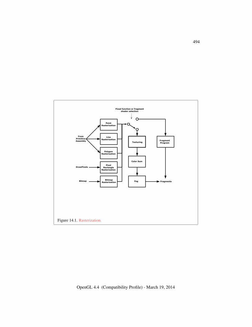
494
PointRasterization
PolygonRasterization
LineRasterization
BitmapRasterization
PixelRectangle
Rasterization
Fog
Color Sum
TexturingFragmentProgram
FromPrimitiveAssembly
DrawPixels
Bitmap Fragments
Fixed function or fragment shader selection
Figure 14.1. Rasterization.
OpenGL 4.4 (Compatibility Profile) - March 19, 2014
14.1. DISCARDING PRIMITIVES BEFORE RASTERIZATION 495
direction than the other. We assume that fragments are square, since it simplifiesantialiasing and texturing.
Several factors affect rasterization. Primitives may be discarded before ras-terization. Lines and polygons may be stippled. Points may be given differingdiameters and line segments differing widths. A point, line segment, or polygonmay be antialiased.
Rasterization only produces fragments corresponding to pixels in the frame-buffer. Fragments which would be produced by application of any of the primitiverasterization rules described below but which lie outside the framebuffer are notproduced, nor are they processed by any later stage of the GL, including any of theearly per-fragment tests described in section 14.9.
14.1 Discarding Primitives Before Rasterization
Primitives sent to vertex stream zero (see section 13.2) are processed further; prim-itives emitted to any other stream are discarded. When geometry shaders are dis-abled, all vertices are considered to be emitted to stream zero.
Primitives can be optionally discarded before rasterization by calling Enableand Disable with target RASTERIZER_DISCARD. When enabled, primitives arediscarded immediately before the rasterization stage, but after the optional trans-form feedback stage (see section 13.2). When disabled, primitives are passedthrough to the rasterization stage to be processed normally. When enabled,RASTERIZER_DISCARD also causes the Accum, Bitmap, CopyPixels, DrawPix-els, Clear, and ClearBuffer* commands to be ignored.
The state required to control primitive discard is a bit indicating whether dis-card is enabled or disabled. The initial value of primitive discard is FALSE.
14.2 Invariance
Consider a primitive p′ obtained by translating a primitive p through an offset (x, y)in window coordinates, where x and y are integers. As long as neither p′ nor p isclipped, it must be the case that each fragment f ′ produced from p′ is identical toa corresponding fragment f from p except that the center of f ′ is offset by (x, y)from the center of f .
14.3 Antialiasing
OpenGL 4.4 (Compatibility Profile) - March 19, 2014
14.3. ANTIALIASING 496
Antialiasing of a point, line, or polygon is effected in one of two ways dependingon whether the GL is in RGBA or color index mode.
In RGBA mode, the R, G, and B values of the rasterized fragment are leftunaffected, but the A value is multiplied by a floating-point value in the range[0, 1] that describes a fragment’s screen pixel coverage. The per-fragment stage ofthe GL can be set up to use the A value to blend the incoming fragment with thecorresponding pixel already present in the framebuffer.
In color index mode, the least significant b bits (to the left of the binary point)of the color index are used for antialiasing; b = min{4,m}, wherem is the numberof bits in the color index portion of the framebuffer. The antialiasing process setsthese b bits based on the fragment’s coverage value: the bits are set to zero for nocoverage and to all ones for complete coverage.
The details of how antialiased fragment coverage values are computed are dif-ficult to specify in general. The reason is that high-quality antialiasing may takeinto account perceptual issues as well as characteristics of the monitor on whichthe contents of the framebuffer are displayed. Such details cannot be addressedwithin the scope of this document. Further, the coverage value computed for afragment of some primitive may depend on the primitive’s relationship to a num-ber of grid squares neighboring the one corresponding to the fragment, and not juston the fragment’s grid square. Another consideration is that accurate calculationof coverage values may be computationally expensive; consequently we allow agiven GL implementation to approximate true coverage values by using a fast butnot entirely accurate coverage computation.
In light of these considerations, we chose to specify the behavior of exact an-tialiasing in the prototypical case that each displayed pixel is a perfect square ofuniform intensity. The square is called a fragment square and has lower left corner(x, y) and upper right corner (x+1, y+1). We recognize that this simple box filtermay not produce the most favorable antialiasing results, but it provides a simple,well-defined model.
A GL implementation may use other methods to perform antialiasing, subjectto the following conditions:
1. If f1 and f2 are two fragments, and the portion of f1 covered by some prim-itive is a subset of the corresponding portion of f2 covered by the primitive,then the coverage computed for f1 must be less than or equal to that com-puted for f2.
2. The coverage computation for a fragment f must be local: it may dependonly on f ’s relationship to the boundary of the primitive being rasterized. Itmay not depend on f ’s x and y coordinates.
OpenGL 4.4 (Compatibility Profile) - March 19, 2014
14.3. ANTIALIASING 497
Another property that is desirable, but not required, is:
3. The sum of the coverage values for all fragments produced by rasterizing aparticular primitive must be constant, independent of any rigid motions inwindow coordinates, as long as none of those fragments lies along windowedges.
In some implementations, varying degrees of antialiasing quality may be obtainedby providing GL hints (section 21.5), allowing a user to make an image qualityversus speed tradeoff.
14.3.1 Multisampling
Multisampling is a mechanism to antialias all GL primitives: points, lines, poly-gons, bitmaps, and images. The technique is to sample all primitives multiple timesat each pixel. The color sample values are resolved to a single, displayable coloreach time a pixel is updated, so the antialiasing appears to be automatic at theapplication level. Because each sample includes color, depth, and stencil informa-tion, the color (including texture operation), depth, and stencil functions performequivalently to the single-sample mode.
An additional buffer, called the multisample buffer, is added to the framebuffer.Pixel sample values, including color, depth, and stencil values, are stored in thisbuffer. Samples contain separate color values for each fragment color. Whenthe framebuffer includes a multisample buffer, it does not include depth or sten-cil buffers, even if the multisample buffer does not store depth or stencil values.Color buffers do coexist with the multisample buffer, however.
Multisample antialiasing is most valuable for rendering polygons, because itrequires no sorting for hidden surface elimination, and it correctly handles adjacentpolygons, object silhouettes, and even intersecting polygons. If only points orlines are being rendered, the “smooth” antialiasing mechanism provided by thebase GL may result in a higher quality image. This mechanism is designed toallow multisample and smooth antialiasing techniques to be alternated during therendering of a single scene.
If the value of SAMPLE_BUFFERS is one, the rasterization of all primitivesis changed, and is referred to as multisample rasterization. Otherwise, primitiverasterization is referred to as single-sample rasterization. The value of SAMPLE_-BUFFERS is a framebuffer-dependent constant, and is queried by calling GetInte-gerv with pname set to SAMPLE_BUFFERS.
During multisample rendering the contents of a pixel fragment are changed intwo ways. First, each fragment includes a coverage value with SAMPLES bits. The
OpenGL 4.4 (Compatibility Profile) - March 19, 2014

14.3. ANTIALIASING 498
value of SAMPLES is a framebuffer-dependent constant, and is queried by callingGetIntegerv with pname set to SAMPLES.
The location of a given sample is queried with the command
void GetMultisamplefv( enum pname, uint index,float *val );
pname must be SAMPLE_POSITION, and index corresponds to the sample forwhich the location should be returned. The sample location is returned as twofloating-point values in val[0] and val[1], each between 0 and 1, corresponding tothe x and y locations respectively in GL pixel space of that sample. (0.5, 0.5) thuscorresponds to the pixel center. If the multisample mode does not have fixed sam-ple locations, the returned values may only reflect the locations of samples withinsome pixels.
Errors
An INVALID_ENUM error is generated if pname is not SAMPLE_-
POSITION.An INVALID_VALUE error is generated if index is greater than or equal to
the value of SAMPLES.
Second, each fragment includes SAMPLES depth values and sets of associateddata, instead of the single depth value and set of associated data that is maintainedin single-sample rendering mode. An implementation may choose to assign thesame associated data to more than one sample. The location for evaluating suchassociated data can be anywhere within the pixel including the fragment center orany of the sample locations. The different associated data values need not all beevaluated at the same location. Each pixel fragment thus consists of integer x and ygrid coordinates, SAMPLES depth values and sets of associated data, and a coveragevalue with a maximum of SAMPLES bits.
Multisample rasterization is enabled or disabled by calling Enable or Disablewith target MULTISAMPLE.
If MULTISAMPLE is disabled, multisample rasterization of all primitives isequivalent to single-sample (fragment-center) rasterization, except that the frag-ment coverage value is set to full coverage. The color and depth values and thesets of texture coordinates may all be set to the values that would have been as-signed by single-sample rasterization, or they may be assigned as described belowfor multisample rasterization.
If MULTISAMPLE is enabled, multisample rasterization of all primitives differssubstantially from single-sample rasterization. It is understood that each pixel in
OpenGL 4.4 (Compatibility Profile) - March 19, 2014
14.3. ANTIALIASING 499
the framebuffer has SAMPLES locations associated with it. These locations areexact positions, rather than regions or areas, and each is referred to as a samplepoint. The sample points associated with a pixel may be located inside or outsideof the unit square that is considered to bound the pixel. Furthermore, the relativelocations of sample points may be identical for each pixel in the framebuffer, orthey may differ.
If MULTISAMPLE is enabled and the current program object includes a frag-ment shader with one or more input variables qualified with sample in, the dataassociated with those variables will be assigned independently. The values for eachsample must be evaluated at the location of the sample. The data associated withany other variables not qualified with sample in need not be evaluated indepen-dently for each sample.
If the sample locations differ per pixel, they should be aligned to window, notscreen, boundaries. Otherwise rendering results will be window-position specific.The invariance requirement described in section 14.2 is relaxed for all multisamplerasterization, because the sample locations may be a function of pixel location.
14.3.1.1 Sample Shading
Sample shading can be used to specify a minimum number of unique samples toprocess for each fragment. Sample shading is controlled by calling Enable orDisable with target SAMPLE_SHADING.
If MULTISAMPLE or SAMPLE_SHADING is disabled, sample shading has noeffect. Otherwise, an implementation must provide a minimum of
max(dmss× samplese, 1)
unique color values and sets of texture coordinates for each fragment, where mssis the value of MIN_SAMPLE_SHADING_VALUE and samples is the number ofsamples (the value of SAMPLES). These are associated with the samples in animplementation-dependent manner. The value of MIN_SAMPLE_SHADING_VALUEis specified by calling
void MinSampleShading( float value );
with value set to the desired minimum sample shading fraction. value is clampedto [0, 1] when specified. The sample shading fraction may be queried by callingGetFloatv with the symbolic constant MIN_SAMPLE_SHADING_VALUE.
When the sample shading fraction is 1.0, a separate set of colors and otherassociated data are evaluated for each sample, and each set of values is evaluatedat the sample location.
OpenGL 4.4 (Compatibility Profile) - March 19, 2014
14.4. POINTS 500
14.4 Points
A point is drawn by generating a set of fragments in the shape of a square or circlecentered around the vertex of the point. Each vertex has an associated point sizethat controls the size of that square or circle.
If no vertex, tessellation control, tessellation evaluation, or geometry shader isactive, then the rasterization of points is controlled with
void PointSize( float size );
size specifies the requested size of a point. The default value is 1.0.
Errors
An INVALID_VALUE error is generated if size is less than or equal to zero.
The requested point size is multiplied with a distance attenuation factor,clamped to a specified point size range, and further clamped to the implementation-dependent point size range to produce the derived point size:
derived size = clamp
(size×
√(1
a+ b ∗ d+ c ∗ d2
))where d is the eye-coordinate distance from the eye, (0, 0, 0, 1) in eye coordinates,to the vertex, and a, b, and c are distance attenuation function coefficients.
If multisampling is not enabled, the derived size is passed on to rasterization asthe point width.
If a vertex, tessellation control, tessellation evaluation, or geometry shader isactive and program point size mode is enabled, the derived point size is taken fromthe (potentially clipped) shader built-in gl_PointSize written by:
• the geometry shader, if active;
• the tessellation evaluation shader, if active and no geometry shader is active;
• the tessellation control shader, if active and no geometry or tessellation eval-uation shader is active; or
• the vertex shader, otherwise
and clamped to the implementation-dependent point size range. If the value writtento gl_PointSize is less than or equal to zero, or if no value was written to gl_-
PointSize, results are undefined. If a vertex, tessellation control, tessellation
OpenGL 4.4 (Compatibility Profile) - March 19, 2014
14.4. POINTS 501
evaluation, or geometry shader is active and program point size mode is disabled,the derived point size is taken from the point size state as specified by the PointSizecommand. In this case no distance attenuation is performed.
Program point size mode is enabled and disabled by calling Enable or Disablewith target PROGRAM_POINT_SIZE.
If multisampling is enabled, an implementation may optionally fade the pointalpha (see section 17.2) instead of allowing the point width to go below a giventhreshold. In this case, the width of the rasterized point is
width =
{derived size derived size ≥ thresholdthreshold otherwise
(14.1)
and the fade factor is computed as follows:
fade =
{1 derived size ≥ threshold(derived sizethreshold
)2otherwise
(14.2)
The point fade threshold, the distance attenuation function coefficients a, b,and c, and the bounds of the first point size range clamp are specified with
void PointParameter{if}( enum pname, T param );void PointParameter{if}v( enum pname, const T *params );
If pname is POINT_FADE_THRESHOLD_SIZE, then param specifies, orparams points to the point fade threshold. If pname is POINT_DISTANCE_-
ATTENUATION, then params points to the coefficients a, b, and c. If pname isPOINT_SIZE_MIN or POINT_SIZE_MAX, then param specifies, or params pointsto the lower or upper bound respectively to which the derived point size is clamped.If the lower bound is greater than the upper bound, the point size after clamping isundefined.
Data conversions are performed as specified in section 2.2.1.The point sprite texture coordinate origin is set with the PointParame-
ter* commands where pname is POINT_SPRITE_COORD_ORIGIN and param isLOWER_LEFT or UPPER_LEFT. The default value is UPPER_LEFT.
Errors
An INVALID_ENUM error is generated if pname is not POINT_FADE_-THRESHOLD_SIZE, POINT_DISTANCE_ATTENUATION, POINT_SIZE_MIN,POINT_SIZE_MAX, or POINT_SPRITE_COORD_ORIGIN.
An INVALID_VALUE error is generated if negative values are specifiedfor POINT_SIZE_MIN, POINT_SIZE_MAX, or POINT_FADE_THRESHOLD_-
OpenGL 4.4 (Compatibility Profile) - March 19, 2014
14.4. POINTS 502
SIZE.
Point antialiasing is enabled or disabled by calling Enable or Disable withtarget POINT_SMOOTH. The default state is for point antialiasing to be disabled.
Point sprites are enabled or disabled by calling Enable or Disable with tar-get POINT_SPRITE. The default state is for point sprites to be disabled. Whenpoint sprites are enabled, the state of the point antialiasing enable is ignored. In adeprecated context, point sprites are always enabled.
The point sprite texture coordinate replacement mode is set with one of theTexEnv* commands described in section 16.1, where target is POINT_SPRITE
and pname is COORD_REPLACE. The possible values for param are FALSE andTRUE. The default value for each texture coordinate set is for point sprite texturecoordinate replacement to be disabled.
14.4.1 Basic Point Rasterization
In the default state, a point is rasterized by truncating its xw and yw coordinates(recall that the subscripts indicate that these are x and y window coordinates) tointegers. This (x, y) address, along with data derived from the data associatedwith the vertex corresponding to the point, is sent as a single fragment to the per-fragment stage of the GL.
The effect of a point width other than 1.0 depends on the state of point antialias-ing and point sprites. If antialiasing and point sprites are disabled, the actual widthis determined by rounding the supplied width to the nearest integer, then clamp-ing it to the implementation-dependent maximum non-antialiased point width.This implementation-dependent value must be no less than the implementation-dependent maximum antialiased point width, rounded to the nearest integer value,and in any event no less than 1. If rounding the specified width results in the value0, then it is as if the value were 1. If the resulting width is odd, then the point
(x, y) = (bxwc+1
2, bywc+
1
2)
is computed from the vertex’s xw and yw, and a square grid of the odd width cen-tered at (x, y) defines the centers of the rasterized fragments (recall that fragmentcenters lie at half-integer window coordinate values). If the width is even, then thecenter point is
(x, y) = (bxw +1
2c, byw +
1
2c);
the rasterized fragment centers are the half-integer window coordinate valueswithin the square of the even width centered on (x, y). See figure 14.2.
OpenGL 4.4 (Compatibility Profile) - March 19, 2014
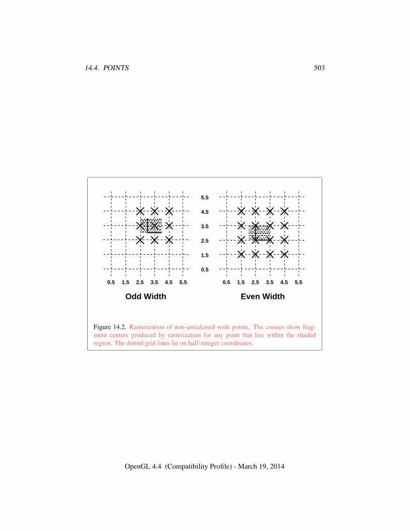
14.4. POINTS 503
� � �� � �
� � �� � �
Odd Width Even Width
3.5 4.5 5.52.51.5 3.5 4.5 5.52.51.5
1.5
2.5
3.5
4.5
0.50.5
0.5
5.5
Figure 14.2. Rasterization of non-antialiased wide points. The crosses show frag-ment centers produced by rasterization for any point that lies within the shadedregion. The dotted grid lines lie on half-integer coordinates.
OpenGL 4.4 (Compatibility Profile) - March 19, 2014
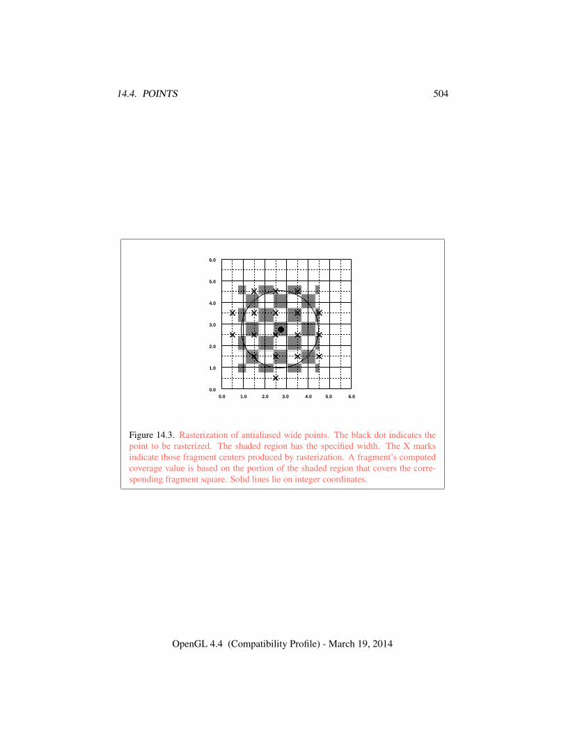
14.4. POINTS 504
� � � � � � � � � � � � � � �� � � � � � � � � � � � � � �� � � � � � � � � � � � � � �� � � � � � � � � � � � � � �� � � � � � � � � � � � � � �� � � � � � � � � � � � � � �� � � � � � � � � � � � � � �� � � � � � � � � � � � � � �� � � � � � � � � � � � � � �� � � � � � � � � � � � � � �� � � � � � � � � � � � � � �� � � � � � � � � � � � � � �� � � � � � � � � � � � � � �� � � � � � � � � � � � � � �� � � � � � � � � � � � � � �� � � � � � � � � � � � � � �
1.00.0 3.02.0 5.04.0 6.00.0
1.0
2.0
3.0
4.0
5.0
6.0
Figure 14.3. Rasterization of antialiased wide points. The black dot indicates thepoint to be rasterized. The shaded region has the specified width. The X marksindicate those fragment centers produced by rasterization. A fragment’s computedcoverage value is based on the portion of the shaded region that covers the corre-sponding fragment square. Solid lines lie on integer coordinates.
OpenGL 4.4 (Compatibility Profile) - March 19, 2014
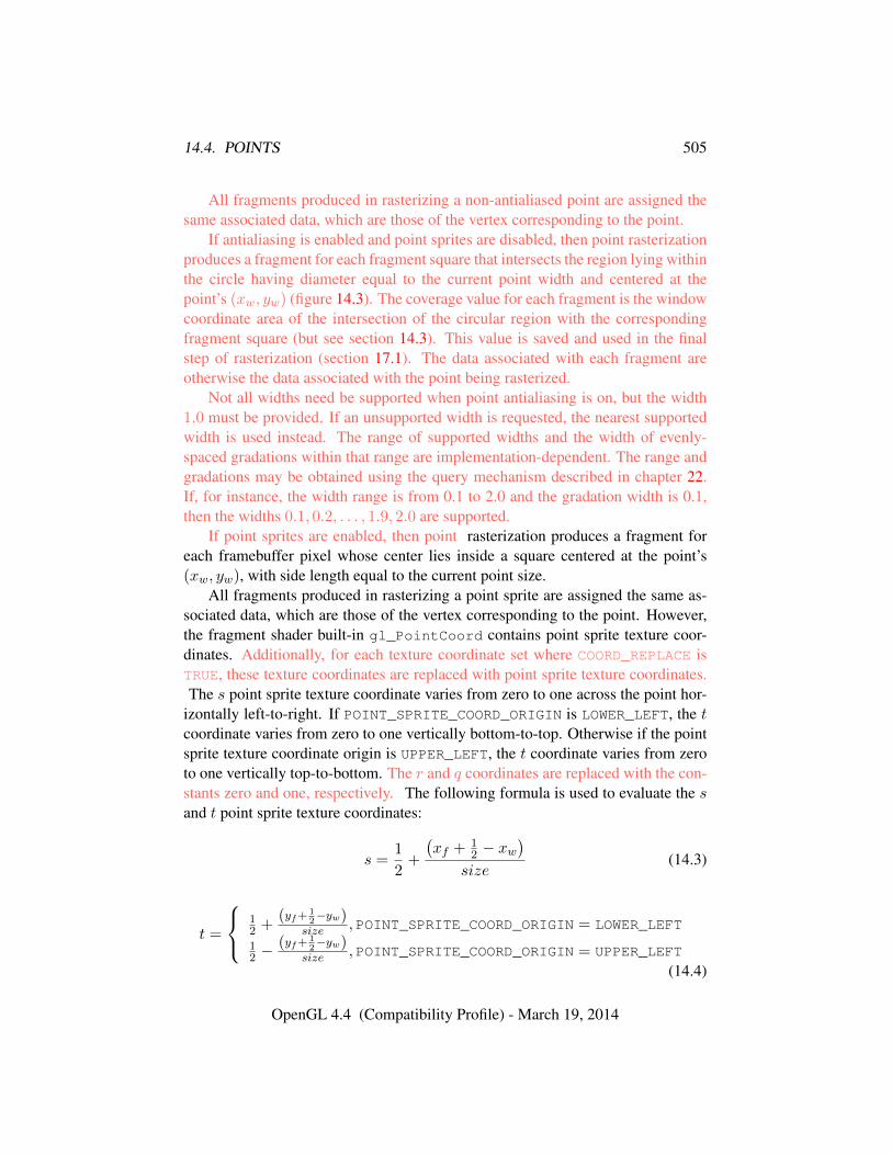
14.4. POINTS 505
All fragments produced in rasterizing a non-antialiased point are assigned thesame associated data, which are those of the vertex corresponding to the point.
If antialiasing is enabled and point sprites are disabled, then point rasterizationproduces a fragment for each fragment square that intersects the region lying withinthe circle having diameter equal to the current point width and centered at thepoint’s (xw, yw) (figure 14.3). The coverage value for each fragment is the windowcoordinate area of the intersection of the circular region with the correspondingfragment square (but see section 14.3). This value is saved and used in the finalstep of rasterization (section 17.1). The data associated with each fragment areotherwise the data associated with the point being rasterized.
Not all widths need be supported when point antialiasing is on, but the width1.0 must be provided. If an unsupported width is requested, the nearest supportedwidth is used instead. The range of supported widths and the width of evenly-spaced gradations within that range are implementation-dependent. The range andgradations may be obtained using the query mechanism described in chapter 22.If, for instance, the width range is from 0.1 to 2.0 and the gradation width is 0.1,then the widths 0.1, 0.2, . . . , 1.9, 2.0 are supported.
If point sprites are enabled, then point rasterization produces a fragment foreach framebuffer pixel whose center lies inside a square centered at the point’s(xw, yw), with side length equal to the current point size.
All fragments produced in rasterizing a point sprite are assigned the same as-sociated data, which are those of the vertex corresponding to the point. However,the fragment shader built-in gl_PointCoord contains point sprite texture coor-dinates. Additionally, for each texture coordinate set where COORD_REPLACE isTRUE, these texture coordinates are replaced with point sprite texture coordinates.The s point sprite texture coordinate varies from zero to one across the point hor-
izontally left-to-right. If POINT_SPRITE_COORD_ORIGIN is LOWER_LEFT, the tcoordinate varies from zero to one vertically bottom-to-top. Otherwise if the pointsprite texture coordinate origin is UPPER_LEFT, the t coordinate varies from zeroto one vertically top-to-bottom. The r and q coordinates are replaced with the con-stants zero and one, respectively. The following formula is used to evaluate the sand t point sprite texture coordinates:
s =1
2+
(xf + 1
2 − xw)
size(14.3)
t =
12 +
(yf+ 12−yw)
size , POINT_SPRITE_COORD_ORIGIN = LOWER_LEFT
12 −
(yf+ 12−yw)
size , POINT_SPRITE_COORD_ORIGIN = UPPER_LEFT
(14.4)
OpenGL 4.4 (Compatibility Profile) - March 19, 2014
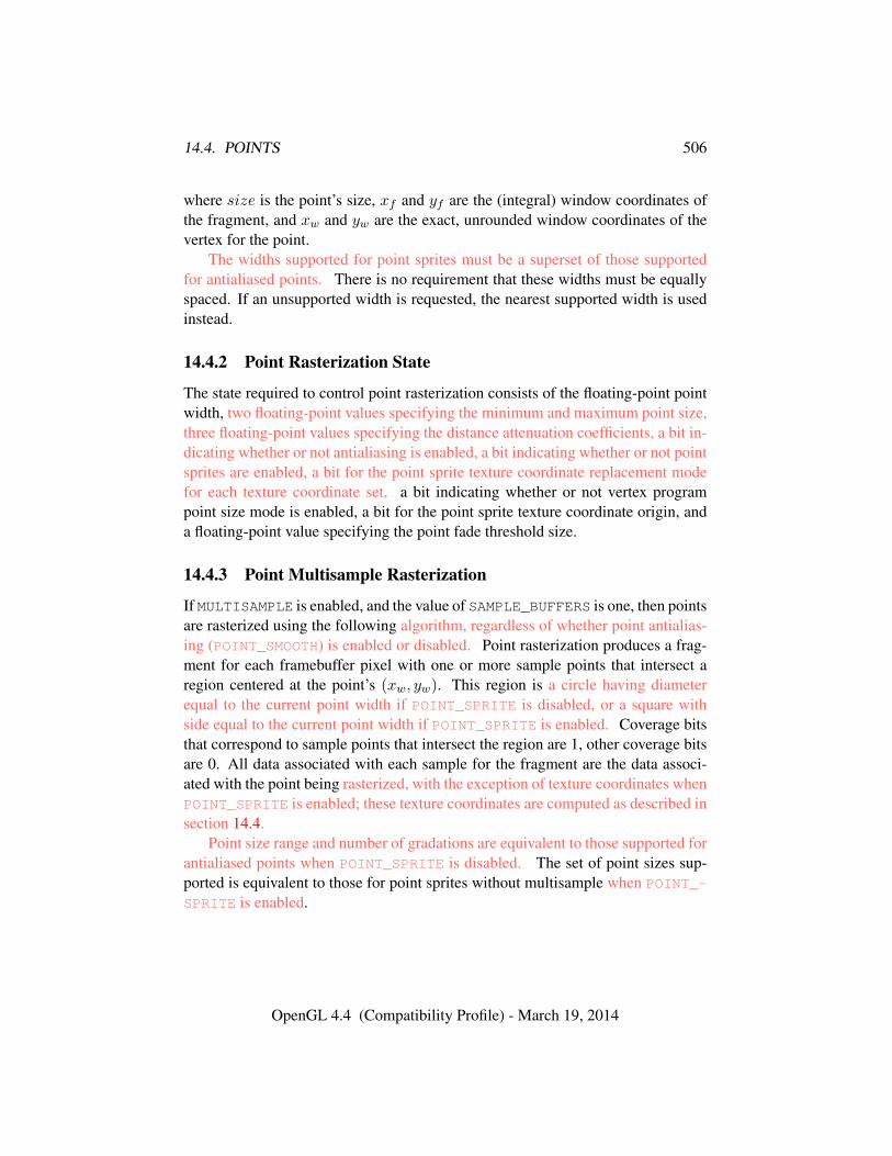
14.4. POINTS 506
where size is the point’s size, xf and yf are the (integral) window coordinates ofthe fragment, and xw and yw are the exact, unrounded window coordinates of thevertex for the point.
The widths supported for point sprites must be a superset of those supportedfor antialiased points. There is no requirement that these widths must be equallyspaced. If an unsupported width is requested, the nearest supported width is usedinstead.
14.4.2 Point Rasterization State
The state required to control point rasterization consists of the floating-point pointwidth, two floating-point values specifying the minimum and maximum point size,three floating-point values specifying the distance attenuation coefficients, a bit in-dicating whether or not antialiasing is enabled, a bit indicating whether or not pointsprites are enabled, a bit for the point sprite texture coordinate replacement modefor each texture coordinate set, a bit indicating whether or not vertex programpoint size mode is enabled, a bit for the point sprite texture coordinate origin, anda floating-point value specifying the point fade threshold size.
14.4.3 Point Multisample Rasterization
If MULTISAMPLE is enabled, and the value of SAMPLE_BUFFERS is one, then pointsare rasterized using the following algorithm, regardless of whether point antialias-ing (POINT_SMOOTH) is enabled or disabled. Point rasterization produces a frag-ment for each framebuffer pixel with one or more sample points that intersect aregion centered at the point’s (xw, yw). This region is a circle having diameterequal to the current point width if POINT_SPRITE is disabled, or a square withside equal to the current point width if POINT_SPRITE is enabled. Coverage bitsthat correspond to sample points that intersect the region are 1, other coverage bitsare 0. All data associated with each sample for the fragment are the data associ-ated with the point being rasterized, with the exception of texture coordinates whenPOINT_SPRITE is enabled; these texture coordinates are computed as described insection 14.4.
Point size range and number of gradations are equivalent to those supported forantialiased points when POINT_SPRITE is disabled. The set of point sizes sup-ported is equivalent to those for point sprites without multisample when POINT_-
SPRITE is enabled.
OpenGL 4.4 (Compatibility Profile) - March 19, 2014
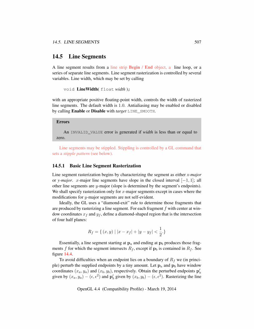
14.5. LINE SEGMENTS 507
14.5 Line Segments
A line segment results from a line strip Begin / End object, a line loop, or aseries of separate line segments. Line segment rasterization is controlled by severalvariables. Line width, which may be set by calling
void LineWidth( float width );
with an appropriate positive floating-point width, controls the width of rasterizedline segments. The default width is 1.0. Antialiasing may be enabled or disabledby calling Enable or Disable with target LINE_SMOOTH.
Errors
An INVALID_VALUE error is generated if width is less than or equal tozero.
Line segments may be stippled. Stippling is controlled by a GL command thatsets a stipple pattern (see below).
14.5.1 Basic Line Segment Rasterization
Line segment rasterization begins by characterizing the segment as either x-majoror y-major. x-major line segments have slope in the closed interval [−1, 1]; allother line segments are y-major (slope is determined by the segment’s endpoints).We shall specify rasterization only for x-major segments except in cases where themodifications for y-major segments are not self-evident.
Ideally, the GL uses a “diamond-exit” rule to determine those fragments thatare produced by rasterizing a line segment. For each fragment f with center at win-dow coordinates xf and yf , define a diamond-shaped region that is the intersectionof four half planes:
Rf = { (x, y) | |x− xf |+ |y − yf | <1
2.}
Essentially, a line segment starting at pa and ending at pb produces those frag-ments f for which the segment intersects Rf , except if pb is contained in Rf . Seefigure 14.4.
To avoid difficulties when an endpoint lies on a boundary of Rf we (in princi-ple) perturb the supplied endpoints by a tiny amount. Let pa and pb have windowcoordinates (xa, ya) and (xb, yb), respectively. Obtain the perturbed endpoints p′agiven by (xa, ya) − (ε, ε2) and p′b given by (xb, yb) − (ε, ε2). Rasterizing the line
OpenGL 4.4 (Compatibility Profile) - March 19, 2014
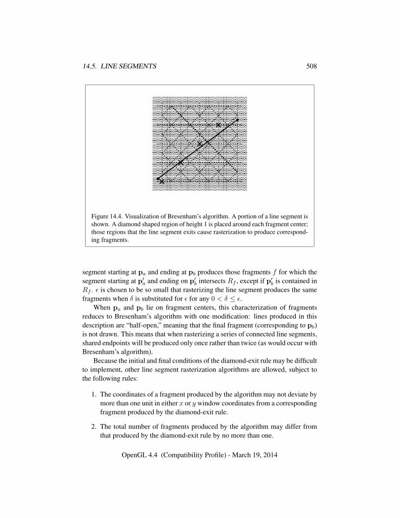
14.5. LINE SEGMENTS 508
� � � � �� � � � �� � � � �� � � � �
� � � � �� � � � �� � � � �� � � � �
� � � � �� � � � �� � � � �� � � � �
� � � � �� � � � �� � � � �� � � � �
� � � � �� � � � �� � � � �� � � � �
� � � � �� � � � �� � � � �� � � � �� � � � �� � � � �� � � � �� � � � �� � � � �� � � � �� � � � �� � � � �� � � � �� � � � �� � � � �� � � � �
� � � � �� � � � �� � � � �� � � � �� � � � �� � � � �� � � � �� � � � �
� � � � �� � � � �� � � � �� � � � �
� � � � �� � � � �� � � � �� � � � �� � � � �� � � � �� � � � �� � � � �� � � � �� � � � �� � � � �� � � � �� � � � �� � � � �� � � � �� � � � �� � � � �� � � � �� � � � �� � � � �
� � � � �� � � � �� � � � �� � � � �� � � � �� � � � �� � � � �� � � � �� � � � �� � � � �� � � � �� � � � �� � � � �� � � � �� � � � �� � � � �� � � � �� � � � �� � � � �� � � � �
Figure 14.4. Visualization of Bresenham’s algorithm. A portion of a line segment isshown. A diamond shaped region of height 1 is placed around each fragment center;those regions that the line segment exits cause rasterization to produce correspond-ing fragments.
segment starting at pa and ending at pb produces those fragments f for which thesegment starting at p′a and ending on p′b intersects Rf , except if p′b is contained inRf . ε is chosen to be so small that rasterizing the line segment produces the samefragments when δ is substituted for ε for any 0 < δ ≤ ε.
When pa and pb lie on fragment centers, this characterization of fragmentsreduces to Bresenham’s algorithm with one modification: lines produced in thisdescription are “half-open,” meaning that the final fragment (corresponding to pb)is not drawn. This means that when rasterizing a series of connected line segments,shared endpoints will be produced only once rather than twice (as would occur withBresenham’s algorithm).
Because the initial and final conditions of the diamond-exit rule may be difficultto implement, other line segment rasterization algorithms are allowed, subject tothe following rules:
1. The coordinates of a fragment produced by the algorithm may not deviate bymore than one unit in either x or y window coordinates from a correspondingfragment produced by the diamond-exit rule.
2. The total number of fragments produced by the algorithm may differ fromthat produced by the diamond-exit rule by no more than one.
OpenGL 4.4 (Compatibility Profile) - March 19, 2014
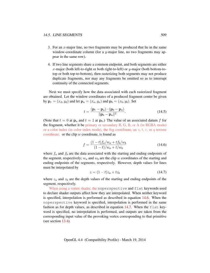
14.5. LINE SEGMENTS 509
3. For an x-major line, no two fragments may be produced that lie in the samewindow-coordinate column (for a y-major line, no two fragments may ap-pear in the same row).
4. If two line segments share a common endpoint, and both segments are eitherx-major (both left-to-right or both right-to-left) or y-major (both bottom-to-top or both top-to-bottom), then rasterizing both segments may not produceduplicate fragments, nor may any fragments be omitted so as to interruptcontinuity of the connected segments.
Next we must specify how the data associated with each rasterized fragmentare obtained. Let the window coordinates of a produced fragment center be givenby pr = (xd, yd) and let pa = (xa, ya) and pb = (xb, yb). Set
t =(pr − pa) · (pb − pa)
‖pb − pa‖2. (14.5)
(Note that t = 0 at pa and t = 1 at pb.) The value of an associated datum f forthe fragment, whether it be primary or secondary R, G, B, or A (in RGBA mode)or a color index (in color index mode), the fog coordinate, an s, t, r, or q texturecoordinate, or the clip w coordinate, is found as
f =(1− t)fa/wa + tfb/wb
(1− t)/wa + t/wb(14.6)
where fa and fb are the data associated with the starting and ending endpoints ofthe segment, respectively; wa and wb are the clip w coordinates of the starting andending endpoints of the segments, respectively. However, depth values for linesmust be interpolated by
z = (1− t)za + tzb (14.7)
where za and zb are the depth values of the starting and ending endpoints of thesegment, respectively.
When using a vertex shader, the noperspective and flat keywords usedto declare shader outputs affect how they are interpolated. When neither keywordis specified, interpolation is performed as described in equation 14.6. When thenoperspective keyword is specified, interpolation is performed in the samefashion as for depth values, as described in equation 14.7. When the flat key-word is specified, no interpolation is performed, and outputs are taken from thecorresponding input value of the provoking vertex corresponding to that primitive(see section 13.4).
OpenGL 4.4 (Compatibility Profile) - March 19, 2014
14.5. LINE SEGMENTS 510
14.5.2 Other Line Segment Features
We have just described the rasterization of non-antialiased line segments of widthone using the default line stipple of FFFF16. We now describe the rasterizationof line segments for general values of the line segment rasterization parameters.
14.5.2.1 Line Stipple
The command
void LineStipple( int factor, ushort pattern );
defines a line stipple. pattern is an unsigned short integer. The line stipple is takenfrom the lowest order 16 bits of pattern. It determines those fragments that are tobe drawn when the line is rasterized. factor is a count that is used to modify theeffective line stipple by causing each bit in pattern to be used factor times. factor isclamped to the range [1, 256]. Line stippling may be enabled or disabled by callingEnable or Disable with target LINE_STIPPLE. When disabled, it is as if the linestipple has its default value.
Line stippling masks certain fragments that are produced by rasterization sothat they are not sent to the per-fragment stage of the GL. The masking is achievedusing three parameters: the 16-bit line stipple p, the line repeat count r, and aninteger stipple counter s. Let
b = bs/rc mod 16,
Then a fragment is produced if the bth bit of p is 1, and not produced otherwise.The bits of p are numbered with 0 being the least significant and 15 being themost significant. The initial value of s is zero; s is incremented after productionof each fragment of a line segment (fragments are produced in order, beginning atthe starting point and working towards the ending point). s is reset to 0 whenevera Begin occurs, and before every line segment in a group of independent segments(as specified when Begin is invoked with LINES).
If the line segment has been clipped, then the value of s at the beginning of theline segment is indeterminate.
14.5.2.2 Wide Lines
The actual width of non-antialiased lines is determined by rounding the suppliedwidth to the nearest integer, then clamping it to the implementation-dependentmaximum non-antialiased line width. This implementation-dependent value mustbe no less than the implementation-dependent maximum antialiased line width,
OpenGL 4.4 (Compatibility Profile) - March 19, 2014
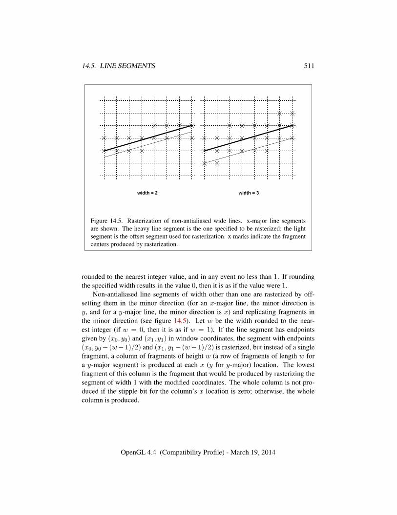
14.5. LINE SEGMENTS 511
width = 2 width = 3
Figure 14.5. Rasterization of non-antialiased wide lines. x-major line segmentsare shown. The heavy line segment is the one specified to be rasterized; the lightsegment is the offset segment used for rasterization. x marks indicate the fragmentcenters produced by rasterization.
rounded to the nearest integer value, and in any event no less than 1. If roundingthe specified width results in the value 0, then it is as if the value were 1.
Non-antialiased line segments of width other than one are rasterized by off-setting them in the minor direction (for an x-major line, the minor direction isy, and for a y-major line, the minor direction is x) and replicating fragments inthe minor direction (see figure 14.5). Let w be the width rounded to the near-est integer (if w = 0, then it is as if w = 1). If the line segment has endpointsgiven by (x0, y0) and (x1, y1) in window coordinates, the segment with endpoints(x0, y0− (w− 1)/2) and (x1, y1− (w− 1)/2) is rasterized, but instead of a singlefragment, a column of fragments of height w (a row of fragments of length w fora y-major segment) is produced at each x (y for y-major) location. The lowestfragment of this column is the fragment that would be produced by rasterizing thesegment of width 1 with the modified coordinates. The whole column is not pro-duced if the stipple bit for the column’s x location is zero; otherwise, the wholecolumn is produced.
OpenGL 4.4 (Compatibility Profile) - March 19, 2014
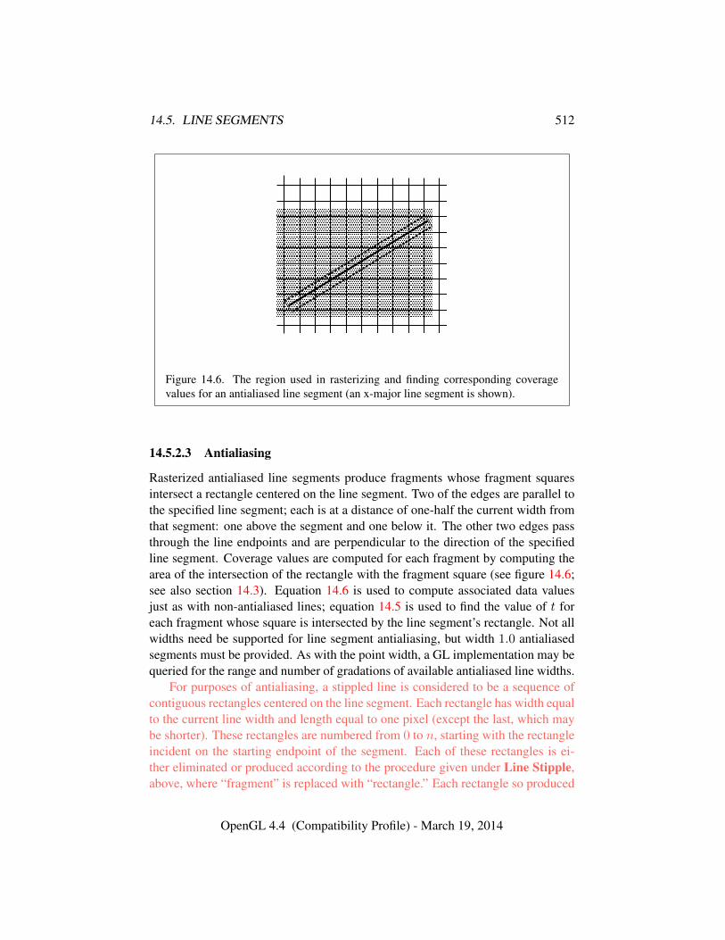
14.5. LINE SEGMENTS 512
� � � � � � � � � � � � � � � � � � � �� � � � � � � � � � � � � � � � � � � �� � � � � � � � � � � � � � � � � � � �� � � � � � � � � � � � � � � � � � � �� � � � � � � � � � � � � � � � � � � �� � � � � � � � � � � � � � � � � � � �� � � � � � � � � � � � � � � � � � � �� � � � � � � � � � � � � � � � � � � �� � � � � � � � � � � � � � � � � � � �� � � � � � � � � � � � � � � � � � � �� � � � � � � � � � � � � � � � � � � �� � � � � � � � � � � � � � � � � � � �� � � � � � � � � � � � � � � � � � � �� � � � � � � � � � � � � � � � � � � �
Figure 14.6. The region used in rasterizing and finding corresponding coveragevalues for an antialiased line segment (an x-major line segment is shown).
14.5.2.3 Antialiasing
Rasterized antialiased line segments produce fragments whose fragment squaresintersect a rectangle centered on the line segment. Two of the edges are parallel tothe specified line segment; each is at a distance of one-half the current width fromthat segment: one above the segment and one below it. The other two edges passthrough the line endpoints and are perpendicular to the direction of the specifiedline segment. Coverage values are computed for each fragment by computing thearea of the intersection of the rectangle with the fragment square (see figure 14.6;see also section 14.3). Equation 14.6 is used to compute associated data valuesjust as with non-antialiased lines; equation 14.5 is used to find the value of t foreach fragment whose square is intersected by the line segment’s rectangle. Not allwidths need be supported for line segment antialiasing, but width 1.0 antialiasedsegments must be provided. As with the point width, a GL implementation may bequeried for the range and number of gradations of available antialiased line widths.
For purposes of antialiasing, a stippled line is considered to be a sequence ofcontiguous rectangles centered on the line segment. Each rectangle has width equalto the current line width and length equal to one pixel (except the last, which maybe shorter). These rectangles are numbered from 0 to n, starting with the rectangleincident on the starting endpoint of the segment. Each of these rectangles is ei-ther eliminated or produced according to the procedure given under Line Stipple,above, where “fragment” is replaced with “rectangle.” Each rectangle so produced
OpenGL 4.4 (Compatibility Profile) - March 19, 2014
14.6. POLYGONS 513
is rasterized as if it were an antialiased polygon, described below (but culling, non-default settings of PolygonMode, and polygon stippling are not applied).
14.5.3 Line Rasterization State
The state required for line rasterization consists of the floating-point line width, abit indicating whether line antialiasing is on or off, a 16-bit line stipple, the linestipple repeat count, and a bit indicating whether stippling is enabled or disabled.In addition, during rasterization an integer stipple counter must be maintained toimplement line stippling. The initial value of the line width is 1.0. The initialstate of line segment antialiasing is disabled. The initial value of the line stipple isFFFF16 (a stipple of all ones). The initial value of the line stipple repeat count isone. The initial state of line stippling is disabled.
14.5.4 Line Multisample Rasterization
If MULTISAMPLE is enabled, and the value of SAMPLE_BUFFERS is one, then linesare rasterized using the following algorithm, regardless of whether line antialiasing(LINE_SMOOTH) is enabled or disabled. Line rasterization produces a fragment foreach framebuffer pixel with one or more sample points that intersect the rectangu-lar region that is described in the Antialiasing portion of section 14.5.2 (Other LineSegment Features). If line stippling is enabled, the rectangular region is subdividedinto adjacent unit-length rectangles, with some rectangles eliminated according tothe procedure given in section 14.5.2.1, where “fragment” is replaced by “rectan-gle”.
Coverage bits that correspond to sample points that intersect a retained rectan-gle are 1, other coverage bits are 0. Each depth value and set of associated datais produced by substituting the corresponding sample location into equation 14.5,then using the result to evaluate equation 14.7. An implementation may choose toassign the associated data to more than one sample by evaluating equation 14.5 atany location within the pixel including the fragment center or any one of the sam-ple locations, then substituting into equation 14.6. The different associated datavalues need not be evaluated at the same location.
Line width range and number of gradations are equivalent to those supportedfor antialiased lines.
14.6 Polygons
A polygon results from a triangle arising from a triangle strip, triangle fan, or seriesof separate triangles; a polygon primitive; or a quadrilateral arising from a quadri-
OpenGL 4.4 (Compatibility Profile) - March 19, 2014
14.6. POLYGONS 514
lateral strip, series of separate quadrilaterals, or Rect command. Like pointsand line segments, polygon rasterization is controlled by several variables. Poly-gon antialiasing is enabled or disabled by calling Enable or Disable with targetPOLYGON_SMOOTH. The analog to line segment stippling for polygons is polygonstippling, described below.
14.6.1 Basic Polygon Rasterization
The first step of polygon rasterization is to determine if the polygon is back-facingor front-facing. This determination is made based on the sign of the (clipped orunclipped) polygon’s area computed in window coordinates. One way to computethis area is
a =1
2
n−1∑i=0
xiwyi⊕1w − xi⊕1w yiw (14.8)
where xiw and yiw are the x and y window coordinates of the ith vertex of then-vertex polygon (vertices are numbered starting at zero for purposes of this com-putation) and i⊕ 1 is (i+ 1) mod n. The interpretation of the sign of this value iscontrolled with
void FrontFace( enum dir );
Setting dir to CCW (corresponding to counter-clockwise orientation of the pro-jected polygon in window coordinates) uses a as computed above. Setting dir toCW (corresponding to clockwise orientation) indicates that the sign of a should bereversed prior to use. Front face determination requires one bit of state, and isinitially set to CCW.
Errors
An INVALID_ENUM error is generated if dir is not CW or CCW.
If the sign of a (including the possible reversal of this sign as determined byFrontFace) is positive, the polygon is front-facing; otherwise, it is back-facing.This determination is used in conjunction with the CullFace enable bit and modevalue to decide whether or not a particular polygon is rasterized. The CullFacemode is set by calling
void CullFace( enum mode );
OpenGL 4.4 (Compatibility Profile) - March 19, 2014
14.6. POLYGONS 515
mode is a symbolic constant: one of FRONT, BACK or FRONT_AND_BACK. Cullingis enabled or disabled by calling Enable or Disable with target CULL_FACE. Front-facing polygons are rasterized if either culling is disabled or the CullFace mode isBACK while back-facing polygons are rasterized only if either culling is disabledor the CullFace mode is FRONT. The initial setting of the CullFace mode is BACK.Initially, culling is disabled.
Errors
An INVALID_ENUM error is generated if mode is not FRONT, BACK, orFRONT_AND_BACK.
The rule for determining which fragments are produced by polygon rasteriza-tion is called point sampling. The two-dimensional projection obtained by takingthe x and y window coordinates of the polygon’s vertices is formed. Fragmentcenters that lie inside of this polygon are produced by rasterization. Special treat-ment is given to a fragment whose center lies on a polygon boundary edge. Insuch a case we require that if two polygons lie on either side of a common edge(with identical endpoints) on which a fragment center lies, then exactly one of thepolygons results in the production of the fragment during rasterization.
As for the data associated with each fragment produced by rasterizing a poly-gon, we begin by specifying how these values are produced for fragments in atriangle. Define barycentric coordinates for a triangle. Barycentric coordinates area set of three numbers, a, b, and c, each in the range [0, 1], with a + b + c = 1.These coordinates uniquely specify any point p within the triangle or on the trian-gle’s boundary as
p = apa + bpb + cpc,
where pa, pb, and pc are the vertices of the triangle. a, b, and c can be found as
a =A(ppbpc)
A(papbpc), b =
A(ppapc)
A(papbpc), c =
A(ppapb)
A(papbpc),
where A(lmn) denotes the area in window coordinates of the triangle with verticesl, m, and n.
Denote an associated datum at pa, pb, or pc as fa, fb, or fc, respectively. Thenthe value f of a datum at a fragment produced by rasterizing a triangle is given by
f =afa/wa + bfb/wb + cfc/wc
a/wa + b/wb + c/wc(14.9)
where wa, wb and wc are the clip w coordinates of pa, pb, and pc, respectively.a, b, and c are the barycentric coordinates of the fragment for which the data are
OpenGL 4.4 (Compatibility Profile) - March 19, 2014
14.6. POLYGONS 516
produced. a, b, and c must correspond precisely to the exact coordinates of thecenter of the fragment. Another way of saying this is that the data associated witha fragment must be sampled at the fragment’s center. However, depth values forpolygons must be interpolated by
z = aza + bzb + czc (14.10)
where za, zb, and zc are the depth values of pa, pb, and pc, respectively.When using a vertex shader, the noperspective and flat keywords used
to declare shader outputs affect how they are interpolated. When neither keywordis specified, interpolation is performed as described in equation 14.9. When thenoperspective keyword is specified, interpolation is performed in the samefashion as for depth values, as described in equation 14.10. When the flat key-word is specified, no interpolation is performed, and outputs are taken from thecorresponding input value of the provoking vertex corresponding to that primitive(see section 13.4).
For a polygon with more than three edges, we require only that a convexcombination of the values of the datum at the polygon’s vertices can be used toobtain the value assigned to each fragment produced by the rasterization algorithm.That is, it must be the case that at every fragment
f =n∑
i=1
aifi
where n is the number of vertices in the polygon, fi is the value of the f at vertexi; for each i 0 ≤ ai ≤ 1 and
∑ni=1 ai = 1. The values of the ai may differ from
fragment to fragment, but at vertex i, aj = 0, j 6= i and ai = 1.One algorithm that achieves the required behavior is to triangulate a polygon
(without adding any vertices) and then treat each triangle individually as alreadydiscussed. A scan-line rasterizer that linearly interpolates data along each edgeand then linearly interpolates data across each horizontal span from edge to edgealso satisfies the restrictions (in this case, the numerator and denominator of equa-tion 14.9 should be iterated independently and a division performed for each frag-ment).
14.6.2 Stippling
Polygon stippling works much the same way as line stippling, masking out certainfragments produced by rasterization so that they are not sent to the next stage ofthe GL. This is the case regardless of the state of polygon antialiasing. Stippling iscontrolled with
OpenGL 4.4 (Compatibility Profile) - March 19, 2014
14.6. POLYGONS 517
void PolygonStipple( const ubyte *pattern );
pattern is a pointer to memory into which a 32× 32 pattern is packed. The patternis unpacked from memory according to the procedure given in section 18.1 forDrawPixels; it is as if the height and width passed to that command were both equalto 32, the type were BITMAP, and the format were COLOR_INDEX. The unpackedvalues (before any conversion or arithmetic would have been performed) form astipple pattern of zeros and ones.
If xw and yw are the window coordinates of a rasterized polygon fragment,then that fragment is sent to the next stage of the GL if and only if the bit of thepattern (xw mod 32, yw mod 32) is 1.
Polygon stippling may be enabled or disabled by calling Enable or Disablewith target POLYGON_STIPPLE. When disabled, it is as if the stipple pattern wereall ones.
14.6.2.1 Stipple Query
The command
void GetPolygonStipple( ubyte *pattern );
obtains the polygon stipple. The pattern is packed into pixel pack buffer or clientmemory according to the procedure given in section 18.2 for ReadPixels; it is as ifthe height and width passed to that command were both equal to 32, the type wereBITMAP, and the format were COLOR_INDEX.
14.6.3 Antialiasing
Polygon antialiasing rasterizes a polygon by producing a fragment wherever theinterior of the polygon intersects that fragment’s square. A coverage value is com-puted at each such fragment, and this value is saved to be applied as describedin section 17.1. An associated datum is assigned to a fragment by integrating thedatum’s value over the region of the intersection of the fragment square with thepolygon’s interior and dividing this integrated value by the area of the intersection.For a fragment square lying entirely within the polygon, the value of a datum at thefragment’s center may be used instead of integrating the value across the fragment.
Polygon stippling operates in the same way whether polygon antialiasing isenabled or not. The polygon point sampling rule defined in section 14.6.1, however,is not enforced for antialiased polygons.
OpenGL 4.4 (Compatibility Profile) - March 19, 2014

14.6. POLYGONS 518
14.6.4 Options Controlling Polygon Rasterization
The interpretation of polygons for rasterization is controlled using
void PolygonMode( enum face, enum mode );
face is one of FRONT, BACK, or FRONT_AND_BACK, indicating that the rasterizingmethod described by mode respectively replaces the rasterizing method for front-facing polygons, back-facing polygons, or both front- and back-facing polygons.mode is one of the symbolic constants POINT, LINE, or FILL. Calling Polygon-Mode with POINT causes certain vertices of a polygon to be treated, for rasteriza-tion purposes, as if they had been drawn with mode POINTS. The vertices selectedfor this treatment are those that have been tagged as having a polygon boundaryedge beginning on them (see section 10.1.17). LINE causes edges that are taggedas boundary to be rasterized as line segments. (The line stipple counter is resetat the beginning of the first rasterized edge of the polygon, but not for subsequentedges.) FILL is the default mode of polygon rasterization, corresponding to thedescription in sections 14.6.1, 14.6.2, and 14.6.3. Note that these modes affect onlythe final rasterization of polygons: in particular, a polygon’s vertices are lit, and thepolygon is clipped and possibly culled before these modes are applied.
Polygon antialiasing applies only to the FILL state of PolygonMode. ForPOINT or LINE, point antialiasing or line segment antialiasing, respectively, ap-ply.
14.6.5 Depth Offset
The depth values of all fragments generated by the rasterization of a polygon maybe offset by a single value that is computed for that polygon. The function thatdetermines this value is specified by calling
void PolygonOffset( float factor, float units );
factor scales the maximum depth slope of the polygon, and units scales animplementation-dependent constant that relates to the usable resolution of thedepth buffer. The resulting values are summed to produce the polygon offset value.Both factor and units may be either positive or negative.
The maximum depth slope m of a triangle is
m =
√(∂zw∂xw
)2
+
(∂zw∂yw
)2
(14.11)
OpenGL 4.4 (Compatibility Profile) - March 19, 2014
14.6. POLYGONS 519
where (xw, yw, zw) is a point on the triangle. m may be approximated as
m = max
{∣∣∣∣ ∂zw∂xw
∣∣∣∣ , ∣∣∣∣∂zw∂yw
∣∣∣∣} . (14.12)
If the polygon has more than three vertices, one or more values of m maybe used during rasterization. Each may take any value in the range [min,max],where min and max are the smallest and largest values obtained by evaluatingequation 14.11 or equation 14.12 for the triangles formed by all three-vertex com-binations.
The minimum resolvable difference r is an implementation-dependent param-eter that depends on the depth buffer representation. It is the smallest difference inwindow coordinate z values that is guaranteed to remain distinct throughout poly-gon rasterization and in the depth buffer. All pairs of fragments generated by therasterization of two polygons with otherwise identical vertices, but zw values thatdiffer by r, will have distinct depth values.
For fixed-point depth buffer representations, r is constant throughout the rangeof the entire depth buffer. For floating-point depth buffers, there is no single min-imum resolvable difference. In this case, the minimum resolvable difference for agiven polygon is dependent on the maximum exponent, e, in the range of z valuesspanned by the primitive. If n is the number of bits in the floating-point mantissa,the minimum resolvable difference, r, for the given primitive is defined as
r = 2e−n.
If no depth buffer is present, r is undefined.The offset value o for a polygon is
o = m× factor + r × units. (14.13)
m is computed as described above. If the depth buffer uses a fixed-point represen-tation, m is a function of depth values in the range [0, 1], and o is applied to depthvalues in the same range.
Boolean state values POLYGON_OFFSET_POINT, POLYGON_OFFSET_LINE,and POLYGON_OFFSET_FILL determine whether o is applied during the rasteri-zation of polygons in POINT, LINE, and FILL modes. These boolean state valuesare enabled and disabled as target values to the commands Enable and Disable.If POLYGON_OFFSET_POINT is enabled, o is added to the depth value of eachfragment produced by the rasterization of a polygon in POINT mode. Likewise,if POLYGON_OFFSET_LINE or POLYGON_OFFSET_FILL is enabled, o is added tothe depth value of each fragment produced by the rasterization of a polygon inLINE or FILL modes, respectively.
OpenGL 4.4 (Compatibility Profile) - March 19, 2014
14.6. POLYGONS 520
For fixed-point depth buffers, fragment depth values are always limited to therange [0, 1] by clamping after offset addition is performed. Fragment depth valuesare clamped even when the depth buffer uses a floating-point representation.
14.6.6 Polygon Multisample Rasterization
If MULTISAMPLE is enabled, and the value of SAMPLE_BUFFERS is one, then poly-gons are rasterized using the following algorithm, regardless of whether polygonantialiasing (POLYGON_SMOOTH) is enabled or disabled. Polygon rasterization pro-duces a fragment for each framebuffer pixel with one or more sample points thatsatisfy the point sampling criteria described in section 14.6.1, including the specialtreatment for sample points that lie on a polygon boundary edge. If a polygonis culled, based on its orientation and the CullFace mode, then no fragments areproduced during rasterization. Fragments are culled by the polygon stipple just asthey are for aliased and antialiased polygons.
Coverage bits that correspond to sample points that satisfy the point samplingcriteria are 1, other coverage bits are 0. Each associated datum is produced asdescribed in section 14.6.1, but using the corresponding sample location instead ofthe fragment center. An implementation may choose to assign the same associateddata values to more than one sample by barycentric evaluation using any locationwithin the pixel including the fragment center or one of the sample locations. Thecolor value and the set of texture coordinates need not be evaluated at the samelocation.
When using a vertex shader, the noperspective and flat qualifiers affecthow shader outputs are interpolated in the same fashion as described for for basicpolygon rasterization in section 14.6.1.
The rasterization described above applies only to the FILL state of Polygon-Mode. For POINT and LINE, the rasterizations described in sections 14.4.3 (PointMultisample Rasterization) and 14.5.4 (Line Multisample Rasterization) apply.
14.6.7 Polygon Rasterization State
The state required for polygon rasterization consists of a polygon stipple pattern,whether stippling is enabled or disabled, the current state of polygon antialiasing(enabled or disabled), the current values of the PolygonMode setting for each offront- and back-facing polygons, whether point, line, and fill mode polygon off-sets are enabled or disabled, and the factor and bias values of the polygon offsetequation. The initial stipple pattern is all ones; initially stippling is disabled. Theinitial setting of polygon antialiasing is disabled. The initial state for Polygon-Mode is FILL for both front- and back-facing polygons. The initial polygon offset
OpenGL 4.4 (Compatibility Profile) - March 19, 2014
14.7. CURRENT RASTER POSITION 521
factor and bias values are both 0; initially polygon offset is disabled for all modes.
14.7 Current Raster Position
The current raster position is used by commands that directly affect pixels inthe framebuffer, including Bitmap (see section 14.8) and DrawPixels (see sec-tion 18.1). These commands generate fragments, but bypass vertex transformationand primitive assembly. The current raster position, however, shares some of thecharacteristics of a vertex.
The current raster position is set using one of the commands
void RasterPos{234}{sifd}( T coords );void RasterPos{234}{sifd}v( const T *coords );
RasterPos4 takes four values indicating x, y, z, and w. RasterPos3 (or Raster-Pos2) is analogous, but sets only x, y, and z with w implicitly set to 1 (or only xand y with z implicitly set to 0 and w implicitly set to 1).
The coordinates are treated as if they were specified in a Vertex command. Ifa vertex shader is active, this vertex shader is executed using the x, y, z, and wcoordinates as the object coordinates of the vertex. Otherwise, the x, y, z, andw coordinates are transformed by the current model-view and projection matri-ces. These coordinates, along with current values, are used to generate primaryand secondary colors and texture coordinates just as is done for a vertex. The col-ors and texture coordinates so produced replace the colors and texture coordinatesstored in the current raster position’s associated data. If a vertex shader is ac-tive then the current raster distance is set to the value of the shader built-in outputgl_FogFragCoord. Otherwise, if the value of the fog source (see section 16.4)is FOG_COORD, then the current raster distance is set to the value of the currentfog coordinate. Otherwise, the current raster distance is set to the distance fromthe origin of the eye coordinate system to the vertex as transformed by only thecurrent model-view matrix. This distance may be approximated as discussed insection 16.4.
If depth clamping (see section 13.5) is enabled, then raster position zw is firstclamped to the range [min(n, f),max(n, f)], where n and f are the current nearand far depth range values (see section 13.6.1).
Since vertex shaders may be executed when the raster position is set, any at-tributes not written by the shader will result in undefined state in the current rasterposition. Vertex shaders should write all output variables that would be used whenrasterizing pixel primitives using the current raster position.
OpenGL 4.4 (Compatibility Profile) - March 19, 2014
14.7. CURRENT RASTER POSITION 522
The transformed coordinates are passed to clipping as if they represented apoint. If the “point” is not culled, then the projection to window coordinates iscomputed (section 13.6) and saved as the current raster position, and the valid bitis set. If the “point” is culled, the current raster position and its associated databecome indeterminate and the valid bit is cleared. Figure 14.7 summarizes thebehavior of the current raster position.
Alternately, the current raster position may be set by one of the WindowPoscommands:
void WindowPos{23}{sifd}( T coords );void WindowPos{23}{sifd}v( const T *coords );
WindowPos3 takes three values indicating x, y and z, while WindowPos2takes two values indicating x and y with z implicitly set to 0. The current rasterposition, (xw, yw, zw, wc), is defined by:
xw = x
yw = y
zw =
n, z ≤ 0
f, z ≥ 1
n+ z(f − n), otherwise
wc = 1
where n and f are the values passed to DepthRange (see section 13.6.1).Lighting, texture coordinate generation and transformation, and clipping are
not performed by the WindowPos functions. Instead, in RGBA mode, the currentraster color and secondary color are obtained from the current color and secondarycolor, respectively. If vertex color clamping is enabled, the current raster color andsecondary color are clamped to [0, 1]. In color index mode, the current raster colorindex is set to the current color index. The current raster texture coordinates are setto the current texture coordinates, and the valid bit is set.
If the value of the fog source is FOG_COORD_SRC, then the current raster dis-tance is set to the value of the current fog coordinate. Otherwise, the raster distanceis set to 0.
The current raster position requires six single-precision floating-point valuesfor its xw, yw, and zw window coordinates, itswc clip coordinate, its raster distance(used as the fog coordinate in raster processing), a single valid bit, four floating-point values to store the current RGBA color, four floating-point values to store thecurrent RGBA secondary color, one floating-point value to store the current color
OpenGL 4.4 (Compatibility Profile) - March 19, 2014
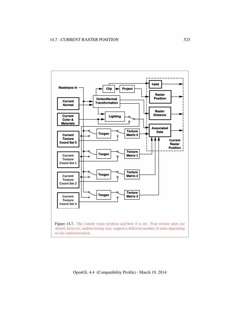
14.7. CURRENT RASTER POSITION 523
Rasterpos In
CurrentNormal
Lighting
Vertex/NormalTransformation
Clip Project
CurrentRaster
Position
Valid
RasterPosition
RasterDistance
AssociatedData
CurrentColor &
Materials
TextureMatrix 0Current
TextureCoord Set 0
Texgen
TextureMatrix 3Current
TextureCoord Set 3
Texgen
TextureMatrix 2Current
TextureCoord Set 2
Texgen
TextureMatrix 1Current
TextureCoord Set 1
Texgen
Figure 14.7. The current raster position and how it is set. Four texture units areshown; however, multitexturing may support a different number of units dependingon the implementation.
OpenGL 4.4 (Compatibility Profile) - March 19, 2014
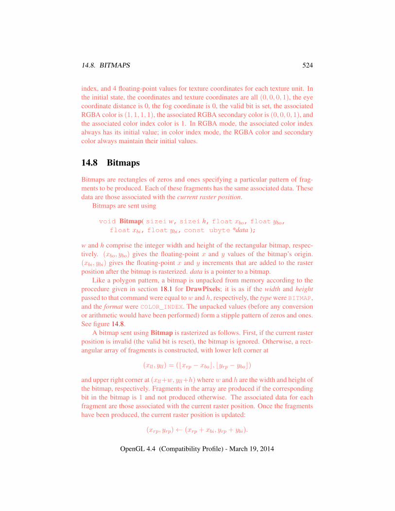
14.8. BITMAPS 524
index, and 4 floating-point values for texture coordinates for each texture unit. Inthe initial state, the coordinates and texture coordinates are all (0, 0, 0, 1), the eyecoordinate distance is 0, the fog coordinate is 0, the valid bit is set, the associatedRGBA color is (1, 1, 1, 1), the associated RGBA secondary color is (0, 0, 0, 1), andthe associated color index color is 1. In RGBA mode, the associated color indexalways has its initial value; in color index mode, the RGBA color and secondarycolor always maintain their initial values.
14.8 Bitmaps
Bitmaps are rectangles of zeros and ones specifying a particular pattern of frag-ments to be produced. Each of these fragments has the same associated data. Thesedata are those associated with the current raster position.
Bitmaps are sent using
void Bitmap( sizei w, sizei h, float xbo, float ybo,float xbi, float ybi, const ubyte *data );
w and h comprise the integer width and height of the rectangular bitmap, respec-tively. (xbo, ybo) gives the floating-point x and y values of the bitmap’s origin.(xbi, ybi) gives the floating-point x and y increments that are added to the rasterposition after the bitmap is rasterized. data is a pointer to a bitmap.
Like a polygon pattern, a bitmap is unpacked from memory according to theprocedure given in section 18.1 for DrawPixels; it is as if the width and heightpassed to that command were equal tow and h, respectively, the type were BITMAP,and the format were COLOR_INDEX. The unpacked values (before any conversionor arithmetic would have been performed) form a stipple pattern of zeros and ones.See figure 14.8.
A bitmap sent using Bitmap is rasterized as follows. First, if the current rasterposition is invalid (the valid bit is reset), the bitmap is ignored. Otherwise, a rect-angular array of fragments is constructed, with lower left corner at
(xll, yll) = (bxrp − xboc, byrp − yboc)
and upper right corner at (xll+w, yll+h) wherew and h are the width and height ofthe bitmap, respectively. Fragments in the array are produced if the correspondingbit in the bitmap is 1 and not produced otherwise. The associated data for eachfragment are those associated with the current raster position. Once the fragmentshave been produced, the current raster position is updated:
(xrp, yrp)← (xrp + xbi, yrp + ybi).
OpenGL 4.4 (Compatibility Profile) - March 19, 2014
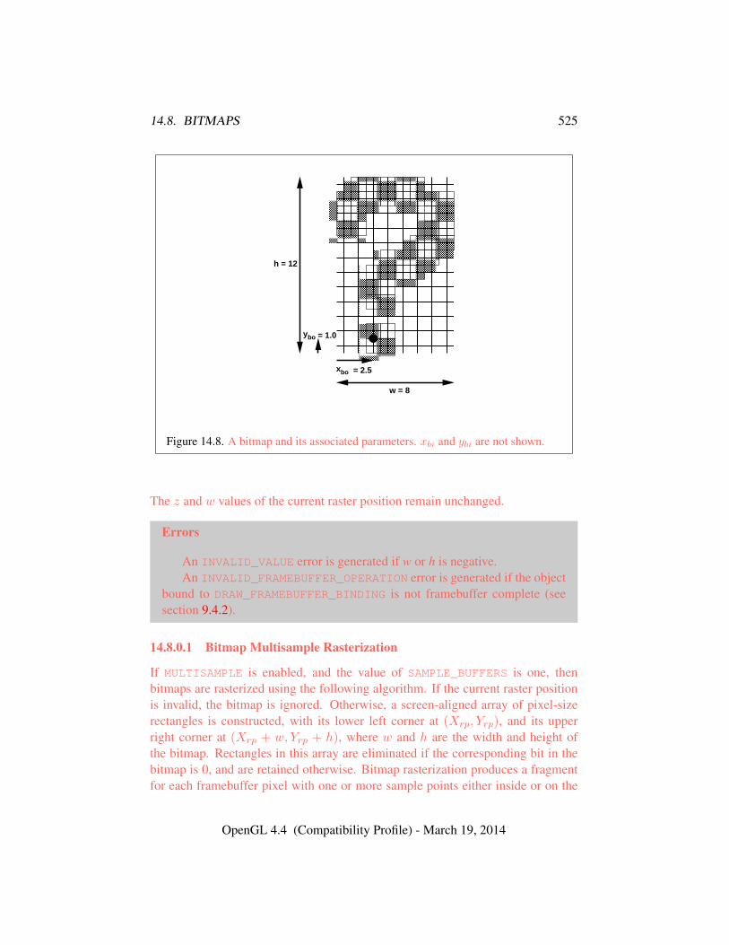
14.8. BITMAPS 525
� � �� � �� � �
� � �� � �� � �� � �
� � �� � �
� � �� � �� � �
� � �� � �� � �
� � �� � �� � �� � �
� � �� � �
� � �� � �� � �� � �
� � �� � �
� � �� � �� � �� � �
� � �� � �
� � �� � �� � �
� � �� � �� � �� � �
� � �� � �
� � �� � �� � �
� � �� � �� � �� � �
� � �� � �
� � �� � �� � �� � �
� � �� � �
� � �� � �� � �� � �� � �� � �
� � �� � �� � �
� � �� � �� � �
� � �� � �� � �
� � �� � �� � �
� � �� � �� � � � � �
� � �� � �
� � �� � �� � �
� � �� � �� � �
! ! !! ! !! ! !
" " "" " "" " "
# # ## # ## # #
$ $ $$ $ $$ $ $
% % %% % %% % %
& & && & && & &
' ' '' ' '' ' '
h = 12
w = 8
ybo = 1.0
xbo = 2.5
Figure 14.8. A bitmap and its associated parameters. xbi and ybi are not shown.
The z and w values of the current raster position remain unchanged.
Errors
An INVALID_VALUE error is generated if w or h is negative.An INVALID_FRAMEBUFFER_OPERATION error is generated if the object
bound to DRAW_FRAMEBUFFER_BINDING is not framebuffer complete (seesection 9.4.2).
14.8.0.1 Bitmap Multisample Rasterization
If MULTISAMPLE is enabled, and the value of SAMPLE_BUFFERS is one, thenbitmaps are rasterized using the following algorithm. If the current raster positionis invalid, the bitmap is ignored. Otherwise, a screen-aligned array of pixel-sizerectangles is constructed, with its lower left corner at (Xrp, Yrp), and its upperright corner at (Xrp + w, Yrp + h), where w and h are the width and height ofthe bitmap. Rectangles in this array are eliminated if the corresponding bit in thebitmap is 0, and are retained otherwise. Bitmap rasterization produces a fragmentfor each framebuffer pixel with one or more sample points either inside or on the
OpenGL 4.4 (Compatibility Profile) - March 19, 2014
14.9. EARLY PER-FRAGMENT TESTS 526
bottom or left edge of a retained rectangle.Coverage bits that correspond to sample points either inside or on the bottom
or left edge of a retained rectangle are 1, other coverage bits are 0. The associateddata for each sample are those associated with the current raster position. Once thefragments have been produced, the current raster position is updated exactly as itis in the single-sample rasterization case.
14.9 Early Per-Fragment Tests
Once fragments are produced by rasterization, a number of per-fragment operationsmay be performed prior to fragment shader execution. If a fragment is discardedduring any of these operations, it will not be processed by any subsequent stage,including fragment shader execution.
Up to five operations are performed on each fragment, in the following order:
• the pixel ownership test (see section 17.3.1);
• the scissor test (see section 17.3.2);
• the stencil test (see section 17.3.5);
• the depth buffer test (see section 17.3.6); and
• occlusion query sample counting (see section 17.3.7).
The pixel ownership and scissor tests are always performed.The other operations are performed if and only if early fragment tests are en-
abled in the active fragment shader (see section 15.2). When early per-fragmentoperations are enabled, the stencil test, depth buffer test, and occlusion query sam-ple counting operations are performed prior to fragment shader execution, and thestencil buffer, depth buffer, and occlusion query sample counts will be updated ac-cordingly. When early per-fragment operations are enabled, these operations willnot be performed again after fragment shader execution. When there is no activeprogram, the active program has no fragment shader, or the active program waslinked with early fragment tests disabled, these operations are performed only af-ter fragment program execution, in the order described in chapter 9.
If early fragment tests are enabled, any depth value computed by the fragmentshader has no effect. Additionally, the depth buffer, stencil buffer, and occlusionquery sample counts may be updated even for fragments or samples that would bediscarded after fragment shader execution due to per-fragment operations such asalpha or alpha-to-coverage tests.
OpenGL 4.4 (Compatibility Profile) - March 19, 2014
Chapter 15
Programmable FragmentProcessing
When the program object currently in use for the fragment stage (see section 7.3)includes a fragment shader, its shader is considered active and is used to processfragments resulting from rasterization (see section 14).
If the current fragment stage program object has no fragment shader, or no frag-ment program object is current for the fragment stage, the fixed-function fragmentprocessing operations described in chapter 16 are used instead.
A fragment shader only applies when the GL is in RGBA mode. Its operationin color index mode is undefined.
Results of rasterization are undefined if any of the selected draw buffers of thedraw framebuffer have an integer format and no fragment shader is active.
The processed fragments resulting from fragment shader execution are thenfurther processed and written to the framebuffer as described in chapter 17.
15.1 Fragment Shader Variables
Fragment shaders can access uniforms belonging to the current program object.Limits on uniform storage and methods for manipulating uniforms are described insection 7.6.
Fragment shaders also have access to samplers to perform texturing operations,as described in section 7.10.
Fragment shaders can read input variables or inputs that correspond to theattributes of the fragments produced by rasterization.
The OpenGL Shading Language Specification defines a set of built-in inputsthat can be be accessed by a fragment shader. These built-in inputs include data
527
15.1. FRAGMENT SHADER VARIABLES 528
associated with a fragment that are used for fixed-function fragment processing,such as the fragment’s color, secondary color, texture coordinates, fog coordinate,eye z coordinate, and position.
Additionally, the previous active shader stage (if fixed-function vertex process-ing is not being used) may define one or more output variables (see section 11.1.2.1and the OpenGL Shading Language Specification). The values of these user-defined outputs are, if not flat shaded, interpolated across the primitive being ren-dered. The results of these interpolations are available when inputs of the samename are defined in the fragment shader.
User-defined inputs are not saved in the current raster position. When process-ing fragments generated by the rasterization of a pixel rectangle or bitmap, valuesof user-defined inputs are undefined. Built-in inputs have well-defined values.
When interpolating input variables, the default screen-space location at whichthese variables are sampled is defined in previous rasterization sections. Thedefault location may be overriden by interpolation qualifiers. When interpolat-ing variables declared using centroid in, the variable is sampled at a locationwithin the pixel covered by the primitive generating the fragment. When interpo-lating variables declared using sample in when MULTISAMPLE is enabled, thefragment shader will be invoked separately for each covered sample and the vari-able will be sampled at the corresponding sample point.
Additionally, built-in fragment shader functions provide further fine-grainedcontrol over interpolation. The built-in functions interpolateAtCentroid
and interpolateAtSample will sample variables as though they were declaredwith the centroid or sample qualifiers, respectively. The built-in functioninterpolateAtOffset will sample variables at a specified (x, y) offset relativeto the center of the pixel. The range and granularity of offsets supported by thisfunction is implementation-dependent. If either component of the specified off-set is less than the value of MIN_FRAGMENT_INTERPOLATION_OFFSET or greaterthan the value of MAX_FRAGMENT_INTERPOLATION_OFFSET, the position usedto interpolate the variable is undefined. Not all values of offset may be supported;x and y offsets may be rounded to fixed-point values with the number of fractionbits given by the value of the implementation-dependent constant FRAGMENT_-INTERPOLATION_OFFSET_BITS.
A fragment shader can also write to output variables. Values written to theseoutputs are used in the subsequent per-fragment operations. Output variables canbe used to write floating-point, integer or unsigned integer values destined forbuffers attached to a framebuffer object, or destined for color buffers attached to thedefault framebuffer. Section 15.2.3 describes how to direct these values to buffers.
OpenGL 4.4 (Compatibility Profile) - March 19, 2014
15.2. SHADER EXECUTION 529
15.2 Shader Execution
If there is an active program object present for the fragment stage, the executablecode for that program is used to process incoming fragments that are the result ofrasterization, instead of the fixed-function method described in chapter 16.
Following shader execution, the fixed-function operations described in chap-ter 17 are performed.
Special considerations for fragment shader execution are described in the fol-lowing sections.
15.2.1 Texture Access
Section 11.1.3.1 describes texture lookup functionality accessible to a vertexshader. The texel fetch and texture size query functionality described there alsoapplies to fragment shaders.
When a texture lookup is performed in a fragment shader, the GL computesthe filtered texture value τ in the manner described in sections 8.14 and 8.15, andconverts it to a texture base colorCb as shown in table 16.1 (section 16.1), followedby application of the texture swizzle as described in section 16.1 to compute thetexture source color Cs and As.
The resulting four-component vector (Rs, Gs, Bs, As) is returned to the frag-ment shader. For the purposes of level-of-detail calculations, the derivatives du
dx , dudy ,
dvdx , dv
dy , dwdx and dw
dy may be approximated by a differencing algorithm as describedin section 8.13.1(“Derivative Functions”) of the OpenGL Shading Language Spec-ification.
Texture lookups involving textures with depth and/or stencil component dataare performed as described in section 11.1.3.5.
•
•
•
15.2.2 Shader Inputs
The OpenGL Shading Language Specification describes the values that are avail-able as inputs to the fragment shader.
The built-in variable gl_FragCoord holds the fragment coordinate(xf yf zf wf
)for the fragment. Computing the fragment coordinate depends
OpenGL 4.4 (Compatibility Profile) - March 19, 2014
15.2. SHADER EXECUTION 530
on the fragment processing pixel-center and origin conventions (discussed below)as follows:
xf =
{xw − 1
2 , pixel-center convention is integerxw, otherwise
y′f =
{H − yw, origin convention is upper-leftyw, otherwise
yf =
{y′f −
12 , pixel-center convention is integer
y′f otherwise
zf = zw
wf =1
wc
(15.1)
where(xw yw zw
)is the fragment’s window-space position,wc is thew compo-
nent of the fragment’s clip-space position, and H is the window’s height in pixels.Note that zw already has a polygon offset added in, if enabled (see section 14.6.5).zf must be precisely zero or one in the case where zw is either zero or one, respec-tively. The 1
w value is computed from the wc coordinate (see section 13.6), whichis the result of the product of the projection matrix and the vertex’s eye coordinates.
Unless otherwise specified by layout qualifiers in the fragment shader (seesection 4.4.1.3(“Fragment Shader Inputs”) of the OpenGL Shading LanguageSpecification), the fragment processing pixel-center convention is half-integer andthe fragment processing origin convention is lower-left.
The built-in variables gl_Color and gl_SecondaryColor hold the R, G,B, and A components, respectively, of the fragment color and secondary color.If the primary color or the secondary color components are represented by theGL as fixed-point values, they undergo an implied conversion to floating-point.This conversion must leave the values zero and one invariant. Floating-point colorcomponents (resulting from a disabled vertex color clamp) are unmodified.
The built-in variable gl_FrontFacing is set to TRUE if the fragment is gener-ated from a front-facing primitive, and FALSE otherwise. For fragments generatedfrom quadrilateral, polygon, or triangle primitives (including ones resulting fromprimitives rendered as points or lines), the determination is made by examining thesign of the area computed by equation 14.8 of section 14.6.1 (including the possi-ble reversal of this sign controlled by FrontFace). If the sign is positive, fragmentsgenerated by the primitive are front-facing; otherwise, they are back-facing. Allother fragments are considered front-facing.
OpenGL 4.4 (Compatibility Profile) - March 19, 2014
15.2. SHADER EXECUTION 531
If a geometry shader is active, the built-in variable gl_PrimitiveID con-tains the ID value emitted by the geometry shader for the provoking vertex. If nogeometry shader is active, gl_PrimitiveID contains the number of primitivesprocessed by the rasterizer since the last drawing command was called. The firstprimitive generated by a drawing command is numbered zero, and the primitive IDcounter is incremented after every individual point, line, or polygon primitive isprocessed. For polygons drawn in point or line mode, the primitive ID counter isincremented only once, even though multiple points or lines may be drawn.
For QUADS and QUAD_STRIP primitives that are decomposed into triangles, theprimitive ID is incremented after each complete quad is processed.
Restarting a primitive using the primitive restart index (see section 10.3) hasno effect on the primitive ID counter.
The value of gl_PrimitiveID is undefined for fragments generated byPOLYGON primitives or from DrawPixels or Bitmap commands. Additionally,gl_PrimitiveID is only defined under the same conditions that gl_VertexIDis defined, as described under “Shader Inputs” in section 11.1.3.9.
The built-in variable gl_SampleMaskIn is an integer array holding bitfieldsindicating the set of fragment samples covered by the primitive corresponding tothe fragment shader invocation. The number of elements in the array is⌈ s
32
⌉,
where s is the maximum number of color samples supported by the implementa-tion. Bit n of element w in the array is set if and only if the sample numbered32w + n is considered covered for this fragment shader invocation. When render-ing to a non-multisample buffer, or if multisample rasterization is disabled, all bitsare zero except for bit zero of the first array element. That bit will be one if thepixel is covered and zero otherwise. Bits in the sample mask corresponding to cov-ered samples that will be killed due to SAMPLE_COVERAGE or SAMPLE_MASK willnot be set (see section 17.3.3). When per-sample shading is active due to the useof a fragment input qualified by sample, only the bit for the current sample is setin gl_SampleMaskIn. When state specifies multiple fragment shader invocationsfor a given fragment, the sample mask for any single fragment shader invocationmay specify a subset of the covered samples for the fragment. In this case, the bitcorresponding to each covered sample will be set in exactly one fragment shaderinvocation.
The built-in read-only variable gl_SampleID is filled with the sample num-ber of the sample currently being processed. This variable is in the range zeroto gl_NumSamples minus one, where gl_NumSamples is the total number ofsamples in the framebuffer, or one if rendering to a non-multisample framebuffer.
OpenGL 4.4 (Compatibility Profile) - March 19, 2014
15.2. SHADER EXECUTION 532
Using this variable in a fragment shader causes the entire shader to be evaluatedper-sample. When rendering to a non-multisample buffer, or if multisample ras-terization is disabled, gl_SampleID will always be zero. gl_NumSamples is thesample count of the framebuffer regardless of whether multisample rasterization isenabled or not.
The built-in read-only variable gl_SamplePosition contains the position ofthe current sample within the multi-sample draw buffer. The x and y componentsof gl_SamplePosition contain the sub-pixel coordinate of the current sampleand will have values in the range [0, 1]. The sub-pixel coordinates of the center ofthe pixel are always (0.5, 0.5). Using this variable in a fragment shader causes theentire shader to be evaluated per-sample. When rendering to a non-multisamplebuffer, or if multisample rasterization is disabled, gl_SamplePosition will al-ways be (0.5, 0.5).
Similarly to the limit on geometry shader output components (see sec-tion 11.3.4.5), there is a limit on the number of components of built-in anduser-defined input variables that can be read by the fragment shader, given bythe value of the implementation-dependent constant MAX_FRAGMENT_INPUT_-COMPONENTS.
When a program is linked, all components of any input variables read by afragment shader will count against this limit. A program whose fragment shaderexceeds this limit may fail to link, unless device-dependent optimizations are ableto make the program fit within available hardware resources.
Component counting rules for different variable types and variable declarationsare the same as for MAX_VERTEX_OUTPUT_COMPONENTS. (see section 11.1.2.1).
15.2.3 Shader Outputs
The OpenGL Shading Language Specification describes the values that may beoutput by a fragment shader. These outputs are split into two categories, user-defined outputs and the built-in outputs gl_FragColor, gl_FragData[n],gl_FragDepth and gl_SampleMask.
If fragment color clamping is enabled and the color buffer has an unsigned nor-malized fixed-point, signed normalized fixed-point, or floating-point format, the fi-nal fragment color, fragment data, or output values written by a fragment shader areclamped to the range [0, 1]. Only user-defined outputs declared as a floating-pointtype are clamped and may be converted. If fragment color clamping is disabled, orthe color buffer has an integer format, the final fragment color, fragment data, oroutput values are not modified. For fixed-point depth buffers, the final fragmentdepth written by a fragment shader is first clamped to [0, 1] and then converted tofixed-point as if it were a window z value (see section 13.6.1). For floating-point
OpenGL 4.4 (Compatibility Profile) - March 19, 2014
15.2. SHADER EXECUTION 533
depth buffers, conversion is not performed but clamping is. Note that the depthrange computation is not applied here, only the conversion to fixed-point.
The built-in integer array gl_SampleMask can be used to change the samplecoverage for a fragment from within the shader. The number of elements in thearray is ⌈ s
32
⌉,
where s is the maximum number of color samples supported by the implemen-tation. If bit n of element w in the array is set to zero, sample 32w + n shouldbe considered uncovered for the purposes of multisample fragment operations (seesection 17.3.3). Modifying the sample mask in this way may exclude covered sam-ples from being processed further at a per-fragment granularity. However, settingsample mask bits to one will never enable samples not covered by the originalprimitive. If the fragment shader is being evaluated at any frequency other thanper-fragment, bits of the sample mask not corresponding to the current fragmentshader invocation are ignored.
Color values written by a fragment shader may be floating-point, signed inte-ger, or unsigned integer. If the color buffer has a signed or unsigned normalizedfixed-point format, color values are assumed to be floating-point and are convertedto fixed-point as described in equations 2.4 or 2.3, respectively; otherwise no typeconversion is applied. If the values written by the fragment shader do not matchthe format(s) of the corresponding color buffer(s), the result is undefined.
Writing to gl_FragColor specifies the fragment color (color number zero)that will be used by subsequent stages of the pipeline. Writing to gl_-
FragData[n] specifies the value of fragment color number n. Any colors, orcolor components, associated with a fragment that are not written by the fragmentshader are undefined.
A fragment shader may not statically assign values to more than one of gl_-FragColor, gl_FragData[n], and any user-defined output variable. In thiscase, a compile or link error will result. A shader statically assigns a value toa variable if, after pre-processing, it contains a statement that would write to thevariable, whether or not run-time flow of control will cause that statement to beexecuted.
Writing to gl_FragDepth specifies the depth value for the fragment beingprocessed. If the active fragment shader does not statically assign a value to gl_-
FragDepth, then the depth value generated during rasterization is used by sub-sequent stages of the pipeline. Otherwise, the value assigned to gl_FragDepth
is used, and is undefined for any fragments where statements assigning a value togl_FragDepth are not executed. Thus, if a shader statically assigns a value togl_FragDepth, then it is responsible for always writing it.
OpenGL 4.4 (Compatibility Profile) - March 19, 2014
15.2. SHADER EXECUTION 534
The binding of a user-defined output variable to components of a fragmentcolor number can be specified explicitly in shader text or using the command
void BindFragDataLocationIndexed( uint program,uint colorNumber, uint index, const char * name );
specifies that the output variable name in program should be bound to fragmentcolor colorNumber when the program is next linked. index may be zero or one tospecify that the color be used as either the first or second color input to the blendequation, respectively, as described in section 17.3.8.
If name was bound previously, its assigned binding is replaced with colorNum-ber. name must be a null-terminated string.
Errors
An INVALID_VALUE error is generated if program is not the name of ei-ther a program or shader object.
An INVALID_OPERATION error is generated if program is the name of ashader object.
An INVALID_VALUE error is generated if index is greater than one, ifcolorNumber is greater than or equal to the value of MAX_DRAW_BUFFERSand index is zero, or if colorNumber is greater than or equal to the value ofMAX_DUAL_SOURCE_DRAW_BUFFERS and index is greater than or equal toone.
The command
void BindFragDataLocation( uint program,uint colorNumber, const char * name );
is equivalent to
BindFragDataLocationIndexed(program, colorNumber, 0, name);
BindFragDataLocation has no effect until the program is linked. In particular,it doesn’t modify the bindings of outputs in a program that has already been linked.
Errors
An INVALID_OPERATION error is generated if name starts with the re-served gl_ prefix.
OpenGL 4.4 (Compatibility Profile) - March 19, 2014
15.2. SHADER EXECUTION 535
When a program is linked, each active user-defined fragment shader outputvariable will have a binding consisting of a fragment color number, a fragmentcolor index, and a component index. Output variables declared with location,component, or index layout qualifiers will use the values specified in the shadertext. Output variables without such layout qualifiers will use bindings speci-fied by BindFragDataLocationIndexed or BindFragDataLocation, if any. Oth-erwise, the linker will automatically assign a fragment color number, using anycolor number not already assigned to another active fragment shader output vari-able. The fragment color index and component index of an output variable bindingwill default to zero unless values are explicitly specified by a layout qualifer orBindFragDataLocationIndexed. The properties of an active fragment shader out-put variable binding can be queried using the command GetProgramResourceivwith a programInterface of PROGRAM_OUTPUT and props values of LOCATION,LOCATION_INDEX, and LOCATION_COMPONENT.
When a fragment shader terminates, the value of each active user-defined out-put variable is written to components of the fragment color output to which it isbound. The set of fragment color components written is determined according tothe variable’s data type and component index binding, using the mappings in ta-ble 11.1. For an output variable declared as an array bound to fragment color num-ber i, individual active array elements are written to consecutive fragment colornumbers beginning with i, with the components written determined from the arrayelement’s data type and the array variable’s component index binding.
Output binding assignments will cause LinkProgram to fail:
• if the number of active outputs is greater than the value of MAX_DRAW_-BUFFERS;
• if the program has an active output assigned to a location greater than orequal to the value of MAX_DUAL_SOURCE_DRAW_BUFFERS and has an activeoutput assigned an index greater than or equal to one;
• if two output variables are bound to the same output number and index withoverlapping components selected;
• if two output variables with different component types (signed integer, un-signed integer, or floating-point) are bound to the same output number, evenif selected components do not overlap; or
• if the explicit binding assigments do not leave enough space for the linker toautomatically assign a location for an output array, which requires multiple
OpenGL 4.4 (Compatibility Profile) - March 19, 2014
15.2. SHADER EXECUTION 536
contiguous locations.
BindFragDataLocationIndexed may be issued before any shader objects areattached to a program object. Hence it is allowed to bind any name (except a namestarting with gl_) to a color number and index, including a name that is never usedas an output in any fragment shader object. Assigned bindings for variables that donot exist are ignored.
To determine the set of fragment shader output attribute variables used by a pro-gram, applications can query the properties and active resources of the PROGRAM_-OUTPUT interface of a program including a fragment shader.
Additionally, the commands
int GetFragDataLocation( uint program, constchar *name );
int GetFragDataIndex( uint program, const char *name );
are provided to query the location and fragment color index assigned to a fragmentshader output variable.
Errors
If program has been successfully linked but contains no fragment shader,no error is generated but -1 will be returned.
An INVALID_OPERATION error is generated and -1 is returned if programhas not been linked or was last linked unsuccessfully.
Otherwise, the commands are equivalent to
GetProgramResourceLocation(program, PROGRAM_OUTPUT, name);
and
GetProgramResourceLocationIndex(program, PROGRAM_OUTPUT, name);
respectively.
15.2.4 Early Fragment Tests
An explicit control is provided to allow fragment shaders to enable early frag-ment tests. If the fragment shader specifies the early_fragment_tests layoutqualifier, the per-fragment tests described in section 14.9 will be performed priorto fragment shader execution. Otherwise, they will be performed after fragmentshader execution.
OpenGL 4.4 (Compatibility Profile) - March 19, 2014
Chapter 16
Fixed-Function FragmentProcessing
When programmable fragment processing (see chapter 15) is not being performed,the fixed-function operations described in this chapter are performed instead. Frag-ments resulting from rasterization have textures applied (see section 16.2, followedby color sum (see section 16.3 and fog application (see section 16.4).
The fragments resulting from fixed-function fragment processing are then fur-ther processed and written written to the framebuffer as described in chapter 17.
16.1 Texture Environments and Texture Functions
The command
void TexEnv{if}( enum target, enum pname, T param );void TexEnv{if}v( enum target, enum pname, const
T *params );
sets parameters of the exture environment that specifies how texture values are in-terpreted when texturing a fragment, or sets per-texture-unit filtering parameters.
target must be one of TEXTURE_FILTER_CONTROL, POINT_SPRITE, orTEXTURE_ENV.
Data conversions are performed as specified in section 2.2.1.pname is a symbolic constant indicating the parameter to be set. In the first
form of the command, param is a value to which to set a single-valued parameter;in the second form, params is a pointer to an array of parameters: either a singlesymbolic constant or a value or group of values to which the parameter should beset.
537

16.1. TEXTURE ENVIRONMENTS AND TEXTURE FUNCTIONS 538
When target is TEXTURE_FILTER_CONTROL, pname must be TEXTURE_-
LOD_BIAS. In this case the parameter is a single signed floating-point value,biastexunit, that biases the level of detail parameter λ as described in section 8.14.
When target is POINT_SPRITE, point sprite rasterization behavior is affectedas described in section 14.4.
When target is TEXTURE_ENV, the possible environment parameters areTEXTURE_ENV_MODE, TEXTURE_ENV_COLOR, COMBINE_RGB, COMBINE_ALPHA,RGB_SCALE, ALPHA_SCALE, SRCn_RGB, SRCn_ALPHA, OPERANDn_RGB, andOPERANDn_ALPHA, where n = 0, 1, or 2. TEXTURE_ENV_MODE may be set toone of REPLACE, MODULATE, DECAL, BLEND, ADD, or COMBINE. TEXTURE_ENV_-COLOR is set to an RGBA color by providing four single-precision floating-pointvalues. in the range [0, 1] (values outside this range are clamped to it). If integersare provided for TEXTURE_ENV_COLOR, then they are converted to floating-pointas described in equation 2.2.
The value of TEXTURE_ENV_MODE specifies a texture function. The result ofthis function depends on the fragment and the texel array value. The precise formof the function depends on the base internal formats of the texel arrays that werelast specified.
Cf and Af1 are the primary color components of the incoming fragment. Cc
and Ac are the components of the texture environment color. Cp and Ap are thecomponents resulting from the previous texture environment (for texture environ-ment 0, Cp and Ap are identical to Cf and Af , respectively). Cv and Av are theprimary color components computed by the texture function. Finally, Cs and As
are the components of the texture source color. They are derived by computing thebase color Cb and Ab from the filtered texture values Rt, Gt, Bt, At, Lt, and It asshown in table 16.1, followed by swizzling the components of Cb, controlled by thevalues of the texture parameters TEXTURE_SWIZZLE_R, TEXTURE_SWIZZLE_G,TEXTURE_SWIZZLE_B, and TEXTURE_SWIZZLE_A. If the value of TEXTURE_-SWIZZLE_R is denoted by swizzler, swizzling computes the first component ofCs according to
if (swizzler == RED)Cs[0] = Cb[0];
else if (swizzler == GREEN)Cs[0] = Cb[1];
else if (swizzler == BLUE)
1In the remainder of section 16.1, the notation Cx is used to denote each of the three componentsRx, Gx, and Bx of a color specified by x. Operations on Cx are performed independently for eachcolor component. The A component of colors is usually operated on in a different fashion, and istherefore denoted separately by Ax.
OpenGL 4.4 (Compatibility Profile) - March 19, 2014
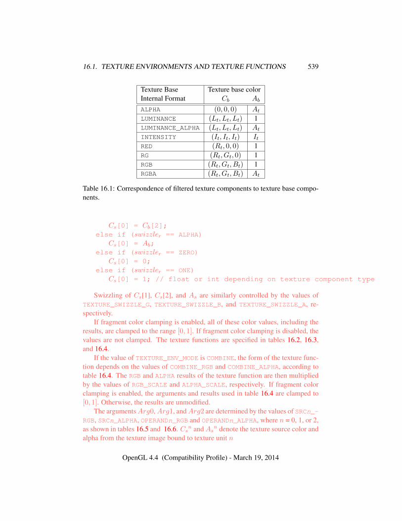
16.1. TEXTURE ENVIRONMENTS AND TEXTURE FUNCTIONS 539
Texture Base Texture base colorInternal Format Cb Ab
ALPHA (0, 0, 0) At
LUMINANCE (Lt, Lt, Lt) 1LUMINANCE_ALPHA (Lt, Lt, Lt) At
INTENSITY (It, It, It) ItRED (Rt, 0, 0) 1RG (Rt, Gt, 0) 1RGB (Rt, Gt, Bt) 1RGBA (Rt, Gt, Bt) At
Table 16.1: Correspondence of filtered texture components to texture base compo-nents.
Cs[0] = Cb[2];else if (swizzler == ALPHA)
Cs[0] = Ab;else if (swizzler == ZERO)
Cs[0] = 0;else if (swizzler == ONE)
Cs[0] = 1; // float or int depending on texture component type
Swizzling of Cs[1], Cs[2], and As are similarly controlled by the values ofTEXTURE_SWIZZLE_G, TEXTURE_SWIZZLE_B, and TEXTURE_SWIZZLE_A, re-spectively.
If fragment color clamping is enabled, all of these color values, including theresults, are clamped to the range [0, 1]. If fragment color clamping is disabled, thevalues are not clamped. The texture functions are specified in tables 16.2, 16.3,and 16.4.
If the value of TEXTURE_ENV_MODE is COMBINE, the form of the texture func-tion depends on the values of COMBINE_RGB and COMBINE_ALPHA, according totable 16.4. The RGB and ALPHA results of the texture function are then multipliedby the values of RGB_SCALE and ALPHA_SCALE, respectively. If fragment colorclamping is enabled, the arguments and results used in table 16.4 are clamped to[0, 1]. Otherwise, the results are unmodified.
The argumentsArg0,Arg1, andArg2 are determined by the values of SRCn_-RGB, SRCn_ALPHA, OPERANDn_RGB and OPERANDn_ALPHA, where n = 0, 1, or 2,as shown in tables 16.5 and 16.6. Cs
n andAsn denote the texture source color and
alpha from the texture image bound to texture unit n
OpenGL 4.4 (Compatibility Profile) - March 19, 2014
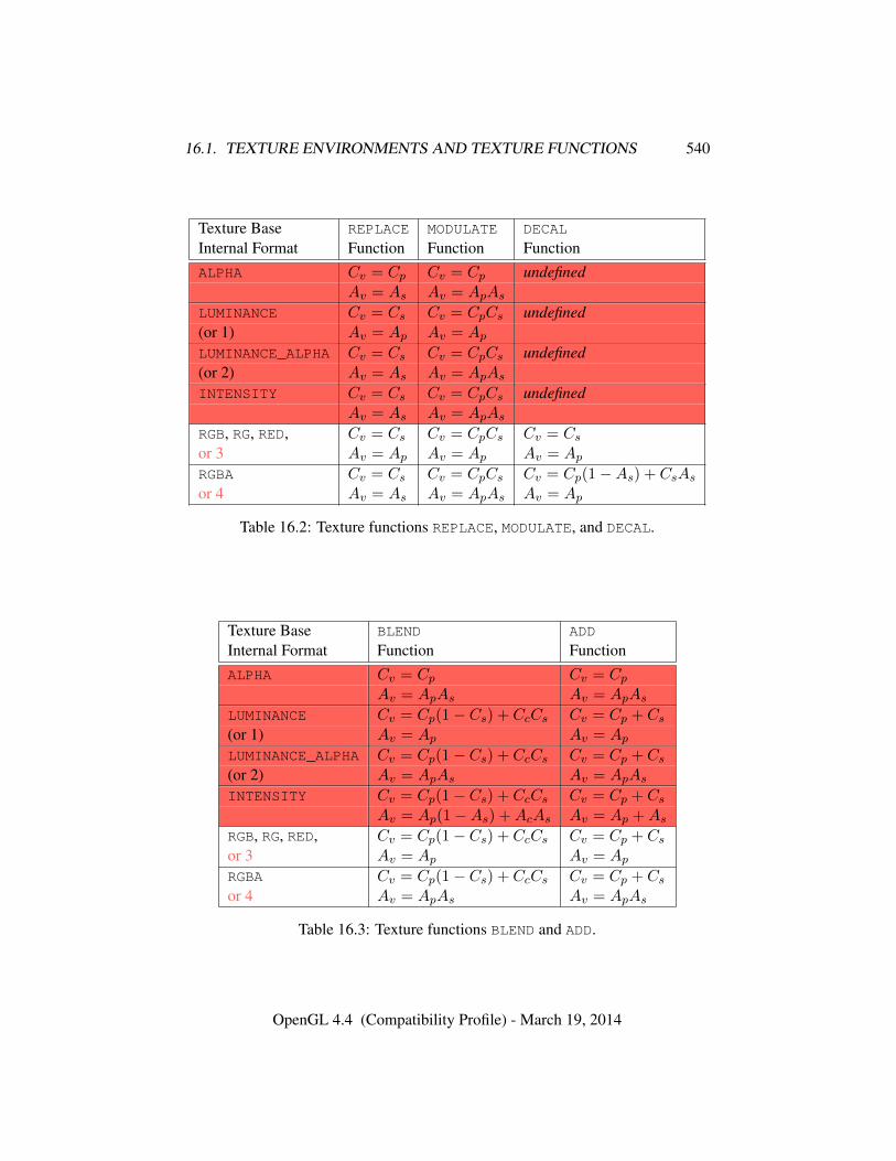
16.1. TEXTURE ENVIRONMENTS AND TEXTURE FUNCTIONS 540
Texture Base REPLACE MODULATE DECAL
Internal Format Function Function FunctionALPHA Cv = Cp Cv = Cp undefined
Av = As Av = ApAs
LUMINANCE Cv = Cs Cv = CpCs undefined(or 1) Av = Ap Av = Ap
LUMINANCE_ALPHA Cv = Cs Cv = CpCs undefined(or 2) Av = As Av = ApAs
INTENSITY Cv = Cs Cv = CpCs undefinedAv = As Av = ApAs
RGB, RG, RED, Cv = Cs Cv = CpCs Cv = Cs
or 3 Av = Ap Av = Ap Av = Ap
RGBA Cv = Cs Cv = CpCs Cv = Cp(1−As) + CsAs
or 4 Av = As Av = ApAs Av = Ap
Table 16.2: Texture functions REPLACE, MODULATE, and DECAL.
Texture Base BLEND ADD
Internal Format Function FunctionALPHA Cv = Cp Cv = Cp
Av = ApAs Av = ApAs
LUMINANCE Cv = Cp(1− Cs) + CcCs Cv = Cp + Cs
(or 1) Av = Ap Av = Ap
LUMINANCE_ALPHA Cv = Cp(1− Cs) + CcCs Cv = Cp + Cs
(or 2) Av = ApAs Av = ApAs
INTENSITY Cv = Cp(1− Cs) + CcCs Cv = Cp + Cs
Av = Ap(1−As) +AcAs Av = Ap +As
RGB, RG, RED, Cv = Cp(1− Cs) + CcCs Cv = Cp + Cs
or 3 Av = Ap Av = Ap
RGBA Cv = Cp(1− Cs) + CcCs Cv = Cp + Cs
or 4 Av = ApAs Av = ApAs
Table 16.3: Texture functions BLEND and ADD.
OpenGL 4.4 (Compatibility Profile) - March 19, 2014
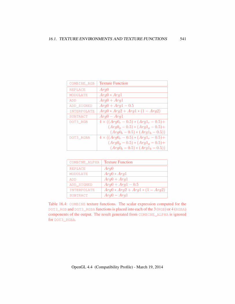
16.1. TEXTURE ENVIRONMENTS AND TEXTURE FUNCTIONS 541
COMBINE_RGB Texture FunctionREPLACE Arg0
MODULATE Arg0 ∗Arg1
ADD Arg0 +Arg1
ADD_SIGNED Arg0 +Arg1− 0.5
INTERPOLATE Arg0 ∗Arg2 +Arg1 ∗ (1−Arg2)
SUBTRACT Arg0−Arg1
DOT3_RGB 4× ((Arg0r − 0.5) ∗ (Arg1r − 0.5)+(Arg0g − 0.5) ∗ (Arg1g − 0.5)+(Arg0b − 0.5) ∗ (Arg1b − 0.5))
DOT3_RGBA 4× ((Arg0r − 0.5) ∗ (Arg1r − 0.5)+(Arg0g − 0.5) ∗ (Arg1g − 0.5)+(Arg0b − 0.5) ∗ (Arg1b − 0.5))
COMBINE_ALPHA Texture FunctionREPLACE Arg0
MODULATE Arg0 ∗Arg1
ADD Arg0 +Arg1
ADD_SIGNED Arg0 +Arg1− 0.5
INTERPOLATE Arg0 ∗Arg2 +Arg1 ∗ (1−Arg2)
SUBTRACT Arg0−Arg1
Table 16.4: COMBINE texture functions. The scalar expression computed for theDOT3_RGB and DOT3_RGBA functions is placed into each of the 3 (RGB) or 4 (RGBA)components of the output. The result generated from COMBINE_ALPHA is ignoredfor DOT3_RGBA.
OpenGL 4.4 (Compatibility Profile) - March 19, 2014
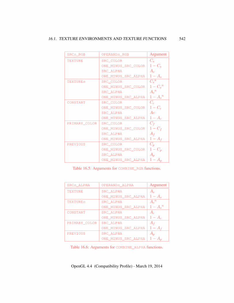
16.1. TEXTURE ENVIRONMENTS AND TEXTURE FUNCTIONS 542
SRCn_RGB OPERANDn_RGB ArgumentTEXTURE SRC_COLOR Cs
ONE_MINUS_SRC_COLOR 1− Cs
SRC_ALPHA As
ONE_MINUS_SRC_ALPHA 1−As
TEXTUREn SRC_COLOR Csn
ONE_MINUS_SRC_COLOR 1− Csn
SRC_ALPHA Asn
ONE_MINUS_SRC_ALPHA 1−Asn
CONSTANT SRC_COLOR Cc
ONE_MINUS_SRC_COLOR 1− Cc
SRC_ALPHA AcONE_MINUS_SRC_ALPHA 1−Ac
PRIMARY_COLOR SRC_COLOR Cf
ONE_MINUS_SRC_COLOR 1− Cf
SRC_ALPHA Af
ONE_MINUS_SRC_ALPHA 1−Af
PREVIOUS SRC_COLOR Cp
ONE_MINUS_SRC_COLOR 1− Cp
SRC_ALPHA Ap
ONE_MINUS_SRC_ALPHA 1−Ap
Table 16.5: Arguments for COMBINE_RGB functions.
SRCn_ALPHA OPERANDn_ALPHA ArgumentTEXTURE SRC_ALPHA As
ONE_MINUS_SRC_ALPHA 1−As
TEXTUREn SRC_ALPHA Asn
ONE_MINUS_SRC_ALPHA 1−Asn
CONSTANT SRC_ALPHA Ac
ONE_MINUS_SRC_ALPHA 1−Ac
PRIMARY_COLOR SRC_ALPHA Af
ONE_MINUS_SRC_ALPHA 1−Af
PREVIOUS SRC_ALPHA Ap
ONE_MINUS_SRC_ALPHA 1−Ap
Table 16.6: Arguments for COMBINE_ALPHA functions.
OpenGL 4.4 (Compatibility Profile) - March 19, 2014
16.2. TEXTURE APPLICATION 543
The state required for the current texture environment, for each texture unit,consists of a six-valued integer indicating the texture function, an eight-valued in-teger indicating the RGB combiner function and a six-valued integer indicating theALPHA combiner function, six four-valued integers indicating the combiner RGBand ALPHA source arguments, three four-valued integers indicating the combinerRGB operands, three two-valued integers indicating the combiner ALPHA operands,and four floating-point environment color values. In the initial state, the textureand combiner functions are each MODULATE, the combiner RGB and ALPHA sourcesare each TEXTURE, PREVIOUS, and CONSTANT for sources 0, 1, and 2 respectively,the combiner RGB operands for sources zero and one are each SRC_COLOR, thecombiner RGB operand for source 2, as well as for the combiner ALPHA operands,are each SRC_ALPHA, and the environment color is (0, 0, 0, 0).
The state required for the texture filtering parameters, for each texture unit,consists of a single floating-point level of detail bias. The initial value of the biasis 0.0.
16.1.1 Texture Environment Queries
The command
void GetTexEnv{if}v( enum env, enum pname, T *params );
returns information about pname for env in params. env must be either POINT_-SPRITE, TEXTURE_ENV, or TEXTURE_FILTER_CONTROL.
Errors
The same errors generated by TexEnv* for invalid env and pname param-eters are generated by GetTexEnv*.
16.2 Texture Application
Texturing is enabled or disabled using the generic Enable and Disable commands,respectively, with target TEXTURE_1D, TEXTURE_2D, TEXTURE_RECTANGLE,TEXTURE_3D, or TEXTURE_CUBE_MAP to enable the one-, two-, rectangular, three-dimensional, or cube map texture, respectively. If more than one of these texturesis enabled, the first one enabled from the following list is used:
• cube map texture
• three-dimensional texture
OpenGL 4.4 (Compatibility Profile) - March 19, 2014
16.2. TEXTURE APPLICATION 544
• rectangular texture
• two-dimensional texture
• one-dimensional texture
Array and multisample textures are only supported by shaders, and may notbe enabled for fixed-function texturing.
If all texturing is disabled, a rasterized fragment is passed on unaltered to thenext stage of the GL (although its texture coordinates may be discarded). Other-wise, a texture value is found according to the parameter values of the currentlybound texture image of the appropriate dimensionality using the rules given in sec-tions 8.13 through 8.15. This texture value is used along with the incoming frag-ment in computing the texture function indicated by the currently bound textureenvironment. The result of this function replaces the incoming fragment’s primaryR, G, B, and A values. These are the color values passed to subsequent operations.Other data associated with the incoming fragment remain unchanged, except thatthe texture coordinates may be discarded.
Note that the texture value may contain R, G, B, A, L, I , or D components,but it does not contain an S component. If the texture’s base internal format isDEPTH_STENCIL, for the purposes of texture application it is as if the base internalformat were DEPTH_COMPONENT.
Each texture unit is enabled and bound to texture objects independently fromthe other texture units. Each texture unit follows the precedence rules for one-,two-, three-dimensional, and cube map textures. Thus texture units can be per-forming texture mapping of different dimensionalities simultaneously. Each unithas its own enable and binding states.
Each texture unit is paired with an environment function, as shown in fig-ure 16.1. The second texture function is computed using the texture value fromthe second texture, the fragment resulting from the first texture function computa-tion and the second texture unit’s environment function. If there is a third texture,the fragment resulting from the second texture function is combined with the thirdtexture value using the third texture unit’s environment function and so on. The tex-ture unit selected by ActiveTexture determines which texture unit’s environmentis modified by TexEnv calls.
If the value of TEXTURE_ENV_MODE is COMBINE, the texture function associ-ated with a given texture unit is computed using the values specified by SRCn_RGB,SRCn_ALPHA, OPERANDn_RGB and OPERANDn_ALPHA. If TEXTUREn is specifiedas SRCn_RGB or SRCn_ALPHA, the texture value from texture unit n will be usedin computing the texture function for this texture unit.
OpenGL 4.4 (Compatibility Profile) - March 19, 2014
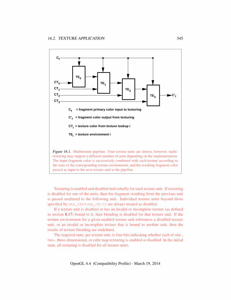
16.2. TEXTURE APPLICATION 545
TE0
TE1
TE2
TE3
CT0
CT1
CT2
CT3
C’f
CTi = texture color from texture lookup i
Cf = fragment primary color input to texturing
C’f = fragment color output from texturing
TEi = texture environment i
Cf
Figure 16.1. Multitexture pipeline. Four texture units are shown; however, multi-texturing may support a different number of units depending on the implementation.The input fragment color is successively combined with each texture according tothe state of the corresponding texture environment, and the resulting fragment colorpassed as input to the next texture unit in the pipeline.
Texturing is enabled and disabled individually for each texture unit. If texturingis disabled for one of the units, then the fragment resulting from the previous unitis passed unaltered to the following unit. Individual texture units beyond thosespecified by MAX_TEXTURE_UNITS are always treated as disabled.
If a texture unit is disabled or has an invalid or incomplete texture (as definedin section 8.17) bound to it, then blending is disabled for that texture unit. If thetexture environment for a given enabled texture unit references a disabled textureunit, or an invalid or incomplete texture that is bound to another unit, then theresults of texture blending are undefined.
The required state, per texture unit, is four bits indicating whether each of one-,two-, three-dimensional, or cube map texturing is enabled or disabled. In the initialstate, all texturing is disabled for all texture units.
OpenGL 4.4 (Compatibility Profile) - March 19, 2014
16.3. COLOR SUM 546
16.3 Color Sum
At the beginning of color sum, a fragment has two RGBA colors: a primary colorcpri (which texturing, if enabled, may have modified) and a secondary color csec.
If color sum is enabled, the R, G, and B components of these two colors aresummed to produce a single post-texturing RGBA color c. The A component of cis taken from the A component of cpri; the A component of csec is unused. If colorsum is disabled, then cpri is assigned to c. If fragment color clamping is enabled,the components of c are then clamped to the range [0, 1].
Color sum is enabled or disabled by calling Enable or Disable with targetCOLOR_SUM. If lighting is enabled and if a vertex shader is not active, the colorsum stage is always applied, ignoring the value of COLOR_SUM.
The state required is a single bit indicating whether color sum is enabled ordisabled. In the initial state, color sum is disabled.
Color sum has no effect in color index mode, or if a fragment shader is active.
16.4 Fog
If enabled, fog blends a fog color with a rasterized fragment’s post-texturing colorusing a blending factor f . Fog is enabled and disabled by calling Enable andDisable commands with target FOG.
This factor f is computed according to one of three equations:
f = exp(−d · c), (16.1)
f = exp(−(d · c)2), or (16.2)
f =e− ce− s
(16.3)
If a vertex or geometry shader is active, or if the fog source, as defined below, isFOG_COORD, then c is the interpolated value of the fog coordinate for this fragment.Otherwise, if the fog source is FRAGMENT_DEPTH, then c is the eye-coordinatedistance from the eye, (0, 0, 0, 1) in eye coordinates, to the fragment center. Theequation and the fog source, along with either d or e and s, is specified with
void Fog{if}( enum pname, T param );void Fog{if}v( enum pname, const T *params );
OpenGL 4.4 (Compatibility Profile) - March 19, 2014
16.4. FOG 547
If pname is FOG_MODE, then param must be, or params must point to an inte-ger that is one of the symbolic constants EXP, EXP2, or LINEAR, in which caseequation 16.1, 16.2, or 16.3, respectively, is selected for the fog calculation (if,when 16.3 is selected, e = s, results are undefined). If pname is FOG_COORD_SRC,then param must be, or params must point to an integer that is one of the symbolicconstants FRAGMENT_DEPTH or FOG_COORD. If pname is FOG_DENSITY, FOG_-START, or FOG_END, then param is or params points to a value that is d, s, or e,respectively.
Errors
An INVALID_VALUE error is generated if d is negative.
Data conversions are performed as specified in section 2.2.1.An implementation may choose to approximate the eye-coordinate distance
from the eye to each fragment center by |ze|.No matter which equation and approximation is used to compute f , the result
is clamped to [0, 1] to obtain the final f .f is used differently depending on whether the GL is in RGBA or color index
mode. In RGBA mode, if Cr represents a rasterized fragment’s R, G, or B value,then the corresponding value produced by fog is
C = fCr + (1− f)Cf .
(The rasterized fragment’s A value is not changed by fog blending.) The R, G, B,and A values of Cf are specified by calling Fog with pname equal to FOG_COLOR;in this case params points to four values comprising Cf . If these are not floating-point values, then they are converted to floating-point as described in equation 2.2.If fragment color clamping is enabled, the components of Cr and Cf and the resultC are clamped to the range [0, 1] before the fog blend is performed.
In color index mode, the formula for fog blending is
I = ir + (1− f)if
where ir is the rasterized fragment’s color index and if is a single-precisionfloating-point value. (1 − f)if is rounded to the nearest fixed-point value withthe same number of bits to the right of the binary point as ir, and the integer por-tion of I is masked (bitwise ANDed) with 2n− 1, where n is the number of bits ina color in the color index buffer (buffers are discussed in chapter 9). The value ofif is set by calling Fog with pname set to FOG_INDEX and param being or paramspointing to a single value for the fog index. The integer part of if is masked with2n − 1.
OpenGL 4.4 (Compatibility Profile) - March 19, 2014
16.4. FOG 548
The state required for fog consists of a three valued integer to select the fogequation, three floating-point values d, e, and s, an RGBA fog color and a fogcolor index, a two-valued integer to select the fog coordinate source, and a singlebit to indicate whether or not fog is enabled. In the initial state, fog is disabled,FOG_COORD_SRC is FRAGMENT_DEPTH, FOG_MODE is EXP, d = 1.0, e = 1.0, ands = 0.0; Cf = (0, 0, 0, 0) and if = 0.
Fog has no effect if a fragment shader is active.
OpenGL 4.4 (Compatibility Profile) - March 19, 2014
Chapter 17
Writing Fragments and Samplesto the Framebuffer
After programmable or fixed-function fragment processing, the following fixed-function operations are applied to the resulting fragments:
• Antialiasing application (see section 17.1).
• Multisample point fade (see section 17.2).
• Per-fragment operations and writing to the framebuffer (see section 17.3).
Writing to the framebuffer is the final set of operations performed as a result ofdrawing primitives.
Additional commands controlling the framebuffer as a whole are described insection 17.4.
17.1 Antialiasing Application
If antialiasing is enabled for the primitive from which a rasterized fragment wasproduced, then the computed coverage value is applied to the fragment. In RGBAmode, the value is multiplied by the fragment’s alpha value to yield a final alphavalue. In color index mode, the value is used to set the low order bits of the colorindex value as described in section 14.3. The coverage value is applied separatelyto each fragment color, and only applied if the corresponding color buffer in theframebuffer has a fixed- or floating-point format.
549
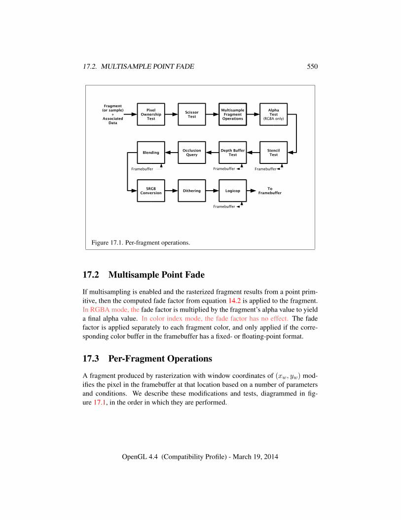
17.2. MULTISAMPLE POINT FADE 550
Depth BufferTest
ToFramebuffer
PixelOwnership
Test
ScissorTest
Logicop
Fragment(or sample)
+Associated
Data
StencilTest
SRGBConversion
Dithering
MultisampleFragment
Operations
Framebuffer Framebuffer
AlphaTest
(RGBA only)
OcclusionQuery
Blending
Framebuffer
Framebuffer
Figure 17.1. Per-fragment operations.
17.2 Multisample Point Fade
If multisampling is enabled and the rasterized fragment results from a point prim-itive, then the computed fade factor from equation 14.2 is applied to the fragment.In RGBA mode, the fade factor is multiplied by the fragment’s alpha value to yielda final alpha value. In color index mode, the fade factor has no effect. The fadefactor is applied separately to each fragment color, and only applied if the corre-sponding color buffer in the framebuffer has a fixed- or floating-point format.
17.3 Per-Fragment Operations
A fragment produced by rasterization with window coordinates of (xw, yw) mod-ifies the pixel in the framebuffer at that location based on a number of parametersand conditions. We describe these modifications and tests, diagrammed in fig-ure 17.1, in the order in which they are performed.
OpenGL 4.4 (Compatibility Profile) - March 19, 2014
17.3. PER-FRAGMENT OPERATIONS 551
17.3.1 Pixel Ownership Test
The first test is to determine if the pixel at location (xw, yw) in the framebufferis currently owned by the GL (more precisely, by this GL context). If it is not,the window system decides the fate of the incoming fragment. Possible results arethat the fragment is discarded or that some subset of the subsequent per-fragmentoperations are applied to the fragment. This test allows the window system tocontrol the GL’s behavior, for instance, when a GL window is obscured.
If the draw framebuffer is a framebuffer object (see section 17.4.1), the pixelownership test always passes, since the pixels of framebuffer objects are owned bythe GL, not the window system. If the draw framebuffer is the default framebuffer,the window system controls pixel ownership.
17.3.2 Scissor Test
The scissor test determines if (xw, yw) lies within the scissor rectangle defined byfour values for each viewport. These values are set with
void ScissorArrayv( uint first, sizei count, constint *v );
void ScissorIndexed( uint index, int left, int bottom,sizei width, sizei height );
void ScissorIndexedv( uint index, int *v );void Scissor( int left, int bottom, sizei width,
sizei height );
ScissorArrayv defines a set of scissor rectangles that are each applied to thecorresponding viewport (see section 13.6.1). first specifies the index of the firstscissor rectangle to modify, and count specifies the number of scissor rectangles. vcontains the address of an array of integers containing the left, bottom, width andheight of the scissor rectangles, in that order.
If left ≤ xw < left + width and bottom ≤ yw < bottom + height for theselected scissor rectangle, then the scissor test passes. Otherwise, the test fails andthe fragment is discarded. For points, lines, and polygons, the scissor rectanglefor a primitive is selected in the same manner as the viewport (see section 13.6.1).For bitmaps, buffer clears (see section 17.4.3), and pixel rectangles, the scissorrectangle numbered zero is used for the scissor test.
Errors
An INVALID_VALUE error is generated by ScissorArrayv if first +count
OpenGL 4.4 (Compatibility Profile) - March 19, 2014
17.3. PER-FRAGMENT OPERATIONS 552
is greater than the value of MAX_VIEWPORTS.An INVALID_VALUE error is generated if width or height is negative.
The scissor test is enabled or disabled for all viewports using Enable or Dis-able with target SCISSOR_TEST. The test is enabled or disabled for a specificviewport using Enablei or Disablei with the constant SCISSOR_TEST and the in-dex of the selected viewport. When disabled, it is as if the scissor test alwayspasses. The value of the scissor test enable for viewport i can be queried by callingIsEnabledi with target SCISSOR_TEST and index i. The value of the scissor testenable for viewport zero may also be queried by calling IsEnabled with the samesymbolic constant, but no index parameter.
Errors
An INVALID_VALUE error is generated by Enablei, Disablei and IsEn-abledi if target is SCISSOR_TEST and index is greater than or equal to thevalue of MAX_VIEWPORTS.
The state required consists of four integer values per viewport, and a bit in-dicating whether the test is enabled or disabled for each viewport. In the initialstate, left = bottom = 0, and width and height are determined by the size of thewindow into which the GL is to do its rendering for all viewports. If the defaultframebuffer is bound but no default framebuffer is associated with the GL context(see chapter 9), then width and height are initially set to zero. Initially, the scissortest is disabled for all viewports.
ScissorIndexed and ScissorIndexedv specify the scissor rectangle for a singleviewport and are equivalent (assuming no errors are generated) to:
int v[] = { left, bottom, width, height };ScissorArrayv(index, 1, v);
and
ScissorArrayv(index, 1, v);
respectively.Scissor sets the scissor rectangle for all viewports to the same values and is
equivalent (assuming no errors are generated) to:
for (uint i = 0; i < MAX_VIEWPORTS; i++) {ScissorIndexed(i, left, bottom, width, height);
}
OpenGL 4.4 (Compatibility Profile) - March 19, 2014
17.3. PER-FRAGMENT OPERATIONS 553
Calling Enable or Disable with target SCISSOR_TEST is equivalent, assumingno errors, to:
for (uint i = 0; i < MAX_VIEWPORTS; i++) {Enablei(SCISSOR_TEST, i);/* or */Disablei(SCISSOR_TEST, i);
}
17.3.3 Multisample Fragment Operations
This step modifies fragment alpha and coverage values based on the valuesof SAMPLE_ALPHA_TO_COVERAGE, SAMPLE_ALPHA_TO_ONE, SAMPLE_-
COVERAGE, SAMPLE_COVERAGE_VALUE, SAMPLE_COVERAGE_INVERT,SAMPLE_MASK, SAMPLE_MASK_VALUE, and an output sample mask option-ally written by the fragment shader. No changes to the fragment alpha or coveragevalues are made at this step if MULTISAMPLE is disabled, or if the value ofSAMPLE_BUFFERS is not one.
All alpha values in this section refer only to the alpha component of the frag-ment shader output linked to color number zero, index zero (see section 15.2.3) ifa fragment shader is in use, or the alpha component of the result of fixed-functionfragment shading. If the fragment shader does not write to this output, the alphavalue is undefined.
SAMPLE_ALPHA_TO_COVERAGE, SAMPLE_ALPHA_TO_ONE, SAMPLE_-
COVERAGE, and SAMPLE_MASK are enabled and disabled by calling Enable andDisable with the desired token value. All four values are queried by calling IsEn-abled with the desired token value. If draw buffer zero references a buffer with aninteger format, the SAMPLE_ALPHA_TO_COVERAGE and SAMPLE_ALPHA_TO_ONEoperations are skipped.
If SAMPLE_ALPHA_TO_COVERAGE is enabled, a temporary coverage value isgenerated where each bit is determined by the alpha value at the correspondingsample location. The temporary coverage value is then ANDed with the fragmentcoverage value to generate a new fragment coverage value. If the fragment shaderoutputs an integer to color number zero, index zero when not rendering to an integerformat, the coverage value is undefined.
No specific algorithm is required for converting the sample alpha values to atemporary coverage value. It is intended that the number of 1’s in the temporarycoverage be proportional to the set of alpha values for the fragment, with all 1’scorresponding to the maximum of all alpha values, and all 0’s corresponding toall alpha values being 0. The alpha values used to generate a coverage value are
OpenGL 4.4 (Compatibility Profile) - March 19, 2014
17.3. PER-FRAGMENT OPERATIONS 554
clamped to the range [0, 1]. It is also intended that the algorithm be pseudo-randomin nature, to avoid image artifacts due to regular coverage sample locations. Thealgorithm can and probably should be different at different pixel locations. If itdoes differ, it should be defined relative to window, not screen, coordinates, so thatrendering results are invariant with respect to window position.
Next, if SAMPLE_ALPHA_TO_ONE is enabled, each alpha value is replaced bythe maximum representable alpha value for fixed-point color buffers, or by 1.0 forfloating-point buffers. Otherwise, the alpha values are not changed.
Next, if a fragment shader is active and statically assigns to the built-in outputvariable gl_SampleMask, the fragment coverage is ANDed with the bits of thesample mask. If such a fragment shader did not assign a value to gl_SampleMaskdue to flow control, the value ANDed with the fragment coverage is undefined. Ifno fragment shader is active, or if the active fragment shader does not staticallyassign values to gl_SampleMask, the fragment coverage is not modified.
Next, if SAMPLE_COVERAGE is enabled, the fragment coverage is ANDed withanother temporary coverage. This temporary coverage is generated in the samemanner as the one described above, but as a function of the value of SAMPLE_-COVERAGE_VALUE. The function need not be identical, but it must have the sameproperties of proportionality and invariance. If SAMPLE_COVERAGE_INVERT isTRUE, the temporary coverage is inverted (all bit values are inverted) before it isANDed with the fragment coverage.
The values of SAMPLE_COVERAGE_VALUE and SAMPLE_COVERAGE_INVERT
are specified by calling
void SampleCoverage( float value, boolean invert );
with value set to the desired coverage value, and invert set to TRUE or FALSE.value is clamped to [0, 1] before being stored as SAMPLE_COVERAGE_VALUE.SAMPLE_COVERAGE_VALUE is queried by calling GetFloatv with pname set toSAMPLE_COVERAGE_VALUE. SAMPLE_COVERAGE_INVERT is queried by callingGetBooleanv with pname set to SAMPLE_COVERAGE_INVERT.
Finally, if SAMPLE_MASK is enabled, the fragment coverage is ANDed withthe coverage value SAMPLE_MASK_VALUE. The value of SAMPLE_MASK_VALUE isspecified using
void SampleMaski( uint maskNumber, bitfield mask );
with mask set to the desired mask for mask word maskNumber. SAMPLE_MASK_-VALUE is queried by calling GetIntegeri v with target set to SAMPLE_MASK_-
VALUE and the index set to maskNumber. Bit B of mask word M corresponds tosample 32×M +B as described in section 14.3.1.
OpenGL 4.4 (Compatibility Profile) - March 19, 2014
17.3. PER-FRAGMENT OPERATIONS 555
Errors
An INVALID_VALUE error is generated if maskNumber is greater than orequal to the value of MAX_SAMPLE_MASK_WORDS.
17.3.4 Alpha Test
The alpha test discards a fragment conditional on the outcome of a comparisonbetween the incoming fragment’s alpha value and a constant value. In color indexmode, or if draw buffer zero references a buffer with an integer format, this step isskipped.
The alpha value in this section refers only to the alpha component of the frag-ment shader output linked to color number zero, index zero (see section 15.2.3) ifa fragment shader is in use, or the alpha component of the result of fixed-functionfragment shading. If the fragment shader does not write to this output, the alphavalue is undefined.
The comparison is enabled or disabled with the generic Enable and Disablecommands using target ALPHA_TEST. When disabled, it is as if the comparisonalways passes. The test is controlled with
void AlphaFunc( enum func, float ref );
func is a symbolic constant indicating the alpha test function; ref is a referencevalue clamped to the range [0, 1]. When performing the alpha test, the GL willconvert the reference value to the same representation as the fragment’s alpha value(floating-point or fixed-point). For fixed-point, the reference value is convertedaccording to equation 2.3 using the bit-width rule for an A component describedin section 2.3.4, If draw buffer zero does not reference a buffer, the reference valueis converted as if it were fixed-point with at least 8 bits of A. The fragment’s alphavalue is rounded to the nearest integer.
The possible constants specifying the test function are NEVER, ALWAYS, LESS,LEQUAL, EQUAL, GEQUAL, GREATER, or NOTEQUAL, meaning pass the fragmentnever, always, if the fragment’s alpha value is less than, less than or equal to,equal to, greater than or equal to, greater than, or not equal to the reference value,respectively.
The required state consists of the floating-point reference value, an eight-valued integer indicating the comparison function, and a bit indicating if the com-parison is enabled or disabled. The initial state is for the reference value to be 0.0and the function to be ALWAYS. Initially, the alpha test is disabled.
OpenGL 4.4 (Compatibility Profile) - March 19, 2014
17.3. PER-FRAGMENT OPERATIONS 556
17.3.5 Stencil Test
The stencil test conditionally discards a fragment based on the outcome of a com-parison between the value in the stencil buffer at location (xw, yw) and a referencevalue. The test is enabled or disabled with the Enable and Disable commands,using target STENCIL_TEST. When disabled, the stencil test and associated modi-fications are not made, and the fragment is always passed.
The stencil test is controlled with
void StencilFunc( enum func, int ref, uint mask );void StencilFuncSeparate( enum face, enum func, int ref,
uint mask );void StencilOp( enum sfail, enum dpfail, enum dppass );void StencilOpSeparate( enum face, enum sfail, enum dpfail,
enum dppass );
There are two sets of stencil-related state, the front stencil state set and the backstencil state set. Stencil tests and writes use the front set of stencil state when pro-cessing fragments rasterized from non-polygon primitives (points, lines, bitmaps,and image rectangles) and front-facing polygon primitives while the back set ofstencil state is used when processing fragments rasterized from back-facing poly-gon primitives. For the purposes of stencil testing, a primitive is still considered apolygon even if the polygon is to be rasterized as points or lines due to the currentpolygon mode. Whether a polygon is front- or back-facing is determined in thesame manner used for two-sided lighting (see section 12.2.1) and
StencilFuncSeparate and StencilOpSeparate take a face argument which canbe FRONT, BACK, or FRONT_AND_BACK and indicates which set of state is affected.StencilFunc and StencilOp set front and back stencil state to identical values.
StencilFunc and StencilFuncSeparate take three arguments that controlwhether the stencil test passes or fails. ref is an integer reference value that is usedin the unsigned stencil comparison. Stencil comparison operations and queries ofref clamp its value to the range [0, 2s − 1], where s is the number of bits in thestencil buffer attached to the draw framebuffer. The s least significant bits of maskare bitwise ANDed with both the reference and the stored stencil value, and theresulting masked values are those that participate in the comparison controlled byfunc. func is a symbolic constant that determines the stencil comparison function;the eight symbolic constants are NEVER, ALWAYS, LESS, LEQUAL, EQUAL, GEQUAL,GREATER, or NOTEQUAL. Accordingly, the stencil test passes never, always, and ifthe masked reference value is less than, less than or equal to, equal to, greater thanor equal to, greater than, or not equal to the masked stored value in the stencilbuffer.
OpenGL 4.4 (Compatibility Profile) - March 19, 2014
17.3. PER-FRAGMENT OPERATIONS 557
StencilOp and StencilOpSeparate take three arguments that indicate whathappens to the stored stencil value if this or certain subsequent tests fail or pass.sfail indicates what action is taken if the stencil test fails. The symbolic constantsare KEEP, ZERO, REPLACE, INCR, DECR, INVERT, INCR_WRAP, and DECR_WRAP.These correspond to keeping the current value, setting to zero, replacing with thereference value, incrementing with saturation, decrementing with saturation, bit-wise inverting it, incrementing without saturation, and decrementing without satu-ration.
For purposes of increment and decrement, the stencil bits are considered as anunsigned integer. Incrementing or decrementing with saturation clamps the stencilvalue at 0 and the maximum representable value. Incrementing or decrementingwithout saturation will wrap such that incrementing the maximum representablevalue results in 0, and decrementing 0 results in the maximum representable value.
The same symbolic values are given to indicate the stencil action if the depthbuffer test (see section 17.3.6) fails (dpfail), or if it passes (dppass).
If the stencil test fails, the incoming fragment is discarded. The state requiredconsists of the most recent values passed to StencilFunc or StencilFuncSeparateand to StencilOp or StencilOpSeparate, and a bit indicating whether stencil test-ing is enabled or disabled. In the initial state, stenciling is disabled, the front andback stencil reference value are both zero, the front and back stencil comparisonfunctions are both ALWAYS, and the front and back stencil mask are both set to thevalue 2s − 1, where s is greater than or equal to the number of bits in the deepeststencil buffer supported by the GL implementation. Initially, all three front andback stencil operations are KEEP.
If there is no stencil buffer, no stencil modification can occur, and it is as if thestencil tests always pass, regardless of any calls to StencilFunc.
17.3.6 Depth Buffer Test
The depth buffer test discards the incoming fragment if a depth comparison fails.The comparison is enabled or disabled with the generic Enable and Disable com-mands using target DEPTH_TEST. When disabled, the depth comparison and sub-sequent possible updates to the depth buffer value are bypassed and the fragment ispassed to the next operation. The stencil value, however, is modified as indicatedbelow as if the depth buffer test passed. If enabled, the comparison takes place andthe depth buffer and stencil value may subsequently be modified.
The comparison is specified with
void DepthFunc( enum func );
OpenGL 4.4 (Compatibility Profile) - March 19, 2014
17.3. PER-FRAGMENT OPERATIONS 558
This command takes a single symbolic constant: one of NEVER, ALWAYS, LESS,LEQUAL, EQUAL, GREATER, GEQUAL, NOTEQUAL. Accordingly, the depth buffertest passes never, always, if the incoming fragment’s zw value is less than, lessthan or equal to, equal to, greater than, greater than or equal to, or not equal tothe depth value stored at the location given by the incoming fragment’s (xw, yw)coordinates.
If depth clamping (see section 13.5) is enabled, before the incoming fragment’szw is compared zw is clamped to the range [min(n, f),max(n, f)], where n and fare the current near and far depth range values (see section 13.6.1)
If the depth buffer test fails, the incoming fragment is discarded. The stencilvalue at the fragment’s (xw, yw) coordinates is updated according to the functioncurrently in effect for depth buffer test failure. Otherwise, the fragment continuesto the next operation and the value of the depth buffer at the fragment’s (xw, yw)location is set to the fragment’s zw value. In this case the stencil value is updatedaccording to the function currently in effect for depth buffer test success.
The necessary state is an eight-valued integer and a single bit indicatingwhether depth buffering is enabled or disabled. In the initial state the functionis LESS and the test is disabled.
If there is no depth buffer, it is as if the depth buffer test always passes.
17.3.7 Occlusion Queries
Occlusion queries use query objects to track the number of fragments or samplesthat pass the depth test. An occlusion query can be started and finished by callingBeginQuery and EndQuery, respectively, with a target of SAMPLES_PASSED,ANY_SAMPLES_PASSED, or ANY_SAMPLES_PASSED_CONSERVATIVE.
When an occlusion query is started with target SAMPLES_PASSED, thesamples-passed count maintained by the GL is set to zero. When an occlusionquery is active, the samples-passed count is incremented for each fragment thatpasses the depth test. If the value of SAMPLE_BUFFERS is zero, then the samples-passed count is incremented by one for each fragment. If the value of SAMPLE_-BUFFERS is one, then the samples-passed count is incremented by the number ofsamples whose coverage bit is set. However, implementations, at their discretion,may instead increase the samples-passed count by the value of SAMPLES if anysample in the fragment is covered.
When an occlusion query finishes and all fragments generated by commandsissued prior to EndQuery have been generated, the samples-passed count is writtento the corresponding query object as the query result value, and the query result forthat object is marked as available.
When an occlusion query is started with the target ANY_SAMPLES_PASSED,
OpenGL 4.4 (Compatibility Profile) - March 19, 2014
17.3. PER-FRAGMENT OPERATIONS 559
the samples-boolean state maintained by the GL is set to FALSE. While that oc-clusion query is active, the samples-boolean state is set to TRUE if any fragmentor sample passes the depth test. When the target is ANY_SAMPLES_PASSED_-
CONSERVATIVE, an implementation may choose to use a less precise version ofthe test which can additionally set the samples-boolean state to TRUE in some otherimplementation-dependent cases. This may offer better performance on some im-plementations at the expense of false positives. When the occlusion query finishes,the samples-boolean state of FALSE or TRUE is written to the corresponding queryobject as the query result value, and the query result for that object is marked asavailable.
17.3.8 Blending
Blending combines the incoming source fragment’s R, G, B, and A values withthe destination R, G, B, and A values stored in the framebuffer at the fragment’s(xw, yw) location.
Source and destination values are combined according to the blend equation,quadruplets of source and destination weighting factors determined by the blendfunctions, and a constant blend color to obtain a new set of R, G, B, and A values,as described below.
If the color buffer is fixed-point, the components of the source and destinationvalues and blend factors are each clamped to [0, 1] or [−1, 1] respectively for an un-signed normalized or signed normalized color buffer prior to evaluating the blendequation. If the color buffer is floating-point, no clamping occurs. The resultingfour values are sent to the next operation.
Blending applies only in RGBA mode; and only if the color buffer has a fixed-point or floating-point format. In color index mode, or if the color buffer has aninteger format, proceed to the next operation.
Blending is enabled or disabled for an individual draw buffer with the com-mands
void Enablei( enum target, uint index );void Disablei( enum target, uint index );
target is the symbolic constant BLEND and index is an integer i specifying the drawbuffer associated with the symbolic constant DRAW_BUFFERi. If the color bufferassociated with DRAW_BUFFERi is one of FRONT, BACK, LEFT, RIGHT, or FRONT_-AND_BACK (specifying multiple color buffers), then the state enabled or disabled isapplicable for all of the buffers. Blending can be enabled or disabled for all drawbuffers using Enable or Disable with the symbolic constant BLEND. If blending
OpenGL 4.4 (Compatibility Profile) - March 19, 2014
17.3. PER-FRAGMENT OPERATIONS 560
is disabled for a particular draw buffer, or if logical operation on color values isenabled (section 17.3.11), proceed to the next operation.
If multiple fragment colors are being written to multiple buffers (see sec-tion 17.4.1), blending is computed and applied separately for each fragment colorand the corresponding buffer.
Errors
An INVALID_VALUE error is generated by Enablei, Disablei and IsEn-abledi if target is BLEND and index is greater than or equal to the value ofMAX_DRAW_BUFFERS.
17.3.8.1 Blend Equation
Blending is controlled by the blend equation. This equation can be simultaneouslyset to the same value for all draw buffers using the commands
void BlendEquation( enum mode );void BlendEquationSeparate( enum modeRGB,
enum modeAlpha );
or for an individual draw buffer using the indexed commands
void BlendEquationi( uint buf, enum mode );void BlendEquationSeparatei( uint buf, enum modeRGB,
enum modeAlpha );
BlendEquationSeparate and BlendEquationSeparatei argument modeRGBdetermines the RGB blend equation while modeAlpha determines the alpha blendequation. BlendEquation and BlendEquationi argument mode determines boththe RGB and alpha blend equations. mode, modeRGB, and modeAlpha must beone of the blend equation modes in table 17.1. BlendEquation and BlendEqua-tionSeparate modify the blend equations for all draw buffers. BlendEquationiand BlendEquationSeparatei modify the blend equations associated with an in-dividual draw buffer. The buf argument is an integer i that indicates that the blendequations should be modified for DRAW_BUFFERi.
Errors
An INVALID_VALUE error is generated if buf is not in the range zero tothe value of MAX_DRAW_BUFFERS minus one.
An INVALID_ENUM error is generated if any of mode, modeRGB, or mod-
OpenGL 4.4 (Compatibility Profile) - March 19, 2014

17.3. PER-FRAGMENT OPERATIONS 561
eAlpha are not one of the blend equation modes in table 17.1.
Signed or unsigned normalized fixed-point destination (framebuffer) com-ponents are represented as described in section 2.3.4. Constant color compo-nents, floating-point destination components, and source (fragment) componentsare taken to be floating-point values. If source components are represented in-ternally by the GL as fixed-point values, they are also interpreted according tosection 2.3.4.
Prior to blending, signed and unsigned normalized fixed-point color compo-nents undergo an implied conversion to floating-point using equations 2.2 and 2.1,respectively. This conversion must leave the values zero and one invariant. Blend-ing computations are treated as if carried out in floating-point, and will be per-formed with a precision and dynamic range no lower than that used to representdestination components.
If FRAMEBUFFER_SRGB is enabled and the value of FRAMEBUFFER_-
ATTACHMENT_COLOR_ENCODING for the framebuffer attachment correspondingto the destination buffer is SRGB (see section 9.2.3), the R, G, and B destinationcolor values (after conversion from fixed-point to floating-point) are considered tobe encoded for the sRGB color space and hence must be linearized prior to theiruse in blending. Each R, G, and B component is converted in the same fashiondescribed for sRGB texture components in section 8.24.
If FRAMEBUFFER_SRGB is disabled or the value of FRAMEBUFFER_-
ATTACHMENT_COLOR_ENCODING is not SRGB, no linearization is performed.The resulting linearized R, G, and B and unmodified A values are recombined
as the destination color used in blending computations.Table 17.1 provides the corresponding per-component blend equations for each
mode, whether acting on RGB components for modeRGB or the alpha componentfor modeAlpha.
In the table, the s subscript on a color component abbreviation (R, G, B, orA) refers to the source color component for an incoming fragment, the d subscripton a color component abbreviation refers to the destination color component atthe corresponding framebuffer location, and the c subscript on a color componentabbreviation refers to the constant blend color component. A color component ab-breviation without a subscript refers to the new color component resulting fromblending. Additionally, Sr, Sg, Sb, and Sa are the red, green, blue, and alpha com-ponents of the source weighting factors determined by the source blend function,and Dr, Dg, Db, and Da are the red, green, blue, and alpha components of thedestination weighting factors determined by the destination blend function. Blendfunctions are described below.
OpenGL 4.4 (Compatibility Profile) - March 19, 2014
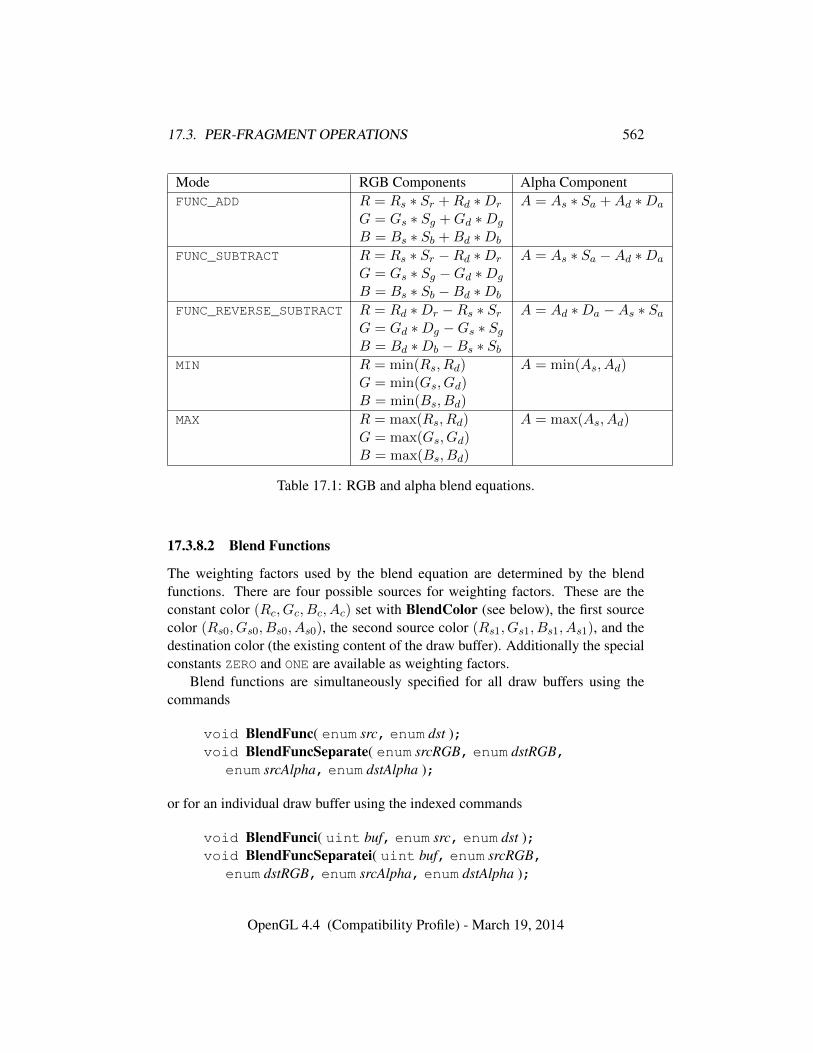
17.3. PER-FRAGMENT OPERATIONS 562
Mode RGB Components Alpha ComponentFUNC_ADD R = Rs ∗ Sr +Rd ∗Dr A = As ∗ Sa +Ad ∗Da
G = Gs ∗ Sg +Gd ∗Dg
B = Bs ∗ Sb +Bd ∗Db
FUNC_SUBTRACT R = Rs ∗ Sr −Rd ∗Dr A = As ∗ Sa −Ad ∗Da
G = Gs ∗ Sg −Gd ∗Dg
B = Bs ∗ Sb −Bd ∗Db
FUNC_REVERSE_SUBTRACT R = Rd ∗Dr −Rs ∗ Sr A = Ad ∗Da −As ∗ SaG = Gd ∗Dg −Gs ∗ SgB = Bd ∗Db −Bs ∗ Sb
MIN R = min(Rs, Rd) A = min(As, Ad)G = min(Gs, Gd)B = min(Bs, Bd)
MAX R = max(Rs, Rd) A = max(As, Ad)G = max(Gs, Gd)B = max(Bs, Bd)
Table 17.1: RGB and alpha blend equations.
17.3.8.2 Blend Functions
The weighting factors used by the blend equation are determined by the blendfunctions. There are four possible sources for weighting factors. These are theconstant color (Rc, Gc, Bc, Ac) set with BlendColor (see below), the first sourcecolor (Rs0, Gs0, Bs0, As0), the second source color (Rs1, Gs1, Bs1, As1), and thedestination color (the existing content of the draw buffer). Additionally the specialconstants ZERO and ONE are available as weighting factors.
Blend functions are simultaneously specified for all draw buffers using thecommands
void BlendFunc( enum src, enum dst );void BlendFuncSeparate( enum srcRGB, enum dstRGB,
enum srcAlpha, enum dstAlpha );
or for an individual draw buffer using the indexed commands
void BlendFunci( uint buf, enum src, enum dst );void BlendFuncSeparatei( uint buf, enum srcRGB,
enum dstRGB, enum srcAlpha, enum dstAlpha );
OpenGL 4.4 (Compatibility Profile) - March 19, 2014
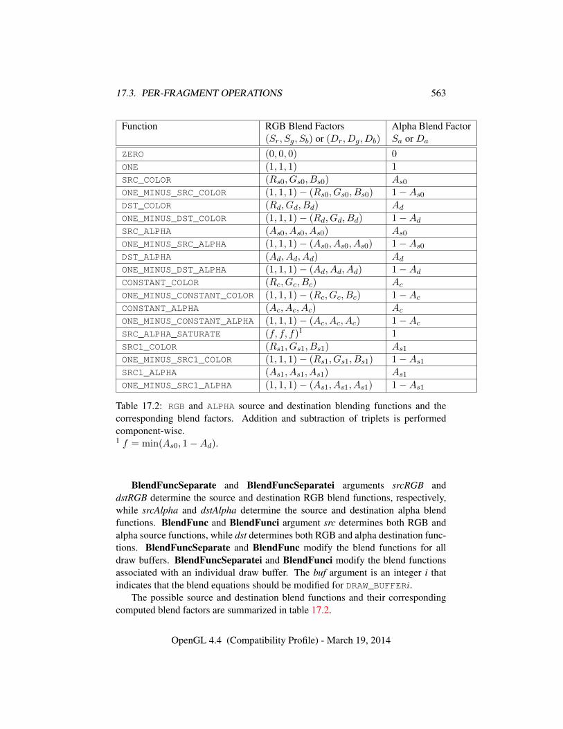
17.3. PER-FRAGMENT OPERATIONS 563
Function RGB Blend Factors Alpha Blend Factor(Sr, Sg, Sb) or (Dr, Dg, Db) Sa or Da
ZERO (0, 0, 0) 0
ONE (1, 1, 1) 1
SRC_COLOR (Rs0, Gs0, Bs0) As0
ONE_MINUS_SRC_COLOR (1, 1, 1)− (Rs0, Gs0, Bs0) 1−As0
DST_COLOR (Rd, Gd, Bd) Ad
ONE_MINUS_DST_COLOR (1, 1, 1)− (Rd, Gd, Bd) 1−Ad
SRC_ALPHA (As0, As0, As0) As0
ONE_MINUS_SRC_ALPHA (1, 1, 1)− (As0, As0, As0) 1−As0
DST_ALPHA (Ad, Ad, Ad) Ad
ONE_MINUS_DST_ALPHA (1, 1, 1)− (Ad, Ad, Ad) 1−Ad
CONSTANT_COLOR (Rc, Gc, Bc) Ac
ONE_MINUS_CONSTANT_COLOR (1, 1, 1)− (Rc, Gc, Bc) 1−Ac
CONSTANT_ALPHA (Ac, Ac, Ac) Ac
ONE_MINUS_CONSTANT_ALPHA (1, 1, 1)− (Ac, Ac, Ac) 1−Ac
SRC_ALPHA_SATURATE (f, f, f)1 1
SRC1_COLOR (Rs1, Gs1, Bs1) As1
ONE_MINUS_SRC1_COLOR (1, 1, 1)− (Rs1, Gs1, Bs1) 1−As1
SRC1_ALPHA (As1, As1, As1) As1
ONE_MINUS_SRC1_ALPHA (1, 1, 1)− (As1, As1, As1) 1−As1
Table 17.2: RGB and ALPHA source and destination blending functions and thecorresponding blend factors. Addition and subtraction of triplets is performedcomponent-wise.1 f = min(As0, 1−Ad).
BlendFuncSeparate and BlendFuncSeparatei arguments srcRGB anddstRGB determine the source and destination RGB blend functions, respectively,while srcAlpha and dstAlpha determine the source and destination alpha blendfunctions. BlendFunc and BlendFunci argument src determines both RGB andalpha source functions, while dst determines both RGB and alpha destination func-tions. BlendFuncSeparate and BlendFunc modify the blend functions for alldraw buffers. BlendFuncSeparatei and BlendFunci modify the blend functionsassociated with an individual draw buffer. The buf argument is an integer i thatindicates that the blend equations should be modified for DRAW_BUFFERi.
The possible source and destination blend functions and their correspondingcomputed blend factors are summarized in table 17.2.
OpenGL 4.4 (Compatibility Profile) - March 19, 2014
17.3. PER-FRAGMENT OPERATIONS 564
Errors
An INVALID_VALUE error is generated if buf is not in the range zero tothe value of MAX_DRAW_BUFFERS minus one.
An INVALID_ENUM error is generated if any of src, dst, srcRGB, dstRGB,srcAlpha, or dstAlpha are not one of the blend functions in table 17.2.
17.3.8.3 Dual Source Blending and Multiple Draw Buffers
Blend functions that require the second color input, (Rs1, Gs1, Bs1, As1) (SRC1_-COLOR, SRC1_ALPHA, ONE_MINUS_SRC1_COLOR, or ONE_MINUS_SRC1_ALPHA)may consume hardware resources that could otherwise be used for rendering tomultiple draw buffers. Therefore, the number of draw buffers that can be attachedto a frame buffer may be lower when using dual-source blending.
The maximum number of draw buffers that may be attached to a single framebuffer when using dual-source blending functions is implementation dependentand can be queried by calling GetIntegerv with the symbolic constant MAX_-DUAL_SOURCE_DRAW_BUFFERS. When using dual-source blending, MAX_DUAL_-SOURCE_DRAW_BUFFERS should be used in place of MAX_DRAW_BUFFERS to de-termine the maximum number of draw buffers that may be attached to a singleframe buffer. The value of MAX_DUAL_SOURCE_DRAW_BUFFERS must be at least1. If the value of MAX_DUAL_SOURCE_DRAW_BUFFERS is 1, then dual-sourceblending and multiple draw buffers cannot be used simultaneously.
An INVALID_OPERATION error is generated by any command that transfersvertices to the GL if either blend function requires the second color input for anydraw buffer, and any draw buffers greater than or equal to the value of MAX_-DUAL_SOURCE_DRAW_BUFFERS have values other than NONE.
17.3.8.4 Generation of Second Color Source for Blending
There is no way to generate the second source color using the fixed-function frag-ment pipeline. Rendering using any of the blend functions that consume the secondinput color (SRC1_COLOR, ONE_MINUS_SRC1_COLOR, SRC1_ALPHA or ONE_-MINUS_SRC1_ALPHA) using fixed function will produce undefined results. Toproduce input for the second source color, a shader must be used.
When using a fragment shader with dual-source blending functions, the coloroutputs are bound to the first and second inputs of a draw buffer using BindFrag-DataLocationIndexed as described in section 15.2.3. Data written to the first ofthese outputs becomes the first source color input to the blender (corresponding toSRC_COLOR and SRC_ALPHA). Data written to the second of these outputs gener-
OpenGL 4.4 (Compatibility Profile) - March 19, 2014

17.3. PER-FRAGMENT OPERATIONS 565
ates the second source color input to the blender (corresponding to SRC1_COLOR
and SRC1_ALPHA).If the second color input to the blender is not written in the shader, or if no
output is bound to the second input of a blender, the result of the blending operationis not defined.
17.3.8.5 Blend Color
The constant color Cc to be used in blending is specified with the command
void BlendColor( float red, float green, float blue,float alpha );
The constant color can be used in both the source and destination blendingfunctions. If destination framebuffer components use an unsigned normalizedfixed-point representation, the constant color components are clamped to the range[0, 1] when computing blend factors.
17.3.8.6 Blending State
The state required for blending, for each draw buffer, is two integers for the RGBand alpha blend equations, four integers indicating the source and destination RGBand alpha blending functions, and a bit indicating whether blending is enabled ordisabled. Additionally, four floating-point values to store the RGBA constant blendcolor are required.
For all draw buffers, the initial blend equations for RGB and alpha are bothFUNC_ADD, and the initial blending functions are ONE for the source RGB and alphafunctions and ZERO for the destination RGB and alpha functions. Initially, blendingis disabled for all draw buffers. The initial constant blend color is (R,G,B,A) =(0, 0, 0, 0).
The value of the blend enable for draw buffer i can be queried by calling IsEn-abledi with target BLEND and index i, and the values of the blend equations andfunctions can be queried by calling GetIntegeri v with the corresponding targetas shown in table 23.27 and index i.
The value of the blend enable, or the blend equations and functions for drawbuffer zero may also be queried by calling IsEnabled, or GetInteger, respectively,with the same symbolic constants but no index parameter.
Blending occurs once for each color buffer currently enabled for blending andfor writing (section 17.4.1) using each buffer’s color for Cd. If a color buffer hasno A value, then Ad is taken to be 1.
OpenGL 4.4 (Compatibility Profile) - March 19, 2014
17.3. PER-FRAGMENT OPERATIONS 566
17.3.9 sRGB Conversion
If FRAMEBUFFER_SRGB is enabled and the value of FRAMEBUFFER_-
ATTACHMENT_COLOR_ENCODING for the framebuffer attachment correspondingto the destination buffer is SRGB1 (see section 9.2.3), the R, G, and B values afterblending are converted into the non-linear sRGB color space by computing
cs =
0.0, cl ≤ 0
12.92cl, 0 < cl < 0.0031308
1.055c0.41666l − 0.055, 0.0031308 ≤ cl < 1
1.0, cl ≥ 1
(17.1)
where cl is the R, G, or B element and cs is the result (effectively converted into ansRGB color space).
If FRAMEBUFFER_SRGB is disabled or the value of FRAMEBUFFER_-
ATTACHMENT_COLOR_ENCODING is not SRGB, then
cs = cl.
The resulting cs values for R, G, and B, and the unmodified A form a newRGBA color value. If the color buffer is fixed-point, each component is clampedto the range [0, 1] and then converted to a fixed-point value using equation 2.3. Theresulting four values are sent to the subsequent dithering operation.
17.3.10 Dithering
Dithering selects between two representable color values or indices. A repre-sentable value is a value that has an exact representation in the color buffer. InRGBA mode dithering selects, for each color component, either the largest repre-sentable color value (for that particular color component) that is less than or equalto the incoming color component value, c, or the smallest representable color valuethat is greater than or equal to c. The selection may depend on the xw and ywcoordinates of the pixel, as well as on the exact value of c. If one of the two valuesdoes not exist, then the selection defaults to the other value.
In color index mode dithering selects either the largest representable index thatis less than or equal to the incoming color value, c, or the smallest representableindex that is greater than or equal to c. If one of the two indices does not exist, thenthe selection defaults to the other value.
1Note that only unsigned normalized fixed-point color buffers may be SRGB-encoded. Signednormalized fixed-point + SRGB encoding is not defined.
OpenGL 4.4 (Compatibility Profile) - March 19, 2014
17.3. PER-FRAGMENT OPERATIONS 567
Many dithering selection algorithms are possible, but an individual selectionmust depend only on the incoming color index or component value and the frag-ment’s x and y window coordinates. If dithering is disabled, then one of the twovalues above is selected, in an implementation-dependent manner that must notdepend on the xw and yw coordinates of the pixel. A color index is rounded to thenearest representable index value.
Dithering is enabled and disabled by calling Enable or Disable with targetDITHER. The state required is a single bit. Initially, dithering is enabled.
17.3.11 Logical Operation
Finally, a logical operation is applied between the incoming fragment’s color orindex values and the color or index values stored at the corresponding location inthe framebuffer. The result replaces the values in the framebuffer at the fragment’s(xw, yw) coordinates.
The logical operation on color indices is enabled or disabled by calling Enableor Disable with target INDEX_LOGIC_OP. (For compatibility with GL version 1.0,target LOGIC_OP may also be used.)
The logical operation on color values is enabled or disabled by calling Enableor Disable with target COLOR_LOGIC_OP. If the logical operation is enabled forcolor values, it is as if blending were disabled, regardless of the value of BLEND. Ifmultiple fragment colors are being written to multiple buffers (see section 17.4.1),the logical operation is computed and applied separately for each fragment colorand the corresponding buffer.
Logical operation has no effect on a floating-point destination color buffer,or when FRAMEBUFFER_SRGB is enabled and the value of FRAMEBUFFER_-
ATTACHMENT_COLOR_ENCODING for the framebuffer attachment correspondingto the destination buffer is SRGB (see section 9.2.3). However, if logical operationis enabled, blending is still disabled.
The logical operation is selected by
void LogicOp( enum op );
op must be one of the logicop modes in table 17.3, which also describes the result-ing operation when that mode is selected. s is the value of the incoming fragmentand d is the value stored in the framebuffer.
Logical operations are performed independently for each color index bufferthat is selected for writing, or for each red, green, blue, and alpha value of eachcolor buffer that is selected for writing. The required state is an integer indicating
OpenGL 4.4 (Compatibility Profile) - March 19, 2014
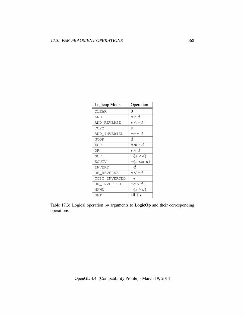
17.3. PER-FRAGMENT OPERATIONS 568
Logicop Mode OperationCLEAR 0
AND s ∧ dAND_REVERSE s ∧ ¬dCOPY s
AND_INVERTED ¬s ∧ dNOOP d
XOR s xor d
OR s ∨ dNOR ¬(s ∨ d)
EQUIV ¬(s xor d)
INVERT ¬dOR_REVERSE s ∨ ¬dCOPY_INVERTED ¬sOR_INVERTED ¬s ∨ dNAND ¬(s ∧ d)
SET all 1’s
Table 17.3: Logical operation op arguments to LogicOp and their correspondingoperations.
OpenGL 4.4 (Compatibility Profile) - March 19, 2014
17.3. PER-FRAGMENT OPERATIONS 569
the logical operation, and two bits indicating whether the logical operation is en-abled or disabled. The initial state is for the logic operation to be given by COPY,and to be disabled.
Errors
An INVALID_VALUE error is generated if op is not one of the logicopmodes in table 17.3.
17.3.12 Additional Multisample Fragment Operations
If the DrawBuffer mode (see section 17.4.1) is NONE, no change is made to anymultisample or color buffer. Otherwise, fragment processing is as described below.
If MULTISAMPLE is enabled, and the value of SAMPLE_BUFFERS is one, thealpha test, stencil test, depth test, blending, dithering, and logical operations areperformed for each pixel sample, rather than just once for each fragment. Failureof the alpha, stencil, or depth test results in termination of the processing of thatsample, rather than discarding of the fragment. All operations are performed on thecolor, depth, and stencil values stored in the multisample renderbuffer attachmentsif a draw framebuffer object is bound, or otherwise in the multisample buffer ofthe default framebuffer. The contents of the color buffers are not modified at thispoint.
Stencil, depth, blending, dithering, and logical operations are performed fora pixel sample only if that sample’s fragment coverage bit is a value of 1. If thecorresponding coverage bit is 0, no operations are performed for that sample.
If MULTISAMPLE is disabled, and the value of SAMPLE_BUFFERS is one, thefragment may be treated exactly as described above, with optimization possiblebecause the fragment coverage must be set to full coverage. Further optimization isallowed, however. An implementation may choose to identify a centermost sample,and to perform alpha, stencil, and depth tests on only that sample. Regardless ofthe outcome of the stencil test, all multisample buffer stencil sample values are setto the appropriate new stencil value. If the depth test passes, all multisample bufferdepth sample values are set to the depth of the fragment’s centermost sample’sdepth value, and all multisample buffer color sample values are set to the colorvalue of the incoming fragment. Otherwise, no change is made to any multisamplebuffer color or depth value.
If a draw framebuffer object is not bound, after all operations have been com-pleted on the multisample buffer, the sample values for each color in the multisam-ple buffer are combined to produce a single color value, and that value is writteninto the corresponding color buffers selected by DrawBuffer or DrawBuffers. An
OpenGL 4.4 (Compatibility Profile) - March 19, 2014
17.4. WHOLE FRAMEBUFFER OPERATIONS 570
implementation may defer the writing of the color buffers until a later time, but thestate of the framebuffer must behave as if the color buffers were updated as eachfragment was processed. The method of combination is not specified. If the frame-buffer contains sRGB values, then it is recommended that the an average of sam-ple values is computed in a linearized space, as for blending (see section 17.3.8).Otherwise, a simple average computed independently for each color component isrecommended.
17.4 Whole Framebuffer Operations
The preceding sections described the operations that occur as individual fragmentsare sent to the framebuffer. This section describes operations that control or affectthe whole framebuffer.
17.4.1 Selecting Buffers for Writing
The first such operation is controlling the color buffers into which each of thefragment color values is written. This is accomplished with either DrawBuffer orDrawBuffers.
The set of buffers to which fragment color zero is written is controlled with thecommand
void DrawBuffer( enum buf );
If the GL is bound to the default framebuffer (see section 9), buf must be one of thevalues listed in table 17.4. In this case, buf is a symbolic constant specifying zero,one, two, or four buffers for writing. These constants refer to the four potentiallyvisible buffers (front left, front right, back left, and back right), and to the auxiliarybuffers. Arguments other than AUXi that omit reference to LEFT or RIGHT referto both left and right buffers. Arguments other than AUXi that omit reference toFRONT or BACK refer to both front and back buffers. AUXi enables drawing onlyto auxiliary buffer i. Each AUXi adheres to AUXi = AUX0 + i, and i must be in therange zero to the value of AUX_BUFFERS minus one.
If the GL is bound to a draw framebuffer object, buf must be one of the valueslisted in table 17.5, which summarizes the constants and the buffers they indicate.In this case, buf is a symbolic constant specifying a single color buffer for writing.Specifying COLOR_ATTACHMENTi enables drawing only to the image attached tothe framebuffer at that attachment point.
OpenGL 4.4 (Compatibility Profile) - March 19, 2014
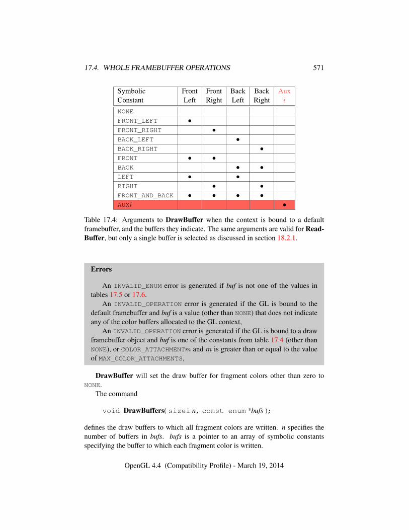
17.4. WHOLE FRAMEBUFFER OPERATIONS 571
Symbolic Front Front Back Back AuxConstant Left Right Left Right i
NONE
FRONT_LEFT •FRONT_RIGHT •BACK_LEFT •BACK_RIGHT •FRONT • •BACK • •LEFT • •RIGHT • •FRONT_AND_BACK • • • •AUXi •
Table 17.4: Arguments to DrawBuffer when the context is bound to a defaultframebuffer, and the buffers they indicate. The same arguments are valid for Read-Buffer, but only a single buffer is selected as discussed in section 18.2.1.
Errors
An INVALID_ENUM error is generated if buf is not one of the values intables 17.5 or 17.6.
An INVALID_OPERATION error is generated if the GL is bound to thedefault framebuffer and buf is a value (other than NONE) that does not indicateany of the color buffers allocated to the GL context,
An INVALID_OPERATION error is generated if the GL is bound to a drawframebuffer object and buf is one of the constants from table 17.4 (other thanNONE), or COLOR_ATTACHMENTm and m is greater than or equal to the valueof MAX_COLOR_ATTACHMENTS,
DrawBuffer will set the draw buffer for fragment colors other than zero toNONE.
The command
void DrawBuffers( sizei n, const enum *bufs );
defines the draw buffers to which all fragment colors are written. n specifies thenumber of buffers in bufs. bufs is a pointer to an array of symbolic constantsspecifying the buffer to which each fragment color is written.
OpenGL 4.4 (Compatibility Profile) - March 19, 2014
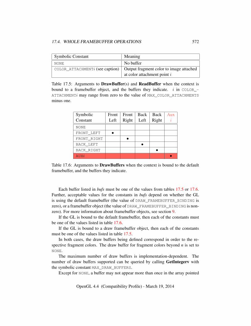
17.4. WHOLE FRAMEBUFFER OPERATIONS 572
Symbolic Constant MeaningNONE No bufferCOLOR_ATTACHMENTi (see caption) Output fragment color to image attached
at color attachment point i
Table 17.5: Arguments to DrawBuffer(s) and ReadBuffer when the context isbound to a framebuffer object, and the buffers they indicate. i in COLOR_-
ATTACHMENTi may range from zero to the value of MAX_COLOR_ATTACHMENTSminus one.
Symbolic Front Front Back Back AuxConstant Left Right Left Right i
NONE
FRONT_LEFT •FRONT_RIGHT •BACK_LEFT •BACK_RIGHT •AUXi •
Table 17.6: Arguments to DrawBuffers when the context is bound to the defaultframebuffer, and the buffers they indicate.
Each buffer listed in bufs must be one of the values from tables 17.5 or 17.6.Further, acceptable values for the constants in bufs depend on whether the GLis using the default framebuffer (the value of DRAW_FRAMEBUFFER_BINDING iszero), or a framebuffer object (the value of DRAW_FRAMEBUFFER_BINDING is non-zero). For more information about framebuffer objects, see section 9.
If the GL is bound to the default framebuffer, then each of the constants mustbe one of the values listed in table 17.6.
If the GL is bound to a draw framebuffer object, then each of the constantsmust be one of the values listed in table 17.5.
In both cases, the draw buffers being defined correspond in order to the re-spective fragment colors. The draw buffer for fragment colors beyond n is set toNONE.
The maximum number of draw buffers is implementation-dependent. Thenumber of draw buffers supported can be queried by calling GetIntegerv withthe symbolic constant MAX_DRAW_BUFFERS.
Except for NONE, a buffer may not appear more than once in the array pointed
OpenGL 4.4 (Compatibility Profile) - March 19, 2014
17.4. WHOLE FRAMEBUFFER OPERATIONS 573
to by bufs.If fixed-function fragment shading is being performed, DrawBuffers specifies
a set of draw buffers into which the fragment color is written.If a fragment shader writes to gl_FragColor, DrawBuffers specifies a set
of draw buffers into which the single fragment color defined by gl_FragColor
is written. If a fragment shader writes to gl_FragData or a user-defined outputvariable, DrawBuffers specifies a set of draw buffers into which each of the mul-tiple output colors defined by these variables are separately written. If a fragmentshader writes to none of gl_FragColor, gl_FragData, nor any user-definedoutput variables, the values of the fragment colors following shader execution areundefined, and may differ for each fragment color. If some, but not all elementsof gl_FragData or of theser-defined output variables are written, the values offragment colors corresponding to unwritten elements orariables are similarly un-defined.
The order of writes to gl_FragData and to user-defined output variables isundefined. If the same image is attached to multiple attachment points of a frame-buffer object and different values are written to outputs bound to those attachments,the resulting value in the attached image is undefined. Similarly undefined behaviorresults during any other per-fragment operations where a multiply-attached imagemay be written to by more than one output, such as during blending.
Errors
An INVALID_VALUE error is generated if n is negative, or greater than thevalue of MAX_DRAW_BUFFERS.
An INVALID_ENUM error is generated if any value in bufs is not one of thevalues in tables 17.5 or 17.6.
An INVALID_OPERATION error is generated if a buffer other than NONE
is specified more than once in the array pointed to by bufs.An INVALID_ENUM error is generated if any of the constants FRONT,
BACK, LEFT, RIGHT, or FRONT_AND_BACK are present in the bufs array passedto DrawBuffers. This restriction applies to both the default framebuffer andframebuffer objects, and exists because these constants may themselves referto multiple buffers, as shown in table 17.4.
An INVALID_OPERATION error is generated if the GL is bound to thedefault framebuffer and DrawBuffers is supplied with a constant (other thanNONE) that does not indicate any of the color buffers allocated to the GL con-text by the window system,
An INVALID_OPERATION error is generated if the GL is bound to a drawframebuffer object and DrawBuffers is supplied with a constant from ta-
OpenGL 4.4 (Compatibility Profile) - March 19, 2014
17.4. WHOLE FRAMEBUFFER OPERATIONS 574
ble 17.6, or COLOR_ATTACHMENTm where m is greater than or equal to thevalue of MAX_COLOR_ATTACHMENTS.
Indicating a buffer or buffers using DrawBuffer or DrawBuffers causes sub-sequent pixel color value writes to affect the indicated buffers. If the GL is boundto a draw framebuffer object and a draw buffer selects an attachment that has noimage attached, then that fragment color is not written.
Specifying NONE as the draw buffer for a fragment color will inhibit that frag-ment color from being written.
Monoscopic contexts include only left buffers, while stereoscopic contexts in-clude both left and right buffers. Likewise, single buffered contexts include onlyfront buffers, while double buffered contexts include both front and back buffers.The type of context is selected at GL initialization.
The state required to handle color buffer selection for each framebuffer is aninteger for each supported fragment color. For the default framebuffer, in the initialstate the draw buffer for fragment color zero is BACK if there is a back buffer;FRONT if there is no back buffer; and NONE if no default framebuffer is associatedwith the context. For framebuffer objects, in the initial state the draw buffer forfragment color zero is COLOR_ATTACHMENT0. For both the default framebufferand framebuffer objects, the initial state of draw buffers for fragment colors otherthen zero is NONE.
The draw buffer of the currently bound draw framebuffer selected for fragmentcolor i can be queried by calling GetIntegerv with pname set to DRAW_BUFFERi.DRAW_BUFFER is equivalent to DRAW_BUFFER0.
17.4.2 Fine Control of Buffer Updates
Writing of bits to each of the logical framebuffers after all per-fragment operationshave been performed may be masked. The commands
void IndexMask( uint mask );void ColorMask( boolean r, boolean g, boolean b,
boolean a );void ColorMaski( uint buf, boolean r, boolean g,
boolean b, boolean a );
control writes to the active draw buffers.The least significant n bits of mask, where n is the number of bits in a color
index buffer, specify a mask. Where a 1 appears in this mask, the correspondingbit in the color index buffer (or buffers) is written; where a 0 appears, the bit is notwritten. This mask applies only in color index mode.
OpenGL 4.4 (Compatibility Profile) - March 19, 2014
17.4. WHOLE FRAMEBUFFER OPERATIONS 575
In RGBA mode, ColorMask and ColorMaski are used to mask the writing ofR, G, B and A values to the draw buffer or buffers. ColorMaski sets the maskfor a particular draw buffer. The mask for DRAW_BUFFERi is modified by passingi as the parameter buf. r, g, b, and a indicate whether R, G, B, or A values, re-spectively, are written or not (a value of TRUE means that the corresponding valueis written). The mask specified by r, g, b, and a is applied to the color buffer as-sociated with DRAW_BUFFERi. If DRAW_BUFFERi is one of FRONT, BACK, LEFT,RIGHT, or FRONT_AND_BACK (specifying multiple color buffers) then the mask isapplied to all of the buffers.
ColorMask sets the mask for all draw buffers to the same values as specifiedby r, g, b, and a.
Errors
An INVALID_VALUE error is generated by ColorMaski if buf is greaterthan the value of MAX_DRAW_BUFFERS minus one.
In the initial state, all bits (in color index mode) and all color values (in RGBAmode) are enabled for writing for all draw buffers.
The value of the color writemask for draw buffer i can be queried by callingGetBooleani v with target COLOR_WRITEMASK and index i. The value of the colorwritemask for draw buffer zero may also be queried by calling GetBooleanv withthe symbolic constant COLOR_WRITEMASK.
The depth buffer can be enabled or disabled for writing zw values using
void DepthMask( boolean mask );
If mask is non-zero, the depth buffer is enabled for writing; otherwise, it is disabled.In the initial state, the depth buffer is enabled for writing.
The commands
void StencilMask( uint mask );void StencilMaskSeparate( enum face, uint mask );
control the writing of particular bits into the stencil planes.The least significant s bits of mask, where s is the number of bits in the stencil
buffer, specify an integer mask. Where a 1 appears in this mask, the correspondingbit in the stencil buffer is written; where a 0 appears, the bit is not written. The faceparameter of StencilMaskSeparate can be FRONT, BACK, or FRONT_AND_BACKand indicates whether the front or back stencil mask state is affected. StencilMasksets both front and back stencil mask state to identical values.
OpenGL 4.4 (Compatibility Profile) - March 19, 2014
17.4. WHOLE FRAMEBUFFER OPERATIONS 576
Fragments generated by front-facing primitives use the front mask and frag-ments generated by back-facing primitives use the back mask (see section 17.3.5).The clear operation always uses the front stencil write mask when clearing thestencil buffer.
The state required for the various masking operations is an integer for colorindices, two integers for the front and back stencil values, and a bit for depth values.A set of four bits is also required indicating which color components of an RGBAvalue should be written. In the initial state, the integer masks are all ones, as arethe bits controlling depth value and RGBA component writing.
17.4.2.1 Fine Control of Multisample Buffer Updates
When the value of SAMPLE_BUFFERS is one, ColorMask, DepthMask, and Sten-cilMask or StencilMaskSeparate control the modification of values in the multi-sample buffer. The color mask has no effect on modifications to the color buffers.If the color mask is entirely disabled, the color sample values must still be com-bined (as described above) and the result used to replace the color values of thebuffers enabled by DrawBuffer.
17.4.3 Clearing the Buffers
The GL provides a means for setting portions of every pixel in a particular bufferto the same value. The argument to
void Clear( bitfield buf );
is zero or the bitwise OR of one or more values indicating which buffers are tobe cleared. The values are ACCUM_BUFFER_BIT, COLOR_BUFFER_BIT, DEPTH_-BUFFER_BIT, and STENCIL_BUFFER_BIT, indicating the accumulation buffer,the buffers currently enabled for color writing, the depth buffer, and the stencilbuffer (see below), respectively. The value to which each buffer is cleared dependson the setting of the clear value for that buffer. If buf is zero, no buffers are cleared.
Errors
An INVALID_VALUE error is generated if buf contains any bits otherthan ACCUM_BUFFER_BIT, COLOR_BUFFER_BIT, DEPTH_BUFFER_BIT, orSTENCIL_BUFFER_BIT.
void ClearColor( float r, float g, float b, float a );
OpenGL 4.4 (Compatibility Profile) - March 19, 2014
17.4. WHOLE FRAMEBUFFER OPERATIONS 577
sets the clear value for fixed-point and floating-point color buffers in RGBA mode.The specified components are stored as floating-point values.
The command
void ClearIndex( float index );
sets the clear color index. index is converted to a fixed-point value with unspecifiedprecision to the left of the binary point; the integer part of this value is then maskedwith 2m − 1, where m is the number of bits in a color index value stored in theframebuffer.
The command
void ClearDepth( double d );void ClearDepthf( float d );
sets the depth value used when clearing the depth buffer. d is clamped to the range[0, 1] when specified. When clearing a fixed-point depth buffer, d is converted tofixed-point according to the rules for a window z value given in section 13.6.1. Noconversion is applied when clearing a floating-point depth buffer.
The command
void ClearStencil( int s );
takes a single integer argument that is the value to which to clear the stencil buffer.s is masked to the number of bitplanes in the stencil buffer.
The command
void ClearAccum( float r, float g, float b, float a );
takes four floating-point arguments that are the values, in order, to which to set theR, G, B, and A values of the accumulation buffer (see the next section). Thesevalues are clamped to the range [−1, 1] when they are specified.
When Clear is called, the only per-fragment operations that are applied (ifenabled) are the pixel ownership test, the scissor test, sRGB conversion (see sec-tion 17.3.9), and dithering. The masking operations described in section 17.4.2 arealso applied. If a buffer is not present, then a Clear directed at that buffer has noeffect.
Unsigned normalized fixed-point and signed normalized fixed-point RGBAcolor buffers are cleared to color values derived by clamping each component of theclear color to the range [0, 1] or [−1, 1] respectively, then converting the (possibly
OpenGL 4.4 (Compatibility Profile) - March 19, 2014
17.4. WHOLE FRAMEBUFFER OPERATIONS 578
sRGB converted and/or dithered) color to fixed-point using equations 2.3 or 2.4,respectively. The result of clearing integer color buffers is undefined.
The state required for clearing is a clear value for each of the color buffer,the accumulation buffer, the depth buffer, and the stencil buffer. Initially, theRGBA color clear value is (0.0, 0.0, 0.0, 0.0), the accumulation buffer clear valueis (0.0, 0.0, 0.0, 0.0), the clear color index is 0, the depth buffer clear value is 1.0,and the stencil buffer clear index is 0.
17.4.3.1 Clearing Individual Buffers
Individual buffers of the currently bound draw framebuffer may be cleared with thecommand
void ClearBuffer{if ui}v( enum buffer, int drawbuffer,const T *value );
where buffer and drawbuffer identify a buffer to clear, and value specifies the valueor values to clear it to. ClearBufferfv, ClearBufferiv, and ClearBufferuiv shouldbe used to clear fixed- and floating-point, signed integer, and unsigned integer colorbuffers respectively.
If buffer is COLOR, a particular draw buffer DRAW_BUFFERi is specified bypassing i as the parameter drawbuffer, and value points to a four-element vec-tor specifying the R, G, B, and A color to clear that draw buffer to. If the valueof DRAW_BUFFERi is NONE, the command has no effect. Otherwise, the value ofDRAW_BUFFERi is one of the possible values in tables 17.4 and 17.6 identifyingone or more color buffers, each of which is cleared to the same value. Clampingand conversion for fixed-point color buffers are performed in the same fashion asClearColor.
If buffer is DEPTH, drawbuffer must be zero, and value points to the singledepth value to clear the depth buffer to. Clamping and type conversion for fixed-point depth buffers are performed in the same fashion as ClearDepth. Only Clear-Bufferfv should be used to clear depth buffers; neither ClearBufferiv nor Clear-Bufferuiv accept a buffer of DEPTH.
If buffer is STENCIL, drawbuffer must be zero, and value points to the singlestencil value to clear the stencil buffer to. Masking is performed in the same fash-ion as ClearStencil. Only ClearBufferiv should be used to clear stencil buffers;neither ClearBufferfv nor ClearBufferuiv accept a buffer of STENCIL.
The command
void ClearBufferfi( enum buffer, int drawbuffer,float depth, int stencil );
OpenGL 4.4 (Compatibility Profile) - March 19, 2014
17.4. WHOLE FRAMEBUFFER OPERATIONS 579
clears both depth and stencil buffers of the currently bound draw framebuffer.buffer must be DEPTH_STENCIL and drawbuffer must be zero. depth and sten-cil are the values to clear the depth and stencil buffers to, respectively. Clampingand type conversion of depth for fixed-point depth buffers is performed in the samefashion as ClearDepth. Masking of stencil for stencil buffers is performed in thesame fashion as ClearStencil. ClearBufferfi is equivalent to clearing the depthand stencil buffers separately, but may be faster when a buffer of internal formatDEPTH_STENCIL is being cleared. The same per-fragment and masking operationsdefined for Clear are applied.
The result of these commands is undefined if no conversion between the type ofthe specified value and the type of the buffer being cleared is defined (for example,if ClearBufferiv is called for a fixed- or floating-point buffer, or if ClearBufferfvis called for a signed or unsigned integer buffer). This is not an error.
Errors
An INVALID_ENUM error is generated by ClearBufferiv if buffer is notCOLOR or STENCIL.
An INVALID_ENUM error is generated by ClearBufferuiv if buffer is notCOLOR.
An INVALID_ENUM error is generated by ClearBufferfv if buffer is notCOLOR or DEPTH.
An INVALID_ENUM error is generated by ClearBufferfi if buffer is notDEPTH_STENCIL.
An INVALID_VALUE error is generated if buffer is COLOR and drawbufferis negative, or greater than the value of MAX_DRAW_BUFFERS minus one; or ifbuffer is DEPTH, STENCIL, or DEPTH_STENCIL and drawbuffer is not zero.
An INVALID_OPERATION error is generated if buffer is COLOR and theGL is in color index mode.
17.4.3.2 Clearing the Multisample Buffer
The color samples of the multisample buffer are cleared when one or more colorbuffers are cleared, as specified by the Clear mask bit COLOR_BUFFER_BIT andthe DrawBuffer mode. If the DrawBuffer mode is NONE, the color samples of themultisample buffer cannot be cleared using Clear.
If the Clear mask bits DEPTH_BUFFER_BIT or STENCIL_BUFFER_BIT areset, then the corresponding depth or stencil samples, respectively, are cleared.
The ClearBuffer* commands also clear color, depth, or stencil samples ofmultisample buffers corresponding to the specified buffer.
OpenGL 4.4 (Compatibility Profile) - March 19, 2014
17.4. WHOLE FRAMEBUFFER OPERATIONS 580
Masking and scissoring affect clearing the multisample buffer in the same wayas they affect clearing the corresponding color, depth, and stencil buffers.
17.4.4 Invalidating Framebuffer Contents
The GL provides a means for invalidating portions of every pixel or a subregionof pixels in a particular buffer, effectively leaving their contents undefined. Thecommand
void InvalidateSubFramebuffer( enum target,sizei numAttachments, const enum *attachments, int x,int y, sizei width, sizei height );
signals the GL that it need not preserve all contents of a bound framebuffer object.numAttachments indicates how many attachments are supplied in the attachmentslist. If an attachment is specified that does not exist in the framebuffer boundto target, it is ignored. target must be FRAMEBUFFER, DRAW_FRAMEBUFFER, orREAD_FRAMEBUFFER. FRAMEBUFFER is treated as DRAW_FRAMEBUFFER. x and yare the origin (with lower left-hand corner at (0, 0)) and width and height are thewidth and height, respectively, of the pixel rectangle to be invalidated. Any of thesepixels lying outside of the window allocated to the current GL context, or outsideof the attachments of the currently bound framebuffer object, are ignored.
If the framebuffer object is not complete, InvalidateFramebuffer may be ig-nored.
Errors
An INVALID_ENUM error is generated if a framebuffer object is boundto target and any elements of attachments are not one of the attachments intable 9.1.
An INVALID_OPERATION error is generated if attachments containsCOLOR_ATTACHMENTmwherem is greater than or equal to the value of MAX_-COLOR_ATTACHMENTS.
An INVALID_VALUE error is generated if numAttachments, width, orheight is negative.
An INVALID_ENUM error is generated if the default framebuffer is boundto target and any elements of attachments are not one of:• ACCUM, AUXi, FRONT_LEFT, FRONT_RIGHT, BACK_LEFT, and BACK_-RIGHT, identifying that specific buffer
• COLOR, which is treated as BACK_LEFT for a double-buffered context
OpenGL 4.4 (Compatibility Profile) - March 19, 2014
17.4. WHOLE FRAMEBUFFER OPERATIONS 581
and FRONT_LEFT for a single-buffered context
• DEPTH, identifying the depth buffer
• STENCIL, identifying the stencil buffer.
The command
void InvalidateFramebuffer( enum target,sizei numAttachments, const enum *attachments );
is equivalent to
InvalidateSubFramebuffer(target, numAttachments, attachments,0, 0, vw, vh);
where vw and vh are equal to the maximum viewport width and height, respctively,obtained by querying MAX_VIEWPORT_DIMS.
17.4.5 The Accumulation Buffer
Each portion of a pixel in the accumulation buffer consists of four values: one foreach of R, G, B, and A. The accumulation buffer is controlled exclusively throughthe use of
void Accum( enum op, float value );
(except for clearing it). op is a symbolic constant indicating an accumulation bufferoperation, and value is a floating-point value to be used in that operation. Thepossible operations are ACCUM, LOAD, RETURN, MULT, and ADD.
When the scissor test is enabled (section 17.3.2), then only those pixels withinthe current scissor box are updated by any Accum operation; otherwise, all pixelsin the window are updated. The accumulation buffer operations apply identicallyto every affected pixel, so we describe the effect of each operation on an individ-ual pixel. Accumulation buffer values are taken to be signed values in the range[−1, 1].
Using ACCUM obtains R, G, B, and A components from the buffer currentlyselected for reading (section 18.2). If the color buffer is fixed-point, each com-ponent is considered as an unsigned normalized value in the range [0, 1] and isconverted to floating-point using equation 2.1. If FRAMEBUFFER_SRGB is enabledand the value of FRAMEBUFFER_ATTACHMENT_COLOR_ENCODING for the frame-buffer attachment corresponding to the buffer selected for reading is SRGB (see
OpenGL 4.4 (Compatibility Profile) - March 19, 2014
17.4. WHOLE FRAMEBUFFER OPERATIONS 582
section 9.2.3), then the floating-point R, G, and B components are considered tobe encoded for the sRGB color space and are linearized using equation 8.14. Eachcomponent is then multiplied by value. The result of this multiplication is thenadded to the corresponding color component currently in the accumulation buffer,replacing that component.
The LOAD operation has the same effect as ACCUM, but the computed valuesreplace the corresponding accumulation buffer components rather than being addedto them.
The RETURN operation takes each color value from the accumulation buffer,multiplies each of the R, G, B, and A components by value. If fragment colorclamping is enabled, the results are then clamped to the range [0, 1]. The resultingcolor value is placed in the buffers currently enabled for color writing as if it werea fragment produced from rasterization, except that the only per-fragment opera-tions that are applied (if enabled) are the pixel ownership test, the scissor test (sec-tion 17.3.2), sRGB conversion (see section 17.3.9), and dithering (section 17.3.10).Color masking (section 17.4.2) is also applied.
The MULT operation multiplies each R, G, B, and A in the accumulation bufferby value and then returns the scaled color components to their corresponding ac-cumulation buffer locations. ADD is the same as MULT except that value is added toeach of the color components.
The color components operated on by Accum must be clamped only if theoperation is RETURN. In this case, a value sent to the enabled color buffers is firstclamped to [0, 1]. Otherwise, results are undefined if the result of an operation ona color component is out of the range [−1, 1].
Errors
An INVALID_OPERATION error is generated if there is no accumulationbuffer; if the DRAW_FRAMEBUFFER and READ_FRAMEBUFFER bindings (seesection 9.4.2) do not refer to the same object; or if the GL is in color indexmode,
No state (beyond the accumulation buffer itself) is required for accumulationbuffering.
OpenGL 4.4 (Compatibility Profile) - March 19, 2014
Chapter 18
Drawing, Reading, and CopyingPixels
Pixels may be written to the framebuffer using DrawPixels and read from theframebuffer using ReadPixels. CopyPixels and BlitFramebuffer can be used tocopy a block of pixels from one portion of the framebuffer to another.
18.1 Drawing Pixels
Pixel rectangles may be drawn using the command
void DrawPixels( sizei width, sizei height, enum format,enum type, const void *data );
Results of rasterization are undefined if any of the selected draw buffers of thedraw framebuffer have an integer format and no fragment shader is active.
Errors
An INVALID_VALUE error is generated if width or height is negative.An INVALID_OPERATION error is generated if the GL is in color index
mode and format is not one of COLOR_INDEX, STENCIL_INDEX, DEPTH_-COMPONENT, or DEPTH_STENCIL.
An INVALID_OPERATION error is generated if format contains integercomponents, as shown in table 8.8.
An INVALID_FRAMEBUFFER_OPERATION error is generated if the object
583
18.1. DRAWING PIXELS 584
bound to DRAW_FRAMEBUFFER_BINDING is not framebuffer complete (seesection 9.4.2).
Calling DrawPixels with a type of BITMAP is a special case in which the dataare a series of GL ubyte values. Each ubyte value specifies 8 1-bit elementswith its 8 least-significant bits. The 8 single-bit elements are ordered from mostsignificant to least significant if the value of UNPACK_LSB_FIRST is FALSE; oth-erwise, the ordering is from least significant to most significant. The values of bitsother than the 8 least significant in each ubyte are not significant.
The first element of the first row is the first bit (as defined above) of the ubytepointed to by the pointer passed to DrawPixels. The first element of the secondrow is the first bit (again as defined above) of the ubyte at location p+ k, wherek is computed as
k = a
⌈l
8a
⌉(18.1)
There is a mechanism for selecting a sub-rectangle of elements from a BITMAPimage as well. Before obtaining the first element from memory, the pointer sup-plied to DrawPixels is effectively advanced by UNPACK_SKIP_ROWS∗k ubytes.Then UNPACK_SKIP_PIXELS 1-bit elements are ignored, and the subsequentwidth 1-bit elements are obtained, without advancing the ubyte pointer, afterwhich the pointer is advanced by k ubytes. height sets of width elements areobtained this way.
Once pixels are transferred, DrawPixels performs final conversion on pixelvalues (see section 18.1.1, then converts them to fragments (see section 18.1.2which are processed in the same fashion as fragments generated by rasterization(see chapters 15 and 16).
18.1.1 Final Conversion
For a color index, final conversion consists of masking the bits of the index to theleft of the binary point by 2n − 1, where n is the number of bits in an index buffer.
For integer RGBA components, no conversion is performed. For floating-point RGBA components, if fragment color clamping is enabled, each elementis clamped to [0, 1], and may be converted to fixed-point according to equation 2.3.If fragment color clamping is disabled, RGBA components are unmodified. Frag-ment color clamping is controlled by calling
void ClampColor( enum target, enum clamp );
OpenGL 4.4 (Compatibility Profile) - March 19, 2014
18.1. DRAWING PIXELS 585
with target set to CLAMP_FRAGMENT_COLOR. If clamp is TRUE, fragment colorclamping is enabled; if clamp is FALSE, fragment color clamping is disabled. Ifclamp is FIXED_ONLY, fragment color clamping is enabled if all enabled colorbuffers have fixed-point components.
If fragment color clamping is enabled, querying of the texture border color,texture environment color, fog color, alpha test reference value, blend color, andRGBA clear color will clamp the corresponding state values to [0, 1] before return-ing them. This behavior provides compatibility with previous versions of the GLthat clamped these values when specified.
For a depth component, an element is processed according to the depth buffer’srepresentation. For fixed-point depth buffers, the element is first clamped to therange [0, 1] and then converted to fixed-point as if it were a window z value (seesection 13.6.1). Conversion is not necessary when the depth buffer uses a floating-point representation, but clamping is.
Stencil indices are masked by 2n − 1, where n is the number of bits in thestencil buffer.
The state required for fragment color clamping is a three-valued integer. Theinitial value of fragment color clamping is FIXED_ONLY.
18.1.2 Conversion to Fragments
The conversion of a group to fragments is controlled with
void PixelZoom( float zx, float zy );
Let (xrp, yrp) be the current raster position (section 14.7). (If the current rasterposition is invalid, then DrawPixels is ignored; pixel transfer operations do notupdate the histogram or minmax tables, and no fragments are generated. However,the histogram and minmax tables are updated even if the corresponding fragmentsare later rejected by the pixel ownership (section 17.3.1) or scissor (section 17.3.2)tests.) If a particular group (index or components) is the nth in a row and belongs tothe mth row, consider the region in window coordinates bounded by the rectanglewith corners
(xrp + zxn, yrp + zym) and (xrp + zx(n+ 1), yrp + zy(m+ 1))
(either zx or zy may be negative). A fragment representing group (n,m) is pro-duced for each framebuffer pixel inside, or on the bottom or left boundary, of thisrectangle.
A fragment arising from a group consisting of color data takes on the colorindex or color components of the group and the current raster position’s associated
OpenGL 4.4 (Compatibility Profile) - March 19, 2014
18.1. DRAWING PIXELS 586
depth value, while a fragment arising from a depth component takes that compo-nent’s depth value and the current raster position’s associated color index or colorcomponents. In both cases, the fog coordinate is taken from the current raster posi-tion’s associated raster distance, the secondary color is taken from the current rasterposition’s associated secondary color, and texture coordinates are taken from thecurrent raster position’s associated texture coordinates. Groups arising from Draw-Pixels with a format of DEPTH_STENCIL or STENCIL_INDEX are treated speciallyand are described in section 18.1.4.
18.1.3 Pixel Rectangle Multisample Rasterization
If MULTISAMPLE is enabled, and the value of SAMPLE_BUFFERS is one, then pixelrectangles are rasterized using the following algorithm. Let (Xrp, Yrp) be the cur-rent raster position. (If the current raster position is invalid, then DrawPixels isignored.) If a particular group (index or components) is the nth in a row and be-longs to the mth row, consider the region in window coordinates bounded by therectangle with corners
(Xrp + Zx ∗ n, Yrp + Zy ∗m)
and(Xrp + Zx ∗ (n+ 1), Yrp + Zy ∗ (m+ 1))
where Zx and Zy are the pixel zoom factors specified by PixelZoom, and may eachbe either positive or negative. A fragment representing group (n,m) is producedfor each framebuffer pixel with one or more sample points that lie inside, or onthe bottom or left boundary, of this rectangle. Each fragment so produced takes itsassociated data from the group and from the current raster position, in a mannerconsistent with the discussion in section 18.1.2. All depth and color sample valuesare assigned the same value, taken either from their group (for depth and colorcomponent groups) or from the current raster position (if they are not). All samplevalues are assigned the same fog coordinate and the same set of texture coordinates,taken from the current raster position.
A single pixel rectangle will generate multiple, perhaps very many fragmentsfor the same framebuffer pixel, depending on the pixel zoom factors.
18.1.4 Writing to the Stencil or Depth/Stencil Buffers
If the format argument to DrawPixels is STENCIL_INDEX or DEPTH_STENCIL,all operations described for DrawPixels take place, but window (x, y) coordinates,each with the corresponding stencil index, or depth value and stencil index, are
OpenGL 4.4 (Compatibility Profile) - March 19, 2014
18.2. READING PIXELS 587
produced in lieu of fragments. Each coordinate-data pair is sent directly to the per-fragment operations, bypassing the fragment processing operations in chapters 15and 16. Each pair is then treated as a fragment for purposes of the pixel ownershipand scissor tests; all other per-fragment operations are bypassed. Finally, eachstencil index is written to its indicated location in the framebuffer, subject to thecurrent front stencil mask (set with StencilMask or StencilMaskSeparate). If adepth component is present, and the setting of DepthMask is not FALSE, it is alsowritten to the framebuffer; the setting of DepthFunc is ignored.
An INVALID_OPERATION error is generated if the format argument isSTENCIL_INDEX and there is no stencil buffer, or if format is DEPTH_STENCILand there is not both a depth buffer and a stencil buffer.
18.2 Reading Pixels
The method for reading pixels from the framebuffer and placing them in pixel packbuffer or client memory is diagrammed in figure 18.1. We describe the stages ofthe pixel reading process in the order in which they occur.
18.2.1 Selecting Buffers for Reading
When reading pixels from a color buffer, the buffer selected for reading is termedthe read buffer, and is controlled with the command
void ReadBuffer( enum src );
If the GL is bound to the default framebuffer (see section 9), src must be one of thevalues listed in table 17.4, including NONE. FRONT_AND_BACK, FRONT, and LEFT
refer to the front left buffer, BACK refers to the back left buffer, and RIGHT refersto the front right buffer. Other constants correspond directly to the buffers thatthey name. The initial value of the read framebuffer for the default framebuffer isFRONT if there is no back buffer; BACK if there is a back buffer; and NONE if nodefault framebuffer is associated with the context.
If the GL is bound to a read framebuffer object, src must be one of the val-ues listed in table 17.5, including NONE. Specifying COLOR_ATTACHMENTi en-ables reading from the image attached to the framebuffer at that attachment point.The initial value of the read framebuffer for framebuffer objects is COLOR_-
ATTACHMENT0.The read buffer of the currently bound read framebuffer can be queried by
calling GetIntegerv with pname set to READ_BUFFER.
OpenGL 4.4 (Compatibility Profile) - March 19, 2014
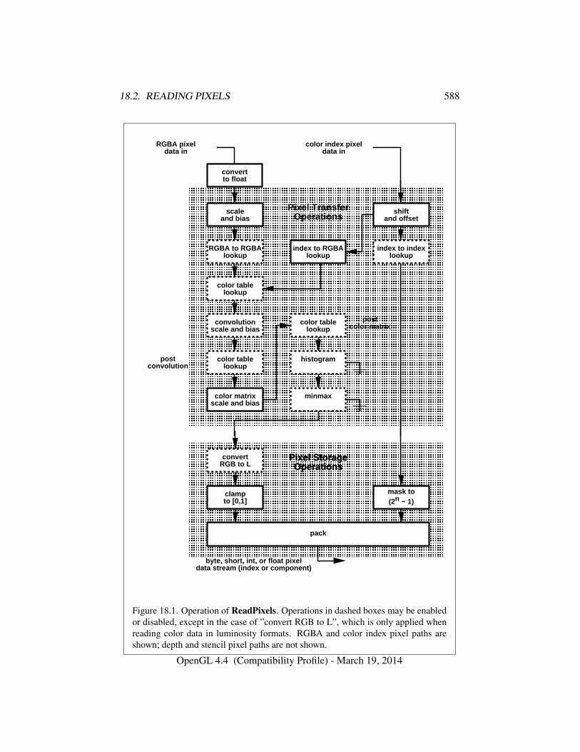
18.2. READING PIXELS 588
postconvolution
convertto float
RGBA pixeldata in
color index pixeldata in
� � � � � � � � � � � � � � � � � � � � � � � � � � � � � � �� � � � � � � � � � � � � � � � � � � � � � � � � � � � � � �� � � � � � � � � � � � � � � � � � � � � � � � � � � � � � �� � � � � � � � � � � � � � � � � � � � � � � � � � � � � � �� � � � � � � � � � � � � � � � � � � � � � � � � � � � � � �� � � � � � � � � � � � � � � � � � � � � � � � � � � � � � �� � � � � � � � � � � � � � � � � � � � � � � � � � � � � � �� � � � � � � � � � � � � � � � � � � � � � � � � � � � � � �� � � � � � � � � � � � � � � � � � � � � � � � � � � � � � �� � � � � � � � � � � � � � � � � � � � � � � � � � � � � � �� � � � � � � � � � � � � � � � � � � � � � � � � � � � � � �� � � � � � � � � � � � � � � � � � � � � � � � � � � � � � �� � � � � � � � � � � � � � � � � � � � � � � � � � � � � � �� � � � � � � � � � � � � � � � � � � � � � � � � � � � � � �� � � � � � � � � � � � � � � � � � � � � � � � � � � � � � �� � � � � � � � � � � � � � � � � � � � � � � � � � � � � � �� � � � � � � � � � � � � � � � � � � � � � � � � � � � � � �� � � � � � � � � � � � � � � � � � � � � � � � � � � � � � �� � � � � � � � � � � � � � � � � � � � � � � � � � � � � � �� � � � � � � � � � � � � � � � � � � � � � � � � � � � � � �� � � � � � � � � � � � � � � � � � � � � � � � � � � � � � �� � � � � � � � � � � � � � � � � � � � � � � � � � � � � � �� � � � � � � � � � � � � � � � � � � � � � � � � � � � � � �� � � � � � � � � � � � � � � � � � � � � � � � � � � � � � �� � � � � � � � � � � � � � � � � � � � � � � � � � � � � � �� � � � � � � � � � � � � � � � � � � � � � � � � � � � � � �� � � � � � � � � � � � � � � � � � � � � � � � � � � � � � �� � � � � � � � � � � � � � � � � � � � � � � � � � � � � � �� � � � � � � � � � � � � � � � � � � � � � � � � � � � � � �
scaleand bias
Pixel TransferOperations
color table lookup
convolution scale a nd bias
histogram
minmax
color table lookup
RGBA to RGBA lookup
shiftand offset
index to index look up
index to RGBA looku p
color table lookup
color matrixscale and bias
postcolor matrix
� � � � � � � � � � � � � � � � � � � � � � � � � � � � � � �� � � � � � � � � � � � � � � � � � � � � � � � � � � � � � �� � � � � � � � � � � � � � � � � � � � � � � � � � � � � � �� � � � � � � � � � � � � � � � � � � � � � � � � � � � � � �� � � � � � � � � � � � � � � � � � � � � � � � � � � � � � �� � � � � � � � � � � � � � � � � � � � � � � � � � � � � � �� � � � � � � � � � � � � � � � � � � � � � � � � � � � � � �� � � � � � � � � � � � � � � � � � � � � � � � � � � � � � �� � � � � � � � � � � � � � � � � � � � � � � � � � � � � � �� � � � � � � � � � � � � � � � � � � � � � � � � � � � � � �� � � � � � � � � � � � � � � � � � � � � � � � � � � � � � �� � � � � � � � � � � � � � � � � � � � � � � � � � � � � � �� � � � � � � � � � � � � � � � � � � � � � � � � � � � � � �� � � � � � � � � � � � � � � � � � � � � � � � � � � � � � �
pack
convertRGB to L
clampto [0,1]
mask to(2n − 1)
byte, short, int, o r float pixeldata stream (index or component)
Pixel StorageOperations
Figure 18.1. Operation of ReadPixels. Operations in dashed boxes may be enabledor disabled, except in the case of ”convert RGB to L”, which is only applied whenreading color data in luminosity formats. RGBA and color index pixel paths areshown; depth and stencil pixel paths are not shown.
OpenGL 4.4 (Compatibility Profile) - March 19, 2014
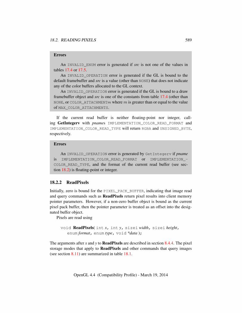
18.2. READING PIXELS 589
Errors
An INVALID_ENUM error is generated if src is not one of the values intables 17.4 or 17.5.
An INVALID_OPERATION error is generated if the GL is bound to thedefault framebuffer and src is a value (other than NONE) that does not indicateany of the color buffers allocated to the GL context.
An INVALID_OPERATION error is generated if the GL is bound to a drawframebuffer object and src is one of the constants from table 17.4 (other thanNONE, or COLOR_ATTACHMENTm wherem is greater than or equal to the valueof MAX_COLOR_ATTACHMENTS.
If the current read buffer is neither floating-point nor integer, call-ing GetIntegerv with pnames IMPLEMENTATION_COLOR_READ_FORMAT andIMPLEMENTATION_COLOR_READ_TYPE will return RGBA and UNSIGNED_BYTE,respectively.
Errors
An INVALID_OPERATION error is generated by GetIntegerv if pnameis IMPLEMENTATION_COLOR_READ_FORMAT or IMPLEMENTATION_-
COLOR_READ_TYPE, and the format of the current read buffer (see sec-tion 18.2) is floating-point or integer.
18.2.2 ReadPixels
Initially, zero is bound for the PIXEL_PACK_BUFFER, indicating that image readand query commands such as ReadPixels return pixel results into client memorypointer parameters. However, if a non-zero buffer object is bound as the currentpixel pack buffer, then the pointer parameter is treated as an offset into the desig-nated buffer object.
Pixels are read using
void ReadPixels( int x, int y, sizei width, sizei height,enum format, enum type, void *data );
The arguments after x and y to ReadPixels are described in section 8.4.4. The pixelstorage modes that apply to ReadPixels and other commands that query images(see section 8.11) are summarized in table 18.1.
OpenGL 4.4 (Compatibility Profile) - March 19, 2014
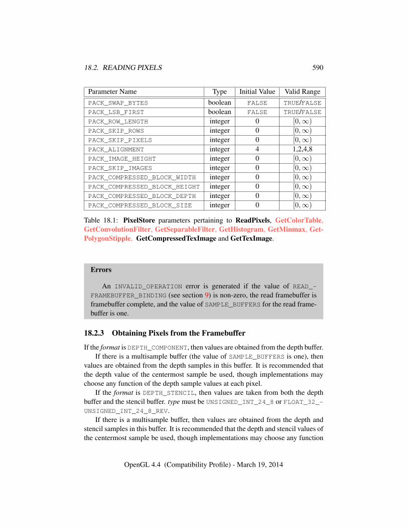
18.2. READING PIXELS 590
Parameter Name Type Initial Value Valid RangePACK_SWAP_BYTES boolean FALSE TRUE/FALSEPACK_LSB_FIRST boolean FALSE TRUE/FALSEPACK_ROW_LENGTH integer 0 [0,∞)
PACK_SKIP_ROWS integer 0 [0,∞)
PACK_SKIP_PIXELS integer 0 [0,∞)
PACK_ALIGNMENT integer 4 1,2,4,8PACK_IMAGE_HEIGHT integer 0 [0,∞)
PACK_SKIP_IMAGES integer 0 [0,∞)
PACK_COMPRESSED_BLOCK_WIDTH integer 0 [0,∞)
PACK_COMPRESSED_BLOCK_HEIGHT integer 0 [0,∞)
PACK_COMPRESSED_BLOCK_DEPTH integer 0 [0,∞)
PACK_COMPRESSED_BLOCK_SIZE integer 0 [0,∞)
Table 18.1: PixelStore parameters pertaining to ReadPixels, GetColorTable,GetConvolutionFilter, GetSeparableFilter, GetHistogram, GetMinmax, Get-PolygonStipple, GetCompressedTexImage and GetTexImage.
Errors
An INVALID_OPERATION error is generated if the value of READ_-
FRAMEBUFFER_BINDING (see section 9) is non-zero, the read framebuffer isframebuffer complete, and the value of SAMPLE_BUFFERS for the read frame-buffer is one.
18.2.3 Obtaining Pixels from the Framebuffer
If the format is DEPTH_COMPONENT, then values are obtained from the depth buffer.If there is a multisample buffer (the value of SAMPLE_BUFFERS is one), then
values are obtained from the depth samples in this buffer. It is recommended thatthe depth value of the centermost sample be used, though implementations maychoose any function of the depth sample values at each pixel.
If the format is DEPTH_STENCIL, then values are taken from both the depthbuffer and the stencil buffer. type must be UNSIGNED_INT_24_8 or FLOAT_32_-UNSIGNED_INT_24_8_REV.
If there is a multisample buffer, then values are obtained from the depth andstencil samples in this buffer. It is recommended that the depth and stencil values ofthe centermost sample be used, though implementations may choose any function
OpenGL 4.4 (Compatibility Profile) - March 19, 2014
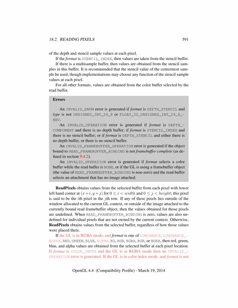
18.2. READING PIXELS 591
of the depth and stencil sample values at each pixel.If the format is STENCIL_INDEX, then values are taken from the stencil buffer.If there is a multisample buffer, then values are obtained from the stencil sam-
ples in this buffer. It is recommended that the stencil value of the centermost sam-ple be used, though implementations may choose any function of the stencil samplevalues at each pixel.
For all other formats, values are obtained from the color buffer selected by theread buffer.
Errors
An INVALID_ENUM error is generated if format is DEPTH_STENCIL andtype is not UNSIGNED_INT_24_8 or FLOAT_32_UNSIGNED_INT_24_8_-REV.
An INVALID_OPERATION error is generated if format is DEPTH_-
COMPONENT and there is no depth buffer; if format is STENCIL_INDEX andthere is no stencil buffer; or if format is DEPTH_STENCIL and either there isno depth buffer, or there is no stencil buffer.
An INVALID_FRAMEBUFFER_OPERATION error is generated if the objectbound to READ_FRAMEBUFFER_BINDING is not framebuffer complete (as de-fined in section 9.4.2).
An INVALID_OPERATION error is generated if format selects a colorbuffer while the read buffer is NONE, or if the GL is using a framebuffer object(the value of READ_FRAMEBUFFER_BINDING is non-zero) and the read bufferselects an attachment that has no image attached.
ReadPixels obtains values from the selected buffer from each pixel with lowerleft hand corner at (x+ i, y+ j) for 0 ≤ i < width and 0 ≤ j < height; this pixelis said to be the ith pixel in the jth row. If any of these pixels lies outside of thewindow allocated to the current GL context, or outside of the image attached to thecurrently bound read framebuffer object, then the values obtained for those pixelsare undefined. When READ_FRAMEBUFFER_BINDING is zero, values are also un-defined for individual pixels that are not owned by the current context. Otherwise,ReadPixels obtains values from the selected buffer, regardless of how those valueswere placed there.
If the GL is in RGBA mode, and format is one of LUMINANCE, LUMINANCE_-ALPHA, RED, GREEN, BLUE, ALPHA, RG, RGB, RGBA, BGR, or BGRA, then red, green,blue, and alpha values are obtained from the selected buffer at each pixel location.If format is COLOR_INDEX and the GL is in RGBA mode then an INVALID_-
OPERATION error is generated. If the GL is in color index mode, and format is not
OpenGL 4.4 (Compatibility Profile) - March 19, 2014
18.2. READING PIXELS 592
DEPTH_COMPONENT, DEPTH_STENCIL, or STENCIL_INDEX, then the color indexis obtained at each pixel location.
An INVALID_OPERATION error is generated if format is an integer format andthe color buffer is not an integer format, or if the color buffer is an integer formatand format is not an integer format.
When READ_FRAMEBUFFER_BINDING is non-zero, the red, green, blue, andalpha values are obtained by first reading the internal component values of thecorresponding value in the image attached to the selected logical buffer. Internalcomponents are converted to an RGBA color by taking each R, G, B, and A com-ponent present according to the base internal format of the buffer (as shown intable 8.18). If G, B, or A values are not present in the internal format, they aretaken to be zero, zero, and one respectively.
18.2.4 Conversion of RGBA values
This step applies only if the GL is in RGBA mode, and then only if format is notSTENCIL_INDEX, DEPTH_COMPONENT, or DEPTH_STENCIL. The R, G, B, and Avalues form a group of elements.
For a signed or unsigned normalized fixed-point color buffer, each element isconverted to floating-point using equations 2.2 or 2.1, respectively. For an integeror floating-point color buffer, the elements are unmodified.
18.2.5 Conversion of Depth values
This step applies only if format is DEPTH_COMPONENT or DEPTH_STENCIL andthe depth buffer uses a fixed-point representation. An element is taken to be afixed-point value in [0, 1] with m bits, where m is the number of bits in the depthbuffer (see section 13.6.1). No conversion is necessary if the depth buffer uses afloating-point representation.
18.2.6 Pixel Transfer Operations
This step is actually the sequence of steps that was described separately in sec-tion 8.4.5. After the processing described in that section is completed, groups areprocessed as described in the following sections.
18.2.7 Conversion to L
OpenGL 4.4 (Compatibility Profile) - March 19, 2014
18.2. READING PIXELS 593
This step applies only to RGBA component groups. If the format is eitherLUMINANCE or LUMINANCE_ALPHA, a value L is computed as
L = R+G+B
where R, G, and B are the values of the R, G, and B components. The singlecomputed L component replaces the R, G, and B components in the group.
18.2.8 Final Conversion
Read color clamping is controlled by calling ClampColor (see section 18.1.1)with target set to CLAMP_READ_COLOR. If clamp is TRUE, read color clamping isenabled; if clamp is FALSE, read color clamping is disabled. If clamp is FIXED_-ONLY, read color clamping is enabled if the selected read color buffer has fixed-point components.
For an integer RGBA color, each component is clamped to the representablerange of type.
For a floating-point RGBA color, if type is FLOAT or HALF_FLOAT, each com-ponent is clamped to [0, 1] if read color clamping is enabled. Then the appropriateconversion formula from table 18.2 is applied to the component.
If type is UNSIGNED_INT_10F_11F_11F_REV and format is RGB, each com-ponent is clamped to [0, 1] if read color clamping is enabled. The returned data arethen packed into a series of uint values. The red, green, and blue componentsare converted to unsigned 11-bit floating-point, unsigned 11-bit floating-point, andunsigned 10-bit floating-point as described in sections 2.3.3.3 and 2.3.3.4. The re-sulting red 11 bits, green 11 bits, and blue 10 bits are then packed as the 1st, 2nd,and 3rd components of the UNSIGNED_INT_10F_11F_11F_REV format as shownin table 8.13.
If type is UNSIGNED_INT_5_9_9_9_REV and format is RGB, each componentis clamped to [0, 1] if read color clamping is enabled. The returned data are thenpacked into a series of uint values. The red, green, and blue components areconverted to reds, greens, blues, and exps integers as described in section 8.5.2when internalformat is RGB9_E5. reds, greens, blues, and exps are then packedas the 1st, 2nd, 3rd, and 4th components of the UNSIGNED_INT_5_9_9_9_REV
format as shown in table 8.13.For other types, and for a floating-point or unsigned normalized fixed-point
color buffer, each component is clamped to [0, 1] whether or not read color clamp-ing is enabled. For a signed normalized fixed-point color buffer, each componentis clamped to [0, 1] if read color clamping is enabled, or if type represents un-signed integer components; otherwise type represents signed integer components,
OpenGL 4.4 (Compatibility Profile) - March 19, 2014
18.3. COPYING PIXELS 594
and each component is clamped to [−1, 1]. Following clamping, the appropriateconversion formula from table 18.2 is applied to the component1
For an index, if the type is not FLOAT or HALF_FLOAT, final conversion consistsof masking the index with the value given in table 18.3. If the type is FLOAT orHALF_FLOAT, then the integer index is converted to a GL float or half datavalue.
18.2.9 Placement in Pixel Pack Buffer or Client Memory
If a pixel pack buffer is bound (as indicated by a non-zero value of PIXEL_PACK_-BUFFER_BINDING), data is an offset into the pixel pack buffer and the pixels arepacked into the buffer relative to this offset; otherwise, data is a pointer to a blockclient memory and the pixels are packed into the client memory relative to thepointer.
An INVALID_OPERATION error is generated if a pixel pack buffer object isbound and packing the pixel data according to the pixel pack storage state wouldaccess memory beyond the size of the pixel pack buffer’s memory size.
An INVALID_OPERATION error is generated if a pixel pack buffer object isbound and data is not evenly divisible by the number of basic machine units neededto store in memory the corresponding GL data type from table 8.7 for the typeparameter.
Groups of elements are placed in memory just as they are taken from mem-ory when transferring pixel rectangles to the GL. That is, the ith group of thejth row (corresponding to the ith pixel in the jth row) is placed in memory justwhere the ith group of the jth row would be taken from when transferring pix-els. See Unpacking under section 8.4.4.1. The only difference is that the storagemode parameters whose names begin with PACK_ are used instead of those whosenames begin with UNPACK_. If the format is LUMINANCE, ALPHA, RED, GREEN,or BLUE, only the corresponding single element is written. Likewise if the for-mat is LUMINANCE_ALPHA, RG, RGB, or BGR, only the corresponding two or threeelements are written. Otherwise all the elements of each group are written.
18.3 Copying Pixels
Several commands copy pixel data between regions of the framebuffer (see sec-tions 18.3.1 and 18.3.2), or between regions of textures and renderbuffers (see
1 OpenGL 4.2 changes the behavior of ReadPixels to allow readbacks from a signed normalizedcolor buffer to a signed integer type without loss of information.
OpenGL 4.4 (Compatibility Profile) - March 19, 2014
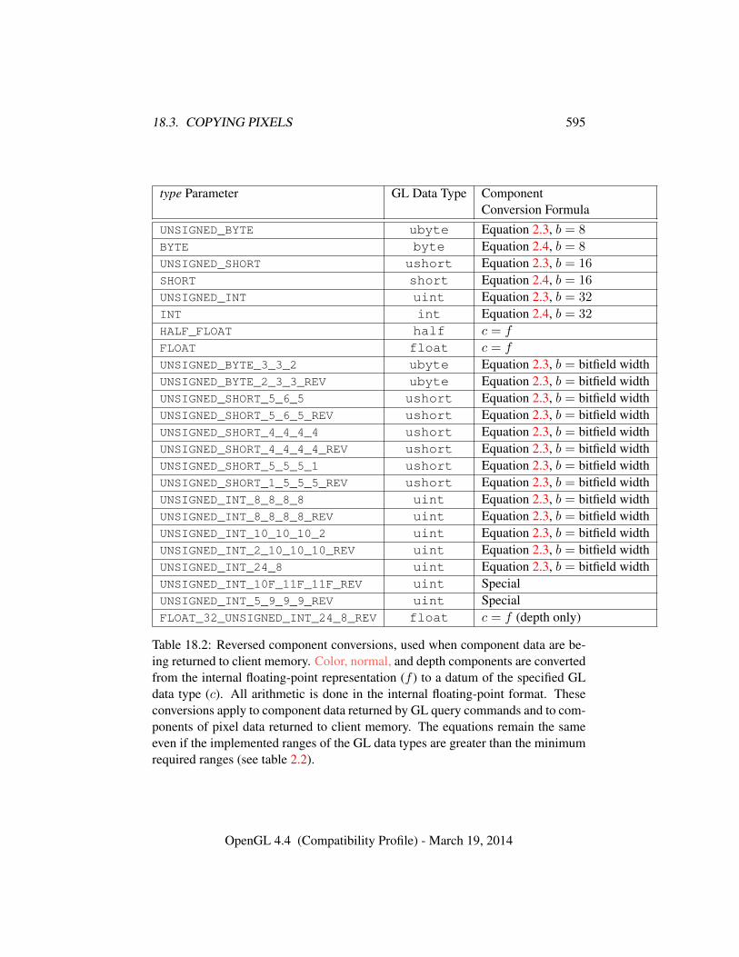
18.3. COPYING PIXELS 595
type Parameter GL Data Type ComponentConversion Formula
UNSIGNED_BYTE ubyte Equation 2.3, b = 8
BYTE byte Equation 2.4, b = 8
UNSIGNED_SHORT ushort Equation 2.3, b = 16
SHORT short Equation 2.4, b = 16
UNSIGNED_INT uint Equation 2.3, b = 32
INT int Equation 2.4, b = 32
HALF_FLOAT half c = f
FLOAT float c = f
UNSIGNED_BYTE_3_3_2 ubyte Equation 2.3, b = bitfield widthUNSIGNED_BYTE_2_3_3_REV ubyte Equation 2.3, b = bitfield widthUNSIGNED_SHORT_5_6_5 ushort Equation 2.3, b = bitfield widthUNSIGNED_SHORT_5_6_5_REV ushort Equation 2.3, b = bitfield widthUNSIGNED_SHORT_4_4_4_4 ushort Equation 2.3, b = bitfield widthUNSIGNED_SHORT_4_4_4_4_REV ushort Equation 2.3, b = bitfield widthUNSIGNED_SHORT_5_5_5_1 ushort Equation 2.3, b = bitfield widthUNSIGNED_SHORT_1_5_5_5_REV ushort Equation 2.3, b = bitfield widthUNSIGNED_INT_8_8_8_8 uint Equation 2.3, b = bitfield widthUNSIGNED_INT_8_8_8_8_REV uint Equation 2.3, b = bitfield widthUNSIGNED_INT_10_10_10_2 uint Equation 2.3, b = bitfield widthUNSIGNED_INT_2_10_10_10_REV uint Equation 2.3, b = bitfield widthUNSIGNED_INT_24_8 uint Equation 2.3, b = bitfield widthUNSIGNED_INT_10F_11F_11F_REV uint SpecialUNSIGNED_INT_5_9_9_9_REV uint SpecialFLOAT_32_UNSIGNED_INT_24_8_REV float c = f (depth only)
Table 18.2: Reversed component conversions, used when component data are be-ing returned to client memory. Color, normal, and depth components are convertedfrom the internal floating-point representation (f ) to a datum of the specified GLdata type (c). All arithmetic is done in the internal floating-point format. Theseconversions apply to component data returned by GL query commands and to com-ponents of pixel data returned to client memory. The equations remain the sameeven if the implemented ranges of the GL data types are greater than the minimumrequired ranges (see table 2.2).
OpenGL 4.4 (Compatibility Profile) - March 19, 2014
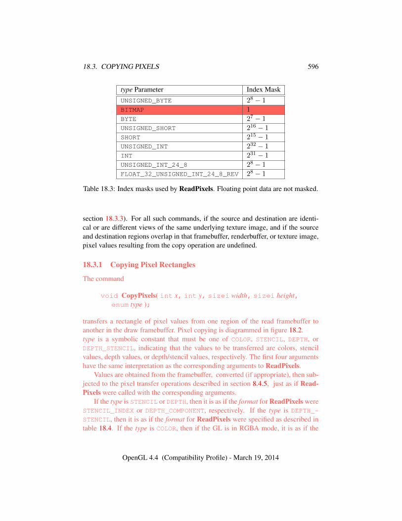
18.3. COPYING PIXELS 596
type Parameter Index MaskUNSIGNED_BYTE 28 − 1
BITMAP 1
BYTE 27 − 1
UNSIGNED_SHORT 216 − 1
SHORT 215 − 1
UNSIGNED_INT 232 − 1
INT 231 − 1
UNSIGNED_INT_24_8 28 − 1
FLOAT_32_UNSIGNED_INT_24_8_REV 28 − 1
Table 18.3: Index masks used by ReadPixels. Floating point data are not masked.
section 18.3.3). For all such commands, if the source and destination are identi-cal or are different views of the same underlying texture image, and if the sourceand destination regions overlap in that framebuffer, renderbuffer, or texture image,pixel values resulting from the copy operation are undefined.
18.3.1 Copying Pixel Rectangles
The command
void CopyPixels( int x, int y, sizei width, sizei height,enum type );
transfers a rectangle of pixel values from one region of the read framebuffer toanother in the draw framebuffer. Pixel copying is diagrammed in figure 18.2.type is a symbolic constant that must be one of COLOR, STENCIL, DEPTH, orDEPTH_STENCIL, indicating that the values to be transferred are colors, stencilvalues, depth values, or depth/stencil values, respectively. The first four argumentshave the same interpretation as the corresponding arguments to ReadPixels.
Values are obtained from the framebuffer, converted (if appropriate), then sub-jected to the pixel transfer operations described in section 8.4.5, just as if Read-Pixels were called with the corresponding arguments.
If the type is STENCIL or DEPTH, then it is as if the format for ReadPixels wereSTENCIL_INDEX or DEPTH_COMPONENT, respectively. If the type is DEPTH_-
STENCIL, then it is as if the format for ReadPixels were specified as described intable 18.4. If the type is COLOR, then if the GL is in RGBA mode, it is as if the
OpenGL 4.4 (Compatibility Profile) - March 19, 2014
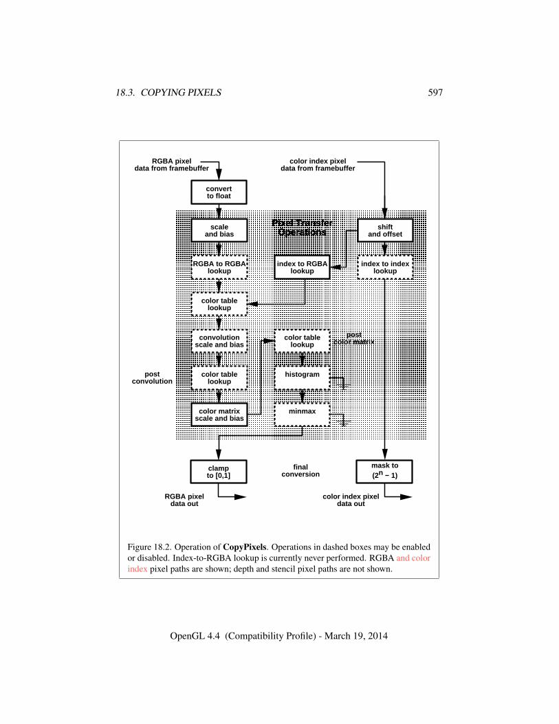
18.3. COPYING PIXELS 597
postconvolution
� � � � � � � � � � � � � � � � � � � � � � � � � � � � � � �� � � � � � � � � � � � � � � � � � � � � � � � � � � � � � �� � � � � � � � � � � � � � � � � � � � � � � � � � � � � � �� � � � � � � � � � � � � � � � � � � � � � � � � � � � � � �� � � � � � � � � � � � � � � � � � � � � � � � � � � � � � �� � � � � � � � � � � � � � � � � � � � � � � � � � � � � � �� � � � � � � � � � � � � � � � � � � � � � � � � � � � � � �� � � � � � � � � � � � � � � � � � � � � � � � � � � � � � �� � � � � � � � � � � � � � � � � � � � � � � � � � � � � � �� � � � � � � � � � � � � � � � � � � � � � � � � � � � � � �� � � � � � � � � � � � � � � � � � � � � � � � � � � � � � �� � � � � � � � � � � � � � � � � � � � � � � � � � � � � � �� � � � � � � � � � � � � � � � � � � � � � � � � � � � � � �� � � � � � � � � � � � � � � � � � � � � � � � � � � � � � �� � � � � � � � � � � � � � � � � � � � � � � � � � � � � � �� � � � � � � � � � � � � � � � � � � � � � � � � � � � � � �� � � � � � � � � � � � � � � � � � � � � � � � � � � � � � �� � � � � � � � � � � � � � � � � � � � � � � � � � � � � � �� � � � � � � � � � � � � � � � � � � � � � � � � � � � � � �� � � � � � � � � � � � � � � � � � � � � � � � � � � � � � �� � � � � � � � � � � � � � � � � � � � � � � � � � � � � � �� � � � � � � � � � � � � � � � � � � � � � � � � � � � � � �� � � � � � � � � � � � � � � � � � � � � � � � � � � � � � �� � � � � � � � � � � � � � � � � � � � � � � � � � � � � � �� � � � � � � � � � � � � � � � � � � � � � � � � � � � � � �� � � � � � � � � � � � � � � � � � � � � � � � � � � � � � �� � � � � � � � � � � � � � � � � � � � � � � � � � � � � � �� � � � � � � � � � � � � � � � � � � � � � � � � � � � � � �
scaleand bias
Pixel TransferOperations
color table lookup
convolution scale a nd bias
histogram
minmax
color table lookup
RGBA to RGBA lookup
shiftand offset
index to index look up
index to RGBA looku p
color table lookup
color matrixscale and bias
postcolor matrix
convertto float
RGBA pixeldata from framebuff er
color index pixeldata from framebuff er
color index pixeldata out
RGBA pixeldata out
clampto [0,1]
mask to(2n − 1)
finalconversion
Figure 18.2. Operation of CopyPixels. Operations in dashed boxes may be enabledor disabled. Index-to-RGBA lookup is currently never performed. RGBA and colorindex pixel paths are shown; depth and stencil pixel paths are not shown.
OpenGL 4.4 (Compatibility Profile) - March 19, 2014
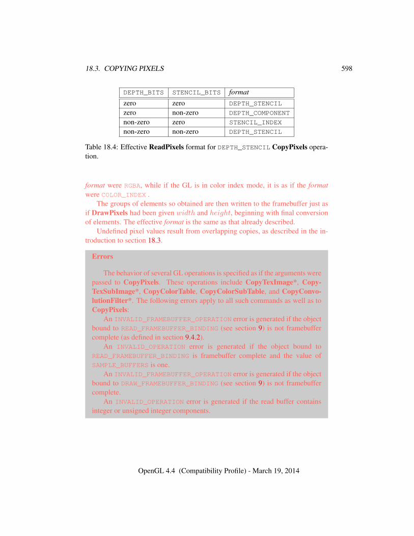
18.3. COPYING PIXELS 598
DEPTH_BITS STENCIL_BITS format
zero zero DEPTH_STENCIL
zero non-zero DEPTH_COMPONENT
non-zero zero STENCIL_INDEX
non-zero non-zero DEPTH_STENCIL
Table 18.4: Effective ReadPixels format for DEPTH_STENCIL CopyPixels opera-tion.
format were RGBA, while if the GL is in color index mode, it is as if the formatwere COLOR_INDEX .
The groups of elements so obtained are then written to the framebuffer just asif DrawPixels had been given width and height, beginning with final conversionof elements. The effective format is the same as that already described.
Undefined pixel values result from overlapping copies, as described in the in-troduction to section 18.3.
Errors
The behavior of several GL operations is specified as if the arguments werepassed to CopyPixels. These operations include CopyTexImage*, Copy-TexSubImage*, CopyColorTable, CopyColorSubTable, and CopyConvo-lutionFilter*. The following errors apply to all such commands as well as toCopyPixels:
An INVALID_FRAMEBUFFER_OPERATION error is generated if the objectbound to READ_FRAMEBUFFER_BINDING (see section 9) is not framebuffercomplete (as defined in section 9.4.2).
An INVALID_OPERATION error is generated if the object bound toREAD_FRAMEBUFFER_BINDING is framebuffer complete and the value ofSAMPLE_BUFFERS is one.
An INVALID_FRAMEBUFFER_OPERATION error is generated if the objectbound to DRAW_FRAMEBUFFER_BINDING (see section 9) is not framebuffercomplete.
An INVALID_OPERATION error is generated if the read buffer containsinteger or unsigned integer components.
OpenGL 4.4 (Compatibility Profile) - March 19, 2014
18.3. COPYING PIXELS 599
18.3.2 Blitting Pixel Rectangles
The command
void BlitFramebuffer( int srcX0, int srcY0, int srcX1,int srcY1, int dstX0, int dstY0, int dstX1, int dstY1,bitfield mask, enum filter );
transfers a rectangle of pixel values from one region of the read framebuffer to an-other in the draw framebuffer. There are some important distinctions from Copy-Pixels, as described below.
mask is zero or the bitwise OR of one or more values indicating which buffersare to be copied. The values are COLOR_BUFFER_BIT, DEPTH_BUFFER_BIT, andSTENCIL_BUFFER_BIT, which are described in section 17.4.3. The pixels corre-sponding to these buffers are copied from the source rectangle bounded by the lo-cations (srcX0, srcY 0) and (srcX1, srcY 1) to the destination rectangle boundedby the locations (dstX0, dstY 0) and (dstX1, dstY 1).
Pixels have half-integer center coordinates. Only pixels whose centers liewithin the destination rectangle are written by BlitFramebuffer. Linear filter sam-pling (see below) may result in pixels outside the source rectangle being read.
If mask is zero, no buffers are copied.When the color buffer is transferred, values are taken from the read buffer of the
read framebuffer and written to each of the draw buffers of the draw framebuffer,just as with CopyPixels.
The actual region taken from the read framebuffer is limited to the intersectionof the source buffers being transferred, which may include the color buffer selectedby the read buffer, the depth buffer, and/or the stencil buffer depending on mask.The actual region written to the draw framebuffer is limited to the intersection ofthe destination buffers being written, which may include multiple draw buffers,the depth buffer, and/or the stencil buffer depending on mask. Whether or not thesource or destination regions are altered due to these limits, the scaling and offsetapplied to pixels being transferred is performed as though no such limits werepresent.
If the source and destination rectangle dimensions do not match, the source im-age is stretched to fit the destination rectangle. filter must be LINEAR or NEAREST,and specifies the method of interpolation to be applied if the image is stretched.LINEAR filtering is allowed only for the color buffer. If the source and destinationdimensions are identical, no filtering is applied. If either the source or destinationrectangle specifies a negative width or height (X1 < X0 or Y 1 < Y 0), the im-age is reversed in the corresponding direction. If both the source and destinationrectangles specify a negative width or height for the same direction, no reversal is
OpenGL 4.4 (Compatibility Profile) - March 19, 2014
18.3. COPYING PIXELS 600
performed. If a linear filter is selected and the rules of LINEAR sampling wouldrequire sampling outside the bounds of a source buffer, it is as though CLAMP_-
TO_EDGE texture sampling were being performed. If a linear filter is selected andsampling would be required outside the bounds of the specified source region, butwithin the bounds of a source buffer, the implementation may choose to clampwhile sampling or not.
If the source and destination buffers are identical, and the source and destina-tion rectangles overlap, the result of the blit operation is undefined.
When values are taken from the read buffer, if FRAMEBUFFER_SRGB is enabledand the value of FRAMEBUFFER_ATTACHMENT_COLOR_ENCODING for the frame-buffer attachment corresponding to the read buffer is SRGB (see section 9.2.3), thered, green, and blue components are converted from the non-linear sRGB colorspace according to equation 8.14.
When values are written to the draw buffers, blit operations bypass most of thefragment pipeline. The only fragment operations which affect a blit are the pixelownership test, the scissor test, and sRGB conversion (see section 17.3.9). Color,depth, and stencil masks (see section 17.4.2) are ignored.
If the read framebuffer is layered (see section 9.8), pixel values are read fromlayer zero. If the draw framebuffer is layered, pixel values are written to layer zero.If both read and draw framebuffers are layered, the blit operation is still performedonly on layer zero.
If a buffer is specified in mask and does not exist in both the read and drawframebuffers, the corresponding bit is silently ignored.
If the color formats of the read and draw buffers do not match, and mask in-cludes COLOR_BUFFER_BIT, pixel groups are converted to match the destinationformat as in CopyPixels. However, no pixel transfer operations are applied, andcolors are clamped only if all draw color buffers have fixed-point components, asif CLAMP_FRAGMENT_COLOR were set to FIXED_ONLY. Format conversion is notsupported for all data types, as described below.
If the read framebuffer is multisampled (its value of SAMPLE_BUFFERS is one)and the draw framebuffer is not (its value of SAMPLE_BUFFERS is zero), the sam-ples corresponding to each pixel location in the source are converted to a singlesample before being written to the destination. filter is ignored. If the source for-mats are integer types or stencil values, a single sample’s value is selected for eachpixel. If the source formats are floating point or normalized types, the sample val-ues for each pixel are resolved in an implementation-dependent manner. If thesource formats are depth values, sample values are resolved in an implementation-dependent manner where the result will be between the minimum and maximumdepth values in the pixel.
OpenGL 4.4 (Compatibility Profile) - March 19, 2014
18.3. COPYING PIXELS 601
If the read framebuffer is not multisampled and the draw framebuffer is mul-tisampled, the value of the source sample is replicated in each of the destinationsamples.
If both the read and draw framebuffers are multisampled, and their respec-tive values of SAMPLES are identical, the samples are copied without modifica-tion (other than possible format conversion) from the read framebuffer to the drawframebuffer. Note that the samples in the draw buffer are not guaranteed to be atthe same sample location as the read buffer, so rendering using this newly createdbuffer can potentially have geometry cracks or incorrect antialiasing. This mayoccur if the sizes of the framebuffers do not match or if the source and destinationrectangles are not defined with the same (X0, Y 0) and (X1, Y 1) bounds.
Undefined pixel values result from overlapping copies, as described in the in-troduction to section 18.3.
Errors
An INVALID_VALUE error is generated if mask contains any bits otherthan COLOR_BUFFER_BIT, DEPTH_BUFFER_BIT, or STENCIL_BUFFER_-
BIT.An INVALID_ENUM error is generated if filter is not LINEAR or NEAREST.An INVALID_OPERATION error is generated if mask includes DEPTH_-
BUFFER_BIT or STENCIL_BUFFER_BIT, and filter is not NEAREST.An INVALID_FRAMEBUFFER_OPERATION error is generated if either the
read framebuffer or the draw framebuffer is not framebuffer complete (sec-tion 9.4.2).
An INVALID_OPERATION error is generated if mask includes DEPTH_-BUFFER_BIT or STENCIL_BUFFER_BIT, and the source and destinationdepth and stencil buffer formats do not match.
An INVALID_OPERATION error is generated if filter is LINEAR and theread buffer contains integer data.
An INVALID_OPERATION error is generated if either of the read or drawframebuffers is multisampled, and the dimensions of the source and destina-tion rectangles provided to BlitFramebuffer are not identical.
An INVALID_OPERATION error is generated if both the read and drawframebuffers are multisampled, and their respective values of SAMPLES arenot identical.
An INVALID_OPERATION error is generated if format conversions are notsupported, which occurs under any of the following conditions:• The read buffer contains fixed-point or floating-point values and any
draw buffer contains neither fixed-point nor floating-point values.
OpenGL 4.4 (Compatibility Profile) - March 19, 2014
18.3. COPYING PIXELS 602
• The read buffer contains unsigned integer values and any draw bufferdoes not contain unsigned integer values.
• The read buffer contains signed integer values and any draw buffer doesnot contain signed integer values.
18.3.3 Copying Between Images
The command
void CopyImageSubData( uint srcName, enum srcTarget,int srcLevel, int srcX, int srcY, int srcZ,uint dstName, enum dstTarget, int dstLevel, int dstX,int dstY, int dstZ, sizei srcWidth, sizei srcHeight,sizei srcDepth );
may be used to copy a region of texel data between two image objects. An imageobject may be either a texture or a renderbuffer.
CopyImageSubData does not perform general-purpose conversions such asscaling, resizing, blending, color-space, or format conversions. It should be con-sidered to operate in a manner similar to a CPU memcpy. CopyImageSubDatacan copy between images with different internal formats, provided the formats arecompatible.
CopyImageSubData also allows copying between certain types of compressedand uncompressed internal formats as described in table 18.5. This copy does notperform on-the-fly compression or decompression. When copying from an un-compressed internal format to a compressed internal format, each texel of uncom-pressed data becomes a single block of compressed data. When copying from acompressed internal format to an uncompressed internal format, a block of com-pressed data becomes a single texel of uncompressed data. The texel size of theuncompressed format must be the same size the block size of the compressed for-mats. Thus it is permitted to copy between a 128-bit uncompressed format anda compressed format which uses 8-bit 4 × 4 blocks, or between a 64-bit uncom-pressed format and a compressed format which uses 4-bit 4× 4 blocks.
The source object is identified by srcName and srcTarget. Similarly the des-tination object is identified by dstName and dstTarget. The interpretation of thename depends on the value of the corresponding target parameter. If the targetparameter is RENDERBUFFER, the name is interpreted as the name of a render-buffer object. If the target parameter is a texture target, the name is interpreted asa texture object. All non-proxy texture targets are accepted, with the exception ofTEXTURE_BUFFER and the cubemap face selectors described in table 8.26.
OpenGL 4.4 (Compatibility Profile) - March 19, 2014
18.3. COPYING PIXELS 603
srcLevel and dstLevel identify the source and destination level of detail. Fortextures, this must be a valid level of detail in the texture object. For renderbuffers,this value must be zero.
srcX, srcY, and srcZ specify the lower left texel coordinates of a srcWidth-wideby srcHeight-high by srcDepth-deep rectangular subregion of the source texel ar-ray. Negative values of srcX, srcY, and srcZ correspond to the coordinates of bordertexels, addressed as in figure 8.3. Similarly, dstX, dstY and dstZ specify the coordi-nates of a subregion of the destination texel array. The source and destination sub-regions must be contained entirely within the specified level of the correspondingimage objects. The dimensions are always specified in texels, even for compressedtexture formats. But it should be noted that if only one of the source and destina-tion textures is compressed then the number of texels touched in the compressedimage will be a factor of the block size larger than in the uncompressed image.
Slices of a TEXTURE_1D_ARRAY, TEXTURE_2D_ARRAY, TEXTURE_CUBE_-MAP_ARRAY TEXTURE_3D and faces of TEXTURE_CUBE_MAP are all compatibleprovided they share a compatible internal format, and multiple slices or faces maybe copied between these objects with a single call by specifying the starting slicewith srcZ and dstZ, and the number of slices to be copied with srcDepth. Cube-map textures always have six faces which are selected by a zero-based face index,according to the order specified in table 8.26.
For the purposes of CopyImageSubData, two internal formats are consideredcompatible if any of the following conditions are met:
• the formats are the same
• the formats are considered compatible according to the compatibility rulesused for texture views as defined in section 8.18. In particular, if both in-ternal formats are listed in the same entry of table 8.29, they are consideredcompatible
• one format is compressed and the other is uncompressed and table 18.5 liststhe two formats in the same row.
Undefined pixel values result from overlapping copies, as described in the in-troduction to section 18.3.
Errors
An INVALID_OPERATION error is generated if the texel size of the un-compressed image is not equal to the block size of the compressed image.
An INVALID_ENUM error is generated if either target is notRENDERBUFFER or a valid non-proxy texture target; is TEXTURE_BUFFER or
OpenGL 4.4 (Compatibility Profile) - March 19, 2014

18.3. COPYING PIXELS 604
Texel / Uncompressed CompressedBlock Size internal format internal format128-bit RGBA32UI,
RGBA32I, RGBA32FCOMPRESSED_RG_RGTC2, COMPRESSED_-
SIGNED_RG_RGTC2, COMPRESSED_-
RGBA_BPTC_UNORM, COMPRESSED_-
SRGB_ALPHA_BPTC_UNORM,COMPRESSED_RGB_BPTC_SIGNED_FLOAT,COMPRESSED_RGB_BPTC_UNSIGNED_-
FLOAT
64-bit RGBA16F, RG32F,RGBA16UI, RG32UI,RGBA16I, RG32I,RGBA16, RGBA16_-
SNORM
COMPRESSED_RED_RGTC1,COMPRESSED_SIGNED_RED_RGTC1
Table 18.5: Compatible internal formats for copying between compressed and un-compressed internal formats with CopyImageSubData. Formats in the same rowcan be copied between each other.
one of the cubemap face selectors described in table 8.26; or if the target doesnot match the type of the object.
An INVALID_OPERATION error is generated if either object is a textureand the texture is not complete (as defined in section 8.17), if the source anddestination internal formats are not compatible (see below), or if the numberof samples do not match.
An INVALID_VALUE error is generated if either name does not correspondto a valid renderbuffer or texture object according to the corresponding targetparameter.
An INVALID_VALUE error is generated if srcLevel and dstLevel are notvalid levels for the corresponding images.
An INVALID_VALUE error is generated if srcWidth, srcHeight, or sr-cDepth is negative.
An INVALID_VALUE error is generated if the dimensions of either sub-region exceeds the boundaries of the corresponding image object, or if theimage format is compressed and the dimensions of the subregion fail to meetthe alignment constraints of the format.
An INVALID_OPERATION error is generated if the formats are not com-patible.
OpenGL 4.4 (Compatibility Profile) - March 19, 2014
18.4. PIXEL DRAW AND READ STATE 605
18.4 Pixel Draw and Read State
The state required for pixel operations consists of the parameters that are set withPixelStore, PixelTransfer, and PixelMap. This state has been summarized intables 8.1 and 18.1, 8.2, and 8.3, respectively Additional state includes the cur-rent raster position (section 14.7), and a three-valued integer controlling clampingduring final conversion. The initial value of read color clamping is FIXED_ONLY.State set with PixelStore is GL client state.
OpenGL 4.4 (Compatibility Profile) - March 19, 2014
Chapter 19
Compute Shaders
In addition to graphics-oriented shading operations such as vertex, tessellation,geometry and fragment shading, generic computation may be performed by theGL through the use of compute shaders. The compute pipeline is a form of single-stage machine that runs generic shaders. Compute shaders are created as describedin section 7.1 using a type parameter of COMPUTE_SHADER. They are attached toand used in program objects as described in section 7.3.
Compute workloads are formed from groups of work items called work groupsand processed by the executable code for a compute program. A work group is acollection of shader invocations that execute the same code, potentially in parallel.An invocation within a work group may share data with other members of the sameworkgroup through shared variables (see section 4.3.8(“Shared Variables”) of theOpenGL Shading Language Specification) and issue memory and control barriersto synchronize with other members of the same work group. One or more workgroups is launched by calling:
void DispatchCompute( uint num groups x,uint num groups y, uint num groups z );
Each work group is processed by the active program object for the computeshader stage. The active program for the compute shader stage will be determinedin the same manner as the active program for other pipeline stages, as describedin section 7.3. While the individual shader invocations within a work group areexecuted as a unit, work groups are executed completely independently and inunspecified order.
num groups x, num groups y and num groups z specify the number of localwork groups that will be dispatched in the X, Y and Z dimensions, respectively.
606
607
The built-in vector variable gl_NumWorkGroups will be initialized with the con-tents of the num groups x, num groups y and num groups z parameters. The max-imum number of work groups that may be dispatched at one time may be deter-mined by calling GetIntegeri v with target set to MAX_COMPUTE_WORK_GROUP_-COUNT and index set to zero, one, or two, representing the X, Y, and Z dimensionsrespectively. If the work group count in any dimension is zero, no work groupsare dispatched.
The local work size in each dimension are specified at compile time usingan input layout qualifier in one or more of the compute shaders attached to theprogram (see section 4.4.1.4(“Compute Shader Inputs”) of the OpenGL ShadingLanguage Specification). After the program has been linked, the local work groupsize of the program may be queried by calling GetProgramiv with pname set toCOMPUTE_WORK_GROUP_SIZE, as described in section 7.13.
The maximum size of a local work group may be determined by calling Get-Integeri v with target set to MAX_COMPUTE_WORK_GROUP_SIZE and index set to0, 1, or 2 to retrieve the maximum work size in the X, Y and Z dimension, respec-tively. Furthermore, the maximum number of invocations in a single local workgroup (i.e., the product of the three dimensions) may be determined by callingGetIntegerv with pname set to MAX_COMPUTE_WORK_GROUP_INVOCATIONS.
Errors
An INVALID_OPERATION error is generated if there is no active programfor the compute shader stage.
An INVALID_VALUE error is generated if any of num groups x, num -groups y and num groups z are greater than or equal to the maximum workgroup count for the corresponding dimension.
An INVALID_OPERATION error is generated if program is the name of aprogram that has not been successfully linked, or of a linked program objectthat contains no compute shaders.
The command
void DispatchComputeIndirect( intptr indirect );
is equivalent to calling DispatchCompute with num groups x, num groups y andnum groups z initialized with the three uint values contained in the buffer cur-rently bound to the DISPATCH_INDIRECT_BUFFER binding at an offset, in basicmachine units, specified in indirect. If any of num groups x, num groups y ornum groups z is greater than the value of MAX_COMPUTE_WORK_GROUP_COUNTfor the corresponding dimension then the results are undefined.
OpenGL 4.4 (Compatibility Profile) - March 19, 2014
19.1. COMPUTE SHADER VARIABLES 608
Errors
An INVALID_OPERATION error is generated if there is no active programfor the compute shader stage.
An INVALID_VALUE error is generated if indirect is negative or is not amultiple of the size, in basic machine units, of uint.
An INVALID_OPERATION error is generated if the command wouldsource data beyond the end of the buffer object.
An INVALID_OPERATION error is generated if zero is bound to theDRAW_INDIRECT_BUFFER binding.
19.1 Compute Shader Variables
Compute shaders can access variables belonging to the current program object.Limits on uniform storage and methods for manipulating uniforms are described insection 7.6.
There is a limit to the total size of all variables declared as shared in a singleprogram object. This limit, expressed in units of basic machine units, may bequeried as the value of MAX_COMPUTE_SHARED_MEMORY_SIZE.
OpenGL 4.4 (Compatibility Profile) - March 19, 2014
Chapter 20
Debug Output
Application developers can obtain details about errors, undefined behavior,implementation-dependent performance warnings, or other useful hints from theGL in the form of debug output.
Debug output is communicated through a stream of debug messages that aregenerated as GL commands are executed. The application can choose to receivethese messages either through a callback routine, or by querying for them from amessage log.
Controls are provided for disabling messages that the application does not careabout, and for inserting application-generated messages into the stream.
Different levels of debug output may be provided, depending on how the con-text was created. If the context is not a debug context1 (e.g. if it was created withoutthe CONTEXT_FLAG_DEBUG_BIT set in the CONTEXT_FLAGS state, as describedin section 22.2), then the GL may optionally not generate any debug messages, butthe commands described in this chapter will otherwise operate without error.
Debug output functionality is enabled or disabled by calling Enable or Disablewith target DEBUG_OUTPUT. If the context is a debug context (if it was created withthe CONTEXT_FLAG_DEBUG_BIT set in CONTEXT_FLAGS) then the initial value ofDEBUG_OUTPUT is TRUE; otherwise the initial value is FALSE.
In a debug context, if DEBUG_OUTPUT is disabled the GL will not generate anydebug output logs or callbacks. Enabling DEBUG_OUTPUT again will enable fulldebug output functionality.
In a non-debug context, if DEBUG_OUTPUT is later enabled, the level of debugoutput logging is defined by the GL implementation, which may have zero debug
1Debug contexts are specified at context creation time, using window-system binding APIssuch as those specified in the GLX_ARB_create_context and WGL_ARB_create_-context extensions for GLX and WGL, respectively.
609
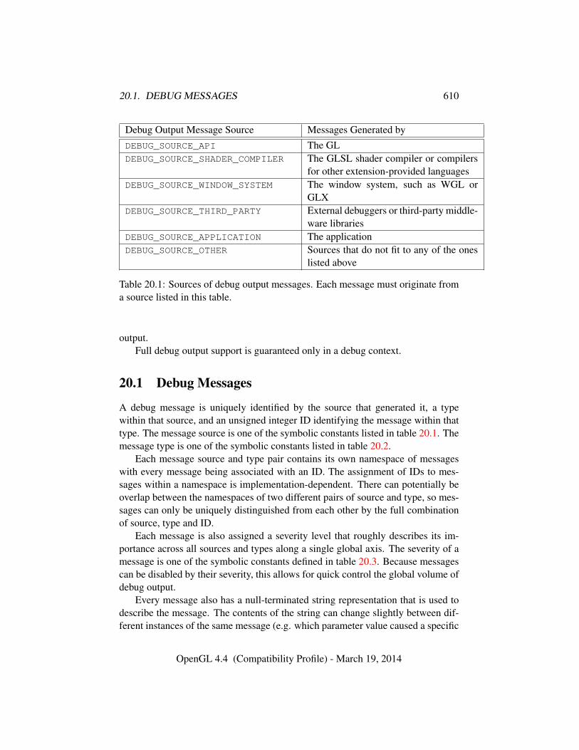
20.1. DEBUG MESSAGES 610
Debug Output Message Source Messages Generated byDEBUG_SOURCE_API The GLDEBUG_SOURCE_SHADER_COMPILER The GLSL shader compiler or compilers
for other extension-provided languagesDEBUG_SOURCE_WINDOW_SYSTEM The window system, such as WGL or
GLXDEBUG_SOURCE_THIRD_PARTY External debuggers or third-party middle-
ware librariesDEBUG_SOURCE_APPLICATION The applicationDEBUG_SOURCE_OTHER Sources that do not fit to any of the ones
listed above
Table 20.1: Sources of debug output messages. Each message must originate froma source listed in this table.
output.Full debug output support is guaranteed only in a debug context.
20.1 Debug Messages
A debug message is uniquely identified by the source that generated it, a typewithin that source, and an unsigned integer ID identifying the message within thattype. The message source is one of the symbolic constants listed in table 20.1. Themessage type is one of the symbolic constants listed in table 20.2.
Each message source and type pair contains its own namespace of messageswith every message being associated with an ID. The assignment of IDs to mes-sages within a namespace is implementation-dependent. There can potentially beoverlap between the namespaces of two different pairs of source and type, so mes-sages can only be uniquely distinguished from each other by the full combinationof source, type and ID.
Each message is also assigned a severity level that roughly describes its im-portance across all sources and types along a single global axis. The severity of amessage is one of the symbolic constants defined in table 20.3. Because messagescan be disabled by their severity, this allows for quick control the global volume ofdebug output.
Every message also has a null-terminated string representation that is used todescribe the message. The contents of the string can change slightly between dif-ferent instances of the same message (e.g. which parameter value caused a specific
OpenGL 4.4 (Compatibility Profile) - March 19, 2014
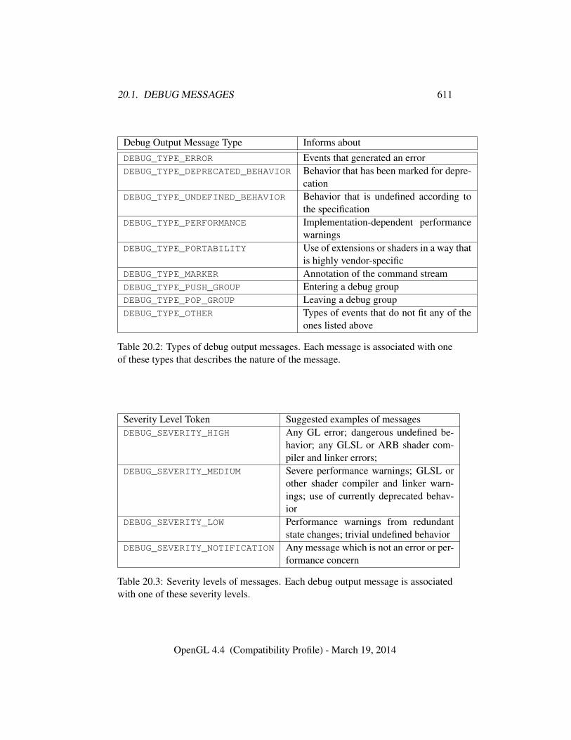
20.1. DEBUG MESSAGES 611
Debug Output Message Type Informs aboutDEBUG_TYPE_ERROR Events that generated an errorDEBUG_TYPE_DEPRECATED_BEHAVIOR Behavior that has been marked for depre-
cationDEBUG_TYPE_UNDEFINED_BEHAVIOR Behavior that is undefined according to
the specificationDEBUG_TYPE_PERFORMANCE Implementation-dependent performance
warningsDEBUG_TYPE_PORTABILITY Use of extensions or shaders in a way that
is highly vendor-specificDEBUG_TYPE_MARKER Annotation of the command streamDEBUG_TYPE_PUSH_GROUP Entering a debug groupDEBUG_TYPE_POP_GROUP Leaving a debug groupDEBUG_TYPE_OTHER Types of events that do not fit any of the
ones listed above
Table 20.2: Types of debug output messages. Each message is associated with oneof these types that describes the nature of the message.
Severity Level Token Suggested examples of messagesDEBUG_SEVERITY_HIGH Any GL error; dangerous undefined be-
havior; any GLSL or ARB shader com-piler and linker errors;
DEBUG_SEVERITY_MEDIUM Severe performance warnings; GLSL orother shader compiler and linker warn-ings; use of currently deprecated behav-ior
DEBUG_SEVERITY_LOW Performance warnings from redundantstate changes; trivial undefined behavior
DEBUG_SEVERITY_NOTIFICATION Any message which is not an error or per-formance concern
Table 20.3: Severity levels of messages. Each debug output message is associatedwith one of these severity levels.
OpenGL 4.4 (Compatibility Profile) - March 19, 2014
20.2. DEBUG MESSAGE CALLBACK 612
GL error to occur). The format of a message string is left as implementation-dependent, although it should at least represent a concise description of the eventthat caused the message to be generated. Messages with different IDs should alsohave sufficiently distinguishable string representations to warrant their separation.
The lengths of all messages, including their null terminators, is guaranteedto be less or equal to the value of the implementation-dependent constant MAX_-DEBUG_MESSAGE_LENGTH.
Messages can be either enabled or disabled. Messages that are disabled willnot be generated. All messages are initially enabled unless their assigned severityis DEBUG_SEVERITY_LOW. The enabled state of messages can be changed usingthe command DebugMessageControl.
20.2 Debug Message Callback
Applications can provide a callback function for receiving debug messages usingthe command
void DebugMessageCallback( DEBUGPROC callback, constvoid *userParam );
with callback storing the address of the callback function. callback must be afunction whose prototype is of the form
void callback( enum source, enum type, uint id,enum severity, sizei length, const char *message,const void *userParam );
Additionally, callback must be declared with the same platform-dependentcalling convention used in the definition of the type DEBUGPROC. Anything elsewill result in undefined behavior.
Only one debug callback can be specified for the current context, and furthercalls overwrite the previous callback. Specifying NULL as the value of callbackclears the current callback and disables message output through callbacks. Appli-cations can provide user-specified data through the pointer userParam. The contextwill store this pointer and will include it as one of the parameters in each call to thecallback function.
If the application has specified a callback function for receiving debug out-put, the implementation will call that function whenever any enabled message isgenerated. The source, type, ID, and severity of the message are specified by theDEBUGPROC parameters source, type, id, and severity, respectively. The string
OpenGL 4.4 (Compatibility Profile) - March 19, 2014
20.3. DEBUG MESSAGE LOG 613
representation of the message is stored in message and its length (excluding thenull-terminator) is stored in length. The parameter userParam is the user-specifiedparameter that was given when calling DebugMessageCallback.
Applications that specify a callback function must be aware of certain specialconditions when executing code inside a callback when it is called by the GL,regardless of the debug source.
The memory for message is owned and managed by the GL, and should onlybe considered valid for the duration of the function call.
The behavior of calling any GL or window system function from within thecallback function is undefined and may lead to program termination.
Care must also be taken in securing debug callbacks for use with asynchronousdebug output by multi-threaded GL implementations. Section 20.8 describes thisin further detail.
If DEBUG_OUTPUT is disabled, then the GL will not call the callback function.
20.3 Debug Message Log
If DEBUG_CALLBACK_FUNCTION is NULL, then debug messages are instead storedin an internal message log up to some maximum number of messages as definedby the value of MAX_DEBUG_LOGGED_MESSAGES.
Each context stores its own message log and will only store messages gener-ated by commands operating in that context. If the message log fills up, then anysubsequently generated messages will not be placed in the log until the messagelog is cleared, and will instead be discarded.
Applications can query the number of messages currently in the log by obtain-ing the value of DEBUG_LOGGED_MESSAGES, and the string length (including itsnull terminator) of the oldest message in the log through the value of DEBUG_-NEXT_LOGGED_MESSAGE_LENGTH.
To fetch message data stored in the log, the command GetDebugMessageLogcan be used.
If DEBUG_CALLBACK_FUNCTION is not NULL, no generated messages will bestored in the log but will instead be passed to the debug callback routine as de-scribed in section 20.2.
If DEBUG_OUTPUT is disabled, then no messages are added to the message log.
20.4 Controlling Debug Messages
Applications can control the volume of debug output in the active debug group (seesection 20.6) by disabling specific groups of messages with the command:
OpenGL 4.4 (Compatibility Profile) - March 19, 2014
20.4. CONTROLLING DEBUG MESSAGES 614
void DebugMessageControl( enum source, enum type,enum severity, sizei count, const uint *ids,boolean enabled );
If enabled is TRUE, the referenced subset of messages will be enabled. IfFALSE, then those messages will be disabled.
This command can reference different subsets of messages by first consideringthe set of all messages, and filtering out messages based on the following ways:
• If source, type, or severity is DONT_CARE, then messages from all sources,of all types, or of all severities are referenced respectively.
• When values other than DONT_CARE are specified, all messages whosesource, type, or severity match the specified source, type, or severity respec-tively will be referenced.
• If count is greater than zero, then ids is an array of count message IDs for thespecified combination of source and type. In this case, source or type mustnot be DONT_CARE, and severity must be DONT_CARE,
Unrecognized message IDs in ids are ignored. If count is zero, the value ifids is ignored.
Although messages are grouped into an implicit hierarchy by their sources andtypes, there is no explicit per-source, per-type or per-severity enabled state. Instead,the enabled state is stored individually for each message. There is no differencebetween disabling all messages from one source in a single call, and individuallydisabling all messages from that source using their types and IDs.
If DEBUG_OUTPUT is disabled, then it is as if messages of every source, type,or severity are disabled.
Errors
An INVALID_ENUM error is generated if any of source, type, and severityis neither DONT_CARE nor one of the symbols from, respectively, tables 20.1,20.2, and 20.3.
An INVALID_VALUE error is generated if count is negative,An INVALID_OPERATION error is generated if count is greater than zero
and either source or type is DONT_CARE, or severity is not DONT_CARE.
OpenGL 4.4 (Compatibility Profile) - March 19, 2014
20.5. EXTERNALLY GENERATED MESSAGES 615
20.5 Externally Generated Messages
To support applications and third-party libraries generating their own messages,such as ones containing timestamp information or signals about specific rendersystem events, the following function can be called
void DebugMessageInsert( enum source, enum type, uint id,enum severity, int length, const char *buf );
The value of id specifies the ID for the message and severity indicates its sever-ity level as defined by the caller. The string buf contains the string representationof the message. The parameter length contains the number of characters in buf. Iflength is negative, it is implied that buf contains a null terminated string.
Errors
If DEBUG_OUTPUT is disabled, then calls to DebugMessageInsert are dis-carded, but do not generate an error.
An INVALID_ENUM error is generated if type is not one of the values fromtable 20.2, or if source is not DEBUG_SOURCE_APPLICATION or DEBUG_-SOURCE_THIRD_PARTY.
An INVALID_VALUE error is generated if severity is not one of the severitylevels listed in table 20.3.
An INVALID_VALUE error is generated if the number of characters in buf,excluding the null terminator when length is negative, is not less than the valueof MAX_DEBUG_MESSAGE_LENGTH.
20.6 Debug Groups
Debug groups provide a method for annotating a command stream with discretegroups of commands using a descriptive text. Debug output messages, either gener-ated by the implementation or inserted by the application with DebugMessageIn-sert are written to the active debug group (the top of the debug group stack). Debuggroups are strictly hierarchical. Their sequences may be nested within other debuggroups but can not overlap. If no debug group has been pushed by the applicationthen the active debug group is the default debug group.
The command
void PushDebugGroup( enum source, uint id, sizei length,const char *message );
OpenGL 4.4 (Compatibility Profile) - March 19, 2014
20.6. DEBUG GROUPS 616
pushes a debug group described by the string message into the command stream.The value of id specifies the ID of messages generated. The parameter lengthcontains the number of characters in message. If length is negative, it is im-plied that message contains a null terminated string. The message has the spec-ified source and id, type DEBUG_TYPE_PUSH_GROUP, and severity DEBUG_-
SEVERITY_NOTIFICATION. The GL will put a new debug group on top of thedebug group stack which inherits control of the volume of debug output of the de-bug group previously residing on the top of the debug group stack. Because debuggroups are strictly hierarchical, any additional control of the debug output volumewill only apply within the active debug group and the debug groups pushed on topof the active debug group.
Errors
An INVALID_ENUM error is generated if the value of source is neitherDEBUG_SOURCE_APPLICATION nor DEBUG_SOURCE_THIRD_PARTY.
An INVALID_VALUE error is generated if length is negative and the num-ber of characters in message, excluding the null-terminator, is not less than thevalue of MAX_DEBUG_MESSAGE_LENGTH.
A STACK_OVERFLOW error is generated if PushDebugGroup is called andthe stack contains the value of MAX_DEBUG_GROUP_STACK_DEPTHminus oneelements.
The command
void PopDebugGroup( void );
pops the active debug group. After popping a debug group, the GL will alsogenerate a debug output message describing its cause based on the messagestring, the source, and an id submitted to the associated PushDebugGroup com-mand. DEBUG_TYPE_PUSH_GROUP and DEBUG_TYPE_POP_GROUP share a sin-gle namespace for message id. severity has the value DEBUG_SEVERITY_-
NOTIFICATION and type has the value DEBUG_TYPE_POP_GROUP. Popping a de-bug group restores the debug output volume control of the parent debug group.
Errors
A STACK_UNDERFLOW error is generated if PopDebugGroup is called andonly the default debug group is on the stack.
OpenGL 4.4 (Compatibility Profile) - March 19, 2014
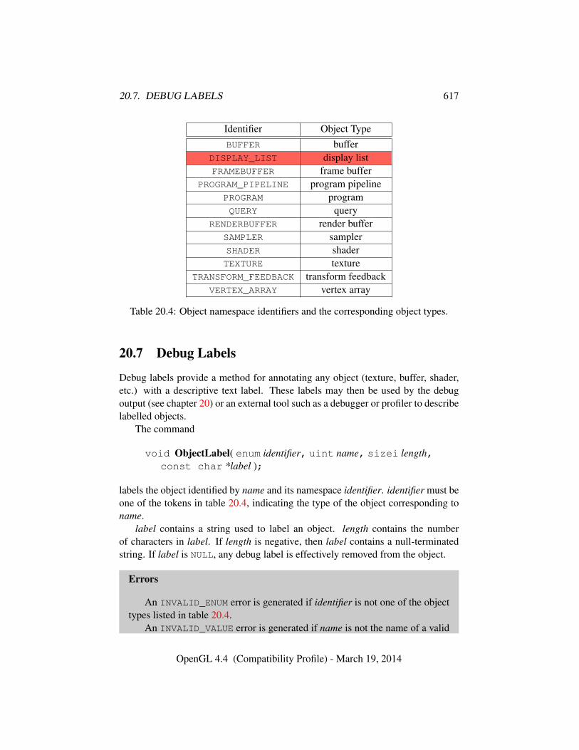
20.7. DEBUG LABELS 617
Identifier Object TypeBUFFER buffer
DISPLAY_LIST display listFRAMEBUFFER frame buffer
PROGRAM_PIPELINE program pipelinePROGRAM programQUERY query
RENDERBUFFER render bufferSAMPLER samplerSHADER shaderTEXTURE texture
TRANSFORM_FEEDBACK transform feedbackVERTEX_ARRAY vertex array
Table 20.4: Object namespace identifiers and the corresponding object types.
20.7 Debug Labels
Debug labels provide a method for annotating any object (texture, buffer, shader,etc.) with a descriptive text label. These labels may then be used by the debugoutput (see chapter 20) or an external tool such as a debugger or profiler to describelabelled objects.
The command
void ObjectLabel( enum identifier, uint name, sizei length,const char *label );
labels the object identified by name and its namespace identifier. identifier must beone of the tokens in table 20.4, indicating the type of the object corresponding toname.
label contains a string used to label an object. length contains the numberof characters in label. If length is negative, then label contains a null-terminatedstring. If label is NULL, any debug label is effectively removed from the object.
Errors
An INVALID_ENUM error is generated if identifier is not one of the objecttypes listed in table 20.4.
An INVALID_VALUE error is generated if name is not the name of a valid
OpenGL 4.4 (Compatibility Profile) - March 19, 2014
20.8. ASYNCHRONOUS AND SYNCHRONOUS DEBUG OUTPUT 618
object of the type specified by identifier.An INVALID_VALUE error is generated if the number of characters in la-
bel, excluding the null terminator when length is negative, is not less than thevalue of MAX_LABEL_LENGTH.
The command
void ObjectPtrLabel( void *ptr, sizei length, constchar *label );
labels the sync object identified by ptr. length and label match the correspondingarguments of ObjectLabel.
Errors
An INVALID_VALUE error is generated if ptr is not the name of a syncobject.
An INVALID_VALUE error is generated if the number of characters in la-bel, excluding the null terminator when length is negative, is not less than thevalue of MAX_LABEL_LENGTH.
A label is part of the state of the object to which it is associated. The initialstate of an object’s label is the empty string. Labels need not be unique.
20.8 Asynchronous and Synchronous Debug Output
The behavior of how and when the GL driver is allowed to generate debug mes-sages, and subsequently either call back to the application or place the message inthe debug message log, is affected by the state DEBUG_OUTPUT_SYNCHRONOUS.This state can be modified by the Enable and Disable commands. Its initial valueis FALSE.
When DEBUG_OUTPUT_SYNCHRONOUS is disabled, the driver is optionally al-lowed to concurrently call the debug callback routine from potentially multiplethreads, including threads that the context that generated the message is not cur-rently bound to. The implementation may also call the callback routine asyn-chronously after the GL command that generated the message has already returned.The application is fully responsible for ensuring thread safety due to debug call-backs under these circumstances. In this situation the userParam value may behelpful in identifying which application thread’s command originally generatedthe debug callback.
OpenGL 4.4 (Compatibility Profile) - March 19, 2014
20.9. DEBUG OUTPUT QUERIES 619
When DEBUG_OUTPUT_SYNCHRONOUS is enabled, the driver guarantees syn-chronous calls to the callback routine by the context. When synchronous callbacksare enabled, all calls to the callback routine will be made by the thread that ownsthe current context; all such calls will be made serially by the current context; andeach call will be made before the GL command that generated the debug messageis allowed to return.
When no callback is specified and DEBUG_OUTPUT_SYNCHRONOUS is disabled,the driver can still asynchronously place messages in the debug message log, evenafter the context thread has returned from the GL function that generated thosemessages. When DEBUG_OUTPUT_SYNCHRONOUS is enabled, the driver guaran-tees that all messages are added to the log before the GL function returns.
Enabling synchronous debug output greatly simplifies the responsibilities ofthe application for making its callback functions thread-safe, but may potentiallyresult in drastically reduced driver performance.
The DEBUG_OUTPUT_SYNCHRONOUS only guarantees intra-context synchro-nization for the callbacks of messages generated by that context, and does notguarantee synchronization across multiple contexts. If multiple contexts are con-currently used by the application, it is allowed for those contexts to also concur-rently call their designated callbacks, and the application is responsible for han-dling thread safety in that situation even if DEBUG_OUTPUT_SYNCHRONOUS is en-abled in all contexts.
20.9 Debug Output Queries
Pointers set with debug output commands are queried with the generic GetPoint-erv command (see section 22.2). pnames DEBUG_CALLBACK_FUNCTION andDEBUG_CALLBACK_USER_PARAM respectively query the current callback functionand the user parameter to that function set with DebugMessageCallback.
When no debug callback is set, debug messages are stored in a debug messagelog as described in section 20.3. Messages can be queried from the log by calling
uint GetDebugMessageLog( uint count, sizei bufSize,enum *sources, enum *types, uint *ids, enum *severities,sizei *lengths, char *messageLog );
GetDebugMessageLog fetches a maximum of count messages from the mes-sage log, and will return the number of messages successfully fetched.
Messages will be fetched from the log in order of oldest to newest. Thosemessages that were fetched will be removed from the log.
OpenGL 4.4 (Compatibility Profile) - March 19, 2014
20.9. DEBUG OUTPUT QUERIES 620
The sources, types, severities, IDs, and string lengths of fetched messages willbe stored in the application-provided arrays sources, types, severities, ids, andlengths, respectively. The application is responsible for allocating enough spacefor each array to hold up to count elements. The string representations of allfetched messages are stored in the messageLog array. If multiple messages arefetched, their strings are concatenated into the same messageLog array and willbe separated by single null terminators. The last string in the array will also benull-terminated. The maximum size of messageLog, including the space used byall null terminators, is given by bufSize.
If a message’s string, including its null terminator, can not fully fit within themessageLog array’s remaining space, then that message and any subsequent mes-sages will not be fetched and will remain in the log. The string lengths stored inthe array lengths include the space for the null terminator of each string.
Any or all of the arrays sources, types, ids, severities, lengths and messageLogcan also be NULL pointers, which causes attributes for such arrays to be discardedwhen messages are fetched. However, those messages will still be removed fromthe log. Thus to simply delete up to count messages from the message log while ig-noring their attributes, the application can call GetDebugMessageLog with NULL
pointers for all attribute arrays.If the context is not a debug context, then the GL can opt to never add messages
to the message log, so that GetDebugMessageLog will always return zero.
Errors
An INVALID_VALUE error is generated if bufSize is negative and mes-sageLog is not NULL.
The command
void GetObjectLabel( enum identifier, uint name,sizei bufSize, sizei *length, char *label );
returns in label the string labelling an object. identifier and name specify thenamespace and name of the object, and match the corresponding arguments ofObjectLabel (see section 20.7).
label will be null-terminated. The actual number of characters written intolabel, excluding the null terminator, is returned in length. If length is NULL, nolength is returned. The maximum number of characters that may be written intolabel, including the null terminator, is specified by bufSize. If no debug label wasspecified for the object then label will contain a null-terminated empty string, and
OpenGL 4.4 (Compatibility Profile) - March 19, 2014
20.9. DEBUG OUTPUT QUERIES 621
zero will be returned in length. If label is NULL and length is non-NULL then nostring will be returned and the length of the label will be returned in length.
Errors
An INVALID_ENUM error is generated is identifier is not one of the objecttypes listed in table 20.4.
An INVALID_VALUE error is generated if name is not the name of a validobject of the type specified by identifier.
An INVALID_VALUE error is generated if bufSize is negative.
The command
void GetObjectPtrLabel( void *ptr, sizei bufSize,size *length, char *label );
returns in label the string labelling the sync object identified by ptr. bufSize, length,and label match the corresponding arguments of GetObjectLabel.
Errors
An INVALID_VALUE error is generated if ptr is not the name of a syncobject.
An INVALID_VALUE error is generated if bufSize is negative.
OpenGL 4.4 (Compatibility Profile) - March 19, 2014
Chapter 21
Special Functions
This chapter describes additional functionality that does not fit easily into any ofthe preceding chapters, including evaluators used to model curves and surfaces(see section 21.1), selection used to locate rendered primitives on the screen (seesection 21.2), feedback which returns GL results before rasterization (see sec-tion 21.3), display lists used to store a group of GL commands for later executionby the GL (see section 21.4), and hints influencing GL behavior (see section 21.5).
21.1 Evaluators
Evaluators provide a means to use a polynomial or rational polynomial mappingto produce vertex, normal, and texture coordinates, and colors. The values so pro-duced are sent on to further stages of the GL as if they had been provided directlyby the client. Transformations, lighting, primitive assembly, rasterization, and per-pixel operations are not affected by the use of evaluators.
Consider the Rk-valued polynomial p(u) defined by
p(u) =
n∑i=0
Bni (u)Ri (21.1)
with Ri ∈ Rk and
Bni (u) =
(n
i
)ui(1− u)n−i,
the ith Bernstein polynomial of degree n (recall that 00 ≡ 1 and(n0
)≡ 1). Each
Ri is a control point. The relevant command is
void Map1{fd}( enum target, T u1, T u2, int stride,int order, const T *points );
622
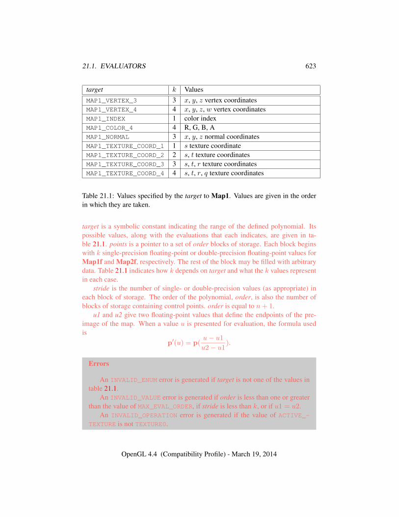
21.1. EVALUATORS 623
target k ValuesMAP1_VERTEX_3 3 x, y, z vertex coordinatesMAP1_VERTEX_4 4 x, y, z, w vertex coordinatesMAP1_INDEX 1 color indexMAP1_COLOR_4 4 R, G, B, AMAP1_NORMAL 3 x, y, z normal coordinatesMAP1_TEXTURE_COORD_1 1 s texture coordinateMAP1_TEXTURE_COORD_2 2 s, t texture coordinatesMAP1_TEXTURE_COORD_3 3 s, t, r texture coordinatesMAP1_TEXTURE_COORD_4 4 s, t, r, q texture coordinates
Table 21.1: Values specified by the target to Map1. Values are given in the orderin which they are taken.
target is a symbolic constant indicating the range of the defined polynomial. Itspossible values, along with the evaluations that each indicates, are given in ta-ble 21.1. points is a pointer to a set of order blocks of storage. Each block beginswith k single-precision floating-point or double-precision floating-point values forMap1f and Map2f, respectively. The rest of the block may be filled with arbitrarydata. Table 21.1 indicates how k depends on target and what the k values representin each case.
stride is the number of single- or double-precision values (as appropriate) ineach block of storage. The order of the polynomial, order, is also the number ofblocks of storage containing control points. order is equal to n+ 1.
u1 and u2 give two floating-point values that define the endpoints of the pre-image of the map. When a value u is presented for evaluation, the formula usedis
p′(u) = p(u− u1
u2− u1).
Errors
An INVALID_ENUM error is generated if target is not one of the values intable 21.1.
An INVALID_VALUE error is generated if order is less than one or greaterthan the value of MAX_EVAL_ORDER, if stride is less than k, or if u1 = u2.
An INVALID_OPERATION error is generated if the value of ACTIVE_-TEXTURE is not TEXTURE0.
OpenGL 4.4 (Compatibility Profile) - March 19, 2014
21.1. EVALUATORS 624
Map2 is analogous to Map1, except that it describes bivariate polynomials ofthe form
p(u, v) =n∑
i=0
m∑j=0
Bni (u)Bm
j (v)Rij .
The form of the Map2 command is
void Map2{fd}( enum target, T u1, T u2, int ustride,int uorder, T v1, T v2, int vstride, int vorder, constT *points );
target is a range type selected from the same group as is used for Map1, exceptthat the string MAP1 is replaced with MAP2. points is a pointer to uorder× vorderblocks of storage. The values comprising Rij are located
ustride× i+ vstride× j
values (either single- or double-precision floating-point, as appropriate) past thefirst value pointed to by points. u1, u2, v1, and v2 define the pre-image rectangleof the map; a domain point (u, v) is evaluated as
p′(u, v) = p(u− u1
u2− u1,v − v1
v2− v1).
The evaluation of a defined map is enabled or disabled with Enable and Dis-able using the constant corresponding to the map as described above. The evaluatormap generates only coordinates for texture unit TEXTURE0.
uorder is equal to n+ 1 and vorder is equal to m+ 1.
Errors
An INVALID_ENUM error is generated if target is not one of the values intable 21.1, with MAP1 replaced by MAP2.
An INVALID_VALUE error is generated if either uorder or vorder is lessthan one or greater than the value of MAX_EVAL_ORDER, if ustride or vstrideis less than k, if u1 = u2, or if v1 = v2.
An INVALID_OPERATION error is generated if the value of ACTIVE_-TEXTURE is not TEXTURE0.
Figure 21.1 describes map evaluation schematically; an evaluation of enabledmaps is effected in one of two ways. The first way is to use
void EvalCoord1{fd}( T u );
OpenGL 4.4 (Compatibility Profile) - March 19, 2014
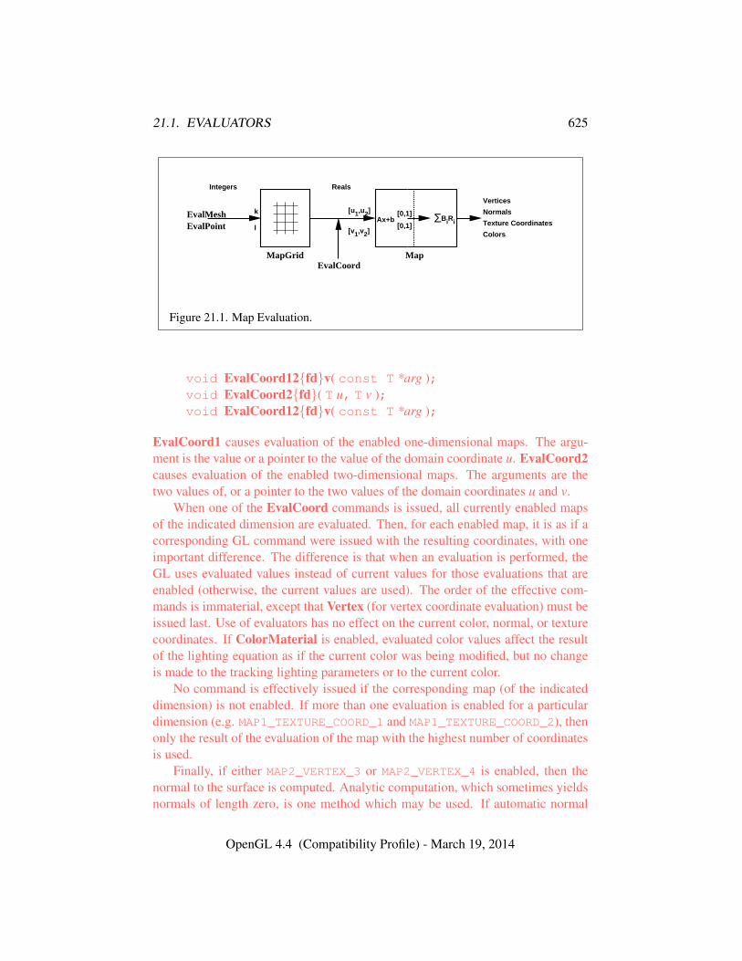
21.1. EVALUATORS 625
EvalMeshEvalPoint
MapGrid MapEvalCoord
k
l
[u1,u2]
[v1,v2]
[0,1]
[0,1]ΣBiRiAx+b
Vertices
Normals
Texture Coordinates
Colors
Integers Reals
Figure 21.1. Map Evaluation.
void EvalCoord12{fd}v( const T *arg );void EvalCoord2{fd}( T u, T v );void EvalCoord12{fd}v( const T *arg );
EvalCoord1 causes evaluation of the enabled one-dimensional maps. The argu-ment is the value or a pointer to the value of the domain coordinate u. EvalCoord2causes evaluation of the enabled two-dimensional maps. The arguments are thetwo values of, or a pointer to the two values of the domain coordinates u and v.
When one of the EvalCoord commands is issued, all currently enabled mapsof the indicated dimension are evaluated. Then, for each enabled map, it is as if acorresponding GL command were issued with the resulting coordinates, with oneimportant difference. The difference is that when an evaluation is performed, theGL uses evaluated values instead of current values for those evaluations that areenabled (otherwise, the current values are used). The order of the effective com-mands is immaterial, except that Vertex (for vertex coordinate evaluation) must beissued last. Use of evaluators has no effect on the current color, normal, or texturecoordinates. If ColorMaterial is enabled, evaluated color values affect the resultof the lighting equation as if the current color was being modified, but no changeis made to the tracking lighting parameters or to the current color.
No command is effectively issued if the corresponding map (of the indicateddimension) is not enabled. If more than one evaluation is enabled for a particulardimension (e.g. MAP1_TEXTURE_COORD_1 and MAP1_TEXTURE_COORD_2), thenonly the result of the evaluation of the map with the highest number of coordinatesis used.
Finally, if either MAP2_VERTEX_3 or MAP2_VERTEX_4 is enabled, then thenormal to the surface is computed. Analytic computation, which sometimes yieldsnormals of length zero, is one method which may be used. If automatic normal
OpenGL 4.4 (Compatibility Profile) - March 19, 2014
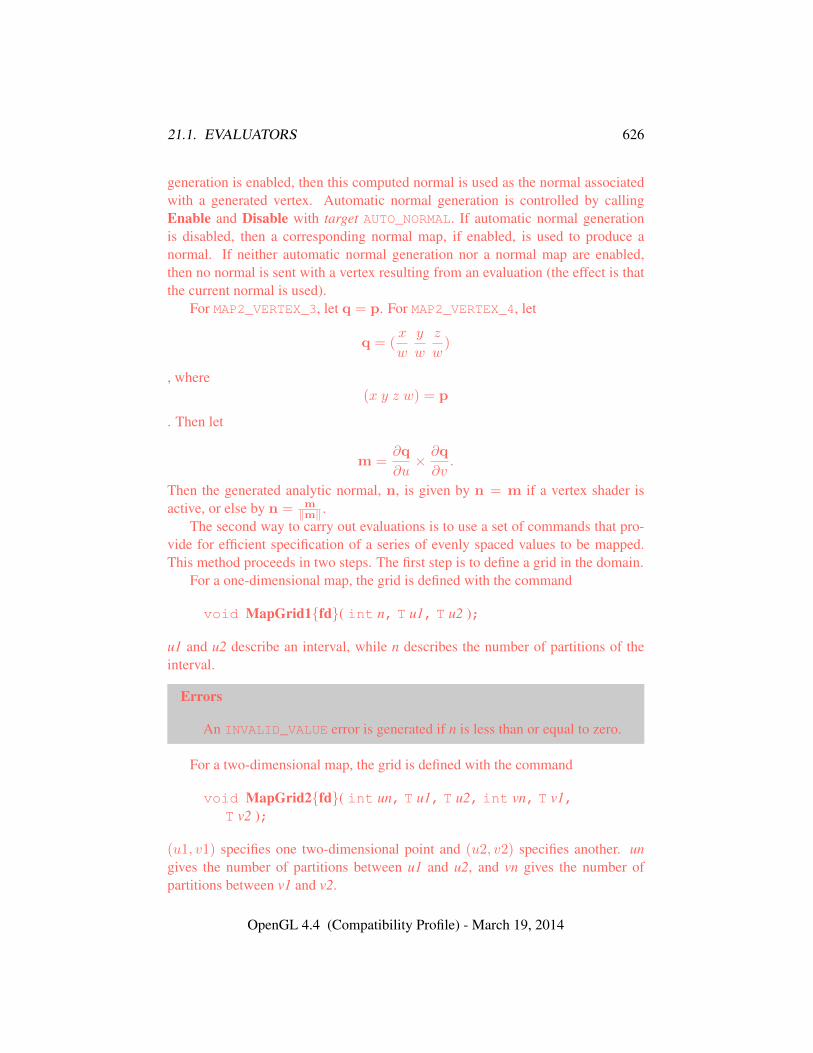
21.1. EVALUATORS 626
generation is enabled, then this computed normal is used as the normal associatedwith a generated vertex. Automatic normal generation is controlled by callingEnable and Disable with target AUTO_NORMAL. If automatic normal generationis disabled, then a corresponding normal map, if enabled, is used to produce anormal. If neither automatic normal generation nor a normal map are enabled,then no normal is sent with a vertex resulting from an evaluation (the effect is thatthe current normal is used).
For MAP2_VERTEX_3, let q = p. For MAP2_VERTEX_4, let
q = (x
w
y
w
z
w)
, where(x y z w) = p
. Then let
m =∂q
∂u× ∂q
∂v.
Then the generated analytic normal, n, is given by n = m if a vertex shader isactive, or else by n = m
‖m‖ .The second way to carry out evaluations is to use a set of commands that pro-
vide for efficient specification of a series of evenly spaced values to be mapped.This method proceeds in two steps. The first step is to define a grid in the domain.
For a one-dimensional map, the grid is defined with the command
void MapGrid1{fd}( int n, T u1, T u2 );
u1 and u2 describe an interval, while n describes the number of partitions of theinterval.
Errors
An INVALID_VALUE error is generated if n is less than or equal to zero.
For a two-dimensional map, the grid is defined with the command
void MapGrid2{fd}( int un, T u1, T u2, int vn, T v1,T v2 );
(u1, v1) specifies one two-dimensional point and (u2, v2) specifies another. ungives the number of partitions between u1 and u2, and vn gives the number ofpartitions between v1 and v2.
OpenGL 4.4 (Compatibility Profile) - March 19, 2014
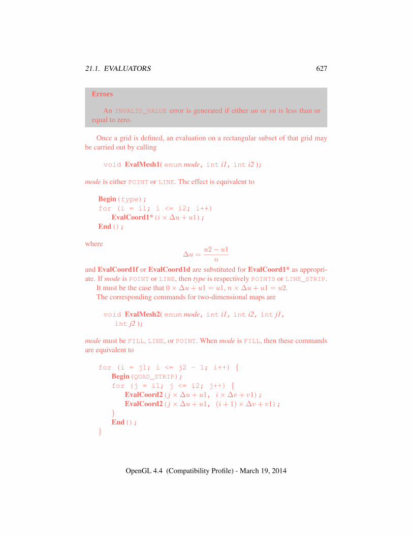
21.1. EVALUATORS 627
Errors
An INVALID_VALUE error is generated if either un or vn is less than orequal to zero.
Once a grid is defined, an evaluation on a rectangular subset of that grid maybe carried out by calling
void EvalMesh1( enum mode, int i1, int i2 );
mode is either POINT or LINE. The effect is equivalent to
Begin(type);for (i = i1; i <= i2; i++)
EvalCoord1*(i×∆u+ u1);End();
where∆u =
u2− u1
n
and EvalCoord1f or EvalCoord1d are substituted for EvalCoord1* as appropri-ate. If mode is POINT or LINE, then type is respectively POINTS or LINE_STRIP.
It must be the case that 0×∆u+ u1 = u1, n×∆u+ u1 = u2.The corresponding commands for two-dimensional maps are
void EvalMesh2( enum mode, int i1, int i2, int j1,int j2 );
mode must be FILL, LINE, or POINT. When mode is FILL, then these commandsare equivalent to
for (i = j1; i <= j2 - 1; i++) {Begin(QUAD_STRIP);for (j = i1; j <= i2; j++) {
EvalCoord2(j ×∆u+ u1, i×∆v + v1);EvalCoord2(j ×∆u+ u1, (i+ 1)×∆v + v1);
}End();
}
OpenGL 4.4 (Compatibility Profile) - March 19, 2014
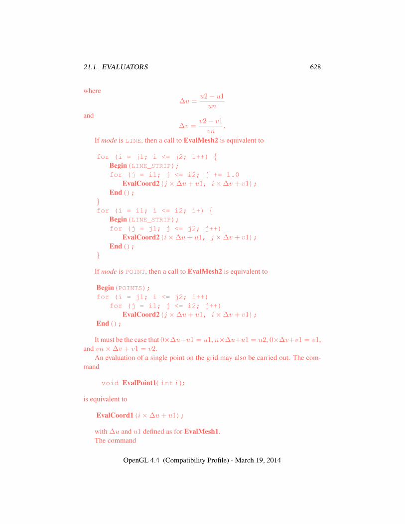
21.1. EVALUATORS 628
where∆u =
u2− u1
un
and∆v =
v2− v1
vn.
If mode is LINE, then a call to EvalMesh2 is equivalent to
for (i = j1; i <= j2; i++) {Begin(LINE_STRIP);for (j = i1; j <= i2; j += 1.0
EvalCoord2(j ×∆u+ u1, i×∆v + v1);End();
}for (i = i1; i <= i2; i+) {
Begin(LINE_STRIP);for (j = j1; j <= j2; j++)
EvalCoord2(i×∆u+ u1, j ×∆v + v1);End();
}
If mode is POINT, then a call to EvalMesh2 is equivalent to
Begin(POINTS);for (i = j1; i <= j2; i++)
for (j = i1; j <= i2; j++)EvalCoord2(j ×∆u+ u1, i×∆v + v1);
End();
It must be the case that 0×∆u+u1 = u1, n×∆u+u1 = u2, 0×∆v+v1 = v1,and vn×∆v + v1 = v2.
An evaluation of a single point on the grid may also be carried out. The com-mand
void EvalPoint1( int i );
is equivalent to
EvalCoord1(i×∆u+ u1);
with ∆u and u1 defined as for EvalMesh1.The command
OpenGL 4.4 (Compatibility Profile) - March 19, 2014
21.1. EVALUATORS 629
void EvalPoint2( int i, int j );
is equivalent to
EvalCoord2(i×∆u+ u1, j ×∆v + v1);
with ∆u, u1, ∆v, and v1 defined as for EvalMesh2.The state required for evaluators potentially consists of 9 one-dimensional map
specifications and 9 two-dimensional map specifications, as well as correspondingflags for each specification indicating which are enabled. Each map specificationconsists of one or two orders, an appropriately sized array of control points, and aset of two values (for a one-dimensional map) or four values (for a two-dimensionalmap) to describe the domain. The maximum possible order, for either u or v, isimplementation-dependent (one maximum applies to both u and v), but must be atleast 8. Each control point consists of between one and four floating-point values(depending on the type of the map). Initially, all maps have order one (making themconstant maps). All vertex coordinate maps produce the coordinates (0, 0, 0, 1)(or the appropriate subset); all normal coordinate maps produce (0, 0, 1); RGBAmaps produce (1, 1, 1, 1); color index maps produce 1.0; and texture coordinatemaps produce (0, 0, 0, 1). In the initial state, all maps are disabled. A flag indi-cates whether or not automatic normal generation is enabled for two-dimensionalmaps. In the initial state, automatic normal generation is disabled. Also requiredare two floating-point values and an integer number of grid divisions for the one-dimensional grid specification and four floating-point values and two integer griddivisions for the two-dimensional grid specification. In the initial state, the boundsof the domain interval for 1-D is 0 and 1.0, respectively; for 2-D, they are (0, 0)and (1.0, 1.0), respectively. The number of grid divisions is one for 1-D and one inboth directions for 2-D. If any evaluation command is issued when no vertex mapis enabled for the map dimension being evaluated, nothing happens.
21.1.1 Evaluator Queries
The command
void GetMap{ifd}v( enum target, enum query, T *data );
returns information about query for evaluator map target in data. target must beone of the map types described in section 21.1, and query must be one of ORDER,COEFF, or DOMAIN.
OpenGL 4.4 (Compatibility Profile) - March 19, 2014
21.2. SELECTION 630
Errors
An INVALID_ENUM error is generated if target is not one of the valid targetparameters to Map1* or Map2*, or if query is not one of ORDER, COEFF, orDOMAIN.
21.2 Selection
Selection is used to determine which primitives are drawn into some region of awindow. The region is defined by the current model-view and perspective matrices.
Selection works by returning an array of integer-valued names. This arrayrepresents the current contents of the name stack. This stack is controlled with thecommands
void InitNames( void );void PopName( void );void PushName( uint name );void LoadName( uint name );
InitNames empties (clears) the name stack. PopName pops one name off the topof the name stack. PushName causes name to be pushed onto the name stack.LoadName replaces the value on the top of the stack with name.
The maximum allowable depth of the name stack is implementation-dependent,but must be at least 64.
Errors
An INVALID_OPERATION error is generated if LoadName is called andthe stack is empty.
A STACK_UNDERFLOW error is generated if PopName is called and thestack is empty.
A STACK_OVERFLOW error is generated if PushName is called and thestack is full.
In selection mode, framebuffer updates as described in chapter 9 are not per-formed. The GL is placed in selection mode with
int RenderMode( enum mode );
OpenGL 4.4 (Compatibility Profile) - March 19, 2014
21.2. SELECTION 631
mode is a symbolic constant: one of RENDER, SELECT, or FEEDBACK. RENDER isthe default, corresponding to rendering as described until now. SELECT specifiesselection mode, and FEEDBACK specifies feedback mode (described below). Useof any of the name stack manipulation commands while the GL is not in selectionmode has no effect.
Errors
An INVALID_ENUM error is generated if mode is not RENDER, SELECT, orFEEDBACK.
An INVALID_OPERATION error is generated if RenderMode is calledwith mode SELECT before SelectBuffer (see below) has been called.
An INVALID_OPERATION error is generated if RenderMode is calledwith mode FEEDBACK before FeedbackBuffer (see section 21.3) has beencalled.
Selection is controlled using
void SelectBuffer( sizei n, uint *buffer );
buffer is a pointer to an array of unsigned integers (called the selection array) to bepotentially filled with names, and n is an integer indicating the maximum numberof values that can be stored in that array.
Errors
An INVALID_VALUE error is generated if n is negative.An INVALID_OPERATION error is generated if the GL is in selection
mode (see RenderMode).
In selection mode, if a point, line, or polygon that would otherwise be sent tothe rasterizer intersects with the clip volume (see section 13.5), then this primi-tive causes a selection hit. Coordinates produced by a RasterPos command thatintersect the clip volume also cause a selection hit, as do the coordinates from aWindowPos command.
In the case of polygons, no hit occurs if the polygon would have been culled,but selection is based on the polygon itself, regardless of the setting of Polygon-Mode. When in selection mode, whenever a name stack manipulation commandis executed or RenderMode is called and there has been a hit since the last timethe stack was manipulated or RenderMode was called, then a hit record is writteninto the selection array.
OpenGL 4.4 (Compatibility Profile) - March 19, 2014
21.3. FEEDBACK 632
A hit record consists of the following items in order: a non-negative integergiving the number of elements on the name stack at the time of the hit, a minimumdepth value, a maximum depth value, and the name stack with the bottommost el-ement first. The minimum and maximum depth values are the minimum and max-imum taken over all the window coordinate z values of each (post-clipping) vertexof each primitive that intersects the clipping volume since the last hit record waswritten. The minimum and maximum (each of which lies in the range [0, 1]) areeach multiplied by 232−1 and rounded to the nearest unsigned integer to obtain thevalues that are placed in the hit record. No depth offset arithmetic (section 14.6.5)is performed on these values.
Hit records are placed in the selection array by maintaining a pointer into thatarray. When selection mode is entered, the pointer is initialized to the beginningof the array. Each time a hit record is copied, the pointer is updated to point atthe array element after the one into which the topmost element of the name stackwas stored. If copying the hit record into the selection array would cause the totalnumber of values to exceed n, then as much of the record as fits in the array iswritten and an overflow flag is set.
Selection mode is exited by calling RenderMode with an argument value otherthan SELECT. When called while in selection mode, RenderMode returns thenumber of hit records copied into the selection array and resets the SelectBufferpointer to its last specified value. Values are not guaranteed to be written into theselection array until RenderMode is called. If the selection array overflow flagwas set, then RenderMode returns −1 and clears the overflow flag. The namestack is cleared and the stack pointer reset whenever RenderMode is called.
The state required for selection consists of the address of the selection arrayand its maximum size, the name stack and its associated pointer, a minimum andmaximum depth value, and several flags. One flag indicates the current Render-Mode value. In the initial state, the GL is in the RENDER mode. Another flag isused to indicate whether or not a hit has occurred since the last name stack ma-nipulation. This flag is reset upon entering selection mode and whenever a namestack manipulation takes place. One final flag is required to indicate whether themaximum number of copied names would have been exceeded. This flag is resetupon entering selection mode. This flag, the address of the selection array, and itsmaximum size are GL client state.
21.3 Feedback
The GL is placed in feedback mode by calling RenderMode with modeFEEDBACK. When in feedback mode, framebuffer updates as described in chap-
OpenGL 4.4 (Compatibility Profile) - March 19, 2014
21.3. FEEDBACK 633
ter 9 are not performed. Instead, information about primitives that would haveotherwise been rasterized is returned to the application via the feedback buffer.
Feedback is controlled using
void FeedbackBuffer( sizei n, enum type, float *buffer );
buffer is a pointer to an array of floating-point values into which feedback informa-tion will be placed, and n is a number indicating the maximum number of valuesthat can be written to that array. type is a symbolic constant describing the infor-mation to be fed back for each vertex (see figure 21.2).
Errors
An INVALID_VALUE error is generated if n is negative.An INVALID_ENUM error is generated if type is not one of the tokens in
table 21.2.An INVALID_OPERATION error is generated if the GL is in feedback
mode (see RenderMode).
While in feedback mode, each primitive that would be rasterized (or bitmapor call to DrawPixels or CopyPixels, if the raster position is valid) generates ablock of values that get copied into the feedback array. If doing so would causethe number of entries to exceed the maximum, the block is partially written so asto fill the array (if there is any room left at all). The first block of values generatedafter the GL enters feedback mode is placed at the beginning of the feedback array,with subsequent blocks following. Each block begins with a code indicating theprimitive type, followed by values that describe the primitive’s vertices and asso-ciated data. Entries are also written for bitmaps and pixel rectangles. Feedbackoccurs after polygon culling (section 14.6.1) and PolygonMode interpretation ofpolygons (section 14.6.4) has taken place. It may also occur after polygons withmore than three edges are broken up into triangles (if the GL implementation ren-ders polygons by performing this decomposition). x, y, and z coordinates returnedby feedback are window coordinates; if w is returned, it is in clip coordinates. Nodepth offset arithmetic (section 14.6.5) is performed on the z values. In the caseof bitmaps and pixel rectangles, the coordinates returned are those of the currentraster position.
The texture coordinates and colors returned are those resulting from the clip-ping operations described in section 13.5.1. Only coordinates for texture unitTEXTURE0 are returned even for implementations which support multiple textureunits. The colors returned are the primary colors.
OpenGL 4.4 (Compatibility Profile) - March 19, 2014
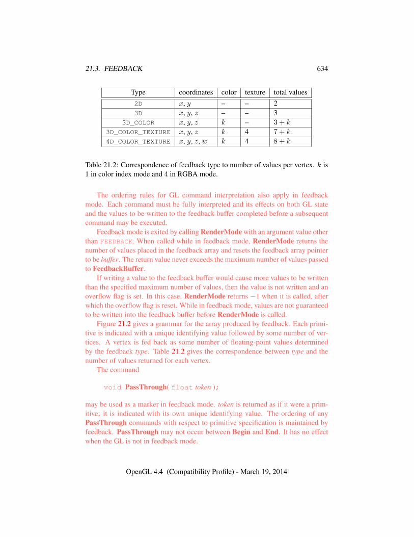
21.3. FEEDBACK 634
Type coordinates color texture total values2D x, y – – 23D x, y, z – – 3
3D_COLOR x, y, z k – 3 + k
3D_COLOR_TEXTURE x, y, z k 4 7 + k
4D_COLOR_TEXTURE x, y, z, w k 4 8 + k
Table 21.2: Correspondence of feedback type to number of values per vertex. k is1 in color index mode and 4 in RGBA mode.
The ordering rules for GL command interpretation also apply in feedbackmode. Each command must be fully interpreted and its effects on both GL stateand the values to be written to the feedback buffer completed before a subsequentcommand may be executed.
Feedback mode is exited by calling RenderMode with an argument value otherthan FEEDBACK. When called while in feedback mode, RenderMode returns thenumber of values placed in the feedback array and resets the feedback array pointerto be buffer. The return value never exceeds the maximum number of values passedto FeedbackBuffer.
If writing a value to the feedback buffer would cause more values to be writtenthan the specified maximum number of values, then the value is not written and anoverflow flag is set. In this case, RenderMode returns −1 when it is called, afterwhich the overflow flag is reset. While in feedback mode, values are not guaranteedto be written into the feedback buffer before RenderMode is called.
Figure 21.2 gives a grammar for the array produced by feedback. Each primi-tive is indicated with a unique identifying value followed by some number of ver-tices. A vertex is fed back as some number of floating-point values determinedby the feedback type. Table 21.2 gives the correspondence between type and thenumber of values returned for each vertex.
The command
void PassThrough( float token );
may be used as a marker in feedback mode. token is returned as if it were a prim-itive; it is indicated with its own unique identifying value. The ordering of anyPassThrough commands with respect to primitive specification is maintained byfeedback. PassThrough may not occur between Begin and End. It has no effectwhen the GL is not in feedback mode.
OpenGL 4.4 (Compatibility Profile) - March 19, 2014
21.4. DISPLAY LISTS 635
The state required for feedback is the pointer to the feedback array, the maxi-mum number of values that may be placed there, and the feedback type. An over-flow flag is required to indicate whether the maximum allowable number of feed-back values has been written; initially this flag is cleared. These state variables areGL client state. Feedback also relies on the same mode flag as selection to indicatewhether the GL is in feedback, selection, or normal rendering mode.
21.4 Display Lists
A display list is a group of GL commands and arguments that has been stored forsubsequent execution. The GL may be instructed to process a particular displaylist (possibly repeatedly) by providing a number that uniquely specifies it. Doingso causes the commands within the list to be executed just as if they were givennormally. The only exception pertains to commands that rely upon client state.When such a command is accumulated into the display list (that is, when issued,not when executed), the client state in effect at that time applies to the command.Only server state is affected when the command is executed. As always, pointerswhich are passed as arguments to commands are dereferenced when the commandis issued. (Vertex array pointers are dereferenced when the commands ArrayEle-ment, DrawArrays, DrawElements, or DrawRangeElements are accumulatedinto a display list.)
A display list is begun by calling
void NewList( uint n, enum mode );
n is a positive integer to which the display list that follows is assigned, and mode is asymbolic constant that controls the behavior of the GL during display list creation.If mode is COMPILE, then commands are not executed as they are placed in thedisplay list. If mode is COMPILE_AND_EXECUTE then commands are executed asthey are encountered, then placed in the display list.
Errors
An INVALID_ENUM error is generated if mode is not COMPILE orCOMPILE_AND_EXECUTE.
An INVALID_VALUE error is generated if n is zero.An INVALID_OPERATION error is generated if NewList is called a second
time before calling EndList.
After calling NewList, all subsequent GL commands are placed in the displaylist (in the order the commands are issued) until a call to
OpenGL 4.4 (Compatibility Profile) - March 19, 2014
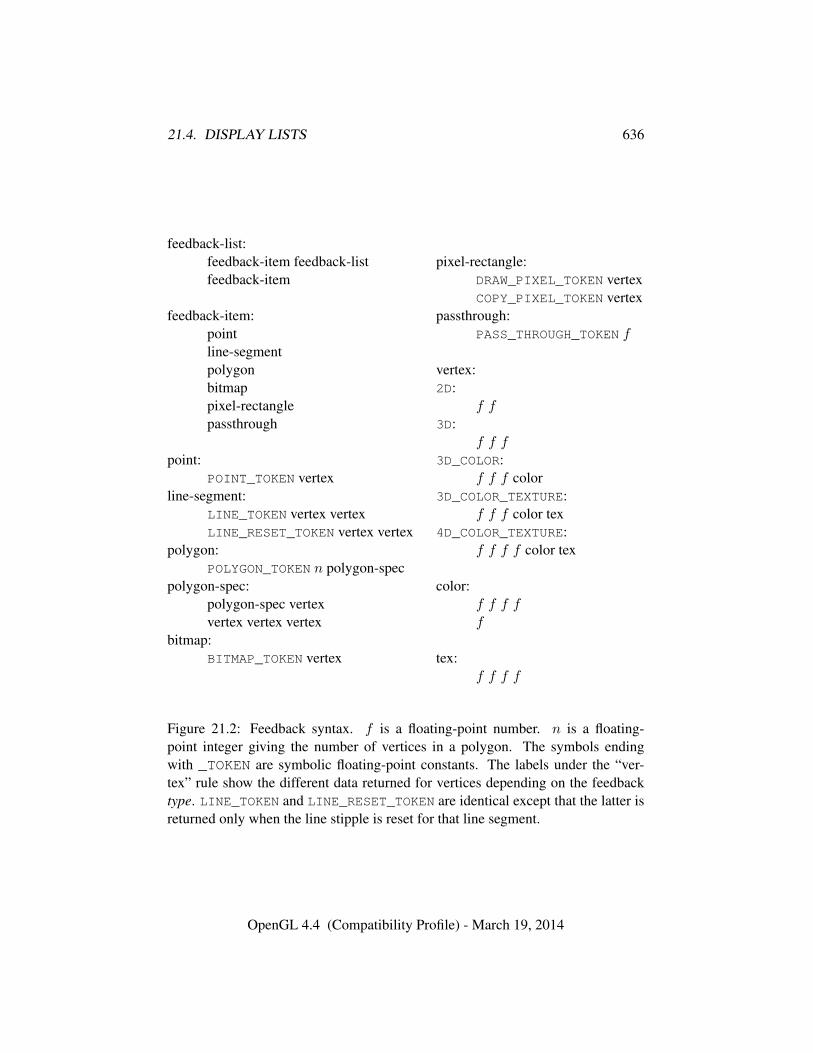
21.4. DISPLAY LISTS 636
feedback-list:feedback-item feedback-listfeedback-item
feedback-item:pointline-segmentpolygonbitmappixel-rectanglepassthrough
point:POINT_TOKEN vertex
line-segment:LINE_TOKEN vertex vertexLINE_RESET_TOKEN vertex vertex
polygon:POLYGON_TOKEN n polygon-spec
polygon-spec:polygon-spec vertexvertex vertex vertex
bitmap:BITMAP_TOKEN vertex
pixel-rectangle:DRAW_PIXEL_TOKEN vertexCOPY_PIXEL_TOKEN vertex
passthrough:PASS_THROUGH_TOKEN f
vertex:2D:
f f3D:
f f f3D_COLOR:
f f f color3D_COLOR_TEXTURE:
f f f color tex4D_COLOR_TEXTURE:
f f f f color tex
color:f f f ff
tex:f f f f
Figure 21.2: Feedback syntax. f is a floating-point number. n is a floating-point integer giving the number of vertices in a polygon. The symbols endingwith _TOKEN are symbolic floating-point constants. The labels under the “ver-tex” rule show the different data returned for vertices depending on the feedbacktype. LINE_TOKEN and LINE_RESET_TOKEN are identical except that the latter isreturned only when the line stipple is reset for that line segment.
OpenGL 4.4 (Compatibility Profile) - March 19, 2014
21.4. DISPLAY LISTS 637
void EndList( void );
occurs, after which the GL returns to its normal command execution state. It isonly when EndList occurs that the specified display list is actually associated withthe index indicated with NewList.
Errors
An INVALID_OPERATION error is generated if EndList is called withouta previous matching NewList.
An OUT_OF_MEMORY error is generated if EndList is called and the spec-ified display list cannot be stored because insufficient memory is available. Inthis case no change is made to the previous contents of the display list, if any,and no other change is made to the GL state, except for the state changed byexecution of GL commands when the display list mode is COMPILE_AND_-EXECUTE.
Once defined, a display list is executed by calling
void CallList( uint n );
n gives the index of the display list to be called. This causes the commands savedin the display list to be executed, in order, just as if they were issued without usinga display list.
Errors
An INVALID_VALUE error is generated if n is zero.
The command
void CallLists( sizei n, enum type, const void *lists );
provides an efficient means for executing a number of display lists. n is an in-teger indicating the number of display lists to be called, and lists is a pointerthat points to an array of offsets. Each offset is constructed as determined bylists as follows. First, type may be one of the constants BYTE, UNSIGNED_BYTE,SHORT, UNSIGNED_SHORT, INT, UNSIGNED_INT, or FLOAT indicating that the ar-ray pointed to by lists is an array of bytes, unsigned bytes, shorts, unsigned shorts,integers, unsigned integers, or floats, respectively. In this case each offset is foundby simply converting each array element to an integer (floating-point values aretruncated to negative infinity). Further, type may be one of 2_BYTES, 3_BYTES,
OpenGL 4.4 (Compatibility Profile) - March 19, 2014
21.4. DISPLAY LISTS 638
or 4_BYTES, indicating that the array contains sequences of 2, 3, or 4 unsignedbytes, in which case each integer offset is constructed according to the followingalgorithm:
offset← 0for i = 1 to b
offset← offset shifted left 8 bitsoffset← offset+ byteadvance to next byte in the array
b is 2, 3, or 4, as indicated by type. If n = 0, CallLists does nothing.Each of the n constructed offsets is taken in order and added to a display list
base to obtain a display list number. For each number, the indicated display list isexecuted.
Errors
An INVALID_VALUE error is generated if n is negative.
The display list base is set by calling
void ListBase( uint base );
to specify the offset.Indicating a display list index that does not correspond to any display list has
no effect. CallList or CallLists may appear inside a display list. (If the mode sup-plied to NewList is COMPILE_AND_EXECUTE, then the appropriate lists are exe-cuted, but the CallList or CallLists, rather than those lists’ constituent commands,is placed in the list under construction.) To avoid the possibility of infinite recur-sion resulting from display lists calling one another, an implementation-dependentlimit is placed on the nesting level of display lists during display list execution.This limit may be determined by calling GetIntegerv with pname MAX_LIST_-
NESTING, and must be at least 64.Two commands are provided to manage display list indices.
uint GenLists( sizei s );
returns an integer n such that the indices n, . . . , n+s−1 are previously unused (i.e.there are s previously unused display list indices starting at n). GenLists also hasthe effect of creating an empty display list for each of the indices n, . . . , n+ s− 1,so that these indices all become used. GenLists returns zero if there is no group ofs contiguous previously unused display list indices, or if s = 0.
OpenGL 4.4 (Compatibility Profile) - March 19, 2014
21.4. DISPLAY LISTS 639
Errors
An INVALID_VALUE error is generated if s is negative.
boolean IsList( uint list );
returns TRUE if list is the index of some display list.A contiguous group of display lists may be deleted by calling
void DeleteLists( uint list, sizei range );
where list is the index of the first display list to be deleted and range is the numberof display lists to be deleted. All information about the display lists is lost, and theindices become unused. Indices to which no display list corresponds are ignored.If range is zero, nothing happens.
Errors
An INVALID_VALUE error is generated if range is negative.
21.4.1 Commands Not Usable In Display Lists
Certain commands, when called while compiling a display list, are not compiledinto the display list but are executed immediately. These commands fall in severalcategories including
Display lists: GenLists and DeleteLists.Render modes: FeedbackBuffer, SelectBuffer, and RenderMode.Vertex arrays: ClientActiveTexture, ColorPointer, EdgeFlagPointer, Fog-
CoordPointer, IndexPointer, InterleavedArrays, NormalPointer, Secondary-ColorPointer, TexCoordPointer, VertexAttribPointer, VertexAttribIPointer,VertexAttribLPointer, VertexPointer, PrimitiveRestartIndex, GenVertexAr-rays, DeleteVertexArrays, and BindVertexArray.
Client state: EnableClientState, DisableClientState, EnableVertexAttrib-Array, DisableVertexAttribArray, PushClientAttrib, and PopClientAttrib.
Pixels and textures: PixelStore, ReadPixels, GenTextures, DeleteTex-tures, AreTexturesResident, TexBuffer, TexStorage1D, TexStorage2D, TexS-torage3D, and GenerateMipmap.
Occlusion queries: GenQueries and DeleteQueries.Buffer objects: GenBuffers, DeleteBuffers, BindBuffer, BindBufferRange,
BindBufferBase, TransformFeedbackVaryings, MemoryBarrier, BufferData,
OpenGL 4.4 (Compatibility Profile) - March 19, 2014
21.4. DISPLAY LISTS 640
BufferSubData, MapBuffer, MapBufferRange, FlushMappedBufferRange,and UnmapBuffer.
Sampler objects: GenSamplers and DeleteSamplers.Transform feedback objects: GenTransformFeedbacks and DeleteTrans-
formFeedbacks.Framebuffer and renderbuffer objects: GenFramebuffers, BindFrame-
buffer, DeleteFramebuffers, CheckFramebufferStatus, GenRenderbuffers,BindRenderbuffer, DeleteRenderbuffers, RenderbufferStorage, Render-bufferStorageMultisample, FramebufferTexture, FramebufferTexture1D,FramebufferTexture2D, FramebufferTexture3D, FramebufferTextureLayer,FramebufferRenderbuffer, and BlitFramebuffer.
Program and shader objects: CreateProgram, CreateShader, Create-ShaderProgram, GenProgramPipelines, BindProgramPipelines DeletePro-gramPipelines, DeleteProgram, DeleteShader, AttachShader, DetachShader,BindAttribLocation, BindFragDataLocation, CompileShader, ShaderSource,LinkProgram, and ValidateProgram.
GL command stream management: ClientWaitSync, FenceSync, Finish, andFlush.
Debug output: DebugMessageControl, DebugMessageInsert, DebugMes-sageCallback, and GetDebugMessageLog.
Multi-object binds: BindBuffersBase, BindBuffersRange, BindTextures,BindSamplers, BindImageTextures, and BindVertexBuffers.
Other queries: All query commands whose names begin with Get and Is.An INVALID_OPERATION error is generated if the commands DrawAr-
raysInstanced or DrawElementsInstanced (see section 10.5) are called duringdisplay list compilation.
Commands that source data from buffer objects dereference the buffer objectdata in question at display list compile time, rather than encoding the buffer ID andbuffer offset into the display list. Only GL commands that are executed immedi-ately, rather than being compiled into a display list, are permitted to use a bufferobject as a data sink.
TexImage3D, TexImage2D, TexImage1D, Histogram, and ColorTableare executed immediately when called with the corresponding proxy argumentsPROXY_TEXTURE_3D, PROXY_TEXTURE_2D_ARRAY, or PROXY_TEXTURE_-
CUBE_MAP_ARRAY; PROXY_TEXTURE_2D, PROXY_TEXTURE_1D_ARRAY, orPROXY_TEXTURE_CUBE_MAP; PROXY_TEXTURE_1D; PROXY_HISTOGRAM;and PROXY_COLOR_TABLE, PROXY_POST_CONVOLUTION_COLOR_TABLE, orPROXY_POST_COLOR_MATRIX_COLOR_TABLE.
When a program object is in use, a display list may be executed whose vertexattribute calls do not match up exactly with what is expected by the vertex shader
OpenGL 4.4 (Compatibility Profile) - March 19, 2014
21.5. HINTS 641
contained in that program object. Handling of this mismatch is described in sec-tion 11.1.1.
Display lists require one bit of state to indicate whether a GL command shouldbe executed immediately or placed in a display list. In the initial state, commandsare executed immediately. If the bit indicates display list creation, an index isrequired to indicate the current display list being defined. Another bit indicates,during display list creation, whether or not commands should be executed as theyare compiled into the display list. One integer is required for the current ListBasesetting; its initial value is zero. Finally, state must be maintained to indicate whichintegers are currently in use as display list indices. In the initial state, no indicesare in use.
21.5 Hints
Certain aspects of GL behavior, when there is room for variation, may be controlledwith hints. A hint is specified using
void Hint( enum target, enum hint );
target is a symbolic constant indicating the behavior to be controlled, and hint is asymbolic constant indicating what type of behavior is desired. The possible targetsare described in table 21.3. For each target, hint must be one of FASTEST, indi-cating that the most efficient option should be chosen; NICEST, indicating that thehighest quality option should be chosen; and DONT_CARE, indicating no preferencein the matter.
For the texture compression hint, a hint of FASTEST indicates that texture im-ages should be compressed as quickly as possible, while NICEST indicates thatthe texture images be compressed with as little image degradation as possible.FASTEST should be used for one-time texture compression, and NICEST shouldbe used if the compression results are to be retrieved by GetCompressedTexIm-age (section 8.11) for reuse.
The interpretation of hints is implementation-dependent. An implementationmay ignore them entirely.
The initial value of all hints is DONT_CARE.
Errors
An INVALID_ENUM error is generated if target is not one of the values intable 21.3.
An INVALID_ENUM error is generated if hint is not FASTEST, NICEST, or
OpenGL 4.4 (Compatibility Profile) - March 19, 2014
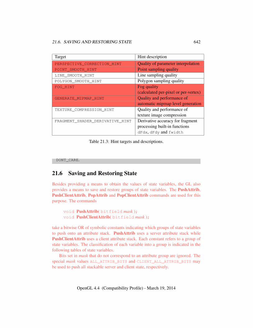
21.6. SAVING AND RESTORING STATE 642
Target Hint descriptionPERSPECTIVE_CORRECTION_HINT Quality of parameter interpolationPOINT_SMOOTH_HINT Point sampling qualityLINE_SMOOTH_HINT Line sampling qualityPOLYGON_SMOOTH_HINT Polygon sampling qualityFOG_HINT Fog quality
(calculated per-pixel or per-vertex)GENERATE_MIPMAP_HINT Quality and performance of
automatic mipmap level generationTEXTURE_COMPRESSION_HINT Quality and performance of
texture image compressionFRAGMENT_SHADER_DERIVATIVE_HINT Derivative accuracy for fragment
processing built-in functionsdFdx, dFdy and fwidth
Table 21.3: Hint targets and descriptions.
DONT_CARE.
21.6 Saving and Restoring State
Besides providing a means to obtain the values of state variables, the GL alsoprovides a means to save and restore groups of state variables. The PushAttrib,PushClientAttrib, PopAttrib and PopClientAttrib commands are used for thispurpose. The commands
void PushAttrib( bitfield mask );void PushClientAttrib( bitfield mask );
take a bitwise OR of symbolic constants indicating which groups of state variablesto push onto an attribute stack. PushAttrib uses a server attribute stack whilePushClientAttrib uses a client attribute stack. Each constant refers to a group ofstate variables. The classification of each variable into a group is indicated in thefollowing tables of state variables.
Bits set in mask that do not correspond to an attribute group are ignored. Thespecial mask values ALL_ATTRIB_BITS and CLIENT_ALL_ATTRIB_BITS maybe used to push all stackable server and client state, respectively.
OpenGL 4.4 (Compatibility Profile) - March 19, 2014
21.6. SAVING AND RESTORING STATE 643
Errors
A STACK_OVERFLOW error is generated if PushAttrib is called and theattribute stack depth is equal to the value of MAX_ATTRIB_STACK_DEPTH.
A STACK_OVERFLOW error is generated if PushClientAttrib is calledand the client attribute stack depth is equal to the value of MAX_CLIENT_-ATTRIB_STACK_DEPTH.
The commands
void PopAttrib( void );void PopClientAttrib( void );
reset the values of those state variables that were saved with the last correspondingPushAttrib or PopClientAttrib. Those not saved remain unchanged.
Errors
A STACK_UNDERFLOW error is generated if PopAttrib is called and theattribute stack depth is zero.
A STACK_UNDERFLOW error is generated if PopClientAttrib is called andthe client attribute stack depth is zero.
Table 21.4 shows the attribute groups with their corresponding symbolic con-stant names and stacks.
When PushAttrib is called with TEXTURE_BIT set, the priorities, border col-ors, filter modes, wrap modes, and other state of the currently bound texture ob-jects (see tables 23.19- 23.20), as well as the current texture bindings and enables,are pushed onto the attribute stack. (Unbound texture objects are not pushed orrestored.) When an attribute set that includes texture information is popped, thebindings and enables are first restored to their pushed values, then the bound tex-ture object’s parameters are restored to their pushed values. The bindings and statefor sampler objects are not pushed or popped.
Operations on attribute groups push or pop texture state within that group forall texture units. When state for a group is pushed, all state corresponding toTEXTURE0 is pushed first, followed by state corresponding to TEXTURE1, and soon up to and including the state corresponding to TEXTUREk where k + 1 is thevalue of MAX_TEXTURE_UNITS. When state for a group is popped, texture state isrestored in the opposite order that it was pushed, starting with state correspondingto TEXTUREk and ending with TEXTURE0. Identical rules are observed for client
OpenGL 4.4 (Compatibility Profile) - March 19, 2014
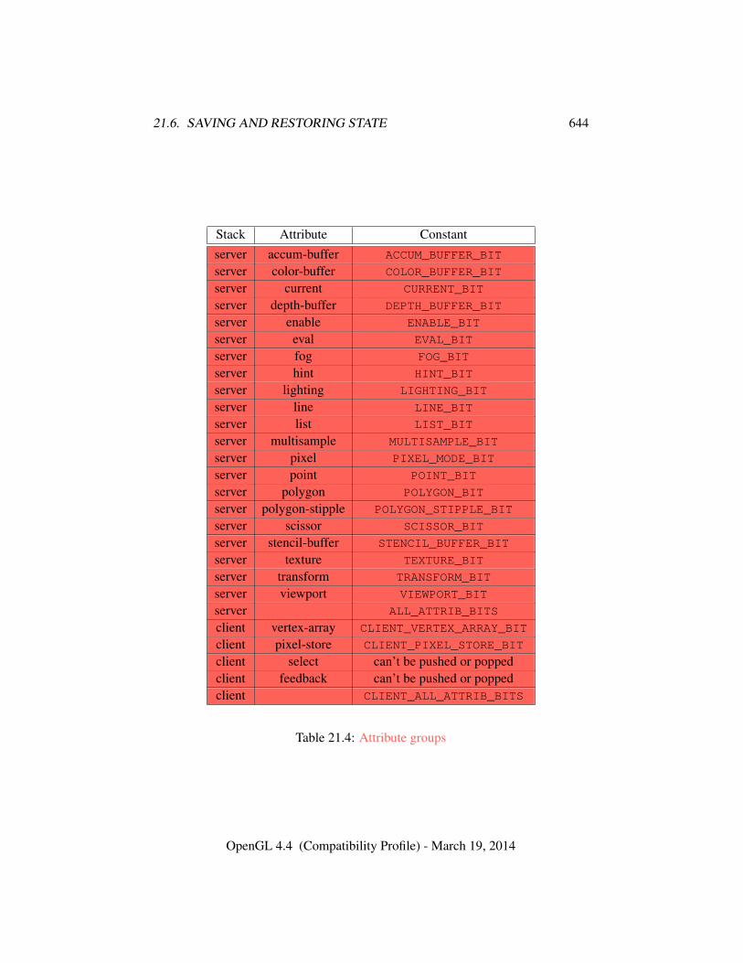
21.6. SAVING AND RESTORING STATE 644
Stack Attribute Constantserver accum-buffer ACCUM_BUFFER_BIT
server color-buffer COLOR_BUFFER_BIT
server current CURRENT_BIT
server depth-buffer DEPTH_BUFFER_BIT
server enable ENABLE_BIT
server eval EVAL_BIT
server fog FOG_BIT
server hint HINT_BIT
server lighting LIGHTING_BIT
server line LINE_BIT
server list LIST_BIT
server multisample MULTISAMPLE_BIT
server pixel PIXEL_MODE_BIT
server point POINT_BIT
server polygon POLYGON_BIT
server polygon-stipple POLYGON_STIPPLE_BIT
server scissor SCISSOR_BIT
server stencil-buffer STENCIL_BUFFER_BIT
server texture TEXTURE_BIT
server transform TRANSFORM_BIT
server viewport VIEWPORT_BIT
server ALL_ATTRIB_BITS
client vertex-array CLIENT_VERTEX_ARRAY_BIT
client pixel-store CLIENT_PIXEL_STORE_BIT
client select can’t be pushed or poppedclient feedback can’t be pushed or poppedclient CLIENT_ALL_ATTRIB_BITS
Table 21.4: Attribute groups
OpenGL 4.4 (Compatibility Profile) - March 19, 2014

21.6. SAVING AND RESTORING STATE 645
texture state push and pop operations. Matrix stacks are never pushed or poppedwith PushAttrib, PushClientAttrib, PopAttrib, or PopClientAttrib.
The depth of each attribute stack is implementation-dependent but must be atleast 16. The state required for each attribute stack is potentially 16 copies of eachstate variable, 16 masks indicating which groups of variables are stored in eachstack entry, and an attribute stack pointer. In the initial state, both attribute stacksare empty.
OpenGL 4.4 (Compatibility Profile) - March 19, 2014
Chapter 22
Context State Queries
The state required to describe the GL machine is enumerated in chapter 23, and isset using commands described in previous chapters.
State that is part of GL objects can usually be queried using commands de-scribed together with the commands to set that state. Such commands operateeither directly on a named object, or indirectly through a binding in the GL context(such as a currently bound framebuffer object).
The commands in this chapter describe queries for state directly associatedwith the context, rather than with an object. Data conversions may be done whenquerying context state, as described in section 2.2.2.
22.1 Simple Queries
Much of the GL state is completely identified by symbolic constants. The valuesof these state variables can be obtained using a set of Get commands.
Valid values of the symbolic constants allowed as parameter names to the var-ious queries in this section are not summarized here, because there are many al-lowed parameters. Instead they are described elsewhere in the Specification to-gether with the commands such state is relevant to, as well as in the state tables inchapter 23.
There are five commands for obtaining simple state variables:
void GetBooleanv( enum pname, boolean *data );void GetIntegerv( enum pname, int *data );void GetInteger64v( enum pname, int64 *data );void GetFloatv( enum pname, float *data );void GetDoublev( enum pname, double *data );
646
22.1. SIMPLE QUERIES 647
The commands obtain boolean, integer, 64-bit integer, floating-point, or double-precision state variables. pname is a symbolic constant indicating the state variableto return. data is a pointer to a scalar or array of the indicated type in which toplace the returned data.
Errors
An INVALID_ENUM error is generated if pname is not state queriable withthese commands.
Indexed simple state variables are queried with the commands
void GetBooleani v( enum target, uint index,boolean *data );
void GetIntegeri v( enum target, uint index, int *data );void GetFloati v( enum target, uint index, float *data );void GetDoublei v( enum target, uint index, double *data );void GetInteger64i v( enum target, uint index,
int64 *data );
target is the name of the indexed state and index is the index of the particularelement being queried. data is a pointer to a scalar or array of the indicated type inwhich to place the returned data.
Errors
An INVALID_ENUM error is generated if target is not indexed state queri-able with these commands.
An INVALID_VALUE error is generated if index is outside the valid rangefor the indexed state target.
Finally,
boolean IsEnabled( enum cap );
can be used to determine if cap is currently enabled (as with Enable) or disabled.
Errors
An INVALID_ENUM error is generated if cap is not enable state queriablewith IsEnabled.
OpenGL 4.4 (Compatibility Profile) - March 19, 2014
22.2. POINTER ANDSTRING QUERIES 648
boolean IsEnabledi( enum target, uint index );
can be used to determine if the indexed state corresponding to target and index isenabled or disabled.
Errors
An INVALID_ENUM error is generated if target is not indexed enable statequeriable with IsEnabled.
An INVALID_VALUE error is generated if index is outside the valid rangefor the indexed state target.
22.2 Pointer andString Queries
Pointers in the current GL context are queried with the command
void GetPointerv( enum pname, void **params );
pname is a symbolic constant indicating the pointer to return. params is a pointerto a variable in which to place the single returned pointer value.
pnames of DEBUG_CALLBACK_FUNCTION
and DEBUG_CALLBACK_USER_PARAM, return debug output state as described insection 20.9. pnames SELECTION_BUFFER_POINTER and FEEDBACK_BUFFER_-POINTER, return the pointers set with SelectBuffer and FeedbackBuffer, respec-tively. pnames VERTEX_ARRAY_POINTER, NORMAL_ARRAY_POINTER, COLOR_-ARRAY_POINTER, SECONDARY_COLOR_ARRAY_POINTER, INDEX_ARRAY_-
POINTER, TEXTURE_COORD_ARRAY_POINTER, FOG_COORD_ARRAY_POINTER,are EDGE_FLAG_ARRAY_POINTER, respectively return the corresponding valuestored in the currently bound vertex array object.
String queries return pointers to UTF-8 encoded, null-terminated static stringsdescribing properties of the current GL context 1. The command
ubyte *GetString( enum name );
accepts name values of RENDERER, VENDOR, EXTENSIONS, VERSION, andSHADING_LANGUAGE_VERSION. The format of the RENDERER and VENDOR
1Applications making copies of these static strings should never use a fixed-length buffer, becausethe strings may grow unpredictably between releases, resulting in buffer overflow when copying.This is particularly true of the EXTENSIONS string, which has become extremely long in someGL implementations.
OpenGL 4.4 (Compatibility Profile) - March 19, 2014
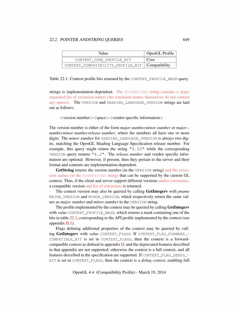
22.2. POINTER ANDSTRING QUERIES 649
Value OpenGL ProfileCONTEXT_CORE_PROFILE_BIT Core
CONTEXT_COMPATIBILITY_PROFILE_BIT Compatibility
Table 22.1: Context profile bits returned by the CONTEXT_PROFILE_MASK query.
strings is implementation-dependent. The EXTENSIONS string contains a spaceseparated list of extension names (the extension names themselves do not containany spaces). The VERSION and SHADING_LANGUAGE_VERSION strings are laidout as follows:
<version number><space><vendor-specific information>
The version number is either of the form major number.minor number or major -number.minor number.release number, where the numbers all have one or moredigits. The minor number for SHADING_LANGUAGE_VERSION is always two dig-its, matching the OpenGL Shading Language Specification release number. Forexample, this query might return the string "4.20" while the correspondingVERSION query returns "4.2". The release number and vendor specific infor-mation are optional. However, if present, then they pertain to the server and theirformat and contents are implementation-dependent.
GetString returns the version number (in the VERSION string) and the exten-sion names (in the EXTENSIONS string) that can be supported by the current GLcontext. Thus, if the client and server support different versions and/or extensions,a compatible version and list of extensions is returned.
The context version may also be queried by calling GetIntegerv with pnameMAJOR_VERSION and MINOR_VERSION, which respectively return the same val-ues as major number and minor number in the VERSION string.
The profile implemented by the context may be queried by calling GetIntegervwith value CONTEXT_PROFILE_MASK, which returns a mask containing one of thebits in table 22.1, corresponding to the API profile implemented by the context (seeappendix D.1).
Flags defining additional properties of the context may be queried by call-ing GetIntegerv with value CONTEXT_FLAGS. If CONTEXT_FLAG_FORWARD_-COMPATIBLE_BIT is set in CONTEXT_FLAGS, then the context is a forward-compatible context as defined in appendix D, and the deprecated features describedin that appendix are not supported; otherwise the context is a full context, and allfeatures described in the specification are supported. If CONTEXT_FLAG_DEBUG_-BIT is set in CONTEXT_FLAGS, then the context is a debug context, enabling full
OpenGL 4.4 (Compatibility Profile) - March 19, 2014
22.2. POINTER ANDSTRING QUERIES 650
support for debug output as described in chapter 20.Indexed strings are queried with the command
ubyte *GetStringi( enum name, uint index );
name is the name of the indexed state and index is the index of the particular ele-ment being queried.
If name is EXTENSIONS, the extension name corresponding to the indexthsupported extension will be returned. index may range from zero to the valueof NUM_EXTENSIONS minus one. All extension names, and only the extensionnames returned in GetString(EXTENSIONS) will be returned as individual names,but there is no defined relationship between the order in which names appear inthe non-indexed string and the order in which they appear in the indexed query.
There is no defined relationship between any particular extension name and theindex values; an extension name may correspond to a different index in differentGL contexts and/or implementations.
If name is SHADING_LANGUAGE_VERSION, a version string for one of the sup-ported versions of the OpenGL Shading Language and OpenGL ES Shading Lan-guage is returned. index may range from zero to the value of NUM_SHADING_-LANGUAGE_VERSIONS minus one. The format of the returned string is identical tothe text that may follow #version in shader program source and is formatted asthe version number followed, for versions in which language profiles are defined,by a space and a profile name. For example, a returned string containing "420core" indicates support for OpenGL Shading Language 4.20, core profile. Anempty string indicates support for OpenGL Shading Language 1.10, which did notinclude the #version compiler directive. The profile string will always be presentin the returned string when it is accepted by that version of the Shading Language,even though there is a default profile string in versions 1.50 and greater. Versionstrings 100 and 300 es correspond to OpenGL ES Shading Language versions100 and 300.
An index of zero will always return the string for the version of the most recentshading language supported by the GL and the profile of the shading languagecorresponding to the profile of the API (e.g. the first entry returned in an OpenGL4.30 core profile context will be "430 core" and the first entry returned in anOpenGL 4.30 compatibility profile context will be "430 compatibility").There is no defined ordering of the returned strings for other values of index.
Errors
An INVALID_ENUM error is generated if name is not SHADING_-
LANGUAGE_VERSION or EXTENSIONS.
OpenGL 4.4 (Compatibility Profile) - March 19, 2014
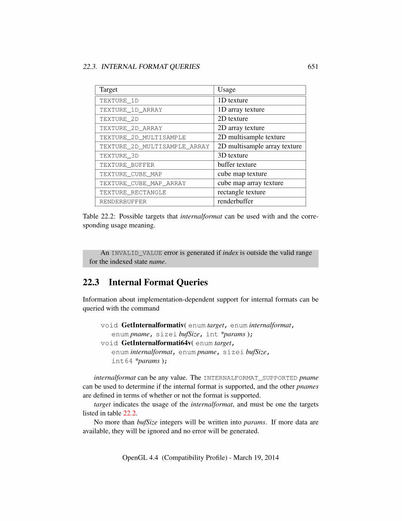
22.3. INTERNAL FORMAT QUERIES 651
Target UsageTEXTURE_1D 1D textureTEXTURE_1D_ARRAY 1D array textureTEXTURE_2D 2D textureTEXTURE_2D_ARRAY 2D array textureTEXTURE_2D_MULTISAMPLE 2D multisample textureTEXTURE_2D_MULTISAMPLE_ARRAY 2D multisample array textureTEXTURE_3D 3D textureTEXTURE_BUFFER buffer textureTEXTURE_CUBE_MAP cube map textureTEXTURE_CUBE_MAP_ARRAY cube map array textureTEXTURE_RECTANGLE rectangle textureRENDERBUFFER renderbuffer
Table 22.2: Possible targets that internalformat can be used with and the corre-sponding usage meaning.
An INVALID_VALUE error is generated if index is outside the valid rangefor the indexed state name.
22.3 Internal Format Queries
Information about implementation-dependent support for internal formats can bequeried with the command
void GetInternalformativ( enum target, enum internalformat,enum pname, sizei bufSize, int *params );
void GetInternalformati64v( enum target,enum internalformat, enum pname, sizei bufSize,int64 *params );
internalformat can be any value. The INTERNALFORMAT_SUPPORTED pnamecan be used to determine if the internal format is supported, and the other pnamesare defined in terms of whether or not the format is supported.
target indicates the usage of the internalformat, and must be one the targetslisted in table 22.2.
No more than bufSize integers will be written into params. If more data areavailable, they will be ignored and no error will be generated.
OpenGL 4.4 (Compatibility Profile) - March 19, 2014
22.3. INTERNAL FORMAT QUERIES 652
pname indicates the information to query. The following subsections list thevalid values for pname and defines their meaning and the values that may be re-turned. In the following descriptions, the term resource is used to generically referto an object of the appropriate type that has been created with internalformat andtarget. If the particular target and internalformat combination do not make sense,or if a particular type of target is not supported by the implementation the unsup-ported answer should be given. This is not an error.
All properties can be queried via either GetInternalformat* command. Dataconversions are done as defined in section 2.2.2.
22.3.1 Supported Operation Queries
Queries that return information about supported types of operations will return oneof the following values in params:
• NONE: the requested resource or operation is not supported at all by the im-plementation.
• CAVEAT_SUPPORT: the requested operation is supported by the implemen-tation, but there may be some implementation-specific caveats that makesupport less than optimal. For example using the feature may result in re-duced performance (relative to other formats or features), such as softwarerendering or other mechanisms of emulating the desired feature.
If a query reports that there is a caveat and the debug output functionalityis enabled (see section 20), the GL will generate a debug output messagedescribing the caveat. The message has the source DEBUG_SOURCE_API, thetype DEBUG_TYPE_PERFORMANCE, and an implementation-dependent ID.
• FULL_SUPPORT: the requested operation is fully supported by the imple-mentation.
Possible pnames for supported types of operations, and their meanings, in-clude:
• AUTO_GENERATE_MIPMAP: Support for automatic generation of mipmapsfor the resource is returned in params.
• CLEAR_BUFFER: Support for using the resource with ClearBuffer*Datacommands is returned in params.
• CLEAR_TEXTURE: Support for using the resource with ClearTex*Imagecommands is returned in params.
OpenGL 4.4 (Compatibility Profile) - March 19, 2014
22.3. INTERNAL FORMAT QUERIES 653
• COMPUTE_TEXTURE: Support for using the resource as a source for texturesampling in a compute shader is written to params.
• FILTER: Support for filter types other than NEAREST or NEAREST_-
MIPMAP_NEAREST for the resource is written to params. This indicatesif sampling from such resources supports setting the MIN/MAG filters toLINEAR values.
• FRAGMENT_TEXTURE: Support for using the resource as a source for texturesampling in a fragment shader is written to params.
• FRAMEBUFFER_BLEND: Support for rendering to the resource via frame-buffer attachment when blending is enabled is returned in params.
• FRAMEBUFFER_RENDERABLE: Support for rendering to the resource viaframebuffer attachment is returned in params.
• FRAMEBUFFER_RENDERABLE_LAYERED: Support for layered rendering tothe resource via framebuffer attachment is returned in params.
• GEOMETRY_TEXTURE: Support for using the resource as a source for texturesampling in a geometry shader is written to params.
• MANUAL_GENERATE_MIPMAP: Support for manually generating mipmapsfor the resource is returned in params.
• READ_PIXELS: Support for reading pixels from the resource when it is at-tached to a framebuffer is returned in params.
• SHADER_IMAGE_ATOMIC: Support for using the resource with atomic mem-ory operations from shaders is written to params.
• SHADER_IMAGE_LOAD: Support for using the resource with image load op-erations in shaders is written to params. In this case the internalformat is thevalue of the format parameter that would be passed to BindImageTexture.
• SHADER_IMAGE_STORE: Support for using the resource with image storeoperations in shaders is written to params. In this case the internalformat isthe value of the format parameter that is passed to BindImageTexture.
• SIMULTANEOUS_TEXTURE_AND_DEPTH_TEST: Support for using the re-source both as a source for texture sampling while it is bound as a bufferfor depth test is written to params. For example, a depth (or stencil) texturecould be bound simultaneously for texturing while it is bound as a depth
OpenGL 4.4 (Compatibility Profile) - March 19, 2014
22.3. INTERNAL FORMAT QUERIES 654
(and/or stencil) buffer without causing a feedback loop, provided that depthwrites are disabled.
• SIMULTANEOUS_TEXTURE_AND_DEPTH_WRITE: Support for using the re-source both as a source for texture sampling while performing depth writesto the resources is written to params. For example, a depth-stencil texturecould be bound simultaneously for stencil texturing while it is bound as adepth buffer. Feedback loops cannot occur because sampling a stencil tex-ture only returns the stencil portion, and thus writes to the depth buffer donot modify the stencil portions.
• SIMULTANEOUS_TEXTURE_AND_STENCIL_TEST: Support for using the re-source both as a source for texture sampling while it is bound as a buffer forstencil test is written to params. For example, a depth (or stencil) texturecould be bound simultaneously for texturing while it is bound as a depth(and/or stencil) buffer without causing a feedback loop, provided that stencilwrites are disabled.
• SIMULTANEOUS_TEXTURE_AND_STENCIL_WRITE: Support for using theresource both as a source for texture sampling while performing stencilwrites to the resources is written to params. For example, a depth-stenciltexture could be bound simultaneously for depth-texturing while it is boundas a stencil buffer. Feedback loops cannot occur because sampling a depthtexture only returns the depth portion, and thus writes to the stencil buffercould not modify the depth portions.
• SRGB_READ: Support for converting from sRGB colorspace on read opera-tions (see section 8.24) from the resource is returned in params.
• SRGB_WRITE: Support for converting to sRGB colorspace on write opera-tions to the resource is returned in params. This indicates that writing toframebuffers with this internal format will encode to sRGB color spaceswhen FRAMEBUFFER_SRGB is enabled (see section 17.3.9).
• TESS_CONTROL_TEXTURE: Support for using the resource as a source fortexture sampling in a tessellation control shader is written to params.
• TESS_EVALUATION_TEXTURE: Support for using the resource as a sourcefor texture sampling in a tessellation evaluation shader is written to params.
• TEXTURE_GATHER: Support for using the resource with texture gather oper-ations is written to params.
OpenGL 4.4 (Compatibility Profile) - March 19, 2014
22.3. INTERNAL FORMAT QUERIES 655
• TEXTURE_GATHER_SHADOW: Support for using resource with texture gatheroperations with shadow samplers is written to params.
• TEXTURE_SHADOW: Support for using the resource with shadow samplers iswritten to params.
• TEXTURE_VIEW: Support for using the resource with the TextureView com-mand is returned in params.
• VERTEX_TEXTURE: Support for using the resource as a source for texturesampling in a vertex shader is written to params.
22.3.2 Other Internal Format Queries
Other supported values for pname, their meanings, and their possible return valuesinclude:
• COLOR_COMPONENTS: If the internal format contains any color components(R, G, B, or A), TRUE is returned in params. If the internal format is unsup-ported or contains no color components, FALSE is returned.
• COLOR_ENCODING: The color encoding for the resource is returned inparams. Possible values for color buffers are LINEAR or SRGB, for linearor sRGB-encoded color components, respectively. For non-color formats(such as depth or stencil), or for unsupported resources, the value NONE isreturned.
• COLOR_RENDERABLE: If internalformat is color-renderable (as defined insection 9.4), TRUE is returned in params. If the internal format is unsup-ported, or the internal format is not color-renderable, FALSE is returned.
• DEPTH_COMPONENTS: If the internal format contains a depth component(D), TRUE is returned in params. If the internal format is unsupported orcontains no depth component, FALSE is returned.
• DEPTH_RENDERABLE: If internalformat is depth-renderable (as defined insection 9.4), TRUE is returned in params. If the internal format is unsup-ported, or if the internal format is not depth-renderable, FALSE is returned.
• GET_TEXTURE_IMAGE_FORMAT: The implementation-preferred format topass to GetTexImage when querying texture image data from this resource.Possible values include any value that is legal to pass for the format parame-ter to GetTexImage, or NONE if the resource does not support this operation,or if GetTexImage is not supported.
OpenGL 4.4 (Compatibility Profile) - March 19, 2014
22.3. INTERNAL FORMAT QUERIES 656
• GET_TEXTURE_IMAGE_TYPE: The implementation-preferred type to pass toGetTexImage when querying texture image data from this resource. Possi-ble values include any value that is legal to pass for the type parameter toGetTexImage, or NONE if the resource does not support this operation, or ifGetTexImage is not supported.
• IMAGE_COMPATIBILITY_CLASS: The compatibility class of the resourcewhen used as an image texture is returned in params. This corre-sponds to the value from the Class column in table 8.34. The possi-ble values returned are IMAGE_CLASS_4_X_32, IMAGE_CLASS_2_X_32,IMAGE_CLASS_1_X_32, IMAGE_CLASS_4_X_16, IMAGE_CLASS_2_X_-16, IMAGE_CLASS_1_X_16, IMAGE_CLASS_4_X_8, IMAGE_CLASS_2_-X_8, IMAGE_CLASS_1_X_8, IMAGE_CLASS_11_11_10, and IMAGE_-
CLASS_10_10_10_2, which correspond to the 4x32, 2x32, 1x32, 4x16,2x16, 1x16, 4x8, 2x8, 1x8, the class (a) 11/11/10 packed floating-point for-mat, and the class (b) 10/10/10/2 packed formats, respectively. If the re-source is not supported for image textures, or if image textures are not sup-ported, NONE is returned.
• IMAGE_FORMAT_COMPATIBILITY_TYPE: The matching criteria use for theresource when used as an image textures is returned in params. Thisis equivalent to calling GetTexParameter with pname set to IMAGE_-
FORMAT_COMPATIBILITY_TYPE. Possible values are IMAGE_FORMAT_-
COMPATIBILITY_BY_SIZE or IMAGE_FORMAT_COMPATIBILITY_BY_-
CLASS. If the resource is not supported for image textures, or if image tex-tures are not supported, NONE is returned.
• IMAGE_PIXEL_FORMAT: The pixel format of the resource when used as animage texture is returned in params. This is the value from the Pixel formatcolumn in table 8.34. If the resource is not supported for image textures, orif image textures are not supported, NONE is returned.
• IMAGE_PIXEL_TYPE: The pixel type of the resource when used as an imagetexture is returned in params. This is the value from the Pixel type columnin table 8.34. If the resource is not supported for image textures, or if imagetextures are not supported, NONE is returned.
• IMAGE_TEXEL_SIZE: The size of a texel when the resource when used as animage texture is returned in params. This is the value from the Size columnin table 8.34. If the resource is not supported for image textures, or if imagetextures are not supported, zero is returned.
OpenGL 4.4 (Compatibility Profile) - March 19, 2014
22.3. INTERNAL FORMAT QUERIES 657
• INTERNALFORMAT_PREFERRED: The implementation-preferred internalformat for representing resources of the specified internalformat is returnedin params. The preferred internal format should have no less precision thanthe requested one. If the specified internalformat is already a preferred for-mat, or is there is no better format that is compatible, the queried internalfor-mat value is written to params. If the internalformat is not supported, NONEis returned.
• INTERNALFORMAT_RED_SIZE, INTERNALFORMAT_GREEN_-
SIZE, INTERNALFORMAT_BLUE_SIZE, INTERNALFORMAT_ALPHA_SIZE,INTERNALFORMAT_DEPTH_SIZE, INTERNALFORMAT_STENCIL_SIZE, orINTERNALFORMAT_SHARED_SIZE
For uncompressed internal formats, queries of these values return the actualresolutions that would be used for storing image array components for theresource. For compressed internal formats, the resolutions returned specifythe component resolution of an uncompressed internal format that producesan image of roughly the same quality as the compressed algorithm. For tex-tures this query will return the same information as querying GetTexLevel-Parameter* for TEXTURE_*_SIZE would return. If the internal format isunsupported, or if a particular component is not present in the format, 0 iswritten to params.
• INTERNALFORMAT_RED_TYPE, INTERNALFORMAT_GREEN_-
TYPE, INTERNALFORMAT_BLUE_TYPE, INTERNALFORMAT_ALPHA_TYPE,INTERNALFORMAT_DEPTH_TYPE, or INTERNALFORMAT_STENCIL_TYPE
For uncompressed internal formats, queries for these values return the datatype used to store the component. For compressed internal formats the typesreturned specify how components are interpreted after decompression. Fortextures this query returns the same information as querying GetTexLevel-Parameter* for TEXTURE_*TYPE would return. Possible values returnedinclude NONE, SIGNED_NORMALIZED, UNSIGNED_NORMALIZED, FLOAT,INT, and UNSIGNED_INT, representing missing, signed normalized fixedpoint, unsigned normalized fixed point, floating-point, signed unnormalizedinteger, and unsigned unnormalized integer components respectively. NONEis returned for all component types if the format is unsupported.
• INTERNALFORMAT_SUPPORTED: If internalformat is an internal format thatis supported by the implementation in at least some subset of possible oper-ations, TRUE is written to params. If internalformat if not a valid token forany internal format usage, FALSE is returned.
OpenGL 4.4 (Compatibility Profile) - March 19, 2014
22.3. INTERNAL FORMAT QUERIES 658
internalformats that must be supported include:
– sized internal formats from tables 8.19- 8.21 and 8.23,
– any specific compressed internal format from table 8.22,
– any image unit format from table 8.33,
– any generic compressed internal format from table 8.22, if the imple-mentation accepts it for any texture specification commands, and
– any unsized or base internal format, if the implementation accepts it fortexture or image specification.
In other words, any internalformat accepted by any of the com-mands: ClearBufferData, ClearBufferSubData, CompressedTexIm-age1D, CompressedTexImage2D, CompressedTexImage3D, CopyTex-Image1D, CopyTexImage2D, RenderbufferStorage, Renderbuffer-StorageMultisample, TexBuffer, TexImage1D, TexImage2D, TexIm-age3D, TexImage2DMultisample, TexImage3DMultisample, TexStor-age1D, TexStorage2D, TexStorage3D, TexStorage2DMultisample, TexS-torage3DMultisample, and TextureView, and any valid format accepted byBindImageTexture, must be supported.
• MAX_COMBINED_DIMENSIONS: The maximum combined dimensions forthe resource is returned in params. The combined dimensions is the prod-uct of the individual dimensions of the resource. For multisampled surfacesthe number of samples is considered an additional dimension. Note that thevalue returned can be ≥ 232 and should be queried with GetInternalfor-mati64v.
This value should be considered a recommendations for applications. Theremay be system-dependant reasons why allocations larger than this size mayfail, even if there might appear to be sufficient memory available whenqueried via some other means. This also does not provide a guarantee thatallocations smaller than this will succeed because this value is not affectedby existing resource allocations.
For one-dimensional targets this is the maximum single dimension. Forone-dimensional array targets this is the maximum combined width andlayers. For two-dimensional targets this is the maximum combined widthand height. For two-dimensional multisample targets this is the combinedwidth, height and samples. For two-dimensional array targets this is the maxcombined width, height and layers. For two-dimensional multisample arraytargets, this is the max combined width, height, layers and samples. For
OpenGL 4.4 (Compatibility Profile) - March 19, 2014
22.3. INTERNAL FORMAT QUERIES 659
three-dimensional targets this is the maximum combined width, height anddepth. For cube map targets this is the maximum combined width, heightand faces. For cube map array targets this is the maximum width, height andlayer-faces. If the resource is unsupported, zero is returned.
• MAX_DEPTH: The maximum supported depth for the resource is returned inparams. For resources with three or more dimensions, the third dimension isconsidered the depth. If the resource does not have at least three dimensions,or if the resource is unsupported, zero is returned.
• MAX_HEIGHT: The maximum supported height for the resource is returned inparams. For resources with two or more dimensions, the second dimensionis considered the height. If the resource does not have at least two dimen-sions, or if the resource is unsupported, zero is returned.
• MAX_LAYERS: The maximum supported number of layers for the resource isreturned in params. For 1D array targets, the value returned is the same asthe MAX_HEIGHT. For 2D and cube array targets, the value returned is thesame as the MAX_DEPTH. If the resource does not support layers, or if theresource is unsupported, zero is returned.
• MAX_WIDTH: The maximum supported width for the resource is returnedin params. For resources with only one-dimension, this one dimension isconsidered the width. If the resource is unsupported, zero is returned.
• MIPMAP: If the resource supports mipmaps, TRUE is returned in params. Ifthe resource is not supported, or if mipmaps are not supported for this typeof resource, FALSE is returned.
• NUM_SAMPLE_COUNTS: The number of sample counts that would be re-turned by querying SAMPLES is returned in params.
– If internalformat is not color-renderable, depth-renderable, or stencil-renderable (as defined in section 9.4), or if target does not support mul-tiple samples (is not TEXTURE_2D_MULTISAMPLE, TEXTURE_2D_-MULTISAMPLE_ARRAY, or RENDERBUFFER), zero is returned.
• READ_PIXELS_FORMAT: The format to pass to ReadPixels to obtain thebest performance and image quality when reading from framebuffers withinternalformat is returned in params. Possible values include any value thatis legal to pass for the format parameter to ReadPixels, or NONE if internal-format is not supported or can never be a valid source for ReadPixels.
OpenGL 4.4 (Compatibility Profile) - March 19, 2014
22.3. INTERNAL FORMAT QUERIES 660
• READ_PIXELS_TYPE: The type to pass to ReadPixels to obtain the bestperformance and image quality when reading from framebuffers with inter-nalformat is returned in params. Possible values include any value that islegal to pass for the type parameter to ReadPixels, or NONE if the internalformat is not supported or can never be a source for ReadPixels.
• SAMPLES: The sample counts supported for internalformat and target arewritten into params, in descending numeric order. Only positive values arereturned.
– Note that querying SAMPLES with a bufSize of one will return just themaximum supported number of samples for this format.
– The maximum value in SAMPLES is guaranteed to be at least the lowestof the following:∗ The value of MAX_INTEGER_SAMPLES, if internalformat is a
signed or unsigned integer format.∗ The value of MAX_DEPTH_TEXTURE_SAMPLES, if internalformat
is a depth/stencil-renderable format and target is TEXTURE_2D_-MULTISAMPLE or TEXTURE_2D_MULTISAMPLE_ARRAY.∗ The value of MAX_COLOR_TEXTURE_SAMPLES, if internalfor-
mat is a color-renderable format and target is TEXTURE_2D_-
MULTISAMPLE or TEXTURE_2D_MULTISAMPLE_ARRAY.∗ The value of MAX_SAMPLES.
– If internalformat is not color-renderable, depth-renderable, or stencil-renderable (as defined in section 9.4), or if target does not sup-port multiple samples (ie other than TEXTURE_2D_MULTISAMPLE,TEXTURE_2D_MULTISAMPLE_ARRAY, or RENDERBUFFER), params isnot modified.
• STENCIL_COMPONENTS: If the internal format contains a stencil component(S), TRUE is returned in params. If the internal format is unsupported orcontains no stencil component, FALSE is returned.
• STENCIL_RENDERABLE: If internalformat is stencil-renderable (as definedin section 9.4), TRUE is returned in params. If the internal format is unsup-ported, or if the internal format is not stencil-renderable, FALSE is returned.
• TEXTURE_COMPRESSED: If internalformat is a compressed format that issupported for this type of resource, TRUE is returned in params. If the inter-nal format is not compressed, or the type of resource is not supported, FALSEis returned.
OpenGL 4.4 (Compatibility Profile) - March 19, 2014
22.3. INTERNAL FORMAT QUERIES 661
• TEXTURE_COMPRESSED_BLOCK_HEIGHT: If the resource contains a com-pressed format, the height of a compressed block (in bytes) is returned inparams. If the internal format is not compressed, or the resource is not sup-ported, 0 is returned.
• TEXTURE_COMPRESSED_BLOCK_SIZE: If the resource contains a com-pressed format the number of bytes per block is returned in params. If theinternal format is not compressed, or the resource is not supported, 0 is re-turned. (combined with the above, allows the bitrate to be computed, andmay be useful in conjunction with ARB compressed texture pixel storage).
• TEXTURE_COMPRESSED_BLOCK_WIDTH: If the resource contains a com-pressed format, the width of a compressed block (in bytes) is returned inparams. If the internal format is not compressed, or the resource is not sup-ported, 0 is returned.
• TEXTURE_IMAGE_FORMAT: The implementation-preferred format to pass toTexImage*D or TexSubImage*D when specifying texture image data forthis resource is returned in params. Possible values include any value thatis legal to pass for the format parameter to the Tex*Image*D commands, orNONE if the resource is not supported for this operation.
• TEXTURE_IMAGE_TYPE: The implementation-preferred type to pass to Tex-Image*D or TexSubImage*D when specifying texture image data for thisresource is returned in params. Possible values include any value that is le-gal to pass for the type parameter to the Tex*Image*D commands, or NONEif the resource is not supported for this operation.
• VIEW_COMPATIBILITY_CLASS: The compatibility class of the resourcewhen used as a texture view is returned in params. The compatibility classis one of the values from the Class column of table 8.29. If the resource hasno other formats that are compatible, the resource does not support views, orif texture views are not supported, NONE is returned.
Errors
An INVALID_ENUM error is generated if target is not one of the targets intable 22.2, or if pname is not one of the parameters described above.
An INVALID_VALUE error is generated if bufSize is negative.
OpenGL 4.4 (Compatibility Profile) - March 19, 2014
Chapter 23
State Tables
The tables on the following pages indicate which state variables are obtained withwhat commands. State variables that can be obtained using any of GetBooleanv,GetIntegerv, GetInteger64v, GetFloatv, or GetDoublev are listed with just oneof these commands – the one that is most appropriate given the type of the datato be returned. These state variables cannot be obtained using IsEnabled. How-ever, state variables for which IsEnabled is listed as the query command can alsobe obtained using GetBooleanv, GetIntegerv, GetInteger64v, GetFloatv, andGetDoublev. State variables for which any other command is listed as the querycommand can be obtained by using that command or any of its typed variants,although information may be lost when not using the listed command. Unless oth-erwise specified, when floating-point state is returned as integer values or integerstate is returned as floating-point values it is converted in the fashion described insection 2.2.2.
State table entries which are required only by the imaging subset (see sec-tion 8.4.2) are typeset against a gray background .
State table entries indicate a type for each variable. Table 23.1 explains thesetypes. The type actually identifies all state associated with the indicated descrip-tion; in certain cases only a portion of this state is returned. This is the case withall matrices, where only the top entry on the stack is returned; with clip planes,where only the selected clip plane is returned; with parameters describing lights,where only the value pertaining to the selected light is returned; with evaluatormaps, where only the selected map is returned; and with textures, where only theselected texture or texture parameter is returned. Finally, a “–” in the attribute col-umn indicates that the indicated value is not included in any attribute group (andthus can not be pushed or popped with PushAttrib, PushClientAttrib, PopAttrib,or PopClientAttrib).
662

663
The M and m entries for initial minmax table values represent the maximumand minimum possible representable values, respectively.
The abbreviations max, min, and no. are used interchangeably with maximum,minimum, and number, respectively, to help fit tables without overflowing pages.
OpenGL 4.4 (Compatibility Profile) - March 19, 2014
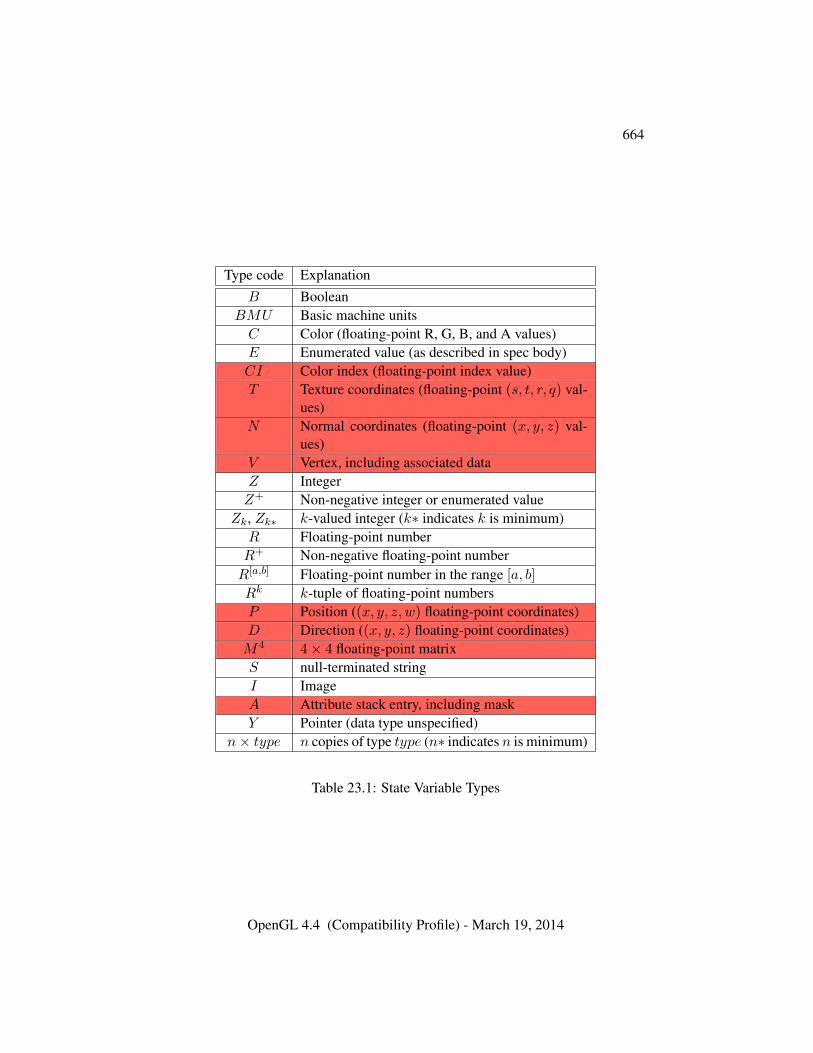
664
Type code ExplanationB Boolean
BMU Basic machine unitsC Color (floating-point R, G, B, and A values)E Enumerated value (as described in spec body)CI Color index (floating-point index value)T Texture coordinates (floating-point (s, t, r, q) val-
ues)N Normal coordinates (floating-point (x, y, z) val-
ues)V Vertex, including associated dataZ IntegerZ+ Non-negative integer or enumerated value
Zk, Zk∗ k-valued integer (k∗ indicates k is minimum)R Floating-point numberR+ Non-negative floating-point numberR[a,b] Floating-point number in the range [a, b]
Rk k-tuple of floating-point numbersP Position ((x, y, z, w) floating-point coordinates)D Direction ((x, y, z) floating-point coordinates)M4 4× 4 floating-point matrixS null-terminated stringI ImageA Attribute stack entry, including maskY Pointer (data type unspecified)
n× type n copies of type type (n∗ indicates n is minimum)
Table 23.1: State Variable Types
OpenGL 4.4 (Compatibility Profile) - March 19, 2014
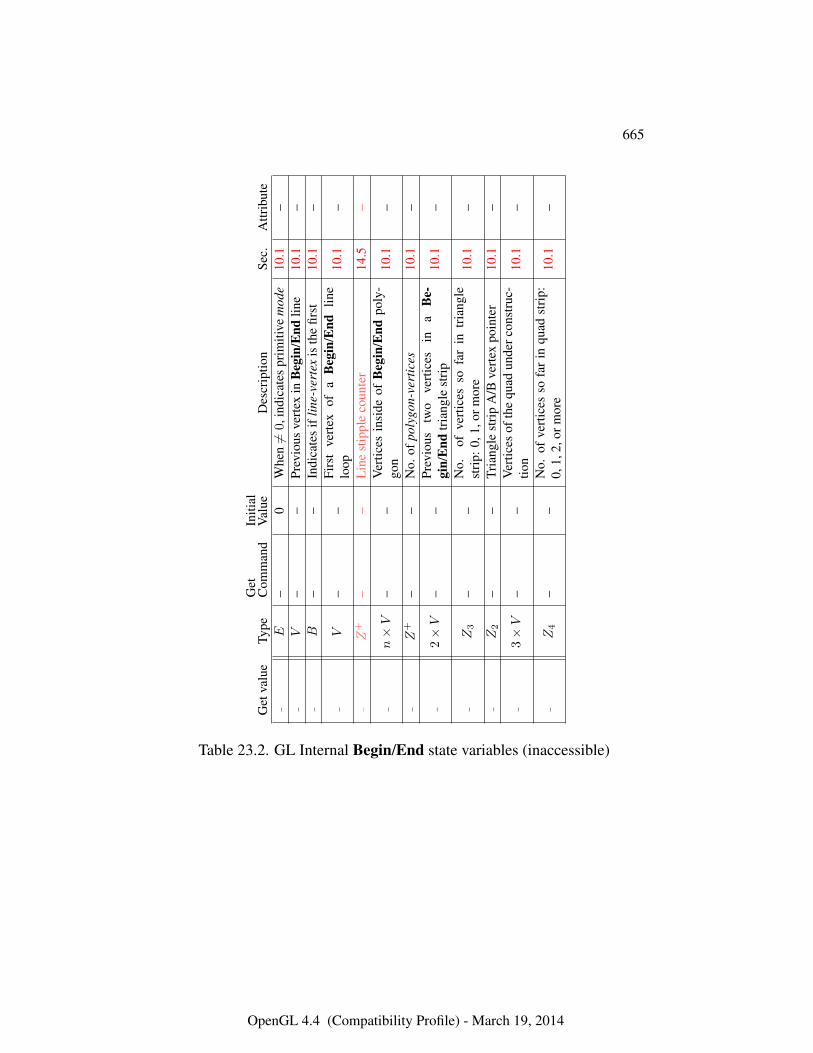
665
Get
valu
eTy
peG
etC
omm
and
Initi
alV
alue
Des
crip
tion
Sec.
Attr
ibut
e–
E–
0W
hen6=
0,in
dica
tes
prim
itive
mod
e10
.1–
–V
––
Prev
ious
vert
exin
Beg
in/E
ndlin
e10
.1–
–B
––
Indi
cate
sif
line-
vert
exis
the
first
10.1
–
–V
––
Firs
tve
rtex
ofa
Beg
in/E
ndlin
elo
op10
.1–
–Z
+–
–L
ine
stip
ple
coun
ter
14.5
–
–n×V
––
Ver
tices
insi
deof
Beg
in/E
ndpo
ly-
gon
10.1
–
–Z
+–
–N
o.of
poly
gon-
vert
ices
10.1
–
–2×V
––
Prev
ious
two
vert
ices
ina
Be-
gin/
End
tria
ngle
stri
p10
.1–
–Z3
––
No.
ofve
rtic
esso
far
intr
iang
lest
rip:
0,1,
orm
ore
10.1
–
–Z2
––
Tria
ngle
stri
pA
/Bve
rtex
poin
ter
10.1
–
–3×V
––
Ver
tices
ofth
equ
adun
derc
onst
ruc-
tion
10.1
–
–Z4
––
No.
ofve
rtic
esso
far
inqu
adst
rip:
0,1,
2,or
mor
e10
.1–
Table 23.2. GL Internal Begin/End state variables (inaccessible)
OpenGL 4.4 (Compatibility Profile) - March 19, 2014
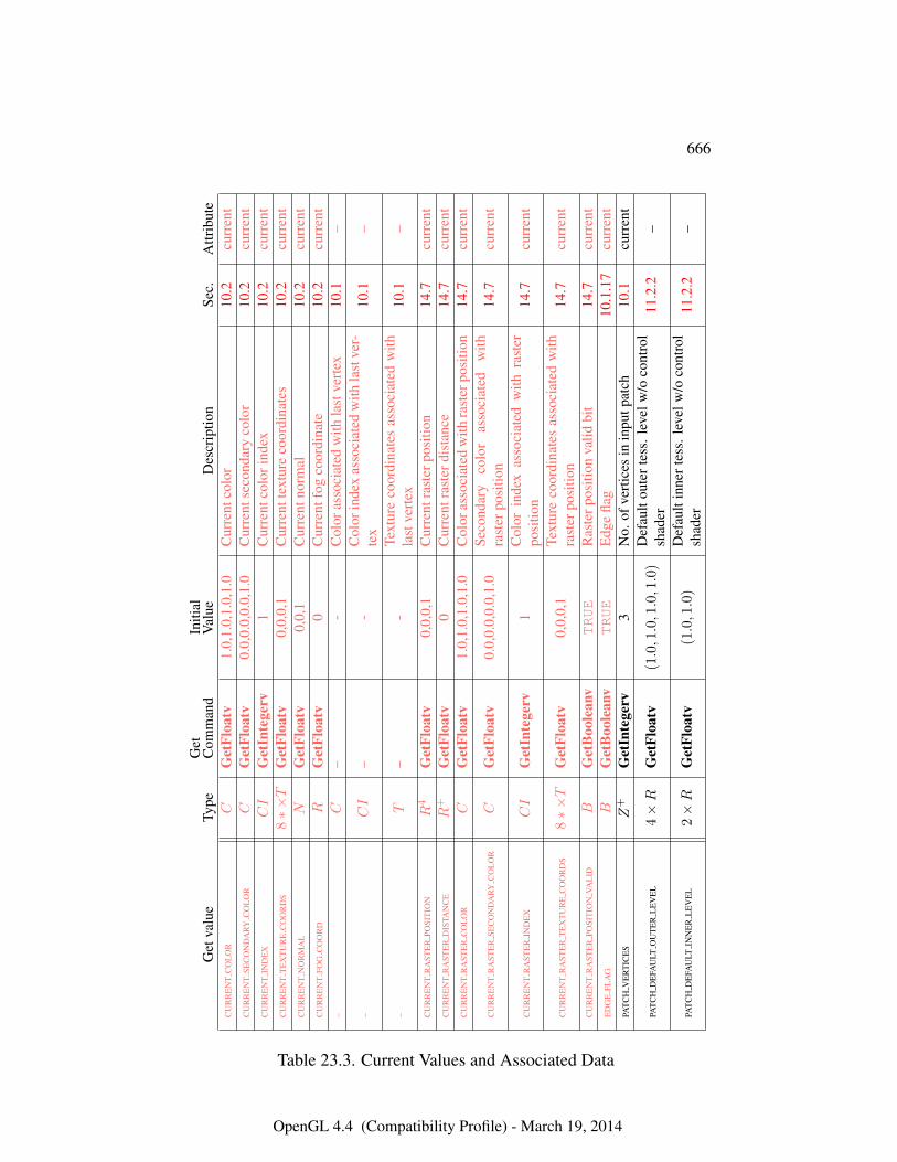
666
Get
valu
eTy
peG
etC
omm
and
Initi
alV
alue
Des
crip
tion
Sec.
Attr
ibut
eC
UR
RE
NT
CO
LO
RC
Get
Floa
tv1.
0,1.
0,1.
0,1.
0C
urre
ntco
lor
10.2
curr
ent
CU
RR
EN
TSE
CO
ND
ARY
CO
LO
RC
Get
Floa
tv0.
0,0.
0,0.
0,1.
0C
urre
ntse
cond
ary
colo
r10
.2cu
rren
tC
UR
RE
NT
IND
EX
CI
Get
Inte
gerv
1C
urre
ntco
lori
ndex
10.2
curr
ent
CU
RR
EN
TT
EX
TU
RE
CO
OR
DS
8∗×T
Get
Floa
tv0,
0,0,
1C
urre
ntte
xtur
eco
ordi
nate
s10
.2cu
rren
tC
UR
RE
NT
NO
RM
AL
NG
etFl
oatv
0,0,
1C
urre
ntno
rmal
10.2
curr
ent
CU
RR
EN
TFO
GC
OO
RD
RG
etFl
oatv
0C
urre
ntfo
gco
ordi
nate
10.2
curr
ent
–C
–-
Col
oras
soci
ated
with
last
vert
ex10
.1–
–CI
–-
Col
orin
dex
asso
ciat
edw
ithla
stve
r-te
x10
.1–
–T
–-
Text
ure
coor
dina
tes
asso
ciat
edw
ithla
stve
rtex
10.1
–
CU
RR
EN
TR
AST
ER
POSI
TIO
NR
4G
etFl
oatv
0,0,
0,1
Cur
rent
rast
erpo
sitio
n14
.7cu
rren
tC
UR
RE
NT
RA
STE
RD
ISTA
NC
ER
+G
etFl
oatv
0C
urre
ntra
ster
dist
ance
14.7
curr
ent
CU
RR
EN
TR
AST
ER
CO
LO
RC
Get
Floa
tv1.
0,1.
0,1.
0,1.
0C
olor
asso
ciat
edw
ithra
ster
posi
tion
14.7
curr
ent
CU
RR
EN
TR
AST
ER
SEC
ON
DA
RYC
OL
OR
CG
etFl
oatv
0.0,
0.0,
0.0,
1.0
Seco
ndar
yco
lor
asso
ciat
edw
ithra
ster
posi
tion
14.7
curr
ent
CU
RR
EN
TR
AST
ER
IND
EX
CI
Get
Inte
gerv
1C
olor
inde
xas
soci
ated
with
rast
erpo
sitio
n14
.7cu
rren
t
CU
RR
EN
TR
AST
ER
TE
XT
UR
EC
OO
RD
S8∗×T
Get
Floa
tv0,
0,0,
1Te
xtur
eco
ordi
nate
sas
soci
ated
with
rast
erpo
sitio
n14
.7cu
rren
t
CU
RR
EN
TR
AST
ER
POSI
TIO
NVA
LID
BG
etB
oole
anv
TRUE
Ras
terp
ositi
onva
lidbi
t14
.7cu
rren
tE
DG
EFL
AG
BG
etB
oole
anv
TRUE
Edg
efla
g10
.1.1
7cu
rren
tPA
TC
HV
ER
TIC
ES
Z+
Get
Inte
gerv
3N
o.of
vert
ices
inin
putp
atch
10.1
curr
ent
PAT
CH
DE
FAU
LTO
UT
ER
LE
VE
L4×R
Get
Floa
tv(1.0,1.0,1.0,1.0
)D
efau
ltou
tert
ess.
leve
lw/o
cont
rol
shad
er11
.2.2
–
PAT
CH
DE
FAU
LTIN
NE
RL
EV
EL
2×R
Get
Floa
tv(1.0,1.0
)D
efau
ltin
nert
ess.
leve
lw/o
cont
rol
shad
er11
.2.2
–
Table 23.3. Current Values and Associated Data
OpenGL 4.4 (Compatibility Profile) - March 19, 2014
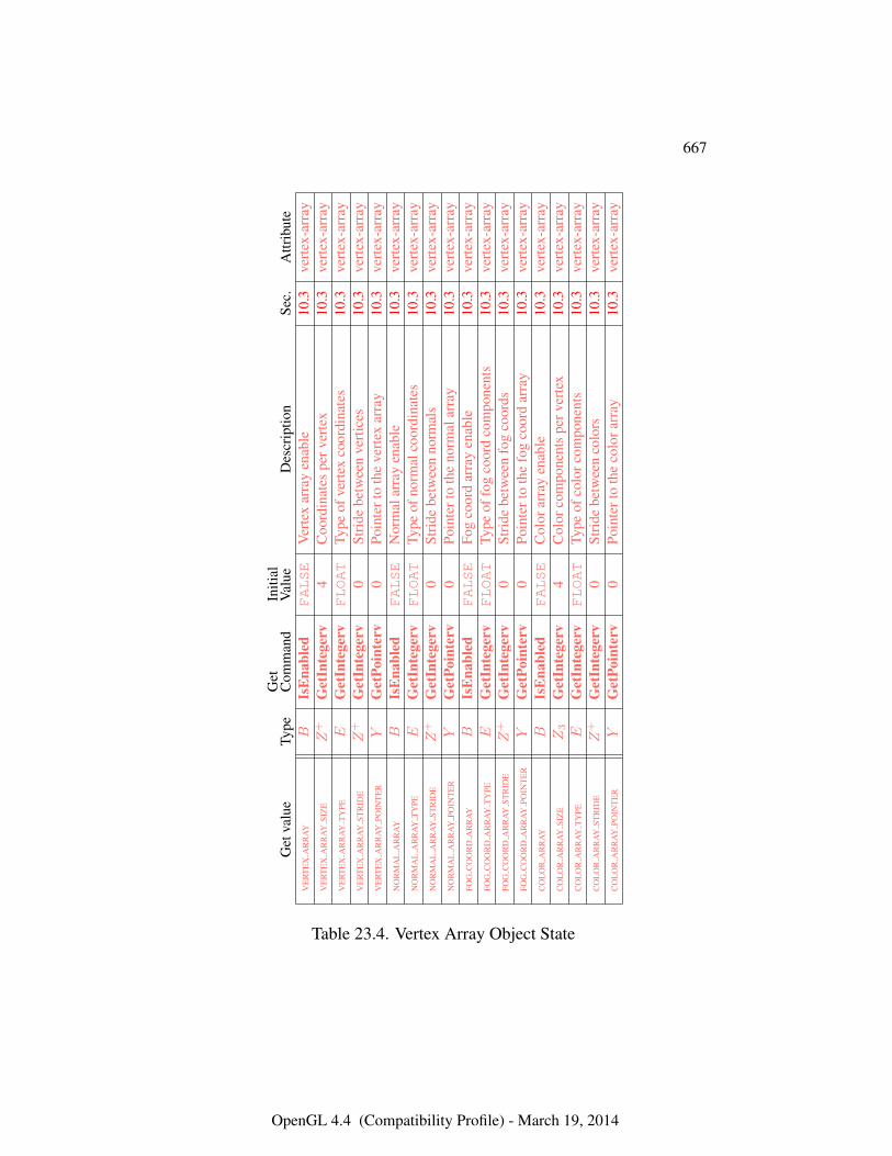
667
Get
valu
eTy
peG
etC
omm
and
Initi
alV
alue
Des
crip
tion
Sec.
Attr
ibut
eV
ER
TE
XA
RR
AY
BIs
Ena
bled
FALSE
Ver
tex
arra
yen
able
10.3
vert
ex-a
rray
VE
RT
EX
AR
RA
YSI
ZE
Z+
Get
Inte
gerv
4C
oord
inat
espe
rver
tex
10.3
vert
ex-a
rray
VE
RT
EX
AR
RA
YT
YPE
EG
etIn
tege
rvFLOAT
Type
ofve
rtex
coor
dina
tes
10.3
vert
ex-a
rray
VE
RT
EX
AR
RA
YST
RID
EZ
+G
etIn
tege
rv0
Stri
debe
twee
nve
rtic
es10
.3ve
rtex
-arr
ayV
ER
TE
XA
RR
AY
POIN
TE
RY
Get
Poin
terv
0Po
inte
rto
the
vert
exar
ray
10.3
vert
ex-a
rray
NO
RM
AL
AR
RA
YB
IsE
nabl
edFALSE
Nor
mal
arra
yen
able
10.3
vert
ex-a
rray
NO
RM
AL
AR
RA
YT
YPE
EG
etIn
tege
rvFLOAT
Type
ofno
rmal
coor
dina
tes
10.3
vert
ex-a
rray
NO
RM
AL
AR
RA
YST
RID
EZ
+G
etIn
tege
rv0
Stri
debe
twee
nno
rmal
s10
.3ve
rtex
-arr
ayN
OR
MA
LA
RR
AY
POIN
TE
RY
Get
Poin
terv
0Po
inte
rto
the
norm
alar
ray
10.3
vert
ex-a
rray
FOG
CO
OR
DA
RR
AY
BIs
Ena
bled
FALSE
Fog
coor
dar
ray
enab
le10
.3ve
rtex
-arr
ayFO
GC
OO
RD
AR
RA
YT
YPE
EG
etIn
tege
rvFLOAT
Type
offo
gco
ord
com
pone
nts
10.3
vert
ex-a
rray
FOG
CO
OR
DA
RR
AY
STR
IDE
Z+
Get
Inte
gerv
0St
ride
betw
een
fog
coor
ds10
.3ve
rtex
-arr
ayFO
GC
OO
RD
AR
RA
YPO
INT
ER
YG
etPo
inte
rv0
Poin
tert
oth
efo
gco
ord
arra
y10
.3ve
rtex
-arr
ayC
OL
OR
AR
RA
YB
IsE
nabl
edFALSE
Col
orar
ray
enab
le10
.3ve
rtex
-arr
ayC
OL
OR
AR
RA
YSI
ZE
Z3
Get
Inte
gerv
4C
olor
com
pone
nts
perv
erte
x10
.3ve
rtex
-arr
ayC
OL
OR
AR
RA
YT
YPE
EG
etIn
tege
rvFLOAT
Type
ofco
lorc
ompo
nent
s10
.3ve
rtex
-arr
ayC
OL
OR
AR
RA
YST
RID
EZ
+G
etIn
tege
rv0
Stri
debe
twee
nco
lors
10.3
vert
ex-a
rray
CO
LO
RA
RR
AY
POIN
TE
RY
Get
Poin
terv
0Po
inte
rto
the
colo
rarr
ay10
.3ve
rtex
-arr
ay
Table 23.4. Vertex Array Object State
OpenGL 4.4 (Compatibility Profile) - March 19, 2014
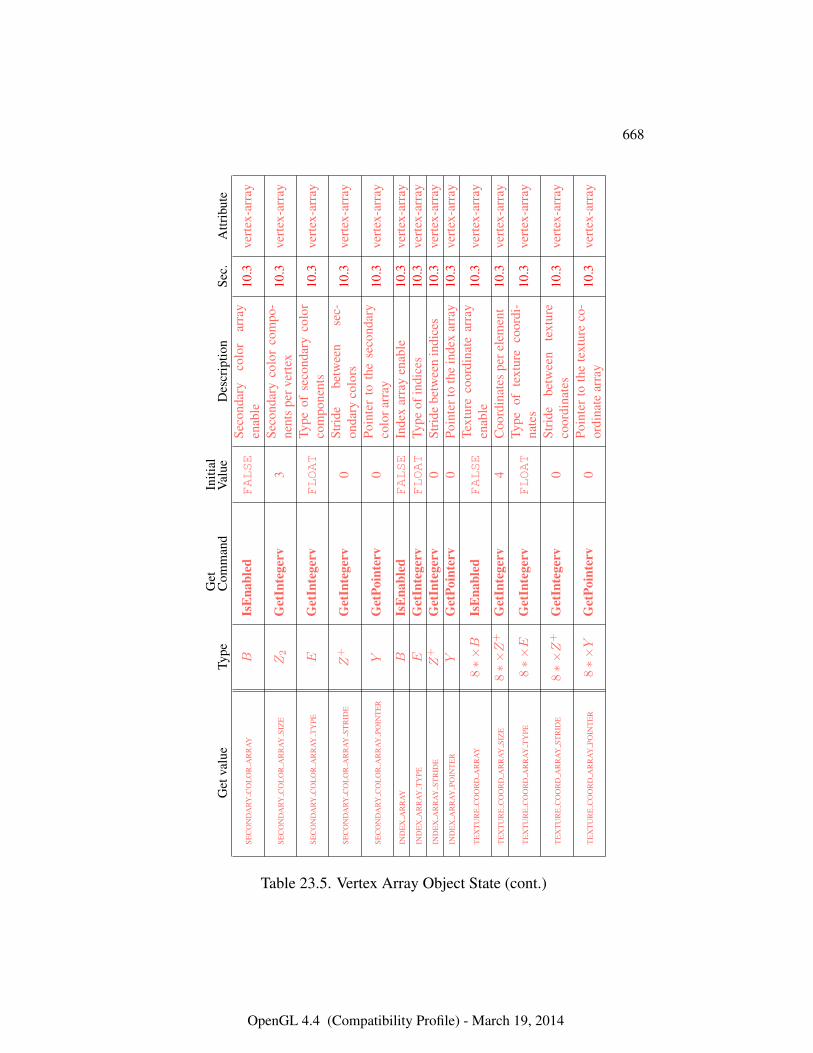
668
Get
valu
eTy
peG
etC
omm
and
Initi
alV
alue
Des
crip
tion
Sec.
Attr
ibut
e
SEC
ON
DA
RYC
OL
OR
AR
RA
YB
IsE
nabl
edFALSE
Seco
ndar
yco
lor
arra
yen
able
10.3
vert
ex-a
rray
SEC
ON
DA
RYC
OL
OR
AR
RA
YSI
ZE
Z2
Get
Inte
gerv
3Se
cond
ary
colo
rco
mpo
-ne
nts
perv
erte
x10
.3ve
rtex
-arr
ay
SEC
ON
DA
RYC
OL
OR
AR
RA
YT
YPE
EG
etIn
tege
rvFLOAT
Type
ofse
cond
ary
colo
rco
mpo
nent
s10
.3ve
rtex
-arr
ay
SEC
ON
DA
RYC
OL
OR
AR
RA
YST
RID
EZ
+G
etIn
tege
rv0
Stri
debe
twee
nse
c-on
dary
colo
rs10
.3ve
rtex
-arr
ay
SEC
ON
DA
RYC
OL
OR
AR
RA
YPO
INT
ER
YG
etPo
inte
rv0
Poin
ter
toth
ese
cond
ary
colo
rarr
ay10
.3ve
rtex
-arr
ay
IND
EX
AR
RA
YB
IsE
nabl
edFALSE
Inde
xar
ray
enab
le10
.3ve
rtex
-arr
ayIN
DE
XA
RR
AY
TY
PEE
Get
Inte
gerv
FLOAT
Type
ofin
dice
s10
.3ve
rtex
-arr
ayIN
DE
XA
RR
AY
STR
IDE
Z+
Get
Inte
gerv
0St
ride
betw
een
indi
ces
10.3
vert
ex-a
rray
IND
EX
AR
RA
YPO
INT
ER
YG
etPo
inte
rv0
Poin
tert
oth
ein
dex
arra
y10
.3ve
rtex
-arr
ay
TE
XT
UR
EC
OO
RD
AR
RA
Y8∗×B
IsE
nabl
edFALSE
Text
ure
coor
dina
tear
ray
enab
le10
.3ve
rtex
-arr
ay
TE
XT
UR
EC
OO
RD
AR
RA
YSI
ZE
8∗×Z
+G
etIn
tege
rv4
Coo
rdin
ates
pere
lem
ent
10.3
vert
ex-a
rray
TE
XT
UR
EC
OO
RD
AR
RA
YT
YPE
8∗×E
Get
Inte
gerv
FLOAT
Type
ofte
xtur
eco
ordi
-na
tes
10.3
vert
ex-a
rray
TE
XT
UR
EC
OO
RD
AR
RA
YST
RID
E8∗×Z
+G
etIn
tege
rv0
Stri
debe
twee
nte
xtur
eco
ordi
nate
s10
.3ve
rtex
-arr
ay
TE
XT
UR
EC
OO
RD
AR
RA
YPO
INT
ER
8∗×Y
Get
Poin
terv
0Po
inte
rto
the
text
ure
co-
ordi
nate
arra
y10
.3ve
rtex
-arr
ay
Table 23.5. Vertex Array Object State (cont.)
OpenGL 4.4 (Compatibility Profile) - March 19, 2014
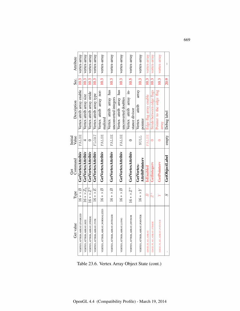
669
Get
valu
eTy
peG
etC
omm
and
Initi
alV
alue
Des
crip
tion
Sec.
Attr
ibut
eV
ER
TE
XA
TT
RIB
AR
RA
YE
NA
BL
ED
16∗×B
Get
Vert
exA
ttri
biv
FALSE
Ver
tex
attr
ibar
ray
enab
le10
.3ve
rtex
-arr
ayV
ER
TE
XA
TT
RIB
AR
RA
YSI
ZE
16∗×Z5
Get
Vert
exA
ttri
biv
4V
erte
xat
trib
arra
ysi
ze10
.3ve
rtex
-arr
ayV
ER
TE
XA
TT
RIB
AR
RA
YST
RID
E16∗×Z
+G
etVe
rtex
Att
ribi
v0
Ver
tex
attr
ibar
ray
stri
de10
.3ve
rtex
-arr
ayV
ER
TE
XA
TT
RIB
AR
RA
YT
YPE
16∗×E
Get
Vert
exA
ttri
biv
FLOAT
Ver
tex
attr
ibar
ray
type
10.3
vert
ex-a
rray
VE
RT
EX
AT
TR
IBA
RR
AY
NO
RM
AL
IZE
D16∗×B
Get
Vert
exA
ttri
biv
FALSE
Ver
tex
attr
ibar
ray
nor-
mal
ized
10.3
vert
ex-a
rray
VE
RT
EX
AT
TR
IBA
RR
AY
INT
EG
ER
16∗×B
Get
Vert
exA
ttri
biv
FALSE
Ver
tex
attr
ibar
ray
has
unco
nver
ted
inte
gers
10.3
vert
ex-a
rray
VE
RT
EX
AT
TR
IBA
RR
AY
LO
NG
16∗×B
Get
Vert
exA
ttri
biv
FALSE
Ver
tex
attr
ibar
ray
has
unco
nver
ted
doub
les
10.3
vert
ex-a
rray
VE
RT
EX
AT
TR
IBA
RR
AY
DIV
ISO
R16∗×Z
+G
etVe
rtex
Att
ribi
v0
Ver
tex
attr
ibar
ray
in-
stan
cedi
viso
r10
.5ve
rtex
-arr
ay
VE
RT
EX
AT
TR
IBA
RR
AY
POIN
TE
R16∗×Y
Get
Vert
ex-
Att
ribP
oint
erv
NULL
Ver
tex
attr
ibar
ray
poin
ter
10.3
vert
ex-a
rray
ED
GE
FLA
GA
RR
AY
BIs
Ena
bled
FALSE
Edg
efla
gar
ray
enab
le10
.3ve
rtex
-arr
ayE
DG
EFL
AG
AR
RA
YST
RID
EZ
+G
etIn
tege
rv0
Stri
debe
twee
ned
gefla
gs10
.3ve
rtex
-arr
ay
ED
GE
FLA
GA
RR
AY
POIN
TE
RY
Get
Poin
terv
0Po
inte
rto
the
edge
flag
arra
y10
.3ve
rtex
-arr
ay
–S
Get
Obj
ectL
abel
empt
yD
ebug
labe
l20
.9–
Table 23.6. Vertex Array Object State (cont.)
OpenGL 4.4 (Compatibility Profile) - March 19, 2014
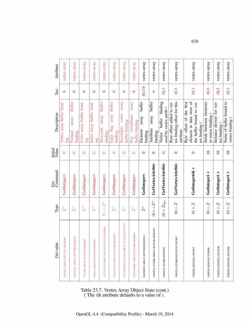
670
Get
valu
eTy
peG
etC
omm
and
Initi
alV
alue
Des
crip
tion
Sec.
Attr
ibut
e
VE
RT
EX
AR
RA
YB
UFF
ER
BIN
DIN
GZ
+G
etIn
tege
rv0
Ver
tex
arra
ybu
ffer
bind
-in
g6
vert
ex-a
rray
NO
RM
AL
AR
RA
YB
UFF
ER
BIN
DIN
GZ
+G
etIn
tege
rv0
Nor
mal
arra
ybu
ffer
bind
ing
6ve
rtex
-arr
ay
CO
LO
RA
RR
AY
BU
FFE
RB
IND
ING
Z+
Get
Inte
gerv
0C
olor
arra
ybu
ffer
bind
-in
g6
vert
ex-a
rray
IND
EX
AR
RA
YB
UFF
ER
BIN
DIN
GZ
+G
etIn
tege
rv0
Inde
xar
ray
buff
erbi
nd-
ing
6ve
rtex
-arr
ay
TE
XT
UR
EC
OO
RD
AR
RA
YB
UFF
ER
BIN
DIN
G8∗×Z
+G
etIn
tege
rv0
Texc
oord
arra
ybu
ffer
bind
ing
6ve
rtex
-arr
ay
ED
GE
FLA
GA
RR
AY
BU
FFE
RB
IND
ING
Z+
Get
Inte
gerv
0E
dge
flag
arra
ybu
ffer
bind
ing
6ve
rtex
-arr
ay
SEC
ON
DA
RYC
OL
OR
AR
RA
YB
UFF
ER
BIN
DIN
GZ
+G
etIn
tege
rv0
Seco
ndar
yco
lor
arra
ybu
ffer
bind
ing
6ve
rtex
-arr
ay
FOG
CO
OR
DA
RR
AY
BU
FFE
RB
IND
ING
Z+
Get
Inte
gerv
0Fo
gco
ordi
nate
arra
ybu
ffer
bind
ing
6ve
rtex
-arr
ay
EL
EM
EN
TA
RR
AY
BU
FFE
RB
IND
ING
Z+
Get
Inte
gerv
0E
lem
ent
arra
ybu
ffer
bind
ing
10.3
.9ve
rtex
-arr
ay
VE
RT
EX
AT
TR
IBA
RR
AY
BU
FFE
RB
IND
ING
16∗×Z
+G
etVe
rtex
Att
ribi
v0
Attr
ibut
ear
ray
buff
erbi
ndin
g6
vert
ex-a
rray
VE
RT
EX
AT
TR
IBB
IND
ING
16×Z16∗
Get
Vert
exA
ttri
biv
i†V
erte
xbu
ffer
bind
ing
used
byve
rtex
attr
ibi
10.3
vert
ex-a
rray
VE
RT
EX
AT
TR
IBR
EL
AT
IVE
OFF
SET
16×Z
Get
Vert
exA
ttri
biv
0B
yte
offs
etad
ded
tove
r-te
xbi
ndin
gof
fset
fort
his
attr
ibut
e10
.3ve
rtex
-arr
ay
VE
RT
EX
BIN
DIN
GO
FFSE
T16×Z
Get
Inte
ger6
4iv
0
Byt
eof
fset
ofth
efir
stel
emen
tin
data
stor
eof
the
buff
erbo
und
tove
r-te
xbi
ndin
gi
10.3
vert
ex-a
rray
VE
RT
EX
BIN
DIN
GST
RID
E16×Z
Get
Inte
geri
v16
Stri
debe
twee
nel
emen
tsin
vert
exbi
ndin
gi
10.3
vert
ex-a
rray
VE
RT
EX
BIN
DIN
GD
IVIS
OR
16×Z
Get
Inte
geri
v16
Inst
ance
divi
sor
for
ver-
tex
bind
ingi
10.3
vert
ex-a
rray
VE
RT
EX
BIN
DIN
GB
UFF
ER
16×Z
Get
Inte
geri
v16
Nam
eof
buff
erbo
und
tove
rtex
bind
ingi
10.3
vert
ex-a
rray
Table 23.7. Vertex Array Object State (cont.)† The ith attribute defaults to a value of i.
OpenGL 4.4 (Compatibility Profile) - March 19, 2014
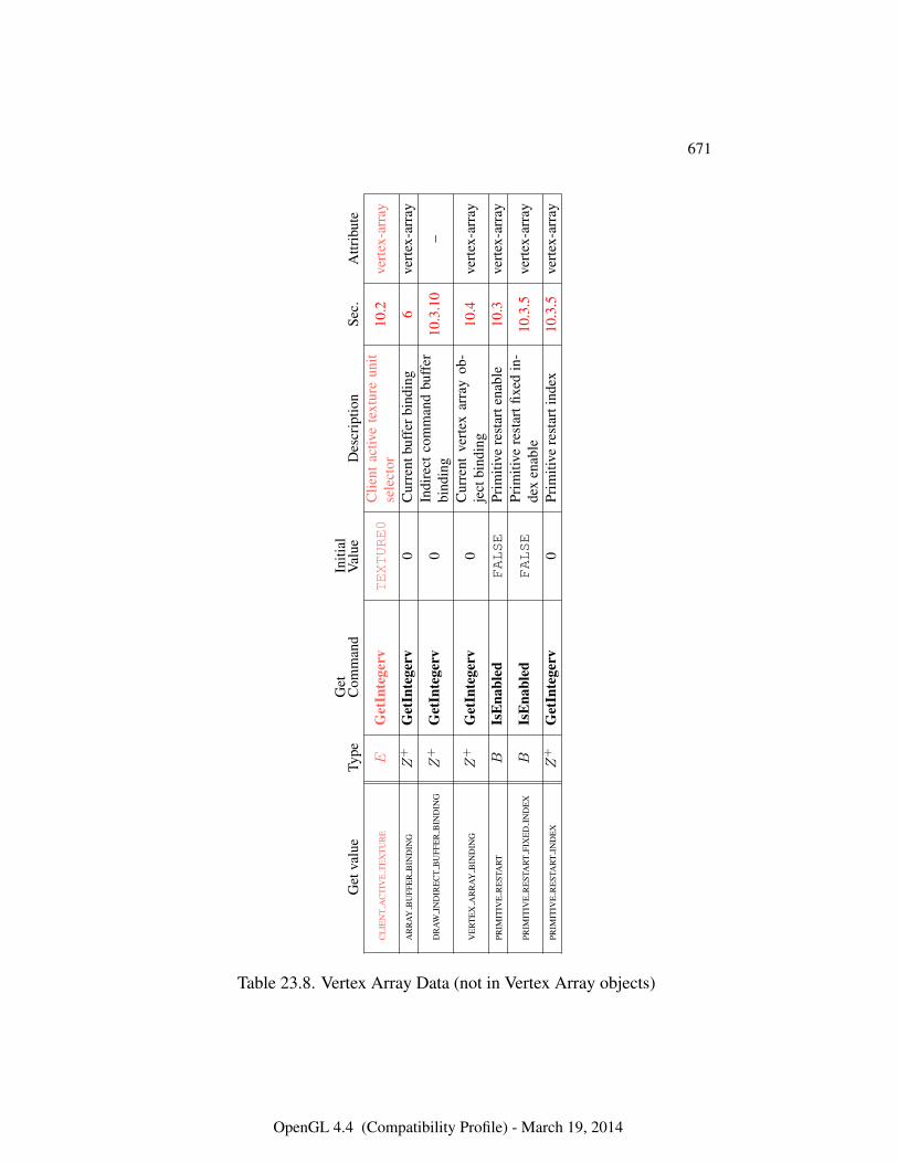
671
Get
valu
eTy
peG
etC
omm
and
Initi
alV
alue
Des
crip
tion
Sec.
Attr
ibut
e
CL
IEN
TA
CT
IVE
TE
XT
UR
EE
Get
Inte
gerv
TEXTURE0
Clie
ntac
tive
text
ure
unit
sele
ctor
10.2
vert
ex-a
rray
AR
RA
YB
UFF
ER
BIN
DIN
GZ
+G
etIn
tege
rv0
Cur
rent
buff
erbi
ndin
g6
vert
ex-a
rray
DR
AW
IND
IRE
CT
BU
FFE
RB
IND
ING
Z+
Get
Inte
gerv
0In
dire
ctco
mm
and
buff
erbi
ndin
g10
.3.1
0–
VE
RT
EX
AR
RA
YB
IND
ING
Z+
Get
Inte
gerv
0C
urre
ntve
rtex
arra
yob
-je
ctbi
ndin
g10
.4ve
rtex
-arr
ay
PRIM
ITIV
ER
EST
AR
TB
IsE
nabl
edFALSE
Prim
itive
rest
arte
nabl
e10
.3ve
rtex
-arr
ay
PRIM
ITIV
ER
EST
AR
TFI
XE
DIN
DE
XB
IsE
nabl
edFALSE
Prim
itive
rest
artfi
xed
in-
dex
enab
le10
.3.5
vert
ex-a
rray
PRIM
ITIV
ER
EST
AR
TIN
DE
XZ
+G
etIn
tege
rv0
Prim
itive
rest
arti
ndex
10.3
.5ve
rtex
-arr
ay
Table 23.8. Vertex Array Data (not in Vertex Array objects)
OpenGL 4.4 (Compatibility Profile) - March 19, 2014
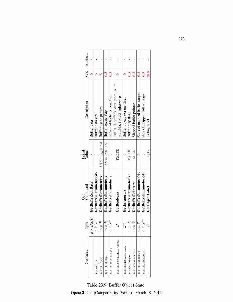
672
Get
valu
eTy
peG
etC
omm
and
Initi
alV
alue
Des
crip
tion
Sec.
Attr
ibut
e–
n×BMU
Get
Buf
ferS
ubD
ata
-B
uffe
rdat
a6
-B
UFF
ER
SIZ
En×Z
+G
etB
uffe
rPar
amet
eri6
4v0
Buf
ferd
ata
size
6-
BU
FFE
RU
SAG
En×E
Get
Buf
ferP
aram
eter
ivSTATIC_DRAW
Buf
feru
sage
patte
rn6
-B
UFF
ER
AC
CE
SSn×E
Get
Buf
ferP
aram
eter
ivREAD_WRITE
Buf
fera
cces
sfla
g6.
3-
BU
FFE
RA
CC
ESS
FLA
GS
n×Z
+G
etB
uffe
rPar
amet
eriv
0E
xten
ded
buff
erac
cess
flag
6.3
-
BU
FFE
RIM
MU
TAB
LE
STO
RA
GE
BG
etB
oole
anv
FALSE
TRUE
ifbu
ffer
’sda
tast
ore
isim
-m
utab
le,FALSE
othe
rwis
e6
-
BU
FFE
RST
OR
AG
EFL
AG
SZ
+G
etIn
tege
ruiv
0B
uffe
robj
ects
tora
gefla
gs6
-B
UFF
ER
MA
PPE
Dn×B
Get
Buf
ferP
aram
eter
ivFALSE
Buf
ferm
apfla
g6.
3-
BU
FFE
RM
AP
POIN
TE
Rn×Y
Get
Buf
ferP
oint
erv
NULL
Map
ped
buff
erpo
inte
r6.
3-
BU
FFE
RM
AP
OFF
SET
n×Z
+G
etB
uffe
rPar
amet
eri6
4v0
Star
tofm
appe
dbu
ffer
rang
e6.
3-
BU
FFE
RM
AP
LE
NG
TH
n×Z
+G
etB
uffe
rPar
amet
eri6
4v0
Size
ofm
appe
dbu
ffer
rang
e6.
3-
–S
Get
Obj
ectL
abel
empt
yD
ebug
labe
l20
.9–
Table 23.9. Buffer Object State
OpenGL 4.4 (Compatibility Profile) - March 19, 2014
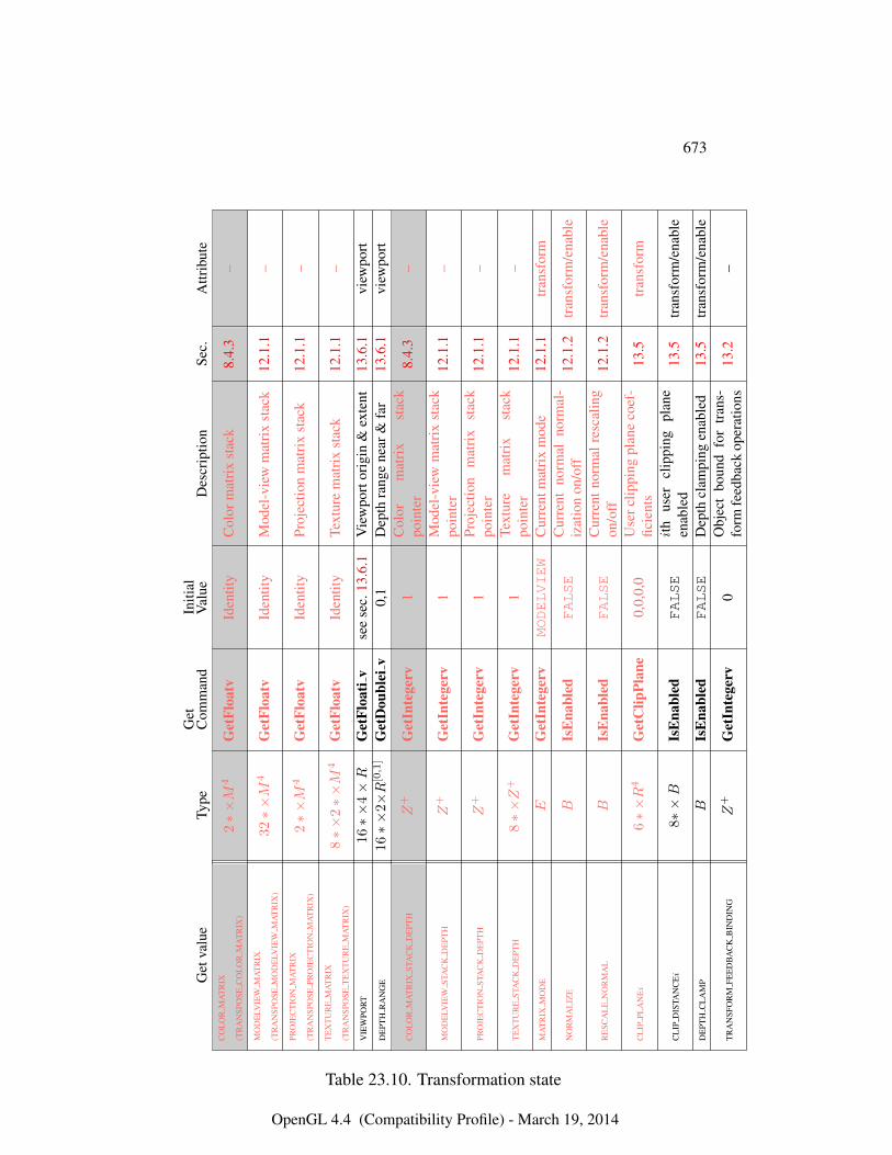
673
Get
valu
eTy
peG
etC
omm
and
Initi
alV
alue
Des
crip
tion
Sec.
Attr
ibut
eC
OL
OR
MA
TR
IX
(TR
AN
SPO
SEC
OL
OR
MA
TR
IX)
2∗×M
4G
etFl
oatv
Iden
tity
Col
orm
atri
xst
ack
8.4.
3–
MO
DE
LVIE
WM
AT
RIX
(TR
AN
SPO
SEM
OD
ELV
IEW
MA
TR
IX)
32∗×M
4G
etFl
oatv
Iden
tity
Mod
el-v
iew
mat
rix
stac
k12
.1.1
–
PRO
JEC
TIO
NM
AT
RIX
(TR
AN
SPO
SEPR
OJE
CT
ION
MA
TR
IX)
2∗×M
4G
etFl
oatv
Iden
tity
Proj
ectio
nm
atri
xst
ack
12.1
.1–
TE
XT
UR
EM
AT
RIX
(TR
AN
SPO
SET
EX
TU
RE
MA
TR
IX)
8∗×
2∗×M
4G
etFl
oatv
Iden
tity
Text
ure
mat
rix
stac
k12
.1.1
–
VIE
WPO
RT
16∗×
4×R
Get
Floa
tiv
see
sec.
13.6
.1V
iew
port
orig
in&
exte
nt13
.6.1
view
port
DE
PTH
RA
NG
E16∗×
2×R
[0,1]
Get
Dou
blei
v0,
1D
epth
rang
ene
ar&
far
13.6
.1vi
ewpo
rt
CO
LO
RM
AT
RIX
STA
CK
DE
PTH
Z+
Get
Inte
gerv
1C
olor
mat
rix
stac
kpo
inte
r8.
4.3
–
MO
DE
LVIE
WST
AC
KD
EPT
HZ
+G
etIn
tege
rv1
Mod
el-v
iew
mat
rix
stac
kpo
inte
r12
.1.1
–
PRO
JEC
TIO
NST
AC
KD
EPT
HZ
+G
etIn
tege
rv1
Proj
ectio
nm
atri
xst
ack
poin
ter
12.1
.1–
TE
XT
UR
EST
AC
KD
EPT
H8∗×Z
+G
etIn
tege
rv1
Text
ure
mat
rix
stac
kpo
inte
r12
.1.1
–
MA
TR
IXM
OD
EE
Get
Inte
gerv
MODELVIEW
Cur
rent
mat
rix
mod
e12
.1.1
tran
sfor
m
NO
RM
AL
IZE
BIs
Ena
bled
FALSE
Cur
rent
norm
alno
rmal
-iz
atio
non
/off
12.1
.2tr
ansf
orm
/ena
ble
RE
SCA
LE
NO
RM
AL
BIs
Ena
bled
FALSE
Cur
rent
norm
alre
scal
ing
on/o
ff12
.1.2
tran
sfor
m/e
nabl
e
CL
IPPL
AN
Ei
6∗×R
4G
etC
lipPl
ane
0,0,
0,0
Use
rclip
ping
plan
eco
ef-
ficie
nts
13.5
tran
sfor
m
CL
IPD
ISTA
NC
Ei
8∗×B
IsE
nabl
edFALSE
ith
user
clip
ping
plan
een
able
d13
.5tr
ansf
orm
/ena
ble
DE
PTH
CL
AM
PB
IsE
nabl
edFALSE
Dep
thcl
ampi
ngen
able
d13
.5tr
ansf
orm
/ena
ble
TR
AN
SFO
RM
FEE
DB
AC
KB
IND
ING
Z+
Get
Inte
gerv
0O
bjec
tbo
und
for
tran
s-fo
rmfe
edba
ckop
erat
ions
13.2
–
Table 23.10. Transformation state
OpenGL 4.4 (Compatibility Profile) - March 19, 2014

674
Get
valu
eTy
peG
etC
omm
and
Initi
alV
alue
Des
crip
tion
Sec.
Attr
ibut
eFO
GC
OL
OR
CG
etFl
oatv
0.0,
0.0,
0.0,
0.0F
ogco
lor
16.4
fog
FOG
IND
EX
CI
Get
Floa
tv0
Fog
inde
x16
.4fo
gFO
GD
EN
SIT
YR
Get
Floa
tv1.
0E
xpon
entia
lfog
dens
ity16
.4fo
gFO
GST
AR
TR
Get
Floa
tv0.
0L
inea
rfog
star
t16
.4fo
gFO
GE
ND
RG
etFl
oatv
1.0
Lin
earf
ogen
d16
.4fo
gFO
GM
OD
EE
Get
Inte
gerv
EXP
Fog
mod
e16
.4fo
gFO
GB
IsE
nabl
edFALSE
True
iffo
gen
able
d16
.4fo
g/en
able
FOG
CO
OR
DSR
CE
Get
Inte
gerv
FRAGMENT_-
DEPTH
Sour
ceof
coor
dina
tefo
rfo
gca
lcul
atio
n16
.4fo
g
CO
LO
RSU
MB
IsE
nabl
edFALSE
True
ifco
lors
umen
able
d16
.3fo
g/en
able
SHA
DE
MO
DE
LE
Get
Inte
gerv
SMOOTH
Shad
eMod
else
tting
13.4
light
ing
CL
AM
PV
ER
TE
XC
OL
OR
EG
etIn
tege
rvTRUE
Ver
tex
colo
rcla
mpi
ng13
.1lig
htin
g/en
able
CL
AM
PFR
AG
ME
NT
CO
LO
RE
Get
Inte
gerv
FIXED_-
ONLY
Frag
men
tcol
orcl
ampi
ng18
.1.1
colo
r-bu
ffer
/ena
ble
CL
AM
PR
EA
DC
OL
OR
EG
etIn
tege
rvFIXED_-
ONLY
Rea
dco
lorc
lam
ping
18.2
.8co
lor-
buff
er/e
nabl
e
PRO
VO
KIN
GV
ER
TE
XE
Get
Inte
gerv
LAST_-
VERTEX_-
CONVENTIONPr
ovok
ing
vert
exco
n-ve
ntio
n13
.4lig
htin
g
Table 23.11. Coloring
OpenGL 4.4 (Compatibility Profile) - March 19, 2014
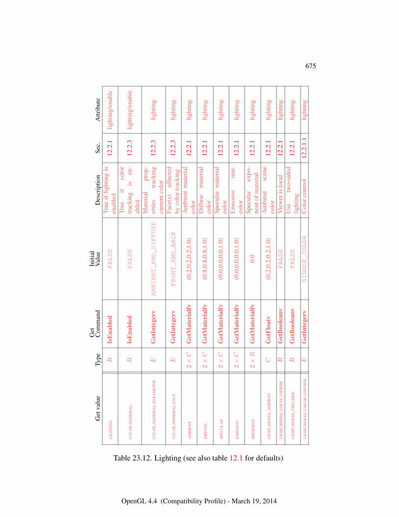
675
Get
valu
eTy
peG
etC
omm
and
Initi
alV
alue
Des
crip
tion
Sec.
Attr
ibut
e
LIG
HT
ING
BIs
Ena
bled
FALSE
True
iflig
htin
gis
enab
led
12.2
.1lig
htin
g/en
able
CO
LO
RM
AT
ER
IAL
BIs
Ena
bled
FALSE
True
ifco
lor
trac
king
isen
-ab
led
12.2
.3lig
htin
g/en
able
CO
LO
RM
AT
ER
IAL
PAR
AM
ET
ER
EG
etIn
tege
rvAMBIENT_AND_DIFFUSE
Mat
eria
lpr
op-
ertie
str
acki
ngcu
rren
tcol
or12
.2.3
light
ing
CO
LO
RM
AT
ER
IAL
FAC
EE
Get
Inte
gerv
FRONT_AND_BACK
Face
(s)
affe
cted
byco
lort
rack
ing
12.2
.3lig
htin
g
AM
BIE
NT
2×C
Get
Mat
eria
lfv(0
.2,0
.2,0
.2,1
.0)
Am
bien
tm
ater
ial
colo
r12
.2.1
light
ing
DIF
FUSE
2×C
Get
Mat
eria
lfv(0
.8,0
.8,0
.8,1
.0)
Diff
use
mat
eria
lco
lor
12.2
.1lig
htin
g
SPE
CU
LA
R2×C
Get
Mat
eria
lfv(0
.0,0
.0,0
.0,1
.0)
Spec
ular
mat
eria
lco
lor
12.2
.1lig
htin
g
EM
ISSI
ON
2×C
Get
Mat
eria
lfv(0
.0,0
.0,0
.0,1
.0)
Em
issi
vem
at.
colo
r12
.2.1
light
ing
SHIN
INE
SS2×R
Get
Mat
eria
lfv0.
0Sp
ecul
arex
po-
nent
ofm
ater
ial
12.2
.1lig
htin
g
LIG
HT
MO
DE
LA
MB
IEN
TC
Get
Floa
tv(0
.2,0
.2,0
.2,1
.0)
Am
bien
tsc
ene
colo
r12
.2.1
light
ing
LIG
HT
MO
DE
LL
OC
AL
VIE
WE
RB
Get
Boo
lean
vFALSE
Vie
wer
islo
cal
12.2
.1lig
htin
g
LIG
HT
MO
DE
LT
WO
SID
EB
Get
Boo
lean
vFALSE
Use
two-
side
dlig
htin
g12
.2.1
light
ing
LIG
HT
MO
DE
LC
OL
OR
CO
NT
RO
LE
Get
Inte
gerv
SINGLE_COLOR
Col
orco
ntro
l12
.2.1
.1lig
htin
g
Table 23.12. Lighting (see also table 12.1 for defaults)
OpenGL 4.4 (Compatibility Profile) - March 19, 2014
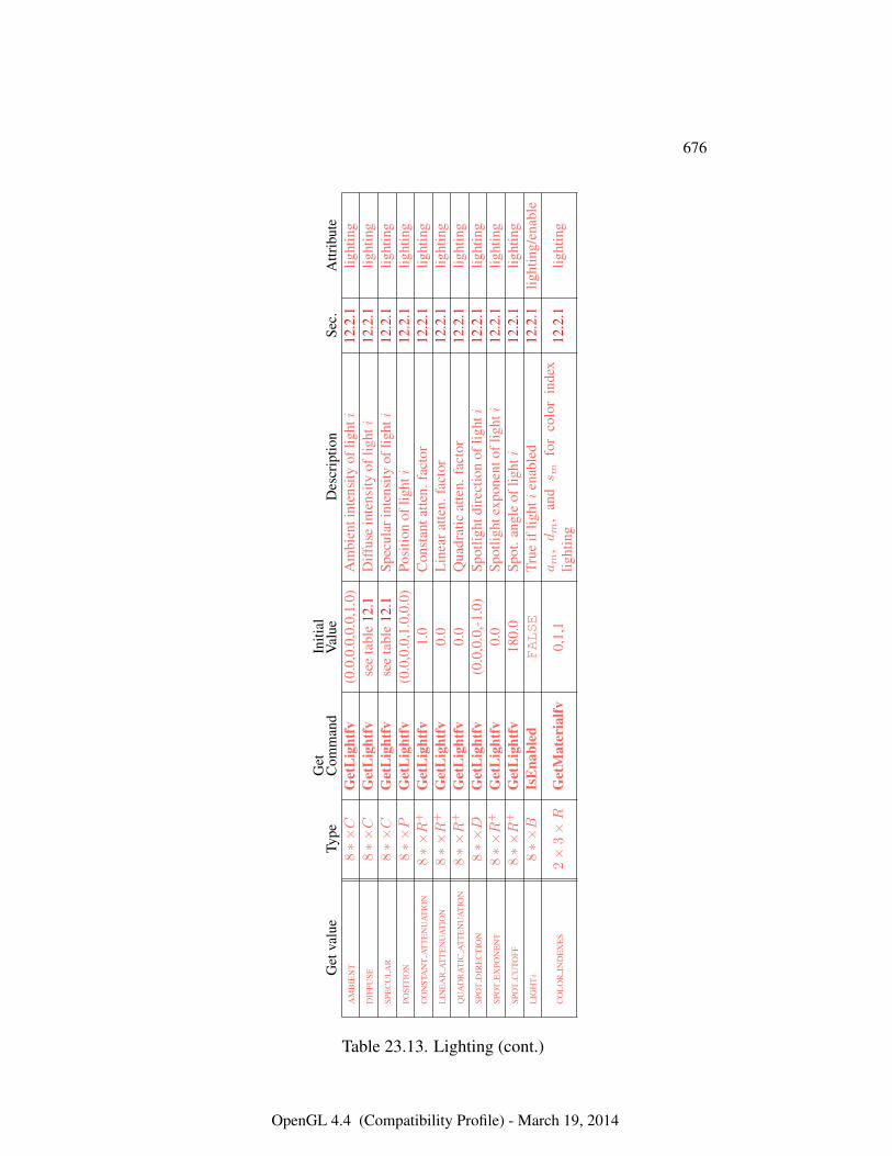
676
Get
valu
eTy
peG
etC
omm
and
Initi
alV
alue
Des
crip
tion
Sec.
Attr
ibut
eA
MB
IEN
T8∗×C
Get
Lig
htfv
(0.0
,0.0
,0.0
,1.0
)A
mbi
enti
nten
sity
oflig
hti
12.2
.1lig
htin
gD
IFFU
SE8∗×C
Get
Lig
htfv
see
tabl
e12
.1D
iffus
ein
tens
ityof
lighti
12.2
.1lig
htin
gSP
EC
UL
AR
8∗×C
Get
Lig
htfv
see
tabl
e12
.1Sp
ecul
arin
tens
ityof
lighti
12.2
.1lig
htin
gPO
SIT
ION
8∗×P
Get
Lig
htfv
(0.0
,0.0
,1.0
,0.0
)Po
sitio
nof
lighti
12.2
.1lig
htin
gC
ON
STA
NT
AT
TE
NU
AT
ION
8∗×R
+G
etL
ight
fv1.
0C
onst
anta
tten.
fact
or12
.2.1
light
ing
LIN
EA
RA
TT
EN
UA
TIO
N8∗×R
+G
etL
ight
fv0.
0L
inea
ratte
n.fa
ctor
12.2
.1lig
htin
gQ
UA
DR
AT
ICA
TT
EN
UA
TIO
N8∗×R
+G
etL
ight
fv0.
0Q
uadr
atic
atte
n.fa
ctor
12.2
.1lig
htin
gSP
OT
DIR
EC
TIO
N8∗×D
Get
Lig
htfv
(0.0
,0.0
,-1.0
)Sp
otlig
htdi
rect
ion
oflig
hti
12.2
.1lig
htin
gSP
OT
EX
PON
EN
T8∗×R
+G
etL
ight
fv0.
0Sp
otlig
htex
pone
ntof
lighti
12.2
.1lig
htin
gSP
OT
CU
TOFF
8∗×R
+G
etL
ight
fv18
0.0
Spot
.ang
leof
lighti
12.2
.1lig
htin
gL
IGH
Ti
8∗×B
IsE
nabl
edFALSE
True
iflig
hti
enab
led
12.2
.1lig
htin
g/en
able
CO
LO
RIN
DE
XE
S2×
3×R
Get
Mat
eria
lfv0,
1,1
am
,dm
,an
ds m
for
colo
rin
dex
light
ing
12.2
.1lig
htin
g
Table 23.13. Lighting (cont.)
OpenGL 4.4 (Compatibility Profile) - March 19, 2014
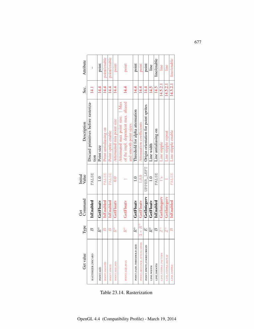
677
Get
valu
eTy
peG
etC
omm
and
Initi
alV
alue
Des
crip
tion
Sec.
Attr
ibut
e
RA
STE
RIZ
ER
DIS
CA
RD
BIs
Ena
bled
FALSE
Dis
card
prim
itive
sbe
fore
rast
eriz
a-tio
n14
.1–
POIN
TSI
ZE
R+
Get
Floa
tv1.
0Po
ints
ize
14.4
poin
tPO
INT
SMO
OT
HB
IsE
nabl
edFALSE
Poin
tant
ialia
sing
on14
.4po
int/e
nabl
ePO
INT
SPR
ITE
BIs
Ena
bled
FALSE
Poin
tspr
iteen
able
14.4
poin
t/ena
ble
POIN
TSI
ZE
MIN
R+
Get
Floa
tv0.
0A
ttenu
ated
min
poin
tsiz
e14
.4po
int
POIN
TSI
ZE
MA
XR
+G
etFl
oatv
†A
ttenu
ated
max
poin
tsi
ze.†
Max
ofth
eim
pl.d
epen
dent
max
.alia
sed
and
smoo
thpo
ints
izes
.14
.4po
int
POIN
TFA
DE
TH
RE
SHO
LD
SIZ
ER
+G
etFl
oatv
1.0
Thr
esho
ldfo
ralp
haat
tenu
atio
n14
.4po
int
POIN
TD
ISTA
NC
EA
TT
EN
UA
TIO
N3×R
+G
etFl
oatv
1,0,
0A
ttenu
atio
nco
effic
ient
s14
.4po
int
POIN
TSP
RIT
EC
OO
RD
OR
IGIN
EG
etIn
tege
rvUPPER_LEFT
Ori
gin
orie
ntat
ion
forp
oint
spri
tes
14.4
poin
tL
INE
WID
TH
R+
Get
Floa
tv1.
0L
ine
wid
th14
.5lin
eL
INE
SMO
OT
HB
IsE
nabl
edFALSE
Lin
ean
tialia
sing
on14
.5lin
e/en
able
LIN
EST
IPPL
EPA
TT
ER
NZ
+G
etIn
tege
rv1’
sL
ine
stip
ple
14.5
.2.1
line
LIN
EST
IPPL
ER
EPE
AT
Z+
Get
Inte
gerv
1L
ine
stip
ple
repe
at14
.5.2
.1lin
eL
INE
STIP
PLE
BIs
Ena
bled
FALSE
Lin
est
ippl
een
able
14.5
.2.1
line/
enab
le
Table 23.14. Rasterization
OpenGL 4.4 (Compatibility Profile) - March 19, 2014
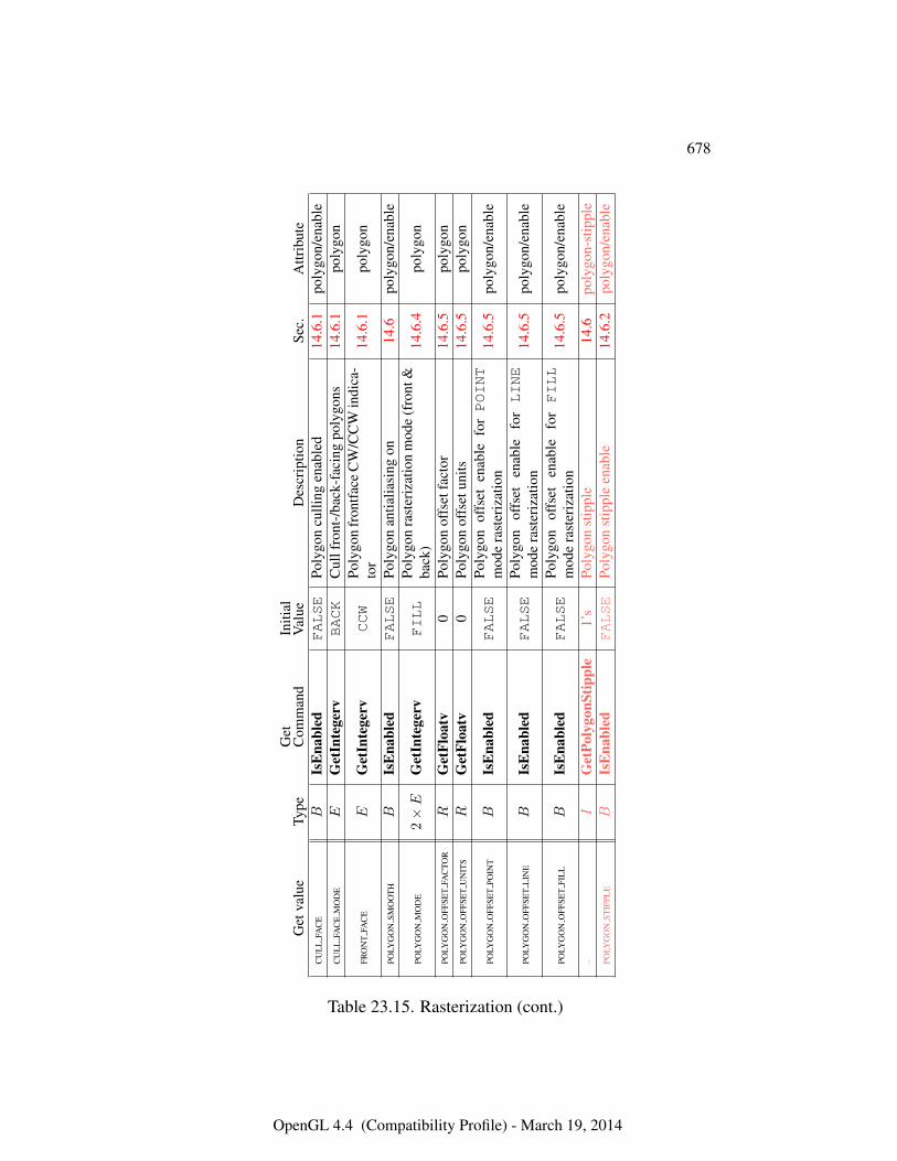
678
Get
valu
eTy
peG
etC
omm
and
Initi
alV
alue
Des
crip
tion
Sec.
Attr
ibut
eC
UL
LFA
CE
BIs
Ena
bled
FALSE
Poly
gon
culli
ngen
able
d14
.6.1
poly
gon/
enab
leC
UL
LFA
CE
MO
DE
EG
etIn
tege
rvBACK
Cul
lfro
nt-/
back
-fac
ing
poly
gons
14.6
.1po
lygo
n
FRO
NT
FAC
EE
Get
Inte
gerv
CCW
Poly
gon
fron
tface
CW
/CC
Win
dica
-to
r14
.6.1
poly
gon
POLY
GO
NSM
OO
TH
BIs
Ena
bled
FALSE
Poly
gon
antia
liasi
ngon
14.6
poly
gon/
enab
le
POLY
GO
NM
OD
E2×E
Get
Inte
gerv
FILL
Poly
gon
rast
eriz
atio
nm
ode
(fro
nt&
back
)14
.6.4
poly
gon
POLY
GO
NO
FFSE
TFA
CTO
RR
Get
Floa
tv0
Poly
gon
offs
etfa
ctor
14.6
.5po
lygo
nPO
LYG
ON
OFF
SET
UN
ITS
RG
etFl
oatv
0Po
lygo
nof
fset
units
14.6
.5po
lygo
n
POLY
GO
NO
FFSE
TPO
INT
BIs
Ena
bled
FALSE
Poly
gon
offs
eten
able
forPOINT
mod
era
ster
izat
ion
14.6
.5po
lygo
n/en
able
POLY
GO
NO
FFSE
TL
INE
BIs
Ena
bled
FALSE
Poly
gon
offs
eten
able
forLINE
mod
era
ster
izat
ion
14.6
.5po
lygo
n/en
able
POLY
GO
NO
FFSE
TFI
LL
BIs
Ena
bled
FALSE
Poly
gon
offs
eten
able
forFILL
mod
era
ster
izat
ion
14.6
.5po
lygo
n/en
able
–I
Get
Poly
gonS
tippl
e1’
sPo
lygo
nst
ippl
e14
.6po
lygo
n-st
ippl
ePO
LYG
ON
STIP
PLE
BIs
Ena
bled
FALSE
Poly
gon
stip
ple
enab
le14
.6.2
poly
gon/
enab
le
Table 23.15. Rasterization (cont.)
OpenGL 4.4 (Compatibility Profile) - March 19, 2014
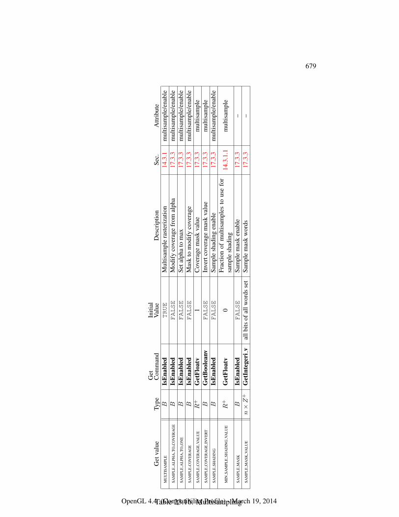
679
Get
valu
eTy
peG
etC
omm
and
Initi
alV
alue
Des
crip
tion
Sec.
Attr
ibut
eM
ULT
ISA
MPL
EB
IsE
nabl
edTRUE
Mul
tisam
ple
rast
eriz
atio
n14
.3.1
mul
tisam
ple/
enab
leSA
MPL
EA
LPH
ATO
CO
VE
RA
GE
BIs
Ena
bled
FALSE
Mod
ify
cove
rage
from
alph
a17
.3.3
mul
tisam
ple/
enab
leSA
MPL
EA
LPH
ATO
ON
EB
IsE
nabl
edFALSE
Seta
lpha
tom
ax17
.3.3
mul
tisam
ple/
enab
leSA
MPL
EC
OV
ER
AG
EB
IsE
nabl
edFALSE
Mas
kto
mod
ify
cove
rage
17.3
.3m
ultis
ampl
e/en
able
SAM
PLE
CO
VE
RA
GE
VAL
UE
R+
Get
Floa
tv1
Cov
erag
em
ask
valu
e17
.3.3
mul
tisam
ple
SAM
PLE
CO
VE
RA
GE
INV
ER
TB
Get
Boo
lean
vFALSE
Inve
rtco
vera
gem
ask
valu
e17
.3.3
mul
tisam
ple
SAM
PLE
SHA
DIN
GB
IsE
nabl
edFALSE
Sam
ple
shad
ing
enab
le17
.3.3
mul
tisam
ple/
enab
le
MIN
SAM
PLE
SHA
DIN
GVA
LU
ER
+G
etFl
oatv
0Fr
actio
nof
mul
tisam
ples
tous
efo
rsa
mpl
esh
adin
g14
.3.1
.1m
ultis
ampl
e
SAM
PLE
MA
SKB
IsE
nabl
edFALSE
Sam
ple
mas
ken
able
17.3
.3–
SAM
PLE
MA
SKVA
LU
En×Z
+G
etIn
tege
riv
allb
itsof
allw
ords
set
Sam
ple
mas
kw
ords
17.3
.3–
Table 23.16. MultisamplingOpenGL 4.4 (Compatibility Profile) - March 19, 2014
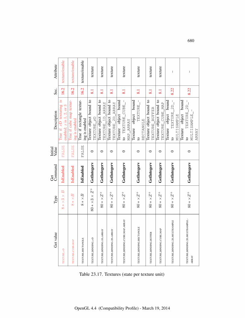
680
Get
valu
eTy
peG
etC
omm
and
Initi
alV
alue
Des
crip
tion
Sec.
Attr
ibut
e
TE
XT
UR
Ex
D8∗×
3×B
IsE
nabl
edFALSE
True
ifx
Dte
xtur
ing
isen
able
d;x
is1
,2,o
r316
.2te
xtur
e/en
able
TE
XT
UR
EC
UB
EM
AP
8∗×B
IsE
nabl
edFALSE
True
ifcu
bem
apte
xtur
-in
gis
enab
led
16.2
text
ure/
enab
le
TE
XT
UR
ER
EC
TAN
GL
E8∗×B
IsE
nabl
edFALSE
True
ifre
ctan
gle
text
ur-
ing
isen
able
d16
.2te
xtur
e/en
able
TE
XT
UR
EB
IND
ING
xD
80∗×
3×Z
+G
etIn
tege
rv0
Text
ure
obje
ctbo
und
toTEXTURE_xD
8.1
text
ure
TE
XT
UR
EB
IND
ING
1DA
RR
AY
80∗×Z
+G
etIn
tege
rv0
Text
ure
obje
ctbo
und
toTEXTURE_1D_ARRAY
8.1
text
ure
TE
XT
UR
EB
IND
ING
2DA
RR
AY
80∗×Z
+G
etIn
tege
rv0
Text
ure
obje
ctbo
und
toTEXTURE_2D_ARRAY
8.1
text
ure
TE
XT
UR
EB
IND
ING
CU
BE
MA
PA
RR
AY
80∗×Z
+G
etIn
tege
rv0
Text
ure
obje
ctbo
und
toTEXTURE_CUBE_-
MAP_ARRAY
8.1
text
ure
TE
XT
UR
EB
IND
ING
RE
CTA
NG
LE
80∗×Z
+G
etIn
tege
rv0
Text
ure
obje
ctbo
und
toTEXTURE_-
RECTANGLE
8.1
text
ure
TE
XT
UR
EB
IND
ING
BU
FFE
R80∗×Z
+G
etIn
tege
rv0
Text
ure
obje
ctbo
und
toTEXTURE_BUFFER
8.1
text
ure
TE
XT
UR
EB
IND
ING
CU
BE
MA
P80∗×Z
+G
etIn
tege
rv0
Text
ure
obje
ctbo
und
toTEXTURE_CUBE_MAP
8.1
text
ure
TE
XT
UR
EB
IND
ING
2DM
ULT
ISA
MPL
E80∗×Z
+G
etIn
tege
rv0
Text
ure
obje
ctbo
und
toTEXTURE_2D_-
MULTISAMPLE
8.22
–
TE
XT
UR
EB
IND
ING
2DM
ULT
ISA
MPL
E-
AR
RA
Y80∗×Z
+G
etIn
tege
rv0
Text
ure
obje
ctbo
und
toTEXTURE_2D_-
MULTISAMPLE_-
ARRAY
8.22
–
Table 23.17. Textures (state per texture unit)
OpenGL 4.4 (Compatibility Profile) - March 19, 2014
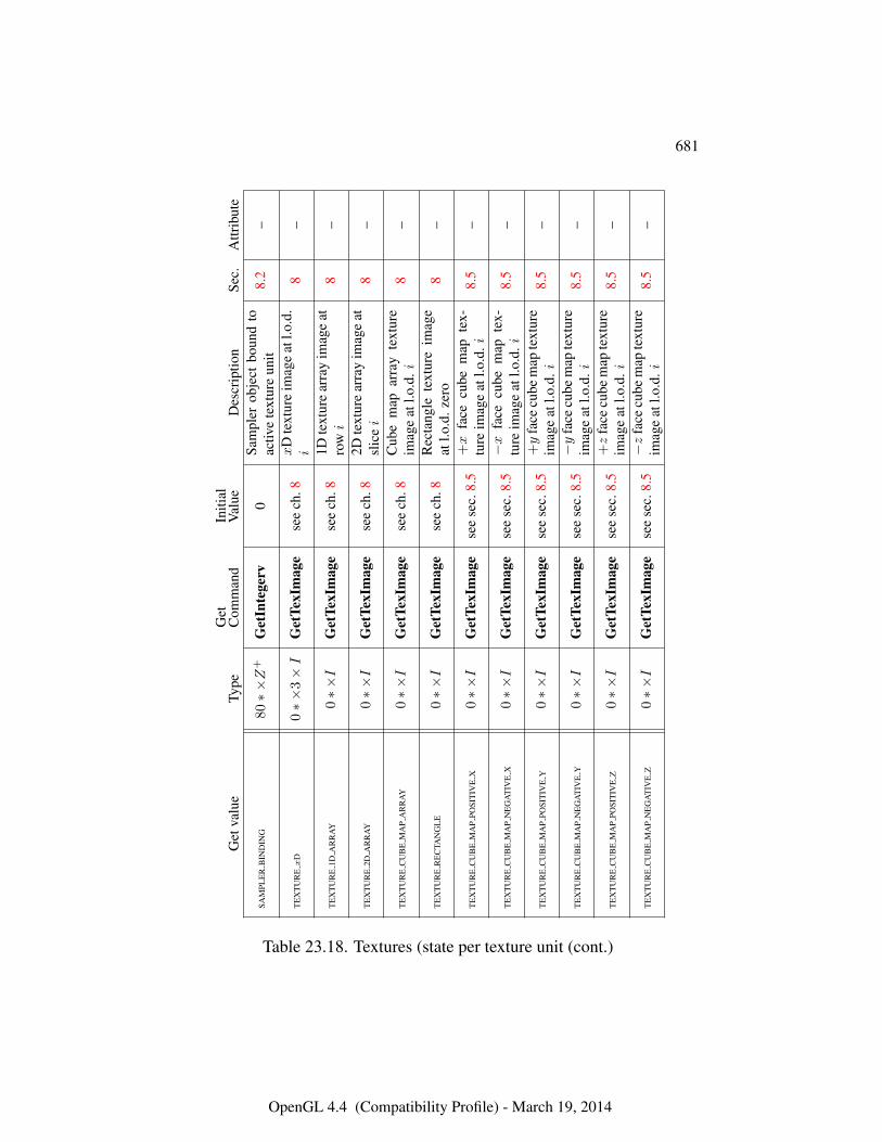
681
Get
valu
eTy
peG
etC
omm
and
Initi
alV
alue
Des
crip
tion
Sec.
Attr
ibut
e
SAM
PLE
RB
IND
ING
80∗×Z
+G
etIn
tege
rv0
Sam
pler
obje
ctbo
und
toac
tive
text
ure
unit
8.2
–
TE
XT
UR
Ex
D0∗×
3×I
Get
TexI
mag
ese
ech
.8x
Dte
xtur
eim
age
atl.o
.d.
i8
–
TE
XT
UR
E1D
AR
RA
Y0∗×I
Get
TexI
mag
ese
ech
.81D
text
ure
arra
yim
age
atro
wi
8–
TE
XT
UR
E2D
AR
RA
Y0∗×I
Get
TexI
mag
ese
ech
.82D
text
ure
arra
yim
age
atsl
icei
8–
TE
XT
UR
EC
UB
EM
AP
AR
RA
Y0∗×I
Get
TexI
mag
ese
ech
.8C
ube
map
arra
yte
xtur
eim
age
atl.o
.d.i
8–
TE
XT
UR
ER
EC
TAN
GL
E0∗×I
Get
TexI
mag
ese
ech
.8R
ecta
ngle
text
ure
imag
eat
l.o.d
.zer
o8
–
TE
XT
UR
EC
UB
EM
AP
POSI
TIV
EX
0∗×I
Get
TexI
mag
ese
ese
c.8.
5+x
face
cube
map
tex-
ture
imag
eat
l.o.d
.i8.
5–
TE
XT
UR
EC
UB
EM
AP
NE
GA
TIV
EX
0∗×I
Get
TexI
mag
ese
ese
c.8.
5−x
face
cube
map
tex-
ture
imag
eat
l.o.d
.i8.
5–
TE
XT
UR
EC
UB
EM
AP
POSI
TIV
EY
0∗×I
Get
TexI
mag
ese
ese
c.8.
5+y
face
cube
map
text
ure
imag
eat
l.o.d
.i8.
5–
TE
XT
UR
EC
UB
EM
AP
NE
GA
TIV
EY
0∗×I
Get
TexI
mag
ese
ese
c.8.
5−y
face
cube
map
text
ure
imag
eat
l.o.d
.i8.
5–
TE
XT
UR
EC
UB
EM
AP
POSI
TIV
EZ
0∗×I
Get
TexI
mag
ese
ese
c.8.
5+z
face
cube
map
text
ure
imag
eat
l.o.d
.i8.
5–
TE
XT
UR
EC
UB
EM
AP
NE
GA
TIV
EZ
0∗×I
Get
TexI
mag
ese
ese
c.8.
5−z
face
cube
map
text
ure
imag
eat
l.o.d
.i8.
5–
Table 23.18. Textures (state per texture unit (cont.)
OpenGL 4.4 (Compatibility Profile) - March 19, 2014
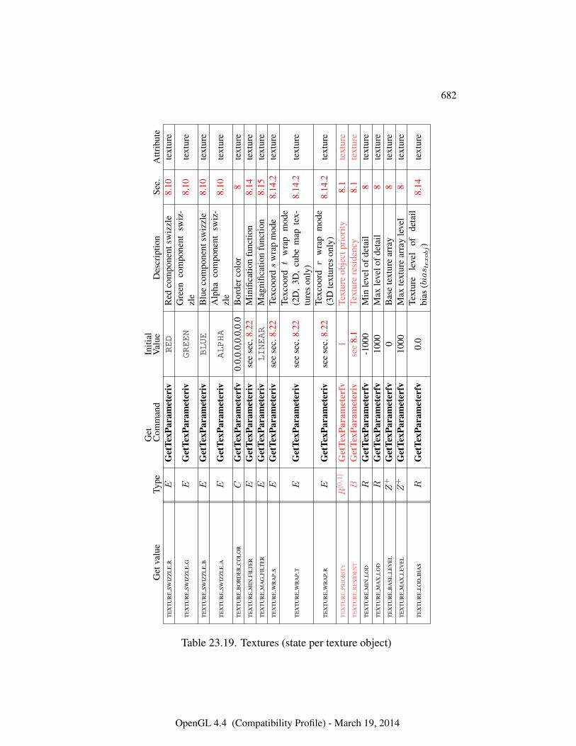
682
Get
valu
eTy
peG
etC
omm
and
Initi
alV
alue
Des
crip
tion
Sec.
Attr
ibut
eT
EX
TU
RE
SWIZ
ZL
ER
EG
etTe
xPar
amet
eriv
RED
Red
com
pone
ntsw
izzl
e8.
10te
xtur
e
TE
XT
UR
ESW
IZZ
LE
GE
Get
TexP
aram
eter
ivGREEN
Gre
enco
mpo
nent
swiz
-zl
e8.
10te
xtur
e
TE
XT
UR
ESW
IZZ
LE
BE
Get
TexP
aram
eter
ivBLUE
Blu
eco
mpo
nent
swiz
zle
8.10
text
ure
TE
XT
UR
ESW
IZZ
LE
AE
Get
TexP
aram
eter
ivALPHA
Alp
haco
mpo
nent
swiz
-zl
e8.
10te
xtur
e
TE
XT
UR
EB
OR
DE
RC
OL
OR
CG
etTe
xPar
amet
erfv
0.0,
0.0,
0.0,
0.0
Bor
derc
olor
8te
xtur
eT
EX
TU
RE
MIN
FILT
ER
EG
etTe
xPar
amet
eriv
see
sec.
8.22
Min
ifica
tion
func
tion
8.14
text
ure
TE
XT
UR
EM
AG
FILT
ER
EG
etTe
xPar
amet
eriv
LINEAR
Mag
nific
atio
nfu
nctio
n8.
15te
xtur
eT
EX
TU
RE
WR
AP
SE
Get
TexP
aram
eter
ivse
ese
c.8.
22Te
xcoo
rds
wra
pm
ode
8.14
.2te
xtur
e
TE
XT
UR
EW
RA
PT
EG
etTe
xPar
amet
eriv
see
sec.
8.22
Texc
oord
tw
rap
mod
e(2
D,
3D,
cube
map
tex-
ture
son
ly)
8.14
.2te
xtur
e
TE
XT
UR
EW
RA
PR
EG
etTe
xPar
amet
eriv
see
sec.
8.22
Texc
oord
rw
rap
mod
e(3
Dte
xtur
eson
ly)
8.14
.2te
xtur
e
TE
XT
UR
EPR
IOR
ITY
R[0,1]
Get
TexP
aram
eter
fv1
Text
ure
obje
ctpr
iori
ty8.
1te
xtur
eT
EX
TU
RE
RE
SID
EN
TB
Get
TexP
aram
eter
ivse
e8.
1Te
xtur
ere
side
ncy
8.1
text
ure
TE
XT
UR
EM
INL
OD
RG
etTe
xPar
amet
erfv
-100
0M
inle
velo
fdet
ail
8te
xtur
eT
EX
TU
RE
MA
XL
OD
RG
etTe
xPar
amet
erfv
1000
Max
leve
lofd
etai
l8
text
ure
TE
XT
UR
EB
ASE
LE
VE
LZ
+G
etTe
xPar
amet
erfv
0B
ase
text
ure
arra
y8
text
ure
TE
XT
UR
EM
AX
LE
VE
LZ
+G
etTe
xPar
amet
erfv
1000
Max
text
ure
arra
yle
vel
8te
xtur
e
TE
XT
UR
EL
OD
BIA
SR
Get
TexP
aram
eter
fv0.
0Te
xtur
ele
vel
ofde
tail
bias
(bias t
exobj)
8.14
text
ure
Table 23.19. Textures (state per texture object)
OpenGL 4.4 (Compatibility Profile) - March 19, 2014
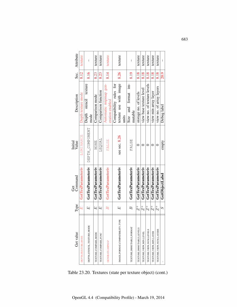
683
Get
valu
eTy
peG
etC
omm
and
Initi
alV
alue
Des
crip
tion
Sec.
Attr
ibut
eD
EPT
HT
EX
TU
RE
MO
DE
EG
etTe
xPar
amet
eriv
LUMINANCE
Dep
thte
xtur
em
ode
8.12
text
ure
DE
PTH
STE
NC
ILT
EX
TU
RE
MO
DE
EG
etTe
xPar
amet
eriv
DEPTH_COMPONENT
Dep
thst
enci
lte
xtur
em
ode
8.16
–
TE
XT
UR
EC
OM
PAR
EM
OD
EE
Get
TexP
aram
eter
ivNONE
Com
pari
son
mod
e8.
23te
xtur
eT
EX
TU
RE
CO
MPA
RE
FUN
CE
Get
TexP
aram
eter
ivLEQUAL
Com
pari
son
func
tion
8.23
text
ure
GE
NE
RA
TE
MIP
MA
PB
Get
TexP
aram
eter
ivFALSE
Aut
omat
icm
ipm
apge
n-er
atio
nen
able
d8.
14te
xtur
e
IMA
GE
FOR
MA
TC
OM
PAT
IBIL
ITY
TY
PEE
Get
TexP
aram
eter
ivse
ese
c.8.
26C
ompa
tibili
tyru
les
for
text
ure
use
with
imag
eun
its8.
26te
xtur
e
TE
XT
UR
EIM
MU
TAB
LE
FOR
MA
TB
Get
TexP
aram
eter
ivFALSE
Size
and
form
atim
-m
utab
le8.
19–
TE
XT
UR
EIM
MU
TAB
LE
LE
VE
LS
Z+
Get
TexP
aram
eter
iv0
stor
age
no.o
flev
els
8.18
text
ure
TE
XT
UR
EV
IEW
MIN
LE
VE
LZ
+G
etTe
xPar
amet
eriv
0vi
ewba
sete
xtur
ele
vel
8.18
text
ure
TE
XT
UR
EV
IEW
NU
ML
EV
EL
SZ
+G
etTe
xPar
amet
eriv
0vi
ewno
.oft
extu
rele
vels
8.18
text
ure
TE
XT
UR
EV
IEW
MIN
LA
YE
RZ
+G
etTe
xPar
amet
eriv
0vi
ewm
inar
ray
laye
r8.
18te
xtur
eT
EX
TU
RE
VIE
WN
UM
LA
YE
RS
Z+
Get
TexP
aram
eter
iv0
view
no.o
farr
ayla
yers
8.18
text
ure
–S
Get
Obj
ectL
abel
empt
yD
ebug
labe
l20
.9–
Table 23.20. Textures (state per texture object) (cont.)
OpenGL 4.4 (Compatibility Profile) - March 19, 2014
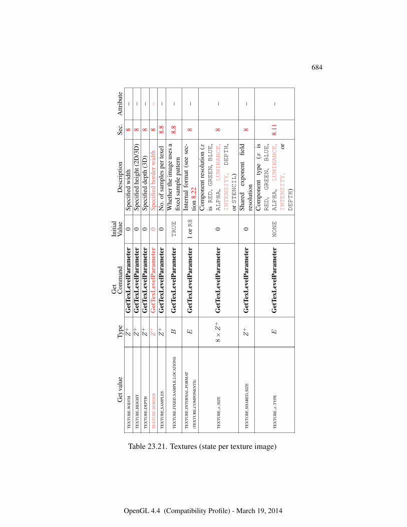
684
Get
valu
eTy
peG
etC
omm
and
Initi
alV
alue
Des
crip
tion
Sec.
Attr
ibut
eT
EX
TU
RE
WID
TH
Z+
Get
TexL
evel
Para
met
er0
Spec
ified
wid
th8
–T
EX
TU
RE
HE
IGH
TZ
+G
etTe
xLev
elPa
ram
eter
0Sp
ecifi
edhe
ight
(2D
/3D
)8
–T
EX
TU
RE
DE
PTH
Z+
Get
TexL
evel
Para
met
er0
Spec
ified
dept
h(3
D)
8–
TE
XT
UR
EB
OR
DE
RZ
+G
etTe
xLev
elPa
ram
eter
0Sp
ecifi
edbo
rder
wid
th8
–T
EX
TU
RE
SAM
PLE
SZ
+G
etTe
xLev
elPa
ram
eter
0N
o.of
sam
ples
pert
exel
8.8
–
TE
XT
UR
EFI
XE
DSA
MPL
EL
OC
AT
ION
SB
Get
TexL
evel
Para
met
erTRUE
Whe
ther
the
imag
eus
esa
fixed
sam
ple
patte
rn8.
8–
TE
XT
UR
EIN
TE
RN
AL
FOR
MA
T
(TE
XT
UR
EC
OM
PON
EN
TS)
EG
etTe
xLev
elPa
ram
eter
1orR8
Inte
rnal
form
at(s
eese
c-tio
n8.
228
–
TE
XT
UR
Ex
SIZ
E8×Z
+G
etTe
xLev
elPa
ram
eter
0
Com
pone
ntre
solu
tion
(xisRED
,GREEN
,BLUE
,ALPHA
,LUMINANCE
,INTENSITY
,DEPTH
,orSTENCIL
)
8–
TE
XT
UR
ESH
AR
ED
SIZ
EZ
+G
etTe
xLev
elPa
ram
eter
0Sh
ared
expo
nent
field
reso
lutio
n8
–
TE
XT
UR
Ex
TY
PEE
Get
TexL
evel
Para
met
erNONE
Com
pone
ntty
pe(x
isRED
,GREEN
,BLUE
,ALPHA
,LUMINANCE
,INTENSITY
,or
DEPTH
)
8.11
–
Table 23.21. Textures (state per texture image)
OpenGL 4.4 (Compatibility Profile) - March 19, 2014
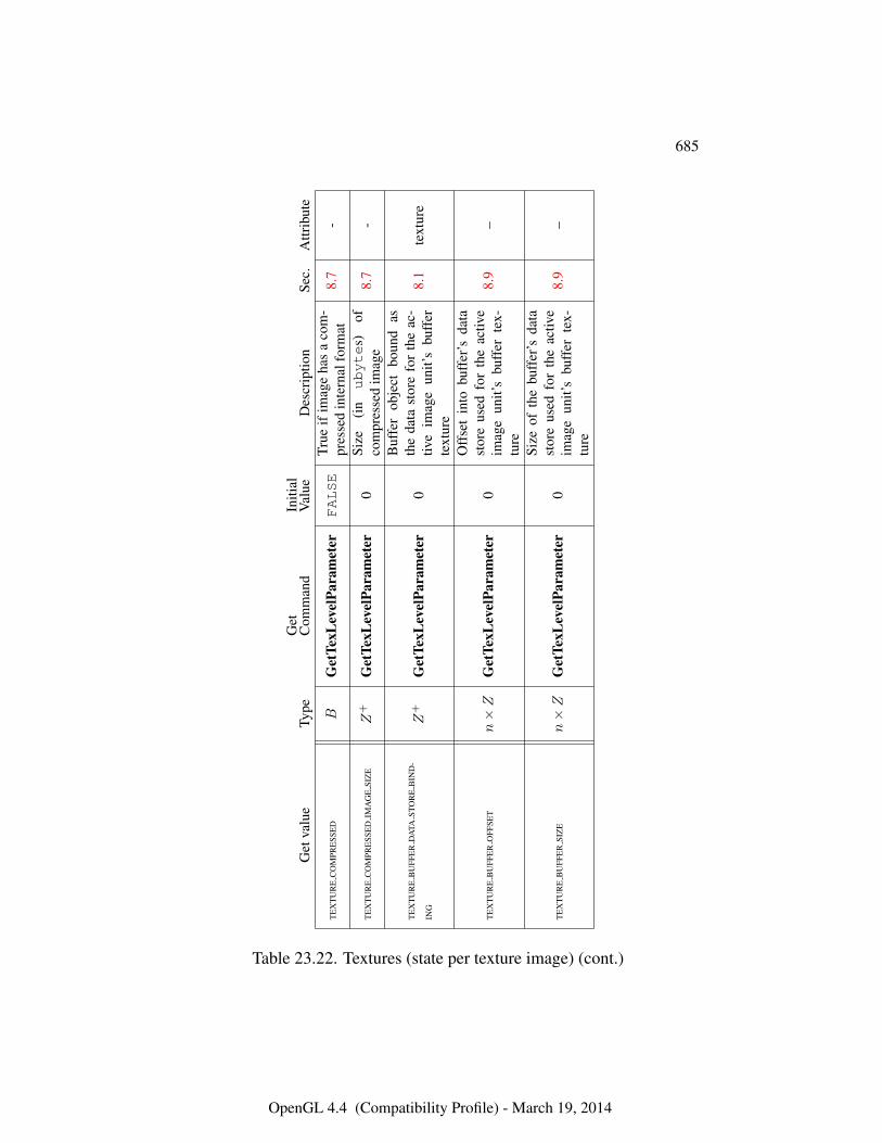
685
Get
valu
eTy
peG
etC
omm
and
Initi
alV
alue
Des
crip
tion
Sec.
Attr
ibut
e
TE
XT
UR
EC
OM
PRE
SSE
DB
Get
TexL
evel
Para
met
erFALSE
True
ifim
age
has
aco
m-
pres
sed
inte
rnal
form
at8.
7-
TE
XT
UR
EC
OM
PRE
SSE
DIM
AG
ESI
ZE
Z+
Get
TexL
evel
Para
met
er0
Size
(in
ubyte
s)of
com
pres
sed
imag
e8.
7-
TE
XT
UR
EB
UFF
ER
DA
TAST
OR
EB
IND
-
ING
Z+
Get
TexL
evel
Para
met
er0
Buf
fer
obje
ctbo
und
asth
eda
tast
ore
for
the
ac-
tive
imag
eun
it’s
buff
erte
xtur
e
8.1
text
ure
TE
XT
UR
EB
UFF
ER
OFF
SET
n×Z
Get
TexL
evel
Para
met
er0
Off
set
into
buff
er’s
data
stor
eus
edfo
rth
eac
tive
imag
eun
it’s
buff
erte
x-tu
re
8.9
–
TE
XT
UR
EB
UFF
ER
SIZ
En×Z
Get
TexL
evel
Para
met
er0
Size
ofth
ebu
ffer
’sda
tast
ore
used
for
the
activ
eim
age
unit’
sbu
ffer
tex-
ture
8.9
–
Table 23.22. Textures (state per texture image) (cont.)
OpenGL 4.4 (Compatibility Profile) - March 19, 2014
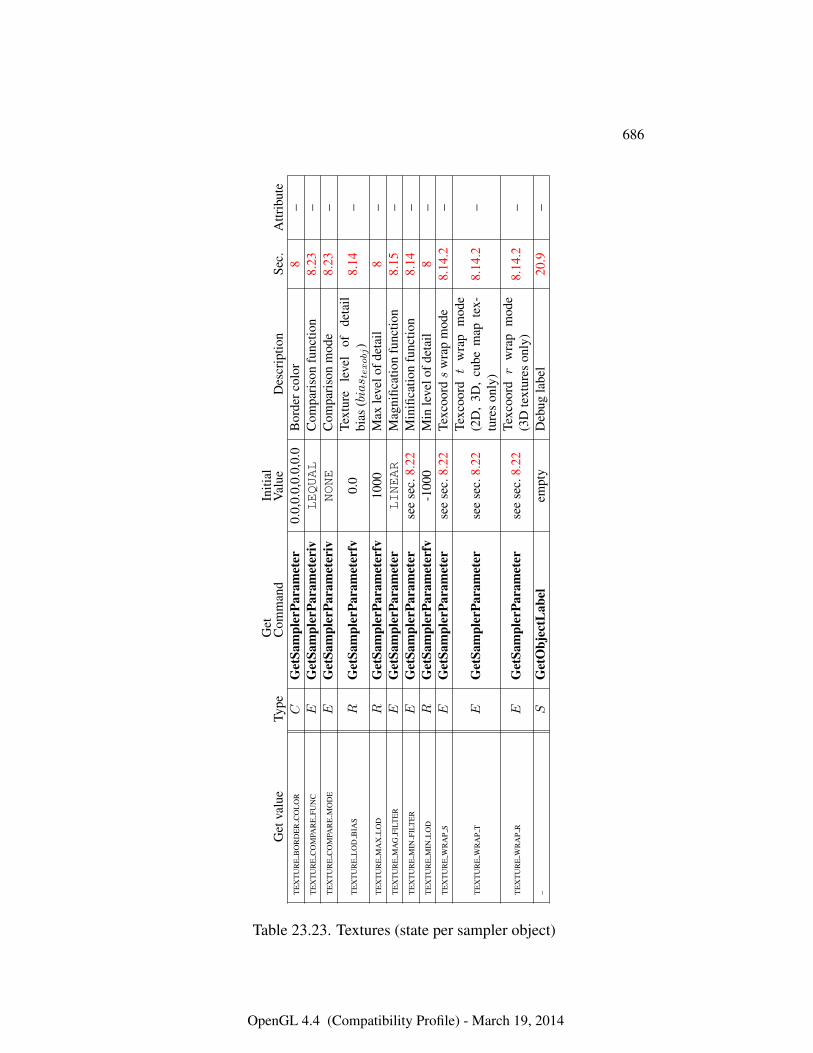
686
Get
valu
eTy
peG
etC
omm
and
Initi
alV
alue
Des
crip
tion
Sec.
Attr
ibut
eT
EX
TU
RE
BO
RD
ER
CO
LO
RC
Get
Sam
pler
Para
met
er0.
0,0.
0,0.
0,0.
0B
orde
rcol
or8
–T
EX
TU
RE
CO
MPA
RE
FUN
CE
Get
Sam
pler
Para
met
eriv
LEQUAL
Com
pari
son
func
tion
8.23
–T
EX
TU
RE
CO
MPA
RE
MO
DE
EG
etSa
mpl
erPa
ram
eter
ivNONE
Com
pari
son
mod
e8.
23–
TE
XT
UR
EL
OD
BIA
SR
Get
Sam
pler
Para
met
erfv
0.0
Text
ure
leve
lof
deta
ilbi
as(bias t
exobj)
8.14
–
TE
XT
UR
EM
AX
LO
DR
Get
Sam
pler
Para
met
erfv
1000
Max
leve
lofd
etai
l8
–T
EX
TU
RE
MA
GFI
LTE
RE
Get
Sam
pler
Para
met
erLINEAR
Mag
nific
atio
nfu
nctio
n8.
15–
TE
XT
UR
EM
INFI
LTE
RE
Get
Sam
pler
Para
met
erse
ese
c.8.
22M
inifi
catio
nfu
nctio
n8.
14–
TE
XT
UR
EM
INL
OD
RG
etSa
mpl
erPa
ram
eter
fv-1
000
Min
leve
lofd
etai
l8
–T
EX
TU
RE
WR
AP
SE
Get
Sam
pler
Para
met
erse
ese
c.8.
22Te
xcoo
rds
wra
pm
ode
8.14
.2–
TE
XT
UR
EW
RA
PT
EG
etSa
mpl
erPa
ram
eter
see
sec.
8.22
Texc
oord
tw
rap
mod
e(2
D,
3D,
cube
map
tex-
ture
son
ly)
8.14
.2–
TE
XT
UR
EW
RA
PR
EG
etSa
mpl
erPa
ram
eter
see
sec.
8.22
Texc
oord
rw
rap
mod
e(3
Dte
xtur
eson
ly)
8.14
.2–
–S
Get
Obj
ectL
abel
empt
yD
ebug
labe
l20
.9–
Table 23.23. Textures (state per sampler object)
OpenGL 4.4 (Compatibility Profile) - March 19, 2014
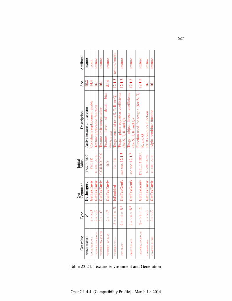
687
Get
valu
eTy
peG
etC
omm
and
Initi
alV
alue
Des
crip
tion
Sec.
Attr
ibut
eA
CT
IVE
TE
XT
UR
EE
Get
Inte
gerv
TEXTURE0
Act
ive
text
ure
unit
sele
ctor
10.2
text
ure
CO
OR
DR
EPL
AC
E2∗×B
Get
TexE
nviv
FALSE
Coo
rdin
ate
repl
acem
ente
nabl
e14
.4po
int
TE
XT
UR
EE
NV
MO
DE
2∗×E
Get
TexE
nviv
MODULATE
Text
ure
appl
icat
ion
func
tion
16.1
text
ure
TE
XT
UR
EE
NV
CO
LO
R2∗×C
Get
TexE
nvfv
0.0,
0.0,
0.0,
0.0
Text
ure
envi
ronm
entc
olor
16.1
text
ure
TE
XT
UR
EL
OD
BIA
S2∗×R
Get
TexE
nvfv
0.0
Text
ure
leve
lof
deta
ilbi
asbias t
exunit
8.14
text
ure
TE
XT
UR
EG
EN
x2∗×
4×B
IsE
nabl
edFALSE
Texg
enen
able
d(x
isS,
T,R
,orQ
)12
.1.3
text
ure/
enab
le
EY
EPL
AN
E2∗×
4×R
4G
etTe
xGen
fvse
ese
c.12
.1.3
Texg
enpl
ane
equa
tion
coef
ficie
nts
(for
S,T,
R,a
ndQ
)12
.1.3
text
ure
OB
JEC
TPL
AN
E2∗×
4×R
4G
etTe
xGen
fvse
ese
c.12
.1.3
Texg
enob
ject
linea
rco
effic
ient
s(f
orS,
T,R
,and
Q)
12.1
.3te
xtur
e
TE
XT
UR
EG
EN
MO
DE
2∗×
4×E
Get
TexG
eniv
EYE_LINEAR
Func
tion
used
for
texg
en(f
orS,
T,R
,and
Q12
.1.3
text
ure
CO
MB
INE
RG
B2∗×E
Get
TexE
nviv
MODULATE
RG
Bco
mbi
nerf
unct
ion
16.1
text
ure
CO
MB
INE
AL
PHA
2∗×E
Get
TexE
nviv
MODULATE
Alp
haco
mbi
nerf
unct
ion
16.1
text
ure
Table 23.24. Texture Environment and Generation
OpenGL 4.4 (Compatibility Profile) - March 19, 2014
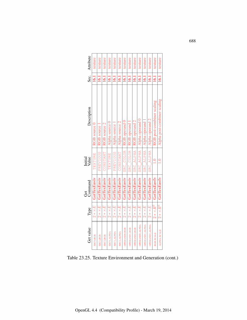
688
Get
valu
eTy
peG
etC
omm
and
Initi
alV
alue
Des
crip
tion
Sec.
Attr
ibut
eSR
C0
RG
B2∗×E
Get
TexE
nviv
TEXTURE
RG
Bso
urce
016
.1te
xtur
eSR
C1
RG
B2∗×E
Get
TexE
nviv
PREVIOUS
RG
Bso
urce
116
.1te
xtur
eSR
C2
RG
B2∗×E
Get
TexE
nviv
CONSTANT
RG
Bso
urce
216
.1te
xtur
eSR
C0
AL
PHA
2∗×E
Get
TexE
nviv
TEXTURE
Alp
haso
urce
016
.1te
xtur
eSR
C1
AL
PHA
2∗×E
Get
TexE
nviv
PREVIOUS
Alp
haso
urce
116
.1te
xtur
eSR
C2
AL
PHA
2∗×E
Get
TexE
nviv
CONSTANT
Alp
haso
urce
216
.1te
xtur
eO
PER
AN
D0
RG
B2∗×E
Get
TexE
nviv
SRC_COLOR
RG
Bop
eran
d0
16.1
text
ure
OPE
RA
ND
1R
GB
2∗×E
Get
TexE
nviv
SRC_COLOR
RG
Bop
eran
d1
16.1
text
ure
OPE
RA
ND
2R
GB
2∗×E
Get
TexE
nviv
SRC_ALPHA
RG
Bop
eran
d2
16.1
text
ure
OPE
RA
ND
0A
LPH
A2∗×E
Get
TexE
nviv
SRC_ALPHA
Alp
haop
eran
d0
16.1
text
ure
OPE
RA
ND
1A
LPH
A2∗×E
Get
TexE
nviv
SRC_ALPHA
Alp
haop
eran
d1
16.1
text
ure
OPE
RA
ND
2A
LPH
A2∗×E
Get
TexE
nviv
SRC_ALPHA
Alp
haop
eran
d2
16.1
text
ure
RG
BSC
AL
E2∗×R
3G
etTe
xEnv
fv1.
0R
GB
post
-com
bine
rsca
ling
16.1
text
ure
AL
PHA
SCA
LE
2∗×R
3G
etTe
xEnv
fv1.
0A
lpha
post
-com
bine
rsca
ling
16.1
text
ure
Table 23.25. Texture Environment and Generation (cont.)
OpenGL 4.4 (Compatibility Profile) - March 19, 2014
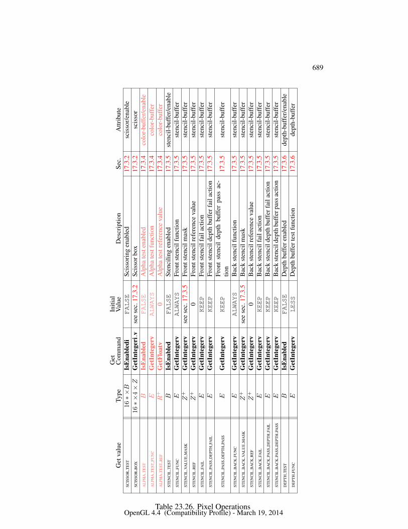
689
Get
valu
eTy
peG
etC
omm
and
Initi
alV
alue
Des
crip
tion
Sec.
Attr
ibut
eSC
ISSO
RT
EST
16∗×B
IsE
nabl
edi
FALSE
Scis
sori
ngen
able
d17
.3.2
scis
sor/
enab
leSC
ISSO
RB
OX
16∗×
4×Z
Get
Inte
geri
vse
ese
c.17
.3.2
Scis
sorb
ox17
.3.2
scis
sor
AL
PHA
TE
STB
IsE
nabl
edFALSE
Alp
hate
sten
able
d17
.3.4
colo
r-bu
ffer
/ena
ble
AL
PHA
TE
STFU
NC
EG
etIn
tege
rvALWAYS
Alp
hate
stfu
nctio
n17
.3.4
colo
r-bu
ffer
AL
PHA
TE
STR
EF
R+
Get
Floa
tv0
Alp
hate
stre
fere
nce
valu
e17
.3.4
colo
r-bu
ffer
STE
NC
ILT
EST
BIs
Ena
bled
FALSE
Sten
cilin
gen
able
d17
.3.5
sten
cil-
buff
er/e
nabl
eST
EN
CIL
FUN
CE
Get
Inte
gerv
ALWAYS
Fron
tste
ncil
func
tion
17.3
.5st
enci
l-bu
ffer
STE
NC
ILVA
LU
EM
ASK
Z+
Get
Inte
gerv
see
sec.
17.3
.5Fr
onts
tenc
ilm
ask
17.3
.5st
enci
l-bu
ffer
STE
NC
ILR
EF
Z+
Get
Inte
gerv
0Fr
onts
tenc
ilre
fere
nce
valu
e17
.3.5
sten
cil-
buff
erST
EN
CIL
FAIL
EG
etIn
tege
rvKEEP
Fron
tste
ncil
fail
actio
n17
.3.5
sten
cil-
buff
erST
EN
CIL
PASS
DE
PTH
FAIL
EG
etIn
tege
rvKEEP
Fron
tste
ncil
dept
hbu
ffer
fail
actio
n17
.3.5
sten
cil-
buff
er
STE
NC
ILPA
SSD
EPT
HPA
SSE
Get
Inte
gerv
KEEP
Fron
tst
enci
lde
pth
buff
erpa
ssac
-tio
n17
.3.5
sten
cil-
buff
er
STE
NC
ILB
AC
KFU
NC
EG
etIn
tege
rvALWAYS
Bac
kst
enci
lfun
ctio
n17
.3.5
sten
cil-
buff
erST
EN
CIL
BA
CK
VAL
UE
MA
SKZ
+G
etIn
tege
rvse
ese
c.17
.3.5
Bac
kst
enci
lmas
k17
.3.5
sten
cil-
buff
erST
EN
CIL
BA
CK
RE
FZ
+G
etIn
tege
rv0
Bac
kst
enci
lref
eren
ceva
lue
17.3
.5st
enci
l-bu
ffer
STE
NC
ILB
AC
KFA
ILE
Get
Inte
gerv
KEEP
Bac
kst
enci
lfai
lact
ion
17.3
.5st
enci
l-bu
ffer
STE
NC
ILB
AC
KPA
SSD
EPT
HFA
ILE
Get
Inte
gerv
KEEP
Bac
kst
enci
ldep
thbu
ffer
fail
actio
n17
.3.5
sten
cil-
buff
erST
EN
CIL
BA
CK
PASS
DE
PTH
PASS
EG
etIn
tege
rvKEEP
Bac
kst
enci
ldep
thbu
ffer
pass
actio
n17
.3.5
sten
cil-
buff
erD
EPT
HT
EST
BIs
Ena
bled
FALSE
Dep
thbu
ffer
enab
led
17.3
.6de
pth-
buff
er/e
nabl
eD
EPT
HFU
NC
EG
etIn
tege
rvLESS
Dep
thbu
ffer
test
func
tion
17.3
.6de
pth-
buff
er
Table 23.26. Pixel OperationsOpenGL 4.4 (Compatibility Profile) - March 19, 2014
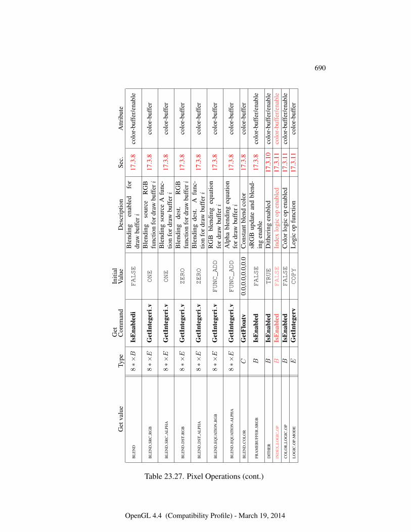
690
Get
valu
eTy
peG
etC
omm
and
Initi
alV
alue
Des
crip
tion
Sec.
Attr
ibut
e
BL
EN
D8∗×B
IsE
nabl
edi
FALSE
Ble
ndin
gen
able
dfo
rdr
awbu
fferi
17.3
.8co
lor-
buff
er/e
nabl
e
BL
EN
DSR
CR
GB
8∗×E
Get
Inte
geri
vONE
Ble
ndin
gso
urce
RG
Bfu
nctio
nfo
rdra
wbu
fferi
17.3
.8co
lor-
buff
er
BL
EN
DSR
CA
LPH
A8∗×E
Get
Inte
geri
vONE
Ble
ndin
gso
urce
Afu
nc-
tion
ford
raw
buff
eri
17.3
.8co
lor-
buff
er
BL
EN
DD
STR
GB
8∗×E
Get
Inte
geri
vZERO
Ble
ndin
gde
st.
RG
Bfu
nctio
nfo
rdra
wbu
fferi
17.3
.8co
lor-
buff
er
BL
EN
DD
STA
LPH
A8∗×E
Get
Inte
geri
vZERO
Ble
ndin
gde
st.
Afu
nc-
tion
ford
raw
buff
eri
17.3
.8co
lor-
buff
er
BL
EN
DE
QU
AT
ION
RG
B8∗×E
Get
Inte
geri
vFUNC_ADD
RG
Bbl
endi
ngeq
uatio
nfo
rdra
wbu
fferi
17.3
.8co
lor-
buff
er
BL
EN
DE
QU
AT
ION
AL
PHA
8∗×E
Get
Inte
geri
vFUNC_ADD
Alp
habl
endi
ngeq
uatio
nfo
rdra
wbu
fferi
17.3
.8co
lor-
buff
er
BL
EN
DC
OL
OR
CG
etFl
oatv
0.0,
0.0,
0.0,
0.0
Con
stan
tble
ndco
lor
17.3
.8co
lor-
buff
er
FRA
ME
BU
FFE
RSR
GB
BIs
Ena
bled
FALSE
sRG
Bup
date
and
blen
d-in
gen
able
17.3
.8co
lor-
buff
er/e
nabl
e
DIT
HE
RB
IsE
nabl
edTRUE
Dith
erin
gen
able
d17
.3.1
0co
lor-
buff
er/e
nabl
eIN
DE
XL
OG
ICO
PB
IsE
nabl
edFALSE
Inde
xlo
gic
open
able
d17
.3.1
1co
lor-
buff
er/e
nabl
eC
OL
OR
LO
GIC
OP
BIs
Ena
bled
FALSE
Col
orlo
gic
open
able
d17
.3.1
1co
lor-
buff
er/e
nabl
eL
OG
ICO
PM
OD
EE
Get
Inte
gerv
COPY
Log
icop
func
tion
17.3
.11
colo
r-bu
ffer
Table 23.27. Pixel Operations (cont.)
OpenGL 4.4 (Compatibility Profile) - March 19, 2014
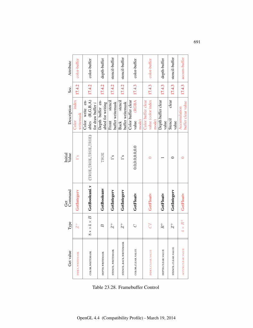
691
Get
valu
eTy
peG
etC
omm
and
Initi
alV
alue
Des
crip
tion
Sec.
Attr
ibut
e
IND
EX
WR
ITE
MA
SKZ
+G
etIn
tege
rv1’
sC
olor
inde
xw
rite
mas
k17
.4.2
colo
r-bu
ffer
CO
LO
RW
RIT
EM
ASK
8∗×
4×B
Get
Boo
lean
iv(TRUE
,TRUE
,TRUE
,TRUE
)C
olor
wri
teen
-ab
les
(R,G
,B,A
)fo
rdra
wbu
fferi
17.4
.2co
lor-
buff
er
DE
PTH
WR
ITE
MA
SKB
Get
Boo
lean
vTRUE
Dep
thbu
ffer
en-
able
dfo
rwri
ting
17.4
.2de
pth-
buff
er
STE
NC
ILW
RIT
EM
ASK
Z+
Get
Inte
gerv
1’s
Fron
tst
enci
lbu
ffer
wri
tem
ask
17.4
.2st
enci
l-bu
ffer
STE
NC
ILB
AC
KW
RIT
EM
ASK
Z+
Get
Inte
gerv
1’s
Bac
kst
enci
lbu
ffer
wri
tem
ask
17.4
.2st
enci
l-bu
ffer
CO
LO
RC
LE
AR
VAL
UE
CG
etFl
oatv
0.0,
0.0,
0.0,
0.0
Col
orbu
ffer
clea
rva
lue
(RG
BA
mod
e)17
.4.3
colo
r-bu
ffer
IND
EX
CL
EA
RVA
LU
ECI
Get
Floa
tv0
Col
orbu
ffer
clea
rva
lue
(col
orin
dex
mod
e)17
.4.3
colo
r-bu
ffer
DE
PTH
CL
EA
RVA
LU
ER
+G
etFl
oatv
1D
epth
buff
ercl
ear
valu
e17
.4.3
dept
h-bu
ffer
STE
NC
ILC
LE
AR
VAL
UE
Z+
Get
Inte
gerv
0St
enci
lcl
ear
valu
e17
.4.3
sten
cil-
buff
er
AC
CU
MC
LE
AR
VAL
UE
4×R
+G
etFl
oatv
0A
ccum
ulat
ion
buff
ercl
earv
alue
17.4
.3ac
cum
-buf
fer
Table 23.28. Framebuffer Control
OpenGL 4.4 (Compatibility Profile) - March 19, 2014
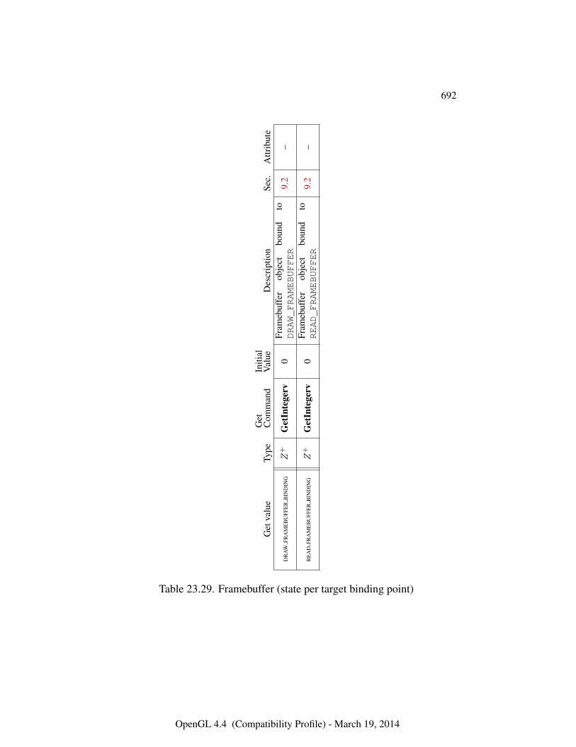
692
Get
valu
eTy
peG
etC
omm
and
Initi
alV
alue
Des
crip
tion
Sec.
Attr
ibut
e
DR
AW
FRA
ME
BU
FFE
RB
IND
ING
Z+
Get
Inte
gerv
0Fr
ameb
uffe
rob
ject
boun
dto
DRAW_FRAMEBUFFER
9.2
–
RE
AD
FRA
ME
BU
FFE
RB
IND
ING
Z+
Get
Inte
gerv
0Fr
ameb
uffe
rob
ject
boun
dto
READ_FRAMEBUFFER
9.2
–
Table 23.29. Framebuffer (state per target binding point)
OpenGL 4.4 (Compatibility Profile) - March 19, 2014
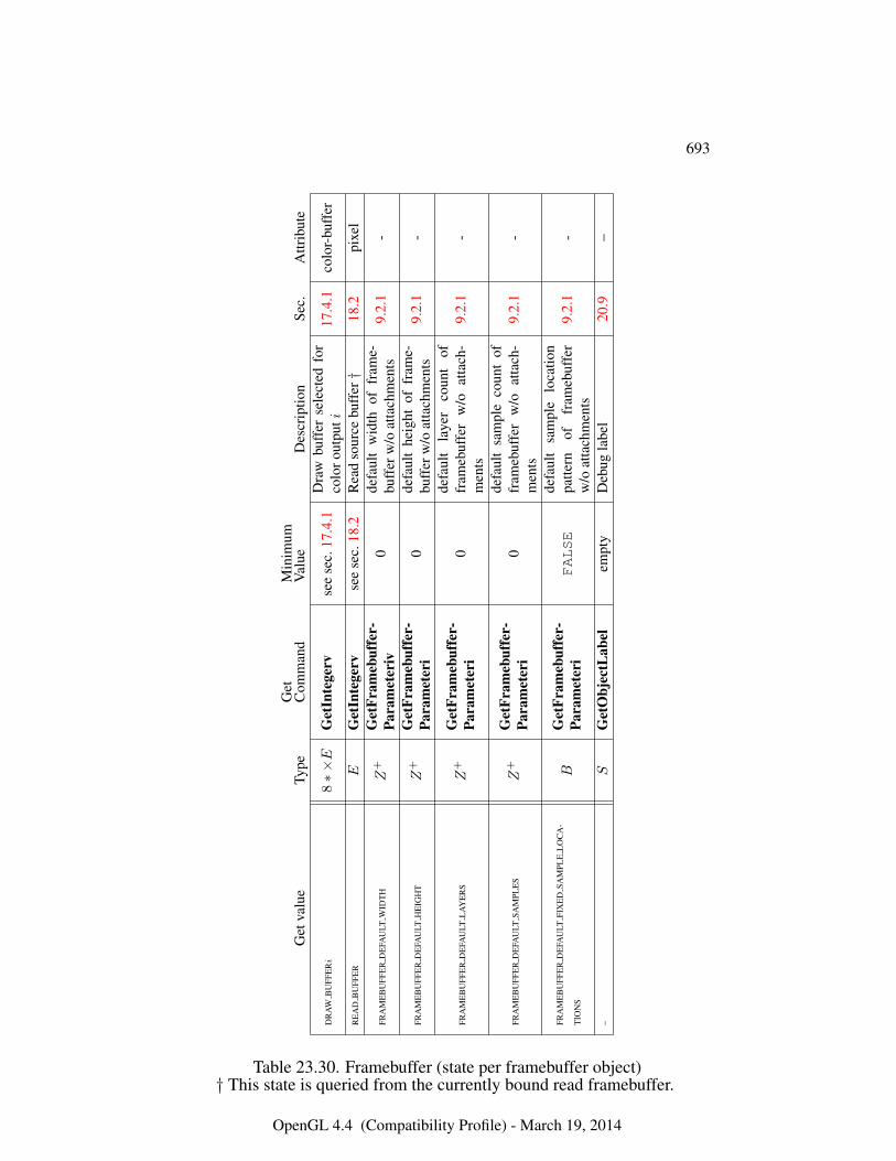
693
Get
valu
eTy
peG
etC
omm
and
Min
imum
Val
ueD
escr
iptio
nSe
c.A
ttrib
ute
DR
AW
BU
FFE
Ri
8∗×E
Get
Inte
gerv
see
sec.
17.4
.1D
raw
buff
erse
lect
edfo
rco
loro
utpu
ti17
.4.1
colo
r-bu
ffer
RE
AD
BU
FFE
RE
Get
Inte
gerv
see
sec.
18.2
Rea
dso
urce
buff
er†
18.2
pixe
l
FRA
ME
BU
FFE
RD
EFA
ULT
WID
TH
Z+
Get
Fram
ebuf
fer-
Para
met
eriv
0de
faul
tw
idth
offr
ame-
buff
erw
/oat
tach
men
ts9.
2.1
-
FRA
ME
BU
FFE
RD
EFA
ULT
HE
IGH
TZ
+G
etFr
ameb
uffe
r-Pa
ram
eter
i0
defa
ult
heig
htof
fram
e-bu
ffer
w/o
atta
chm
ents
9.2.
1-
FRA
ME
BU
FFE
RD
EFA
ULT
LA
YE
RS
Z+
Get
Fram
ebuf
fer-
Para
met
eri
0de
faul
tla
yer
coun
tof
fram
ebuf
fer
w/o
atta
ch-
men
ts9.
2.1
-
FRA
ME
BU
FFE
RD
EFA
ULT
SAM
PLE
SZ
+G
etFr
ameb
uffe
r-Pa
ram
eter
i0
defa
ult
sam
ple
coun
tof
fram
ebuf
fer
w/o
atta
ch-
men
ts9.
2.1
-
FRA
ME
BU
FFE
RD
EFA
ULT
FIX
ED
SAM
PLE
LO
CA
-
TIO
NS
BG
etFr
ameb
uffe
r-Pa
ram
eter
iFALSE
defa
ult
sam
ple
loca
tion
patte
rnof
fram
ebuf
fer
w/o
atta
chm
ents
9.2.
1-
–S
Get
Obj
ectL
abel
empt
yD
ebug
labe
l20
.9–
Table 23.30. Framebuffer (state per framebuffer object)† This state is queried from the currently bound read framebuffer.
OpenGL 4.4 (Compatibility Profile) - March 19, 2014
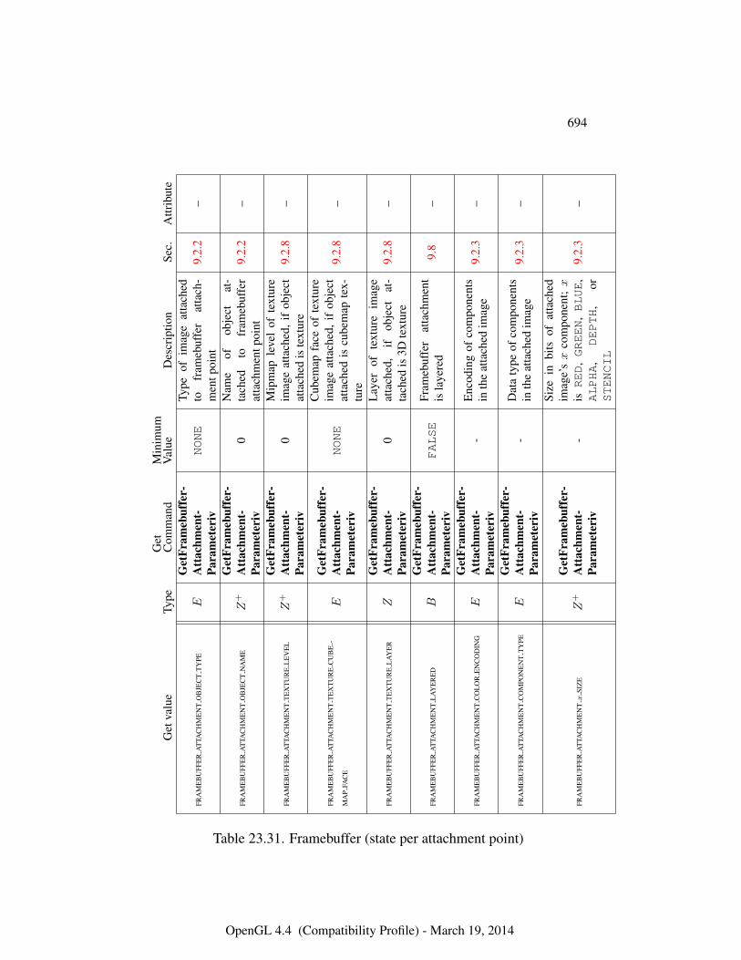
694
Get
valu
eTy
peG
etC
omm
and
Min
imum
Val
ueD
escr
iptio
nSe
c.A
ttrib
ute
FRA
ME
BU
FFE
RA
TTA
CH
ME
NT
OB
JEC
TT
YPE
EG
etFr
ameb
uffe
r-A
ttac
hmen
t-Pa
ram
eter
ivNONE
Type
ofim
age
atta
ched
tofr
ameb
uffe
rat
tach
-m
entp
oint
9.2.
2–
FRA
ME
BU
FFE
RA
TTA
CH
ME
NT
OB
JEC
TN
AM
EZ
+G
etFr
ameb
uffe
r-A
ttac
hmen
t-Pa
ram
eter
iv0
Nam
eof
obje
ctat
-ta
ched
tofr
ameb
uffe
rat
tach
men
tpoi
nt9.
2.2
–
FRA
ME
BU
FFE
RA
TTA
CH
ME
NT
TE
XT
UR
EL
EV
EL
Z+
Get
Fram
ebuf
fer-
Att
achm
ent-
Para
met
eriv
0M
ipm
aple
vel
ofte
xtur
eim
age
atta
ched
,if
obje
ctat
tach
edis
text
ure
9.2.
8–
FRA
ME
BU
FFE
RA
TTA
CH
ME
NT
TE
XT
UR
EC
UB
E-
MA
PFA
CE
EG
etFr
ameb
uffe
r-A
ttac
hmen
t-Pa
ram
eter
ivNONE
Cub
emap
face
ofte
xtur
eim
age
atta
ched
,if
obje
ctat
tach
edis
cube
map
tex-
ture
9.2.
8–
FRA
ME
BU
FFE
RA
TTA
CH
ME
NT
TE
XT
UR
EL
AY
ER
ZG
etFr
ameb
uffe
r-A
ttac
hmen
t-Pa
ram
eter
iv0
Lay
erof
text
ure
imag
eat
tach
ed,
ifob
ject
at-
tach
edis
3Dte
xtur
e9.
2.8
–
FRA
ME
BU
FFE
RA
TTA
CH
ME
NT
LA
YE
RE
DB
Get
Fram
ebuf
fer-
Att
achm
ent-
Para
met
eriv
FALSE
Fram
ebuf
fer
atta
chm
ent
isla
yere
d9.
8–
FRA
ME
BU
FFE
RA
TTA
CH
ME
NT
CO
LO
RE
NC
OD
ING
EG
etFr
ameb
uffe
r-A
ttac
hmen
t-Pa
ram
eter
iv-
Enc
odin
gof
com
pone
nts
inth
eat
tach
edim
age
9.2.
3–
FRA
ME
BU
FFE
RA
TTA
CH
ME
NT
CO
MPO
NE
NT
TY
PEE
Get
Fram
ebuf
fer-
Att
achm
ent-
Para
met
eriv
-D
ata
type
ofco
mpo
nent
sin
the
atta
ched
imag
e9.
2.3
–
FRA
ME
BU
FFE
RA
TTA
CH
ME
NTx
SIZ
EZ
+G
etFr
ameb
uffe
r-A
ttac
hmen
t-Pa
ram
eter
iv-
Size
inbi
tsof
atta
ched
imag
e’sx
com
pone
nt;x
isRED
,GREEN
,BLUE
,ALPHA
,DEPTH
,or
STENCIL
9.2.
3–
Table 23.31. Framebuffer (state per attachment point)
OpenGL 4.4 (Compatibility Profile) - March 19, 2014
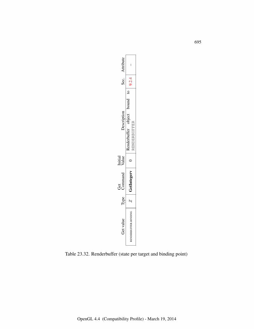
695
Get
valu
eTy
peG
etC
omm
and
Initi
alV
alue
Des
crip
tion
Sec.
Attr
ibut
e
RE
ND
ER
BU
FFE
RB
IND
ING
ZG
etIn
tege
rv0
Ren
derb
uffe
rob
ject
boun
dto
RENDERBUFFER
9.2.
4–
Table 23.32. Renderbuffer (state per target and binding point)
OpenGL 4.4 (Compatibility Profile) - March 19, 2014
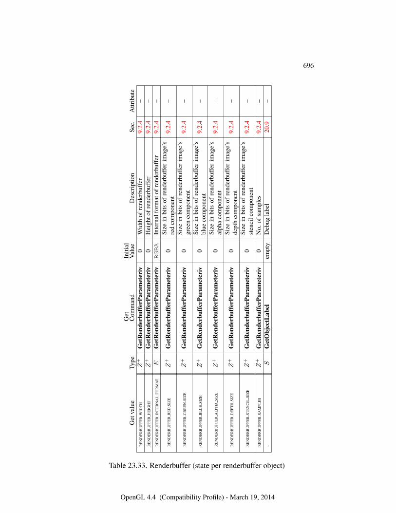
696
Get
valu
eTy
peG
etC
omm
and
Initi
alV
alue
Des
crip
tion
Sec.
Attr
ibut
eR
EN
DE
RB
UFF
ER
WID
TH
Z+
Get
Ren
derb
uffe
rPar
amet
eriv
0W
idth
ofre
nder
buff
er9.
2.4
–R
EN
DE
RB
UFF
ER
HE
IGH
TZ
+G
etR
ende
rbuf
ferP
aram
eter
iv0
Hei
ghto
fren
derb
uffe
r9.
2.4
–R
EN
DE
RB
UFF
ER
INT
ER
NA
LFO
RM
AT
EG
etR
ende
rbuf
ferP
aram
eter
ivRGBA
Inte
rnal
form
atof
rend
erbu
ffer
9.2.
4–
RE
ND
ER
BU
FFE
RR
ED
SIZ
EZ
+G
etR
ende
rbuf
ferP
aram
eter
iv0
Size
inbi
tsof
rend
erbu
ffer
imag
e’s
red
com
pone
nt9.
2.4
–
RE
ND
ER
BU
FFE
RG
RE
EN
SIZ
EZ
+G
etR
ende
rbuf
ferP
aram
eter
iv0
Size
inbi
tsof
rend
erbu
ffer
imag
e’s
gree
nco
mpo
nent
9.2.
4–
RE
ND
ER
BU
FFE
RB
LU
ESI
ZE
Z+
Get
Ren
derb
uffe
rPar
amet
eriv
0Si
zein
bits
ofre
nder
buff
erim
age’
sbl
ueco
mpo
nent
9.2.
4–
RE
ND
ER
BU
FFE
RA
LPH
ASI
ZE
Z+
Get
Ren
derb
uffe
rPar
amet
eriv
0Si
zein
bits
ofre
nder
buff
erim
age’
sal
pha
com
pone
nt9.
2.4
–
RE
ND
ER
BU
FFE
RD
EPT
HSI
ZE
Z+
Get
Ren
derb
uffe
rPar
amet
eriv
0Si
zein
bits
ofre
nder
buff
erim
age’
sde
pth
com
pone
nt9.
2.4
–
RE
ND
ER
BU
FFE
RST
EN
CIL
SIZ
EZ
+G
etR
ende
rbuf
ferP
aram
eter
iv0
Size
inbi
tsof
rend
erbu
ffer
imag
e’s
sten
cilc
ompo
nent
9.2.
4–
RE
ND
ER
BU
FFE
RSA
MPL
ES
Z+
Get
Ren
derb
uffe
rPar
amet
eriv
0N
o.of
sam
ples
9.2.
4–
–S
Get
Obj
ectL
abel
empt
yD
ebug
labe
l20
.9–
Table 23.33. Renderbuffer (state per renderbuffer object)
OpenGL 4.4 (Compatibility Profile) - March 19, 2014
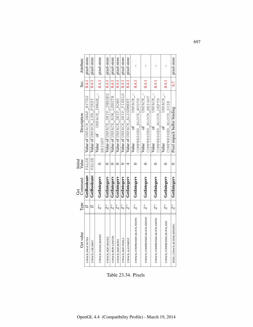
697
Get
valu
eTy
peG
etC
omm
and
Initi
alV
alue
Des
crip
tion
Sec.
Attr
ibut
eU
NPA
CK
SWA
PB
YT
ES
BG
etB
oole
anv
FALSE
Val
ueofUNPACK_SWAP_BYTES
8.4.
1pi
xel-
stor
eU
NPA
CK
LSB
FIR
STB
Get
Boo
lean
vFALSE
Val
ueofUNPACK_LSB_FIRST
8.4.
1pi
xel-
stor
e
UN
PAC
KIM
AG
EH
EIG
HT
Z+
Get
Inte
gerv
0V
alue
ofUNPACK_IMAGE_-
HEIGHT
8.4.
1pi
xel-
stor
e
UN
PAC
KSK
IPIM
AG
ES
Z+
Get
Inte
gerv
0V
alue
ofUNPACK_SKIP_IMAGES
8.4.
1pi
xel-
stor
eU
NPA
CK
RO
WL
EN
GT
HZ
+G
etIn
tege
rv0
Val
ueofUNPACK_ROW_LENGTH
8.4.
1pi
xel-
stor
eU
NPA
CK
SKIP
RO
WS
Z+
Get
Inte
gerv
0V
alue
ofUNPACK_SKIP_ROWS
8.4.
1pi
xel-
stor
eU
NPA
CK
SKIP
PIX
EL
SZ
+G
etIn
tege
rv0
Val
ueofUNPACK_SKIP_PIXELS
8.4.
1pi
xel-
stor
eU
NPA
CK
AL
IGN
ME
NT
Z+
Get
Inte
gerv
4V
alue
ofUNPACK_ALIGNMENT
8.4.
1pi
xel-
stor
e
UN
PAC
KC
OM
PRE
SSE
DB
LO
CK
WID
TH
Z+
Get
Inte
gerv
0V
alue
ofUNPACK_-
COMPRESSED_BLOCK_WIDTH
8.4.
1–
UN
PAC
KC
OM
PRE
SSE
DB
LO
CK
HE
IGH
TZ
+G
etIn
tege
rv0
Val
ueof
UNPACK_-
COMPRESSED_BLOCK_HEIGHT
8.4.
1–
UN
PAC
KC
OM
PRE
SSE
DB
LO
CK
DE
PTH
Z+
Get
Inte
gerv
0V
alue
ofUNPACK_-
COMPRESSED_BLOCK_DEPTH
8.4.
1–
UN
PAC
KC
OM
PRE
SSE
DB
LO
CK
SIZ
EZ
+G
etIn
tege
rv0
Val
ueof
UNPACK_-
COMPRESSED_BLOCK_SIZE
8.4.
1–
PIX
EL
UN
PAC
KB
UFF
ER
BIN
DIN
GZ
+G
etIn
tege
rv0
Pixe
lunp
ack
buff
erbi
ndin
g6.
7pi
xel-
stor
e
Table 23.34. Pixels
OpenGL 4.4 (Compatibility Profile) - March 19, 2014
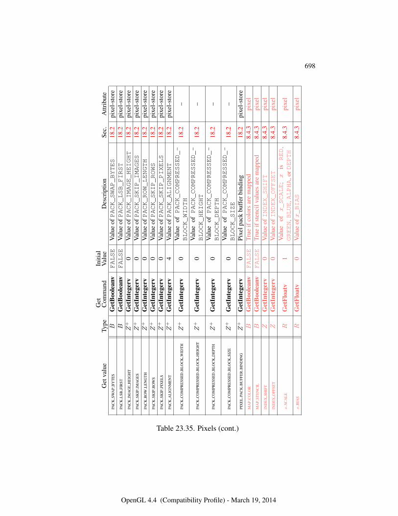
698
Get
valu
eTy
peG
etC
omm
and
Initi
alV
alue
Des
crip
tion
Sec.
Attr
ibut
ePA
CK
SWA
PB
YT
ES
BG
etB
oole
anv
FALSE
Val
ueofPACK_SWAP_BYTES
18.2
pixe
l-st
ore
PAC
KL
SBFI
RST
BG
etB
oole
anv
FALSE
Val
ueofPACK_LSB_FIRST
18.2
pixe
l-st
ore
PAC
KIM
AG
EH
EIG
HT
Z+
Get
Inte
gerv
0V
alue
ofPACK_IMAGE_HEIGHT
18.2
pixe
l-st
ore
PAC
KSK
IPIM
AG
ES
Z+
Get
Inte
gerv
0V
alue
ofPACK_SKIP_IMAGES
18.2
pixe
l-st
ore
PAC
KR
OW
LE
NG
TH
Z+
Get
Inte
gerv
0V
alue
ofPACK_ROW_LENGTH
18.2
pixe
l-st
ore
PAC
KSK
IPR
OW
SZ
+G
etIn
tege
rv0
Val
ueofPACK_SKIP_ROWS
18.2
pixe
l-st
ore
PAC
KSK
IPPI
XE
LS
Z+
Get
Inte
gerv
0V
alue
ofPACK_SKIP_PIXELS
18.2
pixe
l-st
ore
PAC
KA
LIG
NM
EN
TZ
+G
etIn
tege
rv4
Val
ueofPACK_ALIGNMENT
18.2
pixe
l-st
ore
PAC
KC
OM
PRE
SSE
DB
LO
CK
WID
TH
Z+
Get
Inte
gerv
0V
alue
ofPACK_COMPRESSED_-
BLOCK_WIDTH
18.2
–
PAC
KC
OM
PRE
SSE
DB
LO
CK
HE
IGH
TZ
+G
etIn
tege
rv0
Val
ueof
PACK_COMPRESSED_-
BLOCK_HEIGHT
18.2
–
PAC
KC
OM
PRE
SSE
DB
LO
CK
DE
PTH
Z+
Get
Inte
gerv
0V
alue
ofPACK_COMPRESSED_-
BLOCK_DEPTH
18.2
–
PAC
KC
OM
PRE
SSE
DB
LO
CK
SIZ
EZ
+G
etIn
tege
rv0
Val
ueof
PACK_COMPRESSED_-
BLOCK_SIZE
18.2
–
PIX
EL
PAC
KB
UFF
ER
BIN
DIN
GZ
+G
etIn
tege
rv0
Pixe
lpac
kbu
ffer
bind
ing
18.2
pixe
l-st
ore
MA
PC
OL
OR
BG
etB
oole
anv
FALSE
True
ifco
lors
are
map
ped
8.4.
3pi
xel
MA
PST
EN
CIL
BG
etB
oole
anv
FALSE
True
ifst
enci
lval
ues
are
map
ped
8.4.
3pi
xel
IND
EX
SHIF
TZ
Get
Inte
gerv
0V
alue
ofINDEX_SHIFT
8.4.
3pi
xel
IND
EX
OFF
SET
ZG
etIn
tege
rv0
Val
ueofINDEX_OFFSET
8.4.
3pi
xel
xSC
AL
ER
Get
Floa
tv1
Val
ueof
x_SCALE
;x
isRED
,GREEN
,BLUE
,ALPHA
,orDEPTH
8.4.
3pi
xel
xB
IAS
RG
etFl
oatv
0V
alue
ofx_BIAS
8.4.
3pi
xel
Table 23.35. Pixels (cont.)
OpenGL 4.4 (Compatibility Profile) - March 19, 2014
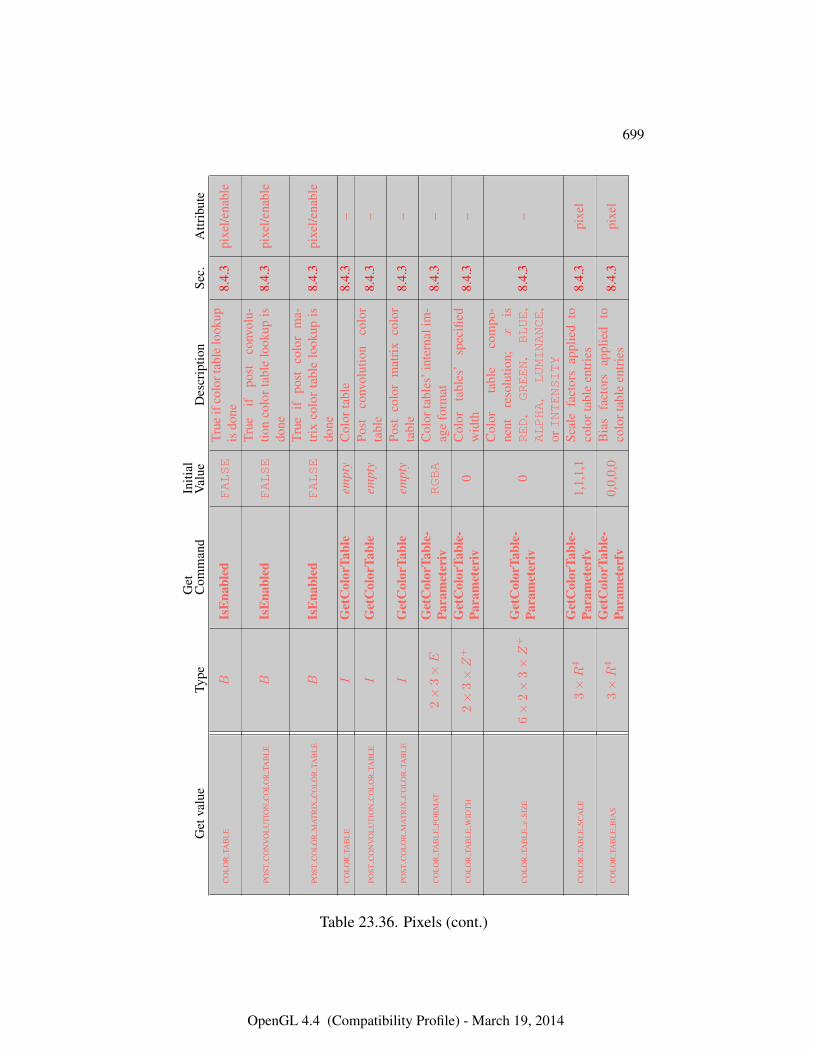
699
Get
valu
eTy
peG
etC
omm
and
Initi
alV
alue
Des
crip
tion
Sec.
Attr
ibut
e
CO
LO
RTA
BL
EB
IsE
nabl
edFALSE
True
ifco
lort
able
look
upis
done
8.4.
3pi
xel/e
nabl
e
POST
CO
NV
OL
UT
ION
CO
LO
RTA
BL
EB
IsE
nabl
edFALSE
True
ifpo
stco
nvol
u-tio
nco
lor
tabl
elo
okup
isdo
ne8.
4.3
pixe
l/ena
ble
POST
CO
LO
RM
AT
RIX
CO
LO
RTA
BL
EB
IsE
nabl
edFALSE
True
ifpo
stco
lor
ma-
trix
colo
rta
ble
look
upis
done
8.4.
3pi
xel/e
nabl
e
CO
LO
RTA
BL
EI
Get
Col
orTa
ble
empt
yC
olor
tabl
e8.
4.3
–
POST
CO
NV
OL
UT
ION
CO
LO
RTA
BL
EI
Get
Col
orTa
ble
empt
yPo
stco
nvol
utio
nco
lor
tabl
e8.
4.3
–
POST
CO
LO
RM
AT
RIX
CO
LO
RTA
BL
EI
Get
Col
orTa
ble
empt
yPo
stco
lor
mat
rix
colo
rta
ble
8.4.
3–
CO
LO
RTA
BL
EFO
RM
AT
2×
3×E
Get
Col
orTa
ble-
Para
met
eriv
RGBA
Col
orta
bles
’int
erna
lim
-ag
efo
rmat
8.4.
3–
CO
LO
RTA
BL
EW
IDT
H2×
3×Z
+G
etC
olor
Tabl
e-Pa
ram
eter
iv0
Col
orta
bles
’sp
ecifi
edw
idth
8.4.
3–
CO
LO
RTA
BL
Ex
SIZ
E6×
2×
3×Z
+G
etC
olor
Tabl
e-Pa
ram
eter
iv0
Col
orta
ble
com
po-
nent
reso
lutio
n;x
isRED
,GREEN
,BLUE
,ALPHA
,LUMINANCE
,orINTENSITY
8.4.
3–
CO
LO
RTA
BL
ESC
AL
E3×R
4G
etC
olor
Tabl
e-Pa
ram
eter
fv1,
1,1,
1Sc
ale
fact
ors
appl
ied
toco
lort
able
entr
ies
8.4.
3pi
xel
CO
LO
RTA
BL
EB
IAS
3×R
4G
etC
olor
Tabl
e-Pa
ram
eter
fv0,
0,0,
0B
ias
fact
ors
appl
ied
toco
lort
able
entr
ies
8.4.
3pi
xel
Table 23.36. Pixels (cont.)
OpenGL 4.4 (Compatibility Profile) - March 19, 2014
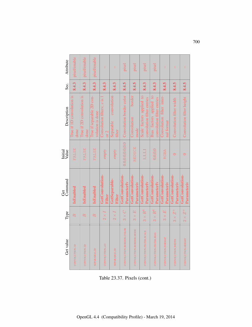
700
Get
valu
eTy
peG
etC
omm
and
Initi
alV
alue
Des
crip
tion
Sec.
Attr
ibut
e
CO
NV
OL
UT
ION
1DB
IsE
nabl
edFALSE
True
if1D
conv
olut
ion
isdo
ne8.
4.3
pixe
l/ena
ble
CO
NV
OL
UT
ION
2DB
IsE
nabl
edFALSE
True
if2D
conv
olut
ion
isdo
ne8.
4.3
pixe
l/ena
ble
SEPA
RA
BL
E2D
BIs
Ena
bled
FALSE
True
ifse
para
ble
2Dco
n-vo
lutio
nis
done
8.4.
3pi
xel/e
nabl
e
CO
NV
OL
UT
ION
xD
2×I
Get
Con
volu
tion-
Filte
rem
pty
Con
volu
tion
filte
rs;x
is1
or2
8.4.
3–
SEPA
RA
BL
E2D
2×I
Get
Sepa
rabl
e-Fi
lter
empt
ySe
para
ble
conv
olut
ion
filte
r8.
4.3
–
CO
NV
OL
UT
ION
BO
RD
ER
CO
LO
R3×C
Get
Con
volu
tion-
Para
met
erfv
0.0,
0.0,
0.0,
0.0
Con
volu
tion
bord
erco
lor
8.4.
5pi
xel
CO
NV
OL
UT
ION
BO
RD
ER
MO
DE
3×E
Get
Con
volu
tion-
Para
met
eriv
REDUCE
Con
volu
tion
bord
erm
ode
8.4.
5pi
xel
CO
NV
OL
UT
ION
FILT
ER
SCA
LE
3×R
4G
etC
onvo
lutio
n-Pa
ram
eter
fv1,
1,1,
1Sc
ale
fact
ors
appl
ied
toco
nvol
utio
nfil
tere
ntri
es8.
4.3
pixe
l
CO
NV
OL
UT
ION
FILT
ER
BIA
S3×R
4G
etC
onvo
lutio
n-Pa
ram
eter
fv0,
0,0,
0B
ias
fact
ors
appl
ied
toco
nvol
utio
nfil
tere
ntri
es8.
4.3
pixe
l
CO
NV
OL
UT
ION
FOR
MA
T3×E
Get
Con
volu
tion-
Para
met
eriv
RGBA
Con
volu
tion
filte
rin
ter-
nalf
orm
at8.
4.5
–
CO
NV
OL
UT
ION
WID
TH
3×Z
+G
etC
onvo
lutio
n-Pa
ram
eter
iv0
Con
volu
tion
filte
rwid
th8.
4.5
–
CO
NV
OL
UT
ION
HE
IGH
T2×Z
+G
etC
onvo
lutio
n-Pa
ram
eter
iv0
Con
volu
tion
filte
rhei
ght
8.4.
5–
Table 23.37. Pixels (cont.)
OpenGL 4.4 (Compatibility Profile) - March 19, 2014
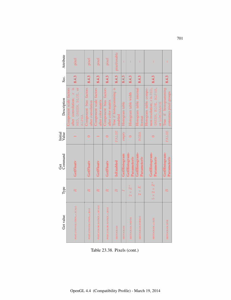
701
Get
valu
eTy
peG
etC
omm
and
Initi
alV
alue
Des
crip
tion
Sec.
Attr
ibut
e
POST
CO
NV
OL
UT
ION
xSC
AL
ER
Get
Floa
tv1
Com
pone
ntsc
ale
fact
ors
afte
rco
nvol
utio
n;x
isRED
,GREEN
,BLUE
,or
ALPHA
8.4.
3pi
xel
POST
CO
NV
OL
UT
ION
xB
IAS
RG
etFl
oatv
0C
ompo
nent
bias
fact
ors
afte
rcon
volu
tion
8.4.
3pi
xel
POST
CO
LO
RM
AT
RIX
xSC
AL
ER
Get
Floa
tv1
Com
pone
ntsc
ale
fact
ors
afte
rcol
orm
atri
x8.
4.3
pixe
l
POST
CO
LO
RM
AT
RIX
xB
IAS
RG
etFl
oatv
0C
ompo
nent
bias
fact
ors
afte
rcol
orm
atri
x8.
4.3
pixe
l
HIS
TOG
RA
MB
IsE
nabl
edFALSE
True
ifhi
stog
ram
min
gis
enab
led
8.4.
3pi
xel/e
nabl
e
HIS
TOG
RA
MI
Get
His
togr
amem
pty
His
togr
amta
ble
8.4.
3–
HIS
TOG
RA
MW
IDT
H2×Z
+G
etH
isto
gram
-Pa
ram
eter
iv0
His
togr
amta
ble
wid
th8.
4.3
–
HIS
TOG
RA
MFO
RM
AT
2×E
Get
His
togr
am-
Para
met
eriv
RGBA
His
togr
amta
ble
inte
rnal
form
at8.
4.3
–
HIS
TOG
RA
Mx
SIZ
E5×
2×Z
+G
etH
isto
gram
-Pa
ram
eter
iv0
His
togr
amta
ble
com
po-
nent
reso
lutio
n;x
isRED
,GREEN
,BLUE
,ALPHA
,orLUMINANCE
8.4.
3–
HIS
TOG
RA
MSI
NK
BG
etH
isto
gram
-Pa
ram
eter
ivFALSE
True
ifhi
stog
ram
min
gco
nsum
espi
xelg
roup
s8.
4.3
–
Table 23.38. Pixels (cont.)
OpenGL 4.4 (Compatibility Profile) - March 19, 2014
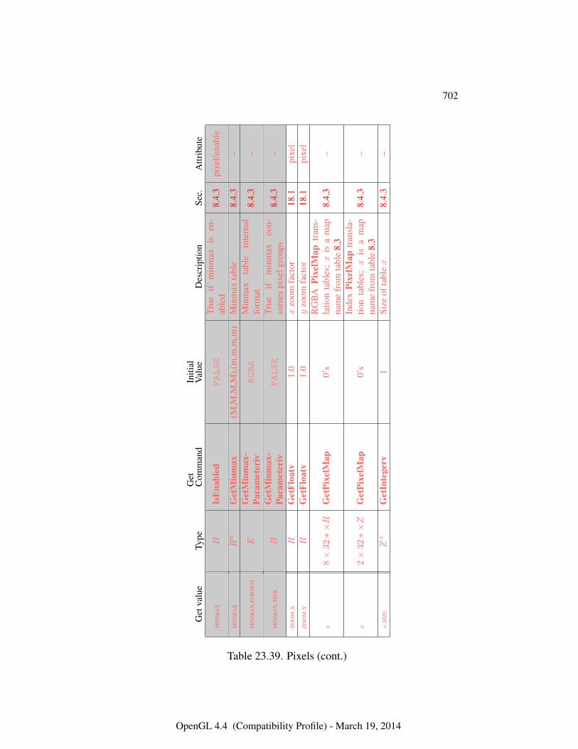
702
Get
valu
eTy
peG
etC
omm
and
Initi
alV
alue
Des
crip
tion
Sec.
Attr
ibut
e
MIN
MA
XB
IsE
nabl
edFALSE
True
ifm
inm
axis
en-
able
d8.
4.3
pixe
l/ena
ble
MIN
MA
XR
nG
etM
inm
ax(M
,M,M
,M),(
m,m
,m,m
)M
inm
axta
ble
8.4.
3–
MIN
MA
XFO
RM
AT
EG
etM
inm
ax-
Para
met
eriv
RGBA
Min
max
tabl
ein
tern
alfo
rmat
8.4.
3–
MIN
MA
XSI
NK
BG
etM
inm
ax-
Para
met
eriv
FALSE
True
ifm
inm
axco
n-su
mes
pixe
lgro
ups
8.4.
3–
ZO
OM
XR
Get
Floa
tv1.
0x
zoom
fact
or18
.1pi
xel
ZO
OM
YR
Get
Floa
tv1.
0y
zoom
fact
or18
.1pi
xel
x8×
32∗×R
Get
Pixe
lMap
0’s
RG
BA
Pixe
lMap
tran
s-la
tion
tabl
es;x
isa
map
nam
efr
omta
ble
8.3
8.4.
3–
x2×
32∗×Z
Get
Pixe
lMap
0’s
Inde
xPi
xelM
aptr
ansl
a-tio
nta
bles
;x
isa
map
nam
efr
omta
ble
8.3
8.4.
3–
xSI
ZE
Z+
Get
Inte
gerv
1Si
zeof
tabl
ex
8.4.
3–
Table 23.39. Pixels (cont.)
OpenGL 4.4 (Compatibility Profile) - March 19, 2014
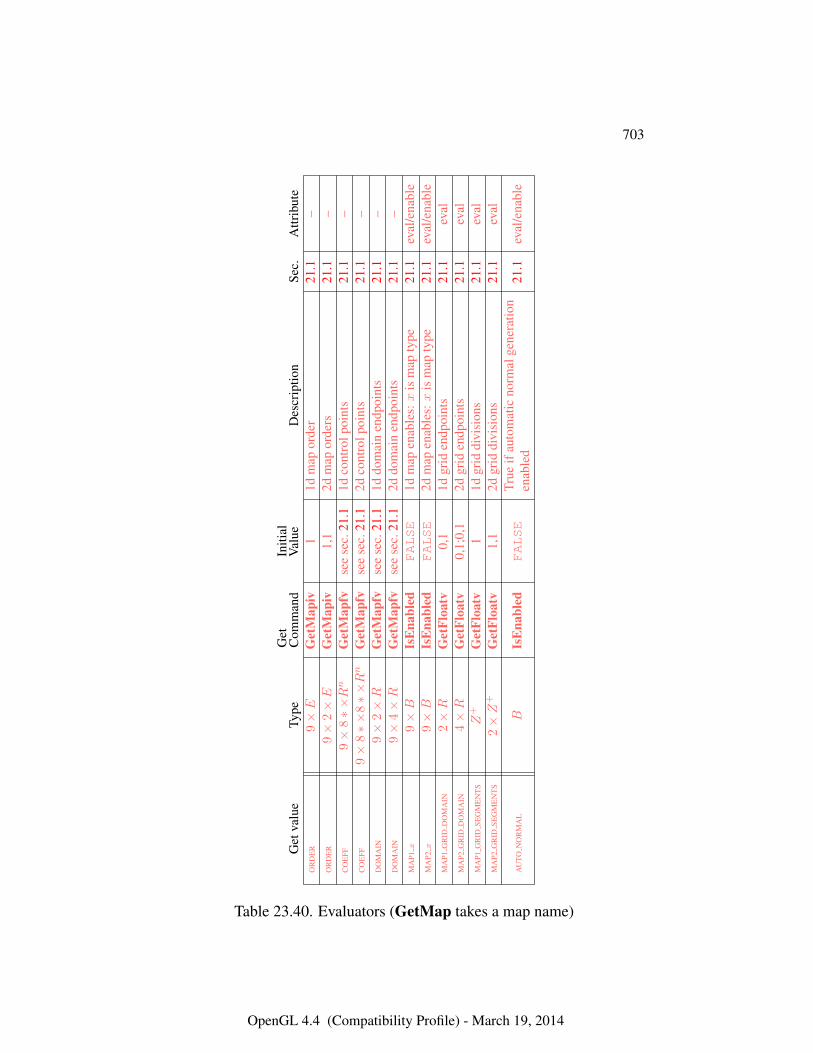
703
Get
valu
eTy
peG
etC
omm
and
Initi
alV
alue
Des
crip
tion
Sec.
Attr
ibut
eO
RD
ER
9×E
Get
Map
iv1
1dm
apor
der
21.1
–O
RD
ER
9×
2×E
Get
Map
iv1,
12d
map
orde
rs21
.1–
CO
EFF
9×
8∗×R
nG
etM
apfv
see
sec.
21.1
1dco
ntro
lpoi
nts
21.1
–C
OE
FF9×
8∗×
8∗×R
nG
etM
apfv
see
sec.
21.1
2dco
ntro
lpoi
nts
21.1
–D
OM
AIN
9×
2×R
Get
Map
fvse
ese
c.21
.11d
dom
ain
endp
oint
s21
.1–
DO
MA
IN9×
4×R
Get
Map
fvse
ese
c.21
.12d
dom
ain
endp
oint
s21
.1–
MA
P1x
9×B
IsE
nabl
edFALSE
1dm
apen
able
s:x
ism
apty
pe21
.1ev
al/e
nabl
eM
AP2
x9×B
IsE
nabl
edFALSE
2dm
apen
able
s:x
ism
apty
pe21
.1ev
al/e
nabl
eM
AP1
GR
IDD
OM
AIN
2×R
Get
Floa
tv0,
11d
grid
endp
oint
s21
.1ev
alM
AP2
GR
IDD
OM
AIN
4×R
Get
Floa
tv0,
1;0,
12d
grid
endp
oint
s21
.1ev
alM
AP1
GR
IDSE
GM
EN
TS
Z+
Get
Floa
tv1
1dgr
iddi
visi
ons
21.1
eval
MA
P2G
RID
SEG
ME
NT
S2×Z
+G
etFl
oatv
1,1
2dgr
iddi
visi
ons
21.1
eval
AU
TON
OR
MA
LB
IsE
nabl
edFALSE
True
ifau
tom
atic
norm
alge
nera
tion
enab
led
21.1
eval
/ena
ble
Table 23.40. Evaluators (GetMap takes a map name)
OpenGL 4.4 (Compatibility Profile) - March 19, 2014
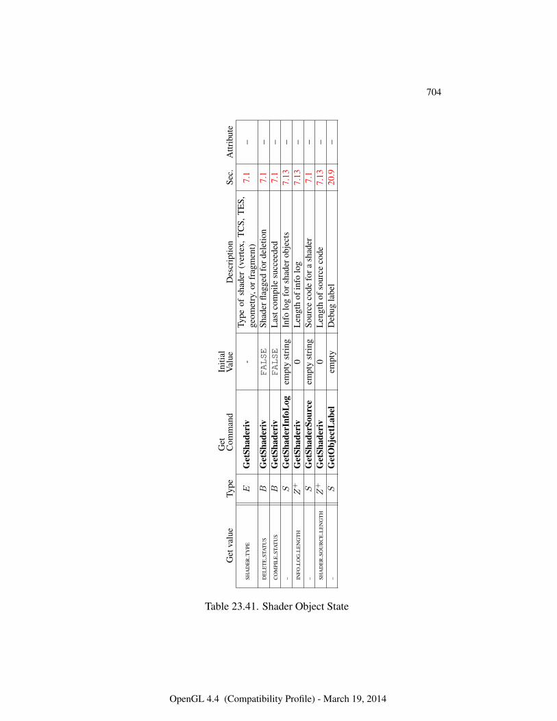
704
Get
valu
eTy
peG
etC
omm
and
Initi
alV
alue
Des
crip
tion
Sec.
Attr
ibut
e
SHA
DE
RT
YPE
EG
etSh
ader
iv-
Type
ofsh
ader
(ver
tex,
TC
S,T
ES,
geom
etry
,orf
ragm
ent)
7.1
–
DE
LE
TE
STA
TU
SB
Get
Shad
eriv
FALSE
Shad
erfla
gged
ford
elet
ion
7.1
–C
OM
PIL
EST
AT
US
BG
etSh
ader
ivFALSE
Las
tcom
pile
succ
eede
d7.
1–
–S
Get
Shad
erIn
foL
ogem
pty
stri
ngIn
folo
gfo
rsha
dero
bjec
ts7.
13–
INFO
LO
GL
EN
GT
HZ
+G
etSh
ader
iv0
Len
gth
ofin
folo
g7.
13–
–S
Get
Shad
erSo
urce
empt
yst
ring
Sour
ceco
defo
rash
ader
7.1
–SH
AD
ER
SOU
RC
EL
EN
GT
HZ
+G
etSh
ader
iv0
Len
gth
ofso
urce
code
7.13
––
SG
etO
bjec
tLab
elem
pty
Deb
ugla
bel
20.9
–
Table 23.41. Shader Object State
OpenGL 4.4 (Compatibility Profile) - March 19, 2014
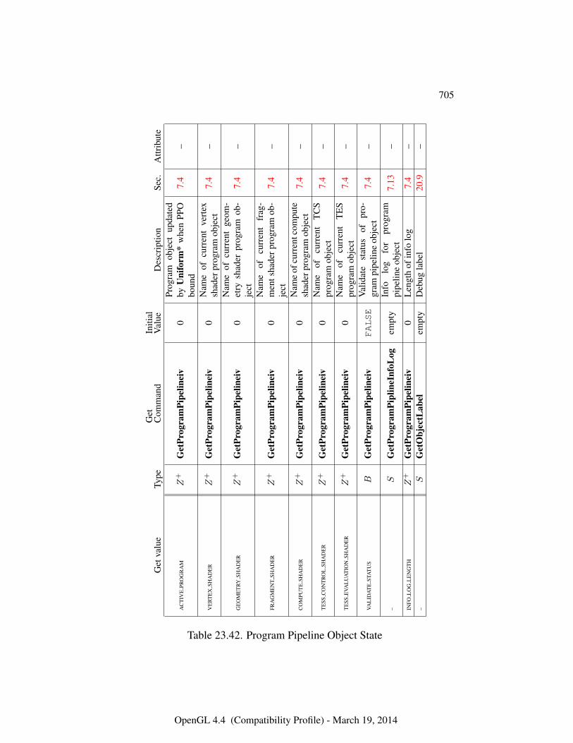
705
Get
valu
eTy
peG
etC
omm
and
Initi
alV
alue
Des
crip
tion
Sec.
Attr
ibut
e
AC
TIV
EPR
OG
RA
MZ
+G
etPr
ogra
mPi
pelin
eiv
0Pr
ogra
mob
ject
upda
ted
byU
nifo
rm*
whe
nPP
Obo
und
7.4
–
VE
RT
EX
SHA
DE
RZ
+G
etPr
ogra
mPi
pelin
eiv
0N
ame
ofcu
rren
tve
rtex
shad
erpr
ogra
mob
ject
7.4
–
GE
OM
ET
RYSH
AD
ER
Z+
Get
Prog
ram
Pipe
linei
v0
Nam
eof
curr
ent
geom
-et
rysh
ader
prog
ram
ob-
ject
7.4
–
FRA
GM
EN
TSH
AD
ER
Z+
Get
Prog
ram
Pipe
linei
v0
Nam
eof
curr
ent
frag
-m
ents
hade
rpro
gram
ob-
ject
7.4
–
CO
MPU
TE
SHA
DE
RZ
+G
etPr
ogra
mPi
pelin
eiv
0N
ame
ofcu
rren
tcom
pute
shad
erpr
ogra
mob
ject
7.4
–
TE
SSC
ON
TR
OL
SHA
DE
RZ
+G
etPr
ogra
mPi
pelin
eiv
0N
ame
ofcu
rren
tT
CS
prog
ram
obje
ct7.
4–
TE
SSE
VAL
UA
TIO
NSH
AD
ER
Z+
Get
Prog
ram
Pipe
linei
v0
Nam
eof
curr
ent
TE
Spr
ogra
mob
ject
7.4
–
VAL
IDA
TE
STA
TU
SB
Get
Prog
ram
Pipe
linei
vFALSE
Val
idat
est
atus
ofpr
o-gr
ampi
pelin
eob
ject
7.4
–
–S
Get
Prog
ram
Pipl
ineI
nfoL
ogem
pty
Info
log
for
prog
ram
pipe
line
obje
ct7.
13–
INFO
LO
GL
EN
GT
HZ
+G
etPr
ogra
mPi
pelin
eiv
0L
engt
hof
info
log
7.4
––
SG
etO
bjec
tLab
elem
pty
Deb
ugla
bel
20.9
–
Table 23.42. Program Pipeline Object State
OpenGL 4.4 (Compatibility Profile) - March 19, 2014
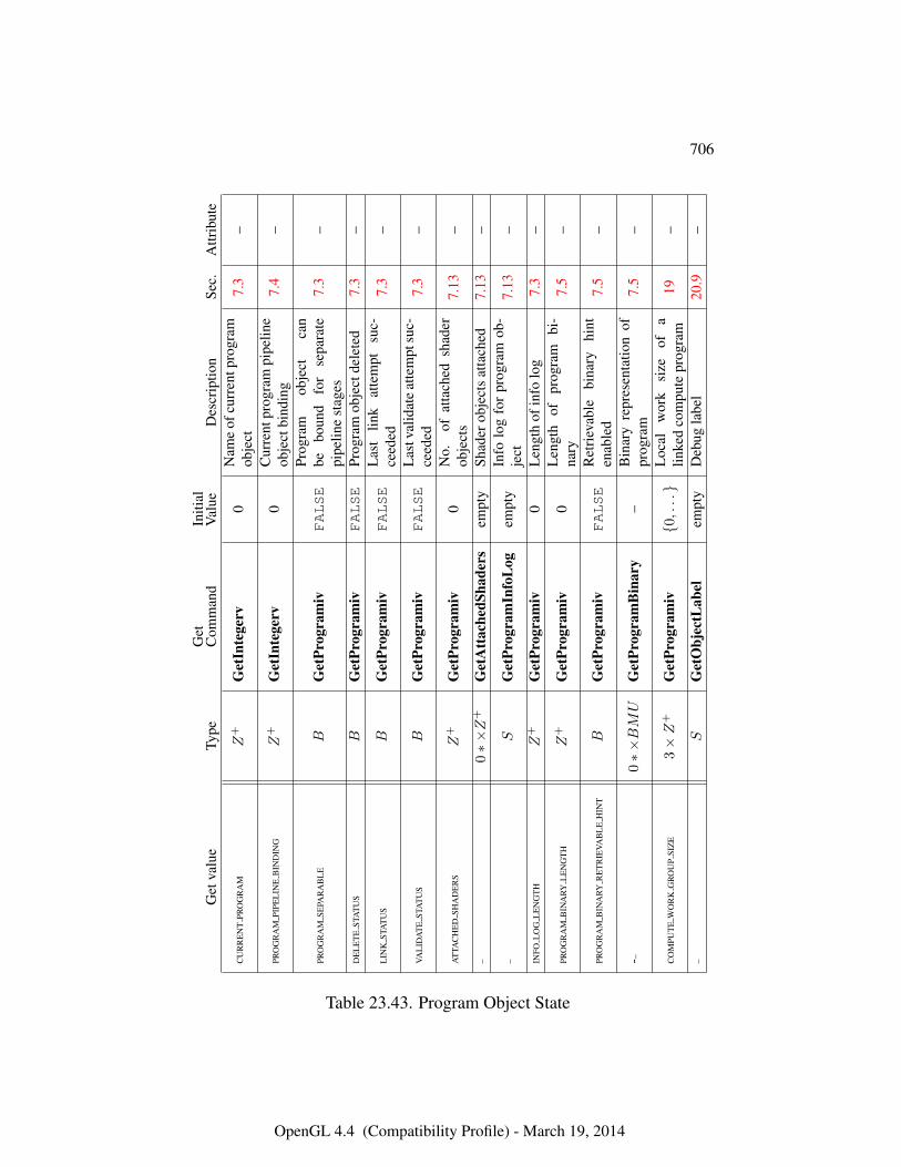
706
Get
valu
eTy
peG
etC
omm
and
Initi
alV
alue
Des
crip
tion
Sec.
Attr
ibut
e
CU
RR
EN
TPR
OG
RA
MZ
+G
etIn
tege
rv0
Nam
eof
curr
entp
rogr
amob
ject
7.3
–
PRO
GR
AM
PIPE
LIN
EB
IND
ING
Z+
Get
Inte
gerv
0C
urre
ntpr
ogra
mpi
pelin
eob
ject
bind
ing
7.4
–
PRO
GR
AM
SEPA
RA
BL
EB
Get
Prog
ram
ivFALSE
Prog
ram
obje
ctca
nbe
boun
dfo
rse
para
tepi
pelin
est
ages
7.3
–
DE
LE
TE
STA
TU
SB
Get
Prog
ram
ivFALSE
Prog
ram
obje
ctde
lete
d7.
3–
LIN
KST
AT
US
BG
etPr
ogra
miv
FALSE
Las
tlin
kat
tem
ptsu
c-ce
eded
7.3
–
VAL
IDA
TE
STA
TU
SB
Get
Prog
ram
ivFALSE
Las
tval
idat
eat
tem
ptsu
c-ce
eded
7.3
–
AT
TAC
HE
DSH
AD
ER
SZ
+G
etPr
ogra
miv
0N
o.of
atta
ched
shad
erob
ject
s7.
13–
–0∗×Z
+G
etA
ttac
hedS
hade
rsem
pty
Shad
erob
ject
sat
tach
ed7.
13–
–S
Get
Prog
ram
Info
Log
empt
yIn
folo
gfo
rpr
ogra
mob
-je
ct7.
13–
INFO
LO
GL
EN
GT
HZ
+G
etPr
ogra
miv
0L
engt
hof
info
log
7.3
–
PRO
GR
AM
BIN
ARY
LE
NG
TH
Z+
Get
Prog
ram
iv0
Len
gth
ofpr
ogra
mbi
-na
ry7.
5–
PRO
GR
AM
BIN
ARY
RE
TR
IEVA
BL
EH
INT
BG
etPr
ogra
miv
FALSE
Ret
riev
able
bina
ryhi
nten
able
d7.
5–
-–0∗×BMU
Get
Prog
ram
Bin
ary
–B
inar
yre
pres
enta
tion
ofpr
ogra
m7.
5–
CO
MPU
TE
WO
RK
GR
OU
PSI
ZE
3×Z
+G
etPr
ogra
miv
{0,...}
Loc
alw
ork
size
ofa
linke
dco
mpu
tepr
ogra
m19
–
–S
Get
Obj
ectL
abel
empt
yD
ebug
labe
l20
.9–
Table 23.43. Program Object State
OpenGL 4.4 (Compatibility Profile) - March 19, 2014
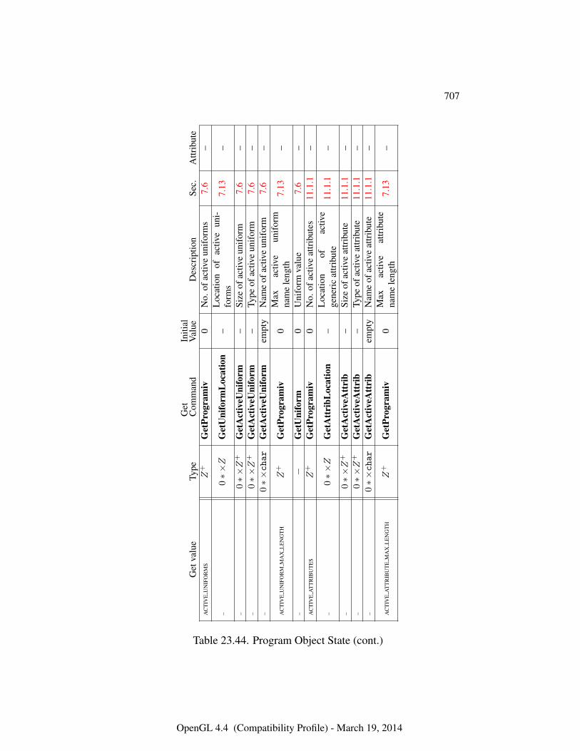
707
Get
valu
eTy
peG
etC
omm
and
Initi
alV
alue
Des
crip
tion
Sec.
Attr
ibut
eA
CT
IVE
UN
IFO
RM
SZ
+G
etPr
ogra
miv
0N
o.of
activ
eun
ifor
ms
7.6
–
–0∗×Z
Get
Uni
form
Loc
atio
n–
Loc
atio
nof
activ
eun
i-fo
rms
7.13
–
–0∗×Z
+G
etA
ctiv
eUni
form
–Si
zeof
activ
eun
ifor
m7.
6–
–0∗×Z
+G
etA
ctiv
eUni
form
–Ty
peof
activ
eun
ifor
m7.
6–
–0∗×char
Get
Act
iveU
nifo
rmem
pty
Nam
eof
activ
eun
ifor
m7.
6–
AC
TIV
EU
NIF
OR
MM
AX
LE
NG
TH
Z+
Get
Prog
ram
iv0
Max
activ
eun
ifor
mna
me
leng
th7.
13–
–−
Get
Uni
form
0U
nifo
rmva
lue
7.6
–A
CT
IVE
AT
TR
IBU
TE
SZ
+G
etPr
ogra
miv
0N
o.of
activ
eat
trib
utes
11.1
.1–
–0∗×Z
Get
Att
ribL
ocat
ion
–L
ocat
ion
ofac
tive
gene
ric
attr
ibut
e11
.1.1
–
–0∗×Z
+G
etA
ctiv
eAtt
rib
–Si
zeof
activ
eat
trib
ute
11.1
.1–
–0∗×Z
+G
etA
ctiv
eAtt
rib
–Ty
peof
activ
eat
trib
ute
11.1
.1–
–0∗×char
Get
Act
iveA
ttri
bem
pty
Nam
eof
activ
eat
trib
ute
11.1
.1–
AC
TIV
EA
TT
RIB
UT
EM
AX
LE
NG
TH
Z+
Get
Prog
ram
iv0
Max
activ
eat
trib
ute
nam
ele
ngth
7.13
–
Table 23.44. Program Object State (cont.)
OpenGL 4.4 (Compatibility Profile) - March 19, 2014
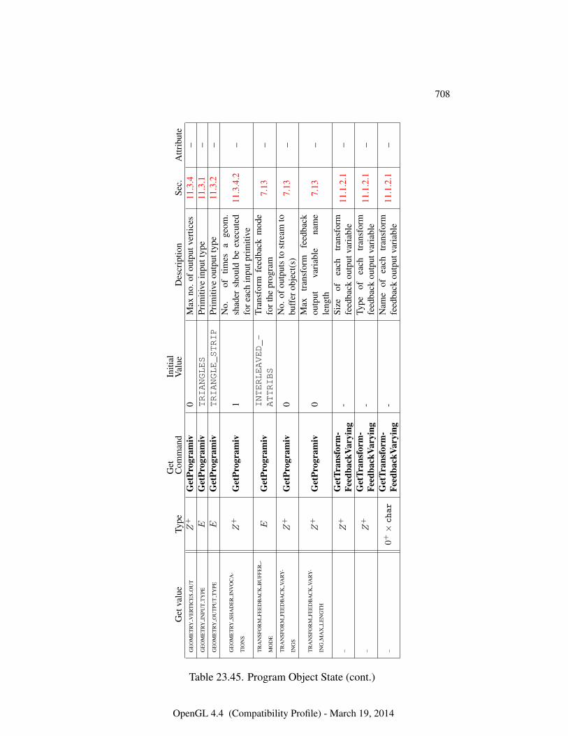
708
Get
valu
eTy
peG
etC
omm
and
Initi
alV
alue
Des
crip
tion
Sec.
Attr
ibut
eG
EO
ME
TRY
VE
RT
ICE
SO
UT
Z+
Get
Prog
ram
iv0
Max
no.o
fout
putv
ertic
es11
.3.4
–G
EO
ME
TRY
INPU
TT
YPE
EG
etPr
ogra
miv
TRIANGLES
Prim
itive
inpu
ttyp
e11
.3.1
–G
EO
ME
TRY
OU
TPU
TT
YPE
EG
etPr
ogra
miv
TRIANGLE_STRIP
Prim
itive
outp
utty
pe11
.3.2
–
GE
OM
ET
RYSH
AD
ER
INV
OC
A-
TIO
NS
Z+
Get
Prog
ram
iv1
No.
oftim
esa
geom
.sh
ader
shou
ldbe
exec
uted
fore
ach
inpu
tpri
miti
ve11
.3.4
.2–
TR
AN
SFO
RM
FEE
DB
AC
KB
UFF
ER
-
MO
DE
EG
etPr
ogra
miv
INTERLEAVED_-
ATTRIBS
Tran
sfor
mfe
edba
ckm
ode
fort
hepr
ogra
m7.
13–
TR
AN
SFO
RM
FEE
DB
AC
KVA
RY-
ING
SZ
+G
etPr
ogra
miv
0N
o.of
outp
uts
tost
ream
tobu
ffer
obje
ct(s
)7.
13–
TR
AN
SFO
RM
FEE
DB
AC
KVA
RY-
ING
MA
XL
EN
GT
HZ
+G
etPr
ogra
miv
0M
axtr
ansf
orm
feed
back
outp
utva
riab
lena
me
leng
th7.
13–
–Z
+G
etTr
ansf
orm
-Fe
edba
ckVa
ryin
g-
Size
ofea
chtr
ansf
orm
feed
back
outp
utva
riab
le11
.1.2
.1–
–Z
+G
etTr
ansf
orm
-Fe
edba
ckVa
ryin
g-
Type
ofea
chtr
ansf
orm
feed
back
outp
utva
riab
le11
.1.2
.1–
–0+×char
Get
Tran
sfor
m-
Feed
back
Vary
ing
-N
ame
ofea
chtr
ansf
orm
feed
back
outp
utva
riab
le11
.1.2
.1–
Table 23.45. Program Object State (cont.)
OpenGL 4.4 (Compatibility Profile) - March 19, 2014
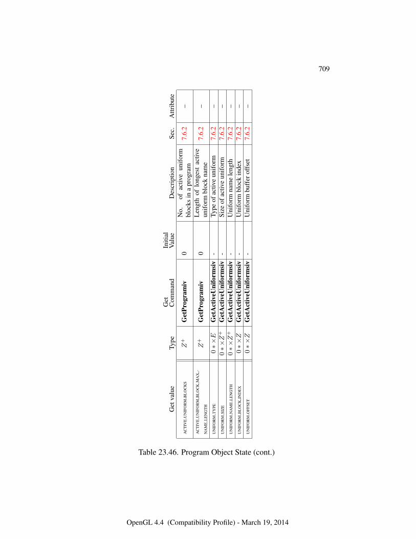
709
Get
valu
eTy
peG
etC
omm
and
Initi
alV
alue
Des
crip
tion
Sec.
Attr
ibut
e
AC
TIV
EU
NIF
OR
MB
LO
CK
SZ
+G
etPr
ogra
miv
0N
o.of
activ
eun
ifor
mbl
ocks
ina
prog
ram
7.6.
2–
AC
TIV
EU
NIF
OR
MB
LO
CK
MA
X-
NA
ME
LE
NG
TH
Z+
Get
Prog
ram
iv0
Len
gth
oflo
nges
tac
tive
unif
orm
bloc
kna
me
7.6.
2–
UN
IFO
RM
TY
PE0∗×E
Get
Act
iveU
nifo
rmsi
v-
Type
ofac
tive
unif
orm
7.6.
2–
UN
IFO
RM
SIZ
E0∗×Z
+G
etA
ctiv
eUni
form
siv
-Si
zeof
activ
eun
ifor
m7.
6.2
–U
NIF
OR
MN
AM
EL
EN
GT
H0∗×Z
+G
etA
ctiv
eUni
form
siv
-U
nifo
rmna
me
leng
th7.
6.2
–U
NIF
OR
MB
LO
CK
IND
EX
0∗×Z
Get
Act
iveU
nifo
rmsi
v-
Uni
form
bloc
kin
dex
7.6.
2–
UN
IFO
RM
OFF
SET
0∗×Z
Get
Act
iveU
nifo
rmsi
v-
Uni
form
buff
erof
fset
7.6.
2–
Table 23.46. Program Object State (cont.)
OpenGL 4.4 (Compatibility Profile) - March 19, 2014
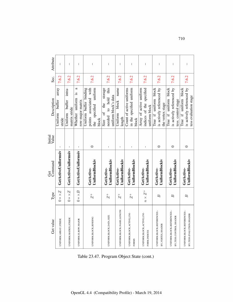
710
Get
valu
eTy
peG
etC
omm
and
Initi
alV
alue
Des
crip
tion
Sec.
Attr
ibut
e
UN
IFO
RM
AR
RA
YST
RID
E0∗×Z
Get
Act
iveU
nifo
rmsi
v-
Uni
form
buff
erar
ray
stri
de7.
6.2
–
UN
IFO
RM
MA
TR
IXST
RID
E0∗×Z
Get
Act
iveU
nifo
rmsi
v-
Uni
form
buff
erin
tra-
mat
rix
stri
de7.
6.2
–
UN
IFO
RM
ISR
OW
MA
JOR
0∗×B
Get
Act
iveU
nifo
rmsi
v-
Whe
ther
unif
orm
isa
row
-maj
orm
atri
x7.
6.2
–
UN
IFO
RM
BL
OC
KB
IND
ING
Z+
Get
Act
ive-
Uni
form
Blo
ckiv
0
Uni
form
buff
erbi
ndin
gpo
ints
asso
ciat
edw
ithth
esp
ecifi
edun
ifor
mbl
ock
7.6.
2–
UN
IFO
RM
BL
OC
KD
ATA
SIZ
EZ
+G
etA
ctiv
e-U
nifo
rmB
lock
iv-
Size
ofth
est
orag
ene
eded
toho
ldth
isun
ifor
mbl
ock’
sda
ta7.
6.2
–
UN
IFO
RM
BL
OC
KN
AM
EL
EN
GT
HZ
+G
etA
ctiv
e-U
nifo
rmB
lock
iv-
Uni
form
bloc
kna
me
leng
th7.
6.2
–
UN
IFO
RM
BL
OC
KA
CT
IVE
UN
I-
FOR
MS
Z+
Get
Act
ive-
Uni
form
Blo
ckiv
-C
ount
ofac
tive
unif
orm
sin
the
spec
ified
unif
orm
bloc
k7.
6.2
–
UN
IFO
RM
BL
OC
KA
CT
IVE
UN
I-
FOR
MIN
DIC
ES
n×Z
+G
etA
ctiv
e-U
nifo
rmB
lock
iv-
Arr
ayof
activ
eun
ifor
min
dice
sof
the
spec
ified
unif
orm
bloc
k7.
6.2
–
UN
IFO
RM
BL
OC
KR
EFE
RE
NC
ED
-
BY
VE
RT
EX
SHA
DE
RB
Get
Act
ive-
Uni
form
Blo
ckiv
0Tr
ueif
unif
orm
bloc
kis
activ
ely
refe
renc
edby
the
vert
exst
age
7.6.
2–
UN
IFO
RM
BL
OC
KR
EFE
RE
NC
ED
-
BY
TE
SSC
ON
TR
OL
SHA
DE
RB
Get
Act
ive-
Uni
form
Blo
ckiv
0Tr
ueif
unif
orm
bloc
kis
activ
ely
refe
renc
edby
tess
.con
trol
stag
e7.
6.2
–
UN
IFO
RM
BL
OC
KR
EFE
RE
NC
ED
-
BY
TE
SSE
VAL
UT
ION
SHA
DE
RB
Get
Act
ive-
Uni
form
Blo
ckiv
0Tr
ueif
unif
orm
bloc
kis
activ
ely
refe
renc
edby
tess
eval
uatio
nst
age
7.6.
2–
Table 23.47. Program Object State (cont.)
OpenGL 4.4 (Compatibility Profile) - March 19, 2014
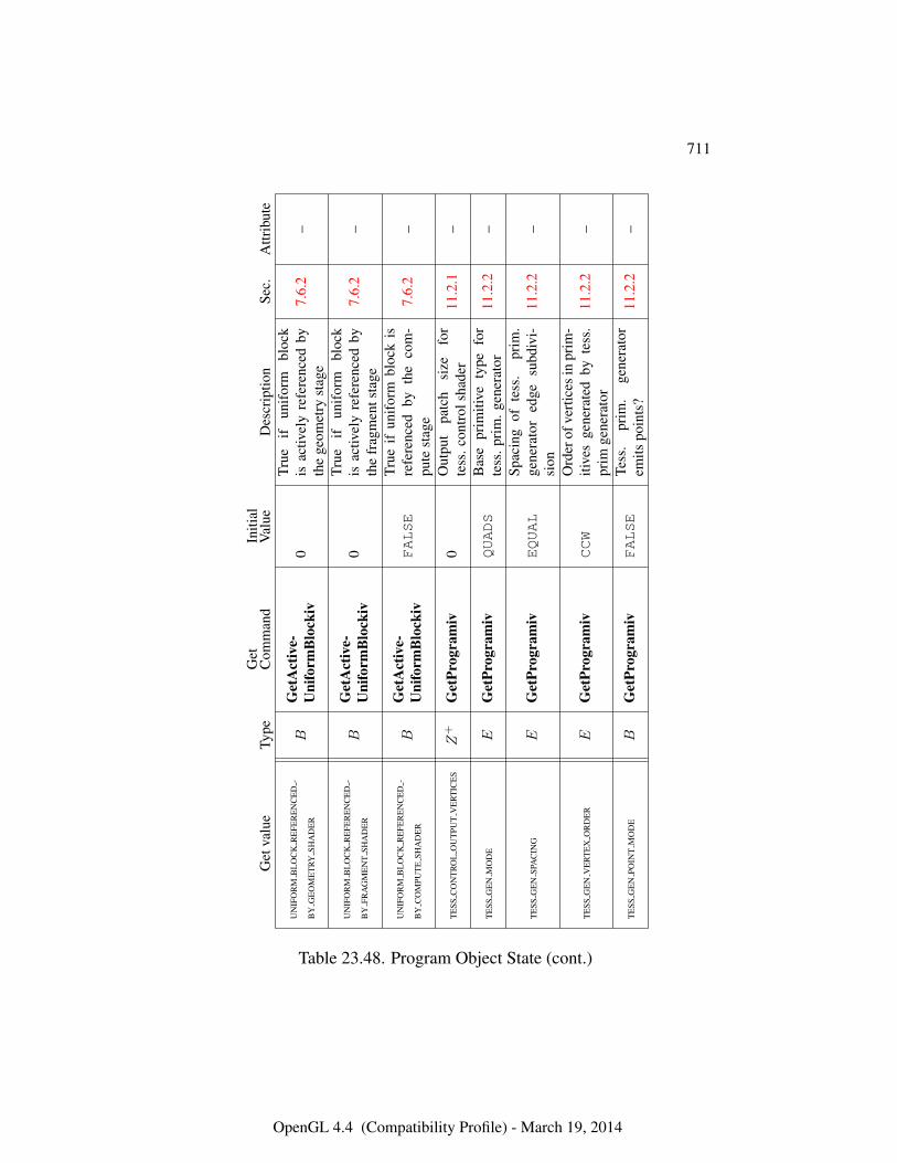
711
Get
valu
eTy
peG
etC
omm
and
Initi
alV
alue
Des
crip
tion
Sec.
Attr
ibut
e
UN
IFO
RM
BL
OC
KR
EFE
RE
NC
ED
-
BY
GE
OM
ET
RYSH
AD
ER
BG
etA
ctiv
e-U
nifo
rmB
lock
iv0
True
ifun
ifor
mbl
ock
isac
tivel
yre
fere
nced
byth
ege
omet
ryst
age
7.6.
2–
UN
IFO
RM
BL
OC
KR
EFE
RE
NC
ED
-
BY
FRA
GM
EN
TSH
AD
ER
BG
etA
ctiv
e-U
nifo
rmB
lock
iv0
True
ifun
ifor
mbl
ock
isac
tivel
yre
fere
nced
byth
efr
agm
ents
tage
7.6.
2–
UN
IFO
RM
BL
OC
KR
EFE
RE
NC
ED
-
BY
CO
MPU
TE
SHA
DE
RB
Get
Act
ive-
Uni
form
Blo
ckiv
FALSE
True
ifun
ifor
mbl
ock
isre
fere
nced
byth
eco
m-
pute
stag
e7.
6.2
–
TE
SSC
ON
TR
OL
OU
TPU
TV
ER
TIC
ES
Z+
Get
Prog
ram
iv0
Out
put
patc
hsi
zefo
rte
ss.c
ontr
olsh
ader
11.2
.1–
TE
SSG
EN
MO
DE
EG
etPr
ogra
miv
QUADS
Bas
epr
imiti
vety
pefo
rte
ss.p
rim
.gen
erat
or11
.2.2
–
TE
SSG
EN
SPA
CIN
GE
Get
Prog
ram
ivEQUAL
Spac
ing
ofte
ss.
prim
.ge
nera
tor
edge
subd
ivi-
sion
11.2
.2–
TE
SSG
EN
VE
RT
EX
OR
DE
RE
Get
Prog
ram
ivCCW
Ord
erof
vert
ices
inpr
im-
itive
sge
nera
ted
byte
ss.
prim
gene
rato
r11
.2.2
–
TE
SSG
EN
POIN
TM
OD
EB
Get
Prog
ram
ivFALSE
Tess
.pr
im.
gene
rato
rem
itspo
ints
?11
.2.2
–
Table 23.48. Program Object State (cont.)
OpenGL 4.4 (Compatibility Profile) - March 19, 2014
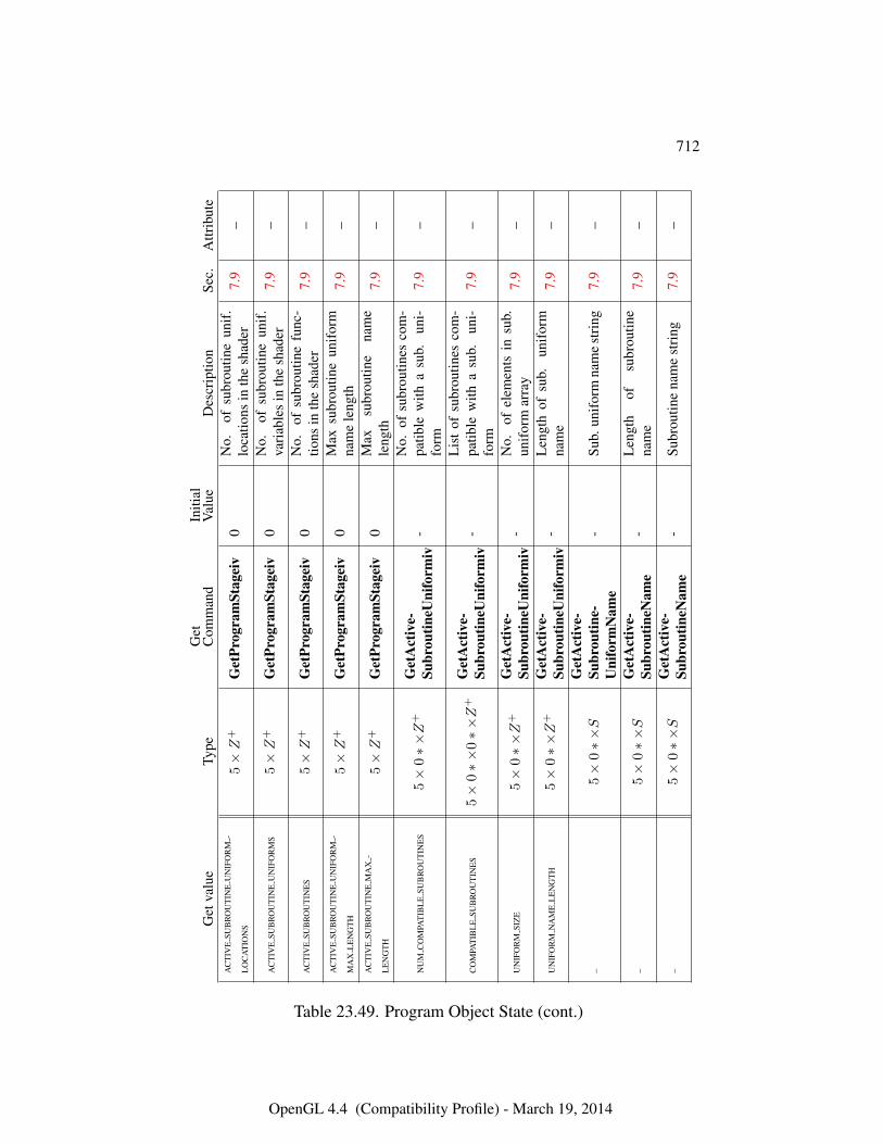
712
Get
valu
eTy
peG
etC
omm
and
Initi
alV
alue
Des
crip
tion
Sec.
Attr
ibut
eA
CT
IVE
SUB
RO
UT
INE
UN
IFO
RM
-
LO
CA
TIO
NS
5×Z
+G
etPr
ogra
mSt
agei
v0
No.
ofsu
brou
tine
unif
.lo
catio
nsin
the
shad
er7.
9–
AC
TIV
ESU
BR
OU
TIN
EU
NIF
OR
MS
5×Z
+G
etPr
ogra
mSt
agei
v0
No.
ofsu
brou
tine
unif
.va
riab
les
inth
esh
ader
7.9
–
AC
TIV
ESU
BR
OU
TIN
ES
5×Z
+G
etPr
ogra
mSt
agei
v0
No.
ofsu
brou
tine
func
-tio
nsin
the
shad
er7.
9–
AC
TIV
ESU
BR
OU
TIN
EU
NIF
OR
M-
MA
XL
EN
GT
H5×Z
+G
etPr
ogra
mSt
agei
v0
Max
subr
outin
eun
ifor
mna
me
leng
th7.
9–
AC
TIV
ESU
BR
OU
TIN
EM
AX
-
LE
NG
TH
5×Z
+G
etPr
ogra
mSt
agei
v0
Max
subr
outin
ena
me
leng
th7.
9–
NU
MC
OM
PAT
IBL
ESU
BR
OU
TIN
ES
5×
0∗×Z
+G
etA
ctiv
e-Su
brou
tineU
nifo
rmiv
-N
o.of
subr
outin
esco
m-
patib
lew
itha
sub.
uni-
form
7.9
–
CO
MPA
TIB
LE
SUB
RO
UT
INE
S5×
0∗×
0∗×Z
+G
etA
ctiv
e-Su
brou
tineU
nifo
rmiv
-L
ist
ofsu
brou
tines
com
-pa
tible
with
asu
b.un
i-fo
rm7.
9–
UN
IFO
RM
SIZ
E5×
0∗×Z
+G
etA
ctiv
e-Su
brou
tineU
nifo
rmiv
-N
o.of
elem
ents
insu
b.un
ifor
mar
ray
7.9
–
UN
IFO
RM
NA
ME
LE
NG
TH
5×
0∗×Z
+G
etA
ctiv
e-Su
brou
tineU
nifo
rmiv
-L
engt
hof
sub.
unif
orm
nam
e7.
9–
–5×
0∗×S
Get
Act
ive-
Subr
outin
e-U
nifo
rmN
ame
-Su
b.un
ifor
mna
me
stri
ng7.
9–
–5×
0∗×S
Get
Act
ive-
Subr
outin
eNam
e-
Len
gth
ofsu
brou
tine
nam
e7.
9–
–5×
0∗×S
Get
Act
ive-
Subr
outin
eNam
e-
Subr
outin
ena
me
stri
ng7.
9–
Table 23.49. Program Object State (cont.)
OpenGL 4.4 (Compatibility Profile) - March 19, 2014
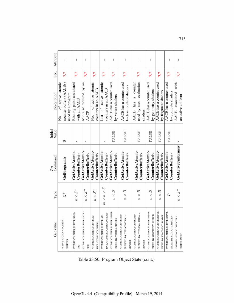
713
Get
valu
eTy
peG
etC
omm
and
Initi
alV
alue
Des
crip
tion
Sec.
Attr
ibut
e
AC
TIV
EA
TOM
ICC
OU
NT
ER
-
BU
FFE
RS
Z+
Get
Prog
ram
iv0
No.
ofac
tive
atom
icco
unte
rbuf
fers
(AA
CB
s)us
edby
apr
ogra
m7.
7–
ATO
MIC
CO
UN
TE
RB
UFF
ER
BIN
D-
ING
n×Z
+G
etA
ctiv
eAto
mic
-C
ount
erB
uffe
riv
-B
indi
ngpo
int
asso
ciat
edw
ithan
AA
CB
7.7
–
ATO
MIC
CO
UN
TE
RB
UFF
ER
DA
TA-
SIZ
En×Z
+G
etA
ctiv
eAto
mic
-C
ount
erB
uffe
riv
-M
insi
zere
quir
edby
anA
AC
B7.
7–
ATO
MIC
CO
UN
TE
RB
UFF
ER
AC
-
TIV
EA
TOM
ICC
OU
NT
ER
Sn×Z
+G
etA
ctiv
eAto
mic
-C
ount
erB
uffe
riv
-N
o.of
activ
eat
omic
coun
ters
inan
AA
CB
7.7
–
ATO
MIC
CO
UN
TE
RB
UFF
ER
AC
-
TIV
EA
TOM
ICC
OU
NT
ER
IND
ICE
Sm×n×Z
+G
etA
ctiv
eAto
mic
-C
ount
erB
uffe
riv
-L
ist
ofac
tive
atom
icco
unte
rsin
anA
AC
B7.
7–
ATO
MIC
CO
UN
TE
RB
UFF
ER
RE
FER
-
EN
CE
DB
YV
ER
TE
XSH
AD
ER
n×B
Get
Act
iveA
tom
ic-
Cou
nter
Buf
feri
vFALSE
AA
CB
hasa
coun
teru
sed
byve
rtex
shad
ers
7.7
–
ATO
MIC
CO
UN
TE
RB
UFF
ER
RE
F-
ER
EN
CE
DB
YT
ESS
CO
NT
RO
L-
SHA
DE
R
n×B
Get
Act
iveA
tom
ic-
Cou
nter
Buf
feri
vFALSE
AA
CB
hasa
coun
teru
sed
byte
ss.c
ontr
olsh
ader
s7.
7–
ATO
MIC
CO
UN
TE
RB
UFF
ER
RE
F-
ER
EN
CE
DB
YT
ESS
EVA
LU
TIO
N-
SHA
DE
R
n×B
Get
Act
iveA
tom
ic-
Cou
nter
Buf
feri
vFALSE
AA
CB
has
aco
unte
rus
edby
tess
.ev
alua
tion
shad
ers
7.7
–
ATO
MIC
CO
UN
TE
RB
UFF
ER
RE
FER
-
EN
CE
DB
YG
EO
ME
TRY
SHA
DE
Rn×B
Get
Act
iveA
tom
ic-
Cou
nter
Buf
feri
vFALSE
AA
CB
hasa
coun
teru
sed
byge
omet
rysh
ader
s7.
7–
ATO
MIC
CO
UN
TE
RB
UFF
ER
RE
FER
-
EN
CE
DB
YFR
AG
ME
NT
SHA
DE
Rn×B
Get
Act
iveA
tom
ic-
Cou
nter
Buf
feri
vFALSE
AA
CB
hasa
coun
teru
sed
byfr
agm
ents
hade
rs7.
7–
ATO
MIC
CO
UN
TE
RB
UFF
ER
RE
FER
-
EN
CE
DB
YC
OM
PUT
ESH
AD
ER
BG
etA
ctiv
eAto
mic
-C
ount
erB
uffe
riv
FALSE
AA
CB
hasa
coun
teru
sed
byco
mpu
tesh
ader
s7.
7–
UN
IFO
RM
ATO
MIC
CO
UN
TE
R-
BU
FFE
RIN
DE
Xn×Z
+G
etA
ctiv
eUni
form
siv
-A
AC
Bas
soci
ated
with
anac
tive
unif
orm
7.7
–
Table 23.50. Program Object State (cont.)
OpenGL 4.4 (Compatibility Profile) - March 19, 2014
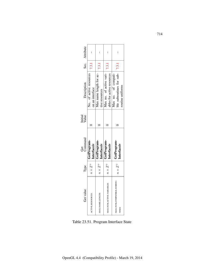
714
Get
valu
eTy
peG
etC
omm
and
Initi
alV
alue
Des
crip
tion
Sec.
Attr
ibut
e
AC
TIV
ER
ESO
UR
CE
Sn×Z
+G
etPr
ogra
m-
Inte
rfac
eiv
0N
o.of
activ
ere
sour
ces
onan
inte
rfac
e7.
3.1
–
MA
XN
AM
EL
EN
GT
Hn×Z
+G
etPr
ogra
m-
Inte
rfac
eiv
0M
axna
me
leng
thfo
rac
-tiv
ere
sour
ces
7.3.
1–
MA
XN
UM
AC
TIV
EVA
RIA
BL
ES
n×Z
+G
etPr
ogra
m-
Inte
rfac
eiv
0M
axno
.of
activ
eva
ri-
able
sfo
ract
ive
reso
urce
s7.
3.1
–
MA
XN
UM
CO
MPA
TIB
LE
SUB
RO
U-
TIN
ES
n×Z
+G
etPr
ogra
m-
Inte
rfac
eiv
0M
axno
.of
com
pati-
ble
subr
outin
esfo
rsu
b-ro
utin
eun
ifor
ms
7.3.
1–
Table 23.51. Program Interface State
OpenGL 4.4 (Compatibility Profile) - March 19, 2014
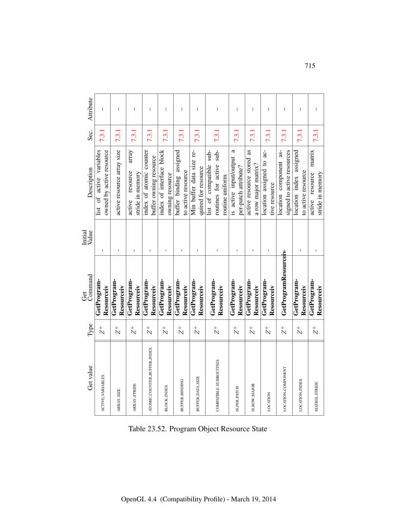
715
Get
valu
eTy
peG
etC
omm
and
Initi
alV
alue
Des
crip
tion
Sec.
Attr
ibut
e
AC
TIV
EVA
RIA
BL
ES
Z+
Get
Prog
ram
-R
esou
rcei
v-
list
ofac
tive
vari
able
sow
ned
byac
tive
reso
urce
7.3.
1–
AR
RA
YSI
ZE
Z+
Get
Prog
ram
-R
esou
rcei
v-
activ
ere
sour
cear
ray
size
7.3.
1–
AR
RA
YST
RID
EZ
+G
etPr
ogra
m-
Res
ourc
eiv
-ac
tive
reso
urce
arra
yst
ride
inm
emor
y7.
3.1
–
ATO
MIC
CO
UN
TE
RB
UFF
ER
IND
EX
Z+
Get
Prog
ram
-R
esou
rcei
v-
inde
xof
atom
icco
unte
rbu
ffer
owni
ngre
sour
ce7.
3.1
–
BL
OC
KIN
DE
XZ
+G
etPr
ogra
m-
Res
ourc
eiv
-in
dex
ofin
terf
ace
bloc
kow
ning
reso
urce
7.3.
1–
BU
FFE
RB
IND
ING
Z+
Get
Prog
ram
-R
esou
rcei
v-
buff
erbi
ndin
gas
sign
edto
activ
ere
sour
ce7.
3.1
–
BU
FFE
RD
ATA
SIZ
EZ
+G
etPr
ogra
m-
Res
ourc
eiv
-M
inbu
ffer
data
size
re-
quir
edfo
rres
ourc
e7.
3.1
–
CO
MPA
TIB
LE
SUB
RO
UT
INE
SZ
+G
etPr
ogra
m-
Res
ourc
eiv
-lis
tof
com
patib
lesu
b-ro
utin
esfo
rac
tive
sub-
rout
ine
unif
orm
7.3.
1–
ISPE
RPA
TC
HZ
+G
etPr
ogra
m-
Res
ourc
eiv
-is
activ
ein
put/o
utpu
ta
per-
patc
hat
trib
ute?
7.3.
1–
ISR
OW
MA
JOR
Z+
Get
Prog
ram
-R
esou
rcei
v-
activ
ere
sour
cest
ored
asa
row
maj
orm
atri
x?7.
3.1
–
LO
CA
TIO
NZ
+G
etPr
ogra
m-
Res
ourc
eiv
-lo
catio
nas
sign
edto
ac-
tive
reso
urce
7.3.
1–
LO
CA
TIO
NC
OM
PON
EN
TZ
+G
etPr
ogra
mR
esou
rcei
v-lo
catio
nco
mpo
nent
as-
sign
edto
activ
ere
sour
ces
7.3.
1–
LO
CA
TIO
NIN
DE
XZ
+G
etPr
ogra
m-
Res
ourc
eiv
-lo
catio
nin
dex
assi
gned
toac
tive
reso
urce
7.3.
1–
MA
TR
IXST
RID
EZ
+G
etPr
ogra
m-
Res
ourc
eiv
-ac
tive
reso
urce
mat
rix
stri
dein
mem
ory
7.3.
1–
Table 23.52. Program Object Resource State
OpenGL 4.4 (Compatibility Profile) - March 19, 2014
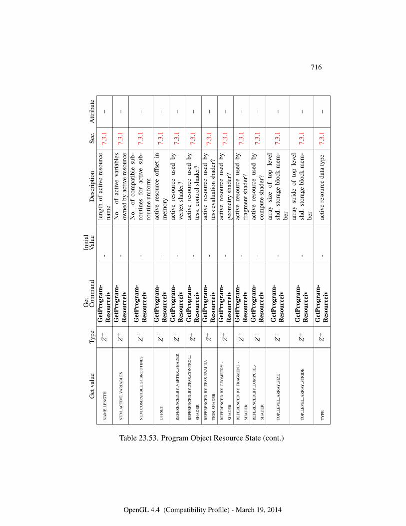
716
Get
valu
eTy
peG
etC
omm
and
Initi
alV
alue
Des
crip
tion
Sec.
Attr
ibut
e
NA
ME
LE
NG
TH
Z+
Get
Prog
ram
-R
esou
rcei
v-
leng
thof
activ
ere
sour
cena
me
7.3.
1–
NU
MA
CT
IVE
VAR
IAB
LE
SZ
+G
etPr
ogra
m-
Res
ourc
eiv
-N
o.of
activ
eva
riab
les
owne
dby
activ
ere
sour
ce7.
3.1
–
NU
MC
OM
PAT
IBL
ESU
BR
OU
TIN
ES
Z+
Get
Prog
ram
-R
esou
rcei
v-
No.
ofco
mpa
tible
sub-
rout
ines
for
activ
esu
b-ro
utin
eun
ifor
m7.
3.1
–
OFF
SET
Z+
Get
Prog
ram
-R
esou
rcei
v-
activ
ere
sour
ceof
fset
inm
emor
y7.
3.1
–
RE
FER
EN
CE
DB
YV
ER
TE
XSH
AD
ER
Z+
Get
Prog
ram
-R
esou
rcei
v-
activ
ere
sour
ceus
edby
vert
exsh
ader
?7.
3.1
–
RE
FER
EN
CE
DB
YT
ESS
CO
NT
RO
L-
SHA
DE
RZ
+G
etPr
ogra
m-
Res
ourc
eiv
-ac
tive
reso
urce
used
byte
ss.c
ontr
olsh
ader
?7.
3.1
–
RE
FER
EN
CE
DB
YT
ESS
EVA
LU
A-
TIO
NSH
AD
ER
Z+
Get
Prog
ram
-R
esou
rcei
v-
activ
ere
sour
ceus
edby
tess
eval
uatio
nsh
ader
?7.
3.1
–
RE
FER
EN
CE
DB
YG
EO
ME
TRY
-
SHA
DE
RZ
+G
etPr
ogra
m-
Res
ourc
eiv
-ac
tive
reso
urce
used
byge
omet
rysh
ader
?7.
3.1
–
RE
FER
EN
CE
DB
YFR
AG
ME
NT
-
SHA
DE
RZ
+G
etPr
ogra
m-
Res
ourc
eiv
-ac
tive
reso
urce
used
byfr
agm
ents
hade
r?7.
3.1
–
RE
FER
EN
CE
DB
YC
OM
PUT
E-
SHA
DE
RZ
+G
etPr
ogra
m-
Res
ourc
eiv
-ac
tive
reso
urce
used
byco
mpu
tesh
ader
?7.
3.1
–
TOP
LE
VE
LA
RR
AY
SIZ
EZ
+G
etPr
ogra
m-
Res
ourc
eiv
-ar
ray
size
ofto
ple
vel
shd.
stor
age
bloc
km
em-
ber
7.3.
1–
TOP
LE
VE
LA
RR
AY
STR
IDE
Z+
Get
Prog
ram
-R
esou
rcei
v-
arra
yst
ride
ofto
ple
vel
shd.
stor
age
bloc
km
em-
ber
7.3.
1–
TY
PEZ
+G
etPr
ogra
m-
Res
ourc
eiv
-ac
tive
reso
urce
data
type
7.3.
1–
Table 23.53. Program Object Resource State (cont.)
OpenGL 4.4 (Compatibility Profile) - March 19, 2014
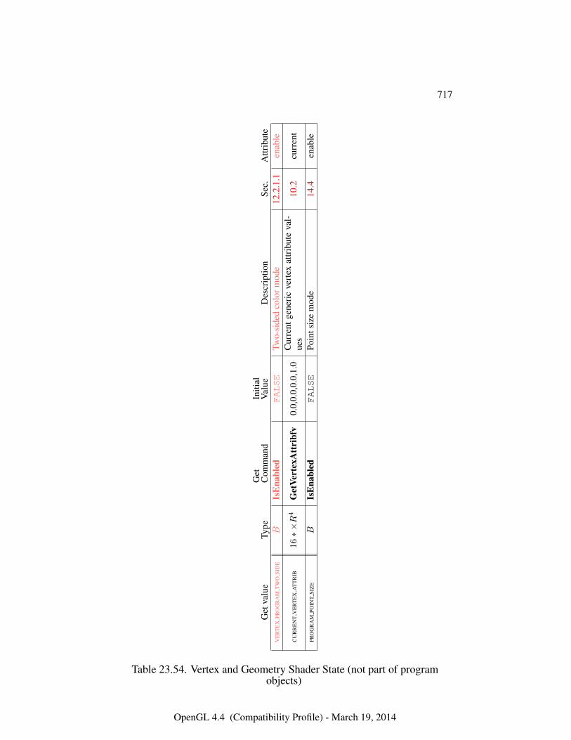
717
Get
valu
eTy
peG
etC
omm
and
Initi
alV
alue
Des
crip
tion
Sec.
Attr
ibut
eV
ER
TE
XPR
OG
RA
MT
WO
SID
EB
IsE
nabl
edFALSE
Two-
side
dco
lorm
ode
12.2
.1.1
enab
le
CU
RR
EN
TV
ER
TE
XA
TT
RIB
16∗×R
4G
etVe
rtex
Att
ribf
v0.
0,0.
0,0.
0,1.
0C
urre
ntge
neri
cve
rtex
attr
ibut
eva
l-ue
s10
.2cu
rren
t
PRO
GR
AM
POIN
TSI
ZE
BIs
Ena
bled
FALSE
Poin
tsiz
em
ode
14.4
enab
le
Table 23.54. Vertex and Geometry Shader State (not part of programobjects)
OpenGL 4.4 (Compatibility Profile) - March 19, 2014
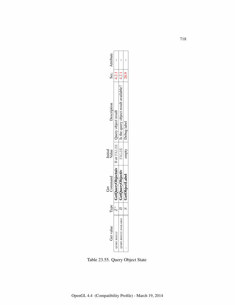
718
Get
valu
eTy
peG
etC
omm
and
Initi
alV
alue
Des
crip
tion
Sec.
Attr
ibut
eQ
UE
RYR
ESU
LTZ
+G
etQ
uery
Obj
ectu
iv0
orFALSE
Que
ryob
ject
resu
lt4.
2.1
–Q
UE
RYR
ESU
LTAV
AIL
AB
LE
BG
etQ
uery
Obj
ectiv
FALSE
Isth
equ
ery
obje
ctre
sult
avai
labl
e?4.
2.1
––
SG
etO
bjec
tLab
elem
pty
Deb
ugla
bel
20.9
–
Table 23.55. Query Object State
OpenGL 4.4 (Compatibility Profile) - March 19, 2014
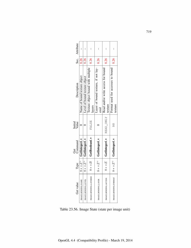
719
Get
valu
eTy
peG
etC
omm
and
Initi
alV
alue
Des
crip
tion
Sec.
Attr
ibut
eIM
AG
EB
IND
ING
NA
ME
8∗×Z
+G
etIn
tege
riv
0N
ame
ofbo
und
text
ure
obje
ct8.
26–
IMA
GE
BIN
DIN
GL
EV
EL
8∗×Z
+G
etIn
tege
riv
0L
evel
ofbo
und
text
ure
obje
ct8.
26–
IMA
GE
BIN
DIN
GL
AY
ER
ED
8∗×B
Get
Boo
lean
ivFALSE
Text
ure
obje
ctbo
und
with
mul
tiple
laye
rs8.
26–
IMA
GE
BIN
DIN
GL
AY
ER
8∗×Z
+G
etIn
tege
riv
0L
ayer
ofbo
und
text
ure,
ifno
tla
y-er
ed8.
26–
IMA
GE
BIN
DIN
GA
CC
ESS
8∗×E
Get
Inte
geri
vREAD_ONLY
Rea
dan
d/or
wri
teac
cess
for
boun
dte
xtur
e8.
26–
IMA
GE
BIN
DIN
GFO
RM
AT
8∗×Z
+G
etIn
tege
riv
R8
Form
atus
edfo
rac
cess
esto
boun
dte
xtur
e8.
26–
Table 23.56. Image State (state per image unit)
OpenGL 4.4 (Compatibility Profile) - March 19, 2014
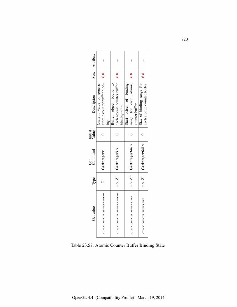
720
Get
valu
eTy
peG
etC
omm
and
Initi
alV
alue
Des
crip
tion
Sec.
Attr
ibut
e
ATO
MIC
CO
UN
TE
RB
UFF
ER
BIN
DIN
GZ
+G
etIn
tege
rv0
Cur
rent
valu
eof
gene
ric
atom
icco
unte
rbuf
ferb
ind-
ing
6.8
–
ATO
MIC
CO
UN
TE
RB
UFF
ER
BIN
DIN
Gn×Z
+G
etIn
tege
riv
0B
uffe
rob
ject
boun
dto
each
atom
icco
unte
rbu
ffer
bind
ing
poin
t6.
8–
ATO
MIC
CO
UN
TE
RB
UFF
ER
STA
RT
n×Z
+G
etIn
tege
r64i
v0
Star
tof
fset
ofbi
ndin
gra
nge
for
each
atom
icco
unte
rbuf
fer
6.8
–
ATO
MIC
CO
UN
TE
RB
UFF
ER
SIZ
En×Z
+G
etIn
tege
r64i
v0
Size
ofbi
ndin
gra
nge
for
each
atom
icco
unte
rbuf
fer
6.8
–
Table 23.57. Atomic Counter Buffer Binding State
OpenGL 4.4 (Compatibility Profile) - March 19, 2014
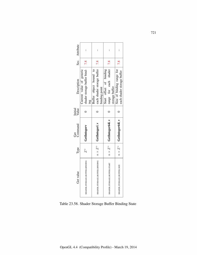
721
Get
valu
eTy
peG
etC
omm
and
Initi
alV
alue
Des
crip
tion
Sec.
Attr
ibut
e
SHA
DE
RST
OR
AG
EB
UFF
ER
BIN
DIN
GZ
+G
etIn
tege
rv0
Cur
rent
valu
eof
gene
ric
shad
erst
orag
ebu
ffer
bind
-in
g7.
8–
SHA
DE
RST
OR
AG
EB
UFF
ER
BIN
DIN
Gn×Z
+G
etIn
tege
riv
0B
uffe
rob
ject
boun
dto
each
shad
erst
orag
ebu
ffer
bind
ing
poin
t7.
8–
SHA
DE
RST
OR
AG
EB
UFF
ER
STA
RT
n×Z
+G
etIn
tege
r64i
v0
Star
tof
fset
ofbi
ndin
gra
nge
for
each
shad
erst
orag
ebu
ffer
7.8
–
SHA
DE
RST
OR
AG
EB
UFF
ER
SIZ
En×Z
+G
etIn
tege
r64i
v0
Size
ofbi
ndin
gra
nge
for
each
shad
erst
orag
ebu
ffer
7.8
–
Table 23.58. Shader Storage Buffer Binding State
OpenGL 4.4 (Compatibility Profile) - March 19, 2014
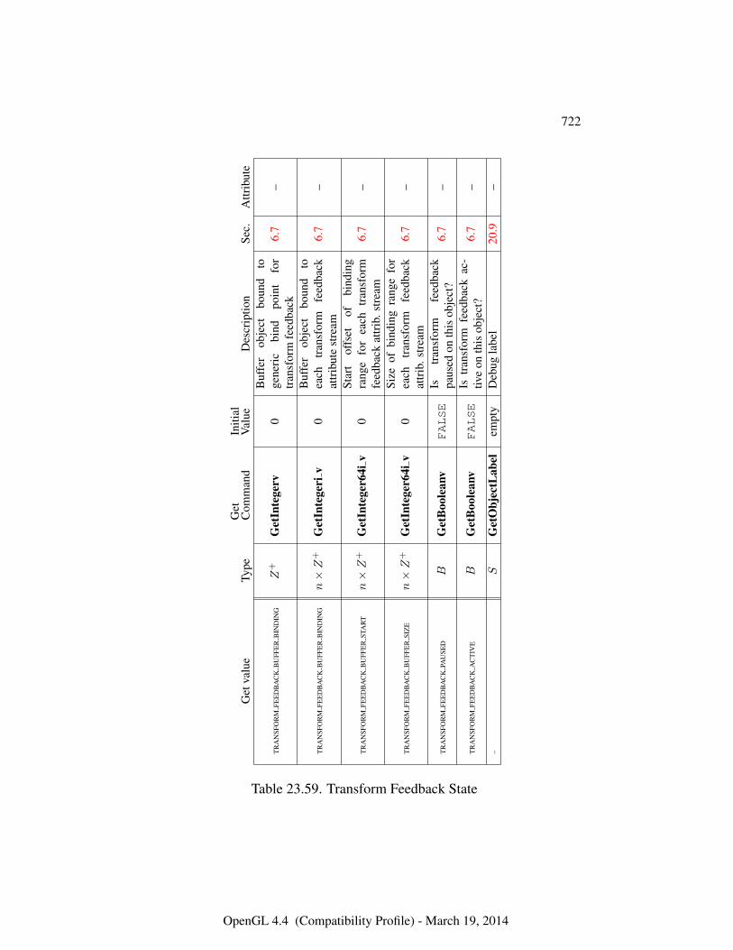
722
Get
valu
eTy
peG
etC
omm
and
Initi
alV
alue
Des
crip
tion
Sec.
Attr
ibut
e
TR
AN
SFO
RM
FEE
DB
AC
KB
UFF
ER
BIN
DIN
GZ
+G
etIn
tege
rv0
Buf
fer
obje
ctbo
und
toge
neri
cbi
ndpo
int
for
tran
sfor
mfe
edba
ck6.
7–
TR
AN
SFO
RM
FEE
DB
AC
KB
UFF
ER
BIN
DIN
Gn×Z
+G
etIn
tege
riv
0B
uffe
rob
ject
boun
dto
each
tran
sfor
mfe
edba
ckat
trib
ute
stre
am6.
7–
TR
AN
SFO
RM
FEE
DB
AC
KB
UFF
ER
STA
RT
n×Z
+G
etIn
tege
r64i
v0
Star
tof
fset
ofbi
ndin
gra
nge
for
each
tran
sfor
mfe
edba
ckat
trib
.str
eam
6.7
–
TR
AN
SFO
RM
FEE
DB
AC
KB
UFF
ER
SIZ
En×Z
+G
etIn
tege
r64i
v0
Size
ofbi
ndin
gra
nge
for
each
tran
sfor
mfe
edba
ckat
trib
.str
eam
6.7
–
TR
AN
SFO
RM
FEE
DB
AC
KPA
USE
DB
Get
Boo
lean
vFALSE
Istr
ansf
orm
feed
back
paus
edon
this
obje
ct?
6.7
–
TR
AN
SFO
RM
FEE
DB
AC
KA
CT
IVE
BG
etB
oole
anv
FALSE
Istr
ansf
orm
feed
back
ac-
tive
onth
isob
ject
?6.
7–
–S
Get
Obj
ectL
abel
empt
yD
ebug
labe
l20
.9–
Table 23.59. Transform Feedback State
OpenGL 4.4 (Compatibility Profile) - March 19, 2014
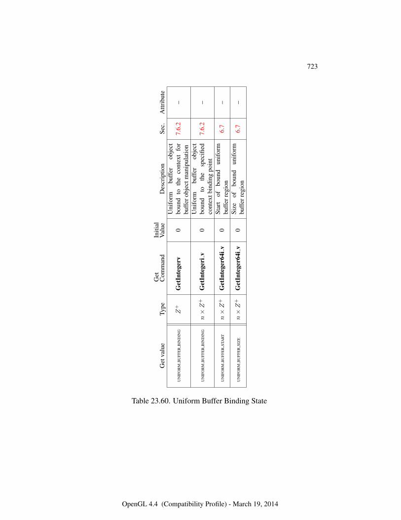
723
Get
valu
eTy
peG
etC
omm
and
Initi
alV
alue
Des
crip
tion
Sec.
Attr
ibut
e
UN
IFO
RM
BU
FFE
RB
IND
ING
Z+
Get
Inte
gerv
0U
nifo
rmbu
ffer
obje
ctbo
und
toth
eco
ntex
tfo
rbu
ffer
obje
ctm
anip
ulat
ion
7.6.
2–
UN
IFO
RM
BU
FFE
RB
IND
ING
n×Z
+G
etIn
tege
riv
0U
nifo
rmbu
ffer
obje
ctbo
und
toth
esp
ecifi
edco
ntex
tbin
ding
poin
t7.
6.2
–
UN
IFO
RM
BU
FFE
RST
AR
Tn×Z
+G
etIn
tege
r64i
v0
Star
tof
boun
dun
ifor
mbu
ffer
regi
on6.
7–
UN
IFO
RM
BU
FFE
RSI
ZE
n×Z
+G
etIn
tege
r64i
v0
Size
ofbo
und
unif
orm
buff
erre
gion
6.7
–
Table 23.60. Uniform Buffer Binding State
OpenGL 4.4 (Compatibility Profile) - March 19, 2014
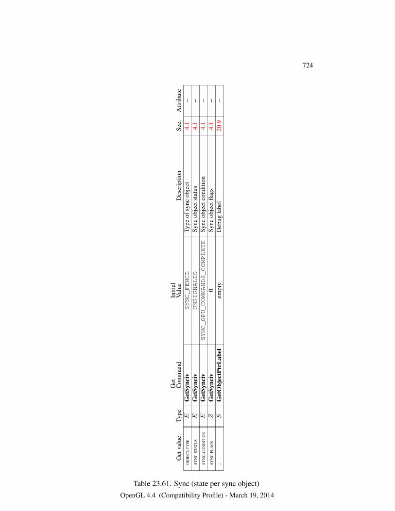
724
Get
valu
eTy
peG
etC
omm
and
Initi
alV
alue
Des
crip
tion
Sec.
Attr
ibut
eO
BJE
CT
TY
PEE
Get
Sync
ivSYNC_FENCE
Type
ofsy
ncob
ject
4.1
–SY
NC
STA
TU
SE
Get
Sync
ivUNSIGNALED
Sync
obje
ctst
atus
4.1
–SY
NC
CO
ND
ITIO
NE
Get
Sync
ivSYNC_GPU_COMMANDS_COMPLETE
Sync
obje
ctco
nditi
on4.
1–
SYN
CFL
AG
SZ
Get
Sync
iv0
Sync
obje
ctfla
gs4.
1–
–S
Get
Obj
ectP
trL
abel
empt
yD
ebug
labe
l20
.9–
Table 23.61. Sync (state per sync object)OpenGL 4.4 (Compatibility Profile) - March 19, 2014
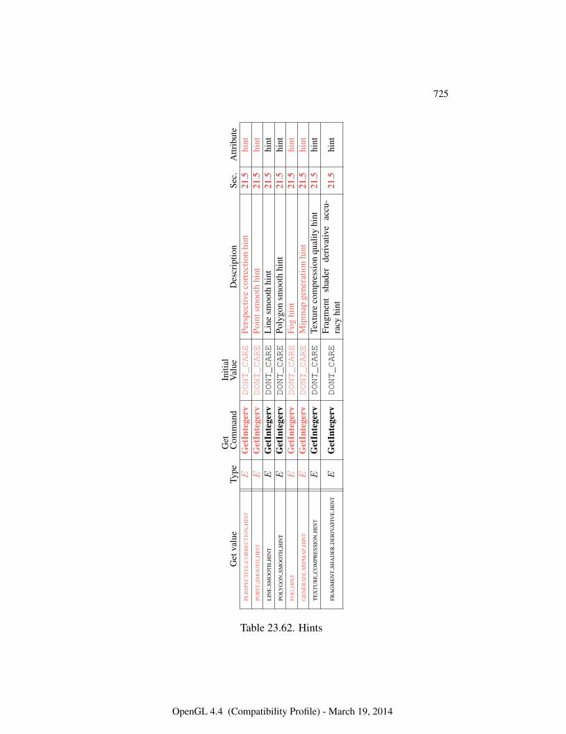
725
Get
valu
eTy
peG
etC
omm
and
Initi
alV
alue
Des
crip
tion
Sec.
Attr
ibut
ePE
RSP
EC
TIV
EC
OR
RE
CT
ION
HIN
TE
Get
Inte
gerv
DONT_CARE
Pers
pect
ive
corr
ectio
nhi
nt21
.5hi
ntPO
INT
SMO
OT
HH
INT
EG
etIn
tege
rvDONT_CARE
Poin
tsm
ooth
hint
21.5
hint
LIN
ESM
OO
TH
HIN
TE
Get
Inte
gerv
DONT_CARE
Lin
esm
ooth
hint
21.5
hint
POLY
GO
NSM
OO
TH
HIN
TE
Get
Inte
gerv
DONT_CARE
Poly
gon
smoo
thhi
nt21
.5hi
ntFO
GH
INT
EG
etIn
tege
rvDONT_CARE
Fog
hint
21.5
hint
GE
NE
RA
TE
MIP
MA
PH
INT
EG
etIn
tege
rvDONT_CARE
Mip
map
gene
ratio
nhi
nt21
.5hi
ntT
EX
TU
RE
CO
MPR
ESS
ION
HIN
TE
Get
Inte
gerv
DONT_CARE
Text
ure
com
pres
sion
qual
ityhi
nt21
.5hi
nt
FRA
GM
EN
TSH
AD
ER
DE
RIV
AT
IVE
HIN
TE
Get
Inte
gerv
DONT_CARE
Frag
men
tsh
ader
deriv
ativ
eac
cu-
racy
hint
21.5
hint
Table 23.62. Hints
OpenGL 4.4 (Compatibility Profile) - March 19, 2014
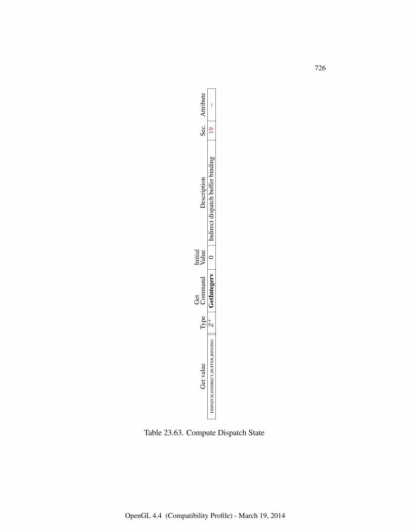
726
Get
valu
eTy
peG
etC
omm
and
Initi
alV
alue
Des
crip
tion
Sec.
Attr
ibut
eD
ISPA
TC
HIN
DIR
EC
TB
UFF
ER
BIN
DIN
GZ
+G
etIn
tege
rv0
Indi
rect
disp
atch
buff
erbi
ndin
g19
–
Table 23.63. Compute Dispatch State
OpenGL 4.4 (Compatibility Profile) - March 19, 2014
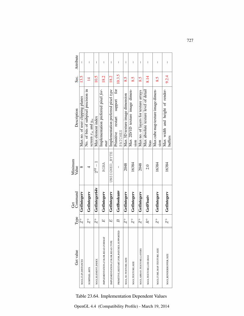
727
Get
valu
eTy
peG
etC
omm
and
Min
imum
Val
ueD
escr
iptio
nSe
c.A
ttrib
ute
MA
XC
LIP
DIS
TAN
CE
SZ
+G
etIn
tege
rv8
Max
no.o
fuse
rclip
ping
plan
es13
.5–
SUB
PIX
EL
BIT
SZ
+G
etIn
tege
rv4
No.
ofbi
tsof
subp
ixel
prec
isio
nin
scre
enxw
andy w
14–
MA
XE
LE
ME
NT
IND
EX
Z+
Get
Inte
ger6
4v23
2−
1M
axel
emen
tind
ex10
.5–
IMPL
EM
EN
TAT
ION
CO
LO
RR
EA
DFO
RM
AT
EG
etIn
tege
rvRGBA
Impl
emen
tatio
npr
efer
red
pixe
lfo
r-m
at18
.2–
IMPL
EM
EN
TAT
ION
CO
LO
RR
EA
DT
YPE
EG
etIn
tege
rvUNSIGNED_BYTE
Impl
emen
tatio
npr
efer
red
pixe
ltyp
e18
.2–
PRIM
ITIV
ER
EST
AR
TFO
RPA
TC
HE
SSU
PPO
RT
ED
BG
etB
oole
anv
–Pr
imiti
vere
star
tsu
ppor
tfo
rPATCHES
10.3
.5–
MA
X3D
TE
XT
UR
ESI
ZE
Z+
Get
Inte
gerv
2048
Max
3Dte
xtur
eim
age
dim
ensi
on8.
5–
MA
XT
EX
TU
RE
SIZ
EZ
+G
etIn
tege
rv16
384
Max
2D/1
Dte
xtur
eim
age
dim
en-
sion
8.5
–
MA
XA
RR
AY
TE
XT
UR
EL
AY
ER
SZ
+G
etIn
tege
rv20
48M
axno
.ofl
ayer
sfo
rtex
ture
arra
ys8.
5–
MA
XT
EX
TU
RE
LO
DB
IAS
R+
Get
Floa
tv2.
0M
axab
solu
tete
xtur
ele
velo
fde
tail
bias
8.14
–
MA
XC
UB
EM
AP
TE
XT
UR
ESI
ZE
Z+
Get
Inte
gerv
1638
4M
axcu
bem
apte
xtur
eim
age
dim
en-
sion
8.5
–
MA
XR
EN
DE
RB
UFF
ER
SIZ
EZ
+G
etIn
tege
rv16
384
Max
wid
than
dhe
ight
ofre
nder
-bu
ffer
s9.
2.4
–
Table 23.64. Implementation Dependent Values
OpenGL 4.4 (Compatibility Profile) - March 19, 2014
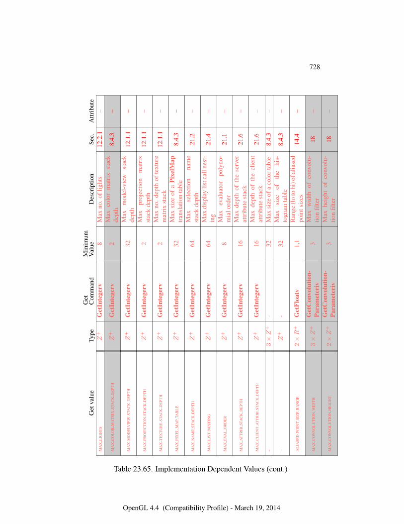
728
Get
valu
eTy
peG
etC
omm
and
Min
imum
Val
ueD
escr
iptio
nSe
c.A
ttrib
ute
MA
XL
IGH
TS
Z+
Get
Inte
gerv
8M
axno
.ofl
ight
s12
.2.1
–
MA
XC
OL
OR
MA
TR
IXST
AC
KD
EPT
HZ
+G
etIn
tege
rv2
Max
colo
rm
atri
xst
ack
dept
h8.
4.3
–
MA
XM
OD
ELV
IEW
STA
CK
DE
PTH
Z+
Get
Inte
gerv
32M
axm
odel
-vie
wst
ack
dept
h12
.1.1
–
MA
XPR
OJE
CT
ION
STA
CK
DE
PTH
Z+
Get
Inte
gerv
2M
axpr
ojec
tion
mat
rix
stac
kde
pth
12.1
.1–
MA
XT
EX
TU
RE
STA
CK
DE
PTH
Z+
Get
Inte
gerv
2M
axno
.de
pth
ofte
xtur
em
atri
xst
ack
12.1
.1–
MA
XPI
XE
LM
AP
TAB
LE
Z+
Get
Inte
gerv
32M
axsi
zeof
aPi
xelM
aptr
ansl
atio
nta
ble
8.4.
3–
MA
XN
AM
EST
AC
KD
EPT
HZ
+G
etIn
tege
rv64
Max
sele
ctio
nna
me
stac
kde
pth
21.2
–
MA
XL
IST
NE
STIN
GZ
+G
etIn
tege
rv64
Max
disp
lay
listc
alln
est-
ing
21.4
–
MA
XE
VAL
OR
DE
RZ
+G
etIn
tege
rv8
Max
eval
uato
rpo
lyno
-m
ialo
rder
21.1
–
MA
XA
TT
RIB
STA
CK
DE
PTH
Z+
Get
Inte
gerv
16M
axde
pth
ofth
ese
rver
attr
ibut
est
ack
21.6
–
MA
XC
LIE
NT
AT
TR
IBST
AC
KD
EPT
HZ
+G
etIn
tege
rv16
Max
dept
hof
the
clie
ntat
trib
ute
stac
k21
.6–
–3×Z
+-
32M
axsi
zeof
aco
lort
able
8.4.
3–
–Z
+-
32M
axsi
zeof
the
his-
togr
amta
ble
8.4.
3–
AL
IASE
DPO
INT
SIZ
ER
AN
GE
2×R
+G
etFl
oatv
1,1
Ran
ge(l
oto
hi)o
falia
sed
poin
tsiz
es14
.4–
MA
XC
ON
VO
LU
TIO
NW
IDT
H3×Z
+G
etC
onvo
lutio
n-Pa
ram
eter
iv3
Max
wid
thof
conv
olu-
tion
filte
r18
–
MA
XC
ON
VO
LU
TIO
NH
EIG
HT
2×Z
+G
etC
onvo
lutio
n-Pa
ram
eter
iv3
Max
heig
htof
conv
olu-
tion
filte
r18
–
Table 23.65. Implementation Dependent Values (cont.)
OpenGL 4.4 (Compatibility Profile) - March 19, 2014
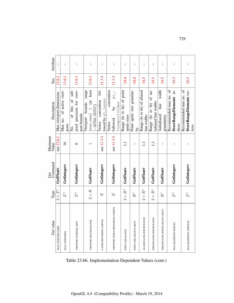
729
Get
valu
eTy
peG
etC
omm
and
Min
imum
Val
ueD
escr
iptio
nSe
c.A
ttrib
ute
MA
XV
IEW
POR
TD
IMS
2×Z
+G
etFl
oatv
see
13.6
.1M
axvi
ewpo
rtdi
men
sion
s13
.6.1
–
MA
XV
IEW
POR
TS
Z+
Get
Inte
gerv
16M
axno
.of
activ
evi
ew-
port
s13
.6.1
–
VIE
WPO
RT
SUB
PIX
EL
BIT
SZ
+G
etIn
tege
rv0
No.
ofbi
tsof
sub-
pixe
lpr
ecis
ion
for
view
-po
rtbo
unds
13.6
.1–
VIE
WPO
RT
BO
UN
DS
RA
NG
E2×R
Get
Floa
tv†
Vie
wpo
rtbo
unds
rang
e[min,m
ax
]†
(at
leas
t[−
32768,
32767])
13.6
.1–
LA
YE
RPR
OV
OK
ING
VE
RT
EX
EG
etIn
tege
rvse
e11
.3.4
Ver
tex
conv
entio
nfo
l-lo
wed
bygl_Layer
11.3
.4–
VIE
WPO
RT
IND
EX
PRO
VO
KIN
GV
ER
TE
XE
Get
Inte
gerv
see
11.3
.4V
erte
xco
nven
tion
follo
wed
bygl_-
ViewportIndex
11.3
.4–
POIN
TSI
ZE
RA
NG
E2×R
+G
etFl
oatv
1,1
Ran
ge(l
oto
hi)
ofpo
int
spri
tesi
zes
14.4
–
POIN
TSI
ZE
GR
AN
UL
AR
ITY
R+
Get
Floa
tv–
Poin
tsp
rite
size
gran
ular
-ity
14.4
–
AL
IASE
DL
INE
WID
TH
RA
NG
E2×R
+G
etFl
oatv
1,1
Ran
ge(l
oto
hi)
ofal
iase
dlin
ew
idth
s14
.5–
SMO
OT
HL
INE
WID
TH
RA
NG
E2×R
+G
etFl
oatv
1,1
Ran
ge(l
oto
hi)
ofan
-tia
liase
dlin
ew
idth
s14
.5–
SMO
OT
HL
INE
WID
TH
GR
AN
UL
AR
ITY
R+
Get
Floa
tv–
Ant
ialia
sed
line
wid
thgr
anul
arity
14.5
–
MA
XE
LE
ME
NT
SIN
DIC
ES
Z+
Get
Inte
gerv
–R
ecom
men
ded
max
no.
ofD
raw
Ran
geE
lem
ents
in-
dice
s10
.3–
MA
XE
LE
ME
NT
SV
ER
TIC
ES
Z+
Get
Inte
gerv
–R
ecom
men
ded
max
no.
ofD
raw
Ran
geE
lem
ents
ver-
tices
10.3
–
Table 23.66. Implementation Dependent Values (cont.)
OpenGL 4.4 (Compatibility Profile) - March 19, 2014
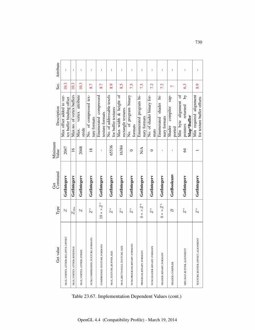
730
Get
valu
eTy
peG
etC
omm
and
Min
imum
Val
ueD
escr
iptio
nSe
c.A
ttrib
ute
MA
XV
ER
TE
XA
TT
RIB
RE
LA
TIV
EO
FFSE
TZ
Get
Inte
gerv
2047
Max
offs
etad
ded
tove
r-te
xbu
ffer
bind
ing
offs
et10
.3–
MA
XV
ER
TE
XA
TT
RIB
BIN
DIN
GS
Z16∗
Get
Inte
gerv
16M
axno
.ofv
erte
xbu
ffer
s10
.3–
MA
XV
ER
TE
XA
TT
RIB
STR
IDE
ZG
etIn
tege
rv20
48M
ax.
vert
exat
trib
ute
stri
de10
.3–
NU
MC
OM
PRE
SSE
DT
EX
TU
RE
FOR
MA
TS
Z+
Get
Inte
gerv
18N
o.of
com
pres
sed
tex-
ture
form
ats
8.7
–
CO
MPR
ESS
ED
TE
XT
UR
EFO
RM
AT
S18∗×Z
+G
etIn
tege
rv-
Enu
mer
ated
com
pres
sed
text
ure
form
ats
8.7
–
MA
XT
EX
TU
RE
BU
FFE
RSI
ZE
Z+
Get
Inte
gerv
6553
6N
o.of
addr
essa
ble
texe
lsfo
rbuf
fert
extu
res
8.9
–
MA
XR
EC
TAN
GL
ET
EX
TU
RE
SIZ
EZ
+G
etIn
tege
rv16
384
Max
wid
th&
heig
htof
rect
angl
ete
xtur
es8.
5–
NU
MPR
OG
RA
MB
INA
RYFO
RM
AT
SZ
+G
etIn
tege
rv0
No.
ofpr
ogra
mbi
nary
form
ats
7.5
–
PRO
GR
AM
BIN
ARY
FOR
MA
TS
0∗×Z
+G
etIn
tege
rvN
/AE
num
erat
edpr
ogra
mbi
-na
ryfo
rmat
s7.
5–
NU
MSH
AD
ER
BIN
ARY
FOR
MA
TS
Z+
Get
Inte
gerv
0N
o.of
shad
erbi
nary
for-
mat
s7.
2–
SHA
DE
RB
INA
RYFO
RM
AT
S0∗×Z
+G
etIn
tege
rv-
Enu
mer
ated
shad
erbi
-na
ryfo
rmat
s7.
2–
SHA
DE
RC
OM
PIL
ER
BG
etB
oole
anv
-Sh
ader
com
pile
rsu
p-po
rted
7–
MIN
MA
PB
UFF
ER
AL
IGN
ME
NT
Z+
Get
Inte
gerv
64M
inby
teal
ignm
ent
ofpo
inte
rsre
turn
edby
Map
*Buf
fer
6.3
–
TE
XT
UR
EB
UFF
ER
OFF
SET
AL
IGN
ME
NT
Z+
Get
Inte
gerv
1M
inre
quir
edal
ignm
ent
fort
extu
rebu
ffer
offs
ets
8.9
–
Table 23.67. Implementation Dependent Values (cont.)
OpenGL 4.4 (Compatibility Profile) - March 19, 2014
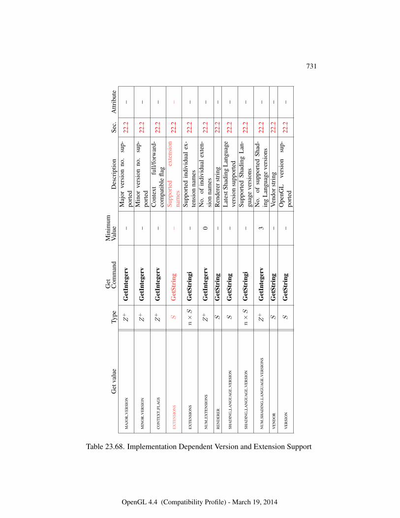
731
Get
valu
eTy
peG
etC
omm
and
Min
imum
Val
ueD
escr
iptio
nSe
c.A
ttrib
ute
MA
JOR
VE
RSI
ON
Z+
Get
Inte
gerv
–M
ajor
vers
ion
no.
sup-
port
ed22
.2–
MIN
OR
VE
RSI
ON
Z+
Get
Inte
gerv
–M
inor
vers
ion
no.
sup-
port
ed22
.2–
CO
NT
EX
TFL
AG
SZ
+G
etIn
tege
rv–
Con
text
full/
forw
ard-
com
patib
lefla
g22
.2–
EX
TE
NSI
ON
SS
Get
Stri
ng–
Supp
orte
dex
tens
ion
nam
es22
.2–
EX
TE
NSI
ON
Sn×S
Get
Stri
ngi
–Su
ppor
ted
indi
vidu
alex
-te
nsio
nna
mes
22.2
–
NU
ME
XT
EN
SIO
NS
Z+
Get
Inte
gerv
0N
o.of
indi
vidu
alex
ten-
sion
nam
es22
.2–
RE
ND
ER
ER
SG
etSt
ring
–R
ende
rers
trin
g22
.2–
SHA
DIN
GL
AN
GU
AG
EV
ER
SIO
NS
Get
Stri
ng–
Lat
estS
hadi
ngL
angu
age
vers
ion
supp
orte
d22
.2–
SHA
DIN
GL
AN
GU
AG
EV
ER
SIO
Nn×S
Get
Stri
ngi
–Su
ppor
ted
Shad
ing
Lan
-gu
age
vers
ions
22.2
–
NU
MSH
AD
ING
LA
NG
UA
GE
VE
RSI
ON
SZ
+G
etIn
tege
rv3
No.
ofsu
ppor
ted
Shad
-in
gL
angu
age
vers
ions
22.2
–
VE
ND
OR
SG
etSt
ring
–V
endo
rstr
ing
22.2
–
VE
RSI
ON
SG
etSt
ring
–O
penG
Lve
rsio
nsu
p-po
rted
22.2
–
Table 23.68. Implementation Dependent Version and Extension Support
OpenGL 4.4 (Compatibility Profile) - March 19, 2014
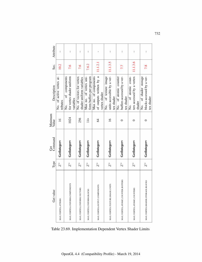
732
Get
valu
eTy
peG
etC
omm
and
Min
imum
Val
ueD
escr
iptio
nSe
c.A
ttrib
ute
MA
XV
ER
TE
XA
TT
RIB
SZ
+G
etIn
tege
rv16
No.
ofac
tive
vert
exat
-tr
ibut
es10
.2–
MA
XV
ER
TE
XU
NIF
OR
MC
OM
PON
EN
TS
Z+
Get
Inte
gerv
1024
No.
ofco
mpo
nent
sfo
rver
tex
shad
erun
ifor
mva
riab
les
7.6
–
MA
XV
ER
TE
XU
NIF
OR
MV
EC
TOR
SZ
+G
etIn
tege
rv25
6N
o.of
vect
ors
for
vert
exsh
ader
unif
orm
vari
able
s7.
6–
MA
XV
ER
TE
XU
NIF
OR
MB
LO
CK
SZ
+G
etIn
tege
rv14∗
Max
no.
ofve
rtex
uni-
form
buff
ers
perp
rogr
am7.
6.2
–
MA
XV
ER
TE
XO
UT
PUT
CO
MPO
NE
NT
SZ
+G
etIn
tege
rv64
Max
no.
ofco
mpo
nent
sof
outp
uts
wri
tten
bya
vert
exsh
ader
11.1
.2.1
-
MA
XV
ER
TE
XT
EX
TU
RE
IMA
GE
UN
ITS
Z+
Get
Inte
gerv
16N
o.of
text
ure
imag
eun
itsac
cess
ible
bya
ver-
tex
shad
er11
.1.3
.5–
MA
XV
ER
TE
XA
TOM
ICC
OU
NT
ER
BU
FFE
RS
Z+
Get
Inte
gerv
0N
o.of
atom
icco
unte
rbu
ffer
sacc
esse
dby
ave
r-te
xsh
ader
7.7
–
MA
XV
ER
TE
XA
TOM
ICC
OU
NT
ER
SZ
+G
etIn
tege
rv0
No.
ofat
omic
coun
-te
rsac
cess
edby
ave
rtex
shad
er11
.1.3
.6–
MA
XV
ER
TE
XSH
AD
ER
STO
RA
GE
BL
OC
KS
Z+
Get
Inte
gerv
0N
o.of
shad
erst
orag
ebl
ocks
acce
ssed
bya
ver-
tex
shad
er7.
8–
Table 23.69. Implementation Dependent Vertex Shader Limits
OpenGL 4.4 (Compatibility Profile) - March 19, 2014
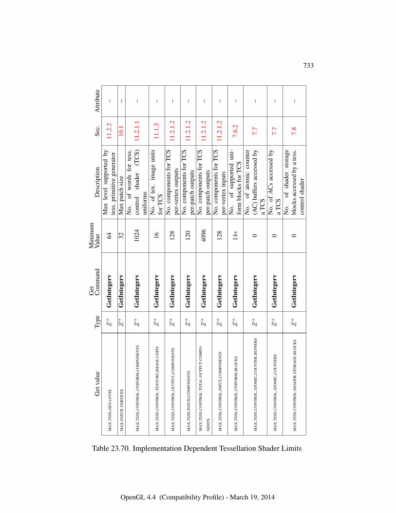
733
Get
valu
eTy
peG
etC
omm
and
Min
imum
Val
ueD
escr
iptio
nSe
c.A
ttrib
ute
MA
XT
ESS
GE
NL
EV
EL
Z+
Get
Inte
gerv
64M
axle
vel
supp
orte
dby
tess
.pri
miti
vege
nera
tor
11.2
.2–
MA
XPA
TC
HV
ER
TIC
ES
Z+
Get
Inte
gerv
32M
axpa
tch
size
10.1
–
MA
XT
ESS
CO
NT
RO
LU
NIF
OR
MC
OM
PON
EN
TS
Z+
Get
Inte
gerv
1024
No.
ofw
ords
for
tess
.co
ntro
lsh
ader
(TC
S)un
ifor
ms
11.2
.1.1
–
MA
XT
ESS
CO
NT
RO
LT
EX
TU
RE
IMA
GE
UN
ITS
Z+
Get
Inte
gerv
16N
o.of
tex.
imag
eun
itsfo
rTC
S11
.1.3
–
MA
XT
ESS
CO
NT
RO
LO
UT
PUT
CO
MPO
NE
NT
SZ
+G
etIn
tege
rv12
8N
o.co
mpo
nent
sfo
rTC
Spe
r-ve
rtex
outp
uts
11.2
.1.2
–
MA
XT
ESS
PAT
CH
CO
MPO
NE
NT
SZ
+G
etIn
tege
rv12
0N
o.co
mpo
nent
sfo
rTC
Spe
r-pa
tch
outp
uts
11.2
.1.2
–
MA
XT
ESS
CO
NT
RO
LTO
TAL
OU
TPU
TC
OM
PO-
NE
NT
SZ
+G
etIn
tege
rv40
96N
o.co
mpo
nent
sfo
rTC
Spe
r-pa
tch
outp
uts
11.2
.1.2
–
MA
XT
ESS
CO
NT
RO
LIN
PUT
CO
MPO
NE
NT
SZ
+G
etIn
tege
rv12
8N
o.co
mpo
nent
sfo
rTC
Spe
r-ve
rtex
inpu
ts11
.2.1
.2–
MA
XT
ESS
CO
NT
RO
LU
NIF
OR
MB
LO
CK
SZ
+G
etIn
tege
rv14∗
No.
ofsu
ppor
ted
uni-
form
bloc
ksfo
rTC
S7.
6.2
–
MA
XT
ESS
CO
NT
RO
LA
TOM
ICC
OU
NT
ER
BU
FFE
RS
Z+
Get
Inte
gerv
0N
o.of
atom
icco
unte
r(A
C)
buff
ers
acce
ssed
bya
TC
S7.
7–
MA
XT
ESS
CO
NT
RO
LA
TOM
ICC
OU
NT
ER
SZ
+G
etIn
tege
rv0
No.
ofA
Cs
acce
ssed
bya
TC
S7.
7–
MA
XT
ESS
CO
NT
RO
LSH
AD
ER
STO
RA
GE
BL
OC
KS
Z+
Get
Inte
gerv
0N
o.of
shad
erst
orag
ebl
ocks
acce
ssed
bya
tess
.co
ntro
lsha
der
7.8
–
Table 23.70. Implementation Dependent Tessellation Shader Limits
OpenGL 4.4 (Compatibility Profile) - March 19, 2014
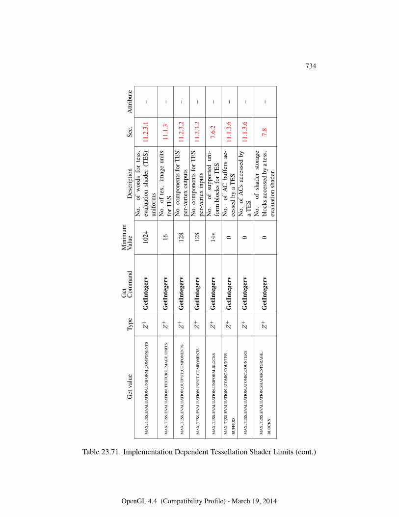
734
Get
valu
eTy
peG
etC
omm
and
Min
imum
Val
ueD
escr
iptio
nSe
c.A
ttrib
ute
MA
XT
ESS
EVA
LU
AT
ION
UN
IFO
RM
CO
MPO
NE
NT
SZ
+G
etIn
tege
rv10
24N
o.of
wor
dsfo
rte
ss.
eval
uatio
nsh
ader
(TE
S)un
ifor
ms
11.2
.3.1
–
MA
XT
ESS
EVA
LU
AT
ION
TE
XT
UR
EIM
AG
EU
NIT
SZ
+G
etIn
tege
rv16
No.
ofte
x.im
age
units
forT
ES
11.1
.3–
MA
XT
ESS
EVA
LU
AT
ION
OU
TPU
TC
OM
PON
EN
TS
Z+
Get
Inte
gerv
128
No.
com
pone
nts
forT
ES
per-
vert
exou
tput
s11
.2.3
.2–
MA
XT
ESS
EVA
LU
AT
ION
INPU
TC
OM
PON
EN
TS
Z+
Get
Inte
gerv
128
No.
com
pone
nts
forT
ES
per-
vert
exin
puts
11.2
.3.2
–
MA
XT
ESS
EVA
LU
AT
ION
UN
IFO
RM
BL
OC
KS
Z+
Get
Inte
gerv
14∗
No.
ofsu
ppor
ted
uni-
form
bloc
ksfo
rTE
S7.
6.2
–
MA
XT
ESS
EVA
LU
AT
ION
ATO
MIC
CO
UN
TE
R-
BU
FFE
RS
Z+
Get
Inte
gerv
0N
o.of
AC
buff
ers
ac-
cess
edby
aT
ES
11.1
.3.6
–
MA
XT
ESS
EVA
LU
AT
ION
ATO
MIC
CO
UN
TE
RS
Z+
Get
Inte
gerv
0N
o.of
AC
sac
cess
edby
aT
ES
11.1
.3.6
–
MA
XT
ESS
EVA
LU
AT
ION
SHA
DE
RST
OR
AG
E-
BL
OC
KS
Z+
Get
Inte
gerv
0N
o.of
shad
erst
orag
ebl
ocks
acce
ssed
bya
tess
.ev
alua
tion
shad
er7.
8–
Table 23.71. Implementation Dependent Tessellation Shader Limits (cont.)
OpenGL 4.4 (Compatibility Profile) - March 19, 2014
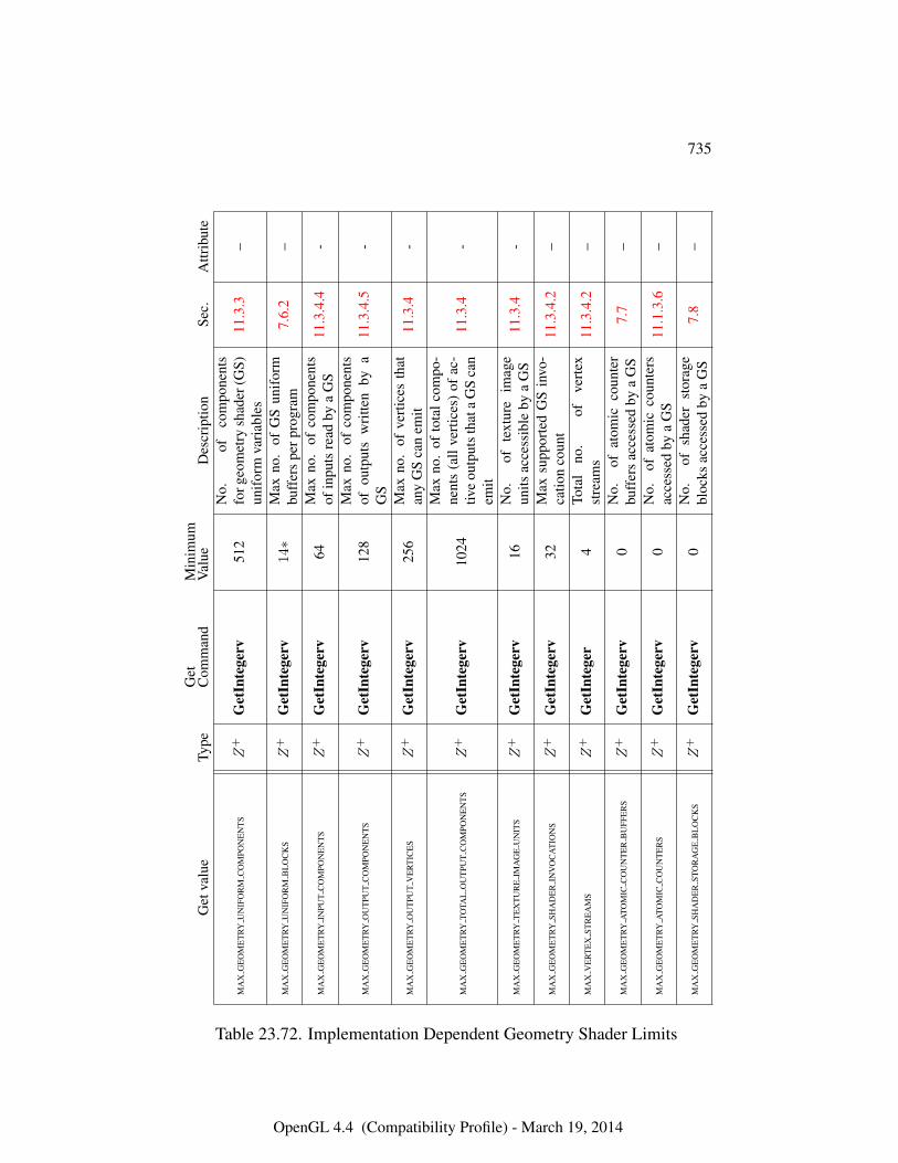
735
Get
valu
eTy
peG
etC
omm
and
Min
imum
Val
ueD
escr
iptio
nSe
c.A
ttrib
ute
MA
XG
EO
ME
TRY
UN
IFO
RM
CO
MPO
NE
NT
SZ
+G
etIn
tege
rv51
2N
o.of
com
pone
nts
forg
eom
etry
shad
er(G
S)un
ifor
mva
riab
les
11.3
.3–
MA
XG
EO
ME
TRY
UN
IFO
RM
BL
OC
KS
Z+
Get
Inte
gerv
14∗
Max
no.
ofG
Sun
ifor
mbu
ffer
spe
rpro
gram
7.6.
2–
MA
XG
EO
ME
TRY
INPU
TC
OM
PON
EN
TS
Z+
Get
Inte
gerv
64M
axno
.of
com
pone
nts
ofin
puts
read
bya
GS
11.3
.4.4
-
MA
XG
EO
ME
TRY
OU
TPU
TC
OM
PON
EN
TS
Z+
Get
Inte
gerv
128
Max
no.
ofco
mpo
nent
sof
outp
uts
wri
tten
bya
GS
11.3
.4.5
-
MA
XG
EO
ME
TRY
OU
TPU
TV
ER
TIC
ES
Z+
Get
Inte
gerv
256
Max
no.
ofve
rtic
esth
atan
yG
Sca
nem
it11
.3.4
-
MA
XG
EO
ME
TRY
TOTA
LO
UT
PUT
CO
MPO
NE
NT
SZ
+G
etIn
tege
rv10
24
Max
no.
ofto
talc
ompo
-ne
nts
(all
vert
ices
)of
ac-
tive
outp
uts
that
aG
Sca
nem
it
11.3
.4-
MA
XG
EO
ME
TRY
TE
XT
UR
EIM
AG
EU
NIT
SZ
+G
etIn
tege
rv16
No.
ofte
xtur
eim
age
units
acce
ssib
leby
aG
S11
.3.4
-
MA
XG
EO
ME
TRY
SHA
DE
RIN
VO
CA
TIO
NS
Z+
Get
Inte
gerv
32M
axsu
ppor
ted
GS
invo
-ca
tion
coun
t11
.3.4
.2–
MA
XV
ER
TE
XST
RE
AM
SZ
+G
etIn
tege
r4
Tota
lno
.of
vert
exst
ream
s11
.3.4
.2–
MA
XG
EO
ME
TRY
ATO
MIC
CO
UN
TE
RB
UFF
ER
SZ
+G
etIn
tege
rv0
No.
ofat
omic
coun
ter
buff
ers
acce
ssed
bya
GS
7.7
–
MA
XG
EO
ME
TRY
ATO
MIC
CO
UN
TE
RS
Z+
Get
Inte
gerv
0N
o.of
atom
icco
unte
rsac
cess
edby
aG
S11
.1.3
.6–
MA
XG
EO
ME
TRY
SHA
DE
RST
OR
AG
EB
LO
CK
SZ
+G
etIn
tege
rv0
No.
ofsh
ader
stor
age
bloc
ksac
cess
edby
aG
S7.
8–
Table 23.72. Implementation Dependent Geometry Shader Limits
OpenGL 4.4 (Compatibility Profile) - March 19, 2014
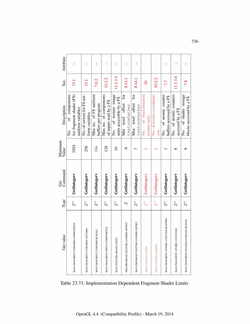
736
Get
valu
eTy
peG
etC
omm
and
Min
imum
Val
ueD
escr
iptio
nSe
c.A
ttrib
ute
MA
XFR
AG
ME
NT
UN
IFO
RM
CO
MPO
NE
NT
SZ
+G
etIn
tege
rv10
24N
o.of
com
pone
nts
for
frag
men
tsha
der
(FS)
unif
orm
vari
able
s15
.1–
MA
XFR
AG
ME
NT
UN
IFO
RM
VE
CTO
RS
Z+
Get
Inte
gerv
256
No.
ofve
ctor
sfor
FSun
i-fo
rmva
riab
les
15.1
–
MA
XFR
AG
ME
NT
UN
IFO
RM
BL
OC
KS
Z+
Get
Inte
gerv
14∗
Max
no.
ofFS
unif
orm
buff
ers
perp
rogr
am7.
6.2
–
MA
XFR
AG
ME
NT
INPU
TC
OM
PON
EN
TS
Z+
Get
Inte
gerv
128
Max
no.
ofco
mpo
nent
sof
inpu
tsre
adby
aFS
15.2
.2-
MA
XT
EX
TU
RE
IMA
GE
UN
ITS
Z+
Get
Inte
gerv
16N
o.of
text
ure
imag
eun
itsac
cess
ible
bya
FS11
.1.3
.5–
MIN
PRO
GR
AM
TE
XT
UR
EG
AT
HE
RO
FFSE
TZ
Get
Inte
gerv
-8M
inte
xel
offs
etfo
rtextureGather
8.14
.1–
MA
XPR
OG
RA
MT
EX
TU
RE
GA
TH
ER
OFF
SET
Z+
Get
Inte
gerv
7M
axte
xel
offs
etfo
rtextureGather
8.14
.1–
MA
XT
EX
TU
RE
UN
ITS
Z+
Get
Inte
gerv
2N
o.of
fixed
-fun
ctio
nte
xtur
eun
its10
–
MA
XT
EX
TU
RE
CO
OR
DS
Z+
Get
Inte
gerv
8N
o.of
text
ure
coor
dina
tese
ts10
.2.2
–
MA
XFR
AG
ME
NT
ATO
MIC
CO
UN
TE
RB
UFF
ER
SZ
+G
etIn
tege
rv1
No.
ofat
omic
coun
ter
buff
ers
acce
ssed
bya
FS7.
7–
MA
XFR
AG
ME
NT
ATO
MIC
CO
UN
TE
RS
Z+
Get
Inte
gerv
8N
o.of
atom
icco
unte
rsac
cess
edby
aFS
11.1
.3.6
–
MA
XFR
AG
ME
NT
SHA
DE
RST
OR
AG
EB
LO
CK
SZ
+G
etIn
tege
rv8
No.
ofsh
ader
stor
age
bloc
ksac
cess
edby
aFS
7.8
–
Table 23.73. Implementation Dependent Fragment Shader Limits
OpenGL 4.4 (Compatibility Profile) - March 19, 2014
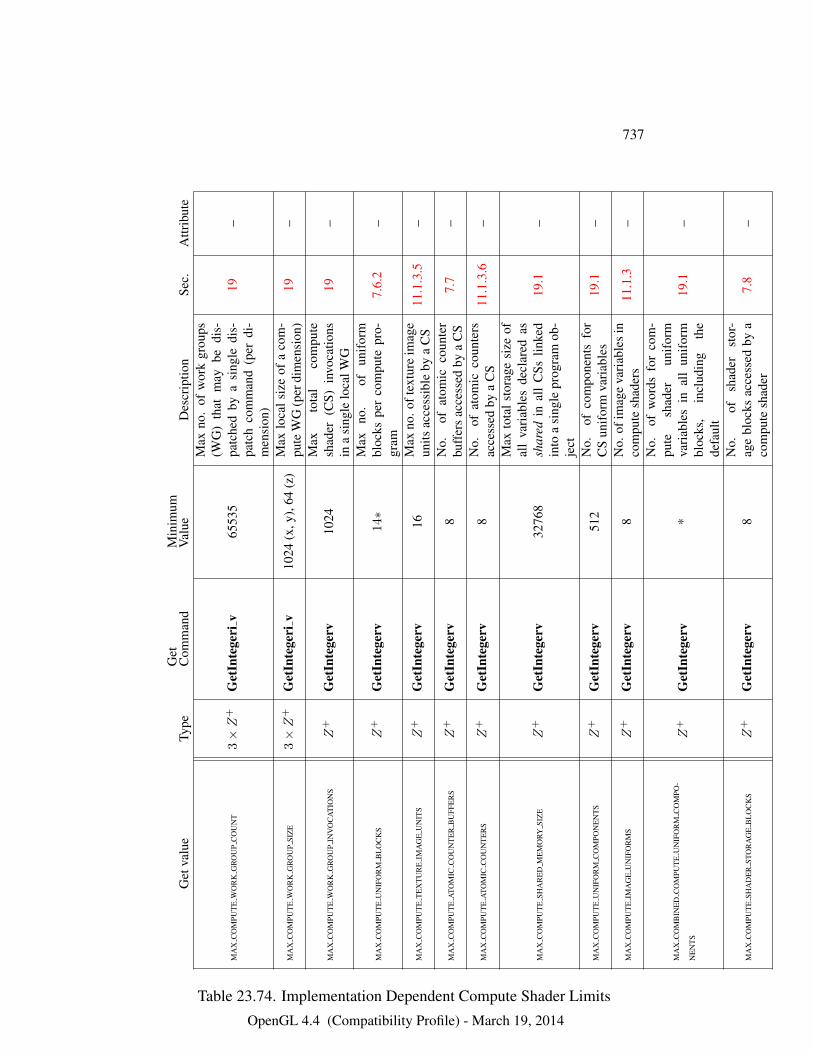
737
Get
valu
eTy
peG
etC
omm
and
Min
imum
Val
ueD
escr
iptio
nSe
c.A
ttrib
ute
MA
XC
OM
PUT
EW
OR
KG
RO
UP
CO
UN
T3×Z
+G
etIn
tege
riv
6553
5
Max
no.
ofw
ork
grou
ps(W
G)
that
may
bedi
s-pa
tche
dby
asi
ngle
dis-
patc
hco
mm
and
(per
di-
men
sion
)
19–
MA
XC
OM
PUT
EW
OR
KG
RO
UP
SIZ
E3×Z
+G
etIn
tege
riv
1024
(x,y
),64
(z)
Max
loca
lsiz
eof
aco
m-
pute
WG
(per
dim
ensi
on)
19–
MA
XC
OM
PUT
EW
OR
KG
RO
UP
INV
OC
AT
ION
SZ
+G
etIn
tege
rv10
24M
axto
tal
com
pute
shad
er(C
S)in
voca
tions
ina
sing
lelo
calW
G19
–
MA
XC
OM
PUT
EU
NIF
OR
MB
LO
CK
SZ
+G
etIn
tege
rv14∗
Max
no.
ofun
ifor
mbl
ocks
per
com
pute
pro-
gram
7.6.
2–
MA
XC
OM
PUT
ET
EX
TU
RE
IMA
GE
UN
ITS
Z+
Get
Inte
gerv
16M
axno
.oft
extu
reim
age
units
acce
ssib
leby
aC
S11
.1.3
.5–
MA
XC
OM
PUT
EA
TOM
ICC
OU
NT
ER
BU
FFE
RS
Z+
Get
Inte
gerv
8N
o.of
atom
icco
unte
rbu
ffer
sac
cess
edby
aC
S7.
7–
MA
XC
OM
PUT
EA
TOM
ICC
OU
NT
ER
SZ
+G
etIn
tege
rv8
No.
ofat
omic
coun
ters
acce
ssed
bya
CS
11.1
.3.6
–
MA
XC
OM
PUT
ESH
AR
ED
ME
MO
RYSI
ZE
Z+
Get
Inte
gerv
3276
8
Max
tota
lsto
rage
size
ofal
lva
riab
les
decl
ared
assh
ared
inal
lC
Sslin
ked
into
asi
ngle
prog
ram
ob-
ject
19.1
–
MA
XC
OM
PUT
EU
NIF
OR
MC
OM
PON
EN
TS
Z+
Get
Inte
gerv
512
No.
ofco
mpo
nent
sfo
rC
Sun
ifor
mva
riab
les
19.1
–
MA
XC
OM
PUT
EIM
AG
EU
NIF
OR
MS
Z+
Get
Inte
gerv
8N
o.of
imag
eva
riab
les
inco
mpu
tesh
ader
s11
.1.3
–
MA
XC
OM
BIN
ED
CO
MPU
TE
UN
IFO
RM
CO
MPO
-
NE
NT
SZ
+G
etIn
tege
rv*
No.
ofw
ords
for
com
-pu
tesh
ader
unif
orm
vari
able
sin
all
unif
orm
bloc
ks,
incl
udin
gth
ede
faul
t
19.1
–
MA
XC
OM
PUT
ESH
AD
ER
STO
RA
GE
BL
OC
KS
Z+
Get
Inte
gerv
8N
o.of
shad
erst
or-
age
bloc
ksac
cess
edby
aco
mpu
tesh
ader
7.8
–
Table 23.74. Implementation Dependent Compute Shader Limits
OpenGL 4.4 (Compatibility Profile) - March 19, 2014
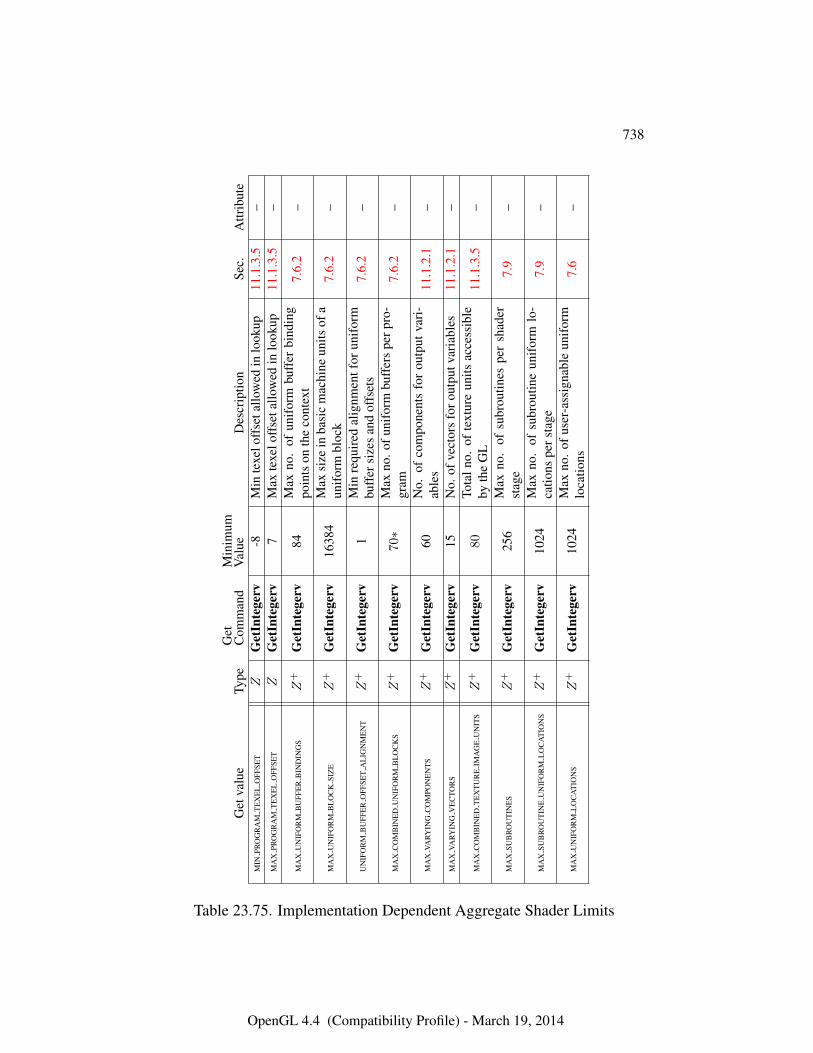
738
Get
valu
eTy
peG
etC
omm
and
Min
imum
Val
ueD
escr
iptio
nSe
c.A
ttrib
ute
MIN
PRO
GR
AM
TE
XE
LO
FFSE
TZ
Get
Inte
gerv
-8M
inte
xelo
ffse
tallo
wed
inlo
okup
11.1
.3.5
–M
AX
PRO
GR
AM
TE
XE
LO
FFSE
TZ
Get
Inte
gerv
7M
axte
xelo
ffse
tallo
wed
inlo
okup
11.1
.3.5
–
MA
XU
NIF
OR
MB
UFF
ER
BIN
DIN
GS
Z+
Get
Inte
gerv
84M
axno
.of
unif
orm
buff
erbi
ndin
gpo
ints
onth
eco
ntex
t7.
6.2
–
MA
XU
NIF
OR
MB
LO
CK
SIZ
EZ
+G
etIn
tege
rv16
384
Max
size
inba
sic
mac
hine
units
ofa
unif
orm
bloc
k7.
6.2
–
UN
IFO
RM
BU
FFE
RO
FFSE
TA
LIG
NM
EN
TZ
+G
etIn
tege
rv1
Min
requ
ired
alig
nmen
tfor
unif
orm
buff
ersi
zes
and
offs
ets
7.6.
2–
MA
XC
OM
BIN
ED
UN
IFO
RM
BL
OC
KS
Z+
Get
Inte
gerv
70∗
Max
no.o
funi
form
buff
ers
perp
ro-
gram
7.6.
2–
MA
XVA
RYIN
GC
OM
PON
EN
TS
Z+
Get
Inte
gerv
60N
o.of
com
pone
nts
for
outp
utva
ri-
able
s11
.1.2
.1–
MA
XVA
RYIN
GV
EC
TOR
SZ
+G
etIn
tege
rv15
No.
ofve
ctor
sfo
rout
putv
aria
bles
11.1
.2.1
–
MA
XC
OM
BIN
ED
TE
XT
UR
EIM
AG
EU
NIT
SZ
+G
etIn
tege
rv80
Tota
lno.
ofte
xtur
eun
itsac
cess
ible
byth
eG
L11
.1.3
.5–
MA
XSU
BR
OU
TIN
ES
Z+
Get
Inte
gerv
256
Max
no.
ofsu
brou
tines
per
shad
erst
age
7.9
–
MA
XSU
BR
OU
TIN
EU
NIF
OR
ML
OC
AT
ION
SZ
+G
etIn
tege
rv10
24M
axno
.of
subr
outin
eun
ifor
mlo
-ca
tions
pers
tage
7.9
–
MA
XU
NIF
OR
ML
OC
AT
ION
SZ
+G
etIn
tege
rv10
24M
axno
.of
user
-ass
igna
ble
unif
orm
loca
tions
7.6
–
Table 23.75. Implementation Dependent Aggregate Shader Limits
OpenGL 4.4 (Compatibility Profile) - March 19, 2014
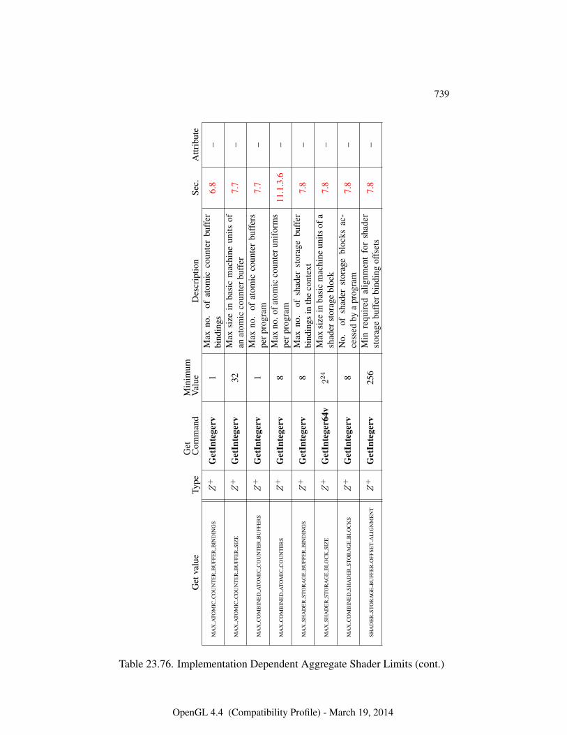
739
Get
valu
eTy
peG
etC
omm
and
Min
imum
Val
ueD
escr
iptio
nSe
c.A
ttrib
ute
MA
XA
TOM
ICC
OU
NT
ER
BU
FFE
RB
IND
ING
SZ
+G
etIn
tege
rv1
Max
no.
ofat
omic
coun
ter
buff
erbi
ndin
gs6.
8–
MA
XA
TOM
ICC
OU
NT
ER
BU
FFE
RSI
ZE
Z+
Get
Inte
gerv
32M
axsi
zein
basi
cm
achi
neun
itsof
anat
omic
coun
terb
uffe
r7.
7–
MA
XC
OM
BIN
ED
ATO
MIC
CO
UN
TE
RB
UFF
ER
SZ
+G
etIn
tege
rv1
Max
no.
ofat
omic
coun
ter
buff
ers
perp
rogr
am7.
7–
MA
XC
OM
BIN
ED
ATO
MIC
CO
UN
TE
RS
Z+
Get
Inte
gerv
8M
axno
.ofa
tom
icco
unte
runi
form
spe
rpro
gram
11.1
.3.6
–
MA
XSH
AD
ER
STO
RA
GE
BU
FFE
RB
IND
ING
SZ
+G
etIn
tege
rv8
Max
no.
ofsh
ader
stor
age
buff
erbi
ndin
gsin
the
cont
ext
7.8
–
MA
XSH
AD
ER
STO
RA
GE
BL
OC
KSI
ZE
Z+
Get
Inte
ger6
4v22
4M
axsi
zein
basi
cm
achi
neun
itsof
ash
ader
stor
age
bloc
k7.
8–
MA
XC
OM
BIN
ED
SHA
DE
RST
OR
AG
EB
LO
CK
SZ
+G
etIn
tege
rv8
No.
ofsh
ader
stor
age
bloc
ksac
-ce
ssed
bya
prog
ram
7.8
–
SHA
DE
RST
OR
AG
EB
UFF
ER
OFF
SET
AL
IGN
ME
NT
Z+
Get
Inte
gerv
256
Min
requ
ired
alig
nmen
tfo
rsh
ader
stor
age
buff
erbi
ndin
gof
fset
s7.
8–
Table 23.76. Implementation Dependent Aggregate Shader Limits (cont.)
OpenGL 4.4 (Compatibility Profile) - March 19, 2014
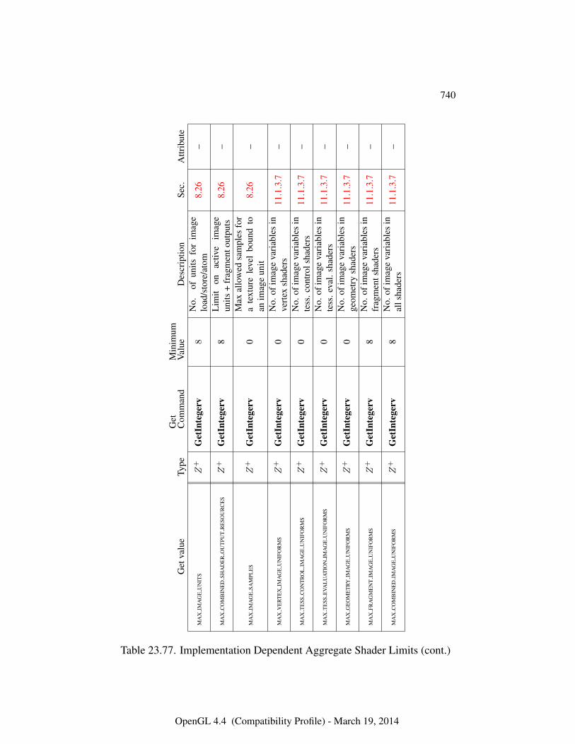
740
Get
valu
eTy
peG
etC
omm
and
Min
imum
Val
ueD
escr
iptio
nSe
c.A
ttrib
ute
MA
XIM
AG
EU
NIT
SZ
+G
etIn
tege
rv8
No.
ofun
itsfo
rim
age
load
/sto
re/a
tom
8.26
–
MA
XC
OM
BIN
ED
SHA
DE
RO
UT
PUT
RE
SOU
RC
ES
Z+
Get
Inte
gerv
8L
imit
onac
tive
imag
eun
its+
frag
men
tout
puts
8.26
–
MA
XIM
AG
ESA
MPL
ES
Z+
Get
Inte
gerv
0M
axal
low
edsa
mpl
esfo
ra
text
ure
leve
lbo
und
toan
imag
eun
it8.
26–
MA
XV
ER
TE
XIM
AG
EU
NIF
OR
MS
Z+
Get
Inte
gerv
0N
o.of
imag
eva
riab
les
inve
rtex
shad
ers
11.1
.3.7
–
MA
XT
ESS
CO
NT
RO
LIM
AG
EU
NIF
OR
MS
Z+
Get
Inte
gerv
0N
o.of
imag
eva
riab
les
inte
ss.c
ontr
olsh
ader
s11
.1.3
.7–
MA
XT
ESS
EVA
LU
AT
ION
IMA
GE
UN
IFO
RM
SZ
+G
etIn
tege
rv0
No.
ofim
age
vari
able
sin
tess
.eva
l.sh
ader
s11
.1.3
.7–
MA
XG
EO
ME
TRY
IMA
GE
UN
IFO
RM
SZ
+G
etIn
tege
rv0
No.
ofim
age
vari
able
sin
geom
etry
shad
ers
11.1
.3.7
–
MA
XFR
AG
ME
NT
IMA
GE
UN
IFO
RM
SZ
+G
etIn
tege
rv8
No.
ofim
age
vari
able
sin
frag
men
tsha
ders
11.1
.3.7
–
MA
XC
OM
BIN
ED
IMA
GE
UN
IFO
RM
SZ
+G
etIn
tege
rv8
No.
ofim
age
vari
able
sin
alls
hade
rs11
.1.3
.7–
Table 23.77. Implementation Dependent Aggregate Shader Limits (cont.)
OpenGL 4.4 (Compatibility Profile) - March 19, 2014
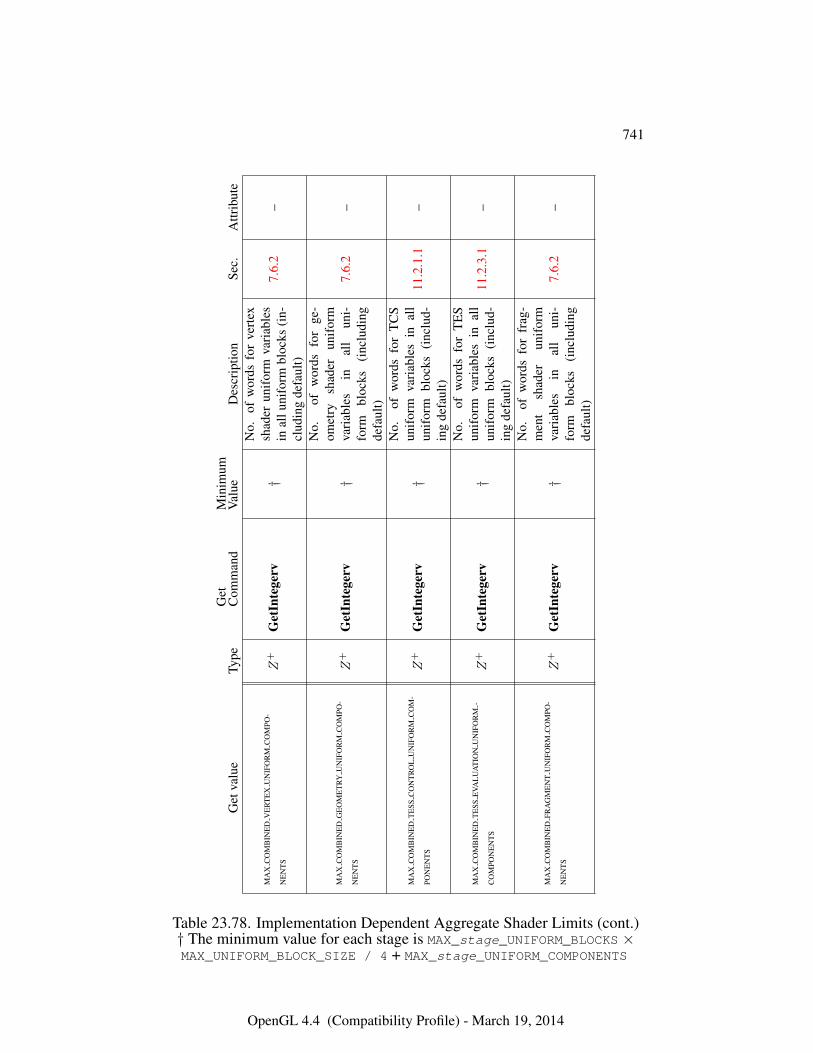
741
Get
valu
eTy
peG
etC
omm
and
Min
imum
Val
ueD
escr
iptio
nSe
c.A
ttrib
ute
MA
XC
OM
BIN
ED
VE
RT
EX
UN
IFO
RM
CO
MPO
-
NE
NT
SZ
+G
etIn
tege
rv†
No.
ofw
ords
for
vert
exsh
ader
unif
orm
vari
able
sin
allu
nifo
rmbl
ocks
(in-
clud
ing
defa
ult)
7.6.
2–
MA
XC
OM
BIN
ED
GE
OM
ET
RYU
NIF
OR
MC
OM
PO-
NE
NT
SZ
+G
etIn
tege
rv†
No.
ofw
ords
for
ge-
omet
rysh
ader
unif
orm
vari
able
sin
all
uni-
form
bloc
ks(i
nclu
ding
defa
ult)
7.6.
2–
MA
XC
OM
BIN
ED
TE
SSC
ON
TR
OL
UN
IFO
RM
CO
M-
PON
EN
TS
Z+
Get
Inte
gerv
†
No.
ofw
ords
for
TC
Sun
ifor
mva
riab
les
inal
lun
ifor
mbl
ocks
(inc
lud-
ing
defa
ult)
11.2
.1.1
–
MA
XC
OM
BIN
ED
TE
SSE
VAL
UA
TIO
NU
NIF
OR
M-
CO
MPO
NE
NT
SZ
+G
etIn
tege
rv†
No.
ofw
ords
for
TE
Sun
ifor
mva
riab
les
inal
lun
ifor
mbl
ocks
(inc
lud-
ing
defa
ult)
11.2
.3.1
–
MA
XC
OM
BIN
ED
FRA
GM
EN
TU
NIF
OR
MC
OM
PO-
NE
NT
SZ
+G
etIn
tege
rv†
No.
ofw
ords
for
frag
-m
ent
shad
erun
ifor
mva
riab
les
inal
lun
i-fo
rmbl
ocks
(inc
ludi
ngde
faul
t)
7.6.
2–
Table 23.78. Implementation Dependent Aggregate Shader Limits (cont.)† The minimum value for each stage is MAX_stage_UNIFORM_BLOCKS ×MAX_UNIFORM_BLOCK_SIZE / 4 + MAX_stage_UNIFORM_COMPONENTS
OpenGL 4.4 (Compatibility Profile) - March 19, 2014
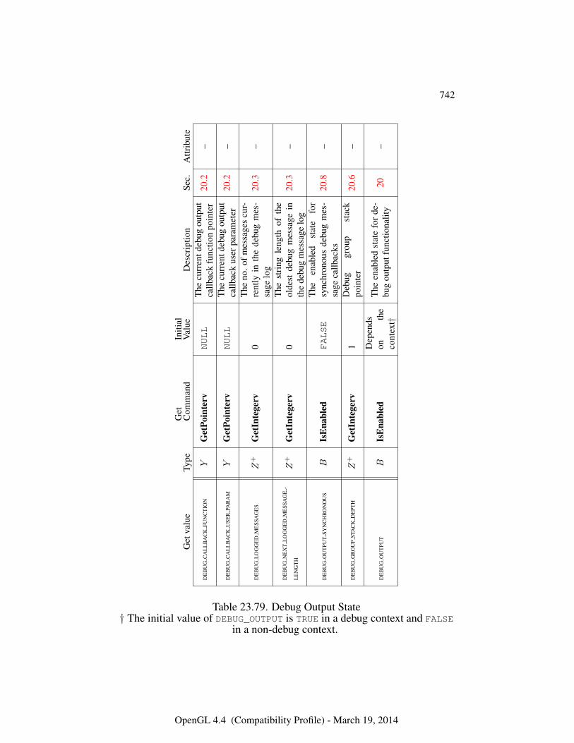
742
Get
valu
eTy
peG
etC
omm
and
Initi
alV
alue
Des
crip
tion
Sec.
Attr
ibut
e
DE
BU
GC
AL
LB
AC
KFU
NC
TIO
NY
Get
Poin
terv
NULL
The
curr
entd
ebug
outp
utca
llbac
kfu
nctio
npo
inte
r20
.2–
DE
BU
GC
AL
LB
AC
KU
SER
PAR
AM
YG
etPo
inte
rvNULL
The
curr
entd
ebug
outp
utca
llbac
kus
erpa
ram
eter
20.2
–
DE
BU
GL
OG
GE
DM
ESS
AG
ES
Z+
Get
Inte
gerv
0T
heno
.ofm
essa
ges
cur-
rent
lyin
the
debu
gm
es-
sage
log
20.3
–
DE
BU
GN
EX
TL
OG
GE
DM
ESS
AG
E-
LE
NG
TH
Z+
Get
Inte
gerv
0T
hest
ring
leng
thof
the
olde
stde
bug
mes
sage
inth
ede
bug
mes
sage
log
20.3
–
DE
BU
GO
UT
PUT
SYN
CH
RO
NO
US
BIs
Ena
bled
FALSE
The
enab
led
stat
efo
rsy
nchr
onou
sde
bug
mes
-sa
geca
llbac
ks20
.8–
DE
BU
GG
RO
UP
STA
CK
DE
PTH
Z+
Get
Inte
gerv
1D
ebug
grou
pst
ack
poin
ter
20.6
–
DE
BU
GO
UT
PUT
BIs
Ena
bled
Dep
ends
onth
eco
ntex
t†
The
enab
led
stat
efo
rde
-bu
gou
tput
func
tiona
lity
20–
Table 23.79. Debug Output State† The initial value of DEBUG_OUTPUT is TRUE in a debug context and FALSE
in a non-debug context.
OpenGL 4.4 (Compatibility Profile) - March 19, 2014
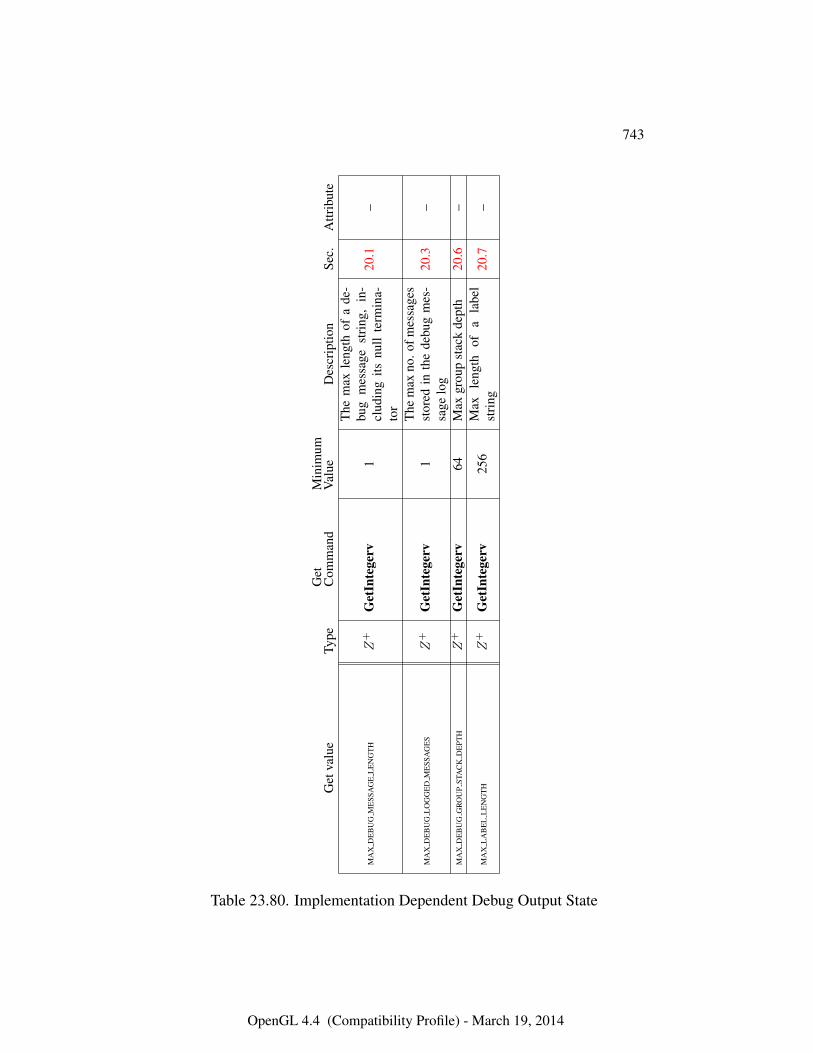
743
Get
valu
eTy
peG
etC
omm
and
Min
imum
Val
ueD
escr
iptio
nSe
c.A
ttrib
ute
MA
XD
EB
UG
ME
SSA
GE
LE
NG
TH
Z+
Get
Inte
gerv
1
The
max
leng
thof
ade
-bu
gm
essa
gest
ring
,in
-cl
udin
gits
null
term
ina-
tor
20.1
–
MA
XD
EB
UG
LO
GG
ED
ME
SSA
GE
SZ
+G
etIn
tege
rv1
The
max
no.o
fmes
sage
sst
ored
inth
ede
bug
mes
-sa
gelo
g20
.3–
MA
XD
EB
UG
GR
OU
PST
AC
KD
EPT
HZ
+G
etIn
tege
rv64
Max
grou
pst
ack
dept
h20
.6–
MA
XL
AB
EL
LE
NG
TH
Z+
Get
Inte
gerv
256
Max
leng
thof
ala
bel
stri
ng20
.7–
Table 23.80. Implementation Dependent Debug Output State
OpenGL 4.4 (Compatibility Profile) - March 19, 2014
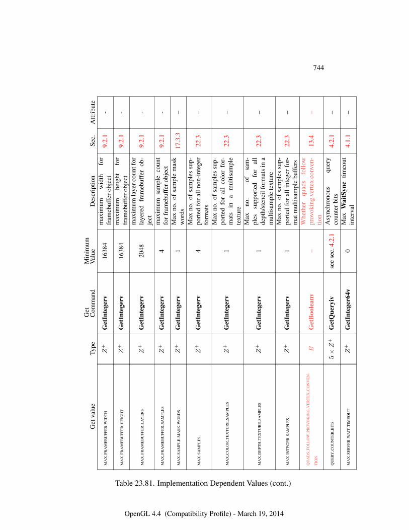
744
Get
valu
eTy
peG
etC
omm
and
Min
imum
Val
ueD
escr
iptio
nSe
c.A
ttrib
ute
MA
XFR
AM
EB
UFF
ER
WID
TH
Z+
Get
Inte
gerv
1638
4m
axim
umw
idth
for
fram
ebuf
fero
bjec
t9.
2.1
-
MA
XFR
AM
EB
UFF
ER
HE
IGH
TZ
+G
etIn
tege
rv16
384
max
imum
heig
htfo
rfr
ameb
uffe
robj
ect
9.2.
1-
MA
XFR
AM
EB
UFF
ER
LA
YE
RS
Z+
Get
Inte
gerv
2048
max
imum
laye
rcou
ntfo
rla
yere
dfr
ameb
uffe
rob
-je
ct9.
2.1
-
MA
XFR
AM
EB
UFF
ER
SAM
PLE
SZ
+G
etIn
tege
rv4
max
imum
sam
ple
coun
tfo
rfra
meb
uffe
robj
ect
9.2.
1-
MA
XSA
MPL
EM
ASK
WO
RD
SZ
+G
etIn
tege
rv1
Max
no.
ofsa
mpl
em
ask
wor
ds17
.3.3
–
MA
XSA
MPL
ES
Z+
Get
Inte
gerv
4M
axno
.of
sam
ples
sup-
port
edfo
rall
non-
inte
ger
form
ats
22.3
–
MA
XC
OL
OR
TE
XT
UR
ESA
MPL
ES
Z+
Get
Inte
gerv
1
Max
no.
ofsa
mpl
essu
p-po
rted
for
all
colo
rfo
r-m
ats
ina
mul
tisam
ple
text
ure
22.3
–
MA
XD
EPT
HT
EX
TU
RE
SAM
PLE
SZ
+G
etIn
tege
rv1
Max
no.
ofsa
m-
ples
supp
orte
dfo
ral
lde
pth/
sten
cilf
orm
ats
ina
mul
tisam
ple
text
ure
22.3
–
MA
XIN
TE
GE
RSA
MPL
ES
Z+
Get
Inte
gerv
1M
axno
.of
sam
ples
sup-
port
edfo
ral
lint
eger
for-
mat
mul
tisam
ple
buff
ers
22.3
–
QU
AD
SFO
LL
OW
PRO
VO
KIN
GV
ER
TE
XC
ON
VE
N-
TIO
NB
Get
Boo
lean
v–
Whe
ther
quad
sfo
llow
prov
okin
gve
rtex
conv
en-
tion
13.4
–
QU
ERY
CO
UN
TE
RB
ITS
5×Z
+G
etQ
uery
ivse
ese
c.4.
2.1
Asy
nchr
onou
squ
ery
coun
terb
its4.
2.1
–
MA
XSE
RVE
RW
AIT
TIM
EO
UT
Z+
Get
Inte
ger6
4v0
Max
Wai
tSyn
ctim
eout
inte
rval
4.1.
1–
Table 23.81. Implementation Dependent Values (cont.)
OpenGL 4.4 (Compatibility Profile) - March 19, 2014
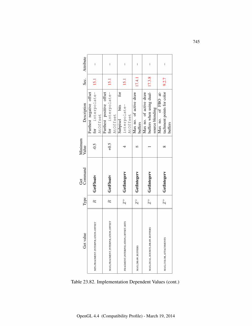
745
Get
valu
eTy
peG
etC
omm
and
Min
imum
Val
ueD
escr
iptio
nSe
c.A
ttrib
ute
MIN
FRA
GM
EN
TIN
TE
RPO
LA
TIO
NO
FFSE
TR
Get
Floa
tv-0
.5Fu
rthe
stne
gativ
eof
fset
for
interpolate-
AtOffset
15.1
–
MA
XFR
AG
ME
NT
INT
ER
POL
AT
ION
OFF
SET
RG
etFl
oatv
+0.5
Furt
hest
posi
tive
offs
etfo
rinterpolate-
AtOffset
15.1
–
FRA
GM
EN
TIN
TE
RPO
LA
TIO
NO
FFSE
TB
ITS
Z+
Get
Inte
gerv
4Su
bpix
elbi
tsfo
rinterpolate-
AtOffset
15.1
–
MA
XD
RA
WB
UFF
ER
SZ
+G
etIn
tege
rv8
Max
no.
ofac
tive
draw
buff
ers
17.4
.1–
MA
XD
UA
LSO
UR
CE
DR
AW
BU
FFE
RS
Z+
Get
Inte
gerv
1M
axno
.of
activ
edr
awbu
ffer
sw
hen
usin
gdu
al-
sour
cebl
endi
ng17
.3.8
–
MA
XC
OL
OR
AT
TAC
HM
EN
TS
Z+
Get
Inte
gerv
8M
axno
.of
FBO
at-
tach
men
tpoi
nts
forc
olor
buff
ers
9.2.
7–
Table 23.82. Implementation Dependent Values (cont.)
OpenGL 4.4 (Compatibility Profile) - March 19, 2014
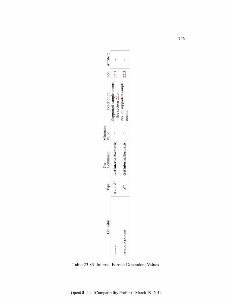
746
Get
valu
eTy
peG
etC
omm
and
Min
imum
Val
ueD
escr
iptio
nSe
c.A
ttrib
ute
SAM
PLE
S0∗×Z
+G
etIn
tern
alfo
rmat
iv†
Supp
orte
dsa
mpl
eco
unts
†Se
ese
ctio
n22
.322
.3–
NU
MSA
MPL
EC
OU
NT
SZ
+G
etIn
tern
alfo
rmat
iv1
No.
ofsu
ppor
ted
sam
ple
coun
ts22
.3–
Table 23.83. Internal Format Dependent Values
OpenGL 4.4 (Compatibility Profile) - March 19, 2014
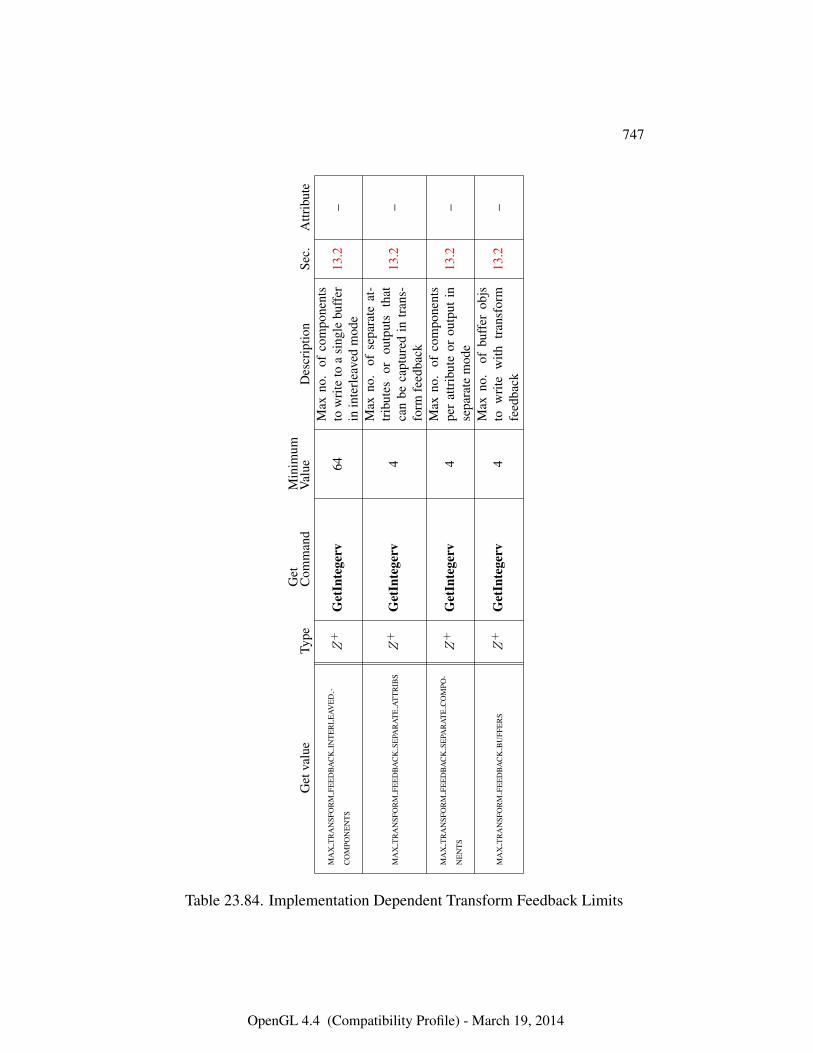
747
Get
valu
eTy
peG
etC
omm
and
Min
imum
Val
ueD
escr
iptio
nSe
c.A
ttrib
ute
MA
XT
RA
NSF
OR
MFE
ED
BA
CK
INT
ER
LE
AVE
D-
CO
MPO
NE
NT
SZ
+G
etIn
tege
rv64
Max
no.
ofco
mpo
nent
sto
wri
teto
asi
ngle
buff
erin
inte
rlea
ved
mod
e13
.2–
MA
XT
RA
NSF
OR
MFE
ED
BA
CK
SEPA
RA
TE
AT
TR
IBS
Z+
Get
Inte
gerv
4
Max
no.
ofse
para
teat
-tr
ibut
esor
outp
uts
that
can
beca
ptur
edin
tran
s-fo
rmfe
edba
ck
13.2
–
MA
XT
RA
NSF
OR
MFE
ED
BA
CK
SEPA
RA
TE
CO
MPO
-
NE
NT
SZ
+G
etIn
tege
rv4
Max
no.
ofco
mpo
nent
spe
rat
trib
ute
orou
tput
inse
para
tem
ode
13.2
–
MA
XT
RA
NSF
OR
MFE
ED
BA
CK
BU
FFE
RS
Z+
Get
Inte
gerv
4M
axno
.of
buff
erob
jsto
wri
tew
ithtr
ansf
orm
feed
back
13.2
–
Table 23.84. Implementation Dependent Transform Feedback Limits
OpenGL 4.4 (Compatibility Profile) - March 19, 2014
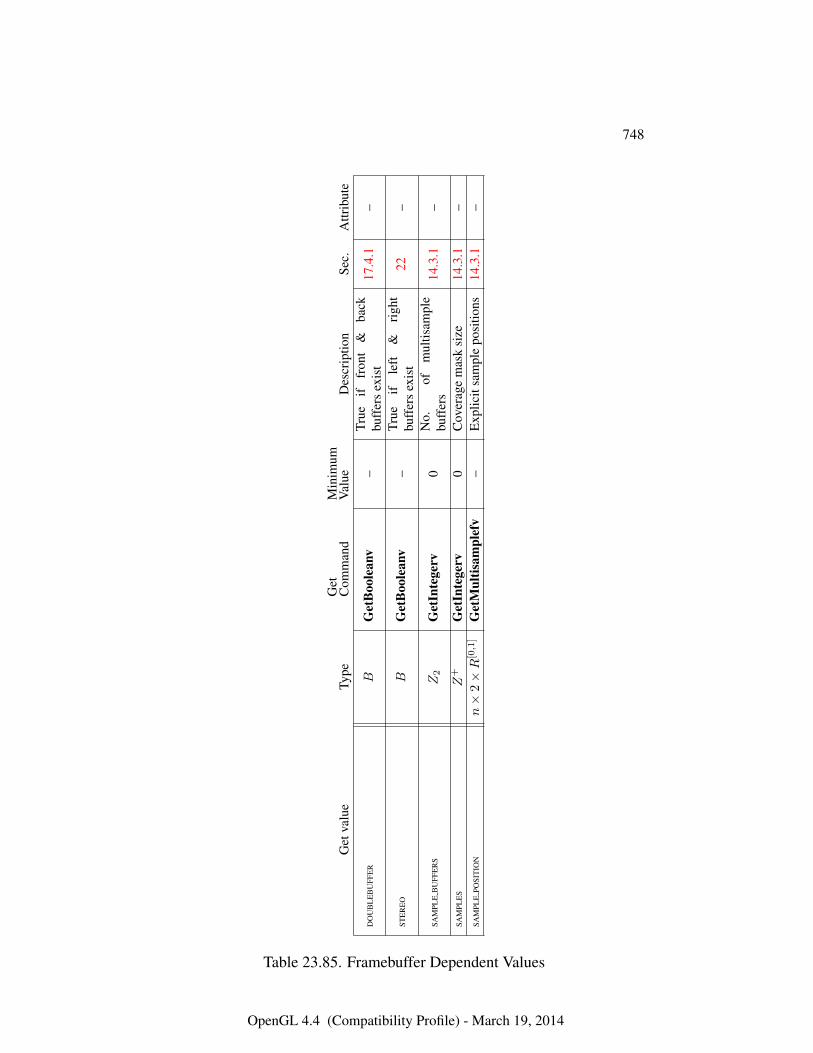
748
Get
valu
eTy
peG
etC
omm
and
Min
imum
Val
ueD
escr
iptio
nSe
c.A
ttrib
ute
DO
UB
LE
BU
FFE
RB
Get
Boo
lean
v–
True
iffr
ont
&ba
ckbu
ffer
sex
ist
17.4
.1–
STE
RE
OB
Get
Boo
lean
v–
True
ifle
ft&
righ
tbu
ffer
sex
ist
22–
SAM
PLE
BU
FFE
RS
Z2
Get
Inte
gerv
0N
o.of
mul
tisam
ple
buff
ers
14.3
.1–
SAM
PLE
SZ
+G
etIn
tege
rv0
Cov
erag
em
ask
size
14.3
.1–
SAM
PLE
POSI
TIO
Nn×
2×R
[0,1]
Get
Mul
tisam
plef
v–
Exp
licit
sam
ple
posi
tions
14.3
.1–
Table 23.85. Framebuffer Dependent Values
OpenGL 4.4 (Compatibility Profile) - March 19, 2014
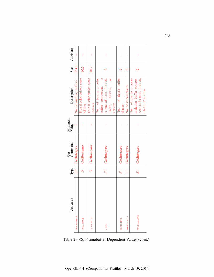
749
Get
valu
eTy
peG
etC
omm
and
Min
imum
Val
ueD
escr
iptio
nSe
c.A
ttrib
ute
AU
XB
UFF
ER
SZ
+G
etIn
tege
rv0
No.
ofau
xilia
rybu
ffer
s17
.4.1
–
RG
BA
MO
DE
BG
etB
oole
anv
–Tr
ueif
colo
rbuf
fers
stor
eR
GB
A10
.2–
IND
EX
MO
DE
BG
etB
oole
anv
–Tr
ueif
colo
rbuf
fers
stor
ein
dexe
s10
.2–
xB
ITS
Z+
Get
Inte
gerv
-
No.
ofbi
tsinx
colo
rbu
ffer
com
pone
nt.
xis
one
ofRED
,GREEN
,BLUE
,ALPHA
,or
INDEX
9–
DE
PTH
BIT
SZ
+G
etIn
tege
rv-
No.
ofde
pth
buff
erpl
anes
9–
STE
NC
ILB
ITS
Z+
Get
Inte
gerv
-N
o.of
sten
cilp
lane
s9
–
AC
CU
Mx
BIT
SZ
+G
etIn
tege
rv-
No.
ofbi
tsinx
accu
-m
ulat
ion
buff
erco
mpo
-ne
nt(x
isRED
,GREEN
,BLUE
,orALPHA
9–
Table 23.86. Framebuffer Dependent Values (cont.)
OpenGL 4.4 (Compatibility Profile) - March 19, 2014
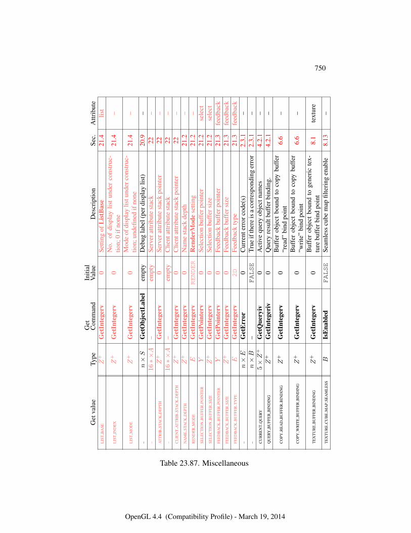
750
Get
valu
eTy
peG
etC
omm
and
Initi
alV
alue
Des
crip
tion
Sec.
Attr
ibut
eL
IST
BA
SEZ
+G
etIn
tege
rv0
Setti
ngof
Lis
tBas
e21
.4lis
t
LIS
TIN
DE
XZ
+G
etIn
tege
rv0
No.
ofdi
spla
ylis
tun
der
cons
truc
-tio
n;0
ifno
ne21
.4–
LIS
TM
OD
EZ
+G
etIn
tege
rv0
Mod
eof
disp
lay
listu
nder
cons
truc
-tio
n;un
defin
edif
none
21.4
–
–n×S
Get
Obj
ectL
abel
empt
yD
ebug
labe
l(pe
rdis
play
list)
20.9
––
16∗×A
–em
pty
Serv
erat
trib
ute
stac
k22
–A
TT
RIB
STA
CK
DE
PTH
Z+
Get
Inte
gerv
0Se
rver
attr
ibut
est
ack
poin
ter
22–
–16∗×A
–em
pty
Clie
ntat
trib
ute
stac
k22
–C
LIE
NT
AT
TR
IBST
AC
KD
EPT
HZ
+G
etIn
tege
rv0
Clie
ntat
trib
ute
stac
kpo
inte
r22
–N
AM
EST
AC
KD
EPT
HZ
+G
etIn
tege
rv0
Nam
est
ack
dept
h21
.2–
RE
ND
ER
MO
DE
EG
etIn
tege
rvRENDER
Ren
derM
ode
setti
ng21
.2–
SEL
EC
TIO
NB
UFF
ER
POIN
TE
RY
Get
Poin
terv
0Se
lect
ion
buff
erpo
inte
r21
.2se
lect
SEL
EC
TIO
NB
UFF
ER
SIZ
EZ
+G
etIn
tege
rv0
Sele
ctio
nbu
ffer
size
21.2
sele
ctFE
ED
BA
CK
BU
FFE
RPO
INT
ER
YG
etPo
inte
rv0
Feed
back
buff
erpo
inte
r21
.3fe
edba
ckFE
ED
BA
CK
BU
FFE
RSI
ZE
Z+
Get
Inte
gerv
0Fe
edba
ckbu
ffer
size
21.3
feed
back
FEE
DB
AC
KB
UFF
ER
TY
PEE
Get
Inte
gerv
2D
Feed
back
type
21.3
feed
back
–n×E
Get
Err
or0
Cur
rent
erro
rcod
e(s)
2.3.
1–
–n×B
–FALSE
True
ifth
ere
isa
corr
espo
ndin
ger
ror
2.3.
1–
CU
RR
EN
TQ
UE
RY5×Z
+G
etQ
uery
iv0
Act
ive
quer
yob
ject
nam
es4.
2.1
–Q
UE
RYB
UFF
ER
BIN
DIN
GZ
+G
etIn
tege
riv
0Q
uery
resu
ltbu
ffer
bind
ing.
4.2.
1–
CO
PYR
EA
DB
UFF
ER
BIN
DIN
GZ
+G
etIn
tege
rv0
Buf
fer
obje
ctbo
und
toco
pybu
ffer
“rea
d”bi
ndpo
int
6.6
–
CO
PYW
RIT
EB
UFF
ER
BIN
DIN
GZ
+G
etIn
tege
rv0
Buf
fer
obje
ctbo
und
toco
pybu
ffer
“wri
te”
bind
poin
t6.
6–
TE
XT
UR
EB
UFF
ER
BIN
DIN
GZ
+G
etIn
tege
rv0
Buf
fer
obje
ctbo
und
toge
neri
cte
x-tu
rebu
ffer
bind
poin
t8.
1te
xtur
e
TE
XT
UR
EC
UB
EM
AP
SEA
ML
ESS
BIs
Ena
bled
FALSE
Seam
less
cube
map
filte
ring
enab
le8.
13–
Table 23.87. Miscellaneous
OpenGL 4.4 (Compatibility Profile) - March 19, 2014
Appendix A
Invariance
The OpenGL specification is not pixel exact. It therefore does not guarantee an ex-act match between images produced by different GL implementations. However,the specification does specify exact matches, in some cases, for images producedby the same implementation. The purpose of this appendix is to identify and pro-vide justification for those cases that require exact matches.
A.1 Repeatability
The obvious and most fundamental case is repeated issuance of a series of GL com-mands. For any given GL and framebuffer state vector, and for any GL command,the resulting GL and framebuffer state must be identical whenever the command isexecuted on that initial GL and framebuffer state. This repeatability requirementdoesn’t apply when using shaders containing side effects (image and buffer vari-able stores and atomic operations, and atomic counter operations), because thesememory operations are not guaranteed to be processed in a defined order.
One purpose of repeatability is avoidance of visual artifacts when a double-buffered scene is redrawn. If rendering is not repeatable, swapping between twobuffers rendered with the same command sequence may result in visible changesin the image. Such false motion is distracting to the viewer. Another reason forrepeatability is testability.
Repeatability, while important, is a weak requirement. Given only repeata-bility as a requirement, two scenes rendered with one (small) polygon changedin position might differ at every pixel. Such a difference, while within the lawof repeatability, is certainly not within its spirit. Additional invariance rules aredesirable to ensure useful operation.
751
A.2. MULTI-PASS ALGORITHMS 752
A.2 Multi-pass Algorithms
Invariance is necessary for a whole set of useful multi-pass algorithms. Such al-gorithms render multiple times, each time with a different GL mode vector, toeventually produce a result in the framebuffer. Examples of these algorithms in-clude:
• “Erasing” a primitive from the framebuffer by redrawing it, either in a dif-ferent color or using the XOR logical operation.
• Using stencil operations to compute capping planes.
On the other hand, invariance rules can greatly increase the complexity of high-performance implementations of the GL. Even the weak repeatability requirementsignificantly constrains a parallel implementation of the GL. Because GL imple-mentations are required to implement ALL GL capabilities, not just a convenientsubset, those that utilize hardware acceleration are expected to alternate betweenhardware and software modules based on the current GL mode vector. A stronginvariance requirement forces the behavior of the hardware and software modulesto be identical, something that may be very difficult to achieve (for example, if thehardware does floating-point operations with different precision than the software).
What is desired is a compromise that results in many compliant, high-performance implementations, and in many software vendors choosing to port toOpenGL.
A.3 Invariance Rules
For a given instantiation of an OpenGL rendering context:
Rule 1 For any given GL and framebuffer state vector, and for any given GL com-mand, the resulting GL and framebuffer state must be identical each time the com-mand is executed on that initial GL and framebuffer state.
Rule 2 Changes to the following state values have no side effects (the use of anyother state value is not affected by the change):
Required:
• Framebuffer contents (all bitplanes)
• The color buffers enabled for writing
• The values of matrices other than the top-of-stack matrices
OpenGL 4.4 (Compatibility Profile) - March 19, 2014
A.3. INVARIANCE RULES 753
• Scissor parameters (other than enable)
• Writemasks (color, index, depth, stencil)
• Clear values (color, index, depth, stencil, accumulation)
◦ Current values (color, index, normal, texture coords, edgeflag)
◦ Current raster color, index and texture coordinates
◦ Material properties (ambient, diffuse, specular, emission, shininess)
Strongly suggested:
• Matrix mode
• Matrix stack depths
• Alpha test parameters (other than enable)
• Stencil parameters (other than enable)
• Depth test parameters (other than enable)
• Blend parameters (other than enable)
• Logical operation parameters (other than enable)
• Pixel storage and transfer state
• Evaluator state (except as it affects the vertex data generated by theevaluators)
• Polygon offset parameters (other than enables, and except as they affectthe depth values of fragments)
Corollary 1 Fragment generation is invariant with respect to the state valuesmarked with • in Rule 2.
Corollary 2 The window coordinates (x, y, and z) of generated fragments are alsoinvariant with respect to
Required:
• Current values (color, color index, normal, texture coords, edgeflag)
• Current raster color, color index, and texture coordinates
• Material properties (ambient, diffuse, specular, emission, shininess)
OpenGL 4.4 (Compatibility Profile) - March 19, 2014
A.3. INVARIANCE RULES 754
Rule 3 The arithmetic of each per-fragment operation is invariant except with re-spect to parameters that directly control it (the parameters that control the alphatest, for instance, are the alpha test enable, the alpha test function, and the alphatest reference value).
Corollary 3 Images rendered into different color buffers sharing the same frame-buffer, either simultaneously or separately using the same command sequence, arepixel identical.
Rule 4 The same vertex or fragment shader will produce the same result whenrun multiple times with the same input. The wording ‘the same shader’ means aprogram object that is populated with the same source strings, which are compiledand then linked, possibly multiple times, and which program object is then executedusing the same GL state vector. Invariance is relaxed for shaders with side effects,such as accessing atomic counters (see section A.5).
Rule 5 All fragment shaders that either conditionally or unconditionally assigngl_FragCoord.z to gl_FragDepth are depth-invariant with respect to eachother, for those fragments where the assignment to gl_FragDepth actually isdone.
If a sequence of GL commands specifies primitives to be rendered with shaderscontaining side effects (image and buffer variable stores and atomic operations,and atomic counter operations), invariance rules are relaxed. In particular, rule 1,corollary 3, and rule 4 do not apply in the presence of shader side effects.
The following weaker versions of rules 1 and 4 apply to GL commands involv-ing shader side effects:
Rule 6 For any given GL and framebuffer state vector, and for any given GL com-mand, the contents of any framebuffer state not directly or indirectly affected byresults of shader image or buffer variable stores or atomic operations, or atomiccounter operations must be identical each time the command is executed on thatinitial GL and framebuffer state.
Rule 7 The same vertex or fragment shader will produce the same result when runmultiple times with the same input as long as:
• shader invocations do not use image atomic operations or atomic counters;
• no framebuffer memory is written to more than once by image stores, unlessall such stores write the same value; and
OpenGL 4.4 (Compatibility Profile) - March 19, 2014
A.4. TESSELLATION INVARIANCE 755
• no shader invocation, or other operation performed to process the sequenceof commands, reads memory written to by an image store.
When any sequence of GL commands triggers shader invocations that performimage stores, atomic operations, or atomic counter operations, and subsequent GLcommands read the memory written by those shader invocations, these operationsmust be explicitly synchronized. For more details, see section 7.12.
A.4 Tessellation Invariance
When using a program containing tessellation evaluation shaders, the fixed-function tessellation primitive generator consumes the input patch specified by anapplication and emits a new set of primitives. The following invariance rules areintended to provide repeatability guarantees. Additionally, they are intended to al-low an application with a carefully crafted tessellation evaluation shader to ensurethat the sets of triangles generated for two adjacent patches have identical verticesalong shared patch edges, avoiding “cracks” caused by minor differences in thepositions of vertices along shared edges.
Rule 1 When processing two patches with identical outer and inner tessellationlevels, the tessellation primitive generator will emit an identical set of point, line,or triangle primitives as long as the active program used to process the patch prim-itives has tessellation evaluation shaders specifying the same tessellation mode,spacing, vertex order, and point mode input layout qualifiers. Two sets of primi-tives are considered identical if and only if they contain the same number and typeof primitives and the generated tessellation coordinates for the vertex numbered mof the primitive numbered n are identical for all values of m and n.
Rule 2 The set of vertices generated along the outer edge of the subdivided prim-itive in triangle and quad tessellation, and the tessellation coordinates of each,depends only on the corresponding outer tessellation level and the spacing inputlayout qualifier in the tessellation evaluation shader of the active program.
Rule 3 The set of vertices generated when subdividing any outer primitive edge isalways symmetric. For triangle tessellation, if the subdivision generates a vertexwith tessellation coordinates of the form (0, x, 1−x), (x, 0, 1−x), or (x, 1−x, 0),it will also generate a vertex with coordinates of exactly (0, 1−x, x), (1−x, 0, x),or (1 − x, x, 0), respectively. For quad tessellation, if the subdivision generatesa vertex with coordinates of (x, 0) or (0, x), it will also generate a vertex withcoordinates of exactly (1−x, 0) or (0, 1−x), respectively. For isoline tessellation,
OpenGL 4.4 (Compatibility Profile) - March 19, 2014
A.4. TESSELLATION INVARIANCE 756
if it generates vertices at (0, x) and (1, x) where x is not zero, it will also generatevertices at exactly (0, 1− x) and (1, 1− x), respectively.
Rule 4 The set of vertices generated when subdividing outer edges in triangularand quad tessellation must be independent of the specific edge subdivided, givenidentical outer tessellation levels and spacing. For example, if vertices at (x, 1 −x, 0) and (1−x, x, 0) are generated when subdividing thew = 0 edge in triangulartessellation, vertices must be generated at (x, 0, 1 − x) and (1 − x, 0, x) whensubdividing an otherwise identical v = 0 edge. For quad tessellation, if verticesat (x, 0) and (1 − x, 0) are generated when subdividing the v = 0 edge, verticesmust be generated at (0, x) and (0, 1−x) when subdividing an otherwise identicalu = 0 edge.
Rule 5 When processing two patches that are identical in all respects enumeratedin rule 1 except for vertex order, the set of triangles generated for triangle andquad tessellation must be identical except for vertex and triangle order. For eachtriangle n1 produced by processing the first patch, there must be a triangle n2produced when processing the second patch each of whose vertices has the sametessellation coordinates as one of the vertices in n1.
Rule 6 When processing two patches that are identical in all respects enumeratedin rule 1 other than matching outer tessellation levels and/or vertex order, the setof interior triangles generated for triangle and quad tessellation must be identicalin all respects except for vertex and triangle order. For each interior triangle n1produced by processing the first patch, there must be a triangle n2 produced whenprocessing the second patch each of whose vertices has the same tessellation co-ordinates as one of the vertices in n1. A triangle produced by the tessellator isconsidered an interior triangle if none of its vertices lie on an outer edge of thesubdivided primitive.
Rule 7 For quad and triangle tessellation, the set of triangles connecting an innerand outer edge depends only on the inner and outer tessellation levels correspond-ing to that edge and the spacing input layout qualifier.
Rule 8 The value of all defined components of gl_TessCoordwill be in the range[0, 1]. Additionally, for any defined component x of gl_TessCoord, the results ofcomputing 1.0−x in a tessellation evaluation shader will be exact. Some floating-point values in the range [0, 1] may fail to satisfy this property, but such values maynever be used as tessellation coordinate components.
OpenGL 4.4 (Compatibility Profile) - March 19, 2014
A.5. ATOMIC COUNTER INVARIANCE 757
A.5 Atomic Counter Invariance
When using a program containing atomic counters, the following invariance rulesare intended to provide repeatability guarantees but within certain constraints.
Rule 1 When a single shader type within a program accesses an atomic counterwith only atomicCounterIncrement, any individual shader invocation is guar-anteed to get a unique value returned.
Corollary 1 Also holds true with atomicCounterDecrement.
Corollary 2 This does not hold true for atomicCounter.
Corollary 3 Repeatability is relaxed. While a unique value is returned to theshader, even given the same initial state vector and buffer contents, it is not guar-anteed that the same unique value will be returned for each individual invocationof a shader (for example, on any single vertex, or any single fragment). It is whollythe shader writer’s responsibility to respect this constraint.
Rule 2 When two or more shader types within a program access an atomic counterwith only atomicCounterIncrement, there is no repeatability of the orderingof operations between stages. For example, some number of vertices may be pro-cessed, then some number of fragments may be processed.
Corollary 4 This also holds true with atomicCounterDecrement andatomicCounter.
A.6 What All This Means
Hardware accelerated GL implementations are expected to default to software op-eration when some GL state vectors are encountered. Even the weak repeatabilityrequirement means, for example, that OpenGL implementations cannot apply hys-teresis to this swap, but must instead guarantee that a given mode vector impliesthat a subsequent command always is executed in either the hardware or the soft-ware machine.
The stronger invariance rules constrain when the switch from hardware to soft-ware rendering can occur, given that the software and hardware renderers are notpixel identical. For example, the switch can be made when blending is enabled ordisabled, but it should not be made when a change is made to the blending param-eters.
OpenGL 4.4 (Compatibility Profile) - March 19, 2014

A.6. WHAT ALL THIS MEANS 758
Because floating-point values may be represented using different formats indifferent renderers (hardware and software), many OpenGL state values maychange subtly when renderers are swapped. This is the type of state value changethat invariance rule 1 in section A.3 seeks to avoid.
OpenGL 4.4 (Compatibility Profile) - March 19, 2014
Appendix B
Corollaries
The following observations are derived from the body and the other appendixes ofthe specification. Absence of an observation from this list in no way impugns itsveracity.
1. The CURRENT_RASTER_TEXTURE_COORDS must be maintained correctly atall times, including periods while texture mapping is not enabled, and whenthe GL is in color index mode.
2. When requested, texture coordinates returned in feedback mode are alwaysvalid, including periods while texture mapping is not enabled, and when theGL is in color index mode.
3. The error semantics of upward compatible OpenGL revisions may change,and features deprecated in a previous revision may be removed. Otherwise,only additions can be made to upward compatible revisions.
4. GL query commands are not required to satisfy the semantics of the Flushor the Finish commands. All that is required is that the queried state be con-sistent with complete execution of all previously executed GL commands.
5. Application specified point size and line width must be returned as specifiedwhen queried. Implementation-dependent clamping affects the values onlywhile they are in use.
6. Bitmaps and pixel transfers do not cause selection hits.
7. The mask specified as the third argument to StencilFunc affects the operandsof the stencil comparison function, but has no direct effect on the update ofthe stencil buffer. The mask specified by StencilMask has no effect on the
759
760
stencil comparison function; it limits the effect of the update of the stencilbuffer.
8. Polygon shading is completed before the polygon mode is interpreted. If theshade model is FLAT, all of the points or lines generated by a single polygonwill have the same color.
9. A display list is just a group of commands and arguments, so errors generatedby commands in a display list must be generated when the list is executed.If the list is created in COMPILE mode, errors should not be generated whilethe list is being created.
10. RasterPos does not change the current raster index from its default valuein an RGBA mode GL context. Likewise, RasterPos does not change thecurrent raster color from its default value in a color index GL context. Boththe current raster index and the current raster color can be queried, however,regardless of the color mode of the GL context.
11. A material property that is attached to the current color via ColorMaterialalways takes the value of the current color. Attempts to change that materialproperty via Material calls have no effect.
12. Material and ColorMaterial can be used to modify the RGBA materialproperties, even in a color index context. Likewise, Material can be used tomodify the color index material properties, even in an RGBA context.
13. There is no atomicity requirement for OpenGL rendering commands, evenat the fragment level.
14. Because rasterization of non-antialiased polygons is point sampled, poly-gons that have no area generate no fragments when they are rasterized inFILL mode, and the fragments generated by the rasterization of “narrow”polygons may not form a continuous array.
15. OpenGL does not force left- or right-handedness on any of its coordinatessystems. Consider, however, the following conditions: (1) the object coordi-nate system is right-handed; (2) the only commands used to manipulate themodel-view matrix are Scale (with positive scaling values only), Rotate, andTranslate; (3) exactly one of either Frustum or Ortho is used to set the pro-jection matrix; (4) the near value is less than the far value for DepthRange.If these conditions are all satisfied, then the eye coordinate system is right-handed and the clip, normalized device, and window coordinate systems areleft-handed.
OpenGL 4.4 (Compatibility Profile) - March 19, 2014
761
16. ColorMaterial has no effect on color index lighting.
17. (No pixel dropouts or duplicates.) Let two polygons share an identical edge.That is, there exist vertices A and B of an edge of one polygon, and verticesC and D of an edge of the other polygon; the positions of vertex A andC are identical; and the positions of vertex B and D are identical. Vertexpositions are identical for the fixed-function pipeline if they are specifiedwith the same input values and the state of coordinate transformations isidentical when the vertices are processed; otherwise they are identical if thegl_Position values output by the vertex (or if active, geometry) shaderare identical. Then, when the fragments produced by rasterization of bothpolygons are taken together, each fragment intersecting the interior of theshared edge is produced exactly once.
18. OpenGL state continues to be modified in FEEDBACK mode and in SELECT
mode. The contents of the framebuffer are not modified.
19. The current raster position, the user defined clip planes, the spot directionsand the light positions for LIGHTi, and the eye planes for texgen are trans-formed when they are specified. They are not transformed during a PopAt-trib, or when copying a context.
20. Dithering algorithms may be different for different components. In particu-lar, alpha may be dithered differently from red, green, or blue, and an imple-mentation may choose to not dither alpha at all.
21. For any GL and framebuffer state, and for any group of GL commands andarguments, the resulting GL and framebuffer state is identical whether theGL commands and arguments are executed normally or from a display list.The only exception to this corollary is for built-in shader variables gl_-
VertexID and gl_PrimitiveID, which are not defined when drawing ge-ometry within a display list.
OpenGL 4.4 (Compatibility Profile) - March 19, 2014
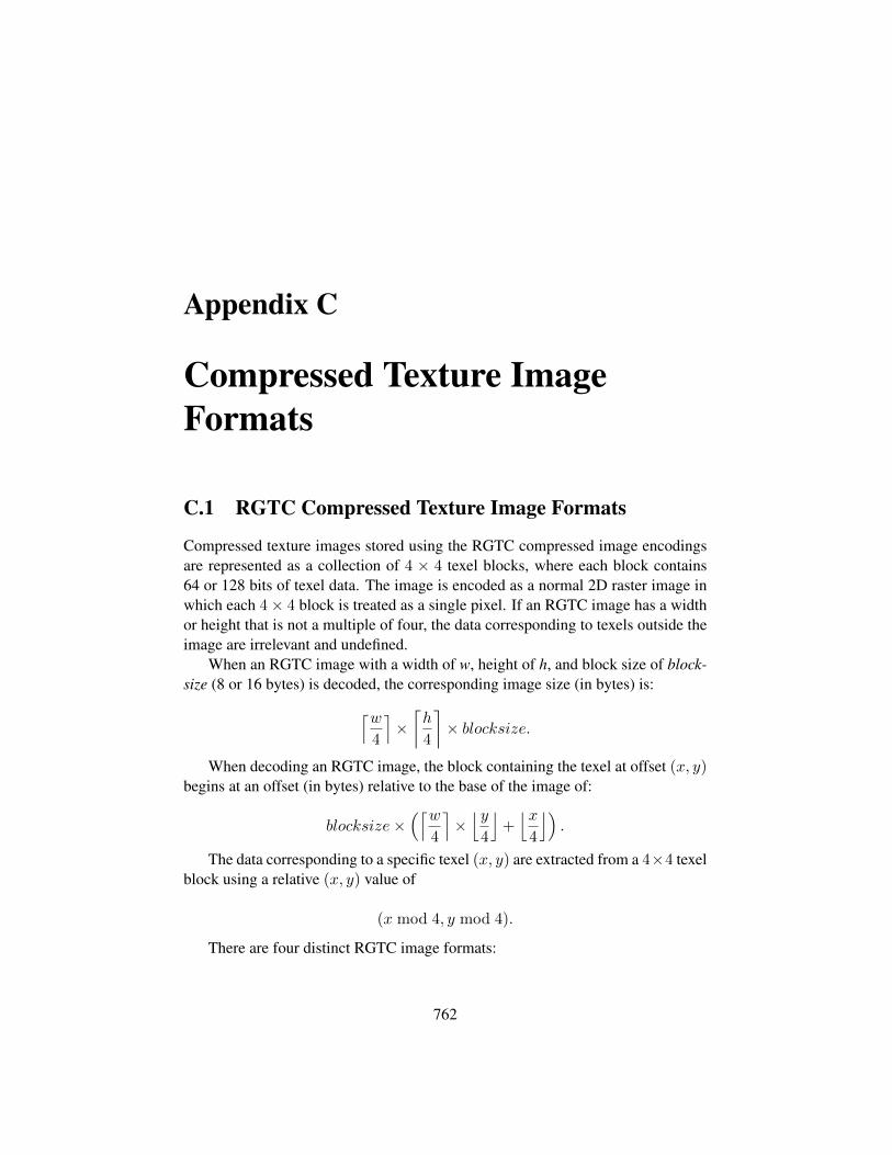
Appendix C
Compressed Texture ImageFormats
C.1 RGTC Compressed Texture Image Formats
Compressed texture images stored using the RGTC compressed image encodingsare represented as a collection of 4 × 4 texel blocks, where each block contains64 or 128 bits of texel data. The image is encoded as a normal 2D raster image inwhich each 4× 4 block is treated as a single pixel. If an RGTC image has a widthor height that is not a multiple of four, the data corresponding to texels outside theimage are irrelevant and undefined.
When an RGTC image with a width of w, height of h, and block size of block-size (8 or 16 bytes) is decoded, the corresponding image size (in bytes) is:⌈w
4
⌉×⌈h
4
⌉× blocksize.
When decoding an RGTC image, the block containing the texel at offset (x, y)begins at an offset (in bytes) relative to the base of the image of:
blocksize×(⌈w
4
⌉×⌊y
4
⌋+⌊x
4
⌋).
The data corresponding to a specific texel (x, y) are extracted from a 4×4 texelblock using a relative (x, y) value of
(x mod 4, y mod 4).
There are four distinct RGTC image formats:
762
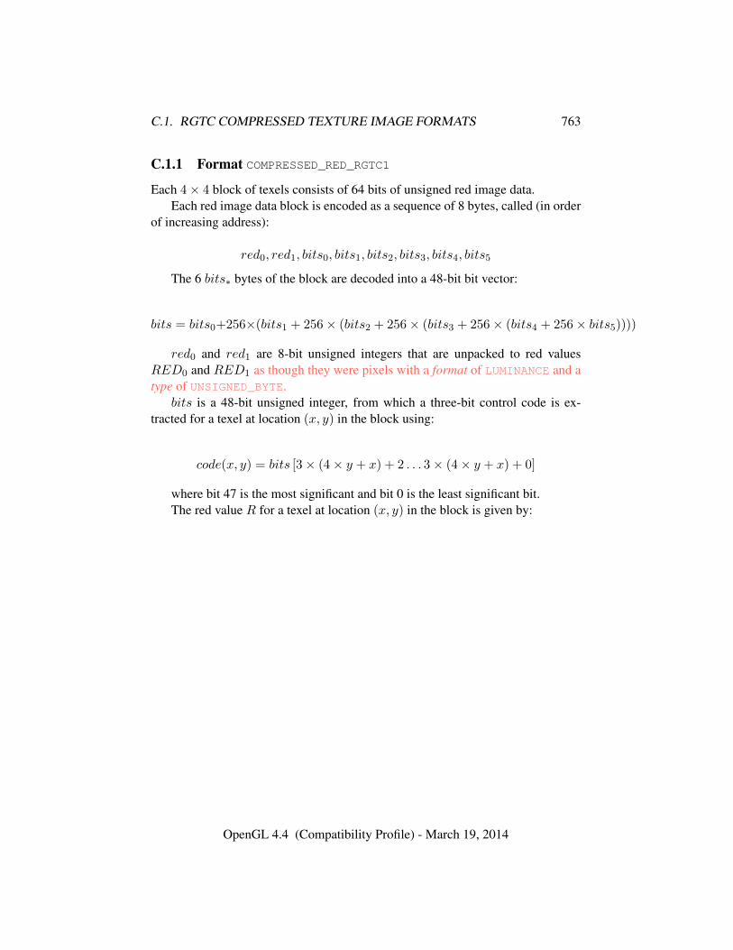
C.1. RGTC COMPRESSED TEXTURE IMAGE FORMATS 763
C.1.1 Format COMPRESSED_RED_RGTC1
Each 4× 4 block of texels consists of 64 bits of unsigned red image data.Each red image data block is encoded as a sequence of 8 bytes, called (in order
of increasing address):
red0, red1, bits0, bits1, bits2, bits3, bits4, bits5
The 6 bits∗ bytes of the block are decoded into a 48-bit bit vector:
bits = bits0+256×(bits1 + 256× (bits2 + 256× (bits3 + 256× (bits4 + 256× bits5))))
red0 and red1 are 8-bit unsigned integers that are unpacked to red valuesRED0 and RED1 as though they were pixels with a format of LUMINANCE and atype of UNSIGNED_BYTE.
bits is a 48-bit unsigned integer, from which a three-bit control code is ex-tracted for a texel at location (x, y) in the block using:
code(x, y) = bits [3× (4× y + x) + 2 . . . 3× (4× y + x) + 0]
where bit 47 is the most significant and bit 0 is the least significant bit.The red value R for a texel at location (x, y) in the block is given by:
OpenGL 4.4 (Compatibility Profile) - March 19, 2014
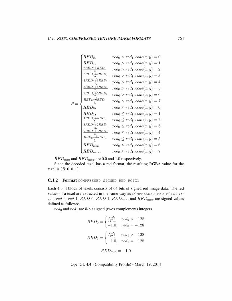
C.1. RGTC COMPRESSED TEXTURE IMAGE FORMATS 764
R =
RED0, red0 > red1, code(x, y) = 0
RED1, red0 > red1, code(x, y) = 16RED0+RED1
7, red0 > red1, code(x, y) = 25RED0+2RED1
7, red0 > red1, code(x, y) = 34RED0+3RED1
7, red0 > red1, code(x, y) = 43RED0+4RED1
7, red0 > red1, code(x, y) = 52RED0+5RED1
7, red0 > red1, code(x, y) = 6RED0+6RED1
7, red0 > red1, code(x, y) = 7
RED0, red0 ≤ red1, code(x, y) = 0
RED1, red0 ≤ red1, code(x, y) = 14RED0+RED1
5, red0 ≤ red1, code(x, y) = 23RED0+2RED1
5, red0 ≤ red1, code(x, y) = 32RED0+3RED1
5, red0 ≤ red1, code(x, y) = 4RED0+4RED1
5, red0 ≤ red1, code(x, y) = 5
REDmin, red0 ≤ red1, code(x, y) = 6
REDmax, red0 ≤ red1, code(x, y) = 7
REDmin and REDmax are 0.0 and 1.0 respectively.Since the decoded texel has a red format, the resulting RGBA value for the
texel is (R, 0, 0, 1).
C.1.2 Format COMPRESSED_SIGNED_RED_RGTC1
Each 4 × 4 block of texels consists of 64 bits of signed red image data. The redvalues of a texel are extracted in the same way as COMPRESSED_RED_RGTC1 ex-cept red 0, red 1, RED 0, RED 1, REDmin, and REDmax are signed valuesdefined as follows:
red0 and red1 are 8-bit signed (twos complement) integers.
RED0 =
{red0127.0, red0 > −128
−1.0, red0 = −128
RED1 =
{red1127.0, red1 > −128
−1.0, red1 = −128
REDmin = −1.0
OpenGL 4.4 (Compatibility Profile) - March 19, 2014
C.2. BPTC COMPRESSED TEXTURE IMAGE FORMATS 765
REDmax = 1.0
CAVEAT for signed red0 and red1 values: the expressions red0 > red1 andred0 ≤ red1 above are considered undefined (read: may vary by implementation)when red0 = −127 and red1 = −128. This is because if red0 were remapped to-127 prior to the comparison to reduce the latency of a hardware decompressor, theexpressions would reverse their logic. Encoders for the signed red-green formatsshould avoid encoding blocks where red0 = −127 and red1 = −128.
C.1.3 Format COMPRESSED_RG_RGTC2
Each 4 × 4 block of texels consists of 64 bits of compressed unsigned red imagedata followed by 64 bits of compressed unsigned green image data.
The first 64 bits of compressed red are decoded exactly like COMPRESSED_-
RED_RGTC1 above.The second 64 bits of compressed green are decoded exactly like
COMPRESSED_RED_RGTC1 above except the decoded value R for this secondblock is considered the resulting green value G.
Since the decoded texel has a red-green format, the resulting RGBA value forthe texel is (R,G, 0, 1).
C.1.4 Format COMPRESSED_SIGNED_RG_RGTC2
Each 4× 4 block of texels consists of 64 bits of compressed signed red image datafollowed by 64 bits of compressed signed green image data.
The first 64 bits of compressed red are decoded exactly like COMPRESSED_-
SIGNED_RED_RGTC1 above.The second 64 bits of compressed green are decoded exactly like
COMPRESSED_SIGNED_RED_RGTC1 above except the decoded value R for thissecond block is considered the resulting green value G.
Since this image has a red-green format, the resulting RGBA value is(R,G, 0, 1).
C.2 BPTC Compressed Texture Image Formats
Compressed texture images stored using the BPTC compressed image formats arerepresented as a collection of 4 × 4 texel blocks, where each block contains 128bits of texel data. The image is encoded as a normal 2D raster image in which each4 × 4 block is treated as a single pixel. If a BPTC image has a width or height
OpenGL 4.4 (Compatibility Profile) - March 19, 2014
C.2. BPTC COMPRESSED TEXTURE IMAGE FORMATS 766
that is not a multiple of four, the data corresponding to texels outside the image areirrelevant and undefined.
When a BPTC image with a width of w, height of h, and block size of blocksize(16 bytes) is decoded, the corresponding image size (in bytes) is:⌈w
4
⌉×⌈h
4
⌉× blocksize.
When decoding a BPTC image, the block containing the texel at offset (x, y)begins at an offset (in bytes) relative to the base of the image of:
blocksize×(⌈w
4
⌉×⌊y
4
⌋+⌊x
4
⌋).
The data corresponding to a specific texel (x, y) are extracted from a 4×4 texelblock using a relative (x, y) value of
(x mod 4, y mod 4).
There are two distinct BPTC image formats each of which has two vari-ants. COMPRESSED_RGBA_BPTC_UNORM and COMPRESSED_SRGB_ALPHA_-
BPTC_UNORM compress 8-bit fixed-point data. COMPRESSED_RGB_BPTC_-
SIGNED_FLOAT and COMPRESSED_RGB_BPTC_UNSIGNED_FLOAT compresshigh dynamic range floating-point values. The formats are similar, so the descrip-tion of the float format will reference significant sections of the UNORM descrip-tion.
C.2.1 Formats COMPRESSED_RGBA_BPTC_UNORM and COMPRESSED_SRGB-
_ALPHA_BPTC_UNORM
Each 4 × 4 block of texels consists of 128 bits of RGBA or SRGB_ALPHA imagedata.
Each block contains enough information to select and decode a pair of colorscalled endpoints, interpolate between those endpoints in a variety of ways, thenremap the result into the final output.
Each block can contain data in one of eight modes. The mode is identified bythe lowest bits of the lowest byte. It is encoded as zero or more zeros followed by aone. For example, using x to indicate a bit not included in the mode number, mode0 is encoded as xxxxxxx1 in the low byte in binary, mode 5 is xx100000, and mode7 is 10000000. Encoding the low byte as zero is reserved and should not be usedwhen encoding a BPTC texture.
All further decoding is driven by the values derived from the mode listed intable C.1. The fields in the block are always in the same order for all modes.
OpenGL 4.4 (Compatibility Profile) - March 19, 2014
C.2. BPTC COMPRESSED TEXTURE IMAGE FORMATS 767
Starting at the lowest bit after the mode and going up, these fields are: partitionnumber, rotation, index selection, color, alpha, per-endpoint P-bit, shared P-bit,primary indices, and secondary indices. The number of bits to be read in each fieldis determined directly from the table.
Each block can be divided into between 1 and 3 groups of pixels with indepen-dent compression parameters called subsets. A texel in a block with one subset isalways considered to be in subset zero. Otherwise, a number determined by thenumber of partition bits is used to look up in the partition tables C.2 or C.3 for 2and 3 subsets respectively. This partitioning is indexed by the X and Y within theblock to generate the subset index.
Each block has two colors for each subset, stored first by endpoint, then bysubset, then by color. For example, a format with two subsets and five color bitswould have five bits of red for endpoint 0 of the first subset, then five bits of redfor endpoint 1, then the two ends of the second subset, then green and blue storedsimilarly. If a block has non-zero alpha bits, the alpha data follows the color datawith the same organization. If not, alpha is overridden to 1.0. These bits are treatedas the high bits of a fixed-point value in a byte. If the format has a shared P-bit,there are two bits for endpoints 0 and 1 from low to high. If the format has a per-endpoint P-bits, then there are 2*subsets P-bits stored in the same order as colorand alpha. Both kinds of P-bits are added as a bit below the color data stored in thebyte. So, for a format with 5 red bits, the P-bit ends up in bit 2. For final scaling,the top bits of the value are replicated into any remaining bits in the byte. For thepreceding example, bits 6 and 7 would be written to bits 0 and 1.
The endpoint colors are interpolated using index values stored in the block. Theindex bits are stored in x-major order. Each index has the number of bits indicatedby the mode except for one special index per subset called the anchor index. Sincethe ordering of the endpoints is unimportant, we can save one bit on one index persubset by ordering the endpoints such that the highest bit is guaranteed to be zero.In partition zero, the anchor index is always index zero. In other partitions, theanchor index is specified by tables C.4, C.5, and C.6. If secondary index bits arepresent, they are read in the same manner. The anchor index information is onlyused to determine the number of bits each index has when it’s read from the blockdata.
The endpoint color and alpha values used for final interpolation are the decodedvalues corresponding to the applicable subset as selected above. The index valuefor interpolating color comes from the secondary index for the texel if the formathas an index selection bit and its value is one and from the primary index otherwise.The alpha index comes from the secondary index if the block has a secondary indexand the block either doesn’t have an index selection bit or that bit is zero and theprimary index otherwise.
OpenGL 4.4 (Compatibility Profile) - March 19, 2014
C.2. BPTC COMPRESSED TEXTURE IMAGE FORMATS 768
Interpolation is always performed using a 6-bit interpolation factor. The effec-tive interpolation factors for 2, 3, and 4 bit indices are given below:
2 0, 21, 43, 64
3 0, 9, 18, 27, 37, 46, 55, 64
4 0, 4, 9, 13, 17, 21, 26, 30, 34, 38, 43, 47, 51, 55, 60, 64
The interpolation results in an RGBA color. If rotation bits are present, thiscolor is remapped according to:
0 no change
1 swap(a,r)
2 swap(a,g)
3 swap(a,b)
These 8-bit values show up in the shader interpreted as either RGBA8
or SRGB8_ALPHA8 for COMPRESSED_RGBA_BPTC_UNORM and COMPRESSED_-
SRGB_ALPHA_BPTC_UNORM respectively.
C.2.2 Formats COMPRESSED_RGB_BPTC_SIGNED_FLOAT andCOMPRESSED_RGB_BPTC_UNSIGNED_FLOAT
Each 4×4 block of texels consists of 128 bits of RGB data. These formats are verysimilar and will be described together. In the description and pseudocode below,signed will be used as a condition which is true for the SIGNED format and falsefor the UNSIGNED format. Both formats only contain RGB data, so the returnedalpha value is 1.0. If a block uses a reserved or invalid encoding, the return valueis (0, 0, 0, 1).
Each block can contain data in one of 14 modes. The mode number is encodedin either the low two bits or the low five bits. If the low two bits are less thantwo, that is the mode number, otherwise the low five bits the mode number. Modenumbers not listed in table C.7 are reserved (19, 23, 27, and 31).
The data for the compressed blocks is stored in a different format for eachmode. The formats are specified in table C.8. The format strings are intended tobe read from left to right with the LSB on the left. Each element is of the formv[a : b]. If a ≥ b, this indicates extracting b − a + 1 bits from the block at thatlocation and put them in the corresponding bits of the variable v. If a < b, then
OpenGL 4.4 (Compatibility Profile) - March 19, 2014
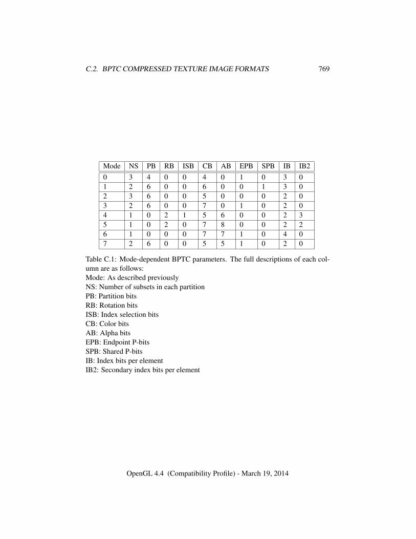
C.2. BPTC COMPRESSED TEXTURE IMAGE FORMATS 769
Mode NS PB RB ISB CB AB EPB SPB IB IB20 3 4 0 0 4 0 1 0 3 01 2 6 0 0 6 0 0 1 3 02 3 6 0 0 5 0 0 0 2 03 2 6 0 0 7 0 1 0 2 04 1 0 2 1 5 6 0 0 2 35 1 0 2 0 7 8 0 0 2 26 1 0 0 0 7 7 1 0 4 07 2 6 0 0 5 5 1 0 2 0
Table C.1: Mode-dependent BPTC parameters. The full descriptions of each col-umn are as follows:Mode: As described previouslyNS: Number of subsets in each partitionPB: Partition bitsRB: Rotation bitsISB: Index selection bitsCB: Color bitsAB: Alpha bitsEPB: Endpoint P-bitsSPB: Shared P-bitsIB: Index bits per elementIB2: Secondary index bits per element
OpenGL 4.4 (Compatibility Profile) - March 19, 2014
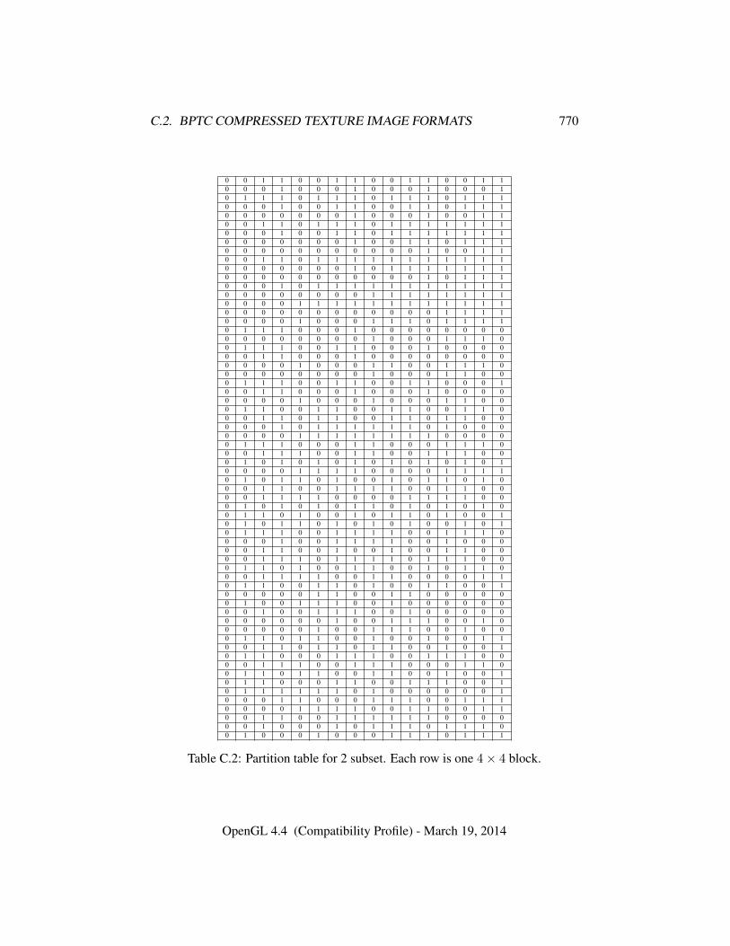
C.2. BPTC COMPRESSED TEXTURE IMAGE FORMATS 770
0 0 1 1 0 0 1 1 0 0 1 1 0 0 1 10 0 0 1 0 0 0 1 0 0 0 1 0 0 0 10 1 1 1 0 1 1 1 0 1 1 1 0 1 1 10 0 0 1 0 0 1 1 0 0 1 1 0 1 1 10 0 0 0 0 0 0 1 0 0 0 1 0 0 1 10 0 1 1 0 1 1 1 0 1 1 1 1 1 1 10 0 0 1 0 0 1 1 0 1 1 1 1 1 1 10 0 0 0 0 0 0 1 0 0 1 1 0 1 1 10 0 0 0 0 0 0 0 0 0 0 1 0 0 1 10 0 1 1 0 1 1 1 1 1 1 1 1 1 1 10 0 0 0 0 0 0 1 0 1 1 1 1 1 1 10 0 0 0 0 0 0 0 0 0 0 1 0 1 1 10 0 0 1 0 1 1 1 1 1 1 1 1 1 1 10 0 0 0 0 0 0 0 1 1 1 1 1 1 1 10 0 0 0 1 1 1 1 1 1 1 1 1 1 1 10 0 0 0 0 0 0 0 0 0 0 0 1 1 1 10 0 0 0 1 0 0 0 1 1 1 0 1 1 1 10 1 1 1 0 0 0 1 0 0 0 0 0 0 0 00 0 0 0 0 0 0 0 1 0 0 0 1 1 1 00 1 1 1 0 0 1 1 0 0 0 1 0 0 0 00 0 1 1 0 0 0 1 0 0 0 0 0 0 0 00 0 0 0 1 0 0 0 1 1 0 0 1 1 1 00 0 0 0 0 0 0 0 1 0 0 0 1 1 0 00 1 1 1 0 0 1 1 0 0 1 1 0 0 0 10 0 1 1 0 0 0 1 0 0 0 1 0 0 0 00 0 0 0 1 0 0 0 1 0 0 0 1 1 0 00 1 1 0 0 1 1 0 0 1 1 0 0 1 1 00 0 1 1 0 1 1 0 0 1 1 0 1 1 0 00 0 0 1 0 1 1 1 1 1 1 0 1 0 0 00 0 0 0 1 1 1 1 1 1 1 1 0 0 0 00 1 1 1 0 0 0 1 1 0 0 0 1 1 1 00 0 1 1 1 0 0 1 1 0 0 1 1 1 0 00 1 0 1 0 1 0 1 0 1 0 1 0 1 0 10 0 0 0 1 1 1 1 0 0 0 0 1 1 1 10 1 0 1 1 0 1 0 0 1 0 1 1 0 1 00 0 1 1 0 0 1 1 1 1 0 0 1 1 0 00 0 1 1 1 1 0 0 0 0 1 1 1 1 0 00 1 0 1 0 1 0 1 1 0 1 0 1 0 1 00 1 1 0 1 0 0 1 0 1 1 0 1 0 0 10 1 0 1 1 0 1 0 1 0 1 0 0 1 0 10 1 1 1 0 0 1 1 1 1 0 0 1 1 1 00 0 0 1 0 0 1 1 1 1 0 0 1 0 0 00 0 1 1 0 0 1 0 0 1 0 0 1 1 0 00 0 1 1 1 0 1 1 1 1 0 1 1 1 0 00 1 1 0 1 0 0 1 1 0 0 1 0 1 1 00 0 1 1 1 1 0 0 1 1 0 0 0 0 1 10 1 1 0 0 1 1 0 1 0 0 1 1 0 0 10 0 0 0 0 1 1 0 0 1 1 0 0 0 0 00 1 0 0 1 1 1 0 0 1 0 0 0 0 0 00 0 1 0 0 1 1 1 0 0 1 0 0 0 0 00 0 0 0 0 0 1 0 0 1 1 1 0 0 1 00 0 0 0 0 1 0 0 1 1 1 0 0 1 0 00 1 1 0 1 1 0 0 1 0 0 1 0 0 1 10 0 1 1 0 1 1 0 1 1 0 0 1 0 0 10 1 1 0 0 0 1 1 1 0 0 1 1 1 0 00 0 1 1 1 0 0 1 1 1 0 0 0 1 1 00 1 1 0 1 1 0 0 1 1 0 0 1 0 0 10 1 1 0 0 0 1 1 0 0 1 1 1 0 0 10 1 1 1 1 1 1 0 1 0 0 0 0 0 0 10 0 0 1 1 0 0 0 1 1 1 0 0 1 1 10 0 0 0 1 1 1 1 0 0 1 1 0 0 1 10 0 1 1 0 0 1 1 1 1 1 1 0 0 0 00 0 1 0 0 0 1 0 1 1 1 0 1 1 1 00 1 0 0 0 1 0 0 0 1 1 1 0 1 1 1
Table C.2: Partition table for 2 subset. Each row is one 4× 4 block.
OpenGL 4.4 (Compatibility Profile) - March 19, 2014
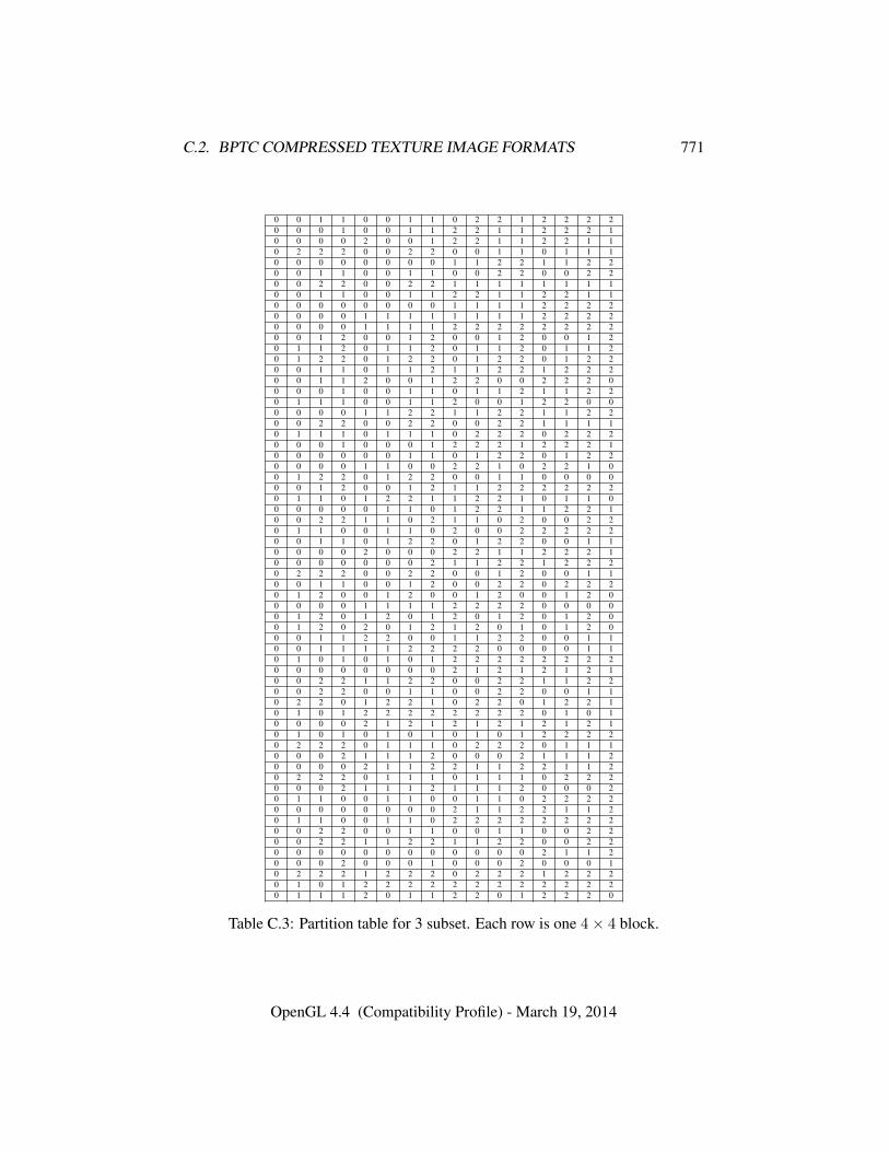
C.2. BPTC COMPRESSED TEXTURE IMAGE FORMATS 771
0 0 1 1 0 0 1 1 0 2 2 1 2 2 2 20 0 0 1 0 0 1 1 2 2 1 1 2 2 2 10 0 0 0 2 0 0 1 2 2 1 1 2 2 1 10 2 2 2 0 0 2 2 0 0 1 1 0 1 1 10 0 0 0 0 0 0 0 1 1 2 2 1 1 2 20 0 1 1 0 0 1 1 0 0 2 2 0 0 2 20 0 2 2 0 0 2 2 1 1 1 1 1 1 1 10 0 1 1 0 0 1 1 2 2 1 1 2 2 1 10 0 0 0 0 0 0 0 1 1 1 1 2 2 2 20 0 0 0 1 1 1 1 1 1 1 1 2 2 2 20 0 0 0 1 1 1 1 2 2 2 2 2 2 2 20 0 1 2 0 0 1 2 0 0 1 2 0 0 1 20 1 1 2 0 1 1 2 0 1 1 2 0 1 1 20 1 2 2 0 1 2 2 0 1 2 2 0 1 2 20 0 1 1 0 1 1 2 1 1 2 2 1 2 2 20 0 1 1 2 0 0 1 2 2 0 0 2 2 2 00 0 0 1 0 0 1 1 0 1 1 2 1 1 2 20 1 1 1 0 0 1 1 2 0 0 1 2 2 0 00 0 0 0 1 1 2 2 1 1 2 2 1 1 2 20 0 2 2 0 0 2 2 0 0 2 2 1 1 1 10 1 1 1 0 1 1 1 0 2 2 2 0 2 2 20 0 0 1 0 0 0 1 2 2 2 1 2 2 2 10 0 0 0 0 0 1 1 0 1 2 2 0 1 2 20 0 0 0 1 1 0 0 2 2 1 0 2 2 1 00 1 2 2 0 1 2 2 0 0 1 1 0 0 0 00 0 1 2 0 0 1 2 1 1 2 2 2 2 2 20 1 1 0 1 2 2 1 1 2 2 1 0 1 1 00 0 0 0 0 1 1 0 1 2 2 1 1 2 2 10 0 2 2 1 1 0 2 1 1 0 2 0 0 2 20 1 1 0 0 1 1 0 2 0 0 2 2 2 2 20 0 1 1 0 1 2 2 0 1 2 2 0 0 1 10 0 0 0 2 0 0 0 2 2 1 1 2 2 2 10 0 0 0 0 0 0 2 1 1 2 2 1 2 2 20 2 2 2 0 0 2 2 0 0 1 2 0 0 1 10 0 1 1 0 0 1 2 0 0 2 2 0 2 2 20 1 2 0 0 1 2 0 0 1 2 0 0 1 2 00 0 0 0 1 1 1 1 2 2 2 2 0 0 0 00 1 2 0 1 2 0 1 2 0 1 2 0 1 2 00 1 2 0 2 0 1 2 1 2 0 1 0 1 2 00 0 1 1 2 2 0 0 1 1 2 2 0 0 1 10 0 1 1 1 1 2 2 2 2 0 0 0 0 1 10 1 0 1 0 1 0 1 2 2 2 2 2 2 2 20 0 0 0 0 0 0 0 2 1 2 1 2 1 2 10 0 2 2 1 1 2 2 0 0 2 2 1 1 2 20 0 2 2 0 0 1 1 0 0 2 2 0 0 1 10 2 2 0 1 2 2 1 0 2 2 0 1 2 2 10 1 0 1 2 2 2 2 2 2 2 2 0 1 0 10 0 0 0 2 1 2 1 2 1 2 1 2 1 2 10 1 0 1 0 1 0 1 0 1 0 1 2 2 2 20 2 2 2 0 1 1 1 0 2 2 2 0 1 1 10 0 0 2 1 1 1 2 0 0 0 2 1 1 1 20 0 0 0 2 1 1 2 2 1 1 2 2 1 1 20 2 2 2 0 1 1 1 0 1 1 1 0 2 2 20 0 0 2 1 1 1 2 1 1 1 2 0 0 0 20 1 1 0 0 1 1 0 0 1 1 0 2 2 2 20 0 0 0 0 0 0 0 2 1 1 2 2 1 1 20 1 1 0 0 1 1 0 2 2 2 2 2 2 2 20 0 2 2 0 0 1 1 0 0 1 1 0 0 2 20 0 2 2 1 1 2 2 1 1 2 2 0 0 2 20 0 0 0 0 0 0 0 0 0 0 0 2 1 1 20 0 0 2 0 0 0 1 0 0 0 2 0 0 0 10 2 2 2 1 2 2 2 0 2 2 2 1 2 2 20 1 0 1 2 2 2 2 2 2 2 2 2 2 2 20 1 1 1 2 0 1 1 2 2 0 1 2 2 2 0
Table C.3: Partition table for 3 subset. Each row is one 4× 4 block.
OpenGL 4.4 (Compatibility Profile) - March 19, 2014
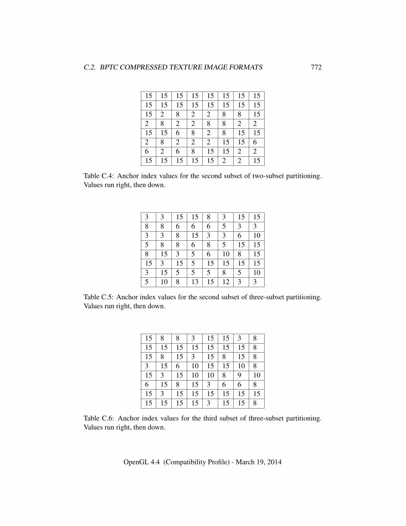
C.2. BPTC COMPRESSED TEXTURE IMAGE FORMATS 772
15 15 15 15 15 15 15 1515 15 15 15 15 15 15 1515 2 8 2 2 8 8 152 8 2 2 8 8 2 215 15 6 8 2 8 15 152 8 2 2 2 15 15 66 2 6 8 15 15 2 215 15 15 15 15 2 2 15
Table C.4: Anchor index values for the second subset of two-subset partitioning.Values run right, then down.
3 3 15 15 8 3 15 158 8 6 6 6 5 3 33 3 8 15 3 3 6 105 8 8 6 8 5 15 158 15 3 5 6 10 8 1515 3 15 5 15 15 15 153 15 5 5 5 8 5 105 10 8 13 15 12 3 3
Table C.5: Anchor index values for the second subset of three-subset partitioning.Values run right, then down.
15 8 8 3 15 15 3 815 15 15 15 15 15 15 815 8 15 3 15 8 15 83 15 6 10 15 15 10 815 3 15 10 10 8 9 106 15 8 15 3 6 6 815 3 15 15 15 15 15 1515 15 15 15 3 15 15 8
Table C.6: Anchor index values for the third subset of three-subset partitioning.Values run right, then down.
OpenGL 4.4 (Compatibility Profile) - March 19, 2014
C.2. BPTC COMPRESSED TEXTURE IMAGE FORMATS 773
the bits are reversed. v[a] is used as a shorthand for the one bit v[a : a]. As anexample, m[1 : 0], g2[4] would move the low two bits from the block into the lowtwo bits of m then the next bit of the block into bit 4 of g2. The variable namesgiven in the table will be referred to in the language below.
Subsets and indices work in much the same way as described for the fixed-pointformats above. If a float block has no partition bits, then it is a single-subset block.If it has partition bits, then it is a 2 subset block. The partition index references thefirst half of table C.2. Indices are read in the same way as the fixed-point formatsincluding obeying the anchor values for index 0 and as needed by table C.4.
In a single-subset blocks, the two endpoints are contained in r0, g0, b0 (hencee0) and r1, g1, b1 (hence e1). In a two-subset block, the endpoints for the secondsubset are in r2, g2, b2 and r3, g3, b3. The value in e0 is sign-extended if the formatof the texture is signed. The values in e1 (and e2 and e3 if the block is two-subset)are sign-extended if the format of the texture is signed or if the block mode hastransformed endpoints. If the mode has transformed endpoints, the values from e0are used as a base to offset all other endpoints, wrapped at the number of endpointbits. For example, r1 = (r0 + r1)&((1 << EPB)− 1).
Next, the endpoints are unquantized to maximize the usage of the bits and toensure that the negative ranges are oriented properly to interpolate as a two’s com-plement value. The following pseudocode assumes the computation is being doneusing sufficiently large intermediate values to avoid overflow. For the unsignedfloat format, we unquantize a value x to unq by:
if (EPB >= 15)unq = x;
else if (x == 0)unq = 0;
else if (x == ((1<<EPB)-1))unq = 0xFFFF;
elseunq = ((x << 15) + 0x4000) >> (EPB-1);
The signed float unquantization is similar, but needs to worry about orientingthe negative range:
s = 0;if (EPB >= 16)
unq = x;else {
if (x < 0) {
OpenGL 4.4 (Compatibility Profile) - March 19, 2014
C.3. ETC COMPRESSED TEXTURE IMAGE FORMATS 774
s = 1;x = -x;
}
if (x == 0)unq = 0;
else if (x >= ((1<<(EPB-1))-1))unq = 0x7FFF;
elseunq = ((x << 15) + 0x4000) >> (EPB-1);
if (s)unq = -unq;
}
After the endpoints are unquantized, interpolation proceeds as in the fixed-point formats above including the interpolation weight table.
The interpolated values are passed through a final unquantization step. Forthe unsigned format, this step simply multiplies by 31
64 . The signed format negatesnegative components, multiplies by 31
32 , then ORs in the sign bit if the original valuewas negative.
The resultant value should be a legal 16-bit half float which is then returned asa float to the shader.
C.3 ETC Compressed Texture Image Formats
The ETC formats form a family of related compressed texture image formats. Theyare designed to do different tasks, but also to be similar enough that hardware canbe reused between them. Each one is described in detail below, but we will firstgive an overview of each format and describe how it is similar to others and themain differences.
COMPRESSED_RGB8_ETC2 is a format for compressing RGB8 data. It is a su-perset of the older OES_compressed_ETC1_RGB8_texture format. This meansthat an older ETC1 texture can be decoded using by a COMPRESSED_RGB8_ETC2-compliant decoder, using the enum-value for COMPRESSED_RGB8_ETC2. Themain difference is that the newer version contains three new modes; the ‘T-mode’and the ‘H-mode’ which are good for sharp chrominance blocks and the ‘Planar’mode which is good for smooth blocks.
COMPRESSED_SRGB8_ETC2 is the same as COMPRESSED_RGB8_ETC2 withthe difference that the values should be interpeted as sRGB-values instead of RGB-
OpenGL 4.4 (Compatibility Profile) - March 19, 2014
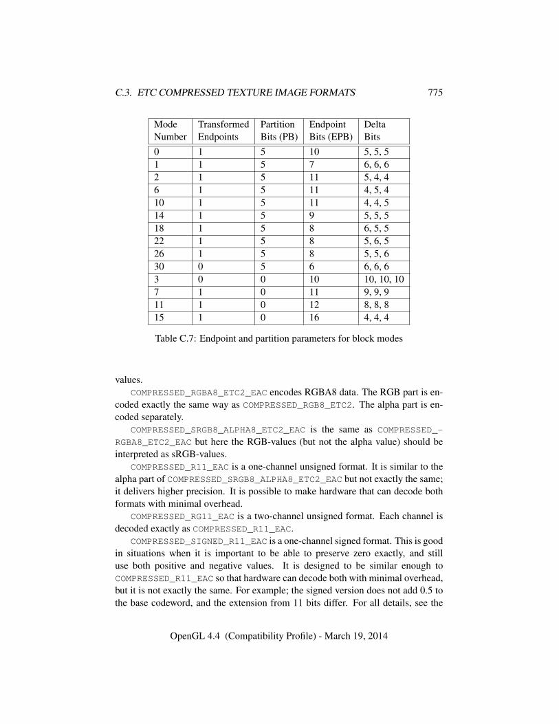
C.3. ETC COMPRESSED TEXTURE IMAGE FORMATS 775
Mode Transformed Partition Endpoint DeltaNumber Endpoints Bits (PB) Bits (EPB) Bits0 1 5 10 5, 5, 51 1 5 7 6, 6, 62 1 5 11 5, 4, 46 1 5 11 4, 5, 410 1 5 11 4, 4, 514 1 5 9 5, 5, 518 1 5 8 6, 5, 522 1 5 8 5, 6, 526 1 5 8 5, 5, 630 0 5 6 6, 6, 63 0 0 10 10, 10, 107 1 0 11 9, 9, 911 1 0 12 8, 8, 815 1 0 16 4, 4, 4
Table C.7: Endpoint and partition parameters for block modes
values.COMPRESSED_RGBA8_ETC2_EAC encodes RGBA8 data. The RGB part is en-
coded exactly the same way as COMPRESSED_RGB8_ETC2. The alpha part is en-coded separately.
COMPRESSED_SRGB8_ALPHA8_ETC2_EAC is the same as COMPRESSED_-
RGBA8_ETC2_EAC but here the RGB-values (but not the alpha value) should beinterpreted as sRGB-values.
COMPRESSED_R11_EAC is a one-channel unsigned format. It is similar to thealpha part of COMPRESSED_SRGB8_ALPHA8_ETC2_EAC but not exactly the same;it delivers higher precision. It is possible to make hardware that can decode bothformats with minimal overhead.
COMPRESSED_RG11_EAC is a two-channel unsigned format. Each channel isdecoded exactly as COMPRESSED_R11_EAC.
COMPRESSED_SIGNED_R11_EAC is a one-channel signed format. This is goodin situations when it is important to be able to preserve zero exactly, and stilluse both positive and negative values. It is designed to be similar enough toCOMPRESSED_R11_EAC so that hardware can decode both with minimal overhead,but it is not exactly the same. For example; the signed version does not add 0.5 tothe base codeword, and the extension from 11 bits differ. For all details, see the
OpenGL 4.4 (Compatibility Profile) - March 19, 2014
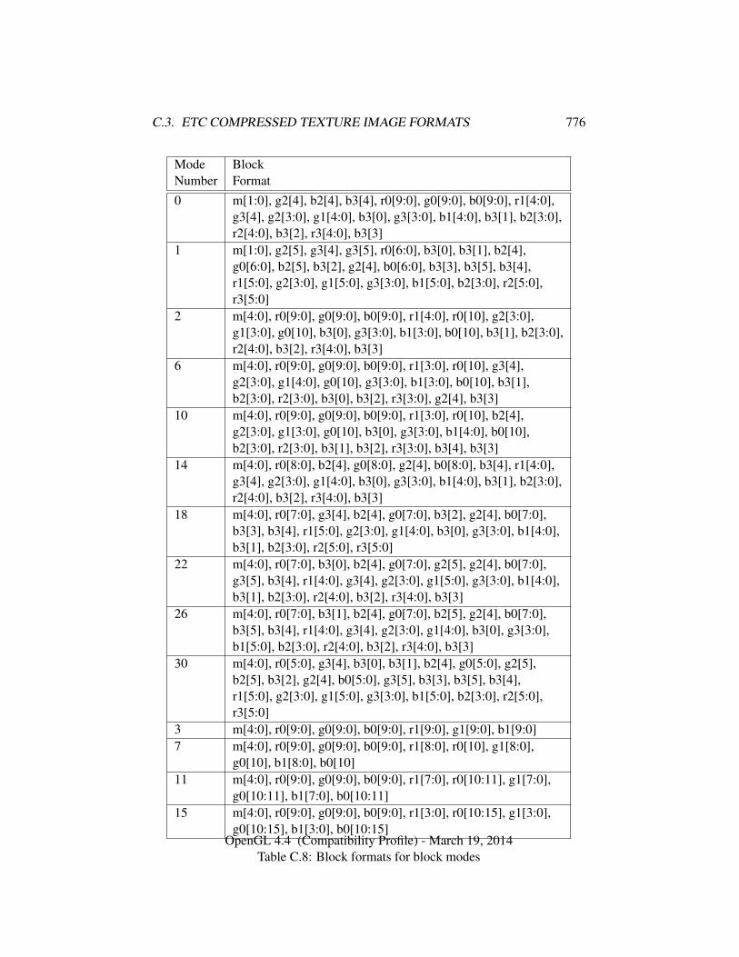
C.3. ETC COMPRESSED TEXTURE IMAGE FORMATS 776
Mode BlockNumber Format0 m[1:0], g2[4], b2[4], b3[4], r0[9:0], g0[9:0], b0[9:0], r1[4:0],
g3[4], g2[3:0], g1[4:0], b3[0], g3[3:0], b1[4:0], b3[1], b2[3:0],r2[4:0], b3[2], r3[4:0], b3[3]
1 m[1:0], g2[5], g3[4], g3[5], r0[6:0], b3[0], b3[1], b2[4],g0[6:0], b2[5], b3[2], g2[4], b0[6:0], b3[3], b3[5], b3[4],r1[5:0], g2[3:0], g1[5:0], g3[3:0], b1[5:0], b2[3:0], r2[5:0],r3[5:0]
2 m[4:0], r0[9:0], g0[9:0], b0[9:0], r1[4:0], r0[10], g2[3:0],g1[3:0], g0[10], b3[0], g3[3:0], b1[3:0], b0[10], b3[1], b2[3:0],r2[4:0], b3[2], r3[4:0], b3[3]
6 m[4:0], r0[9:0], g0[9:0], b0[9:0], r1[3:0], r0[10], g3[4],g2[3:0], g1[4:0], g0[10], g3[3:0], b1[3:0], b0[10], b3[1],b2[3:0], r2[3:0], b3[0], b3[2], r3[3:0], g2[4], b3[3]
10 m[4:0], r0[9:0], g0[9:0], b0[9:0], r1[3:0], r0[10], b2[4],g2[3:0], g1[3:0], g0[10], b3[0], g3[3:0], b1[4:0], b0[10],b2[3:0], r2[3:0], b3[1], b3[2], r3[3:0], b3[4], b3[3]
14 m[4:0], r0[8:0], b2[4], g0[8:0], g2[4], b0[8:0], b3[4], r1[4:0],g3[4], g2[3:0], g1[4:0], b3[0], g3[3:0], b1[4:0], b3[1], b2[3:0],r2[4:0], b3[2], r3[4:0], b3[3]
18 m[4:0], r0[7:0], g3[4], b2[4], g0[7:0], b3[2], g2[4], b0[7:0],b3[3], b3[4], r1[5:0], g2[3:0], g1[4:0], b3[0], g3[3:0], b1[4:0],b3[1], b2[3:0], r2[5:0], r3[5:0]
22 m[4:0], r0[7:0], b3[0], b2[4], g0[7:0], g2[5], g2[4], b0[7:0],g3[5], b3[4], r1[4:0], g3[4], g2[3:0], g1[5:0], g3[3:0], b1[4:0],b3[1], b2[3:0], r2[4:0], b3[2], r3[4:0], b3[3]
26 m[4:0], r0[7:0], b3[1], b2[4], g0[7:0], b2[5], g2[4], b0[7:0],b3[5], b3[4], r1[4:0], g3[4], g2[3:0], g1[4:0], b3[0], g3[3:0],b1[5:0], b2[3:0], r2[4:0], b3[2], r3[4:0], b3[3]
30 m[4:0], r0[5:0], g3[4], b3[0], b3[1], b2[4], g0[5:0], g2[5],b2[5], b3[2], g2[4], b0[5:0], g3[5], b3[3], b3[5], b3[4],r1[5:0], g2[3:0], g1[5:0], g3[3:0], b1[5:0], b2[3:0], r2[5:0],r3[5:0]
3 m[4:0], r0[9:0], g0[9:0], b0[9:0], r1[9:0], g1[9:0], b1[9:0]7 m[4:0], r0[9:0], g0[9:0], b0[9:0], r1[8:0], r0[10], g1[8:0],
g0[10], b1[8:0], b0[10]11 m[4:0], r0[9:0], g0[9:0], b0[9:0], r1[7:0], r0[10:11], g1[7:0],
g0[10:11], b1[7:0], b0[10:11]15 m[4:0], r0[9:0], g0[9:0], b0[9:0], r1[3:0], r0[10:15], g1[3:0],
g0[10:15], b1[3:0], b0[10:15]
Table C.8: Block formats for block modesOpenGL 4.4 (Compatibility Profile) - March 19, 2014
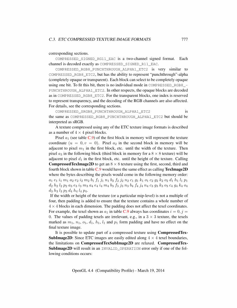
C.3. ETC COMPRESSED TEXTURE IMAGE FORMATS 777
corresponding sections.COMPRESSED_SIGNED_RG11_EAC is a two-channel signed format. Each
channel is decoded exactly as COMPRESSED_SIGNED_R11_EAC.COMPRESSED_RGB8_PUNCHTHROUGH_ALPHA1_ETC2 is very similar to
COMPRESSED_RGB8_ETC2, but has the ability to represent “punchthrough”-alpha(completely opaque or transparent). Each block can select to be completely opaqueusing one bit. To fit this bit, there is no individual mode in COMPRESSED_RGB8_-
PUNCHTHROUGH_ALPHA1_ETC2. In other respects, the opaque blocks are decodedas in COMPRESSED_RGB8_ETC2. For the transparent blocks, one index is reservedto represent transparency, and the decoding of the RGB channels are also affected.For details, see the corresponding sections.
COMPRESSED_SRGB8_PUNCHTHROUGH_ALPHA1_ETC2 isthe same as COMPRESSED_RGB8_PUNCHTHROUGH_ALPHA1_ETC2 but should beinterpreted as sRGB.
A texture compressed using any of the ETC texture image formats is describedas a number of 4× 4 pixel blocks.
Pixel a1 (see table C.9) of the first block in memory will represent the texturecoordinate (u = 0, v = 0). Pixel a2 in the second block in memory will beadjacent to pixel m1 in the first block, etc. until the width of the texture. Thenpixel a3 in the following block (third block in memory for a 8× 8 texture) will beadjacent to pixel d1 in the first block, etc. until the height of the texture. CallingCompressedTexImage2D to get an 8× 8 texture using the first, second, third andfourth block shown in table C.9 would have the same effect as calling TexImage2Dwhere the bytes describing the pixels would come in the following memory order:a1 e1 i1 m1 a2 e2 i2 m2 b1 f1 j1 n1 b2 f2 j2 n2 c1 g1 k1 o1 c2 g2 k2 o2 d1 h1 l1 p1d2 h2 l2 p2 a3 e3 i3 m3 a4 e4 i4 m4 b3 f3 j3 n3 b4 f4 j4 n4 c3 g3 k3 o3 c4 g4 k4 o4d3 h3 l3 p3 d4 h4 l4 p4.If the width or height of the texture (or a particular mip-level) is not a multiple of
four, then padding is added to ensure that the texture contains a whole number of4× 4 blocks in each dimension. The padding does not affect the texel coordinates.For example, the texel shown as a1 in table C.9 always has coordinates i = 0, j =0. The values of padding texels are irrelevant, e.g., in a 3 × 3 texture, the texelsmarked as m1, n1, o1, d1, h1, l1 and p1 form padding and have no effect on thefinal texture image.
It is possible to update part of a compressed texture using CompressedTex-SubImage2D: Since ETC images are easily edited along 4 × 4 texel boundaries,the limitations on CompressedTexSubImage2D are relaxed. CompressedTex-SubImage2D will result in an INVALID_OPERATION error only if one of the fol-lowing conditions occurs:
OpenGL 4.4 (Compatibility Profile) - March 19, 2014
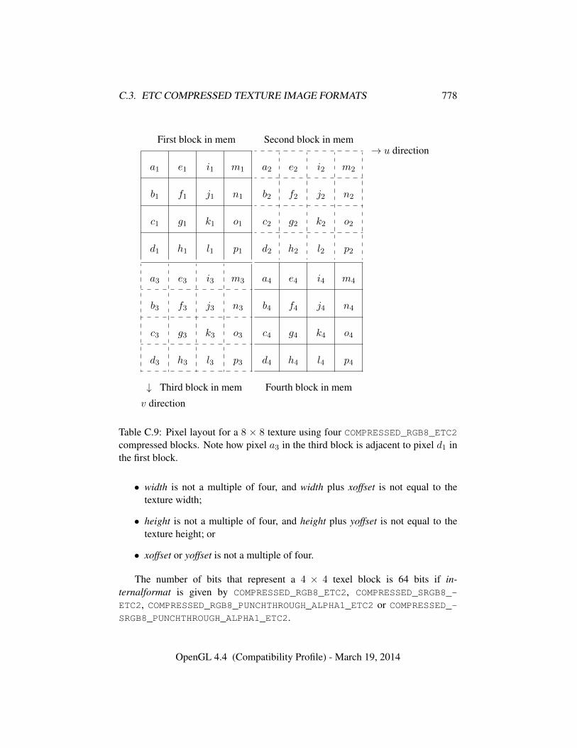
C.3. ETC COMPRESSED TEXTURE IMAGE FORMATS 778
First block in mem
a1 e1 i1 m1
b1 f1 j1 n1
c1 g1 k1 o1
d1 h1 l1 p1
Second block in mem
a2 e2 i2 m2
b2 f2 j2 n2
c2 g2 k2 o2
d2 h2 l2 p2
→ u direction
a3 e3 i3 m3
b3 f3 j3 n3
c3 g3 k3 o3
d3 h3 l3 p3
↓ Third block in mem
a4 e4 i4 m4
b4 f4 j4 n4
c4 g4 k4 o4
d4 h4 l4 p4
Fourth block in mem
v direction
Table C.9: Pixel layout for a 8 × 8 texture using four COMPRESSED_RGB8_ETC2compressed blocks. Note how pixel a3 in the third block is adjacent to pixel d1 inthe first block.
• width is not a multiple of four, and width plus xoffset is not equal to thetexture width;
• height is not a multiple of four, and height plus yoffset is not equal to thetexture height; or
• xoffset or yoffset is not a multiple of four.
The number of bits that represent a 4 × 4 texel block is 64 bits if in-ternalformat is given by COMPRESSED_RGB8_ETC2, COMPRESSED_SRGB8_-
ETC2, COMPRESSED_RGB8_PUNCHTHROUGH_ALPHA1_ETC2 or COMPRESSED_-SRGB8_PUNCHTHROUGH_ALPHA1_ETC2.
OpenGL 4.4 (Compatibility Profile) - March 19, 2014
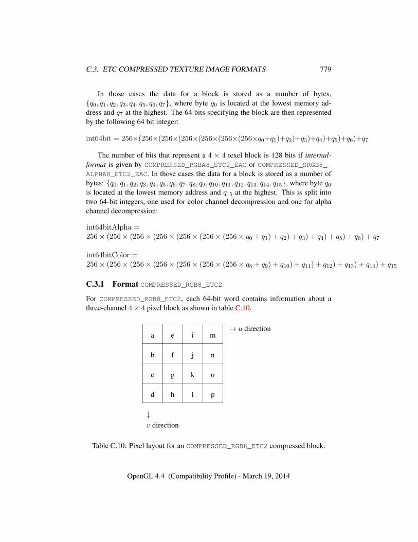
C.3. ETC COMPRESSED TEXTURE IMAGE FORMATS 779
In those cases the data for a block is stored as a number of bytes,{q0, q1, q2, q3, q4, q5, q6, q7}, where byte q0 is located at the lowest memory ad-dress and q7 at the highest. The 64 bits specifying the block are then representedby the following 64 bit integer:
int64bit = 256×(256×(256×(256×(256×(256×(256×q0+q1)+q2)+q3)+q4)+q5)+q6)+q7
The number of bits that represent a 4 × 4 texel block is 128 bits if internal-format is given by COMPRESSED_RGBA8_ETC2_EAC or COMPRESSED_SRGB8_-ALPHA8_ETC2_EAC. In those cases the data for a block is stored as a number ofbytes: {q0, q1, q2, q3, q4, q5, q6, q7, q8, q9, q10, q11, q12, q13, q14, q15}, where byte q0is located at the lowest memory address and q15 at the highest. This is split intotwo 64-bit integers, one used for color channel decompression and one for alphachannel decompression:
int64bitAlpha =256× (256× (256× (256× (256× (256× (256× q0 + q1) + q2) + q3) + q4) + q5) + q6) + q7
int64bitColor =256× (256× (256× (256× (256× (256× (256× q8 + q9) + q10) + q11) + q12) + q13) + q14) + q15
C.3.1 Format COMPRESSED_RGB8_ETC2
For COMPRESSED_RGB8_ETC2, each 64-bit word contains information about athree-channel 4× 4 pixel block as shown in table C.10.
a e i m
b f j n
c g k o
d h l p
↓v direction
→ u direction
Table C.10: Pixel layout for an COMPRESSED_RGB8_ETC2 compressed block.
OpenGL 4.4 (Compatibility Profile) - March 19, 2014
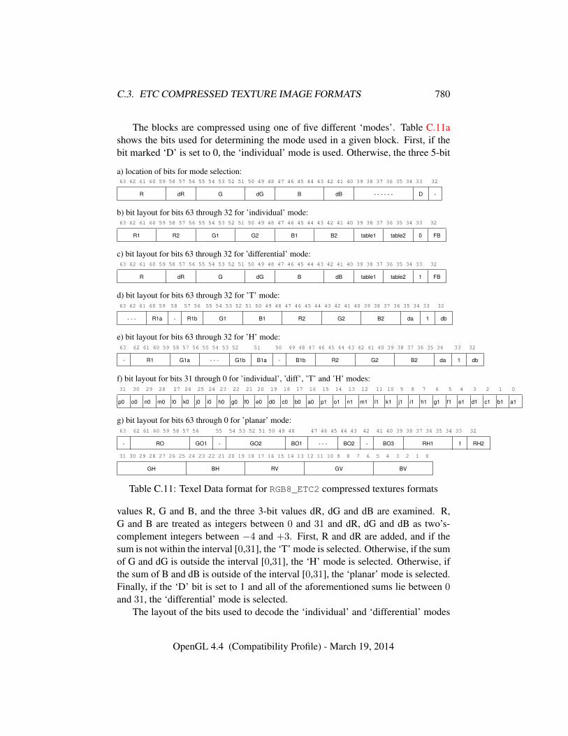
C.3. ETC COMPRESSED TEXTURE IMAGE FORMATS 780
The blocks are compressed using one of five different ‘modes’. Table C.11ashows the bits used for determining the mode used in a given block. First, if thebit marked ‘D’ is set to 0, the ‘individual’ mode is used. Otherwise, the three 5-bit
a) location of bits for mode selection:63 62 61 60 59 58 57 56 55 54 53 52 51 50 49 48 47 46 45 44 43 42 41 40 39 38 37 36 35 34 33 32
R dR G dG B dB - - - - - - D -
b) bit layout for bits 63 through 32 for ’individual’ mode:63 62 61 60 59 58 57 56 55 54 53 52 51 50 49 48 47 46 45 44 43 42 41 40 39 38 37 36 35 34 33 32
R1 R2 G1 G2 B1 B2 table1 table2 0 FB
c) bit layout for bits 63 through 32 for ’differential’ mode:63 62 61 60 59 58 57 56 55 54 53 52 51 50 49 48 47 46 45 44 43 42 41 40 39 38 37 36 35 34 33 32
R dR G dG B dB table1 table2 1 FB
d) bit layout for bits 63 through 32 for ’T’ mode:63 62 61 60 59 58 57 56 55 54 53 52 51 50 49 48 47 46 45 44 43 42 41 40 39 38 37 36 35 34 33 32
- - - R1a - R1b G1 B1 R2 G2 B2 da 1 db
e) bit layout for bits 63 through 32 for ’H’ mode:63 62 61 60 59 58 57 56 55 54 53 52 51 50 49 48 47 46 45 44 43 42 41 40 39 38 37 36 35 34 33 32
- R1 G1a - - - G1b B1a - B1b R2 G2 B2 da 1 db
f) bit layout for bits 31 through 0 for ’individual’, ’diff’, ’T’ and ’H’ modes:31 30 29 28 27 26 25 24 23 22 21 20 19 18 17 16 15 14 13 12 11 10 9 8 7 6 5 4 3 2 1 0
p0 o0 n0 m0 l0 k0 j0 i0 h0 g0 f0 e0 d0 c0 b0 a0 p1 o1 n1 m1 l1 k1 j1 i1 h1 g1 f1 e1 d1 c1 b1 a1
g) bit layout for bits 63 through 0 for ’planar’ mode:63 62 61 60 59 58 57 56 55 54 53 52 51 50 49 48 47 46 45 44 43 42 41 40 39 38 37 36 35 34 33 32
- RO GO1 - GO2 BO1 - - - BO2 - BO3 RH1 1 RH2
31 30 29 28 27 26 25 24 23 22 21 20 19 18 17 16 15 14 13 12 11 10 9 8 7 6 5 4 3 2 1 0
GH BH RV GV BV
Table C.11: Texel Data format for RGB8_ETC2 compressed textures formats
values R, G and B, and the three 3-bit values dR, dG and dB are examined. R,G and B are treated as integers between 0 and 31 and dR, dG and dB as two’s-complement integers between −4 and +3. First, R and dR are added, and if thesum is not within the interval [0,31], the ‘T’ mode is selected. Otherwise, if the sumof G and dG is outside the interval [0,31], the ‘H’ mode is selected. Otherwise, ifthe sum of B and dB is outside of the interval [0,31], the ‘planar’ mode is selected.Finally, if the ‘D’ bit is set to 1 and all of the aforementioned sums lie between 0and 31, the ‘differential’ mode is selected.
The layout of the bits used to decode the ‘individual’ and ‘differential’ modes
OpenGL 4.4 (Compatibility Profile) - March 19, 2014
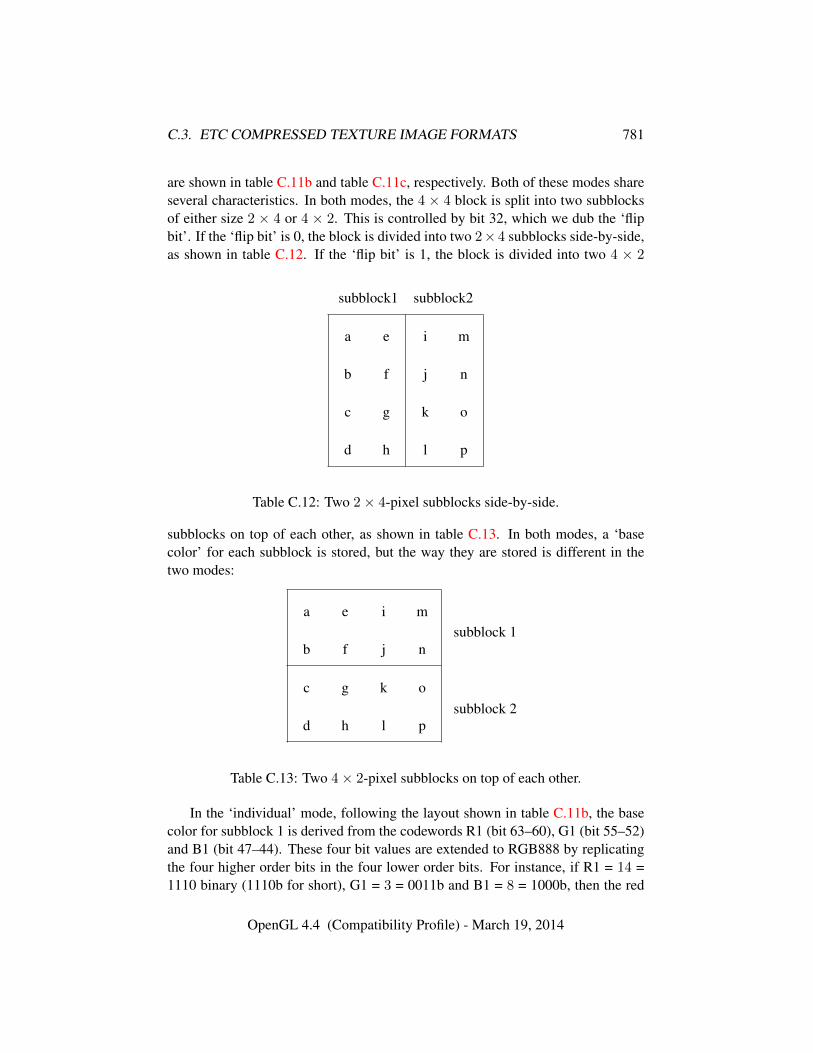
C.3. ETC COMPRESSED TEXTURE IMAGE FORMATS 781
are shown in table C.11b and table C.11c, respectively. Both of these modes shareseveral characteristics. In both modes, the 4 × 4 block is split into two subblocksof either size 2 × 4 or 4 × 2. This is controlled by bit 32, which we dub the ‘flipbit’. If the ‘flip bit’ is 0, the block is divided into two 2×4 subblocks side-by-side,as shown in table C.12. If the ‘flip bit’ is 1, the block is divided into two 4 × 2
subblock1 subblock2
a e i m
b f j n
c g k o
d h l p
Table C.12: Two 2× 4-pixel subblocks side-by-side.
subblocks on top of each other, as shown in table C.13. In both modes, a ‘basecolor’ for each subblock is stored, but the way they are stored is different in thetwo modes:
a e i m
b f j n
c g k o
d h l p
subblock 1
subblock 2
Table C.13: Two 4× 2-pixel subblocks on top of each other.
In the ‘individual’ mode, following the layout shown in table C.11b, the basecolor for subblock 1 is derived from the codewords R1 (bit 63–60), G1 (bit 55–52)and B1 (bit 47–44). These four bit values are extended to RGB888 by replicatingthe four higher order bits in the four lower order bits. For instance, if R1 = 14 =1110 binary (1110b for short), G1 = 3 = 0011b and B1 = 8 = 1000b, then the red
OpenGL 4.4 (Compatibility Profile) - March 19, 2014
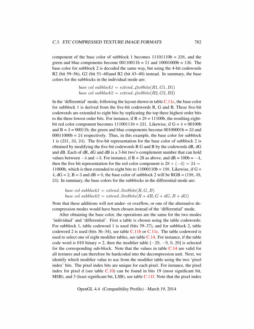
C.3. ETC COMPRESSED TEXTURE IMAGE FORMATS 782
component of the base color of subblock 1 becomes 11101110b = 238, and thegreen and blue components become 00110011b = 51 and 10001000b = 136. Thebase color for subblock 2 is decoded the same way, but using the 4-bit codewordsR2 (bit 59–56), G2 (bit 51–48)and B2 (bit 43–40) instead. In summary, the basecolors for the subblocks in the individual mode are:
base col subblock1 = extend 4to8bits(R1, G1, B1)base col subblock2 = extend 4to8bits(R2, G2, B2)
In the ‘differential’ mode, following the layout shown in table C.11c, the base colorfor subblock 1 is derived from the five-bit codewords R, G and B. These five-bitcodewords are extended to eight bits by replicating the top three highest order bitsto the three lowest order bits. For instance, if R = 28 = 11100b, the resulting eight-bit red color component becomes 11100111b = 231. Likewise, if G = 4 = 00100band B = 3 = 00011b, the green and blue components become 00100001b = 33 and00011000b = 24 respectively. Thus, in this example, the base color for subblock1 is (231, 33, 24). The five-bit representation for the base color of subblock 2 isobtained by modifying the five-bit codewords R G and B by the codewords dR, dGand dB. Each of dR, dG and dB is a 3-bit two’s-complement number that can holdvalues between −4 and +3. For instance, if R = 28 as above, and dR = 100b = −4,then the five bit representation for the red color component is 28 + (−4) = 24 =11000b, which is then extended to eight bits to 11000110b = 198. Likewise, if G =4, dG = 2, B = 3 and dB = 0, the base color of subblock 2 will be RGB = (198, 49,24). In summary, the base colors for the subblocks in the differential mode are:
base col subblock1 = extend 5to8bits(R,G,B)base col subblock2 = extend 5to8bits(R+ dR,G+ dG,B + dG)
Note that these additions will not under- or overflow, or one of the alternative de-compression modes would have been chosen instead of the ‘differential’ mode.
After obtaining the base color, the operations are the same for the two modes‘individual’ and ‘differential’. First a table is chosen using the table codewords:For subblock 1, table codeword 1 is used (bits 39–37), and for subblock 2, tablecodeword 2 is used (bits 36–34), see table C.11b or C.11c. The table codeword isused to select one of eight modifier tables, see table C.14. For instance, if the tablecode word is 010 binary = 2, then the modifier table [−29, −9, 9, 29] is selectedfor the corresponding sub-block. Note that the values in table C.14 are valid forall textures and can therefore be hardcoded into the decompression unit. Next, weidentify which modifier value to use from the modifier table using the two ‘pixelindex’ bits. The pixel index bits are unique for each pixel. For instance, the pixelindex for pixel d (see table C.10) can be found in bits 19 (most significant bit,MSB), and 3 (least significant bit, LSB), see table C.11f. Note that the pixel index
OpenGL 4.4 (Compatibility Profile) - March 19, 2014
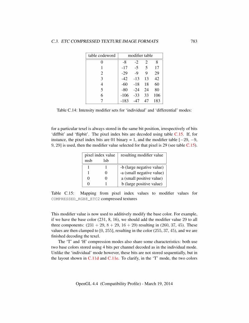
C.3. ETC COMPRESSED TEXTURE IMAGE FORMATS 783
table codeword modifier table0 -8 -2 2 81 -17 -5 5 172 -29 -9 9 293 -42 -13 13 424 -60 -18 18 605 -80 -24 24 806 -106 -33 33 1067 -183 -47 47 183
Table C.14: Intensity modifier sets for ‘individual’ and ‘differential’ modes:
for a particular texel is always stored in the same bit position, irrespectively of bits‘diffbit’ and ‘flipbit’. The pixel index bits are decoded using table C.15. If, forinstance, the pixel index bits are 01 binary = 1, and the modifier table [−29, −9,9, 29] is used, then the modifier value selected for that pixel is 29 (see table C.15).
pixel index value resulting modifier valuemsb lsb
1 1 -b (large negative value)1 0 -a (small negative value)0 0 a (small positive value)0 1 b (large positive value)
Table C.15: Mapping from pixel index values to modifier values forCOMPRESSED_RGB8_ETC2 compressed textures
This modifier value is now used to additively modify the base color. For example,if we have the base color (231, 8, 16), we should add the modifier value 29 to allthree components: (231 + 29, 8 + 29, 16 + 29) resulting in (260, 37, 45). Thesevalues are then clamped to [0, 255], resulting in the color (255, 37, 45), and we arefinished decoding the texel.
The ‘T’ and ‘H’ compression modes also share some characteristics: both usetwo base colors stored using 4 bits per channel decoded as in the individual mode.Unlike the ‘individual’ mode however, these bits are not stored sequentially, but inthe layout shown in C.11d and C.11e. To clarify, in the ‘T’ mode, the two colors
OpenGL 4.4 (Compatibility Profile) - March 19, 2014
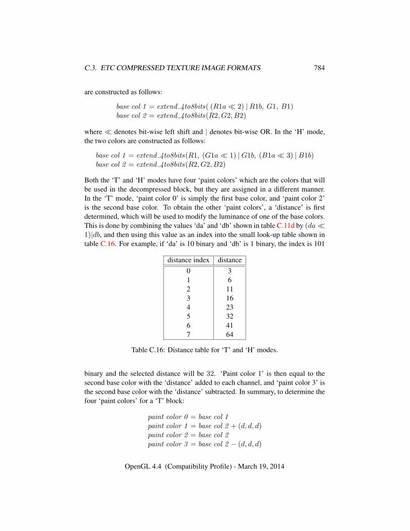
C.3. ETC COMPRESSED TEXTURE IMAGE FORMATS 784
are constructed as follows:
base col 1 = extend 4to8bits( (R1a� 2) |R1b, G1, B1)base col 2 = extend 4to8bits(R2, G2, B2)
where � denotes bit-wise left shift and | denotes bit-wise OR. In the ‘H’ mode,the two colors are constructed as follows:
base col 1 = extend 4to8bits(R1, (G1a� 1) |G1b, (B1a� 3) |B1b)base col 2 = extend 4to8bits(R2, G2, B2)
Both the ‘T’ and ‘H’ modes have four ‘paint colors’ which are the colors that willbe used in the decompressed block, but they are assigned in a different manner.In the ‘T’ mode, ‘paint color 0’ is simply the first base color, and ‘paint color 2’is the second base color. To obtain the other ‘paint colors’, a ‘distance’ is firstdetermined, which will be used to modify the luminance of one of the base colors.This is done by combining the values ‘da’ and ‘db’ shown in table C.11d by (da�1)|db, and then using this value as an index into the small look-up table shown intable C.16. For example, if ‘da’ is 10 binary and ‘db’ is 1 binary, the index is 101
distance index distance0 31 62 113 164 235 326 417 64
Table C.16: Distance table for ‘T’ and ‘H’ modes.
binary and the selected distance will be 32. ‘Paint color 1’ is then equal to thesecond base color with the ‘distance’ added to each channel, and ‘paint color 3’ isthe second base color with the ‘distance’ subtracted. In summary, to determine thefour ‘paint colors’ for a ‘T’ block:
paint color 0 = base col 1paint color 1 = base col 2 + (d, d, d)paint color 2 = base col 2paint color 3 = base col 2 − (d, d, d)
OpenGL 4.4 (Compatibility Profile) - March 19, 2014
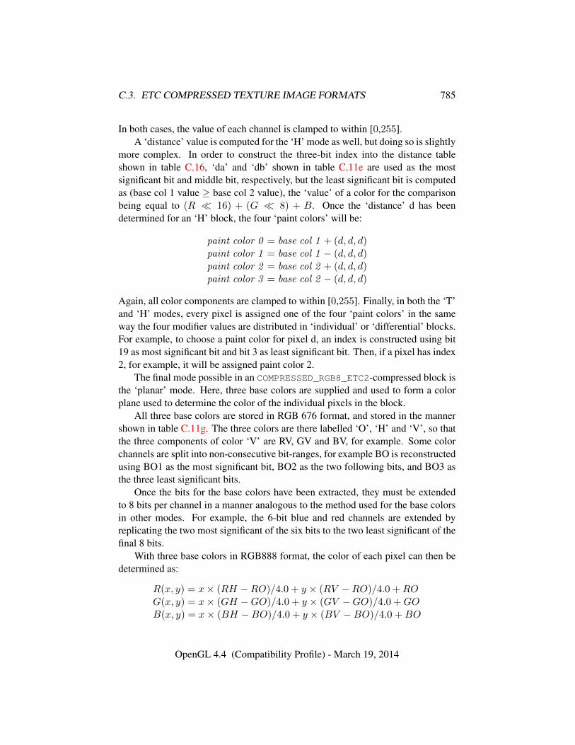
C.3. ETC COMPRESSED TEXTURE IMAGE FORMATS 785
In both cases, the value of each channel is clamped to within [0,255].A ‘distance’ value is computed for the ‘H’ mode as well, but doing so is slightly
more complex. In order to construct the three-bit index into the distance tableshown in table C.16, ‘da’ and ‘db’ shown in table C.11e are used as the mostsignificant bit and middle bit, respectively, but the least significant bit is computedas (base col 1 value ≥ base col 2 value), the ‘value’ of a color for the comparisonbeing equal to (R � 16) + (G � 8) + B. Once the ‘distance’ d has beendetermined for an ‘H’ block, the four ‘paint colors’ will be:
paint color 0 = base col 1 + (d, d, d)paint color 1 = base col 1 − (d, d, d)paint color 2 = base col 2 + (d, d, d)paint color 3 = base col 2 − (d, d, d)
Again, all color components are clamped to within [0,255]. Finally, in both the ‘T’and ‘H’ modes, every pixel is assigned one of the four ‘paint colors’ in the sameway the four modifier values are distributed in ‘individual’ or ‘differential’ blocks.For example, to choose a paint color for pixel d, an index is constructed using bit19 as most significant bit and bit 3 as least significant bit. Then, if a pixel has index2, for example, it will be assigned paint color 2.
The final mode possible in an COMPRESSED_RGB8_ETC2-compressed block isthe ‘planar’ mode. Here, three base colors are supplied and used to form a colorplane used to determine the color of the individual pixels in the block.
All three base colors are stored in RGB 676 format, and stored in the mannershown in table C.11g. The three colors are there labelled ‘O’, ‘H’ and ‘V’, so thatthe three components of color ‘V’ are RV, GV and BV, for example. Some colorchannels are split into non-consecutive bit-ranges, for example BO is reconstructedusing BO1 as the most significant bit, BO2 as the two following bits, and BO3 asthe three least significant bits.
Once the bits for the base colors have been extracted, they must be extendedto 8 bits per channel in a manner analogous to the method used for the base colorsin other modes. For example, the 6-bit blue and red channels are extended byreplicating the two most significant of the six bits to the two least significant of thefinal 8 bits.
With three base colors in RGB888 format, the color of each pixel can then bedetermined as:
R(x, y) = x× (RH −RO)/4.0 + y × (RV −RO)/4.0 +ROG(x, y) = x× (GH −GO)/4.0 + y × (GV −GO)/4.0 +GOB(x, y) = x× (BH −BO)/4.0 + y × (BV −BO)/4.0 +BO
OpenGL 4.4 (Compatibility Profile) - March 19, 2014
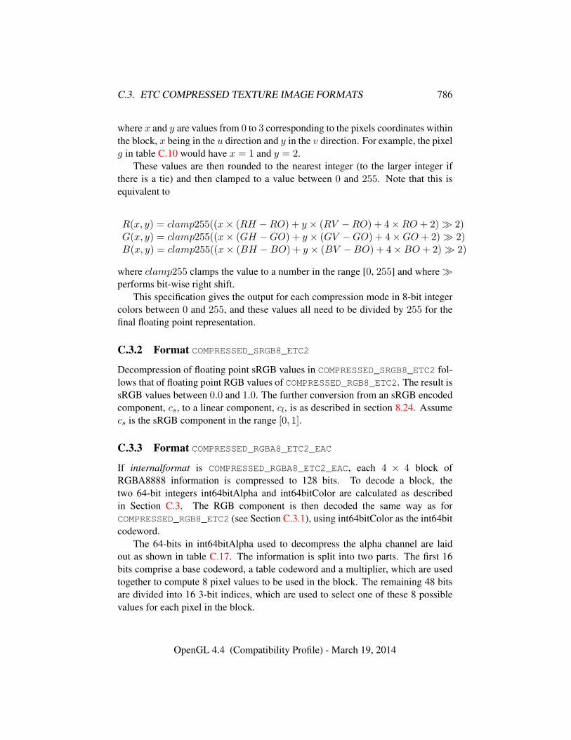
C.3. ETC COMPRESSED TEXTURE IMAGE FORMATS 786
where x and y are values from 0 to 3 corresponding to the pixels coordinates withinthe block, x being in the u direction and y in the v direction. For example, the pixelg in table C.10 would have x = 1 and y = 2.
These values are then rounded to the nearest integer (to the larger integer ifthere is a tie) and then clamped to a value between 0 and 255. Note that this isequivalent to
R(x, y) = clamp255((x× (RH −RO) + y × (RV −RO) + 4×RO + 2)� 2)G(x, y) = clamp255((x× (GH −GO) + y × (GV −GO) + 4×GO + 2)� 2)B(x, y) = clamp255((x× (BH −BO) + y × (BV −BO) + 4×BO + 2)� 2)
where clamp255 clamps the value to a number in the range [0, 255] and where�performs bit-wise right shift.
This specification gives the output for each compression mode in 8-bit integercolors between 0 and 255, and these values all need to be divided by 255 for thefinal floating point representation.
C.3.2 Format COMPRESSED_SRGB8_ETC2
Decompression of floating point sRGB values in COMPRESSED_SRGB8_ETC2 fol-lows that of floating point RGB values of COMPRESSED_RGB8_ETC2. The result issRGB values between 0.0 and 1.0. The further conversion from an sRGB encodedcomponent, cs, to a linear component, cl, is as described in section 8.24. Assumecs is the sRGB component in the range [0, 1].
C.3.3 Format COMPRESSED_RGBA8_ETC2_EAC
If internalformat is COMPRESSED_RGBA8_ETC2_EAC, each 4 × 4 block ofRGBA8888 information is compressed to 128 bits. To decode a block, thetwo 64-bit integers int64bitAlpha and int64bitColor are calculated as describedin Section C.3. The RGB component is then decoded the same way as forCOMPRESSED_RGB8_ETC2 (see Section C.3.1), using int64bitColor as the int64bitcodeword.
The 64-bits in int64bitAlpha used to decompress the alpha channel are laidout as shown in table C.17. The information is split into two parts. The first 16bits comprise a base codeword, a table codeword and a multiplier, which are usedtogether to compute 8 pixel values to be used in the block. The remaining 48 bitsare divided into 16 3-bit indices, which are used to select one of these 8 possiblevalues for each pixel in the block.
OpenGL 4.4 (Compatibility Profile) - March 19, 2014
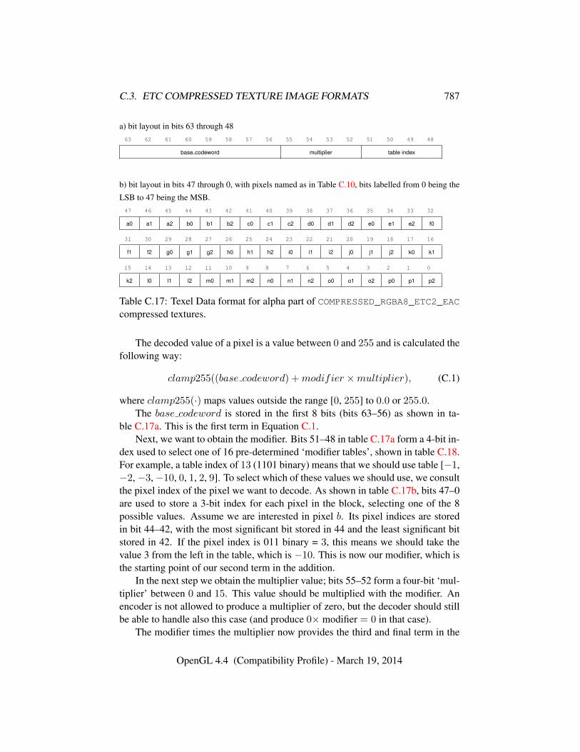
C.3. ETC COMPRESSED TEXTURE IMAGE FORMATS 787
a) bit layout in bits 63 through 4863 62 61 60 59 58 57 56 55 54 53 52 51 50 49 48
base codeword multiplier table index
b) bit layout in bits 47 through 0, with pixels named as in Table C.10, bits labelled from 0 being the
LSB to 47 being the MSB.47 46 45 44 43 42 41 40 39 38 37 36 35 34 33 32
a0 a1 a2 b0 b1 b2 c0 c1 c2 d0 d1 d2 e0 e1 e2 f0
31 30 29 28 27 26 25 24 23 22 21 20 19 18 17 16
f1 f2 g0 g1 g2 h0 h1 h2 i0 i1 i2 j0 j1 j2 k0 k1
15 14 13 12 11 10 9 8 7 6 5 4 3 2 1 0
k2 l0 l1 l2 m0 m1 m2 n0 n1 n2 o0 o1 o2 p0 p1 p2
Table C.17: Texel Data format for alpha part of COMPRESSED_RGBA8_ETC2_EACcompressed textures.
The decoded value of a pixel is a value between 0 and 255 and is calculated thefollowing way:
clamp255((base codeword) +modifier ×multiplier), (C.1)
where clamp255(·) maps values outside the range [0, 255] to 0.0 or 255.0.The base codeword is stored in the first 8 bits (bits 63–56) as shown in ta-
ble C.17a. This is the first term in Equation C.1.Next, we want to obtain the modifier. Bits 51–48 in table C.17a form a 4-bit in-
dex used to select one of 16 pre-determined ‘modifier tables’, shown in table C.18.For example, a table index of 13 (1101 binary) means that we should use table [−1,−2,−3,−10, 0, 1, 2, 9]. To select which of these values we should use, we consultthe pixel index of the pixel we want to decode. As shown in table C.17b, bits 47–0are used to store a 3-bit index for each pixel in the block, selecting one of the 8possible values. Assume we are interested in pixel b. Its pixel indices are storedin bit 44–42, with the most significant bit stored in 44 and the least significant bitstored in 42. If the pixel index is 011 binary = 3, this means we should take thevalue 3 from the left in the table, which is −10. This is now our modifier, which isthe starting point of our second term in the addition.
In the next step we obtain the multiplier value; bits 55–52 form a four-bit ‘mul-tiplier’ between 0 and 15. This value should be multiplied with the modifier. Anencoder is not allowed to produce a multiplier of zero, but the decoder should stillbe able to handle also this case (and produce 0× modifier = 0 in that case).
The modifier times the multiplier now provides the third and final term in the
OpenGL 4.4 (Compatibility Profile) - March 19, 2014
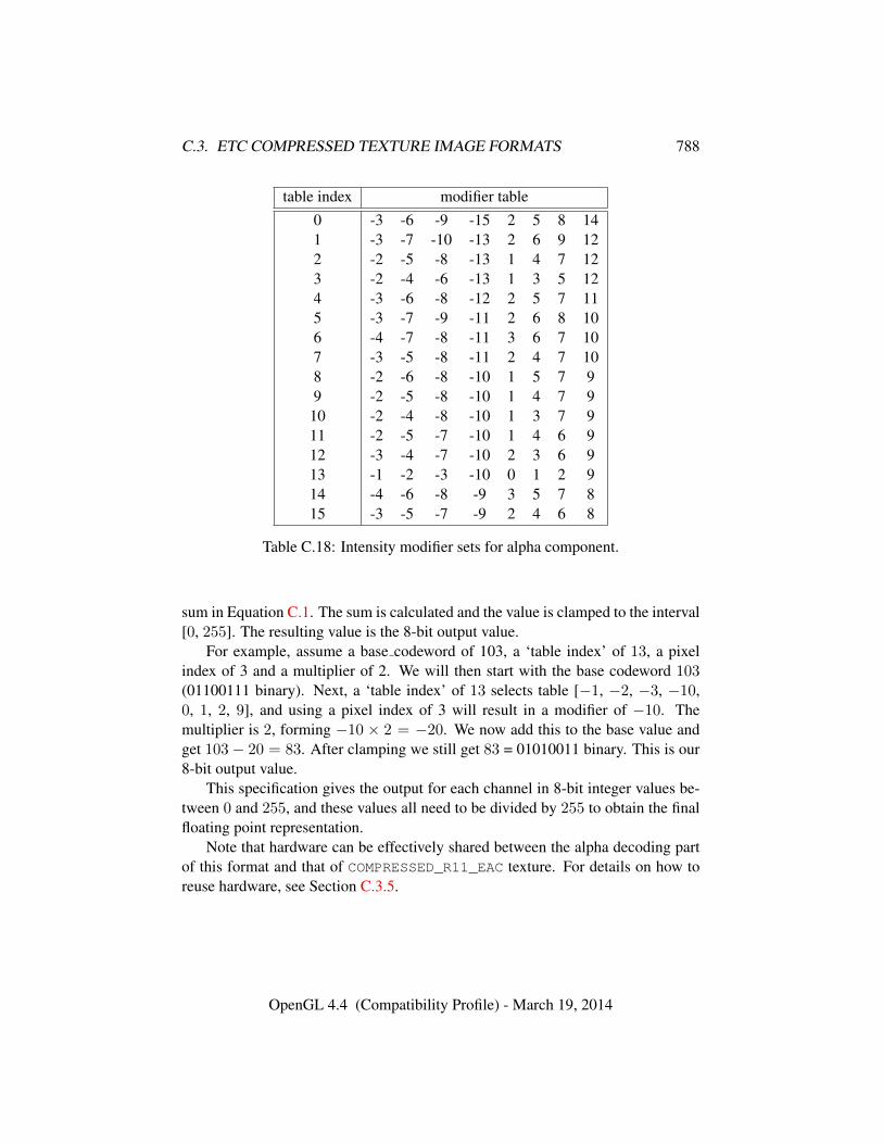
C.3. ETC COMPRESSED TEXTURE IMAGE FORMATS 788
table index modifier table0 -3 -6 -9 -15 2 5 8 141 -3 -7 -10 -13 2 6 9 122 -2 -5 -8 -13 1 4 7 123 -2 -4 -6 -13 1 3 5 124 -3 -6 -8 -12 2 5 7 115 -3 -7 -9 -11 2 6 8 106 -4 -7 -8 -11 3 6 7 107 -3 -5 -8 -11 2 4 7 108 -2 -6 -8 -10 1 5 7 99 -2 -5 -8 -10 1 4 7 910 -2 -4 -8 -10 1 3 7 911 -2 -5 -7 -10 1 4 6 912 -3 -4 -7 -10 2 3 6 913 -1 -2 -3 -10 0 1 2 914 -4 -6 -8 -9 3 5 7 815 -3 -5 -7 -9 2 4 6 8
Table C.18: Intensity modifier sets for alpha component.
sum in Equation C.1. The sum is calculated and the value is clamped to the interval[0, 255]. The resulting value is the 8-bit output value.
For example, assume a base codeword of 103, a ‘table index’ of 13, a pixelindex of 3 and a multiplier of 2. We will then start with the base codeword 103(01100111 binary). Next, a ‘table index’ of 13 selects table [−1, −2, −3, −10,0, 1, 2, 9], and using a pixel index of 3 will result in a modifier of −10. Themultiplier is 2, forming −10 × 2 = −20. We now add this to the base value andget 103− 20 = 83. After clamping we still get 83 = 01010011 binary. This is our8-bit output value.
This specification gives the output for each channel in 8-bit integer values be-tween 0 and 255, and these values all need to be divided by 255 to obtain the finalfloating point representation.
Note that hardware can be effectively shared between the alpha decoding partof this format and that of COMPRESSED_R11_EAC texture. For details on how toreuse hardware, see Section C.3.5.
OpenGL 4.4 (Compatibility Profile) - March 19, 2014
C.3. ETC COMPRESSED TEXTURE IMAGE FORMATS 789
C.3.4 Format COMPRESSED_SRGB8_ALPHA8_ETC2_EAC
Decompression of floating point sRGB values in COMPRESSED_SRGB8_-
ALPHA8_ETC2_EAC follows that of floating point RGB values of RGBA8_ETC2_-EAC. The result is sRGB values between 0.0 and 1.0. The further conversion froman sRGB encoded component, cs, to a linear component, cl, is as described insection 8.24. Assume cs is the sRGB component in the range [0, 1].
The alpha component of COMPRESSED_SRGB8_ALPHA8_ETC2_EAC is donein the same way as for COMPRESSED_RGBA8_ETC2_EAC.
C.3.5 Format COMPRESSED_R11_EAC
The number of bits to represent a 4 × 4 texel block is 64 bits if internalformatis given by COMPRESSED_R11_EAC. In that case the data for a block is stored asa number of bytes, {q0, q1, q2, q3, q4, q5, q6, q7}, where byte q0 is located at thelowest memory address and q7 at the highest. The red component of the 4 × 4block is then represented by the following 64 bit integer:
int64bit = 256×(256×(256×(256×(256×(256×(256×q0+q1)+q2)+q3)+q4)+q5)+q6)+q7
This 64-bit word contains information about a single-channel 4×4 pixel blockas shown in table C.10. The 64-bit word is split into two parts. The first 16 bitscomprise a base codeword, a table codeword and a multiplier. The remaining 48bits are divided into 16 3-bit indices, which are used to select one of the 8 possiblevalues for each pixel in the block, as shown in table C.17.
The decoded value is calculated as
clamp1((base codeword+0.5)× 1
255.875+modifier×multiplier× 1
255.875),
(C.2)where clamp1(·) maps values outside the range [0.0, 1.0] to 0.0 or 1.0.
We will now go into detail how the decoding is done. The result will be an11-bit fixed point number where 0 represents 0.0 and 2047 represents 1.0. This isthe exact representation for the decoded value. However, some implementationsmay use, e.g., 16-bits of accuracy for filtering. In such a case the 11-bit value willbe extended to 16 bits in a predefined way, which we will describe later.
To get a value between 0 and 2047 we must multiply Equation C.2 by 2047.0:
clamp2((base codeword+0.5)× 2047.0
255.875+modifier×multiplier× 2047.0
255.875),
(C.3)
OpenGL 4.4 (Compatibility Profile) - March 19, 2014
C.3. ETC COMPRESSED TEXTURE IMAGE FORMATS 790
where clamp2(·) clamps to the range [0.0, 2047.0]. Since 2047.0/255.875 is ex-actly 8.0, the above equation can be written as
clamp2(base codeword× 8 + 4 +modifier ×multiplier × 8) (C.4)
The base codeword is stored in the first 8 bits as shown in table C.17a. Bits 63–56in each block represent an eight-bit integer (base codeword) which is multipliedby 8 by shifting three steps to the left. We can add 4 to this value without ad-dition logic by just inserting 100 binary in the last three bits after the shift. Forexample, if base codeword is 129 = 10000001 binary (or 10000001b for short),the shifted value is 10000001000b and the shifted value including the +4 term is10000001100b = 1036 = 129× 8 + 4. Hence we have summed together the firsttwo terms of the sum in Equation C.4.
Next, we want to obtain the modifier. Bits 51–48 form a 4-bit index usedto select one of 16 pre-determined ‘modifier tables’, shown in table C.18. Forexample, a table index of 13 (1101 binary) means that we should use table [−1,−2, −3, −10, 0, 1, 2, 9]. To select which of these values we should use, weconsult the pixel index of the pixel we want to decode. Bits 47–0 are used to storea 3-bit index for each pixel in the block, selecting one of the 8 possible values.Assume we are interested in pixel b. Its pixel indices are stored in bit 44–42, withthe most significant bit stored in 44 and the least significant bit stored in 42. If thepixel index is 011 binary = 3, this means we should take the value 3 from the leftin the table, which is −10. This is now our modifier, which is the starting point ofour second term in the sum.
In the next step we obtain the multiplier value; bits 55–52 form a four-bit ‘mul-tiplier’ between 0 and 15. We will later treat what happens if the multiplier valueis zero, but if it is nonzero, it should be multiplied width the modifier. This productshould then be shifted three steps to the left to implement the ×8 multiplication.The result now provides the third and final term in the sum in C.4. The sum is cal-culated and the result is clamped to a value in the interval [0, 2047]. The resultingvalue is the 11-bit output value.
For example, assume a base codeword of 103, a ‘table index’ of 13, a pixelindex of 3 and a multiplier of 2 . We will then first multiply the base codeword103 (01100111b) by 8 by left-shifting it (0110111000b) and then add 4 resultingin 0110111100b = 828 = 103 × 8 + 4. Next, a ‘table index’ of 13 selects table[−1, −2, −3, −10, 0, 1, 2, 9], and using a pixel index of 3 will result in a modifierof −10. The multiplier is nonzero, which means that we should multiply it withthe modifier, forming −10 × 2 = −20 = 111111101100b. This value should inturn be multiplied by 8 by left-shifting it three steps: 111101100000b = −160.We now add this to the base value and get 828 − 160 = 668. After clamping we
OpenGL 4.4 (Compatibility Profile) - March 19, 2014
C.3. ETC COMPRESSED TEXTURE IMAGE FORMATS 791
still get 668 = 01010011100b. This is our 11-bit output value, which representsthe value 668/2047 = 0.32633121 . . .
If the multiplier value is zero (i.e., the multiplier bits 55–52 are all zero), weshould set the multiplier to 1.0/8.0. Equation C.4 can then be simplified to
clamp2(base codeword× 8 + 4 +modifier) (C.5)
As an example, assume a base codeword of 103, a ‘table index’ of 13, a pixelindex of 3 and a multiplier value of 0. We treat the base codeword the same way,getting 828 = 103 × 8 + 4. The modifier is still -10. But the multiplier shouldnow be 1/8, which means that third term becomes −10 × (1/8) × 8 = −10. Thesum therefore becomes 828 − 10 = 818. After clamping we still get 818 =01100110010b, and this is our 11-bit output value, and it represents 818/2047 =0.39960918 . . .
Some GL implementations may find it convenient to use 16-bit values forfurther processing. In this case, the 11-bit value should be extended using bitreplication. An 11-bit value x is extended to 16 bits through (x � 5) + (x �6). For example, the value 668 = 01010011100b should be extended to0101001110001010b = 21386.
In general, the implementation may extend the value to any number of bits thatis convenient for further processing, e.g., 32 bits. In these cases, bit replicationshould be used. On the other hand, an implementation is not allowed to truncatethe 11-bit value to less than 11 bits.
Note that the method does not have the same reconstruction levels as thealpha part in the COMPRESSED_RGBA8_ETC2_EAC-format. For instance, for abase value of 255 and a table value of 0, the alpha part of the COMPRESSED_-
RGBA8_ETC2_EAC-format will represent a value of (255 + 0)/255.0 = 1.0 ex-actly. In COMPRESSED_R11_EAC the same base value and table value will in-stead represent (255.5 + 0)/255.875 = 0.99853444 . . . That said, it is still possi-ble to decode the alpha part of the COMPRESSED_RGBA8_ETC2_EAC-format usingCOMPRESSED_R11_EAC-hardware. This is done by truncating the 11-bit numberto 8 bits. As an example, if base value = 255 and table value = 0, we get the 11-bitvalue (255 × 8 + 4 + 0) = 2044 = 1111111100b, which after truncation becomesthe 8-bit value 11111111b = 255 which is exactly the correct value according to theCOMPRESSED_RGBA8_ETC2_EAC. Clamping has to be done to [0, 255] after trun-cation for COMPRESSED_RGBA8_ETC2_EAC-decoding. Care must also be taken tohandle the case when the multiplier value is zero. In the 11-bit version, this meansmultiplying by 1/8, but in the 8-bit version, it really means multiplication by 0.Thus, the decoder will have to know if it is a COMPRESSED_RGBA8_ETC2_EAC
texture or a COMPRESSED_R11_EAC texture to decode correctly, but the hardwarecan be 100% shared.
OpenGL 4.4 (Compatibility Profile) - March 19, 2014
C.3. ETC COMPRESSED TEXTURE IMAGE FORMATS 792
As stated above, a base value of 255 and a table value of 0 will represent avalue of (255.5 + 0)/255.875 = 0.99853444 . . ., and this does not reach 1.0 eventhough 255 is the highest possible base codeword. However, it is still possible toreach a pixel value of 1.0 since a modifier other than 0 can be used. Indeed, half ofthe modifiers will often produce a value of 1.0. As an example, assume we choosethe base value 255, a multiplier of 1 and the modifier table [−3 −5 −7 −9 2 4 6 8]. Starting with C.4,
clamp1((base codeword+0.5)× 1
255.875+table value×multiplier× 1
255.875)
we get
clamp1((255+0.5)× 1
255.875+[−3 −5 −7 −9 2 4 6 8
]× 1
255.875)
which equals
clamp1([
0.987 0.979 0.971 0.963 1.00 1.01 1.02 1.03])
or after clamping[0.987 0.979 0.971 0.963 1.00 1.00 1.00 1.00
]which shows that several values can be 1.0, even though the base value does notreach 1.0. The same reasoning goes for 0.0.
C.3.6 Format COMPRESSED_RG11_EAC
The number of bits to represent a 4 × 4 texel block is 128 bits if internalformatis given by COMPRESSED_RG11_EAC. In that case the data for a block is stored asa number of bytes, {q0, q1, q2, q3, q4, q5, q6, q7, p0, p1, p2, p3, p4, p5, p6, p7} wherebyte q0 is located at the lowest memory address and p7 at the highest. The 128 bitsspecifying the block are then represented by the following two 64 bit integers:
int64bit0 = 256×(256×(256×(256×(256×(256×(256×q0+q1)+q2)+q3)+q4)+q5)+q6)+q7
int64bit1 = 256×(256×(256×(256×(256×(256×(256×p0+p1)+p2)+p3)+p4)+p5)+p6)+p7The 64-bit word int64bit0 contains information about the red component of a two-channel 4x4 pixel block as shown in table C.10, and the word int64bit1 containsinformation about the green component. Both 64-bit integers are decoded in thesame way as COMPRESSED_R11_EAC described in Section C.3.5.
OpenGL 4.4 (Compatibility Profile) - March 19, 2014
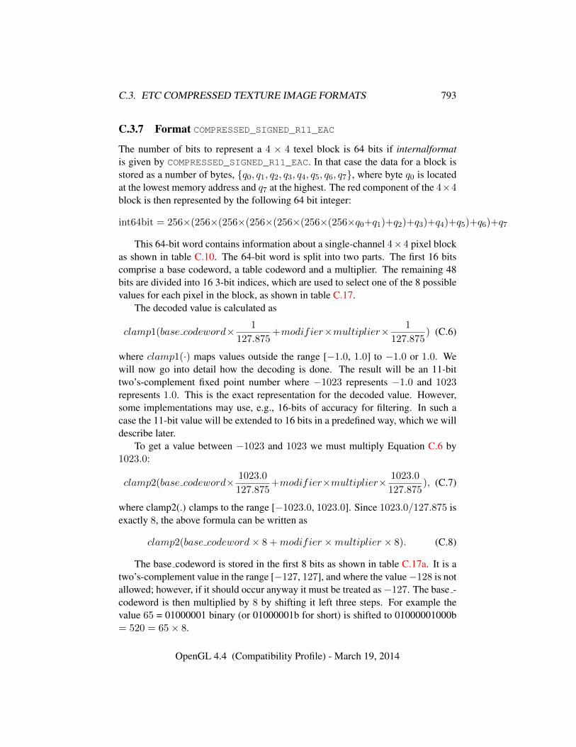
C.3. ETC COMPRESSED TEXTURE IMAGE FORMATS 793
C.3.7 Format COMPRESSED_SIGNED_R11_EAC
The number of bits to represent a 4 × 4 texel block is 64 bits if internalformatis given by COMPRESSED_SIGNED_R11_EAC. In that case the data for a block isstored as a number of bytes, {q0, q1, q2, q3, q4, q5, q6, q7}, where byte q0 is locatedat the lowest memory address and q7 at the highest. The red component of the 4×4block is then represented by the following 64 bit integer:
int64bit = 256×(256×(256×(256×(256×(256×(256×q0+q1)+q2)+q3)+q4)+q5)+q6)+q7
This 64-bit word contains information about a single-channel 4×4 pixel blockas shown in table C.10. The 64-bit word is split into two parts. The first 16 bitscomprise a base codeword, a table codeword and a multiplier. The remaining 48bits are divided into 16 3-bit indices, which are used to select one of the 8 possiblevalues for each pixel in the block, as shown in table C.17.
The decoded value is calculated as
clamp1(base codeword× 1
127.875+modifier×multiplier× 1
127.875) (C.6)
where clamp1(·) maps values outside the range [−1.0, 1.0] to −1.0 or 1.0. Wewill now go into detail how the decoding is done. The result will be an 11-bittwo’s-complement fixed point number where −1023 represents −1.0 and 1023represents 1.0. This is the exact representation for the decoded value. However,some implementations may use, e.g., 16-bits of accuracy for filtering. In such acase the 11-bit value will be extended to 16 bits in a predefined way, which we willdescribe later.
To get a value between −1023 and 1023 we must multiply Equation C.6 by1023.0:
clamp2(base codeword× 1023.0
127.875+modifier×multiplier× 1023.0
127.875), (C.7)
where clamp2(.) clamps to the range [−1023.0, 1023.0]. Since 1023.0/127.875 isexactly 8, the above formula can be written as
clamp2(base codeword× 8 +modifier ×multiplier × 8). (C.8)
The base codeword is stored in the first 8 bits as shown in table C.17a. It is atwo’s-complement value in the range [−127, 127], and where the value−128 is notallowed; however, if it should occur anyway it must be treated as−127. The base -codeword is then multiplied by 8 by shifting it left three steps. For example thevalue 65 = 01000001 binary (or 01000001b for short) is shifted to 01000001000b= 520 = 65× 8.
OpenGL 4.4 (Compatibility Profile) - March 19, 2014
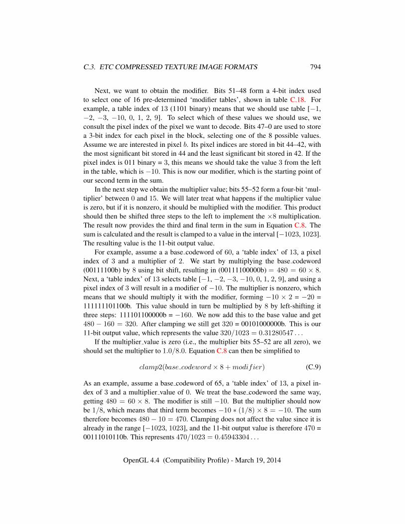
C.3. ETC COMPRESSED TEXTURE IMAGE FORMATS 794
Next, we want to obtain the modifier. Bits 51–48 form a 4-bit index usedto select one of 16 pre-determined ‘modifier tables’, shown in table C.18. Forexample, a table index of 13 (1101 binary) means that we should use table [−1,−2, −3, −10, 0, 1, 2, 9]. To select which of these values we should use, weconsult the pixel index of the pixel we want to decode. Bits 47–0 are used to storea 3-bit index for each pixel in the block, selecting one of the 8 possible values.Assume we are interested in pixel b. Its pixel indices are stored in bit 44–42, withthe most significant bit stored in 44 and the least significant bit stored in 42. If thepixel index is 011 binary = 3, this means we should take the value 3 from the leftin the table, which is −10. This is now our modifier, which is the starting point ofour second term in the sum.
In the next step we obtain the multiplier value; bits 55–52 form a four-bit ‘mul-tiplier’ between 0 and 15. We will later treat what happens if the multiplier valueis zero, but if it is nonzero, it should be multiplied with the modifier. This productshould then be shifted three steps to the left to implement the ×8 multiplication.The result now provides the third and final term in the sum in Equation C.8. Thesum is calculated and the result is clamped to a value in the interval [−1023, 1023].The resulting value is the 11-bit output value.
For example, assume a a base codeword of 60, a ‘table index’ of 13, a pixelindex of 3 and a multiplier of 2. We start by multiplying the base codeword(00111100b) by 8 using bit shift, resulting in (00111100000b) = 480 = 60 × 8.Next, a ‘table index’ of 13 selects table [−1, −2, −3, −10, 0, 1, 2, 9], and using apixel index of 3 will result in a modifier of −10. The multiplier is nonzero, whichmeans that we should multiply it with the modifier, forming −10 × 2 = −20 =111111101100b. This value should in turn be multiplied by 8 by left-shifting itthree steps: 111101100000b = −160. We now add this to the base value and get480 − 160 = 320. After clamping we still get 320 = 00101000000b. This is our11-bit output value, which represents the value 320/1023 = 0.31280547 . . .
If the multiplier value is zero (i.e., the multiplier bits 55–52 are all zero), weshould set the multiplier to 1.0/8.0. Equation C.8 can then be simplified to
clamp2(base codeword× 8 +modifier) (C.9)
As an example, assume a base codeword of 65, a ‘table index’ of 13, a pixel in-dex of 3 and a multiplier value of 0. We treat the base codeword the same way,getting 480 = 60 × 8. The modifier is still −10. But the multiplier should nowbe 1/8, which means that third term becomes −10 ∗ (1/8) × 8 = −10. The sumtherefore becomes 480− 10 = 470. Clamping does not affect the value since it isalready in the range [−1023, 1023], and the 11-bit output value is therefore 470 =00111010110b. This represents 470/1023 = 0.45943304 . . .
OpenGL 4.4 (Compatibility Profile) - March 19, 2014
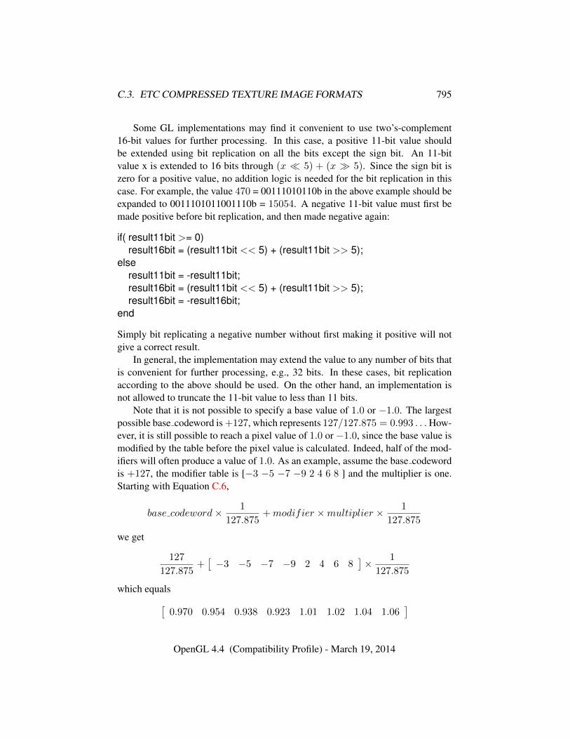
C.3. ETC COMPRESSED TEXTURE IMAGE FORMATS 795
Some GL implementations may find it convenient to use two’s-complement16-bit values for further processing. In this case, a positive 11-bit value shouldbe extended using bit replication on all the bits except the sign bit. An 11-bitvalue x is extended to 16 bits through (x � 5) + (x � 5). Since the sign bit iszero for a positive value, no addition logic is needed for the bit replication in thiscase. For example, the value 470 = 00111010110b in the above example should beexpanded to 0011101011001110b = 15054. A negative 11-bit value must first bemade positive before bit replication, and then made negative again:
if( result11bit >= 0)result16bit = (result11bit << 5) + (result11bit >> 5);
elseresult11bit = -result11bit;result16bit = (result11bit << 5) + (result11bit >> 5);result16bit = -result16bit;
end
Simply bit replicating a negative number without first making it positive will notgive a correct result.
In general, the implementation may extend the value to any number of bits thatis convenient for further processing, e.g., 32 bits. In these cases, bit replicationaccording to the above should be used. On the other hand, an implementation isnot allowed to truncate the 11-bit value to less than 11 bits.
Note that it is not possible to specify a base value of 1.0 or −1.0. The largestpossible base codeword is +127, which represents 127/127.875 = 0.993 . . .How-ever, it is still possible to reach a pixel value of 1.0 or −1.0, since the base value ismodified by the table before the pixel value is calculated. Indeed, half of the mod-ifiers will often produce a value of 1.0. As an example, assume the base codewordis +127, the modifier table is [−3 −5 −7 −9 2 4 6 8 ] and the multiplier is one.Starting with Equation C.6,
base codeword× 1
127.875+modifier ×multiplier × 1
127.875
we get
127
127.875+[−3 −5 −7 −9 2 4 6 8
]× 1
127.875
which equals[0.970 0.954 0.938 0.923 1.01 1.02 1.04 1.06
]OpenGL 4.4 (Compatibility Profile) - March 19, 2014
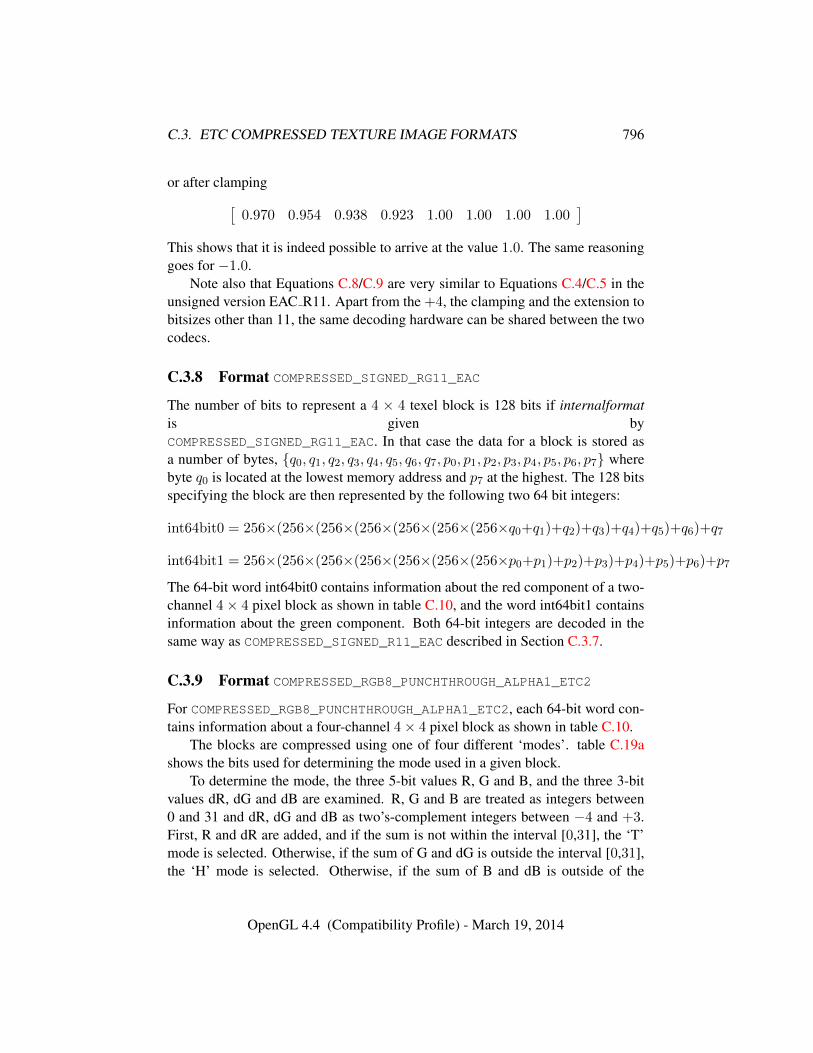
C.3. ETC COMPRESSED TEXTURE IMAGE FORMATS 796
or after clamping[0.970 0.954 0.938 0.923 1.00 1.00 1.00 1.00
]This shows that it is indeed possible to arrive at the value 1.0. The same reasoninggoes for −1.0.
Note also that Equations C.8/C.9 are very similar to Equations C.4/C.5 in theunsigned version EAC R11. Apart from the +4, the clamping and the extension tobitsizes other than 11, the same decoding hardware can be shared between the twocodecs.
C.3.8 Format COMPRESSED_SIGNED_RG11_EAC
The number of bits to represent a 4 × 4 texel block is 128 bits if internalformatis given byCOMPRESSED_SIGNED_RG11_EAC. In that case the data for a block is stored asa number of bytes, {q0, q1, q2, q3, q4, q5, q6, q7, p0, p1, p2, p3, p4, p5, p6, p7} wherebyte q0 is located at the lowest memory address and p7 at the highest. The 128 bitsspecifying the block are then represented by the following two 64 bit integers:
int64bit0 = 256×(256×(256×(256×(256×(256×(256×q0+q1)+q2)+q3)+q4)+q5)+q6)+q7
int64bit1 = 256×(256×(256×(256×(256×(256×(256×p0+p1)+p2)+p3)+p4)+p5)+p6)+p7The 64-bit word int64bit0 contains information about the red component of a two-channel 4× 4 pixel block as shown in table C.10, and the word int64bit1 containsinformation about the green component. Both 64-bit integers are decoded in thesame way as COMPRESSED_SIGNED_R11_EAC described in Section C.3.7.
C.3.9 Format COMPRESSED_RGB8_PUNCHTHROUGH_ALPHA1_ETC2
For COMPRESSED_RGB8_PUNCHTHROUGH_ALPHA1_ETC2, each 64-bit word con-tains information about a four-channel 4× 4 pixel block as shown in table C.10.
The blocks are compressed using one of four different ‘modes’. table C.19ashows the bits used for determining the mode used in a given block.
To determine the mode, the three 5-bit values R, G and B, and the three 3-bitvalues dR, dG and dB are examined. R, G and B are treated as integers between0 and 31 and dR, dG and dB as two’s-complement integers between −4 and +3.First, R and dR are added, and if the sum is not within the interval [0,31], the ‘T’mode is selected. Otherwise, if the sum of G and dG is outside the interval [0,31],the ‘H’ mode is selected. Otherwise, if the sum of B and dB is outside of the
OpenGL 4.4 (Compatibility Profile) - March 19, 2014
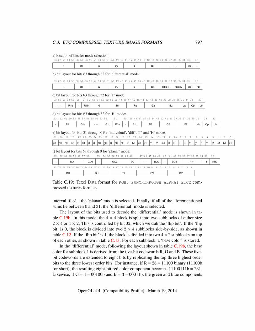
C.3. ETC COMPRESSED TEXTURE IMAGE FORMATS 797
a) location of bits for mode selection:63 62 61 60 59 58 57 56 55 54 53 52 51 50 49 48 47 46 45 44 43 42 41 40 39 38 37 36 35 34 33 32
R dR G dG B dB - - - - - - Op -
b) bit layout for bits 63 through 32 for ’differential’ mode:
63 62 61 60 59 58 57 56 55 54 53 52 51 50 49 48 47 46 45 44 43 42 41 40 39 38 37 36 35 34 33 32
R dR G dG B dB table1 table2 Op FB
c) bit layout for bits 63 through 32 for ’T’ mode:63 62 61 60 59 58 57 56 55 54 53 52 51 50 49 48 47 46 45 44 43 42 41 40 39 38 37 36 35 34 33 32
- - - R1a - R1b G1 B1 R2 G2 B2 da Op db
d) bit layout for bits 63 through 32 for ’H’ mode:63 62 61 60 59 58 57 56 55 54 53 52 51 50 49 48 47 46 45 44 43 42 41 40 39 38 37 36 35 34 33 32
- R1 G1a - - - G1b B1a - B1b R2 G2 B2 da Op db
e) bit layout for bits 31 through 0 for ’individual’, ’diff’, ’T’ and ’H’ modes:31 30 29 28 27 26 25 24 23 22 21 20 19 18 17 16 15 14 13 12 11 10 9 8 7 6 5 4 3 2 1 0
p0 o0 n0 m0 l0 k0 j0 i0 h0 g0 f0 e0 d0 c0 b0 a0 p1 o1 n1 m1 l1 k1 j1 i1 h1 g1 f1 e1 d1 c1 b1 a1
f) bit layout for bits 63 through 0 for ’planar’ mode:63 62 61 60 59 58 57 56 55 54 53 52 51 50 49 48 47 46 45 44 43 42 41 40 39 38 37 36 35 34 33 32
- RO GO1 - GO2 BO1 - - - BO2 - BO3 RH1 1 RH2
31 30 29 28 27 26 25 24 23 22 21 20 19 18 17 16 15 14 13 12 11 10 9 8 7 6 5 4 3 2 1 0
GH BH RV GV BV
Table C.19: Texel Data format for RGB8_PUNCHTHROUGH_ALPHA1_ETC2 com-pressed textures formats
interval [0,31], the ‘planar’ mode is selected. Finally, if all of the aforementionedsums lie between 0 and 31, the ‘differential’ mode is selected.
The layout of the bits used to decode the ‘differential’ mode is shown in ta-ble C.19b. In this mode, the 4 × 4 block is split into two subblocks of either size2× 4 or 4× 2. This is controlled by bit 32, which we dub the ‘flip bit’. If the ‘flipbit’ is 0, the block is divided into two 2 × 4 subblocks side-by-side, as shown intable C.12. If the ‘flip bit’ is 1, the block is divided into two 4×2 subblocks on topof each other, as shown in table C.13. For each subblock, a ‘base color’ is stored.
In the ‘differential’ mode, following the layout shown in table C.19b, the basecolor for subblock 1 is derived from the five-bit codewords R, G and B. These five-bit codewords are extended to eight bits by replicating the top three highest orderbits to the three lowest order bits. For instance, if R = 28 = 11100 binary (11100bfor short), the resulting eight-bit red color component becomes 11100111b = 231.Likewise, if G = 4 = 00100b and B = 3 = 00011b, the green and blue components
OpenGL 4.4 (Compatibility Profile) - March 19, 2014
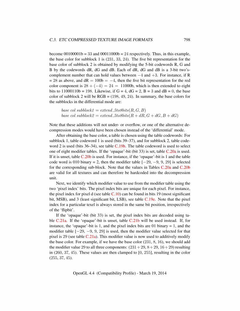
C.3. ETC COMPRESSED TEXTURE IMAGE FORMATS 798
become 00100001b = 33 and 00011000b = 24 respectively. Thus, in this example,the base color for subblock 1 is (231, 33, 24). The five bit representation for thebase color of subblock 2 is obtained by modifying the 5-bit codewords R, G andB by the codewords dR, dG and dB. Each of dR, dG and dB is a 3-bit two’s-complement number that can hold values between −4 and +3. For instance, if R= 28 as above, and dR = 100b = −4, then the five bit representation for the redcolor component is 28 + (−4) = 24 = 11000b, which is then extended to eightbits to 11000110b = 198. Likewise, if G = 4, dG = 2, B = 3 and dB = 0, the basecolor of subblock 2 will be RGB = (198, 49, 24). In summary, the base colors forthe subblocks in the differential mode are:
base col subblock1 = extend 5to8bits(R,G,B)base col subblock2 = extend 5to8bits(R+ dR,G+ dG,B + dG)
Note that these additions will not under- or overflow, or one of the alternative de-compression modes would have been chosen instead of the ‘differential’ mode.
After obtaining the base color, a table is chosen using the table codewords: Forsubblock 1, table codeword 1 is used (bits 39–37), and for subblock 2, table code-word 2 is used (bits 36–34), see table C.19b. The table codeword is used to selectone of eight modifier tables. If the ‘opaque’-bit (bit 33) is set, table C.20a is used.If it is unset, table C.20b is used. For instance, if the ‘opaque’-bit is 1 and the tablecode word is 010 binary = 2, then the modifier table [−29, −9, 9, 29] is selectedfor the corresponding sub-block. Note that the values in Tables C.20a and C.20bare valid for all textures and can therefore be hardcoded into the decompressionunit.
Next, we identify which modifier value to use from the modifier table using thetwo ‘pixel index’ bits. The pixel index bits are unique for each pixel. For instance,the pixel index for pixel d (see table C.10) can be found in bits 19 (most significantbit, MSB), and 3 (least significant bit, LSB), see table C.19e. Note that the pixelindex for a particular texel is always stored in the same bit position, irrespectivelyof the ‘flipbit’.
If the ‘opaque’-bit (bit 33) is set, the pixel index bits are decoded using ta-ble C.21a. If the ‘opaque’-bit is unset, table C.21b will be used instead. If, forinstance, the ‘opaque’-bit is 1, and the pixel index bits are 01 binary = 1, and themodifier table [−29, −9, 9, 29] is used, then the modifier value selected for thatpixel is 29 (see table C.21a). This modifier value is now used to additively modifythe base color. For example, if we have the base color (231, 8, 16), we should addthe modifier value 29 to all three components: (231+29, 8+29, 16+29) resultingin (260, 37, 45). These values are then clamped to [0, 255], resulting in the color(255, 37, 45).
OpenGL 4.4 (Compatibility Profile) - March 19, 2014
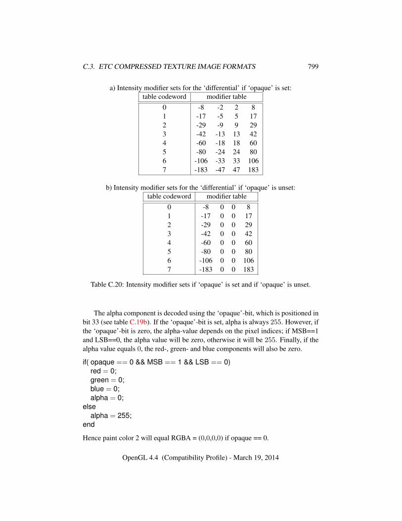
C.3. ETC COMPRESSED TEXTURE IMAGE FORMATS 799
a) Intensity modifier sets for the ‘differential’ if ‘opaque’ is set:table codeword modifier table
0 -8 -2 2 81 -17 -5 5 172 -29 -9 9 293 -42 -13 13 424 -60 -18 18 605 -80 -24 24 806 -106 -33 33 1067 -183 -47 47 183
b) Intensity modifier sets for the ‘differential’ if ‘opaque’ is unset:table codeword modifier table
0 -8 0 0 81 -17 0 0 172 -29 0 0 293 -42 0 0 424 -60 0 0 605 -80 0 0 806 -106 0 0 1067 -183 0 0 183
Table C.20: Intensity modifier sets if ‘opaque’ is set and if ‘opaque’ is unset.
The alpha component is decoded using the ‘opaque’-bit, which is positioned inbit 33 (see table C.19b). If the ‘opaque’-bit is set, alpha is always 255. However, ifthe ‘opaque’-bit is zero, the alpha-value depends on the pixel indices; if MSB==1and LSB==0, the alpha value will be zero, otherwise it will be 255. Finally, if thealpha value equals 0, the red-, green- and blue components will also be zero.
if( opaque == 0 && MSB == 1 && LSB == 0)red = 0;green = 0;blue = 0;alpha = 0;
elsealpha = 255;
end
Hence paint color 2 will equal RGBA = (0,0,0,0) if opaque == 0.
OpenGL 4.4 (Compatibility Profile) - March 19, 2014
C.3. ETC COMPRESSED TEXTURE IMAGE FORMATS 800
a) Mapping from pixel index values to modifier values when ‘opaque’-bit is set.pixel index value resulting modifier valuemsb lsb
1 1 -b (large negative value)1 0 -a (small negative value)0 0 a (small positive value)0 1 b (large positive value)
b) Mapping from pixel index values to modifier values when ‘opaque’-bit is unset.pixel index value resulting modifier valuemsb lsb
1 1 -b (large negative value)1 0 0 (zero)0 0 0 (zero)0 1 b (large positive value)
Table C.21: Mapping from pixel index values to modifier values forCOMPRESSED_RGB8_PUNCHTHROUGH_ALPHA1_ETC2 compressed textures
In the example above, assume that the ‘opaque’-bit was instead 0. Then, sincethe MSB = 0 and LSB 1, alpha will be 255, and the final decoded RGBA-tuple willbe (255, 37, 45, 255).
The ‘T’ and ‘H’ compression modes share some characteristics: both use twobase colors stored using 4 bits per channel. These bits are not stored sequentially,but in the layout shown in Tables C.19c and C.19d. To clarify, in the ‘T’ mode,the two colors are constructed as follows:
base col 1 = extend 4to8bits( (R1a� 2) |R1b, G1, B1)base col 2 = extend 4to8bits(R2, G2, B2)
In the ‘H’ mode, the two colors are constructed as follows:
base col 1 = extend 4to8bits(R1, (G1a� 1) |G1b, (B1a� 3) |B1b)base col 2 = extend 4to8bits(R2, G2, B2)
The function extend 4to8bits() just replicates the four bits twice. This is equivalentto multiplying by 17. As an example, extend 4to8bits(1101b) equals 11011101b =221.
Both the ‘T’ and ‘H’ modes have four ‘paint colors’ which are the colors thatwill be used in the decompressed block, but they are assigned in a different manner.
OpenGL 4.4 (Compatibility Profile) - March 19, 2014
C.3. ETC COMPRESSED TEXTURE IMAGE FORMATS 801
In the ‘T’ mode, ‘paint color 0’ is simply the first base color, and ‘paint color 2’is the second base color. To obtain the other ‘paint colors’, a ‘distance’ is firstdetermined, which will be used to modify the luminance of one of the base colors.This is done by combining the values ‘da’ and ‘db’ shown in table C.19c by (da�1)|db, and then using this value as an index into the small look-up table shown intable C.16. For example, if ‘da’ is 10 binary and ‘db’ is 1 binary, the index is 101binary and the selected distance will be 32. ‘Paint color 1’ is then equal to thesecond base color with the ‘distance’ added to each channel, and ‘paint color 3’ isthe second base color with the ‘distance’ subtracted. In summary, to determine thefour ‘paint colors’ for a ‘T’ block:
paint color 0 = base col 1paint color 1 = base col 2 + (d, d, d)paint color 2 = base col 2paint color 3 = base col 2 − (d, d, d)
In both cases, the value of each channel is clamped to within [0,255].Just as for the differential mode, the RGB channels are set to zero if alpha is
zero, and the alpha component is caluclated the same way:
if( opaque == 0 && MSB == 1 && LSB == 0)red = 0;green = 0;blue = 0;alpha = 0;
elsealpha = 255;
end
A ‘distance’ value is computed for the ‘H’ mode as well, but doing so is slightlymore complex. In order to construct the three-bit index into the distance tableshown in table C.16, ‘da’ and ‘db’ shown in table C.19d are used as the mostsignificant bit and middle bit, respectively, but the least significant bit is computedas (base col 1 value ≥ base col 2 value), the ‘value’ of a color for the comparisonbeing equal to (R � 16) + (G � 8) + B. Once the ‘distance’ d has beendetermined for an ‘H’ block, the four ‘paint colors’ will be:
paint color 0 = base col 1 + (d, d, d)paint color 1 = base col 1 − (d, d, d)paint color 2 = base col 2 + (d, d, d)paint color 3 = base col 2 − (d, d, d)
OpenGL 4.4 (Compatibility Profile) - March 19, 2014
C.3. ETC COMPRESSED TEXTURE IMAGE FORMATS 802
Yet again, RGB is zeroed if alpha is 0 and the alpha component is determined thesame way:
if( opaque == 0 && MSB == 1 && LSB == 0)red = 0;green = 0;blue = 0;alpha = 0;
elsealpha = 255;
end
Hence paint color 2 will have R=G=B=alpha=0 if opaque == 0.Again, all color components are clamped to within [0,255]. Finally, in both
the ‘T’ and ‘H’ modes, every pixel is assigned one of the four ‘paint colors’ in thesame way the four modifier values are distributed in ‘individual’ or ‘differential’blocks. For example, to choose a paint color for pixel d, an index is constructedusing bit 19 as most significant bit and bit 3 as least significant bit. Then, if a pixelhas index 2, for example, it will be assigned paint color 2.
The final mode possible in an COMPRESSED_RGB8_PUNCHTHROUGH_-
ALPHA1_ETC2- compressed block is the ‘planar’ mode. In this mode, the‘opaque’-bit must be 1 (a valid encoder should not produce an ‘opaque’-bit equal to0 in the planar mode), but should the ‘opaque’-bit anyway be 0 the decoder shouldtreat it as if it were 1. In the ‘planar’ mode, three base colors are supplied and usedto form a color plane used to determine the color of the individual pixels in theblock.
All three base colors are stored in RGB 676 format, and stored in the mannershown in table C.19f. The three colors are there labelled ‘O’, ‘H’ and ‘V’, so thatthe three components of color ‘V’ are RV, GV and BV, for example. Some colorchannels are split into non-consecutive bit-ranges, for example BO is reconstructedusing BO1 as the most significant bit, BO2 as the two following bits, and BO3 asthe three least significant bits.
Once the bits for the base colors have been extracted, they must be extendedto 8 bits per channel in a manner analogous to the method used for the base colorsin other modes. For example, the 6-bit blue and red channels are extended byreplicating the two most significant of the six bits to the two least significant of thefinal 8 bits.
With three base colors in RGB888 format, the color of each pixel can then bedetermined as:
OpenGL 4.4 (Compatibility Profile) - March 19, 2014
C.3. ETC COMPRESSED TEXTURE IMAGE FORMATS 803
R(x, y) = x× (RH −RO)/4.0 + y × (RV −RO)/4.0 +ROG(x, y) = x× (GH −GO)/4.0 + y × (GV −GO)/4.0 +GOB(x, y) = x× (BH −BO)/4.0 + y × (BV −BO)/4.0 +BOA(x, y) = 255,
where x and y are values from 0 to 3 corresponding to the pixels coordinates withinthe block, x being in the u direction and y in the v direction. For example, the pixelg in table C.10 would have x = 1 and y = 2.
These values are then rounded to the nearest integer (to the larger integer ifthere is a tie) and then clamped to a value between 0 and 255. Note that this isequivalent to
R(x, y) = clamp255((x× (RH −RO) + y × (RV −RO) + 4×RO + 2)� 2)G(x, y) = clamp255((x× (GH −GO) + y × (GV −GO) + 4×GO + 2)� 2)B(x, y) = clamp255((x× (BH −BO) + y × (BV −BO) + 4×BO + 2)� 2)A(x, y) = 255,
where clamp255 clamps the value to a number in the range [0, 255].Note that the alpha component is always 255 in the planar mode.This specification gives the output for each compression mode in 8-bit integer
colors between 0 and 255, and these values all need to be divided by 255 for thefinal floating point representation.
C.3.10 Format COMPRESSED_SRGB8_PUNCHTHROUGH_ALPHA1_ETC2
Decompression of floating point sRGB values in COMPRESSED_SRGB8_-
PUNCHTHROUGH_ALPHA1_ETC2 follows that of floating point RGB values ofCOMPRESSED_RGB8_PUNCHTHROUGH_ALPHA1_ETC2. The result is sRGB valuesbetween 0.0 and 1.0. The further conversion from an sRGB encoded component,cs, to a linear component, cl, is as described in section 8.24. Assume cs is thesRGB component in the range [0,1]. Note that the alpha component is not gammacorrected, and hence does not use the above formula.
OpenGL 4.4 (Compatibility Profile) - March 19, 2014

Appendix D
Profiles and the DeprecationModel
OpenGL 3.0 introduced a deprecation model in which certain features are markedas deprecated. Deprecated features are expected to be completely removed from afuture version of OpenGL. Deprecated features are summarized in section D.2.
To aid developers in writing applications which will run on such future ver-sions, it is possible to create an OpenGL context which does not support depre-cated features. Such a context is called a forward compatible context, while acontext supporting all OpenGL features is called a full context. Forward compat-ible contexts cannot restore deprecated functionality through extensions, but theymay support additional, non-deprecated functionality through extensions.
Profiles define subsets of OpenGL functionality targeted to specific applicationdomains. Starting with OpenGL 3.2, two profiles are defined (see below). Futureversions may define additional profiles addressing embedded systems or other do-mains. OpenGL implementations are not required to support all defined profiles,but must support the core profile described below.
To enable application control of deprecation and profiles, new context creationAPIs have been defined as extensions to GLX, WGL and EGL. These APIs allowspecifying a particular version, profile, and full or forward compatible status, andwill either create a context compatible with the request, or fail (if, for example,requesting an OpenGL version or profile not supported by the implementation),
Only the ARB may define OpenGL profiles and deprecated features.
804
D.1. CORE AND COMPATIBILITY PROFILES 805
D.1 Core and Compatibility Profiles
The core profile of OpenGL defines essential functionality for the modern pro-grammable shading model introduced in OpenGL 2.0, but does not include featuresmarked as removed for that version of the Specification (see section D.2).
The compatibility profile does not remove any functionality.It is not possible to implement both core and compatibility profiles in a single
GL context, since the core profile mandates functional restrictions not present in thecompatibility profile. Refer to the WGL_ARB_create_context_profile andGLX_ARB_create_context_profile extensions (see appendix H.3.3.66) forinformation on creating a context implementing a specific profile.
D.2 Deprecated and Removed Features
OpenGL 3.0 defined a set of deprecated features. OpenGL 3.1 removed most of thedeprecated features and moved them into the optional GL_ARB_compatibilityextension. The OpenGL 3.2 core profile removes the same features as OpenGL3.1, while the optional compatibility profile supports all those features.
Deprecated and removed features are summarized below in two groups: fea-tures which are marked deprecated by the core profile, but have not yet been re-moved, and features actually removed from the core profile of the current versionof OpenGL (no features have been removed from or deprecated in the compatibilityprofile).
Functions which have been removed will generate an INVALID_OPERATION
error if called in the core profile or in a forward-compatible context. Functionswhich are partially removed (e.g. no longer accept some parameter values) willgenerate the errors appropriate for any other unrecognized value of that parame-ter when a removed parameter value is passed in the core profile or a forward-compatible context. Functions which are deprecated but have not yet been removedfrom the core profile continue to operate normally except in a forward-compatiblecontext, where they are also removed.
D.2.1 Deprecated But Still Supported Features
The following features are deprecated, but still present in the core profile. Theymay be removed from a future version of OpenGL, and are removed in a forward-compatible context implementing the core profile.
• Wide lines - LineWidth values greater than 1.0 will generate an INVALID_-VALUE error.
OpenGL 4.4 (Compatibility Profile) - March 19, 2014
D.2. DEPRECATED AND REMOVED FEATURES 806
• Global component limit query - the implementation-dependent valuesMAX_VARYING_COMPONENTS and MAX_VARYING_FLOATS.
• The query targets NUM_COMPRESSED_TEXTURE_FORMATS andCOMPRESSED_TEXTURE_FORMATS (see section 8.5).
• Bitmap pack/unpack state for bitmaps - the pixel pack parameters UNPACK_-LSB_FIRST and PACK_LSB_FIRST.
D.2.2 Removed Features
• Application-generated object names - the names of all object types, such asbuffer, query, and texture objects, must be generated using the correspond-ing Gen* commands. Trying to bind an object name not returned by a Gen*command will result in an INVALID_OPERATION error. This behavior is al-ready the case for framebuffer, renderbuffer, and vertex array objects. Objecttypes which have default objects (objects named zero), such as vertex ar-ray, framebuffer, and texture objects, may also bind the default object, eventhough it is not returned by Gen*.
• Color index mode - No color index visuals are supplied by the windowsystem-binding APIs such as GLX and WGL, so the default framebufferis always in RGBA mode. All language and state related to color indexmode vertex, rasterization, and fragment processing behavior is removed.COLOR_INDEX formats are also deprecated.
• OpenGL Shading Language versions 1.10 and 1.20. These versions of theshading language depend on many API features that have also been depre-cated.
• Begin / End primitive specification - Begin, End, and EdgeFlag* (sec-tion 10.8); Color*, FogCoord*, Index*, Normal3*, SecondaryColor3*,TexCoord*, Vertex* (section 10.2); and all associated state in tables 23.2and 23.3. Vertex arrays and array drawing commands must be used to drawprimitives. However, VertexAttrib* and the current vertex attribute stateare retained in order to provide default attribute values for disabled attributearrays.
• Edge flags and fixed-function vertex processing - ColorPointer, EdgeFlag-Pointer, FogCoordPointer, IndexPointer, NormalPointer, Secondary-ColorPointer, TexCoordPointer, VertexPointer, EnableClientState,
OpenGL 4.4 (Compatibility Profile) - March 19, 2014
D.2. DEPRECATED AND REMOVED FEATURES 807
DisableClientState, and InterleavedArrays, ClientActiveTexture (sec-tion 10.3); Frustum, LoadIdentity, LoadMatrix, LoadTransposeMa-trix, MatrixMode, MultMatrix, MultTransposeMatrix, Ortho, PopMa-trix, PushMatrix, Rotate, Scale, and Translate (section 12.1.1; En-able/Disable targets RESCALE_NORMAL and NORMALIZE (section 12.1.2);
TexGen* and Enable/Disable targets TEXTURE_GEN_* (section 12.1.3,Material*, Light*, LightModel*, and ColorMaterial, ShadeModel,
and Enable/Disable targets LIGHTING. VERTEX_PROGRAM_TWO_SIDE,LIGHTi, and COLOR_MATERIAL (sections 12.2.2 and 12.2.3; ClipPlane;and all associated fixed-function vertex array, multitexture, matrix and ma-trix stack, normal and texture coordinate, lighting, and clipping state. Avertex shader must be defined in order to draw primitives.
Language referring to edge flags in the current specification is modified asthough all edge flags are TRUE.
Note that the FrontFace and ClampColor commands in section 12.2 are notdeprecated, as they still affect other non-deprecated functionality; however,the ClampColor targets CLAMP_VERTEX_COLOR and CLAMP_FRAGMENT_-COLOR are deprecated.
• Client vertex and index arrays - all vertex array attribute and element arrayindex pointers must refer to buffer objects (section 10.3.8). The defaultvertex array object (the name zero) is also deprecated. Calling VertexAt-tribPointer when no buffer object or no vertex array object is bound willgenerate an INVALID_OPERATION error, as will calling any array drawingcommand when no vertex array object is bound.
• Rectangles - Rect* (section 10.9).
• Current raster position - RasterPos* and WindowPos* (section 14.7), andall associated state.
• Two-sided color selection (section 12.2.1.1) - Enable target VERTEX_-PROGRAM_TWO_SIDE; OpenGL Shading Language built-ins gl_-
BackColor and gl_BackSecondaryColor; and all associated state.
• Non-sprite points (section 14.4) - Enable/Disable targets POINT_SMOOTHand POINT_SPRITE, and all associated state. Point rasterization is alwaysperformed as though POINT_SPRITE were enabled.
• Wide lines and line stipple - LineWidth is not deprecated, but values greaterthan 1.0 will generate an INVALID_VALUE error; LineStipple and En-able/Disable target LINE_STIPPLE (section 14.5.2, and all associated state.
OpenGL 4.4 (Compatibility Profile) - March 19, 2014
D.2. DEPRECATED AND REMOVED FEATURES 808
• Quadrilateral and polygon primitives - vertex array drawing modesPOLYGON, QUADS, and QUAD_STRIP (section 10.8, related descriptions ofrasterization of non-triangle polygons in section 14.6, and all associatedstate.
• Separate polygon draw mode - PolygonMode face values of FRONT andBACK; polygons are always drawn in the same mode, no matter which faceis being rasterized.
• Polygon Stipple - PolygonStipple and Enable/Disable target POLYGON_-STIPPLE (section 14.6.2), and all associated state.
• Pixel transfer modes and operations - all pixel transfer modes, includingpixel maps, shift and bias, color table lookup, color matrix, and convolutioncommands and state (sections 8.4.2, 8.4.3, and 8.4.5), and all associatedstate and commands defining that state.
• Pixel drawing - DrawPixels and PixelZoom (section 18.1). However, thelanguage describing pixel rectangles in section 8.4 is retained as it is requiredfor TexImage* and ReadPixels.
• Bitmaps - Bitmap (section 14.8) and the BITMAP external format.
• Legacy OpenGL 1.0 pixel formats - the values 1, 2, 3, and 4 are no longeraccepted as internal formats by TexImage* or any other command taking aninternal format argument. The initial internal format of a texel array is RGBAinstead of 1 (see section 8.22). TEXTURE_COMPONENTS is deprecated;always use TEXTURE_INTERNAL_FORMAT.
• Legacy pixel formats - all ALPHA, LUMINANCE, LUMINANCE_ALPHA, andINTENSITY external and internal formats, including compressed, floating-point, and integer variants (see tables 8.8, 8.18, 8.20, 8.22, 16.1, and 8.25);all references to luminance and intensity formats elsewhere in the specifi-
cation, including conversion to and from those formats; and all associatedstate. including state describing the allocation or format of luminance andintensity texture or framebuffer components.
• Depth texture mode - DEPTH_TEXTURE_MODE. Section 8.23.1 is to bechanged so that r is returned to texture samplers directly, and the OpenGLShading Language 1.30 Specification is to be changed so that (r, 0, 0, 1) isalways returned from depth texture samplers in this case.
OpenGL 4.4 (Compatibility Profile) - March 19, 2014
D.2. DEPRECATED AND REMOVED FEATURES 809
• Texture wrap mode CLAMP - CLAMP is no longer accepted as a value oftexture parameters TEXTURE_WRAP_S, TEXTURE_WRAP_T, or TEXTURE_-WRAP_R.
• Texture borders - the border value to TexImage* must always be zero, or anINVALID_VALUE error is generated (section 8.5); all language in section 8referring to nonzero border widths during texture image specification andtexture sampling; and all associated state.
• Automatic mipmap generation - TexParameter* target GENERATE_MIPMAP(section 8.14.5), and all associated state.
• Fixed-function fragment processing - AreTexturesResident, Prioritize-Textures, and TexParameter target TEXTURE_PRIORITY; TexEnv targetTEXTURE_ENV, and all associated parameters; TexEnv target TEXTURE_-FILTER_CONTROL, and parameter name TEXTURE_LOD_BIAS; Enable tar-gets of all dimensionalities (TEXTURE_1D, TEXTURE_2D, TEXTURE_3D,TEXTURE_1D_ARRAY, TEXTURE_2D_ARRAY, and TEXTURE_CUBE_MAP);Enable target COLOR_SUM; Enable target FOG, Fog, and all associated pa-rameters; the implementation-dependent values MAX_TEXTURE_UNITS andMAX_TEXTURE_COORDS; and all associated state.
• Alpha test - AlphaFunc and Enable/Disable target ALPHA_TEST (sec-tion 17.3.4), and all associated state.
• Accumulation buffers - ClearAccum, and ACCUM_BUFFER_BIT is not validas a bit in the argument to Clear (section 17.4.3); Accum (section 17.4.5);the ACCUM_*_BITS framebuffer state describing the size of accumulation
buffer components (table 23.85); and all associated state.
Window system-binding APIs such as GLX and WGL may choose to eithernot expose window configs containing accumulation buffers, or to ignoreaccumulation buffers when the default framebuffer bound to a GL contextcontains them.
• Pixel copying - CopyPixels (the comments also applying to CopyTexImagewill be moved to section 8.6).
• Auxiliary color buffers, including AUXi targets of the default framebuffer.
• Context framebuffer size queries - RED_BITS, GREEN_BITS, BLUE_BITS,ALPHA_BITS, DEPTH_BITS, and STENCIL_BITS.
OpenGL 4.4 (Compatibility Profile) - March 19, 2014
D.2. DEPRECATED AND REMOVED FEATURES 810
• Evaluators - Map*, EvalCoord*, MapGrid*, EvalMesh*, EvalPoint*, andall evaluator map enables in table 21.1 (section 21.1, and all associated state.
• Selection and feedback modes - RenderMode, InitNames, PopName,PushName, LoadName, and SelectBuffer (section 21.2); FeedbackBufferand PassThrough (section 21.3); and all associated state.
• Display lists - NewList, EndList, CallList, CallLists, ListBase, GenLists,IsList, and DeleteLists (section 21.4); all references to display lists andbehavior when compiling commands into display lists elsewhere in the spec-ification; and all associated state.
• Hints - the PERSPECTIVE_CORRECTION_HINT, POINT_SMOOTH_HINT,FOG_HINT, and GENERATE_MIPMAP_HINT targets to Hint (section 21.5).
• Attribute stacks - PushAttrib, PushClientAttrib, PopAttrib, Pop-ClientAttrib, the MAX_ATTRIB_STACK_DEPTH, MAX_CLIENT_ATTRIB_-STACK_DEPTH, ATTRIB_STACK_DEPTH, and CLIENT_ATTRIB_STACK_-
DEPTH state, the client and server attribute stacks, and the values ALL_-
ATTRIB_BITS and CLIENT_ALL_ATTRIB_BITS (section 21.6).
• Unified extension string - EXTENSIONS target to GetString (section 22.2).
• Token names and queries - all token names and queries not otherwise men-tioned above for deprecated state, as well as all query entry points whereall valid targets of that query are deprecated state (chapter 22 and the statetables)
OpenGL 4.4 (Compatibility Profile) - March 19, 2014
Appendix E
Version 4.2
OpenGL version 4.2, released on August 8, 2011, is the fourteenth revision sincethe original version 1.0.
Separate versions of the OpenGL 4.2 Specification exist for the core and com-patibility profiles described in appendix D, respectively subtitled the “Core Profile”and the “Compatibility Profile”. This document describes the Compatibility Pro-file. An OpenGL 4.2 implementation must be able to create a context supportingthe core profile, and may also be able to create a context supporting the compati-bility profile.
Material specific to the compatibility profile specification is marked in a dis-tinct color to clearly call out differences between the two profiles.
The OpenGL 4.2 compatibility and core profiles are upward compatible withthe OpenGL 4.1 compatibility and core profiles, respectively.
Following are brief descriptions of changes and additions to OpenGL 4.2.
E.1 New Features
New features in OpenGL 4.2, including the extension or extensions if any on whichthey were based, include:
• Support for BPTC compressed textures (ARB_texture_compression_-bptc).
• Allow pixel storage parameters to affect packing and unpacking of com-pressed textures (ARB_compressed_texture_pixel_storage).
• Shader atomic counters (ARB_shader_atomic_counters).
• Immutable texture images (ARB_texture_storage).
811
E.2. DEPRECATION MODEL 812
• Instanced transformed feedback drawing (ARB_transform_feedback_-instanced).
• Allow the offset within buffer objects used for instanced rendering to bespecified (ARB_base_instance).
• OpenGL Shading Language built-in functions allowing loads from andstores to texture images from any shader stage, and application controlover the ordering of image load/store operations relative to other OpenGLpipeline operations accessing the same memory (ARB_shader_image_-load_store).
• New OpenGL Shading Language features with no OpenGL API impact(ARB_conservative_depth and ARB_shading_language_420pack -see the OpenGL Shading Language Specification for details).
• Queries for sample counts available for a given internal format and usage(ARB_internalformat_query).
• More restrictive alignment constraints for mapped buffers (ARB_map_-buffer_alignment).
E.2 Deprecation Model
The following features are newly deprecated by the OpenGL 4.2 core profile:
• The query targets NUM_COMPRESSED_TEXTURE_FORMATS andCOMPRESSED_TEXTURE_FORMATS (see section 8.5).
Features deprecated by OpenGL 4.1 remain deprecated, but have not yet beenremoved.
E.3 Changed Tokens
New token names are introduced to be used in place of old, less general names.However, the old token names continue to be supported, for backwards compati-bility with code written for previous versions of OpenGL. The new names, and theold names they replace, are shown in table E.1. Note that COPY_READ_BUFFERand COPY_WRITE_BUFFER continue to be used as buffer targets for e.g. Bind-Buffer; the _BINDING forms are used only when querying the buffer object boundto those targets.
OpenGL 4.4 (Compatibility Profile) - March 19, 2014
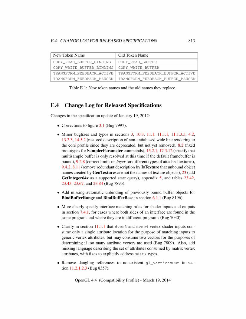
E.4. CHANGE LOG FOR RELEASED SPECIFICATIONS 813
New Token Name Old Token NameCOPY_READ_BUFFER_BINDING COPY_READ_BUFFER
COPY_WRITE_BUFFER_BINDING COPY_WRITE_BUFFER
TRANSFORM_FEEDBACK_ACTIVE TRANSFORM_FEEDBACK_BUFFER_ACTIVE
TRANSFORM_FEEDBACK_PAUSED TRANSFORM_FEEDBACK_BUFFER_PAUSED
Table E.1: New token names and the old names they replace.
E.4 Change Log for Released Specifications
Changes in the specification update of January 19, 2012:
• Corrections to figure 3.1 (Bug 7997).
• Minor bugfixes and typos in sections 3, 10.3, 11.1, 11.1.1, 11.1.3.5, 4.2,13.2.3, 14.5.2 (restored description of non-antialiased wide line rendering tothe core profile since they are deprecated, but not yet removed), 8.2 (fixedprototypes for SamplerParameter commands), 15.2.1, 17.3.12 (specify thatmultisample buffer is only resolved at this time if the default framebuffer isbound), 9.2.8 (correct limits on layer for different types of attached textures),9.4.2, 8.11 (remove redundant description by IsTexture that unbound objectnames created by GenTextures are not the names of texture objects), 23 (addGetInteger64v as a supported state query), appendix 5, and tables 23.42,23.43, 23.67, and 23.84 (Bug 7895).
• Add missing automatic unbinding of previously bound buffer objects forBindBufferRange and BindBufferBase in section 6.1.1 (Bug 8196).
• More clearly specify interface matching rules for shader inputs and outputsin section 7.4.1, for cases where both sides of an interface are found in thesame program and where they are in different programs (Bug 7030).
• Clarify in section 11.1.1 that dvec3 and dvec4 vertex shader inputs con-sume only a single attribute location for the purpose of matching inputs togeneric vertex attributes, but may consume two vectors for the purposes ofdetermining if too many attribute vectors are used (Bug 7809). Also, addmissing language describing the set of attributes consumed by matrix vertexattributes, with fixes to explicitly address dmat* types.
• Remove dangling references to nonexistent gl_VerticesOut in sec-tion 11.2.1.2.3 (Bug 8357).
OpenGL 4.4 (Compatibility Profile) - March 19, 2014
E.4. CHANGE LOG FOR RELEASED SPECIFICATIONS 814
• Fix names of cube map sampler type tokens in table 7.3 (Bug 8303).
• Fix behavior of DeleteTransformFeedbacks in section 13.2.1 to generatean error if any of the objects being deleted has transform feedback active(Bug 8323).
• Remove ambiguity in the order of operations and which vertices are ap-pended by transform feedback when it is resumed in section 13.2.2 (Bug8202).
• Updated description of errors resulting from specifying texture images oflevel 1 or greater which exceed implementation-dependent limits, in sec-tions 8.5 and 8.17.3 (Bug 8210).
• Remove clamping of Dt and Dref prior to depth texture comparison in sec-tion 8.23.1, since it doesn’t reflect hardware reality (Bug 7975).
• Update description of texture access from shadow samplers in section 15.2.1to interact with texture swizzle (Bug 7962) and clarify that swizzling is notperformed on the results of incomplete texture lookups (Bug 7917).
• Add buffer clearing to the list of operations affected by scissor rectangle zeroin section 17.3.2 (Bug 8368).
• Clarify that the initial state of SAMPLE_MASK_VALUE is for all bits to be setin table 23.16 (Bug 8441).
• Add missing PROGRAM_SEPARABLE state to table 23.43 (Bug 8442).
• Add missing CONVENTION to QUADS_FOLLOW_PROVOKING_VERTEX_-
CONVENTION token in section 13.4 and table 23.81 (Bug 8432).
• Numerous minor fixes to state table type fields and formatting (Bugs 8430,8431).
• Clarified that automatic unbinding of deleted objects, as described in sec-tion 5.1.2, does not affect attachments to unbound container objects thedeleted objects are themselves attached to (Bug 8233).
• Add version in which several extensions were introduced to core GL in sec-tion H.3 (Bug 8418).
Changes in the specification update of August 22, 2011:
OpenGL 4.4 (Compatibility Profile) - March 19, 2014
E.5. CREDITS AND ACKNOWLEDGEMENTS 815
• More clearly specify interface matching rules for shader inputs and outputsin section 7.4.1, for cases where both sides of an interface are found in thesame program and where they are in different programs (Bug 7030).
• Clarify in section 11.1.1 that dvec3 and dvec4 vertex shader inputs con-sume only a single attribute location for the purpose of matching inputs togeneric vertex attributes, but may consume two vectors for the purposes ofdetermining if too many attribute vectors are used (Bug 7809). Also, addmissing language describing the set of attributes consumed by matrix vertexattributes, with fixes to explicitly address dmat* types.
Changes in the released specification of August 8, 2011:
• Update name of MIN_MAP_BUFFER_ALIGNMENT to follow GL conventionsin section 6.3 and table 23.67 (Bug 7825).
• Change query object state description in section 4.2 so the initial state of thequery result available flag agrees with the state table (Bug 7823).
• Minor cleanups to atomic counter language in section 7.6 and to atomiccounter token names in tables 23.69, 23.70, 23.72, and 23.73 (Bug 7834).
• Clarify that completeness affects texture lookup and fetch operations in allshader stages in section 8.17 (Bug 7856).
• Change BindImageTexture parameter name from index to unit and fix mi-nor language issues in section 8.26 (Bugs 7744, 7850, 7851).
• Fix typos in section 22.3 (Bug 7843).
• Fix minimum maximums for MAX_FRAGMENT_IMAGE_UNIFORMS andMAX_COMBINED_IMAGE_UNIFORMS in table 23.77 (Bug 7805).
• Change minimum maximum for MAX_ATOMIC_COUNTER_BUFFER_SIZE to32 in table 23.76 (Bug 7855).
E.5 Credits and Acknowledgements
OpenGL 4.2 is the result of the contributions of many people and companies.Members of the Khronos OpenGL ARB Working Group during the developmentof OpenGL 4.2, including the company that they represented at the time of theircontributions, follow. Some major contributions made by individuals are listed to-gether with their name, including specific functionality developed in the form of
OpenGL 4.4 (Compatibility Profile) - March 19, 2014
E.5. CREDITS AND ACKNOWLEDGEMENTS 816
new ARB extensions together with OpenGL 4.2. In addition, many people partic-ipated in developing earlier vendor and EXT extensions on which the OpenGL 4.2functionality is based in part; those individuals are listed in the respective extensionspecifications in the OpenGL Extension Registry.
Acorn Pooley, NVIDIABarthold Lichtenbelt, NVIDIA (Chair, Khronos OpenGL ARB Working Group)Benji Bowman, Imagination TechnologiesBill Licea-Kane (Chair, ARB OpenGL Shading Language TSG, ARB_shader_-
atomic_counters)Bruce Merry, ARM (Detailed specification review, ARB_texture_storage)Chris Dodd, NVIDIAChristophe Riccio, Imagination TechnologiesDaniel Koch (ARB_internalformat_query)Eric Werness, NVIDIA (ARB_texture_compression_bptc)Graham Sellers, AMD (ARB_base_instance, ARB_conservative_depth,
ARB_transform_feedback_instanced)Greg Roth, NVIDIAIan Romanick, Intel (ARB_texture_storage)Jacob Strom, Ericsson ABJan-Harald Fredriksen (ARB_internalformat_query)Jeannot Breton, NVIDIAJeff Bolz, NVIDIA Corporation (ARB_shader_image_load_store)Jeremy Sandmel, AppleJohn Kessenich, Independent (OpenGL Shading Language Specification Editor,
ARB_shading_language_420pack)Jon Leech, Independent (OpenGL API Specification Editor)Lingjun (Frank) Chen, QualcommMark Callow, HI CorporationMaurice Ribble, QualcommNick Haemel, AMDPat Brown, NVIDIA Corporation (ARB_shader_image_load_store, ARB_-
shading_language_packing)Patrick Doane, BlizzardPierre Boudier, AMDPiers Daniell, NVIDIA Corporation (ARB_compressed_texture_pixel_-
storage, ARB_map_buffer_alignment)Robert Simpson, QualcommTom Olson, ARM (Chair, Khronos OpenGL ES Working Group)
OpenGL 4.4 (Compatibility Profile) - March 19, 2014

E.5. CREDITS AND ACKNOWLEDGEMENTS 817
The ARB gratefully acknowledges administrative support by the members ofGold Standard Group, including Andrew Riegel, Elizabeth Riegel, Glenn Freder-icks, and Michelle Clark, and technical support from James Riordon, webmasterof Khronos.org and OpenGL.org.
OpenGL 4.4 (Compatibility Profile) - March 19, 2014
Appendix F
Version 4.3
OpenGL version 4.3, released on August 6, 2012, is the fifteenth revision since theoriginal version 1.0.
Separate versions of the OpenGL 4.3 Specification exist for the core profileand compatibility profile described in appendix D, respectively subtitled the “CoreProfile” and the “Compatibility Profile”. This document describes the Compati-bility Profile. An OpenGL 4.3 implementation must be able to create a contextsupporting the core profile, and may also be able to create a context supporting thecompatibility profile.
Material specific to the compatibility profile specification is marked in a dis-tinct color to clearly call out differences between the two profiles.
The OpenGL 4.3 compatibility and core profiles are upward compatible withthe OpenGL 4.2 compatibility and core profiles, respectively (see appendix E).
Following are brief descriptions of changes and additions to OpenGL 4.3. De-scriptions of changes and additions in versions of OpenGL prior to 4.2 are omittedin this Specification, but may be found in the OpenGL 3.0 Specification (for fea-tures in versions 1.0 - 3.0, inclusive) and the OpenGL 4.2 Specification (for featuresin versions 3.1 - 4.1, inclusive). These Specifications are available in the OpenGLRegistry.
F.1 Restructuring
The Specification has been substantially restructured to introduce high-level con-cepts and describe objects before their use, and more cleanly split descriptions ofprogrammable and fixed-function processing. Chapter and section numbering hasbeen aligned between the two profile Specifications so that a section number willalways refer to the same concept in both profiles (although that section may be
818
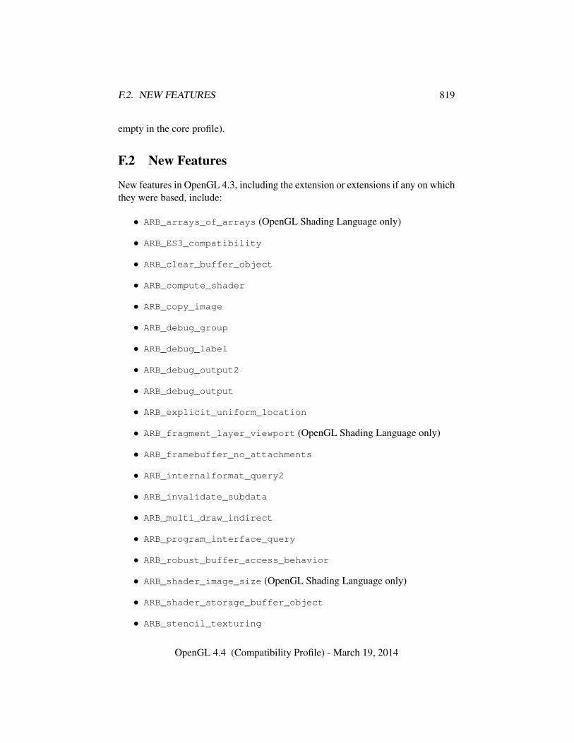
F.2. NEW FEATURES 819
empty in the core profile).
F.2 New Features
New features in OpenGL 4.3, including the extension or extensions if any on whichthey were based, include:
• ARB_arrays_of_arrays (OpenGL Shading Language only)
• ARB_ES3_compatibility
• ARB_clear_buffer_object
• ARB_compute_shader
• ARB_copy_image
• ARB_debug_group
• ARB_debug_label
• ARB_debug_output2
• ARB_debug_output
• ARB_explicit_uniform_location
• ARB_fragment_layer_viewport (OpenGL Shading Language only)
• ARB_framebuffer_no_attachments
• ARB_internalformat_query2
• ARB_invalidate_subdata
• ARB_multi_draw_indirect
• ARB_program_interface_query
• ARB_robust_buffer_access_behavior
• ARB_shader_image_size (OpenGL Shading Language only)
• ARB_shader_storage_buffer_object
• ARB_stencil_texturing
OpenGL 4.4 (Compatibility Profile) - March 19, 2014
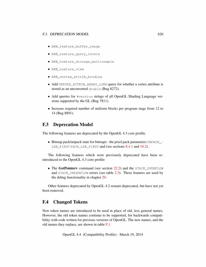
F.3. DEPRECATION MODEL 820
• ARB_texture_buffer_range
• ARB_texture_query_levels
• ARB_texture_storage_multisample
• ARB_texture_view
• ARB_vertex_attrib_binding
• Add VERTEX_ATTRIB_ARRAY_LONG query for whether a vertex attribute isstored as an unconverted double (Bug 8272).
• Add queries for #version strings of all OpenGL Shading Language ver-sions supported by the GL (Bug 7811).
• Increase required number of uniform blocks per program stage from 12 to14 (Bug 8891).
F.3 Deprecation Model
The following features are deprecated by the OpenGL 4.3 core profile.
• Bitmap pack/unpack state for bitmaps - the pixel pack parameters UNPACK_-LSB_FIRST PACK_LSB_FIRST and (see sections 8.4.1 and 18.2).
The following features which were previously deprecated have been re-introduced to the OpenGL 4.3 core profile:
• The GetPointerv command (see section 22.2) and the STACK_OVERFLOW
and STACK_UNDERFLOW errors (see table 2.3). These features are used bythe debug functionality in chapter 20.
Other features deprecated by OpenGL 4.2 remain deprecated, but have not yetbeen removed.
F.4 Changed Tokens
New token names are introduced to be used in place of old, less general names.However, the old token names continue to be supported, for backwards compati-bility with code written for previous versions of OpenGL. The new names, and theold names they replace, are shown in table F.1.
OpenGL 4.4 (Compatibility Profile) - March 19, 2014
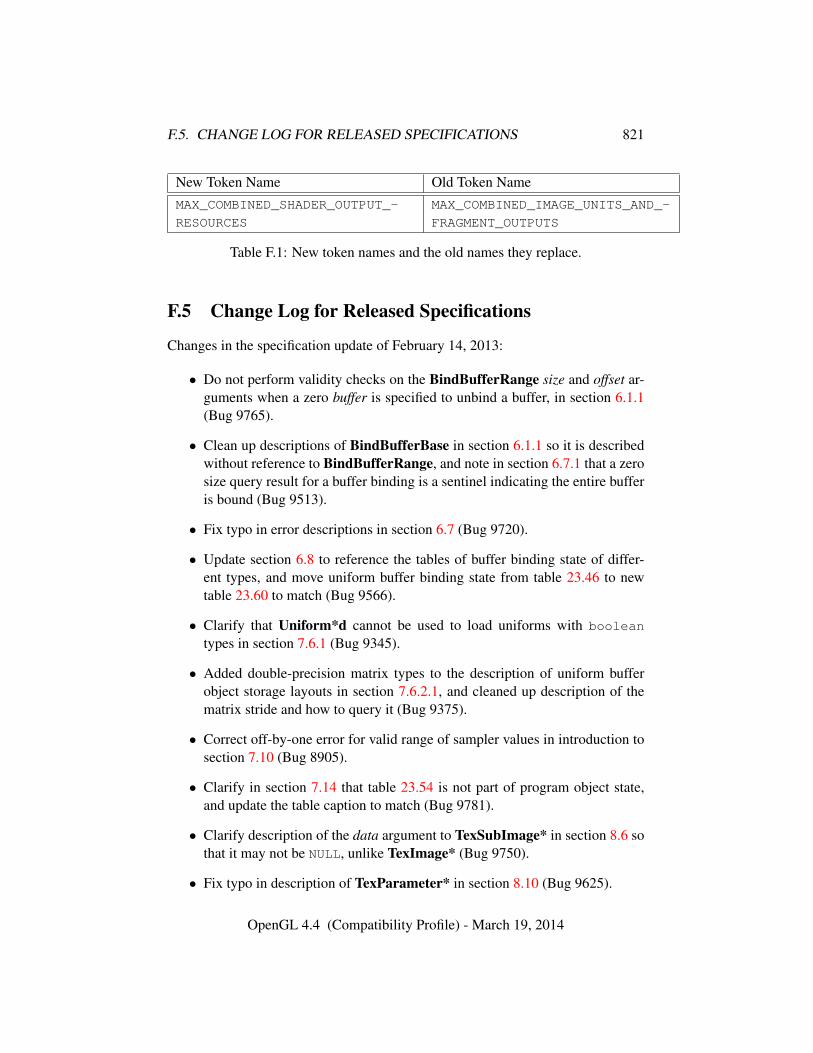
F.5. CHANGE LOG FOR RELEASED SPECIFICATIONS 821
New Token Name Old Token NameMAX_COMBINED_SHADER_OUTPUT_-
RESOURCES
MAX_COMBINED_IMAGE_UNITS_AND_-
FRAGMENT_OUTPUTS
Table F.1: New token names and the old names they replace.
F.5 Change Log for Released Specifications
Changes in the specification update of February 14, 2013:
• Do not perform validity checks on the BindBufferRange size and offset ar-guments when a zero buffer is specified to unbind a buffer, in section 6.1.1(Bug 9765).
• Clean up descriptions of BindBufferBase in section 6.1.1 so it is describedwithout reference to BindBufferRange, and note in section 6.7.1 that a zerosize query result for a buffer binding is a sentinel indicating the entire bufferis bound (Bug 9513).
• Fix typo in error descriptions in section 6.7 (Bug 9720).
• Update section 6.8 to reference the tables of buffer binding state of differ-ent types, and move uniform buffer binding state from table 23.46 to newtable 23.60 to match (Bug 9566).
• Clarify that Uniform*d cannot be used to load uniforms with boolean
types in section 7.6.1 (Bug 9345).
• Added double-precision matrix types to the description of uniform bufferobject storage layouts in section 7.6.2.1, and cleaned up description of thematrix stride and how to query it (Bug 9375).
• Correct off-by-one error for valid range of sampler values in introduction tosection 7.10 (Bug 8905).
• Clarify in section 7.14 that table 23.54 is not part of program object state,and update the table caption to match (Bug 9781).
• Clarify description of the data argument to TexSubImage* in section 8.6 sothat it may not be NULL, unlike TexImage* (Bug 9750).
• Fix typo in description of TexParameter* in section 8.10 (Bug 9625).
OpenGL 4.4 (Compatibility Profile) - March 19, 2014
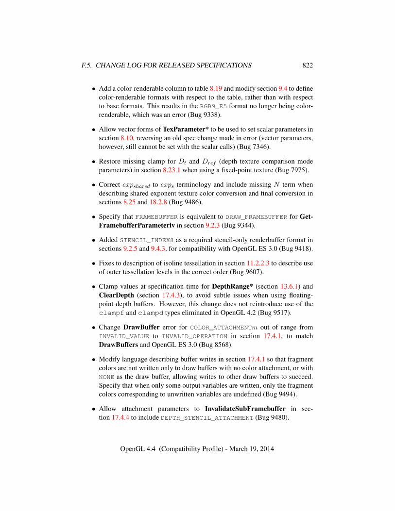
F.5. CHANGE LOG FOR RELEASED SPECIFICATIONS 822
• Add a color-renderable column to table 8.19 and modify section 9.4 to definecolor-renderable formats with respect to the table, rather than with respectto base formats. This results in the RGB9_E5 format no longer being color-renderable, which was an error (Bug 9338).
• Allow vector forms of TexParameter* to be used to set scalar parameters insection 8.10, reversing an old spec change made in error (vector parameters,however, still cannot be set with the scalar calls) (Bug 7346).
• Restore missing clamp for Dt and Dref (depth texture comparison modeparameters) in section 8.23.1 when using a fixed-point texture (Bug 7975).
• Correct expshared to exps terminology and include missing N term whendescribing shared exponent texture color conversion and final conversion insections 8.25 and 18.2.8 (Bug 9486).
• Specify that FRAMEBUFFER is equivalent to DRAW_FRAMEBUFFER for Get-FramebufferParameteriv in section 9.2.3 (Bug 9344).
• Added STENCIL_INDEX8 as a required stencil-only renderbuffer format insections 9.2.5 and 9.4.3, for compatibility with OpenGL ES 3.0 (Bug 9418).
• Fixes to description of isoline tessellation in section 11.2.2.3 to describe useof outer tessellation levels in the correct order (Bug 9607).
• Clamp values at specification time for DepthRange* (section 13.6.1) andClearDepth (section 17.4.3), to avoid subtle issues when using floating-point depth buffers. However, this change does not reintroduce use of theclampf and clampd types eliminated in OpenGL 4.2 (Bug 9517).
• Change DrawBuffer error for COLOR_ATTACHMENTm out of range fromINVALID_VALUE to INVALID_OPERATION in section 17.4.1, to matchDrawBuffers and OpenGL ES 3.0 (Bug 8568).
• Modify language describing buffer writes in section 17.4.1 so that fragmentcolors are not written only to draw buffers with no color attachment, or withNONE as the draw buffer, allowing writes to other draw buffers to succeed.Specify that when only some output variables are written, only the fragmentcolors corresponding to unwritten variables are undefined (Bug 9494).
• Allow attachment parameters to InvalidateSubFramebuffer in sec-tion 17.4.4 to include DEPTH_STENCIL_ATTACHMENT (Bug 9480).
OpenGL 4.4 (Compatibility Profile) - March 19, 2014
F.5. CHANGE LOG FOR RELEASED SPECIFICATIONS 823
• Specify that the BlitFramebuffer mask may be zero in section 18.3.2 (Bug9748).
• Cleaned up language describing parameters to DebugMessageControl insection 20.4 to avoid triple negatives (Bug 9392).
• Increase minimum value for MAX_UNIFORM_BUFFER_BINDINGS to 84 intable 23.75 to account for correct number of bindings/stage (14) (Bug 9424).
Changes in the released Specification of August 6, 2012:
• Restructured as described in section F.1.
• Added new features as described in section F.2.
• Add title image page using the “pipeline metro” diagram.
• Miscellaneous minor typos and fixes to better match OpenGL ES 3.0 speclanguage (Bugs 7885, 7904, 7919).
• Changed “rectangular texture” to “rectangle texture” throughout the spec forconsistency (Bug 9262). Other consistency changes including using “equiv-alent to” consistently for pseudocode samples defining the operation of acommand.
• Many cleanups and additions to error language throughout the spec to addpreviously implicit errors explicitly (however, this is still a work in progress).In particular, added explicit errors for all commands taking program orshader arguments as described at the start of section 7.1, and for commandstaking shadertype arguments (Bug 9145); and added explicit INVALID_-VALUE errors for negative values of sizei and sizeiptr arguments (Bug9320).
• Cleaned up description of function prototypes from the old T notation to T *or const T * as appropriate for the actual C binding of the correspondingcommand.
• Added NUM_SHADING_LANGUAGE_VERSIONS and SHADING_-
LANGUAGE_VERSION queries for supported GLSL #version strings in sec-tions 1.3.1, 1.3.3 and 22.2, and in table 23.68 (see Bug 7811). Still needenum assignments for these.
• Remove assertion that draw and read framebuffers must be of the same classin section 2.1 (Bug 9134).
OpenGL 4.4 (Compatibility Profile) - March 19, 2014
F.5. CHANGE LOG FOR RELEASED SPECIFICATIONS 824
• Clarify in the caption to table 2.2 that sync is defined as a pointer type inthe C binding (Bug 9140).
• Reintroduced STACK_OVERFLOW and STACK_UNDERFLOW errors to the coreprofile in table 2.3, since they are used by the debug group APIs (Bug 9158).
• Describe new, more complete error summary and typesetting style in sec-tion 2.3.1. Convert (most) error summaries beginning with section 4.1,adding implicit error conditions that have not been described with the com-mands they apply to before. This is a work in progress.
• Clean up query objects in section 4.2 to clarify that TIME_ELAPSED andTIMESTAMP queries are different type of queries, and remove an inapplicableerror condition for TIMESTAMP queries (Bug 9268).
• Add language to DeleteBuffers in section 6 and BufferData in section 6.2specifying that these commands cause any existing mappings of a buffer be-ing operated on in any context to be unmapped, per a rather offhand referencein section 6.3.1 (Bug 9323).
• Restore COPY_READ_BUFFER and COPY_WRITE_BUFFER as buffer targetnames in sections 6.1 and 6.6. The _BINDING aliases are used only whenquerying those binding points (Bugs 8475,9115).
• Bring compute shader language in sync with changes to the extension spec.In particular, add DISPATCH_INDIRECT_BUFFER binding section 6.1, de-scribe it in section 10.3.10, update DispatchComputeIndirect to use it insection 19, add new table 23.63, and update aggregate shader limits in sec-tion 23.75 (Bug 9130).
• Add create-on-bind behavior for BindBufferRange and BindBufferBase insection 6.1.1, mirroring BindBuffer (Bug 9216).
• Clarify that offset and alignment constraints for ClearBufferSubData insection 6.2.1 are based on the total size of a texel of type internalformat(size of base type times no. of components) (Bug 9211).
• Update errors for ClearBuffer*Data and mention them and Invalidate-Buffer*Data among the commands that can modify buffer object storagein sections 6.2.1, 7.6, 7.8, and 7.12 (Bug 9154).
• Clarify that buffer mappings are not affected by whether or not a context iscurrent in section 6.3.1 (Bug 9323).
OpenGL 4.4 (Compatibility Profile) - March 19, 2014
F.5. CHANGE LOG FOR RELEASED SPECIFICATIONS 825
• Add language in section 6.3.2 specifying that commands which write to (aswell as read from) mapped buffers are also supposed to generate errors (Bug9115).
• Make InvalidateBuffer*Data generate errors for invalid object handles insection 6.5 (Bug 9341).
• Merge description of different types of indexed array buffer bindings intosection 6.7.1, and move description of target-specific BindBufferRange er-rors into section 6.1.1 with reference to section 6.7.1 (Bug 9115 and generalcleanup).
• Extend ShaderBinary in section 7.2 to allow support for shader binary for-mats including all shader types, not just vertex and fragment shaders (Bug9282).
• Add description of “top-level arrays” to active shader storage block discus-sion in section 7.3.1 (Bug 9115). This probably needs to migrate back to theextension as well, along with a few other language changes in this sectionwhich Pat suggested in his PDF review but hasn’t put into the extension yet.
• Clarify error descriptions for UseProgramStages and ActiveShaderPro-gram (section 7.4), UseProgram (section 7.6.1), and ProgramUniform*(section 7.6.1) to generate an INVALID_OPERATION error “if program hasnot been linked, or was last linked unsucessfully” rather than “if program hasnot been successfully linked” (Bug 8640, tracking similar changes to othercommands previously).
• Merge similar descriptions of uniform variable component limits for eachseparate shader stage into section 7.6.
• Fix nonexistent token ATOMIC_COUNTER_ARRAY_STRIDE to UNIFORM_-
ARRAY_STRIDE in section 7.7.1 (Bug 9346).
• Removed redundant definition of GetSubroutineUniformLocation fromthe beginning of section 7.9.
• Added INVALID_VALUE error in section 7.10 if Uniform1i{v} is used to seta sampler to a value less than zero or greater than or equal to the value ofMAX_COMBINED_TEXTURE_IMAGE_UNITS, matching the similar error forsetting image uniforms.
• Add VERTEX_ATTRIB_ARRAY_LONG state in section 7.13 and table 23.6(Bug 8272).
OpenGL 4.4 (Compatibility Profile) - March 19, 2014
F.5. CHANGE LOG FOR RELEASED SPECIFICATIONS 826
• Add all specific compressed texture formats to the required format list insection 8.5.1. Include EAC and ETC2 format in specific format language intable 8.22 and sections 8.6, 8.7, and 8.24 (Bug 9156).
• Add additional INVALID_OPERATION errors depending on odd combina-tions of read buffer and FBO state for CopyTexImage* and CopyTex-SubImage* in section 8.6 (Bug 8559).
• Disallow CopyTexImage* between sRGB and linear formats in section 8.6,and define BlitFramebuffer to linearize sRGB data from the read buffer insection 18.3.2 (Bug 8560).
• Allow multisample texture targets as arguments to TexParameter* in sec-tion 8.10, with additional error conditions when attempting to set a disal-lowed min filter or base level parameter value.
• Replace listings of all six cube map face selection targets with references totables 8.26 or 9.2, in several places throughout the spec.
• Fix error generated for invalid texture handle passed to TextureView in sec-tion 8.18 (Bug 9337)
• Tweaked descriptions of transferring vertices in sections 10.3.3 and 10.5 tomore closely match OpenGL ES 3.0 (Bug 8686).
• Restore missing description of DrawElementsInstanced in section 10.5.
• Renamed the formal parameter primcount to instancecount for DrawAr-raysInstancedBaseInstance, DrawArraysInstanced, DrawElementsIn-stancedBa-seInstance, DrawElementsInstanced, DrawElementsInstancedBaseVer-tex, and DrawElementsInstancedBaseVertexBaseInstance (section 10.5),and for DrawTransformFeedbackInstanced and DrawTransformFeed-backStreamInstanced (section 13.2.3). Used equivalent terminologyin the pseudocode descriptions of DrawElementsIndirect and DrawAr-raysIndirect (section 10.5). Renamed the formal parameter primcountto drawcount for MultiDrawArrays, MultiDrawArraysIndirect, Mul-tiDrawElements, MultiDrawElementsIndirect, MultiDrawElementsBa-seVertex (section 10.5) (Bug 9230).
• Moved description of GetVertexAttrib* into section 10.6 (Bug 9115).
OpenGL 4.4 (Compatibility Profile) - March 19, 2014
F.5. CHANGE LOG FOR RELEASED SPECIFICATIONS 827
• Specify in section 11.1.1 that special built-in inputs and outputs such as gl_-VertexID should be enumerated in the PROGRAM_INPUT and PROGRAM_-
OUTPUT interfaces, as well as the legacy function GetActiveAttrib. Addspec language counting the built-ins gl_VertexID and gl_InstanceID
against the active attribute limit (Bug 9201).
• Swap order of tessellation levels in describing isoline tessellation in sec-tion 11.2.2.3, to match actual hardware (Bug 9195).
• Remove language about deferred deletion for DeleteTransformFeedbacksin section 13.2.1 (Bug 8948).
• Add transform feedback-related error for ProgramBinary (matching exist-ing error for LinkProgram in section 13.2.2 when program is the name of aprogram being used by one or more transform feedback objects (Bug 7928).
• Add description of MAX_COMPUTE_SHARED_MEMORY_SIZE in section 19.1,lifted from GLSL spec (Bug 9069).
• Add description of the type of the debug callback function, includingplatform-dependent calling conventions, in section 20.2. 21.1
• Cleaned up section 21.1 to use a naming scheme for parameters that matchesthe names of evaluator command parameters in gl.h.
• Remove inaccurate description of GLSL version string sort order in sec-tion 22.2. Instead, ensure that the most recent GLSL version correspondingto the context profile is returned first, and other entries have no defined or-dering (Bug 7811).
• Change Zn terminology used in state tables to describe enumerated statewith n possible values to E throughout, since maintaining the n was alwaystricky as features were added and the possible values are fully described inthe spec body. This affects hundreds of state table entries as well as addinga description of E in table 23.1.
• Move IMPLEMENTATION_COLOR_READ_FORMAT andIMPLEMENTATION_COLOR_READ_TYPE from table 23.85 to table 23.64since they are not framebuffer-dependent values, unlike OpenGL ES (Bug8561).
• Increased minimum values for MAX_VERTEX_UNIFORM_BLOCKS, MAX_-TESS_CONTROL_UNIFORM_BLOCKS, MAX_TESS_EVALUATION_-
OpenGL 4.4 (Compatibility Profile) - March 19, 2014
F.6. CREDITS 828
UNIFORM_BLOCKS, MAX_GEOMETRY_UNIFORM_BLOCKS, MAX_-
FRAGMENT_UNIFORM_BLOCKS, and MAX_COMPUTE_UNIFORM_BLOCKS to14 in tables 23.69, 23.70, 23.71, 23.72, 23.73, and 23.74 respectively, andof MAX_COMBINED_UNIFORM_BLOCKS to 70 in table 23.75 (Bug 8891).
• Added UNPACK_LSB_FIRST and PACK_LSB_FIRST state to the deprecatedfeatures list in section F.3 (Bug 7865).
F.6 Credits
OpenGL 4.3 is the result of the contributions of many people and companies. Mem-bers of the Khronos OpenGL ARB Working Group during the development ofOpenGL 4.3, including the company that they represented at the time of their con-tributions, follow.
Some major contributions made by individuals are listed together with theirname, including specific functionality developed in the form of new ARB exten-sions together with OpenGL 4.3. In addition, many people participated in develop-ing earlier vendor and EXT extensions on which the OpenGL 4.3 functionality isbased in part; those individuals are listed in the respective extension specificationsin the OpenGL Registry.
Aaron Plattner, NVIDIAAcorn Pooley, NVIDIAAhmet Oguz Akyuz, AMDAlex Eddy, Apple IncAnton Staaf, GoogleBarthold Lichtenbelt, NVIDIA (Chair, Khronos OpenGL ARB Working Group)Benj Lipchak, AppleBenjamin Morris, NVIDIABill Licea-Kane (Chair, ARB OpenGL Shading Language TSG)Brent Wilson, NVIDIABruce Merry, IndependentChris Marrin, AppleChris Niederauer, Apple IncChristophe Riccio (ARB_debug_group, ARB_debug_label, ARB_shader_-
image_size, ARB_texture_query_levels, KHR_debug_output)Christophe Riccio, AMDDan Omachi, Apple IncDaniel Koch, TransGaming Inc. (ARB_internalformat_query2)Daniel Rakos, AMD
OpenGL 4.4 (Compatibility Profile) - March 19, 2014
F.6. CREDITS 829
Eric Werness, NVIDIAGeorg Kolling, Imagination TechnologiesGraham Sellers, AMD (ARB_multi_draw_indirect, ARB_clear_-
buffer_object, ARB_compute_shader, ARB_copy_image, ARB_-
texture_buffer_range, ARB_texture_storage_multisample)Greg Roth, NVIDIAHenri Verbeet, CodeWeaversJaakko Konttinen, AMD (ARB_debug_output)James Jones, NVIDIAJan-Harald Fredriksen, ARMJason Green, TransGamingJean-Franois Roy, AppleJeff Bolz, NVIDIA (ARB_invalidate_subdata, ARB_texture_view,
ARB_vertex_attrib_binding)Joe Kain, NVIDIAJohn Kessenich, Independent (OpenGL Shading Language Specification Editor,
ARB_arrays_of_arrays)Bill Licea-Kane (Chair, ARB OpenGL Shading Language TSG)Jon Leech, Independent (OpenGL API Specification Editor)Kenneth Russell, Google (ARB_robustness_isolation)Kent Miller, AppleLingjun (Frank) Chen, QualcommMark Callow, HI CorporationMark Kilgard, NVIDIA (ARB_robustness)Mark Young, AMDMathias Schott, NVIDIAMatt Collins, AppleMaurice Ribble, QualcommMichael Gold, NVIDIA (ARB_copy_image)Michael Morrison, NVIDIAPat Brown, NVIDIA (ARB_framebuffer_no_attachments, ARB_-
program_interface_query, ARB_shader_storage_buffer_-
object)Pierre Boudier, AMDPiers Daniell, NVIDIA (ARB_ES3_compatibility, ARB_debug_-
output2, ARB_explicit_uniform_location, ARB_fragment_-
layer_viewport, ARB_robust_buffer_access_behavior, ARB_-
stencil_texturing)Richard Schreyer, AppleSeth Sowerby, Apple
OpenGL 4.4 (Compatibility Profile) - March 19, 2014

F.7. ACKNOWLEDGEMENTS 830
Thomas Volk, NVIDIATim Johansson, OperaVladimir Vukicevic, MozillaYaki Tebeka, Graphic RemedyYuan Wang, IMG
F.7 Acknowledgements
The ARB gratefully acknowledges administrative support by the members of GoldStandard Group, including Andrew Riegel, Elizabeth Riegel, Glenn Fredericks,and Michelle Clark, and technical support from James Riordon, webmaster ofKhronos.org and OpenGL.org.
The “pipeline metro” cover image was created by Dominic Agoro-Ombaka ofGold Standard Group.
OpenGL 4.4 (Compatibility Profile) - March 19, 2014
Appendix G
Version 4.4
OpenGL version 4.4, released on July 22, 2013, is the sixteenth revision since theoriginal version 1.0.
Separate versions of the OpenGL 4.4 Specification exist for the core profileand compatibility profile described in appendix D, respectively subtitled the “CoreProfile” and the “Compatibility Profile”. This document describes the Compati-bility Profile. An OpenGL 4.4 implementation must be able to create a contextsupporting the core profile, and may also be able to create a context supporting thecompatibility profile.
Material specific to the compatibility profile specification is marked in a dis-tinct color to clearly call out differences between the two profiles.
The OpenGL 4.4 compatibility and core profiles are upward compatible withthe OpenGL 4.3 compatibility and core profiles, respectively (see appendix F).
Following are brief descriptions of changes and additions to OpenGL 4.4. De-scriptions of changes and additions in versions of OpenGL prior to 4.2 are omittedin this Specification, but may be found in the OpenGL 3.0 Specification (for fea-tures in versions 1.0 - 3.0, inclusive) and the OpenGL 4.2 Specification (for featuresin versions 3.1 - 4.1, inclusive). These Specifications are available in the OpenGLRegistry.
G.1 New Features
New features in OpenGL 4.4, including the extension or extensions if any on whichthey were based, include:
• ARB_buffer_storage
• ARB_clear_texture
831
G.2. DEPRECATION MODEL 832
• ARB_enhanced_layouts
• ARB_multi_bind
• ARB_query_buffer_object
• ARB_texture_mirror_clamp_to_edge
• ARB_texture_stencil8
• ARB_vertex_type_10f_11f_11f_rev
• New implementation-dependent state MAX_VERTEX_ATTRIB_STRIDE,which constrains the maximum value of stride parameters to vertex arraypointer-setting commands.
G.2 Deprecation Model
No new features are deprecated, and no previously deprecated features are re-introduced by the OpenGL 4.4 core profile.
Features deprecated by OpenGL 4.3 remain deprecated, but have not yet beenremoved.
G.3 Change Log for Released Specifications
Changes in the released Specification update of March 19, 2014:
• Fix typos and apply minor non-semantic language changes in several placesto more closely match the OpenGL ES 3.1 Specification.
• Tweak Enable / Disable language for different targets throughout the specfor more consistency.
• Modify language in section 5.1.2 so that binding-related state is restored todefault values after automatic unbinds (Bugs 10076, 11630).
• Add samplers to the list of object types in section 5.1.3 for which deletion isdelayed until the object is no longer in use, and remove transform feedbackobjects since deletion is defined to generate an error while they are active(Bugs 11374, 10079).
• Add atomic counter binding, offset and stride assignments to the values resetby ProgramBinary in section 7.5 (bugfix from ES spec).
OpenGL 4.4 (Compatibility Profile) - March 19, 2014
G.3. CHANGE LOG FOR RELEASED SPECIFICATIONS 833
• Move Uniform* errors to section 7.6.1 where the Uniform* commands aredefined, from sections 7.10 and 7.11
• Correct typo MAX_ATOMIC_COUNTER_BUFFERS to MAX_COMBINED_-
ATOMIC_COUNTER_BUFFERS in section 7.7, and specify new program in-terface query for atomic counter buffer data size query in section 7.7.2
• Restrict error for UniformSubroutinesuiv in section 7.9 to the case whereno program stage is active for the shader stage identified by shadertype (Bug11306).
• Update DeleteSamplers language in section 8.2 to allow for the case wherea sampler is bound to multiple texture units (bugfix from ES spec).
• Fix conversion equation reference for SamplerParameteriv in section 8.2.Reorganize descriptions of exceptions to default data conversion rules hereand in section 8.10 for TexParameter* (Bug 11185).
• Add error in section 8.2 for calling scalar SamplerParameter{if} en-try points with non-scalar param tokens, matching TexParameter* (Bug11186).
• Add error for TexImage3D in section 8.5 when specifying invalid borderor target values with specific compressed texture formats, matching Com-pressedTexImage3D (Bug 11239).
• Update table 8.19 in section 8.5.2 to make all remaining sized color formatstexture-renderable that were not already, since the component size promotionrules mean there are already required texture formats with the same formatand as least as many bits/component (Bug 11097).
We discussed but did not also make these formats required renderbuffer for-mats, because doing this might imply a format change when a format sup-ported at exactly the required component size for textures is only supportedat a larger component size for renderbuffers (e.g. create texture at RGB4,use as a texture, then use as a renderbuffer and find it has to be converted toRGB565).
• Change maximum allowed texture size for TexImage3DMultisample insection 8.8 to the value of MAX_ARRAY_TEXTURE_LAYERS (Bug 11135).
• Remove explicit OUT_OF_MEMORY errors from TexImage*Multisample insection 8.8 and RenderbufferStorageMultisample in section 9.2.4. (publicBug 952).
OpenGL 4.4 (Compatibility Profile) - March 19, 2014
G.3. CHANGE LOG FOR RELEASED SPECIFICATIONS 834
• Add subsection headings and Errors sections for GetTexParameter* andGetTexLevelParameter* in section 8.11.
• Change formal parameter names value and data to pname and params,following the headers and man pages, for GetTexParameter* and Get-TexLevelParameter* (see section 8.11). Also make this change for Get-TexGen* (see section 12.1.3.1), GetLight* and GetMaterial* (see sec-tion 12.2.4), and GetTexEnv* (see section 16.1.1). (Bug 11523).
• Added per-target maximum level-of-detail values to definition of Get-TexLevelParameter* in section 8.11.3 (Bug 11136)
• Add error for GetTexLevelParameter* in section 8.11 when queryingmultisample-specific parameters for non-multisample textures (this was im-ported from the OpenGL ES spec and it’s not certain it should be here).
• Define behavior of GetTexLevelParameter* in section 8.11.3 for queries ofmultisample state from non-multisampled textures (Bug 11814).
• Change rounding mode for layer numbers of array textures in section 8.14.2to prefer round-to-nearest-even, while still allowing old spec behavior (Bug11399).
• Add cube map array texel arrays to the enumerated state in section 8.22, andremove redundant description of the bound buffer texture object name.
• Add description of DEPTH_STENCIL_TEXTURE_MODE in section 8.22, andcorrect its type in table 23.20 (Bug 11770).
• Add section 8.26.1 summarizing image unit binding state (Bug 10076).
• Restructure error condition for FramebufferParameteri in section 9.2.1 toavoid ambiguity (Bug 11831).
• Define GetFramebufferAttachmentParameteriv in section 9.2.3 to returnNONE when querying the object type of depth or stencil attachments, thedefault framebuffer is bound, and the corresponding buffer of the defaultframebuffer has zero bits (Bug 10908).
• Clean up language describing the GetFramebufferAttachmentParam-eteriv query for FRAMEBUFFER_ATTACHMENT_TEXTURE_LAYER in sec-tion 9.2.3 (Bug 11102).
OpenGL 4.4 (Compatibility Profile) - March 19, 2014
G.3. CHANGE LOG FOR RELEASED SPECIFICATIONS 835
• Remove bogus error condition for FramebufferRenderbuffer, and add er-rors for invalid layer depending on texture type in section 9.2.7 (bugfix fromES spec).
• Set the vertex attribute array pointer state explicitly in the pseu-docode for VertexAttrib*Pointer in section 10.3.1, and define queriesof VERTEX_ATTRIB_ARRAY_BUFFER_BINDING and VERTEX_ATTRIB_-
ARRAY_DIVISOR to look up the corresponding state via the vertex attributebinding in section 10.6 (Bug 11789).
• Rewrite section 10.3.10 to merge language for indirect drawing and indirectcompute dispatch commands (Bug 11601).
• Fix texel fetch limit on layer for array textures in section 11.1.3.2 (Bug11770).
• Fix typo in section 11.1.3.7 (Bug 11553).
• Relax restrictions on required shader stages in sections 11.2 and 11.3 so thatseparable program objects containing tessellation and geometry shaders arenot also required to contain a vertex shader (Bug 11508).
• Modify tessellation primitive generation language in section 11.2.2 to dis-card patches only when relevant outer tessellation levels are NaNs, but notfor non-relevant levels (Bug 11484).
• Add missing error for invalid pname to GetMultisamplefv in section 14.3.1(Bug 11134).
• Change error for invalid mode* parameters to BlendEquation* in sec-tion 17.3.8.1 to INVALID_ENUM (bug 11354).
• Fix error for invalid blending function arguments in section 17.3.8.2 toINVALID_ENUM (Bug 11770).
• Add errors for ClearBuffer* in section 17.4.3.1 when the wrong type ofbuffer is passed to different forms of the command (Bug 11139).
• Fix table reference in description of ClearBuffer* in section 17.4.3.1from 17.5 to 17.4 so it’s clear that DRAW_BUFFERi can contain any legalvalue and the corresponding buffers will be cleared (Bug 11463).
• Modify caption for table 17.4 in section 17.4.1 so it’s clear table entries referonly to selected buffers for the draw buffer, and remove redundant descrip-tion of initial draw buffers state (Bugs 11462, 11463).
OpenGL 4.4 (Compatibility Profile) - March 19, 2014

G.3. CHANGE LOG FOR RELEASED SPECIFICATIONS 836
• Moved language allowing undefined behavior for overlapping copies to thebeginning of section 18.3, extended it to the case of overlapping copies viatexture views, applied it to all pixel copy operations in the section, and re-stricted the effects to undefined pixel values rather than general undefinedbehavior (Bug 11355).
• Replace the “Get Value” of LABEL with - for debug labels of objects intables 23.6, 23.9, 23.20, 23.23, 23.30, 23.33, 23.41, 23.42, 23.43, 23.55,23.59, 23.61, and 23.87 (Bug 11131).
• Clarified description of sourcing generic vertex attributes from client mem-ory in section 10.3.8. Rewrote descriptions of the vertex binding-specific state in table 23.7, added missing VERTEX_BINDING_DIVISOR andVERTEX_BINDING_BUFFER state, and marked all such state as part of thevertex-array attribute group (in the compatibility profile only) (Bug 10736).
• Add missing state for framebuffers with no attachment to tables 23.30and 23.81 (Bug 11187).
• Add missing COMPUTE_SHADER state to program pipeline objects in ta-ble 23.42 (Bug 11539).
Changes in the released Specification update of October 18, 2013:
• Add footnote to section 2.3.1 noting that OUT_OF_MEMORY errors are notexplicitly shown in command-specific Error sections because all GL com-mands can potentially generate them. Remove explicit OUT_OF_MEMORY er-rors from BufferStorage, BufferData, and MapBufferRange in section 6,and the TexStorage* commands in section 8.19 (public Bug 952).
• Add new section 2.4 defining the term rendering commands, and modifylanguage using this term in sections 7.10, 9.4.4, 10.3.8, 10.10, and 11.1.3.12to use the new definition, sometimes narrowed to drawing commands, or torendering commands which invoke shaders (Bug 10403).
• Add footnote to section 2.6.9 specifying that undefined behavior resultswhen mixing non-shared core API framebuffer objects and shared EXT ex-tension framebuffer objects (Bug 10738).
• Change description of BufferStorage MAP_COHERENT_BIT in section 6.2to say that changes are “visible to any subsequently issued GL commands”rather than “immediately visible” (Public Bug 935).
OpenGL 4.4 (Compatibility Profile) - March 19, 2014
G.3. CHANGE LOG FOR RELEASED SPECIFICATIONS 837
• Remove error for BufferStorage in section 6.2 which did not allow flags tocontain MAP_WRITE_BIT while not also containing DYNAMIC_STORAGE_-
BIT (Bug 10561, public Bug 925).
• Rewrite section 6.3.2 describing the effects of mapped buffers on other com-mands and possible resulting errors or undefined behavior (Bug 10684).
• Update GetProgramResourceiv in section 7.3.1 to return one for ARRAY_-SIZE queries of non-arrays (for compatibility with GetActiveUniform) andzero for explicitly unsized arrays, and describe circumstances in whichqueries of ARRAY_SIZE and TOP_LEVEL_ARRAY_SIZE for unknown arraysizes may return zero (Bugs 10641, 10647).
• Allow ActiveShaderProgram and UseProgramStages to accept zero pro-gram values in section 7.4, to reset the corresponding program pipeline ob-ject state to its initial value (Public Bug 871).
• Add additional const qualifier to parameter type of uniformNames forGetUniformIndices in section 7.6 (Bug 10703).
• Fix typo from SHADER_STORAGE_BLOCK to SHADER_STORAGE_BUFFER
for ShaderStorageBlockBinding in section 7.8 (Bug 10795).
• Fix list of supported texture targets for stencil, depth, and depth+stencil for-mats in section 8.5 to include multisample targets (Bug 10558).
• Move descriptions of required texture and renderbuffer/texture formats intotables 8.19 and 8.21, and update language in sections 8.5.1, 9.2.5, 9.4,and 9.4.3 to refer to those tables and to describe required framebuffer for-mats as color-renderable. Also, merged the no-longer-existent table 9.1 ofrenderbuffer-only stencil formats into table 8.21, and modified the definitionof stencil-renderable in section 9.4 accordingly (Bug 9338).
• Tag type of stencil fields in table 8.21 as ui (Bug 10748).
• Add error for TexImage*DMultisample in section 8.8 when internalformatis not a valid format (Bug 11018).
• Change type of internalformat argument to TexImage2DMultisample andTexImage3DMultisample in section 8.8 to enum, since the legacy internalformats are never accepted by these commands (Bug 10496).
• Note that during computation of scale factors in section 8.14.1, implementa-tions have chosen to perform clamping of intermediate terms in the sum oflevel-of-detail biases differently (Bug 9779).
OpenGL 4.4 (Compatibility Profile) - March 19, 2014
G.3. CHANGE LOG FOR RELEASED SPECIFICATIONS 838
• Specify how border color values are clamped for compressed texture imageformats in table 8.22 and section 8.14.2 (Bug 9476).
• Specify behavior of GetFramebufferAttachmentParameteriv in sec-tion 9.2.3 when querying texture attachments which have not yet specified atexture image or which do not yet have an allocated image store, and fix theerror generated when querying a combined depth+stencil attachment to ap-ply to the component type query, rather than the color encoding query (Bugs9170,10357).
• Clean up errors for FramebufferTexture*D in section 9.2.8 (Bug 10674).
• Merge rows of table 10.2 for VertexAttrib*Format and VertexAt-trib*Pointer commands which are otherwise identical (Bug 10692).
• Rewrite description of BindVertexBuffer in section 10.3.1 to clarify that itmay create buffers in the same fashion as BindBuffer (Bug 10693).
• Explicitly specify in section 10.3.1 that the VertexAttrib*Pointer com-mands may generate any of the errors defined by VertexAttrib*Format andVertexAttribBinding, since the pseudocode invokes those commands (Bug10631). This was implicit in the previous spec language and has simply beencalled out more explicitly for clarity without replicating the errors.
• Typo fix in error summary for ClientActiveTexture in section 10.3.2 (Bug10673).
• Add PRIMITIVE_RESTART_FOR_PATCHES_SUPPORTED to section 10.3.5and table 23.64 to allow querying primitive restart support for patch primi-tives (Bug 10364). Note that some implementations already could not sup-port this, but had no way to indicate this.
• Drop bogus references to “disabled attributes” in section 10.3.6 (Bug 10695).
• Generate INVALID_VALUE errors consistently for misaligned indirect pa-rameters to DrawArraysIndirect and DrawElementsIndirect in sec-tion 10.5, and DispatchComputeIndirect in section 19 (Bug 10385).
• Use GL types instead of type name tokens in caption for table 10.8 (Bug10636).
• Clarify in sections 11.1.3.5 and 15.2.1 that swizzling during texture lookupsof textures with depth component data is always performed, whether depthcomparision is disabled or enabled (Bug 10702, Public Bug 749).
OpenGL 4.4 (Compatibility Profile) - March 19, 2014
G.3. CHANGE LOG FOR RELEASED SPECIFICATIONS 839
• Restrict description in section 11.1.3.12 of checks required to be performedby ValidateProgram to only the errors described in that section (Bug10650).
• Remove a sentence fragment accidentally left in the description of Vali-dateProgramPipeline in section 11.1.3.12.
• Specify in section 14.3.1 that the value of SAMPLE_BUFFERS is framebuffer-dependent, like SAMPLES (Bug 10688).
• Remove redundant language describing depth texture lookups in sec-tion 15.2.1 and replace with a link to section 11.1.3.5, which also has someadditional bugfixes that were not present here (Bug 10997).
• Move a paragraph in section 15.2.2 to near the end of the section for betterflow (Bug 10687).
• Restrict language disallowing writing to multiple “classes” of fragmentshader outputs in section 15.2.3 to compatibility profile only (Bug 10126).
• Restore TEXTURE_RECTANGLE target to section 16.2 and table 23.17 (Bug10671).
• Improve language describing undefined behavior when different color valuesare written to the same multiply-attached color buffer, and move it fromsection 17.3.11 to section 17.4.1 (Bug 10983).
• Specify in section 18.3.2 that linearization of sRGB formats duringreads performed by blending and blitting operations is controlled by theFRAMEBUFFER_SRGB enable (Bug 8560).
• Change the type of FRAMEBUFFER_ATTACHMENT_LAYERED in table 23.31from n×B to B.
• Restore missing TEXTURE_BUFFER_BINDING query in table 23.87 for thebuffer object bound to the corresponding bind point (Bug 4353, public Bug844).
Changes in the released Specification of July 22, 2013:
• Added new features as described in section G.1.
• Changed references throughout the spec to the value of SAMPLE_BUFFERSbeing “greater than zero” to “one”, since it can only take on values of zeroand one.
OpenGL 4.4 (Compatibility Profile) - March 19, 2014
G.3. CHANGE LOG FOR RELEASED SPECIFICATIONS 840
• Added introductory subsection 1.4 describing how to file bug reports againstthe GL and GLSL Specifications in the Khronos public Bugzilla (public bug379).
• Added a note that querying QUERY_RESULT_AVAILABLE for a query objectwill eventually succed in section 4.2.1 (Bug 9766).
• Add views of an object’s data store to the list of conditions in sections 5and 5.1.3 under which an object is considered in use for purposes of deter-mining object lifetimes (Bug 10511).
• Minor clarifications in sections 5.3.1, 8.21, 7.6.3, 7.7.2, 7.8, 13.1, and 15.2.1(Bug 10346).
• Added INVALID_VALUE error for BindBufferRange in section 6.1.1 if off-set is negative (Bug 9873).
• Add BufferSubData error for immutable storage without dynamic draw flagin section 6.2 (Bug 10326).
• Modified prototypes for vector forms of the commands GetCon-volutionParameter (section 8.4.3.8), GetHistogramParameter (sec-tion 8.4.3.13), GetMinmaxParameter (section 8.4.3.16), MultiTexCo-ord*v (section 10.2.2), GetTexParameter* and GetTexLevelParameter*(section 8.11.1), and VertexAttrib4Nub (section 10.2.1), so that they arepassed pointers rather than scalars as suggested by the ’T’ notation (publicbug 273).
• Clarify that no specific compressed one-dimensional texture formats are sup-ported by the API, but may be by extensions, in section 8.7 (Bug 10388).
• Restore errors for setting invalid rectangle texture parameters in section 8.10(Bug 10208).
• Move language constraining levelbase and levelmax for immutable texturesfrom section 8.10 to section 8.14.3 (Bug 9342).
• Added alternate mipmap level selection computation in equation 8.11 (Bug10119).
• Add forward references to pixel packing and PACK_* pixel storage modesfrom descriptions of texture queries and PixelStore in sections 8.11, 8.4.1,and 18.4 (Bug 10380).
OpenGL 4.4 (Compatibility Profile) - March 19, 2014
G.3. CHANGE LOG FOR RELEASED SPECIFICATIONS 841
• Describe wrap mode application for MIRROR_CLAMP_TO_EDGE consistentlywith other modes in table 8.27, and use mod math operator instead offmod() function since the inputs are described in non-scaled integer co-ordinates (Bug 10432).
• Use actual VIEW_CLASS_* compatibility class names in table 8.29 insteadof abstract class names, and refer to these tokens from the description ofVIEW_COMPATIBILITY_CLASS in section 22.3.2 instead of enumeratingthem again (Bug 10518).
• Change completeness condition for stencil index textures and stencil tex-turing from depth+stencil textures to match other integer textures in sec-tion 8.17 (Bug 10372).
• Add number of samples to proxy texture state in section 8.22 and specifythat its value is not checked for multisample textures (Bug 10171).
• Add error for querying component type of a combined depth+stencil bufferwith GetFramebufferAttachmentParameteriv in section 9.2.3, and notethat the color encoding for non-color buffers is returned as LINEAR (Bug9170).
• Add conditions in section 9.4.1 for texture image attachments, makingframebuffer attachment completeness dependent on valid mipmap level andmipmap completness of the image and including the case where texture im-age attachment is part of a cubemap texture, which must be mipmap cubecomplete (Bug 9689).
• Remove redundant paragraph from section 10.2 (Bug 10311).
• Limit stride parameters to BindVertexBuffer* and the generic and fixed-function vertex array specification commands in section 10.3 to the value ofthe new implementation-dependent state MAX_VERTEX_ATTRIB_STRIDE intable 23.67 (Bug 10229).
• Move non-local error descriptions for *Indirect* rendering and dispatchcommands to live with the commands themselves in sections 10.3.10, 10.5,and 19 (Bug 10385).
• Only allow generated buffer object names in the core profile for BindVer-texBuffer in section 10.3.1 (Bug 10486).
• Added BlitFramebuffer to commands affected by conditional rendering insection 10.10 (Bug 9562).
OpenGL 4.4 (Compatibility Profile) - March 19, 2014
G.3. CHANGE LOG FOR RELEASED SPECIFICATIONS 842
• Restore error for BindAttribLocation attribute variable names starting withthe reserved "gl_" prefix to core profile in section 11.1.1 (Bug 10203).
• Clarify that GetTransformFeedbackVarying may be used to query anytransform feedback varying variable in section 11.1.2.1 (Bug 10472).
• Add a non-local error in section 13.2.2 for GL commands that attempt to reador write to an active and unpaused transform feedback buffer (Bug 10193).
• Changed type of GetPolygonStipple argument to ubyte in section 14.6.2to match shipping header files and be typesafe (Bug 10110).
• Clean up description of GetFragData* in section 15.2.3 (bug 10127).
• Made default value for ALPHA_TEST_REF floating-point in section 17.3.4,and changed query in table 23.26 to GetFloatv (Bug 10128).
• Strike redundant language describing default/FBO bindings under Draw-Buffer (see section 17.4.1) and ReadBuffer (section 18.2.1). Bring lan-guage for the two sections in sync, and restore errors for ReadBuffer corre-sponding to DrawBuffer (Bug 10172).
• Fix error specified for ColorMaski in section 17.4.2 to specify the correctformal parameter name, buf, and be restricted to that command (public bug256).
• Minimize use of generic ClearBuffer* terminology, since Clear-Buffer*Data behave differently than the similarly named commands in sec-tion 17.4.3 with respect to conditional rendering and rasterizer discard (Bug10312).
• Clarify that ClearBuffer* can clear any valid draw buffers in sec-tion 17.4.3.1, and that the commands have no effect when the selected drawbuffer has the value NONE (Bug 10537).
• Relax BlitFramebuffer in section 18.3.2 so that format conversion can takeplace during multisample blits, since drivers already allow this and someapps depend on it. Simplified references to SAMPLE_BUFFERS by using theterm “multisampled”. Cleaned up the Errors section and moved errors fromspec body language into it (Bugs 9692, 10219).
• Add const attribute to userParam argument of DebugMessageCallbackand DEBUGPROC in section 20.2. Specify that unrecognized message IDsin DebugMessageControl ids array are ignored in section 20.4. Specify
OpenGL 4.4 (Compatibility Profile) - March 19, 2014
G.4. CREDITS 843
in section 20.9 that GetDebugMessageLog messageLog parameter must beNULL when bufSize is less than zero, to allow an early out. (Bug 10083).
• Reorganize section 22.3 to group internal format query pnames by the typeof query and sort them, and add CLEAR_TEXTURE pname to match extensionspec.
• Add missing PRIMITIVE_RESTART_FIXED_INDEX to table 23.8 (Bug10250).
• Clean up state table entries to indicate enumerated types in tables 23.8,23.11, 23.19, 23.23, 23.24, 23.31, and 23.33 (Bug 10251).
• Fixed types of CLIP_DISTANCEi and DEPTH_RANGE table 23.10 (Bugs10106, 10107).
• Add missing UNIFORM_BLOCK_NAME_LENGTH state to table 23.47 (Bug8136).
• Correct section references from table 23.65 for MAX_ATTRIB_STACK_-
DEPTH and MAX_CLIENT_ATTRIB_STACK_DEPTH (Bug 10572).
• Change minimum number of compressed texture formats to 18 in ta-ble 23.67, comprising the required specific formats in table 8.22 (Bug 7235).
G.4 Credits
OpenGL 4.4 is the result of the contributions of many people and companies. Mem-bers of the Khronos OpenGL ARB Working Group during the development ofOpenGL 4.4, including the company that they represented at the time of their con-tributions, follow.
Some major contributions made by individuals are listed together with theirname, including specific functionality developed in the form of new ARB exten-sions together with OpenGL 4.4. In addition, many people participated in develop-ing earlier vendor and EXT extensions on which the OpenGL 4.4 functionality isbased in part; those individuals are listed in the respective extension specificationsin the OpenGL Registry.
Alon Or-bach, SamsungAras Pranckevicius,Barthold Lichtenbelt, NVIDIA (Chair, Khronos OpenGL ARB Working Group)Benj Lipchak, Apple
OpenGL 4.4 (Compatibility Profile) - March 19, 2014
G.5. ACKNOWLEDGEMENTS 844
Benji Bowman, Imagination TechnologiesBill Licea-Kane, AMDBrent Insko, IntelBruce Merry, IndependentChristoph Kubisch, NVIDIAChristophe Riccio, AMDDaniel Koch, NVIDIA (GL_ARB_clear_texture, GL_ARB_texture_-
mirror_clamp_to_edge, GL_ARB_vertex_type_10f_11f_11f_rev)Daniel Rakos, AMD (GL_ARB_query_buffer_object)Graham Connor, Imagination TechnologiesGraham Sellers, AMD (GL_ARB_buffer_storage)Ian Romanick, IntelJames Helferty, NVIDIAJames Jones, NVIDIAJeff Bolz, NVIDIA (GL_ARB_texture_stencil8)John Kessenich, Independent (OpenGL Shading Language Specification Editor,
GL_ARB_enhanced_layouts)Jon Leech, Independent (OpenGL API Specification Editor)Jonathan Putsman, Imagination TechnologiesKarol Gasinski, IntelLarry Seiler, IntelLingjun (Frank) Chen, QualcommMark Callow, ArtsparkNick Penwarden, Epic GamesPat Brown, NVIDIA (GL_ARB_multi_bind)Pierre Boudier, AMDPiers Daniell, NVIDIARob Barris, NVIDIARobert Simpson, QualcommSlawomir Grajewski, IntelTim Foley, IntelTom Olson, ARM
G.5 Acknowledgements
The ARB gratefully acknowledges administrative support by the members of GoldStandard Group, including Andrew Riegel, Elizabeth Riegel, Glenn Fredericks,and Michelle Clark, and technical support from James Riordon, webmaster ofKhronos.org and OpenGL.org.
OpenGL 4.4 (Compatibility Profile) - March 19, 2014

G.5. ACKNOWLEDGEMENTS 845
The “pipeline metro” cover image was created by Dominic Agoro-Ombaka ofGold Standard Group.
OpenGL 4.4 (Compatibility Profile) - March 19, 2014
Appendix H
OpenGL Registry, Header Files,and ARB Extensions
H.1 OpenGL Registry
Many extensions to the OpenGL API have been defined by vendors, groups ofvendors, and the OpenGL ARB. In order not to compromise the readability ofthe OpenGL Specification, such extensions are not integrated into the core lan-guage; instead, they are made available online in the OpenGL Registry, togetherwith extensions to window system binding APIs, such as GLX and WGL, and withspecifications for OpenGL, GLX, and related APIs.
Extensions are documented as changes to a particular version of the Specifica-tion. The Registry is available on the World Wide Web at URL
http://www.opengl.org/registry/
H.2 Header Files
Historically, C and C++ source code calling OpenGL was to #include a singleheader file, <GL/gl.h>. In addition to the core OpenGL API, the APIs for allextensions provided by an implementation were defined in this header.
When platforms became common where the OpenGL SDK (library and headerfiles) were not necessarily obtained from the same source as the OpenGL driver,such as Microsoft Windows and Linux, <GL/gl.h> could not always be keptin sync with new core API versions and extensions supported by drivers. At thistime the OpenGL ARB defined a new header, <GL/glext.h>, which could beobtained directly from the OpenGL Registry (see section H.1). The combination
846
H.3. ARB AND KHRONOS EXTENSIONS 847
of <GL/gl.h> and <GL/glext.h> always defines all APIs for all profiles ofthe latest OpenGL version, as well as for all extensions defined in the Registry.
<GL/glcorearb.h> defines APIs for the core profile of OpenGL, togetherwith ARB extensions compatible with the core profile. It does not include APIs forfeatures only in the compatibility profile or for other extensions.
There is currently no Khronos-supported mechanism for using vendor exten-sions together with <GL/glcorearb.h>, due to lack of demand and lack ofknowledge on which vendor extensions are compatible with the core profile. Inthe future, this may be addressed by a hypothetical header <GL/glcoreext.h>which would define APIs for additional EXT and vendor extensions compatiblewith the core profile, but not defined in <GL/glcorearb.h>. Most older exten-sions are not compatible with the core profile.
Applications using the compatibility profile (see appendix D) should#include the traditional <GL/gl.h> and <GL/glext.h> headers.
Applications using the core profile, and which do not need to use vendor ex-tensions, may instead #include the <GL/glcorearb.h> header.
By using <GL/glcorearb.h>, instead of the legacy <GL/gl.h> and<GL/glext.h>, newly developed applications are given increased protectionagainst accidentally using a legacy feature that has been removed from the coreprofile, and against using a less portable EXT or vendor extension. This can assistin developing applications on a GL implementation that supports the compatibilityprofile when the application is also intended to run on other platforms supportingonly the core profile.
Developers should always be able to download <GL/glcorearb.h> fromthe Registry, with this headers replacing, or being used in place of older versionsthat may be provided by a platform SDK.
H.3 ARB and Khronos Extensions
OpenGL extensions that have been approved by the Khronos OpenGL Architec-tural Review Board Working Group (ARB), or jointly approved by the ARB and theKhronos OpenGL ES Working Group (KHR), are summarized in this section. ARBand KHR extensions are not required to be supported by a conformant OpenGL im-plementation, but are expected to be widely available; they define functionality thatis likely to move into the required feature set in a future revision of the specifica-tion.
OpenGL 4.4 (Compatibility Profile) - March 19, 2014
H.3. ARB AND KHRONOS EXTENSIONS 848
H.3.1 Naming Conventions
To distinguish ARB and KHR extensions from core OpenGL features and fromvendor-specific extensions, the following naming conventions are used:
• A unique name string of the form ”GL_ARB_name” or ”GL_KHR_name” isassociated with each extension. If the extension is supported by an imple-mentation, this string will be present in the EXTENSIONS string returned byGetString, and will be among the EXTENSIONS strings returned by Get-Stringi, as described in section 22.2.
• All functions defined by the extension will have names of the form Func-tionARB or FunctionKHR, respectively.
• All enumerants defined by the extension will have names of the formNAME_ARB. or NAME_KHR, respectively.
• In additional to OpenGL extensions, there are also ARB extensions to therelated GLX and WGL APIs. Such extensions have name strings prefixed by"GLX_" and "WGL_" respectively. Not all GLX and WGL ARB extensionsare described here, but all such extensions are included in the registry.
H.3.2 Promoting Extensions to Core Features
Extensions can be promoted to required core features in later revisions of OpenGL.When this occurs, the extension specifications are merged into the core specifica-tion. Functions and enumerants that are part of such promoted extensions will havethe ARB, KHR, EXT, or vendor affix removed.
Implementations of such later revisions should continue to export the namestrings of promoted extensions in the EXTENSIONS string and continue to supportthe affixed versions of functions and enumerants as a transition aid.
For descriptions of extensions promoted to core features in OpenGL 1.3 andbeyond, see the corresponding version of the OpenGL specification, or the de-scriptions of that version in version-specific appendices to later versions of thespecification.
H.3.3 Extension Summaries
This section describes each ARB and KHR extension briefly. In most cases, thefunctionality of these extensions also was added to a version of the OpenGL Speci-fication, and in these cases only the extension string is described, together with thecorresponding OpenGL version.
OpenGL 4.4 (Compatibility Profile) - March 19, 2014
H.3. ARB AND KHRONOS EXTENSIONS 849
H.3.3.1 Multitexture
The name string for multitexture is GL_ARB_multitexture. It was promoted toa core feature in OpenGL 1.3.
H.3.3.2 Transpose Matrix
The name string for transpose matrix is GL_ARB_transpose_matrix. It waspromoted to a core feature in OpenGL 1.3.
H.3.3.3 Multisample
The name string for multisample is GL_ARB_multisample. It was promoted to acore feature in OpenGL 1.3.
H.3.3.4 Texture Add Environment Mode
The name string for texture add mode is GL_ARB_texture_env_add. It waspromoted to a core feature in OpenGL 1.3.
H.3.3.5 Cube Map Textures
The name string for cube mapping is GL_ARB_texture_cube_map. It was pro-moted to a core feature in OpenGL 1.3.
H.3.3.6 Compressed Textures
The name string for compressed textures is GL_ARB_texture_compression. Itwas promoted to a core feature in OpenGL 1.3.
H.3.3.7 Texture Border Clamp
The name string for texture border clamp is GL_ARB_texture_border_clamp.It was promoted to a core feature in OpenGL 1.3.
H.3.3.8 Point Parameters
The name string for point parameters is GL_ARB_point_parameters. It waspromoted to a core features in OpenGL 1.4.
OpenGL 4.4 (Compatibility Profile) - March 19, 2014
H.3. ARB AND KHRONOS EXTENSIONS 850
H.3.3.9 Vertex Blend
Vertex blending replaces the single model-view transformation with multiple ver-tex units. Each unit has its own transform matrix and an associated current weight.Vertices are transformed by all the enabled units, scaled by their respective weights,and summed to create the eye-space vertex. Normals are similarly transformed bythe inverse transpose of the model-view matrices.
The name string for vertex blend is GL_ARB_vertex_blend.
H.3.3.10 Matrix Palette
Matrix palette extends vertex blending to include a palette of model-view matrices.Each vertex may be transformed by a different set of matrices chosen from thepalette.
The name string for matrix palette is GL_ARB_matrix_palette.
H.3.3.11 Texture Combine Environment Mode
The name string for texture combine mode is GL_ARB_texture_env_combine.It was promoted to a core feature in OpenGL 1.3.
H.3.3.12 Texture Crossbar Environment Mode
The name string for texture crossbar is GL_ARB_texture_env_crossbar. Itwas promoted to a core features in OpenGL 1.4.
H.3.3.13 Texture Dot3 Environment Mode
The name string for DOT3 is GL_ARB_texture_env_dot3. It was promoted toa core feature in OpenGL 1.3.
H.3.3.14 Texture Mirrored Repeat
The name string for texture mirrored repeat is GL_ARB_texture_mirrored_-repeat. It was promoted to a core feature in OpenGL 1.4.
H.3.3.15 Depth Texture
The name string for depth texture is GL_ARB_depth_texture. It was promotedto a core feature in OpenGL 1.4.
OpenGL 4.4 (Compatibility Profile) - March 19, 2014
H.3. ARB AND KHRONOS EXTENSIONS 851
H.3.3.16 Shadow
The name string for shadow is GL_ARB_shadow. It was promoted to a core featurein OpenGL 1.4.
H.3.3.17 Shadow Ambient
Shadow ambient extends the basic image-based shadow functionality by allowinga texture value specified by the TEXTURE_COMPARE_FAIL_VALUE_ARB textureparameter to be returned when the texture comparison fails. This may be used forambient lighting of shadowed fragments and other advanced lighting effects.
The name string for shadow ambient is GL_ARB_shadow_ambient.
H.3.3.18 Window Raster Position
The name string for window raster position is GL_ARB_window_pos. It was pro-moted to a core feature in OpenGL 1.4.
H.3.3.19 Low-Level Vertex Programming
Application-defined vertex programs may be specified in a new low-level program-ming language, replacing the standard fixed-function vertex transformation, light-ing, and texture coordinate generation pipeline. Vertex programs enable many neweffects and are an important first step towards future graphics pipelines that will befully programmable in an unrestricted, high-level shading language.
The name string for low-level vertex programming is GL_ARB_vertex_-
program.
H.3.3.20 Low-Level Fragment Programming
Application-defined fragment programs may be specified in the same low-level lan-guage as GL_ARB_vertex_program, replacing the standard fixed-function vertextexturing, fog, and color sum operations.
The name string for low-level fragment programming is GL_ARB_-
fragment_program.
H.3.3.21 Buffer Objects
The name string for buffer objects is GL_ARB_vertex_buffer_object. It waspromoted to a core feature in OpenGL 1.5.
OpenGL 4.4 (Compatibility Profile) - March 19, 2014
H.3. ARB AND KHRONOS EXTENSIONS 852
H.3.3.22 Occlusion Queries
The name string for occlusion queries is GL_ARB_occlusion_query. It waspromoted to a core feature in OpenGL 1.5.
H.3.3.23 Shader Objects
The name string for shader objects is GL_ARB_shader_objects. It was pro-moted to a core feature in OpenGL 2.0.
H.3.3.24 High-Level Vertex Programming
The name string for high-level vertex programming is GL_ARB_vertex_shader.It was promoted to a core feature in OpenGL 2.0.
H.3.3.25 High-Level Fragment Programming
The name string for high-level fragment programming is GL_ARB_fragment_-shader. It was promoted to a core feature in OpenGL 2.0.
H.3.3.26 OpenGL Shading Language
The name string for the OpenGL Shading Language is GL_ARB_shading_-
language_100. The presence of this extension string indicates that programswritten in version 1 of the Shading Language are accepted by OpenGL. It waspromoted to a core feature in OpenGL 2.0.
H.3.3.27 Non-Power-Of-Two Textures
The name string for non-power-of-two textures is GL_ARB_texture_non_-
power_of_two. It was promoted to a core feature in OpenGL 2.0.
H.3.3.28 Point Sprites
The name string for point sprites is GL_ARB_point_sprite. It was promoted toa core feature in OpenGL 2.0.
H.3.3.29 Fragment Program Shadow
Fragment program shadow extends low-level fragment programs defined withGL_ARB_fragment_program to add shadow 1D, 2D, and 3D texture targets, andremove the interaction with GL_ARB_shadow.
OpenGL 4.4 (Compatibility Profile) - March 19, 2014
H.3. ARB AND KHRONOS EXTENSIONS 853
The name string for fragment program shadow is GL_ARB_fragment_-
program_shadow.
H.3.3.30 Multiple Render Targets
The name string for multiple render targets is GL_ARB_draw_buffers. It waspromoted to a core feature in OpenGL 2.0.
H.3.3.31 Rectangle Textures
Rectangle textures define a new texture target TEXTURE_RECTANGLE_ARB thatsupports 2D textures without requiring power-of-two dimensions. Rectangle tex-tures are useful for storing video images that do not have power-of-two sizes(POTS). Resampling artifacts are avoided and less texture memory may be re-quired. They are are also useful for shadow maps and window-space texturing.These textures are accessed by dimension-dependent (aka non-normalized) texturecoordinates.
Rectangle textures are a restricted version of non-power-of-two textures. Thedifferences are that rectangle textures are supported only for 2D; they require a newtexture target; and the new target uses non-normalized texture coordinates.
The name string for texture rectangles is GL_ARB_texture_rectangle. Itwas promoted to a core feature in OpenGL 3.1.
H.3.3.32 Floating-Point Color Buffers
Floating-point color buffers can represent values outside the normal [0, 1] rangeof colors in the fixed-function OpenGL pipeline. This group of related exten-sions enables controlling clamping of vertex colors, fragment colors throughout thepipeline, and pixel data read back to client memory, and also includes WGL andGLX extensions for creating frame buffers with floating-point color components(referred to in GLX as framebuffer configurations, and in WGL as pixel formats).
The name strings for floating-point color buffers are GL_ARB_color_-
buffer_float, GLX_ARB_fbconfig_float, and WGL_ARB_pixel_-
format_float. GL_ARB_color_buffer_float was promoted to a corefeature in OpenGL 3.0.
H.3.3.33 Half-Precision Floating Point
This extension defines the representation of a 16-bit floating-point data format, anda corresponding type argument which may be used to specify and read back pixeland texture images stored in this format in client memory. Half-precision floats are
OpenGL 4.4 (Compatibility Profile) - March 19, 2014
H.3. ARB AND KHRONOS EXTENSIONS 854
smaller than full precision floats, but provide a larger dynamic range than similarlysized (short) data types.
The name string for half-precision floating-point is GL_ARB_half_float_-pixel. It was promoted to a core feature in OpenGL 3.0.
H.3.3.34 Floating-Point Textures
Floating-point textures stored in both 32- and 16-bit formats may be defined usingnew internalformat arguments to commands which specify and read back textureimages.
The name string for floating-point textures is GL_ARB_texture_float. Itwas promoted to a core feature in OpenGL 3.0.
H.3.3.35 Pixel Buffer Objects
The buffer object interface is expanded by adding two new binding targets forbuffer objects, the pixel pack and unpack buffers. This permits buffer objects to beused to store pixel data as well as vertex array data. Pixel-drawing and -readingcommands using data in pixel buffer objects may operate at greatly improved per-formance compared to data in client memory.
The name string for pixel buffer objects is GL_ARB_pixel_buffer_object.It was promoted to a core feature in OpenGL 2.1.
H.3.3.36 Floating-Point Depth Buffers
The name string for floating-point depth buffers is GL_ARB_depth_buffer_-
float. This extension is equivalent to new core functionality introduced inOpenGL 3.0, based on the earlier GL_NV_depth_buffer_float extension, andis provided to enable this functionality in older drivers.
H.3.3.37 Instanced Rendering
The name string for instanced rendering is GL_ARB_draw_instanced. It waspromoted to a core feature in OpenGL 3.1.
H.3.3.38 Framebuffer Objects
The name string for framebuffer objects is GL_ARB_framebuffer_object. Thisextension is equivalent to new core functionality introduced in OpenGL 3.0, based
OpenGL 4.4 (Compatibility Profile) - March 19, 2014
H.3. ARB AND KHRONOS EXTENSIONS 855
on the earlier GL_EXT_framebuffer_object, GL_EXT_framebuffer_-
multisample, and GL_EXT_framebuffer_blit extensions, and is providedto enable this functionality in older drivers.
H.3.3.39 sRGB Framebuffers
The name string for sRGB framebuffers is GL_ARB_framebuffer_sRGB. It waspromoted to a core feature in OpenGL 3.0. This extension is equivalent to newcore functionality introduced in OpenGL 3.0, based on the earlier GL_EXT_-
framebuffer_sRGB extension, and is provided to enable this functionality inolder drivers.
To create sRGB format surfaces for use on display devices, an additional pixelformat (config) attribute is required in the window system integration layer. Thename strings for the GLX and WGL sRGB pixel format interfaces are GLX_ARB_-framebuffer_sRGB and WGL_ARB_framebuffer_sRGB respectively.
H.3.3.40 Geometry Shaders
This extension defines a new shader type called a geometry shader. Geometryshaders are run after vertices are transformed, but prior to the remaining fixed-function vertex processing, and may generate new vertices for, or remove verticesfrom the primitive assembly process.
The name string for geometry shaders is GL_ARB_geometry_shader4. Itwas promoted to a core feature in OpenGL 3.2.
H.3.3.41 Half-Precision Vertex Data
The name string for half-precision vertex data GL_ARB_half_float_vertex.This extension is equivalent to new core functionality introduced in OpenGL 3.0,based on the earlier GL_NV_half_float extension, and is provided to enable thisfunctionality in older drivers.
H.3.3.42 Instanced Rendering
This instanced rendering interface is a less-capable form of GL_ARB_draw_-
instanced which can be supported on older hardware.The name string for instanced rendering is GL_ARB_instanced_arrays. It
was promoted to a core feature in OpenGL 3.3.
OpenGL 4.4 (Compatibility Profile) - March 19, 2014
H.3. ARB AND KHRONOS EXTENSIONS 856
H.3.3.43 Flexible Buffer Mapping
The name string for flexible buffer mapping is GL_ARB_map_buffer_range.This extension is equivalent to new core functionality introduced in OpenGL 3.0,based on the earlier GL_APPLE_flush_buffer_range extension, and is pro-vided to enable this functionality in older drivers.
H.3.3.44 Texture Buffer Objects
The name string for texture buffer objects is GL_ARB_texture_buffer_-
object. It was promoted to a core feature in OpenGL 3.1.
H.3.3.45 RGTC Texture Compression Formats
The name string for RGTC texture compression formats is GL_ARB_texture_-compression_rgtc. This extension is equivalent to new core functionality intro-duced in OpenGL 3.0, based on the earlier GL_EXT_texture_compression_-rgtc extension, and is provided to enable this functionality in older drivers.
It was promoted to a core feature in OpenGL 3.0.
H.3.3.46 One- and Two-Component Texture Formats
The name string for one- and two-component texture formats is GL_ARB_-
texture_rg. It was promoted to a core feature in OpenGL 3.0. This extension isequivalent to new core functionality introduced in OpenGL 3.0, and is provided toenable this functionality in older drivers.
H.3.3.47 Vertex Array Objects
The name string for vertex array objects is GL_ARB_vertex_array_object.This extension is equivalent to new core functionality introduced in OpenGL 3.0,based on the earlier GL_APPLE_vertex_array_object extension, and is pro-vided to enable this functionality in older drivers.
It was promoted to a core feature in OpenGL 3.0.
H.3.3.48 Versioned Context Creation
Starting with OpenGL 3.0, a new context creation interface is required in the win-dow system integration layer. This interface specifies the context version requiredas well as other attributes of the context.
The name strings for the GLX and WGL context creation interfaces are GLX_-ARB_create_context and WGL_ARB_create_context respectively.
OpenGL 4.4 (Compatibility Profile) - March 19, 2014
H.3. ARB AND KHRONOS EXTENSIONS 857
H.3.3.49 Uniform Buffer Objects
The name string for uniform buffer objects is GL_ARB_uniform_buffer_-
object. This extension is equivalent to new core functionality introduced inOpenGL 3.1 and is provided to enable this functionality in older drivers.
H.3.3.50 Restoration of features removed from OpenGL 3.0
OpenGL 3.1 removes a large number of features that were marked deprecated inOpenGL 3.0. GL implementations needing to maintain these features to supportexisting applications may do so, following the deprecation model, by exportingan extension string indicating those features are present. Applications written forOpenGL 3.1 should not depend on any of the features corresponding to this exten-sion, since they will not be available on all platforms with 3.1 implementations.
The name string for restoration of features deprecated by OpenGL 3.0 is GL_-ARB_compatibility.
The profile terminology introduced with OpenGL 3.2 eliminates the necessityfor evolving this extension. Instead, interactions between features removed byOpenGL 3.1 and new features introduced in later OpenGL versions are defined bythe compatibility profile corresponding to those versions.
H.3.3.51 Fast Buffer-to-Buffer Copies
The name string for fast buffer-to-buffer copies is GL_ARB_copy_buffer. Thisextension is equivalent to new core functionality introduced in OpenGL 3.1 and isprovided to enable this functionality in older drivers.
H.3.3.52 Shader Texture Level of Detail Control
The name string for shader texture level of detail control is GL_ARB_shader_-texture_lod. This extension is equivalent to new core functions introduced inOpenGL Shading Language 1.30 and is provided to enable this functionality inolder versions of the shading language.
H.3.3.53 Depth Clamp Control
The name string for depth clamp control is GL_ARB_depth_clamp. This exten-sion is equivalent to new core functionality introduced in OpenGL 3.2 and is pro-vided to enable this functionality in older drivers.
OpenGL 4.4 (Compatibility Profile) - March 19, 2014
H.3. ARB AND KHRONOS EXTENSIONS 858
H.3.3.54 Base Vertex Offset Drawing Commands
The name string for base vertex offset drawing commands is GL_ARB_draw_-
elements_base_vertex. This extension is equivalent to new core functionalityintroduced in OpenGL 3.2 and is provided to enable this functionality in olderdrivers.
H.3.3.55 Fragment Coordinate Convention Control
The name string for fragment coordinate convention control is GL_ARB_-
fragment_coord_conventions. This extension is equivalent to new core func-tionality introduced in OpenGL 3.2 and is provided to enable this functionality inolder drivers.
H.3.3.56 Provoking Vertex Control
The name string for provoking vertex control is GL_ARB_provoking_vertex.This extension is equivalent to new core functionality introduced in OpenGL 3.2and is provided to enable this functionality in older drivers.
H.3.3.57 Seamless Cube Maps
The name string for seamless cube maps is GL_ARB_seamless_cube_map. Thisextension is equivalent to new core functionality introduced in OpenGL 3.2 and isprovided to enable this functionality in older drivers.
H.3.3.58 Fence Sync Objects
The name string for fence sync objects is GL_ARB_sync. This extension is equiva-lent to new core functionality introduced in OpenGL 3.2 and is provided to enablethis functionality in older drivers.
H.3.3.59 Multisample Textures
The name string for multisample textures is GL_ARB_texture_multisample.This extension is equivalent to new core functionality introduced in OpenGL 3.2and is provided to enable this functionality in older drivers.
OpenGL 4.4 (Compatibility Profile) - March 19, 2014
H.3. ARB AND KHRONOS EXTENSIONS 859
H.3.3.60 BGRA Attribute Component Ordering
The name string for BGRA attribute component ordering is GL_ARB_vertex_-array_bgra. This extension is equivalent to new core functionality introduced inOpenGL 3.2 and is provided to enable this functionality in older drivers.
H.3.3.61 Per-Buffer Blend Control
The blending interface is extended to specify blend equation and blend function ona per-draw-buffer basis.
The name string for per-buffer blend control is GL_ARB_draw_buffers_-
blend. It was promoted to a core feature in OpenGL 4.0.
H.3.3.62 Sample Shading Control
Sample shading control adds the ability to request that an implementation use aminimum number of unique sets of fragment computation inputs when multisam-pling a pixel.
The name string for sample shading control is GL_ARB_sample_shading. Itwas promoted to a core feature in OpenGL 4.0.
H.3.3.63 Cube Map Array Textures
A cube map array texture is a two-dimensional array texture that may contain manycube map layers. Each cube map layer is a unique cube map image set.
The name string for cube map array textures is GL_ARB_texture_cube_-map_array. It was promoted to a core feature in OpenGL 4.0.
H.3.3.64 Texture Gather
Texture gather adds a new set of texture functions (textureGather) to theOpenGL Shading Language that determine the 2×2 footprint used for linear filter-ing in a texture lookup, and return a vector consisting of the first component fromeach of the four texels in the footprint.
The name string for texture gather is GL_ARB_texture_gather. It was pro-moted to a core feature in OpenGL 4.0.
H.3.3.65 Texture Level-Of-Detail Queries
Texture level-of-detail queries adds a new set of fragment shader texture functions(textureLOD) to the OpenGL Shading Language that return the results of au-
OpenGL 4.4 (Compatibility Profile) - March 19, 2014
H.3. ARB AND KHRONOS EXTENSIONS 860
tomatic level-of-detail computations that would be performed if a texture lookupwere to be done.
The name string for texture level-of-detail queries is GL_ARB_texture_-
query_lod.
H.3.3.66 Profiled Context Creation
Starting with OpenGL 3.2, API profiles are defined. Profiled context creation ex-tends the versioned context creation interface to specify a profile which must beimplemented by the context.
The name strings for the GLX and WGL profiled context creation interfacesare GLX_ARB_create_context_profile and WGL_ARB_create_context_-profile respectively.
H.3.3.67 Shading Language Include
Shading language include adds support for #include directives to shaders, anda named string API for defining the text corresponding to #include pathnames.
The name string for shading language include is GL_ARB_shading_-
language_include.
H.3.3.68 BPTC texture compression
BPTC texture compression provides new block compressed specific texture for-mats which can improve quality in images with sharp edges and strong chromi-nance transitions, and support high dynamic range floating-point formats.
The name string for bptc texture compression is GL_ARB_texture_-
compression_bptc.
H.3.3.69 Extended Blend Functions
The name string for extended blend functions is GL_ARB_blend_func_-
extended. This extension is equivalent to new core functionality introduced inOpenGL 3.3, and is provided to enable this functionality in older drivers.
H.3.3.70 Explicit Attribute Location
The name string for explicit attribute location is GL_ARB_explicit_attrib_-location. This extension is equivalent to new core functionality introduced inOpenGL 3.3 and is provided to enable this functionality in older drivers.
OpenGL 4.4 (Compatibility Profile) - March 19, 2014
H.3. ARB AND KHRONOS EXTENSIONS 861
H.3.3.71 Boolean Occlusion Queries
The name string for boolean occlusion queries is GL_ARB_occlusion_query2.This extension is equivalent to new core functionality introduced in OpenGL 3.3and is provided to enable this functionality in older drivers.
H.3.3.72 Sampler Objects
The name string for sampler objects is GL_ARB_sampler_objects. This ex-tension is equivalent to new core functionality introduced in OpenGL 3.3 and isprovided to enable this functionality in older drivers.
H.3.3.73 Shader Bit Encoding
The name string for shader bit encoding is GL_ARB_shader_bit_encoding.This extension is equivalent to new core functionality introduced in OpenGL 3.3and is provided to enable this functionality in older drivers.
H.3.3.74 RGB10A2 Integer Textures
The name string for RGB10A2 integer textures is GL_ARB_texture_rgb10_-a2ui. This extension is equivalent to new core functionality introduced in OpenGL3.3 and is provided to enable this functionality in older drivers.
H.3.3.75 Texture Swizzle
The name string for texture swizzle is GL_ARB_texture_swizzle. This ex-tension is equivalent to new core functionality introduced in OpenGL 3.3 and isprovided to enable this functionality in older drivers.
H.3.3.76 Timer Queries
The name string for timer queries is GL_ARB_timer_query. This extension isequivalent to new core functionality introduced in OpenGL 3.3 and is provided toenable this functionality in older drivers.
H.3.3.77 Packed 2.10.10.10 Vertex Formats
The name string for packed 2.10.10.10 vertex formats is GL_ARB_vertex_-
type_2_10_10_10_rev. This extension is equivalent to new core functional-ity introduced in OpenGL 3.3 and is provided to enable this functionality in olderdrivers.
OpenGL 4.4 (Compatibility Profile) - March 19, 2014
H.3. ARB AND KHRONOS EXTENSIONS 862
H.3.3.78 Draw Indirect
The name string for draw indirect is GL_ARB_draw_indirect. This extension isequivalent to new core functionality introduced in OpenGL 4.0 and is provided toenable this functionality in older drivers.
H.3.3.79 GPU Shader5 Miscellaneous Functionality
The name string for gpu shader5 miscellaneous functionality is GL_ARB_gpu_-shader5. This extension is equivalent to new core functionality introduced inOpenGL 4.0 and is provided to enable this functionality in older drivers.
H.3.3.80 Double-Precision Floating-Point Shader Support
The name string for double-precision floating-point shader support is GL_ARB_-gpu_shader_fp64. This extension is equivalent to new core functionality intro-duced in OpenGL 4.0 and is provided to enable this functionality in older drivers.
H.3.3.81 Shader Subroutines
The name string for shader subroutines is GL_ARB_shader_subroutine. Thisextension is equivalent to new core functionality introduced in OpenGL 4.0 and isprovided to enable this functionality in older drivers.
H.3.3.82 Tessellation Shaders
The name string for tessellation shaders is GL_ARB_tessellation_shader.This extension is equivalent to new core functionality introduced in OpenGL 4.0and is provided to enable this functionality in older drivers.
H.3.3.83 RGB32 Texture Buffer Objects
The name string for RGB32 texture buffer objects is GL_ARB_texture_-
buffer_object_rgb32. This extension is equivalent to new core functional-ity introduced in OpenGL 4.0 and is provided to enable this functionality in olderdrivers.
H.3.3.84 Transform Feedback 2
The name string for transform feedback 2 is GL_ARB_transform_feedback2.This extension is equivalent to new core functionality introduced in OpenGL 4.0and is provided to enable this functionality in older drivers.
OpenGL 4.4 (Compatibility Profile) - March 19, 2014

H.3. ARB AND KHRONOS EXTENSIONS 863
H.3.3.85 Transform Feedback 3
The name string for transform feedback 3 is GL_ARB_transform_feedback3.This extension is equivalent to new core functionality introduced in OpenGL 4.0and is provided to enable this functionality in older drivers.
H.3.3.86 OpenGL ES 2.0 Compatibility
The name string for OpenGL ES 2.0 compatibility is GL_ARB_ES2_-
compatibility. This extension is equivalent to new core functionality intro-duced in OpenGL 4.1 and is provided to enable this functionality in older drivers.
H.3.3.87 Program Binary Support
The name string for program binary support is GL_ARB_get_program_binary.This extension is equivalent to new core functionality introduced in OpenGL 4.1and is provided to enable this functionality in older drivers.
H.3.3.88 Separate Shader Objects
The name string for separate shader objects is GL_ARB_separate_shader_-
objects. This extension is equivalent to new core functionality introduced inOpenGL 4.1 and is provided to enable this functionality in older drivers.
H.3.3.89 Shader Precision Restrictions
The name string for shader precision restritions is GL_ARB_shader_precisionThis extension is equivalent to new core functionality introduced in OpenGL 4.1and is provided to enable this functionality in older drivers.
H.3.3.90 Double Precision Vertex Shader Inputs
The name string for double precision vertex shader inputs is GL_ARB_vertex_-attrib_64bit This extension is equivalent to new core functionality introducedin OpenGL 4.1 and is provided to enable this functionality in older drivers.
H.3.3.91 Viewport Arrays
The name string for viewport arrays is GL_ARB_viewport_array This extensionis equivalent to new core functionality introduced in OpenGL 4.1 and is providedto enable this functionality in older drivers.
OpenGL 4.4 (Compatibility Profile) - March 19, 2014
H.3. ARB AND KHRONOS EXTENSIONS 864
H.3.3.92 Robust Context Creation
Robust context creation allows creating an OpenGL context supporting robustbuffer access behavior and a specified graphics reset notification behavior exposedthrough the GL_ARB_robustness extension (see section H.3.3.95).
The name strings for GLX and WGL robust context creation are GLX_-
ARB_create_context_robustness and WGL_ARB_create_context_-
robustness, respectively.
H.3.3.93 OpenCL Event Sharing
OpenCL event sharing allows creating OpenGL sync objects linked to OpenCLevent objects, potentially improving efficiency of sharing images and buffers be-tween the two APIs.
The name string for OpenCL event sharing is GL_ARB_cl_event
H.3.3.94 Debug Output Notification
Debug output notification enables GL to inform the application when variousevents occur that may be useful during development and debugging.
The name string for debug output notification is GL_ARB_debug_output
H.3.3.95 Context Robustness
Context robustness provides “safe” APIs that limit data written to applicationmemory to a specified length, provides a mechanism to learn about graphics re-sets affecting the context, and defines guarantee that out-of-bounds buffer objectaccesses will have deterministic behavior precluding instability or termination.Some of these behaviors are controlled at context creation time via the companionGLX_ARB_create_context_robustness or WGL_ARB_create_context_-robustness extensions (see section H.3.3.92).
The name string for context robustness is GL_ARB_robustness
H.3.3.96 Shader Stencil Export
Sharder stencil export enables shaders to generate a stencil reference value, allow-ing stencil testing to be performed against per-shader-invocation values.
The name string for shader stencil export is GL_ARB_shader_stencil_-
export
OpenGL 4.4 (Compatibility Profile) - March 19, 2014

H.3. ARB AND KHRONOS EXTENSIONS 865
H.3.3.97 Base Instanced Rendering
The name string for base instanced rendering is GL_ARB_base_instance. Thisextension is equivalent to new core functionality introduced in OpenGL 4.2 and isprovided to enable this functionality in older drivers.
H.3.3.98 OpenGL Shading Language 4.20 Feature Pack
The name string for the OpenGL Shading Language 4.20 feature pack is GL_-
ARB_shading_language_420pack. This extension is equivalent to new corefunctionality introduced in OpenGL 4.2 and is provided to enable this functionalityin older drivers.
H.3.3.99 Instanced Transform Feedback
The name string for instanced transform feedback is GL_ARB_transform_-
feedback_instanced. This extension is equivalent to new core functionalityintroduced in OpenGL 4.2 and is provided to enable this functionality in olderdrivers.
H.3.3.100 Compressed Texture Pixel Storage
The name string for compressed texture pixel storage is GL_ARB_compressed_-texture_pixel_storage. This extension is equivalent to new core functional-ity introduced in OpenGL 4.2 and is provided to enable this functionality in olderdrivers.
H.3.3.101 Conservative Depth
The name string for conservative depth is GL_ARB_conservative_depth. Thisextension is equivalent to new core functionality introduced in OpenGL 4.2 and isprovided to enable this functionality in older drivers.
H.3.3.102 Internal Format Query
The name string for internal format query is GL_ARB_internalformat_query.This extension is equivalent to new core functionality introduced in OpenGL 4.2and is provided to enable this functionality in older drivers.
OpenGL 4.4 (Compatibility Profile) - March 19, 2014
H.3. ARB AND KHRONOS EXTENSIONS 866
H.3.3.103 Map Buffer Alignment
The name string for map buffer alignment is GL_ARB_map_buffer_alignment.This extension is equivalent to new core functionality introduced in OpenGL 4.2and is provided to enable this functionality in older drivers.
H.3.3.104 Shader Atomic Counters
The name string for shader atomic counters is GL_ARB_shader_atomic_-
counters. This extension is equivalent to new core functionality introduced inOpenGL 4.2 and is provided to enable this functionality in older drivers.
H.3.3.105 Shader Image Load/Store
The name string for shader image load/store is GL_ARB_shader_image_load_-store. This extension is equivalent to new core functionality introduced inOpenGL 4.2 and is provided to enable this functionality in older drivers.
H.3.3.106 Shading Language Packing
The name string for shading language packing is GL_ARB_shading_-
language_packing. This extension is equivalent to new core functionality intro-duced in OpenGL 4.2 and is provided to enable this functionality in older drivers.
H.3.3.107 Texture Storage
The name string for texture storage is GL_ARB_texture_storage. This exten-sion is equivalent to new core functionality introduced in OpenGL 4.2 and is pro-vided to enable this functionality in older drivers.
H.3.3.108 ASTC Texture Compression
The name string for ASTC texture compression is GL_KHR_texture_-
compression_astc_ldr. This extension is equivalent to new core functionalityintroduced in OpenGL 4.3, and is provided to enable this functionality in olderdrivers.
H.3.3.109 Debug Contexts
This KHR extension defines debugging features and combines the functionality ofGL_ARB_debug_output, GL_ARB_debug_output2, GL_ARB_debug_group,
OpenGL 4.4 (Compatibility Profile) - March 19, 2014
H.3. ARB AND KHRONOS EXTENSIONS 867
and GL_ARB_debug_label. It is intended primarily to bring this debug func-tionality to OpenGL ES implementations.
The name string for debug contexts is GL_KHR_debug.
H.3.3.110 Shader Array of Arrays
The name string for shader array of arrays is GL_ARB_arrays_of_arrays. Thisextension is equivalent to new core functionality introduced in OpenGL 4.3, and isprovided to enable this functionality in older drivers.
H.3.3.111 Clear Buffer Object
The name string for clear buffer object is GL_ARB_clear_buffer_object. Thisextension is equivalent to new core functionality introduced in OpenGL 4.3, and isprovided to enable this functionality in older drivers.
H.3.3.112 Compute Shaders
The name string for compute shaders is GL_ARB_compute_shader. This ex-tension is equivalent to new core functionality introduced in OpenGL 4.3, and isprovided to enable this functionality in older drivers.
H.3.3.113 Copy Image
The name string for copy image is GL_ARB_copy_image. This extension is equiv-alent to new core functionality introduced in OpenGL 4.3, and is provided to enablethis functionality in older drivers.
H.3.3.114 Texture Views
The name string for texture views is GL_ARB_texture_view. This extension isequivalent to new core functionality introduced in OpenGL 4.3, and is provided toenable this functionality in older drivers.
H.3.3.115 Vertex Attribute Binding
The name string for vertex attribute binding is GL_ARB_vertex_attrib_-
binding. This extension is equivalent to new core functionality introduced inOpenGL 4.3, and is provided to enable this functionality in older drivers.
OpenGL 4.4 (Compatibility Profile) - March 19, 2014
H.3. ARB AND KHRONOS EXTENSIONS 868
H.3.3.116 Robustness Isolation
The name string for robustness isolation is GL_ARB_robustness_isolation.This extension is equivalent to new core functionality introduced in OpenGL 4.3,and is provided to enable this functionality in older drivers.
H.3.3.117 OpenGL ES 3.0 Compatibility
The name string for OpenGL ES 3.0 compatibility is GL_ARB_ES3_-
compatibility. This extension is equivalent to new core functionality intro-duced in OpenGL 4.3, and is provided to enable this functionality in older drivers.
H.3.3.118 Shader Explicit Uniform Location
The name string for shader explicit uniform location is GL_ARB_explicit_-
uniform_location. This extension is equivalent to new core functionality intro-duced in OpenGL 4.3, and is provided to enable this functionality in older drivers.
H.3.3.119 Fragment Layer Viewport
The name string for fragment layer viewport is GL_ARB_fragment_layer_-
viewport. This extension is equivalent to new core functionality introduced inOpenGL 4.3, and is provided to enable this functionality in older drivers.
H.3.3.120 Binding a Framebuffer Without Attachments
The name string for binding a framebuffer without attachments is GL_ARB_-
framebuffer_no_attachments. This extension is equivalent to new core func-tionality introduced in OpenGL 4.3, and is provided to enable this functionality inolder drivers.
H.3.3.121 Extended Internal Format Query
The name string for extended internal format query is GL_ARB_-
internalformat_query2. This extension is equivalent to new core func-tionality introduced in OpenGL 4.3, and is provided to enable this functionality inolder drivers.
OpenGL 4.4 (Compatibility Profile) - March 19, 2014
H.3. ARB AND KHRONOS EXTENSIONS 869
H.3.3.122 Invalidate SubData
The name string for invalidate subdata is GL_ARB_invalidate_subdata. Thisextension is equivalent to new core functionality introduced in OpenGL 4.3, and isprovided to enable this functionality in older drivers.
H.3.3.123 Multi Draw Indirect
The name string for multi draw indirect is GL_ARB_multi_draw_indirect.This extension is equivalent to new core functionality introduced in OpenGL 4.3,and is provided to enable this functionality in older drivers.
H.3.3.124 Program Interface Queries
The name string for program interface queries is GL_ARB_program_-
interface_query. This extension is equivalent to new core functionality intro-duced in OpenGL 4.3, and is provided to enable this functionality in older drivers.
H.3.3.125 Robust Buffer Access Behavior
The name string for robust buffer access behavior is GL_ARB_robust_buffer_-access_behavior. This extension is equivalent to new core functionality intro-duced in OpenGL 4.3, and is provided to enable this functionality in older drivers.
H.3.3.126 Shader Image Size Query
The name string for shader image size query is GL_ARB_shader_image_size.This extension is equivalent to new core functionality introduced in OpenGL 4.3,and is provided to enable this functionality in older drivers.
H.3.3.127 Shader Storage in Buffer Objects
The name string for shader storage in buffer objects is GL_ARB_shader_-
storage_buffer_object. This extension is equivalent to new core function-ality introduced in OpenGL 4.3, and is provided to enable this functionality inolder drivers.
H.3.3.128 Stencil Texturing
The name string for stencil texturing is GL_ARB_stencil_texturing. This ex-tension is equivalent to new core functionality introduced in OpenGL 4.3, and isprovided to enable this functionality in older drivers.
OpenGL 4.4 (Compatibility Profile) - March 19, 2014
H.3. ARB AND KHRONOS EXTENSIONS 870
H.3.3.129 Texture Buffer Range
The name string for texture buffer range is GL_ARB_texture_buffer_range.This extension is equivalent to new core functionality introduced in OpenGL 4.3,and is provided to enable this functionality in older drivers.
H.3.3.130 Texture Query Levels
The name string for texture query levels is GL_ARB_texture_query_levels.This extension is equivalent to new core functionality introduced in OpenGL 4.3,and is provided to enable this functionality in older drivers.
H.3.3.131 Texture Storage Multisample
The name string for texture storage multisample is GL_ARB_texture_-
storage_multisample. This extension is equivalent to new core functionalityintroduced in OpenGL 4.3, and is provided to enable this functionality in olderdrivers.
H.3.3.132 Robustness Application Isolation Context Creation
These extensions allow creation of OpenGL contexts which support robustnessisolation through OpenGL 4.3 or the equivalent functionality in the GL_ARB_-
robustness_isolation extension (see H.3.3.116), and may also define addi-tional constraints around how OpenGL context reset notification affects other con-texts in the share group, or other applications on the system. There are equivalentsets of extensions for both GLX and WGL window-system binding layers.
The name strings for GLX robustness application isolation context cre-ation are GLX_ARB_robustness_application_isolation and GLX_ARB_-
robustness_share_group_isolation.The name strings for WGL robustness application isolation context cre-
ation are WGL_ARB_robustness_application_isolation and WGL_ARB_-
robustness_share_group_isolation.
H.3.3.133 Buffer Storage
The name string for buffer storage is GL_ARB_buffer_storage. This extensionis equivalent to new core functionality introduced in OpenGL 4.4, and is providedto enable this functionality in older drivers.
OpenGL 4.4 (Compatibility Profile) - March 19, 2014
H.3. ARB AND KHRONOS EXTENSIONS 871
H.3.3.134 Clear Texture
The name string for clear texture is GL_ARB_clear_texture. This extension isequivalent to new core functionality introduced in OpenGL 4.4, and is provided toenable this functionality in older drivers.
H.3.3.135 Enhanced Layouts
The name string for enhanced layouts is GL_ARB_enhanced_layouts. This ex-tension is equivalent to new core functionality introduced in OpenGL 4.4, and isprovided to enable this functionality in older drivers.
H.3.3.136 Multiple Bind
The name string for multiple bind is GL_ARB_multi_bind. This extension isequivalent to new core functionality introduced in OpenGL 4.4, and is provided toenable this functionality in older drivers.
H.3.3.137 Query Buffer Object
The name string for query buffer object is GL_ARB_query_buffer_object.This extension is equivalent to new core functionality introduced in OpenGL 4.4,and is provided to enable this functionality in older drivers.
H.3.3.138 Texture Mirror Clamp To Edge
The name string for texture mirror clamp to edge is GL_ARB_texture_mirror_-clamp_to_edge. This extension is equivalent to new core functionality intro-duced in OpenGL 4.4, and is provided to enable this functionality in older drivers.
H.3.3.139 Texture Stencil8
The name string for texture stencil8 is GL_ARB_texture_stencil8. This ex-tension is equivalent to new core functionality introduced in OpenGL 4.4, and isprovided to enable this functionality in older drivers.
H.3.3.140 Vertex Type 10f 11f 11f
The name string for vertex type 10f 11f 11f is GL_ARB_vertex_type_10f_-
11f_11f_rev. This extension is equivalent to new core functionality introducedin OpenGL 4.4, and is provided to enable this functionality in older drivers.
OpenGL 4.4 (Compatibility Profile) - March 19, 2014
H.3. ARB AND KHRONOS EXTENSIONS 872
H.3.4 Bindless Textures
Bindless textures allows access to texture objects in shaders without first bindingeach texture to one of a limited number of texture image units.
The name string for bindless textures is GL_ARB_bindless_texture.
H.3.5 Compute Variable Group Size
Compute variable groups size allows writing generic compute shaders that operateon work groups with arbitrary dimensions.
The name string for compute variable group size is GL_ARB_compute_-
variable_group_size.
H.3.6 Indirect Parameters
Indirect parameters allows buffer objects to store drawing parameters for somedrawing commands, and introduces new drawing commands that source some oftheir parameters from buffers.
The name string for indirect parameters is GL_ARB_indirect_parameters.
H.3.7 Seamless Cubemap per Texture
This allows providing a per-texture setting for enabling seamless sampling fromcube maps.
The name string for seamless cubemap per texture is GL_ARB_seamless_-cubemap_per_texture.
H.3.8 Shader Draw Parameters
This adds two new built-in variables to the OpenGL Shading Language containingvalues passed in the basevertex and baseinstance parameters of drawinng com-mands, and an index of the draw command being processed by MultiDraw* com-mands.
The name string for shader draw parameters is GL_ARB_shader_draw_-
parameters.
H.3.9 Shader Group Vote
Shader group vote provides new built-in functions to compute the composite ofa set of boolean conditions across a group of shader invocations. These compos-ite results may be used to execute shaders more efficiently on a single-instructionmultiple-data (SIMD) processor.
OpenGL 4.4 (Compatibility Profile) - March 19, 2014
H.3. ARB AND KHRONOS EXTENSIONS 873
The name string for shader group vote is GL_ARB_shader_group_vote.
H.3.10 Sparse Textures
This extension allows the separation of the graphics processor’s address space(reservation) from the requirement that all textures must be physically backed(commitment). This exposes a limited form of virtualization for textures. Usecases include sparse (or partially resident) textures, texture paging, on-demand anddelayed loading of texture assets and application controlled level of detail.
The name string for sparse textures is GL_ARB_sparse_texture.
OpenGL 4.4 (Compatibility Profile) - March 19, 2014
Index
x, 702x BIAS, 174, 698x BITS, 749x SCALE, 174, 698x SIZE, 702#version, 4, 5, 650, 820, 8232D, 634, 636, 7502 BYTES, 6373D, 634, 6363D COLOR, 634, 6363D COLOR TEXTURE, 634, 6363 BYTES, 6374D COLOR TEXTURE, 634, 6364 BYTES, 638
ACCUM, 580–582Accum, 24, 495, 581, 581, 582, 809ACCUM x BITS, 749ACCUM ALPHA BITS, 308ACCUM BLUE BITS, 308ACCUM BUFFER BIT, 576, 644, 809ACCUM CLEAR VALUE, 691ACCUM GREEN BITS, 308ACCUM RED BITS, 308ACTIVE ATOMIC COUNTER -
BUFFERS, 150, 713ACTIVE ATTRIBUTE MAX -
LENGTH, 149, 707ACTIVE ATTRIBUTES, 149, 707ACTIVE PROGRAM, 151, 152, 705ACTIVE RESOURCES, 95, 96, 714
ACTIVE SUBROUTINE MAX -LENGTH, 156, 712
ACTIVE SUBROUTINE UNIFORM -LOCATIONS, 137, 140, 156,712
ACTIVE SUBROUTINE UNIFORM -MAX LENGTH, 156, 712
ACTIVE SUBROUTINE UNI-FORMS, 156, 712
ACTIVE SUBROUTINES, 137, 138,140, 156, 712
ACTIVE TEXTURE, 161, 166, 253,453, 623, 624, 687
ACTIVE UNIFORM BLOCK -MAX NAME LENGTH, 150,709
ACTIVE UNIFORM BLOCKS, 150,709
ACTIVE UNIFORM MAX LENGTH,149, 707
ACTIVE UNIFORMS, 149, 707ACTIVE VARIABLES, 98, 100, 124,
125, 715ActiveShaderProgram, 112, 126, 825,
837ActiveTexture, 141, 161, 163, 544ADD, 538, 540, 541, 581, 582ADD SIGNED, 541ALIASED LINE WIDTH RANGE,
729ALIASED POINT SIZE RANGE, 728ALL ATTRIB BITS, 642, 644, 810
874
INDEX 875
ALL BARRIER BITS, 147ALL SHADER BITS, 111ALPHA, 174, 181, 195, 208, 209, 217,
220, 221, 225, 250, 251, 259,289, 292, 328, 539, 540, 543,563, 591, 594, 682, 684, 694,698, 699, 701, 749, 808
ALPHA12, 221ALPHA16, 221ALPHA4, 220ALPHA8, 220ALPHA BIAS, 206ALPHA BITS, 333, 809ALPHA INTEGER, 195ALPHA SCALE, 206, 538, 539, 688ALPHA TEST, 555, 689, 809ALPHA TEST FUNC, 689ALPHA TEST REF, 689, 842AlphaFunc, 555, 809ALREADY SIGNALED, 36ALWAYS, 251, 292, 555–558, 689AMBIENT, 466, 468, 675, 676AMBIENT AND DIFFUSE, 466, 468,
470AND, 568AND INVERTED, 568AND REVERSE, 568Antialiasing, 513ANY SAMPLES PASSED, 41, 42, 44,
392, 393, 558ANY SAMPLES PASSED CONSER-
VATIVE, 41, 42, 44, 392, 393,558, 559
ARB arrays of arrays, 819, 829ARB base instance, 812, 816ARB buffer storage, 831ARB clear buffer object, 819, 829ARB clear texture, 831ARB compressed texture pixel stor-
age, 811, 816
ARB compute shader, 819, 829ARB conservative depth, 812, 816ARB copy image, 819, 829ARB debug group, 819, 828ARB debug label, 819, 828ARB debug output, 819, 829ARB debug output2, 819, 829ARB enhanced layouts, 832ARB ES3 compatibility, 819, 829ARB explicit uniform location, 819,
829ARB fragment layer viewport, 819,
829ARB framebuffer no attachments, 819,
829ARB internalformat query, 812, 816ARB internalformat query2, 819, 828ARB invalidate subdata, 819, 829ARB map buffer alignment, 812, 816ARB multi bind, 832ARB multi draw indirect, 819, 829ARB program interface query, 819,
829ARB query buffer object, 832ARB robust buffer access behavior,
819, 829ARB robustness, 829ARB robustness isolation, 829ARB shader atomic counters, 811, 816ARB shader image load store, 812,
816ARB shader image size, 819, 828ARB shader storage buffer object,
819, 829ARB shading language 420pack, 812,
816ARB shading language packing, 816ARB stencil texturing, 819, 829ARB texture buffer range, 820, 829ARB texture compression bptc, 811,
OpenGL 4.4 (Compatibility Profile) - March 19, 2014
INDEX 876
816ARB texture mirror clamp to edge,
832ARB texture query levels, 820, 828ARB texture stencil8, 832ARB texture storage, 811, 816ARB texture storage multisample, 820,
829ARB texture view, 820, 829ARB transform feedback instanced,
812, 816ARB vertex attrib binding, 820, 829ARB vertex type 10f 11f 11f rev, 832AreTexturesResident, 165, 165, 639,
809ARRAY BUFFER, 56, 361, 368ARRAY BUFFER BINDING, 368,
671ARRAY SIZE, 94, 98, 100, 122, 123,
398, 405, 715, 837ARRAY STRIDE, 98, 100, 123, 715ArrayElement, 367, 389, 389, 390, 412,
635ATOMIC COUNTER BARRIER BIT,
146ATOMIC -
COUNTER BUFFER, 56, 57,91, 94, 96–99, 124, 134
ATOMIC COUNTER BUFFER AC-TIVE ATOMIC COUNTER -INDICES, 125, 713
ATOMIC COUNTER BUFFER AC-TIVE ATOMIC COUN-TERS, 125, 713
ATOMIC COUNTER -BUFFER BINDING, 76, 125,713, 720
ATOMIC COUNTER BUFFER -DATA SIZE, 125, 713
ATOMIC COUNTER BUFFER IN-
DEX, 99, 100, 123, 715ATOMIC COUNTER BUFFER REF-
ERENCED BY COMPUTE -SHADER, 125, 713
ATOMIC COUNTER BUFFER REF-ERENCED BY FRAG-MENT SHADER, 125, 713
ATOMIC COUNTER BUFFER REF-ERENCED BY GEOME-TRY SHADER, 125, 713
ATOMIC COUNTER BUFFER REF-ERENCED BY TESS CON-TROL SHADER, 125, 713
ATOMIC COUNTER BUFFER REF-ERENCED BY TESS EVAL-UATION SHADER, 125
ATOMIC COUNTER BUFFER REF-ERENCED BY TESS EVA-LUTION SHADER, 713
ATOMIC COUNTER BUFFER REF-ERENCED -BY VERTEX SHADER, 125,713
ATOMIC COUNTER BUFFER SIZE,76, 720
ATOMIC COUNTER BUFFER -START, 76, 720
atomic uint, 107, 134atomicCounter, 757atomicCounterDecrement, 757atomicCounterIncrement, 757ATTACHED SHADERS, 149, 152, 706AttachShader, 83, 640ATTRIB STACK DEPTH, 750, 810AUTO GENERATE MIPMAP, 652AUTO NORMAL, 626, 703AUXi, 312, 570–572, 809AUX0, 570AUX BUFFERS, 308, 570, 749
OpenGL 4.4 (Compatibility Profile) - March 19, 2014
INDEX 877
BACK, 465, 467–470, 515, 518, 556,559, 570, 571, 573–575, 587,678, 808
BACK LEFT, 312, 571, 572, 580BACK RIGHT, 312, 571, 572, 580barrier, 423Begin, 24, 337, 345, 350, 366, 387, 387,
388, 390, 391, 420, 443, 467,468, 477, 507, 510, 627, 628,634, 806
BeginConditionalRender, 392, 392, 393BeginQuery, 40, 42, 46, 558BeginQueryIndexed, 40, 41, 41, 42, 44,
481, 482BeginTransformFeedback, 476, 476–
479BGR, 181, 195, 591, 594BGR INTEGER, 195BGRA, 181, 195, 199, 204, 357, 358,
360, 363, 368, 591BGRA INTEGER, 195, 199BindAttribLocation, 117, 397, 397, 640,
842BindBuffer, 26, 54, 55, 55, 57, 249, 359,
369, 639, 812, 824, 838BindBufferBase, 57, 57, 59, 77, 480,
639, 813, 821, 824BindBufferRange, 49, 57, 57–59, 75,
133, 134, 137, 478, 480, 639,813, 821, 824, 825, 840
BindBuffersBase, 58, 58, 640BindBuffersRange, 58, 58–60, 640BindFragDataLocation, 117, 534, 534,
535, 640BindFragDataLocationIndexed, 534,
535, 536, 564BindFramebuffer, 306, 307, 309, 331,
640BindImageTexture, 49, 294, 295–297,
303, 653, 658, 815
BindImageTextures, 296, 296, 640binding, 136BindProgramPipeline, 88, 110, 110–
112, 140, 151, 416, 479BindProgramPipelines, 640BindRenderbuffer, 315, 315, 316, 640BindSampler, 26, 166, 167, 168, 169BindSamplers, 168, 168, 640BindTexture, 141, 161, 162, 162–164,
291BindTextures, 163, 163, 640BindTransformFeedback, 475, 475BindVertexArray, 371, 371, 639BindVertexBuffer, 358, 359, 369, 838,
841BindVertexBuffers, 359, 359, 640BITMAP, 177, 183, 192, 194, 517, 524,
584, 596, 808Bitmap, 24, 133, 335, 495, 521, 524,
524, 531, 808BITMAP TOKEN, 636BLEND, 538, 540, 559, 560, 565, 567,
690BLEND COLOR, 690BLEND DST ALPHA, 690BLEND DST RGB, 690BLEND EQUATION ALPHA, 690BLEND EQUATION RGB, 690BLEND SRC ALPHA, 690BLEND SRC RGB, 690BlendColor, 562, 565BlendEquation, 560, 560BlendEquationi, 560, 560BlendEquationSeparate, 560, 560BlendEquationSeparatei, 560, 560BlendFunc, 562, 563BlendFunci, 562, 563BlendFuncSeparate, 562, 563BlendFuncSeparatei, 562, 563
OpenGL 4.4 (Compatibility Profile) - March 19, 2014
INDEX 878
BlitFramebuffer, 24, 327, 583, 599, 599,601, 640, 823, 826, 841, 842
BLOCK INDEX, 98, 100, 123, 715BLUE, 174, 181, 195, 251, 289, 538,
591, 594, 682, 684, 694, 698,699, 701, 749
BLUE BIAS, 206BLUE BITS, 333, 809BLUE INTEGER, 195BLUE SCALE, 206BOOL, 103bool, 103, 129BOOL VEC2, 103BOOL VEC3, 103BOOL VEC4, 103boolean, 127, 821BUFFER, 617BUFFER ACCESS, 56, 62, 69, 672BUFFER ACCESS FLAGS, 56, 62, 69,
71, 672BUFFER BINDING, 98, 100, 124, 125,
715BUFFER DATA SIZE, 99, 101, 124,
125, 134, 715BUFFER IMMUTABLE STORAGE,
56, 62, 64, 65, 672BUFFER MAP LENGTH, 56, 62, 69,
71, 672BUFFER MAP OFFSET, 56, 62, 69,
71, 672BUFFER MAP POINTER, 56, 62, 69,
71, 74, 75, 672BUFFER MAPPED, 56, 62, 69, 71, 672BUFFER SIZE, 56, 62, 64, 66, 68, 69,
72–74, 137, 247, 672BUFFER STORAGE FLAGS, 56, 62,
65, 67, 672BUFFER UPDATE BARRIER BIT,
146BUFFER USAGE, 56, 62, 67, 672
BUFFER VARIABLE, 92, 98–100, 102BufferData, 51, 60, 62, 62–64, 71, 639,
824, 836BufferStorage, 60, 60–62, 64, 71, 836,
837BufferSubData, 51, 60, 64, 144, 147,
640, 840bvec2, 103, 127bvec3, 103bvec4, 103BYTE, 182, 194, 302, 303, 357, 595,
596, 637
C3F V3F, 383C4F N3F V3F, 383C4UB V2F, 383C4UB V3F, 383callback, 612CallList, 391, 637, 638, 810CallLists, 391, 637, 638, 810CAVEAT SUPPORT, 652CCW, 150, 514, 678, 711ccw, 426centroid, 528centroid in, 528CheckFramebufferStatus, 330, 331,
331, 332, 640CLAMP, 251, 264, 266, 809CLAMP FRAGMENT COLOR, 585,
600, 674, 807CLAMP READ COLOR, 593, 674CLAMP TO BORDER, 251, 252, 261,
266CLAMP TO EDGE, 251, 261, 266,
289, 600CLAMP VERTEX COLOR, 473, 674,
807ClampColor, 473, 584, 593, 807CLEAR, 568Clear, 24, 335, 495, 576, 577, 579, 809
OpenGL 4.4 (Compatibility Profile) - March 19, 2014
INDEX 879
CLEAR BUFFER, 652CLEAR TEXTURE, 652, 843ClearAccum, 577, 809ClearBuffer{if ui}v, 578ClearBufferData, 66, 658ClearBufferfi, 578, 579ClearBufferfv, 578, 579ClearBufferiv, 578, 579ClearBufferSubData, 60, 65, 66, 658,
824ClearBufferuiv, 578, 579ClearColor, 576, 578ClearDepth, 577, 578, 579, 822ClearDepthf, 577ClearIndex, 577ClearStencil, 577, 578, 579ClearTexImage, 288ClearTexSubImage, 286, 288CLIENT ACTIVE TEXTURE, 253,
364, 671CLIENT ALL ATTRIB BITS, 642,
644, 810CLIENT ATTRIB STACK DEPTH,
750, 810CLIENT MAPPED BUFFER BAR-
RIER BIT, 61, 146CLIENT PIXEL STORE BIT, 644CLIENT STORAGE BIT, 61CLIENT VERTEX ARRAY BIT, 644ClientActiveTexture, 364, 391, 639,
807, 838ClientWaitSync, 34, 35, 36, 36–38, 50,
640CLIP DISTANCEi, 485, 488, 673, 843CLIP DISTANCE0, 485CLIP PLANEi, 484, 673ClipPlane, 484, 807COEFF, 629, 630, 703coherent, 147COLOR, 179, 186, 188, 231, 449, 450,
454, 578–580, 596Color, 354, 354, 355, 390, 392, 459,
468, 492Color3, 354Color4, 354COLOR ARRAY, 364, 384, 667COLOR ARRAY BUFFER BIND-
ING, 670COLOR ARRAY POINTER, 648, 667COLOR ARRAY SIZE, 667COLOR ARRAY STRIDE, 667COLOR ARRAY TYPE, 667COLOR ATTACHMENTi, 308, 320,
329, 570, 572, 587COLOR ATTACHMENTn, 308COLOR ATTACHMENT0, 308, 574,
587COLOR BUFFER BIT, 576, 579, 599–
601, 644COLOR CLEAR VALUE, 691COLOR COMPONENTS, 655COLOR ENCODING, 655COLOR INDEX, 177, 183, 192, 195,
207, 257, 517, 524, 583, 591,598, 806
COLOR INDEXES, 466, 471, 676COLOR LOGIC OP, 567, 690COLOR MATERIAL, 468, 470, 675,
807COLOR MATERIAL FACE, 675COLOR MATERIAL PARAMETER,
675COLOR MATRIX, 188COLOR MATRIX
(TRANSPOSE COLOR MATRIX),673
COLOR MATRIX STACK DEPTH,188, 673
COLOR RENDERABLE, 655COLOR SUM, 546, 674, 809
OpenGL 4.4 (Compatibility Profile) - March 19, 2014
INDEX 880
COLOR TABLE, 177, 183, 208, 699COLOR TABLE x SIZE, 699COLOR TABLE ALPHA SIZE, 181COLOR TABLE BIAS, 177, 178, 180,
699COLOR TABLE BLUE SIZE, 180COLOR TABLE FORMAT, 180, 699COLOR TABLE GREEN SIZE, 180COLOR TABLE INTENSITY SIZE,
181COLOR TABLE LUMINANCE SIZE,
181COLOR TABLE RED SIZE, 180COLOR TABLE SCALE, 177–180,
699COLOR TABLE WIDTH, 180, 699COLOR WRITEMASK, 575, 691ColorMask, 574, 575, 576ColorMaski, 574, 575, 842ColorMaterial, 468, 468–470, 625, 760,
807ColorP*uiv, 355ColorPointer, 362, 363, 384, 391, 639,
806ColorSubTable, 172, 179, 179, 180ColorTable, 172, 176, 178, 179, 181,
183, 189, 191, 213, 214, 640ColorTableParameter, 178ColorTableParameterfv, 177Colorub, 492Colorui, 492Colorus, 492COMBINE, 538, 539, 541, 544COMBINE ALPHA, 538, 539, 541,
542, 687COMBINE RGB, 538, 539, 541, 542,
687COMMAND BARRIER BIT, 145COMPARE REF TO TEXTURE, 250,
292
COMPATIBLE SUBROUTINES, 99,139, 712, 715
COMPILE, 635, 760COMPILE AND EXECUTE, 635, 637,
638COMPILE STATUS, 81, 90, 148, 149,
704CompileShader, 81, 81, 640component, 101, 113, 395, 535COMPRESSED ALPHA, 225COMPRESSED INTENSITY, 225COMPRESSED LUMINANCE, 225COMPRESSED LUMINANCE AL-
PHA, 225COMPRESSED R11 EAC, 225, 775,
788, 789, 791, 792COMPRESSED RED, 225COMPRESSED RED RGTC1, 225,
278, 604, 763–765COMPRESSED RG, 225COMPRESSED RG11 EAC, 225, 775,
792COMPRESSED RG RGTC2, 225,
278, 604, 765COMPRESSED RGB, 225COMPRESSED RGB8 ETC2, 225,
774, 775, 777–779, 783, 785,786
COMPRESSED RGB8 -PUNCHTHROUGH AL-PHA1 ETC2, 225, 777, 778,796, 800, 802, 803
COMPRESSED RGB -BPTC SIGNED FLOAT, 225,278, 604, 766, 768
COMPRESSED RGB BPTC UN-SIGNED FLOAT, 225, 278,604, 766, 768
COMPRESSED RGBA, 225COMPRESSED RGBA8 ETC2 EAC,
OpenGL 4.4 (Compatibility Profile) - March 19, 2014
INDEX 881
225, 775, 779, 786, 787, 789,791
COMPRESSED RGBA BPTC -UNORM, 225, 278, 604, 766,768
COMPRESSED SIGNED R11 EAC,225, 775, 777, 793, 796
COMPRESSED SIGNED -RED RGTC1, 225, 278, 604,764, 765
COMPRESSED SIGNED RG11 EAC,225, 777, 796
COMPRESSED SIGNED RG -RGTC2, 225, 278, 604, 765
COMPRESSED SLUMINANCE, 225,293
COMPRESSED SLUMINANCE AL-PHA, 225, 293
COMPRESSED SRGB, 225, 293COMPRESSED SRGB8 AL-
PHA8 ETC2 EAC, 225, 293,775, 779, 789
COMPRESSED SRGB8 ALPHA8 -ETC2 EAC, 789
COMPRESSED SRGB8 ETC2, 225,293, 774, 778, 786
COMPRESSED SRGB8 -PUNCHTHROUGH AL-PHA1 ETC2, 225, 293, 777,778, 803
COMPRESSED SRGB ALPHA, 225,293
COMPRESSED SRGB ALPHA -BPTC UNORM, 225, 278,293, 604, 766, 768
COMPRESSED TEXTURE FOR-MATS, 218, 730, 806, 812
CompressedTexImage, 244CompressedTexImage1D, 237, 239,
241, 242, 658
CompressedTexImage2D, 238, 239,241, 242, 658, 777
CompressedTexImage3D, 238, 239–242, 259, 658, 833
CompressedTexSubImage1D, 242, 242,244
CompressedTexSubImage2D, 242,242–244, 777
CompressedTexSubImage3D, 242,242–244
COMPUTE SHADER, 80, 138, 606,705, 836
COMPUTE SHADER BIT, 111COMPUTE SUBROUTINE, 92, 138COMPUTE SUBROU-
TINE UNIFORM, 92, 96, 98,99, 108, 138
COMPUTE TEXTURE, 653COMPUTE WORK GROUP SIZE,
150, 151, 607, 706CONDITION SATISFIED, 36CONSTANT, 542, 543, 688CONSTANT ALPHA, 563CONSTANT ATTENUATION, 466,
676CONSTANT BORDER, 210–212CONSTANT COLOR, 563CONTEXT COMPATIBILITY PRO-
FILE BIT, 649CONTEXT CORE PROFILE BIT, 649CONTEXT FLAG DEBUG BIT, 609,
649CONTEXT FLAG FORWARD COM-
PATIBLE BIT, 649CONTEXT FLAGS, 609, 649, 731CONTEXT PROFILE MASK, 649CONVOLUTION xD, 700CONVOLUTION 1D, 184–187, 208,
229, 700CONVOLUTION 2D, 183–185, 187,
OpenGL 4.4 (Compatibility Profile) - March 19, 2014
INDEX 882
209, 228, 700CONVOLUTION -
BORDER COLOR, 187, 211,700
CONVOLUTION BORDER MODE,187, 210, 700
CONVOLUTION FILTER BIAS, 183–185, 187, 700
CONVOLUTION FILTER SCALE,183–187, 700
CONVOLUTION FORMAT, 187, 700CONVOLUTION HEIGHT, 187, 700CONVOLUTION WIDTH, 187, 700ConvolutionFilter1D, 172, 184, 185,
186ConvolutionFilter2D, 172, 183, 184–
186ConvolutionParameter, 184, 210ConvolutionParameterfv, 183, 184, 211ConvolutionParameteriv, 185, 211COORD REPLACE, 502, 505, 687COPY, 568, 569, 690COPY INVERTED, 568COPY PIXEL TOKEN, 636COPY READ BUFFER, 56, 73, 812,
813, 824COPY READ BUFFER BINDING,
750, 813COPY WRITE BUFFER, 56, 73, 812,
813, 824COPY WRITE BUFFER BINDING,
750, 813CopyBufferSubData, 60, 73CopyColorSubTable, 179, 179, 180,
598CopyColorTable, 178, 179CopyConvolutionFilter1D, 186CopyConvolutionFilter2D, 185CopyImageSubData, 602, 602–604CopyPixels, 24, 171, 173, 179, 185,
186, 209, 231, 335, 336, 495,583, 596, 597–600, 633, 809
CopyTexImage, 287, 809CopyTexImage1D, 209, 232, 232, 234,
237, 270, 658CopyTexImage2D, 209, 231, 232, 234,
237, 270, 658CopyTexImage3D, 234CopyTexSubImage1D, 209, 233, 233–
237CopyTexSubImage2D, 209, 233, 233–
237CopyTexSubImage3D, 209, 233, 233,
234, 236, 237CreateProgram, 26, 83, 640CreateShader, 79, 80, 640CreateShaderProgram, 640CreateShaderProgramv, 89, 89, 90CULL FACE, 515, 678CULL FACE MODE, 678CullFace, 514, 514, 515, 520CURRENT BIT, 644CURRENT COLOR, 666CURRENT FOG COORD, 666CURRENT INDEX, 666CURRENT NORMAL, 666CURRENT PROGRAM, 706CURRENT QUERY, 44, 750CURRENT RASTER COLOR, 666CURRENT RASTER DISTANCE,
666CURRENT RASTER INDEX, 666CURRENT RASTER POSITION, 666CURRENT RASTER POSITION -
VALID, 666CURRENT RASTER SECONDARY -
COLOR, 666CURRENT RASTER TEXTURE CO-
ORDS, 666, 759CURRENT SECONDARY COLOR,
OpenGL 4.4 (Compatibility Profile) - March 19, 2014
INDEX 883
666CURRENT TEXTURE COORDS, 666CURRENT VERTEX ATTRIB, 385,
386, 717CW, 150, 514cw, 426
DEBUG CALLBACK FUNCTION,613, 619, 648, 742
DEBUG CALLBACK USER -PARAM, 619, 648, 742
DEBUG GROUP STACK DEPTH,742
DEBUG LOGGED MESSAGES, 613,742
DEBUG NEXT LOGGED MES-SAGE LENGTH, 613, 742
DEBUG OUTPUT, 609, 613–615, 742DEBUG OUTPUT SYNCHRONOUS,
618, 619, 742DEBUG SEVERITY HIGH, 611DEBUG SEVERITY LOW, 611, 612DEBUG SEVERITY MEDIUM, 611DEBUG SEVERITY NOTIFICA-
TION, 611, 616DEBUG SOURCE API, 17, 610, 652DEBUG SOURCE APPLICATION,
610, 615, 616DEBUG SOURCE OTHER, 610DEBUG SOURCE SHADER COM-
PILER, 610DEBUG SOURCE THIRD PARTY,
610, 615, 616DEBUG SOURCE WINDOW SYS-
TEM, 610DEBUG TYPE DEPRECATED BE-
HAVIOR, 611DEBUG TYPE ERROR, 17, 611DEBUG TYPE MARKER, 611DEBUG TYPE OTHER, 611
DEBUG TYPE PERFORMANCE,611, 652
DEBUG TYPE POP GROUP, 611, 616DEBUG TYPE PORTABILITY, 611DEBUG TYPE PUSH GROUP, 611,
616DEBUG TYPE UNDEFINED BE-
HAVIOR, 611DebugMessageCallback, 612, 613, 619,
640, 842DebugMessageControl, 612, 614, 640,
823, 842DebugMessageInsert, 615, 615, 640DECAL, 538, 540DECR, 557DECR WRAP, 557DELETE STATUS, 82, 148, 149, 704,
706DeleteBuffers, 26, 49, 54, 55, 60, 639,
824DeleteFramebuffers, 307, 309, 640DeleteLists, 639, 639, 810DeleteProgram, 89, 89, 640DeleteProgramPipelines, 109, 110, 112,
152, 416, 640DeleteQueries, 40, 639DeleteRenderbuffers, 49, 316, 316, 331,
640DeleteSamplers, 167, 169, 640, 833DeleteShader, 82, 82, 640DeleteSync, 35, 36, 39DeleteTextures, 49, 164, 295, 331, 639DeleteTransformFeedbacks, 474, 475,
640, 814, 827DeleteVertexArrays, 371, 371, 639DEPTH, 231, 312, 313, 578, 579, 581,
596, 684, 694, 698DEPTH24 STENCIL8, 224DEPTH32F STENCIL8, 224DEPTH ATTACHMENT, 308, 320,
OpenGL 4.4 (Compatibility Profile) - March 19, 2014
INDEX 884
329DEPTH BIAS, 174, 206DEPTH BITS, 333, 598, 749, 809DEPTH BUFFER BIT, 576, 579, 599,
601, 644DEPTH CLAMP, 485, 673DEPTH CLEAR VALUE, 691DEPTH COMPONENT, 177, 183, 195,
217, 224, 250, 257, 258, 287,289, 291, 328, 410, 544, 583,590–592, 596, 598, 683
DEPTH COMPONENT16, 224DEPTH COMPONENT24, 224DEPTH COMPONENT32, 224DEPTH COMPONENT32F, 224DEPTH COMPONENTS, 655DEPTH FUNC, 689DEPTH RANGE, 673, 843DEPTH RENDERABLE, 655DEPTH SCALE, 174, 206DEPTH STENCIL, 177, 183, 192, 195,
199, 204, 205, 216, 217, 224,231, 257, 258, 273–275, 287,291, 320, 325, 328, 410, 544,579, 583, 586, 587, 590–592,596, 598
DEPTH STENCIL ATTACHMENT,313, 315, 320, 325, 822
DEPTH STENCIL TEX-TURE MODE, 250, 273–275,291, 410, 683, 834
DEPTH TEST, 557, 689DEPTH TEXTURE MODE, 250, 289,
291, 292, 683, 808DEPTH TEXTURE STENCIL -
MODE, 289DEPTH WRITEMASK, 691DepthFunc, 557, 587DepthMask, 575, 576, 587DepthRange, 14, 15, 489, 489, 522, 760
DepthRangeArrayv, 489, 489DepthRangef, 489DepthRangeIndexed, 489, 489DetachShader, 84, 640dFdx, 642dFdy, 642DIFFUSE, 466, 468, 675, 676Disable, 161, 213–215, 260, 366, 453,
455, 458, 461, 465, 467, 468,485, 495, 498, 499, 501, 502,507, 510, 514, 515, 517, 519,543, 546, 552, 553, 555–557,559, 567, 609, 618, 624, 626,807–809, 832
DisableClientState, 364, 364, 382, 384,391, 639, 807
Disablei, 552, 559, 560DisableVertexAttribArray, 361, 385,
639DISPATCH INDIRECT BUFFER, 56,
145, 370, 607, 824DISPATCH INDIRECT BUFFER -
BINDING, 726DispatchCompute, 606, 607DispatchComputeIndirect, 145, 370,
607, 824, 838DISPLAY LIST, 617DITHER, 567, 690dmatC, 130dmatCxR, 130dmat*, 813, 815dmat2, 104, 396dmat2x3, 104, 396, 399dmat2x4, 104, 396, 399dmat3, 104, 127, 396, 399dmat3x2, 104, 396dmat3x4, 104, 396, 399dmat4, 104, 396, 399dmat4x2, 104, 396dmat4x3, 104, 396, 399
OpenGL 4.4 (Compatibility Profile) - March 19, 2014
INDEX 885
DOMAIN, 629, 630, 703DONT CARE, 614, 641, 642, 725DOT3 RGB, 541DOT3 RGBA, 541DOUBLE, 103, 357, 390double, 103, 114, 129, 396, 489, 820DOUBLE MAT2, 104DOUBLE MAT2x3, 104DOUBLE MAT2x4, 104DOUBLE MAT3, 104DOUBLE MAT3x2, 104DOUBLE MAT3x4, 104DOUBLE MAT4, 104DOUBLE MAT4x2, 104DOUBLE MAT4x3, 104DOUBLE VEC2, 103DOUBLE VEC3, 103DOUBLE VEC4, 103DOUBLEBUFFER, 748DRAW BUFFER, 574DRAW BUFFERi, 559, 560, 563, 574,
575, 693DRAW BUFFER0, 574DRAW FRAMEBUFFER, 306, 307,
309, 310, 312, 315, 319, 321,322, 332, 580, 582, 692, 822
DRAW FRAMEBUFFER BINDING,269, 309, 332–334, 387, 525,572, 584, 598, 692
DRAW INDIRECT, 375, 381DRAW INDIRECT BUFFER, 56, 145,
370, 608DRAW INDIRECT BUFFER BIND-
ING, 671DRAW PIXEL TOKEN, 636DrawArrays, 337, 341, 365, 371, 373,
373, 412, 635DrawArraysIndirect, 370, 374, 375,
826, 838DrawArraysInstanced, 373, 374, 481,
640, 826DrawArraysInstancedBaseInstance,
373, 373, 377, 826DrawArraysOneInstance, 372, 372DrawBuffer, 569, 570, 570–572, 574,
576, 579, 822, 842DrawBuffers, 569, 570, 571, 572–574,
822DrawElements, 142, 365, 369, 371, 377,
377–379, 635DrawElementsBaseVertex, 369, 379,
381DrawElementsIndirect, 370, 380, 381,
826, 838DrawElementsInstanced, 369, 377, 378,
640, 826DrawElementsInstancedBaseInstance,
377, 378, 826DrawElementsInstancedBaseVertex,
369, 379, 380, 826DrawElementsInstancedBaseVertexBaseInstance,
379, 379, 826DrawElementsOneInstance, 376, 376,
377DrawPixels, 24, 133, 171–173, 177,
183, 197, 209, 335, 480, 495,517, 521, 524, 531, 583, 583–586, 598, 633, 808
DrawRangeElements, 369, 378, 379,635, 729
DrawRangeElementsBaseVertex, 369,379, 379
DrawTransformFeedback, 480, 481DrawTransformFeedbackInstanced,
480, 481, 826DrawTransformFeedbackStream, 480,
481DrawTransformFeedbackStreamInstanced,
480, 481, 826DST ALPHA, 563
OpenGL 4.4 (Compatibility Profile) - March 19, 2014
INDEX 886
DST COLOR, 563dvec2, 103, 396dvec3, 103, 396, 399, 813, 815dvec4, 103, 396, 397, 399, 813, 815DYNAMIC COPY, 56, 63DYNAMIC DRAW, 56, 62, 63DYNAMIC READ, 56, 63DYNAMIC STORAGE BIT, 60, 62,
64, 65, 837
early fragment tests, 536EDGE FLAG, 666EDGE FLAG ARRAY, 364, 382, 669EDGE FLAG ARRAY BUFFER -
BINDING, 670EDGE FLAG ARRAY POINTER,
648, 669EDGE FLAG ARRAY STRIDE, 669EdgeFlag, 349, 388, 391EdgeFlagPointer, 362, 362, 363, 391,
639, 806EdgeFlagv, 349ELEMENT ARRAY BARRIER BIT,
145ELEMENT ARRAY BUFFER, 56,
145, 369ELEMENT ARRAY BUFFER BIND-
ING, 670EMISSION, 466, 468, 675EmitStreamVertex, 442Enable, 161, 213–215, 260, 366, 453,
455, 458, 461, 465, 467, 468,485, 495, 498, 499, 501, 502,507, 510, 514, 515, 517, 519,543, 546, 552, 553, 555–557,559, 567, 609, 618, 624, 626,647, 807–809, 832
ENABLE BIT, 644EnableClientState, 364, 364, 382, 384,
391, 639, 806
Enablei, 552, 559, 560EnableVertexAttribArray, 361, 371,
385, 639End, 24, 337, 350, 366, 387, 387, 388,
390–392, 467, 468, 507, 627,628, 634, 806
EndConditionalRender, 392, 392, 393EndList, 635, 637, 637, 810EndPrimitive, 335, 442EndQuery, 42, 43, 46, 558EndQueryIndexed, 42, 42EndStreamPrimitive, 442EndTransformFeedback, 51, 53, 476,
476, 479, 481EQUAL, 150, 251, 292, 555, 556, 558,
711equal spacing, 426, 432EQUIV, 568EVAL BIT, 644EvalCoord, 390, 625EvalCoord1, 624, 625, 628EvalCoord12, 625EvalCoord1d, 627EvalCoord1f, 627EvalCoord2, 625, 625, 627–629EvalMesh1, 24, 627, 628EvalMesh2, 24, 627, 628, 629EvalPoint, 390EvalPoint1, 628EvalPoint2, 629EXP, 547, 548, 674EXP2, 547EXTENSIONS, 173, 648–650, 731,
810, 848EYE LINEAR, 457–459, 687EYE PLANE, 457, 458, 687
FALSE, 14, 15, 39, 43, 45, 55, 56, 62,64, 71, 81, 82, 85, 88–90, 110,117, 126, 127, 148–150, 157,
OpenGL 4.4 (Compatibility Profile) - March 19, 2014


![Introduction to OpenGL - Jernej Barbicbarbic.usc.edu/cs420-s20/02-introduction/02-introduction-6up.pdfIntroduction to OpenGL OpenGLAPI Core and Compatibility Profiles Colors [AngelCh.2]](https://img.pdfslide.net/doc/110x75/5f59a9c1466a1b6ca0697191/introduction-to-opengl-jernej-introduction-to-opengl-openglapi-core-and-compatibility.jpg)