Embed Size (px)
Citation preview

326ES 326EX-series
Please read the operator’s manual carefully and make sure you understand the instructions
Operator’s manual (EPA)
EEEEnnnngggglllliiiisssshhhh
before using the machine.
KEY
T
O SYMBOLS
SymbolsWARNING! Edgers can be dangerous! Careless or incorrect use can result in serious or fatal injury to the operator or others. It is extremely important that you read and understand the contents of the operator’s manual.
Please read the operator’s manual carefully and make sure you understand the instructions before using the machine.
Always wear:
• A protective helmet where there is a risk of falling objects
• Approved hearing protection
• Approved eye protection
Max. speed of output shaft, rpm
This product is in accordance with applicable CE directives.
Watch out for thrown objects and ricochets.
Warning for rotating blade. Keep hands and feet clear.
Warning! The blade continues to rotate even after the engine has stopped. When the engine has stopped, stop the blade from rotating by letting the blade come in contact with the ground.
The operator of the machine must ensure, while working, that no persons or animals come closer than 15 metres.
Arrows which show limits for handle positioning.
Always wear approved protective gloves.
Wear sturdy, non-slip boots.
Other symbols/decals on the machine refer to special certification requirements for certain markets.The engine is switched off by moving the stop switch to the stop position. CAUTION! The stop switch automatically returns to the start position. In order to prevent unintentional starting, the spark plug cap must be removed from the spark plug when assembling, checking and/or performing maintenance.
Always wear approved protective gloves.
Regular cleaning is required.
Visual check.
Approved eye protection must always be used.
50FT
15 m
50FT15 m
2 – English 1151020-95 Rev. 2 2008-03-10

CONTENTS
Contents Note the following before starting:Please read the operator’s manual carefully.
Maintenance, replacement, or repair of the emission control devices and system may be performed by any nonroad engine repair establishment or individual.
This engine label certifies that the product is certified in accordance with American exhaust emissions requirements EPA Ph II and Californian exhaust and evaporative emissions requirements CARB Tier III. The Emissions Compliance Period referred to on the emissions compliance label indicates the number of operating hours for which the engine has shown to meet Federal and Californian emission requirements. Category C = 50 hours, B = 125 hours, and A = 300 hours.
KEY TO SYMBOLSSymbols 2
CONTENTSContents 3
Note the following before starting: 3
INTRODUCTIONDear customer! 4
WHAT IS WHAT?What is what? 5
WHAT IS WHAT?What is what? 6
GENERAL SAFETY PRECAUTIONSImportant 7
Personal protective equipment 7
Machine′s safety equipment 8
ASSEMBLYFitting the loop handle 12
Assembling the angle gear (326Ex) 12
Assembling the angle gear (326ES) 12
Assembling the cutting equipment 13
Assembling the blade (326Ex) 13
Assembling the blade (326ES) 13
FUEL HANDLINGFuel safety 14
Fuel 14
Fueling 15
STARTING AND STOPPINGCheck before starting 16
Starting and stopping 16
WORKING TECHNIQUESGeneral working instructions 18
Basic working techniques 19
MAINTENANCECarburetor 21
Muffler 23
Cooling system 23
Spark plug 23
Air filter 24
Angle gear 24
Lubricating the flexible drive shaft (326Ex) 25
Adjusting the edger’s cutting depth (326Ex) 25
Adjusting the edger’s cutting depth (326ES) 25
Maintenance schedule 26
TECHNICAL DATATechnical data 27
FEDERAL AND CALIFORNIA EMISSIONS CONTROL WARRANTY STATEMENTYOUR WARRANTY RIGHTS AND OBLIGATIONS 28
!WARNING! Long-term exposure to noise can result in permanent hearing impairment. So always use approved hearing protection.
!WARNING! Under no circumstances may the design of the machine be modified without the permission of the manufacturer. Always use genuine accessories. Non-authorized modifications and/or accessories can result in serious personal injury or the death of the operator or others.
Your warranty may not cover damage or liability caused by the use of non-authorized accessories or replacement parts.
!WARNING! An edger can be a dangerous tool if used incorrectly or carelessly, and can cause serious or fatal injury to the operator or others. It is extremely important that you read and understand the contents of this operator’s manual.
The engine exhaust from this productcontains chemical known to the State
of California to cause cancer, birthdefects or other reproductive harm.
English – 31151020-95 Rev. 2 2008-03-10

INTR
ODUCTION
Dear customer!Congratulations on your choice to buy a Husqvarna product! Husqvarna is based on a tradition that dates back to 1689, when the Swedish King Karl XI ordered the construction of a factory on the banks of the Huskvarna River, for production of muskets. The location was logical, since water power was harnessed from the Huskvarna River to create the water-powered plant. During over 300 years of continuous operation, the Husqvarna factory has produced a lot of different products, from wood stoves to modern kitchen appliances, sewing machines, bicycles, motorcycles etc. In 1956, the first motor driven lawn mowers appeared, followed by chain saws in 1959, and it is within this area Husqvarna is working today.
Today Husqvarna is one of the leading manufacturers in the world of forest and garden products, with quality as our highest priority. We develop, manufacture and market high quality motor driven products for forestry and gardening as well as for building and construction industry.
Your purchase gives you access to professional help with repairs and service whenever this may be necessary. If the retailer who sells your machine is not one of our authorized dealers, ask for the address of your nearest servicing dealer.
It is our wish that you will be satisfied with your product and that it will be your companion for a long time. Think of this operator′s manual as a valuable document. By following its′ content (using, service, maintenance etc) the life span and the second-hand value of the machine can be extended. If you ever lend or sell this machine, make sure that the borrower or buyer gets the operator′s manual, so they will also know how to properly maintain and use it.
Thank you for using a Husqvarna product.
Husqvarna AB has a policy of continuous product development and therefore reserves the right to modify the design and appearance of products without prior notice.
For customer assistance, contact us at our website: www.usa.husqvarna.com
4 – English 1151020-95 Rev. 2 2008-03-10
WHA
T IS
WHA
T?
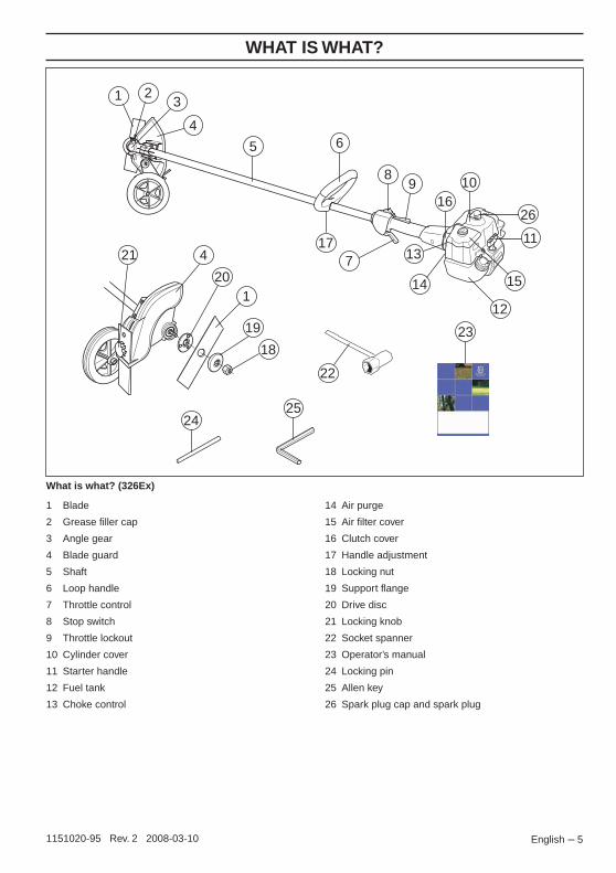
What is what? (326Ex)
1016
8
7
9
65
4
3
1
2
17 11
14
1321
19
20
22
23
2425
18
26
15
1
4
12
1 Blade
2 Grease filler cap
3 Angle gear
4 Blade guard
5 Shaft
6 Loop handle
7 Throttle control
8 Stop switch
9 Throttle lockout
10 Cylinder cover
11 Starter handle
12 Fuel tank
13 Choke control
14 Air purge
15 Air filter cover
16 Clutch cover
17 Handle adjustment
18 Locking nut
19 Support flange
20 Drive disc
21 Locking knob
22 Socket spanner
23 Operator’s manual
24 Locking pin
25 Allen key
26 Spark plug cap and spark plug
English – 51151020-95 Rev. 2 2008-03-10
WHA
T IS
WHA
T?
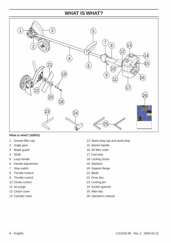
What is what? (326ES)
1312
87
9
6
5
4
31
2
17
15
11
10
26
21
19
20
22
23 24
18
14
25
16
1 Grease filler cap
2 Angle gear
3 Blade guard
4 Shaft
5 Loop handle
6 Handle adjustment
7 Stop switch
8 Throttle lockout
9 Throttle control
10 Choke control
11 Air purge
12 Clutch cover
13 Cylinder cover
14 Spark plug cap and spark plug
15 Starter handle
16 Air filter cover
17 Fuel tank
18 Locking screw
19 Washers
20 Support flange
21 Blade
22 Drive disc
23 Locking pin
24 Socket spanner
25 Allen key
26 Operator’s manual
6 – English 1151020-95 Rev. 2 2008-03-10

GENERAL SAFETY PRECA
UTIONS
Important Personal protective equipment
HEARING PROTECTION
Wear hearing protection that provides adequate noise reduction.
EYE PROTECTION
Always wear approved eye protection. If you use a visor then you must also wear approved protective goggles. Approved protective goggles must comply with standard ANSI Z87.1 in the USA or EN 166 in EU countries.
GLOVES
Gloves should be worn when necessary, e.g., when fitting cutting attachments.
BOOTS
Wear boots with steel toe-caps and non-slip sole.
IMPORTANT!
The machine is only designed for edging lawns.
The only accessories you can operate with this engine unit are the cutting attachments we recommend in the chapter on Technical data.
Never use the machine if you are tired, if you have drunk alcohol, or if you are taking medication that could affect your vision, your judgement or your co-ordination.
Wear personal protective equipment. See instructions under the heading Personal protective equipment.
Never use a machine that has been modified in any way from its original specification.
Never use a machine that is faulty. Carry out the checks, maintenance and service instructions described in this manual. Some maintenance and service measures must be carried out by trained and qualified specialists. See instructions under the heading Maintenance.
All covers, guards and handles must be fitted before starting. Ensure that the spark plug cap and ignition lead are undamaged to avoid the risk of electric shock.
The machine operator must ensure that no people or animals come closer than 15 metres while working. When several operators are working in the same area the safety distance should be at least twice the tree height and no less than 15 metres.
!WARNING! The ignition system of this machine produces an electromagnetic field during operation. This field may under some circumstances interfere with pacemakers. To reduce the risk of serious or fatal injury, we recommend persons with pacemakers to consult their physician and the pacemaker manufacturer before operating this machine.
!WARNING! Running an engine in a confined or badly ventilated area can result in death due to asphyxiation or carbon monoxide poisoning.
!WARNING! Never allow children to use or be in the vicinity of the machine. As the machine is equipped with a spring-loaded stop switch and can be started by low speed and force on the starter handle, even small children under some circumstances can produce the force necessary to start the machine. This can mean a risk of serious personal injury. Therefore remove the spark plug cap when the machine is not under close supervision.
IMPORTANT!
An edger can be a dangerous tool if used incorrectly or carelessly, and can cause serious or fatal injury to the operator or others. It is extremely important that you read and understand the contents of this operator’s manual.
You must use approved personal protective equipment whenever you use the machine. Personal protective equipment cannot eliminate the risk of injury but it will reduce the degree of injury if an accident does happen. Ask your dealer for help in choosing the right equipment.
!WARNING! Listen out for warning signals or shouts when you are wearing hearing protection. Always remove your hearing protection as soon as the engine stops.
English – 71151020-95 Rev. 2 2008-03-10
GENERAL SAFETY PRECAUTIONS
CLOTHINGWear clothes made of a strong fabric and avoid loose clothing that can catch on twigs and branches. Always wear heavy, long pants. Do not wear jewellery, shorts sandals or go barefoot. Secure hair so it is above shoulder level.
FIRST AID KIT
Always have a first aid kit nearby.
Machine′s safety equipmentThis section describes the machine′s safety equipment, its purpose, and how checks and maintenance should be carried out to ensure that it operates correctly. See the ”What is what?” section to locate where this equipment is positioned on your machine.
The life span of the machine can be reduced and the risk of accidents can increase if machine maintenance is not carried out correctly and if service and/or repairs are not carried out professionally. If you need further information please contact your nearest servicing dealer.
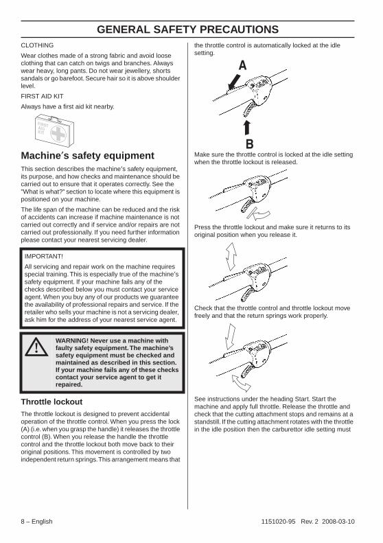
Throttle lockoutThe throttle lockout is designed to prevent accidental operation of the throttle control. When you press the lock (A) (i.e. when you grasp the handle) it releases the throttle control (B). When you release the handle the throttle control and the throttle lockout both move back to their original positions. This movement is controlled by two independent return springs. This arrangement means that
the throttle control is automatically locked at the idle setting.
Make sure the throttle control is locked at the idle setting when the throttle lockout is released.
Press the throttle lockout and make sure it returns to its original position when you release it.
Check that the throttle control and throttle lockout move freely and that the return springs work properly.
See instructions under the heading Start. Start the machine and apply full throttle. Release the throttle and check that the cutting attachment stops and remains at a standstill. If the cutting attachment rotates with the throttle in the idle position then the carburettor idle setting must
IMPORTANT!
All servicing and repair work on the machine requires special training. This is especially true of the machine′s safety equipment. If your machine fails any of the checks described below you must contact your service agent. When you buy any of our products we guarantee the availability of professional repairs and service. If the retailer who sells your machine is not a servicing dealer, ask him for the address of your nearest service agent.
!WARNING! Never use a machine with faulty safety equipment. The machine’s safety equipment must be checked and maintained as described in this section. If your machine fails any of these checks contact your service agent to get it repaired.
8 – English 1151020-95 Rev. 2 2008-03-10

GENERAL SAFETY PRECAUTIONS
be checked. See instructions under the heading Maintenance.Stop switchUse the stop switch to switch off the engine.
Start the engine and make sure the engine stops when you move the stop switch to the stop setting.
Cutting attachment guard
This guard is intended to prevent loose objects from being thrown towards the operator. The guard also protects the operator from accidental contact with the cutting attachment.
Check that the guard is undamaged and not cracked. Replace the guard if it has been exposed to impact or is cracked.
Always use the recommended guard for the cutting attachment you are using. See chapter on Technical data.
Vibration damping system
Your machine is equipped with a vibration damping system that is designed to reduce vibration and make operation easier.
The use of incorrect cutting attachments increases the level of vibration. See instructions under the heading Cutting equipment.
The machine′s vibration damping system reduces the transfer of vibration between the engine unit/cutting equipment and the machine′s handle unit.
Regularly check the vibration damping units for cracks or deformation. Check that the vibration damping element is undamaged and securely attached.
!WARNING! Never use a cutting attachment without an approved guard. See the chapter on Technical data. If an incorrect or faulty guard is fitted this can cause serious personal injury.
!WARNING! Overexposure to vibration can lead to circulatory damage or nerve damage in people who have impaired circulation. Contact your doctor if you experience symptoms of overexposure to vibration. These symptoms include numbness, loss of feeling, tingling, pricking, pain, loss of strength, changes in skin colour or condition. These symptoms normally appear in the fingers, hands or wrists.
English – 91151020-95 Rev. 2 2008-03-10
GENERAL SAFETY PRECAUTIONS
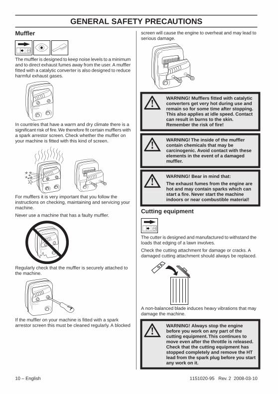
MufflerThe muffler is designed to keep noise levels to a minimum and to direct exhaust fumes away from the user. A muffler fitted with a catalytic converter is also designed to reduce harmful exhaust gases.
In countries that have a warm and dry climate there is a significant risk of fire. We therefore fit certain mufflers with a spark arrestor screen. Check whether the muffler on your machine is fitted with this kind of screen.
For mufflers it is very important that you follow the instructions on checking, maintaining and servicing your machine.
Never use a machine that has a faulty muffler.
Regularly check that the muffler is securely attached to the machine.
If the muffler on your machine is fitted with a spark arrestor screen this must be cleaned regularly. A blocked
screen will cause the engine to overheat and may lead to serious damage.
Cutting equipment
The cutter is designed and manufactured to withstand the loads that edging of a lawn involves.
Check the cutting attachment for damage or cracks. A damaged cutting attachment should always be replaced.
A non-balanced blade induces heavy vibrations that may damage the machine.
!WARNING! Mufflers fitted with catalytic converters get very hot during use and remain so for some time after stopping. This also applies at idle speed. Contact can result in burns to the skin. Remember the risk of fire!
!WARNING! The inside of the muffler contain chemicals that may be carcinogenic. Avoid contact with these elements in the event of a damaged muffler.
!WARNING! Bear in mind that:
The exhaust fumes from the engine are hot and may contain sparks which can start a fire. Never start the machine indoors or near combustible material!
!WARNING! Always stop the engine before you work on any part of the cutting equipment. This continues to move even after the throttle is released. Check that the cutting equipment has stopped completely and remove the HT lead from the spark plug before you start any work on it.
10 – English 1151020-95 Rev. 2 2008-03-10

GENERAL SAFETY PRECAUTIONS
Locking nut (326Ex)The locking nut secures the cutting attachment on the output shaft.
Protect your hand from injury when assembling, use the blade guard as protection when tightening with a socket spanner.
When fitting, tighten the nut in the opposite direction to the direction of rotation of the cutting attachment. To remove it, undo the nut in the same direction as the cutting attachment rotates. (CAUTION! The nut has a left-hand thread.)
Tighten the nut using the socket spanner. 35-50 Nm (3.5-5 kpm).
The nylon lining inside the locking nut must not be so worn that you can turn it by hand. The lining should offer a resistance of at least 1.5 Nm. The nut should be replaced after it has been put on approx. 10 times.
Locking screw (326ES)
The locking screw secures the cutting attachment on the output shaft.
Protect your hand from injury when assembling, use the blade guard as protection when tightening with a socket spanner.
When fitting, tighten the screw in the opposite direction to the direction of rotation of the cutting attachment. To remove it, undo the screw in the same direction as the cutting attachment rotates. (CAUTION! The screw has a left-hand thread.)
Tighten the screw using the socket spanner. 18-25 Nm (1,8-2,5 kpm).
English – 111151020-95 Rev. 2 2008-03-10

ASSEMBLY
Fitting the loop handle
• Position the handle on the shaft. Note that the handle must be mounted below the arrow on the shaft.
• Fit the bolt, securing plate and wing nut as shown in the diagram.
• Tighten the wing nut.
Assembling the angle gear (326Ex)
• Assemble the angle gear back on the suppporting tube. Turn the blade so that the drive shaft engages in the angle gear.
• Position the angle gear so that its slot is aligned with the line on the supporting tube.
• Firmly tighten the screw.
Assembling the angle gear (326ES)
• Assemble the angle gear back on the suppporting tube. Turn the blade so that the drive shaft engages in the angle gear.
• Tighten the two screws.
12 – English 1151020-95 Rev. 2 2008-03-10

ASSEMBLY
Assembling the cutting equipment
Assembling the blade (326Ex)
Fit the blade as follows:
1 Fit the drive disc (A) on the outgoing shaft. Make sure that the edge that fits in the hole of the blade is facing outward.
2 Block the blade rotation by inserting the locking pin in the hole behind the blade guard engaging it in the corresponding hole in the drive disc.
3 Fit the blade (B) on the drive disc.
4 Fit the support flange (C). The support flange must be fitted with its outer edge hard up against the blade.
5 Fit the locking nut (D). CAUTION! The locking nut has a left-hand thread. Tighten the locking nut to a torque of 35-50 Nm (3,5-5 kpm).
6 Remove the locking pin.
CAUTION! Do not forget to remove the locking pin before using the machine.
Assembling the blade (326ES)
Fit the blade as follows:
1 Fit the drive disc (A) on the outgoing shaft. Make sure that the edge that fits in the hole of the blade is facing outward.
2 Block the blade rotation by inserting the locking pin in the hole behind the blade guard engaging it in the corresponding hole in the drive disc.
3 Fit the blade (B) on the drive disc.
4 Fit the support flange (C). The support flange must be fitted with its outer edge hard up against the blade.
5 Fit the two washers (D) and the locking screw (E).
6 Tighten the locking screw to a torque of 18-25 Nm (1,8-2,5 kpm).
7 Remove the locking pin.
CAUTION! Do not forget to remove the locking pin before using the machine.
!WARNING!
When fitting the cutting attachment it is extremely important that the raised section on the drive disc/support flange engages correctly in the centre hole of the cutting attachment. If the cutting attachment is fitted incorrectly it can result in serious and/or fatal personal injury.
!WARNING! Under no circumstances may the edge cutter blade be used without the blade guard fitted. A
BC
DE
English – 131151020-95 Rev. 2 2008-03-10
FUEL HANDLING
Fuel safetyNever start the machine:
1 If you have spilled fuel on it. Wipe off the spillage and allow remaining fuel to evaporate.
2 If you have spilled fuel on yourself or your clothes, change your clothes. Wash any part of your body that has come in contact with fuel. Use soap and water.
3 If the machine is leaking fuel. Check regularly for leaks from the fuel cap and fuel lines.
Transport and storage• Store and transport the machine and fuel so that there
is no risk of any leakage or fumes coming into contact with sparks or naked flames, for example, from electrical machinery, electric motors, electrical relays/switches or boilers.
• When storing and transporting fuel always use approved containers intended for this purpose.
• When storing the machine for long periods the fuel tank must be emptied. Contact your local gas station to find out where to dispose of excess fuel.
• Ensure the machine is cleaned and that a complete service is carried out before long-term storage.
• The transport guard must always be fitted to the cutting attachment when the machine is being transported or in storage.
• In order to prevent unintentional starting of the engine, the spark plug cap must always be removed during long-term storage, if the machine is not under close supervision and when performing all service measures.
FuelCAUTION! The machine is equipped with a two-stroke engine and must always been run using a mixture of gasoline and two-stroke engine oil. It is important to accurately measure the amount of oil to be mixed to ensure that the correct mixture is obtained. When mixing small amounts of fuel, even small inaccuracies can drastically affect the ratio of the mixture.
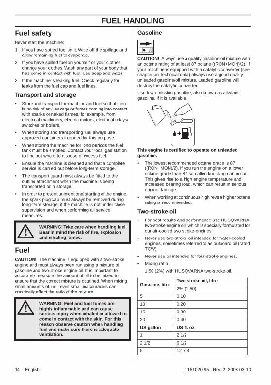
Gasoline
CAUTION! Always use a quality gasoline/oil mixture with an octane rating of at least 87 octane ((RON+MON)/2). If your machine is equipped with a catalytic converter (see chapter on Technical data) always use a good quality unleaded gasoline/oil mixture. Leaded gasoline will destroy the catalytic converter.
Use low-emission gasoline, also known as alkylate gasoline, if it is available.
This engine is certified to operate on unleaded gasoline.
• The lowest recommended octane grade is 87 ((RON+MON)/2). If you run the engine on a lower octane grade than 87 so-called knocking can occur. This gives rise to a high engine temperature and increased bearing load, which can result in serious engine damage.
• When working at continuous high revs a higher octane rating is recommended.
Two-stroke oil• For best results and performance use HUSQVARNA
two-stroke engine oil, which is specially formulated for our air-cooled two stroke-engines.
• Never use two-stroke oil intended for water-cooled engines, sometimes referred to as outboard oil (rated TCW).
• Never use oil intended for four-stroke engines.
• Mixing ratio
1:50 (2%) with HUSQVARNA two-stroke oil.
!WARNING! Take care when handling fuel. Bear in mind the risk of fire, explosion and inhaling fumes.
!WARNING! Fuel and fuel fumes are highly inflammable and can cause serious injury when inhaled or allowed to come in contact with the skin. For this reason observe caution when handling fuel and make sure there is adequate ventilation.
Gasoline, litreTwo-stroke oil, litre
2% (1:50)
5 0,10
10 0,20
15 0,30
20 0,40
US gallon US fl. oz.
1 2 1/2
2 1/2 6 1/2
5 12 7/8
14 – English 1151020-95 Rev. 2 2008-03-10
FUEL HANDLING
Mixing• Always mix the gasoline and oil in a clean containerintended for fuel.
• Always start by filling half the amount of the gasoline to be used. Then add the entire amount of oil. Mix (shake) the fuel mixture. Add the remaining amount of gasoline.
• Mix (shake) the fuel mixture thoroughly before filling the machine’s fuel tank.
• Do not mix more than one month’s supply of fuel at a time.
• If the machine is not used for some time the fuel tank should be emptied and cleaned.
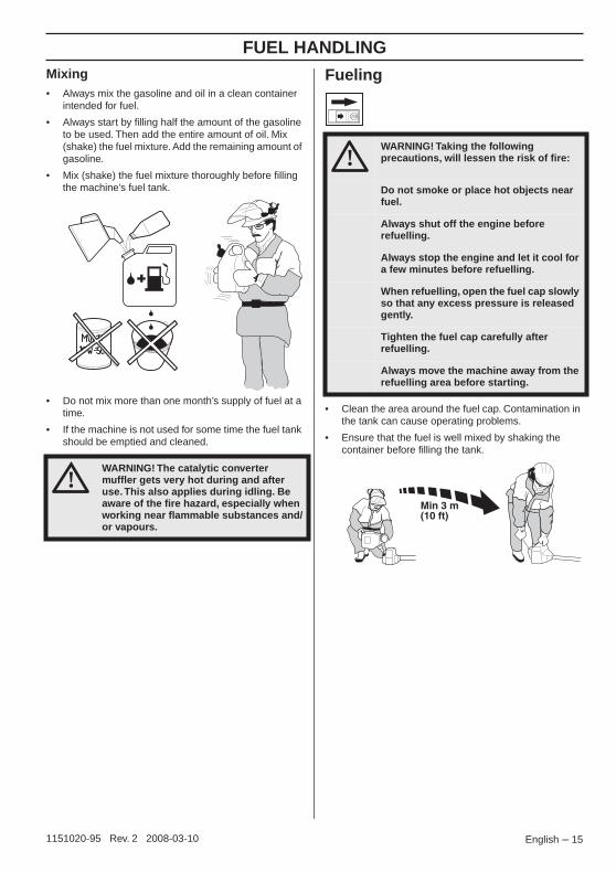
Fueling
• Clean the area around the fuel cap. Contamination in the tank can cause operating problems.
• Ensure that the fuel is well mixed by shaking the container before filling the tank.
!WARNING! The catalytic converter muffler gets very hot during and after use. This also applies during idling. Be aware of the fire hazard, especially when working near flammable substances and/or vapours.
!WARNING! Taking the following precautions, will lessen the risk of fire:
Do not smoke or place hot objects near fuel.
Always shut off the engine before refuelling.
Always stop the engine and let it cool for a few minutes before refuelling.
When refuelling, open the fuel cap slowly so that any excess pressure is released gently.
Tighten the fuel cap carefully after refuelling.
Always move the machine away from the refuelling area before starting.
English – 151151020-95 Rev. 2 2008-03-10

STARTING AND STOPPING
Check before starting
• Check that the support flange is not cracked due to fatigue or due to being tightened too much. Discard the support flange if it is cracked.
• Ensure the locking nut has not lost its captive force. The nut lock should have a locking force of at least 1.5 Nm. The tightening torque of the locking nut should be 35-50 Nm. (326Ex)
• Check that the blade and the blade guard are not damaged or cracked. Replace the blade or blade guard if it has been exposed to impact or if it is cracked.
• Never use the machine without a guard nor with a defective guard.
• All covers must be correctly fitted and undamaged before you start the machine.
Starting and stopping
StartingPrimer bulb: Press the air purge repeatedly until fuel begins to fill the bulb. The bulb need not be completely filled.
Choke: Set the choke control in the choke position.
Hold the body of the machine on the ground using your left hand (CAUTION! Not with your foot!). Grip the starter handle, slowly pull out the cord with your right hand until you feel some resistance (the starter pawls grip), now quickly and powerfully pull the cord. Never wrap the starter cord around your hand
!WARNING! The complete clutch cover and shaft must be fitted before the machine is started, otherwise the clutch can come loose and cause personal injury.
Always move the machine away from the refuelling area before starting. Place the machine on a flat surface. Ensure the cutting attachment cannot come into contact with any object.
Make sure no unauthorised persons are in the working area, otherwise there is a risk of serious personal injury. The safety distance is 15 metres.
!WARNING! When the engine is started with the choke in either the choke or start throttle positions the cutting attachment will start to rotate immediately.
16 – English 1151020-95 Rev. 2 2008-03-10
STARTING AND STOPPING
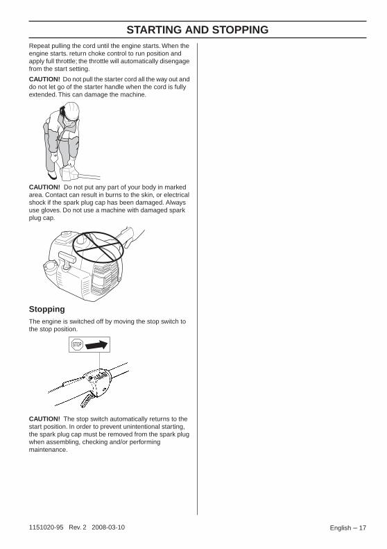
Repeat pulling the cord until the engine starts. When the engine starts. return choke control to run position and apply full throttle; the throttle will automatically disengage from the start setting.CAUTION! Do not pull the starter cord all the way out and do not let go of the starter handle when the cord is fully extended. This can damage the machine.
CAUTION! Do not put any part of your body in marked area. Contact can result in burns to the skin, or electrical shock if the spark plug cap has been damaged. Always use gloves. Do not use a machine with damaged spark plug cap.
StoppingThe engine is switched off by moving the stop switch to the stop position.
CAUTION! The stop switch automatically returns to the start position. In order to prevent unintentional starting, the spark plug cap must be removed from the spark plug when assembling, checking and/or performing maintenance.
English – 171151020-95 Rev. 2 2008-03-10
WORKING TECHNIQUES
General working instructions
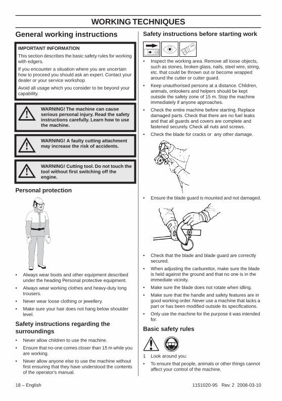
Personal protection
• Always wear boots and other equipment described under the heading Personal protective equipment.
• Always wear working clothes and heavy-duty long trousers.
• Never wear loose clothing or jewellery.
• Make sure your hair does not hang below shoulder level.
Safety instructions regarding the surroundings• Never allow children to use the machine.
• Ensure that no-one comes closer than 15 m while you are working.
• Never allow anyone else to use the machine without first ensuring that they have understood the contents of the operator’s manual.
Safety instructions before starting work
• Inspect the working area. Remove all loose objects, such as stones, broken glass, nails, steel wire, string, etc. that could be thrown out or become wrapped around the cutter or cutter guard.
• Keep unauthorised persons at a distance. Children, animals, onlookers and helpers should be kept outside the safety zone of 15 m. Stop the machine immediately if anyone approaches.
• Check the entire machine before starting. Replace damaged parts. Check that there are no fuel leaks and that all guards and covers are complete and fastened securely. Check all nuts and screws.
• Check the blade for cracks or any other damage.
• Ensure the blade guard is mounted and not damaged.
• Check that the blade and blade guard are correctly secured.
• When adjusting the carburettor, make sure the blade is held against the ground and that no one is in the immediate vicinity.
• Make sure the blade does not rotate when idling.
• Make sure that the handle and safety features are in good working order. Never use a machine that lacks a part or has been modified outside its specifications.
• Only use the machine for the purpose it was intended for.
Basic safety rules
1 Look around you:
• To ensure that people, animals or other things cannot affect your control of the machine.
IMPORTANT INFORMATION
This section describes the basic safety rules for working with edgers.
If you encounter a situation where you are uncertain how to proceed you should ask an expert. Contact your dealer or your service workshop.
Avoid all usage which you consider to be beyond your capability.
!WARNING! The machine can cause serious personal injury. Read the safety instructions carefully. Learn how to use the machine.
!WARNING! A faulty cutting attachment may increase the risk of accidents.
!WARNING! Cutting tool. Do not touch the tool without first switching off the engine.
18 – English 1151020-95 Rev. 2 2008-03-10

WORKING TECHNIQUES
• To ensure that people, animals, etc., do not come intocontact with the cutting attachment or loose objects that are thrown out by the cutting attachment.
• CAUTION! Do not use the machine unless you are able to call for help in the event of an accident.
2 Do not use the machine in bad weather, such as dense fog, heavy rain, strong wind, intense cold, etc.
3 Make sure you can move and stand safely. Check the area around you for possible obstacles (roots, rocks, branches, ditches, etc.) in case you have to move suddenly. Take great care when working on sloping ground.
4 The engine must be switched off before moving.
5 Never put the machine down with the engine running unless you have it in clear sight.
Basic working techniques
Safety instructions while working
• Always ensure you have a safe and stable working position.
• Always hold the machine with both hands. Hold the machine on the right side of your body.
• Use your right hand to control the throttle setting.
• Make sure that your hands and feet do not come near the cutting attachment when the engine is running.
• When the engine is switched off, keep your hands and feet away from the cutting attachment until it has stopped completely.
• Always carry out edging at full throttle.
• Always keep the blade close to the ground.
• Always slow the engine to idle speed after each working operation. Long periods at full throttle without any load on the engine (i.e. without the resistance that the cutting attachment exerts on the engine when you are using the machine) can lead to serious engine damage.
• Be especially careful when pulling the edger towards you during work.
• If any foreign object is hit or if vibrations occur stop the machine immediately. Disconnect the HT lead from the spark plug. Check that the machine is not damaged. Repair any damage.
!WARNING! Sometimes grass or stones can get trapped in the cutter guard and cutter. Always stop the engine before cleaning.
!WARNING! Watch out for thrown objects. Always wear approved eye protection. Never lean over the cutting attachment guard. Stones, rubbish, etc. can be thrown up into the eyes causing blindness or serious injury.
English – 191151020-95 Rev. 2 2008-03-10
WORKING TECHNIQUES
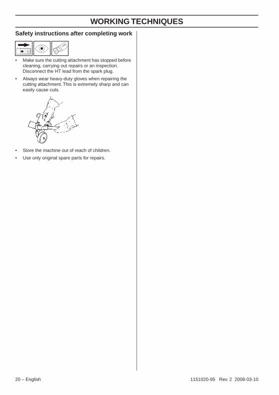
Safety instructions after completing work• Make sure the cutting attachment has stopped before cleaning, carrying out repairs or an inspection. Disconnect the HT lead from the spark plug.
• Always wear heavy-duty gloves when repairing the cutting attachment. This is extremely sharp and can easily cause cuts.
• Store the machine out of reach of children.
• Use only original spare parts for repairs.
20 – English 1151020-95 Rev. 2 2008-03-10

MAINTENANCE
CarburetorYour Husqvarna product has been designed and manufactured to specifications that reduce harmful emissions. After the engine has used 8-10 tanks of fuel the engine will be run-in. To ensure that it continues to run at peak performance and to minimise harmful exhaust emissions after the running-in period, ask your dealer/service workshop (who will have a rev counter at their disposal) to adjust your carburettor.
Function
• The carburetor governs the engine’s speed via the throttle control. Air and fuel are mixed in the carburetor. The air/fuel mixture is adjustable. Correct adjustment is essential to get the best performance from the machine.
• The setting of the carburetor means that the engine is adapted to local conditions, for example, the climate, altitude, fuel and the type of 2-stroke oil.
• The carburetor has three adjustment controls:
L = Low speed jet
H = High speed jet
T = Idle adjustment screw
• The L and H-jets are used to adjust the supply of fuel to match the rate that air is admitted, which is controlled with the throttle. If they are screwed clockwise the air/fuel ratio becomes leaner (less fuel) and if they are turned anti-clockwise the ratio becomes richer (more fuel). A lean mixture gives a higher engine speed and a rich mixture gives a lower engine speed.
• The T-screw regulates the throttle setting at idle speed. If the T-screw is turned clockwise this gives a higher idle speed; turning it anti-clockwise gives a lower idle speed.
Basic setting• The basic carburetor settings are adjusted during
testing at the factory. The basic setting is richer than the optimal setting and should be maintained for the first few hours the machine is in use. The carburettor should then be finely adjusted. Fine adjustment should be carried out by a skilled technician.
CAUTION! If the cutting attachment rotates when the engine is idling the idle adjustment screw T should be turned anti-clockwise until the cutting attachment stops.
Rec. idle speed: 2700 rpm
Recommended max. speed: See the Technical data section.
Fine adjustment• When the machine has been ”run-in” the carburetor
should be finely adjusted. The fine adjustment should be carried out by a qualified person. First adjust the L-jet, then the idling screw T and then the H-jet.
Conditions• Before any adjustments are made, make sure that the
air filter is clean and the air filter cover is fitted. If you adjust the carburettor when the air filter is dirty it will result in a leaner mixture when the filter is finally cleaned. This can lead to serious engine damage.
• Carefully turn both jets, L and H, so that they are midway between fully screwed in and fully screwed out.
• Do not attempt to adjust the L and H jets beyond either stop as this could cause damage.
• Now start the machine according to the starting instructions and let it warm up for 10 minutes.
CAUTION! If the cutting attachment rotates when the engine is idling the idle adjustment screw T should be turned anti-clockwise until the cutting attachment stops.
!WARNING! The complete clutch cover and shaft must be fitted before the machine is started, otherwise the clutch can come loose and cause personal injury.
!WARNING! If the idle speed cannot be adjusted so that the cutting attachment stops, contact your dealer/service workshop. Do not use the machine until it has been correctly adjusted or repaired.
English – 211151020-95 Rev. 2 2008-03-10
MAINTENANCE
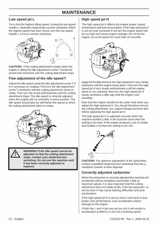
Low speed jet LTry to find the highest idling speed, turning the low speed needle L clockwise respectively counter-clockwise. When the highest speed has been found, turn the low speed needle L 1/4 turn counter-clockwise.CAUTION! If the cutting attachment rotates when the engine is idling the idle adjustment screw T should be turned anti-clockwise until the cutting attachment stops.
Fine adjustment of the idle speed TAdjust the idle speed using the idle adjustment screw T, if it is necessary to readjust. First turn the idle adjustment screw T clockwise until the cutting attachment starts to rotate. Then turn the screw anticlockwise until the cutting attachment stops. The idle speed is correctly adjusted when the engine will run smoothly in every position. The idle speed should also be well below the speed at which the cutting attachment starts to rotate.
High speed jet HThe high speed jet H affects the engine power, speed, temperature and fuel consumption. If the high speed jet H is set too lean (screwed in too far) the engine speed will be too high and cause engine damage. Do not let the engine run at full speed for more than 10 seconds.
Apply full throttle and turn the high speed jet H very slowly clockwise until the engine slows down. Then turn the high speed jet H very slowly anticlockwise until the engine starts to run unevenly. Now turn the high speed jet H slowly clockwise a little way until the engine runs smoothly.
Note that the engine should not be under load when you adjust the high speed jet H. You should therefore remove the cutting attachment, nut, support flange and drive disc before adjusting the high speed jet H.
The high speed jet H is adjusted correctly when the machine burbles a little. If the machine races then the setting is too lean. If the engine produces a lot of smoke and burbles a lot then the setting is too rich.
CAUTION! For optimum adjustment of the carburettor, contact a qualified dealer/service workshop that has a revolution counter at their disposal.
Correctly adjusted carburetorWhen the carburetor is correctly adjusted the machine will accelerate without hesitation and burble a little at maximum speed. It is also important that the cutting attachment does not rotate at idle. If the low speed jet L is set too lean it may cause starting difficulties and poor acceleration.
If the high speed jet H is set too lean it will result in less power, less performance, poor acceleration and/or damage to the engine.
If both the L and H jets are set too rich it will results in acceleration problems or too low a working speed.
!WARNING! If the idle speed cannot be adjusted so that the cutting attachment stops, contact your dealer/service workshop. Do not use the machine until it has been correctly adjusted or repaired.
L
+ 1/4
H
22 – English 1151020-95 Rev. 2 2008-03-10
MAINTENANCE
Muffler
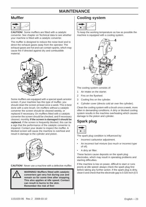
CAUTION! Some mufflers are fitted with a catalytic converter. See chapter on Technical data to see whether your machine is fitted with a catalytic converter.
The muffler is designed to reduce the noise level and to direct the exhaust gases away from the operator. The exhaust gases are hot and can contain sparks, which may cause fire if directed against dry and combustible material.
Some mufflers are equipped with a special spark arrestor screen. If your machine has this type of muffler, you should clean the screen at least once a week. This is best done with a wire brush. On mufflers without a catalytic converter the screen should be cleaned weekly, or replaced if necessary. On mufflers fitted with a catalytic converter the screen should be checked, and if necessary cleaned, monthly. If the screen is damaged it should be replaced. If the screen is frequently blocked, this can be a sign that the performance of the catalytic converter is impaired. Contact your dealer to inspect the muffler. A blocked screen will cause the machine to overheat and result in damage to the cylinder and piston.
CAUTION! Never use a machine with a defective muffler.
Cooling system
To keep the working temperature as low as possible the machine is equipped with a cooling system.
The cooling system consists of:
1 Air intake on the starter.
2 Fins on the flywheel.
3 Cooling fins on the cylinder.
4 Cylinder cover (directs cold air over the cylinder).
Clean the cooling system with a brush once a week, more often in demanding conditions. A dirty or blocked cooling system results in the machine overheating which causes damage to the piston and cylinder.
Spark plug
The spark plug condition is influenced by:
• Incorrect carburetor adjustment.
• An incorrect fuel mixture (too much or incorrect type of oil).
• A dirty air filter.
These factors cause deposits on the spark plug electrodes, which may result in operating problems and starting difficulties.
If the machine is low on power, difficult to start or runs poorly at idle speed: always check the spark plug first before taking any further action. If the spark plug is dirty, clean it and check that the electrode gap is 0.020 inch (0.5 !
WARNING! Mufflers fitted with catalytic converters get very hot during use and remain so for some time after stopping. This also applies at idle speed. Contact can result in burns to the skin. Remember the risk of fire!
1
23
4
English – 231151020-95 Rev. 2 2008-03-10

MAINTENANCE
mm). The spark plug should be replaced after about a month in operation or earlier if necessary.CAUTION! Always use the recommended spark plug type! Use of the wrong spark plug can damage the piston/cylinder. Check that the spark plug is fitted with a suppressor.
Air filter
The air filter must be regularly cleaned to remove dust and dirt in order to avoid:
• Carburettor malfunctions
• Starting problems
• Loss of engine power
• Unnecessary wear to engine parts
• Excessive fuel consumption.
Clean the filter every 25 hours, or more regularly if conditions are exceptionally dusty.
Cleaning the air filterRemove the air filter cover and take out the filter. Wash it clean in warm, soapy water. Ensure that the filter is dry before refitting it.
An air filter that has been in use for a long time cannot be cleaned completely. The filter must therefore be replaced with a new one at regular intervals. A damaged air filter must always be replaced.
If the machine is used in dusty conditions the air filter should be soaked in oil. See instructions under the heading Oiling the air filter.
Oiling the air filter
Always use HUSQVARNA filter oil, art. no. 531 00 92-48. The filter oil contains a solvent to make it spread evenly through the filter. You should therefore avoid skin contact.
Put the filter in a plastic bag and pour the filter oil over it. Knead the plastic bag to distribute the oil. Squeeze the excess oil out of the filter inside the plastic bag and pour off the excess before fitting the filter to the machine. Never use common engine oil. This would drain through the filter quite quickly and collect in the bottom.
Angle gear
The angle gear is filled with a sufficient quantity of grease at the factory. However, before using the machine you should check that the angle gear is filled to 3/4 with grease. Use HUSQVARNA special grease.
The grease in the bevel gear does not normally need to be changed except if repairs are carried out.
326Ex 326ES
24 – English 1151020-95 Rev. 2 2008-03-10

MAINTENANCE
Lubricating the flexible drive shaft (326Ex)
Inside the hollow drive shaft of the edger is a flexible drive shaft. This flexible drive shaft should be regularly lubricated every 25 hours in operation. Loosen the two screws on the angle gear and remove it. The flexible drive shaft is easily removed from the hollow shaft by taking a firm grip on the shaft end. Lubricate the entire length of the flexible drive shaft and reinsert it in the hollow drive shaft. Turn the shaft while inserting it so that it correctly engages in the clutch. Refit the angle gear on the hollow drive shaft and tighten the two screws.
Adjusting the edger’s cutting depth (326Ex)
The cutting depth must be adjusted before starting work.
• Loosen the locking knob (A) and rotate the guard by moving the locking knob forwards or backwards. If the locking knob is moved forwards (away from the machine) the cutting depth is increased. If the locking knob is moved backwards (towards the machine) the cutting depth is reduced.
• Set the desired cutting depth.
• Lock the locking knob.
Adjusting the edger’s cutting depth (326ES)
The cutting depth must be adjusted before starting work.
• Loosen the wing nut.
• Set the desired cutting depth.
• Tighten the wing nut.
A
CAUTION! Use only HUSQVARNA replacement parts. Use of other brands of replacement parts can cause damage to your unit or injury to the operator or others. Your warranty does not cover damage or liability caused by the use of accessories and/or attachments not specifically recommended by HUSQVARNA.
English – 251151020-95 Rev. 2 2008-03-10

MAINTENANCE
Maintenance scheduleThe following is a list of the maintenance that must be performed on the machine. Most of the items are described in the Maintenance section.
Maintenance Daily maintenance
Weekly maintenance
Monthly maintenance
Clean the outside of the machine. X
Make sure the throttle trigger lock and the throttle function correctly from a safety point of view.
X
Check that the stop switch works correctly. X
Check that the cutting attachment does not rotate at idle. X
Clean the air filter. Replace if necessary. X
Check that the guard is undamaged and not cracked. Replace the guard if it has been exposed to impact or is cracked.
X
Check the blade for cracks and chips or damage. Replace if necessary.
X
Check that the locking nut of the cutting equipment is tighten correctly. (326Ex)
X
Check that the locking screw of the cutting equipment is tightened correctly. (326ES)
Check that nuts and screws are tight. X
Check that there are no fuel leaks from the engine, tank or fuel lines. X
Check the starter and starter cord. X
Check that the vibration damping elements are not damaged. X
Clean the outside of the spark plug. Remove it and check the electrode gap. Adjust the gap to 0.5 mm (.20”), or replace the spark plug. Check that the spark plug is fitted with a suppressor.
X
Clean the machine’s cooling system. X
Clean or replace the spark arrestor screen on the muffler (only applies to mufflers without a catalytic converter).
X
Clean the outside of the carburettor and the space around it. X
Check that the angle gear is filled three-quarters full with lubricant. Fill if necessary using special grease.
X
The flexible drive shaft must be lubricated every 25 working hours or more frequently. (326Ex)
X
Check the fuel filter from contamination and the fuel hose from cracks or other defects. Replace if necessary.
X
Check all cables and connections. X
Check the clutch, clutch springs and the clutch drum for wear. Replace if necessary by an autorized service workshop.
X
Replace the spark plug. Check that the spark plug is fitted with a suppressor.
X
Check and clean the spark arrestor screen on the muffler (only applies to mufflers fitted with a catalytic converter).
X
Check and if necessary, clean the exhaust port of cylinder from carbon deposits.
X
26 – English 1151020-95 Rev. 2 2008-03-10
TECHNICAL DATA
Technical data
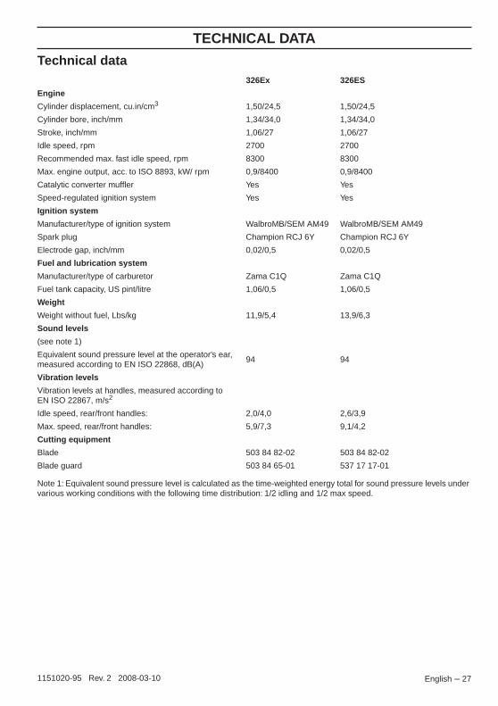
Note 1: Equivalent sound pressure level is calculated as the time-weighted energy total for sound pressure levels under various working conditions with the following time distribution: 1/2 idling and 1/2 max speed.
326Ex 326ES
Engine
Cylinder displacement, cu.in/cm3 1,50/24,5 1,50/24,5
Cylinder bore, inch/mm 1,34/34,0 1,34/34,0
Stroke, inch/mm 1,06/27 1,06/27
Idle speed, rpm 2700 2700
Recommended max. fast idle speed, rpm 8300 8300
Max. engine output, acc. to ISO 8893, kW/ rpm 0,9/8400 0,9/8400
Catalytic converter muffler Yes Yes
Speed-regulated ignition system Yes Yes
Ignition system
Manufacturer/type of ignition system WalbroMB/SEM AM49 WalbroMB/SEM AM49
Spark plug Champion RCJ 6Y Champion RCJ 6Y
Electrode gap, inch/mm 0,02/0,5 0,02/0,5
Fuel and lubrication system
Manufacturer/type of carburetor Zama C1Q Zama C1Q
Fuel tank capacity, US pint/litre 1,06/0,5 1,06/0,5
Weight
Weight without fuel, Lbs/kg 11,9/5,4 13,9/6,3
Sound levels
(see note 1)
Equivalent sound pressure level at the operator’s ear, measured according to EN ISO 22868, dB(A)
94 94
Vibration levels
Vibration levels at handles, measured according to EN ISO 22867, m/s2
Idle speed, rear/front handles: 2,0/4,0 2,6/3,9
Max. speed, rear/front handles: 5,9/7,3 9,1/4,2
Cutting equipment
Blade 503 84 82-02 503 84 82-02
Blade guard 503 84 65-01 537 17 17-01
English – 271151020-95 Rev. 2 2008-03-10

FEDERAL AND CALIFORNIA EMISSIONS CONTROL WARRANTY STATEMENT
YOUR WARRANTY RIGHTS AND OBLIGATIONSThe EPA (U.S. Environmental Protection Agency), CARB (California Air Resources Board), Environment Canada and Husqvarna Forest & Garden are pleased to explain the emissions control system’s warranty on your 2007 and later small off-road engine. In U.S. and Canada, new equipment that use small off-road engines must be designed, built, and equipped to meet the applicable Federal or Californian stringent anti-smog standards. Husqvarna Forest & Garden must warrant the emissions control system on your small off-road engine for the period listed below provided there has been no abuse, neglect or improper maintenance of your equipment. Your emissions control system may include parts such as the carburetor, ignition system, catalytic converter, fuel tank, filters and other associated components. Also, included may be hoses, belts, connectors, sensors, and other emission-related assemblies. Where a warrantable condition exists, Husqvarna Forest & Garden will repair your small off-road engine at no cost to you including diagnosis, parts and labor.
MANUFACTURER′S WARRANTY COVERAGEThe emissions control system is warranted for two years. If any emissions-related part on your equipment is defective, the part will be repaired or replaced by Husqvarna Forest & Garden.
OWNER′S WARRANTY RESPONSIBILITIES• As the small off-road engine owner, you are
responsible for performance of the required maintenance listed in your operator’s manual. Husqvarna Forest & Garden recommends that you retain all receipts covering maintenance on your small off-road engine, but Husqvarna Forest & Garden cannot deny warranty solely for the lack of receipts or your failure to ensure the performance of all scheduled maintenance.
• As the small off-road engine owner, you should however be aware that Husqvarna Forest & Garden may deny you warranty coverage if your small off-road engine or a part has failed due to abuse, neglect, or improper maintenance or unapproved modifications.
• You are responsible for presenting your small off-road engine to a Husqvarna Forest & Garden distribution center or service center as soon as the problem exists. The warranty repairs should be completed in a reasonable amount of time, not to exceed 30 days. If you have any questions regarding your warranty coverage, you should contact Husqvarna Forest & Garden at 1-800-487-5963.
WARRANTY COMMENCEMENT DATEThe warranty period begins on the date the engine or equipment is delivered to an ultimate purchaser.
LENGTH OF COVERAGEHusqvarna Forest & Garden warrants to the ultimate purchaser and each subsequent owner that the engine or equipment is designed, built, and equipped so as to conform with all applicable regulations adopted by EPA and CARB, and is free from defects in materials and workmanship that causes the failure of a warranted part for a period of two years.
WHAT IS COVEREDREPAIR OR REPLACEMENT OF PARTS Repair or replacement of any warranted part under the warranty must be performed at no charge to the owner at a warranty station. Warranty services or repairs will be provided at all Husqvarna Forest & Garden distribution centers that are franchised to service the subject engines. Throughout the emissions warranty period of two years, Husqvarna Forest & Garden must maintain a supply of warranted parts sufficient to meet the expected demand for such parts.
WARRANTY PERIOD Any warranted part that is scheduled for replacement as required in the maintenance schedule, is warranted for the period of time prior to the first scheduled replacement point for that part. If the part fails prior to the first scheduled replacement, the part will be repaired or replaced by Husqvarna Forest & Garden at no cost. Any such part repaired or replaced under warranty is warranted for the remainder of the period prior to the first scheduled replacement point for the part. Any warranted part that is not scheduled for replacement as required in the maintenance schedule, is warranted for two years. If any such part fails during the period of warranty coverage, it will be repaired and replaced by Husqvarna Forest & Garden at no cost. Any such part repaired or replaced under the warranty is warranted for the remaining warranty period. Any warranted part that is scheduled only for regular inspection in the maintenance schedule will be warranted for a period of two years. A statement in such written instructions to the effect of ”repair or replace as necessary” will not reduce the period of warranty coverage. Any such part repaired or replaced under warranty will be warranted for the remaining warranty period.
DIAGNOSIS The owner must not be charged for diagnostic labor that leads to the determination that a warranted part is in fact defective, provided that such diagnostic work is performed at a warranty station.
CONSEQUENTIAL DAMAGES Husqvarna Forest & Garden is liable for damages to other engine components proximately caused by a failure under warranty of any warranted part.
28 – English 1151020-95 Rev. 2 2008-03-10

FEDERAL AND CALIFORNIA EMISSIONS CONTROL WARRANTY STATEMENT
EMISSION WARRANTY PARTS LIST1 Carburetor and internal parts
2 Intake pipe, airfilter holder and carburetor bolts.
3 Airfilter and fuelfilter covered up to maintenance schedule.
4 Spark Plug, covered up to maintenance schedule
5 Ignition Module
6 Muffler with catalytic converter
7 Fuel tank
WHAT IS NOT COVEREDAll failures caused by abuse, neglect or improper maintenance are not covered.
ADD -ON OR MODIFIED PARTS
Add-on or modified parts that are not exempted by CARB or EPA may not be used. The use of any non-exempted add-on or modified parts will be grounds for disallowing a warranty claim. Husqvarna Forest & Garden will not be liable to warrant failures of warranted parts caused by the use of a non-exempted add-on or modified part.
HOW TO FILE A CLAIMIf you have any questions regarding your warranty rights and responsibilities, you should contact your nearest authorized servicing dealer or call Husqvarna Forest & Garden at 1-800-487-5963.
WHERE TO GET WARRANTY SERVICEWarranty services or repairs are provided through all Husqvarna Forest & Garden authorized servicing dealers.
MAINTENANCE, REPLACEMENT AND REPAIR OF EMISSION-RELATED PARTSAny replacement part may be used in the performance of any warranty maintenance or repairs and must be provided without charge to the owner. Such use will not reduce the warranty obligations of the manufacturer.
MAINTENANCE STATEMENTThe owner is responsible for the performance of all required maintenance, as defined in the operator’s manual.
English – 291151020-95 Rev. 2 2008-03-10

SECT
ION
1: L
IMIT
ED W
ARRA
NTY
Husq
varn
a Fo
rest
& Ga
rden
Com
pany
(“Hu
sqva
rna”
) war
rant
s Hus
qvar
na p
rodu
ct to
the
origi
nal p
urch
aser
to b
e fre
e fro
mde
fects
in m
ater
ial a
nd w
orkm
ansh
ip fro
m th
e da
te o
f pur
chas
e fo
r the
“War
rant
y Per
iod” o
f the
pro
duct
as se
t for
th b
elow:
Life
time
War
rant
y (P
arts
and
Lab
or):
All ti
ller t
ines a
nd tr
imm
er sh
afts
again
st br
eaka
ge. P
roof
of p
urch
ase
requ
ired.
Life
time
War
rant
y (“
PART
S ON
LY” a
fter i
nitia
l war
rant
y ex
pira
tion)
:Ign
ition
coils
and
mod
ules o
n ha
ndhe
ld pr
oduc
t.Pr
oof o
f pur
chas
e re
quire
d.W
ARRA
NTY
SCHE
DULE
FOR
TUR
F CA
RE E
quip
men
t - Z
ero
Turn
Rid
ers
(New
war
rant
y app
lies t
o un
its so
ld af
ter A
ugus
t 1, 2
005.
Also
app
lies t
o un
its fa
ctory
-equ
ipped
with
R.O
.P.S.
EZ Z
ero
Turn
Rid
ers:
3 ye
ar co
nsum
er w
arra
nty o
r 600
hou
rs o
f use
(whe
n us
ed so
lely a
t the
own
er’s
resid
ence
.)EZ
& M
Z Z
ero
Turn
Rid
ers:
1 ye
ar co
mm
ercia
l war
rant
y or 6
00 h
ours
of u
se.
iZ, L
Z &
BZ Z
ero
Turn
Rid
ers:
5 ye
ar co
nsum
er w
arra
nty o
r 1,50
0 ho
urs o
f use
.iZ
, LZ
& BZ
Zer
o Tu
rn R
ider
s:5
year
com
mer
cial w
arra
nty o
r 1,5
00 h
ours
of u
se.
3 Ye
ar o
r 1,5
00 H
our C
omm
erci
al U
se W
arra
nty:
spind
les o
n ze
ro tu
rn ri
ders
, hyd
rauli
c pum
ps a
nd w
heel
mot
ors.
War
rant
y Sch
edule
for T
urf C
are
Walk
Beh
ind U
nits -
W, W
G &
WH
Zero
Tur
n Ri
ders
- 3
year
cons
umer
and
com
mer
cial
warra
nty.
New
warra
nty a
pplie
s to
units
sold
afte
r Aug
ust 1
, 200
5. A
lso a
pplie
s to
units
facto
ry-e
quipp
ed w
ith R
.O.P.
S.2
Year
COM
MER
CIAL
and
CONS
UMER
War
rant
y:all
Hus
qvar
na g
roun
d-en
gagin
g co
mm
ercia
l equ
ipmen
t.W
ARRA
NTY
SCHE
DULE
FOR
CON
SUM
ER T
URF
CARE
EQU
IPM
ENT:
2 Ye
ar C
onsu
mer
War
rant
y:Au
tom
atic
mow
er, a
ll Res
ident
ial Z
ero
Turn
Ride
rs, a
ll law
n, ya
rd a
nd g
arde
n tra
ctors
, all
nonc
omm
ercia
l walk
beh
ind m
ower
s, till
ers,
snow
blow
ers,
electr
ical p
rodu
cts a
nd p
ower
-ass
ist co
llecti
on sy
stem
s for
no
ncom
mer
cial, n
onpr
ofes
siona
l, non
institu
tiona
l or n
oninc
ome
prod
ucing
use
, exc
ept a
s her
ein st
ated
. All c
onsu
mer
pr
oduc
t use
mus
t hav
e be
en lim
ited
to th
e ow
ner’s
resid
ence
.
WAR
RANT
YSC
HEDU
LE F
OR C
ONSU
MER
FOR
EST
& GA
RDEN
EQU
IPM
ENT :
2 Ye
ar C
onsu
mer
War
rant
y: a
ll con
sum
er ch
ain sa
ws, t
rimm
ers,
brus
hcut
ters
, clea
ring
saws
, han
dheld
blow
ers,
back
pack
blowe
rs, h
edge
trim
mer
s, an
d ele
ctrica
l pro
ducts
for n
onco
mm
ercia
l, non
prof
essio
nal, n
onins
titutio
nal o
r non
incom
epr
oduc
ing u
se, e
xcep
t as h
erein
stat
ed. A
ll con
sum
er p
rodu
ct us
e m
ust h
ave
been
limite
d to
the
owne
r’s re
siden
ce.
2 Ye
ar o
r 2,0
00 H
our P
ower
train
& 1
Yea
r or 1
,000
Hou
r Bod
y W
arra
nty:
Husq
varn
a Ut
ility V
ehicl
es.
1 Ye
ar W
arra
nty:
Powe
r cut
ters
, stu
mp
grind
er, p
ole p
rune
rs a
nd p
ole sa
ws fo
r non
-com
mer
cial, n
on-p
rofe
ssion
al,no
ninsti
tutio
nal, n
on-m
unici
pality
or n
on-in
com
e pr
oduc
ing u
se. A
ll 300
serie
s trim
mer
s, br
ushc
utte
rs, c
learin
g sa
ws,
hove
ring
trim
mer
s, sti
ck e
dger
s, ba
ckpa
ck b
lower
s, ha
nd h
eld b
lower
s, he
dge
trim
mer
s, po
wer-a
ssist
colle
ction
syste
ms f
orco
mm
ercia
l, ins
titutio
nal, p
rofe
ssion
al or
inco
me
prod
ucing
pur
pose
s or u
se.
1 Ye
ar C
ondi
tiona
l Com
pone
nt W
arra
nty:
Chain
saw
cran
ksha
fts fo
r com
mer
cial/p
rofe
ssion
al us
e (p
arts
and
labor
).Saw
mus
t be
oper
ated
with
Hus
qvar
na X
P2
cycle
oil.
90 D
ay C
omm
erci
al W
arra
nty:
Auto
mat
ic m
ower
, cha
in sa
ws, 1
00 se
ries t
rimm
ers,
powe
r cut
ters
, stu
mp
grind
ers,
pole
saws
, pole
pru
ners
, sno
w th
rowe
rs, m
odel
serie
s 580
& 6
00 w
alk-b
ehind
mow
ers,
or a
ny H
usqv
arna
pro
duct
used
for
com
mer
cial, i
nstitu
tiona
l, pro
fess
ional,
mun
icipa
lity o
r inc
ome
prod
ucing
pur
pose
s or u
se e
xcep
t as o
ther
wise
pro
vided
her
ein.
Batte
ries:
1 ye
ar p
rora
ted
limite
d wa
rrant
y with
100
% re
place
men
t dur
ing th
e fir
st 6
mon
ths.
Rent
al W
arra
nty:
90 d
ays o
n all
app
licab
le pr
ofes
siona
l equ
ipmen
t ref
eren
ce w
arra
nty t
ime
perio
d ch
arts
locat
ed in
the
back
of t
he R
etail
er W
arra
nty P
olicy
& P
roce
dure
Man
ual.
Husq
varn
a Sa
fety
App
arel
carri
es a
90-
day w
arra
nty f
rom
the
date
of t
he cu
stom
er’s
origi
nal p
urch
ase
for d
efec
ts in
mat
erial
and
wor
kman
ship.
Nor
mal
wear
, tea
r or a
buse
is n
ot co
vere
d un
der w
arra
nty.
Prod
uct m
ust b
e re
turn
ed to
Cha
rlotte
with
a w
arra
nty c
laim
form
. All c
are
and
main
tena
nce
instru
ction
s mus
t be
follo
wed
as st
ated
by t
he m
anuf
actu
rer o
n th
eca
re la
bel. T
he fit
of t
he p
rote
ctive
app
arel/
boot
is n
ot co
vere
d un
der w
arra
nty.
30 D
ay W
arra
nty:
Repla
cem
ent p
arts,
acc
esso
ries i
nclud
ing b
ars a
nd ch
ains,
tools
and
disp
lay ite
ms.
Emiss
ion co
ntro
lsy
stem
com
pone
nts n
eces
sary
to co
mply
with
CAR
B-TI
ER II
and
EPA
regu
lation
s, ex
cept
for t
hose
com
pone
nts w
hich
are
part
of e
ngine
syste
ms m
anuf
actu
red
by th
ird p
art e
ngine
man
ufac
ture
rs fo
r whic
h th
e pu
rcha
ser h
as re
ceive
d a
sepa
rate
warra
nty w
ith p
rodu
ct at
time
of p
urch
ase.
SECT
ION
2: H
USQV
ARNA
’S O
BLIG
A TIO
NS U
NDER
THE
WAR
RANT
YHu
sqva
rna
will r
epair
or r
eplac
e de
fecti
ve co
mpo
nent
s with
out c
harg
e fo
r par
ts or
labo
r if a
com
pone
nt fa
ils b
ecau
se o
f ade
fect
in m
ater
ial o
r wor
kman
ship
durin
g th
e wa
rrant
y per
iod.
SECT
ION
3: I
TEM
S NO
T CO
VERE
D BY
THIS
WAR
RANT
YTh
e fo
llowi
ng ite
ms a
re n
ot co
vere
d by
this
warra
nty:
(1) N
orm
al cu
stom
er m
ainte
nanc
e ite
ms w
hich
beco
me
worn
thro
ugh
norm
al re
gular
use
, inclu
ding,
but
not
limite
d to
, belt
s,bla
des,
blade
ada
pter
s, bu
lbs, c
lutch
es, c
lutch
dru
ms,
filter
s, gu
ide b
ars,
lubric
ants,
rewi
nd sp
rings
, saw
chain
, spa
rk p
lugs,
starte
r rop
es a
nd ti
ller t
ines;
(2) N
atur
al dis
color
ation
of m
ater
ial d
ue to
ultr
aviol
et lig
ht;
(3) E
ngine
and
driv
e sy
stem
s not
man
ufac
ture
d by
Hus
qvar
na; t
hese
item
s are
cove
red
by th
e re
spec
tive
man
ufac
ture
r’swa
rrant
y as p
rovid
ed in
writ
ing w
ith th
e pr
oduc
t info
rmat
ion su
pplie
d at
the
time
of p
urch
ase;
all c
laim
s mus
t be
sent
to th
eap
prop
riate
man
ufac
ture
r;(4
) Law
n an
d ga
rden
atta
chm
ents
are
cove
red
by a
third
par
ty wh
ich g
ives a
war
rant
y, all
claim
s for
war
rant
y sho
uld b
e se
ntto
the
man
ufac
ture
r,(5
) Com
mer
cial o
r con
sum
er m
owing
dec
ks w
ith sa
nd a
bras
ion d
amag
e.(6
) Em
ission
Con
trol S
yste
m co
mpo
nent
s nec
essa
ry to
com
ply w
ith C
ARB-
TIER
II a
nd E
PAre
gulat
ions w
hich
are
man
ufac
ture
d by
third
par
ty en
gine
man
ufac
ture
r.
SECT
ION
4: E
XCEP
TION
S AN
D LI
MITA
TION
STh
is wa
rrant
y sha
ll be
inapp
licab
le to
def
ects
resu
lting
from
the
follo
wing
:(1
) Acc
ident
, abu
se, m
isuse
, neg
ligen
ce a
nd n
eglec
t, inc
luding
stale
fuel,
dirt
, abr
asive
s, m
oistu
re, r
ust,
corro
sion,
or a
nyad
vers
e re
actio
n du
e to
inco
rrect
stora
ge o
r use
hab
its;
(2) F
ailur
e to
ope
rate
or m
ainta
in th
e un
it in
acco
rdan
ce w
ith th
e Ow
ner’s
/Ope
rato
r’s m
anua
l or i
nstru
ction
shee
t fur
nishe
dby
Hus
qvar
na;
(3) A
ltera
tions
or m
odific
ation
s tha
t cha
nge
the
inten
ded
use
of th
e pr
oduc
t or a
ffects
the
prod
uct’s
per
form
ance
, ope
ratio
n,sa
fety,
or d
urab
ility,
or ca
uses
the
prod
uct t
o fa
il to
com
ply w
ith a
ny a
pplic
able
laws;
or:
(4) A
dditio
nal d
amag
e to
par
ts or
com
pone
nts d
ue to
cont
inued
use
occ
urrin
g af
ter a
ny o
f the
abo
ve.
REPA
IR O
R RE
PLAC
EMEN
TAS
PRO
VIDE
D UN
DER
THIS
WAR
RANT
YIS
THE
EXC
LUSI
VE R
EMED
YOF
THE
PURC
HASE
R. H
USQV
ARNA
SHAL
LNO
TBE
LIA
BLE
FOR
ANY
INCI
DENT
ALOR
CON
SEQU
ENTI
ALDA
MAG
ES F
ORBR
EACH
OF
ANY
EXPR
ESS
OR IM
PLIE
D W
ARRA
NTY
ON T
HESE
PRO
DUCT
S EX
CEPT
TO T
HE E
XTEN
TPR
OHIB
ITED
BY
APPL
ICAB
LE L
AW. A
NYIM
PLIE
D W
ARRA
NTY
OF M
ERCH
ANTA
BILI
TYOR
FIT
NESS
FOR
APA
RTIC
ULAR
PUR
POSE
ON
THES
E PR
ODUC
TS IS
LIM
ITED
IN D
URAT
ION
TO T
HE W
ARRA
NTY
PERI
OD A
SDE
FINE
D IN
THE
LIM
ITED
WAR
RANT
YST
ATEM
ENT.
HUSQ
VARN
ARE
SERV
ES T
HE R
IGHT
TO C
HANG
E OR
IMPR
OVE
THE
DESI
GN O
F TH
E PR
ODUC
TW
ITHO
UTNO
TICE
, AND
DOE
S NO
TAS
SUM
E OB
LIGA
TION
TO
UPDA
TEPR
EVIO
USLY
MAN
UFAC
TURE
D PR
ODUC
TS.
Som
e sta
tes d
o no
t allo
w th
e ex
clusio
n of
incid
enta
l or c
onse
quen
tial d
amag
es, o
r lim
itatio
ns o
n ho
w lon
g an
impli
edwa
rrant
y las
ts, so
the
abov
e lim
itatio
ns o
r exc
lusion
s may
not
app
ly to
you.
This
war
rant
y give
s you
spec
ific le
gal r
ights,
and
you
may
also
hav
e ot
her r
ights
which
vary
from
stat
e to
stat
e.
SECT
ION
5: C
USTO
MER
RES
PONS
IBIL
ITIE
STh
e pr
oduc
t mus
t exh
ibit r
easo
nable
care
, main
tena
nce,
ope
ratio
n, st
orag
e an
d ge
nera
l upk
eep
as w
ritte
n in
the
main
tena
nce
secti
on o
f the
Own
er’s/
Oper
ator
’s m
anua
l. Sho
uld a
n op
erat
ional
prob
lem o
r fail
ure
occu
r, th
e pr
oduc
t sho
uldno
t be
used
, but
deli
vere
d as
is to
an
auth
orize
d Hu
sqva
rna
reta
iler f
or e
valua
tion.
Pro
of o
f pur
chas
e, a
s exp
laine
d in
secti
on 6
, res
ts so
lely w
ith th
e cu
stom
er.
SECT
ION
6: P
ROCE
DURE
TO
OBTA
IN W
ARRA
NTY
CONS
IDER
ATIO
NIt
is th
e Ow
ner’s
and
Ret
ailer
’s re
spon
sibilit
y to
mak
e ce
rtain
that
the
War
rant
y Reg
istra
tion
Card
is p
rope
rly fil
led o
ut a
ndm
ailed
to H
usqv
arna
For
est &
Gar
den
Com
pany
. This
card
shou
ld be
ed w
ithin
ten
(10)
day
s fro
m th
e da
te o
f pur
chas
ein
orde
r to
conf
irm th
e wa
rrant
y and
to fa
cilita
te p
ost-s
ale se
rvice
.
Proo
f of p
urch
ase
mus
t be
pres
ente
d to
the
auth
orize
d Hu
sqva
rna
reta
iler i
n or
der t
o ob
tain
warra
nty s
ervic
e. T
his p
roof
mus
t inclu
de d
ate
purc
hase
d, m
odel
num
ber,
seria
l num
ber,
and
com
plete
nam
e an
d ad
dres
s of t
he se
lling
reta
iler.
To o
btain
the
bene
fit of
this
warra
nty,
the
prod
uct b
eliev
ed to
be
defe
ctive
mus
t be
deliv
ered
to a
n au
thor
ized
Husq
varn
are
taile
r in
a tim
ely m
anne
r, no
late
r tha
n th
irty (
30) d
ays f
rom
dat
e of
the
oper
ation
al pr
oblem
or f
ailur
e. T
he p
rodu
ct m
ust b
ede
liver
ed a
t the
own
er’s
expe
nse.
Dow
ntim
e, p
ick-u
p an
d de
liver
y cha
rges
are
not
cove
red
by th
is wa
rrant
y. An
aut
horiz
edHu
sqva
rna
reta
iler c
an b
e no
rmall
y loc
ated
thro
ugh
the
“Yell
ow P
ages
” of t
he lo
cal te
lepho
ne d
irecto
ry o
r by c
alling
1-8
00-
HUSK
Y62
for a
reta
iler i
n yo
ur a
rea.
HUSQ
VARN
A73
49 S
tate
svill
e Ro
adCh
arlo
tte, N
C 2
8269
2008
WA
RR
AN
TYST
ATEM
ENT


1151020-95
´®z+S")¶5+¨´®z+S")¶5+¨2008-03-10