Embed Size (px)
Citation preview

TEDDERO P E R A T O R ' S M A N U A L
TD2427
5PQ990107 (07/20/12)

To the Owner;Thank-You for choosing a quality product from Frontier Equipment. We strive to give you the best equipment and the best level of service of any company. With a little care and maintenance this machine will do your work for you for many years. In this manual, we make an effort to get you better acquainted with the machine so you can achieve maximum performance. We design and build all of our equipment with the end user in mind so we welcome any suggestions or ideas for improvement. Please note that it is within our rights to make changes or improvements to our equipment without updating the equipment that was manufactured before the change took place.
Please take a few minutes to fill out the area below. This information will be valuable to you when ordering parts or requesting service from your dealer.
Dealer Name:_____________________________
Dealer Phone Number:______________________
Service Manager/Technician:_________________
Model# and Description:_____________________
Serial Number:____________________________
Date of Purchase:__________________________
1
TABLE OF CONTENTSIntroduction …………………………………………………………………….…… 2
Intended Use ……………….………………………………….…… 2Serial Number ………………………………..………………….… 2Specifications …………………………………………………….… 2
Safety …………………………………………………………………….………….. 3Power Source Safety ……………………………………………… 3Driveline Safety ……………..……………………………………… 4Safety Decals and Reflectors ………….………………………… 5
Hitching ………………………………………………………………………………. 6Attaching to the Tractor …………………………………………… 6
Transporting ………………………………………………………………………… 7Field Transport …………………………………………………….. 7Road Transport ………………………………………………….… 7
Field Set-up ………………………………………………………………………… 8Tine Height Adjustment ………………………………………….. 8
Adjustments ………………………………………………………………………… 9Tine Pitch Adjustment ……………………..……………………… 9Axle Adjustments …………………………………………..……… 10
General Operation ………………………………………………………………… 11Folding for Transport ……………………………………………… 11
Lubrication and Maintenance …………………………………………………… 12Gearbox Lubrication ………………………………………….…… 12General Lubrication ……………………………………………..… 13Grease Fitting Lubrication ……………………………………….. 14PTO Lubrication ……………………………………….…………… 15Wheel Bearing Maintenance …………………………..………… 16
Electrical ……………………………………………………………………….……. 17Technical ……………………………………………………………………………. 18
Timing the Rotors …………………………………………….…… 18Replacing the Flotation Springs …………………………….…… 19
Torque Specifications ………………..…………………………………………… 20Standard Torque Chart …………………………………….……… 20Metric Torque Chart ……………………………………………… 21
Warranty ……………………………………………………………………………. 22Illustrated Parts Breakdown …………………………………………………… 23
Chassis Assembly ……………………………………………..… 24Transport Axle Assembly …………………………………….… 25Transport Lock Assembly …………………………………….… 26Lift Frame Assembly ………….………...………………….....… 27Guards ……………...……………………………………………… 28Rotor & Tine Arm …..……………………………………………… 29Axle Assembly ……………..…….……………………………..… 30 Gearbox Assembly …………..…………………………………… 31Input Gearbox Assembly ………………………………………… 32Pivot Gearbox Assembly ……………………………………….. 33Outer Gearbox Assembly …………………...……………...…… 34PTO Shaft Assembly S/N -800350 ………………………..…… 35PTO Shaft Assembly S/N 800350+ ………………………..…… 36Hydraulics S/N - 800099 ..…..……………………………………. 37Hydraulics S/N 800099+ ..…..……………………………………. 38Decals ………………………………………………………………. 39

2
Intended Use
Frontier Tedders are designed for evenly distributing and drying hay crops only. Frontier will not cover under warranty a tedder that has been used outside of these crops.
INTRODUCTION
Serial Number
The tedder’s serial number can be found on the right side tongue directly under the driveline. Please use this number when requesting service, seeking information, or ordering parts. For the operator’s convenience, space to record the se-rial number, model number, purchase date, and dealer has been provided inside the front cover of this manual.
Specifications
Specifications TD2418 TD2427Working Width 18' 2" (5.5m) 27' (8.1m)Transport Width 10' 6" (3.2m) 9' (2.7m)Gearboxes Sealed/Oil BathRotors 4 6Arms Per Rotor 7Arm Construction Round TubularPTO/HP Recommended 35 55Weight 1350lbs 3000lbsSpindle Size 1-3/8”Hub 4-Bolt w/ Tapered BearingsWheels 4-Bolt Heavy Duty, PaintedTires 18.5 x 8Hydraulic Requirement 1000psi 1200psi
3
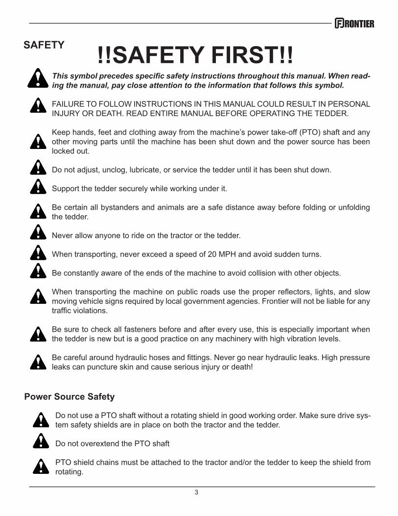
SAFETY !!SAFETY FIRST!!This symbol precedes specific safety instructions throughout this manual. When read-ing the manual, pay close attention to the information that follows this symbol.
FAILURE TO FOLLOW INSTRUCTIONS IN THIS MANUAL COULD RESULT IN PERSONAL INJURY OR DEATH. READ ENTIRE MANUAL BEFORE OPERATING THE TEDDER.
Keep hands, feet and clothing away from the machine’s power take-off (PTO) shaft and any other moving parts until the machine has been shut down and the power source has been locked out.
Do not adjust, unclog, lubricate, or service the tedder until it has been shut down.
Support the tedder securely while working under it.
Be certain all bystanders and animals are a safe distance away before folding or unfolding the tedder.
Never allow anyone to ride on the tractor or the tedder.
When transporting, never exceed a speed of 20 MPH and avoid sudden turns.
Be constantly aware of the ends of the machine to avoid collision with other objects.
When transporting the machine on public roads use the proper reflectors, lights, and slow moving vehicle signs required by local government agencies. Frontier will not be liable for any traffic violations.
Be sure to check all fasteners before and after every use, this is especially important when the tedder is new but is a good practice on any machinery with high vibration levels.
Be careful around hydraulic hoses and fittings. Never go near hydraulic leaks. High pressure leaks can puncture skin and cause serious injury or death!
Power Source Safety
Do not use a PTO shaft without a rotating shield in good working order. Make sure drive sys-tem safety shields are in place on both the tractor and the tedder.
Do not overextend the PTO shaft
PTO shield chains must be attached to the tractor and/or the tedder to keep the shield from rotating.
4
SAFETY
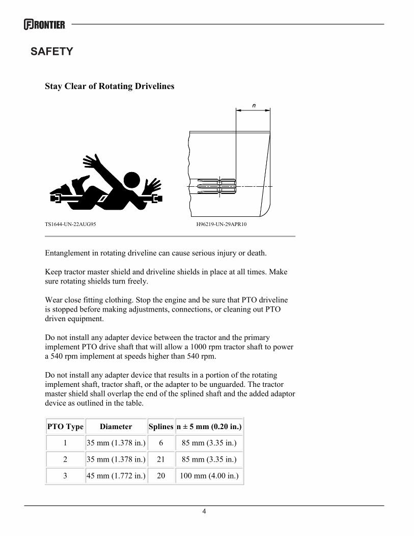
Stay Clear of Rotating Drivelines
TS1644-UN-22AUG95 H96219-UN-29APR10
Entanglement in rotating driveline can cause serious injury or death.
Keep tractor master shield and driveline shields in place at all times. Make sure rotating shields turn freely.
Wear close fitting clothing. Stop the engine and be sure that PTO driveline is stopped before making adjustments, connections, or cleaning out PTO driven equipment.
Do not install any adapter device between the tractor and the primary implement PTO drive shaft that will allow a 1000 rpm tractor shaft to power a 540 rpm implement at speeds higher than 540 rpm.
Do not install any adapter device that results in a portion of the rotating implement shaft, tractor shaft, or the adapter to be unguarded. The tractor master shield shall overlap the end of the splined shaft and the added adaptor device as outlined in the table.
PTO Type Diameter Splines n ± 5 mm (0.20 in.)
1 35 mm (1.378 in.) 6 85 mm (3.35 in.)
2 35 mm (1.378 in.) 21 85 mm (3.35 in.)
3 45 mm (1.772 in.) 20 100 mm (4.00 in.)
5
SAFETY
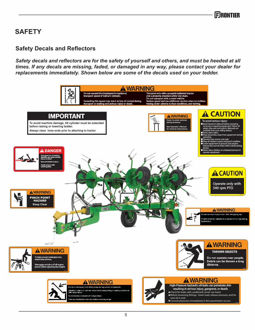
Safety Decals and Reflectors
Safety decals and reflectors are for the safety of yourself and others, and must be heeded at all times. If any decals are missing, faded, or damaged in any way, please contact your dealer for replacements immediately. Shown below are some of the decals used on your tedder.
6
HITCHING
Attaching to the Tractor
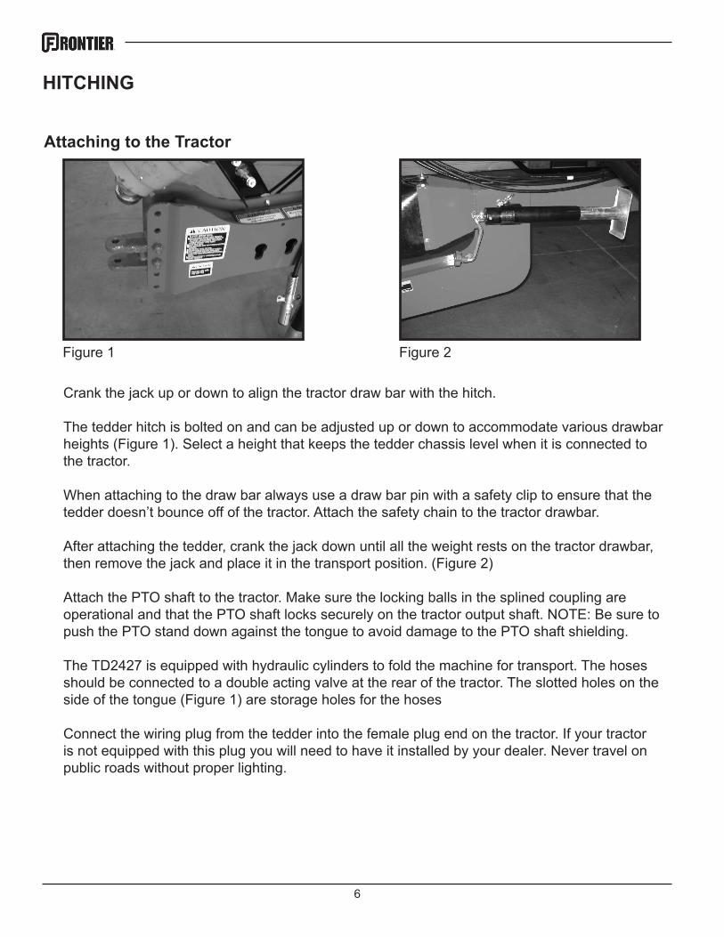
Figure 1
Crank the jack up or down to align the tractor draw bar with the hitch.
The tedder hitch is bolted on and can be adjusted up or down to accommodate various drawbar heights (Figure 1). Select a height that keeps the tedder chassis level when it is connected to the tractor.
When attaching to the draw bar always use a draw bar pin with a safety clip to ensure that the tedder doesn’t bounce off of the tractor. Attach the safety chain to the tractor drawbar.
After attaching the tedder, crank the jack down until all the weight rests on the tractor drawbar, then remove the jack and place it in the transport position. (Figure 2)
Attach the PTO shaft to the tractor. Make sure the locking balls in the splined coupling are operational and that the PTO shaft locks securely on the tractor output shaft. NOTE: Be sure to push the PTO stand down against the tongue to avoid damage to the PTO shaft shielding.
The TD2427 is equipped with hydraulic cylinders to fold the machine for transport. The hoses should be connected to a double acting valve at the rear of the tractor. The slotted holes on the side of the tongue (Figure 1) are storage holes for the hoses
Connect the wiring plug from the tedder into the female plug end on the tractor. If your tractor is not equipped with this plug you will need to have it installed by your dealer. Never travel on public roads without proper lighting.
Figure 2
7
TRANSPORTING
Field Transport
Never allow any riders on the tractor or the tedder.
Remain fully aware of the width of the tedder in relation to objects you are passing.
Never travel at speeds of more than 12 MPH in the field.
Road Transport
Adhere the suggestions for field transport listed above.
ALWAYS FOLLOW LOCAL TRAFFIC LAWS IN REGARDS TO THE TRANSPORTING OF FARM EQUIPMENT. FRONTIER WILL NOT BE HELD LIABLE FOR FINES INCURRED DUE TO TRAFFIC VIOLATIONS.
Do not exceed 20 MPH on any public road. Excessive speeds combined with common road ob-structions can cause failures.
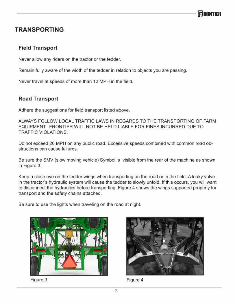
Be sure the SMV (slow moving vehicle) Symbol is visible from the rear of the machine as shown in Figure 3.
Keep a close eye on the tedder wings when transporting on the road or in the field. A leaky valve in the tractor’s hydraulic system will cause the tedder to slowly unfold. If this occurs, you will want to disconnect the hydraulics before transporting. Figure 4 shows the wings supported properly for transport and the safety chains attached.
Be sure to use the lights when traveling on the road at night.
Figure 3 Figure 4
8
FIELD SET UP
To lower the tedder into tedding position engage the hydraulics for the tilt cylinder first to raise the wings off of the chassis then engage the main hydraulics to unfold the wings. Be sure that nobody is around the tedder or the tractor as the wings are lowering. The tines and arms can cause serious injury to anybody that it comes into contact with. Make sure that the hitch is attached to the trac-tor and the pin is installed when the wings are lowering. If the hitch is not properly attached to the tractor the weight of the rotors when it is unfolding could cause the hitch to whip up causing serious personal injury or damage to equipment.
1-2”
NEVER RUN THE PTO WHILE THE TEDDER IS IN THE TRANS-PORT POSITION! THIS CAN CAUSE DAMAGE TO THE JOINTS AND ALSO POSES A PERSONAL INJURY HAZARD.
DO NOT ADJUST THE TEDDER UNLESS THE TRACTOR IS OFF AND THE PTO SHAFT IS DISCONNECTED. ALWAYS ADJUST THE MACHINE BY YOURSELF. A SECOND PERSON INCREASES THE CHANCE OF AN ACCIDENT.
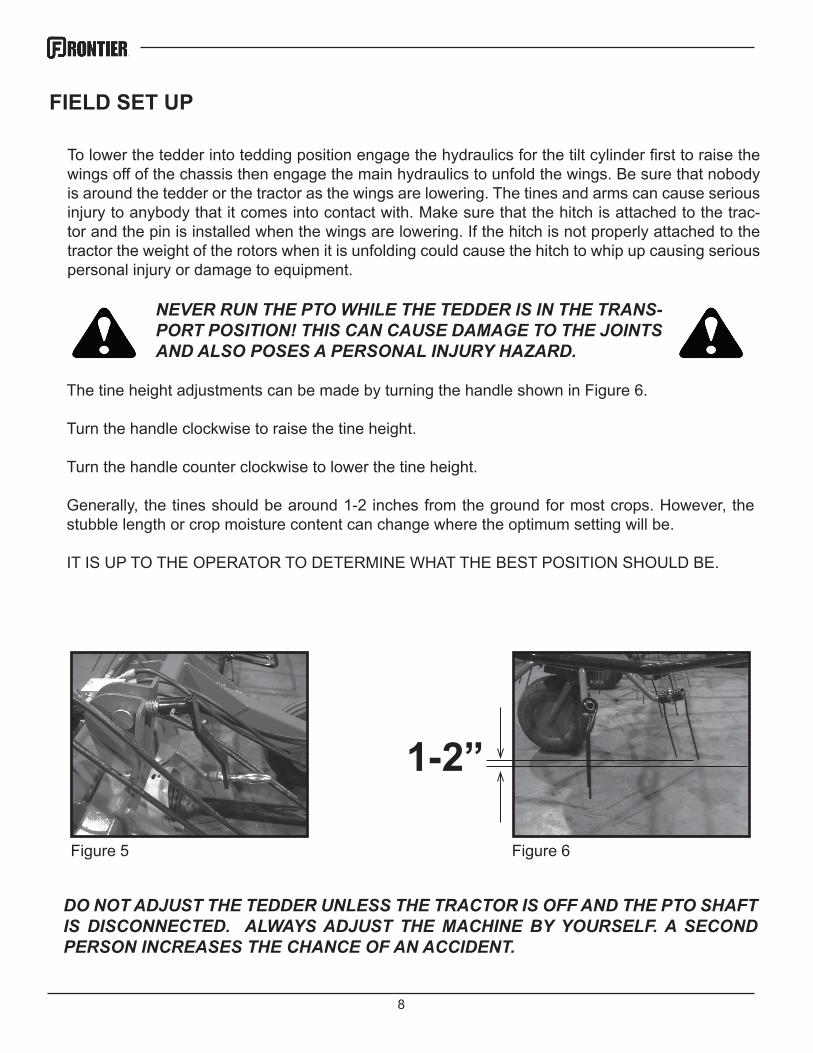
The tine height adjustments can be made by turning the handle shown in Figure 6.
Turn the handle clockwise to raise the tine height.
Turn the handle counter clockwise to lower the tine height.
Generally, the tines should be around 1-2 inches from the ground for most crops. However, the stubble length or crop moisture content can change where the optimum setting will be.
IT IS UP TO THE OPERATOR TO DETERMINE WHAT THE BEST POSITION SHOULD BE.
Figure 5 Figure 6
9
ADJUSTMENTS
Tine Pitch Adjustments
Figure 7 Figure 8
Figure 10Figure 9
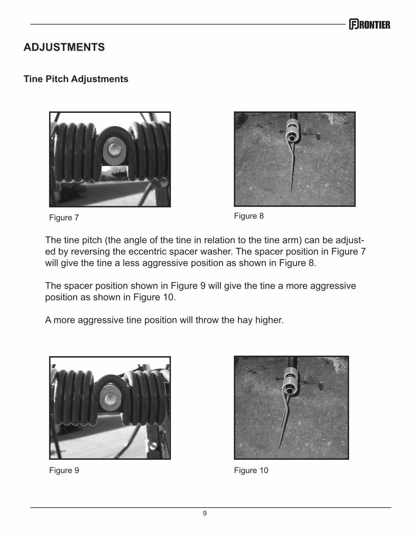
The tine pitch (the angle of the tine in relation to the tine arm) can be adjust-ed by reversing the eccentric spacer washer. The spacer position in Figure 7 will give the tine a less aggressive position as shown in Figure 8.
The spacer position shown in Figure 9 will give the tine a more aggressive position as shown in Figure 10.
A more aggressive tine position will throw the hay higher.
10
ADJUSTMENTS
Axle Adjustments
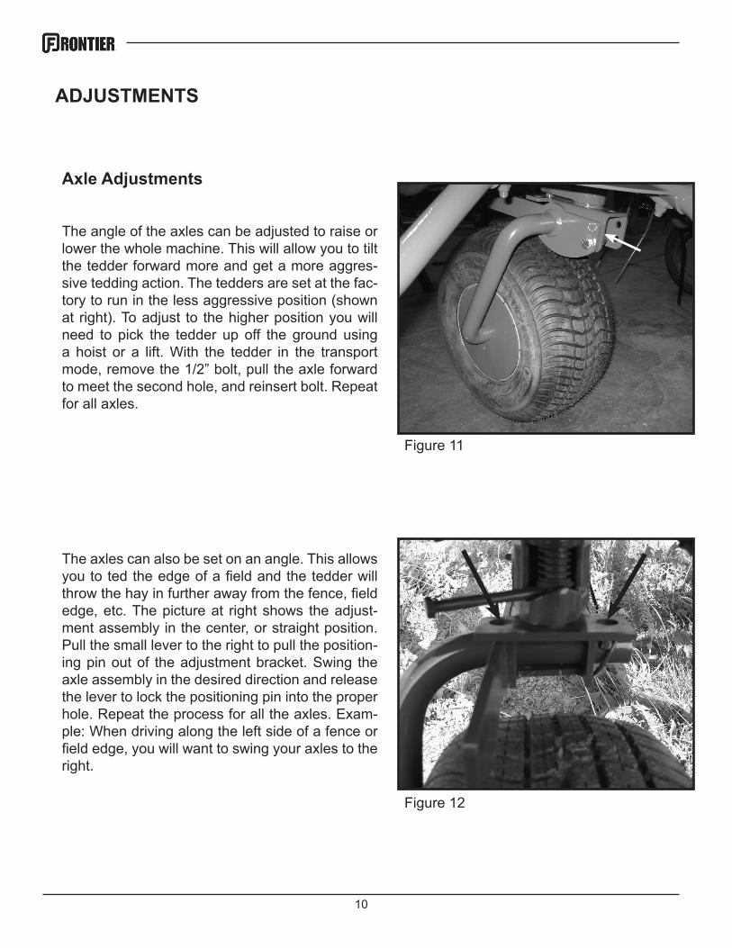
The angle of the axles can be adjusted to raise or lower the whole machine. This will allow you to tilt the tedder forward more and get a more aggres-sive tedding action. The tedders are set at the fac-tory to run in the less aggressive position (shown at right). To adjust to the higher position you will need to pick the tedder up off the ground using a hoist or a lift. With the tedder in the transport mode, remove the 1/2” bolt, pull the axle forward to meet the second hole, and reinsert bolt. Repeat for all axles.
The axles can also be set on an angle. This allows you to ted the edge of a field and the tedder will throw the hay in further away from the fence, field edge, etc. The picture at right shows the adjust-ment assembly in the center, or straight position. Pull the small lever to the right to pull the position-ing pin out of the adjustment bracket. Swing the axle assembly in the desired direction and release the lever to lock the positioning pin into the proper hole. Repeat the process for all the axles. Exam-ple: When driving along the left side of a fence or field edge, you will want to swing your axles to the right.
Figure 11
Figure 12
11
DO NOT BEGIN OPERATION UNTIL ALL OF THE SAFETY WARNINGS HAVE BEEN READ AND UNDERSTOOD!
Once all of the adjustments and initial set up instructions have been followed and the proper adjustments made, the tedder is ready to operate in the field.
Connect the tedder PTO shaft to the tractor by pulling the spring collar back and sliding the shaft yoke onto the 6 splined tractor PTO shaft. Slide the shaft forward until it stops and then pull back slowly until the balls engage into the ball groove on the tractor shaft.
DO NOT RUN THE PTO UNLESS THE LOCKING BALLS ARE ENGAGED. THE SHAFT COULD SLIDE OFF DURING OPERATION AND CAUSE SERIOUS INJURY OR DEATH.
The PTO speed should never exceed 540 rpm. Generally, 450 rpm and a 6 mph ground speed is a comfortable operating setting. Crop conditions and field conditions will ultimately determine the settings for the tedder and the tractor.
GENERAL OPERATION
Folding for Transport
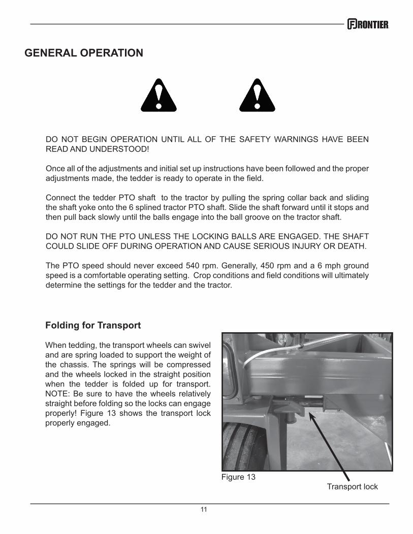
When tedding, the transport wheels can swivel and are spring loaded to support the weight of the chassis. The springs will be compressed and the wheels locked in the straight position when the tedder is folded up for transport. NOTE: Be sure to have the wheels relatively straight before folding so the locks can engage properly! Figure 13 shows the transport lock properly engaged.
Transport lockFigure 13
12
LUBRICATION AND MAINTENANCE
NEVER PERFORM ROUTINE MAINTENANCE, REPAIRS OR INSPECTIONS ON ANY PIECE OF EQUIPMENT UNLESS THE TRACTOR IS SHUT OFF AND DISCONNECTED FROM THE MACHINE.
IT IS ALWAYS BETTER TO WORK WITH ANOTHER PERSON WHEN MAINTAINING OR SERVICING A PIECE OF EQUIPMENT. ACCIDENTS CAN BE PREVENTED AND HELP CAN BE ATTAINED EASIER WHEN ANOTHER PERSON IS AVAILABLE TO HELP.
Gearbox Lubrication
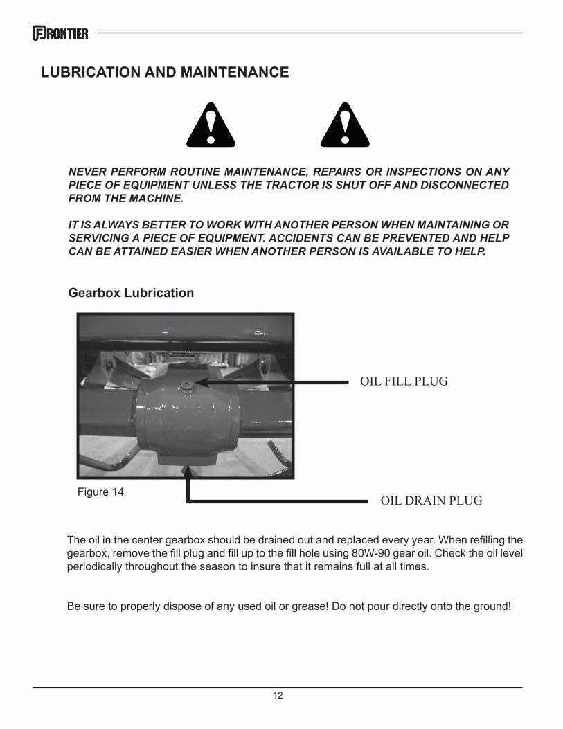
The oil in the center gearbox should be drained out and replaced every year. When refilling the gearbox, remove the fill plug and fill up to the fill hole using 80W-90 gear oil. Check the oil level periodically throughout the season to insure that it remains full at all times.
Be sure to properly dispose of any used oil or grease! Do not pour directly onto the ground!
Figure 14
OIL FILL PLUG
OIL DRAIN PLUG
13
LUBRICATION AND MAINTENANCE
Figure 15
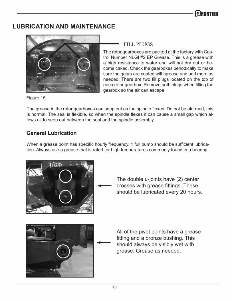
FILL PLUGSThe rotor gearboxes are packed at the factory with Cas-trol Number NLGI #2 EP Grease. This is a grease with a high resistance to water and will not dry out or be-come caked. Check the gearboxes periodically to make sure the gears are coated with grease and add more as needed. There are two fill plugs located on the top of each rotor gearbox. Remove both plugs when filling the gearbox so the air can escape.
The double u-joints have (2) center crosses with grease fittings. These should be lubricated every 20 hours.
All of the pivot points have a grease fitting and a bronze bushing. This should always be visibly wet with grease. Grease as needed.
General Lubrication
When a grease point has specific hourly frequency, 1 full pump should be sufficient lubrica-tion. Always use a grease that is rated for high temperatures commonly found in a bearing.
The grease in the rotor gearboxes can seep out as the spindle flexes. Do not be alarmed, this is normal. The seal is flexible, so when the spindle flexes it can cause a small gap which al-lows oil to seep out between the seal and the spindle assembly.

14
The cylinder nut should always be visually wet with grease. Grease as needed.
LUBRICATION AND MAINTENANCE
The wheel bearings are sealed bear-ings and should be greased periodi-cally but can be overgreased. Once per season should be adequate.
The transport lock slide should be greased regularly and should be kept visibly wet with grease. The sliding shaft should be cleaned periodically to prevent buildup that would prevent it from sliding smoothly.
15
LUBRICATION AND MAINTENANCE
As is the case with any piece of new equipment, periodically check for loose bolts and nuts. Paint and parts settling after the initial vibrations are common and can cause bolts or nuts to loosen. Check the following parts frequently:
• Lug Bolts• Tines & Tine Arms• Guards• Hydraulic Fittings• All Fasteners
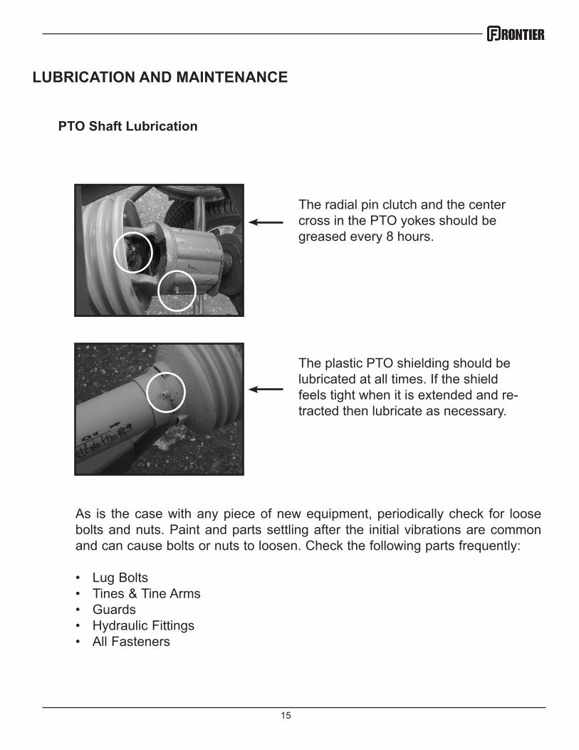
The plastic PTO shielding should be lubricated at all times. If the shield feels tight when it is extended and re-tracted then lubricate as necessary.
The radial pin clutch and the center cross in the PTO yokes should be greased every 8 hours.
PTO Shaft Lubrication
16
Wheel Bearings
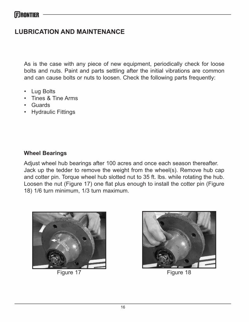
Adjust wheel hub bearings after 100 acres and once each season thereafter.Jack up the tedder to remove the weight from the wheel(s). Remove hub cap and cotter pin. Torque wheel hub slotted nut to 35 ft. lbs. while rotating the hub. Loosen the nut (Figure 17) one flat plus enough to install the cotter pin (Figure 18) 1/6 turn minimum, 1/3 turn maximum.
Figure 18
LUBRICATION AND MAINTENANCE
As is the case with any piece of new equipment, periodically check for loose bolts and nuts. Paint and parts settling after the initial vibrations are common and can cause bolts or nuts to loosen. Check the following parts frequently:
• Lug Bolts• Tines & Tine Arms• Guards• Hydraulic Fittings
Figure 17
Loosen
17
ELECTRICAL
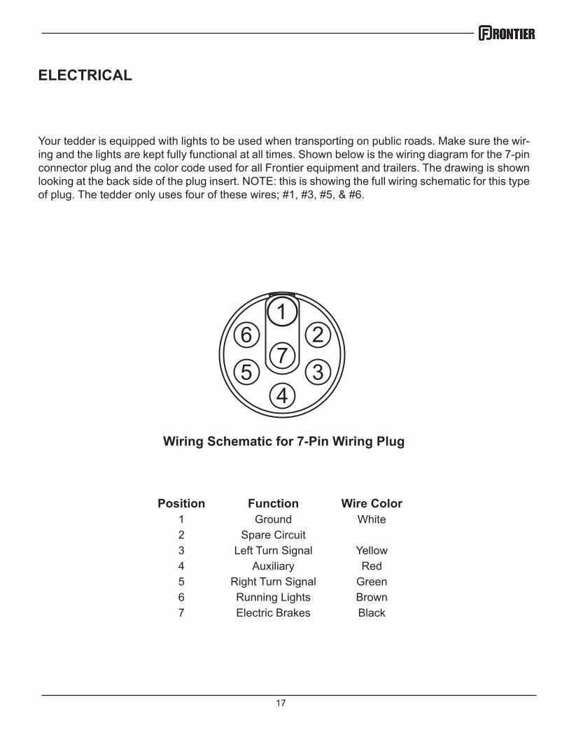
Your tedder is equipped with lights to be used when transporting on public roads. Make sure the wir-ing and the lights are kept fully functional at all times. Shown below is the wiring diagram for the 7-pin connector plug and the color code used for all Frontier equipment and trailers. The drawing is shown looking at the back side of the plug insert. NOTE: this is showing the full wiring schematic for this type of plug. The tedder only uses four of these wires; #1, #3, #5, & #6.
12
34
76
5
Position Function Wire Color1 Ground White2 Spare Circuit3 Left Turn Signal Yellow4 Auxiliary Red5 Right Turn Signal Green6 Running Lights Brown7 Electric Brakes Black
Wiring Schematic for 7-Pin Wiring Plug
18
TECHNICAL
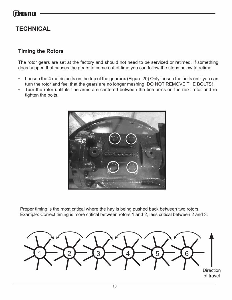
Timing the Rotors
The rotor gears are set at the factory and should not need to be serviced or retimed. If something does happen that causes the gears to come out of time you can follow the steps below to retime:
• Loosen the 4 metric bolts on the top of the gearbox (Figure 20) Only loosen the bolts until you can turn the rotor and feel that the gears are no longer meshing. DO NOT REMOVE THE BOLTS!
• Turn the rotor until its tine arms are centered between the tine arms on the next rotor and re-tighten the bolts.
Proper timing is the most critical where the hay is being pushed back between two rotors. Example: Correct timing is more critical between rotors 1 and 2, less critical between 2 and 3.
1 2 3 4 5 6
Direction of travel
19
TECHNICAL
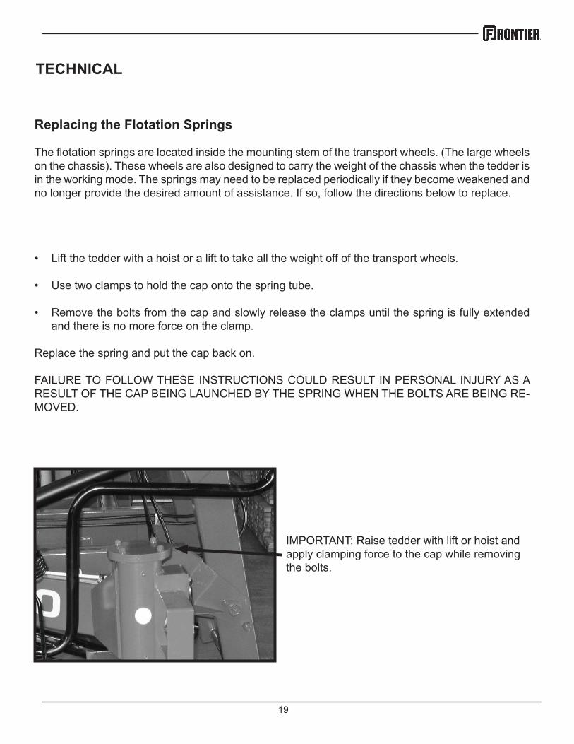
Replacing the Flotation Springs
The flotation springs are located inside the mounting stem of the transport wheels. (The large wheels on the chassis). These wheels are also designed to carry the weight of the chassis when the tedder is in the working mode. The springs may need to be replaced periodically if they become weakened and no longer provide the desired amount of assistance. If so, follow the directions below to replace.
• Lift the tedder with a hoist or a lift to take all the weight off of the transport wheels.
• Use two clamps to hold the cap onto the spring tube.
• Remove the bolts from the cap and slowly release the clamps until the spring is fully extended and there is no more force on the clamp.
Replace the spring and put the cap back on.
FAILURE TO FOLLOW THESE INSTRUCTIONS COULD RESULT IN PERSONAL INJURY AS A RESULT OF THE CAP BEING LAUNCHED BY THE SPRING WHEN THE BOLTS ARE BEING RE-MOVED.
IMPORTANT: Raise tedder with lift or hoist and apply clamping force to the cap while removing the bolts.
20
TORQUE SPECIFICATIONS
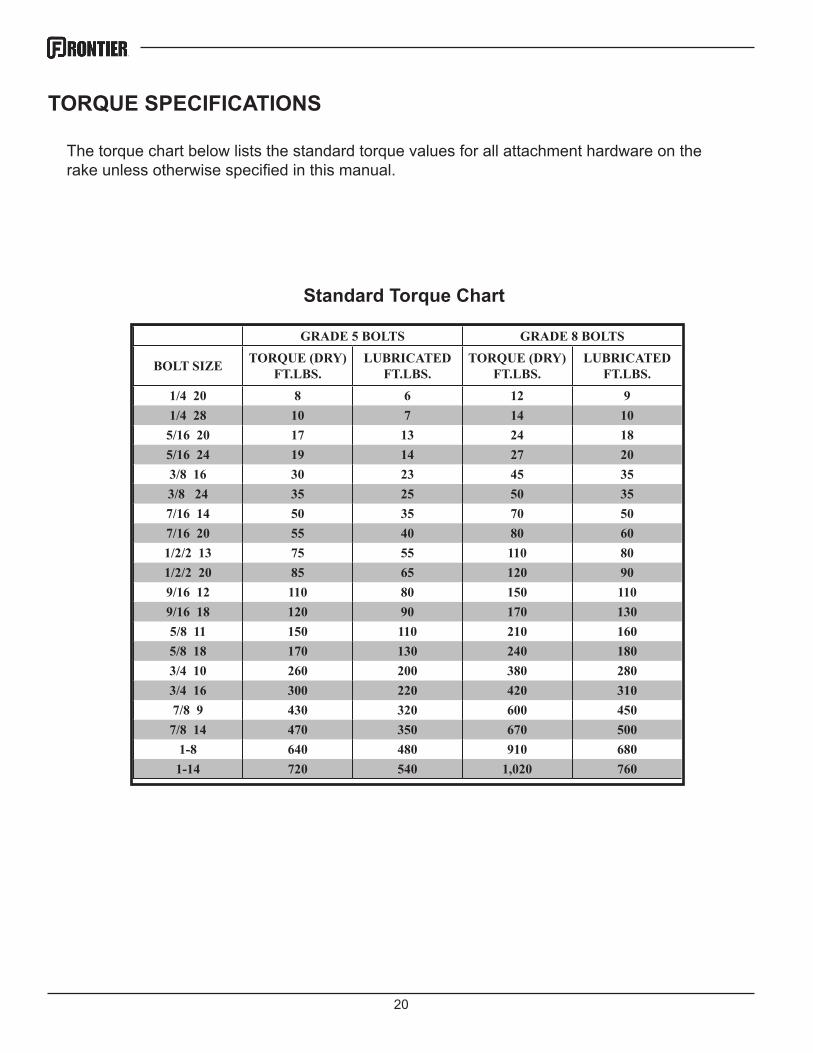
GRADE 5 BOLTS GRADE 8 BOLTS
BOLT SIZE TORQUE (DRY) FT.LBS.
LUBRICATED FT.LBS.
TORQUE (DRY) FT.LBS.
LUBRICATED FT.LBS.
1/4 20 8 6 12 91/4 28 10 7 14 105/16 20 17 13 24 185/16 24 19 14 27 203/8 16 30 23 45 353/8 24 35 25 50 357/16 14 50 35 70 507/16 20 55 40 80 601/2/2 13 75 55 110 801/2/2 20 85 65 120 909/16 12 110 80 150 1109/16 18 120 90 170 1305/8 11 150 110 210 1605/8 18 170 130 240 1803/4 10 260 200 380 2803/4 16 300 220 420 3107/8 9 430 320 600 4507/8 14 470 350 670 500
1-8 640 480 910 6801-14 720 540 1,020 760
Standard Torque Chart
The torque chart below lists the standard torque values for all attachment hardware on the rake unless otherwise specified in this manual.
21
TORQUE SPECIFICATIONS
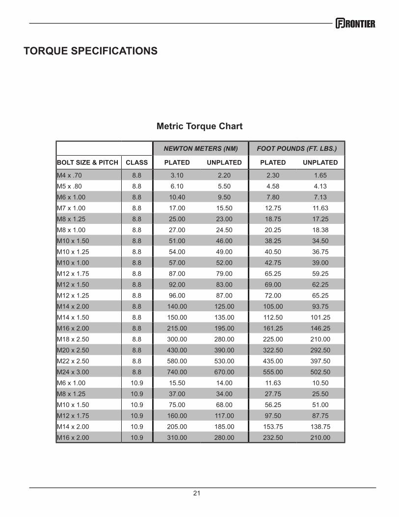
NEWTON METERS (NM) FOOT POUNDS (FT. LBS.)
BOLT SIZE & PITCH CLASS PLATED UNPLATED PLATED UNPLATED
M4 x .70 8.8 3.10 2.20 2.30 1.65
M5 x .80 8.8 6.10 5.50 4.58 4.13
M6 x 1.00 8.8 10.40 9.50 7.80 7.13
M7 x 1.00 8.8 17.00 15.50 12.75 11.63
M8 x 1.25 8.8 25.00 23.00 18.75 17.25
M8 x 1.00 8.8 27.00 24.50 20.25 18.38
M10 x 1.50 8.8 51.00 46.00 38.25 34.50
M10 x 1.25 8.8 54.00 49.00 40.50 36.75
M10 x 1.00 8.8 57.00 52.00 42.75 39.00
M12 x 1.75 8.8 87.00 79.00 65.25 59.25
M12 x 1.50 8.8 92.00 83.00 69.00 62.25
M12 x 1.25 8.8 96.00 87.00 72.00 65.25
M14 x 2.00 8.8 140.00 125.00 105.00 93.75
M14 x 1.50 8.8 150.00 135.00 112.50 101.25
M16 x 2.00 8.8 215.00 195.00 161.25 146.25
M18 x 2.50 8.8 300.00 280.00 225.00 210.00
M20 x 2.50 8.8 430.00 390.00 322.50 292.50
M22 x 2.50 8.8 580.00 530.00 435.00 397.50
M24 x 3.00 8.8 740.00 670.00 555.00 502.50
M6 x 1.00 10.9 15.50 14.00 11.63 10.50
M8 x 1.25 10.9 37.00 34.00 27.75 25.50
M10 x 1.50 10.9 75.00 68.00 56.25 51.00
M12 x 1.75 10.9 160.00 117.00 97.50 87.75
M14 x 2.00 10.9 205.00 185.00 153.75 138.75
M16 x 2.00 10.9 310.00 280.00 232.50 210.00
Metric Torque Chart
22
WARRANTY
Warranty coverage is provided by John Deere according to the terms of the Agricultural/Commercial & Consumer Equipment Warranty Statement. Carefully read the warranty statement on the back of your original purchase order for details on coverage and limitations of this warranty.

23
Illustrated Parts
Breakdowns
24
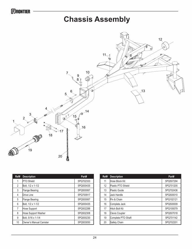
Chassis Assembly
12
3
4
56
7
89
10
11
13
12
1415
1617
18
19
20
Ref# Description Part# Ref# Description Part# 1 PTO Shield 5PQ702333 11 Hose Block Kit 5PQ5072942 Bolt, 1/2 x 1-1/2 5PQ000435 12 Plastic PTO Shield 5PQ7012053 Flange Bearing 5PQ500067 13 Plastic Guide 5PQ7024364 Drive Line 5PQ700917 14 Jack Handle 5PQ5000105 Flange Bearing 5PQ500067 15 Pin & Chain 5PQ1021216 Bolt, 1/2 x 1-1/2 5PQ000435 16 Complete Jack 5PQ5000097 Hose Support 5PQ502288 17 Hitch Bolt Kit 5PQ1000798 Hose Support Washer 5PQ502308 18 Clevis Coupler 5PQ5070189 Bolt, 5/16 x 1-1/4 5PQ000230 19 Complete PTO Shaft 5PQ701142
10 Owner’s Manual Canister 5PQ503050 20 Safety Chain 5PQ702201
25
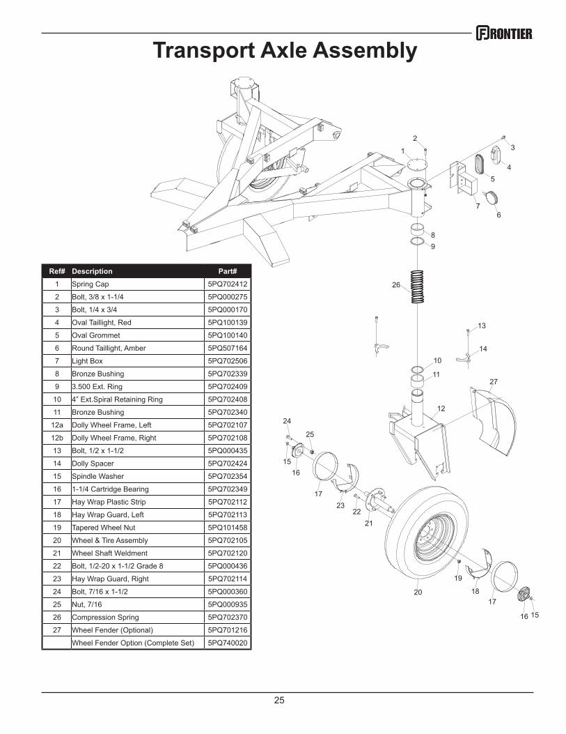
Transport Axle Assembly
1
23
45
67
89
10
11
12
13
14
16
19
20
2122
1615
17
1817
15
23
24
25
27
26
Ref# Description Part# 1 Spring Cap 5PQ702412
2 Bolt, 3/8 x 1-1/4 5PQ000275
3 Bolt, 1/4 x 3/4 5PQ000170
4 Oval Taillight, Red 5PQ100139
5 Oval Grommet 5PQ100140
6 Round Taillight, Amber 5PQ507164
7 Light Box 5PQ702506
8 Bronze Bushing 5PQ702339
9 3.500 Ext. Ring 5PQ702409
10 4” Ext.Spiral Retaining Ring 5PQ702408
11 Bronze Bushing 5PQ702340
12a Dolly Wheel Frame, Left 5PQ702107
12b Dolly Wheel Frame, Right 5PQ702108
13 Bolt, 1/2 x 1-1/2 5PQ000435
14 Dolly Spacer 5PQ702424
15 Spindle Washer 5PQ702354
16 1-1/4 Cartridge Bearing 5PQ702349
17 Hay Wrap Plastic Strip 5PQ702112
18 Hay Wrap Guard, Left 5PQ702113
19 Tapered Wheel Nut 5PQ101458
20 Wheel & Tire Assembly 5PQ702105
21 Wheel Shaft Weldment 5PQ702120
22 Bolt, 1/2-20 x 1-1/2 Grade 8 5PQ000436
23 Hay Wrap Guard, Right 5PQ702114
24 Bolt, 7/16 x 1-1/2 5PQ000360
25 Nut, 7/16 5PQ000935
26 Compression Spring 5PQ702370
27 Wheel Fender (Optional) 5PQ701216
Wheel Fender Option (Complete Set) 5PQ740020
26
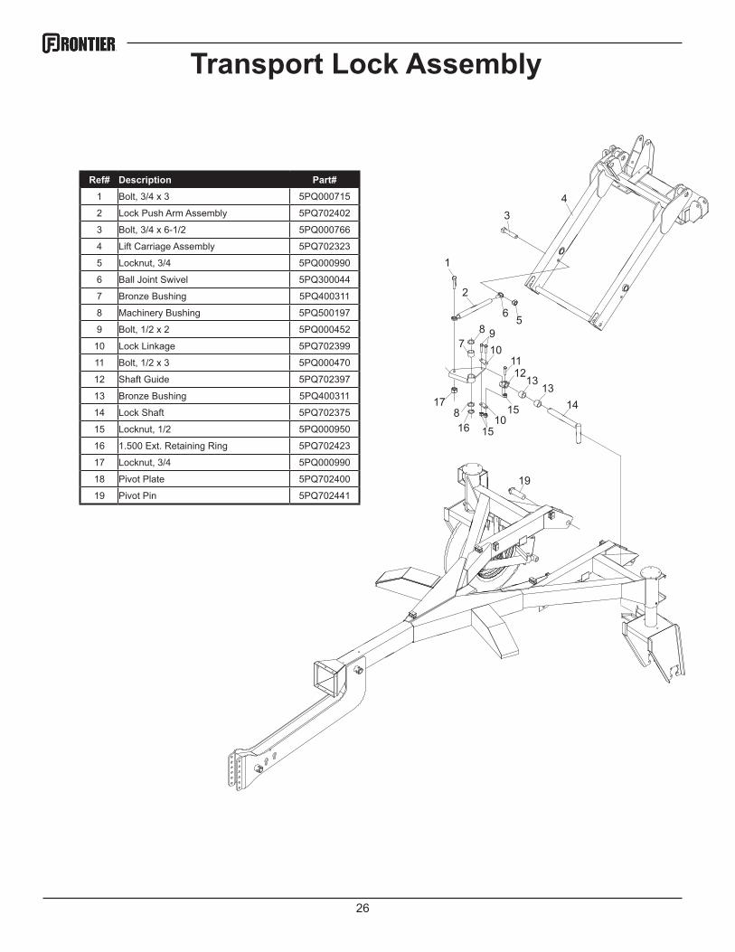
Transport Lock Assembly
1
2
34
56
87
910
1112
1313
141510
1516 8
17
19
Ref# Description Part# 1 Bolt, 3/4 x 3 5PQ000715
2 Lock Push Arm Assembly 5PQ702402
3 Bolt, 3/4 x 6-1/2 5PQ000766
4 Lift Carriage Assembly 5PQ702323
5 Locknut, 3/4 5PQ000990
6 Ball Joint Swivel 5PQ300044
7 Bronze Bushing 5PQ400311
8 Machinery Bushing 5PQ500197
9 Bolt, 1/2 x 2 5PQ000452
10 Lock Linkage 5PQ702399
11 Bolt, 1/2 x 3 5PQ000470
12 Shaft Guide 5PQ702397
13 Bronze Bushing 5PQ400311
14 Lock Shaft 5PQ702375
15 Locknut, 1/2 5PQ000950
16 1.500 Ext. Retaining Ring 5PQ702423
17 Locknut, 3/4 5PQ000990
18 Pivot Plate 5PQ702400
19 Pivot Pin 5PQ702441
27
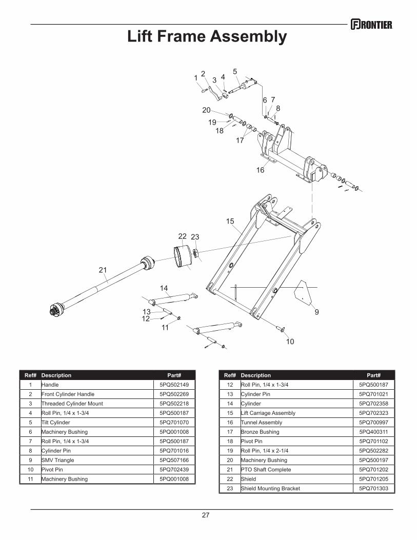
Lift Frame Assembly
1 23 4
5
6 78
9
10
111213
14
15
16
1718
19
21
22 23
20
Ref# Description Part# Ref# Description Part# 1 Handle 5PQ502149 12 Roll Pin, 1/4 x 1-3/4 5PQ500187
2 Front Cylinder Handle 5PQ502269 13 Cylinder Pin 5PQ701021
3 Threaded Cylinder Mount 5PQ502218 14 Cylinder 5PQ702358
4 Roll Pin, 1/4 x 1-3/4 5PQ500187 15 Lift Carriage Assembly 5PQ702323
5 Tilt Cylinder 5PQ701070 16 Tunnel Assembly 5PQ700997
6 Machinery Bushing 5PQ001008 17 Bronze Bushing 5PQ400311
7 Roll Pin, 1/4 x 1-3/4 5PQ500187 18 Pivot Pin 5PQ701102
8 Cylinder Pin 5PQ701016 19 Roll Pin, 1/4 x 2-1/4 5PQ502282
9 SMV Triangle 5PQ507166 20 Machinery Bushing 5PQ500197
10 Pivot Pin 5PQ702439 21 PTO Shaft Complete 5PQ701202
11 Machinery Bushing 5PQ001008 22 Shield 5PQ701205
23 Shield Mounting Bracket 5PQ701303
28
1
3
4
4
9
10
11
12
5
5
6
6
7
8
2
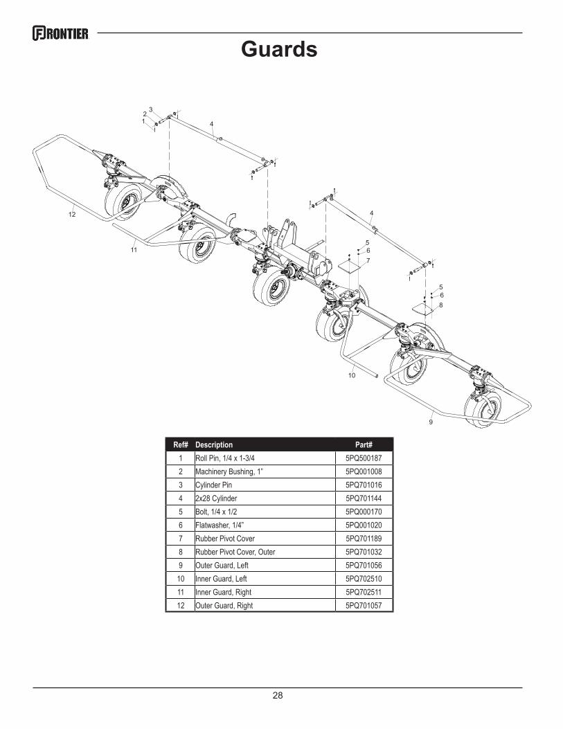
Guards
Ref# Description Part# 1 Roll Pin, 1/4 x 1-3/4 5PQ5001872 Machinery Bushing, 1” 5PQ0010083 Cylinder Pin 5PQ7010164 2x28 Cylinder 5PQ7011445 Bolt, 1/4 x 1/2 5PQ0001706 Flatwasher, 1/4” 5PQ0010207 Rubber Pivot Cover 5PQ7011898 Rubber Pivot Cover, Outer 5PQ7010329 Outer Guard, Left 5PQ701056
10 Inner Guard, Left 5PQ70251011 Inner Guard, Right 5PQ70251112 Outer Guard, Right 5PQ701057
29
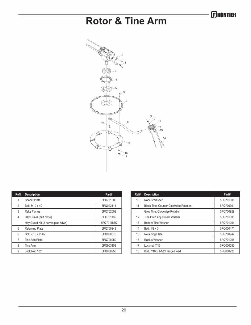
Rotor & Tine Arm
1
2
3
4
6
7
8
910
12
14
16
15
17
18 11
13
5
Ref# Description Part# Ref# Description Part# 1 Spacer Plate 5PQ701006 10 Radius Washer 5PQ7010082 Bolt, M10 x 40 5PQ002415 11 Black Tine, Counter Clockwise Rotation 5PQ7009013 Rake Flange 5PQ702002 Grey Tine, Clockwise Rotation 5PQ7009294 Hay Guard (half circle) 5PQ701185 12 Tine Pitch Adjustment Washer 5PQ701005
Hay Guard Kit (2 halves plus hdwr.) 5PQ701185K 13 Bottom Tine Washer 5PQ7010045 Retaining Plate 5PQ700943 14 Bolt, 1/2 x 3 5PQ0004716 Bolt, 7/16 x 2-1/2 5PQ000375 15 Retaining Plate 5PQ7009427 Tine Arm Plate 5PQ700950 16 Radius Washer 5PQ7010088 Tine Arm 5PQ903153 17 Locknut, 7/16 5PQ0003859 Lock Nut, 1/2” 5PQ000950 18 Bolt, 7/16 x 1-1/2 Flange Head 5PQ000725
30
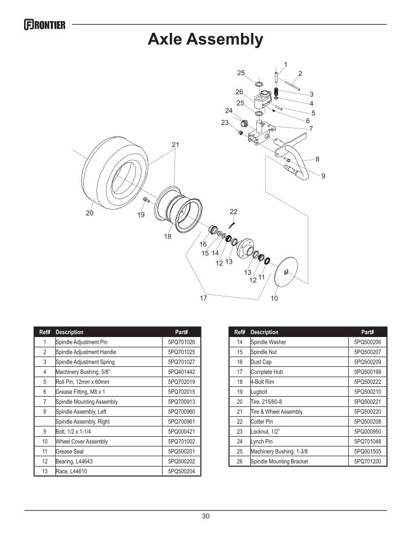
Axle Assembly1
2
345
67
8
9
10
111213
13121415
16
17
18
1920 22
21
23
242526
25
Ref# Description Part# Ref# Description Part# 1 Spindle Adjustment Pin 5PQ701026 14 Spindle Washer 5PQ5002062 Spindle Adjustment Handle 5PQ701025 15 Spindle Nut 5PQ5002073 Spindle Adjustment Spring 5PQ701027 16 Dust Cap 5PQ5002094 Machinery Bushing, 5/8” 5PQ401442 17 Complete Hub 5PQ5001995 Roll Pin, 12mm x 60mm 5PQ702019 18 4-Bolt Rim 5PQ5002226 Grease Fitting, M8 x 1 5PQ702015 19 Lugbolt 5PQ5002107 Spindle Mounting Assembly 5PQ700913 20 Tire, 215/60-8 5PQ5002218 Spindle Assembly, Left 5PQ700960 21 Tire & Wheel Assembly 5PQ500220
Spindle Assembly, Right 5PQ700961 22 Cotter Pin 5PQ5002089 Bolt, 1/2 x 1-1/4 5PQ000421 23 Locknut, 1/2” 5PQ000950
10 Wheel Cover Assembly 5PQ701002 24 Lynch Pin 5PQ70104811 Grease Seal 5PQ500201 25 Machinery Bushing, 1-3/8 5PQ00150512 Bearing, L44643 5PQ500202 26 Spindle Mounting Bracket 5PQ70120013 Race, L44610 5PQ500204
31
1
2
3
19
8
8
9
10
1112 13
1412
15
16
111213
1412
17
21
20
22
23
22
24
25
18
4
4
4
5
5
65
5
4 7
7
See page 32 for exploded breakdown
of gearbox
See page 33 for exploded breakdown
of gearbox
See page 34 for exploded breakdown
of gearbox
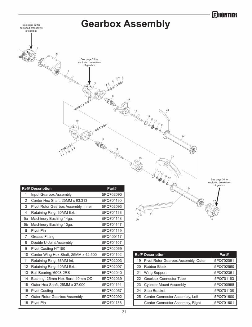
Gearbox Assembly
Ref# Description Part# 1 Input Gearbox Assembly 5PQ7020902 Center Hex Shaft, 25MM x 63.313 5PQ7011903 Pivot Rotor Gearbox Assembly, Inner 5PQ7020934 Retaining Ring, 30MM Ext. 5PQ701138
5a Machinery Bushing 14ga. 5PQ7011485b Machinery Bushing 10ga. 5PQ7011476 Pivot Pin 5PQ7011397 Grease Fitting 5PQ4001178 Double U-Joint Assembly 5PQ7011079 Pivot Casting HT150 5PQ702069
10 Center Wing Hex Shaft, 25MM x 42.500 5PQ701192 Ref# Description Part# 11 Retaining Ring, 68MM Int. 5PQ702003 19 Pivot Rotor Gearbox Assembly, Outer 5PQ70209112 Retaining Ring, 40MM Ext. 5PQ702007 20 Rubber Block 5PQ70256013 Ball Bearing, 6008-2RS 5PQ702040 21 Wing Support 5PQ70236114 Bushing, 25mm Hex Bore, 40mm OD 5PQ702039 22 Gearbox Connector Tube 5PQ70116315 Outer Hex Shaft, 25MM x 37.000 5PQ701191 23 Cylinder Mount Assembly 5PQ70099816 Pivot Casting 5PQ702057 24 Stop Bracket 5PQ70110817 Outer Rotor Gearbox Assembly 5PQ702092 25 Center Connecter Assembly, Left 5PQ70160018 Pivot Pin 5PQ701188 Center Connecter Assembly, Right 5PQ701601
32
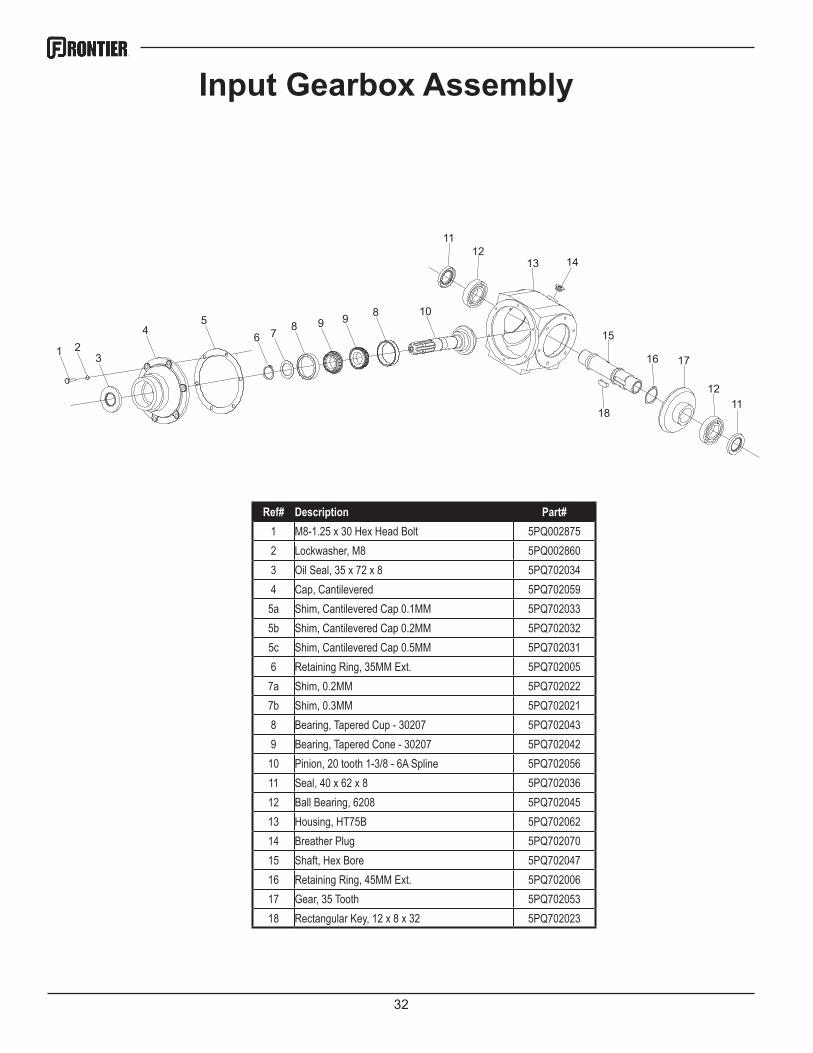
Input Gearbox Assembly
321
45
6 7 8 9 9 8 10
1112
13
15
14
16 17
1211
18
Ref# Description Part# 1 M8-1.25 x 30 Hex Head Bolt 5PQ0028752 Lockwasher, M8 5PQ0028603 Oil Seal, 35 x 72 x 8 5PQ7020344 Cap, Cantilevered 5PQ702059
5a Shim, Cantilevered Cap 0.1MM 5PQ7020335b Shim, Cantilevered Cap 0.2MM 5PQ7020325c Shim, Cantilevered Cap 0.5MM 5PQ7020316 Retaining Ring, 35MM Ext. 5PQ702005
7a Shim, 0.2MM 5PQ7020227b Shim, 0.3MM 5PQ7020218 Bearing, Tapered Cup - 30207 5PQ7020439 Bearing, Tapered Cone - 30207 5PQ702042
10 Pinion, 20 tooth 1-3/8 - 6A Spline 5PQ70205611 Seal, 40 x 62 x 8 5PQ70203612 Ball Bearing, 6208 5PQ70204513 Housing, HT75B 5PQ70206214 Breather Plug 5PQ70207015 Shaft, Hex Bore 5PQ70204716 Retaining Ring, 45MM Ext. 5PQ70200617 Gear, 35 Tooth 5PQ70205318 Rectangular Key, 12 x 8 x 32 5PQ702023
33
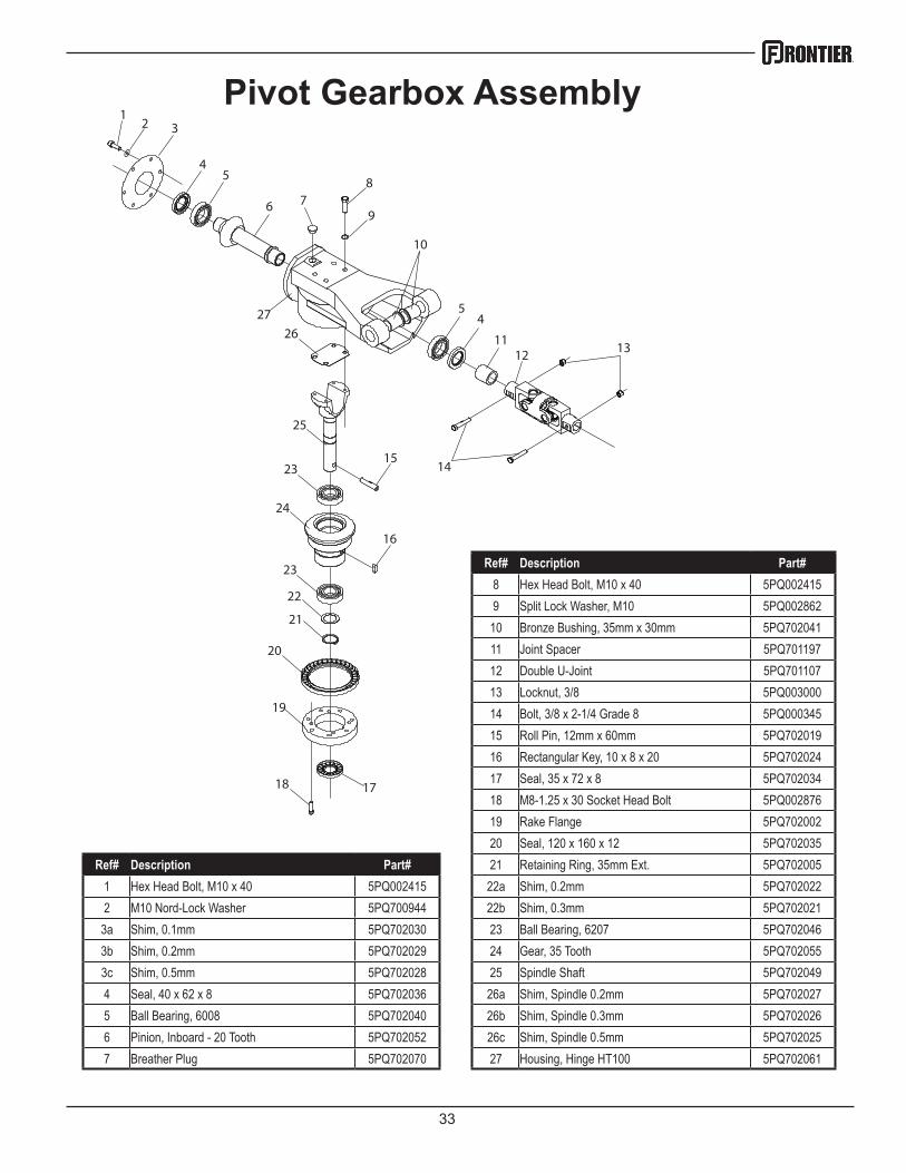
Pivot Gearbox Assembly1
32
45
6 78
9
10
11
54
1213
1415
16
1718
19
20
21
22
23
24
23
25
27
26
Ref# Description Part# 8 Hex Head Bolt, M10 x 40 5PQ0024159 Split Lock Washer, M10 5PQ002862
10 Bronze Bushing, 35mm x 30mm 5PQ70204111 Joint Spacer 5PQ70119712 Double U-Joint 5PQ70110713 Locknut, 3/8 5PQ00300014 Bolt, 3/8 x 2-1/4 Grade 8 5PQ00034515 Roll Pin, 12mm x 60mm 5PQ70201916 Rectangular Key, 10 x 8 x 20 5PQ70202417 Seal, 35 x 72 x 8 5PQ70203418 M8-1.25 x 30 Socket Head Bolt 5PQ00287619 Rake Flange 5PQ70200220 Seal, 120 x 160 x 12 5PQ702035
Ref# Description Part# 21 Retaining Ring, 35mm Ext. 5PQ7020051 Hex Head Bolt, M10 x 40 5PQ002415 22a Shim, 0.2mm 5PQ7020222 M10 Nord-Lock Washer 5PQ700944 22b Shim, 0.3mm 5PQ702021
3a Shim, 0.1mm 5PQ702030 23 Ball Bearing, 6207 5PQ7020463b Shim, 0.2mm 5PQ702029 24 Gear, 35 Tooth 5PQ7020553c Shim, 0.5mm 5PQ702028 25 Spindle Shaft 5PQ7020494 Seal, 40 x 62 x 8 5PQ702036 26a Shim, Spindle 0.2mm 5PQ7020275 Ball Bearing, 6008 5PQ702040 26b Shim, Spindle 0.3mm 5PQ7020266 Pinion, Inboard - 20 Tooth 5PQ702052 26c Shim, Spindle 0.5mm 5PQ7020257 Breather Plug 5PQ702070 27 Housing, Hinge HT100 5PQ702061
34
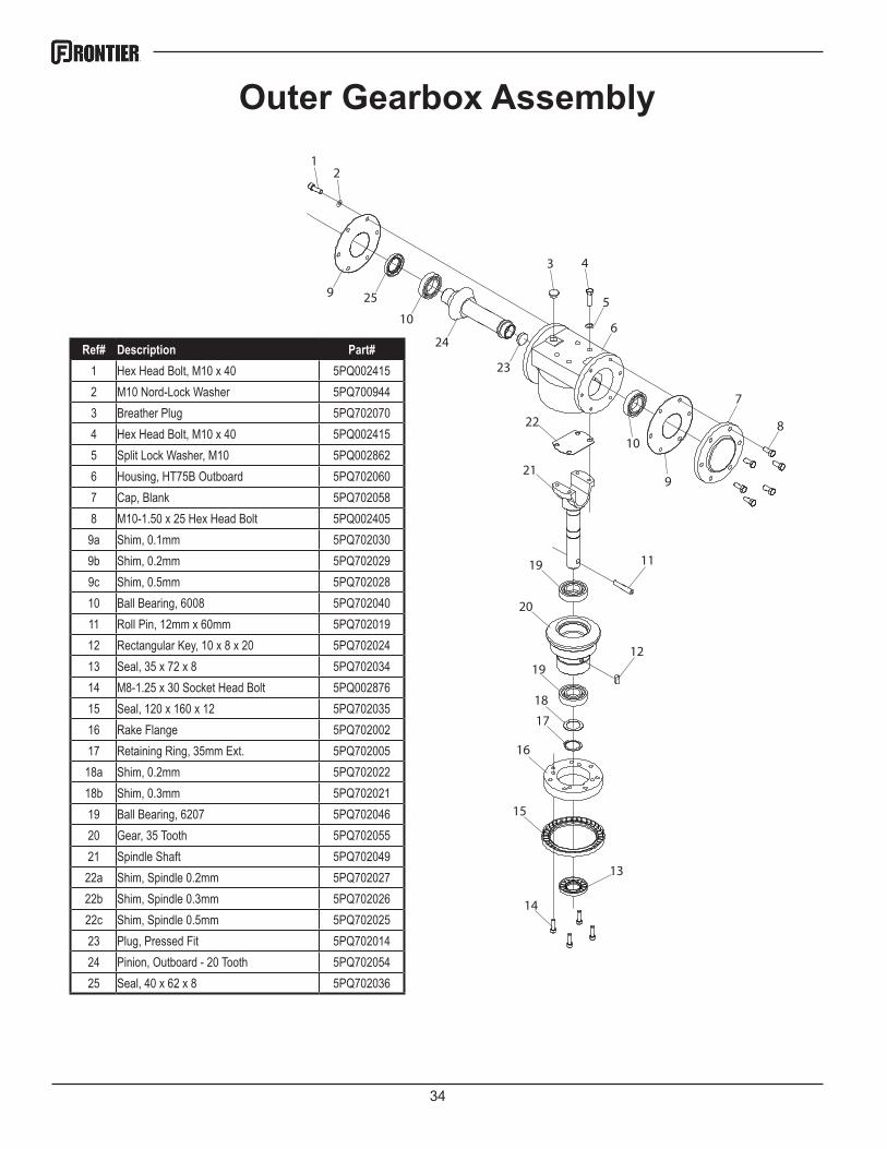
Outer Gearbox Assembly1
2
3 4
6
5
7
8
11
12
13
14
15
16
17
18
19
20
19
21
22
23
24
10
10
259
9
Ref# Description Part# 1 Hex Head Bolt, M10 x 40 5PQ0024152 M10 Nord-Lock Washer 5PQ7009443 Breather Plug 5PQ7020704 Hex Head Bolt, M10 x 40 5PQ0024155 Split Lock Washer, M10 5PQ0028626 Housing, HT75B Outboard 5PQ7020607 Cap, Blank 5PQ7020588 M10-1.50 x 25 Hex Head Bolt 5PQ002405
9a Shim, 0.1mm 5PQ7020309b Shim, 0.2mm 5PQ7020299c Shim, 0.5mm 5PQ70202810 Ball Bearing, 6008 5PQ70204011 Roll Pin, 12mm x 60mm 5PQ70201912 Rectangular Key, 10 x 8 x 20 5PQ70202413 Seal, 35 x 72 x 8 5PQ70203414 M8-1.25 x 30 Socket Head Bolt 5PQ00287615 Seal, 120 x 160 x 12 5PQ70203516 Rake Flange 5PQ70200217 Retaining Ring, 35mm Ext. 5PQ702005
18a Shim, 0.2mm 5PQ70202218b Shim, 0.3mm 5PQ70202119 Ball Bearing, 6207 5PQ70204620 Gear, 35 Tooth 5PQ70205521 Spindle Shaft 5PQ702049
22a Shim, Spindle 0.2mm 5PQ70202722b Shim, Spindle 0.3mm 5PQ70202622c Shim, Spindle 0.5mm 5PQ70202523 Plug, Pressed Fit 5PQ70201424 Pinion, Outboard - 20 Tooth 5PQ70205425 Seal, 40 x 62 x 8 5PQ702036
35
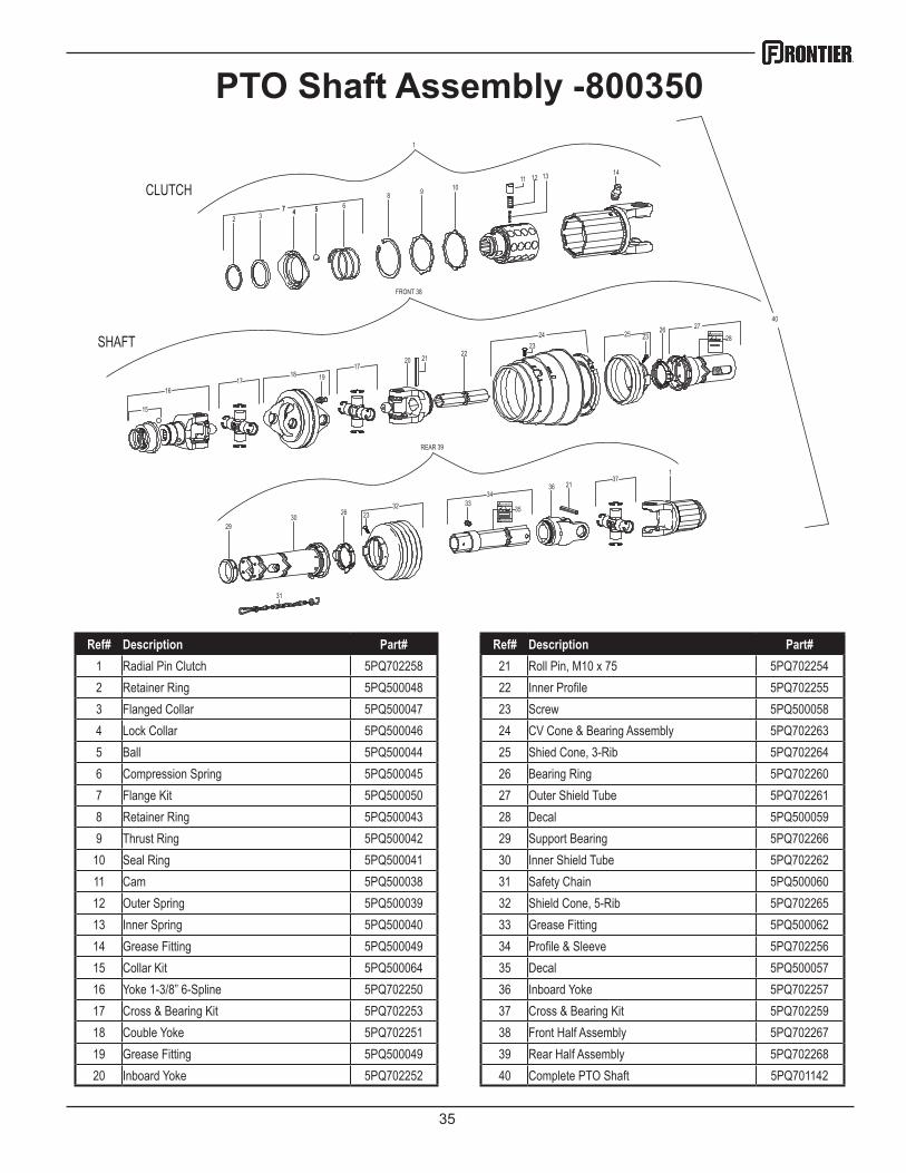
PTO Shaft Assembly -800350
CLUTCH77
255 6
443
8 9 10 11 12 13 14
40
1
SHAFT
15
1617 1918
172120
2223
262825
2724 23
FRONT 38
REAR 39
2630
31
29
3223
342136
3533
371
DANGER!
DANGER !
DANGER!
Ref# Description Part# Ref# Description Part# 1 Radial Pin Clutch 5PQ702258 21 Roll Pin, M10 x 75 5PQ7022542 Retainer Ring 5PQ500048 22 Inner Profile 5PQ7022553 Flanged Collar 5PQ500047 23 Screw 5PQ5000584 Lock Collar 5PQ500046 24 CV Cone & Bearing Assembly 5PQ7022635 Ball 5PQ500044 25 Shied Cone, 3-Rib 5PQ7022646 Compression Spring 5PQ500045 26 Bearing Ring 5PQ7022607 Flange Kit 5PQ500050 27 Outer Shield Tube 5PQ7022618 Retainer Ring 5PQ500043 28 Decal 5PQ5000599 Thrust Ring 5PQ500042 29 Support Bearing 5PQ702266
10 Seal Ring 5PQ500041 30 Inner Shield Tube 5PQ70226211 Cam 5PQ500038 31 Safety Chain 5PQ50006012 Outer Spring 5PQ500039 32 Shield Cone, 5-Rib 5PQ70226513 Inner Spring 5PQ500040 33 Grease Fitting 5PQ50006214 Grease Fitting 5PQ500049 34 Profile & Sleeve 5PQ70225615 Collar Kit 5PQ500064 35 Decal 5PQ50005716 Yoke 1-3/8” 6-Spline 5PQ702250 36 Inboard Yoke 5PQ70225717 Cross & Bearing Kit 5PQ702253 37 Cross & Bearing Kit 5PQ70225918 Couble Yoke 5PQ702251 38 Front Half Assembly 5PQ70226719 Grease Fitting 5PQ500049 39 Rear Half Assembly 5PQ70226820 Inboard Yoke 5PQ702252 40 Complete PTO Shaft 5PQ701142
36
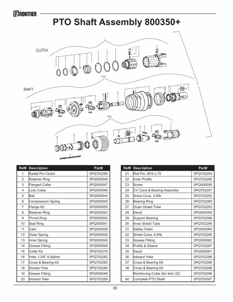
PTO Shaft Assembly 800350+
CLUTCH77
255 6
443
8 9 10 11 12 13 14
40
1
SHAFT
15
1617 1918
382120
2223
262825
2724 23
FRONT
REAR
2630
31
29
3223
342136
3533
371
DANGER!
DANGER !
DANGER!
Ref# Description Part# Ref# Description Part# 1 Radial Pin Clutch 5PQ702290 21 Roll Pin, M10 x 75 5PQ7022542 Retainer Ring 5PQ500048 22 Inner Profile 5PQ7022863 Flanged Collar 5PQ500047 23 Screw 5PQ5000584 Lock Collar 5PQ500046 24 CV Cone & Bearing Assembly 5PQ7022915 Ball 5PQ500044 25 Shied Cone, 3-Rib 5PQ7022926 Compression Spring 5PQ500045 26 Bearing Ring 5PQ7022607 Flange Kit 5PQ500050 27 Outer Shield Tube 5PQ7022938 Retainer Ring 5PQ500043 28 Decal 5PQ5000599 Thrust Ring 5PQ500042 29 Support Bearing 5PQ702266
10 Seal Ring 5PQ500041 30 Inner Shield Tube 5PQ70229411 Cam 5PQ500038 31 Safety Chain 5PQ50006012 Outer Spring 5PQ500039 32 Shield Cone, 6-Rib 5PQ70229513 Inner Spring 5PQ500040 33 Grease Fitting 5PQ50006214 Grease Fitting 5PQ500049 34 Profile & Sleeve 5PQ70228715 Collar Kit 5PQ702279 35 Decal 5PQ50006116 Yoke 1-3/8” 6-Spline 5PQ702282 36 Inboard Yoke 5PQ70228817 Cross & Bearing Kit 5PQ702283 37 Cross & Bearing Kit 5PQ70228918 Double Yoke 5PQ702284 38 Cross & Bearing Kit 5PQ70229819 Grease Fitting 5PQ500049 Reinforcing Collar (for item 32) 5PQ70229620 Inboard Yoke 5PQ702285 40 Complete PTO Shaft 5PQ702097

37
Hydraulics S/N - 800099
1
2
2
3
45
6 7 5
5
5
55
97
5
6
45
8
8
12
10
1012
11
11
8
Ref# Description Part# 1 Front Tilt Cylinder 5PQ7010702 234” Hose Assembly 5PQ7024503 Straight Fitting, 4MP-4MJ 5PQ2900124 54” Hose Assembly 5PQ7009055 Elbow Fitting, 6MB-4MJ 5PQ7009076 2x28 Cylinder 5PQ7011447 27” Hose Assembly 5PQ7009048 Straight Fitting, 6MB-4MJ 5PQ7009089 Hydraulic Manifold 5PQ700925
10 77.5” Hose Assembly 5PQ70245111 2x18 Cylinder 5PQ70235812 60.5” Hose Assembly 5PQ702452
38
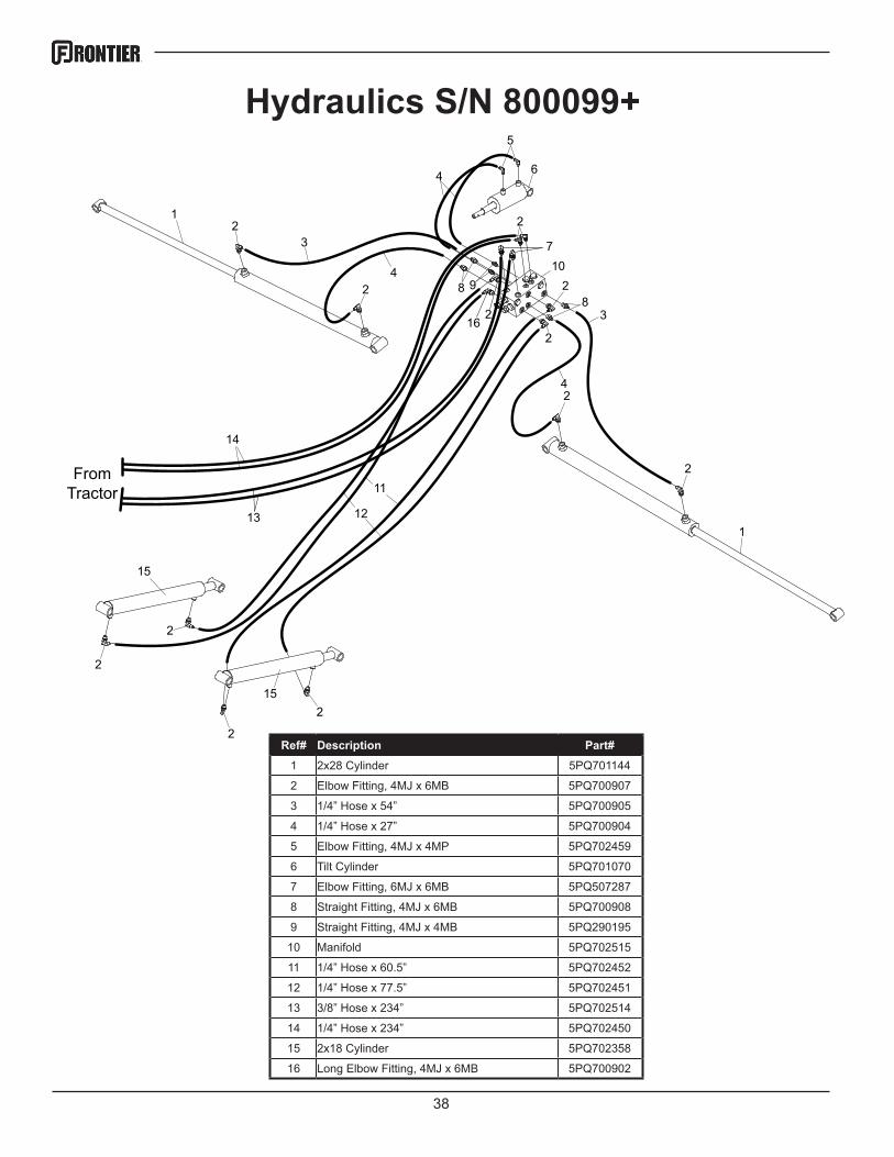
Hydraulics S/N 800099+
From Tractor
12
3 710
16
15
15
13
14
11
12
28
3
2
8 9
2
42
2
1
2
2
2
2
42
4
5
6
2
Ref# Description Part# 1 2x28 Cylinder 5PQ701144
2 Elbow Fitting, 4MJ x 6MB 5PQ700907
3 1/4” Hose x 54” 5PQ700905
4 1/4” Hose x 27” 5PQ700904
5 Elbow Fitting, 4MJ x 4MP 5PQ702459
6 Tilt Cylinder 5PQ701070
7 Elbow Fitting, 6MJ x 6MB 5PQ507287
8 Straight Fitting, 4MJ x 6MB 5PQ700908
9 Straight Fitting, 4MJ x 4MB 5PQ290195
10 Manifold 5PQ702515
11 1/4” Hose x 60.5” 5PQ702452
12 1/4” Hose x 77.5” 5PQ702451
13 3/8” Hose x 234” 5PQ702514
14 1/4” Hose x 234” 5PQ702450
15 2x18 Cylinder 5PQ702358
16 Long Elbow Fitting, 4MJ x 6MB 5PQ700902
39
1
2
3
4
5
6
7
8
9
10
11
12
13
14
16
17
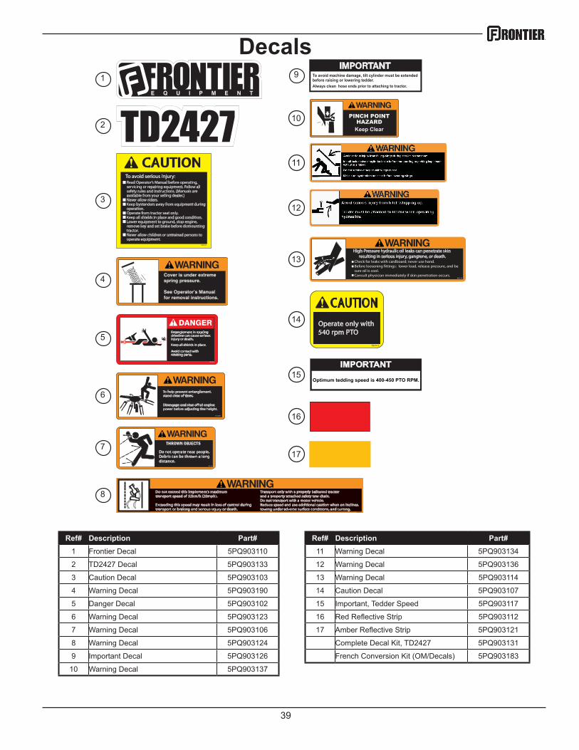
Ref# Description Part# Ref# Description Part# 1 Frontier Decal 5PQ903110 11 Warning Decal 5PQ903134
2 TD2427 Decal 5PQ903133 12 Warning Decal 5PQ903136
3 Caution Decal 5PQ903103 13 Warning Decal 5PQ903114
4 Warning Decal 5PQ903190 14 Caution Decal 5PQ903107
5 Danger Decal 5PQ903102 15 Important, Tedder Speed 5PQ903117
6 Warning Decal 5PQ903123 16 Red Reflective Strip 5PQ903112
7 Warning Decal 5PQ903106 17 Amber Reflective Strip 5PQ903121
8 Warning Decal 5PQ903124 Complete Decal Kit, TD2427 5PQ903131
9 Important Decal 5PQ903126 French Conversion Kit (OM/Decals) 5PQ903183
10 Warning Decal 5PQ903137
Decals
Optimum tedding speed is 400-450 PTO RPM.
IMPORTANT15

40