Embed Size (px)
Citation preview

MODELS 12ED
12HED 12SHED
O P E R A T I O N S MANUAL
STEEL TRUSS - ENGINE DRIVEN SCREED
LIMITED WARRANTY
Allen Engineering Corporation warrants its products to be free of defects in material or workmanship for the following periods:
A. All New Machines and Part 6 Months B. All New Gear Boxes 2 Years C. All Factory Reconditioned Gear Boxes 1 Year
Warranty period begins on first day of use by End User. This first day of use is established by a completed warranty card or a Bill of Sale to the end user. All warranty is based on the following limited warranty terms and conditions.
1. Allen Engineering Corporation’s obligation and liability under this warranty is limited to repairing or replacing parts if, after Allen’s inspection, it is determined to be a defect in material or workmanship. Allen Engineering Corporation reserves the choice to repair or replace.
2. If Allen Engineering Corporation chooses to replace the part, it will be at no cost to the customer and will be made available to the Distributor/Dealer from whom the customer purchased the product.
3. Replacement or repair parts, installed in the product, are warranted only for the remainder of warranty period of the product as though they were the original parts.
4. Allen Engineering Corporation’s warranty applies only to the products that are manufactured by Allen Engineering and does not cover component parts such as engines and clutches. Allen Engineering Corporation DOES NOT warranty clutches. Engine warranty claims should be made directly to an authorized factory service center for the particular engine make.
5. Allen Engineering Corporation’s warranty does not cover the normal maintenance of products or its components (such as engine tune-ups and oil changes). The warranty also does not cover normal wear and tear items (such as belts and consumables).
6. Allen Engineering Corporation’s warranty will be void if it is determined that the defect resulted from operator abuse, failure to perform normal maintenance on the product, modification to product, alterations or repairs made to the product without the written approval of Allen Engineering Corporation. Allen Engineering Corporation also excludes from warranty any failure of clutches on any engine driven piece of equipment.
7. If a new gear box has a factory defect within the first year of use, Allen Engineering Corporation will either repair the gear box or replace it with a new gear box. If a new gear box has a factory defect in the second year of use, Allen Engineering Corporation will either repair it or replace it with a factory reconditioned gear box. Impact damage is NOT covered under the gear box warranty.
8. Allen engineering Corporation will pay shop labor repair on warranty at the Allen Engineering Shop Labor Rate in existence on the date of the warranty claim. An Allen Engineering Labor Chart will determine the time allowed to complete a repair and will govern the shop labor hours that will be allowed.
9. Allen Engineering Corporation will pay freight on warranty replacement parts at Worldwide standard ground rates. No warranty replacement parts will be shipped air freight at the expense of Allen Engineering Corporation. Allen Engineering only pays outbound freight charges when sending warranty replacement parts to the customer VIA ground service. Allen Engineering does not pay any inbound freight, however, if Allen Engineering determines this to be warranty defect only then will Allen Engineering reimburse the customer for inbound freight at standard ground rates.
10. Allen Engineering Corporation’s warranty policy WILL NOT COVER the following; taxes, shop supplies, environmental surcharges, air freight, travel time, loss of rental revenue, or any other charges whatsoever or any liabilities for direct, incidental, or consequential damage or delay.
11. Allen Engineering Corporation makes no other warranty, expressed or implied. This limited warranty is in lieu of the warranty of merchantability and fitness. There are no other warranties that extend beyond the description on this document.
12. No Allen Engineering Corporation employee or representative is authorized to change this warranty in any way or grant any other warranty unless such change is made in writing and signed by an officer of Allen Engineering
ENGINE DRIVEN SCREED
O P E R A T I O N S MANUAL
NOTE: THIS MANUAL IS BROKEN UP INTO THE FOLLOWING PARTS
OPERATIONS SECTION 1
PARTS SECTION 2
MODELS - 12ED 12HED 12SHED
ALLEN RAZORBACK SCREEDS ARE COVERED BY ONE OR MORE OF THE FOLLOWING PATENTS:
U.S. PATENTS: 4,249,327; 4,316,715; 4,349,328; 4,363,618; 4,375,351; 4,412,803; 4,544,346; 4,630,964; 4,648,741; 4,685,826;
STEEL TRUSS

OPERATIONS SECTION 1
OPERATIONS • TABLE OF CONTENTS •
1. TABLE OF CONTENTS .................................................................................... S1-1 2. INFORMATION CONTAINED IN THIS MANUAL ............................................. S1-2 3. ORDERING INFORMATION ............................................................................. S1-2 4. SERIAL NUMBER LOCATION ......................................................................... S1-3 5. DISTRIBUTOR INFORMATION ........................................................................ S1-4 6. SAFETY NOTATIONS ...................................................................................... S1-4 7. SPARK ARRESTERS ....................................................................................... S1-4 8. OPERATING SAFETY ...................................................................................... S1-5 9. SERVICE SAFETY ............................................................................................ S1-6 10. DIMENSIONAL PICTORIALS ........................................................................... S1-7 11. TECHNICAL DATA ........................................................................................... S1-8 12. BEFORE STARTING ........................................................................................ S1-9 13. OPERATING ..................................................................................................... S1-9 14. PERIODIC MAINTENANCE SCHEDULE ......................................................... S1-10 15. LIFTING PROCEDURES .................................................................................. S1-11 16. SECTION ASSEMBLY ...................................................................................... S1-12 17. ATTACHING WINCHES TO STAKES .............................................................. S1-13 18. DETERMINING LEFT & RIGHT OF SCREED .................................................. S1-13 19. STRINGLINING ................................................................................................. S1-14 20. END HANDLE ASSEMBLY .............................................................................. S1-15
S1-1

OPERATIONS SECTION 1
S1-2
• INFORMATION CONTAINED IN THIS MANUAL •
The information contained in this manual provides important procedures to safely operate and maintain your engine driven screed. The steps that are illustrated in this manual must be followed otherwise the life of the machine could be greatly shortened due to operator neglect. Remember that a machine that is well taken care of will provide many years of trouble free operation. For your own protection and safety, always adhere to the safety warnings and notes that are pointed out in this manual. Disregard to these instructions could lead to personal injury or possibly even death. Refer to the your engine owners manual for warranty information and spare parts ordering. Allen Engineering does not warrant the engine that came with your engine driven screed.
• ORDERING PARTS •
This manual contains an illustrated parts list to help you in ordering replacement parts for your engine driven screed. Follow the instructions below carefully when ordering parts to insure that you get the exact parts that you are wanting. • All orders for service parts include a serial number. Shipment of your parts will be delayed if this
information is not available when you call Allen Engineering Customer Service.
• Include the description and correct part number from Section 2, as well as, the quantity needed.
• For prompt and accurate shipments, specify exact shipping instructions, including preferred
routing and complete destination address.
• DO NOT return parts to Allen Engineering without receiving written authorization from Allen
Engineering Corporation. All authorized returns must be shipped pre-paid.
When placing an order, contact your nearest Allen Engineering Distributor or call Customer Service at 800-643-0095 or 870-236-7751. THIS MANUAL COVERS TRUSS SCREED STARTING WITH THE FOLLOWING SERIAL NUMBERS: 2’ - HED820314, 2-1/2’ - HED830333, 5’ - HED850445, 7-1/2’ - HED671065
WHEN ORDERING ADDITIONAL COPIES OF THIS MANUAL, PLEASE SPECIFY THE PART NUMBER BELOW.
025788
P.O. BOX 819 PARAGOULD, AR 72451-0819
USA
COPYRIGHT© 1998 ALLEN ENGINEERING CORPORATION ALL RIGHTS RESERVED - CONTENTS SUBJECT TO CHANGE WITHOUT PRIOR NOTICE.
OPERATIONS SECTION 1
S1-3
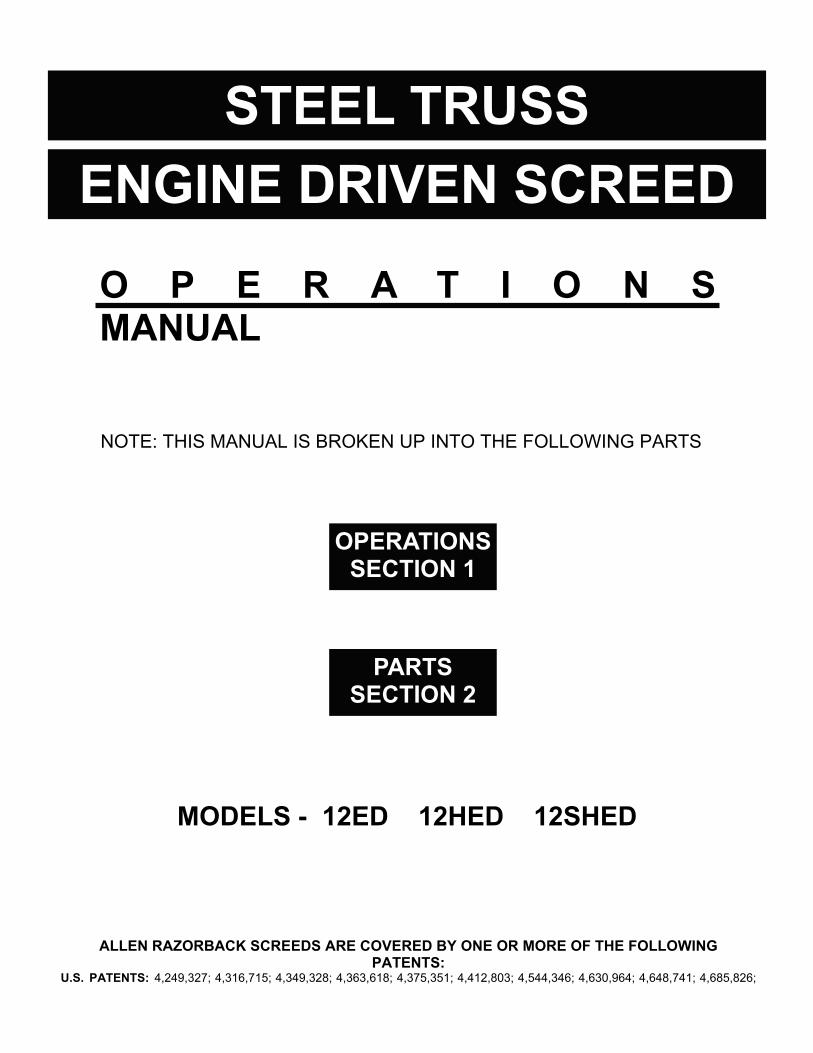
• SERIAL NUMBER LOCATION •
LOCATION OF SERIAL #
INFORMATION ON SERIAL NUMBER SAMPLE # - ED82243 ED, HD, SHED = MODEL
8 = LAST DIGIT OF PRESENT YEAR
2, 25, 5, 7 = SIZE OF TRUSS ASSEMBLY
2 = MONTH OF PRESENT YEAR
43 = SEQUENCE NUMBER OF SECTION BUILT IN
PRESENT MONTH
NOTE: EVERY SECTION THAT LEAVES ALLEN ENGINEERING HAS A SERIAL NUMBER STAMPED ON THE RIGHT HAND SIDE OF THE TRUSS TOP PIPE. WHEN ORDERING PARTS, YOU WILL BE ASKED FOR THIS SERIAL NUMBER. MAKE NOTE OF ALL YOUR SECTION SERIAL NUMBERS FOR FUTURE REFERENCE.
FILL OUT SERIAL #’S HERE FOR FUTURE REFERENCE ____________________________________________________________________________________________________________________________________________________________________________________________________________________________________________

S1-4
OPERATIONS SECTION 1 • DISTRIBUTOR INFORMATION •
PLACE DISTRIBUTOR INFORMATION HERE FOR FUTURE REFERENCE DISTRIBUTOR NAME:__________________________________PHONE #:__________________ ADDRESS:______________________________________________________________________ CITY:_________________________________________STATE:_____________ZIP:__________SALESMAN:____________________________________________________________________ ADDITIONAL COMMENTS:_________________________________________________________ __________________________________________________________________________________________________________________________________________________________________________________________________________________________________________________________________________________________________________________________________________________________________________________________________________________________________________________________________________________________
• SAFETY NOTATIONS •
NOTE: Throughout this manual, there are NOTES, CAUTIONS, and WARNINGS which must be followed to reduce the possibility of improper service damage to the equipment or personal injury. • NOTE - Contains additional information important to a procedure. • CAUTION - Provides information important to prevent errors which could damage the
machine.
• LAWS PERTAINING TO SPARK ARRESTERS •
Some states require that spark arresters be used on internal combustion engines in some locations. A spark arrester is a device designed to prevent the discharge of sparks or flames from the engine exhaust. It is often required to have a spark arrester on an engine when operating equipment on forested areas to reduce the risk of fires. Consult the engine distributor or contact the local authorities to make sure that you comply with regulations concerning spark arresters.

OPERATIONS SECTION 1
S1-5
• OPERATING SAFETY •
Familiarity and proper training are required for the safe operation of this equipment. Equipment operated improperly or by untrained personnel can damage equipment and could be dangerous. Read the operating instructions contained in both this manual and the engine manual to familiarize yourself with the location and proper use of all the controls.
DO NOT operate this machine until you have read the operating and safety instructions. Operate the machine in accordance with the manufacturer’s instructions. ALWAYS inspect your screed upon arrival for damage or tampering that can sometimes occur during shipping. If damage is found, file a claim with your carrier immediately!! Mark freight bill of lading as “damaged shipment”. NEVER allow untrained personnel to operate your engine driven screed. Individuals who operate this screed should have adequate training in operating procedures. DO NOT attempt to fill fuel or hydraulic(winch) tanks while machine is running. Allow engine to cool for five minutes before refueling. NEVER use over-the-counter hardware to replace manufacturers hardware. Contact your nearest Allen Engineering dealer or our Customer Service department. HAZARD: When operating machines with gas engines in confined areas, the fumes must be ventilated. Improper ventilation could lead to serious health problems or even death. ALWAYS be aware of HOT components on this machine, such as, engines, hydraulic components. ALWAYS be aware of the rotating drive shaft on this engine driven screed. Failure to keep away from the shaft could lead to severe injury.
OPERATIONS SECTION 1
S1-6
• SERVICE SAFETY •
DO NOT attempt to clean or service screed while machine is running. The rotating shaft could cause severe injury. DO NOT attempt to start a flooded engine with the spark plug removed on gasoline powered engines. Fuel trapped in the cylinder will squirt out of the spark plug opening. DO NOT test for spark on gasoline engines if engine is flooded or the smell of gasoline is present. A stray spark could ignite the fumes. DO NOT use gasoline, other fuels, or any flammable solvent to clean parts, especially in enclosed areas. Fumes from fuels and solvents can cause serious health problems if you are exposed to them over an extended period of time. ALWAYS keep area around muffler free of debris, such as, leaves, paper, cartons, etc. A hot muffler could ignite them starting a fire. ALWAYS disconnect spark plug before servicing engine to prevent accidental start-up.
OPERATIONS SECTION 1
S1-7
• DIMENSIONAL PICTORIALS •
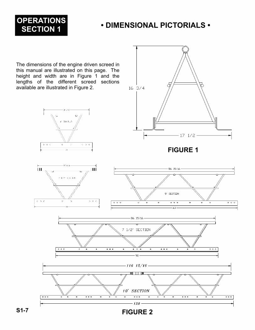
The dimensions of the engine driven screed in this manual are illustrated on this page. The height and width are in Figure 1 and the lengths of the different screed sections available are illustrated in Figure 2.
FIGURE 1
FIGURE 2

OPERATIONS SECTION 1
S1-8
• TECHNICAL DATA •
SPECIFICATIONS ON THE STEEL TRUSS FRAME:
MODEL TRUSS BLADES 10’ lbs/kg
7 1/2’ lbs/kg
5’ lbs/kg
2 1/2’ lbs/kg
2’ lbs/kg
MAXIMUM WIDTHS
12ED 12 GA. GALV. STEEL 172/79 132/50 86/39 46/21 37/17 55’
12HED 10 GA. GALV. STEEL 180/82 135/64 90/41 50/23 36/16 65’
12SHED 10 GA. STAINLESS 188/85 141/64 94/43 53/24 50/23 75’
• Top Pipe - Coupling System - Fine Thread Adjustment 1 5/16-16tpi with Full Flow 1” Non-Restricting Air System with Dual Locking Jam Nuts.
• Vibration Proof Welds with Exclusive Vibration-Dampening System. • Bolt-On Blades with Quick Connecting Splice Plates Front and Back at each Truss Section using
1/2-13 Nuts and Bolts Throughout. • Balanced Design Truss Height to Overall Base Width Provides Equilateral Triangle Strength for
Obtaining Precise Grade Control and Structure Integrity. • Top Pipe Coupling System Provides for Crowned or Invert Slab Section without loosening Bottom
Splice Blade Bolts. Special Crowns or Inverts are obtainable with Ball Joint Top Pipe Coupler or Crown Invert Bracket. Crowns greater than 1/8”/ft are considered special.
• NOTE: Select Screed Width to Allow Minimum Overhangs Past Forms; 6” Overhangs are Ideal,
SPECIFICATIONS ON THE ROTATING ECCENTRIC SHAFT (RES) VIBRATORY SCREED:
MODEL ENGINE KITS
12ED √ √ √ √ √ √ 12HED √ √ √ √ √ √
12SHED √ √ √ √ √
HONDA - 5.5 HP 8 HP 11 HP 8” END LOW PROFILE DUAL CENTRIFUGAL
• Rotating Eccentric Shaft (RES) Produces Over 8000 Vibration Cycles Per Min. • 3/4” Diameter High Alloy Steel Plated Vibratory Shaft with 1 3/8” Diameter Dual Eccentric
Vibrators Mounted on 30” Centers. Running in 3/4” Diameter Pillow Block Bearings with Shaft Locking Collars.
• ENGINE SPEED: up to 3600 RPM with throttle control. • Vibrator Shaft with Synchronization Key Way and four each Square Head Set Screws Mounted
with an Intermediate Bearing Support • Eccentric Vibrators attached to shaft with 1/4” Bolt with Stover Lock Nut. • Crowned Selections - Up Through 1/8”/ft use Flex Couplers, over 1/8”/ft Crown use U-Joint Kit.
Screeds are Shipped Standard with Rigid Shaft Couplers for Running Flat without Crowns.

OPERATIONS SECTION 1
S1-9
• BEFORE STARTING •
Before starting the engine driven screed, there are a few items that need to be looked over. • Make sure that bolts are secure and will not vibrate loose. • Check for loose set screws on all shaft couplers. • Check jam nuts on top pipe to ensure that they are tight against the top pipe coupler. • Check the oil and fuel levels in the engine. • Check the hydraulic level in the tank for the hydraulic winches (if applicable). • Check bearings for grease. NOTE: bearings are pre-greased from the manufacturer. • Check winch cables to make sure that they will not loosen during the screed run. • Look over the forms to check for unevenness so that the screed will not hang up. Ask yourselves these questions when preparing your screed for a job. • What is the “exact” pour width? • What is the slump? • Is the slab flat, crowned, or inverted? • What is the required surface tolerance? • Choose screed type and size based on the above information. • Are any accessories required? • Do the winches work properly? • Are the hydraulic pressure settings OK? • Is the drive shaft aligned properly?
• OPERATING •
Operating your engine driven screed correctly will greatly produce the outcome of the pour. Follow the instructions below to operate your screed correctly and you will be very pleased with your equipment. • Start the engine and slowly increase the throttle. • Engage or turn winch handles simultaneously to keep the screed even. • DO NOT adjust the throttle on the engine to slow down or speed up the hydraulic winches, use the flow
controls instead. • NEVER let the concrete build up on the front blade, this causes the screed to be stressed and is strenuous
on the operators controlling the manual winches. The concrete should not go above the bolts attaching the blades. If this happens stop the screed and let the vibration do its job.
• If the concrete is not being added at the appropriate rate, slow the screed down to compensate. • The speed that the screed should be operated at determines on the slump of the concrete. Pay close
attention to the aggregates, slump, and concrete modifying agents so that you can compensate for them. REMINDER! - DO NOT OVER-VIBRATE THE CONCRETE
• Make sure that when you have completed the pour(s) that you clean the screed immediately to prevent concrete from curing on the drive shaft and bearings, etc. Using an Allen Engineering High Pressure

OPERATIONS SECTION 1
S1-10
• PERIODIC MAINTENANCE SCHEDULE •
The following list contains information regarding the maintenance and operations procedures that must be adhered to improve the life of your machine. A well maintained piece of machinery will provide you years of satisfaction.
• Always make sure that the drive shaft is aligned properly. To make sure that you do this correctly you will need to utilize AEC tool part number 020255.
• When connecting drive shafts, assemble with all the weights on each section facing the bullfloat blade. If weights are mis-matched, the screed will not vibrate properly. Match the keyways on the drive shafts and the connectors.
• Do not overspeed, engine RPM must not exceed 3600 RPM. Shaft speed will not exceed design limits if engine speed maximum is adhered to.
• DO NOT crown or invert without universal joints or flex couplers on the shaft connectors.
• Maintain engine in accordance with the manufacturer’s instructions.
• Use Loctite anti-seize MIL A 907D to lubricate the top pipe coupler threads before assembly.
• Grease screed bearings at 40 hr. operating intervals. Use one stroke of a hand grease gun. Use Shell Alvonia #21, Texaco L-15, Chevron SR1. Clean fittings before greasing. For low temperatures, use Dow Molykote BR-2. DO NOT OVER GREASE.
• Oil winch bushings at 10 hr. operation intervals. Use light lubricating oil.
• CAUTION! Change worn or frayed cables - cables under tension may snap and cause severe injury. Use proper methods illustrated in this manual to properly attach cables. Always connect cables properly - wrap cable under last form pin then connect cable hook to the next form pin towards the screed.
• DO NOT hook cables to a stake driven into the ground, the stake can tilt and allow cable under tension to snap back and cause severe injury.

OPERATIONS SECTION 1
S1-11
• LIFTING PROCEDURES •
The following procedures describe proper lifting techniques for screed. There is no OSHA standard weight limit for manual lifting. Therefore, rather than stating a regulated limit, they ask that employers or contractors do the following: A) Identify each hazard to which a person at the work place (jobsite) is likely to be exposed to B) Assess the risk of injury or harm to a person resulting from each hazard C) Consider the means by which the risk may be reduced. NOTE: Never lift more than what you personally feel that you can handle.
The lifting handles at each end of the screed are not intended to be used as the only source to lift the screed. It is quite obvious that two large men will not be able to lift 70 feet of screed. The following list of maximum screed lengths is very important so that the length of your screed will not be too long. ED SCREED - MAXIMUM 55 FEET HED SCREED - MAXIMUM 65 FEET SHED SCREED - MAXIMUM 75 FEET For proper lifting of an average screed (30 ft.), the screed lifting hook is an ideal item to use. This instrument should be placed at equal distances from each end. A special lifting bridle is then used by a forklift, crane, front-end loader, etc. to raise and transport the screed. Also available from Allen Engineering is the screed cart. This item is used to move the screed around on the job site only.
LIFTING HOOK PART # 532000
STANDARD SCREED CART MAXIMUM 500 lbs. - 543000 HEAVY DUTY SCREED CART MAXIMUM 1,000 lbs. - 543001
OPERATIONS SECTION 1 • SECTION ASSEMBLY •
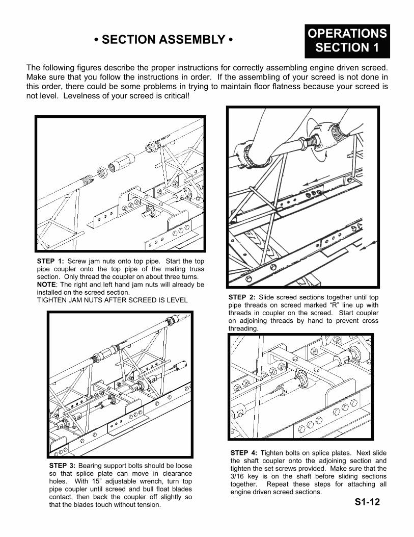
STEP 1: Screw jam nuts onto top pipe. Start the top pipe coupler onto the top pipe of the mating truss section. Only thread the coupler on about three turns. NOTE: The right and left hand jam nuts will already be installed on the screed section. TIGHTEN JAM NUTS AFTER SCREED IS LEVEL
The following figures describe the proper instructions for correctly assembling engine driven screed. Make sure that you follow the instructions in order. If the assembling of your screed is not done in this order, there could be some problems in trying to maintain floor flatness because your screed is not level. Levelness of your screed is critical!
STEP 3: Bearing support bolts should be loose so that splice plate can move in clearance holes. With 15” adjustable wrench, turn top pipe coupler until screed and bull float blades contact, then back the coupler off slightly so that the blades touch without tension.
STEP 2: Slide screed sections together until top pipe threads on screed marked “R” line up with threads in coupler on the screed. Start coupler on adjoining threads by hand to prevent cross threading.
STEP 4: Tighten bolts on splice plates. Next slide the shaft coupler onto the adjoining section and tighten the set screws provided. Make sure that the 3/16 key is on the shaft before sliding sections together. Repeat these steps for attaching all engine driven screed sections.
S1-12

OPERATIONS SECTION 1
S1-13
• ATTACHING WINCHES TO FORM STAKES •
The figure below illustrates the proper way to attach the winch cables to the form stakes. This is the only way that the cables should be attached. If the cables are not attached properly, the cables could snap loose causing severe injury to finishing personnel surrounding the screed.
To attach the winch cables properly, adhere to the following instructions.
• Take the cable and go around the last form stake. Make sure that you go underneath the form.
• Attach the cable hook to the next form stake from the end.
• A l w a y s insure that
FIRST STAKE FROM END
SECOND STAKE FROM END
WINCH CABLE
CABLE HOOK
• DETERMINING LEFT AND RIGHT OF The following illustration shows all the key information on how to determine the left and right and the front and rear of a screed section.
Note the circle with the serial number. This is probably the easiest way to determine the left and right sides of the screed assembly. The right side has the model number and the a 5-digit serial number. The left hand side is only stamped with an “L”. Also the front of the screed is determined by the two screed blades mounted back-to-back. The rear of the screed has only one bullfloat blade.

OPERATIONS SECTION 1
TOP PIPE COUPLER
JAM NUTS
S1-14
• STRING LINING •
To string line your screed, there are a few important steps that need to be followed.
• Place screed ends on a 2 x 6 or other wooden type support.
• At approximately 1” out from the leading edge of the screed blade, drive a nail into the wooden support. NOTE: Nail should be on the outside of the wooden support.
• Stretch a line as tight as possible from nail to nail. Make sure that the nail is contacting each support at the point of blade contact.
• NOTE: The supports do not have to be on the same level.
• Use a short, flat piece of metal or wood as a gauge block to compare the string to the bottom surface of the screed blade and bullfloat blade.
• The blades should be equal to each other at each splice. If they are not even, loosen jam nuts and tighten top pipe coupler as described on page S1-14.
NOTE: Always string line your

S1-15
• END HANDLE ASSEMBLY • OPERATIONS SECTION 1
The following figure shows the proper way to mount a standard end handle to the screed section. Do not try to modify this mounting procedure, this is the only way to mount the end handles where they will work properly.
END HANDLE
Follow the steps below to properly mount the end handles to your screed.
• Mount the bearing onto the bearing support bracket.
• Mount the handle grips onto the lifting handles.
• Mount the lifting handles onto the end handle using two 3/8 x 2 bolts and 3/8 nylon lock nuts.
• Mount the bearing support bracket to the end handle using four 1/4 x 1 1/2 bolts and 1/4 stover nuts.
• Mount the end handle to the screed using three 1/2 x 3/4 bolts, three 1/2 x 1 bolts and six 1/2 hex nuts. Screw the appropriate adaptor for the end you are working on onto the top pipe. Next, using

PARTS SECTION 2
S2-1
PARTS • TABLE OF CONTENTS •
1. TABLE OF CONTENTS .................................................................................... S2-1 2. ASSEMBLY OF 2’ ED SCREED SECTION ...................................................... S2-2 3. ASSEMBLY of 2-1/2’ ED SCREED SECTION ................................................. S2-3 4. ASSEMBLY of 5’ ED SCREED SECTION ........................................................ S2-4 5. ASSEMBLY of 7-1/2’ ED SCREED SECTION ................................................. S2-5 6. ASSEMBLY of 10’ ED SECTION ..................................................................... S2-6 7. END HANDLE ASSEMBLY .............................................................................. S2-7 8. WINCH ASSEMBLY ......................................................................................... S2-8 9. HYDRAULIC WINCH ASSEMBLY ................................................................... S2-9 10. LOW PROFILE MOTOR MOUNT KIT .............................................................. S2-10 11. END MOUNT ASSEMBLY ................................................................................ S2-11 12. FLEX COUPLER ASSEMBLY .......................................................................... S2-12 13. U-JOINT ASSEMBLY ....................................................................................... S2-13

• ASSEMBLY 2’ SECTION •
PART # ------------------------------- DESCRIPTION ------------------------------------------------------------------------------------ QTY. 1. 016564 ------------------------------------- 2’ TRUSS WELDMENT ------------------------------------------------------------------------------------------ 1 2. 108001 ------------------------------------- NUT, LH JAM ------------------------------------------------------------------------------------------------------- 1 3. 107000 ------------------------------------- TOP PIPE COUPLER -------------------------------------------------------------------------------------------- 1 4. 108000 ------------------------------------- NUT, RH JAM ------------------------------------------------------------------------------------------------------ 1 5. 013374 ------------------------------------- FSTN, SET SCREW 1/4-28 x 1/4 ----------------------------------------------------------------------------- 2 6. 020635 ------------------------------------- COUPLER, DRIVE SHAFT ------------------------------------------------------------------------------------- 1 7. 010273 ------------------------------------- KEY, 3/16 SQ. x 2” LONG -------------------------------------------------------------------------------------- 2 8. 020716 ------------------------------------- DRIVE SHAFT ----------------------------------------------------------------------------------------------------- 1 9. 010038 ------------------------------------- FSTN, BOLT 3/8-16 x 1 1/2 ------------------------------------------------------------------------------------ 4 10. 010005 ------------------------------------- FSTN, BOLT 1/4-20 x 1 1/2 ------------------------------------------------------------------------------------ 2 11. 020542 ------------------------------------- FSTN, NUT STOVER LOCK 1/4-20 -------------------------------------------------------------------------- 2 12. 020514 ------------------------------------- FSTN, NUT STOVER LOCK 3/8-16 -------------------------------------------------------------------------- 4 13. 010067 ------------------------------------- FSTN, BOLT 1/2-13 x 1 ----------------------------------------------------------------------------------------- 11 14. 010106 ------------------------------------- FSTN, NUT HEX 1/2-13 ----------------------------------------------------------------------------------------- 16 15. 010066 ------------------------------------- FSTN, BOLT 1/2-13 x 3/4 --------------------------------------------------------------------------------------- 5 16. 135000 ------------------------------------- BEARING SUPPORT -------------------------------------------------------------------------------------------- 1 17. 152000 ------------------------------------- 2’ ED SCREED BLADE ------------------------------------------------------------------------------------------ 2
010172 ------------------------------------- 2’ HED SCREED BLADE --------------------------------------------------------------------------------------- 2 022422 ------------------------------------- 2’ SHED SCREED BLADE ------------------------------------------------------------------------------------- 2
18. 153000 ------------------------------------- 2’ ED BULLFLOAT BLADE ------------------------------------------------------------------------------------- 1 010173 ------------------------------------- 2’ HED BULLFLOAT BLADE ----------------------------------------------------------------------------------- 1 022425 ------------------------------------- 2’ SHED BULLFLOAT BLADE --------------------------------------------------------------------------------- 1
19. 106000 ------------------------------------- BLADE SPLICE - ED SCREED ------------------------------------------------------------------------------- 2 106001 ------------------------------------- BLADE SPLICE - HED SCREED ----------------------------------------------------------------------------- 2 022430 ------------------------------------- BLADE SPLICE - SHED SCREED --------------------------------------------------------------------------- 2
20. 018999 ------------------------------------- FSTN, SET SCREW 1/4-28 x 3/8 ----------------------------------------------------------------------------- 2 21. 020704 ------------------------------------- BEARING ------------------------------------------------------------------------------------------------------------ 2 22. 010276 ------------------------------------- ECCENTRIC WEIGHT ------------------------------------------------------------------------------------------- 2
S2-2
PARTS SECTION 2
PARTS SECTION 2
S2-3
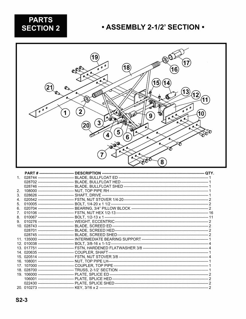
• ASSEMBLY 2-1/2’ SECTION •
PART # --------------------------- DESCRIPTION -------------------------------------------------------------------------------- QTY. 1. 028744 ---------------------------- BLADE, BULLFLOAT ED ---------------------------------------------------------------------- 1
028702 ---------------------------- BLADE, BULLFLOAT HED -------------------------------------------------------------------- 1 028746 ---------------------------- BLADE, BULLFLOAT SHED ------------------------------------------------------------------ 1
2. 108000 ---------------------------- NUT, TOP PIPE RH ----------------------------------------------------------------------------- 1 3. 028626 ---------------------------- SHAFT, DRIVE ----------------------------------------------------------------------------------- 1 4. 020542 ---------------------------- FSTN, NUT STOVER 1/4-20 ------------------------------------------------------------------ 2 5. 010005 ---------------------------- BOLT, 1/4-20 x 1 1/2 ---------------------------------------------------------------------------- 2 6. 020704 ---------------------------- BEARING, 3/4” PILLOW BLOCK ------------------------------------------------------------ 2 7. 010106 ---------------------------- FSTN, NUT HEX 1/2-13 ------------------------------------------------------------------------ 16 8. 010067 ---------------------------- BOLT, 1/2-13 x 1 --------------------------------------------------------------------------------- 11 9. 010276 ---------------------------- WEIGHT, ECCENTRIC ------------------------------------------------------------------------- 2 10. 028743 ---------------------------- BLADE, SCREED ED --------------------------------------------------------------------------- 2
028701 ---------------------------- BLADE, SCREED HED ------------------------------------------------------------------------- 2 028745 ---------------------------- BLADE, SCREED SHED ----------------------------------------------------------------------- 2
11. 135000 ---------------------------- INTERMEDIATE BEARING SUPPORT ---------------------------------------------------- 1 12. 010038 ---------------------------- BOLT, 3/8-16 x 1-1/2 ---------------------------------------------------------------------------- 4 13. 017751 ---------------------------- FSTN, HARDENED FLATWASHER 3/8 --------------------------------------------------- 4 14. 020635 ---------------------------- COUPLER, SHAFT ------------------------------------------------------------------------------ 1 15. 020514 ---------------------------- FSTN, NUT STOVER 3/8 ---------------------------------------------------------------------- 4 16. 108001 ---------------------------- NUT, TOP PIPE LH ------------------------------------------------------------------------------ 1 17. 107000 ---------------------------- COUPLER, TOP PIPE -------------------------------------------------------------------------- 1 18. 028700 ---------------------------- TRUSS, 2-1/2’ SECTION ---------------------------------------------------------------------- 1 19. 106000 ---------------------------- PLATE, SPLICE ED ----------------------------------------------------------------------------- 2
106001 ---------------------------- PLATE, SPLICE HED --------------------------------------------------------------------------- 2 022430 ---------------------------- PLATE, SPLICE SHED ------------------------------------------------------------------------- 2
20. 010273 ---------------------------- KEY, 3/16 x 2 ------------------------------------------------------------------------------------- 2

PARTS SECTION 2
S2-4
PART # ---------------------------------- DESCRIPTION ------------------------------------------------------------------------------------------ QTY. 1. 016565---------------------------------- 5’ TRUSS WELDMENT ---------------------------------------------------------------------------------- 1 2. 108001---------------------------------- NUT, LH JAM ----------------------------------------------------------------------------------------------- 1 3. 107000---------------------------------- TOP PIPE COUPLER ------------------------------------------------------------------------------------- 1 4. 108000---------------------------------- NUT, RH JAM ----------------------------------------------------------------------------------------------- 1 5. 013374---------------------------------- FSTN, SET SCREW 1/4-28 x 1/4 ---------------------------------------------------------------------- 2 6. 020635---------------------------------- COUPLER, DRIVE SHAFT ------------------------------------------------------------------------------ 1 7. 010273---------------------------------- KEY, 3/16 SQ. x 2” LONG ------------------------------------------------------------------------------- 2 8. 032112---------------------------------- DRIVE SHAFT ---------------------------------------------------------------------------------------------- 1 9. 010038---------------------------------- FSTN, BOLT 3/8-16 x 1 1/2 ----------------------------------------------------------------------------- 4 10. 010005---------------------------------- FSTN, BOLT 1/4-20 x 1 1/2 ----------------------------------------------------------------------------- 4 11. 020542---------------------------------- FSTN, NUT STOVER LOCK 1/4-20 ------------------------------------------------------------------ 4 12. 020514---------------------------------- FSTN, NUT STOVER LOCK 3/8-16 ------------------------------------------------------------------ 4 13. 010067---------------------------------- FSTN, BOLT 1/2-13 x 1 ---------------------------------------------------------------------------------- 13 14. 010106---------------------------------- FSTN, NUT HEX 1/2-13 ---------------------------------------------------------------------------------- 24 15. 010066---------------------------------- FSTN, BOLT 1/2-13 x 3/4 -------------------------------------------------------------------------------- 9 16. 135000---------------------------------- BEARING SUPPORT ------------------------------------------------------------------------------------- 1 17. 103000---------------------------------- 5’ ED SCREED BLADE ---------------------------------------------------------------------------------- 2
103001---------------------------------- 5’ HED SCREED BLADE -------------------------------------------------------------------------------- 2 022421---------------------------------- 5’ SHED SCREED BLADE ------------------------------------------------------------------------------ 2
18. 105000---------------------------------- 5’ ED BULLFLOAT BLADE ------------------------------------------------------------------------------ 1 105001---------------------------------- 5’ HED BULLFLOAT BLADE ---------------------------------------------------------------------------- 1 022424---------------------------------- 5’ SHED BULLFLOAT BLADE -------------------------------------------------------------------------- 1
19. 106000---------------------------------- BLADE SPLICE - ED SCREED ------------------------------------------------------------------------ 2 106001---------------------------------- BLADE SPLICE - HED SCREED ---------------------------------------------------------------------- 2 022430---------------------------------- BLADE SPLICE - SHED SCREED -------------------------------------------------------------------- 2
20. 018999---------------------------------- FSTN, SET SCREW 1/4-28 x 3/8 ---------------------------------------------------------------------- 2 21. 020704---------------------------------- BEARING ---------------------------------------------------------------------------------------------------- 3 22. 136000---------------------------------- STABILIZER ROD ----------------------------------------------------------------------------------------- 1 23. 010276---------------------------------- ECCENTRIC WEIGHT ----------------------------------------------------------------------------------- 4 24. 017751---------------------------------- FSTN, FLATWASHER 3/8 HARDENED ------------------------------------------------------------- 6 25. 012979---------------------------------- FSTN, NUT FLANGE 1/2 -------------------------------------------------------------------------------- 2
• ASSEMBLY 5’ SECTION •

PART # ---------------------------------------- DESCRIPTION ---------------------------------------------------------- QTY. 1. 016566 ---------------------------------------- TRUSS F/ 7-1/2’ SECTION -------------------------------------------- 1 2. 108000 ---------------------------------------- NUT, RIGHT HAND F/ TOP PIPE ------------------------------------ 1 3. 028402 ---------------------------------------- FSTN, BOLT 3/8 x 1-1/2 ------------------------------------------------ 8 4. 020542 ---------------------------------------- FSTN, NUT 1/4 STOVER LOCK -------------------------------------- 6 5. 010066 ---------------------------------------- FSTN, BOLT 1/2 x 3/4 --------------------------------------------------- 17 6. 106000 ---------------------------------------- BLADE, SPLICE - ED SCREED -------------------------------------- 2
106001 ---------------------------------------- BLADE, SPLICE - HED SCREED ------------------------------------ 2 022430 ---------------------------------------- BLADE, SPLICE - SHED SCREED ---------------------------------- 2
7. 104000 ---------------------------------------- 7-1/2’ ED BULLFLOAT BLADE --------------------------------------- 1 104001 ---------------------------------------- 7-1/2’ HED BULLFLOAT BLADE ------------------------------------- 1
8. 135000 ---------------------------------------- INTERMEDIATE BEARING SUPPORT----------------------------- 1 9. 020514 ---------------------------------------- FSTN, NUT 3/8 STOVER LOCK -------------------------------------- 8 10. 010106 ---------------------------------------- FSTN, NUT 1/2 HEX ----------------------------------------------------- 32 11. 102000 ---------------------------------------- 7-1/2’ ED SCREED BLADE -------------------------------------------- 2
102001 ---------------------------------------- 7-1/2’ HED SCREED BLADE ------------------------------------------ 2 022420 ---------------------------------------- 7-1/2’ SHED SCREED BLADE ---------------------------------------- 2
12. 010067 ---------------------------------------- FSTN, BOLT 1/2 x 1 ----------------------------------------------------- 15 13. 010005 ---------------------------------------- FSTN, BOLT 1/4 x 1-1/2 ------------------------------------------------ 6 14. 020704 ---------------------------------------- BEARING, 3/4” PILLOW BLOCK ------------------------------------- 4 15. 136000 ---------------------------------------- STABILIZER ROD -------------------------------------------------------- 2 16. 010276 ---------------------------------------- ECCENTRIC WEIGHT -------------------------------------------------- 6 17. 029041 ---------------------------------------- SHAFT F/ 7-1/2’ SECTION --------------------------------------------- 1 18. 020635 ---------------------------------------- COUPLER, SHAFT ------------------------------------------------------ 1 19. 108001 ---------------------------------------- NUT, LEFT HAND F/ TOP PIPE -------------------------------------- 1 20. 107000 ---------------------------------------- TOP PIPE COUPLER --------------------------------------------------- 1 21. 012979 ---------------------------------------- FSTN, NUT FLANGE 1/2 ----------------------------------------------- 4
• ASSEMBLY 7-1/2’ SECTION • PARTS
SECTION 2
S2-5

PARTS SECTION 2 • ASSEMBLY 10’ SECTION •
S2-6
PART # -------------------------- DESCRIPTION ----------------------------------------------------------------- QTY. 1. 010066 --------------------------- BOLT, 1/2-13 x 3/4 ------------------------------------------------------------ 22 2. 032141 --------------------------- BLADE, BULLFLOAT ED ------------------------------------------------------ 1
032139 --------------------------- BLADE, BULLFLOAT HED ---------------------------------------------------- 1 025994 --------------------------- BLADE, BULLFLOAT SHED -------------------------------------------------- 1
3. 012979 --------------------------- FSTN, NUT FLANGE 1/2-13 -------------------------------------------------- 4 4. 108000 --------------------------- NUT, TOP PIPE RH ------------------------------------------------------------ 2 5. 010273 --------------------------- KEY, 3/16 x 2 --------------------------------------------------------------------- 4 6. 020542 --------------------------- FSTN, NUT STOVER 1/4-20 ------------------------------------------------- 8 7. 010005 --------------------------- BOLT, 1/4-20 x 1 1/2 ----------------------------------------------------------- 8 8. 032140 --------------------------- BLADE, SCREED ED ---------------------------------------------------------- 2
032138 --------------------------- BLADE, SCREED HED -------------------------------------------------------- 2 025993 --------------------------- BLADE, SCREED SHED ------------------------------------------------------ 2
9. 010067 --------------------------- BOLT, 1/2-13 x 1 ---------------------------------------------------------------- 26 10. 010106 --------------------------- FSTN, NUT 1/2-13 -------------------------------------------------------------- 48 11. 020704 --------------------------- BEARING 3/4” PILLOW BLOCK --------------------------------------------- 6 12. 010038 --------------------------- BOLT, 3/8-16 x 1 1/2 ----------------------------------------------------------- 6 13. 016565 --------------------------- TRUSS, 5’ WELDMENT ------------------------------------------------------- 2 14. 032112 --------------------------- SHAFT, DRIVE 5’ 10” ---------------------------------------------------------- 2 15. 010276 --------------------------- WEIGHT, ECCENTRIC -------------------------------------------------------- 8 16. 020514 --------------------------- FSTN, NUT STOVER 3/8-16 ------------------------------------------------- 12 17. 017751 --------------------------- FSTN, FLATWASHER 3/8 HARDENED ----------------------------------- 12 18. 136000 --------------------------- ROD, STABILIZER -------------------------------------------------------------- 2 19. 106000 --------------------------- PLATE, SPLICE ----------------------------------------------------------------- 2 20. 020635 --------------------------- COUPLER, SHAFT ------------------------------------------------------------- 2 21. 135000 --------------------------- BEARING SUPPORT (INTERMEDIATE) --------------------------------- 2 22. 107000 --------------------------- COUPLER, TOP PIPE --------------------------------------------------------- 2 23. 108001 --------------------------- NUT, TOP PIPE LH ------------------------------------------------------------- 2

PARTS SECTION 2 • END HANDLE ASSEMBLY •
PART # ----------------- DESCRIPTION ------------------------------------------------------------- QTY 1. 110100 ------------------ COMPLETE RH WINCH ASSEMBLY ----------------------------------- 1
018670 ------------------ COMPLETE LH WINCH ASSEMBLY ----------------------------------- 1 2. 110101R ---------------- RH WINCH LESS CABLE -------------------------------------------------- 1
110101L ---------------- LH WINCH LESS CABLE --------------------------------------------------- 1 3. 010082 ------------------ FSTN, 5/16 FLATWASHER ------------------------------------------------ 4 4. 010023 ------------------ FSTN, BOLT 5/16-18 x 1 3/4 ---------------------------------------------- 2 5. 109000 ------------------ END HANDLE ----------------------------------------------------------------- 1 6. 010100 ------------------ FSTN, NUT 5/16 -------------------------------------------------------------- 2 7. 010088 ------------------ FSTN, 1” FLATWASHER --------------------------------------------------- 1 8. 113000 ------------------ FSTN, NUT F/ END HANDLE --------------------------------------------- 1 9. 010005 ------------------ FSTN, BOLT 1/4-20 x 1 1/2 ------------------------------------------------ 4 10. 010464 ------------------ FSTN, NUT NYLON LOCK 3/8-16 --------------------------------------- 2 11. 015767 ------------------ HANDLE GRIP ---------------------------------------------------------------- 2 12. 017066 ------------------ LIFTING HANDLE ------------------------------------------------------------ 2 13. 010040 ------------------ FSTN, BOLT 3/8-16 x 2 ----------------------------------------------------- 2 14. 112000 ------------------ BEARING SUPPORT BRACKET ----------------------------------------- 1 15. 020704 ------------------ BEARING ----------------------------------------------------------------------- 1 16. 010106 ------------------ FSTN, NUT HEX 1/2-13 ----------------------------------------------------- 6 17. 010085 ------------------ FSTN, 1/2 FLATWASHER -------------------------------------------------- 1 18. 110005 ------------------ PULLEY BLOCK W/ EYEBOLT ------------------------------------------- 1 19. 012391 ------------------ CABLE CLAMP --------------------------------------------------------------- 1 20. 110008 ------------------ SLIP HOOK -------------------------------------------------------------------- 1 21. 110103 ------------------ CABLE F/ WINCH (1/8 AIRCRAFT) ------------------------------------- 100 ft. 22. 020542 ------------------ FSTN, NUT STOVER LOCK 1/4-20 ------------------------------------- 4 23. 114000 ------------------ ADAPTOR, R.H. AIR END ------------------------------------------------- 1
115000 ------------------ ADAPTOR, L.H. AIR END -------------------------------------------------- 1 24. 010066 ------------------ FSTN, BOLT 1/2-13 x 3/4 --------------------------------------------------- 3 S2-7

PARTS SECTION 2
S2-8
• WINCH ASSEMBLY •
PART # -------------------------------- DESCRIPTION ----------------------------------------------------------------------- QTY 1. 250002 --------------------------------- BUSHING --------------------------------------------------------------------------------- 2 2. 250003 --------------------------------- E-RING ------------------------------------------------------------------------------------ 2 3. 250022 --------------------------------- INTERMEDIATE DRIVE SHAFT --------------------------------------------------- 1 4. 250014 --------------------------------- SHAFT REEL ---------------------------------------------------------------------------- 1 5. 012826 --------------------------------- SPACER ---------------------------------------------------------------------------------- 1 6. 250024 --------------------------------- BUSHING --------------------------------------------------------------------------------- 2 7. 120013 --------------------------------- FSTN, BOLT CARRAGE 1/4 x 3/4 ------------------------------------------------- 1 8. 250017 --------------------------------- WINCH REEL 2 1/2 DIA -------------------------------------------------------------- 1 9. 120012 --------------------------------- CABLE CLAMP ------------------------------------------------------------------------- 1 10. 120011 --------------------------------- FSTN, NUT HEX 1/4 ------------------------------------------------------------------- 1 11. 120015 --------------------------------- FSTN, STOVER LOCK 3/8----------------------------------------------------------- 1 12. 250009 --------------------------------- SLEEVE RATCHET -------------------------------------------------------------------- 1 13. 120017 --------------------------------- COMPRESSION SPRING ------------------------------------------------------------ 1 14. 120018 --------------------------------- LEVER RATCHET ---------------------------------------------------------------------- 1 15. 020471 --------------------------------- PLATE, LATCH LH --------------------------------------------------------------------- 1
250026 --------------------------------- PLATE, LATCH RH -------------------------------------------------------------------- 1 16. 250007 --------------------------------- BOLT, RATCHET ----------------------------------------------------------------------- 1 17. 250001 --------------------------------- BASE WINCH, 2500 ------------------------------------------------------------------- 1 18. 250025 --------------------------------- SPACER ---------------------------------------------------------------------------------- 1 19. 250006 --------------------------------- DRIVE SHAFT --------------------------------------------------------------------------- 1 20. 120021 --------------------------------- SPRING EXTENSION ----------------------------------------------------------------- 1 21. 120020 --------------------------------- PAWL RATCHET ----------------------------------------------------------------------- 1 22. 110102 --------------------------------- HANDLE ---------------------------------------------------------------------------------- 1 23. 120016 --------------------------------- FSTN, NUT STOVER LOCK 1/4 --------------------------------------------------- 1 24. 110101R ------------------------------- HD WINCH RH (WINCH ONLY) ---------------------------------------------------- 1 25. 110101L ------------------------------- HD WINCH LH (WINCH ONLY) ---------------------------------------------------- 1
DL2500 WINCH

PARTS SECTION 2 • HYDRAULIC WINCH ASSEMBLY •
RH WINCH SHOWN
PART # -------------------------------------- DESCRIPTION -------------------------------------------------------------- QTY 1. 029109 --------------------------------------- ROD, SPRING ----------------------------------------------------------------- 1 2. 010098 --------------------------------------- FSTN, NUT 1/4-20 ------------------------------------------------------------ 2 3. 029108 --------------------------------------- SPRING, F/ HYD WINCH --------------------------------------------------- 1 4. 027898L & R -------------------------------- REEL ASSEMBLY ------------------------------------------------------------ 1 5. 022656 --------------------------------------- CABLE CLAMP ---------------------------------------------------------------- 2 6. 110008 --------------------------------------- SLIP HOOK --------------------------------------------------------------------- 1 7. 010039 --------------------------------------- FSTN, BOLT 3/8 x 1-3/4 ----------------------------------------------------- 2 8. 029112 --------------------------------------- REEL BRACKET -------------------------------------------------------------- 1 9. 034011 --------------------------------------- MOTOR, HYDRAULIC ------------------------------------------------------- 1 10. 000751 --------------------------------------- CABLE 1/8” (AIRCRAFT STYLE) ----------------------------------------- 100’ 11. 010036 --------------------------------------- FSTN, BOLT 3/8-16 x 1 ------------------------------------------------------ 4 12. 017751 --------------------------------------- FSTN, 3/8 FLATWASHER HARDENED --------------------------------- 4 13. 027906L & R -------------------------------- HANDLE, MANUAL WINCH ------------------------------------------------ 1 14. 013757 --------------------------------------- VALVE BLOCK ---------------------------------------------------------------- 1 15. 010005 --------------------------------------- FSTN, BOLT 1/4-20 x 1 1/2 ------------------------------------------------- 4 16. 010081 --------------------------------------- FSTN, 1/4 FLATWASHER -------------------------------------------------- 8 17. 017751 --------------------------------------- FSTN, 3/8 FLATWASHER HARDENED --------------------------------- 4 18. 010464 --------------------------------------- FSTN, NUT NYLON 3/8 ----------------------------------------------------- 2 19. 020542 --------------------------------------- FSTN, NUT STOVER 1/4-20 ----------------------------------------------- 4 20. 029105L & R -------------------------------- PUMP, HYDRAULIC ---------------------------------------------------------- 1 21. 010019 --------------------------------------- FSTN, BOLT 5/16-18 x 3/4 -------------------------------------------------- 4 22. 027903 --------------------------------------- PUMP COVER ----------------------------------------------------------------- 1 23. 029117 --------------------------------------- TANK, HYDRAULIC (RH) --------------------------------------------------- 1
029116 --------------------------------------- TANK, HYDRAULIC (LH) ---------------------------------------------------- 1 24. 034013 --------------------------------------- CAP, FILLER BREATHER -------------------------------------------------- 1 25. 010109 --------------------------------------- FSTN, NUT NYLON 5/16-18 ----------------------------------------------- 4 26. 010021 --------------------------------------- FSTN, BOLT 5/16 x 1 1/4 --------------------------------------------------- 4 27. 010500 --------------------------------------- PULLEY 1/2” ------------------------------------------------------------------- 1 28. 026486 --------------------------------------- V-BELT --------------------------------------------------------------------------- 1 29. 011896 --------------------------------------- PULLEY 3/4” ------------------------------------------------------------------- 1 30. 010090 --------------------------------------- FSTN, HARD LOCKWASHER 5/16 --------------------------------------- 8 31. 029114 --------------------------------------- PUMP BRACKET-------------------------------------------------------------- 1 32. 029111 --------------------------------------- PLATE ---------------------------------------------------------------------------- 1 33. 010106 --------------------------------------- FSTN, NUT 1/2-13 ------------------------------------------------------------ 1 34. 025992 --------------------------------------- PULLEY BLOCK HD W/ EYEBOLT--------------------------------------- 1 35. 010100 --------------------------------------- FSTN, NUT 5/16 --------------------------------------------------------------- 4 36. 010085 --------------------------------------- FSTN, FLATWASHER 1/2 -------------------------------------------------- 1 37. 010035 --------------------------------------- FSTN, BOLT 3/8 x 3/4 -------------------------------------------------------- 1
RH WINCH 027847R
LH WINCH 027847L
S2-9

• LOW PROFILE ENGINE KIT • PARTS
SECTION 2
PART# ------------------------ DESCRIPTION ------------------------------------------------------------------- QTY. 1. 027872 ----------------------- ENGINE MOUNT F/ 8 HP ENGINE ------------------------------------------- 1
028101 ----------------------- ENGINE MOUNT F/ 5 HP ENGINE ------------------------------------------- 1 2. 027884 ----------------------- CLAMP, LOPRO ENGINE MOUNT ------------------------------------------- 4 3. 027885 ----------------------- SPACER, F/ CLAMP -------------------------------------------------------------- 4 4. 027883 ----------------------- BUSHING, RUBBER SPLIT ----------------------------------------------------- 2 5. 020698 ----------------------- PULLEY, 2BK30 x 3/4” ----------------------------------------------------------- 1 6. 010066 ----------------------- BOLT, 1/2 x 3/4 --------------------------------------------------------------------- 2 7. 011490 ----------------------- FSTN, FLATWASHER 1/2” ------------------------------------------------------ 2 8. 012725 ----------------------- RUBBER ISOLATOR ------------------------------------------------------------- 2 9. 027871 ----------------------- BRACKET, ANGLE ---------------------------------------------------------------- 1 10. 011490 ----------------------- FSTN, FLATWASHER 1/2” ------------------------------------------------------ 2 11. 010066 ----------------------- BOLT, 1/2 x 3/4 --------------------------------------------------------------------- 2 12. 010081 ----------------------- FSTN, FLATWASHER 1/4” ------------------------------------------------------ 4 13. 010002 ----------------------- BOLT, 1/4 x 3/4 --------------------------------------------------------------------- 4 14. 027877 ----------------------- BELT GUARD F/ 8 HP ENGINE ----------------------------------------------- 1
028102 ----------------------- BELT GUARD F/ 5 HP ENGINE ----------------------------------------------- 1 15. 010090 ----------------------- FSTN, LOCKWASHER 5/16” --------------------------------------------------- 4 16. 012974 ----------------------- BOLT, 5/16 x 3/4 ------------------------------------------------------------------- 4 17. 126003 ----------------------- CLUTCH, 1” BORE 2 GRV. 1300 F/ 8 HP ENGINE ---------------------- 1
100620 ----------------------- CLUTCH, 3/4” BORE 2 GRV. 1075 F/ 5 HP ENGINE -------------------- 1 18. 027878 ----------------------- BELT GUARD BRACKET -------------------------------------------------------- 1 19. 027882 ----------------------- BOLT, 3/8 x 3-3/4 ------------------------------------------------------------------ 4 20. 017751 ----------------------- FSTN, FLATWASHER 3/8” ------------------------------------------------------ 4 21. 010102 ----------------------- FSTN, NUT HEX 3/8 -------------------------------------------------------------- 4 22. 028328 ----------------------- V-BELT, B39 F/ 5.3 & 5.5 HP ENGINE (NOT SHOWN) ----------------- 2
027917 ----------------------- V-BELT, B40 F/ 8 & 9 HP ENGINES (NOT SHOWN) -------------------- 2 028325 ----------------------- V-BELT, B42 F/ 11 HP ENGINE (NOT SHOWN) -------------------------- 2
S2-10

• END MOUNT ENGINE ASSEMBLY • PARTS
SECTION 2
PART # DESC. QTY 1. 020203 ---- ENGINE 5.5 HP ----- 1*
020426 ---- ENGINE 8 HP ------- 1 2. 126001 ---- HANDLE -------------- 1 3. 010273 ---- KEY -------------------- 1 4. 100620 ---- CLUTCH -------------- 1*
126003 ---- CLUTCH -------------- 1 5. NOT USED 6. 010082 ---- WASHER FLAT ----- 1*
010084 ---- WASHER FLAT ----- 1 7. 020829 ---- BOLT 5/16 x 1 3/4 -- 1*
017898 ---- BOLT 7/16 x 1 1/2 -- 1 8. 010100 ---- NUT HEX 5/16 ------ 4*
010102 ---- NUT HEX 3/8 -------- 4 9. 010090 ---- WASHER LOCK ---- 4*
010091 ---- WASHER LOCK ---- 4 10. 010082 ---- WASHER FLAT ----- 8*
010083 ---- WASHER FLAT ----- 8 11. 114000 ---- R.H. ADAPTOR ----- 1 12. 113000 ---- NUT, END ------------ 1 13. 010088 ---- WASHER ------------- 1 14. 020514 ---- NUT STOVER 3/8 -- 2 15. 027483 ---- ENGINE MOUNT --- 1* 16. SEE BELOW 17. SEE BELOW 18. 010066 ---- BOLT 1/2 x 3/4 ------ 6 19. 010067 ---- BOLT 1/2 x 1 -------- 6 20. 010106 ---- NUT, HEX 1/2 ------- 12 21. 010273 ---- KEY -------------------- 1 22. 020720 ---- V-BELT ---------------- 2 23. 020698 ---- PULLEY --------------- 1 24. 010023 ---- BOLT 5/16 x 1 3/4 -- 4*
010039 ---- BOLT 3/8 x 1 3/4 --- 4 25. 010040 ---- BOLT 3/8 x 2 -------- 2 26. 010464 ---- NUT, NYLON -------- 2 27. 017066 ---- HANDLE -------------- 2 28. 015767 ---- GRIP, HANDLE ----- 2 29. 124000 ---- THROTTLE ASS’Y - 1 30. 010002 ---- BOLT 1/4 x 3/4 ------ 2 31. 020542 ---- NUT, STOVER ------ 2 32. 020983 ---- MUFFLER ------------ 1 33. 010083 ---- WASHER FLAT ----- 4 34. 010091 ---- WASHER LOCK ---- 4 35. 010102 ---- NUT, HEX ------------ 4 36. 010038 ---- BOLT 3/8 x 1 1/2 --- 2
NOTE: * = ONLY USED ON 5.5 HP ENGINE
16. 102003-------- BLADE, SCREED 18” (12 GA.) ----------------------------- 2 018655-------- BLADE, SCREED 18” (10 GA.) ----------------------------- 2
17. 104003-------- BLADE, BULLFLOAT 18” (12 GA.) ------------------------ 1 018656-------- BLADE, BULLFLOAT 18” (10 GA.) ------------------------ 1
S2-11
• FLEX COUPLER ASSEMBLY • PARTS
SECTION 2
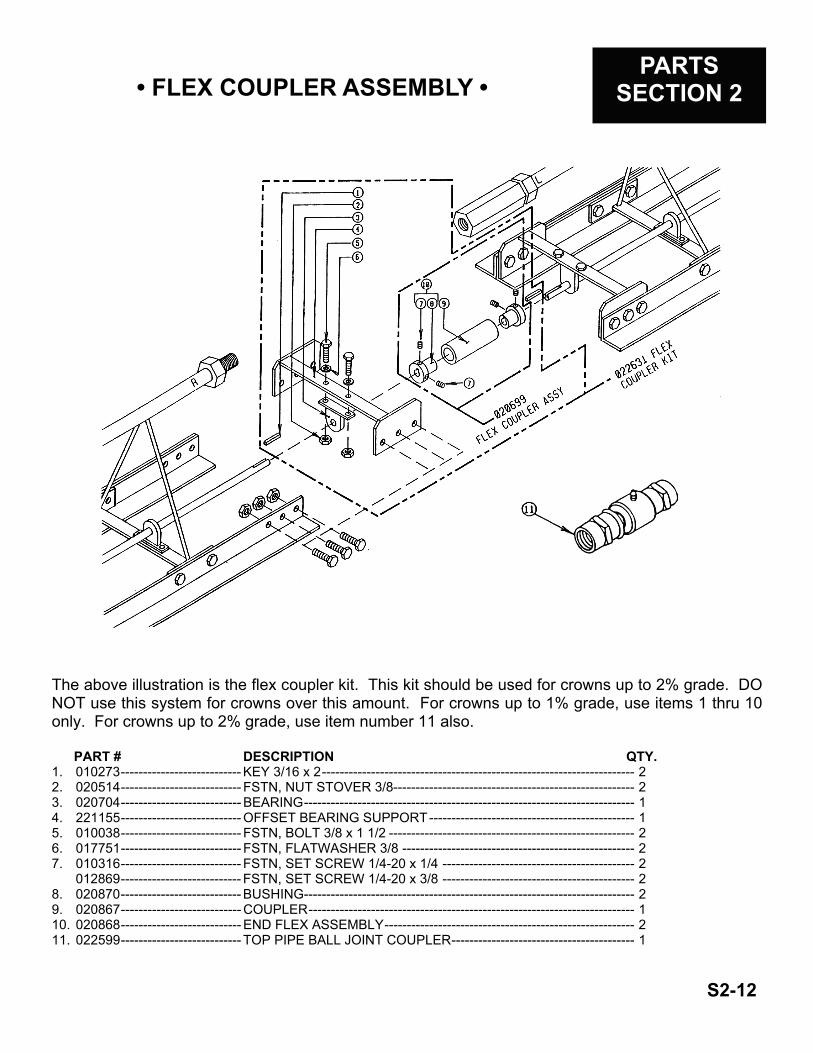
The above illustration is the flex coupler kit. This kit should be used for crowns up to 2% grade. DO NOT use this system for crowns over this amount. For crowns up to 1% grade, use items 1 thru 10 only. For crowns up to 2% grade, use item number 11 also. PART # DESCRIPTION QTY. 1. 010273 --------------------------- KEY 3/16 x 2 ---------------------------------------------------------------------- 2 2. 020514 --------------------------- FSTN, NUT STOVER 3/8------------------------------------------------------ 2 3. 020704 --------------------------- BEARING -------------------------------------------------------------------------- 1 4. 221155 --------------------------- OFFSET BEARING SUPPORT ---------------------------------------------- 1 5. 010038 --------------------------- FSTN, BOLT 3/8 x 1 1/2 ------------------------------------------------------- 2 6. 017751 --------------------------- FSTN, FLATWASHER 3/8 ---------------------------------------------------- 2 7. 010316 --------------------------- FSTN, SET SCREW 1/4-20 x 1/4 ------------------------------------------- 2
012869 --------------------------- FSTN, SET SCREW 1/4-20 x 3/8 ------------------------------------------- 2 8. 020870 --------------------------- BUSHING -------------------------------------------------------------------------- 2 9. 020867 --------------------------- COUPLER ------------------------------------------------------------------------- 1 10. 020868 --------------------------- END FLEX ASSEMBLY -------------------------------------------------------- 2 11. 022599 --------------------------- TOP PIPE BALL JOINT COUPLER ----------------------------------------- 1
S2-12

• U-JOINT ASSEMBLY • PARTS
SECTION 2
PART# --------------------------- DESCRIPTION ----------------------------------------------------------------- QTY. 1. 022635 -------------------------- U-JOINT ASSEMBLY ----------------------------------------------------------- 1 2. 028402 -------------------------- BOLT, 3/8 x 1 1/2 ----------------------------------------------------------------- 4 3. 020704 -------------------------- BEARING, 3/4” -------------------------------------------------------------------- 2 4. 221155 -------------------------- OFFSET BEARING SUPPORT ----------------------------------------------- 2 5. 010273 -------------------------- KEY, 3/16 x 2 ---------------------------------------------------------------------- 2 6. 017751 -------------------------- FSTN, FLATWASHER 3/8 ----------------------------------------------------- 4 7. 020514 -------------------------- FSTN, NUT STOVER 3/8 ------------------------------------------------------ 4
NOTE: ALWAYS CUT OFF 1” OF THE TWO ADJOINING SECTIONS TO MAKE READY FOR THE U-JOINT ASSEMBLY.
S2-13

Look for these other products at you local Allen Engineering distributor:
RIDING TROWELS HIGH PERFORMANCE SERIES HP-100 HP-200 HP-300 SUPER PROFESSIONAL SERIES SUPER PRO 500 PROFESSIONAL SERIES PRO-750 PRO-900 PRO-1050 PRO-1200 AUTOMATIC GRADE CONTROL SCREEDS STEEL POWER SCREEDS 12 SX 12 HD 12 SHD 12 ED 12 HED 12 SHED ALUMINUM POWER SCREEDS 12 ECA 12 ECS 10 QX
MAGIC SCREEDS PORTA SCREEDS POWER FLOATERS ROLLER FINISHERS HAND TOOLS MATERIAL SPREADERS WALK-BEHIND TROWELS 430 436 446 446SD GREEN CONCRETE SAWS POWER SPRAYERS HIGH PRESSURE WASHERS DIAMOND HEAD GRINDERS VIBRATORS FLEX SHAFTS TWO CYCLE BACKPACKS FOUR CYCLE BACKPACKS HBMS GENERATORS HANDY-VIBS CONVERTORS INVERTERS ARIES FORMS