Embed Size (px)
Citation preview
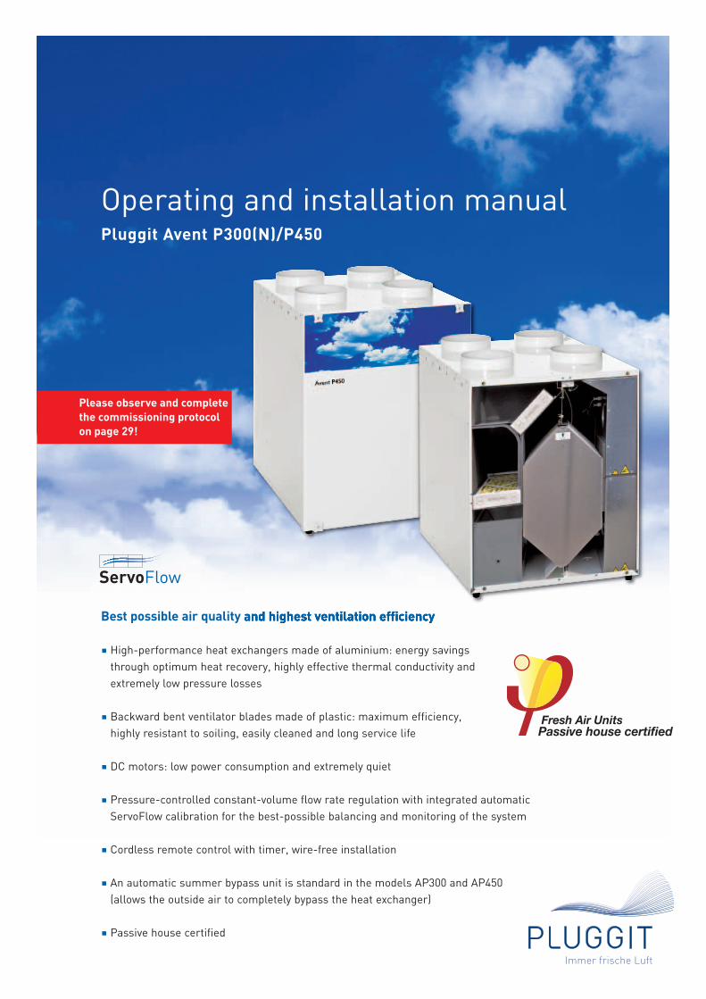
Best possible air quality and highest ventilation efficiency
High-performance heat exchangers made of aluminium: energy savingsthrough optimum heat recovery, highly effective thermal conductivity andextremely low pressure losses
Backward bent ventilator blades made of plastic: maximum efficiency, highly resistant to soiling, easily cleaned and long service life
DC motors: low power consumption and extremely quiet
Pressure-controlled constant-volume flow rate regulation with integrated automaticServoFlow calibration for the best-possible balancing and monitoring of the system
Cordless remote control with timer, wire-free installation
An automatic summer bypass unit is standard in the models AP300 and AP450 (allows the outside air to completely bypass the heat exchanger)
Passive house certified
Operating and installation manualPluggit Avent P300(N)/P450
Please observe and completethe commissioning protocolon page 29!
ServoFlow
TABLE OF CONTENTS
Remote-control quick guide Page 3
General/remote control Page 4
Important information in brief Page 5
Safety information Page 5
Notes for the technician Page 6
General Page 6
Installation location Page 6
Unpacking Page 6
Assembly steps Page 7
Commissioning Page 9
Remote control symbols Page 9
Commissioning Page 9
Calibration Page 10
Setting the volume flow rate Page 10
Viewing parameter and factory settings Page 11
Setting the weekly programme Page 12
Deleting a weekly programme Page 14
Replacing filters Page 14
Setting the summer bypass Page 15
Frost protection Page 15
Combined use with heating appliances Page 16
Optional Page 16
Additional remote control Page 18
Cleaning and replacing the heat exchanger Page 18
Removing/replacing the ventilator fans Page 19
Replacing a PCB Page 19
Pressure sensors Page 19
Temperature sensor resistances Page 19
Fault alarms/error codes Page 20
Maintenance procedures for ventilation units Page 23
Technical data Page 23
Wiring diagram Page 24
Dimensions Page 25
Declaration of Conformity Page 27
Filter maintenance record Page 28
Commissioning protocol Page 29
Spare parts Page 30
Notes Page 31
2 | BIA Avent P300(N)/450
Immer frische Luft
3 | BIA Avent P300(N)/450
Immer frische Luft
REMOTE-CONTROL QUICK GUIDE
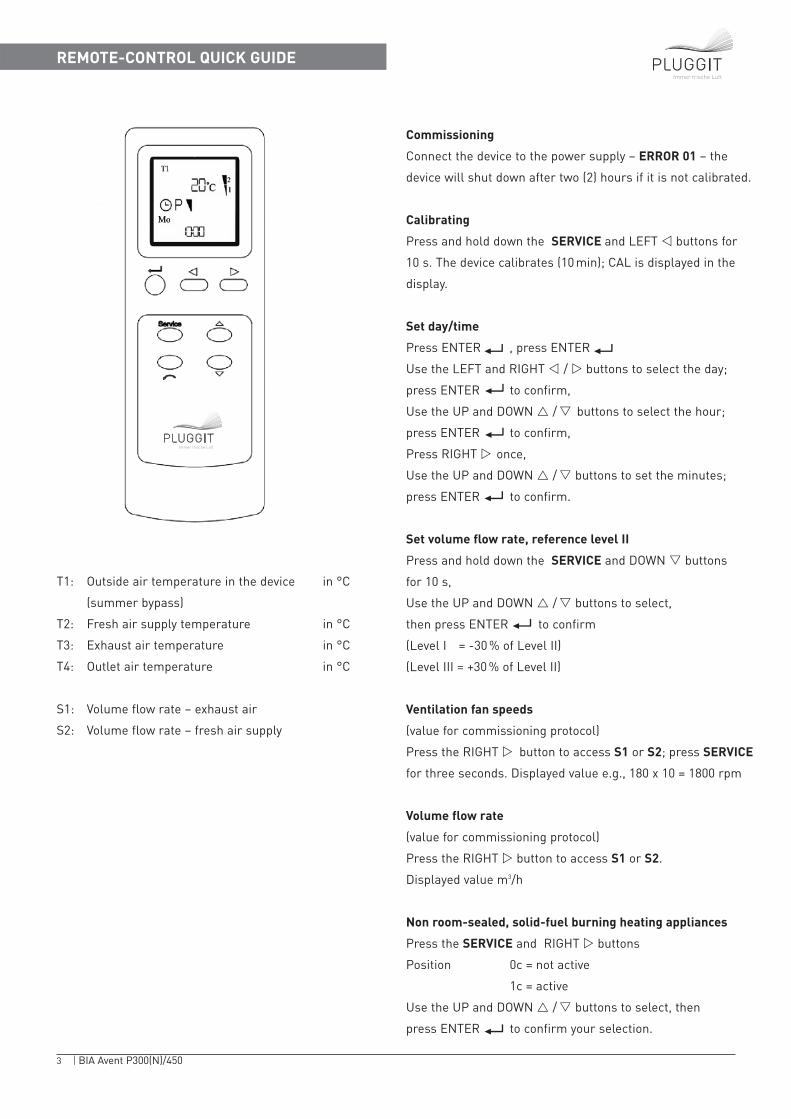
Commissioning
Connect the device to the power supply – ERROR 01 – the
device will shut down after two (2) hours if it is not calibrated.
Calibrating
Press and hold down the SERVICE and LEFT � buttons for
10 s. The device calibrates (10 min); CAL is displayed in the
display.
Set day/time
Press ENTER , press ENTER
Use the LEFT and RIGHT � / � buttons to select the day;
press ENTER to confirm,
Use the UP and DOWN � /� buttons to select the hour;
press ENTER to confirm,
Press RIGHT � once,
Use the UP and DOWN � /� buttons to set the minutes;
press ENTER to confirm.
Set volume flow rate, reference level II
Press and hold down the SERVICE and DOWN � buttons
for 10 s,
Use the UP and DOWN � /� buttons to select,
then press ENTER to confirm
(Level I = -30 % of Level II)
(Level III = +30 % of Level II)
Ventilation fan speeds
(value for commissioning protocol)
Press the RIGHT � button to access S1 or S2; press SERVICE
for three seconds. Displayed value e.g., 180 x 10 = 1800 rpm
Volume flow rate
(value for commissioning protocol)
Press the RIGHT � button to access S1 or S2.
Displayed value m3/h
Non room-sealed, solid-fuel burning heating appliances
Press the SERVICE and RIGHT � buttons
Position 0c = not active
1c = active
Use the UP and DOWN � /� buttons to select, then
press ENTER to confirm your selection.
T1: Outside air temperature in the device in °C
(summer bypass)
T2: Fresh air supply temperature in °C
T3: Exhaust air temperature in °C
T4: Outlet air temperature in °C
S1: Volume flow rate – exhaust air
S2: Volume flow rate – fresh air supply
Immer frische Luft
4 | BIA Avent P300(N)/450
GENERAL
GENERAL/REMOTE CONTROL
Immer frische Luft
Avent P fresh air units with heat recovery functionality pro-vide ventilation for dwelling areas and remove used air fromso-called wet-rooms such as bathrooms, toilets and kitchens. This means that the planned and required mini-mum air change is guaranteed through a constant supply offresh air. At the same time this prevents mould forming anddamage due to damp.
Without a fresh air unit you would have to open all the windows every two hours to achieve the same result.
Damp, stale and contaminant laden air is extracted. Theheat contained within this air is used to heat the fresh inco-ming air. Please note that heat recovery can only work pro-perly if the building is well sealed and the windows closed.
However, it is still possible to air rooms quickly by openingthe window if the rate at which the air is changed is not sufficient for any particular reason (cigarette smoke, kit-chen smells, party …).
The system should not be used during the building phase asthe ductwork, filters and ventilator fans can become soiledwith building dust. The system should be commissionedafter all other installation work has been completed.Furthermore, the device was not designed to dry-out newlybuilt structures. There is too much condensation duringthis phase; intensive heating is necessary in addition to thorough airing by opening the windows or a special dehumidifier has to be used. Please seek advice from yourarchitect.
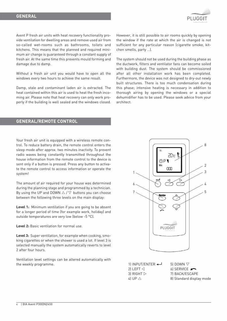
Your fresh air unit is equipped with a wireless remote con-trol. To reduce battery drain, the remote control enters thesleep mode after approx. two minutes inactivity. To preventradio waves being constantly transmitted throughout thehouse information from the remote control to the device issent only if a button is pressed. Press any button to activa-te the remote control to access information or operate thesystem!
The amount of air required for your house was determinedduring the planning stage and programmed by a technician.By using the UP and DOWN � /� buttons you can choosebetween the following three levels on the main display:
Level 1: Minimum ventilation if you are going to be absentfor a longer period of time (for example work, holiday) andoutside temperatures are very low (below -5 °C).
Level 2: Basic ventilation for normal use.
Level 3: Super ventilation, for example when cooking, smo-king cigarettes or when the shower is used a lot. If level 3 isselected manually the system automatically reverts to level2 after four hours.
Ventilation level settings can be altered automatically withthe weekly programme. 1) INPUT/ENTER 5) DOWN �
2) LEFT � 6) SERVICE3) RIGHT � 7) BACK/ESCAPE4) UP � 8) Standard display mode
Immer frische Luft
8
2
1
6
7
3
4
5
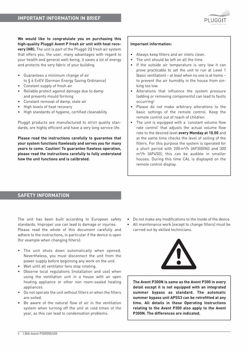
The unit has been built according to European safety standards. Improper use can lead to damage or injuries.Please read the whole of this document carefully and adhere to the instructions, in particular if the device is open(for example when changing filters):
• The unit shuts down automatically when opened.Nevertheless, you must disconnect the unit from thepower supply before beginning any work on the unit.
• Wait until all ventilator fans stop rotating.• Observe local regulations (installation and use) when
using the ventilation unit in a house with an open heating appliance or other non room-sealed heatingappliances.
• Do not operate the unit without filters or when the filtersare soiled.
• Be aware of the natural flow of air in the ventilationsystem when turning off the unit at cold times of theyear, as this can lead to condensation problems.
• Do not make any modifications to the inside of the device.• All maintenance work (except to change filters) must be
carried out by skilled technicians.
We would like to congratulate you on purchasing thishigh-quality Pluggit Avent P fresh air unit with heat reco-very (HR). The unit is part of the Pluggit 2Q fresh air systemthat offers you, the user, many advantages with regard toyour health and general well-being, it saves a lot of energyand protects the very fabric of your building.
• Guarantees a minimum change of air to § 6 EnEV (German Energy Saving Ordinance)
• Constant supply of fresh air• Reliable protect against damage due to damp
and prevents mould forming• Constant removal of damp, stale air• High levels of heat recovery• High standards of hygiene, certified cleanability
Pluggit products are manufactured to strict quality stan-dards, are highly efficient and have a very long service life.
Please read the instructions carefully to guarantee thatyour system functions flawlessly and serves you for manyyears to come. Caution! To guarantee flawless operation,please read the instructions carefully to fully understandhow the unit functions and is calibrated.
5 | BIA Avent P300(N)/450
Immer frische Luft
IMPORTANT INFORMATION IN BRIEF
�
SAFETY INFORMATION
Important information:
• Always keep filters and air inlets clean.• The unit should be left on all the time.• If the outside air temperature is very low it can
prove practicable to set the unit to run at Level 1(basic ventilation) – at least when no one is at home –to prevent the air humidity in the house from sin-king too low.
• Alterations that influence the system pressure(adding or removing components) can lead to faultsoccurring!
• Please do not make arbitrary alterations to thebasic settings of the remote control. Keep theremote control out of reach of children.
• The unit is equipped with a ‘constant volume flowrate control’ that adjusts the actual volume flowrate to the desired level every Monday at 10.00 andat the same time checks the level of soiling of thefilters. For this purpose the system is operated fora short period with 200 m³/h (AP300(N)) and 300m³/h (AP450); this can be audible in smaller houses. During this time CAL is displayed on theremote control display.
The Avent P300N is same as the Avent P300 in everydetail except it is not equipped with an integratedsummer bypass as standard. The automatic summer bypass unit APSS3 can be retrofitted at anytime. All details in these Operating Instructionsrelating to the Avent P300 also apply to the AventP300N. The differences are indicated.
NOTES FOR THE TECHNICIAN
6 | BIA Avent P300(N)/450
Immer frische Luft
Caution!!!
The work described below, in particular that regarding changes to the settings, must be carried out by a specialist company. Alterations to the basic settings, for example using the SERVICE buttons to alter the temperature settings, can result in situations that endanger life and the building (heatingappliance setting) and lead to the guarantee being declared null and void. Any servicing necessary torestore the basic settings in such a case will be subject to a charge.
�
GENERAL
INSTALLATION LOCATION
Avent P fresh air units guarantee the required air change inaccordance with the Energy Saving Ordinance (German).Fresh air is fed into dwelling areas and stale air is extrac-ted from bathrooms, toilets, kitchens and utility rooms.
When planning and installing the system observe the rele-vant technical regulations, such as:• DIN 1946 Part 6 Ventilation of resident buildings incl.
quoted standards• DIN EN 13779 Ventilation of non-resident buildings• EnEV (German) Energy Saving Ordinance • DIN 4109 Sound insulation • VOB (German) Tendering and performance stipulations –
construction works• LBO (German) State building regulations• FeuVO (German) State regulations governing heating
installations
• BRL (German) Building construction guidelines gover-ning the ventilation of windowless kitchens, bathroomsand toilet rooms in dwellings
• BRBL (German) Building construction guidelines gover-ning fire-resistance requirements for ventilation systems
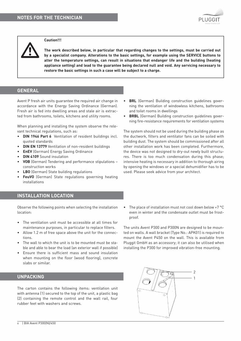
The system should not be used during the building phase asthe ductwork, filters and ventilator fans can be soiled withbuilding dust. The system should be commissioned after allother installation work has been completed. Furthermore,the device was not designed to dry-out newly built structu-res. There is too much condensation during this phase;intensive heating is necessary in addition to thorough airingby opening the windows or a special dehumidifier has to beused. Please seek advice from your architect.
Observe the following points when selecting the installationlocation:
• The ventilation unit must be accessible at all times formaintenance purposes, in particular to replace filters.
• Allow 1.2 m of free space above the unit for the connec-tions.
• The wall to which the unit is to be mounted must be sta-ble and able to bear the load (an exterior wall if possible)
• Ensure there is sufficient mass and sound insulationwhen mounting on the floor (wood flooring), concreteslabs or similar.
• The place of installation must not cool down below +7 °Ceven in winter and the condensate outlet must be frost-proof.
The units Avent P300 and P300N are designed to be moun-ted on walls. A wall bracket (Type No.: APK01) is required tomount the Avent P450 on the wall. This is available fromPluggit GmbH as an accessory; it can also be utilised wheninstalling the P300 for improved vibration-free mounting.
UNPACKING
The carton contains the following items: ventilation unitwith antenna (1) secured to the top of the unit, a plastic bag(2) containing the remote control and the wall rail, four rubber feet with washers and screws.
2
1
7 | BIA Avent P300(N)/450
Immer frische Luft
ASSEMBLY STEPS
1
2
4
3
3 x 140
AP300 (N)
AP450
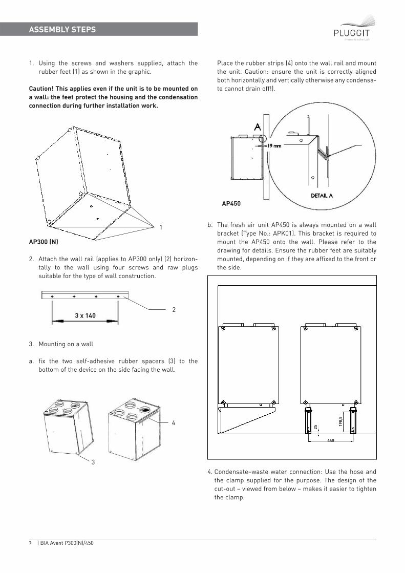
1. Using the screws and washers supplied, attach the rubber feet (1) as shown in the graphic.
Caution! This applies even if the unit is to be mounted ona wall: the feet protect the housing and the condensationconnection during further installation work.
2. Attach the wall rail (applies to AP300 only) (2) horizon-tally to the wall using four screws and raw plugs suitable for the type of wall construction.
3. Mounting on a wall
a. fix the two self-adhesive rubber spacers (3) to the bottom of the device on the side facing the wall.
Place the rubber strips (4) onto the wall rail and mountthe unit. Caution: ensure the unit is correctly alignedboth horizontally and vertically otherwise any condensa-te cannot drain off!).
b. The fresh air unit AP450 is always mounted on a wallbracket (Type No.: APK01). This bracket is required tomount the AP450 onto the wall. Please refer to the drawing for details. Ensure the rubber feet are suitablymounted, depending on if they are affixed to the front orthe side.
4. Condensate–waste water connection: Use the hose andthe clamp supplied for the purpose. The design of thecut-out – viewed from below – makes it easier to tightenthe clamp.
440
198,
5
25
8 | BIA Avent P300(N)/450
Immer frische Luft
ASSEMBLY STEPS
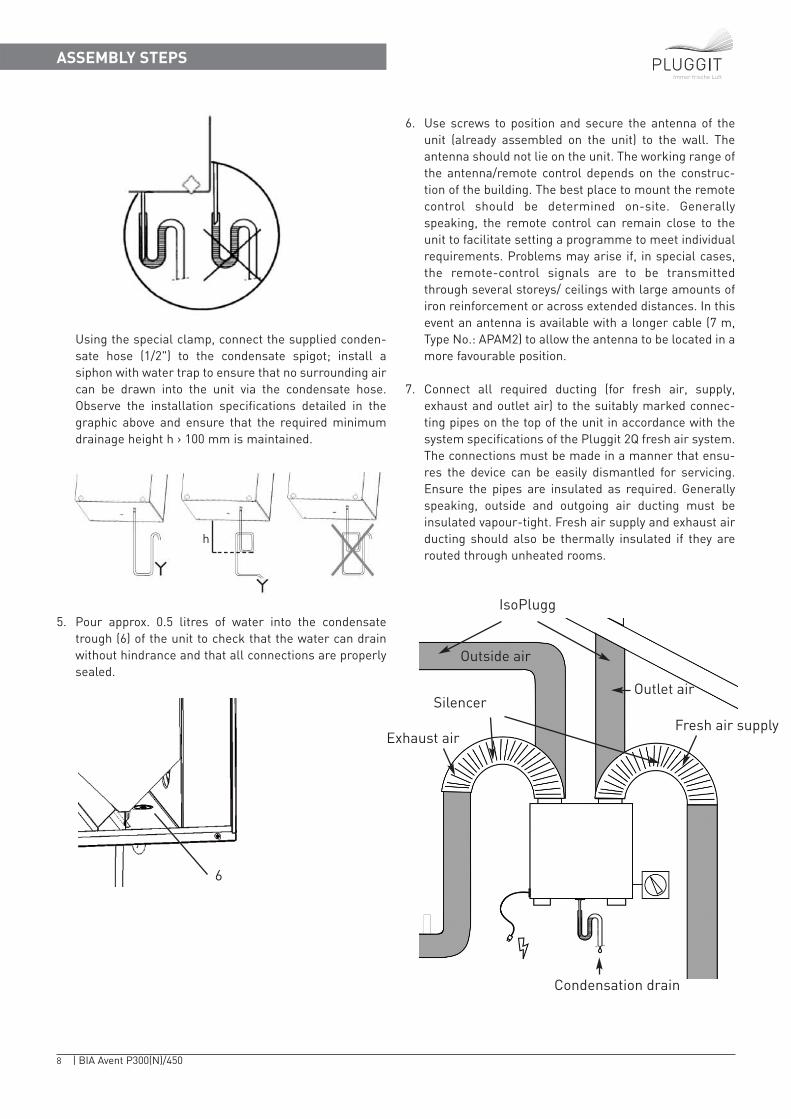
Using the special clamp, connect the supplied conden-sate hose (1/2") to the condensate spigot; install asiphon with water trap to ensure that no surrounding aircan be drawn into the unit via the condensate hose.Observe the installation specifications detailed in thegraphic above and ensure that the required minimumdrainage height h › 100 mm is maintained.
5. Pour approx. 0.5 litres of water into the condensatetrough (6) of the unit to check that the water can drainwithout hindrance and that all connections are properlysealed.
6. Use screws to position and secure the antenna of theunit (already assembled on the unit) to the wall. Theantenna should not lie on the unit. The working range ofthe antenna/remote control depends on the construc-tion of the building. The best place to mount the remotecontrol should be determined on-site. Generally speaking, the remote control can remain close to theunit to facilitate setting a programme to meet individualrequirements. Problems may arise if, in special cases,the remote-control signals are to be transmittedthrough several storeys/ ceilings with large amounts ofiron reinforcement or across extended distances. In thisevent an antenna is available with a longer cable (7 m,Type No.: APAM2) to allow the antenna to be located in amore favourable position.
7. Connect all required ducting (for fresh air, supply,exhaust and outlet air) to the suitably marked connec-ting pipes on the top of the unit in accordance with thesystem specifications of the Pluggit 2Q fresh air system.The connections must be made in a manner that ensu-res the device can be easily dismantled for servicing.Ensure the pipes are insulated as required. Generallyspeaking, outside and outgoing air ducting must beinsulated vapour-tight. Fresh air supply and exhaust airducting should also be thermally insulated if they arerouted through unheated rooms.
IsoPlugg
Outside air
SilencerOutlet air
Fresh air supplyExhaust air
Condensation drain
6
h
9 | BIA Avent P300(N)/450
Immer frische Luft
REMOTE CONTROL SYMBOLS
COMMISSIONING
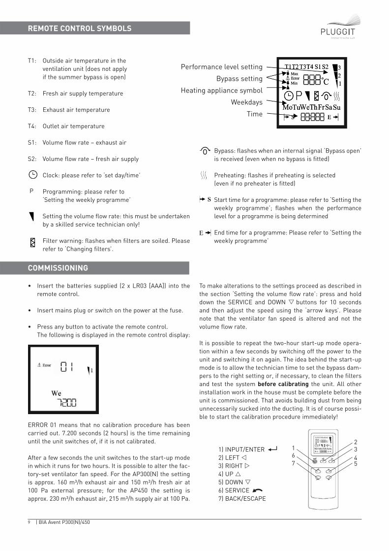
• Insert the batteries supplied (2 x LR03 [AAA]) into theremote control.
• Insert mains plug or switch on the power at the fuse.
• Press any button to activate the remote control. The following is displayed in the remote control display:
ERROR 01 means that no calibration procedure has beencarried out. 7.200 seconds (2 hours) is the time remaininguntil the unit switches of, if it is not calibrated.
After a few seconds the unit switches to the start-up modein which it runs for two hours. It is possible to alter the fac-tory-set ventilator fan speed. For the AP300(N) the settingis approx. 160 m³/h exhaust air and 150 m³/h fresh air at100 Pa external pressure; for the AP450 the setting isapprox. 230 m³/h exhaust air, 215 m³/h supply air at 100 Pa.
To make alterations to the settings proceed as described inthe section ‘Setting the volume flow rate’: press and holddown the SERVICE and DOWN � buttons for 10 secondsand then adjust the speed using the ‘arrow keys’. Pleasenote that the ventilator fan speed is altered and not thevolume flow rate.
It is possible to repeat the two-hour start-up mode opera-tion within a few seconds by switching off the power to theunit and switching it on again. The idea behind the start-upmode is to allow the technician time to set the bypass dam-pers to the right setting or, if necessary, to clean the filtersand test the system before calibrating the unit. All otherinstallation work in the house must be complete before theunit is commissioned. That avoids building dust from beingunnecessarily sucked into the ducting. It is of course possi-ble to start the calibration procedure immediately!
T1: Outside air temperature in the ventilation unit (does not apply if the summer bypass is open)
T2: Fresh air supply temperature
T3: Exhaust air temperature
T4: Outlet air temperature
S1: Volume flow rate – exhaust air
S2: Volume flow rate – fresh air supply
Clock: please refer to ‘set day/time’
P Programming: please refer to ‘Setting the weekly programme’
Setting the volume flow rate: this must be undertakenby a skilled service technician only!
Filter warning: flashes when filters are soiled. Pleaserefer to ‘Changing filters’.
Bypass: flashes when an internal signal ‘Bypass open’is received (even when no bypass is fitted)
Preheating: flashes if preheating is selected (even if no preheater is fitted)
Start time for a programme: please refer to ‘Setting theweekly programme’; flashes when the performancelevel for a programme is being determined
End time for a programme: Please refer to ‘Setting theweekly programme’
Performance level setting
Bypass setting
Heating appliance symbol
Weekdays
Time
234
167 5
1) INPUT/ENTER2) LEFT �3) RIGHT �4) UP �5) DOWN �6) SERVICE7) BACK/ESCAPE
10 | BIA Avent P300(N)/450
Immer frische Luft
Functional principle behind ‘constant volume flow rate control’:
The air at the heat exchanger causes a certain loss of pres-sure, which depends on the volume flow rate. The unit measures this loss of pressure and sets the ventilator fanspeed to achieve the pressure loss that corresponds to theset volume flow rate. This setting is made during the firstcalibration procedure and by the weekly automatic calibration (Mondays at 10.00). To increase control accuracy calibration is always undertaken based on a pressure differential of 50 Pa. The speed required for theset volume flow rate is calculated from the values determined. A frost-protection cycle is initiated if outsi-de temperatures are low (fresh air fan is turned off), tothaw any ice from the heat exchanger.
The ventilator fan speed required to achieve the value 200 m³/h during the first calibration procedure is storedin the unit controls; speeds measured later on are com-pared with this value. If a higher speed is required thenthis is interpreted as an increase in the external loss ofpressure resulting from soiling of the filter. Any decreasein the speed of the exhaust air fan is interpreted as a build-up of ice. Therefore, it is important that no changesare made to the system following the first calibration procedure that may alter the system pressure or that anew fist calibration procedure is undertaken followingany such alteration to the system, such as replacing thefilters (including in the exhaust air extractors, geother-mal heat exchangers and so forth).
CALIBRATION
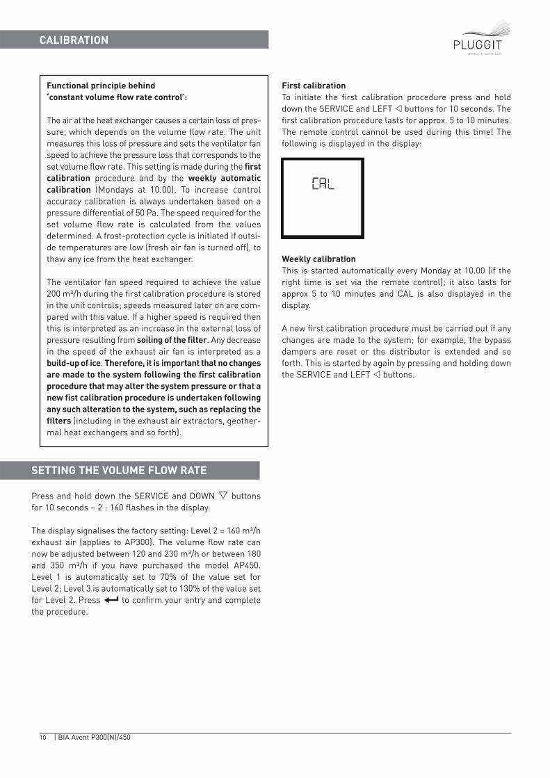
First calibrationTo initiate the first calibration procedure press and holddown the SERVICE and LEFT � buttons for 10 seconds. Thefirst calibration procedure lasts for approx. 5 to 10 minutes.The remote control cannot be used during this time! Thefollowing is displayed in the display:
Weekly calibrationThis is started automatically every Monday at 10.00 (if theright time is set via the remote control); it also lasts forapprox 5 to 10 minutes and CAL is also displayed in thedisplay.
A new first calibration procedure must be carried out if anychanges are made to the system; for example, the bypassdampers are reset or the distributor is extended and soforth. This is started by again by pressing and holding downthe SERVICE and LEFT � buttons.
SETTING THE VOLUME FLOW RATE
Press and hold down the SERVICE and DOWN � buttonsfor 10 seconds – 2 : 160 flashes in the display.
The display signalises the factory setting: Level 2 = 160 m³/hexhaust air (applies to AP300). The volume flow rate cannow be adjusted between 120 and 230 m³/h or between 180and 350 m³/h if you have purchased the model AP450. Level 1 is automatically set to 70% of the value set for Level 2; Level 3 is automatically set to 130% of the value setfor Level 2. Press to confirm your entry and completethe procedure.
11 | BIA Avent P300(N)/450
Immer frische Luft
VIEWING PARAMETER AND FACTORY SETTINGS
Altering the ventilation levelsPress the UP and DOWN � /� buttons to toggle manuallybetween the Levels Off, 1, 2 and 3. The standard setting isLevel 2.
The set speed increment is indicated by the bar graph on the top of the display:
Viewing temperatures, the volume of air and the ventilator fan speed
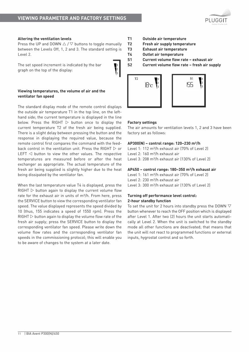
The standard display mode of the remote control displaysthe outside air temperature T1 in the top line, on the left-hand side; the current temperature is displayed in the linebelow. Press the RIGHT � button once to display the current temperature T2 of the fresh air being supplied.There is a slight delay between pressing the button and theresponse in displaying the required value, because theremote control first compares the command with the feed-back control in the ventilation unit. Press the RIGHT � orLEFT � button to view the other values. The respectivetemperatures are measured before or after the heatexchanger as appropriate. The actual temperature of thefresh air being supplied is slightly higher due to the heatbeing dissipated by the ventilator fan.
When the last temperature value T4 is displayed, press theRIGHT � button again to display the current volume flowrate for the exhaust air in units of m³/h. From here, pressthe SERVICE button to view the corresponding ventilator fanspeed. The value displayed represents the speed divided by10 (thus, 155 indicates a speed of 1550 rpm). Press theRIGHT � button again to display the volume flow rate of thefresh air supply; press the SERVICE button to display the corresponding ventilator fan speed. Please write down thevolume flow rates and the corresponding ventilator fanspeeds in the commissioning protocol; this will enable youto be aware of changes to the system at a later date.
T1 Outside air temperatureT2 Fresh air supply temperatureT3 Exhaust air temperatureT4 Outlet air temperatureS1 Current volume flow rate – exhaust airS2 Current volume flow rate – fresh air supply
Factory settingsThe air amounts for ventilation levels 1, 2 and 3 have beenfactory set as follows:
AP300(N) – control range: 120–230 m³/hLevel 1: 112 m³/h exhaust air (70% of Level 2) Level 2: 160 m³/h exhaust airLevel 3: 208 m³/h exhaust air (130% of Level 2)
AP450 – control range: 180–350 m³/h exhaust airLevel 1: 161 m³/h exhaust air (70% of Level 2) Level 2: 230 m³/h exhaust airLevel 3: 300 m³/h exhaust air (130% of Level 2)
Turning off performance level control: 2-hour standby functionTo set the unit for 2 hours into standby press the DOWN �button whenever to reach the OFF position which is displayedafter Level 1. After two (2) hours the unit starts automati-cally at Level 2. When the unit is switched to the standbymode all other functions are deactivated; that means thatthe unit will not react to programmed functions or externalinputs, hygrostat control and so forth.
12 | BIA Avent P300(N)/450
Immer frische Luft
Wochenprogramm einstellenSETTING THE WEEKLY PROGRAMME
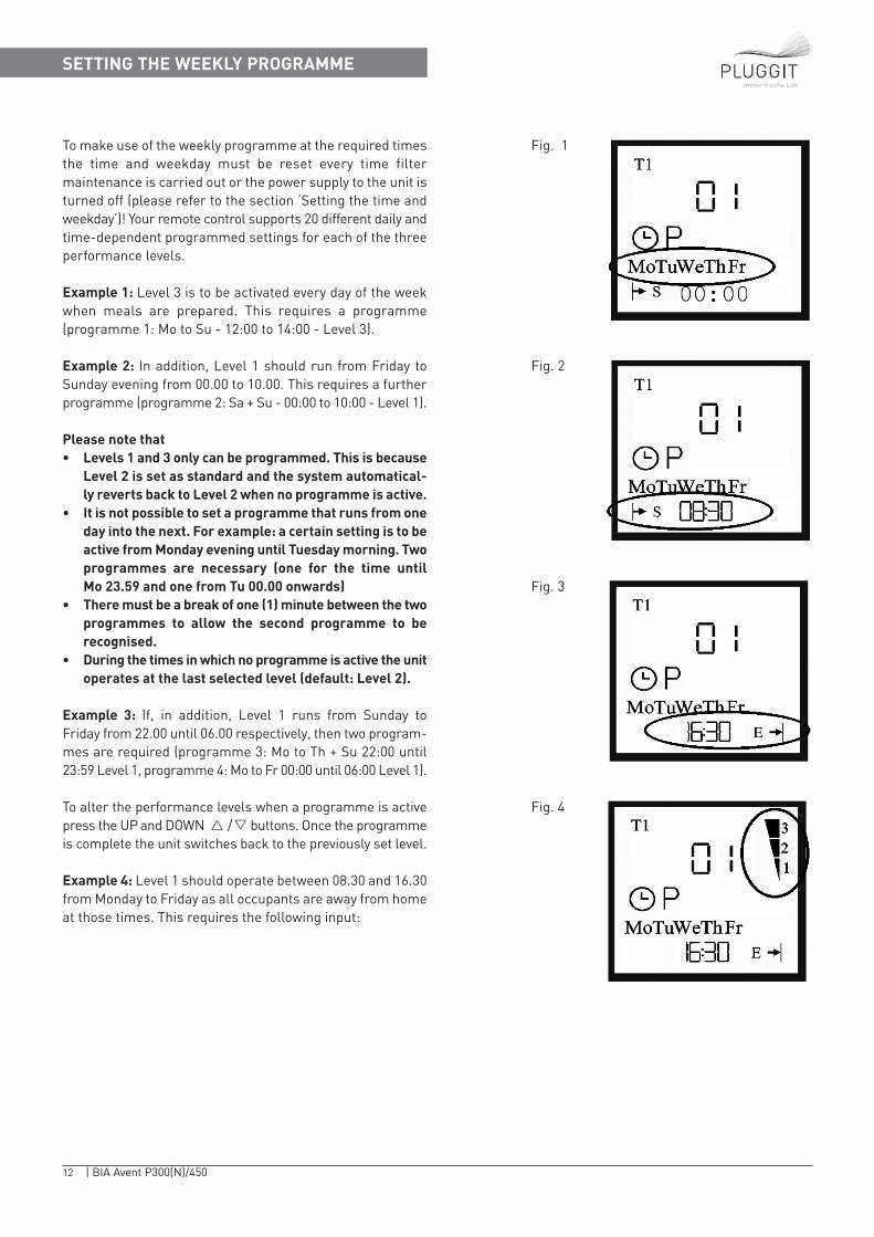
To make use of the weekly programme at the required timesthe time and weekday must be reset every time filter maintenance is carried out or the power supply to the unit isturned off (please refer to the section ‘Setting the time andweekday’)! Your remote control supports 20 different daily andtime-dependent programmed settings for each of the threeperformance levels.
Example 1: Level 3 is to be activated every day of the weekwhen meals are prepared. This requires a programme (programme 1: Mo to Su - 12:00 to 14:00 - Level 3).
Example 2: In addition, Level 1 should run from Friday to Sunday evening from 00.00 to 10.00. This requires a furtherprogramme (programme 2: Sa + Su - 00:00 to 10:00 - Level 1).
Please note that • Levels 1 and 3 only can be programmed. This is because
Level 2 is set as standard and the system automatical-ly reverts back to Level 2 when no programme is active.
• It is not possible to set a programme that runs from oneday into the next. For example: a certain setting is to beactive from Monday evening until Tuesday morning. Twoprogrammes are necessary (one for the time until Mo 23.59 and one from Tu 00.00 onwards)
• There must be a break of one (1) minute between the twoprogrammes to allow the second programme to be recognised.
• During the times in which no programme is active the unitoperates at the last selected level (default: Level 2).
Example 3: If, in addition, Level 1 runs from Sunday to Friday from 22.00 until 06.00 respectively, then two program-mes are required (programme 3: Mo to Th + Su 22:00 until23:59 Level 1, programme 4: Mo to Fr 00:00 until 06:00 Level 1).
To alter the performance levels when a programme is activepress the UP and DOWN � /� buttons. Once the programmeis complete the unit switches back to the previously set level.
Example 4: Level 1 should operate between 08.30 and 16.30from Monday to Friday as all occupants are away from homeat those times. This requires the following input:
Fig. 1
Fig. 2
Fig. 3
Fig. 4
13 | BIA Avent P300(N)/450
Immer frische Luft
SETTING THE WEEKLY PROGRAMME
1. Activate the remote control (Press any button)
2. Press ENTER (Clock symbol flashes)
3. Press the RIGHT � button (P flashes in the display)
4. Press ENTER (01 flashes in the display)
5. Using the RIGHT � button, another if necessary select programme number X (0X flashes in the display)
6. Press the ENTER button to confirm (Mo flashes in the display)
7. If desired, press the UP � button to activate the day (Mo lights continually, Tu flashes in the display)
8. If you do not want the programme to apply to that day press (Tu flashes in the display)the RIGHT � button to move to the next day
9. Repeat steps 7 and 8 until all the desired days are activated(Mo to Fr) – (please refer to Fig. 1) To deactivate selected days press the DOWN� button!
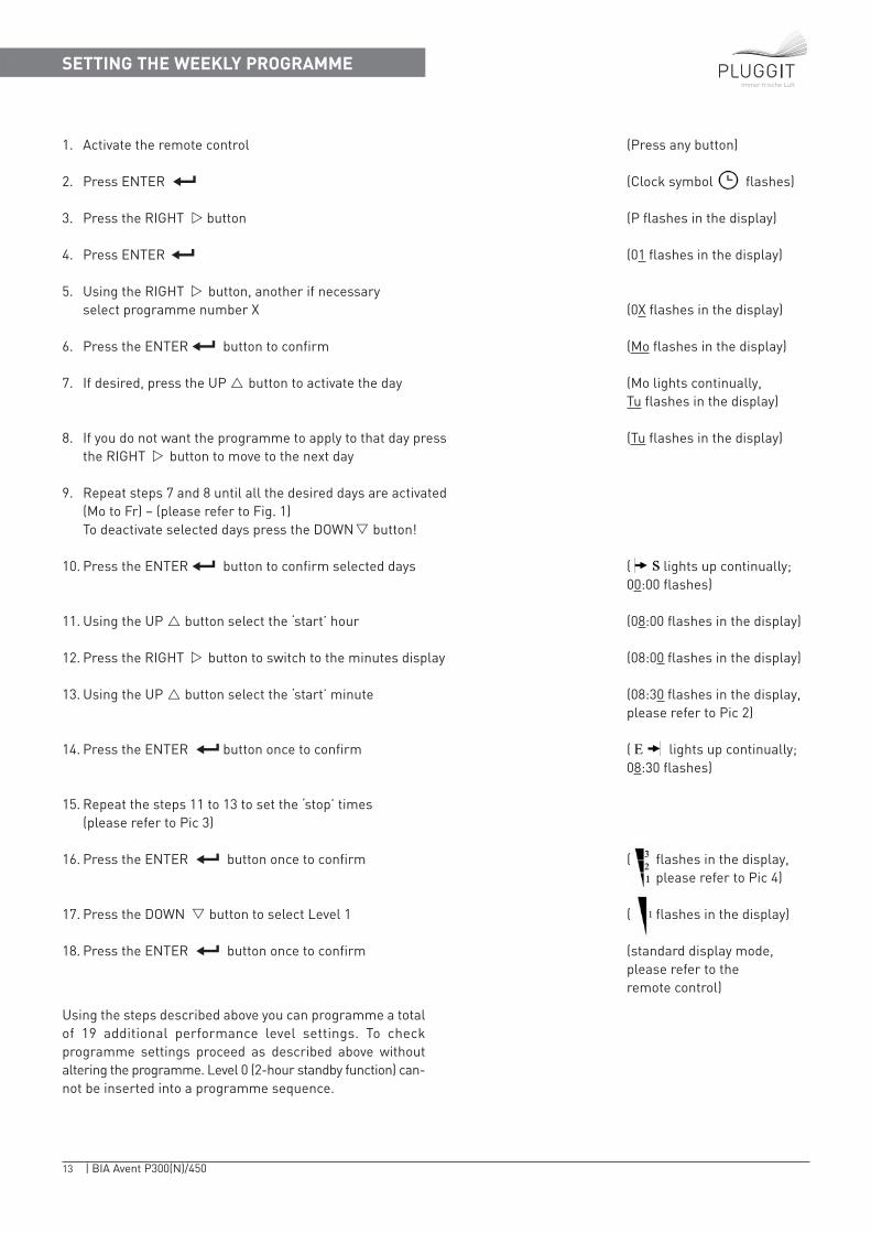
10. Press the ENTER button to confirm selected days ( lights up continually; 00:00 flashes)
11. Using the UP � button select the ‘start’ hour (08:00 flashes in the display)
12. Press the RIGHT � button to switch to the minutes display (08:00 flashes in the display)
13. Using the UP � button select the ‘start’ minute (08:30 flashes in the display, please refer to Pic 2)
14. Press the ENTER button once to confirm ( lights up continually; 08:30 flashes)
15. Repeat the steps 11 to 13 to set the ‘stop’ times(please refer to Pic 3)
16. Press the ENTER button once to confirm ( flashes in the display, please refer to Pic 4)
17. Press the DOWN � button to select Level 1 ( flashes in the display)
18. Press the ENTER button once to confirm (standard display mode, please refer to theremote control)
Using the steps described above you can programme a totalof 19 additional performance level settings. To check programme settings proceed as described above without altering the programme. Level 0 (2-hour standby function) can-not be inserted into a programme sequence.
14 | BIA Avent P300(N)/450
Immer frische Luft
DELETING A WEEKLY PROGRAMME
Proceed as follows to delete wrong or outdated programmes:
1. Activate the remote control (Press any button)
2. Press the ENTER button once (Clock symbol flashes)
3. Press the RIGHT � button once (P flashes in the display)
4. Press the ENTER button once (P and 01 flash in the display)
5. Using the UP � button select programme number X (0X flashes in the display)
6. Press and hold down the SERVICE button until the display reverts to standard display mode (please refer to ‘Remote control’). E is displayed for a short period of time
CHANGING FILTERS / MAINTENANCE
REPLACING FILTERS
The outside and exhaust air is cleaned via one or several filters. These must be checked regularly to keep the air andthe ducting clean as well as to ensure the system operatesquietly. Depending on the level of contamination of the out-side air cleaning or replacing the filter(s) can become necessary just two weeks after commissioning (for exampledue to heavy building-site dust levels in new development areas) or after six months. You can determine if it is necessary to clean or replace the filter(s) if the noise level ofthe ventilator fans in the unit increases, by visually checkingthe filter(s) or when the filter symbol on the remote controlflashes.
If you fail to notice the flashing filter symbol on the remotecontrol and the filters becomes increasingly clogged up theunit will automatically shut down and ERROR 02 will be displayed.
The filter(s) must now be cleaned or replaced to allow the unitto function flawlessly. The remote control will then auto-matically revert to the standard display mode.
We recommend:Check the ventilation unit carefully once a year (for examplein spring) independent of the filter alarm function and, if necessary, clean the unit and replace all filters.The air ducting, particularly the air supply ducts should bechecked every 10 years and cleaned, if necessary. If you wish to fit different types of filters than previously fitted (for example fine filters instead of the standard G4 filters) the unit must be recalibrated to allow it to be optimallyadapted to the new system conditions. The calibration procedure should be carried out by an authorised specialistcompany.
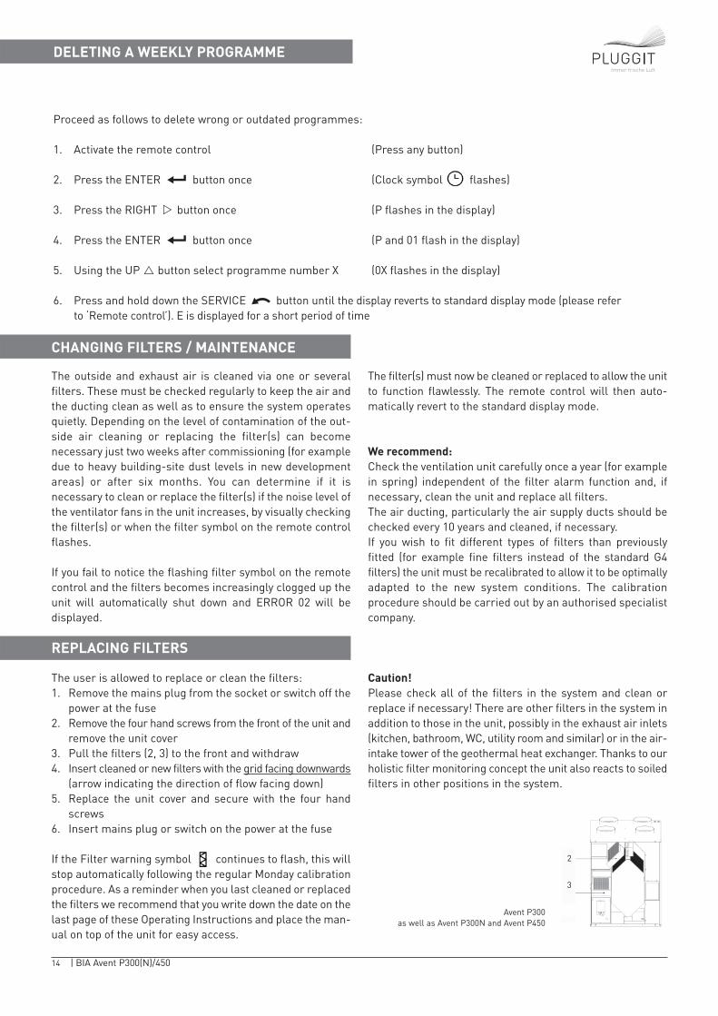
The user is allowed to replace or clean the filters:1. Remove the mains plug from the socket or switch off the
power at the fuse2. Remove the four hand screws from the front of the unit and
remove the unit cover3. Pull the filters (2, 3) to the front and withdraw4. Insert cleaned or new filters with the grid facing downwards
(arrow indicating the direction of flow facing down)5. Replace the unit cover and secure with the four hand
screws6. Insert mains plug or switch on the power at the fuse
If the Filter warning symbol continues to flash, this willstop automatically following the regular Monday calibrationprocedure. As a reminder when you last cleaned or replacedthe filters we recommend that you write down the date on thelast page of these Operating Instructions and place the man-ual on top of the unit for easy access.
Caution!Please check all of the filters in the system and clean or replace if necessary! There are other filters in the system inaddition to those in the unit, possibly in the exhaust air inlets(kitchen, bathroom, WC, utility room and similar) or in the air-intake tower of the geothermal heat exchanger. Thanks to ourholistic filter monitoring concept the unit also reacts to soiledfilters in other positions in the system.
Avent P300as well as Avent P300N and Avent P450
2
3
15 | BIA Avent P300(N)/450
Immer frische Luft
FROST PROTECTION
Proceed as follows to alter the maximum and minimum temperatures:Example: alter T Max to 22 °C; alter T Min to 14 °C
1. Press any button to activate the remote control
2. Press the button 1 x ( flashes in the display)
3. Press the RIGHT � button 3 x ( flashes in the display)
4. Press the button 1 x (displays Max; 24 °C)
5. Press the DOWN � button 2 x (displays Max; 22 °C)
6. To confirm, press the button 1 x (displays Min; 13 °C)
7. Press the UP � button 1 x (displays Min; 14 °C)
8. To confirm, press the button 1 x (display reverts to standard display mode)
SETTING THE SUMMER BYPASS
Moisture in the exhaust air condenses in the heat exchanger.To prevent the heat exchanger freezing up the fresh air fanis restricted and turned off for a short period if the temper-ature of the outlet air falls below +2 °C (outside air temper-ature below -6 °C). This ensures that no further cold air is fedinto the system and allows the exhaust air to thaw the heatexchanger.
The pressure monitoring system senses if the heat exchanger does freeze up under extreme conditions, and a longer frost protection cycle is initiated.
The summer bypass is a part of the ventilation units Avent P300and P450. It can be optionally retrofitted to the Avent P300N(Type No.: APSS3)! The summer bypass set for retrofitting con-sists of a damper flap and a servomotor.
The bypass circuits are always active, even when no bypassis fitted. The bypass opens if the following three conditions arefulfilled:
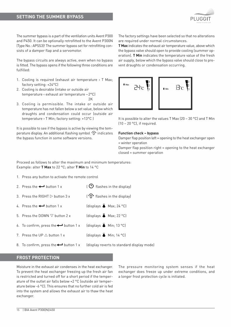
1. Cooling is required (exhaust air temperature › T Max; factory setting: +24°C)
2. Cooling is desirable (intake or outside air temperature ‹ exhaust air temperature −2°C)
2K3. Cooling is permissible. The intake or outside air
temperature has not fallen below a set value, below whichdraughts and condensation could occur (outside air temperature › T Min; factory setting: +13°C )
It is possible to see if the bypass is active by viewing the tem-perature display. An additional flashing symbol indicatesthe bypass function in some software versions.
The factory settings have been selected so that no alterationsare required under normal circumstances. T Max indicates the exhaust air temperature value, above whichthe bypass valve should open to provide cooling (summer op-eration). T Min indicates the temperature value of the freshair supply, below which the bypass valve should close to pre-vent draughts or condensation occurring.
It is possible to alter the values T Max (20 – 30 °C) and T Min(10 – 20 °C), if required.
Function check – bypassDamper flap position left = opening to the heat exchanger open= winter operationDamper flap position right = opening to the heat exchangerclosed = summer operation
The optional, external preheating device prevents the exhaustair from cooling below frost protection levels, which in turnprevents condensing moisture from freezing. The devicestarts up when the device would normally enter a frost-pro-tection cycle triggered by internal temperature monitoring.That ensures the system is operated economically.
Without the preheating device or preheating via a geother-mal heat exchanger the frost-protection circuit integratedin the device would restrict the supply of cold fresh air. Thisrestriction of supply air results in an imbalance in the volu-me flow rates when outside temperatures are very low andleads to underpressure in the building.
16 | BIA Avent P300(N)/450
Immer frische Luft
COMBINED USE WITH HEATING APPLIANCES
If a non room-sealed solid-fuel heating appliance or similarheating system is installed there is a danger that the under-pressure generated in the building by the ventilation systemcan lead to flue gas escaping. The following measures canbe taken to prevent this happening:
1. Use of a room-sealed heating appliance (with DIBTapproval (German)).
2. Automatic shut-down of the ventilation system when theheating appliance is being operated (alternating operationin particular when an open fireplace is seldom in use).
3. Installation of monitoring equipment to monitor theextraction of exhaust gas (monitoring of underpressure).The ventilation unit is switched off should the extractionequipment malfunction.
4. Individual solution following consultation with a qualifiedengineer.
In each case the combustion air to the heating applianceshould be fed from outside through a separate duct and theventilation unit should be fitted with a preheater (geother-mal heat exchanger or electric heating device). Without thispreheating facility and assuming a constant volume flowrate of exhaust air the supply of cold air to the ventilationunit (meaning the supply of outside air) would have to berestricted to protect the heat exchanger from frost, which inturn would result in underpressure. In addition, you canalter the heating appliance setting of Avent P ventilationunits from No (0 – factory setting) to Yes (1). Should the preheating device fail or some boundary conditions areunder-dimensioned the ventilation unit is shut down completely for four hours, instead of the usual frost protection cycle, when the heating appliance setting is activated.
Proceed as follows to alter the settings:
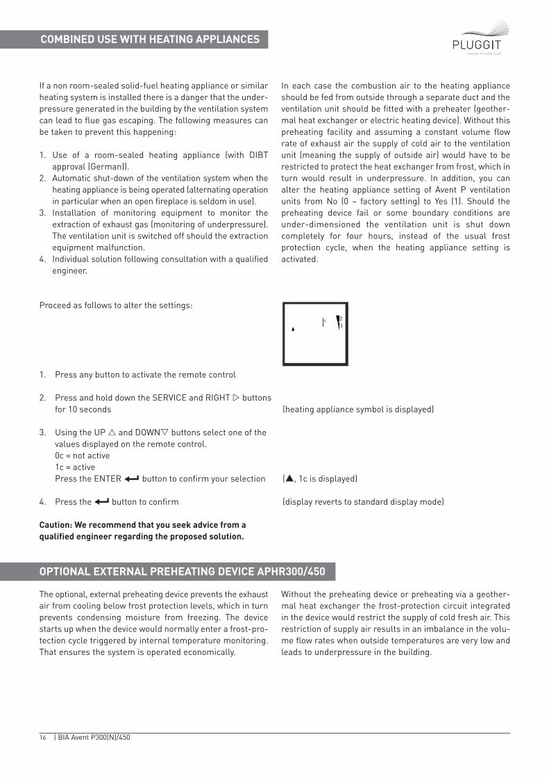
1. Press any button to activate the remote control
2. Press and hold down the SERVICE and RIGHT � buttons for 10 seconds (heating appliance symbol is displayed)
3. Using the UP � and DOWN� buttons select one of the values displayed on the remote control.0c = not active1c = activePress the ENTER button to confirm your selection (▲, 1c is displayed)
4. Press the button to confirm (display reverts to standard display mode)
Caution: We recommend that you seek advice from a qualified engineer regarding the proposed solution.
OPTIONAL EXTERNAL PREHEATING DEVICE APHR300/450
17 | BIA Avent P300(N)/450
OPTIONAL EXTERNAL POST HEATING DEVICE
OPTIONAL HUMIDITY SENSOR/HYGROSTAT
Immer frische Luft
External post heating devices with integrated controls aresometimes used to heat a passive house via the fresh air supply. To prevent any hot water coil solution from freezingand also to prevent condensation from forming on the outsideof the fresh-air supply ducting in the event of a malfunctionthe ventilation unit is switched off for 60 minutes if the
temperature of the fresh air being supplied falls below +6 °C;ERROR 08 is displayed. After this time has elapsed the unitperforms a two-minute test to determine the temperature.Please note that the postheating device is not the same typeas the Pluggit frost protection preheating device APHR300/450.
Pluggit GmbH offers a humidity sensor (Type No.: APFS1) asan accessory. This can be utilised to set the fresh air unit toLevel 3 when humidity levels are high (recommended setting:winter › 60%, summer › 80%), for example to dehumidify theair in the bathroom or in winter to set the ventilation unit toLevel 1 to retain humidity levels, for example in the living room,when humidity levels are low (‹ 30%). The device automati-cally switches to the previously set level when humidity levels fall below or exceed the set humidity limit.The hygrostat (potential-free switch) is connected to the mainPCB module of the unit by means of the ‘cable harness for additional functions’ (Type No.: APKB1).
The hygrostat user manual describes three (3) positions:L = supply phase = 12 V Pin No. 3 (green)E = dehumidification = Pin No. 4 (yellow) (= Level III)B = alternative humidification
That means either dehumidification or humidification mustbe chosen. Under normal circumstances 'dehumidification'is selected. The following termination is required for the po-sition ‘humidification’. L = supply phase = 12 V Pin No.1 (white)B = humidification = Pin No. 2 (brown) (= Level I)
OPTIONAL EXTERNAL CONTROLLER (3-STAGE SWITCH, BUS)
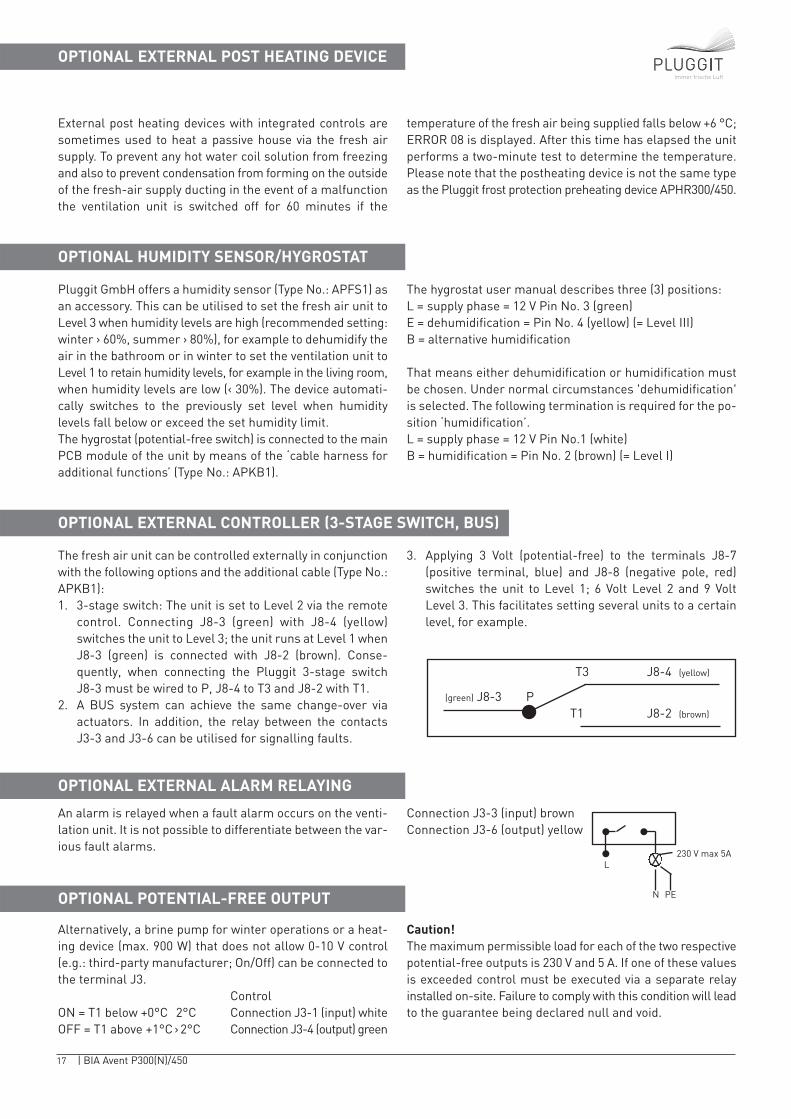
The fresh air unit can be controlled externally in conjunctionwith the following options and the additional cable (Type No.:APKB1): 1. 3-stage switch: The unit is set to Level 2 via the remote
control. Connecting J8-3 (green) with J8-4 (yellow) switches the unit to Level 3; the unit runs at Level 1 whenJ8-3 (green) is connected with J8-2 (brown). Conse-quently, when connecting the Pluggit 3-stage switch J8-3 must be wired to P, J8-4 to T3 and J8-2 with T1.
2. A BUS system can achieve the same change-over via actuators. In addition, the relay between the contacts J3-3 and J3-6 can be utilised for signalling faults.
3. Applying 3 Volt (potential-free) to the terminals J8-7 (positive terminal, blue) and J8-8 (negative pole, red)switches the unit to Level 1; 6 Volt Level 2 and 9 Volt Level 3. This facilitates setting several units to a certainlevel, for example.
OPTIONAL EXTERNAL ALARM RELAYING
An alarm is relayed when a fault alarm occurs on the venti-lation unit. It is not possible to differentiate between the var-ious fault alarms.
Connection J3-3 (input) brownConnection J3-6 (output) yellow
OPTIONAL POTENTIAL-FREE OUTPUT
Alternatively, a brine pump for winter operations or a heat-ing device (max. 900 W) that does not allow 0-10 V control (e.g.: third-party manufacturer; On/Off) can be connected tothe terminal J3.
ControlON = T1 below +0°C 2°C Connection J3-1 (input) whiteOFF = T1 above +1°C › 2°C Connection J3-4 (output) green
Caution!The maximum permissible load for each of the two respectivepotential-free outputs is 230 V and 5 A. If one of these valuesis exceeded control must be executed via a separate relay installed on-site. Failure to comply with this condition will leadto the guarantee being declared null and void.
L
N PE
230 V max 5AX
J8-3
J8-4
J8-2
T3
T1P(green)
(yellow)
(brown)
18 | BIA Avent P300(N)/450
Immer frische Luft
ADDITIONAL REMOTE CONTROL
An additional remote control can be utilised to meet specialrequirements; a new remote control may be required incase of loss or damage. This is set on-site so that it can only
communicate with the PCB of a single ventilation unit. Oncethis connection has been created the remote control cannotbe utilised in conjunction with any other PCB.
PRIORITIES
Control commands for the ventilation unit are prioritised asfollows:
1. Hygrostat Level 32. Hygrostat Level 13. 3-9 V control switching4. Manual5. Programme
Example: If Level 1 is actuated via a hygrostat (alternativelya 3-stage switch or a BUS controller at the same terminal)it is not possible to alter the level manually. If at the sametime a signal is received from the bathroom requestingLevel 3 to dehumidify the bathroom then Level 3 is actuated.
CLEANING AND REPLACING THE HEAT EXCHANGER
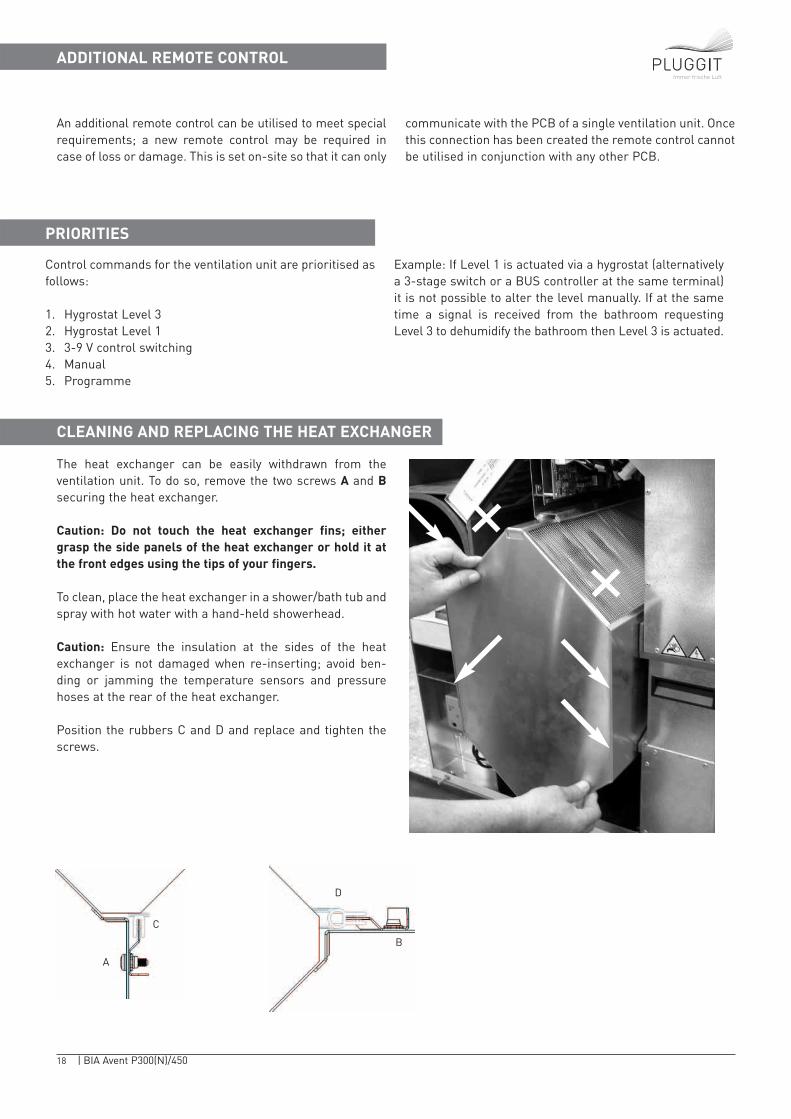
The heat exchanger can be easily withdrawn from the ventilation unit. To do so, remove the two screws A and Bsecuring the heat exchanger.
Caution: Do not touch the heat exchanger fins; eithergrasp the side panels of the heat exchanger or hold it atthe front edges using the tips of your fingers.
To clean, place the heat exchanger in a shower/bath tub andspray with hot water with a hand-held showerhead.
Caution: Ensure the insulation at the sides of the heatexchanger is not damaged when re-inserting; avoid ben-ding or jamming the temperature sensors and pressurehoses at the rear of the heat exchanger.
Position the rubbers C and D and replace and tighten thescrews.
A
C
D
B
19 | BIA Avent P300(N)/450
Immer frische Luft
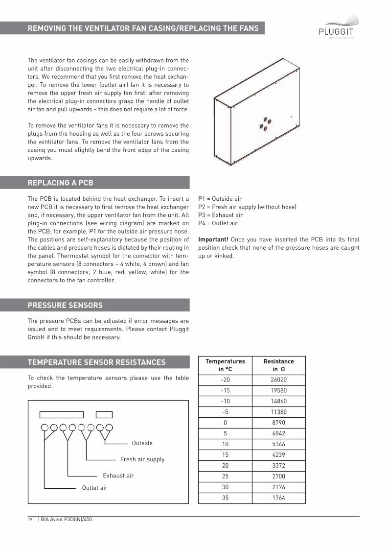
REMOVING THE VENTILATOR FAN CASING/REPLACING THE FANS
The ventilator fan casings can be easily withdrawn from theunit after disconnecting the two electrical plug-in connec-tors. We recommend that you first remove the heat exchan-ger. To remove the lower (outlet air) fan it is necessary toremove the upper fresh air supply fan first; after removingthe electrical plug-in connectors grasp the handle of outletair fan and pull upwards – this does not require a lot of force.
To remove the ventilator fans it is necessary to remove theplugs from the housing as well as the four screws securingthe ventilator fans. To remove the ventilator fans from thecasing you must slightly bend the front edge of the casingupwards.
REPLACING A PCB
The PCB is located behind the heat exchanger. To insert anew PCB it is necessary to first remove the heat exchangerand, if necessary, the upper ventilator fan from the unit. Allplug-in connections (see wiring diagram) are marked onthe PCB; for example, P1 for the outside air pressure hose.The positions are self-explanatory because the position ofthe cables and pressure hoses is dictated by their routing inthe panel. Thermostat symbol for the connector with tem-perature sensors (8 connectors – 4 white, 4 brown) and fansymbol (8 connectors; 2 blue, red, yellow, white) for theconnectors to the fan controller.
P1 = Outside airP2 = Fresh air supply (without hose)P3 = Exhaust airP4 = Outlet air
Important! Once you have inserted the PCB into its finalposition check that none of the pressure hoses are caughtup or kinked.
PRESSURE SENSORS
The pressure PCBs can be adjusted if error messages areissued and to meet requirements. Please contact PluggitGmbH if this should be necessary.
TEMPERATURE SENSOR RESISTANCES
To check the temperature sensors please use the table provided.
Outside
Fresh air supply
Exhaust air
Outlet air
Temperatures in °C
Resistance in Ω
-20 26020
-15 19580
-10 14860
-5 11380
0 8790
5 6842
10 5366
15 4239
20 3372
25 2700
30 2176
35 1764

20 | BIA Avent P300(N)/450
Immer frische Luft
FAULT ALARMS/ERROR CODES
Faults or defects are displayed on your remote control by means of error codes; for example, ERROR 03. Please notethe error codes simplifiy troubleshooting procedures. Errormessages can also be indicated optically or visually (please refer to ‘Changing filters).
The error message can be reset by briefly disconnecting theventilation unit from the power supply or opening the front panel.
If there is a malfunction in the remote control this can be restarted by briefly removing and reinserting the batteries. ThePCB can also be reset to the original factory settings.
Please contact Pluggit GmbH if thisshould be necessary.
Display Error Cause Remedy
ERROR 01 No calibration Not yet commissioned Calibrate unit
ERROR 02 Bypass damper does not closeduring calibration
The remote control issues thecode ERROR 02 if the ventilatorfans rotate faster than 2500rpm to obtain 35 Pa during thesecond (Low Point Calibration)‘first calibration procedure’.Generally, the reason is thesystem pressure in the ductingis too high
The unit will shut down due tosoiled filters or changes madeto the system after the firstcalibration
Error displayed as (filtersymbol). Light soiling influenced by wind load at thefilter during the calibration process. Allow a week to passbefore the next calibration
ERROR 04 causes ERROR 02 tobe issued. Pressure PCB deviation or damaged in transport
Check ducting. Check bypass.Clean or replace filters (alsooutside of unit). If necessary,carry out first calibration procedure after replacing allinternal and external filters
Adjust pressure plate
ERROR 03 Fault temperature sensor (sym-bol T1, T2, T3 or T4 flashes)
Cable break in temperaturesensor
Check plug connection of tem-perature sensor on the PCBreplace sensor if necessary
ERROR 04 Fault pressure sensor Kink in hose; pressure sensordefective or requires adjusting
Check hose routing. Replacehose or the main PCB module ifnecessary. Adjust pressure sen-sor
21 | BIA Avent P300(N)/450
Immer frische Luft
FAULT ALARMS/ERROR CODES
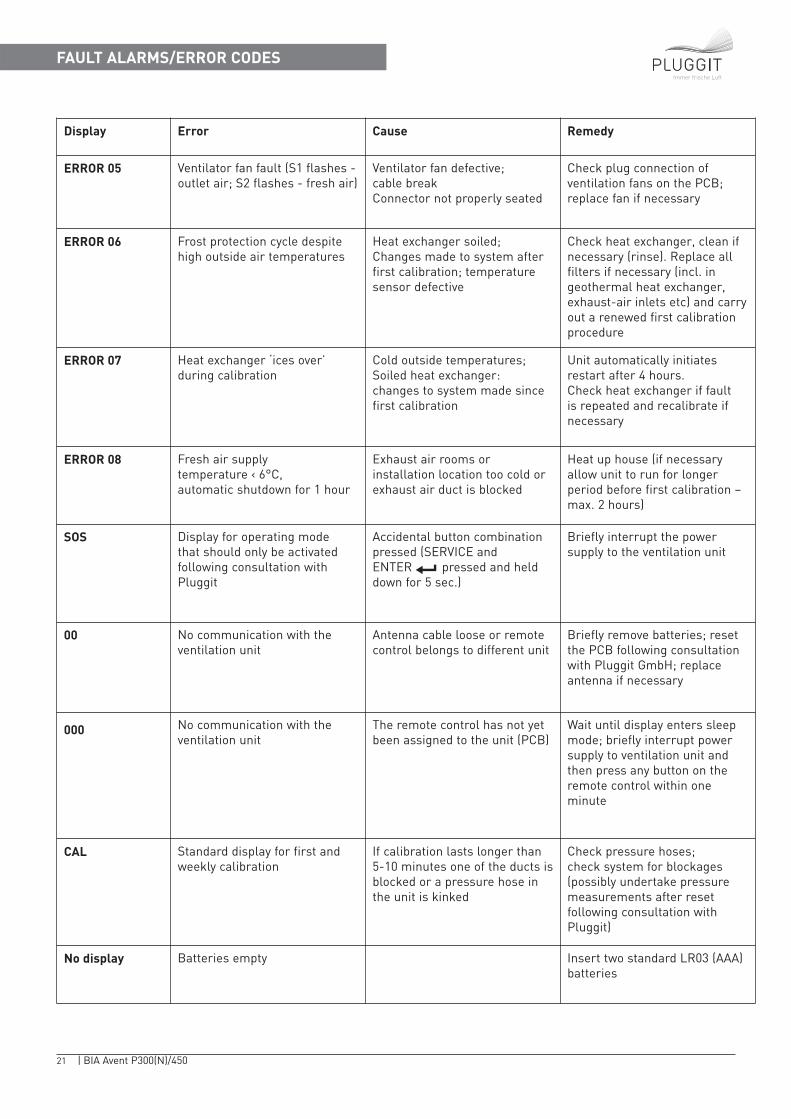
Display Error Cause Remedy
ERROR 05 Ventilator fan fault (S1 flashes -outlet air; S2 flashes - fresh air)
Ventilator fan defective; cable breakConnector not properly seated
Check plug connection of ventilation fans on the PCB;replace fan if necessary
ERROR 06 Frost protection cycle despitehigh outside air temperatures
Heat exchanger soiled; Changes made to system afterfirst calibration; temperaturesensor defective
Check heat exchanger, clean ifnecessary (rinse). Replace allfilters if necessary (incl. in geothermal heat exchanger,exhaust-air inlets etc) and carryout a renewed first calibrationprocedure
ERROR 07 Heat exchanger ‘ices over’during calibration
Cold outside temperatures; Soiled heat exchanger:changes to system made sincefirst calibration
Unit automatically initiatesrestart after 4 hours. Check heat exchanger if fault is repeated and recalibrate ifnecessary
ERROR 08 Fresh air supplytemperature ‹ 6°C, automatic shutdown for 1 hour
Exhaust air rooms or installation location too cold orexhaust air duct is blocked
Heat up house (if necessaryallow unit to run for longerperiod before first calibration –max. 2 hours)
SOS Display for operating mode that should only be activatedfollowing consultation withPluggit
Accidental button combinationpressed (SERVICE and ENTER pressed and helddown for 5 sec.)
Briefly interrupt the power supply to the ventilation unit
00 No communication with theventilation unit
Antenna cable loose or remotecontrol belongs to different unit
Briefly remove batteries; resetthe PCB following consultationwith Pluggit GmbH; replaceantenna if necessary
000 No communication with theventilation unit
The remote control has not yetbeen assigned to the unit (PCB)
Wait until display enters sleepmode; briefly interrupt powersupply to ventilation unit andthen press any button on theremote control within oneminute
CAL Standard display for first andweekly calibration
If calibration lasts longer than5-10 minutes one of the ducts isblocked or a pressure hose inthe unit is kinked
Check pressure hoses; check system for blockages (possibly undertake pressuremeasurements after reset following consultation withPluggit)
No display Batteries empty Insert two standard LR03 (AAA)batteries
22 | BIA Avent P300(N)/450
Immer frische Luft
FAULT ALARMS/ERROR CODES
ERROR CORRECTION – Test ModeERROR 01ERROR 01 is displayed during test operations and meansthat the unit has not yet been calibrated. To rectify the error,initiate the calibration procedure (please refer to Chapter‘Calibration’).
ERROR CORRECTION – Filter BlockagesERROR 02The unit will shut down and ERROR 02 is displayed if the filters are not cleaned or replaced and continue to be soiledeven further despite the ‘Filter warning’ symbol beingdisplayed. To rectify the error, clean or replace the filters(please refer to the Chapter ‘Changing filters’). This canalso be displayed if changes are made to the pressurebalance of the system after the first calibration procedurehas been carried out (flap settings and so forth). In such anevent all filters (including in the geothermal heat exchanger,exhaust air extractors and so forth) must be cleaned orreplaced and a new first calibration procedure carried out.
ERROR CORRECTION – Temperature SensorERROR 03The symbol for a temperature sensor flashes if it is notfunctioning, has been short-circuited or is not available.ERROR 03 is displayed. To rectify the error, check the plugconnections (please refer to the wiring diagram) or calltechnical service to replace the sensor in question.
ERROR CORRECTION – Pressure SensorERROR 04To avoid undesirable pressure imbalances and prevent therisk of frost damage the ventilation unit shuts down if oneof the pressure sensors is defective or a pressure hose iskinked or damaged. ERROR 04 is displayed. It is possible toinitiate a restart by briefly interrupting the power supply tothe ventilation unit. To rectify the error, check the pressurehoses, adjust or replace the pressure sensors or replacethe main PCB module (main board and pressure PCB).
Caution! It is necessary to recalibrate and set the volumeflow rate after replacing the main PCB module! When carrying out a recalibration ensure that all filters (inclu-ding those in the system outside of the unit) are clean or,even better, new.
ERROR CORRECTION – Ventilator Fan FaultERROR 05To avoid undesirable pressures and temperatures buildingup within the system the ventilation unit shuts down if oneof the two ventilator fans is not functioning. Depending onwhich fan is defective S1 (outlet air) or S2 (fresh air) flashesin the display. ERROR 05 is displayed. To rectify the error,check the plug connection on the PCB or change the fan.
ERROR CORRECTION when system pressure dropsERROR 06ERROR 06 is displayed if the unit controls determine thatthe heat exchanger is iced up although the outside tempe-rature is above +5 °C. The cause may be a change to thesystem following calibration (for example removing the filters or forgetting to insert new ones) or the heat exchangeris soiled. To rectify the error, reinsert or replace missing filters or clean the heat exchanger (rinse with water as described in the Chapter ‘Cleaning and replacing the heatexchanger’).
23 | BIA Avent P300(N)/450
Immer frische Luft
Maintenance procedures for AP series ventilation units
Technical data
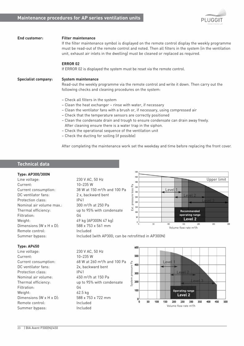
Type: AP300/300NLine voltage: 230 V AC, 50 HzCurrent: 10−235 WCurrent consumption: 38 W at 150 m³/h and 100 PaDC ventilator fans: 2 x, backward bentProtection class: IP41Nominal air volume max.: 300 m³/h at 250 PaThermal efficiency: up to 95% with condensateFiltration: G4Weight: 49 kg (AP300N 47 kg)Dimensions (W x H x D): 588 x 753 x 561 mmRemote control: IncludedSummer bypass: Included (with AP300; can be retrofitted in AP300N)
Type: AP450Line voltage: 230 V AC, 50 HzCurrent: 10−235 WCurrent consumption: 68 W at 260 m³/h and 100 PaDC ventilator fans: 2x, backward bentProtection class: IP41Nominal air volume: 450 m³/h at 150 Pa Thermal efficiency: up to 95% with condensate Filtration: G4Weight: 62.5 kgDimensions (W x H x D): 588 x 753 x 722 mmRemote control: IncludedSummer bypass: Included
End customer: Filter maintenanceIf the filter maintenance symbol is displayed on the remote control display the weekly programmemust be read-out of the remote control and noted. Then all filters in the system (in the ventilationunit, exhaust air inlets in the dwelling) must be cleaned or replaced as required.
ERROR 02If ERROR 02 is displayed the system must be reset via the remote control.
Specialist company: System maintenanceRead-out the weekly programme via the remote control and write it down. Then carry out the following checks and cleaning procedures on the system:
– Check all filters in the system – Clean the heat exchanger – rinse with water, if necessary– Clean the ventilator fans with a brush or, if necessary, using compressed air– Check that the temperature sensors are correctly positioned– Clean the condensate drain and trough to ensure condensate can drain away freely.
After cleaning ensure there is a water trap in the siphon.– Check the operational sequence of the ventilation unit– Check the ducting for soiling (if possible)
After completing the maintenance work set the weekday and time before replacing the front cover.
Recommended operating range
Level 2
Operating range
Level 2
Upper limit
Ext.
pres
sure
loss
Pa
Volume flow rate m³/h
Level 1Level 2
Level 3
Syst
em p
ress
ure
Pa
Volume flow rate m³/h
Level 1
Level 2
Level 3
24 | BIA Avent P300(N)/450
Immer frische Luft
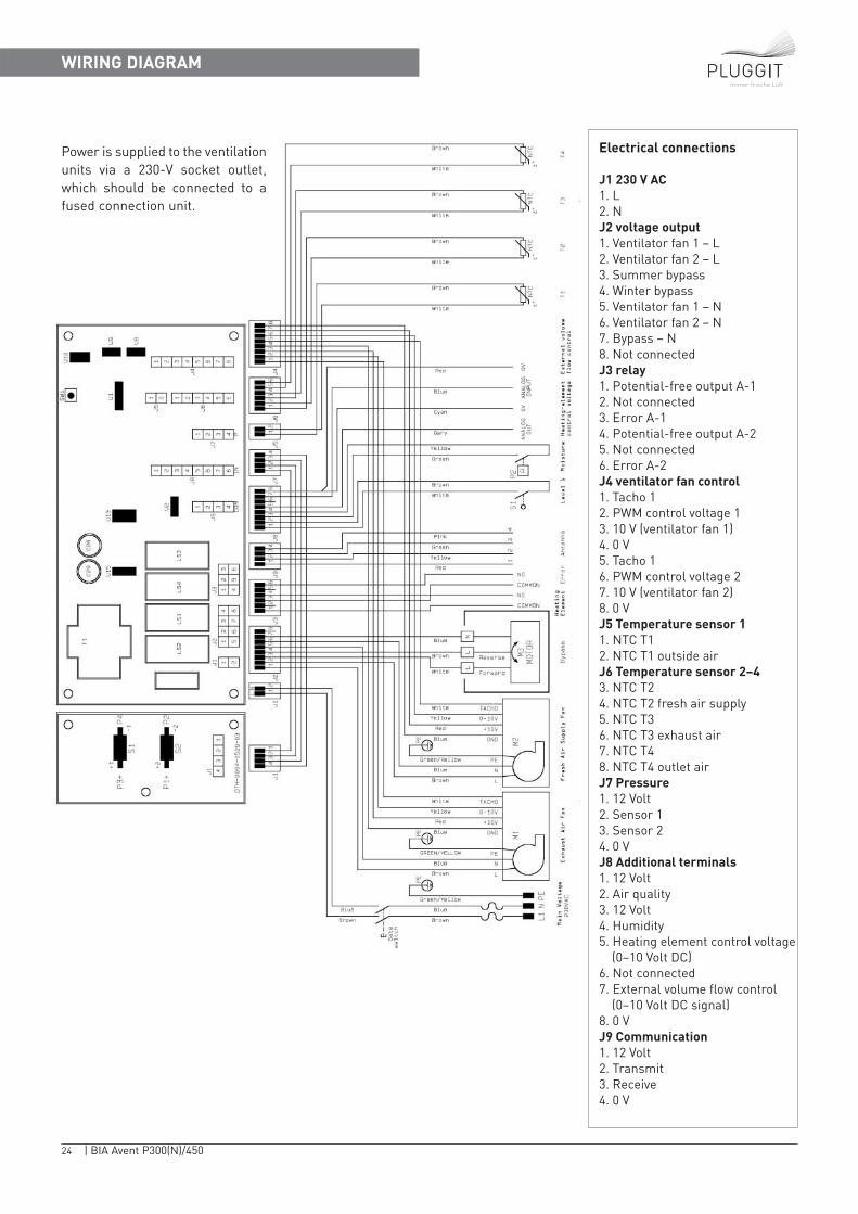
Electrical connections
J1 230 V AC1. L2. NJ2 voltage output1. Ventilator fan 1 − L2. Ventilator fan 2 − L3. Summer bypass4. Winter bypass5. Ventilator fan 1 − N6. Ventilator fan 2 − N7. Bypass − N8. Not connectedJ3 relay1. Potential-free output A-12. Not connected3. Error A-14. Potential-free output A-25. Not connected6. Error A-2J4 ventilator fan control1. Tacho 12. PWM control voltage 13. 10 V (ventilator fan 1)4. 0 V5. Tacho 16. PWM control voltage 27. 10 V (ventilator fan 2)8. 0 VJ5 Temperature sensor 11. NTC T12. NTC T1 outside airJ6 Temperature sensor 2−43. NTC T24. NTC T2 fresh air supply5. NTC T36. NTC T3 exhaust air7. NTC T48. NTC T4 outlet airJ7 Pressure1. 12 Volt2. Sensor 13. Sensor 24. 0 VJ8 Additional terminals1. 12 Volt2. Air quality3. 12 Volt4. Humidity5. Heating element control voltage
(0−10 Volt DC)6. Not connected7. External volume flow control
(0−10 Volt DC signal)8. 0 VJ9 Communication1. 12 Volt2. Transmit3. Receive4. 0 V
WIRING DIAGRAM
Power is supplied to the ventilationunits via a 230-V socket outlet,which should be connected to afused connection unit.
25 | BIA Avent P300(N)/450
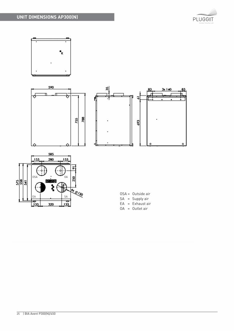
UNIT DIMENSIONS AP300(N)Immer frische Luft
OSA = Outside airSA = Supply airEA = Exhaust airOA = Outlet air
OSA OA
EA SA
26 | BIA Avent P 300(N)/450
Immer frische Luft
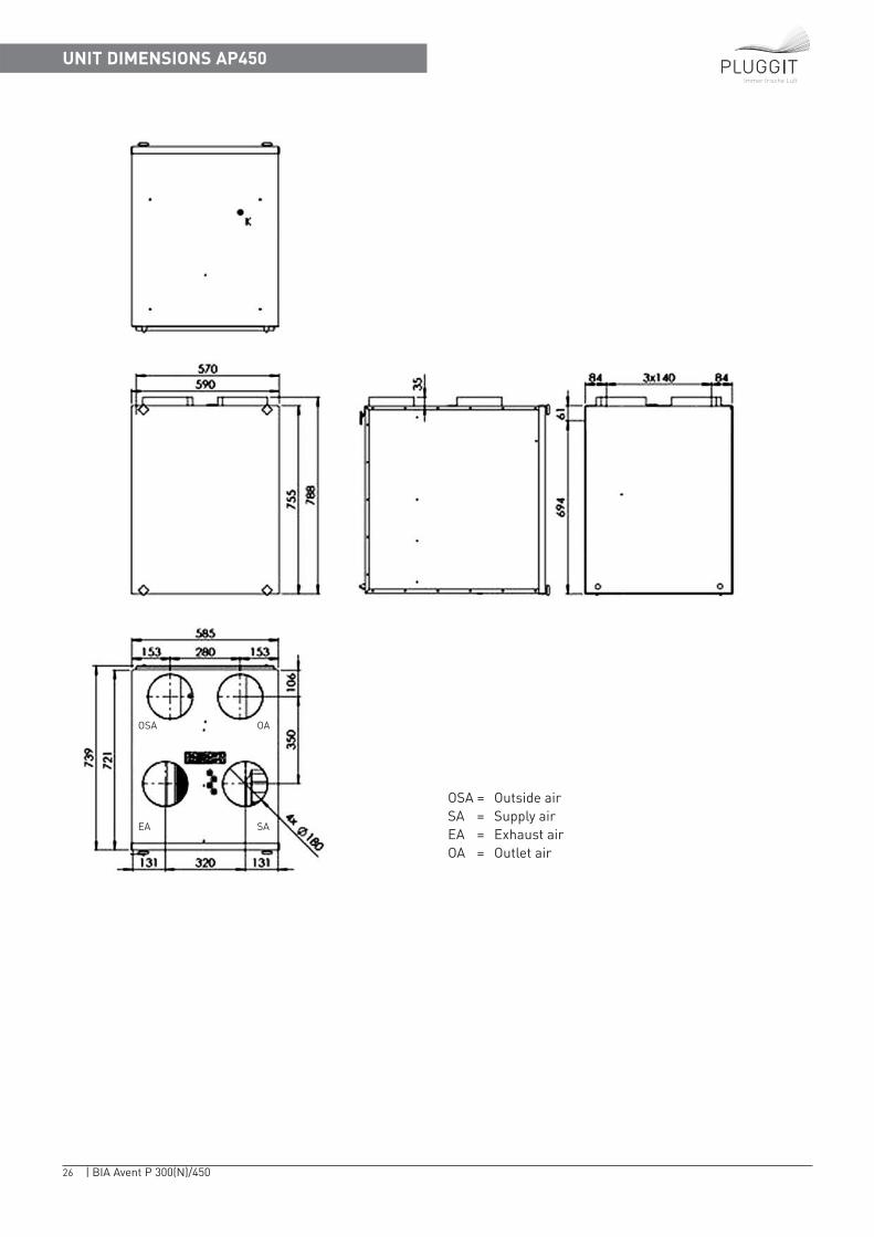
UNIT DIMENSIONS AP450
OSA = Outside airSA = Supply airEA = Exhaust airOA = Outlet air
OSA OA
EA SA
27 | BIA Avent P 300(N)/450
DECLARATION OF CONFORMITYImmer frische Luft
Immer frische Luft
Avent P180 (AP180)
28 | BIA Avent P300(N)/450
Immer frische Luft
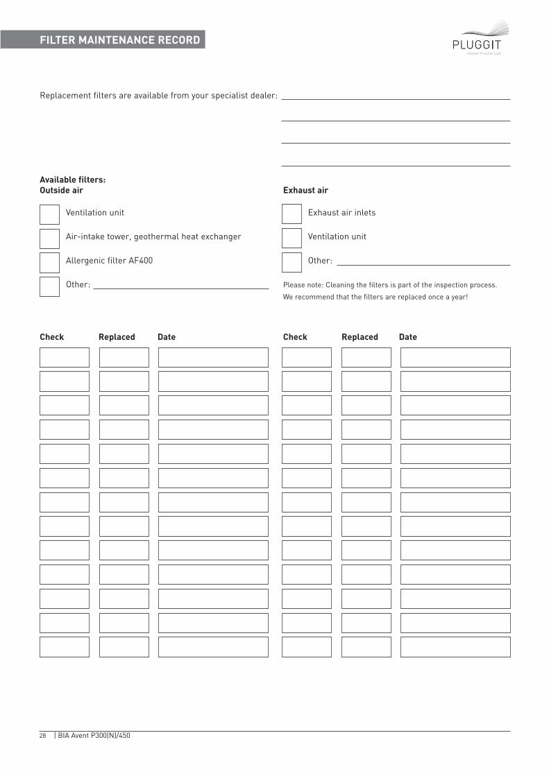
FILTER MAINTENANCE RECORD
Replacement filters are available from your specialist dealer:
Available filters:Outside air Exhaust air
Ventilation unit Exhaust air inlets
Air-intake tower, geothermal heat exchanger Ventilation unit
Allergenic filter AF400 Other:
Other: Please note: Cleaning the filters is part of the inspection process.
We recommend that the filters are replaced once a year!
Check Replaced Date Check Replaced Date
29 | BIA Avent P300(N)/450
Immer frische Luft
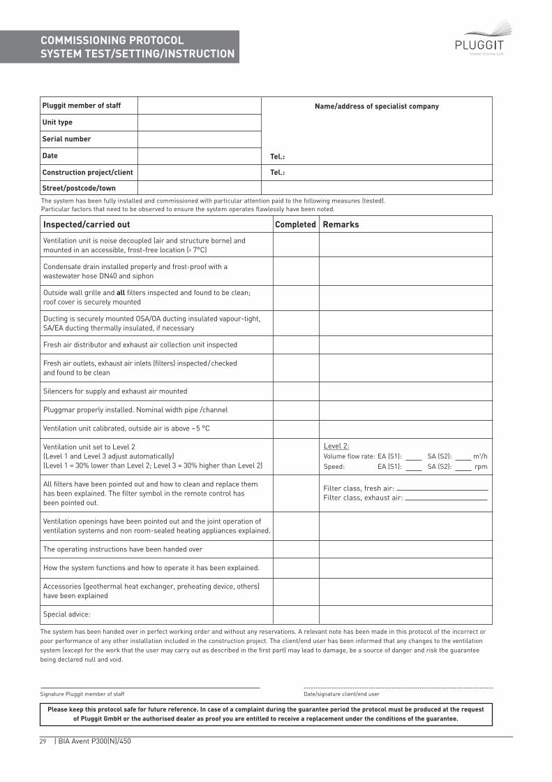
COMMISSIONING PROTOCOLSYSTEM TEST/SETTING/INSTRUCTION
Pluggit member of staff
Unit type
Serial number
Date
Construction project/client
Street/postcode/town
Name/address of specialist company
Level 2:Volume flow rate: EA (S1): SA (S2): m3/hSpeed: EA (S1): SA (S2): rpm
The system has been fully installed and commissioned with particular attention paid to the following measures (tested). Particular factors that need to be observed to ensure the system operates flawlessly have been noted.
Tel.:
Tel.:
Ventilation unit is noise decoupled (air and structure borne) and mounted in an accessible, frost-free location (› 7°C)
Condensate drain installed properly and frost-proof with a wastewater hose DN40 and siphon
Outside wall grille and all filters inspected and found to be clean; roof cover is securely mounted
Ducting is securely mounted OSA/OA ducting insulated vapour-tight,SA/EA ducting thermally insulated, if necessary
Fresh air distributor and exhaust air collection unit inspected
Fresh air outlets, exhaust air inlets (filters) inspected / checked and found to be clean
Silencers for supply and exhaust air mounted
Pluggmar properly installed. Nominal width pipe /channel
Ventilation unit calibrated, outside air is above – 5 °C
Ventilation unit set to Level 2 (Level 1 and Level 3 adjust automatically)(Level 1 = 30% lower than Level 2; Level 3 = 30% higher than Level 2)
All filters have been pointed out and how to clean and replace them has been explained. The filter symbol in the remote control has been pointed out.
Ventilation openings have been pointed out and the joint operation of ventilation systems and non room-sealed heating appliances explained.
The operating instructions have been handed over
How the system functions and how to operate it has been explained.
Accessories (geothermal heat exchanger, preheating device, others) have been explained
Special advice:
CompletedInspected/carried out Remarks
Signature Pluggit member of staff Date/signature client/end user
The system has been handed over in perfect working order and without any reservations. A relevant note has been made in this protocol of the incorrect orpoor performance of any other installation included in the construction project. The client/end user has been informed that any changes to the ventilationsystem (except for the work that the user may carry out as described in the first part) may lead to damage, be a source of danger and risk the guaranteebeing declared null and void.
Please keep this protocol safe for future reference. In case of a complaint during the guarantee period the protocol must be produced at the requestof Pluggit GmbH or the authorised dealer as proof you are entitled to receive a replacement under the conditions of the guarantee.
Filter class, fresh air: Filter class, exhaust air:

30 | BIA Avent P300(N)/450
Immer frische Luft
SPARE PARTS LIST
Service articlesAPFG4-300 Cartridge filter for AP300, filter class G4, 2 xAPFG4-450 Cartridge filter for AP450, filter class G4, 2 xAPFF7-300 Cartridge filter for AP300, filter class F7, 2 xAPFF7-450 Cartridge filter for AP450, filter class F7, 2 x
Spare partsAPFB1 Remote control (please supply the stock number – visible on rear of device)APAK1 Antenna, 2 meters (please supply version number – visible on the rear)APPL1MK2 PCB, completeAPWT300 Heat exchanger AP300APWT400 Heat exchanger AP450APVE8 Ventilator fan AP300APVE1 Ventilator fan AP450APFDS1 Cross-recess screw nut for front coverAPSS3 Summer bypass for AP300APSS4 Summer bypass for AP450APTS3-MK2 Temperature sensor (NTC), kitAPKO-MK2 Mounting kit AP300APKO4-MK2 Mounting kit AP450
AccessoriesAPKB1 Additional cable harness, connector J8APKB2 Additional cable harness, connector J3APAM2 Antenna, 7 meters

31 | BIA Avent P300(N)/450
Immer frische Luft
NOTES
BIA
Ave
nt P
300(
N)/
450_
engl
./V01
08.
2008
Pluggit GmbH | Wamslerstraße 2 | DE-81829 München | Telefon +49 (0)89 35 77 31 - 0 | Fax +49 (0)89 35 77 31 - 79www.pluggit.com | www.lueftungsblog.de
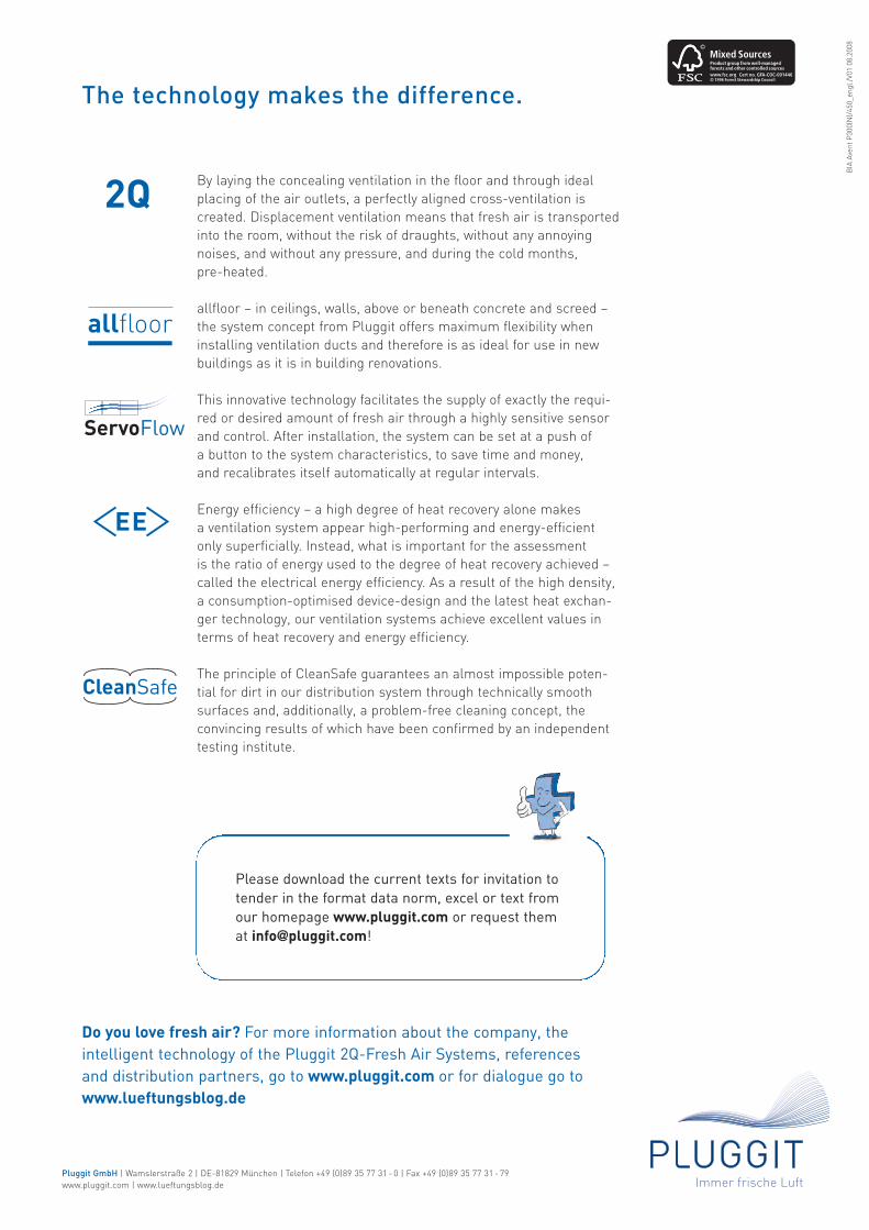
By laying the concealing ventilation in the floor and through ideal placing of the air outlets, a perfectly aligned cross-ventilation is created. Displacement ventilation means that fresh air is transportedinto the room, without the risk of draughts, without any annoyingnoises, and without any pressure, and during the cold months, pre-heated.
allfloor – in ceilings, walls, above or beneath concrete and screed –the system concept from Pluggit offers maximum flexibility wheninstalling ventilation ducts and therefore is as ideal for use in new buildings as it is in building renovations.
This innovative technology facilitates the supply of exactly the requi-red or desired amount of fresh air through a highly sensitive sensorand control. After installation, the system can be set at a push of a button to the system characteristics, to save time and money, and recalibrates itself automatically at regular intervals.
Energy efficiency – a high degree of heat recovery alone makes a ventilation system appear high-performing and energy-efficient only superficially. Instead, what is important for the assessment is the ratio of energy used to the degree of heat recovery achieved –called the electrical energy efficiency. As a result of the high density,a consumption-optimised device-design and the latest heat exchan-ger technology, our ventilation systems achieve excellent values interms of heat recovery and energy efficiency.
The principle of CleanSafe guarantees an almost impossible poten-tial for dirt in our distribution system through technically smooth surfaces and, additionally, a problem-free cleaning concept, the convincing results of which have been confirmed by an independenttesting institute.
Please download the current texts for invitation totender in the format data norm, excel or text fromour homepage www.pluggit.com or request themat [email protected]!
The technology makes the difference.
2Q
ServoFlow
CleanSafe
allfloor
Do you love fresh air? For more information about the company, theintelligent technology of the Pluggit 2Q-Fresh Air Systems, referencesand distribution partners, go to www.pluggit.com or for dialogue go towww.lueftungsblog.de