Embed Size (px)
Citation preview
Operating and installation instructionsUpright refrigerator with BioFresh compartment
30/08 7082648 - 01SKBes/SKB/KB/KBes 31/36/42 ... 6
Contents1 Appliance at a glance............................................ 21.1 Range of appliance use............................................ 21.2 Conformity................................................................ 21.3 Description of appliance and equipment.................. 21.4 External dimensions of the appliance....................... 31.5 Net@Home............................................................... 32 General safety information................................... 33 Controls and displays........................................... 43.1 Operating and control elements............................... 43.2 Temperature display................................................. 44 Putting into operation............................................ 44.1 Changing over the door hinges................................ 44.2 Insertion into a row of kitchen units........................... 74.3 Transporting the appliance....................................... 74.4 Installing the appliance............................................. 74.5 Disposing of packaging............................................ 84.6 Connecting the appliance......................................... 84.7 Switching on the appliance....................................... 85 Control.................................................................... 85.1 Saving energy.......................................................... 85.2 Brightness of the temperature display...................... 85.3 Child proofing........................................................... 85.4 Door alarm................................................................ 85.5 Refrigerator compartment........................................ 85.6 BioFresh compartment............................................. 106 Maintenance........................................................... 116.1 Cleaning the appliance............................................. 116.2 Changing the interior light with bulb.......................... 126.3 Customer service..................................................... 127 Malfunction............................................................. 128 Decommissioning.................................................. 138.1 Switching off the appliance....................................... 138.2 Taking the appliance out of service.......................... 139 Disposing of the appliance................................... 13
The manufacturer works constantly on the further developmentof all the types and models. Therefore please understand that wehave to reserve the right to make design, equipment and techni-cal modifications.To get to know all the benefits of your new appliance, please readthe information contained in these instructions carefully.The instructions apply to several models. Differences may occur.Text relating only to specific appliances is marked with an aster-isk (*).Instructions for action are marked with a , the results ofaction are marked with a .
1 Appliance at a glance1.1 Range of appliance useThe appliance is suited only for cooling food. In the case of com-mercial food cooling, the pertinent statutory regulations have tobe observed. The appliance is not suited for storing and coolingpharmaceuticals, blood plasma, laboratory preparations or sim-ilar substances and products subject to the Medical Devices Di-rective 2007/47/EC. Any misuse of the appliance may result indamage to or spoilage of the stored goods. Furthermore, the ap-pliance is unsuited for use in areas exposed to an explosion haz-ard.The appliance is set to operate within specific ambient temper-ature limits according to its climate rating. The correct climaterating for your appliance is indicated on the type plate.
Noteu Compliance with the ambient temperatures indicated is re-
quired, otherwise the cooling performance is reduced.
Climate rat-ing
for ambient temperatures of
SN 10 °C to 32 °CN 16 °C to 32 °CST 16 °C to 38 °CT 16 °C to 43 °C
1.2 ConformityThe refrigerant circuit has been tested for leaks. The appliancecomplies with current safety regulations and EC directives2006/95/EC and 2004/108/EC.
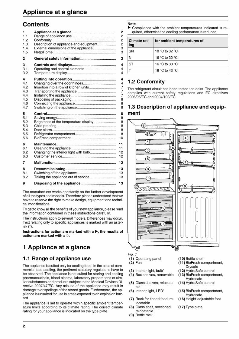
1.3 Description of appliance and equip-ment
Fig. 1 (1) Operating panel (10) Bottle shelf(2) Fan (11) BioFresh compartment,
Drysafe(3) Interior light, bulb* (12) HydroSafe control(4) Box shelves, removable (13) BioFresh compartment,
Hydrosafe(5) Glass shelves, relocata-
ble(14) HydroSafe control
(6) Interior light, LED* (15) BioFresh compartment,Hydrosafe
(7) Rack for tinned food, re-locatable
(16) Height-adjustable foot
(8) Glass shelf, sectioned,relocatable
(17) Type plate
(9) Bottle rack
Appliance at a glance
2
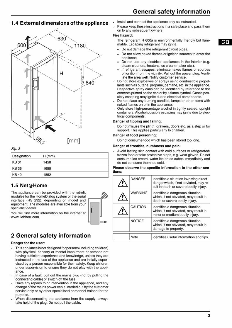
1.4 External dimensions of the appliance
Fig. 2 Designation H (mm)KB 31 1458KB 36 1655KB 42 1852
1.5 Net@HomeThe appliance can be provided with the retrofitmodules for the HomeDialog system or the serialinterface (RS 232), depending on model andequipment. The modules are available from yourspecialist dealer.You will find more information on the internet atwww.liebherr.com.
2 General safety informationDanger for the user:- This appliance is not designed for persons (including children)
with physical, sensory or mental impairment or persons nothaving sufficient experience and knowledge, unless they areinstructed in the use of the appliance and are initially super-vised by a person responsible for their safety. Keep childrenunder supervision to ensure they do not play with the appli-ance.
- In case of a fault, pull out the mains plug (not by pulling theconnecting cable) or switch off the fuse.
- Have any repairs to or intervention in the appliance, and anychange of the mains power cable, carried out by the customerservice only or by other specialised personnel trained for thepurpose.
- When disconnecting the appliance from the supply, alwaystake hold of the plug. Do not pull the cable.
- Install and connect the appliance only as instructed.- Please keep these instructions in a safe place and pass them
on to any subsequent owners.Fire hazard:- The refrigerant R 600a is environmentally friendly but flam-
mable. Escaping refrigerant may ignite.• Do not damage the refrigerant circuit pipes.• Do not allow naked flames or ignition sources to enter the
appliance.• Do not use any electrical appliances in the interior (e.g.
steam cleaners, heaters, ice cream maker etc.).• If refrigerant escapes: eliminate naked flames or sources
of ignition from the vicinity. Pull out the power plug. Venti-late the area well. Notify customer service.
- Do not store explosives or sprays using combustible propel-lants such as butane, propane, pentane, etc. in the appliance.Respective spray cans can be identified by reference to thecontents printed on the can or by a flame symbol. Gases pos-sibly escaping may ignite due to electrical components.
- Do not place any burning candles, lamps or other items withnaked flames on or in the appliance.
- Only store high-percentage alcohol in tightly sealed, uprightcontainers. Alcohol possibly escaping may ignite due to elec-trical components.
Danger of tipping and falling:- Do not misuse the plinth, drawers, doors etc. as a step or for
support. This applies particularly to children.Danger of food poisoning:- Do not consume food which has been stored too long.Danger of frostbite, numbness and pain:- Avoid lasting skin contact with cold surfaces or refrigerated/
frozen food or take protective steps, e.g. wear gloves. Do notconsume ice cream, water ice or ice cubes immediately anddo not consume them too cold.
Please observe the specific information in the other sec-tions:
DANGER identifies a situation involving directdanger which, if not obviated, may re-sult in death or severe bodily injury.
WARNING identifies a dangerous situationwhich, if not obviated, may result indeath or severe bodily injury.
CAUTION identifies a dangerous situationwhich, if not obviated, may result inminor or medium bodily injury.
NOTICE identifies a dangerous situationwhich, if not obviated, may result indamage to property.
Note identifies useful information and tips.
General safety information
3
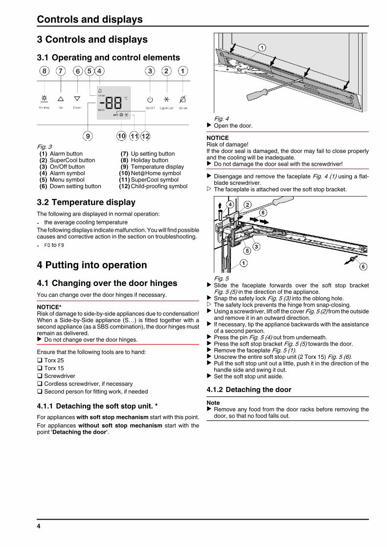
3 Controls and displays3.1 Operating and control elements
Fig. 3 (1) Alarm button (7) Up setting button(2) SuperCool button (8) Holiday button(3) On/Off button (9) Temperature display(4) Alarm symbol (10) Net@Home symbol(5) Menu symbol (11) SuperCool symbol(6) Down setting button (12) Child-proofing symbol
3.2 Temperature displayThe following are displayed in normal operation:- the average cooling temperatureThe following displays indicate malfunction. You will find possiblecauses and corrective action in the section on troubleshooting.- F0 to F9
4 Putting into operation4.1 Changing over the door hingesYou can change over the door hinges if necessary.NOTICE*Risk of damage to side-by-side appliances due to condensation!When a Side-by-Side appliance (S…) is fitted together with asecond appliance (as a SBS combination), the door hinges mustremain as delivered.u Do not change over the door hinges.Ensure that the following tools are to hand:q Torx 25q Torx 15q Screwdriverq Cordless screwdriver, if necessaryq Second person for fitting work, if needed
4.1.1 Detaching the soft stop unit. *For appliances with soft stop mechanism start with this point.For appliances without soft stop mechanism start with thepoint 'Detaching the door'.
Fig. 4 u Open the door.NOTICERisk of damage!If the door seal is damaged, the door may fail to close properlyand the cooling will be inadequate.u Do not damage the door seal with the screwdriver!u Disengage and remove the faceplate Fig. 4 (1) using a flat-
blade screwdriver.w The faceplate is attached over the soft stop bracket.
Fig. 5 u Slide the faceplate forwards over the soft stop bracket
Fig. 5 (5) in the direction of the appliance.u Snap the safety lock Fig. 5 (3) into the oblong hole.w The safety lock prevents the hinge from snap-closing.u Using a screwdriver, lift off the cover Fig. 5 (2) from the outside
and remove it in an outward direction.u If necessary, tip the appliance backwards with the assistance
of a second person.u Press the pin Fig. 5 (4) out from underneath.u Press the soft stop bracket Fig. 5 (5) towards the door.u Remove the faceplate Fig. 5 (1).u Unscrew the entire soft stop unit (2 Torx 15) Fig. 5 (6).u Pull the soft stop unit out a little, push it in the direction of the
handle side and swing it out.u Set the soft stop unit aside.
4.1.2 Detaching the doorNoteu Remove any food from the door racks before removing the
door, so that no food falls out.
Controls and displays
4
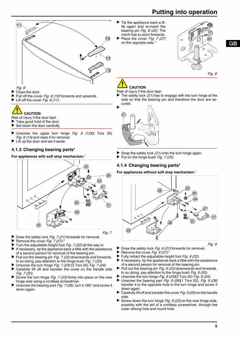
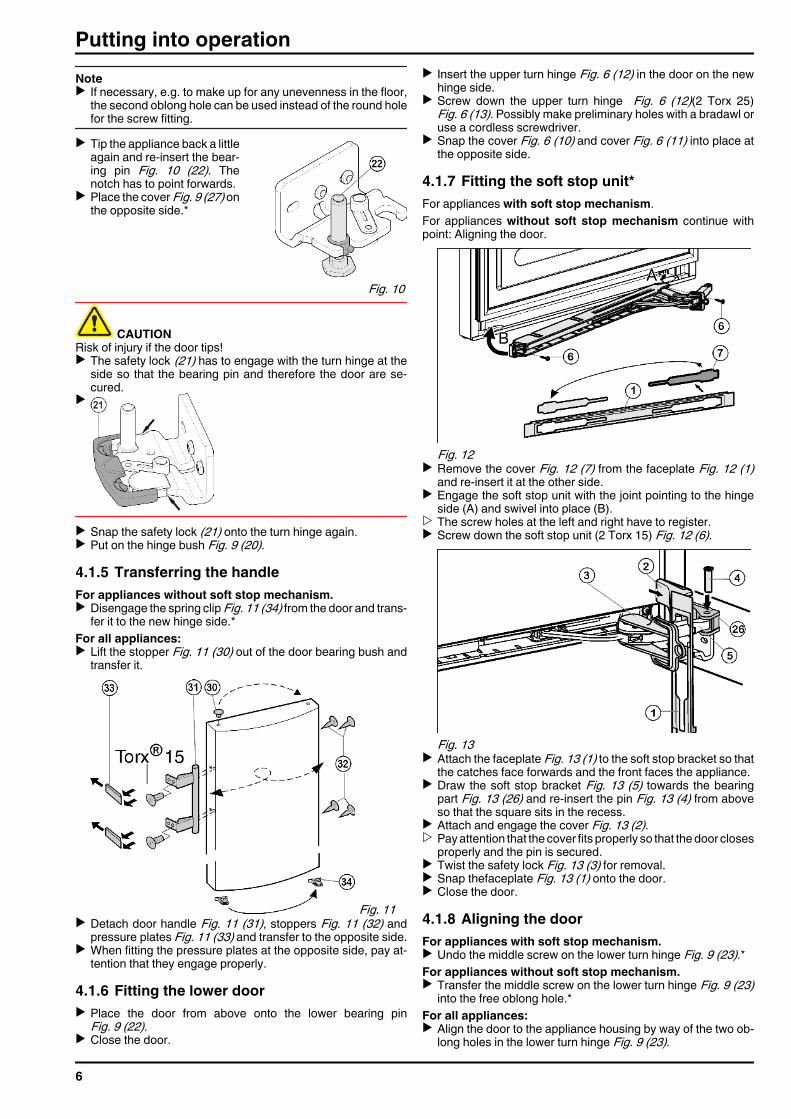
Fig. 6 u Close the door.u Pull off the cover Fig. 6 (10) forwards and upwards.u Lift off the cover Fig. 6 (11).
CAUTIONRisk of injury if the door tips!u Take good hold of the door.u Set down the door carefully.u Unscrew the upper turn hinge Fig. 6 (12)(2 Torx 25)
Fig. 6 (13) and raise it for removal.u Lift up the door and set it aside.
4.1.3 Changing bearing parts*For appliances with soft stop mechanism.*
Fig. 7 u Draw the safety lock Fig. 7 (21) forwards for removal.u Remove the cover Fig. 7 (27).*u Turn the adjustable-height foot Fig. 7 (22) all the way in.u If necessary, tip the appliance back a little with the assistance
of a second person for removal of the bearing pin.u Pull out the bearing pin Fig. 7 (22) downwards and forwards.
In so doing, pay attention to the hinge bush Fig. 7 (20).u Unscrew the turn hinge Fig. 7 (23) (3 Torx 25) Fig. 7 (24).u Carefully lift off and transfer the cover on the handle side
Fig. 7 (25).u Screw the turn hinge Fig. 7 (23) firmly into place on the new
hinge side using a cordless screwdriver.u Unscrew the bearing part Fig. 7 (26), turn it 180° and screw it
down again.
u Tip the appliance back a lit-tle again and re-insert thebearing pin Fig. 8 (22). Thenotch has to point forwards.
u Place the cover Fig. 7 (27)on the opposite side.*
Fig. 8
CAUTIONRisk of injury if the door tips!u The safety lock (21) has to engage with the turn hinge at the
side so that the bearing pin and therefore the door are se-cured.
u
u Snap the safety lock (21) onto the turn hinge again.u Put on the hinge bush Fig. 7 (20).
4.1.4 Changing bearing parts*For appliances without soft stop mechanism.*
Fig. 9 u Draw the safety lock Fig. 9 (21) forwards for removal.u Remove the cover Fig. 9 (27).*u Fully retract the adjustable-height foot Fig. 9 (22).u If necessary, tip the appliance back a little with the assistance
of a second person for removal of the bearing pin.u Pull out the bearing pin Fig. 9 (22) downwards and forwards.
In so doing, pay attention to the hinge bush Fig. 9 (20).u Unscrew the turn hinge Fig. 9 (23)(2 Torx 25) Fig. 9 (24).u Unscrew the bearing part Fig. 9 (26)(1 Torx 25), Fig. 9 (28)
transfer it to the opposite hole in the turn hinge and screw itdown again.
u Carefully lift off and transfer the cover Fig. 9 (25) on the handleside.
u Screw down the turn hinge Fig. 9 (23) on the new hinge side,possibly with the aid of a cordless screwdriver, through theouter oblong hole and round hole.
Putting into operation
5
Noteu If necessary, e.g. to make up for any unevenness in the floor,
the second oblong hole can be used instead of the round holefor the screw fitting.
u Tip the appliance back a littleagain and re-insert the bear-ing pin Fig. 10 (22). Thenotch has to point forwards.
u Place the cover Fig. 9 (27) onthe opposite side.*
Fig. 10
CAUTIONRisk of injury if the door tips!u The safety lock (21) has to engage with the turn hinge at the
side so that the bearing pin and therefore the door are se-cured.
u
u Snap the safety lock (21) onto the turn hinge again.u Put on the hinge bush Fig. 9 (20).
4.1.5 Transferring the handleFor appliances without soft stop mechanism.u Disengage the spring clip Fig. 11 (34) from the door and trans-
fer it to the new hinge side.*For all appliances:u Lift the stopper Fig. 11 (30) out of the door bearing bush and
transfer it.
Fig. 11 u Detach door handle Fig. 11 (31), stoppers Fig. 11 (32) and
pressure plates Fig. 11 (33) and transfer to the opposite side.u When fitting the pressure plates at the opposite side, pay at-
tention that they engage properly.
4.1.6 Fitting the lower dooru Place the door from above onto the lower bearing pin
Fig. 9 (22).u Close the door.
u Insert the upper turn hinge Fig. 6 (12) in the door on the newhinge side.
u Screw down the upper turn hinge Fig. 6 (12)(2 Torx 25)Fig. 6 (13). Possibly make preliminary holes with a bradawl oruse a cordless screwdriver.
u Snap the cover Fig. 6 (10) and cover Fig. 6 (11) into place atthe opposite side.
4.1.7 Fitting the soft stop unit*For appliances with soft stop mechanism.For appliances without soft stop mechanism continue withpoint: Aligning the door.
Fig. 12 u Remove the cover Fig. 12 (7) from the faceplate Fig. 12 (1)
and re-insert it at the other side.u Engage the soft stop unit with the joint pointing to the hinge
side (A) and swivel into place (B).w The screw holes at the left and right have to register.u Screw down the soft stop unit (2 Torx 15) Fig. 12 (6).
Fig. 13 u Attach the faceplate Fig. 13 (1) to the soft stop bracket so that
the catches face forwards and the front faces the appliance.u Draw the soft stop bracket Fig. 13 (5) towards the bearing
part Fig. 13 (26) and re-insert the pin Fig. 13 (4) from aboveso that the square sits in the recess.
u Attach and engage the cover Fig. 13 (2).w Pay attention that the cover fits properly so that the door closes
properly and the pin is secured.u Twist the safety lock Fig. 13 (3) for removal.u Snap thefaceplate Fig. 13 (1) onto the door.u Close the door.
4.1.8 Aligning the doorFor appliances with soft stop mechanism.u Undo the middle screw on the lower turn hinge Fig. 9 (23).*For appliances without soft stop mechanism.u Transfer the middle screw on the lower turn hinge Fig. 9 (23)
into the free oblong hole.*For all appliances:u Align the door to the appliance housing by way of the two ob-
long holes in the lower turn hinge Fig. 9 (23).
Putting into operation
6
u Tighten the screws.
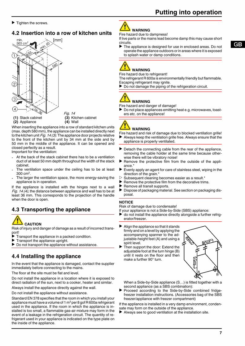
4.2 Insertion into a row of kitchen units
Fig. 14 (1) Stack cabinet (3) Kitchen cabinet(2) Appliance (4) Wall
When inserting the appliance into a row of standard kitchen units(max. depth 580 mm), the appliance can be installed directly nextto the kitchen unit Fig. 14 (3). The appliance door projects relativeto the front of the kitchen unit by 34 mm at the side and by50 mm in the middle of the appliance. It can be opened andclosed perfectly as a result.Important for the ventilation:- At the back of the stack cabinet there has to be a ventilation
duct of at least 50 mm depth throughout the width of the stackcabinet.
- The ventilation space under the ceiling has to be at least300 cm2.
- The larger the ventilation space, the more energy-saving theappliance is in operation.
If the appliance is installed with the hinges next to a wallFig. 14 (4), the distance between appliance and wall has to be atleast 36 mm. This corresponds to the projection of the handlewhen the door is open.
4.3 Transporting the appliance
CAUTIONRisk of injury and danger of damage as a result of incorrect trans-port!u Transport the appliance in a packed condition.u Transport the appliance upright.u Do not transport the appliance without assistance.
4.4 Installing the applianceIn the event that the appliance is damaged, contact the supplierimmediately before connecting to the mains.The floor at the site must be flat and level.Do not install the appliance in a location where it is exposed todirect radiation of the sun, next to a cooker, heater and similar.Always install the appliance directly against the wall.Do not install the appliance without assistance.Standard EN 378 specifies that the room in which you install yourappliance must have a volume of 1 m3 per 8 gof R 600a refrigerantused in the appliance. If the room in which the appliance is in-stalled is too small, a flammable gas-air mixture may form in theevent of a leakage in the refrigeration circuit. The quantity of re-frigerant used in your appliance is indicated on the type plate onthe inside of the appliance.
WARNINGFire hazard due to dampness!If live parts or the mains lead become damp this may cause shortcircuits.u The appliance is designed for use in enclosed areas. Do not
operate the appliance outdoors or in areas where it is exposedto splash water or damp conditions.
WARNINGFire hazard due to refrigerant!The refrigerant R 600a is environmentally friendly but flammable.Escaping refrigerant may ignite.u Do not damage the piping of the refrigeration circuit.
WARNINGFire hazard and danger of damage!u Do not place appliances emitting heat e.g. microwaves, toast-
ers etc. on the appliance!
WARNINGFire hazard and risk of damage due to blocked ventilation grille!u Always keep the ventilation grille free. Always ensure that the
appliance is properly ventilated.u Detach the connecting cable from the rear of the appliance,
removing the cable holder at the same time because other-wise there will be vibratory noise!
u Remove the protective film from the outside of the appli-ance.*
u Evenly apply an agent for care of stainless steel, wiping in thedirection of the grain.*
w Subsequent cleaning becomes easier as a result.*u Remove the protective film from the decorative trims.u Remove all transit supports.u Dispose of packaging material. See section on packaging dis-
posal.NOTICERisk of damage due to condensate!If your appliance is not a Side-by-Side (SBS) appliance:u do not install the appliance directly alongside a further refrig-
erator/freezer.u Align the appliance so that it stands
firmly and on a level by applying theaccompanying spanner to the ad-justable-height feet (A) and using aspirit level.
u Then support the door: Extend theadjustable foot at the turn hinge (B)until it rests on the floor and thenmake a further 90° turn.
When a Side-by-Side appliance (S…) is fitted together with asecond appliance (as a SBS combination):
u Proceed according to the Side-by-Side combined fridge-freezer installation instructions. (Accessories bag of the SBSfreezer/appliance with freezer compartment)
If the appliance is installed in a very damp environment, conden-sate may form on the outside of the appliance.u Always see to good ventilation at the installation site.
Putting into operation
7
4.5 Disposing of packaging
WARNINGDanger of suffocation due to packing material and plastic film!u Do not allow children to play with packing material.The packaging is made of recyclable materials:- corrugated board/cardboard- EPS moulded parts- polythene bags and sheets- polypropylene strapsu Take the packaging material to an official collecting point.
4.6 Connecting the applianceNOTICERisk of damage to the electronic control system!u Do not use stand-alone inverters (conversion of d.c. to a.c./
three-phase) or energy saving plugs.
WARNINGFire and overheating hazard!u Do not use extension cables or multiple socket outlets.The type of current (alternating current) and voltage at the instal-lation site have to conform with the data on the type plate (seesection on description of appliance and equipment).Connect the appliance only with a properly installedsocket outlet with earthing contact. The socket outletmust be fused with 10 A or higher.It must be easily accessible so that the appliance canbe quickly disconnected from the supply in an emer-gency.u Check the electrical connection.u Clean the appliance. More information on this is in the section
on cleaning.u Plug in the power plug.
4.7 Switching on the applianceu Press On/Off button Fig. 3 (3).w The temperature display indicates the current temperature.w The interior light is on when the door is open.
5 Control5.1 Saving energyu Always pay attention to good ventilation.u Keep the time the appliance is open to a minimum.u Store food logically.u First cool warm food to room temperature before storing it .Accumulated dust increases the energy con-sumption:u Once a year, dust the refrigerating unit to-
gether with the metal grille of the heat ex-changer at the back of the appliance.
5.2 Brightness of the temperature dis-playYou can adjust the brightness of the temperature display to thelight conditions of the room in which the appliance is installed.
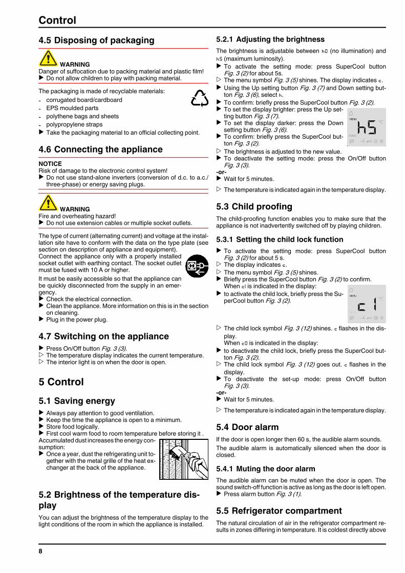
5.2.1 Adjusting the brightnessThe brightness is adjustable between h0 (no illumination) andh5 (maximum luminosity).u To activate the setting mode: press SuperCool button
Fig. 3 (2) for about 5s.w The menu symbol Fig. 3 (5) shines. The display indicates c.u Using the Up setting button Fig. 3 (7) and Down setting but-
ton Fig. 3 (6), select h.u To confirm: briefly press the SuperCool button Fig. 3 (2).u To set the display brighter: press the Up set-
ting button Fig. 3 (7).u To set the display darker: press the Down
setting button Fig. 3 (6).u To confirm: briefly press the SuperCool but-
ton Fig. 3 (2).w The brightness is adjusted to the new value.u To deactivate the setting mode: press the On/Off button
Fig. 3 (3).-or-u Wait for 5 minutes.w The temperature is indicated again in the temperature display.
5.3 Child proofingThe child-proofing function enables you to make sure that theappliance is not inadvertently switched off by playing children.
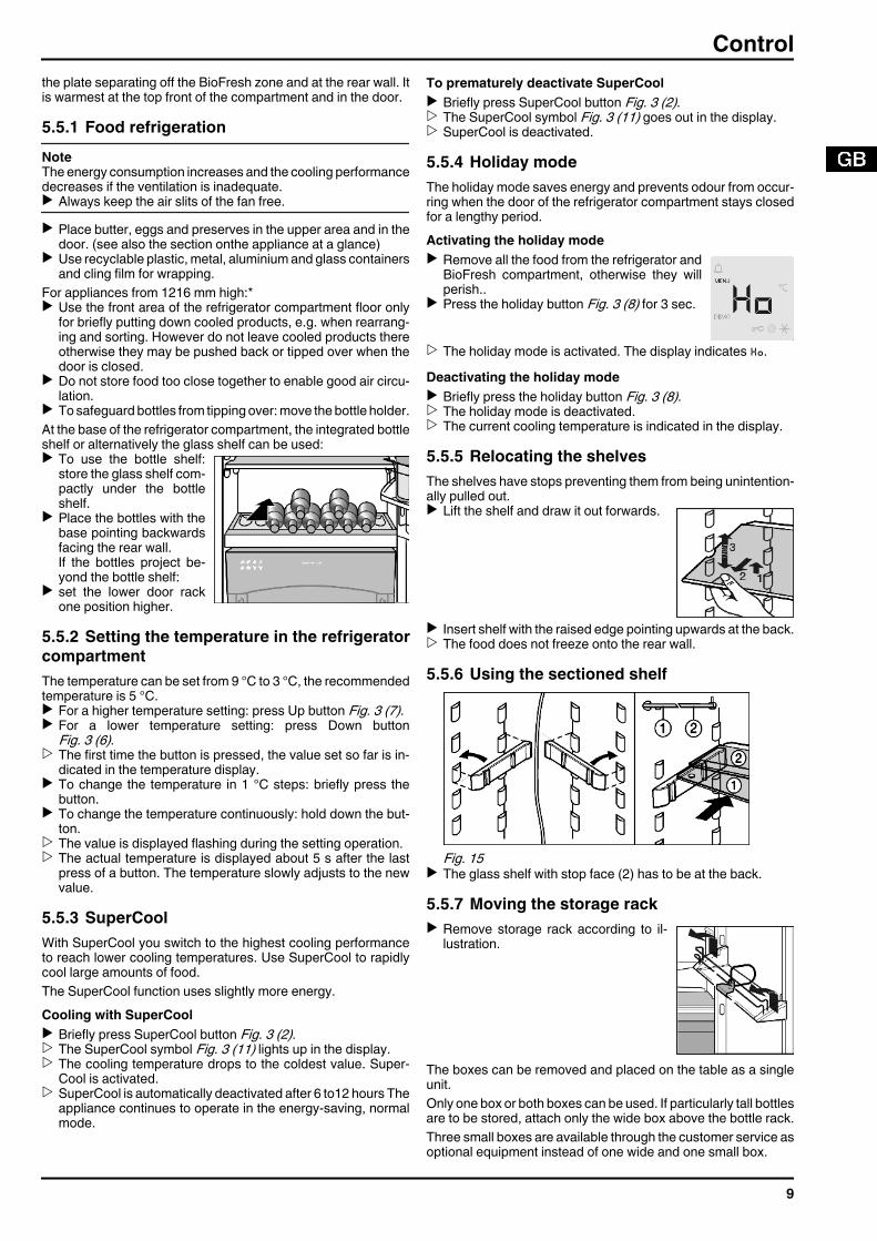
5.3.1 Setting the child lock functionu To activate the setting mode: press SuperCool button
Fig. 3 (2) for about 5 s.w The display indicates c.w The menu symbol Fig. 3 (5) shines.u Briefly press the SuperCool button Fig. 3 (2) to confirm.
When c1 is indicated in the display:u to activate the child lock, briefly press the Su-
perCool button Fig. 3 (2).
w The child lock symbol Fig. 3 (12) shines. c flashes in the dis-play.When c0 is indicated in the display:
u to deactivate the child lock, briefly press the SuperCool but-ton Fig. 3 (2).
w The child lock symbol Fig. 3 (12) goes out. c flashes in thedisplay.
u To deactivate the set-up mode: press On/Off buttonFig. 3 (3).
-or-u Wait for 5 minutes.w The temperature is indicated again in the temperature display.
5.4 Door alarmIf the door is open longer then 60 s, the audible alarm sounds.The audible alarm is automatically silenced when the door isclosed.
5.4.1 Muting the door alarmThe audible alarm can be muted when the door is open. Thesound switch-off function is active as long as the door is left open.u Press alarm button Fig. 3 (1).
5.5 Refrigerator compartmentThe natural circulation of air in the refrigerator compartment re-sults in zones differing in temperature. It is coldest directly above
Control
8
the plate separating off the BioFresh zone and at the rear wall. Itis warmest at the top front of the compartment and in the door.
5.5.1 Food refrigerationNoteThe energy consumption increases and the cooling performancedecreases if the ventilation is inadequate.u Always keep the air slits of the fan free.u Place butter, eggs and preserves in the upper area and in the
door. (see also the section onthe appliance at a glance)u Use recyclable plastic, metal, aluminium and glass containers
and cling film for wrapping.For appliances from 1216 mm high:*u Use the front area of the refrigerator compartment floor only
for briefly putting down cooled products, e.g. when rearrang-ing and sorting. However do not leave cooled products thereotherwise they may be pushed back or tipped over when thedoor is closed.
u Do not store food too close together to enable good air circu-lation.
u To safeguard bottles from tipping over: move the bottle holder.At the base of the refrigerator compartment, the integrated bottleshelf or alternatively the glass shelf can be used:u To use the bottle shelf:
store the glass shelf com-pactly under the bottleshelf.
u Place the bottles with thebase pointing backwardsfacing the rear wall.If the bottles project be-yond the bottle shelf:
u set the lower door rackone position higher.
5.5.2 Setting the temperature in the refrigeratorcompartmentThe temperature can be set from 9 °C to 3 °C, the recommendedtemperature is 5 °C.u For a higher temperature setting: press Up button Fig. 3 (7).u For a lower temperature setting: press Down button
Fig. 3 (6).w The first time the button is pressed, the value set so far is in-
dicated in the temperature display.u To change the temperature in 1 °C steps: briefly press the
button.u To change the temperature continuously: hold down the but-
ton.w The value is displayed flashing during the setting operation.w The actual temperature is displayed about 5 s after the last
press of a button. The temperature slowly adjusts to the newvalue.
5.5.3 SuperCoolWith SuperCool you switch to the highest cooling performanceto reach lower cooling temperatures. Use SuperCool to rapidlycool large amounts of food.The SuperCool function uses slightly more energy.Cooling with SuperCoolu Briefly press SuperCool button Fig. 3 (2).w The SuperCool symbol Fig. 3 (11) lights up in the display.w The cooling temperature drops to the coldest value. Super-
Cool is activated.w SuperCool is automatically deactivated after 6 to12 hours The
appliance continues to operate in the energy-saving, normalmode.
To prematurely deactivate SuperCoolu Briefly press SuperCool button Fig. 3 (2).w The SuperCool symbol Fig. 3 (11) goes out in the display.w SuperCool is deactivated.
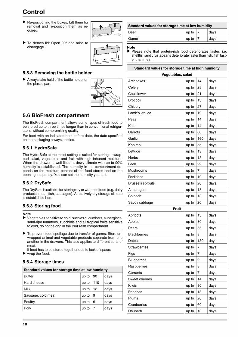
5.5.4 Holiday modeThe holiday mode saves energy and prevents odour from occur-ring when the door of the refrigerator compartment stays closedfor a lengthy period.Activating the holiday modeu Remove all the food from the refrigerator and
BioFresh compartment, otherwise they willperish..
u Press the holiday button Fig. 3 (8) for 3 sec.
w The holiday mode is activated. The display indicates Ho.Deactivating the holiday modeu Briefly press the holiday button Fig. 3 (8).w The holiday mode is deactivated.w The current cooling temperature is indicated in the display.
5.5.5 Relocating the shelvesThe shelves have stops preventing them from being unintention-ally pulled out.u Lift the shelf and draw it out forwards.
u Insert shelf with the raised edge pointing upwards at the back.w The food does not freeze onto the rear wall.
5.5.6 Using the sectioned shelf
Fig. 15 u The glass shelf with stop face (2) has to be at the back.
5.5.7 Moving the storage racku Remove storage rack according to il-
lustration.
The boxes can be removed and placed on the table as a singleunit.Only one box or both boxes can be used. If particularly tall bottlesare to be stored, attach only the wide box above the bottle rack.Three small boxes are available through the customer service asoptional equipment instead of one wide and one small box.
Control
9
u Re-positioning the boxes: Lift them forremoval and re-position them as re-quired.
u To detach lid: Open 90° and raise todisengage.
5.5.8 Removing the bottle holderu Always take hold of the bottle holder on
the plastic part.
5.6 BioFresh compartmentThe BioFresh compartment allows some types of fresh food tobe stored up to three times longer than in conventional refriger-ators, without compromising quality.For food with an indicated best before date, the date specifiedon the packaging always applies.
5.6.1 HydroSafeThe HydroSafe at the moist setting is suited for storing unwrap-ped salad, vegetables and fruit with high inherent moisture.When the drawer is well filled, a dewy climate with up to 90%humidity is established. The humidity in the compartment de-pends on the moisture content of the food stored and on theopening frequency. You can set the humidity yourself.
5.6.2 DrySafeThe DrySafe is suitable for storing dry or wrapped food (e.g. dairyproducts, meat, fish, sausages). A relatively dry storage climateis established here.
5.6.3 Storing foodNoteu Vegetables sensitive to cold, such as cucumbers, aubergines,
semi-ripe tomatoes, zucchinis and all tropical fruits sensitiveto cold, do not belong in the BioFresh compartment.
u To prevent food spoilage due to transfer of germs: Store un-wrapped animal and vegetable products separate from oneanother in the drawers. This also applies to different sorts ofmeat.If food has to be stored together due to lack of space:
u wrap the food.
5.6.4 Storage timesStandard values for storage time at low humidityButter up to 90 daysHard cheese up to 110 daysMilk up to 12 daysSausage, cold meat up to 9 daysPoultry up to 6 daysPork up to 7 days
Standard values for storage time at low humidityBeef up to 7 daysGame up to 7 days
Noteu Please note that protein-rich food deteriorates faster, i.e.
shellfish and crustaceans deteriorate faster than fish, fish fast-er than meat.
Standard values for storage time at high humidityVegetables, salad
Artichokes up to 14 daysCelery up to 28 daysCauliflower up to 21 daysBroccoli up to 13 daysChicory up to 27 daysLamb's lettuce up to 19 daysPeas up to 14 daysKale up to 14 daysCarrots up to 80 daysGarlic up to 160 daysKohlrabi up to 55 daysLettuce up to 13 daysHerbs up to 13 daysLeek up to 29 daysMushrooms up to 7 daysRadishes up to 10 daysBrussels sprouts up to 20 daysAsparagus up to 18 daysSpinach up to 13 daysSavoy cabbage up to 20 days
FruitApricots up to 13 daysApples up to 80 daysPears up to 55 daysBlackberries up to 3 daysDates up to 180 daysStrawberries up to 7 daysFigs up to 7 daysBlueberries up to 9 daysRaspberries up to 3 daysCurrants up to 7 daysSweet cherries up to 14 daysKiwis up to 80 daysPeaches up to 13 daysPlums up to 20 daysCranberries up to 60 daysRhubarb up to 13 days
Control
10
Standard values for storage time at high humidityGooseberries up to 13 daysGrapes up to 29 days
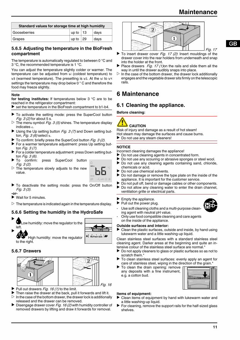
5.6.5 Adjusting the temperature in the BioFreshcompartmentThe temperature is automatically regulated to between 0 °C and3 °C, the recommended temperature is 1 °C.You can adjust the temperature slightly colder or warmer. Thetemperature can be adjusted from b1 (coldest temperature) tob9 (warmest temperature). The presetting is b5. At the b1 to b4settings the temperature may drop below 0 ° C and therefore thefood may freeze slightly.Notefor testing institutes: If temperatures below 3 °C are to bereached in the refrigerator compartment:u set the temperature in the BioFresh compartment to b1-b4.u To activate the setting mode: press the SuperCool button
Fig. 3 (2) for about 5 s.w The menu symbol Fig. 3 (5) shines. The temperature display
indicates c.u Using the Up setting button Fig. 3 (7) and Down setting but-
ton, Fig. 3 (6) select b.u To confirm: briefly press the SuperCool button Fig. 3 (2).u For a warmer temperature adjustment: press Up setting but-
ton Fig. 3 (7).u For a colder temperature adjustment: press Down setting but-
ton Fig. 3 (6).u To confirm: press SuperCool button
Fig. 3 (2).w The temperature slowly adjusts to the new
value.
u To deactivate the setting mode: press the On/Off buttonFig. 3 (3).
-or-u Wait for 5 minutes.w The temperature is indicated again in the temperature display.
5.6.6 Setting the humidity in the HydroSafeu
Low humidity: move the regulator to theleft.
u
High humidity: move the regulatorto the right.
5.6.7 Drawers
Fig. 16 u Pull out drawers Fig. 16 (1) to the limit.u Then raise the drawer at the back, pull it forwards and lift it.w In the case of the bottom drawer, the drawer lock is additionally
released and the drawer can be removed.u Disengage drawer cover Fig. 16 (2) with humidity controller of
removed drawers by lifting and draw it forwards for removal.
Fig. 17 u To insert drawer cover Fig. 17 (2): Insert mouldings of the
drawer cover into the rear holders from underneath and snapinto the holder at the front.
u Place drawers Fig. 17 (1)on the rails and slide them all theway in until the drawer audibly snaps into place.
w In the case of the bottom drawer, the drawer lock additionallyengages and the vegetable drawer sits firmly on the telescopicrails.
6 Maintenance6.1 Cleaning the appliance.Before cleaning:
CAUTIONRisk of injury and damage as a result of hot steam!Hot steam may damage the surfaces and cause burns.u Do not use any steam cleaners!
NOTICEIncorrect cleaning damages the appliance!u Do not use cleaning agents in concentrated form.u Do not use any scouring or abrasive sponges or steel wool.u Do not use any cleaning agents containing sand, chloride,
chemicals or acid.u Do not use chemical solvents.u Do not damage or remove the type plate on the inside of the
appliance. It is important for the customer service.u Do not pull off, bend or damage cables or other components.u Do not allow any cleaning water to enter the drain channel,
ventilation grille or electrical parts.u Empty the appliance.u Pull out the power plug.- Use soft cleaning cloths and a multi-purpose clean-
ing agent with neutral pH value.- Only use food compatible cleaning and care agents
on the inside of the appliance.Outside surfaces and interior:u Clean the plastic surfaces, outside and inside, by hand using
lukewarm water and a little washing-up liquid.Clean stainless steel surfaces with a standard stainless steelcleaning agent. Darker areas at the beginning and quite an in-tensive colour of the stainless steel surface are normal.*u Do not apply cleaners to glass or plastic surfaces so as not to
scratch them.*u To clean stainless steel surfaces: evenly apply an agent for
care of stainless steel, wiping in the direction of the grain.*u To clean the drain opening: remove
any deposits with a fine instrument,e.g. a cotton bud.
Items of equipment:u Clean items of equipment by hand with lukewarm water and
a little washing-up liquid.u For cleaning, remove the support rails for the half-sized glass
shelves.
Maintenance
11
u To dismantle the shelves: remove thetrims and side parts.
u To dismantle the storage rack: re-move the protective film from the dec-orative trims.
u Lift out the boxes and lift the coversfor removal.
After cleaning:u Wipe dry the appliance and items of equipment.u Connect the appliance and switch it on again.u Put the food back inside.
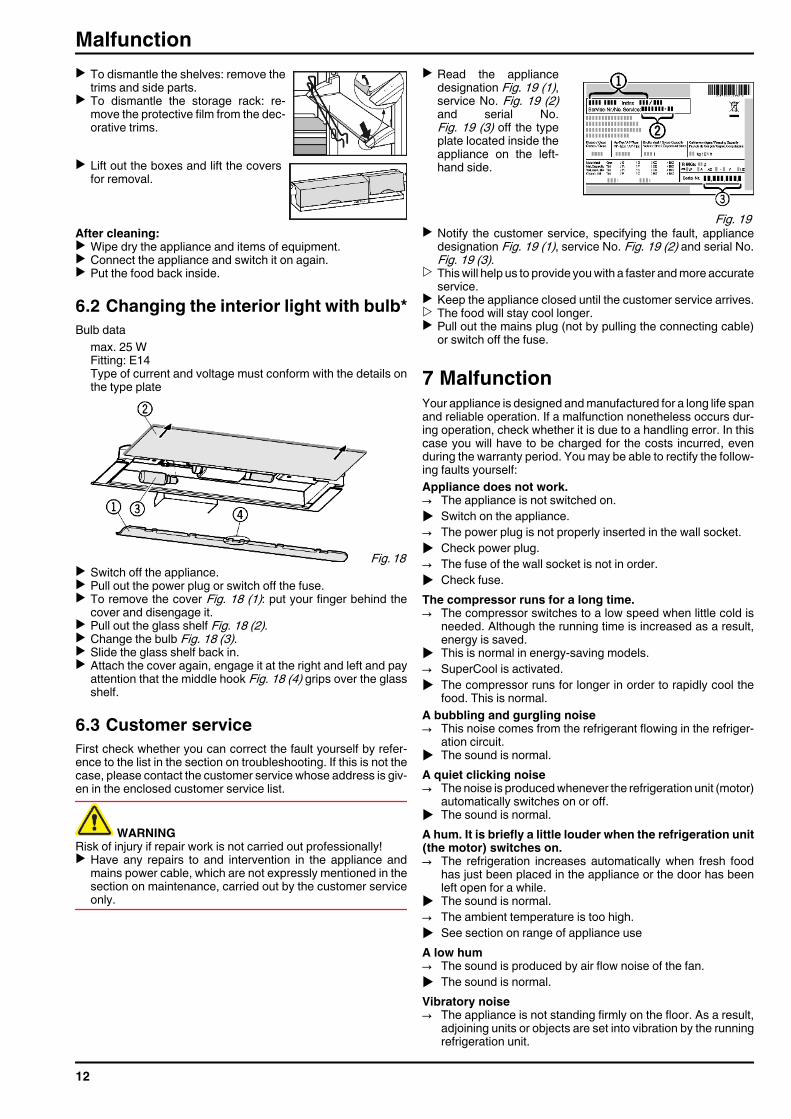
6.2 Changing the interior light with bulb*Bulb data
max. 25 WFitting: E14Type of current and voltage must conform with the details onthe type plate
Fig. 18 u Switch off the appliance.u Pull out the power plug or switch off the fuse.u To remove the cover Fig. 18 (1): put your finger behind the
cover and disengage it.u Pull out the glass shelf Fig. 18 (2).u Change the bulb Fig. 18 (3).u Slide the glass shelf back in.u Attach the cover again, engage it at the right and left and pay
attention that the middle hook Fig. 18 (4) grips over the glassshelf.
6.3 Customer serviceFirst check whether you can correct the fault yourself by refer-ence to the list in the section on troubleshooting. If this is not thecase, please contact the customer service whose address is giv-en in the enclosed customer service list.
WARNINGRisk of injury if repair work is not carried out professionally!u Have any repairs to and intervention in the appliance and
mains power cable, which are not expressly mentioned in thesection on maintenance, carried out by the customer serviceonly.
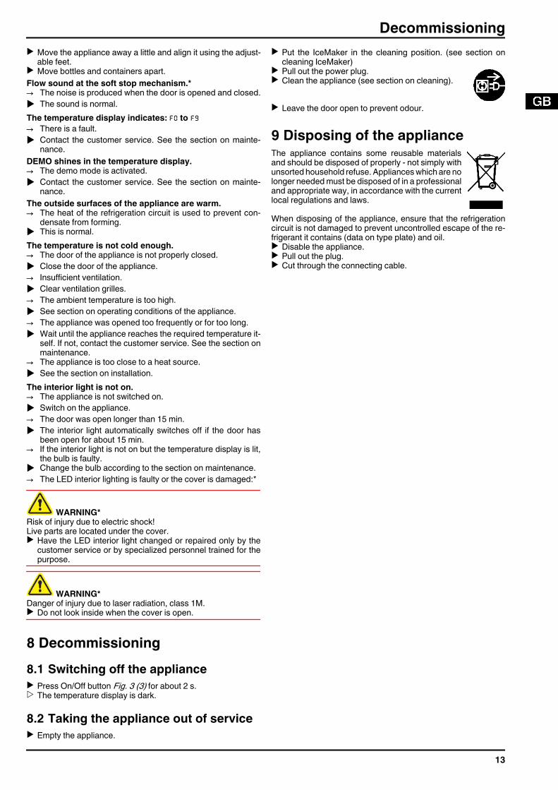
u Read the appliancedesignation Fig. 19 (1),service No. Fig. 19 (2)and serial No.Fig. 19 (3) off the typeplate located inside theappliance on the left-hand side.
Fig. 19 u Notify the customer service, specifying the fault, appliance
designation Fig. 19 (1), service No. Fig. 19 (2) and serial No.Fig. 19 (3).
w This will help us to provide you with a faster and more accurateservice.
u Keep the appliance closed until the customer service arrives.w The food will stay cool longer.u Pull out the mains plug (not by pulling the connecting cable)
or switch off the fuse.
7 MalfunctionYour appliance is designed and manufactured for a long life spanand reliable operation. If a malfunction nonetheless occurs dur-ing operation, check whether it is due to a handling error. In thiscase you will have to be charged for the costs incurred, evenduring the warranty period. You may be able to rectify the follow-ing faults yourself:Appliance does not work.→ The appliance is not switched on.u Switch on the appliance.→ The power plug is not properly inserted in the wall socket.u Check power plug.→ The fuse of the wall socket is not in order.u Check fuse.The compressor runs for a long time.→ The compressor switches to a low speed when little cold is
needed. Although the running time is increased as a result,energy is saved.
u This is normal in energy-saving models.→ SuperCool is activated.u The compressor runs for longer in order to rapidly cool the
food. This is normal.A bubbling and gurgling noise→ This noise comes from the refrigerant flowing in the refriger-
ation circuit.u The sound is normal.A quiet clicking noise→ The noise is produced whenever the refrigeration unit (motor)
automatically switches on or off.u The sound is normal.A hum. It is briefly a little louder when the refrigeration unit(the motor) switches on.→ The refrigeration increases automatically when fresh food
has just been placed in the appliance or the door has beenleft open for a while.
u The sound is normal.→ The ambient temperature is too high.u See section on range of appliance useA low hum→ The sound is produced by air flow noise of the fan.u The sound is normal.Vibratory noise→ The appliance is not standing firmly on the floor. As a result,
adjoining units or objects are set into vibration by the runningrefrigeration unit.
Malfunction
12
u Move the appliance away a little and align it using the adjust-able feet.
u Move bottles and containers apart.Flow sound at the soft stop mechanism.*→ The noise is produced when the door is opened and closed.u The sound is normal.The temperature display indicates: F0 to F9→ There is a fault.u Contact the customer service. See the section on mainte-
nance.DEMO shines in the temperature display.→ The demo mode is activated.u Contact the customer service. See the section on mainte-
nance.The outside surfaces of the appliance are warm.→ The heat of the refrigeration circuit is used to prevent con-
densate from forming.u This is normal.The temperature is not cold enough.→ The door of the appliance is not properly closed.u Close the door of the appliance.→ Insufficient ventilation.u Clear ventilation grilles.→ The ambient temperature is too high.u See section on operating conditions of the appliance.→ The appliance was opened too frequently or for too long.u Wait until the appliance reaches the required temperature it-
self. If not, contact the customer service. See the section onmaintenance.
→ The appliance is too close to a heat source.u See the section on installation.The interior light is not on.→ The appliance is not switched on.u Switch on the appliance.→ The door was open longer than 15 min.u The interior light automatically switches off if the door has
been open for about 15 min.→ If the interior light is not on but the temperature display is lit,
the bulb is faulty.u Change the bulb according to the section on maintenance.→ The LED interior lighting is faulty or the cover is damaged:*
WARNING*Risk of injury due to electric shock!Live parts are located under the cover.u Have the LED interior light changed or repaired only by the
customer service or by specialized personnel trained for thepurpose.
WARNING*Danger of injury due to laser radiation, class 1M.u Do not look inside when the cover is open.
8 Decommissioning8.1 Switching off the applianceu Press On/Off button Fig. 3 (3) for about 2 s.w The temperature display is dark.
8.2 Taking the appliance out of serviceu Empty the appliance.
u Put the IceMaker in the cleaning position. (see section oncleaning IceMaker)
u Pull out the power plug.u Clean the appliance (see section on cleaning).
u Leave the door open to prevent odour.
9 Disposing of the applianceThe appliance contains some reusable materialsand should be disposed of properly - not simply withunsorted household refuse. Appliances which are nolonger needed must be disposed of in a professionaland appropriate way, in accordance with the currentlocal regulations and laws.When disposing of the appliance, ensure that the refrigerationcircuit is not damaged to prevent uncontrolled escape of the re-frigerant it contains (data on type plate) and oil.u Disable the appliance.u Pull out the plug.u Cut through the connecting cable.
Decommissioning
13
Disposing of the appliance
14