Embed Size (px)
Citation preview
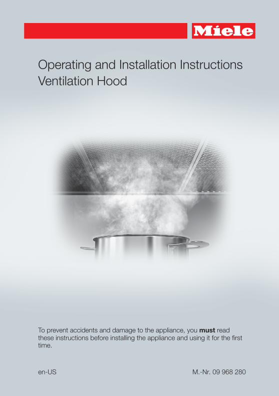
Operating and Installation InstructionsVentilation Hood
To prevent accidents and damage to the appliance, you must readthese instructions before installing the appliance and using it for the firsttime.
en-US M.-Nr. 09 968 280
Contents
2
IMPORTANT SAFETY INSTRUCTIONS ................................................................. 3
Caring for the environment ................................................................................. 12
Description of functions ...................................................................................... 13
Guide to the appliance......................................................................................... 14
Operation .............................................................................................................. 16Turning on the fan .................................................................................................. 16Selecting the power level....................................................................................... 16Turning off the fan .................................................................................................. 17Turning cooktop lighting On/Off............................................................................. 17Automatic safety shut-down.................................................................................. 17
Cleaning and care ................................................................................................ 18Stainless steel housing .......................................................................................... 18
Special instructions for glass surfaces ............................................................. 19Grease filter............................................................................................................ 19OdorFree Charcoal Filter........................................................................................ 21
Disposing of the OdorFree Charcoal Filter........................................................ 21Changing a light bulb............................................................................................. 22
Installation ............................................................................................................ 23Before installation .................................................................................................. 23Removing the protective film ................................................................................. 23Installation Instructions .......................................................................................... 23Disassembly........................................................................................................... 23Installation parts..................................................................................................... 24Appliance dimensions............................................................................................ 26Distance between cooktop and ventilation hood (S) ............................................. 28Installation recommendations................................................................................ 29Drilling diagram for wall mounting ......................................................................... 29
Exhaust duct......................................................................................................... 30Condensate trap .................................................................................................... 31Reducing Collar .................................................................................................... 31
Electrical connection ........................................................................................... 32
Service and warranty ........................................................................................... 33Location of the data plate ...................................................................................... 33
Technical data ..................................................................................................... 34
IMPORTANT SAFETY INSTRUCTIONS
3
READ AND SAVE THESE INSTRUCTIONS
This appliance complies with current safety requirements.Improper use of the appliance can lead to personal injury andmaterial damage.
Read all instructions before installing or using the appliance forthe first time. Only use the appliance for its intended purpose.
Keep these operating instructions in a safe place and pass themon to any future user.
Use
CAUTION: For General Ventilating Use Only. Do Not Use ToExhaust Hazardous Or Explosive Materials And Vapors.
This appliance is intended for residential use only. Use only asdescribed in these operating instructions.
This ventilation hood is not intended for outdoor use.
It must only be used to extract and clean vapors produced duringcooking. Any other use occurs at the owner's own risk.
This appliance is suitable for installation above gas or electriccooking surfaces.
Persons who lack physical, sensory or mental abilities, orexperience with the appliance should not use it without supervisionor instruction by a responsible person.
IMPORTANT SAFETY INSTRUCTIONS
4
Children
As with any appliance, close supervision is necessary when usedby children.
Please supervise children in the vicinity of the hood and do not letthem play with it.
Danger of suffocation! Ensure that any plastic wrappings, bags,etc. are disposed of safely and kept out of the reach of children.
Technical safety
WARNING: TO REDUCE THE RISK OF FIRE, ELECTRIC SHOCK,OR INJURY TO PERSONS, OBSERVE THE FOLLOWING:
– Use this appliance only in the manner intended by themanufacturer. If you have questions, contact Miele.
– Before servicing or cleaning the appliance, switch power off atthe service panel and lock the service disconnecting means toprevent power from being switched on accidentally. If the servicedisconnecting means cannot be locked, securely fasten aprominent warning device, such as a tag, to the service panel.
Installation, repair and maintenance work should be performed bya Miele authorized service technician in accordance with nationaland local safety regulations and the provided installationinstructions. Contact Miele’s Technical Service Department forexamination, repair or adjustment. Repairs and other work byunauthorized persons could be dangerous and may void thewarranty.
A damaged ventilation hood oven can be dangerous. Alwayscheck for visible signs of damage. Never use a damaged ventilationhood.
IMPORTANT SAFETY INSTRUCTIONS
5
Be certain your appliance is properly installed and grounded by aqualified technician. To guarantee the electrical safety of thisappliance, continuity must exist between the appliance and aneffective grounding system. It is imperative that this basic safetyrequirement be met. If there is any doubt, have the electrical systemof the house checked by a qualified electrician.
To avoid damaging the ventilation hood, make sure that theconnection data (voltage and frequency) on the data platecorrespond to the building's power supply before connecting theappliance. When in doubt, consult a qualified electrician.
Do not use a power bar or extension cord to connect theventilation hood to electricity. These are a fire hazard and do notguarantee the required level of appliance safety.
To ensure safe operation, only use the ventilation hood after it hasbeen properly installed.
This ventilation hood may not be used in non-stationary locations(e.g. on a ship).
Only open the housing as described in the enclosed "Installationdiagram" and in the "Cleaning and care" section of this manual.Under no circumstances should any other parts of the housing beopened.Tampering with electrical connections or components andmechanical parts is highly dangerous to the user and can causeoperation faults.
IMPORTANT SAFETY INSTRUCTIONS
6
Defective components should be replaced by Miele original partsonly. Only with these parts can the manufacturer guarantee thesafety of the appliance.
If the power cord is damaged, it must only be replaced by aqualified service technician.
During installation, maintenance, and repair work, the ventilationhood must be disconnected from the electrical supply. It is onlycompletely isolated from the electricity supply if one of the followingapplies:
– The circuit breakers on the electrical service panel are tripped.
– The screw-type fuses on the electrical service panel have beenremoved.
– The power cable (if present) has been unplugged from the socket(pull the plug not the cord).
Proper use
WARNING: TO REDUCE THE RISK OF A COOKTOP GREASEFIRE:
– a) Never leave surface units unattended at high settings.Boilovers cause smoking and greasy spillovers may ignite. Heatoils slowly on low or medium settings.
– b) Always turn the hood on when cooking at a high heat.
– c) Clean the ventilation hood frequently. Grease should not beallowed to accumulate on the fan or filter.
– d) Use the proper pan size. Always use cookware appropriate forthe size of the cooking area.
Never use an open flame beneath the ventilation hood.To avoid the risk of fire, do not flambé or grill over an open flame.When turned on, the ventilation hood will draw any flames into thefilter. Fat deposits may ignite.
IMPORTANT SAFETY INSTRUCTIONS
7
WARNING: TO REDUCE THE RISK OF INJURY TO PERSONS INTHE EVENT OF A COOKTOP GREASE FIRE, OBSERVE THEFOLLOWING*:
– a) SMOTHER FLAMES with a close fitting lid, cookie sheet, ormetal tray then turn off the burner. BE CAREFUL TO PREVENTBURNS. If the flames do not go out immediately, EVACUATE ANDCALL THE FIRE DEPARTMENT.
– b) NEVER PICK UP A FLAMING PAN - You may be burned.
– c) DO NOT USE WATER, including wet dishcloths or towels - aviolent steam explosion will result.
– d) Use a fire extinguisher ONLY if:– 1) You have a class ABC extinguisher, and you know how to operate it.
– 2) The fire is small and contained in the area where it started.
– 3) The fire department is being called.
– 4) You can fight the fire with your back to an exit.
*Based on "Kitchen Firesafety Tips" published by NFPA.
The ventilation hood may become damaged if exposed toexcessive heat from a gas cooktop.
– When using the ventilation hood over a gas cooktop, ensure thatany burners in use are always covered by cookware. Turn burnersoff when removing the cookware, even if doing so for just a shorttime.
– Select cookware that is suitable for the size of the burner.
– Adjust the flame so that it never extends up the sides of thecookware.
– Avoid overheating the cookware (e.g., when cooking with a wok).
Always turn the ventilation hood on whenever a burner is in use toprevent damage from condensation.
IMPORTANT SAFETY INSTRUCTIONS
8
Overheated oils and fats can ignite and set the ventilation hoodon fire.When cooking with oils or fats, do not leave pots, pans or fryersunattended. Never leave an electric grill unattended when grilling.
Fat and debris deposits impair the proper functioning of theventilation hood.To ensure that cooking vapors are properly cleaned, never use theventilation hood without the grease filters in place.
A filter containing too much grease is a fire hazard!The filters should be cleaned or replaced at regular intervals.
Please note that the heat rising from the stovetop during cookingcan cause the ventilation hood to become very hot.Do not touch the housing or the grease filters until the ventilationhood has cooled down.
IMPORTANT SAFETY INSTRUCTIONS
9
Proper installation
WARNING: TO REDUCE THE RISK OF FIRE, ELECTRIC SHOCK,OR INJURY TO PERSONS, OBSERVE THE FOLLOWING:
– a) Installation work and electrical wiring must be done byqualified person(s) in accordance with all applicable codes andstandards, including fire-rated construction.
– b) Sufficient air is needed for combustion and exhausting ofgases through the flue (chimney of fuel burning equipment toprevent back drafting. Follow the heating equipmentmanufacturer’s guideline and safety standards such as thosepublished by the National Fire Protection Association (NFPA) andthe American Society for Heating, Refrigeration and AirConditioning Engineers (ASHRAE), and the local code authorities.
– c) When cutting or drilling into the wall or ceiling, do not damageelectrical wiring and other hidden utilities.
– d) Ducted hoods must always be vented to the outdoors.
– e) Do not use this hood with any solid-state speed control device.
To determine whether a ventilation hood may be operated aboveyour cooking appliance, please refer to the information provided bythe appliance's manufacturer.
Safety regulations prohibit the installation of a ventilation hoodabove solid fuel stoves.
Insufficient distance between the cooking appliance and theventilation hood can result in damage to the hood.The minimum safety distances between the appliance and thebottom of the ventilation hood specified in the "Installation" sectionmust be maintained, unless the appliance's manufacturer hasindicated that a greater distance is required.If more than one cooking appliance is used beneath the ventilationhood, and if different minimum safety distances apply for theseappliances, you should use the greater distance.
IMPORTANT SAFETY INSTRUCTIONS
10
Be sure to observe the information contained in the "Installation"section when mounting the ventilation hood.
When installing the exhaust duct, only use pipes or tubes made ofnon-flammable material. These can be obtained from your Mieledealer or from Miele Technical Service.
Exhaust air should not be vented into a chimney or vent fluewhich is otherwise in use and should not be channeled into ductingwhich ventilates rooms with fuel-burning installations.
If exhaust air is to be extracted into a chimney or vent flue nolonger used for other purposes, be sure to comply with all applicableregulations.
WARNING: TO REDUCE THE RISK OF FIRE USE ONLY METALDUCTWORK.
IMPORTANT SAFETY INSTRUCTIONS
11
Cleaning and care
Never use a steam cleaner to clean the ventilation hood.The steam can reach the electrical components and cause a shortcircuit.
Accessories
Use only genuine original Miele parts. If parts or accessories fromother manufacturers are used, the warranty will become void.
Caring for the environment
12
Disposal of the packingmaterialThe cardboard box and packingmaterials protect the appliance duringshipping. They have been designed tobe biodegradable and recyclable.
Ensure that any plastic wrappings,bags, etc. are disposed of safely andkept out of the reach of children.Danger of suffocation!
Disposal of your old applianceDo not dispose of this appliance withyour household waste.
Old appliances may contain materialsthat can be recycled. Please contactyour local recycling authority about thepossibility of recycling these materials.
Before discarding an old applianceensure that it presents no danger tochildren while being stored for disposal.Unplug it from the outlet, cut off itspower cord and remove any doors toprevent hazards.
Description of functions
13
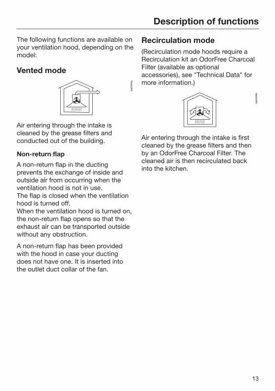
The following functions are available onyour ventilation hood, depending on themodel:
Vented mode
Air entering through the intake iscleaned by the grease filters andconducted out of the building.
Non-return flap
A non-return flap in the ductingprevents the exchange of inside andoutside air from occurring when theventilation hood is not in use.The flap is closed when the ventilationhood is turned off.When the ventilation hood is turned on,the non-return flap opens so that theexhaust air can be transported outsidewithout any obstruction.
A non-return flap has been providedwith the hood in case your ductingdoes not have one. It is inserted intothe outlet duct collar of the fan.
Recirculation mode(Recirculation mode hoods require aRecirculation kit an OdorFree CharcoalFilter (available as optionalaccessories), see "Technical Data" formore information.)
Air entering through the intake is firstcleaned by the grease filters and thenby an OdorFree Charcoal Filter. Thecleaned air is then recirculated backinto the kitchen.
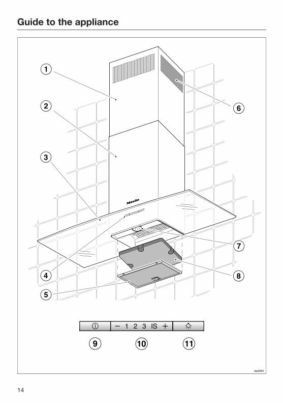
Guide to the appliance
14
Guide to the appliance
15
a Chimney extension
b Chimney
c Canopy
d Control panel
e Grease filter
f Recirculation vent(only for recirculation mode)
g Cooktop lighting
h OdorFree Charcoal FilterOptional accessory for recirculation mode
i On/Off button for fan
j Buttons for setting the fan power
k On/Off button for the cooktop lighting
Operation
16
Turning on the fan Press the On/Off button .
The fan turns on at level 2. The symbol and 2 will light up in the fanlevel display.
Selecting the power levelPower levels 1 to 3 can be used for lightto heavy cooking vapors and odors.
For strong vapors and odors that aretemporarily produced when cooking,e.g. during searing, select the IS levelas an intensive setting.
Press the "" button for a lowerpower level or the "" button toselect a higher level.
Automatically switching backfrom the intensive level (IS)The intensive level can be programmedto switch back to level 3 automaticallyafter 10 minutes.
To do so, turn off the fan and thecooktop lighting.
Press the and buttons at thesame time for approx. 10 seconds,until 1 lights up.
Then, press the following buttons inorder:
– The lighting button ,
– Followed by the button and then
– The lighting button again.
If automatic switch-off is not activated,the 1 and IS displays will flash.
To activate it, press the button.
If 1 and IS are lit up, automatic switch-off is activated.
To deactivate it, press the button.
Use the On/Off control to confirmyour choice of setting.If you do not confirm within 4minutes, the hood will revert to theold setting.
Operation
17
Turning off the fan Press the On/Off button to turn the
fan off.
The symbol will go out.
Turning cooktop lightingOn/OffThe cooktop lighting can be turned onand off separately from the fan.
To do so, press the button.
The symbol is lit when the cooktoplighting is turned on.
Automatic safety shut-downShould the hood be left on, the fan willswitch off automatically after 10 hours.The lighting will remain on.
Pressing the On/Off button willswitch the fan back on again.
Cleaning and care
18
WARNING: TO REDUCE THE RISKOF FIRE, ELECTRIC SHOCK, ORINJURY TO PERSONS, OBSERVETHE FOLLOWING:
Before cleaning or servicing thehood, disconnect it from the powersupply.
Stainless steel housing
General
The surfaces and control buttons aresusceptible to scratching andchipping.Observe the following cleaninginstructions.
Clean all surfaces and controlbuttons using warm water and liquiddish soap only, applying the mixturewith a sponge cloth.
Make sure that no water gets intothe interior of the hood.Only use a damp cloth to clean thehood, especially in the control panelarea.
After cleaning, dry the surfaces with asoft cloth.
Avoid the following:
– Cleaners containing soda, acid orchloride, or cleaners containingsolvents
– Abrasive cleaners such as scouringpowder, scouring liquid, abrasivesponges such as pot scourers, orused sponges that still containresidues from abrasive cleaners
Special instructions for stainlesssteel surfaces
(does not apply to control buttons)
Stainless steel surfaces can also becleaned using a non-abrasivestainless steel cleaner, available fromMiele.
To prevent the surfaces from quicklybecoming dirty again, werecommend treating them with astainless steel care conditioner.Apply sparingly over the entire areausing a soft cloth.
Special instructions for RAL colorfinish housing
(special order)
Observe the general cleaninginstructions contained in this chapter.
Minor scratches on the surface areinevitable when cleaning the housing.Depending on the lighting in thekitchen, this may negatively affect theappliance's appearance.
Cleaning and care
19
Special instructions for controlbuttons
Do not leave dirt and debris on thebuttons for any length of time.Otherwise they may becomediscolored or damaged.Remove any dirt or debrisimmediately.
Observe the general cleaninginstructions contained in this chapter.
Do not use a stainless steel cleanerto clean the control buttons.
Special instructions for glasssurfaces
Glass surfaces can be cleaned usinga commercial glass cleaner.
Grease filterThe reusable metal grease filter in theappliance removes solid particles fromthe kitchen vapors (grease, dust, etc.)preventing soiling of the hood.
A dirty filter is a fire hazard!
Cleaning intervals
Over longer periods of time, fat buildupon the grease filter hardens and makescleaning more difficult. Therefore, werecommend cleaning the grease filtersonce every 3-4 weeks.
Removing the grease filters
The area around the filter will getvery hot due to heat from thecooktop lighting.Danger of burns!Switch the cooktop lighting off andwait a few minutes after cooking forthe hood to cool down beforeremoving the filter.
When handling a grease filter, becareful not to drop it.This can result in damage to the filterand to the cooktop.Make sure you hold the filtersecurely at all times when handlingit.
Cleaning and care
20
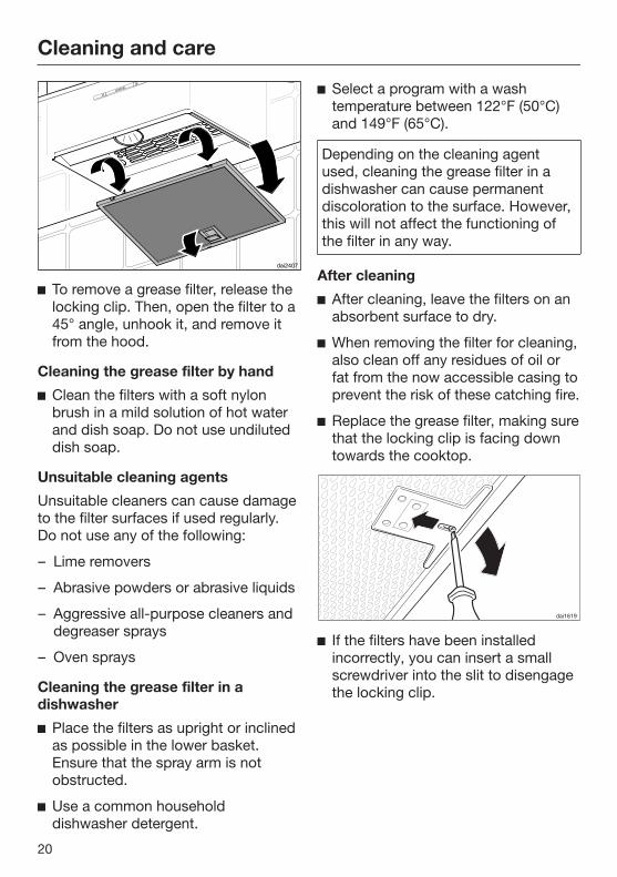
To remove a grease filter, release thelocking clip. Then, open the filter to a45° angle, unhook it, and remove itfrom the hood.
Cleaning the grease filter by hand
Clean the filters with a soft nylonbrush in a mild solution of hot waterand dish soap. Do not use undiluteddish soap.
Unsuitable cleaning agents
Unsuitable cleaners can cause damageto the filter surfaces if used regularly.Do not use any of the following:
– Lime removers
– Abrasive powders or abrasive liquids
– Aggressive all-purpose cleaners anddegreaser sprays
– Oven sprays
Cleaning the grease filter in adishwasher
Place the filters as upright or inclinedas possible in the lower basket.Ensure that the spray arm is notobstructed.
Use a common householddishwasher detergent.
Select a program with a washtemperature between 122°F (50°C)and 149°F (65°C).
Depending on the cleaning agentused, cleaning the grease filter in adishwasher can cause permanentdiscoloration to the surface. However,this will not affect the functioning ofthe filter in any way.
After cleaning
After cleaning, leave the filters on anabsorbent surface to dry.
When removing the filter for cleaning,also clean off any residues of oil orfat from the now accessible casing toprevent the risk of these catching fire.
Replace the grease filter, making surethat the locking clip is facing downtowards the cooktop.
If the filters have been installedincorrectly, you can insert a smallscrewdriver into the slit to disengagethe locking clip.
Cleaning and care
21
OdorFree Charcoal FilterIf the hood is connected forrecirculation, an OdorFree CharcoalFilter must be inserted in addition to thegrease filter. This is designed to absorbcooking odors. It is fitted in the canopy above thegrease filter.
OdorFree Charcoal Filters are availablefrom your Miele dealer or from MieleService. See "Technical data" for thetype and reference number.
Installing/replacing the OdorFreeCharcoal Filter
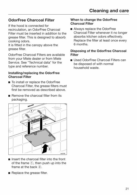
To install or replace the OdorFreeCharcoal Filter, the grease filters mustfirst be removed as described above.
Remove the charcoal filter from itspackaging.
Insert the charcoal filter into the frontof the frame , then push up into theframe at the back .
Replace the grease filter.
When to change the OdorFreeCharcoal Filter
Always replace the OdorFreeCharcoal Filter whenever it no longerabsorbs kitchen odors effectively.Replace the filter at least once every6 months.
Disposing of the OdorFree CharcoalFilter
Used OdorFree Charcoal Filters canbe disposed of with normalhousehold waste.
Cleaning and care
22
Changing a light bulb
The halogen lights become very hotwhen in use.They can cause burns even afterbeing shut off for some time.Allow them to cool down for a fewminutes before changing them.
Disconnect the hood from theelectrical supply before replacing thelights (see "IMPORTANT SAFETYINSTRUCITONS").
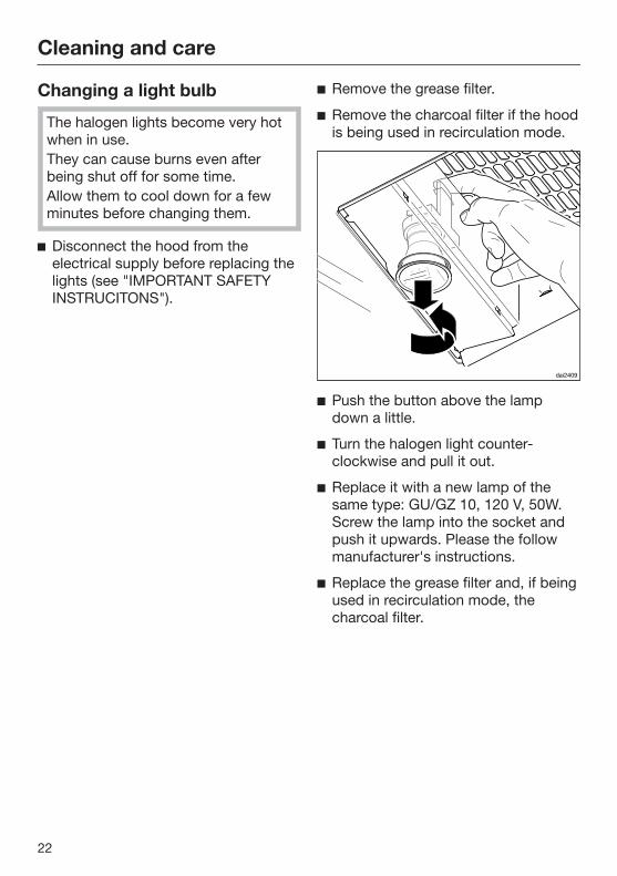
Remove the grease filter.
Remove the charcoal filter if the hoodis being used in recirculation mode.
Push the button above the lampdown a little.
Turn the halogen light counter-clockwise and pull it out.
Replace it with a new lamp of thesame type: GU/GZ 10, 120 V, 50W.Screw the lamp into the socket andpush it upwards. Please the followmanufacturer's instructions.
Replace the grease filter and, if beingused in recirculation mode, thecharcoal filter.
Installation
23
Before installation
Before installing the appliance,read all of the information containedin this chapter and also in the"IMPORTANT SAFETYINSTRUCTIONS" section.
Removing the protective filmThe housing components are coveredby a protective film to prevent themfrom becoming damaged duringtransport.
Please remove this film beforeinstalling the housing components. Itcan be peeled off easily without anyadditional tools.
Installation InstructionsPlease refer to the accompanyinginstallation sheet for instructions onhow to install the appliance.
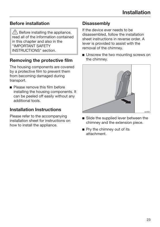
DisassemblyIf the device ever needs to bedisassembled, follow the installationsheet instructions in reverse order. Alever is provided to assist with theremoval of the chimney.
Unscrew the two mounting screws onthe chimney.
Slide the supplied lever between thechimney and the extension piece.
Pry the chimney out of itsattachment.
Installation
24
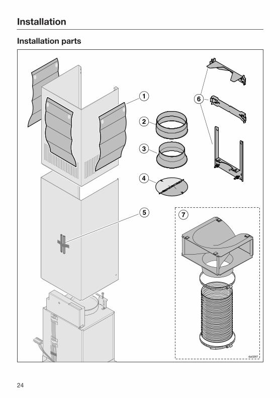
Installation parts
Installation
25
a 3 protective installation sheetsfor use when installing the chimney
b 1 exhaust connectorfor an exhaust duct 6" (150 mm).
c 1 reducerfor an exhaust duct 5" (125 mm).
d 1 non-return flapfor installation in the outlet ductcollar of the motor unit (not forrecirculation mode). Depending onthe device version, the non-returnflap is already mounted.
e 2 protective spacersfor use when fitting the chimney.
f Wall bracketfor securing the hood on the wall.
g Recirculation kit for recirculationmodecontains diverter, aluminum hoseand hose clamps (not contained inscope of delivery, available asoptional accessory – see "TechnicalData").
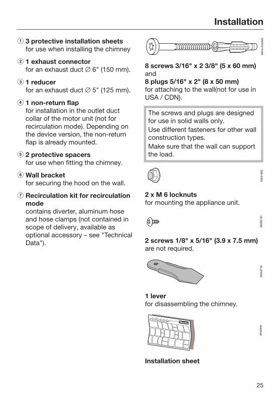
8 screws 3/16" x 2 3/8" (5 x 60 mm)and8 plugs 5/16" x 2" (8 x 50 mm)for attaching to the wall(not for use inUSA / CDN).
The screws and plugs are designedfor use in solid walls only.Use different fasteners for other wallconstruction types.Make sure that the wall can supportthe load.
2 x M 6 locknutsfor mounting the appliance unit.
2 screws 1/8" x 5/16" (3.9 x 7.5 mm)are not required.
1 leverfor disassembling the chimney.
Montage
Installation
Montaje
M
ontaggio
Montering
Montagem
A
sennus
Installation sheet
Installation
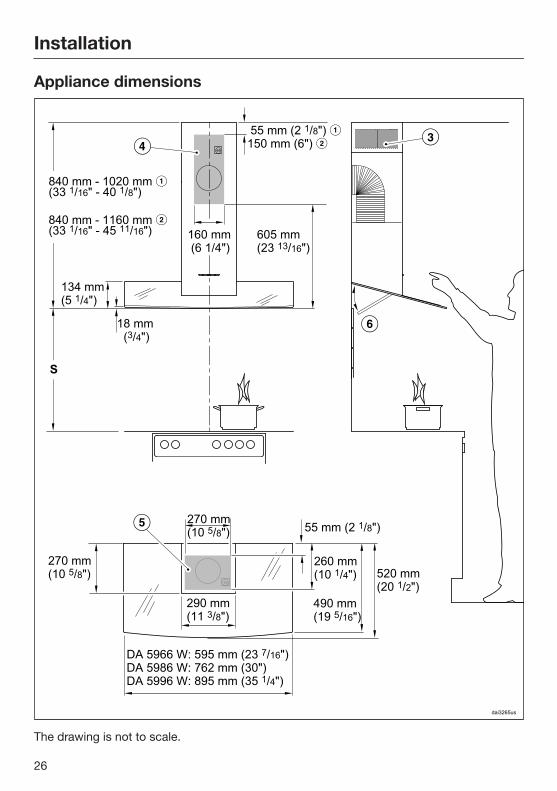
26
Appliance dimensions
The drawing is not to scale.
Installation
27
a Vented
b Recirculation
c Air outlet positioned at top for recirculation
de (only d is required for recirculation mode hoods): The shaded arearepresents the wall or ceiling area for the vent cut-out, for fitting theconnection socket and on EXT models for feeding the connection cablethrough to the external motor. Recirculation mode range hoods only requirean electrical connection socket.
Existing tiling or a back panel behind the hood can make it difficult to removethe grease filter. If this is the case, turn the filter by 180° and fit it before the rangehood is installed . Exhaust connector 6" (150 mm), with reducer 5" (125 mm).
Installation
28
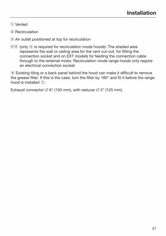
Distance between cooktop and ventilation hood (S)
Provided a larger distance is not given by the manufacturer of the cooktop,follow the minimum safety distances between a cooktop and the bottom of thehood.Please also observe the information contained in the "IMPORTANT SAFETYINSTRUCTIONS" section.
Minimum distance S
Cooking appliance Mieleappliance
Non-Mieleappliance
Electric/Induction cooktop 24" (610 mm)
Electric grill, deep fat fryer (electric) 26" (660 mm)
Multi-burner gas cooktop ≤ 43,000 BTU/hr (12.6 W), no burner > 15,000 BTU/hr (4.5 kW).
26" (660 mm) 30" (760 mm)
Multi-burner gas cooktop ≤ 73,800 BTU/hr (21.6 W), no burner > 16,500 BTU/hr (4.8 kW)
30" (760 mm)
Multi-burner gas cooktop > 73,800 BTU/hr (21.6 W), or one of the burners > 16,500 BTU/hr (4.8 kW)
Not possible
Single-burner gas cooktop ≤ 20,500 BTU/hr (6 kW)
26" (660 mm) 30" (760 mm)
Single-burner gas cooktop ≤ 27,600 BTU/hr (8.1 kW)
30" (760 mm)
Single-burner gas cooktop > 27,600 BTU/hr (8.1 kW)
Not possible
Installation
29
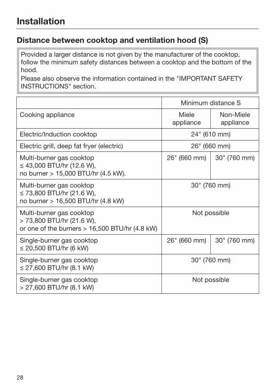
Installation recommendations– We also recommend a distance of at
least 25 1/2" (650 mm) above electriccooktops to provide more workspaceand easier cooking under the hood.
– When selecting an installation height,always take the user height intoconsideration. Users should haveample space to work comfortably onthe cooktop and reach the ventilationhood controls with ease.
– Please note that the greater thedistance from the cooktop, the lesseffective the hood is at drawing in thecooking vapors.
– To achieve optimal vapor extraction,make sure that the hood covers thecooktop. The hood should bepositioned centrally over thecooktop, not to the side or rear.
– The cooktop should be no wider thanthe hood. Preferably, it should benarrower.
– The mounting area must be easilyaccessible. The ventilation hoodshould be easy to reach anddisassemble in case a service call isnecessary. This should be taken intoconsideration when planning theposition of cupboards, shelves,ceilings or decorative elements in thevicinity of the ventilation hood.
Drilling diagram for wallmounting When drilling, please follow the
directions contained on theaccompanying installation sheet.
When installing a custom back wallwith pre-drilled holes, please refer tothe drilling distances in the drawingabove (screws 3/16" (5 mm)).
* The dimension for the middle wallbracket is variable. It will depend on theposition of the wall vent and the socket.It should be set as low as possible.
Exhaust duct
30
WARNING: Danger of toxic fumes.Gas cooking appliances releasecarbon monoxide that can beharmful or fatal if inhaled.To reduce the risk of fire and toproperly exhaust air, the exhaustgases extracted by the hood shouldbe vented outside of the buildingonly.Do not vent exhaust air into spaceswithin walls or ceilings or in attics,crawl spaces or garages.To reduce the risk of fire, only usemetal ductwork.Please read and follow the"IMPORTANT SAFETYINSTRUCTIONS" to reduce the riskof personal injury. Follow all localbuilding codes when installing thehood.
Only use smooth pipes or flexibleduct hoses made from non-flammable materials for exhaustductwork.
To achieve the greatest possible airextraction with the lowest noiselevels, please note the following:
– The diameter of the exhaust ductshould not be less than 6" (150 mm).
– If flat exhaust ducts are used, thecross section should not be smallerthan that of the exhaust connector.
– The exhaust duct should be as shortand straight as possible.
– If elbows are needed, make sure theyhave a large radius.
– The exhaust duct itself must not bekinked or compressed.
– Make sure that all connections aresecure and airtight.
Remember that any constriction ofthe airflow will reduce extractionperformance and increase operatingnoise.
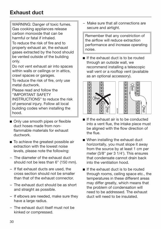
If the exhaust duct is to be routedthrough an outside wall, werecommend installing a telescopicwall vent or a rooftop vent (availableas an optional accessory).
If the exhaust air is to be conductedinto a vent flue, the intake piece mustbe aligned with the flow direction ofthe flue.
When installing the exhaust ducthorizontally, you must slope it awayfrom the source by at least 1 cm permeter (3/8" per 3 1/4'). This ensuresthat condensate cannot drain backinto the ventilation hood.
If the exhaust duct is to be routedthrough rooms, ceiling space etc., thetemperatures in these different areasmay differ greatly, which means thatthe problem of condensation willneed to be addressed. The exhaustduct will need to be insulated.
Exhaust duct
31
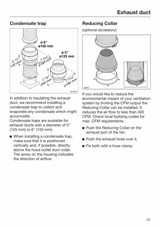
Condensate trap
In addition to insulating the exhaustduct, we recommend installing acondensate trap to collect andevaporate any condensate which mightaccumulate.Condensate traps are available forexhaust ducts with a diameter of 5"(125 mm) or 6" (150 mm).
When installing a condensate trap,make sure that it is positionedvertically and, if possible, directlyabove the hood outlet duct collar.The arrow on the housing indicatesthe direction of airflow.
Reducing Collar(optional accessory)
If you would like to reduce theenvironmental impact of your ventilationsystem by limiting the CFM output theReducing Collar can be installed. Itreduces the air flow to less than 400CFM. Check local building codes formax. CFM requirements.
Push the Reducing Collar on theexhaust port of the fan.
Push the exhaust hose over it.
Fix both with a hose clamp.
Electrical connection
32
WARNING: TO REDUCE THE RISKOF FIRE, ELECTRIC SHOCK, ORINJURY TO PERSONS, OBSERVETHE FOLLOWING:All electrical work should beperformed by a qualified electricianin strict accordance with nationalregulations (for USA: ANSI-NFPA 70)and local safety regulations.Installation, repairs and other workby unqualified persons could bedangerous.Ensure that power to the appliance isOFF while installation or repair workis performed.Verify that the voltage, load andcircuit rating information found onthe data plate (located behind thebaffle filters), match the householdelectrical supply before installing thehood.Use only with ventilation hood cord-connection kits that have beeninvestigated and found acceptablefor use with this model hood.If there is any question concerningthe electrical connection of thisappliance to your power supply,please consult a licensed electricianor call Miele’s Technical ServiceDepartment.
WARNING: THIS APPLIANCE MUSTBE GROUNDED
The hood comes equipped with apower cord with a NEMA 5-15 moldedplug for connection to a 120 VAC, 60Hz, 15 A power outlet.
Grounding Instructions
WARNING - Improper grounding canresult in a risk of electric shock.
This appliance must be grounded. Inthe event of an electrical short circuit,grounding reduces the risk of electricshock by providing a path of leastresistance. This appliance is equippedwith a cord having a grounding wirewith a grounding plug.
If there is any doubt, have the electricalsystem of the house checked by aqualified electrician.
Do not use an extension cord. If thepower supply cord is too short, have aqualified electrician install an outletnear the appliance.
The plug must be plugged into anoutlet that is properly installed andgrounded.
WARNING - Grounding instructions(Canada)The grounding-type attachment plugshall be connected to a grounding-type receptacle installed inaccordance with CSA C22.1-12,Canadian Electrical Code, Part I.
Service and warranty
33
For faults that you cannot resolve onyour own, please contact your Mieledealer or Miele Technical Service.
The telephone number for the TechnicalService Department is listed at the backof these instructions.
When contacting Miele, please statethe model and serial number of yourventilation hood.These can be found on the data plate.
Location of the data plateThe data plate is visible once you haveremoved the grease filters.
WarrantyFor further information, please refer toyour warranty booklet.
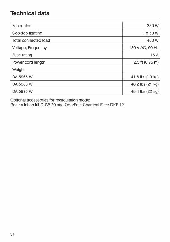
Technical data
34
Fan motor 350 W
Cooktop lighting 1 x 50 W
Total connected load 400 W
Voltage, Frequency 120 V AC, 60 Hz
Fuse rating 15 A
Power cord length 2.5 ft (0.75 m)
Weight
DA 5966 W 41.8 lbs (19 kg)
DA 5986 W 46.2 lbs (21 kg)
DA 5996 W 48.4 lbs (22 kg)
Optional accessories for recirculation mode:Recirculation kit DUW 20 and OdorFree Charcoal Filter DKF 12

9 Independence Way
Princeton, NJ 08540
Phone:
Fax:
www.mieleusa.com
U.S.A.Miele, Inc.
National Headquarters
Please have the model and serial numberof your appliance available beforecontacting Technical Service.
CanadaImporterMiele Limited
Headquarters and Miele Centre
800-843-7231
609-419-9898
609-419-4298
Technical Service & SupportNationwidePhone:
Fax:
161 Four Valley Drive
Vaughan, ON L4K 4V8
www.miele.ca
800-999-1360
888-586-8056
Customer Care CentrePhone:
800-565-6435
905-532-2272
GermanyManufacturerMiele & Cie. KG
Carl-Miele-Straße 29
33332 Gütersloh
35

M.-Nr. 09 968 280 / 01en-US
DA 5966 WDA 5986 WDA 5996 W