Embed Size (px)
Citation preview
La Péronnière BP9 – 42152 L’HORME – France ( 04 77 29 24 24 7 04 77 31 28 11
E.Mail: [email protected] Web: http://www.haulotte.com
OPERATING AND MAINTENANCE INSTRUCTIONS
SELF-PROPELLED ACCESS PLATFORMS HA15D - HA15DX
Cod
e : 0
1202
4203
1431
0
Issu
e : 0
2-00
Pinguely - Haulotte Operation and maintenance – HA15D / HA15DX
Page 2
You have just taken delivery of your PINGUELY-HAULOTTE self-propelled access platform. It will give you complete satisfaction if you follow the operating and maintenance instructions exactly. The purpose of this instruction manual is to help you in this. We stress the importance: • of complying with the safety instructions relating to the machine itself, its use and its environment, • of using it within the limits of its performances, • of proper maintenance upon which its service life depends. During and beyond the warranty period, our After-Sales Department is at your disposal for any service you might need. Contact in this case our Local Agent or our Factory After-Sales Department, specifying the exact type of machine and its serial number. When ordering consumables or spares, use this manual together with the “Spares” catalogue so as to receive original parts, the only guarantee of interchangeability and perfect operation. IMPORTANT : This instruction manual is supplied with the machine and is included on the delivery note.
You are reminded that our machines comply with the provisions of the “Machines Directive” 89/392/EEC of June 14th 1989 as amended by the directives 91/368/EEC of June 21st 1991, 93/44/CEE of June 14th 1993,
93/68/CEE of July 22nd 1993 and 89/336/EEC of May 3rd 1989.
ACCESS PLATFORM HA15D / HA15DX Ref. : 01202420314310
Issue E 02-00 The technical data contained in this manual cannot involve our responsibility and we reserve the right to proceed with improvements or modifications without amending this manual.
Operation and maintenance – HA15D / HA15DX Pinguely - Haulotte
Page 3
CONTENTS
1. GENERAL RECOMMENDATIONS – SAFETY 5
1.1 GENERAL WARNING .............................................................................................................................5 1.2 GENERAL SAFETY INSTRUCTIONS.....................................................................................................6 1.3 RESIDUAL RISKS ...................................................................................................................................7 1.4 OPERATING LIMITS ...............................................................................................................................7 1.5 VERIFICATIONS .....................................................................................................................................8
1.5.1 Routine verifications...........................................................................................................................8 1.5.2 Examination of suitability of a machine..............................................................................................8 1.5.3 State of conservation .........................................................................................................................8
1.6 REPAIRS AND ADJUSTMENTS.............................................................................................................8 1.7 VERIFICATIONS AT THE TIME OF PUTTING BACK INTO SERVICE..................................................8
2. PRESENTATION 9
2.1 IDENTIFICATION ....................................................................................................................................9 2.2 MAIN COMPONENTS ...........................................................................................................................10 2.3 WORK SPACE.......................................................................................................................................11 2.4 TECHNICAL CHARACTERISTICS........................................................................................................12 2.5 OVERALL DIMENSIONS.......................................................................................................................13
3. OPERATING PRINCIPLE. 14
3.1 HYDRAULIC CIRCUIT...........................................................................................................................14 3.1.1 Travel, turret rotation, arm lifting, boom raising, boom telescoping, platform compensation movements .......................................................................................................................................14 3.1.2 Direction movement. ........................................................................................................................14 3.1.3 Telescoping, boom raising, arm lifting cylinders. .............................................................................14 3.1.4 Turret rotation ..................................................................................................................................14 3.1.5 Platform compensation ....................................................................................................................14 3.1.6 Brake release of the wheel reducers when travelling ......................................................................14 3.1.7 Travel ...............................................................................................................................................15 3.1.8 Manual emergency and back-up system .........................................................................................15
3.2 ELECTRICAL CIRCUIT. ........................................................................................................................16 3.2.1 Automatic engine stop. ....................................................................................................................16 3.2.2 Platform load monitor. ......................................................................................................................16 3.2.3 5° angle monitor...............................................................................................................................16 3.2.4 High travel speed. ............................................................................................................................16 3.2.5 Hour counter: ...................................................................................................................................16
4. USING THE MACHINE 17
4.1 OPERATING SAFETY DEVICES ..........................................................................................................17 4.1.1 Movement (control from the “platform” post)....................................................................................17 4.1.2 Emergency or recovery procedure ..................................................................................................17
4.2 OFFLOADING – LOADING – MOVEMENT – PRECAUTIONS. ...........................................................18 4.2.1 Offloading by lifting ..........................................................................................................................18 4.2.2 Offloading with ramps ......................................................................................................................18 4.2.3 Loading ............................................................................................................................................19 4.2.4 Travel ...............................................................................................................................................19 4.2.5 Filling the fuel tank ...........................................................................................................................19
4.3 OPERATIONS BEFORE FIRST PUTTING INTO SERVICE.................................................................20 4.3.1 “Turret” control post: (photos 1 - 2) ..................................................................................................20 4.3.2 “Platform” control post: (photo 3) .....................................................................................................21 4.3.3 Checks before using the machine....................................................................................................21
4.4 PUTTING INTO SERVICE.....................................................................................................................23 4.4.1 Operations from the ground.............................................................................................................23 4.4.2 Operations from the platform: (photo 3)...........................................................................................23
4.5 EMERGENCY AND BACK-UP OPERATIONS......................................................................................25 4.5.1 Emergency assistance with the hand pump: (photo 8) ....................................................................25 4.5.2 Back-up : (photo 1) ..........................................................................................................................25
4.6 UNCOUPLING. ......................................................................................................................................25
Pinguely - Haulotte Operation and maintenance – HA15D / HA15DX
Page 4
5. MAINTENANCE. 26
GENERAL RECOMMENDATIONS. ....................................................................................................................26 5.2 MAINTENANCE SCHEDULE. ...............................................................................................................26 5.3 OPERATIONS .......................................................................................................................................28
5.3.1 Summary table.................................................................................................................................28 5.3.2 Procedure ........................................................................................................................................29 5.3.3 List of consumables .........................................................................................................................30
6. OPERATING FAULTS. 31
6.1 FAULT LOCATION TABLE....................................................................................................................31
7. SAFETY SYSTEM 33
7.1 FUNCTIONS OF THE TURRET CABINET FUSES AND RELAYS (SEE ELECTRICAL DIAGRAM) ............33 7.2 FUNCTIONS OF THE LIMIT SWITCH AND SAFETY SWITCHES ......................................................34
8. HYDRAULIC DIAGRAM 35
9. ELECTRICAL DIAGRAM 37
9.1 SHEET 1. .................................................................................................................................................37 9.2 SHEET 2. .................................................................................................................................................38 9.3 SHEET 3. .................................................................................................................................................39 9.4 SHEET 4. .................................................................................................................................................40 9.5 SHEET 5. .................................................................................................................................................41 9.6 SHEET 6. .................................................................................................................................................42 9.7 NOMENCLATURE 1. ..................................................................................................................................43 9.8 NOMENCLATURE 2 ...................................................................................................................................44 9.9 NOMENCLATURE.3 ...................................................................................................................................45 9.10 NOMENCLATURE.4 ...................................................................................................................................46
LABELS 47
10.1 PICTURES.............................................................................................................................................47 10.2 TABLE OF DESIGNATIONS. ................................................................................................................50
Operation and maintenance – HA15D / HA15DX Pinguely - Haulotte
Page 5
1. GENERAL RECOMMENDATIONS – SAFETY
1.1 GENERAL WARNING The purpose of this manual is to help the operator to get to know HAULOTTE self-propelled access platforms so as to use them efficiently and SAFELY. It cannot, however, replace the basic training necessary for any user of site plant. The head of establishment has an obligation to ensure that operators know the instructions in the instruction manual. The head of establishment is responsible for the implementation of the “user regulations” in force in the country of use. Before using the machine, it is essential for safe use of the platform and its efficiency to familiarise yourself with all these instructions. This instruction manual must be kept available to any operator. Additional copies can be supplied by the manufacturer on request. Similarly, familiarise yourself with the instructions on the plates fixed on the machine and keep them legible. Ensure that any person to whom you entrust the machine is capable of assuming the safety requirements of its use. Protect your machine from any unsupervised intervention when it is not in use. Never use a machine which is defective or which is not apparently in good condition (cracks, hydraulic leaks, cut wires, etc.). Never apply to the machine a load or force greater than the maximum operating load. Do not overload. Never use the machine for an operation for which it is not designed. Avoid any working mode liable to jeopardise safety. Any use not compliant with the instructions could lead to risks and injury to people and damage to property. Do not modify the machine’s characteristics or carry out modifications; they could reduce the machine’s safety and stability level. The operating manual must be kept by the user throughout the machine’s life including in the event of loan, hiring-out or re-sale. Make sure that all the plates relating to safety and danger are complete and legible.
Only trained operators can use
HAULOTTE HA15D self-propelled access platforms.
THERE MUST BE AT LEAST TWO OPERATORS SO THAT ONE OF THEM CAN: − Intervene quickly if necessary. − Take the controls in the event of an accident or breakdown. − Monitor and prevent machines and pedestrians going round the platform. − Guide the platform’s operator if required.
These people must be over 18 and must hold an operating permit issued by the employer after he has checked their medical fitness and after they have passed a practical platform driving/operating test.

Pinguely - Haulotte Operation and maintenance – HA15D / HA15DX
Page 6
1.2 GENERAL SAFETY INSTRUCTIONS.
To attract attention, the instructions will be preceded by this standard mark.
• Operators must:
− Wear individual protective equipment suited to the working conditions and local regulations in force, particularly when working in a dangerous area.
• Never use the machine: − on soft, unstable, cluttered ground with a tilt greater than 5° − with exposure to a wind greater than 45 kph. If used outside, make sure, using an anemometer, that the wind
speed is not greater than 45 kph. − near power lines (find out the minimum distances depending on the voltage) − without fitting the platform’s protective bar or without closing the safety gate − with a cluttered platform − with equipment or objects suspended from the guard rails or boom − with elements which could increase the wind load (e.g.: panels)
• Never use the guard rails as a means of access for getting onto and off the platform; use the steps provided for this purpose on the machine.
• Never use this machine in an explosive atmosphere. • Wipe any traces of oil or grease off the steps, floor and hand rails. • Never neutralise the limit switches on the safety devices. • Avoid hitting fixed or moving obstacles. • Never increase the working height by using ladders or other accessories. • Protect the machine from any unsupervised intervention when it is not in service. • Carry out the daily checks and monitor proper operation during periods of use. • Never :
− operate the control levers for one direction in the opposite direction without stopping in the “0” position − exceed the maximum load or the number of people authorised on the platform (230 kg including 2 people).
Distribute the loads and place them if possible in the centre of the platform. − carry out machine maintenance operations when it is raised without having put in place the necessary safety
devices (travelling crane, crane). − climb onto the guard rails when the platform is in the raised position: risk of a serious fall.
• Hold: − the guard rails firmly when the platform is being raised or driven.
• Avoid : − hitting fixed or moving obstacles. − driving the platform at high speed in areas which are narrow or not cleared. − travelling in reverse (lack of visibility). − towing the platform. It was not designed for that. It must be transported on a trailer. − climbing onto the covers.
• Allow a sufficient stopping distance: 3 metres at high speed and 1 metre at low speed. • In order to stop when travelling, gradually move the operating lever to the zero position, keeping your foot on the
pedal. • In normal use, that is operation from platform, the turret or platform post selection key must be removed and kept
on the ground by a person present and trained in emergency/back-up operations.
Never use the platform as a crane, goods lift or lift. Never use the platform to pull or tow.
Never use the boom as a ram or pusher, or to lift the wheels
Never remove or modify any part, accessory or component of the machine without our prior agreement.
For any repair, use only original spares, the guarantee of proper operation.
Operation and maintenance – HA15D / HA15DX Pinguely - Haulotte
Page 7
IMPORTANT If the machine has a 220 V power point, MAXIMUM 16 A
it is essential for the extension lead to be connected to a mains outlet protected by a 30 mA quick-trip circuit-breaker.
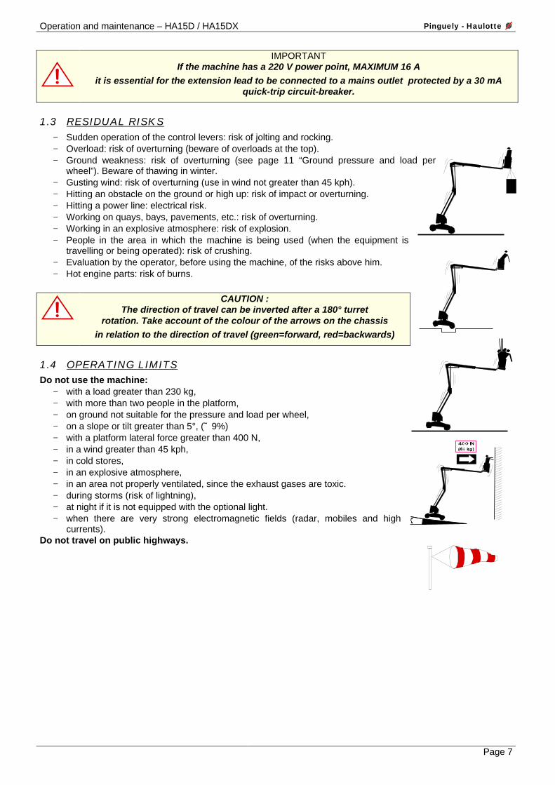
1.3 RESIDUAL RISKS − Sudden operation of the control levers: risk of jolting and rocking. − Overload: risk of overturning (beware of overloads at the top). − Ground weakness: risk of overturning (see page 11 “Ground pressure and load per
wheel”). Beware of thawing in winter. − Gusting wind: risk of overturning (use in wind not greater than 45 kph). − Hitting an obstacle on the ground or high up: risk of impact or overturning. − Hitting a power line: electrical risk. − Working on quays, bays, pavements, etc.: risk of overturning. − Working in an explosive atmosphere: risk of explosion. − People in the area in which the machine is being used (when the equipment is
travelling or being operated): risk of crushing. − Evaluation by the operator, before using the machine, of the risks above him. − Hot engine parts: risk of burns.
CAUTION : The direction of travel can be inverted after a 180° turret
rotation. Take account of the colour of the arrows on the chassis in relation to the direction of travel (green=forward, red=backwards)
1.4 OPERATING LIMITS Do not use the machine:
− with a load greater than 230 kg, − with more than two people in the platform, − on ground not suitable for the pressure and load per wheel, − on a slope or tilt greater than 5°, (˜ 9%) − with a platform lateral force greater than 400 N, − in a wind greater than 45 kph, − in cold stores, − in an explosive atmosphere, − in an area not properly ventilated, since the exhaust gases are toxic. − during storms (risk of lightning), − at night if it is not equipped with the optional light. − when there are very strong electromagnetic fields (radar, mobiles and high
currents). Do not travel on public highways.
Pinguely - Haulotte Operation and maintenance – HA15D / HA15DX
Page 8
1.5 VERIFICATIONS Comply with the national regulations in force in the country of use. For FRANCE: Order of June 9th 1993 + circular DRT 93-22 September 1993 specifying:
1.5.1 Routine verifications
The machine must be the subject of routine inspections every 6 months so that any defect liable to cause an accident is detected. These inspections must be carried out by an organisation or personnel specially designated by the head of establishment and under the latter’s responsibility (company’s personnel or not) – Articles R 233-5 and R 233-11 of the Code du Travail. The result of these inspections must be entered in a safety register opened by the head of establishment and kept constantly available to the works inspector and safety committee of the establishment, if there is one, as well as a list of the specially designated personnel (Article R 233-5 of the Code du Travail). NOTE : Such registers can be obtained from the trade organisations and some of them can be obtained from the OPPBTP or private prevention organisations. The people designated must be experienced in the field of risk prevention (Articles R 233-11 of Decree n° 93-41). It is forbidden to allow any worker to proceed, during the operation of the machine, with any verification whatsoever (Article R 233-11 of the Code du Travail).
1.5.2 Examination of suitability of a machine
The head of the establishment in which this equipment is put into service must make sure of the suitability of the machine, that is, that it is appropriate for the works to be carried out safely and that it is used in accordance with the instruction manual. In addition, in the above-mentioned French order of June 9th 1993, problems associated with hiring, the examination of the state of conservation, verification at the time of putting back into service after repair, as well as coefficient 1.25 static test and coefficient 1.1 dynamic test conditions are mentioned. Each person responsible using the machine must acquaint himself and follow the requirements of this decree.
1.5.3 State of conservation
Detect any damage liable to be the cause of dangerous situations (safety devices, load limiters, tilt monitor, leaks from cylinders, deformation, condition of welds, tightness of bolts, hoses, electrical connections, condition of tyres, excessive mechanical play. NOTE : In the case of hiring, the person responsible using the hired machine has the responsibility of examining the state of conservation and for examining suitability. He must check with the hirer that the routine general verifications and verifications before putting into service have indeed been carried out.
1.6 REPAIRS AND ADJUSTMENTS Major repairs, maintenance work or adjustments on the safety elements or systems (concerns mechanics, hydraulics and electricity). These must be carried out by PINGUELY-HAULOTTE personnel or personnel working on behalf of PINGUELY-HAULOTTE who must use original parts only. Any modification outside PINGUELY-HAULOTTE’s control is not authorised. The manufacturer is not liable if original parts are not used or if the work specified above is not carried out by PINGUELY-HAULOTTE approved personnel.
1.7 VERIFICATIONS AT THE TIME OF PUTTING BACK INTO SERVICE To be carried out after:
− major removal/refitting, − a repair involving the machine’s essential parts, − any accident caused by the failure of an essential part.
It is necessary to proceed with an examination of suitability, an examination of the state of conservation, a static test, a dynamic test (see coefficients, chapter 1.5.2).

Operation and maintenance – HA15D / HA15DX Pinguely - Haulotte
Page 9
2. PRESENTATION
The HA 15 D self-propelled access platform is designed for any high work within the limit of its characteristics (see chapters 2.3 and 2.4) and complying with all the safety instructions particular to the machine and to the locations where it is used. The main operating post is in the platform. The turret operating post is an emergency or back-up post.
2.1 IDENTIFICATION A plate, fixed on the back right of the chassis, bears all the indications (engraved) enabling the machine to be identified.
REMINDER: Whenever requesting information, intervention or spares, specify the type and serial n°.

Pinguely - Haulotte Operation and maintenance – HA15D / HA15DX
Page 10
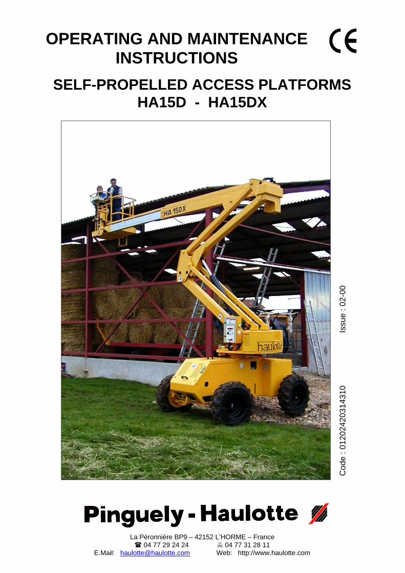
2.2 MAIN COMPONENTS
1 - Drive wheels 2 - Rolling chassis. 3 - Hydraulic travel motors and reducers 4 - Steered wheels 5 - Platform compensation input cylinder 6 - Platform 7 - Platform control panel 8 - Platform support with load limiter 9 - Link piece
10 - Arms lifting cylinder 11 - Bottom arm
12 - Top arm 13 - Boom raising cylinder 14 - Slewing ring 15 - 2-piece boom 16 - Boom support 17 - Heat engine and hydraulic pump 18 - Lifting and fixing lugs 19 - Turret 20 - Ground control panel 21 - Boom telescoping cylinder 22 - Direction/steering
Operation and maintenance – HA15D / HA15DX Pinguely - Haulotte
Page 11
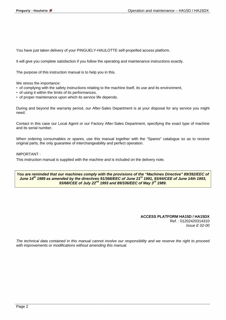
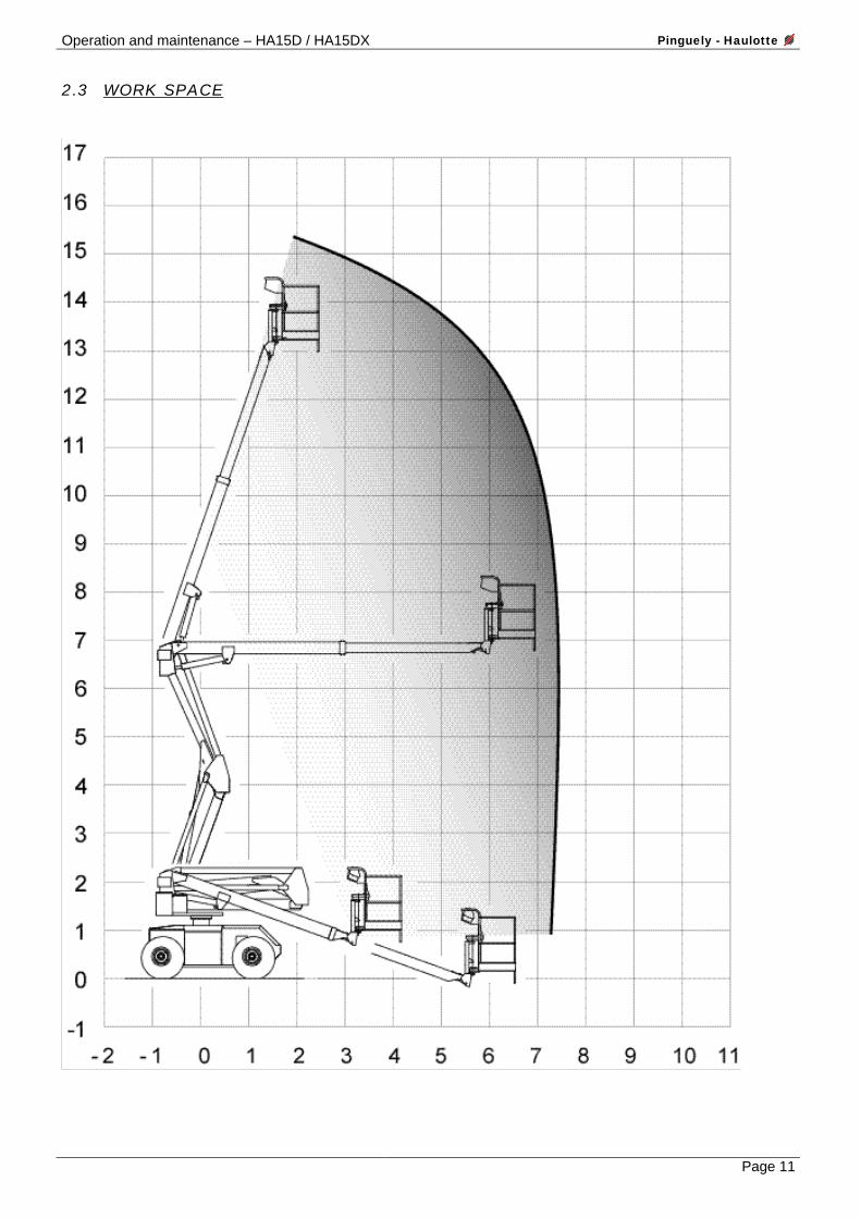
2.3 WORK SPACE

Pinguely - Haulotte Operation and maintenance – HA15D / HA15DX
Page 12
2.4 TECHNICAL CHARACTERISTICS.
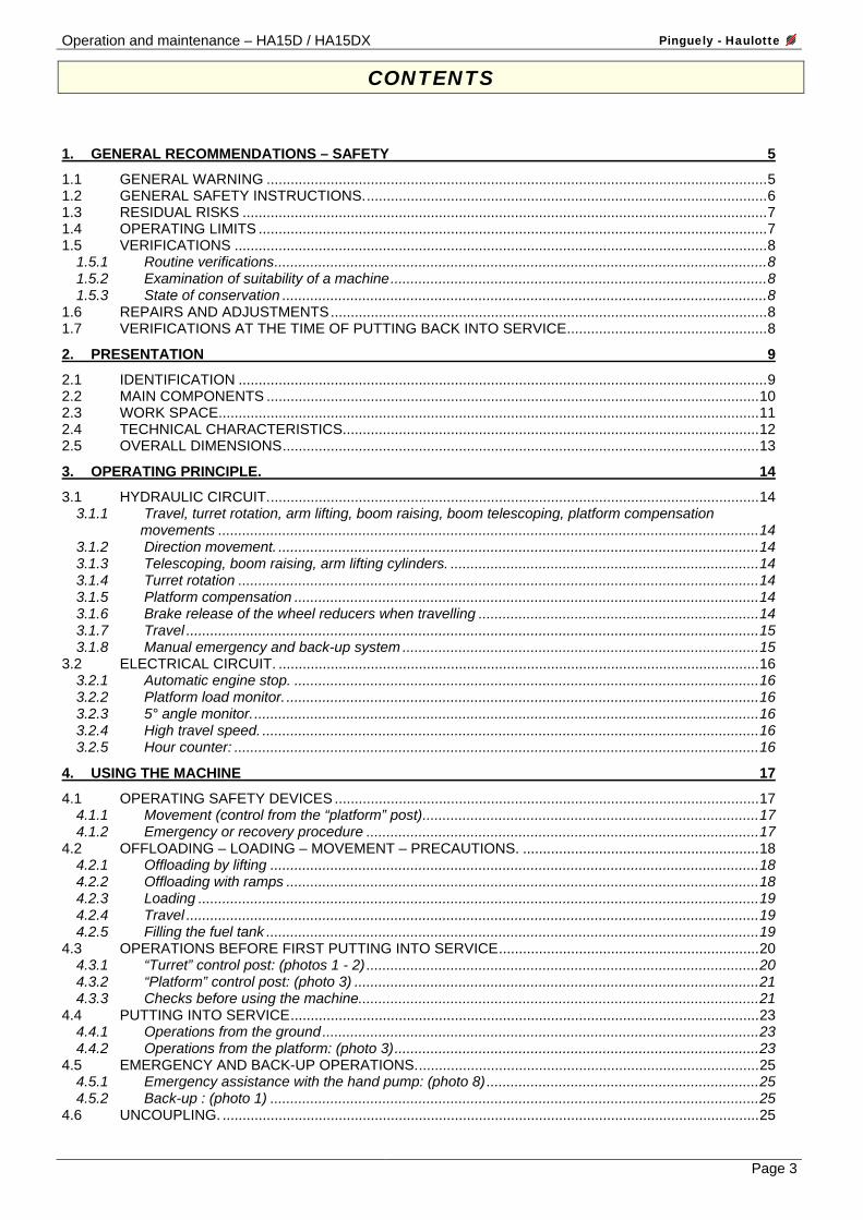
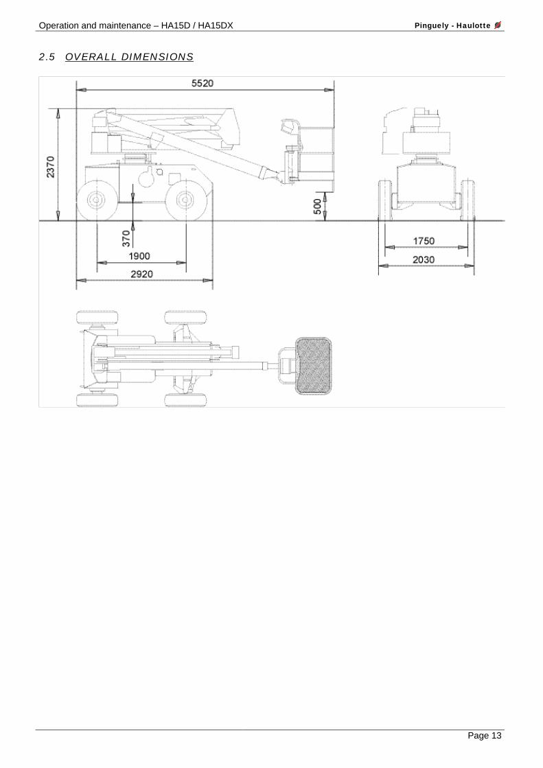
DESIGNATIONS HA15D HA 15DX Charge 230 kg including 2 people Maximum lateral manual force 400 N Max. wind speed 45 kph Floor height 13.20 m Working height 15.20 m Overall length 5.52 m Overall width 2.05 m Overall height 2.40 m Wheelbase 1.90 m Ground clearance 370 mm Max. reach 7.50 m Boom range -20° / +71° Telescoping (stroke) 2550 mm Turret rotation 360° Max. force on wheel 3000 daN Max. ground pressure: - On soft ground - On hard ground
4 kg/cm² 14 kg/cm²
Max. travel slope 25% 40% Tyre sizes 10.5’’ x 18’’ Outside turning radius 4.5 m Tilt – Monitor 5° (˜ 9%) Hydraulic reservoir 150 litres Diesel tank 65 litres Total weight 5450 kg 5600 kg Number of drive wheels 2 4 Number of steered wheels 2 Differential lock YES Hydraulic brakes YES Freewheeling YES Wheel nut tightening torque 320 m.N Vibration level at feet < 0.5 m/s² Vibration level at hands < 2.5 m/s² Operating post sound level 78 dB(A) Hatz Silent-pack 2L41C diesel engine - Power output - Idling
32.6 HP / 24 kW at 2400 rpm.
1250 rpm. 22.8 + 8 cm3/rev hydraulic pump - Travel and movements - Steering
52 l/min. 18 l/min.
Hydraulic pressure - General - Travel - Steering - Slewing - Equipment
210 bar 210 bar 100 bar 75 bar 210 bar
Travel speed (proportional)
LS : 0.8 kph HS : 4.6 kph
LS : 0.8 kph IS : 2.3 kph HS : 4.6 kph
Starting battery 12 V - 95 Ah Supply voltage 12 V
Operation and maintenance – HA15D / HA15DX Pinguely - Haulotte
Page 13
2.5 OVERALL DIMENSIONS
Pinguely - Haulotte Operation and maintenance – HA15D / HA15DX
Page 14
3. OPERATING PRINCIPLE.
3.1 HYDRAULIC CIRCUIT. See hydraulic diagrams: • HA15D B 15361 • HA15DX B 15362 All the machine’s movements are provided by hydraulic power. This is supplied by a gear pump driven by a heat engine. In the event of a breakdown, a manual back-up pump permits lowering of the arms and boom, retraction of the telescope, compensation and slewing of the turret. A high pressure filter mounted on the pump’s delivery protects the installation from pollution.
3.1.1 Travel, turret rotation, arm lifting, boom raising, boom telescoping, platform compensation movements
These are controlled by shuttle valves via a proportional control valve which gives progressiveness of movement. A single movement at a time is possible.
3.1.2 Direction movement.
This is controlled by a solenoid-operated shuttle valve supplied by the small pump body.
3.1.3 Telescoping, boom raising, arm lifting cylinders.
These are equipped with balancing valves, leakproof and flanged on their bodies.
IMPORTANT : Adjustment can only be carried out by specialist personnel.
Disturbing the settings may cause the machine’s safety devices not to work, and consequently risks of serious accidents.
3.1.4 Turret rotation This is provided by a ring and reducer assembly, driven by a hydraulic motor.
3.1.5 Platform compensation
This works by oil transfer between 2 cylinders with similar characteristics. The compensation input cylinder is equipped with a flanged double piloted valve. The manual compensation speed is controlled by a limitation of the operating speed of the electropump specific to this movement.
3.1.6 Brake release of the wheel reducers when travelling
Whenever a travel movement is actuated, the brake release circuit for the reducers mounted on the fixed axle is pressurised. As soon as the movement stops, or if there is a lack of pressure, the brake is applied again.
Operation and maintenance – HA15D / HA15DX Pinguely - Haulotte
Page 15
3.1.7 Travel
3.1.7.1 4 x 2 version.
Two hydraulic motors drive the wheels on the fixed axle via epicyclic reducers. Two speeds (high, low) are controlled by a switch. • High speed – 4 x 2: The 2 motors are supplied in series, they receive the pump’s flow which goes into one
motor and then the other. • Low speed – 4 x 2: The 2 motors are supplied in parallel, each receives half of the pump’s flow.
3.1.7.2 4 x 4 version. Four hydraulic motors drive the wheels via epicyclic reducers. Three speeds (high, intermediate, low) are controlled by a switch. • High speed - 4 x 4 : The fixed axle’s 2 motors are supplied in series, the steered axle is in freewheel. • Intermediate speed - 4 x 4 : The fixed axle’s 2 motors are supplied in parallel, the steered axle is in freewheel. • Low speed - 4 x 4 : Each axle receives half of the flow supplied by the pump. On each axle the motors are
supplied in parallel. One hydraulic differential lock per axle is useable in low and intermediate speed.
3.1.8 Manual emergency and back-up system In the event of a breakdown preventing:
• use of the pump, • operation of the movements,
it is possible to carry out these movements from the ground, by means of a hand pump. At the same time as the use of the back-up pump, it is necessary to operate manually the corresponding solenoid valve in order to carry out the arms down, boom down, telescope retraction and turret slewing and platform compensation movements.

Pinguely - Haulotte Operation and maintenance – HA15D / HA15DX
Page 16
3.2 ELECTRICAL CIRCUIT. The electrical energy used for the controls and for starting the heat engine is supplied by a 12 V battery. Details of the main safety devices:
3.2.1 Automatic engine stop. In the event of: • oil pressure too low • clogging of the air filter • braking of the fan or alternator belt
3.2.2 Platform load monitor.
If the platform load reaches 90% of the maximum permitted load, the buzzer alerts the operator. When this maximum load is reached, the control circuit is cut, preventing all movements. It is necessary to shed some load in order to reset the unit.
3.2.3 5° angle monitor.
The tilt monitor box gives an audible signal when the maximum permissible angle is reached. If this situation persists, after a time delay of 1 to 2 seconds, the controls of the boom raising (up), arm raising (up) and telescoping (extension) movements are cut, as well as travel so long as the machine is deployed. In order to use travel again, it is necessary to fold all of the elevation elements. NOTE: With the machine folded, the tilt monitor box gives an audible signal so long as the slope is greater than 5°, indicating to the operator that it will be impossible to deploy the platform.
3.2.4 High travel speed.
The high and intermediate travel speeds (4 x 4 model) are permitted only when the platform is completely folded. When the boom is raised or telescoped or the arms deployed, only low speed is possible.
3.2.5 Hour counter:
An hour counter indicates how long the heat engine has been operating.
Operation and maintenance – HA15D / HA15DX Pinguely - Haulotte
Page 17
4. USING THE MACHINE
4.1 OPERATING SAFETY DEVICES For the purpose of not enabling the machine to be used beyond its possibilities, safety devices are provided to protect the personnel and the machine.
They immobilise the machine or neutralise the movements. In this case poor knowledge of the characteristics and operation of the machine can lead one to believe that there is a breakdown when in fact it is the safety devices which are working properly. It is therefore essential to assimilate all the instructions in the following chapters.
IMPORTANT Do not carry out any operations before having assimilated the instructions in chapter 4.4.
4.1.1 Movement (control from the “platform” post)
To move the machine, it is necessary to enable the “dead man’s” safety device by keeping the movement control manipulator’s ring raised (see chapter 4.3.2). Travel is possible up to a maximum slope of 5° (about 9%). In order to permit movement of the machine for access to the work place, unloading or loading with slopes greater than 5° and 40% maximum, it is necessary to ensure that: • the arms and boom are lowered, • the telescope is completely retracted.
Otherwise the machine is immobilised. REMINDER: The high and intermediate travel speeds (4x4 model) are only permitted if the arms are folded, the boom is down and the telescope is retracted.
4.1.2 Emergency or recovery procedure
CAUTION In the event of the need to proceed with an emergency or recovery operation, the safety devices
being neutralised, only a competent operator can carry out these operations.
Pinguely - Haulotte Operation and maintenance – HA15D / HA15DX
Page 18
4.2 OFFLOADING – LOADING – MOVEMENT – PRECAUTIONS. IMPORTANT : Before any operation, check the condition of the machine, so as to make sure that it has not been damaged during transport. Otherwise, make the necessary reserves with the carrier in writing.
IMPORTANT An incorrect operation can cause the machine to fall and cause very serious bodily injury and
material damage.
Carry out the offloading operations on a stable, sufficiently resistant (see chapter 2.4 – Ground pressure), flat and uncluttered surface.
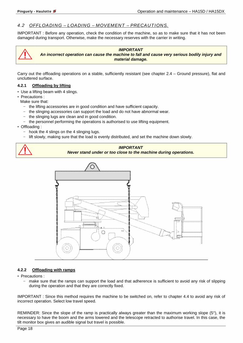
4.2.1 Offloading by lifting
• Use a lifting beam with 4 slings. • Precautions :
Make sure that: − the lifting accessories are in good condition and have sufficient capacity. − the slinging accessories can support the load and do not have abnormal wear. − the slinging lugs are clean and in good condition. − the personnel performing the operations is authorised to use lifting equipment.
• Offloading : − hook the 4 slings on the 4 slinging lugs. − lift slowly, making sure that the load is evenly distributed, and set the machine down slowly.
IMPORTANT Never stand under or too close to the machine during operations.
4.2.2 Offloading with ramps
• Precautions : − make sure that the ramps can support the load and that adherence is sufficient to avoid any risk of slipping
during the operation and that they are correctly fixed. IMPORTANT : Since this method requires the machine to be switched on, refer to chapter 4.4 to avoid any risk of incorrect operation. Select low travel speed. REMINDER: Since the slope of the ramp is practically always greater than the maximum working slope (5°), it is necessary to have the boom and the arms lowered and the telescope retracted to authorise travel. In this case, the tilt monitor box gives an audible signal but travel is possible.
Operation and maintenance – HA15D / HA15DX Pinguely - Haulotte
Page 19
If the slope is greater than the maximum travel slope (40%): use a hoist in addition to traction.
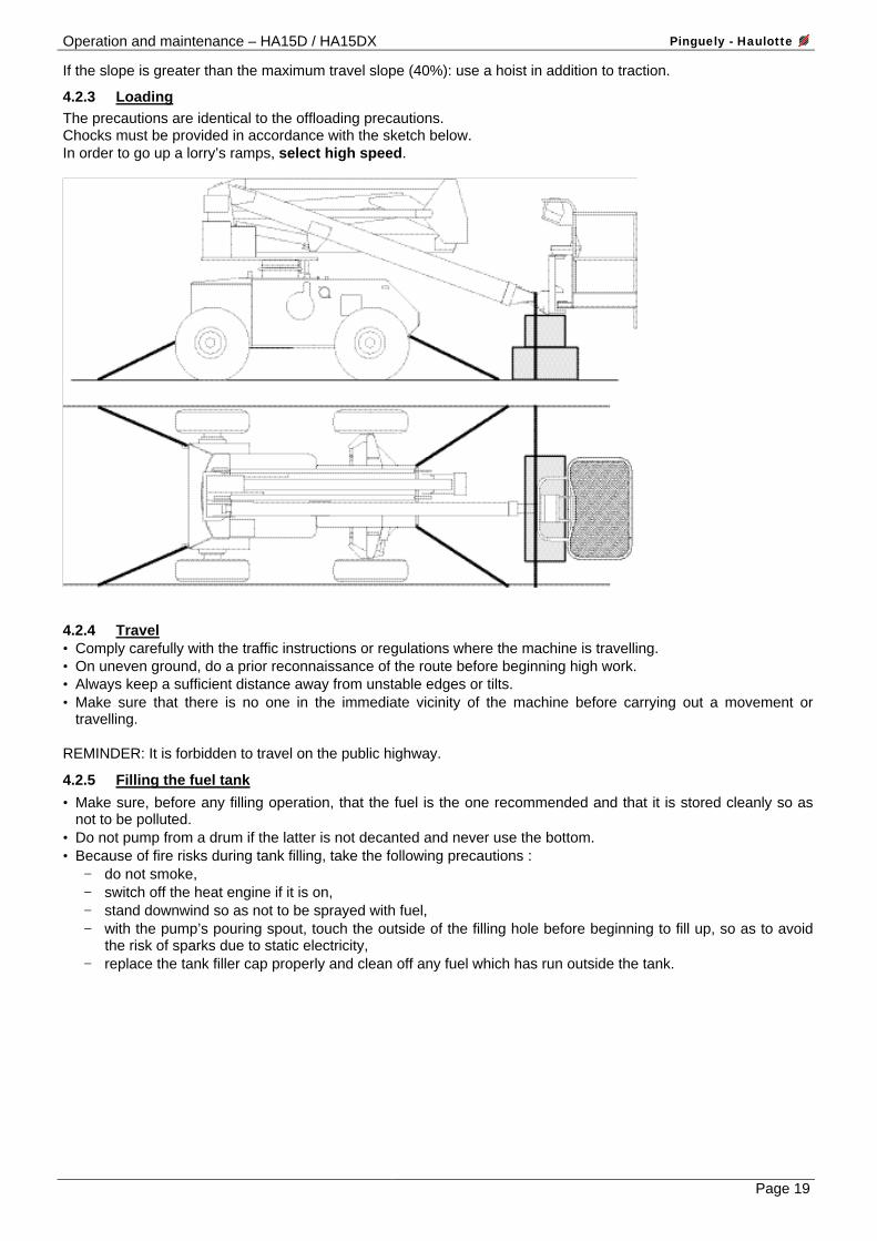
4.2.3 Loading The precautions are identical to the offloading precautions. Chocks must be provided in accordance with the sketch below. In order to go up a lorry’s ramps, select high speed.
4.2.4 Travel • Comply carefully with the traffic instructions or regulations where the machine is travelling. • On uneven ground, do a prior reconnaissance of the route before beginning high work. • Always keep a sufficient distance away from unstable edges or tilts. • Make sure that there is no one in the immediate vicinity of the machine before carrying out a movement or
travelling. REMINDER: It is forbidden to travel on the public highway.
4.2.5 Filling the fuel tank
• Make sure, before any filling operation, that the fuel is the one recommended and that it is stored cleanly so as not to be polluted.
• Do not pump from a drum if the latter is not decanted and never use the bottom. • Because of fire risks during tank filling, take the following precautions :
− do not smoke, − switch off the heat engine if it is on, − stand downwind so as not to be sprayed with fuel, − with the pump’s pouring spout, touch the outside of the filling hole before beginning to fill up, so as to avoid
the risk of sparks due to static electricity, − replace the tank filler cap properly and clean off any fuel which has run outside the tank.
Pinguely - Haulotte Operation and maintenance – HA15D / HA15DX
Page 20
4.3 OPERATIONS BEFORE FIRST PUTTING INTO SERVICE REMINDER: Before any operation, familiarise yourself with the machine by referring to this manual, the engine’s manual, and the instructions on the various plates.
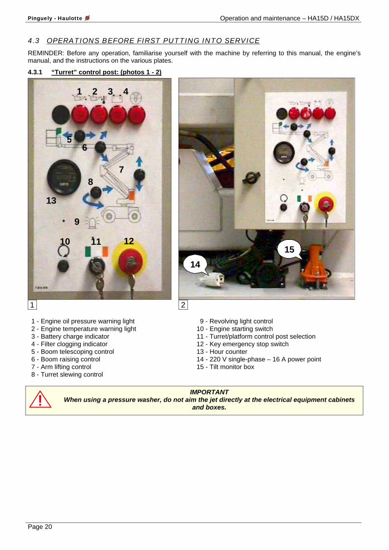
4.3.1 “Turret” control post: (photos 1 - 2)
1 2 3 4
11 12
8
10
7
6 5
9
13
1
14
15
2
1 - Engine oil pressure warning light 2 - Engine temperature warning light 3 - Battery charge indicator 4 - Filter clogging indicator 5 - Boom telescoping control 6 - Boom raising control 7 - Arm lifting control 8 - Turret slewing control
9 - Revolving light control 10 - Engine starting switch 11 - Turret/platform control post selection 12 - Key emergency stop switch 13 - Hour counter 14 - 220 V single-phase – 16 A power point 15 - Tilt monitor box
IMPORTANT When using a pressure washer, do not aim the jet directly at the electrical equipment cabinets
and boxes.
Operation and maintenance – HA15D / HA15DX Pinguely - Haulotte
Page 21
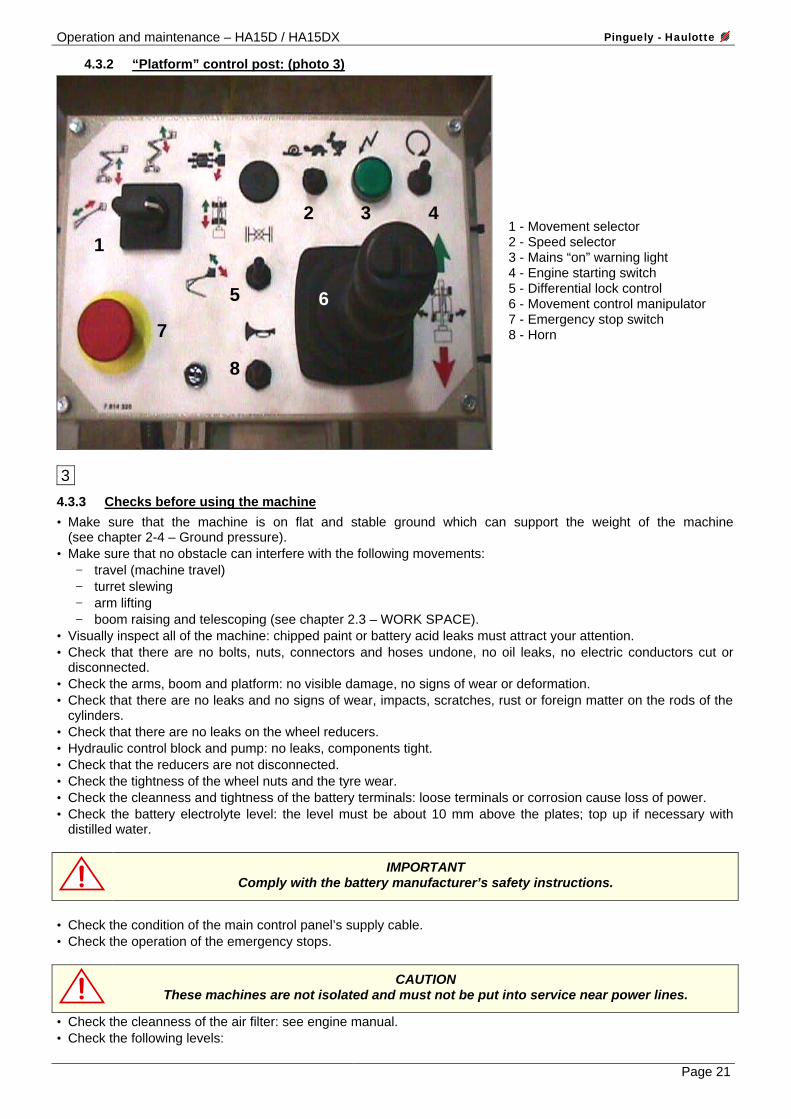
4.3.2 “Platform” control post: (photo 3)
1
2 3 4
5
8
7
6
3
1 - Movement selector 2 - Speed selector 3 - Mains “on” warning light 4 - Engine starting switch 5 - Differential lock control 6 - Movement control manipulator 7 - Emergency stop switch 8 - Horn
4.3.3 Checks before using the machine
• Make sure that the machine is on flat and stable ground which can support the weight of the machine (see chapter 2-4 – Ground pressure).
• Make sure that no obstacle can interfere with the following movements: − travel (machine travel) − turret slewing − arm lifting − boom raising and telescoping (see chapter 2.3 – WORK SPACE).
• Visually inspect all of the machine: chipped paint or battery acid leaks must attract your attention. • Check that there are no bolts, nuts, connectors and hoses undone, no oil leaks, no electric conductors cut or
disconnected. • Check the arms, boom and platform: no visible damage, no signs of wear or deformation. • Check that there are no leaks and no signs of wear, impacts, scratches, rust or foreign matter on the rods of the
cylinders. • Check that there are no leaks on the wheel reducers. • Hydraulic control block and pump: no leaks, components tight. • Check that the reducers are not disconnected. • Check the tightness of the wheel nuts and the tyre wear. • Check the cleanness and tightness of the battery terminals: loose terminals or corrosion cause loss of power. • Check the battery electrolyte level: the level must be about 10 mm above the plates; top up if necessary with
distilled water.
IMPORTANT Comply with the battery manufacturer’s safety instructions.
• Check the condition of the main control panel’s supply cable. • Check the operation of the emergency stops.
CAUTION These machines are not isolated and must not be put into service near power lines.
• Check the cleanness of the air filter: see engine manual. • Check the following levels:
Pinguely - Haulotte Operation and maintenance – HA15D / HA15DX
Page 22
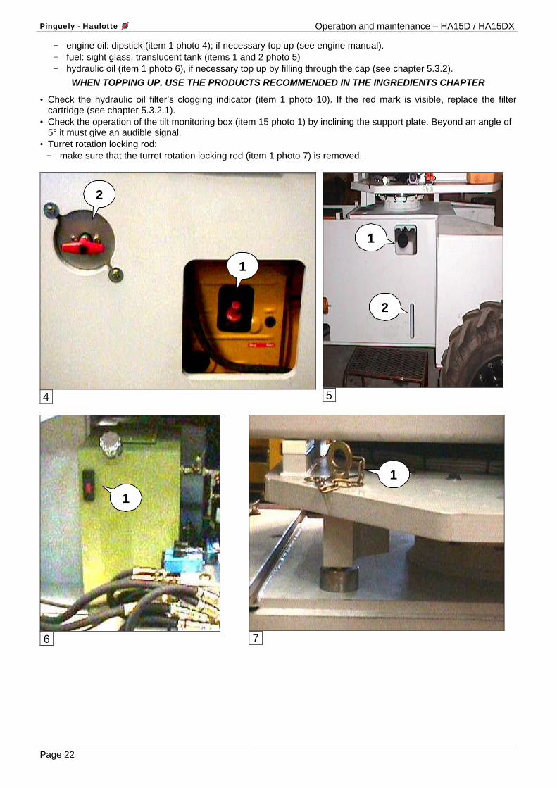
− engine oil: dipstick (item 1 photo 4); if necessary top up (see engine manual). − fuel: sight glass, translucent tank (items 1 and 2 photo 5) − hydraulic oil (item 1 photo 6), if necessary top up by filling through the cap (see chapter 5.3.2).
WHEN TOPPING UP, USE THE PRODUCTS RECOMMENDED IN THE INGREDIENTS CHAPTER
• Check the hydraulic oil filter’s clogging indicator (item 1 photo 10). If the red mark is visible, replace the filter cartridge (see chapter 5.3.2.1).
• Check the operation of the tilt monitoring box (item 15 photo 1) by inclining the support plate. Beyond an angle of 5° it must give an audible signal.
• Turret rotation locking rod: − make sure that the turret rotation locking rod (item 1 photo 7) is removed.
1
2
4
1
2
5
1
6
1
7

Operation and maintenance – HA15D / HA15DX Pinguely - Haulotte
Page 23
4.4 PUTTING INTO SERVICE IMPORTANT : Putting into service must begin only when all the operations in the previous chapter have been
scrupulously carried out. To familiarise yourself with the machine, it is necessary to do the first operations on the ground, leaving the machine in the transport position: counterweight forward, boom and arms lowered.
CAUTION : When the counterweight is placed above the steered wheels, the travel and direction controls
react in the opposite direction.
REMINDER: The main operating post is in the platform. In normal use the “turret” operating post is an emergency or back-up post and must be used only if absolutely necessary.
4.4.1 Operations from the ground
• Close the battery breaker (item 2 photo 4).
4.4.1.1 Starting the engine: (photo 1)
• Make sure that the emergency stop button (item 12) is pulled out. • Put the control post selection key switch (item 11) in the “ground control” position (right pictogram). In this position
the “platform” panel’s controls are overridden. • The battery charge (item 3) and engine oil pressure (item 1) warning lights are “on”. The air filter clogging light
(item 4) is “off”. • Press the starting button (item 10); when the engine has started, the “on” lights (items 1 and 3) go off.
NOTE : If the engine does not start, switch off the ignition by pressing the emergency stop button and start the operation again. • Check the operation of the pump and engine hour counter (item 13).
4.4.1.2 Testing the movements: (photo 1) REMINDER: Make sure before any movement that no obstacle can interfere with the operations. • The actuation of movements automatically causes the engine to speed up. • Test the arms lifting movement in the “up” and then “down” direction (switch, item 7). • Test the boom raising movement in the “up” and then “down” direction (switch, item 6). Stop the boom “down”
movement when it is in the horizontal position. • Then test the turret slewing movements in both directions (switch, item 8) and the boom’s extension and then
retraction telescoping (switch, item 5), then lower the boom again completely.
4.4.1.3 Switching to “platform” control
• Put the control post’s key selector switch (item 11 photo 1) in the “platform” position (left pictogram). • Check the operation of the tilt monitoring box (item 15 photo 2). To facilitate access to the platform basket, it is recommended that the lowered boom be telescoped.
4.4.2 Operations from the platform: (photo 3)
• Get into the basket, complying with the maximum load instructions, and if necessary distributing the load over the whole platform.
MAXIMUM LOAD: 230 kg including 2 people.
NOTE : If you are approaching the maximum load, the buzzer must give an audible signal. If this load is exceeded, all the machine’s movements are cut off. It is then necessary to shed the load. There is no load restriction with the reach.
Pinguely - Haulotte Operation and maintenance – HA15D / HA15DX
Page 24
4.4.2.1 Testing the control post
• Make sure before any operation that the green light (item 3) is “on”. This indicates that the machine is “on” and that the control post’s selector switch is in the “platform” position.
• Make sure that the emergency stop button (item 7) is unlocked. • Check the operation of the horn.
4.4.2.2 Testing the movements To carry out a movement, it is necessary first of all to select it (item 1) and then to activate the “dead man’s” safety device by keeping the movement control manipulator’s ring (item 6) raised and then to operate this manipulator in the required direction. The direction of movements obtained with the manipulator is indicated by a red arrow and a green arrow. The speed and angle of the manipulator will give progressiveness of the movement. • If the floor is not horizontal, correct the position of the platform by putting the selector switch in the “manual
compensation” position. Lift the ring and operate the manipulator forwards or backwards. • Test the telescoping, arms lifting, boom raising and slewing movements by putting the selector switch in turn in
the corresponding positions. In each selector switch position, raise the ring and operate the manipulator forwards or backwards.
• Put the selector switch in the position corresponding to travel. Lift the ring and operate the manipulator from right to left in order to obtain the direction movement. This function reacts “all or nothing” without progressiveness.
• Test travel by keeping the ring lifted and by operating this time the manipulator forwards or backwards.
CAUTION : The direction of travel can be the other way round after a 180° turret rotation.
Take account of the colour of the arrows on the chassis in relation to the direction of travel (green=forwards, red=backwards).
• Test the travel speeds by operating the selector switch (item 2) CAUTION : The high and intermediate travel speeds (4 x 4 model) are possible only if the machine is totally folded. Even slightly deployed, only the low speed is permitted. The work can begin.
Operation and maintenance – HA15D / HA15DX Pinguely - Haulotte
Page 25
4.5 EMERGENCY AND BACK-UP OPERATIONS.
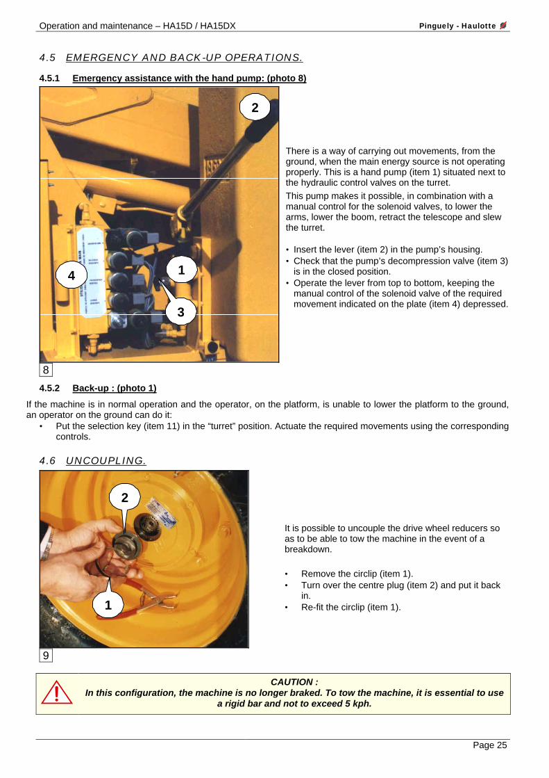
4.5.1 Emergency assistance with the hand pump: (photo 8)
1
2
3
4
8
There is a way of carrying out movements, from the ground, when the main energy source is not operating properly. This is a hand pump (item 1) situated next to the hydraulic control valves on the turret. This pump makes it possible, in combination with a manual control for the solenoid valves, to lower the arms, lower the boom, retract the telescope and slew the turret. • Insert the lever (item 2) in the pump’s housing. • Check that the pump’s decompression valve (item 3)
is in the closed position. • Operate the lever from top to bottom, keeping the
manual control of the solenoid valve of the required movement indicated on the plate (item 4) depressed.
4.5.2 Back-up : (photo 1)
If the machine is in normal operation and the operator, on the platform, is unable to lower the platform to the ground, an operator on the ground can do it:
• Put the selection key (item 11) in the “turret” position. Actuate the required movements using the corresponding controls.
4.6 UNCOUPLING.
1
2
9
It is possible to uncouple the drive wheel reducers so as to be able to tow the machine in the event of a breakdown. • Remove the circlip (item 1). • Turn over the centre plug (item 2) and put it back
in. • Re-fit the circlip (item 1).
CAUTION : In this configuration, the machine is no longer braked. To tow the machine, it is essential to use
a rigid bar and not to exceed 5 kph.

Pinguely - Haulotte Operation and maintenance – HA15D / HA15DX
Page 26
5. MAINTENANCE.
5.1 GENERAL RECOMMENDATIONS. The maintenance operations indicated in this manual are given for normal conditions of use. In difficult conditions: extreme temperatures, high humidity, polluting atmosphere, high altitude, etc., some operations must be carried out more frequently and special precautions must be taken. Refer to the engine manual and your local PINGUELY-HAULOTTE agent. Only qualified and competent personnel can carry out any work on the machine and they must comply with the safety instructions relating to the protection of personnel and environmental protection.
For the engine part, refer to the instructions in the engine manufacturer’s manual.
At regular intervals, check the operation of the safety devices: • Tilt monitor (tilt > 5°): buzzer + stopping of the following movements: travel, arm lifting, boom raising and
telescope extension. • Platform overload (load > 230 kg): buzzer + complete stopping of all movements • Travelling at high and intermediate speeds (4x4 model) impossible if arms lifted, boom raised or telescope
extended. CAUTION : • do not use the machine as a welding earth. • do not weld without disconnecting the battery’s (+) and (-) terminals. • do not start other vehicles with the battery connected.
5.2 MAINTENANCE SCHEDULE. The schedule on the next page indicates the intervals, the maintenance points (parts) and the ingredients to be used. • The mark in the symbol indicates the maintenance point depending on the interval. • The symbol represents the ingredient to be used (or the operation to be carried out).
INGREDIENT SPECIFICATION SYMBOLE
Lubricants used by
PINGUELY HAULOTTE
ELF TOTAL
Engine oil SAE 20 W
ESSO HD X 30
PERFORMANCE XC 30
RUBIA S 30
Gearbox oil SAE 90
ESSO EP 80 W 90
TRANSELF EP 80 W 90
TM 80 W/90
Hydraulic oil AFNOR 48602
ISO VG 46
BP SHF ZS 46
HYDRELF DS 46
EQUIVIS ZS 46
Lithium extreme pressure grease ISO - XM – 2
Lead-free grease Grade 2 or 3
ESSO
GP GREASE MULTIMOTIVE 2 MULTIS EP 2
Replacement or special
operation
Lithium grease ENS / EP 700
Mobilux EP2

Operation and maintenance – HA15D / HA15DX Pinguely - Haulotte
Page 27
MAINTENANCE SCHEDULE
Pinguely - Haulotte Operation and maintenance – HA15D / HA15DX
Page 28
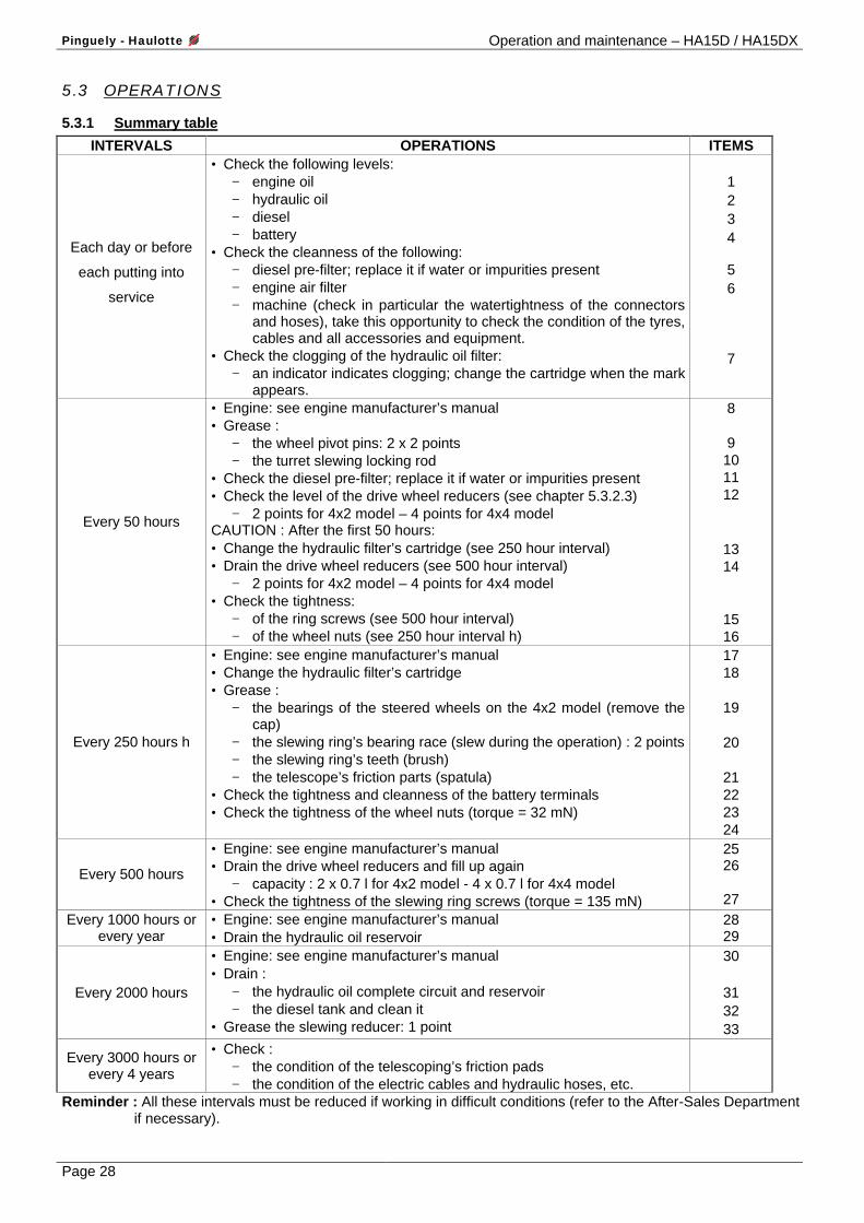
5.3 OPERATIONS
5.3.1 Summary table
INTERVALS OPERATIONS ITEMS
Each day or before
each putting into
service
• Check the following levels: − engine oil − hydraulic oil − diesel − battery
• Check the cleanness of the following: − diesel pre-filter; replace it if water or impurities present − engine air filter − machine (check in particular the watertightness of the connectors
and hoses), take this opportunity to check the condition of the tyres, cables and all accessories and equipment.
• Check the clogging of the hydraulic oil filter: − an indicator indicates clogging; change the cartridge when the mark
appears.
1 2 3 4
5 6
7
Every 50 hours
• Engine: see engine manufacturer’s manual • Grease :
− the wheel pivot pins: 2 x 2 points − the turret slewing locking rod
• Check the diesel pre-filter; replace it if water or impurities present • Check the level of the drive wheel reducers (see chapter 5.3.2.3)
− 2 points for 4x2 model – 4 points for 4x4 model CAUTION : After the first 50 hours: • Change the hydraulic filter’s cartridge (see 250 hour interval) • Drain the drive wheel reducers (see 500 hour interval)
− 2 points for 4x2 model – 4 points for 4x4 model • Check the tightness:
− of the ring screws (see 500 hour interval) − of the wheel nuts (see 250 hour interval h)
8 9 10 11 12
13 14
15 16
Every 250 hours h
• Engine: see engine manufacturer’s manual • Change the hydraulic filter’s cartridge • Grease :
− the bearings of the steered wheels on the 4x2 model (remove the cap)
− the slewing ring’s bearing race (slew during the operation) : 2 points − the slewing ring’s teeth (brush) − the telescope’s friction parts (spatula)
• Check the tightness and cleanness of the battery terminals • Check the tightness of the wheel nuts (torque = 32 mN)
17 18
19
20
21 22 23 24
Every 500 hours
• Engine: see engine manufacturer’s manual • Drain the drive wheel reducers and fill up again
− capacity : 2 x 0.7 l for 4x2 model - 4 x 0.7 l for 4x4 model • Check the tightness of the slewing ring screws (torque = 135 mN)
25 26
27 Every 1000 hours or
every year • Engine: see engine manufacturer’s manual • Drain the hydraulic oil reservoir
28 29
Every 2000 hours
• Engine: see engine manufacturer’s manual • Drain :
− the hydraulic oil complete circuit and reservoir − the diesel tank and clean it
• Grease the slewing reducer: 1 point
30
31 32 33
Every 3000 hours or every 4 years
• Check : − the condition of the telescoping’s friction pads − the condition of the electric cables and hydraulic hoses, etc.
Reminder : All these intervals must be reduced if working in difficult conditions (refer to the After-Sales Department if necessary).
Operation and maintenance – HA15D / HA15DX Pinguely - Haulotte
Page 29
5.3.2 Procedure IMPORTANT : • For filling and greasing operations, use only the lubricants recommended in the table if chapter 5.2 • Collect the drained oils so as not to pollute the environment.
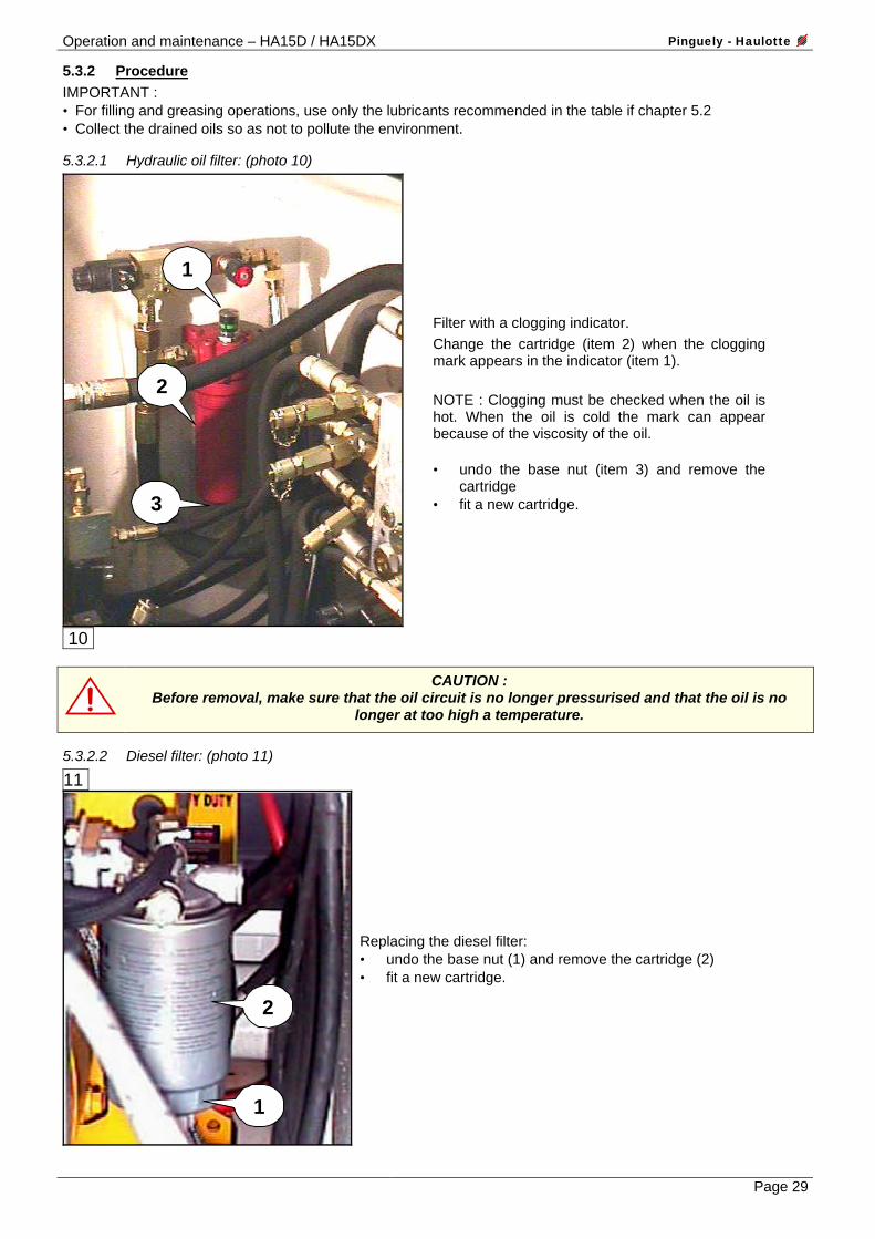
5.3.2.1 Hydraulic oil filter: (photo 10)
1
2
3
10
Filter with a clogging indicator. Change the cartridge (item 2) when the clogging mark appears in the indicator (item 1).
NOTE : Clogging must be checked when the oil is hot. When the oil is cold the mark can appear because of the viscosity of the oil. • undo the base nut (item 3) and remove the
cartridge • fit a new cartridge.
CAUTION : Before removal, make sure that the oil circuit is no longer pressurised and that the oil is no
longer at too high a temperature.
5.3.2.2 Diesel filter: (photo 11)
11
1
2
Replacing the diesel filter: • undo the base nut (1) and remove the cartridge (2) • fit a new cartridge.
Pinguely - Haulotte Operation and maintenance – HA15D / HA15DX
Page 30
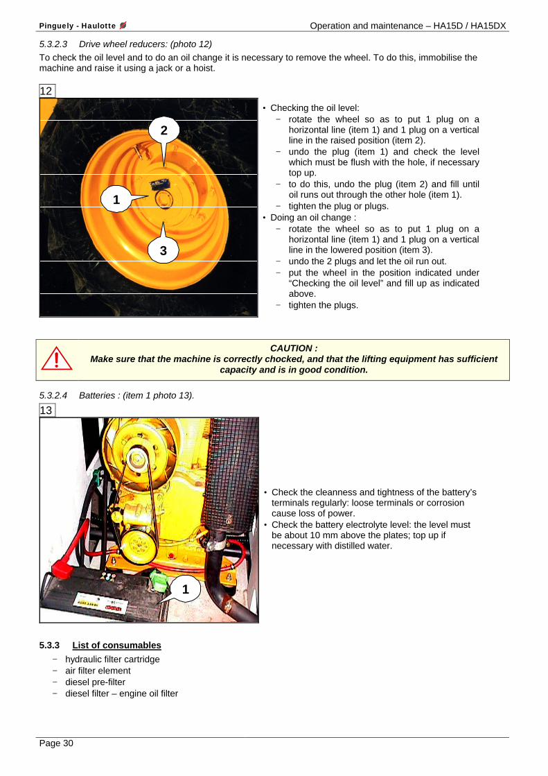
5.3.2.3 Drive wheel reducers: (photo 12) To check the oil level and to do an oil change it is necessary to remove the wheel. To do this, immobilise the machine and raise it using a jack or a hoist. 12
2
3
1
• Checking the oil level: − rotate the wheel so as to put 1 plug on a
horizontal line (item 1) and 1 plug on a vertical line in the raised position (item 2).
− undo the plug (item 1) and check the level which must be flush with the hole, if necessary top up.
− to do this, undo the plug (item 2) and fill until oil runs out through the other hole (item 1).
− tighten the plug or plugs. • Doing an oil change :
− rotate the wheel so as to put 1 plug on a horizontal line (item 1) and 1 plug on a vertical line in the lowered position (item 3).
− undo the 2 plugs and let the oil run out. − put the wheel in the position indicated under
“Checking the oil level” and fill up as indicated above.
− tighten the plugs.
CAUTION : Make sure that the machine is correctly chocked, and that the lifting equipment has sufficient
capacity and is in good condition.
5.3.2.4 Batteries : (item 1 photo 13).
13
1
• Check the cleanness and tightness of the battery’s terminals regularly: loose terminals or corrosion cause loss of power.
• Check the battery electrolyte level: the level must be about 10 mm above the plates; top up if necessary with distilled water.
5.3.3 List of consumables
− hydraulic filter cartridge − air filter element − diesel pre-filter − diesel filter – engine oil filter
Operation and maintenance – HA15D / HA15DX Pinguely - Haulotte
Page 31
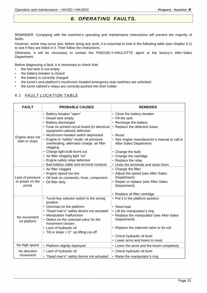
6. OPERATING FAULTS.
REMINDER: Complying with the machine’s operating and maintenance instructions will prevent the majority of faults. However, some may occur and, before doing any work, it is essential to look in the following table (see chapter 6.1) to see if they are listed in it. Then follow the instructions. Otherwise, it will be necessary to contact the PINGUELY-HAULOTTE agent or the factory’s After-Sales Department. Before diagnosing a fault, it is necessary to check that: • the fuel tank is not empty • the battery breaker is closed • the battery is correctly charged • the turret’s and platform’s mushroom-headed emergency stop switches are unlocked • the turret cabinet’s relays are correctly pushed into their holder.
6.1 FAULT LOCATION TABLE
FAULT PROBABLE CAUSES REMEDIES
Engine does not start or stops
• Battery breaker “open” • Diesel tank empty • Battery discharged • Fuse on printed circuit board (in electrical
equipment cabinet) defective • Mushroom-headed switch depressed • Engine in “safety” mode: oil pressure,
overheating, alternator charge, air filter clogging
• Charge light bulb burnt out • Air filter clogging light “on” • Engine safety relay defective • Bad battery cable and terminal contacts
• Close the battery breaker • Fill the tank • Recharge the battery • Replace the defective fuses • Reset • See engine manufacturer’s manual or call in
After-Sales Department • Change the bulb • Change the cartridge • Replace the relay • Undo the terminals and clean them
Lack of pressure or power on the
pump
• Air filter clogged • Engine speed too low • Oil leak on connector, hose, component • Oil filter dirty
• Change the filter • Adjust the speed (see After-Sales
Department) • Repair or replace (see After-Sales
Department) • Replace oil filter cartridge
No movement on platform
• Turret key selector switch in the wrong position
• Overload on the platform • “Dead man’s” safety device not actuated • Manipulator malfunction • Defect on the solenoid valve for the
movement chosen • Lack of hydraulic oil • Tilt or slope > 5°: up lifting cut-off
• Put it in the platform position • Shed load • Lift the manipulator’s ring • Replace the manipulator (see After-Sales
Department) • Replace the solenoid valve or its coil • Check hydraulic oil level • Lower arms and boom to reset
No high speed • Platform slightly deployed • Lower the arms and the boom completely
No direction movement
• Lack of hydraulic oil
• “Dead man’s” safety device not actuated
• Check hydraulic oil level
• Raise the manipulator’s ring
Pinguely - Haulotte Operation and maintenance – HA15D / HA15DX
Page 32
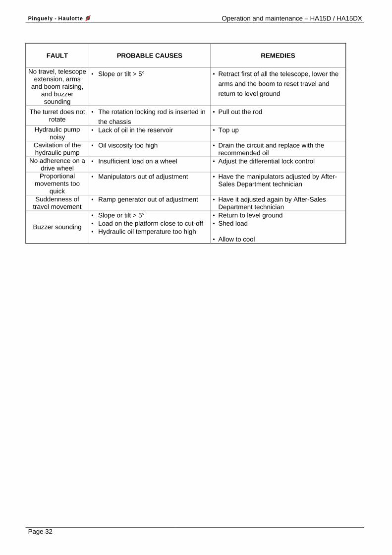
FAULT
PROBABLE CAUSES
REMEDIES
No travel, telescope
extension, arms and boom raising,
and buzzer sounding
• Slope or tilt > 5° • Retract first of all the telescope, lower the arms and the boom to reset travel and return to level ground
The turret does not rotate
• The rotation locking rod is inserted in the chassis
• Pull out the rod
Hydraulic pump noisy
• Lack of oil in the reservoir • Top up
Cavitation of the hydraulic pump
• Oil viscosity too high • Drain the circuit and replace with the recommended oil
No adherence on a drive wheel
• Insufficient load on a wheel • Adjust the differential lock control
Proportional movements too
quick
• Manipulators out of adjustment
• Have the manipulators adjusted by After-Sales Department technician
Suddenness of travel movement
• Ramp generator out of adjustment • Have it adjusted again by After-Sales Department technician
Buzzer sounding
• Slope or tilt > 5° • Load on the platform close to cut-off • Hydraulic oil temperature too high
• Return to level ground • Shed load • Allow to cool

Operation and maintenance – HA15D / HA15DX Pinguely - Haulotte
Page 33
7. SAFETY SYSTEM
7.1 FUNCTIONS OF THE TURRET CABINET FUSES AND RELAYS (see electrical diagram)
LIST FUNCTION
KA 1
KA 2
KA 3
KA 4
KA 5
KA 6
KA 7
KA 8
KA 9
KA 11
KA 12
KA 13
KA 15
KA 17
KA 18
KA 19
KA 20
KA 21
KA 38
KA 39
KL 1
KL 2
FU1 - 3A
FU2 - 80A
FU3 - 3A
FU4 - 3OA
FU5 - 3OA
FU6 - 1OA
FU7 - 2OA
FU8 - 1OA
Prohibits the actuation of boom “up” if the machine’s tilt is greater than 5 %
Prohibits the actuation of arms “up” if the machine’s tilt is greater than 5 %
Prohibits the actuation of telescope extension if the machine’s tilt is greater than 5 %
Prohibits the starting of the heat engine when it is running
Prohibits the actuation of all the movements if the machine’s tilt is greater than 5 %
Permits the starting of the heat engine
Permits the manual actuation of the horn HA 1
Triggers the horn HA 1 according to the temperature
Prohibits the actuation of travel if the machine’s tilt is greater than 5 %
Permits the actuation of forward travel
Permits the cutting of tilt
Permits the actuation of reverse travel
Prohibits change of speed when travelling
Permits the acceleration of the movements
Permits the actuation of intermediate and high speeds
Permits the actuation of high speed
(Option)
(Option)
Permits the actuation of the right/left direction solenoid valve
Permits the actuation of the right/left direction solenoid valve
Permits the actuation of low and intermediate speeds
Permits the actuation of high speed
Signalling circuit protection fuse
Pre-heating circuit protection fuse
Weighing and tilt circuit protection fuse
Movements actuation circuit protection fuse
Accelerator and travel circuit protection fuse
Horn circuit protection fuse
light and rotating light circuit protection fuse
travel pump selection circuit protection fuse
Pinguely - Haulotte Operation and maintenance – HA15D / HA15DX
Page 34
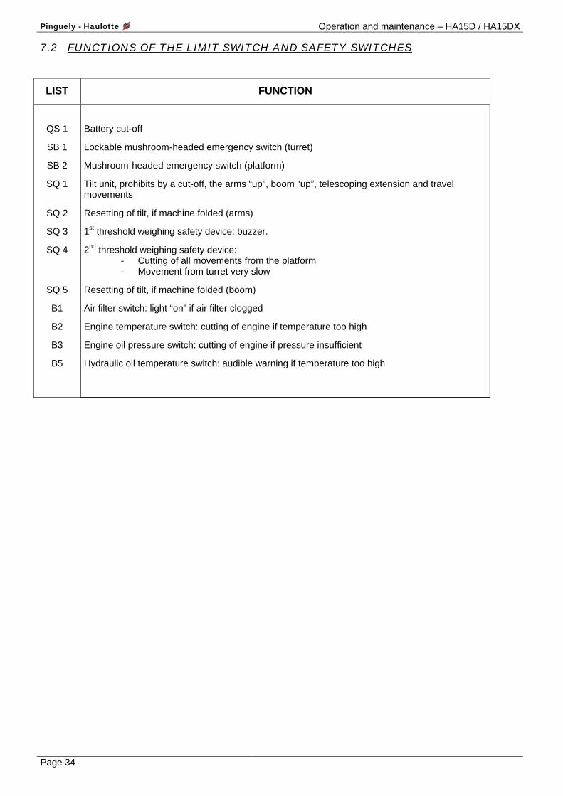
7.2 FUNCTIONS OF THE LIMIT SWITCH AND SAFETY SWITCHES
LIST FUNCTION
QS 1
SB 1
SB 2
SQ 1
SQ 2
SQ 3
SQ 4
SQ 5
B1
B2
B3
B5
Battery cut-off
Lockable mushroom-headed emergency switch (turret)
Mushroom-headed emergency switch (platform)
Tilt unit, prohibits by a cut-off, the arms “up”, boom “up”, telescoping extension and travel movements
Resetting of tilt, if machine folded (arms)
1st threshold weighing safety device: buzzer.
2nd threshold weighing safety device: - Cutting of all movements from the platform - Movement from turret very slow
Resetting of tilt, if machine folded (boom)
Air filter switch: light “on” if air filter clogged
Engine temperature switch: cutting of engine if temperature too high
Engine oil pressure switch: cutting of engine if pressure insufficient
Hydraulic oil temperature switch: audible warning if temperature too high
Operation and maintenance – HA15D / HA15DX Pinguely - Haulotte
Page 35
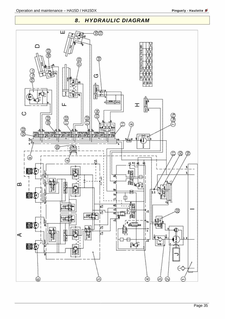
8. HYDRAULIC DIAGRAM
Pinguely - Haulotte Operation and maintenance – HA15D / HA15DX
Page 36
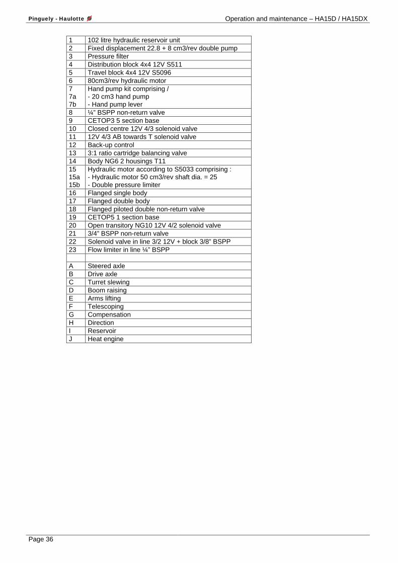
1 102 litre hydraulic reservoir unit 2 Fixed displacement 22.8 + 8 cm3/rev double pump 3 Pressure filter 4 Distribution block 4x4 12V S511 5 Travel block 4x4 12V S5096 6 80cm3/rev hydraulic motor 7 Hand pump kit comprising / 7a - 20 cm3 hand pump 7b - Hand pump lever 8 ¼” BSPP non-return valve 9 CETOP3 5 section base 10 Closed centre 12V 4/3 solenoid valve 11 12V 4/3 AB towards T solenoid valve 12 Back-up control 13 3:1 ratio cartridge balancing valve 14 Body NG6 2 housings T11 15 Hydraulic motor according to S5033 comprising : 15a - Hydraulic motor 50 cm3/rev shaft dia. = 25 15b - Double pressure limiter 16 Flanged single body 17 Flanged double body 18 Flanged piloted double non-return valve 19 CETOP5 1 section base 20 Open transitory NG10 12V 4/2 solenoid valve 21 3/4” BSPP non-return valve 22 Solenoid valve in line 3/2 12V + block 3/8” BSPP 23 Flow limiter in line ¼” BSPP A Steered axle B Drive axle C Turret slewing D Boom raising E Arms lifting F Telescoping G Compensation H Direction I Reservoir J Heat engine
Operation and maintenance – HA15D / HA15DX Pinguely - Haulotte
Page 37
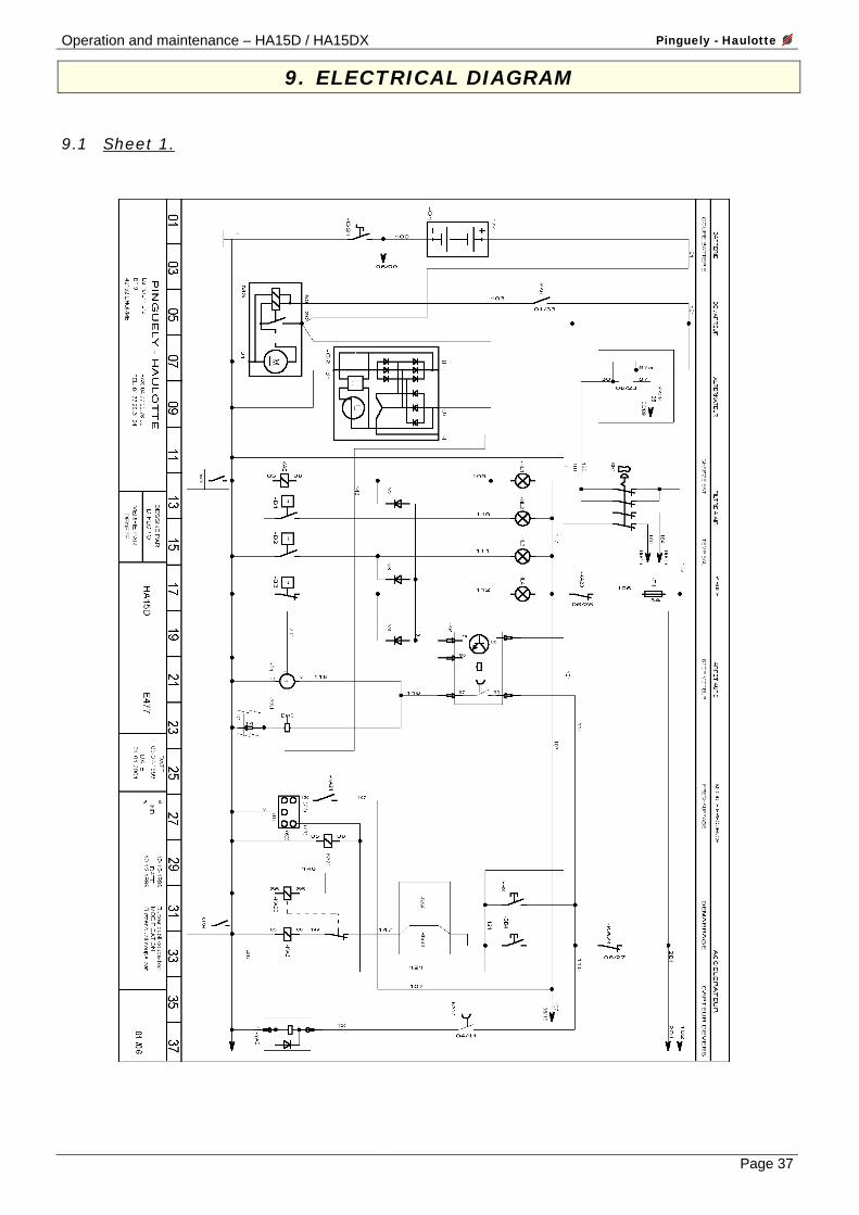
9. ELECTRICAL DIAGRAM
9.1 Sheet 1.

Pinguely - Haulotte Operation and maintenance – HA15D / HA15DX
Page 38
9.2 Sheet 2.

Operation and maintenance – HA15D / HA15DX Pinguely - Haulotte
Page 39
9.3 Sheet 3.
Pinguely - Haulotte Operation and maintenance – HA15D / HA15DX
Page 40
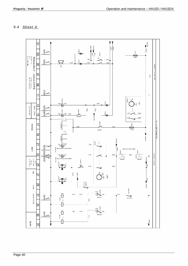
9.4 Sheet 4.
Operation and maintenance – HA15D / HA15DX Pinguely - Haulotte
Page 41
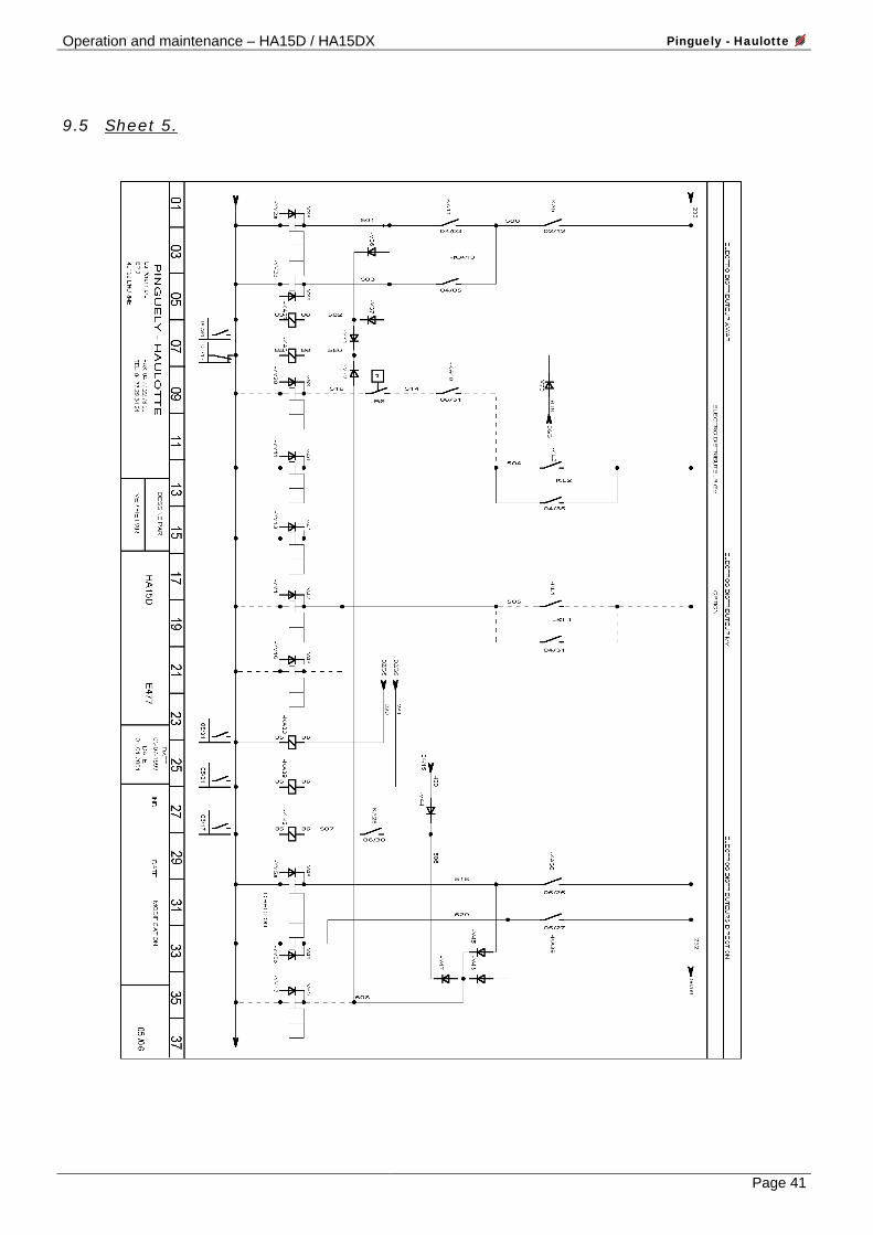
9.5 Sheet 5.
Pinguely - Haulotte Operation and maintenance – HA15D / HA15DX
Page 42
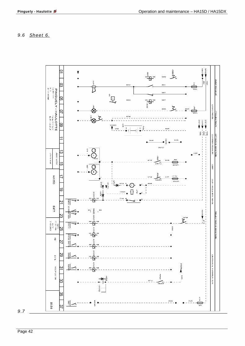
9.6 Sheet 6.
9.7
Operation and maintenance – HA15D / HA15DX Pinguely - Haulotte
Page 43
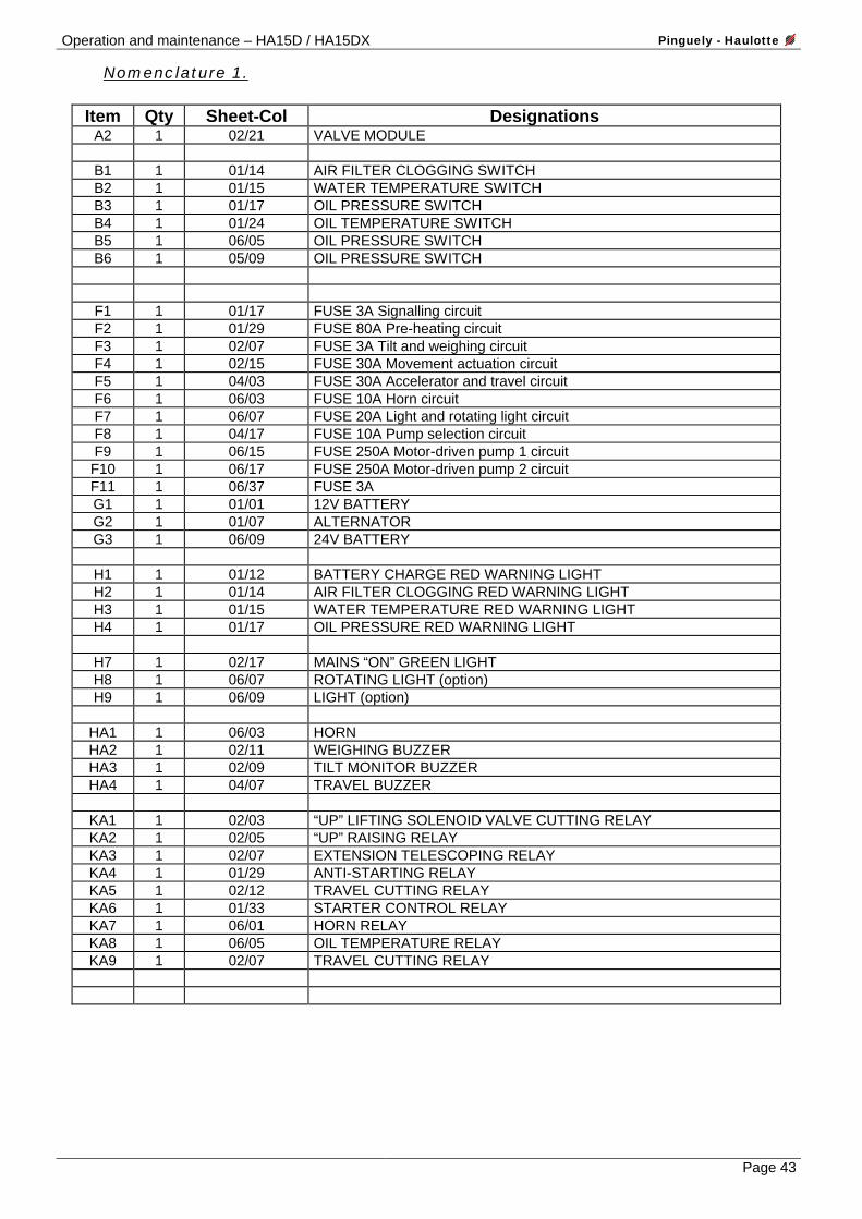
Nomenclature 1.
Item Qty Sheet-Col Designations A2 1 02/21 VALVE MODULE
B1 1 01/14 AIR FILTER CLOGGING SWITCH B2 1 01/15 WATER TEMPERATURE SWITCH B3 1 01/17 OIL PRESSURE SWITCH B4 1 01/24 OIL TEMPERATURE SWITCH B5 1 06/05 OIL PRESSURE SWITCH B6 1 05/09 OIL PRESSURE SWITCH
F1 1 01/17 FUSE 3A Signalling circuit F2 1 01/29 FUSE 80A Pre-heating circuit F3 1 02/07 FUSE 3A Tilt and weighing circuit F4 1 02/15 FUSE 30A Movement actuation circuit F5 1 04/03 FUSE 30A Accelerator and travel circuit F6 1 06/03 FUSE 10A Horn circuit F7 1 06/07 FUSE 20A Light and rotating light circuit F8 1 04/17 FUSE 10A Pump selection circuit F9 1 06/15 FUSE 250A Motor-driven pump 1 circuit F10 1 06/17 FUSE 250A Motor-driven pump 2 circuit F11 1 06/37 FUSE 3A G1 1 01/01 12V BATTERY G2 1 01/07 ALTERNATOR G3 1 06/09 24V BATTERY
H1 1 01/12 BATTERY CHARGE RED WARNING LIGHT H2 1 01/14 AIR FILTER CLOGGING RED WARNING LIGHT H3 1 01/15 WATER TEMPERATURE RED WARNING LIGHT H4 1 01/17 OIL PRESSURE RED WARNING LIGHT
H7 1 02/17 MAINS “ON” GREEN LIGHT H8 1 06/07 ROTATING LIGHT (option) H9 1 06/09 LIGHT (option)
HA1 1 06/03 HORN HA2 1 02/11 WEIGHING BUZZER HA3 1 02/09 TILT MONITOR BUZZER HA4 1 04/07 TRAVEL BUZZER
KA1 1 02/03 “UP” LIFTING SOLENOID VALVE CUTTING RELAY KA2 1 02/05 “UP” RAISING RELAY KA3 1 02/07 EXTENSION TELESCOPING RELAY KA4 1 01/29 ANTI-STARTING RELAY KA5 1 02/12 TRAVEL CUTTING RELAY KA6 1 01/33 STARTER CONTROL RELAY KA7 1 06/01 HORN RELAY KA8 1 06/05 OIL TEMPERATURE RELAY KA9 1 02/07 TRAVEL CUTTING RELAY
Pinguely - Haulotte Operation and maintenance – HA15D / HA15DX
Page 44
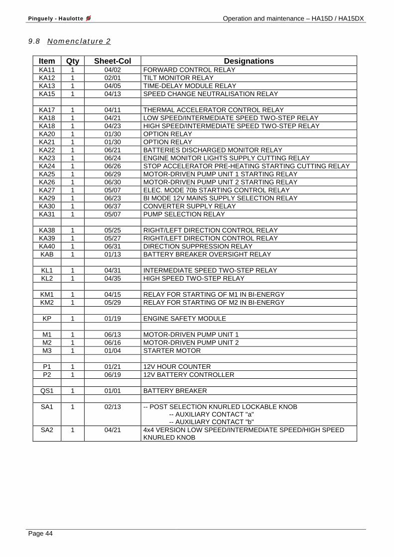
9.8 Nomenclature 2
Item Qty Sheet-Col Designations KA11 1 04/02 FORWARD CONTROL RELAY KA12 1 02/01 TILT MONITOR RELAY KA13 1 04/05 TIME-DELAY MODULE RELAY KA15 1 04/13 SPEED CHANGE NEUTRALISATION RELAY
KA17 1 04/11 THERMAL ACCELERATOR CONTROL RELAY KA18 1 04/21 LOW SPEED/INTERMEDIATE SPEED TWO-STEP RELAY KA18 1 04/23 HIGH SPEED/INTERMEDIATE SPEED TWO-STEP RELAY KA20 1 01/30 OPTION RELAY KA21 1 01/30 OPTION RELAY KA22 1 06/21 BATTERIES DISCHARGED MONITOR RELAY KA23 1 06/24 ENGINE MONITOR LIGHTS SUPPLY CUTTING RELAY KA24 1 06/26 STOP ACCELERATOR PRE-HEATING STARTING CUTTING RELAY KA25 1 06/29 MOTOR-DRIVEN PUMP UNIT 1 STARTING RELAY KA26 1 06/30 MOTOR-DRIVEN PUMP UNIT 2 STARTING RELAY KA27 1 05/07 ELEC. MODE 70b STARTING CONTROL RELAY KA29 1 06/23 BI MODE 12V MAINS SUPPLY SELECTION RELAY KA30 1 06/37 CONVERTER SUPPLY RELAY KA31 1 05/07 PUMP SELECTION RELAY
KA38 1 05/25 RIGHT/LEFT DIRECTION CONTROL RELAY KA39 1 05/27 RIGHT/LEFT DIRECTION CONTROL RELAY KA40 1 06/31 DIRECTION SUPPRESSION RELAY KAB 1 01/13 BATTERY BREAKER OVERSIGHT RELAY
KL1 1 04/31 INTERMEDIATE SPEED TWO-STEP RELAY KL2 1 04/35 HIGH SPEED TWO-STEP RELAY
KM1 1 04/15 RELAY FOR STARTING OF M1 IN BI-ENERGY KM2 1 05/29 RELAY FOR STARTING OF M2 IN BI-ENERGY
KP 1 01/19 ENGINE SAFETY MODULE
M1 1 06/13 MOTOR-DRIVEN PUMP UNIT 1 M2 1 06/16 MOTOR-DRIVEN PUMP UNIT 2 M3 1 01/04 STARTER MOTOR
P1 1 01/21 12V HOUR COUNTER P2 1 06/19 12V BATTERY CONTROLLER
QS1 1 01/01 BATTERY BREAKER
SA1 1 02/13 -- POST SELECTION KNURLED LOCKABLE KNOB
-- AUXILIARY CONTACT "a" -- AUXILIARY CONTACT "b"
SA2 1 04/21 4x4 VERSION LOW SPEED/INTERMEDIATE SPEED/HIGH SPEED KNURLED KNOB
Operation and maintenance – HA15D / HA15DX Pinguely - Haulotte
Page 45
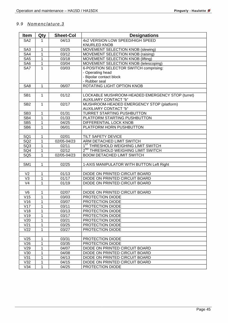
9.9 Nomenclature.3
Item Qty Sheet-Col Designations SA2 1 04/13 4x2 VERSION LOW SPEED/HIGH SPEED
KNURLED KNOB SA3 1 03/25 MOVEMENT SELECTION KNOB (slewing) SA4 1 03/12 MOVEMENT SELECTION KNOB (raising) SA5 1 03/18 MOVEMENT SELECTION KNOB (lifting) SA6 1 03/04 MOVEMENT SELECTION KNOB (telescoping) SA7 1 03/03 6-POSITION SELECTOR SWITCH comprising:
- Operating head - Bipolar contact block - Rubber seal
SA8 1 06/07 ROTATING LIGHT OPTION KNOB
SB1 1 01/12 LOCKABLE MUSHROOM-HEADED EMERGENCY STOP (turret) AUXILIARY CONTACT “b”
SB2 1 02/17 MUSHROOM-HEADED EMERGENCY STOP (platform) AUXILIARY CONTACT “b”
SB3 1 01/31 TURRET STARTING PUSHBUTTON SB4 1 01/33 PLATFORM STARTING PUSHBUTTON SB5 1 04/25 DIFFERENTIAL LOCK KNOB SB6 1 06/01 PLATFORM HORN PUSHBUTTON
SQ1 1 02/01 TILT SAFETY DEVICE SQ2 1 02/05-04/23 ARM DETACHED LIMIT SWITCH SQ3 1 02/11 1ST THRESHOLD WEIGHING LIMIT SWITCH SQ4 1 02/12 2ND THRESHOLD WEIGHING LIMIT SWITCH SQ5 1 02/05-04/23 BOOM DETACHED LIMIT SWITCH
SM1 1 02/25 1-AXIS MANIPULATOR WITH BUTTON Left Right
V2 1 01/13 DIODE ON PRINTED CIRCUIT BOARD V3 1 01/17 DIODE ON PRINTED CIRCUIT BOARD V4 1 01/19 DIODE ON PRINTED CIRCUIT BOARD
V6 1 02/07 DIODE ON PRINTED CIRCUIT BOARD V15 1 03/03 PROTECTION DIODE V16 1 03/07 PROTECTION DIODE V17 1 03/11 PROTECTION DIODE V18 1 03/13 PROTECTION DIODE V19 1 03/17 PROTECTION DIODE V20 1 03/21 PROTECTION DIODE V21 1 03/25 PROTECTION DIODE V22 1 03/27 PROTECTION DIODE
V25 1 03/31 PROTECTION DIODE V26 1 03/35 PROTECTION DIODE V29 1 04/07 DIODE ON PRINTED CIRCUIT BOARD V30 1 04/08 DIODE ON PRINTED CIRCUIT BOARD V31 1 04/13 DIODE ON PRINTED CIRCUIT BOARD V32 1 04/15 DIODE ON PRINTED CIRCUIT BOARD V34 1 04/25 PROTECTION DIODE
Pinguely - Haulotte Operation and maintenance – HA15D / HA15DX
Page 46
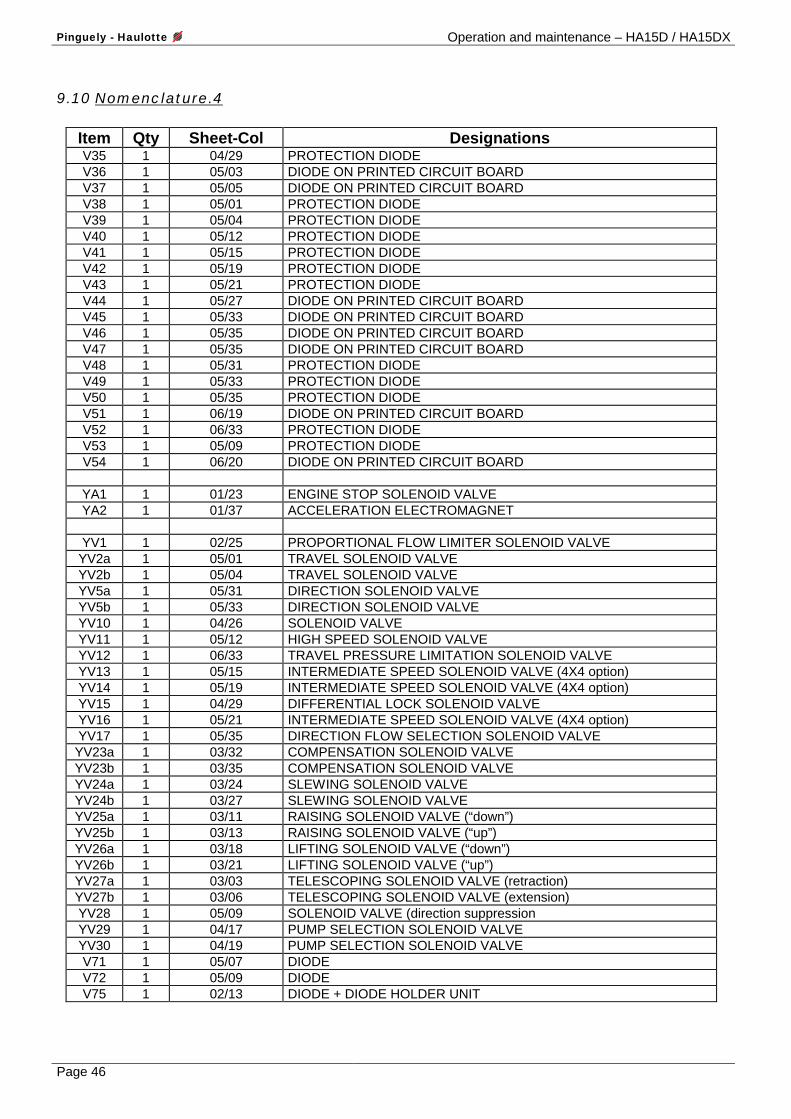
9.10 Nomenclature.4
Item Qty Sheet-Col Designations V35 1 04/29 PROTECTION DIODE V36 1 05/03 DIODE ON PRINTED CIRCUIT BOARD V37 1 05/05 DIODE ON PRINTED CIRCUIT BOARD V38 1 05/01 PROTECTION DIODE V39 1 05/04 PROTECTION DIODE V40 1 05/12 PROTECTION DIODE V41 1 05/15 PROTECTION DIODE V42 1 05/19 PROTECTION DIODE V43 1 05/21 PROTECTION DIODE V44 1 05/27 DIODE ON PRINTED CIRCUIT BOARD V45 1 05/33 DIODE ON PRINTED CIRCUIT BOARD V46 1 05/35 DIODE ON PRINTED CIRCUIT BOARD V47 1 05/35 DIODE ON PRINTED CIRCUIT BOARD V48 1 05/31 PROTECTION DIODE V49 1 05/33 PROTECTION DIODE V50 1 05/35 PROTECTION DIODE V51 1 06/19 DIODE ON PRINTED CIRCUIT BOARD V52 1 06/33 PROTECTION DIODE V53 1 05/09 PROTECTION DIODE V54 1 06/20 DIODE ON PRINTED CIRCUIT BOARD
YA1 1 01/23 ENGINE STOP SOLENOID VALVE YA2 1 01/37 ACCELERATION ELECTROMAGNET
YV1 1 02/25 PROPORTIONAL FLOW LIMITER SOLENOID VALVE YV2a 1 05/01 TRAVEL SOLENOID VALVE YV2b 1 05/04 TRAVEL SOLENOID VALVE YV5a 1 05/31 DIRECTION SOLENOID VALVE YV5b 1 05/33 DIRECTION SOLENOID VALVE YV10 1 04/26 SOLENOID VALVE YV11 1 05/12 HIGH SPEED SOLENOID VALVE YV12 1 06/33 TRAVEL PRESSURE LIMITATION SOLENOID VALVE YV13 1 05/15 INTERMEDIATE SPEED SOLENOID VALVE (4X4 option) YV14 1 05/19 INTERMEDIATE SPEED SOLENOID VALVE (4X4 option) YV15 1 04/29 DIFFERENTIAL LOCK SOLENOID VALVE YV16 1 05/21 INTERMEDIATE SPEED SOLENOID VALVE (4X4 option) YV17 1 05/35 DIRECTION FLOW SELECTION SOLENOID VALVE YV23a 1 03/32 COMPENSATION SOLENOID VALVE YV23b 1 03/35 COMPENSATION SOLENOID VALVE YV24a 1 03/24 SLEWING SOLENOID VALVE YV24b 1 03/27 SLEWING SOLENOID VALVE YV25a 1 03/11 RAISING SOLENOID VALVE (“down”) YV25b 1 03/13 RAISING SOLENOID VALVE (“up”) YV26a 1 03/18 LIFTING SOLENOID VALVE (“down”) YV26b 1 03/21 LIFTING SOLENOID VALVE (“up”) YV27a 1 03/03 TELESCOPING SOLENOID VALVE (retraction) YV27b 1 03/06 TELESCOPING SOLENOID VALVE (extension) YV28 1 05/09 SOLENOID VALVE (direction suppression YV29 1 04/17 PUMP SELECTION SOLENOID VALVE YV30 1 04/19 PUMP SELECTION SOLENOID VALVE V71 1 05/07 DIODE V72 1 05/09 DIODE V75 1 02/13 DIODE + DIODE HOLDER UNIT
Operation and maintenance – HA15D / HA15DX Pinguely - Haulotte
Page 47
10. LABELS
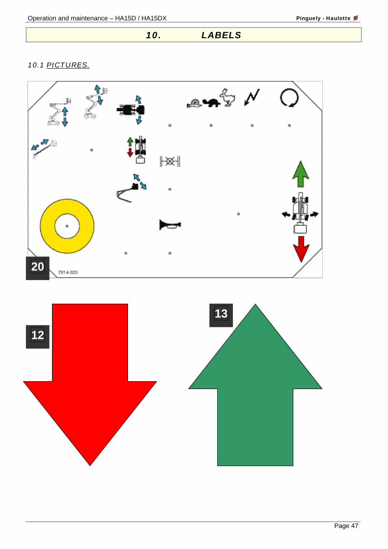
10.1 PICTURES.
13
12
20
Pinguely - Haulotte Operation and maintenance – HA15D / HA15DX
Page 48
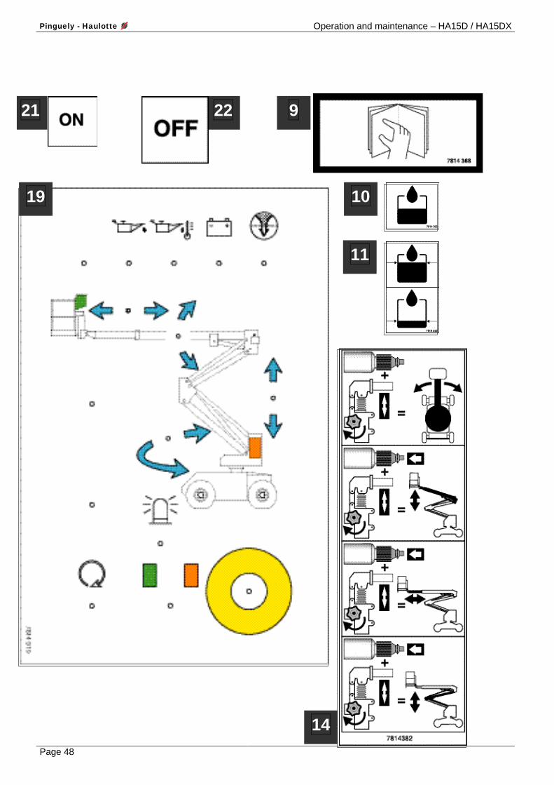
22
10
11
14
19
9 21
Operation and maintenance – HA15D / HA15DX Pinguely - Haulotte
Page 49
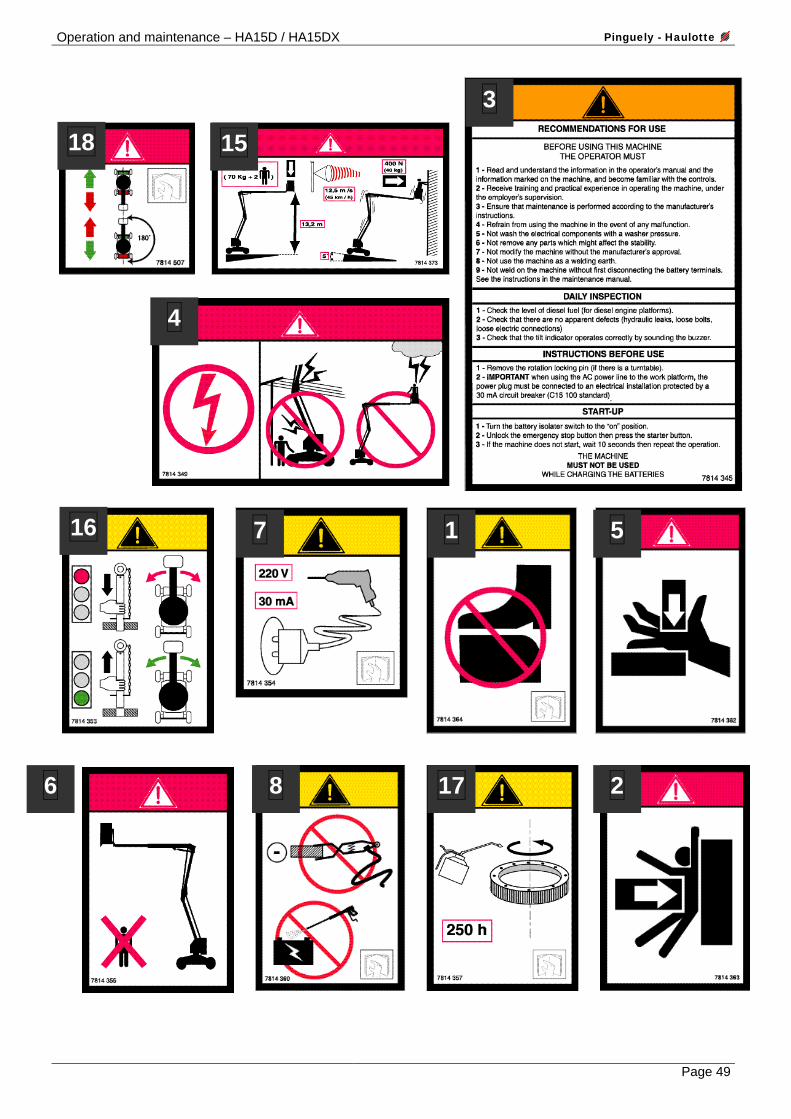
18 15
3
4
16 7 1 5
6 8 17 2

Pinguely - Haulotte Operation and maintenance – HA15D / HA15DX
Page 50
10.2 TABLE OF DESIGNATIONS.
Code Designation 1 02103078143640 Do not put your foot on the cover 2 02103078143630 Risk of crushing (body) 02103078143420 Operating instructions (French) 02103078143430 Operating instructions (Spanish) 02103078143440 Operating instructions (German) 3 02103078143450 Operating instructions (English) 02103078143460 Operating instructions (Italian) 02103078143470 Operating instructions (Dutch) 4 02103078143490 This machine is not isolated. Risk of electrocution. 5 02103078143620 Risk of crushing (hands and fingers) 6 02103078143550 Do not park in the area in which the machine is working. 7 02103078143540 The plug must be connected to (…) 220 V. 8 02103078143600 Do not use as a welding earth. Do not wash… 9 02103078143680 Read the operating and maintenance manual 10 02103078143520 Hydraulic oil 11 02103078143590 Hydraulic oil (high level and low level) 12 02103078137430 Red arrow (backwards) 13 02103078137440 Green arrow (forwards) 14 02103078143820 Use of the hand pump 15 02103078143730 a Floor height + load capacity (small format) 16 02103078143530 Remove the rod before turret rotation 17 02103078143570 Greasing of the rotation ring 18 02103078145070 DANGER – direction of travel 19 02103078143190 Turret unit label 20 02103078143200 Platform unit label 21 02103078142000 ON 22 02103078142010 OFF