Embed Size (px)
Citation preview

OPERATION and MAINTENANCE MANUAL
Version 01.06 CSD RT 80/81 1
OPERATING and MAINTENANCE MANUAL
CRANE TYPE: RTG 6/5/4/WS(E)
WORK No: RT 80/81
DRAWING No: RT 1096
OPERATION and MAINTENANCE MANUAL
Version 01.06 CSD RT 80/81 2
Date of commissioning RT 80/81 ……/…06…/…06
Address of supplier LIEBHERR CONTAINER CRANES LTD Fossa Killarney Co. Kerry Ireland
Product identification Rubber Tyre Gantry Crane Type: RTG 6/5/4/WS(E) Drawing No.: 1096
Document identification Manual number: RT8081 Author: Document version: 01/06
OPERATION and MAINTENANCE MANUAL
Version 01.06 CSD RT 80/81 3
MANUAL SECTIONS
A.
TECHNICAL CHARACTERISTICS PRODUCT DESCRIPTION
B. SAFETY REGULATIONS
C. OPERATING INSTRUCTIONS
AND DRIVER'S MANUAL
OPERATION and MAINTENANCE MANUAL
Version 01.06 CSD RT 80/81 4
C O N T E N T S
THE MANUAL - INTRODUCTION
A.TECHNICAL CHARACTERISTICS PRODUCT DESCRIPTION
B. SAFETY REGULATIONS
B 1. Basic Safety Information B 2. Particular Safety Rules for Operating the Liebherr Container Crane B 3. Safety Instructions B 4. Environmental Protection B 5. Safety for Service, Repair & Maintenance B 6. Emergency Features
C. OPERATING INSTRUCTIONS AND DRIVER'S MANUAL
1. CABIN / YOUR WORKING ENVIRONMENT Driver's cabin/ Drawing/ Equipment
2.Layout of Controls
3.Putting the RTG into service
4.Taking the RTG out of service
5.Operating the RTG
6.Changing the spreader
7.Maintenance Schedule/Lubrication Chart
8. Signs 9. Hand signals
OPERATION and MAINTENANCE MANUAL
Version 01.06 CSD RT 80/81 5
THE MANUAL
The present RTG operating instructions and driver's manual enable the
user/operator to familiarise himself with the safety, function and operation of
the RTG. RTG drivers must not operate this crane without a knowledge and
understanding of all these instructions, which must be carefully adhered to.
Only then can satisfactory and safe operation of the crane be achieved and
the best possible duty and service be obtained from the RTG. It is strongly
recommended that one copy of the operating manual is stored in the driver‟s
cabin or made available to the driver so that at any time, the driver can
consult the manual. The crane must not be operated with any defective or
damaged part. Should the RTG driver note a malfunction of any part, device
or system, he must immediately report it to the appropriate department or
person for investigation.
Any person working on the RTG must follow these operating instructions and
in particular, the safety instructions. Operating staff must have access to
these operating instructions and the mechanical and electrical manuals at
any time, whilst keeping them in easy reach at the site of operation.
It is recommended that both owner and operator should keep a copy at
hand and avail themselves of the information contained therein, in order
to obtain the best possible service from the RTG.
The drivers should be familiar with the contents of the Manual and be
given adequate time to become fully conversant with all aspects of the
RTG before beginning operation for the first time. Particular attention
should also be paid to the section - “Operating Instructions”, as this will
provide valuable information on understanding the RTG. A
comprehensive knowledge of the components will help the driver to get
the maximum usage from the crane operation and enable him to give
valuable information to the maintenance personnel.
Always consult the manual before carrying out any work on the RTG.
The sections dealing with maintenance and lubrication should be
understood and complied with by those responsible for these matters.
The repair of minor faults is usually simple and can be done by any
trained personnel. With the more complicated parts of this machine
however, an inexperienced repairman can cause a considerable amount
of damage. It is suggested therefore, that the repairs be done by a
Liebherr Service Engineer.
Apart from the safety instructions pertaining to this equipment, the rules and
regulations applicable at the operation site, as well as the rules for the
prevention of accidents have to be observed. Such regulations may also
provide for the handling of hazardous substances or for wearing protective
clothing.
Comprehensive Parts Lists are included in the manual for reference when
ordering Spare Parts or replacements. The drawings, photographs
reproduced in the manual are for the purpose of illustrating various points
in the text or to assist in identifying spare parts. They need not
OPERATION and MAINTENANCE MANUAL
Version 01.06 CSD RT 80/81 6
necessarily agree exactly with the actual constructional details of the parts
involved. In order to avoid mistakes, it is advisable to use only the terms
and expressions used in these instructions.
When ordering spare parts, the following information is required: 1. RTG Model 2. RTG Work No. 3. Year of Manufacture 4. Group Heading 5. Description of Part(s) 6. Order No. of Part(s) * 7. Quantity of parts required.
The information in this manual is provided for the benefit of the user and
while every care has been taken to ensure that the information contained
herein is correct, no liability can be accepted for any loss or damage
which may occur due to omission or error, or to misinterpretation of the
contents.
The manufacturer reserves the right to make any such alterations to this
manual, as experience or technical advances may indicate without prior
notice.
* In the case of the computer printed Parts List included in this
Manual, please quote the eight or nine digit figure.
TOOL LIST
RT 80 is provided with a standard set of tools (see tool list TL037),
Liebherr Crane Manuals, including all illustrations contained herein, is copyright protected. Use of these manuals by any third party in departure from the copyright provision is forbidden.
Reproduction, translation, electronic or photographic archiving or alteration requires the express written consent of Liebherr Container Cranes Ltd.
The manuals contain regulations, instructions and technical specifications which may neither completely nor partly be copied, distributed or otherwise communicated.
Violating the copyright will be prosecuted. Liebherr Container Cranes Ltd. reserves the right to make any technical
changes that serve for the purposes of technical progress.
OPERATION and MAINTENANCE MANUAL
Version 01.06 CSD RT 80/81 7
A. TECHNICAL CHARACTERISTICS
PRODUCT DESCRIPTION
RTG TYPE 6/5/4/WS(E) CRANE WORK NOS. RT 80/81
DRAWING NO.: RT 1096
RTG GENERAL INFORMATION
LIEBHERR RUBBER TYRED GANTRY CRANE MODEL RTG 6/5/4/WS(E) is destined for the stacking and handling of ISO containers size 20‟ and 40‟ in container terminals and designed to stack one over five containers (max. height 9‟ 6”) and to span six rows of container plus one truck lane. A telescopic spreader is provided, this is attached directly to the ropes. The spreader is capable of handling 20 ft. and 40 ft. containers in single lift mode. Four fixed side guides are provided, these also allow the handling of „pallet wide‟ containers. The crane is designed for independent operation with diesel generator power source mounted on the RTG. The Liebherr RTG can perform the following operations:
Transfer a 40.6 tonne container from a stack or ground position to a truck chassis, railroad flat car or a ground position and vice versa. Simultaneous hoisting, trolley-travelling and “inching” in gantry travel direction is possible with a container load.
Gantry travel, at reduced speed and trolley travel while carrying loads up to 40.6 tonnes.
Gantry travel, at full speed and trolley travel with empty spreader.
Turn its wheels through 90º for the purpose of travelling to other stack lanes or to other designated areas, without load, at a reduced speed.
Set its wheels to perform a 180º spin turn about its own vertical axis at a reduced speed.
The RTG is accessible via ladders, stairs and platforms for easy access to driver‟s cabin, main beam, trolley and maintenance points.
The crane structure and its mechanical and electrical equipment is designed to allow safe crane operation up to a wind speed of 72 km/h.

OPERATION and MAINTENANCE MANUAL
Version 01.06 CSD RT 80/81 8
OPERATION and MAINTENANCE MANUAL
Version 01.06 CSD RT 80/81 9
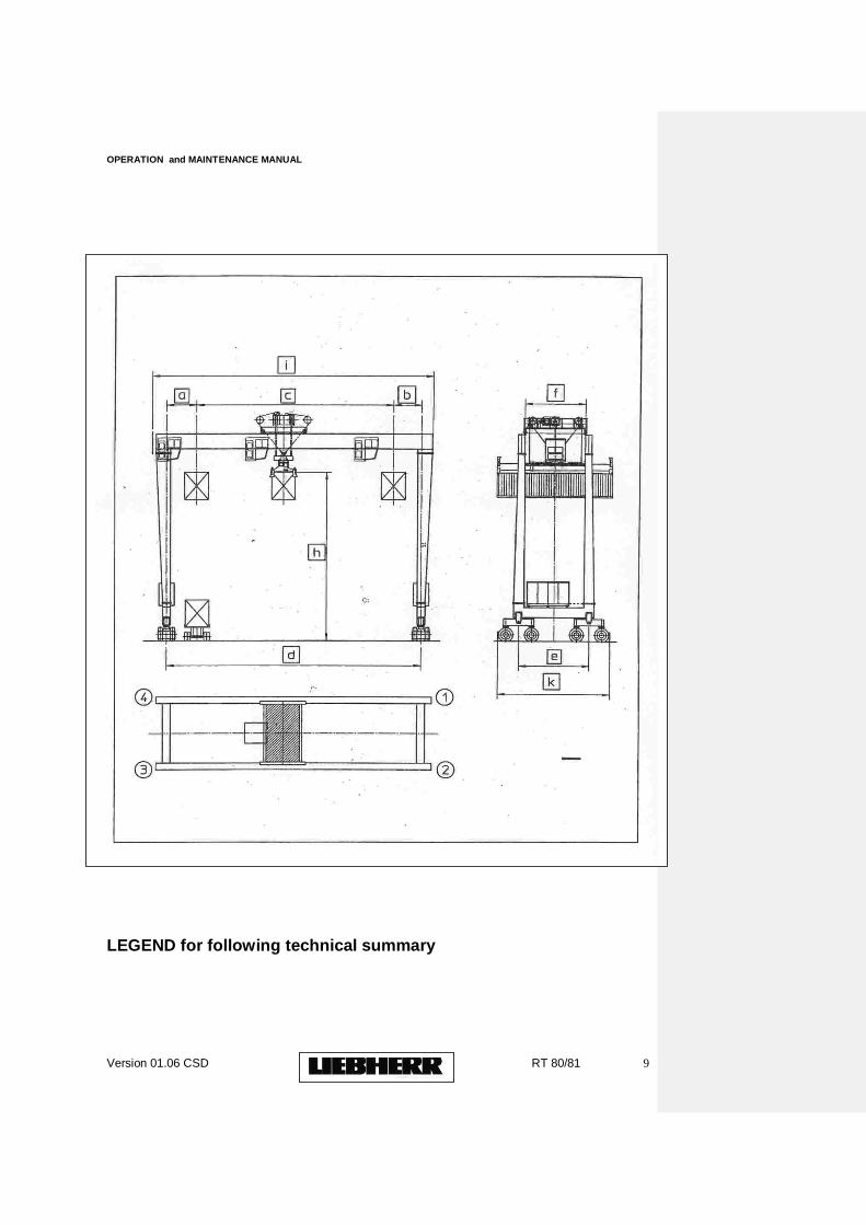
LEGEND for following technical summary
OPERATION and MAINTENANCE MANUAL
Version 01.06 CSD RT 80/81 10
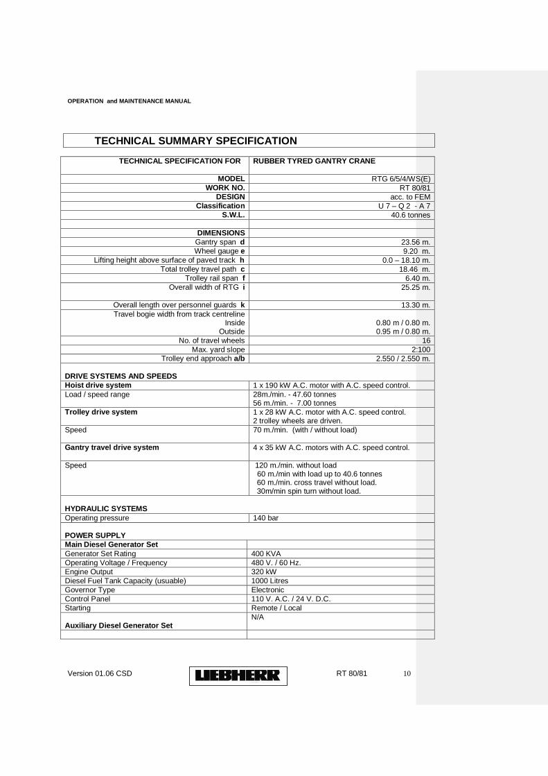
TECHNICAL SUMMARY SPECIFICATION
TECHNICAL SPECIFICATION FOR
RUBBER TYRED GANTRY CRANE
MODEL RTG 6/5/4/WS(E) WORK NO. RT 80/81
DESIGN acc. to FEM Classification U 7 – Q 2 - A 7
S.W.L. 40.6 tonnes
DIMENSIONS
Gantry span d 23.56 m. Wheel gauge e 9.20 m.
Lifting height above surface of paved track h 0.0 – 18.10 m. Total trolley travel path c 18.46 m.
Trolley rail span f 6.40 m. Overall width of RTG i 25.25 m.
Overall length over personnel guards k 13.30 m.
Travel bogie width from track centreline Inside
Outside
0.80 m / 0.80 m. 0.95 m / 0.80 m.
No. of travel wheels 16
Max. yard slope 2:100 Trolley end approach a/b 2.550 / 2.550 m.
DRIVE SYSTEMS AND SPEEDS
Hoist drive system 1 x 190 kW A.C. motor with A.C. speed control.
Load / speed range 28m./min. - 47.60 tonnes 56 m./min. - 7.00 tonnes
Trolley drive system 1 x 28 kW A.C. motor with A.C. speed control. 2 trolley wheels are driven.
Speed
70 m./min. (with / without load)
Gantry travel drive system 4 x 35 kW A.C. motors with A.C. speed control.
Speed 120 m./min. without load 60 m./min with load up to 40.6 tonnes
60 m./min. cross travel without load. 30m/min spin turn without load.
HYDRAULIC SYSTEMS
Operating pressure 140 bar POWER SUPPLY
Main Diesel Generator Set
Generator Set Rating 400 KVA
Operating Voltage / Frequency 480 V. / 60 Hz.
Engine Output 320 kW
Diesel Fuel Tank Capacity (usuable) 1000 Litres
Governor Type Electronic
Control Panel 110 V. A.C. / 24 V. D.C.
Starting Remote / Local
Auxiliary Diesel Generator Set
N/A
OPERATION and MAINTENANCE MANUAL
Version 01.06 CSD RT 80/81 11
B SAFETY
This chapter contains
B 1. Basic Safety Information
B 2. Particular Safety Rules for Operating the Liebherr Container Crane
B 3. Safety Instructions
B 4. Environmental Protection
B 5. Safety for Service, Repair & Maintenance
B 6. Emergency Features
OPERATION and MAINTENANCE MANUAL
Version 01.06 CSD RT 80/81 12
B 1.
BASIC SAFETY INFORMATION
WARNING It is important to read and understand all safety instructions
provided in our LCC container crane manuals. Improper operation or maintenance could result in a serious
accident, or damage to the equipment, causing injury or death.
The Liebherr RTG 6/5/4/WS(E) has been built in accordance with relevant standards, safety rules and regulations. Nevertheless failure to observe safe operating procedures may constitute a risk to life and limb of port personnel or third parties, or could cause damage to the RTG or other material. The Liebherr RTG must only be used in perfect condition in accordance with its designated use and the instructions set out in the operation manual and only by safety conscious persons who are fully trained and aware of the risks involved in operating the RTG. Any functional disorders, especially those affecting the safety of the RTG should therefore be rectified immediately. The RTG is designed exclusively for stacking and loading 20/40ft. ISO containers and always for straight vertical lifts. Using the RTG for purposes other than those mentioned above (such as for pulling and moving of lorries and other loads) is considered contrary to its designated use. The manufacturer cannot be held liable for any damage resulting from such use and the risk of misuse lies entirely with the user. The operating instructions must always be at hand at the place of use of the RTG. Personnel entrusted with work on the RTG must have read the operating instructions and in particular the chapter on safety before starting to work. Reading the instructions after work has begun is too late. This applies especially to persons working only occasionally on the machine e.g. during setting up or maintenance. Liebherr Container Cranes provides copies of the RTG manual for each station involved in the operation, service, maintenance and spare parts organisation (if desired) according to the customer‟s job organisation, working sequences or personnel entrusted with the work or maintenance. The copy is simple to read and for ease of use, reference symbols are applied to lead the reader to the relevant section of the manual, or to lead to a more detailed section with further information.
OPERATION and MAINTENANCE MANUAL
Version 01.06 CSD RT 80/81 13
In addition to the operating instructions, the user should observe all other generally applicable legal and other mandatory regulations relevant to accident prevention and environmental protection. These compulsory regulations may also deal with the handling of hazardous substances issuing and/or wearing of personal protective equipment or traffic regulations. Weather forecast should be monitored by the port operators to protect the crane from storm conditions. Note the operating wind speed mentioned in manual. Every lifting operation should be properly carried out by a trained and competent person and in a safe manner and appropriately supervised. Safe access and means of emergency escape should be maintained in good condition for the driving position(s) of the crane and for inspection, maintenance and repair of the crane. Records should be maintained for each crane that are sufficient to enable the condition of the crane to be determined and its fitness for further operation to be properly assessed.
OPERATION and MAINTENANCE MANUAL
Version 01.06 CSD RT 80/81 14
B 2.
PARTICULAR SAFETY RULES FOR OPERATING THE LIEBHERR RTG The following general safety rules for operating the RTG are drawn up in the event of no local regulations being in force. If local regulations are in force concerning RTG operation, then these should be followed carefully and adhered to.
The importance of these points cannot be over-emphasised as the
accident-free, efficient operation and satisfactory functioning of the RTG
and all its components is entirely dependent on their observance. A false
sense of security on the part of the RTG operator can lead to serious
trouble and sometimes serious accidents.
It is vital that the RTG is handled and operated gently and without
aggression. In this way, it will be seen that the loading and
unloading operation can be completed faster and without fuss and
can reduce the wear on the RTG and its parts and will be far less
tiring on the driver, other RTG operators and maintenance
personnel.
2.1.1 QUALIFICATIONS OF RTG OPERATOR
Only reliable personnel of recognised ability, familiar with the mechanical
and electrical characteristics of the RTG, instructed in safety codes and
standards applicable in crane operation, may drive and operate the RTG.
The operator must be over eighteen years of age, be mature in attitudes
and responses, be in good health and his background should include both
training and experience in the operation of this type of equipment. He
must possess a general knowledge of the RTGs construction, be familiar
with details of power supply and electricity, hydraulics, safety devices,
emergency cutouts, emergency exits, fire extinguishers, etc.
2.1.2 RESPONSIBILITIES OF RTG OPERATOR
A knowledge of technical terms, parts‟ identification and maintenance is
required for this work. The RTG operator is responsible for seeing that
the RTG is in a safe and serviceable condition and has its maintenance
completed at the recommended intervals (lubrication, etc.). He must have
the operating instructions at his disposal at all times. He must check all
parts, which are subject to, wear and he must report all cases of
excessive wear without delay to the site foreman or supervisor. He must
immediately report any damage to ropes, or any mechanical, electrical or
structural faults. The RTG operator must be satisfied with the functioning
of all brakes, limit switches, safety devices, etc. He must be satisfied that
the RTG is properly serviced at the recommended intervals.
OPERATION and MAINTENANCE MANUAL
Version 01.06 CSD RT 80/81 15
2.1.3 HANDLING OF DEFECTS/FAULTS
The RTG operator must keep a record of any defects noticed in a
logbook. He must also report any defects to the supervisor or foreman
without delay, as well as advise the relief operator when changing shifts.
The supervisor or foreman must be informed immediately should the
relieving operator fail to report on site on time.
2.1.4 “NO STORAGE” OF WASTE
The storing of rags, waste, oil or any combustible material in any part of
the RTG must be prohibited.
2.1.5 NATIONAL DIRECTIVES
National directives, local by-laws and safety procedures concerning the
operation of RTGs, if available and in force, must be posted in the
operator‟s cabin or elsewhere - as necessity indicates.
2.1.6 “TRANSPORT” OF PERSONNEL
Personnel may not be transported on containers, spreaders or any lifting
equipment.
2.1.7 “NO LOAD” OVER PERSONNEL
Hoisting loads over personnel on the ground is strictly forbidden. All
ground personnel should wear high visibility jackets.
2.1.8 ACCESS TO OPERATING RTG
During operation, the RTG may only be entered or exited after the RTG
operator has been informed and the RTG brought to a standstill.
The cabin platform may be entered and exited through the safety gates
after the RTG operator has been informed and the trolley has been
brought to a stand still with both entry gates in the lined up position.
2.1.9 WORKING UNDER OPERATING RTG
Working under the operating RTG or within the travelling area of the
RTG is strictly forbidden. If it is imperative that work in this area has to
be done during the RTG operation, then the driver has to be consulted
directly by people carrying out this work.
2.1.10 REMOVAL OF TOOLS FROM RTG
Tools or other objects must not be left lying on the trolley tracks or any
part of the RTG structure. They can severely damage the RTG and
cause serious or fatal injury to personnel involved in the RTG operation.
OPERATION and MAINTENANCE MANUAL
Version 01.06 CSD RT 80/81 16
2.1.11 OBSERVE THE OPERATION OF OTHER RTG‟S
The utmost care must be taken when travelling towards adjacent RTGs.
2.1.12 RTG TRAVELLING
Great care must be taken during normal RTG travel motion, cross travel
and spin turn that the run ways are free of all obstacles, machinery,
vehicles, personnel etc. A minimum clearance between the RTG and
the container stacks must be maintained during normal RTG travel.
Lateral Anti-Collision sensors are provided at all corners to ensure that
the RTG does not collide with the stack or other objects.
LACK OF CONSTANT CARE DURING THIS OPERATION CAN LEAD
TO SERIOUS CONSEQUENCES FOR MACHINERY AND
PERSONNEL
2.1.13 RTG AND TRUCK TO BE STATIONARY
When loading or unloading trucks, it is imperative that both the truck and
the RTG are stationary.
2.1.14 LOAD LIFTING, LOAD MOVEMENT
The load must be raised clearly above any surrounding obstacle before
any attempt to travel is made. The operator must watch the load and
spreader at all times during operation.
2.1.15 CONTAINERS TO BE UNLOCKED
If loads are taken directly from trucks, the RTG driver must ensure that
the truck is completely at rest and that any devices securing the
container to the truck body are disengaged. Containers to be lifted must
be completely unlocked and not in a “jammed” condition.
2.1.16 NO “DRAGGING” OF LOAD
The loads must always be lifted vertically. No attempt must be made to
“drag” the load by the use of the trolley or long travel.
2.1.17 LIFTING CAPACITY OF RTG
The overload device should not be treated as an operational control
device.
THE RTG MAY NOT BE LOADED ABOVE ITS RATED MAXIMUM
CAPACITY.
OPERATION and MAINTENANCE MANUAL
Version 01.06 CSD RT 80/81 17
Safe Working Load under the BROMMA Telescopic Spreader:
40.60 Tonnes. = 40,600 kg in single lift mode.
The data provided on the Safe Working Load (S.W.L.) signs fitted to the
RTG and the lifting equipment must be clearly legible and clearly
understood at all times.
2.1.18 LIFTING EQUIPMENT
Whereas the lifting equipment provided with this RTG is designed for
heavy-duty operation, it is imperative that excessive impact loadings are
not applied.
It is therefore essential that proper deceleration is applied to the hoist
system before the lifting equipment -loaded or unloaded- comes into
contact with any other item.
2.1.19 COMMUNICATION WITH GROUND PERSONNEL
Hand signals should be agreed between RTG operators and ground
personnel. If required, these signals can be used to direct the RTG
operator. If local regulations regarding signals are in force, then these
should be used. Only responsible and competent personnel who are
thoroughly familiar with the signalling system in use should be allowed
to give these signals.
The agreed signals should be posted at strategic locations in the cabin,
at ground level and other desirable locations, e.g. rest rooms,
workshops, etc.
See last page of manual detailing signalling recommended.
2.1.20 SAFETY DEVICES
The RTG driver should ensure that all safety devices are operating
properly. These should be tested frequently. He should also ensure
that all protection systems to the mechanical and electrical equipment
are properly fitted, e.g. covers over rotating parts, guards, etc.
2.1.21 MOTION LIMIT SWITCHES
Pre and Final stop limit switch systems are provided to protect RTG and
driver in the event of an error in driver‟s judgement. These switch
systems should not be considered as normal operational switches and
drivers must operate with due caution when approaching limit switch
zones.
NOTE: (i) All motion limit switch systems must be tested for cor-
rect operation prior to commencement of each driver‟s shift, without
load on lifting equipment.
OPERATION and MAINTENANCE MANUAL
Version 01.06 CSD RT 80/81 18
(ii) The RTG must not be operated should any of the limit switch
systems be defective without prior approval of the terminal‟s safety
engineers.
2.1.22 BUFFERS
All trolley buffers, including their support structures, should be kept in
good condition. Note that these buffers are considered as emergency
stops only in case pre-limit and final-limit switch system fails.
2.1.23 EMERGENCY
If any trouble occurs during the RTG operation, then one of the
emergency buttons should be pressed. See Section 4.2 for the location
of the emergency stops.
2.1.24 SAFE PARKING OF RTG
The driver must not leave the RTG without ensuring that the RTG is
properly parked. (See Section “TAKING THE RTG OUT-OF-
SERVICE”).
The normal out-of-service trolley parking position is with the trolley at the
extreme end approach on the main entry side. As a minimum (if wind
speeds are below 72 km/h), the travel wheels must be turned 45º at all
RTG corners to their parking positions.
2.1.25 OPERATING WIND SPEED
It should be noted once again that THIS RTG SHOULD NOT BE
OPERATED IN WIND SPEEDS EXCEEDING 72 km/h (= 45 m.p.h.).
The RTG must be taken out of service at such a speed and the parking
systems properly applied.
(See Section “TAKING THE RTG OUT-OF-SERVICE”).
2.1.26 WARNING SIGNS AND NOTICES
At various locations on the RTG and its lifting equipment, LIEBHERR
has provided Warning Signs in accordance with the RTG specification
and which are considered by LIEBHERR to meet the requirements in
this respect. However, if any local safety regulations and requirements
applicable for this RTG require additional Warning Signs, Notices,
Regulations, Recommendations, or otherwise, then such requests must
be made known to LIEBHERR at the latest at RTG commissioning date.
Arrangements will then be made by LIEBHERR to meet these requests.
It is the purchaser‟s responsibility to permit access to the RTG to
authorised personnel only, and/or the working areas of the RTG. The
purchaser/user must also ensure that this is strictly adhered to at all
times. If any of the signs provided become dislocated or damaged, it is
important that they are replaced or repaired immediately.
OPERATION and MAINTENANCE MANUAL
Version 01.06 CSD RT 80/81 19
2.1.27 ADVERSE WEATHER CONDITIONS
Very high temperatures, storms, very low temperatures, snow, ice,
prolonged and heavy rainfall, thunder storms, extreme sudden changes
in temperature and other natural phenomena may effect the condition of
the structural components, the electrical and mechanical equipment and
the safety systems. Due consideration should be given to this.
Depending on the severity and abnormality of such adverse weather
conditions, appropriate action should be arranged for before putting the
RTG into operation again.
2.1.28 NO DRAW STRINGS
It is recommended that personnel entering the RTG do not wear jackets
or other garments with draw strings, as they can get entangled in parts
of the machinery. This may lead to situations causing serious or fatal
injury.
OPERATION and MAINTENANCE MANUAL
Version 01.06 CSD RT 80/81 20
B 3.
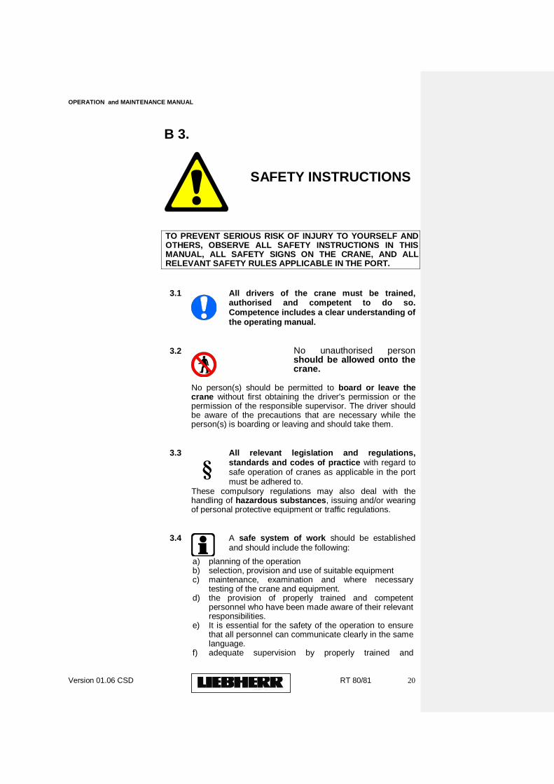
SAFETY INSTRUCTIONS
TO PREVENT SERIOUS RISK OF INJURY TO YOURSELF AND OTHERS, OBSERVE ALL SAFETY INSTRUCTIONS IN THIS MANUAL, ALL SAFETY SIGNS ON THE CRANE, AND ALL RELEVANT SAFETY RULES APPLICABLE IN THE PORT.
3.1
All drivers of the crane must be trained, authorised and competent to do so. Competence includes a clear understanding of the operating manual.
3.2
No unauthorised person should be allowed onto the crane.
No person(s) should be permitted to board or leave the
crane without first obtaining the driver's permission or the permission of the responsible supervisor. The driver should be aware of the precautions that are necessary while the person(s) is boarding or leaving and should take them.
3.3
§
All relevant legislation and regulations, standards and codes of practice with regard to safe operation of cranes as applicable in the port must be adhered to.
These compulsory regulations may also deal with the handling of hazardous substances, issuing and/or wearing of personal protective equipment or traffic regulations.
3.4
A safe system of work should be established and should include the following:
a) planning of the operation b) selection, provision and use of suitable equipment c) maintenance, examination and where necessary
testing of the crane and equipment. d) the provision of properly trained and competent
personnel who have been made aware of their relevant responsibilities.
e) It is essential for the safety of the operation to ensure that all personnel can communicate clearly in the same language.
f) adequate supervision by properly trained and
OPERATION and MAINTENANCE MANUAL
Version 01.06 CSD RT 80/81 21
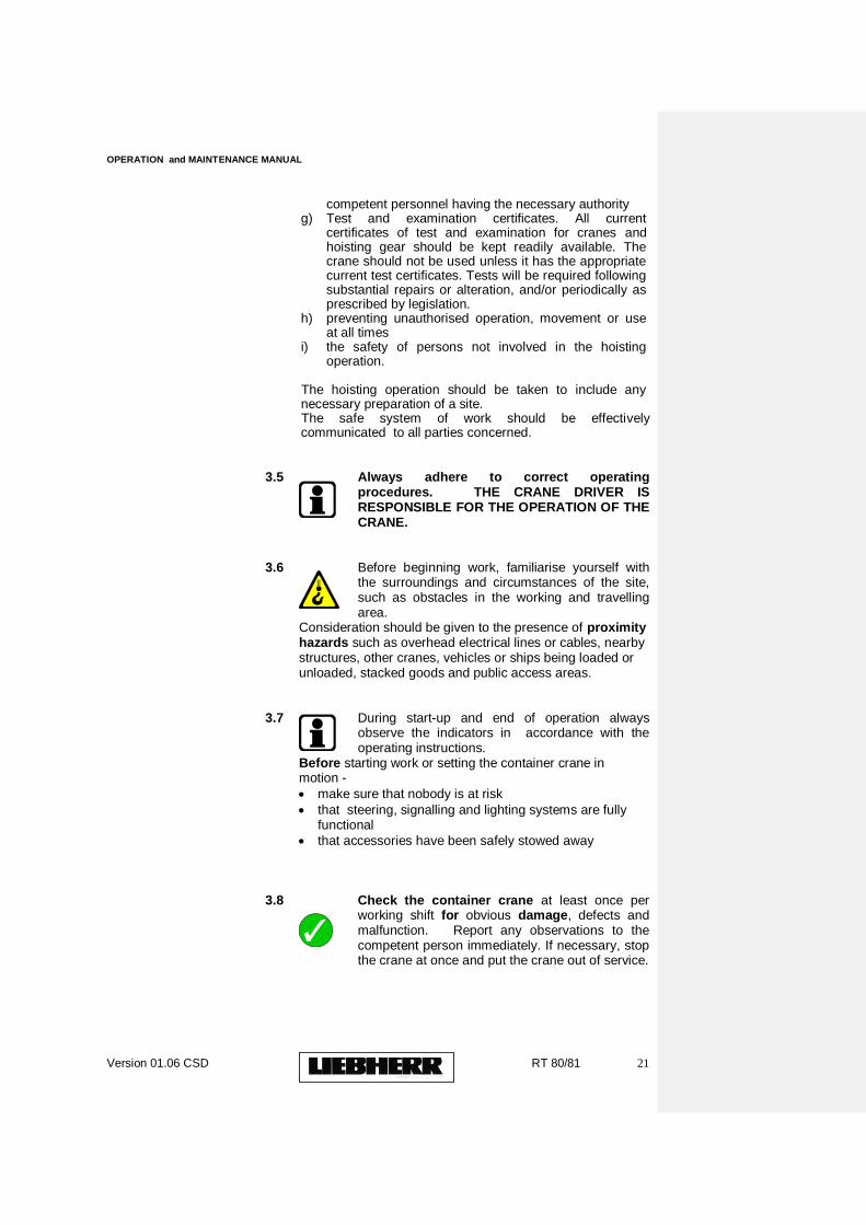
competent personnel having the necessary authority g) Test and examination certificates. All current
certificates of test and examination for cranes and hoisting gear should be kept readily available. The crane should not be used unless it has the appropriate current test certificates. Tests will be required following substantial repairs or alteration, and/or periodically as prescribed by legislation.
h) preventing unauthorised operation, movement or use at all times
i) the safety of persons not involved in the hoisting operation.
The hoisting operation should be taken to include any necessary preparation of a site. The safe system of work should be effectively communicated to all parties concerned.
3.5
Always adhere to correct operating procedures. THE CRANE DRIVER IS RESPONSIBLE FOR THE OPERATION OF THE CRANE.
3.6
Before beginning work, familiarise yourself with the surroundings and circumstances of the site, such as obstacles in the working and travelling area.
Consideration should be given to the presence of proximity hazards such as overhead electrical lines or cables, nearby structures, other cranes, vehicles or ships being loaded or unloaded, stacked goods and public access areas.
3.7
During start-up and end of operation always observe the indicators in accordance with the operating instructions.
Before starting work or setting the container crane in motion -
make sure that nobody is at risk
that steering, signalling and lighting systems are fully functional
that accessories have been safely stowed away
3.8
Check the container crane at least once per working shift for obvious damage, defects and malfunction. Report any observations to the competent person immediately. If necessary, stop the crane at once and put the crane out of service.
OPERATION and MAINTENANCE MANUAL
Version 01.06 CSD RT 80/81 22
3.9
Check and observe safety instructions and warning signs attached to container crane and their legibility.
3.10
Only use the Container Crane in a safe and reliable condition. Damaged hoisting equipment, ropes, spreaders, etc. must not be used but repaired or discarded as appropriate. An inspection and preventive maintenance programme must be put in place.
3.11
Never exceed the Safe Working Load (SWL) of the crane or lifting equipment. ALL lifting equipment must be clearly marked with its SWL and used for its intended purpose only. The SWL of each piece of lifting equipment must ALWAYS be MORE THAN the weight of the load to be lifted.
3.12
Avoid any operation that might be a risk for the stability of the container crane.
3.13
ENSURE that all lifting or hoisting equipment is SECURED to the crane.
3.14
NEVER WALK UNDER A SUSPENDED LOAD. NEVER LIFT A LOAD OVER ANY PERSON.
3.15
Appropriate site access / prohibition rules should be put into place in the port to ensure that no person is or may be struck by the crane or load.
3.16
NEVER leave a load suspended when the crane is unattended.
3.17
Ensure that there is an unimpeded view of the operation or otherwise have a signaller with a suitable system of communication.
OPERATION and MAINTENANCE MANUAL
Version 01.06 CSD RT 80/81 23
3.18
In conditions of poor visibility and after dark always switch on the lighting systems.
3.19
Before leaving the drivers seat always secure the machine against inadvertent operation, movement and unauthorised use.
3.19
Personnel working on the crane should be familiar with the location and use of fire extinguishers, and evacuation procedure. See Section Emergency Features B 6. (Refer to section Emergency Features Section B 6 of this manual.)
3.20
ELECTRICITY - DANGER! Electricity can kill ! Lethal voltages may be present in some of the equipment referred to in our manuals.
a) In the unlikely event that the container crane comes into contact with a live wire
do not leave the cabin
drive the machine out of hazard zone
warn others against approaching or touching the container crane
have the live wire de-energised
do not leave the machine until damage line has been de-energised.
(b) Access to electric terminal boxes, circuits, etc., is prohibited to all except personnel who are trained, competent and authorised to do so. (Refer to maintenance section below)
3.21
In the event of safety-relevant modifications or changes in the behaviour of the crane stop the container crane immediately and report the malfunction to the competent authority/person.
3.21
Never make any modification, additions or conversions, which might affect safety without the supplier‟s approval. This also applies to the installation and adjustment of safety devices and valves as well as to welding work on load-bearing elements. Modifications may require the crane to be re-tested and certified.
OPERATION and MAINTENANCE MANUAL
Version 01.06 CSD RT 80/81 24
B 4.
ENVIRONMENTAL PROTECTION
Your container crane has been manufactured with the objective of environmental protection, pollution prevention and continual improvement. The manufacturing process has been in accordance with the philosophy of Best Available Technology Not Entailing Excessive Cost (BATNEEC) with strict controls over environmental impact. The user of this crane is encouraged to continue this philosophy.
4.1 When filling or draining oil reservoirs, diesel tanks and
radiators, care should be taken to contain all spillages. 4.2 Regular preventive maintenance, e.g. cleaning/changing oil
filters, will prolong the life of the equipment and fluid and minimise the energy required to operate crane efficiently.
4.3 All waste arising from the maintenance and upkeep of the
crane should be disposed of in accordance with local waste regulations. Recycling is recommended:
Waste Electrical & Electronic Equipment
Oils and grease
Touch-up paints & solvents
Lighting
Etc.
OPERATION and MAINTENANCE MANUAL
Version 01.06 CSD RT 80/81 25
B 5.
SAFETY FOR SERVICE, REPAIR & MAINTENANCE
Before attempting maintenance work on any part of the crane or its components, the LCC operation and maintenance
instructions, and in particular the safety warnings, must be read and clearly understood.
5.1 SERVICE AND REPAIR.
Spare parts must comply with the technical requirements specified by the manufacturer. Spare parts from original parts manufacturers and/or suppliers can be relied on.
Replace hydraulic hoses within stipulated and appropriate intervals even if no safety-relevant defects have been detected.
Preventive Maintenance
Adhere to prescribed intervals or those specified in the operating instructions for routine checks and inspections.
5.2 SERVICE/MAINTENANCE
All maintenance work (mechanical, hydraulic or electrical) must only be carried by personnel who are qualified and competent to do so, the maintenance personnel should be fully conversant with the machinery they are required to maintain and its hazards and be familiar with the procedures and precautions recommended. The maintenance personnel should be responsible for maintaining the crane and ensuring its safe and satisfactory operation. They should carry out all necessary maintenance in accordance with the manufacturer's maintenance manual and within the safe system of work.
OPERATION and MAINTENANCE MANUAL
Version 01.06 CSD RT 80/81 26
The operation of a “PERMIT-TO-WORK” system is strongly recommended by LCC. An effective permit to work system will ensure that the crane is physically incapable of movement and circuits are isolated before written authority is given to the person who is to undertake the work.
Adhere to prescribed adjusting, maintenance and inspection procedures and intervals and those specified in the operating instructions for routine checks and inspections.
Ensure that maintenance areas are adequately secured.
The container crane must be secured against inadvertent starting by:
Return control levers to “0” and turn the start key to “0” position, respectively consult the driver's or operation manual.
Carry out maintenance and repair only if crane is out of service. Before returning the crane to service ensure that all guards, safety devices, etc., are in good condition and correctly installed.
Never use machine parts as climbing aid. If not standing firmly on a platform/walkway wear a safety harness anchored securely when carrying out maintenance at a height greater than 2 metres.
Keep all handles, steps, handrails, platforms, landings and ladders clean and free from snow and ice (where applicable)
Clean the container crane of any traces of oil, fuel or preservatives before maintenance/repair and examine all fuel, lubricant and hydraulic fluid lines for leaks, loose connections, chafe marks and damage in order to rectify them without delay.
Tighten bolted connections that might have been loosened during maintenance/repair.
Ensure that all consumables and replaced parts are disposed of safely and with minimum environmental impact.
OPERATION and MAINTENANCE MANUAL
Version 01.06 CSD RT 80/81 27
When working with chemicals (paint, oils, grease, etc.) adequate precaution should be taken as detailed on Material Safety Data Sheets.
ELECTRICAL - Work on electrical system or equipment should be carried out by a competent electrician only according to maintenance/service and repair handbook.
The electrical equipment of the crane is to be inspected and checked at regular intervals.
Fire extinguishers should be scheduled for periodic inspection and be renewed as necessary.
Suitable Personal Protective Equipment should be used as required.
Documented inspection and maintenance records should be kept.
5.3 HYDRAULIC EQUIPMENT
BASIC SAFETY WHEN USING HYDRAULICS
Check all lines, hoses and connections for leaks and obvious damage. Splashed oil may cause injury and fire.
Depressurise all system sections before loosening/removal of pressure pipes and/or connections in accordance with the specific instructions for carrying out any repair work.
Ensure that all relevant machinery is switched off and that personnel not involved in repair/maintenance are excluded from working area.
Only service machinery, which you understand, and for which you are qualified to do so.
Ensure that all cylinders and loads are mechanically supported or safety locked.
If accumulators are fitted, ensure that the oil is discharged from them before commencing any other work. If work is to be carried out on the gas side of an accumulator – discharge the gas – slowly.
OPERATION and MAINTENANCE MANUAL
Version 01.06 CSD RT 80/81 28
Do not attempt to stop a leak or tighten a joint while it is under pressure.
Do not use hands or fingers to search for a leak.
Remember that pressure control valves are fitted for safety reasons. Do not adjust without authorisation.
Some valves pumps contain strong springs under tension, make sure you understand each component that you dismantle.
5.4. SERVICE CRANE on TROLLEY Note that the gates provided in this location must remain closed at all times. The gates may only be opened while moving a service crane load through the opening. When not in use, the service crane jib must be secured with the locking pin provided. The „parking‟ position for the jib is over the hydraulic tank, with the hook raised to maximum height. REMEMBER! THIS LIST IS NOT COMPLETE – SAFETY IS UP TO YOU!
OPERATION and MAINTENANCE MANUAL
Version 01.06 CSD RT 80/81 29
B 6. EMERGENCY FEATURES
6.1 EMERGENCY STOPS 6.1.1 GENERAL EMERGENCY STOPS
The RTG operation can be immediately halted in an emergency at the following locations: (a) Driver‟s Control Console (Driver‟s Cabin) (b) One push-buttons on Switchgear Panel (Electrical House) (c) Two push-buttons at Ground Level (one per side) (d)One push-button on Main Beam platform near the trolley parking position. (e) Two Push-button on Trolley 6.1.2 GENERATOR SET EMERGENCY STOPS (a) One push-button on Diesel Control Panel (E-House Entry). (b) One push-button on generator set control panel. IMPORTANT IT IS IMPERATIVE THAT ALL PERSONNEL
CONCERNED WITH THE RTG AND ITS OPERATION, I.E. RTG OPERATORS, MAINTENANCE PERSONNEL, ETC. IMMEDIATELY BECOME FAMILIAR WITH THE LOCATION AND OPERATION OF ALL EMERGENCY STOP STATIONS BEFORE INITIAL OPERATION OF THE RTG.
6.2 EXIT IN EMERGENCY The RTG is provided with adequate means of descending to
ground level in the event of an emergency. The drivers (and other personnel) should acquaint themselves fully with what can be done in an emergency and then when the emergency occurs, immediate positive action should be taken without hesitation.
The following facilities are provided: 6.2.1 The Main Beam (energy chain side) can be left
through the permanently installed main entry system. 6.2.2 The Driver‟s Cabin in the „trolley parked‟ position
can be left through the entry gates; descent to ground level is in the usual manner using the main entry system.
6.2.3 There is one trolley entry/exit point to the main
beam platform near trolley corner No. 4.
OPERATION and MAINTENANCE MANUAL
Version 01.06 CSD RT 80/81 30
6.2.4 If the trolley with the driver‟s cabin is stopped in
any position other than the „trolley parked‟ position, the following route must be taken:
Up the ladder directly outside the cabin door, onto the
trolley, turn left and enter main beam platform (energy chain side), descent to ground using the main entry system.
6.3 FIRE If for some reason, a fire should occur in any part of the
RTG, the operator/driver should ensure that the severity or potential severity of it is quickly assessed. He should then follow the following procedure:
1. Stop the RTG and all its motions. 2. Inform other personnel that a fire has occurred. 3. If it is felt that the fire can be overcome using fire
extinguishers, then these should be used. 4. If however, the fire is a major fire, then all personnel
should leave the RTG at once and the fire department should be informed. Immediately a brief description of the fire should also be given if possible.
5. The section “TAKING THE RTG OUT-OF-SERVICE”
should be complied with. It is recommended that all operating personnel be informed
about the types of fire and their proper treatment. This information will readily be given by the local fire authority.
OPERATION and MAINTENANCE MANUAL
Version 01.06 CSD RT 80/81 31
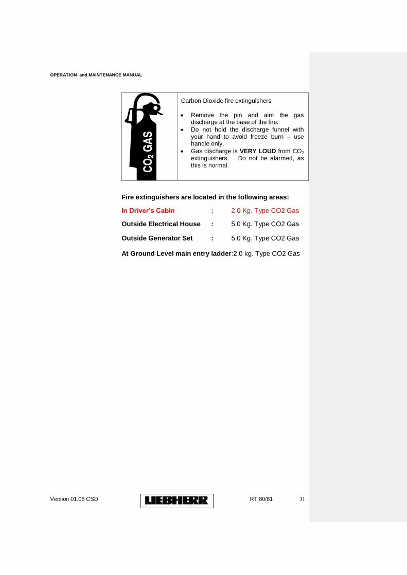
Carbon Dioxide fire extinguishers
Remove the pin and aim the gas discharge at the base of the fire.
Do not hold the discharge funnel with your hand to avoid freeze burn – use handle only.
Gas discharge is VERY LOUD from CO2 extinguishers. Do not be alarmed, as this is normal.
Fire extinguishers are located in the following areas: In Driver‟s Cabin : 2.0 Kg. Type CO2 Gas Outside Electrical House : 5.0 Kg. Type CO2 Gas Outside Generator Set : 5.0 Kg. Type CO2 Gas
At Ground Level main entry ladder:2.0 kg. Type CO2 Gas
OPERATION and MAINTENANCE MANUAL
Version 01.06 CSD RT 80/81 32
C. OPERATING INSTRUCTIONS AND DRIVER'S MANUAL
CRANE TYPE: RTG 6/5/4/WS(E)
WORK No: RT 80/81
DRAWING No: RT 1096

OPERATION and MAINTENANCE MANUAL
Version 01.06 CSD RT 80/81 33
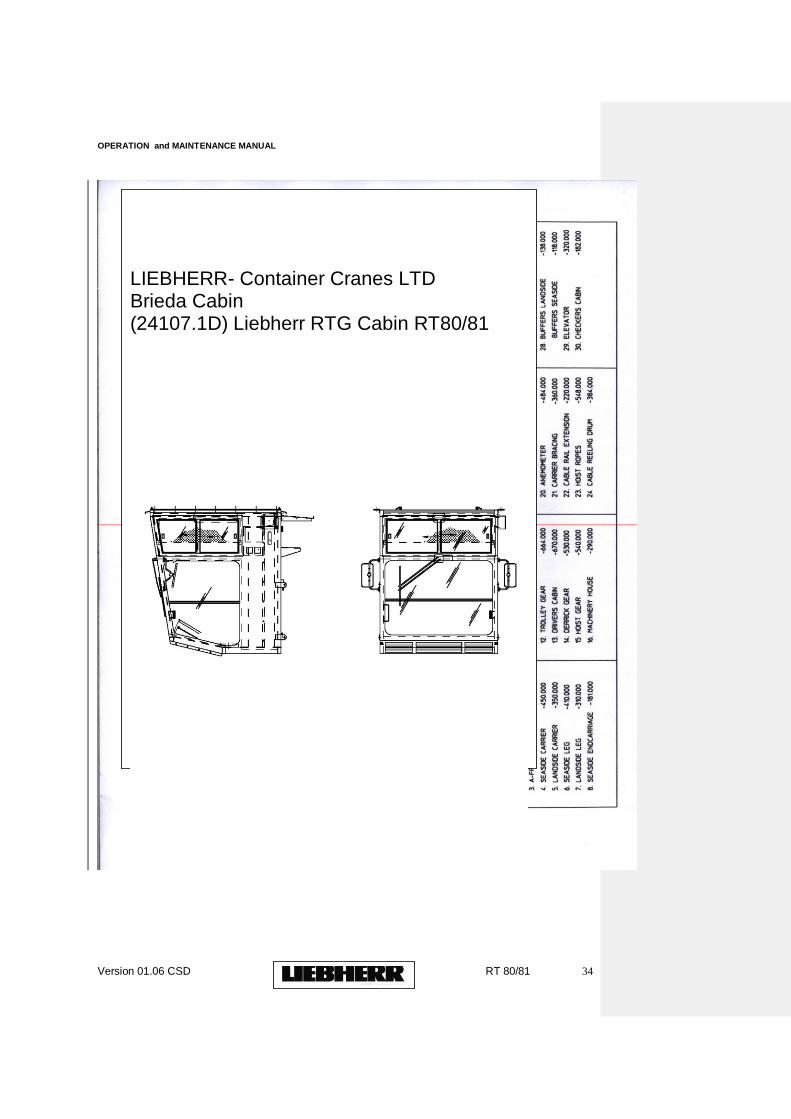
1.
CABIN
a) Drawing
OPERATION and MAINTENANCE MANUAL
Version 01.06 CSD RT 80/81 34
LIEBHERR- Container Cranes LTD Brieda Cabin (24107.1D) Liebherr RTG Cabin RT80/81
OPERATION and MAINTENANCE MANUAL
Version 01.06 CSD RT 80/81 35
OPERATION and MAINTENANCE MANUAL
Version 01.06 CSD RT 80/81 36
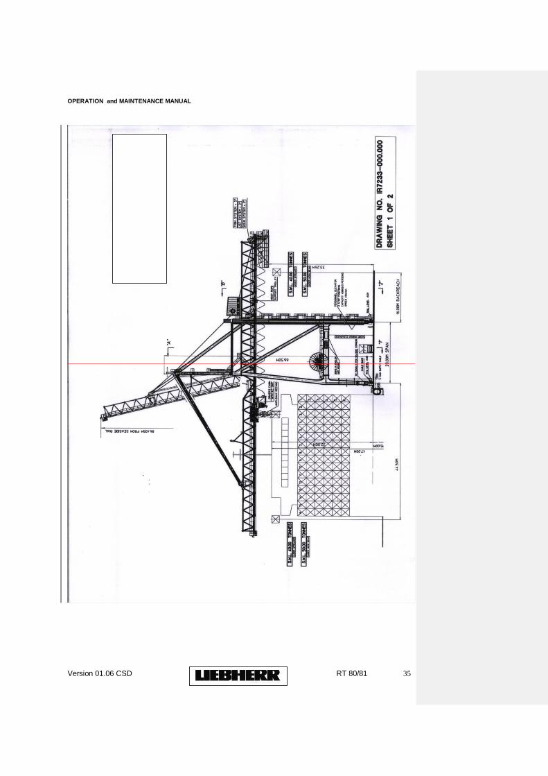
2. SUMMARY SPECIFICATION
CRANE TYPE P146L-SUPER CRANE WORK NOS. IR
1557 / IR 1558 DRAWING NO.: IR 7233-000.000
1. DESIGN The crane structurally
complies with F.E.M. 1.001 -1987 10.01, 3rd Edition. It is classified as follows:
CONTAINERS
HOOKBEAM
Class of Utilisation
U7
U5
State of Loading
Q3
Q2
Group Classif
A7
A5
OPERATION and MAINTENANCE MANUAL
Version 01.06 CSD RT 80/81 37
ication
The crane is designed
for handling:
I.S.O. containers of 20ft., 30ft.,
35ft., 40ft., 45ft. and 48ft. lengths weighing up to 40 Tonnes - all with appropriate lifting equipment. It is also designed to handle 2 x 20ft. empty containers in twin lift mode using the appropriate lifting equipment.
Cargo weighing up to 50 Tonnes
excluding the self-weight of a cargo beam (hookbeam). The cargo beam is attached to the underside of the headblock in a similar manner to the spreader.
The crane mechanically
complies with F.E.M. 1.001 1987, 10.01 3rd Edition. Each main motion is classified as follows:-
Group Classification Hoist Unit :
T7-L2-M7 Cross Travel Unit : T7-L2-M7 Long Travel Unit :
T4-L2-M4 Derrick Unit :
T3-L2-M3
2. SAFE WORKING LOAD
The S.W.L. of the crane is
40 Tonnes under Liebherr and Bromma telescopic spreaders over the full trolley travel path and 50 Tonnes under the hook beam over the full trolley travel path.
The spreader beam and
head block (Pulley Frame) collectively known as the lifting equipment have a total weight of 13.00 Tonnes. The head block is connected to the spreader or cargo beam using four manually operated pins.
Biçimlendirilmiş: Madde İşaretleri veNumaralandırma
Biçimlendirilmiş: Madde İşaretleri veNumaralandırma

OPERATION and MAINTENANCE MANUAL
Version 01.06 CSD RT 80/81 38
3. MAX. PERMISSIBLE CONTAINER ECCENTRICITY
The max. permissable
eccentricitiy for containers weighting up to 35.50 tonnes is:
1.22 m. in longitudinal
direction and 0.20 m. in lateral direction.
4. SPAN : 20.00
m.
5. OUTREACH ON WATERSIDE : 44.50 m.
(From Waterside Rail)
6. OUTREACH ON LANDSIDE : 16.00 m.
(From Landside Rail)
7. SPREADER HEIGHT ABOVE RAIL : 32.00 m.
(Seaside)
Total Spreader Hoisting
: 47.00 m. Lowest point of Spreader
below Rail : 15.00 m.
8. MAXIMUM OVERALL TROLLEY WIDTH : 6.990 m.
9. PORTAL STRUCTURE
9.1 Wheel Gauge (a)
Landside Rail : 18.53 m. (b)
Seaside Rail : 18.53 m. 9.2 Clearance Between
Portal Legs : 17.00 m. 9.3 Overall length Buffer to
Buffer : 29.10 m. (buffers compressed)
OPERATION and MAINTENANCE MANUAL
Version 01.06 CSD RT 80/81 39
9.4 Clearance under Portal Structure : 14.00 m.
10. DISTANCE WATERSIDE RAIL TO QUAY EDGE
: 3.80 m. (including fender)
11. RAIL LEVEL DIFFERENCE : 0.010 mm.
(Landside rail is at a higher level)
12. HOIST UNIT
2 x 300 kW DC Motors
with field weakening and Liebherr Digivert Speed Control. Load/speed range :
50 m./min. - 55.00 Tonnes **
60 m./min. - 53.00 Tonnes *
125m./min. - Empty Spreader
The Hoist speeds are continuously variable and load-dependent up to the max. speeds quoted above.

OPERATION and MAINTENANCE MANUAL
Version 01.06 CSD RT 80/81 40
12. HOIST UNIT (contd.)
* These loads include
the lifting equipment ** Heavy Lift Application NOTE(a): An Emergency Hoist
Drive System consisting of an A.C. motor and gear reduction unit is provided for emergency hoist operation
NOTE (b): Emergency braking is
provided on each hoist drum in addition to the normal braking system.
13. TROLLEY UNIT
4 x 35 kW D.C. Motors
with Digivert Thyristor Speed Control. (Self Powered Trolley). Speed
: 180 m./min. NOTE:- A hand driven trolley
travel system is provided for emergency purposes.
14. LONG TRAVEL UNIT
8 x 25 kW D.C. motors
with Digivert Thyristor Speed Control. Speed
: 45 m./min.
15. DERRICK UNIT
1 x 95 kW DC Motor with
Digivert Thyristor Speed Control. Derricking Time
: 5 minutes NOTE:- Derricking Emergency
Drive : 15 kW A.C. Motor, time approx. 30 Mins.
16. POWER SUPPLY
OPERATION and MAINTENANCE MANUAL
Version 01.06 CSD RT 80/81 41
11.0 kV, 50 Hz, 3 Phase + Earth, 3 wire plus earthed neutral system with 450 m. cable for approx. 750 m. crane travel.
Power Rating
: 1000 KVA
17. TRIM SYSTEM (±5º)
15 kW AC squirrel cage
motor (also used for List and Skew). Time to trim spreader by
5º : 16.0 seconds approx.
18. LIST SYSTEM (±3º)
15 kW AC squirrel cage
motor (also used for Trim and Skew). Time to List spreader by
3º : 8.0 seconds approx. (average)

OPERATION and MAINTENANCE MANUAL
Version 01.06 CSD RT 80/81 42
19. SKEW SYSTEM (±3º)
15 kW AC motor (also
used for Trim and List) Time to skew by 3º
: 8.0 seconds approx. (average)
20. NUMBER OF CRANE
WHEELS AND LOADINGS Seaside Rail
: 8 wheels/corner
38,34 tonnes / Wheel (In-Service) Wheel Distance
: 7 x 1300 mm. Landside Rail
: 8 wheels/corner
35.17 Tonnes / Wheel (In-Service) Wheel Distance
: 7 x 1300 mm. NOTE:- Seaside Rail is 10 mm.
lower than landside rail. Both rails are A100 Din 536.
21. DESIGN FEATURES 21.1 The crane is provided with
a lattice structure for boom and beam and uses clamped down A65 trolley rails on resilient pads. Special quality replaceable sections are used at the boom / beam hinge.
21.2 All main motions are
controlled using Thyristor Control Technology. 21.3 A computer based Fault
Condition Monitoring / Memory and Crane Management System is incorporated.
21.4 The crane is provided with
a High Tension 11.0 kV, 3 phase + earth, 3 wire + earthed neutral system, high Voltage supply with cable drum for 450 m. cable.
21.5 Load and spreader
Height Indicators are provided. 21.6 An Anemometer is fitted
and has its readout in the driver‟s cabin and electrical house.

OPERATION and MAINTENANCE MANUAL
Version 01.06 CSD RT 80/81 43
21.7 Hour meters for recording the operation time of the various drive units are installed in the main electrical switchgear.
21.8 A two-level Cable
Inspection Platform for the festoon cable system is provided. The system incorporates a cabin cleaning platform.
21.9 A head block with four pin
connection to the spreaders and heavy lift hook beam is provided. The pulley frame incorporates a geared anti-sway system. Supply to the spreader is via a cable basket on the head block.
21.10 A multi-point Telephone System
is installed. 21.11 Long Travel Control from
Derrick Control Cabin and from a ground station. 21.12 A 4.0 Tonne Service Crane is
provided in the machinery house. 21.13 All travel motions of the crane are
protected by pre-limit and final limit switches. 21.14 The crane is provided with
automatic storm pins and automatic ramp type rail clamps.
OPERATION and MAINTENANCE MANUAL
Version 01.06 CSD RT 80/81 44
21. DESIGN FEATURES (contd.)
21.15 The derrick system (two ropes)
for operating the boom incorporates a double brake arrangement with an Alni Overspeed device. Secondary brake acts directly on the drum. An emergency derrick drive system is also provided.
21.16 The crane is provided with a
LIEBHERR, 400 Kg, 4 person, 42 m./min 2 stop rope operated personnel lift enclosed within a lift shaft.
21.17 The hoist gear is provided with
two primary brakes, an emergency hoist system and emergency braking on each hoist drum.
21.18 The crane is designed for
operation with empty spreader when the boom is in the raised position.
21.19 A spacious driver‟s
cabin with double glazed tinted safety glazing is provided. An air conditioning unit and mirrors are provided.
21.20 The crane is provided with
a compartmented machinery house for mechanical equipment and switchgear with a separate entrance to each section. Both sections have insulated cladding. The switchgear section is air-conditioned. The house includes a 4.0 Tonne service crane and a re-reeving winch. An air-compressor, welding machine and bench drill are also provided.
21.21 A trim system ±5º, a list
system ±3º and a skew system ±3º is provided and also incorporates anti-snag and hoist rope adjustment features.
21.22 In addition to the lift above
(21.16), a stairs system is provided from lower landing level of lift to main beam. A stairs system is provided to machinery / electrical house and to derrick control cabin.
21.23 A hoist rope re-reeving
device is provided. 21.24 Long Travel buffers are provided
with long travel limit switches. 21.25 An emergency stand-by power
connection point is provided. 21.26 An extensive tool list is provided. 21.27 One hoist rope support trolley is
provided on the landside of the main trolley.
OPERATION and MAINTENANCE MANUAL
Version 01.06 CSD RT 80/81 45
21.28 Power factor correction equipment is provided.
21.29 The crane is provided with a
checkers cabin under the landside end carriage. 21.30 Emergency drives are provided
for hoist and derrick systems and a hand operated emergency system is provided on the trolley.
22. LIFTING EQUIPMENT The crane is provided with a head block
(pulley frame) which is designed for attaching the new lifting equipment. It has a 4-pin connection to the lifting equipment
The total Lifting
Equipment provided for the two cranes is as follows: (a) Head Block (Pulley
frame) with each crane. (b) 3 x Off Liebherr
Telescopic Spreaders (c) 1 x Off Bromma
Twin-Lift Telescopic Spreader (d) 1 x Adaptor Frame -
to be used when any of the spreaders under (b) and (c) above are connected to the previous Liebherr and other container cranes owned by the port.

OPERATION and MAINTENANCE MANUAL
Version 01.06 CSD RT 80/81 46
NOTE: One Liebherr spreader and the Bromma spreader are considered as „spare parts‟.
23. OPERATIONAL LIMITATIONS
Boom Down Full operation with full load
over full length of boom and beam. Boom Up Full operation with empty
spreader over full length of boom and beam. Simultaneous motions The hoist / lowering, trolley
travel and long travel can be carried out simultaneously. NOTE: Boom shall always be in
fully raised position in “out-of-service” conditions. The In-Service wind speed
is 72 km/hr. (45 m.p.h.)
24. COLOUR
Crane Structure
Ultra Marine Blue - RAL 5002
Boom Tip
Traffic Red - RAL 3020
25. COMMISSIONING The Crane Commissioning
Dates are: Work No. IR 1557
2000

OPERATION and MAINTENANCE MANUAL
Version 01.06 CSD RT 80/81 47
Work No. IR 1558 2000
OPERATION and MAINTENANCE MANUAL
Version 01.06 CSD RT 80/81 48
2. LAYOUT OF CONTROLS
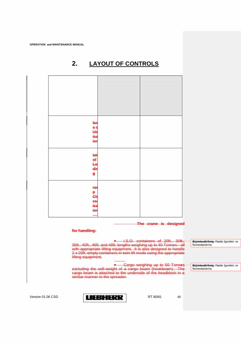
CONTAINERS
HOOKBEAM
Class of Utilisation
U7
U5
State of Loading
Q3
Q2
Group Classification
A7
A5
The crane is designed
for handling:
I.S.O. containers of 20ft., 30ft.,
35ft., 40ft., 45ft. and 48ft. lengths weighing up to 40 Tonnes - all with appropriate lifting equipment. It is also designed to handle 2 x 20ft. empty containers in twin lift mode using the appropriate lifting equipment.
Cargo weighing up to 50 Tonnes
excluding the self-weight of a cargo beam (hookbeam). The cargo beam is attached to the underside of the headblock in a similar manner to the spreader.
Biçimlendirilmiş: Madde İşaretleri veNumaralandırma
Biçimlendirilmiş: Madde İşaretleri veNumaralandırma
OPERATION and MAINTENANCE MANUAL
Version 01.06 CSD RT 80/81 49
The crane mechanically complies with F.E.M. 1.001 1987, 10.01 3rd Edition. Each main motion is classified as follows:-
Group Classification Hoist Unit :
T7-L2-M7 Cross Travel Unit : T7-L2-M7 Long Travel Unit :
T4-L2-M4 Derrick Unit :
T3-L2-M3
2. SAFE WORKING LOAD
The S.W.L. of the crane is
40 Tonnes under Liebherr and Bromma telescopic spreaders over the full trolley travel path and 50 Tonnes under the hook beam over the full trolley travel path.
The spreader beam and
head block (Pulley Frame) collectively known as the lifting equipment have a total weight of 13.00 Tonnes. The head block is connected to the spreader or cargo beam using four manually operated pins.
OPERATION and MAINTENANCE MANUAL
Version 01.06 CSD RT 80/81 50
3. MAX. PERMISSIBLE CONTAINER ECCENTRICITY
The max. permissable
eccentricitiy for containers weighting up to 35.50 tonnes is:
1.22 m. in longitudinal
direction and 0.20 m. in lateral direction.
4. SPAN : 20.00
m.
5. OUTREACH ON WATERSIDE : 44.50 m.
(From Waterside Rail)
6. OUTREACH ON LANDSIDE : 16.00 m.
(From Landside Rail)
7. SPREADER HEIGHT ABOVE RAIL : 32.00 m.
(Seaside)
Total Spreader Hoisting
: 47.00 m. Lowest point of Spreader
below Rail : 15.00 m.
8. MAXIMUM OVERALL TROLLEY WIDTH : 6.990 m.
9. PORTAL STRUCTURE
9.1 Wheel Gauge (a)
Landside Rail : 18.53 m. (b)
Seaside Rail : 18.53 m. 9.2 Clearance Between
Portal Legs : 17.00 m. 9.3 Overall length Buffer to
Buffer : 29.10 m. (buffers compressed)

OPERATION and MAINTENANCE MANUAL
Version 01.06 CSD RT 80/81 51
9.4 Clearance under Portal Structure : 14.00 m.
10. DISTANCE WATERSIDE RAIL TO QUAY EDGE
: 3.80 m. (including fender)
11. RAIL LEVEL DIFFERENCE : 0.010 mm.
(Landside rail is at a higher level)
12. HOIST UNIT
2 x 300 kW DC Motors
with field weakening and Liebherr Digivert Speed Control. Load/speed range :
50 m./min. - 55.00 Tonnes **
60 m./min. - 53.00 Tonnes *
125m./min. - Empty Spreader
The Hoist speeds are continuously variable and load-dependent up to the max. speeds quoted above.
OPERATION and MAINTENANCE MANUAL
Version 01.06 CSD RT 80/81 52
12. HOIST UNIT (contd.)
* These loads include
the lifting equipment ** Heavy Lift Application NOTE(a): An Emergency Hoist
Drive System consisting of an A.C. motor and gear reduction unit is provided for emergency hoist operation
NOTE (b): Emergency braking is
provided on each hoist drum in addition to the normal braking system.
13. TROLLEY UNIT
4 x 35 kW D.C. Motors
with Digivert Thyristor Speed Control. (Self Powered Trolley). Speed
: 180 m./min. NOTE:- A hand driven trolley
travel system is provided for emergency purposes.
14. LONG TRAVEL UNIT
8 x 25 kW D.C. motors
with Digivert Thyristor Speed Control. Speed
: 45 m./min.
15. DERRICK UNIT
1 x 95 kW DC Motor with
Digivert Thyristor Speed Control. Derricking Time
: 5 minutes NOTE:- Derricking Emergency
Drive : 15 kW A.C. Motor, time approx. 30 Mins.
16. POWER SUPPLY

OPERATION and MAINTENANCE MANUAL
Version 01.06 CSD RT 80/81 53
11.0 kV, 50 Hz, 3 Phase + Earth, 3 wire plus earthed neutral system with 450 m. cable for approx. 750 m. crane travel.
Power Rating
: 1000 KVA
17. TRIM SYSTEM (±5º)
15 kW AC squirrel cage
motor (also used for List and Skew). Time to trim spreader by
5º : 16.0 seconds approx.
18. LIST SYSTEM (±3º)
15 kW AC squirrel cage
motor (also used for Trim and Skew). Time to List spreader by
3º : 8.0 seconds approx. (average)
OPERATION and MAINTENANCE MANUAL
Version 01.06 CSD RT 80/81 54
19. SKEW SYSTEM (±3º)
15 kW AC motor (also
used for Trim and List) Time to skew by 3º
: 8.0 seconds approx. (average)
20. NUMBER OF CRANE
WHEELS AND LOADINGS Seaside Rail
: 8 wheels/corner
38,34 tonnes / Wheel (In-Service) Wheel Distance
: 7 x 1300 mm. Landside Rail
: 8 wheels/corner
35.17 Tonnes / Wheel (In-Service) Wheel Distance
: 7 x 1300 mm. NOTE:- Seaside Rail is 10 mm.
lower than landside rail. Both rails are A100 Din 536.
21. DESIGN FEATURES 21.1 The crane is provided with
a lattice structure for boom and beam and uses clamped down A65 trolley rails on resilient pads. Special quality replaceable sections are used at the boom / beam hinge.
21.2 All main motions are
controlled using Thyristor Control Technology. 21.3 A computer based Fault
Condition Monitoring / Memory and Crane Management System is incorporated.
21.4 The crane is provided with
a High Tension 11.0 kV, 3 phase + earth, 3 wire + earthed neutral system, high Voltage supply with cable drum for 450 m. cable.
21.5 Load and spreader
Height Indicators are provided. 21.6 An Anemometer is fitted
and has its readout in the driver‟s cabin and electrical house.
OPERATION and MAINTENANCE MANUAL
Version 01.06 CSD RT 80/81 55
21.7 Hour meters for recording the operation time of the various drive units are installed in the main electrical switchgear.
21.8 A two-level Cable
Inspection Platform for the festoon cable system is provided. The system incorporates a cabin cleaning platform.
21.9 A head block with four pin
connection to the spreaders and heavy lift hook beam is provided. The pulley frame incorporates a geared anti-sway system. Supply to the spreader is via a cable basket on the head block.
21.10 A multi-point Telephone System
is installed. 21.11 Long Travel Control from
Derrick Control Cabin and from a ground station. 21.12 A 4.0 Tonne Service Crane is
provided in the machinery house. 21.13 All travel motions of the crane are
protected by pre-limit and final limit switches. 21.14 The crane is provided with
automatic storm pins and automatic ramp type rail clamps.
OPERATION and MAINTENANCE MANUAL
Version 01.06 CSD RT 80/81 56
21. DESIGN FEATURES (contd.)
21.15 The derrick system (two ropes)
for operating the boom incorporates a double brake arrangement with an Alni Overspeed device. Secondary brake acts directly on the drum. An emergency derrick drive system is also provided.
21.16 The crane is provided with a
LIEBHERR, 400 Kg, 4 person, 42 m./min 2 stop rope operated personnel lift enclosed within a lift shaft.
21.17 The hoist gear is provided with
two primary brakes, an emergency hoist system and emergency braking on each hoist drum.
21.18 The crane is designed for
operation with empty spreader when the boom is in the raised position.
21.19 A spacious driver‟s
cabin with double glazed tinted safety glazing is provided. An air conditioning unit and mirrors are provided.
21.20 The crane is provided with
a compartmented machinery house for mechanical equipment and switchgear with a separate entrance to each section. Both sections have insulated cladding. The switchgear section is air-conditioned. The house includes a 4.0 Tonne service crane and a re-reeving winch. An air-compressor, welding machine and bench drill are also provided.
21.21 A trim system ±5º, a list
system ±3º and a skew system ±3º is provided and also incorporates anti-snag and hoist rope adjustment features.
21.22 In addition to the lift above
(21.16), a stairs system is provided from lower landing level of lift to main beam. A stairs system is provided to machinery / electrical house and to derrick control cabin.
21.23 A hoist rope re-reeving
device is provided. 21.24 Long Travel buffers are provided
with long travel limit switches. 21.25 An emergency stand-by power
connection point is provided. 21.26 An extensive tool list is provided. 21.27 One hoist rope support trolley is
provided on the landside of the main trolley.
OPERATION and MAINTENANCE MANUAL
Version 01.06 CSD RT 80/81 57
21.28 Power factor correction equipment is provided.
21.29 The crane is provided with a
checkers cabin under the landside end carriage. 21.30 Emergency drives are provided
for hoist and derrick systems and a hand operated emergency system is provided on the trolley.
22. LIFTING EQUIPMENT The crane is provided with a head block
(pulley frame) which is designed for attaching the new lifting equipment. It has a 4-pin connection to the lifting equipment
The total Lifting
Equipment provided for the two cranes is as follows: (a) Head Block (Pulley
frame) with each crane. (b) 3 x Off Liebherr
Telescopic Spreaders (c) 1 x Off Bromma
Twin-Lift Telescopic Spreader (d) 1 x Adaptor Frame -
to be used when any of the spreaders under (b) and (c) above are connected to the previous Liebherr and other container cranes owned by the port.
OPERATION and MAINTENANCE MANUAL
Version 01.06 CSD RT 80/81 58
NOTE: One Liebherr spreader and the Bromma spreader are considered as „spare parts‟.
23. OPERATIONAL LIMITATIONS
Boom Down Full operation with full load
over full length of boom and beam. Boom Up Full operation with empty
spreader over full length of boom and beam. Simultaneous motions The hoist / lowering, trolley
travel and long travel can be carried out simultaneously. NOTE: Boom shall always be in
fully raised position in “out-of-service” conditions. The In-Service wind speed
is 72 km/hr. (45 m.p.h.)
24. COLOUR
Crane Structure
Ultra Marine Blue - RAL 5002
Boom Tip
Traffic Red - RAL 3020
25. COMMISSIONING The Crane Commissioning
Dates are: Work No. IR 1557
2000
OPERATION and MAINTENANCE MANUAL
Version 01.06 CSD RT 80/81 59
Work No. IR 1558 2000
2.1 DRIVER'S CABIN EQUIPMENT
The following equipment is incorporated in the driver's cabin:
2.1.1 Driver's Control Console; incorporates the control joysticks, push-buttons, selector switches and status lights for crane and spreader operation.
Audible and visual warning devices, electrical fault and overload warning zone also included.
2.1.2 EMS Display Panel: incorporating digital readout display of load, height, trim, skew angle position, and status indication for spreader, i.e. twistlocks open, twistlocks closed, and deposit points.
2.1.3
Air conditioning unit
2.1.4 Cabin Light.
2.1.5 Crane Lighting control: incorporating push-buttons for:
Crane Floodlighting - Trolley Access Lighting
2.1.6 Emergency Light.
2.1.7 Socket Outlet – 230 V.
2.1.8 Windscreen Wiper / Washer.
2.1.9 Telephone Handset 2.1.10 Signal Horn 2.1.11 Fire Extinguisher 2.1.12 Public Address System
2.1.13. Heater

OPERATION and MAINTENANCE MANUAL
Version 01.06 CSD RT 80/81 60
NOTE: All joystick controls, push-buttons, selector switches, indication lamps, audio devices, and visual displays are highlighted by legend plates identifying their corresponding functions.

OPERATION and MAINTENANCE MANUAL
Version 01.06 CSD RT 80/81 61
PLEASE FIND ON FOLLOWING PAGES
ILLUSTRATIONS, DESCRIPTIONS AND
DISPLAYS COVERING CONTROL
LAYOUT

OPERATION and MAINTENANCE MANUAL
Version 01.06 CSD RT 80/81 62
OPERATION and MAINTENANCE MANUAL
Version 01.06 CSD RT 80/81 63
LAYOUT OF CONTROLS
EMS-2 LCC BUTTON FUNCTIONS
The EMS has 14 buttons, arranged in two rows of 7 buttons underneath the LCD display.
The upper seven buttons are denoted B1 to B7, from left to right, and are used to select crane driver’s
displays 1 to 6 and machine data display 1 (diagnosis display).
B2 button Selects crane driver’s display 2 (See “DISPLAY 2”)
B3 button Selects crane driver’s display 3 (See “DISPLAY 3”)
B4 button Selects crane driver’s display 4 (See “DISPLAY 4”)
B5 button Selects crane driver’s display 5 (See “DISPLAY 5”)
B6 button Selects crane driver’s display 6 (See “DISPLAY 6”)
B7 button Selects machine data display 1
The lower seven buttons are used to operate the EMS menu structures.
button Moves the cursor to the left, or changes the display in the highlighted display section.
button Moves the cursor to the right, or changes the display in the highlighted display section.
button Moves the cursor upwards, or increases a value.
button Moves the cursor downwards, or reduces a value.
Clear button Changes a setting to an initial or standard value.
Enter button Activates selected menu items, or confirms value inputs.
Key button Selects the main menu display.
OPERATION and MAINTENANCE MANUAL
Version 01.06 CSD RT 80/81 64
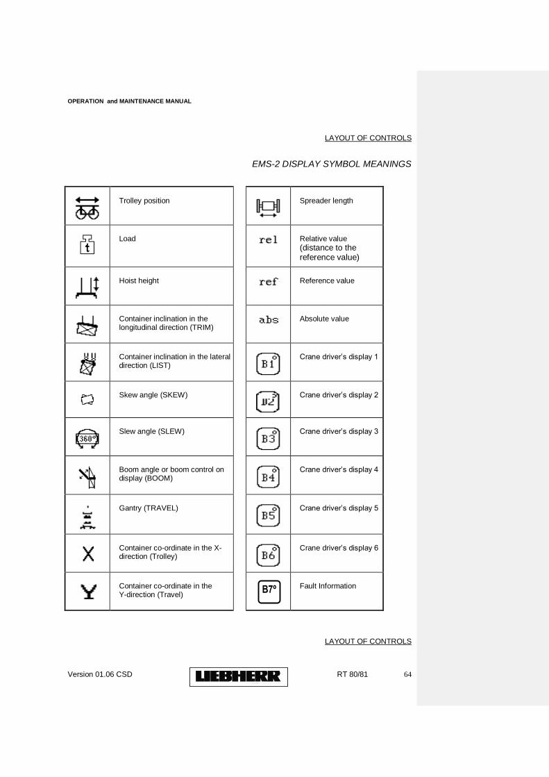
LAYOUT OF CONTROLS
EMS-2 DISPLAY SYMBOL MEANINGS
Trolley position
Spreader length
Load
Relative value
(distance to the reference value)
Hoist height
Reference value
Container inclination in the longitudinal direction (TRIM)
Absolute value
Container inclination in the lateral direction (LIST)
Crane driver‟s display 1
Skew angle (SKEW)
Crane driver‟s display 2
Slew angle (SLEW)
Crane driver‟s display 3
Boom angle or boom control on display (BOOM)
Crane driver‟s display 4
Gantry (TRAVEL)
Crane driver‟s display 5
Container co-ordinate in the X-direction (Trolley)
Crane driver‟s display 6
Container co-ordinate in the Y-direction (Travel)
Fault Information
LAYOUT OF CONTROLS
B7º
OPERATION and MAINTENANCE MANUAL
Version 01.06 CSD RT 80/81 65
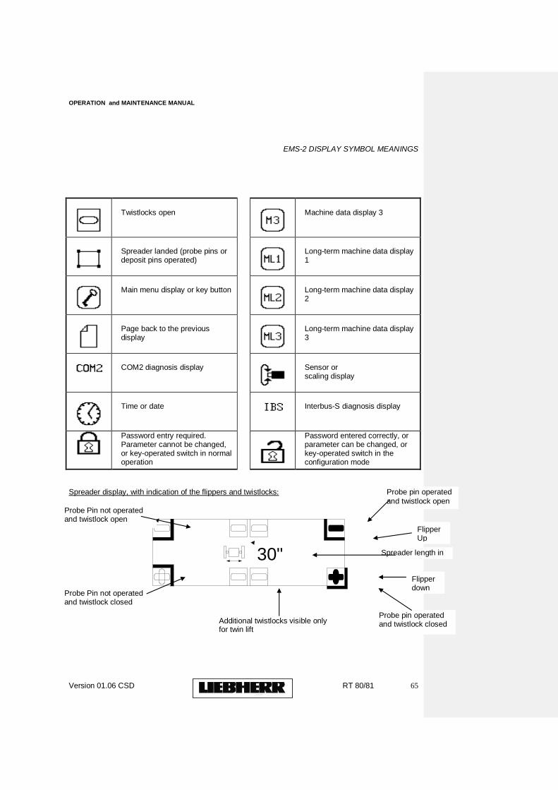
EMS-2 DISPLAY SYMBOL MEANINGS
Twistlocks open
Machine data display 3
Spreader landed (probe pins or deposit pins operated)
Long-term machine data display 1
Main menu display or key button
Long-term machine data display 2
Page back to the previous display
Long-term machine data display 3
COM2 diagnosis display
Sensor or scaling display
Time or date
Interbus-S diagnosis display
Password entry required. Parameter cannot be changed, or key-operated switch in normal operation
Password entered correctly, or parameter can be changed, or key-operated switch in the configuration mode
Spreader display, with indication of the flippers and twistlocks:
30"
Probe Pin not operated and twistlock open
Spreader length in feet
Probe pin operated
and twistlock open
Probe pin operated and twistlock closed Additional twistlocks visible only
for twin lift
Probe Pin not operated and twistlock closed
Flipper down
Flipper Up
OPERATION and MAINTENANCE MANUAL
Version 01.06 CSD RT 80/81 66
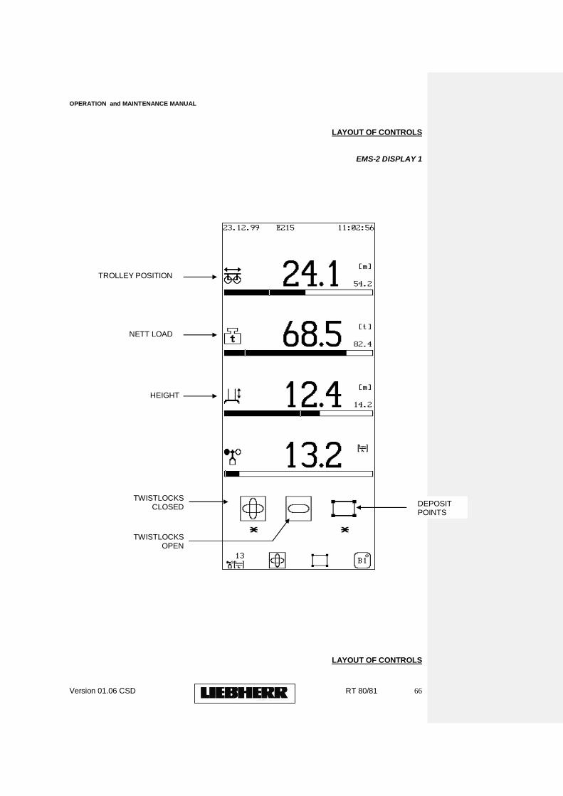
LAYOUT OF CONTROLS
EMS-2 DISPLAY 1
LAYOUT OF CONTROLS
TWISTLOCKS CLOSED
TWISTLOCKS OPEN
NETT LOAD
HEIGHT
TROLLEY POSITION
DEPOSIT POINTS
OPERATION and MAINTENANCE MANUAL
Version 01.06 CSD RT 80/81 67
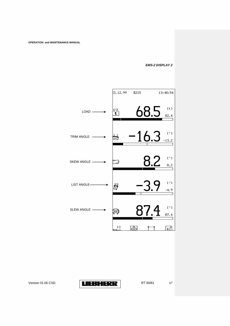
EMS-2 DISPLAY 2
LOAD
TRIM ANGLE
SKEW ANGLE
SLEW ANGLE
LIST ANGLE
OPERATION and MAINTENANCE MANUAL
Version 01.06 CSD RT 80/81 68
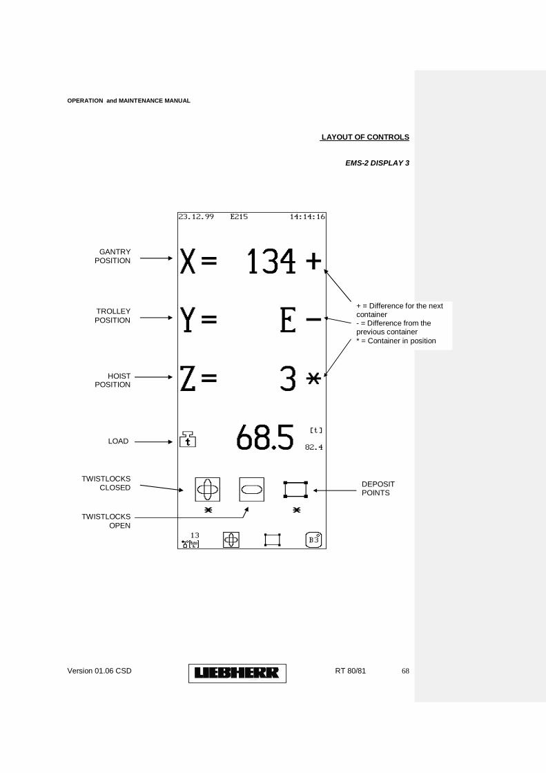
LAYOUT OF CONTROLS
EMS-2 DISPLAY 3
TWISTLOCKS
OPEN
LOAD
DEPOSIT POINTS
TWISTLOCKS CLOSED
GANTRY POSITION
HOIST POSITION
TROLLEY
POSITION
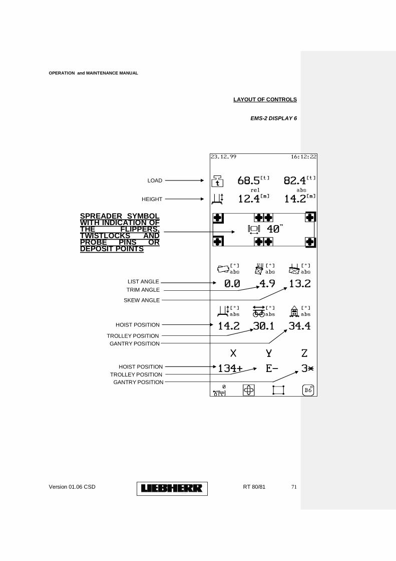
+ = Difference for the next container - = Difference from the previous container
* = Container in position
OPERATION and MAINTENANCE MANUAL
Version 01.06 CSD RT 80/81 69
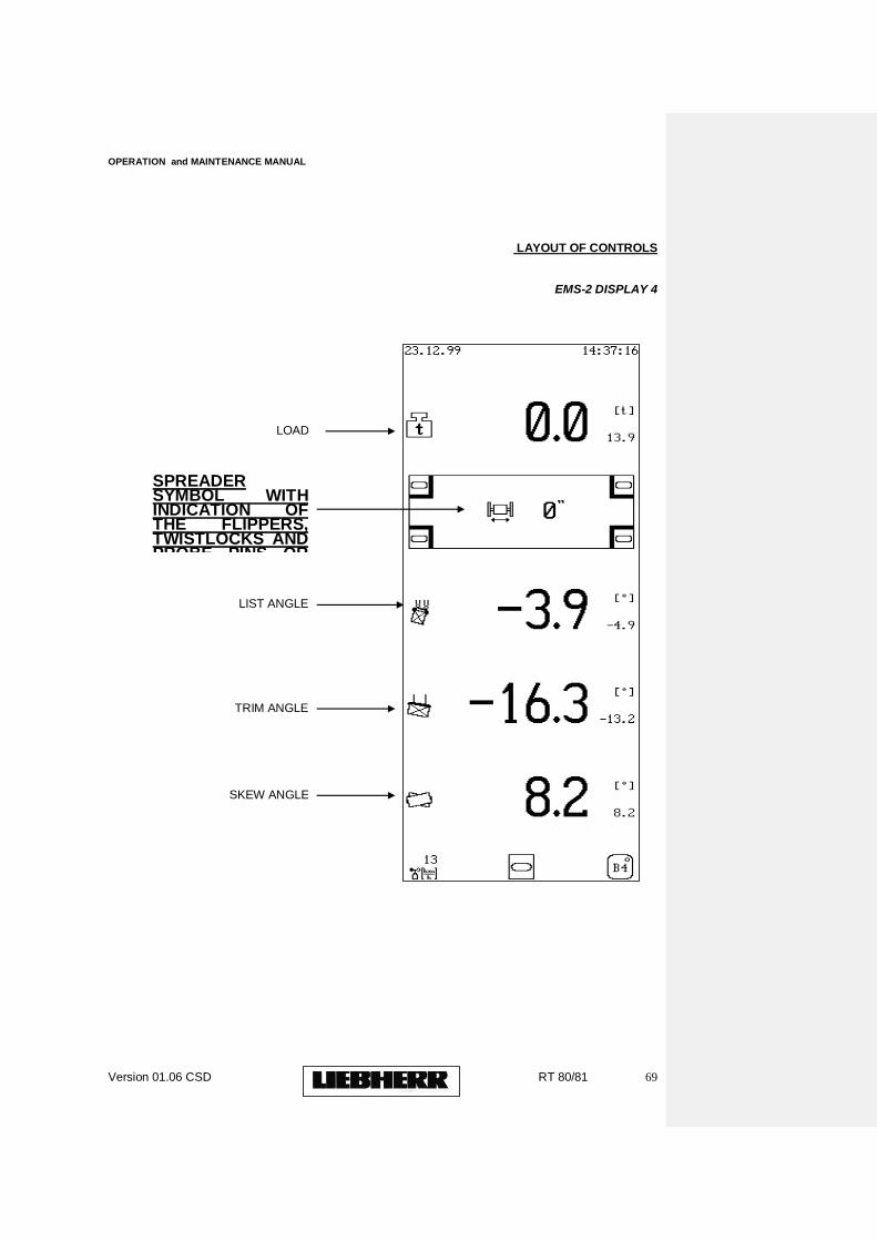
LAYOUT OF CONTROLS
EMS-2 DISPLAY 4
LOAD
LIST ANGLE
TRIM ANGLE
SKEW ANGLE
SPREADER SYMBOL WITH INDICATION OF THE FLIPPERS, TWISTLOCKS AND PROBE PINS OR DEPOSIT POINTS
OPERATION and MAINTENANCE MANUAL
Version 01.06 CSD RT 80/81 70
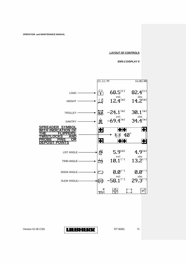
LAYOUT OF CONTROLS
EMS-2 DISPLAY 5
LOAD
HEIGHT
TROLLEY
GANTRY
SPREADER SYMBOL WITH INDICATION OF THE FLIPPERS, TWISTLOCKS AND PROBE PINS OR DEPOSIT POINTS
LIST ANGLE
TRIM ANGLE
SKEW ANGLE
SLEW ANGLE
OPERATION and MAINTENANCE MANUAL
Version 01.06 CSD RT 80/81 71
LAYOUT OF CONTROLS
EMS-2 DISPLAY 6
LOAD
HEIGHT
GANTRY POSITION
TROLLEY POSITION
HOIST POSITION
SKEW ANGLE
TRIM ANGLE
LIST ANGLE
SPREADER SYMBOL WITH INDICATION OF THE FLIPPERS, TWISTLOCKS AND PROBE PINS OR DEPOSIT POINTS
HOIST POSITION
TROLLEY POSITION
GANTRY POSITION
OPERATION and MAINTENANCE MANUAL
Version 01.06 CSD RT 80/81 72
3. STARTING THE CRANE
To put the RTG into service for any period of time, two steps must be taken which are:
Start Main Diesel.
Start RTG Drives.
Before starting the RTG, please ensure that the following items have been checked:
(a) Ensure that all fuel levels are okay.
(b) Ensure that chock blocks are away from wheels and properly stowed.
(c) Ensure all diesel e-stops are in the RESET / ON position.
(d) Ensure that main diesel is in auto-run mode. NOTE: Main Diesel to be in this mode all times except when
maintenance work is being carried out on Diesel / Generator Set
3.1 To Start Main Diesel Proceed to RTG Main Entry E-House Entry. Diesel Control Panel located on ladder. Press green pushbutton ( DIESEL ON) If Diesel refuses to start, suspend all operations until fault is rectified OR
Proceed to Driver‟s Cabin. Press illuminated Push Button Diesel ON on Left Hand Control
Console. The push-buttons light will flash for a few seconds until the main diesel is up and running and then it will illuminate constant. If this light remains flashing, this means there is a problem with starting the main diesel, therefore further operations should be suspended, the fault determined and rectified.
Prior to switching RTG drives ON, ensure:
(a) All joysticks are in Neutral. (b) Electrical fault lamp / buzzer are OFF. (c) Anchor pin is released - status light should be OFF (Status light illuminated indicates anchor pin is anchored in place). (d) All emergency stops are in the RESET/ ON position.
OPERATION and MAINTENANCE MANUAL
Version 01.06 CSD RT 80/81 73
(e) All gates on portal / cab entry are closed. (f) Ensure that the status light respective to the wheel position is illuminated. At the driver‟s control console, switch on as follows:
3.2 Starting RTG drives ON 3.2.1 Press Crane ON Push-button on left hand control console. The built-in-Status Lamp will flash for a few seconds then will illuminate constant. NOTE: Flashing light indicates that not all drives have been energised. If this happens, further operation should be suspended, the cause determined and rectified. No light indicates that all drives have not been energised. A self-test of approx. 2 seconds duration is initiated, where upon all status lights on driver‟s control console panel are switched ON to verify that same are operative. Check that the following are operative: CRANE ON Status Light - Switched ON. SPREADER ON, Status Light, - Switched ON. spreader beam switched ON indicating twistlocks OPEN. 3.3. Check that the following are inoperative: OVERLOAD Warning Status Lamp - Switched OFF. OVERLOAD Status Lamp - Switched OFF. ELECTRICAL FAULT Status Lamp- Switched OFF. ELECTRICAL FAULT Audio Alarm- Switched OFF. DIESEL FAULT Status Lamp - Switched OFF. LOW FUEL LEVEL Status Lamp - Switched OFF. ANTI-COLLISION Status Lamp - Switched OFF. Should any of the above be operative, crane operation should immediately be ceased, the reason determined and the necessary action taken. 3.4. A push-button for ANTI-COLLISION OVERRIDE is provided to allow bypass of travel Anti-Collision Limit Switches to allow movement of crane away from object.
OPERATION and MAINTENANCE MANUAL
Version 01.06 CSD RT 80/81 74
3.5 Spreader is switched ON automatically when CRANE ON button is pressed. Green twistlocks Open Lamp on Spreader Beam will indicate this. 3.5.1 Spreader can be switched OFF at any time by pressing the spreader OFF button. Right Hand Console. 3.5.2 Spreader can be started by pushing CRANE ON button again. 3.5.3 A two-position selector switch is provided for spreader length selection as follows: 1 - 20ft. Spreader. 2 - 40ft. Spreader 3.6 Trim / Skew / Steering operate automatic ON with joysticks and automatic time delayed OFF after usage.
3.7 Access way lighting and main floodlighting are controlled by two switches on Left Hand Console. 3.8 Windscreen washer and wiper controlled by two switches on Right hand Console. 3.9 A three-position selector switch is provided for FAN and HEATER selection as follows: 1 - Fan and Heater OFF. 2 - Fan ON and Heater OFF. 3. - Fan and Heater ON. 3.10 Cabin Air Condition Unit is automatic start. Remote control for individual comfort settings on right-hand sidewall of cabin. 3.11 Ashtray located to front of Right Hand console.
3.12 Public Address System with floor mounted footswitch and left-hand console mounted microphone fitted in cabin. Amplifier for P.A. System mounted on outside of Right Hand Console.
3.13 Telephone System To communicate with ground level, electrical house and numerous other points throughout crane located on side of actual left console.
OPERATION and MAINTENANCE MANUAL
Version 01.06 CSD RT 80/81 75
4.
TAKING THE RTG OUT-OF-SERVICE NOTE CRANE MUST TO BE TAKEN “OUT OF SERVICE” IF THE WIND SPEED EXCEEDS 72 KM/H. WHEN PUTTING THE CRANE OUT OF SERVICE FOR ANY PERIOD, HOWEVER SHORT, THE FOLLOWING PROCEDURE MUST BE STRICTLY ADHERED TO. ONLY THEN CAN IT BE PROPERLY ENSURED THAT THE CRANE IS SAFELY PARKED AND IS CAPABLE OF WITHSTANDING THE FORCES IMPOSED BY STRONG WINDS. 4.1 Remove load from lifting equipment. 4.2 Park crane in parking area. 4.3 Park trolley in parking area at entry platform. 4.4 Hoist spreader to max. height.
4.5 Wheels should not be turned in out-of-service
position. Wheel chocks used. 4.6 Switch off as follows at the driver‟s control console : (a) Ensure joysticks for all drives are in NEUTRAL POSITION. (b) Press CRANE OFF pushbutton. The various status lights for the crane operation are switched off. 4.7 Turn off main diesel by pushing main DIESEL OFF button on the Left-hand console. NOTE : Main Diesel on lamp will now flash repeatedly. This indicates the main diesel is in the SWITCH OFF mode. There is a time delay of approx. 1 minute before main diesel actually shuts down.
4.8 Manually lower Storm Anchor pin on Trolley. 4. 9 Go to ground level. 4. 10 Install chock blocks under wheels. 4. 11 Plug in auxiliary power supply. This is required for lighting, heating / cooling and anti-condensation heating throughout the crane.
OPERATION and MAINTENANCE MANUAL
Version 01.06 CSD RT 80/81 76
4. 11 The following equipment on the crane is fitted with Anti-Condensation Heating: (a) Electrical Switchgear Panels (b) Electronic Regulator Panels (c) Main A.C. Drive Motors (d) Hydraulic unit motors (e) Diesel Terminal / Electronic Panel WARNING THE ANTI-CONDENSATION HEATING EQUIPMENT MUST REMAIN ON AT ALL TIMES WHEN THE CRANE IS OUT OF SERVICE. IT IS ABSOLUTELY ESSENTIAL THAT THE POWER SUPPLY TO THE ANTI-CONDENSATION HEATING IS NOT INTERRUPTED TO PREVENT CONDENSATION BUILD-UP WHICH MAY DAMAGE ELECTRICAL / ELECTRONIC EQUIPMENT AND COMPONENTS. The Anti-Condensation heating system should be monitored regularly for correct operation. THE MANUFACTURER WILL NOT ACCEPT ANY DAMAGE CLAIM RESULTING FROM FAILURE TO COMPLY WITH THE ABOVE INSTRUCTIONS. WARNING IF THE CRANE IS TO REMAIN “OUT OF SERVICE” FOR A PERIOD LONGER THAN THREE WEEKS, SPECIAL STORAGE PRECAUTIONS SHOULD BE TAKEN TO AVOID DAMAGE TO CRANE COMPONENTS. IF SUCH CIRCUMSTANCES ARISE, CONSULT THE MANUFACTURER FOR ADVICE. FAILURE TO COMPLY WITH THESE PRECAUTIONS WILL FORFEIT GUARANTEE CONDITIONS.
OPERATION and MAINTENANCE MANUAL
Version 01.06 CSD RT 80/81 77
5. OPERATING THE RTG 5.1 HOIST UNIT OPERATION 5.1.1 OPERATION NOTE: The master joystick for Hoist / Travel/ Twistlocks and Trolley are spring return to Zero position types. The hoist system is controlled by means of the joystick on the right-hand control console. Forward movement of the joystick is for lowering, backward movement for hoisting. Continuously variable speeds from creep speed to full speed may be achieved in both directions. To commence hoisting, push the joystick in the desired direction. The further the joystick is moved the faster the hoist motion will run. “Positioning Mode” on right hand joy stick ( left hand side) is for creep speed lowering of the hoist drive unit.
5.1.2 OVERLOAD PROTECTION SYSTEM (For further details, see Part 2) The Overload Protection System provides for the safe operation of the crane/hoisting equipment. Overload gives a visual and audible warning when the lifted load exceeds the safe working load of the crane/hoisting equipment. Further hoisting of the load is prevented and the load may only be lowered. 5.1.3 LIMIT SWITCHES Limit Switches are incorporated in the hoist control system, which provide for the proper functioning of the hoist “up” and “down” functions. The following limit switches are provided: Hoist Up / Down Rotary limit switch coupled to hoist rope drums, incorporating the following functions: Hoist Prelimitation Up Slows the hoist up motion to creep speed close to the maximum hoist up position. Hoist Up Stops the hoist up motion at the maximum hoist up position.
OPERATION and MAINTENANCE MANUAL
Version 01.06 CSD RT 80/81 78
Hoist Prelimitation Down Slows the hoist down motion to creep speed close to the ground when lowering. Hoist Down This stops the hoist down motion at the maximum hoist down position. Hoist Overspeed This stops the hoist motion, when the hoist drum exceeds 10% faster than rated speed Hoist Up Emergency Stop A proximity limit switch is mounted on the trolley, which provides for an emergency stop hoist „up‟ position. In the event of this limit switch being activated, maintenance personnel should be notified to reset the electrical control, which prevents further hoist equipment motion, the hoist should then be carefully lowered, and the cause of the failure established. 5.1.4 HOIST HEIGHT POSITION A potentiometer coupled to the rotary limit switch at the hoist rope drum provides for visual indication of hoisting height on the EMS display panel in the driver‟s cabin. NOTE: IN THE EVENT OF EQUIPMENT MALFUNCTION, CRANE OPERATION SHOULD IMMEDIATELY BE STOPPED, THE EXACT SEQUENCE OF FAILURE NOTED AND MAINTENANCE PERSONNEL NOTIFIED. THE REASON FOR MALFUNCTION OR FAILURE SHOULD BE DETERMINED AND CORRECTED IMMEDIATELY.
5.2 TROLLEY DRIVE SYSTEM OPERATION
5.2.1 OPERATION NOTE: The master joysticks for Hoist / Travel / Twistlock and Trolley are spring return to zero position types. The trolley system is controlled by means of the joystick on the left-hand control console. Forward movement of the joystick is for trolley forward motion, and reverse movement for trolley reverse motion. Continuously variable speed from creep speeds to full speed may be achieved in both directions. To commence trolleying, push the joystick in the desired direction. The further the joystick is moved, the faster the trolley motion will run.
OPERATION and MAINTENANCE MANUAL
Version 01.06 CSD RT 80/81 79
Limit switches are incorporated in the trolley control system which provide for the proper functioning of the trolley “forward” and “reverse” motions. 5.2.2 LIMIT SWITCHES The following limit switches are provided: Forward Main Beam Stop Stops the trolley forward motion at the end of the Main Beam. (Controlled by Proximity Switch) Reverse Mainbeam Stop Stops the trolley reverse motion at the end of the main beam. (Controlled by Proximity Switch) Forward/ Reverse main Beam Premilitation 25% Slows the trolley reverse motion to 25 % of full speed close to the end of the Main Beam. (Controlled by Encoder) Reverse / Forward Main Beam Prelimitation 10% Slows the trolley forward and reverse motion to 10% of full speed close to the end of the Main Beam. (Controlled by Encoder) 5.2.3. Flipper Movement N/A 5.3 CRANE TRAVEL DRIVE SYSTEM OPERATION 5.3.1 OPERATION NOTE: The master joysticks for Hoist / Travel / Twistlocks and Trolley are spring return to zero position types. The travel system is controlled by means of a joystick on the right-hand control console. Right movement of the joystick is for travel right motion; left movement is for travel left motion. Continuously variable speeds from creep speed to full speed may be achieved in both directions. To commence travelling, push joystick in the desired direction. The further the joystick is moved, the faster the travel motion will run.
OPERATION and MAINTENANCE MANUAL
Version 01.06 CSD RT 80/81 80
5.3.2 ANTI-COLLISION Lateral Anti-Collision limit switches are fitted on endcarriage 1+2. In the event of activating one of these (crane E-stop situation), press the Anti-Collision override pushbutton on the right-hand console, which allows “back-out” of crane travel operation by reverse movement of joystick. 5.3.3 ALIGNMENT AND STEERING An RTG differs from rail mounted cranes. To maintain straight and true travel along the marked out tracks, it is necessary to do the following: Travel right or left using joystick on right-hand console. If and when crane goes out of alignment, i.e. pulling away from track, it is possible to align it simultaneously as crane travels, the main joystick on Left Hand console can be moved to right or left to correct the alignment. This is done by increasing the speed of the far side of crane and at same time decreasing the speed of near side or vice-versa.
5.3.4. CRANE TURNING / TRAVERSING
The necessary command devices to enable crane turning and/or traversing are provided on the right-hand control console.
The following devices are provided: 1. Wheels “ 0 “ pos. – pushbutton / lamp 2. Wheels spin pos. – pushbutton / lamp 3. Wheels 90 degrees pos. – pushbutton / lamp. To enable traversing, press pushbutton WHEELS 90 DEGR. POS., when status light has switched ON and wheels are in 90 degrees pos., it is possible to move crane from current row to desired row by moving the joystick on the right-hand control console. Bu pressing pushbutton WHEELS “0” pos. normal travel operation can again be resumed. To enable circle turning, press pushbutton Wheel Spin Pos. Status Light for same switched ON. Wheels at four corners are aligned to enable crane to turn about its centre point.
OPERATION and MAINTENANCE MANUAL
Version 01.06 CSD RT 80/81 81
5.4 SPREADER BEAM OPERATION 5.4.1 OPERATION The spreader control is switched on via push-button CRANE ON on the driver‟s control console. A push-button for SPREADER OFF is provided for switching OFF if required. The twistlocks are controlled via pushbuttons fitted to the topside of the right-hand joystick controller. The following buttons are provided - Blue button twistlocks lock. - Yellow button Twistlocks Unlock. Status lights fitted to spreader beam give indication of twistlocks OPEN and/ or closed status, the following lamps are provided: - Green lamps Twistlocks OPEN - Red lamp Twistlocks CLOSED The telescope expand / retract functions are controlled via selector switch fitted to left side of console. The following positions are provided: - 20 ft position - 40 ft position
5.5. TRIM / SKEW OPERATION 5.5.1 FUNCTION The Trim System provides for the lowering/ raising of the ends of the spreader beam / container with respect to the horizontal by ±2.5. The Skew System provides for rotation of the spreader beam / container around its vertical axis by an angle of ±5% from its normal, parallel to the long travel rail position.
5.5.2 OPERATION The Trim / Skew system is switched on via the push-button CRANE ON on the left-hand control console. For a time only, thereafter by moving either joystick or by reset to zero. Trim and Skew are controlled via pushbuttons fitted to topside of left-hand joystick controller. To select trim or skew, just press the appropriate button until selected operation is performed. Press Green button : “Trim Left”
OPERATION and MAINTENANCE MANUAL
Version 01.06 CSD RT 80/81 82
Press Yellow button : “Trim Right” Press Red button : “Skew Left” Press Blue button : “Skew Right” Trim and Skew motions are achieved by controlled shortening / lengthening of the hoist ropes. Visual indication of Trim / Skew angles are provided on the EMS-Display Panel. The left pushbutton on the front side of the left-hand joystick controller provides for Auto-Zeroing of the Trim / List system. NOTE: Auto Reset to “Zero” of trim/skew takes place when spreader with load is raised to the one container over three height. Auto reset to “Zero” of skew takes place when trolley reverses into parking area and when the trolley enters the forward pre-10% limit zone. It is possible again to adjust skew when trolley is stopped in this area. NOTE: IN THE EVENT OF EQUIPMENT MALFUNCTION, CRANE OPERATION SHOULD IMMEDIATELY BE STOPPED, THE EXACT SEQUENCE OF FAILURE NOTED AND MAINTENANCE PERSONNEL NOTIFIED. THE REASON FOR MALFUNCTION OR FAILURE SHOULD BE DETERMINED AND CORRECTED IMMEDIATELY.
OPERATION and MAINTENANCE MANUAL
Version 01.06 CSD RT 80/81 83
6. CHANGING THE SPREADER The Bromma type YSX40E spreader is specially designed for the direct rope attachment to the RTG without the use of a headblock. To change the spreader the following steps must be taken: 1. Lower spreader to ground level. Place a timber board under each of the twist locks. Pay out the ropes (by lowering hoist) until the spreader link pieces are in a horizontal position. 2. Switch off spreader and disconnect spreader cable socket from plug on spreader. Disconnect the cable basket mountings and move the cable basket out of the way. 3. Disconnect all eight hoist ropes by removing the pins of the rope spelter sockets. 4. Attach another spreader by following above points in reverse sequence.
SEE DRAWING NEXT PAGE
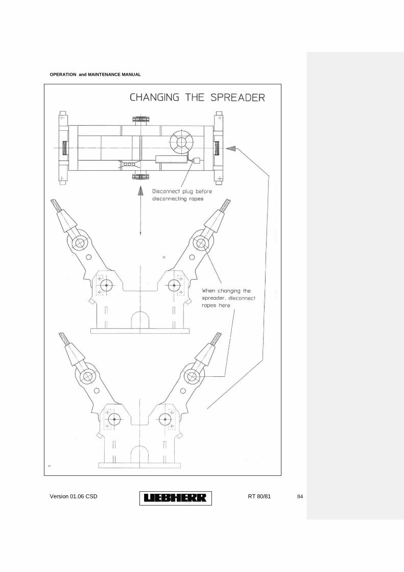
OPERATION and MAINTENANCE MANUAL
Version 01.06 CSD RT 80/81 84
OPERATION and MAINTENANCE MANUAL
Version 01.06 CSD RT 80/81 85
7.
MAINTENANCE AND INSPECTION GENERAL The LIEBHERR RTG must be kept in good and safe structural, mechanical, hydraulical and electrical condition at all times. The maintenance, part replacement and lubrication instructions in the different sections of this manual must be strictly adhered to. All safety systems and devices must be operational at all times and kept in good condition. If crane insurance, local safety standards and regulations do not insist on regular inspection, Liebherr recommends the following minimum check and test procedures for the RTG: Six months after handover, a thorough examination of the complete RTG should be carried out by a competent person. Thereafter the thorough examination should be repeated at least every twelve months. The examination should be carried out with the RTG in operation and at rest. It is understood that when any fault, faulty part or damage is discovered within the check intervals, a repair or replacement is arranged for immediately and not delayed until the next examination is due. After any substantial modification or repair, an RTG overload test is required, as carried out for initial RTG commissioning. The RTG structure, mechanical, hydraulic and electrical equipment must be in safe and good condition. After the overload test, a thorough examination should take place as described above. At the completion of the test and examination, all safety devices should be restored and checked to ensure that they function correctly. It is imperative that complete records are kept of all above examinations and tests. Any abnormalities found and recorded must be passed on to Liebherr Container Cranes Ltd. for comment. NOTE: Liebherr should be informed before any substantial modifications or major repair work is carried out. Carrying out modifications to the RTG without approval from Liebherr may result in the loss of the Liebherr guarantee.
OPERATION and MAINTENANCE MANUAL
Version 01.06 CSD RT 80/81 86
7.1 SUMMARY OF MAINTENANCE AND LUBRICATION Introduction The importance of regular routine preventative maintenance cannot be over stressed. The benefits arising from a properly organised and scheduled maintenance programme are: a. Maintenance in itself ensures that the RTG and its components are maintained in good operating condition, thus ensuring minimum crane operation downtime. b. Machine and component inspection which form a large and crucial part of a good maintenance programme, in many instances highlight potential problems which though not of immediate consequence, could prove to be problematic in the long term. c. Equipment functionality checks and tests are extremely important particular with respect to safety features and devices. The maintenance programme detailed in the following pages is provided as a general purpose guideline only. It neither claims to be totally comprehensive nor fully accurate in all details, with respect to any given RTG. It does however, provide a solid foundation on which a comprehensive maintenance schedule for a particular RTG may be built and / or customised. It should also be noted that in particular the maintenance time intervals indicated are approximate. In reality, these intervals should depend on RTG usage and therefore may need to be adjusted accordingly. See also various sections in the Manual for more specific details. See also page detailing oil/grease type and quantities. If Lubricant Laboratory Tests are required they can be provided by LIEBHERR at a fee per item prior to lubricant changes if required.
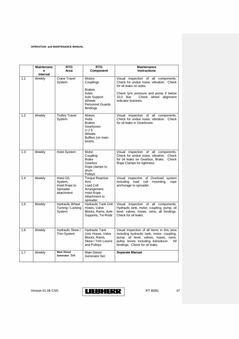
OPERATION and MAINTENANCE MANUAL
Version 01.06 CSD RT 80/81 87
Maintenance
Interval
RTG Area
RTG Component
Maintenance Instructions
1.1 Weekly Crane Travel System
Motors Couplings Brakes Axles Axle Support Wheels Personnel Guards Bindings
Visual inspection of all components. Check for undue noise, vibration. Check for oil leaks on axles. Check tyre pressure and pump if below 10.0 Bar. Check wheel alignment indicator brackets.
1.2 Weekly Trolley Travel System
Motors Hubs Brakes Gearboxes U J S Wheels Buffers (on main beam)
Visual inspection of all components. Check for undue noise, vibration. Check for oil leaks in Gearboxes.
1.3 Weekly Hoist System Motor Coupling Brake Gearbox Rope clamps to drum. Pulleys
Visual inspection of all components. Check for undue noise, vibration. Check for oil leaks on Gearbox, Brake. Check Rope Clamps for tightness.
1.4 Weekly Hoist O/L System, Hoist Rope to Spreader attachment
Torque Reaction Arm. Load Cell Arrangement. Hoist Rope Attachment to spreader.
Visual inspection of Overload system including load cell mounting, rope anchorage to spreader.
1.5 Weekly Hydraulic Wheel Turning / Locking System
Hydraulic Tank Unit Hoses, Valve Blocks, Rams, Axle Supports, Tie Rods
Visual inspection of all components, Hydraulic tank, motor, coupling, pump, oil level, valves, hoses, rams, all bindings. Check for oil leaks.
1.6 Weekly Hydraulic Skew / Trim System
Hydraulic Tank Unit, Hoses, Valve Blocks, Rams, Skew / Trim Levers and Pulleys
Visual inspection of all items in this area including hydraulic tank, motor, coupling, pump, oil level, valves, hoses, rams, pulley levers including transducer. All bindings. Check for oil leaks.
1.7 Weekly Main Diesel
Generator Set Main Diesel Generator Set
Separate Manual
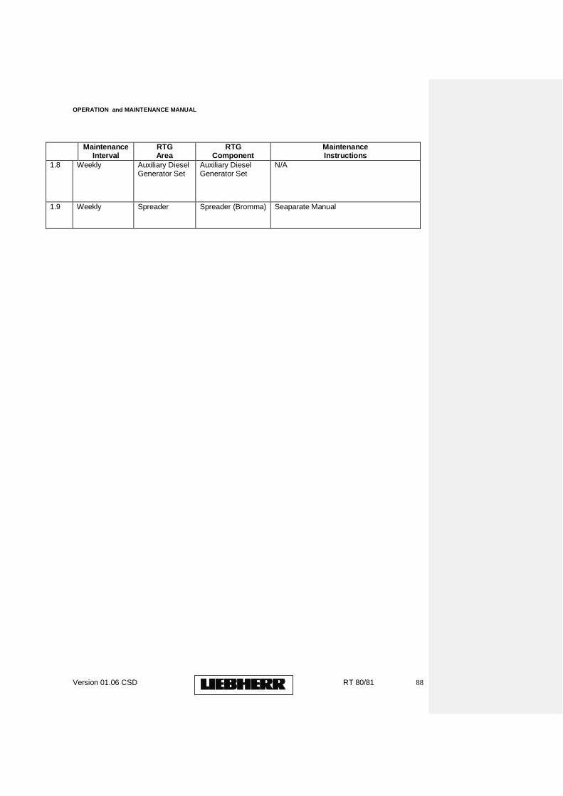
OPERATION and MAINTENANCE MANUAL
Version 01.06 CSD RT 80/81 88
Maintenance Interval
RTG Area
RTG Component
Maintenance Instructions
1.8 Weekly Auxiliary Diesel Generator Set
Auxiliary Diesel Generator Set
N/A
1.9 Weekly Spreader
Spreader (Bromma)
Seaparate Manual
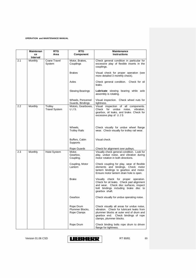
OPERATION and MAINTENANCE MANUAL
Version 01.06 CSD RT 80/81 89
Maintenance
Interval
RTG Area
RTG Component
Maintenance Instructions
2.1 Monthly Crane Travel System
Motor, Brakes, Couplings Brakes Axles Slewing Bearings Wheels, Personnel Guards, Bindings
Check general condition in particular for excessive play of flexible inserts in the couplings. Visual check for proper operation (see more detailed 3 monthly check). Check general condition. Check for oil leaks. Lubricate slewing bearing while axle assembly is rotating. Visual inspection. Check wheel nuts for tightness.
2.2 Monthly Trolley Travel System
Motors, Gearboxes, U J S. Wheels, Trolley Rails Buffers, Cabin Supports Rope Guards
Visual inspection of all components. Check for undue noise, vibration, gearbox, oil leaks, and brake. Check for excessive play of U J S Check visually for undue wheel flange wear. Check visually for trolley rail wear. Visual check. Check for alignment over pulleys.
2.3 Monthly Hoist System Motor, Gearbox, Coupling. Coupling, Motor Lantern Brake Gearbox Rope Drum Plummer Blocks, Rope Clamps Rope Drum
Visually check general condition. Look for play, undue noise, and vibration during motor rotation in both directions. Check coupling for play, wear of flexible elements and bindings. Check motor lantern bindings to gearbox and motor. Ensure motor lantern drain hole is open. Visually check for proper operation. Check for oil leaks. Check pad alignment and wear. Check disc surfaces, inspect bolt bindings including brake disc to gearbox shaft. Check visually for undue operating noise. Check visually all areas for undue noise, vibration. Check for lubricant leaks from plummer blocks at outer end of drum and gearbox end. Check bindings of rope clamps, plummer blocks. Check binding bolts rope drum to driven flange for tightness.
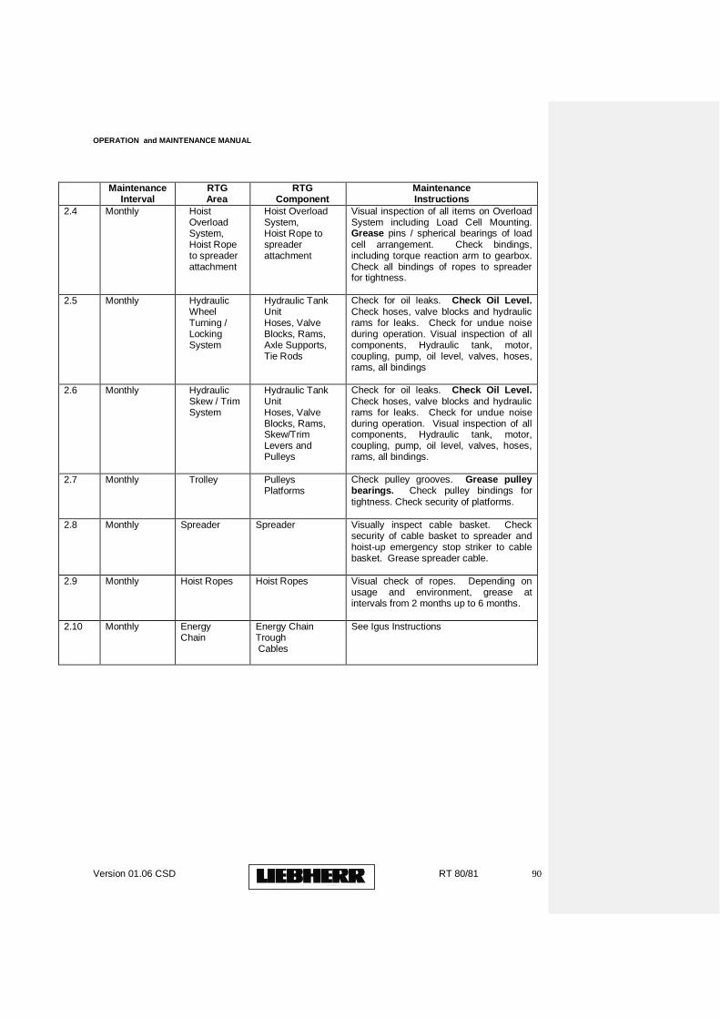
OPERATION and MAINTENANCE MANUAL
Version 01.06 CSD RT 80/81 90
Maintenance Interval
RTG Area
RTG Component
Maintenance Instructions
2.4 Monthly Hoist Overload System, Hoist Rope to spreader attachment
Hoist Overload System, Hoist Rope to spreader attachment
Visual inspection of all items on Overload System including Load Cell Mounting. Grease pins / spherical bearings of load cell arrangement. Check bindings, including torque reaction arm to gearbox. Check all bindings of ropes to spreader for tightness.
2.5 Monthly Hydraulic Wheel Turning / Locking System
Hydraulic Tank Unit Hoses, Valve Blocks, Rams, Axle Supports, Tie Rods
Check for oil leaks. Check Oil Level. Check hoses, valve blocks and hydraulic rams for leaks. Check for undue noise during operation. Visual inspection of all components, Hydraulic tank, motor, coupling, pump, oil level, valves, hoses, rams, all bindings
2.6 Monthly Hydraulic Skew / Trim System
Hydraulic Tank Unit Hoses, Valve Blocks, Rams, Skew/Trim Levers and Pulleys
Check for oil leaks. Check Oil Level. Check hoses, valve blocks and hydraulic rams for leaks. Check for undue noise during operation. Visual inspection of all components, Hydraulic tank, motor, coupling, pump, oil level, valves, hoses, rams, all bindings.
2.7 Monthly Trolley Pulleys Platforms
Check pulley grooves. Grease pulley bearings. Check pulley bindings for tightness. Check security of platforms.
2.8 Monthly Spreader Spreader
Visually inspect cable basket. Check security of cable basket to spreader and hoist-up emergency stop striker to cable basket. Grease spreader cable.
2.9 Monthly Hoist Ropes Hoist Ropes
Visual check of ropes. Depending on usage and environment, grease at intervals from 2 months up to 6 months.
2.10 Monthly Energy Chain
Energy Chain Trough Cables
See Igus Instructions
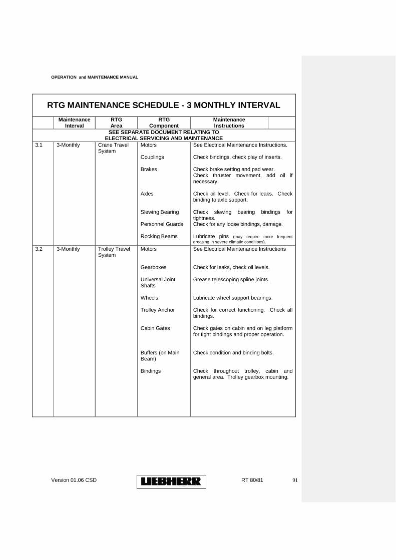
OPERATION and MAINTENANCE MANUAL
Version 01.06 CSD RT 80/81 91
RTG MAINTENANCE SCHEDULE - 3 MONTHLY INTERVAL
Maintenance Interval
RTG Area
RTG Component
Maintenance Instructions
SEE SEPARATE DOCUMENT RELATING TO ELECTRICAL SERVICING AND MAINTENANCE
3.1 3-Monthly Crane Travel System
Motors Couplings Brakes Axles Slewing Bearing Personnel Guards Rocking Beams
See Electrical Maintenance Instructions. Check bindings, check play of inserts. Check brake setting and pad wear. Check thruster movement, add oil if necessary. Check oil level. Check for leaks. Check binding to axle support. Check slewing bearing bindings for tightness. Check for any loose bindings, damage. Lubricate pins (may require more frequent
greasing in severe climatic conditions).
3.2 3-Monthly Trolley Travel System
Motors Gearboxes Universal Joint Shafts Wheels Trolley Anchor Cabin Gates Buffers (on Main Beam) Bindings
See Electrical Maintenance Instructions Check for leaks, check oil levels. Grease telescoping spline joints. Lubricate wheel support bearings. Check for correct functioning. Check all bindings. Check gates on cabin and on leg platform for tight bindings and proper operation. Check condition and binding bolts. Check throughout trolley, cabin and general area. Trolley gearbox mounting.
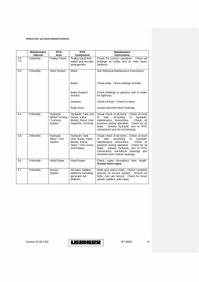
OPERATION and MAINTENANCE MANUAL
Version 01.06 CSD RT 80/81 92
Maintenance Interval
RTG Area
RTG Component
Maintenance Instructions
3.2 contd
3-Monthly Trolley Travel Trolley travel limit switch and encoder arrangement.
Check for correct operation. Check all bindings on trolley and on main beam (strikers)
3.3
3-Monthly Hoist System Motor Brake Brake Support bracket Gearbox Rope Drum
See Electrical Maintenance Instructions Check pads. Check settings of brake Check bindings to gearbox and to brake for tightness. Check oil level. Check for leaks. Grease plummer block bearings
3.4
3-Monthly Hydraulic Wheel Turning / Locking System
Hydraulic Tank Unit Hoses, Valve Blocks, Rams, Axle Supports, Tie Rods
Visual check of all items. Check oil level of tank according to hydraulic maintenance instructions. Check oil pressure during operation. Check for oil leaks. Grease hydraulic ram to RTG connections and tie rod bearings.
3.5
3-Monthly Hydraulic Skew / Trim System
Hydraulic Tank Unit, Hoses, Valve Blocks, Rams, Skew / Trim Levers and Pulleys
Visual check of all items. Check oil level of tank according to hydraulic maintenance instructions. Check oil pressure during operation. Check for oil leaks. Grease hydraulic ram to RTG connections, transducer bearings and skew/trim lever bottom bearings.
3.6
3-Monthly Hoist Ropes Hoist Ropes
Check ropes throughout their length. Grease hoist ropes.
3.7
3-Monthly Access System
All stairs, ladders, platforms including generator set platform.
Walk over entire crane. Check complete security of access system. Ensure all bolts, nuts are secure. Check for loose panels, ladders, stair steps.
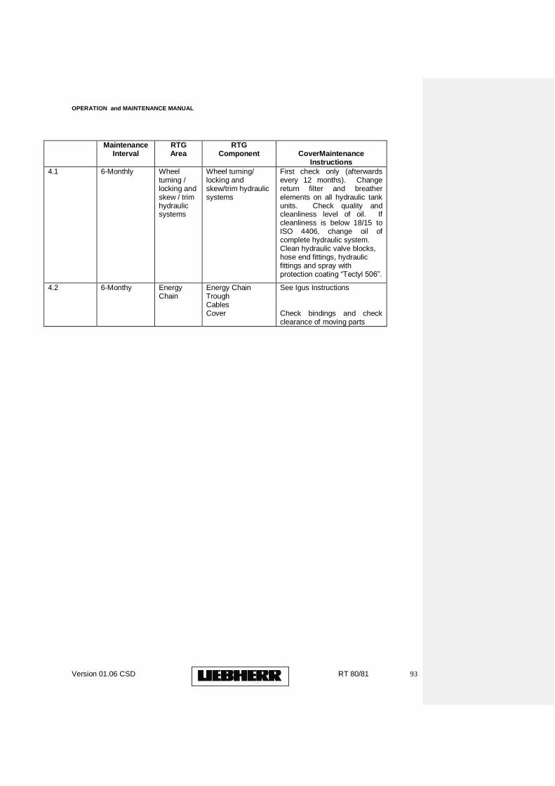
OPERATION and MAINTENANCE MANUAL
Version 01.06 CSD RT 80/81 93
Maintenance Interval
RTG Area
RTG Component
CoverMaintenance
Instructions
4.1 6-Monthly Wheel turning / locking and skew / trim hydraulic systems
Wheel turning/ locking and skew/trim hydraulic systems
First check only (afterwards every 12 months). Change return filter and breather elements on all hydraulic tank units. Check quality and cleanliness level of oil. If cleanliness is below 18/15 to ISO 4406, change oil of complete hydraulic system. Clean hydraulic valve blocks, hose end fittings, hydraulic fittings and spray with protection coating “Tectyl 506”.
4.2 6-Monthy Energy Chain
Energy Chain Trough Cables Cover
See Igus Instructions Check bindings and check clearance of moving parts
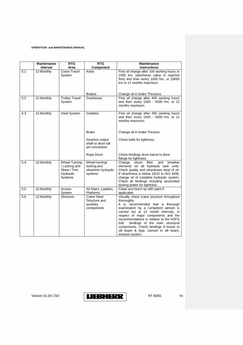
OPERATION and MAINTENANCE MANUAL
Version 01.06 CSD RT 80/81 94
Maintenance Interval
RTG Area
RTG Component
Maintenance Instructions
5.1
12-Monthly Crane Travel System
Axles Brakes
First oil change after 100 working hours or 1000 km. (whichever value is reached first) and then every 1000 hrs. or 10000 km or 12 months maximum. Change oil in brake Thrustors
5.2 12-Monthly Trolley Travel System
Gearboxes
First oil change after 400 working hours and then every 1500 - 5000 hrs. or 12 months maximum.
5.3 12-Monthly Hoist System Gearbox Brake Gearbox output shaft to drum tail pin connection Rope Drum
First oil change after 400 working hours and then every 1500 - 5000 hrs. or 12 months maximum. Change oil in brake Thrustor. Check bolts for tightness. Check bindings drum barrel to drive flange for tightness.
5.4 12-Monthly Wheel Turning / Locking and Skew / Trim Hydraulic Systems
Wheel turning/ locking and skew/trim hydraulic systems
Change return filter, and breather elements on all hydraulic tank units. Check quality and cleanliness level of oil. If cleanliness is below 18/15 to ISO 4406, change oil of complete hydraulic system. Check all bindings including associated locking plates for tightness.
5.5 12-Monthly Access System
All Stairs, Ladders, Platforms
Clean and touch up with paint if applicable.
5.6 12-Monthly Structure Crane Steel Structure and auxiliary components
Visually check crane structure throughout thoroughly. It is recommended that a thorough examination by a competent person is carried out at 12 month intervals, in respect of major components and the recommendations in relation to the HSFG bolt bindings of the main structural components. Check bindings E-house to sill beam & legs, Genset to sill beam, exhaust system.
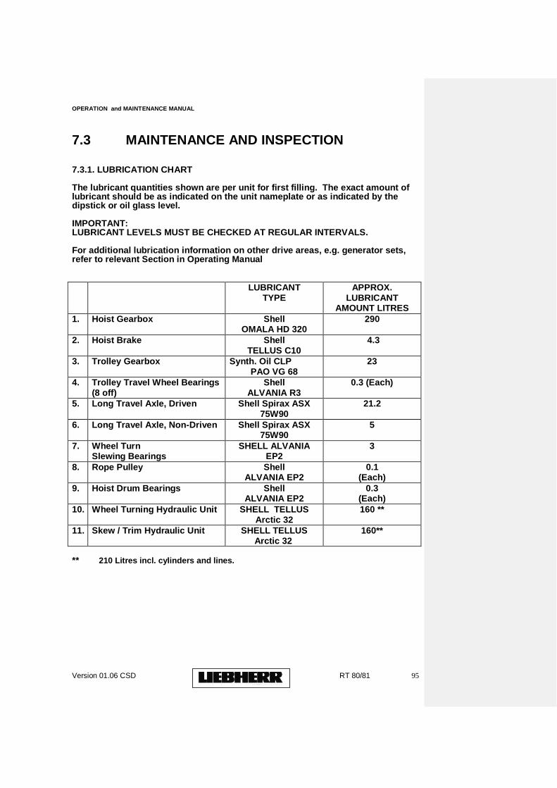
OPERATION and MAINTENANCE MANUAL
Version 01.06 CSD RT 80/81 95
7.3 MAINTENANCE AND INSPECTION
7.3.1. LUBRICATION CHART
The lubricant quantities shown are per unit for first filling. The exact amount of lubricant should be as indicated on the unit nameplate or as indicated by the dipstick or oil glass level.
IMPORTANT: LUBRICANT LEVELS MUST BE CHECKED AT REGULAR INTERVALS.
For additional lubrication information on other drive areas, e.g. generator sets, refer to relevant Section in Operating Manual
LUBRICANT
TYPE APPROX.
LUBRICANT AMOUNT LITRES
1. Hoist Gearbox Shell OMALA HD 320
290
2. Hoist Brake Shell TELLUS C10
4.3
3. Trolley Gearbox Synth. Oil CLP PAO VG 68
23
4. Trolley Travel Wheel Bearings (8 off)
Shell ALVANIA R3
0.3 (Each)
5. Long Travel Axle, Driven Shell Spirax ASX 75W90
21.2
6. Long Travel Axle, Non-Driven Shell Spirax ASX 75W90
5
7. Wheel Turn Slewing Bearings
SHELL ALVANIA EP2
3
8. Rope Pulley
Shell ALVANIA EP2
0.1 (Each)
9. Hoist Drum Bearings
Shell ALVANIA EP2
0.3 (Each)
10. Wheel Turning Hydraulic Unit SHELL TELLUS Arctic 32
160 **
11. Skew / Trim Hydraulic Unit SHELL TELLUS Arctic 32
160**
** 210 Litres incl. cylinders and lines.
OPERATION and MAINTENANCE MANUAL
Version 01.06 CSD RT 80/81 96
8. CRANE SIGNS A) PIECE LISTS B) DRAWING SIGN LOCATION
C) RTG DATA PLATE
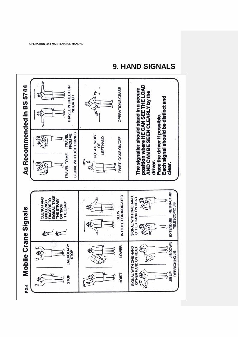
OPERATION and MAINTENANCE MANUAL
Version 01.06 CSD RT 80/81 97
9. HAND SIGNALS