Embed Size (px)
Citation preview

Document No H15
abc OPERATING, INSTALLATION & MAINTENANCE MANUAL
FOR
SERIES 210 MK.II SAMPLE PROBE
This Jiskoot Product is designed to provide outstanding service if correctly installed, used and maintained recognising the effects of the process conditions (temperature, pressure, wax/pour point, sediment, etc.). Truly representative sampling of crude oils etc. cannot be achieved by one single product in isolation. A well designed system and operating procedures as laid down in the Sampling Standards ISO 3171, API 8.2 and IP Chapter VI section 2 are mandatory. Please consult Jiskoot for further information and assistance. No part of this document may be reproduced or transmitted in any form or by any means, electronic or mechanical, for any purpose, without the express written permission of Jiskoot Ltd. 2008 Jiskoot Ltd. All rights reserved. Jiskoot Ltd., formerly Jiskoot Autocontrol Ltd., also trades as “Jiskoot” and “ Jiskoot Inc

Document No H15
Series 210 Mk II Sample Probe
\\JISKOOT-BACKUP\TECH\DOCUMENT\210 SAMPLERS\SAMPLE PROBE\MANUALS\210 PROBE VER 13.DOC
def
TABLE OF CONTENTS
1 INTRODUCTION............................................................................................................................4
2 OPERATING INSTRUCTIONS ......................................................................................................5
3 GLOSSARY OF SPECIAL TERMS.......................... .....................................................................5
4 UTILITIES REFERENCE ...............................................................................................................5
5 FULL FUNCTIONAL DESCRIPTION ........................ ....................................................................6
6 GENERAL ASSEMBLY & BILL OF MATERIAL ................ ..........................................................7
7 INSTALLATION DETAILS............................... ............................................................................10
7.1 SAMPLE PROBE INSTALLATION................................................................................................11 7.2 REMOVING THE SAMPLE PROBE..............................................................................................14 7.3 ANCILLARY EQUIPMENT INSTALLATION ....................................................................................14 7.4 REMOVAL OF ANCILLARY EQUIPMENT......................................................................................15
8 MAINTENANCE AND TROUBLESHOOTING .................... ........................................................15
8.1 HEALTH AND SAFETY PRECAUTIONS .......................................................................................15 8.2 WEEKLY MAINTENANCE..........................................................................................................16 8.3 ANNUAL MAINTENANCE (OR AS DETERMINED BY SITE CONDITIONS) ...........................................16 8.4 GENERAL NOTES ...................................................................................................................16 8.5 OVERHAUL OF SERIES 210 SAMPLER......................................................................................18 8.6 TESTING ................................................................................................................................30
9 FREQUENTLY ASKED QUESTIONS ......................... ................................................................31
9.1 SAMPLER PROBE DOES NOT OPERATE ...................................................................................31 9.2 SAMPLER PROBE OPERATES BUT DOES NOT PRODUCE A SAMPLE ..........................................31 9.3 SAMPLER FAILS TO TAKE ADEQUATE SAMPLE .........................................................................32 9.4 SAMPLER TAKES EXCESSIVE SAMPLE .....................................................................................32 9.5 LEAKS FROM ACTUATOR ........................................................................................................32 9.6 PROCESS FLUID LEAKS ..........................................................................................................33 9.7 VIBRATION .............................................................................................................................33
10 SUB SUPPLIER INFORMATION ........................... .....................................................................33
11 RECOMMENDED SPARES LISTS ........................... ..................................................................34
11.1 SERIES 210, EH & EH-HP MKII SAMPLE PROBE SPARE PARTS...............................................34 11.2 SERIES 210 HP MKII SAMPLE PROBE SPARE PARTS ...............................................................35 11.3 SERIES 210 SHIPBOARD SAMPLE PROBE SPARE PARTS ..........................................................36 11.4 ALTERNATIVE SEALS FOR MTBE & SIMILAR APPLICATIONS......................................................37 11.5 SPECIAL TOOLS .....................................................................................................................37 11.6 ANCILLARY EQUIPMENT ..........................................................................................................37
12 PRODUCT SPECIFIC DRAWINGS .............................................................................................37
13 ADDENDA – 210 2CC SAMPLE PROBE ..................... ..............................................................38
14 RECOMMENDED SPARES 2CC ................................................................................................38
15 DISCLAIMER ......................................... ......................................................................................39
Series 210 Mk II Sample Probe
Issue No 13 Page 4
def
1 Introduction
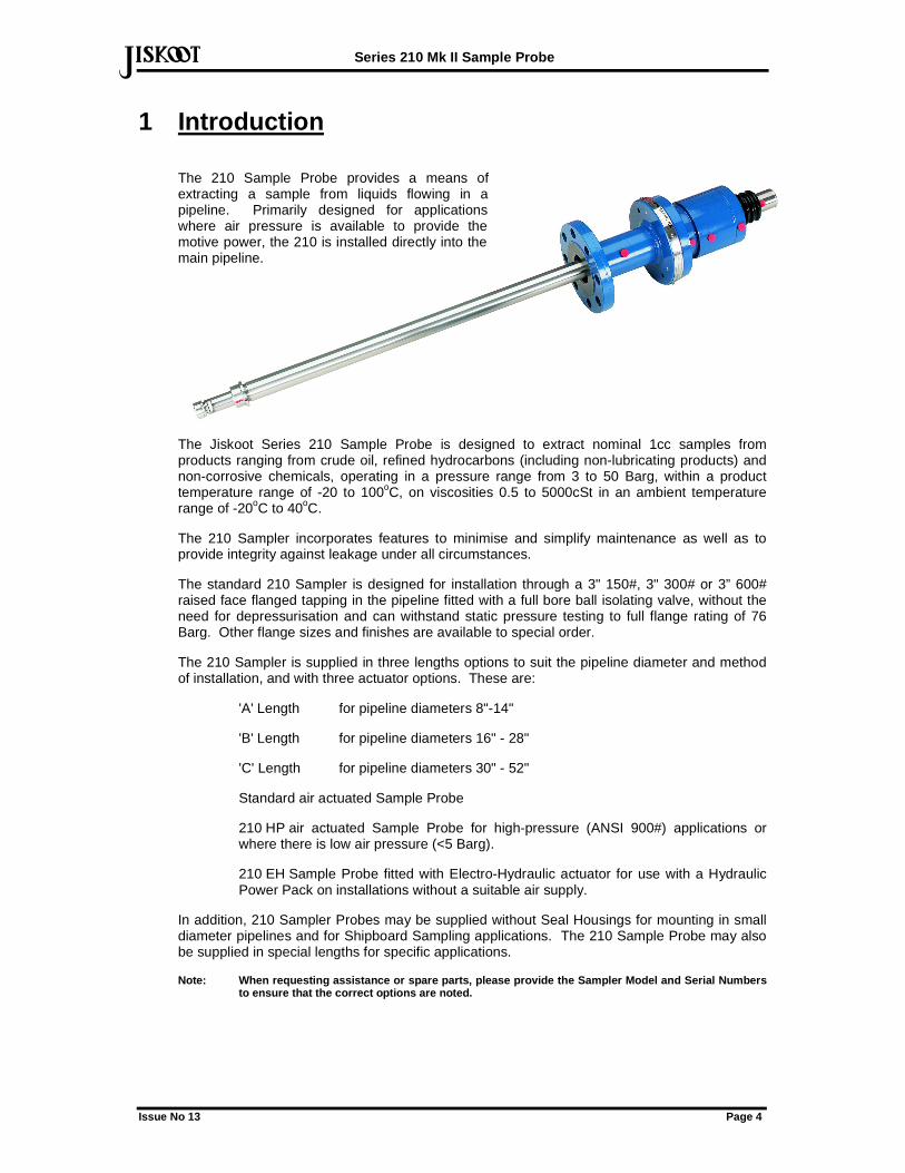
The 210 Sample Probe provides a means of extracting a sample from liquids flowing in a pipeline. Primarily designed for applications where air pressure is available to provide the motive power, the 210 is installed directly into the main pipeline.
The Jiskoot Series 210 Sample Probe is designed to extract nominal 1cc samples from products ranging from crude oil, refined hydrocarbons (including non-lubricating products) and non-corrosive chemicals, operating in a pressure range from 3 to 50 Barg, within a product temperature range of -20 to 100oC, on viscosities 0.5 to 5000cSt in an ambient temperature range of -20oC to 40oC.
The 210 Sampler incorporates features to minimise and simplify maintenance as well as to provide integrity against leakage under all circumstances.
The standard 210 Sampler is designed for installation through a 3" 150#, 3" 300# or 3” 600# raised face flanged tapping in the pipeline fitted with a full bore ball isolating valve, without the need for depressurisation and can withstand static pressure testing to full flange rating of 76 Barg. Other flange sizes and finishes are available to special order.
The 210 Sampler is supplied in three lengths options to suit the pipeline diameter and method of installation, and with three actuator options. These are:
'A' Length for pipeline diameters 8"-14"
'B' Length for pipeline diameters 16" - 28"
'C' Length for pipeline diameters 30" - 52"
Standard air actuated Sample Probe
210 HP air actuated Sample Probe for high-pressure (ANSI 900#) applications or where there is low air pressure (<5 Barg).
210 EH Sample Probe fitted with Electro-Hydraulic actuator for use with a Hydraulic Power Pack on installations without a suitable air supply.
In addition, 210 Sampler Probes may be supplied without Seal Housings for mounting in small diameter pipelines and for Shipboard Sampling applications. The 210 Sample Probe may also be supplied in special lengths for specific applications.
Note: When requesting assistance or spare parts, pl ease provide the Sampler Model and Serial Numbers to ensure that the correct options are noted.
Series 210 Mk II Sample Probe
Issue No 13 Page 5
def
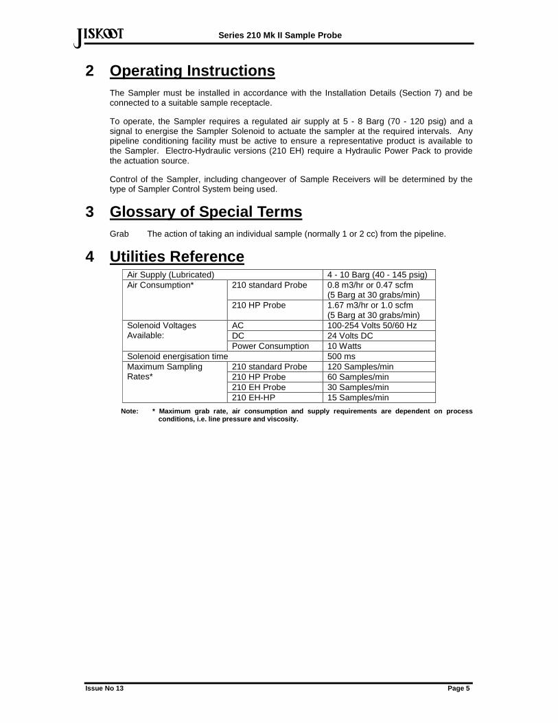
2 Operating Instructions The Sampler must be installed in accordance with the Installation Details (Section 7) and be connected to a suitable sample receptacle.
To operate, the Sampler requires a regulated air supply at 5 - 8 Barg (70 - 120 psig) and a signal to energise the Sampler Solenoid to actuate the sampler at the required intervals. Any pipeline conditioning facility must be active to ensure a representative product is available to the Sampler. Electro-Hydraulic versions (210 EH) require a Hydraulic Power Pack to provide the actuation source.
Control of the Sampler, including changeover of Sample Receivers will be determined by the type of Sampler Control System being used.
3 Glossary of Special Terms Grab The action of taking an individual sample (normally 1 or 2 cc) from the pipeline.
4 Utilities Reference Air Supply (Lubricated) 4 - 10 Barg (40 - 145 psig)
210 standard Probe 0.8 m3/hr or 0.47 scfm (5 Barg at 30 grabs/min)
Air Consumption*
210 HP Probe 1.67 m3/hr or 1.0 scfm (5 Barg at 30 grabs/min)
AC 100-254 Volts 50/60 Hz DC 24 Volts DC
Solenoid Voltages Available:
Power Consumption 10 Watts Solenoid energisation time 500 ms
210 standard Probe 120 Samples/min 210 HP Probe 60 Samples/min 210 EH Probe 30 Samples/min
Maximum Sampling Rates*
210 EH-HP 15 Samples/min
Note: * Maximum grab rate, air consumption and supp ly requirements are dependent on process conditions, i.e. line pressure and viscosity.
Series 210 Mk II Sample Probe
Issue No 13 Page 6
def
5 Full Functional Description
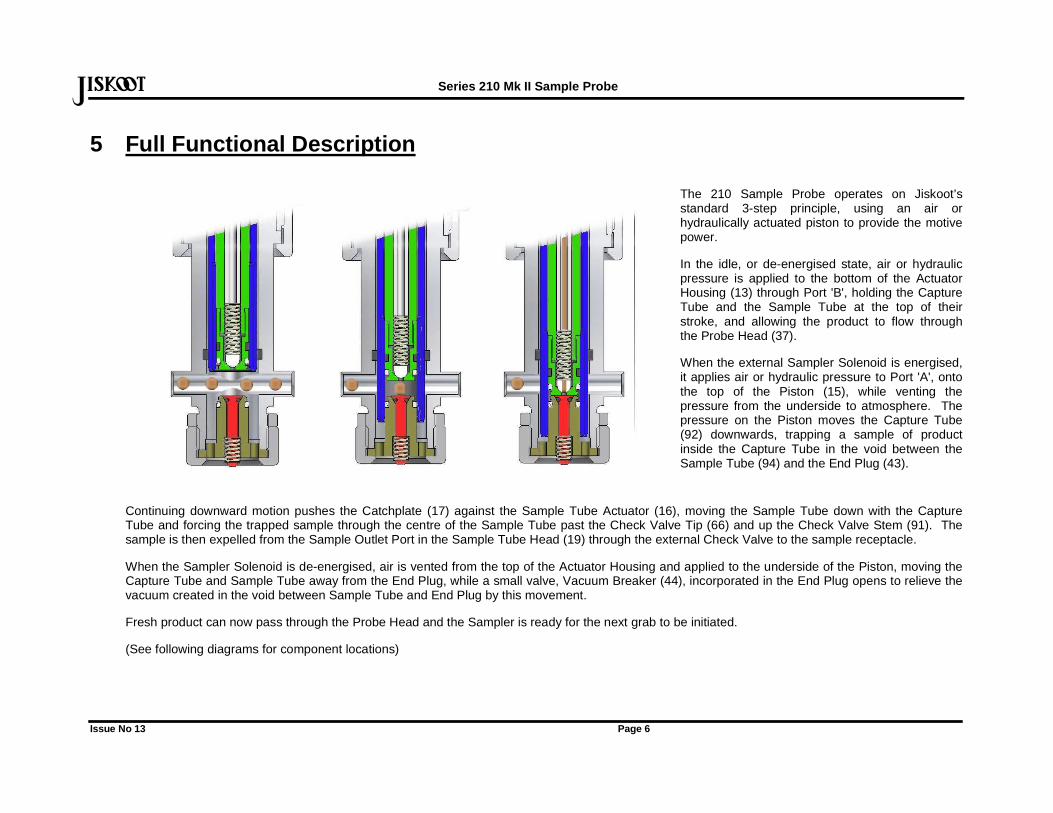
The 210 Sample Probe operates on Jiskoot’s standard 3-step principle, using an air or hydraulically actuated piston to provide the motive power.
In the idle, or de-energised state, air or hydraulic pressure is applied to the bottom of the Actuator Housing (13) through Port 'B', holding the Capture Tube and the Sample Tube at the top of their stroke, and allowing the product to flow through the Probe Head (37).
When the external Sampler Solenoid is energised, it applies air or hydraulic pressure to Port 'A', onto the top of the Piston (15), while venting the pressure from the underside to atmosphere. The pressure on the Piston moves the Capture Tube (92) downwards, trapping a sample of product inside the Capture Tube in the void between the Sample Tube (94) and the End Plug (43).
Continuing downward motion pushes the Catchplate (17) against the Sample Tube Actuator (16), moving the Sample Tube down with the Capture Tube and forcing the trapped sample through the centre of the Sample Tube past the Check Valve Tip (66) and up the Check Valve Stem (91). The sample is then expelled from the Sample Outlet Port in the Sample Tube Head (19) through the external Check Valve to the sample receptacle.
When the Sampler Solenoid is de-energised, air is vented from the top of the Actuator Housing and applied to the underside of the Piston, moving the Capture Tube and Sample Tube away from the End Plug, while a small valve, Vacuum Breaker (44), incorporated in the End Plug opens to relieve the vacuum created in the void between Sample Tube and End Plug by this movement.
Fresh product can now pass through the Probe Head and the Sampler is ready for the next grab to be initiated.
(See following diagrams for component locations)
Series 210 Mk II Sample Probe
Issue No 13 Page 7
def
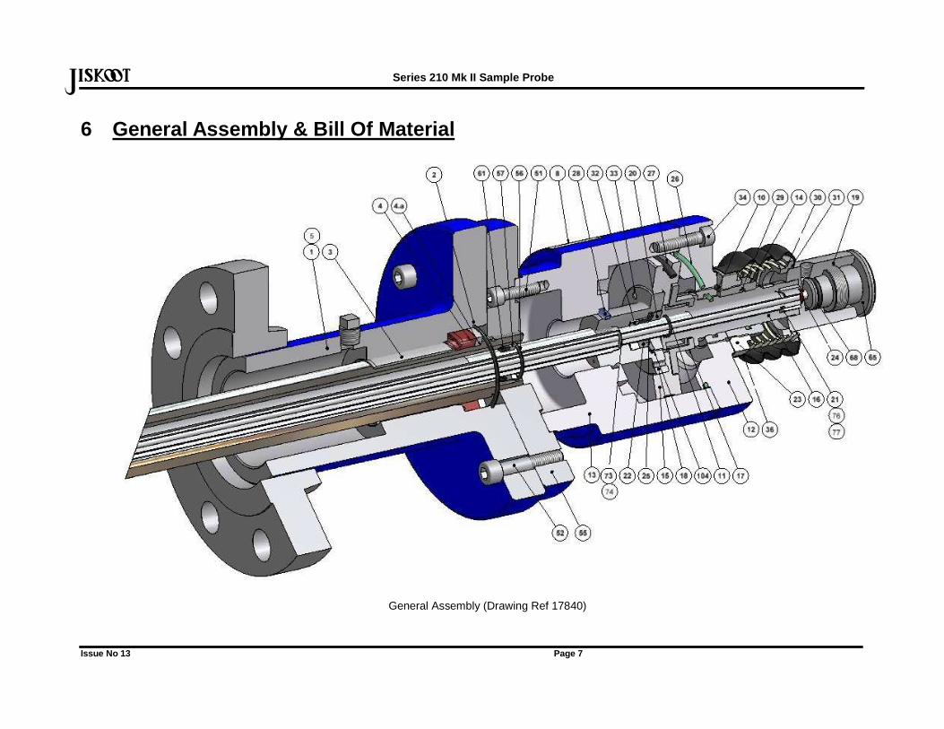
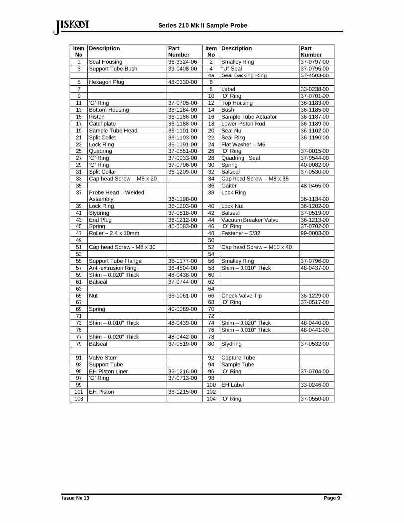
6 General Assembly & Bill Of Material
General Assembly (Drawing Ref 17840)
Series 210 Mk II Sample Probe
Issue No 13 Page 8
def
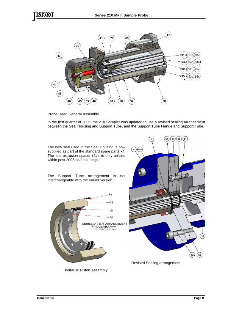
Probe Head General Assembly
In the first quarter of 2006, the 210 Sampler was updated to use a revised sealing arrangement between the Seal Housing and Support Tube, and the Support Tube Flange and Support Tube.
The new seal used in the Seal Housing is now supplied as part of the standard spare parts kit. The anti-extrusion spacer (4a), is only utilised within post 2006 seal housings.
The Support Tube arrangement is not interchangeable with the earlier version.
Revised Sealing arrangement
Hydraulic Piston Assembly
Series 210 Mk II Sample Probe
Issue No 13 Page 9
defItem No
Description Part Number
Item No
Description Part Number
1 Seal Housing 36-3324-06 2 Smalley Ring 37-0797-00 3 Support Tube Bush 39-0408-00 4 “U” Seal 37-0795-00 4a Seal Backing Ring 37-4503-00 5 Hexagon Plug 48-0330-00 6 7 8 Label 33-0238-00 9 10 ’O’ Ring 37-0701-00
11 ’O’ Ring 37-0705-00 12 Top Housing 36-1183-00 13 Bottom Housing 36-1184-00 14 Bush 36-1185-00 15 Piston 36-1186-00 16 Sample Tube Actuator 36-1187-00 17 Catchplate 36-1188-00 18 Lower Piston Rod 36-1189-00 19 Sample Tube Head 36-1101-00 20 Seal Nut 36-1102-00 21 Split Collet 36-1103-00 22 Seal Ring 36-1190-00 23 Lock Ring 36-1191-00 24 Flat Washer – M6 25 Quadring 37-0551-00 26 ’O’ Ring 37-0015-00 27 ’O’ Ring 37-0033-00 28 Quadring Seal 37-0544-00 29 ’O’ Ring 37-0706-00 30 Spring 40-0082-00 31 Split Collar 36-1209-00 32 Balseal 37-0530-00 33 Cap head Screw – M5 x 20 34 Cap head Screw – M8 x 35 35 36 Gaiter 48-0465-00 37 Probe Head – Welded
Assembly 36-1198-00 38 Lock Ring
36-1134-00 39 Lock Ring 36-1203-00 40 Lock Nut 36-1202-00 41 Slydring 37-0518-00 42 Balseal 37-0519-00 43 End Plug 36-1212-00 44 Vacuum Breaker Valve 36-1213-00 45 Spring 40-0083-00 46 ‘O’ Ring 37-0702-00 47 Roller – 2.4 x 10mm 48 Fastener – 5/32 99-0003-00 49 50 51 Cap head Screw - M8 x 30 52 Cap head Screw – M10 x 40 53 54 55 Support Tube Flange 36-1177-00 56 Smalley Ring 37-0796-00 57 Anti-extrusion Ring 36-4504-00 58 Shim – 0.010” Thick 48-0437-00 59 Shim – 0.020” Thick 48-0438-00 60 61 Balseal 37-0744-00 62 63 64 65 Nut 36-1061-00 66 Check Valve Tip 36-1229-00 67 68 ‘O’ Ring 37-0517-00 69 Spring 40-0089-00 70 71 72 73 Shim – 0.010” Thick 48-0439-00 74 Shim – 0.020” Thick 48-0440-00 75 76 Shim – 0.010” Thick 48-0441-00 77 Shim – 0.020” Thick 48-0442-00 78 79 Balseal 37-0519-00 80 Slydring 37-0532-00
91 Valve Stem 92 Capture Tube 93 Support Tube 94 Sample Tube 95 EH Piston Liner 36-1216-00 96 ‘O’ Ring 37-0704-00 97 ‘O’ Ring 37-0713-00 98 99 100 EH Label 33-0246-00
101 EH Piston 36-1215-00 102 103 104 ‘O’ Ring 37-0550-00
Series 210 Mk II Sample Probe
Issue No 13 Page 10
def
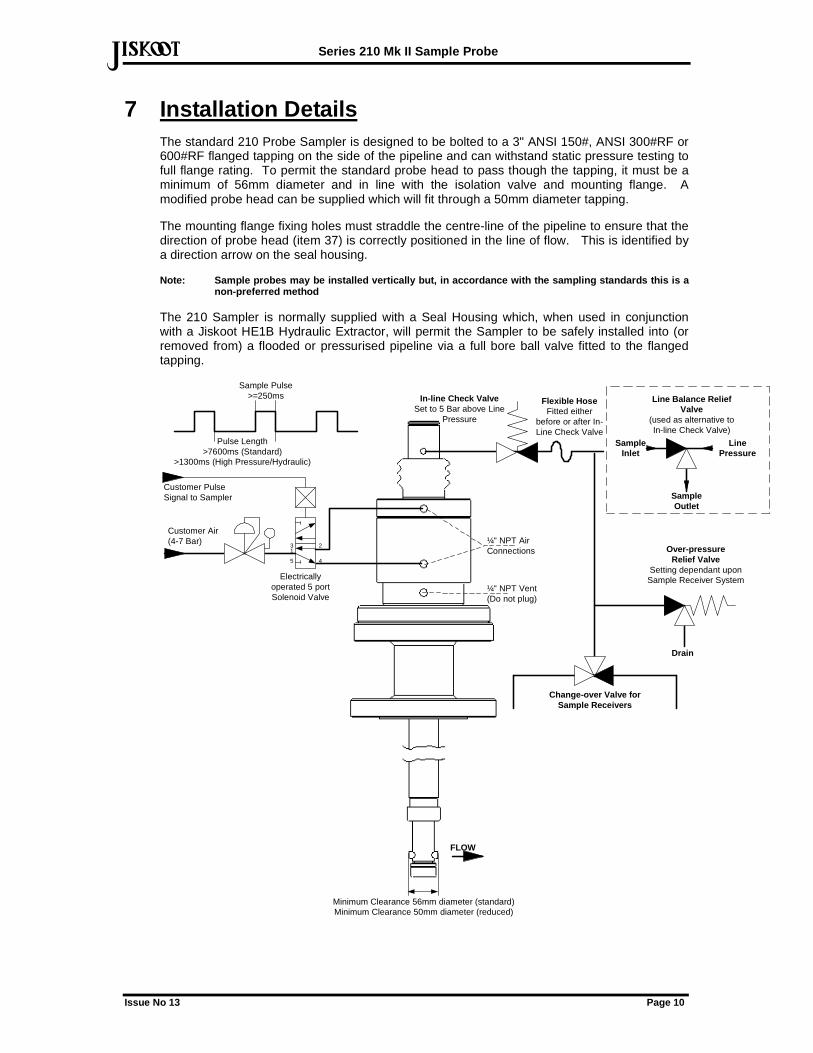
7 Installation Details The standard 210 Probe Sampler is designed to be bolted to a 3" ANSI 150#, ANSI 300#RF or 600#RF flanged tapping on the side of the pipeline and can withstand static pressure testing to full flange rating. To permit the standard probe head to pass though the tapping, it must be a minimum of 56mm diameter and in line with the isolation valve and mounting flange. A modified probe head can be supplied which will fit through a 50mm diameter tapping.
The mounting flange fixing holes must straddle the centre-line of the pipeline to ensure that the direction of probe head (item 37) is correctly positioned in the line of flow. This is identified by a direction arrow on the seal housing.
Note: Sample probes may be installed vertically but , in accordance with the sampling standards this is a non-preferred method
The 210 Sampler is normally supplied with a Seal Housing which, when used in conjunction with a Jiskoot HE1B Hydraulic Extractor, will permit the Sampler to be safely installed into (or removed from) a flooded or pressurised pipeline via a full bore ball valve fitted to the flanged tapping.
Minimum Clearance 56mm diameter (standard)Minimum Clearance 50mm diameter (reduced)
Customer PulseSignal to Sampler
FLOW
Change-over Valve forSample Receivers
Over-pressureRelief Valve
Setting dependant uponSample Receiver System
Drain
31
2
4
Customer Air(4-7 Bar)
Electricallyoperated 5 portSolenoid Valve
¼" NPT AirConnections
¼" NPT Vent(Do not plug)
Line Balance ReliefValve
(used as alternative toIn-line Check Valve)
LinePressure
SampleOutlet
SampleInlet
5
Sample Pulse>=250ms
Pulse Length>7600ms (Standard)
>1300ms (High Pressure/Hydraulic)
In-line Check ValveSet to 5 Bar above Line
Pressure
Flexible HoseFitted either
before or after In-Line Check Valve
Series 210 Mk II Sample Probe
Issue No 13 Page 11
defWhere the Sampler is supplied without the Seal Housing, it is intended for mounting directly onto the flanged tapping on the pipeline.
A Sampler Solenoid Valve must be selected to suit the specific application and will require connecting to suitable supplies via glands and cables appropriate to the hazardous area classification.
A regulated instrument air supply must be connected to the Solenoid and the normally energised outlet connected to Port 'B' of the Sampler. The normally de-energised port of the Solenoid must be connected to Port 'A'. The exhaust port(s) of the Solenoid may be piped away or fitted with silencers as required. (On Electro-Hydraulic applications, the Solenoid is incorporated into the Hydraulic Power Pack.)
The 1/8"NPTF Sample Outlet Port in the Sample Tube Head (19) must be connected to the Sample Receiver System using ¼" or 6mm stainless steel tubing via either an in-line Check Valve or a Jiskoot Line Balanced Relief Valve and a relief valve as shown in the above diagram.
NOTE: To allow for the 19mm movement of the top of the probe at each operation, the in-line Check/Reli ef Valve must either be directly mounted to the Sample Tube Head with a flexible hose immediately after it, or connected to the Sampler via a flexibl e hose.
The Check Valve will normally be set to 5 Bar above the maximum line pressure, ensuring that this is sufficient to allow for any additional pressure increase created by thermal expansion when any isolating valves are closed and the effects of trace heating and or solar energy. If the cracking pressure is set too low, the valve may open under adverse conditions, causing the Sample Receiver System to overfill and the sample to leak through the relief valve to atmosphere.
Where line-balanced, high-pressure sample receivers are being used (i.e. where the sample is being collected at, or close to line pressure), and the installation uses the Swagelok R3A or any similar valves unaffected by back pressure, to avoid placing unnecessary load on the Sampler seals, the Check Valve should be set to operate at 1 Bar. If the valve is found to lift and fill the Sample Receiver due to pressure surges, this setting may be increased slightly.
The relief valve fitted to the sample line is to provide protection to the Sampler in the event of the sampler being operated against a blocked sample line, e.g. without a sample receiver being fitted or with a full sample receiver. This relief valve should be within the maximum pressure rating of the receiver system, but may need to be increased slightly to allow for momentary pressure surges as the sample is being taken.
Ensure that lengths of tubing connecting the sampler to the receiver system are kept to a minimum to minimise "dead" i.e. trapped volume (long lengths of tubing also create extra back pressure and premature seal wear), and that the sample travels downhill at a minimum angle of 15 degrees from the Sampler Outlet to the Receiver to avoid water traps. The sample outlet piping may require heat tracing to prevent blockage.
7.1 Sample Probe Installation
Notes: Do not attempt insertion or withdrawal of th e Standard 210 Sample Probe without the optional 15 4 Series Hydraulic Extractor if the line pressure exc eeds 2.5 Barg (40 psig). At this pressure, approximately 60KgF – 132 Ibf will be produced at the probe head, as such it will not be possible to undertake the operation without risk of damage or i njury to equipment or personnel.
The combined weight of the Sample Probe and the Hy draulic Extractor is approximately 65kg (145lb). Operators must ensure that adequate lifti ng equipment and safety precautions are used to avoid the risk of injury to personnel and damage to equipment whilst the Sample Probe is being installed or extracted.
HE1B Hydraulic Extractors supplied prior to June 2 006 are not designed for use with High Pressure (HP) Sample Probes above 50 BARG (725 PSIG). Extra ctors supplied after from June 2006 (with a diverter valve on the pump) are suitable for use at all line pressures without the need for depressurising (43-0154-00).
The probe has an engineered stop to limit its travel when fully withdrawn from the pipeline.
Series 210 Mk II Sample Probe
Issue No 13 Page 12
def7.1.1 Installation of Sample Probe with HE1B and 15 4 Series Hydraulic Extractor
The 210 Sample Probe should be Installation
with reference to :
H27 Hydraulic Extractor Manual:
Remove the Weatherproof Housing (if supplied) and any ancillary equipment fitted to the Sample Probe by detaching the connections from the Actuator (pneumatic connectors are a push-to-release type) and disconnecting the flexible hose from the Sampler Outlet.
On versions supplied with a Back Pressure Regulator (BPR), disconnect the lower connection to the BPR from the two way valve on the Seal Housing (taking care not to disturb the setting of the bottom nut of the BPR) and close the valve.
The entire assembly may now be released either by removing the bolts or loosening the clamp securing the mounting plate to the Support Tube Flange.
Remove the 4 off M12 (3 off M10 on earlier versions) cap-head screws retaining the Support Tube Flange to the Seal Housing and push the Seal Housing down the Support Tube until the Probe Head is inside the Seal Housing. If the Seal Housing will not slide down the Support Tube, use the Hydraulic Extractor to overcome the friction of the Seal against the Support Tube.
Fit the Hydraulic Extractor to the Support Tube Flange and Seal Housing using four M12 x 25mm long bolts (min 8.8 grade). Connect the high-pressure hose from the pump head end of the Hydraulic Pump to the quick release coupling piped from the bottom of the hydraulic rams, and the hose on the reservoir end of the Pump to the coupling for the top end of the rams.
Close the pressure release valve and pump until the Seal Housing has been moved to the bottom of the Support Tube.
Series 210 Mk II Sample Probe
Issue No 13 Page 13
defDue to the combined weight of the Sample Probe and Hydraulic Extractor, it is recommended that the Extractor be unbolted from the Probe when fitting the Sample Probe to the Isolating Valve.
Locate the Sampler on the Isolating Valve ensuring the flow direction arrow/mark on the Seal Housing is in the direction of flow.
Bolt the Sample Probe to the isolating valve using appropriate gaskets. Ensure that the bleed tappings on the Seal Housing are closed and that suitable ½” NPT plugs are fitted in place of any plastic shipping plugs. Fit the Hydraulic Extractor to the Support Tube Flange and Seal Housing using four M12 x 25mm long bolts.
1) Switch the diverter valve to apply pressure to the top of the hydraulic rams and apply one or two strokes of the Pump to push the Sample Probe towards the isolating valve and pipeline.
2) Fully open the isolating valve.
3) Pump the Sample Probe into the pipeline.
4) Once the Sample Probe has been fully inserted, replace and tighten the cap head screws which attach the support tube flange to the seal housing. The Hydraulic Extractor should now be removed.
Notes: HE1B Extractors supplied before June 2006 do not have a changeover valve and require the high-pressure discharge hose from the Pump to the quick release coupling for the top of the rams and the hose on the reservoir end of the Pump to the co upling for the bottom end of the rams.
It is not recommended that the Hydraulic Extractor remain attached to the Sample Probe when installed in the line.
7.1.2 Manual Installation of Sample Probe
Installation of the 210 Sample Probe is carried out as follows:
Remove the Weatherproof Housing (if supplied) and any ancillary equipment fitted to the Sample Probe by detaching the connections from the Actuator (pneumatic connectors are a push-to-release type), and disconnect the flexible hose from the Sampler Outlet.
On versions supplied with a Back Pressure Regulator (BPR), disconnect the lower connection to the BPR from the two way valve on the Seal Housing (taking care not to disturb the setting of the bottom nut of the BPR) and close the valve.
The entire assembly may now be released either by removing the bolts or loosening the clamp securing the mounting plate to the Support Tube Flange.
Ensure that the valves fitted to the Probe are in the closed position and that suitable ½" NPT plugs are fitted to the Seal Housing vent connections in place of any plastic shipping plugs
Remove the four M12 or three M10 cap head screws (52) securing the Support Tube Flange to the Seal Housing.
Move the Seal Housing down the Support Tube until the Probe Head is inside the Seal Housing.
Mount the Seal Housing Flange centrally on the isolating valve flange with the two pressure tappings and the flow direction arrow/mark in the Seal Housing in line with the flow - this ensures that the pitot entries in the Probe Head of the Sampler are in line with the flow.
Open the pipeline isolation valve. Push the Sample Probe through the valve and into the pipeline.
Refit and tighten the cap head screws to locate the Support Tube Flange to the Seal Housing, ensuring that the arrow in the top of the Support Tube Flange is pointing in the direction of the flow.
Series 210 Mk II Sample Probe
Issue No 13 Page 14
def7.2 Removing the Sample Probe
Notes: Do not attempt insertion or withdrawal of th e Standard 210 Sample Probe without the optional 15 4 Series Hydraulic Extractor if the line pressure exc eeds 2.5 Barg (40 psig). At this pressure, approximately 60KgF – 132 Ibf will be produced at the probe head, as such it will not be possible to undertake the operation without risk of damage or i njury to equipment or personnel.
The combined weight of the Sample Probe and the Hy draulic Extractor is approximately 65kg (145lb). Operators must ensure that adequate lifti ng equipment and safety precautions are used to avoid the risk of injury to personnel and damage to equipment whilst the Sample Probe is being installed or extracted.
The procedure for withdrawing the Sample Probe from a pressurised pipeline is as follows:
1) Turn off any compressed air and electrical supply to the equipment.
2) Close all isolating valves on connections at line pressure. The ball valves fitted to the Sample Probe Head and Seal Housing must be closed.
3) Disconnect all lines to the Sample Probe - compressed air, hydraulic hoses and sample discharge line.
4) Remove the Sampler Housing (where fitted) complete with any insulation and ancillary equipment.
5) Fit the Hydraulic Extractor to the Sample Probe. The top plate of the Extractor is bolted to the top of the Support Tube Flange using two M12 x 25mm long set-screws. The lower plate is bolted to the underneath of the top flange of the Seal Housing also using two M12 x 25mm set-screws. Extractors supplied from June 2006 (Serial No 2006F****) have captive bolts fitted to the assembly.
6) Connect the pump hoses to the Hydraulic Extractor via the quick connect couplings.
7) Move the diverter valve on the pump to apply pressure to the top of the hydraulic cylinders and pump until pressure is felt. This will ensure that the probe remains in contact iwith te seal housing as the fixing bolts are loosened and removed.
8) Because of the effects of stiction between the seal in the Seal Housing and the Support Tube, and to ensure that withdrawal of the Sample Probe is fully under control, carefully loosen - 2-3 turns only - the M12 or M10 cap head screws (52) which attach the Support Tube Flange to the Seal Housing - the heads of these screws are located in the top of the Support Tube Flange. As these screws are loosened, the Sample Probe may move a small amount due to line pressure forcing the Probe out of the line. This may be remedied by operating the Pump to increase the hydraulic pressure to balance the pressures across the rams.
9) Remove the cap head screws (52) completely.
10) Move the diverter valve on the hydraulic pump to apply pressure to the bottom of the hydraulic cylinders valve on the pump. Operate the pump to apply pressure to force the probe out of the pipeline - the hydraulic fluid displaced in the extractor cylinders will be slowly forced back into the reservoir.
11) Once the Sample Probe is fully extracted, close the isolating valve on which it is mounted. Depressurise and bleed the Seal Housing and disconnect the Hydrauic Extractor.
12) The probe may now be removed from the isolating valve for maintenance.
7.3 Ancillary Equipment Installation
The Ancillary Equipment, typically comprising Heater and Thermostat, Air Regulator, Solenoid Valve and External Check Valve, is mounted on the Probe and inside an optional Weatherproof Housing.
Series 210 Mk II Sample Probe
Issue No 13 Page 15
defDepending on the type of Sampler Housing, fit the brackets complete with the Ancillary Equipment to the Sample Probe either by securely bolting the main support plate to the top of the Support Tube Flange using two M12 x 20mm long screws or by tightening the clamp securing the mounting plate to the Support Tube Flange.
Connect the two ports of the Actuator to the Solenoid Valve or Hydraulic Power Pack, ensuring that when the coil of the SOV is de-energised, pressure is applied below the Actuator Piston (Port B).
Connect the outlet of the Sample Probe to the sample receiver.
Note: In order to prevent water drop out, the top o f the Sample Receiver must be below the lowest leve l of the Sample Discharge from the Sampler and any ancil lary equipment. The tubing must slope downwards at approximately 15 o towards the Sample Receiver and be as straight and short as possible.
Heat-trace the tubing to 60oC in any installation where waxy or viscous crude oils are sampled. Use the following table as a guide to tubing size:
Sampler Tubing Length
Up to 200 cSt Over 200 cSt
Up to 1.5m 1/4" O.D. 1/4" O.D.
1.5m to 3m 1/4" O.D 3/8" 0.D.
Over 3m 3/8" O.D. 1/2" O.D.
On air actuated versions, connect the air supply to the inlet port (1/4" NPT) of the pressure regulator.
On EH versions, connect the flexible hydraulic hoses to the Actuator (normally depressurised line to the upper port, Port A).
Connect cable(s) to the junction box through cable glands certified for use in the hazardous area classification. The wiring diagram for the ancillary equipment will be found in Section 10.
Note: The correct rating fuse must be included in t he Solenoid Valve supply circuit.
The bottom port (drain cavity) of the actuator may be connected to a closed drain or a pressure switch if required.
Fit the Weatherproof Housing (if supplied) in position. Slots or holes will have to be made to allow access into the housing for the Actuator supply piping, the Sample Outlet piping and electrical cables. The slots or holes should be made in the housing across the joint between its two halves. This will allow the housing to be completely removed without disconnecting piping or cables. The housing is attached by two M8 x 40 long bolts screwed into nuts attached to the upper bracket. To prevent ingress of water, seal all entries into the Housing using a suitable mastic.
7.4 Removal of Ancillary Equipment
Removal of the ancillary equipment is generally the reverse of the above.
8 Maintenance and Troubleshooting 8.1 Health and Safety Precautions
The Series 210 Sample Probe should only be overhauled by trained and competent personnel. Incorrect assembly of the sampler may result in premature component failure and loss of containment. Jiskoot can provide in-house or on-site courses to ensure that personnel have the necessary training to be able to safely and competently overhaul the equipment.
Series 210 Mk II Sample Probe
Issue No 13 Page 16
defThe Series 210 Sample Probe may be used in applications involving carcinogenic or other hazardous products. Care must be taken to avoid contamination by any product trapped within the internal components that may be released as the Sampler is stripped down.
8.2 Weekly Maintenance
Regular maintenance is limited to draining excess moisture from the air filter/regulator or on EH applications, checking the level in the hydraulic oil reservoir on the Hydraulic Power Pack.
8.3 Annual Maintenance (or as determined by site co nditions)
The Series 210 Probe Sampler is designed to operate continuously for a period of about 1,000,000 grabs or 12 months before a major overhaul, however this service interval will be affected by the type of product being sampled, particularly the amount of particulate matter such as sand, and therefore can not be guaranteed. When used in crude oils with high levels of sediment or from mixed carrier shipments, the maintenance interval may be shortened. The service intervals will therefore need to be determined from the experience gained on the particular application.
The Sampler must be removed from the pipeline and taken to a clean area for servicing.
It is essential that soft vice jaws are used whenever components are required to be held, and that all components, particularly those with sealing faces are thoroughly cleaned of dirt and other contamination by degreasing and drying prior to re-assembly.
A Special Tool Kit, Part Number 45-0126-00, is available to assist in fitting some components and seals. Failure to use the correct tools may damage seals and other components, and will have a direct effect on the future performance of the Sampler
8.4 General Notes
The instructions for strip down and reassembly are for the standard version of the Sampler Probe.
Hydraulically actuated (EH) Sampler Probes may be tested using compressed air or gas instead of hydraulic oil where this is more convenient.
These instructions apply to overhaul of the EH, HP and Shipboard versions as well as the standard 210 air actuated Sampler. Variations are noted in the text of the relevant sections.
The item numbers in brackets throughout the text relate to item numbers of components shown on the drawing referenced at the beginning of that section. To simplify the overhaul instructions, standard drawings and component numbers have been used throughout, but note that some components for EH and HP Samplers differ from the standard. Refer to Section 11 for details of the spares kits and special tools required to overhaul all versions of the Sample Probe.
When requesting assistance or spare parts, please advise the Sampler Model and Serial Numbers to ensure that the correct options are supplied.
The complete overhaul should be carried out in the following order:
Step Description
1) Removal and overhaul of End Plug & Vacuum Breaker
2) Removal of Probe Head
3) Slydring (41) Replacement
4) Removal and overhaul of Seal Housing
5) Removal and overhaul of Check Valve Sub-Assembly
Series 210 Mk II Sample Probe
Issue No 13 Page 17
def6) Removal of Sample Tube Head
7) Removal and overhaul of Actuator Assembly
8) Reassembly of Actuator Bottom Housing & Support Tube Assembly
9) Overhaul of Piston/Sample Tube Actuator/Lower Piston Rod Assembly
10) Reassembly of Piston/Sample Tube Actuator/Lower Piston Rod Assembly
11) Replacement of Piston/Catch Plate/Actuator Assembly
12) Replacement Seal Housing
13) Replacement Probe Head Assembly
NOTE: It is essential that soft vice jaws are used whenever components are required to be held, and th at all components, particularly those with sealing fac es are thoroughly cleaned of dirt and other contamination by degreasing and drying prior to re- assembly. If any of the sliding surfaces or the Support Tube are damaged, leakage will occur from t he seals.
All joints, 'O' Rings and moving parts must be lub ricated on assembly using a general purpose grease such as Castrol “Spheerol B2” grease or an e quivalent lithium based water-resistant grease.
Jiskoot recommend that to prevent seizure, all scr ewed components are lubricated with copper grease on assembly.
Series 210 Mk II Sample Probe
Issue No 13 Page 18
def
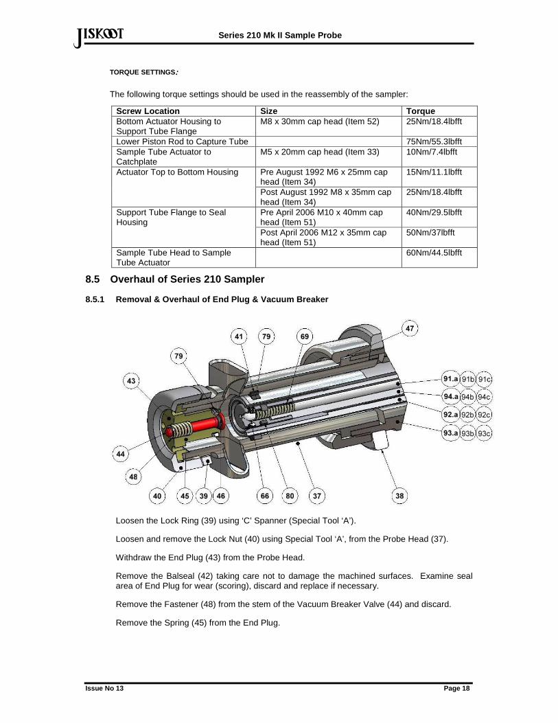
TORQUE SETTINGS: : : :
The following torque settings should be used in the reassembly of the sampler:
Screw Location Size Torque Bottom Actuator Housing to Support Tube Flange
M8 x 30mm cap head (Item 52) 25Nm/18.4lbfft
Lower Piston Rod to Capture Tube 75Nm/55.3lbfft Sample Tube Actuator to Catchplate
M5 x 20mm cap head (Item 33) 10Nm/7.4lbfft
Pre August 1992 M6 x 25mm cap head (Item 34)
15Nm/11.1lbfft Actuator Top to Bottom Housing
Post August 1992 M8 x 35mm cap head (Item 34)
25Nm/18.4lbfft
Pre April 2006 M10 x 40mm cap head (Item 51)
40Nm/29.5lbfft Support Tube Flange to Seal Housing
Post April 2006 M12 x 35mm cap head (Item 51)
50Nm/37lbfft
Sample Tube Head to Sample Tube Actuator
60Nm/44.5lbfft
8.5 Overhaul of Series 210 Sampler
8.5.1 Removal & Overhaul of End Plug & Vacuum Break er
Loosen the Lock Ring (39) using ‘C’ Spanner (Special Tool ‘A’).
Loosen and remove the Lock Nut (40) using Special Tool ‘A’, from the Probe Head (37).
Withdraw the End Plug (43) from the Probe Head.
Remove the Balseal (42) taking care not to damage the machined surfaces. Examine seal area of End Plug for wear (scoring), discard and replace if necessary.
Remove the Fastener (48) from the stem of the Vacuum Breaker Valve (44) and discard.
Remove the Spring (45) from the End Plug.
Series 210 Mk II Sample Probe
Issue No 13 Page 19
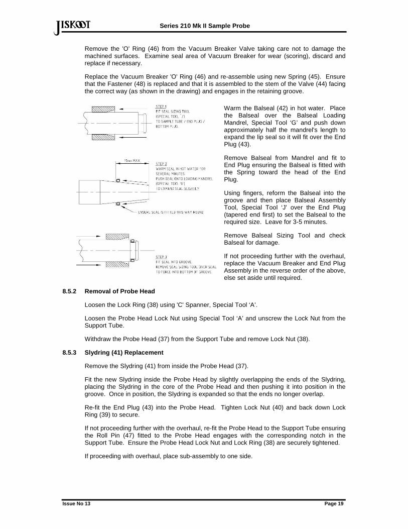
defRemove the 'O' Ring (46) from the Vacuum Breaker Valve taking care not to damage the machined surfaces. Examine seal area of Vacuum Breaker for wear (scoring), discard and replace if necessary.
Replace the Vacuum Breaker 'O' Ring (46) and re-assemble using new Spring (45). Ensure that the Fastener (48) is replaced and that it is assembled to the stem of the Valve (44) facing the correct way (as shown in the drawing) and engages in the retaining groove.
Warm the Balseal (42) in hot water. Place the Balseal over the Balseal Loading Mandrel, Special Tool ‘G’ and push down approximately half the mandrel's length to expand the lip seal so it will fit over the End Plug (43).
Remove Balseal from Mandrel and fit to End Plug ensuring the Balseal is fitted with the Spring toward the head of the End Plug.
Using fingers, reform the Balseal into the groove and then place Balseal Assembly Tool, Special Tool ‘J’ over the End Plug (tapered end first) to set the Balseal to the required size. Leave for 3-5 minutes.
Remove Balseal Sizing Tool and check Balseal for damage.
If not proceeding further with the overhaul, replace the Vacuum Breaker and End Plug Assembly in the reverse order of the above, else set aside until required.
8.5.2 Removal of Probe Head
Loosen the Lock Ring (38) using 'C' Spanner, Special Tool ‘A’.
Loosen the Probe Head Lock Nut using Special Tool ‘A’ and unscrew the Lock Nut from the Support Tube.
Withdraw the Probe Head (37) from the Support Tube and remove Lock Nut (38).
8.5.3 Slydring (41) Replacement
Remove the Slydring (41) from inside the Probe Head (37).
Fit the new Slydring inside the Probe Head by slightly overlapping the ends of the Slydring, placing the Slydring in the core of the Probe Head and then pushing it into position in the groove. Once in position, the Slydring is expanded so that the ends no longer overlap.
Re-fit the End Plug (43) into the Probe Head. Tighten Lock Nut (40) and back down Lock Ring (39) to secure.
If not proceeding further with the overhaul, re-fit the Probe Head to the Support Tube ensuring the Roll Pin (47) fitted to the Probe Head engages with the corresponding notch in the Support Tube. Ensure the Probe Head Lock Nut and Lock Ring (38) are securely tightened.
If proceeding with overhaul, place sub-assembly to one side.
Series 210 Mk II Sample Probe
Issue No 13 Page 20
def
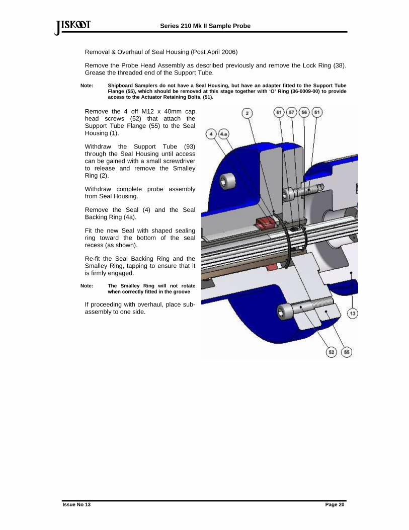
Removal & Overhaul of Seal Housing (Post April 2006)
Remove the Probe Head Assembly as described previously and remove the Lock Ring (38). Grease the threaded end of the Support Tube.
Note: Shipboard Samplers do not have a Seal Housing , but have an adapter fitted to the Support Tube Flange (55), which should be removed at this stage together with ‘O’ Ring (36-0009-00) to provide access to the Actuator Retaining Bolts, (51).
Remove the 4 off M12 x 40mm cap head screws (52) that attach the Support Tube Flange (55) to the Seal Housing (1).
Withdraw the Support Tube (93) through the Seal Housing until access can be gained with a small screwdriver to release and remove the Smalley Ring (2).
Withdraw complete probe assembly from Seal Housing.
Remove the Seal (4) and the Seal Backing Ring (4a).
Fit the new Seal with shaped sealing ring toward the bottom of the seal recess (as shown).
Re-fit the Seal Backing Ring and the Smalley Ring, tapping to ensure that it is firmly engaged.
Note: The Smalley Ring will not rotate when correctly fitted in the groove
If proceeding with overhaul, place sub-assembly to one side.
Series 210 Mk II Sample Probe
Issue No 13 Page 21
def
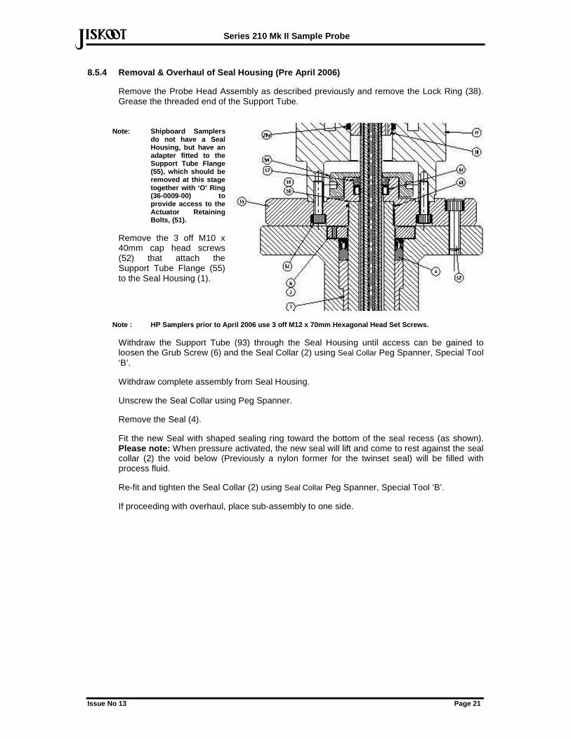
8.5.4 Removal & Overhaul of Seal Housing (Pre April 2006)
Remove the Probe Head Assembly as described previously and remove the Lock Ring (38). Grease the threaded end of the Support Tube.
Note: Shipboard Samplers do not have a Seal Housing, but have an adapter fitted to the Support Tube Flange (55), which should be removed at this stage together with ‘O’ Ring (36-0009-00) to provide access to the Actuator Retaining Bolts, (51).
Remove the 3 off M10 x 40mm cap head screws (52) that attach the Support Tube Flange (55) to the Seal Housing (1).
Note : HP Samplers prior to April 2006 use 3 off M 12 x 70mm Hexagonal Head Set Screws.
Withdraw the Support Tube (93) through the Seal Housing until access can be gained to loosen the Grub Screw (6) and the Seal Collar (2) using Seal Collar Peg Spanner, Special Tool ‘B’.
Withdraw complete assembly from Seal Housing.
Unscrew the Seal Collar using Peg Spanner.
Remove the Seal (4).
Fit the new Seal with shaped sealing ring toward the bottom of the seal recess (as shown). Please note: When pressure activated, the new seal will lift and come to rest against the seal collar (2) the void below (Previously a nylon former for the twinset seal) will be filled with process fluid.
Re-fit and tighten the Seal Collar (2) using Seal Collar Peg Spanner, Special Tool ‘B’.
If proceeding with overhaul, place sub-assembly to one side.
Series 210 Mk II Sample Probe
Issue No 13 Page 22
def
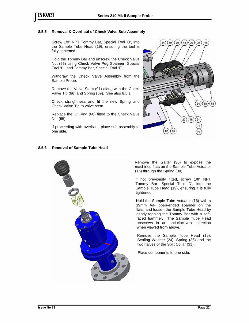
8.5.5 Removal & Overhaul of Check Valve Sub-Assembl y
Screw 1/8” NPT Tommy Bar, Special Tool ‘D’, into the Sample Tube Head (19), ensuring the tool is fully tightened.
Hold the Tommy Bar and unscrew the Check Valve Nut (65) using Check Valve Peg Spanner, Special Tool ‘E’, and Tommy Bar, Special Tool ‘F’.
Withdraw the Check Valve Assembly from the Sample Probe.
Remove the Valve Stem (91) along with the Check Valve Tip (66) and Spring (69). See also 8.5.1
Check straightness and fit the new Spring and Check Valve Tip to valve stem.
Replace the 'O' Ring (68) fitted to the Check Valve Nut (65).
If proceeding with overhaul, place sub-assembly to one side.
8.5.6 Removal of Sample Tube Head
Remove the Gaiter (36) to expose the machined flats on the Sample Tube Actuator (16) through the Spring (30).
If not previously fitted, screw 1/8” NPT Tommy Bar, Special Tool ‘D’, into the Sample Tube Head (19), ensuring it is fully tightened.
Hold the Sample Tube Actuator (16) with a 19mm A/F open-ended spanner on the flats, and loosen the Sample Tube Head by gently tapping the Tommy Bar with a soft-faced hammer. The Sample Tube Head unscrews in an anti-clockwise direction when viewed from above.
Remove the Sample Tube Head (19), Sealing Washer (24), Spring (36) and the two halves of the Split Collar (31).
Place components to one side.
Series 210 Mk II Sample Probe
Issue No 13 Page 23
def
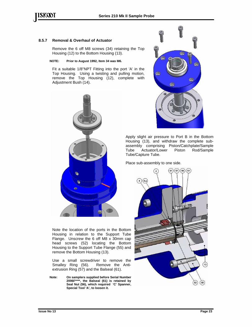
8.5.7 Removal & Overhaul of Actuator
Remove the 6 off M8 screws (34) retaining the Top Housing (12) to the Bottom Housing (13).
NOTE: Prior to August 1992, Item 34 was M6.
Fit a suitable 1/8"NPT Fitting into the port 'A' in the Top Housing. Using a twisting and pulling motion, remove the Top Housing (12), complete with Adjustment Bush (14).
Apply slight air pressure to Port B in the Bottom Housing (13), and withdraw the complete sub-assembly comprising Piston/Catchplate/Sample Tube Actuator/Lower Piston Rod/Sample Tube/Capture Tube.
Place sub-assembly to one side.
Note the location of the ports in the Bottom Housing in relation to the Support Tube Flange. Unscrew the 6 off M8 x 30mm cap head screws (52) locating the Bottom Housing to the Support Tube Flange (55) and remove the Bottom Housing (13).
Use a small screwdriver to remove the Smalley Ring (56). Remove the Anti-extrusion Ring (57) and the Balseal (61).
Note: On samplers supplied before Serial Number 2006F****, the Balseal (61) is retained by Seal Nut (56), which required ‘C’ Spanner, Special Tool ‘A’, to loosen it.
Series 210 Mk II Sample Probe
Issue No 13 Page 24
def8.5.8 Reassembly of Actuator Bottom Housing & Suppo rt Tube Assembly
Note: All components must be thoroughly cleaned and lightly greased on reassembly.
Inspect Support Tube (93) for scoring and ensure Tube is straight. If in doubt, consult Jiskoot for replacement Support Tube/Support Tube Flange sub-assembly.
Using the Upper Capture Tube Seal Assembly Tool, Special Tool ‘M’, fit the new Balseal (61) with the Seal Spring facing towards the bottom of the seal recess in the Support Tube Flange (as shown on the drawing).
Refit the Anti-extrusion Ring (57) and Smalley Ring (56). On samplers supplied before Serial Number 2006F****, the Balseal (61) is retained by Seal Nut (56), which requires ‘C’ Spanner, Special Tool ‘A’ to tighten it.
Clean and examine Bottom Housing for wear.
Fit new Quadring Seal (28).
Note: From 1999, Item 28 on all variants of the 210 Sampler was replaced by a Quadring Seal, Part No . 37-0554-00. This Seal is fully interchangeable wit h all options previously supplied.
Replace Bottom Housing on the Support Tube Flange, ensuring orientation of ports is as found.
Tighten M8 x 30mm screws to specified torque.
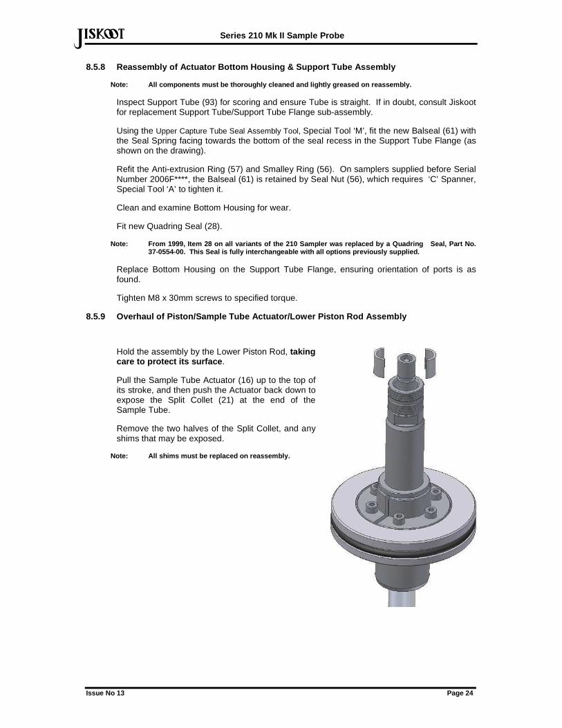
8.5.9 Overhaul of Piston/Sample Tube Actuator/Lower Piston Rod Assembly
Hold the assembly by the Lower Piston Rod, taking care to protect its surface .
Pull the Sample Tube Actuator (16) up to the top of its stroke, and then push the Actuator back down to expose the Split Collet (21) at the end of the Sample Tube.
Remove the two halves of the Split Collet, and any shims that may be exposed.
Note: All shims must be replaced on reassembly.
Series 210 Mk II Sample Probe
Issue No 13 Page 25
def
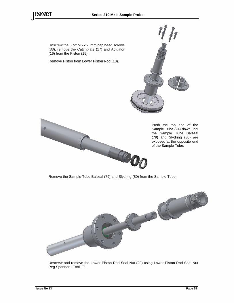
Unscrew the 6 off M5 x 20mm cap head screws (33), remove the Catchplate (17) and Actuator (16) from the Piston (15).
Remove Piston from Lower Piston Rod (18).
Push the top end of the Sample Tube (94) down until the Sample Tube Balseal (79) and Slydring (80) are exposed at the opposite end of the Sample Tube.
Remove the Sample Tube Balseal (79) and Slydring (80) from the Sample Tube.
Unscrew and remove the Lower Piston Rod Seal Nut (20) using Lower Piston Rod Seal Nut Peg Spanner - Tool ‘E’.
Series 210 Mk II Sample Probe
Issue No 13 Page 26
def
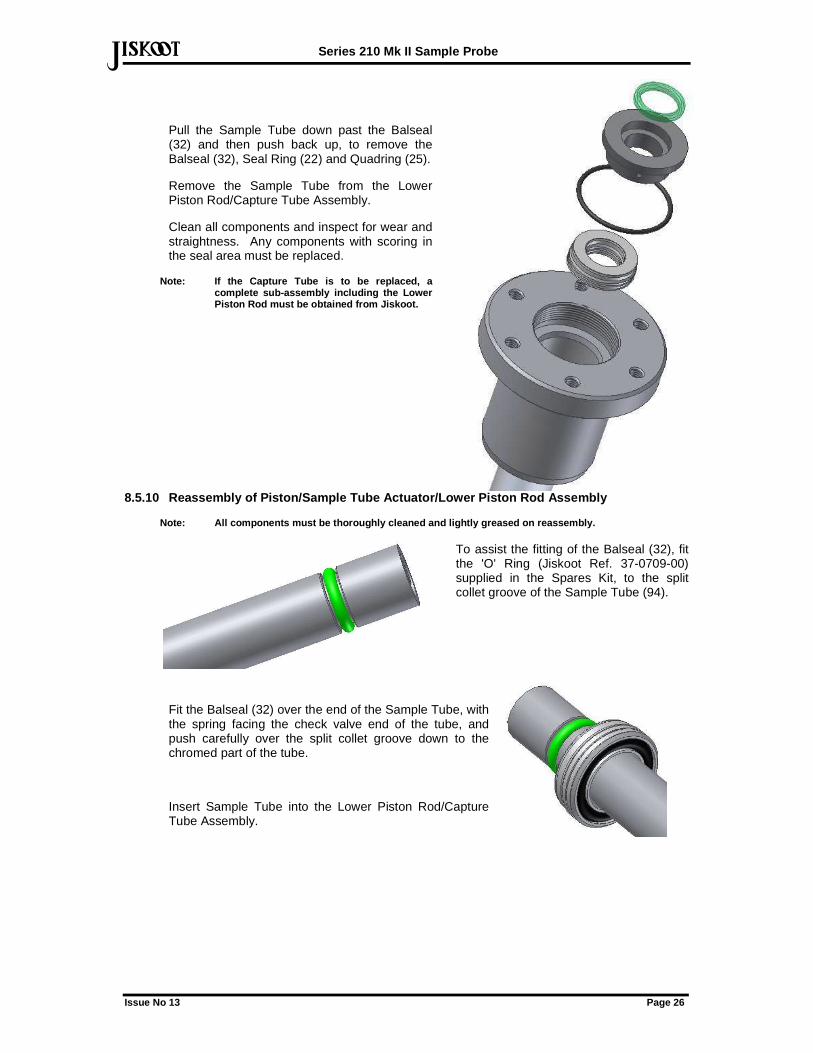
Pull the Sample Tube down past the Balseal (32) and then push back up, to remove the Balseal (32), Seal Ring (22) and Quadring (25).
Remove the Sample Tube from the Lower Piston Rod/Capture Tube Assembly.
Clean all components and inspect for wear and straightness. Any components with scoring in the seal area must be replaced.
Note: If the Capture Tube is to be replaced, a complete sub-assembly including the Lower Piston Rod must be obtained from Jiskoot.
8.5.10 Reassembly of Piston/Sample Tube Actuator/Lo wer Piston Rod Assembly
Note: All components must be thoroughly cleaned and lightly greased on reassembly.
To assist the fitting of the Balseal (32), fit the 'O' Ring (Jiskoot Ref. 37-0709-00) supplied in the Spares Kit, to the split collet groove of the Sample Tube (94).
Fit the Balseal (32) over the end of the Sample Tube, with the spring facing the check valve end of the tube, and push carefully over the split collet groove down to the chromed part of the tube.
Insert Sample Tube into the Lower Piston Rod/Capture Tube Assembly.
Series 210 Mk II Sample Probe
Issue No 13 Page 27
def
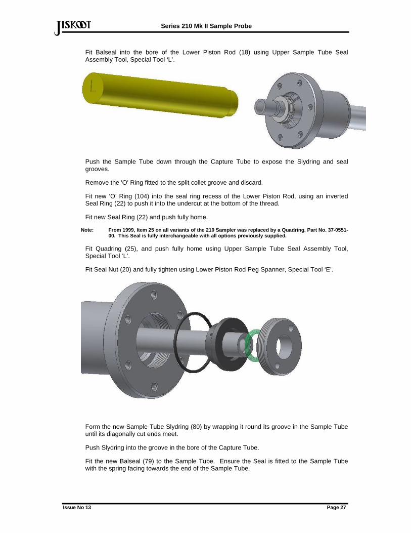
Fit Balseal into the bore of the Lower Piston Rod (18) using Upper Sample Tube Seal Assembly Tool, Special Tool ‘L’.
Push the Sample Tube down through the Capture Tube to expose the Slydring and seal grooves.
Remove the 'O' Ring fitted to the split collet groove and discard.
Fit new ‘O’ Ring (104) into the seal ring recess of the Lower Piston Rod, using an inverted Seal Ring (22) to push it into the undercut at the bottom of the thread.
Fit new Seal Ring (22) and push fully home.
Note: From 1999, Item 25 on all variants of the 210 Sampler was replaced by a Quadring, Part No. 37-05 51-00. This Seal is fully interchangeable with all op tions previously supplied.
Fit Quadring (25), and push fully home using Upper Sample Tube Seal Assembly Tool, Special Tool ‘L’.
Fit Seal Nut (20) and fully tighten using Lower Piston Rod Peg Spanner, Special Tool ‘E’.
Form the new Sample Tube Slydring (80) by wrapping it round its groove in the Sample Tube until its diagonally cut ends meet.
Push Slydring into the groove in the bore of the Capture Tube.
Fit the new Balseal (79) to the Sample Tube. Ensure the Seal is fitted to the Sample Tube with the spring facing towards the end of the Sample Tube.
Series 210 Mk II Sample Probe
Issue No 13 Page 28
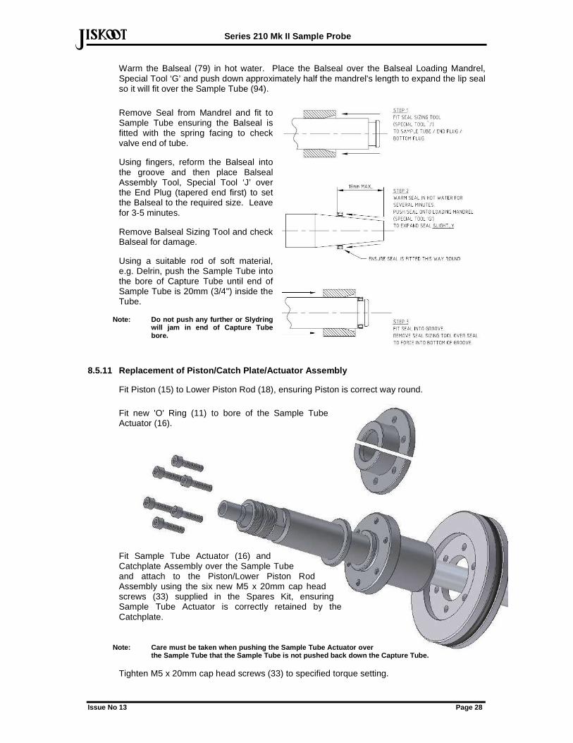
defWarm the Balseal (79) in hot water. Place the Balseal over the Balseal Loading Mandrel, Special Tool ‘G’ and push down approximately half the mandrel's length to expand the lip seal so it will fit over the Sample Tube (94).
Remove Seal from Mandrel and fit to Sample Tube ensuring the Balseal is fitted with the spring facing to check valve end of tube.
Using fingers, reform the Balseal into the groove and then place Balseal Assembly Tool, Special Tool ‘J’ over the End Plug (tapered end first) to set the Balseal to the required size. Leave for 3-5 minutes.
Remove Balseal Sizing Tool and check Balseal for damage.
Using a suitable rod of soft material, e.g. Delrin, push the Sample Tube into the bore of Capture Tube until end of Sample Tube is 20mm (3/4") inside the Tube.
Note: Do not push any further or Slydring will jam in end of Capture Tube bore.
8.5.11 Replacement of Piston/Catch Plate/Actuator A ssembly
Fit Piston (15) to Lower Piston Rod (18), ensuring Piston is correct way round.
Fit new 'O' Ring (11) to bore of the Sample Tube Actuator (16).
Fit Sample Tube Actuator (16) and Catchplate Assembly over the Sample Tube and attach to the Piston/Lower Piston Rod Assembly using the six new M5 x 20mm cap head screws (33) supplied in the Spares Kit, ensuring Sample Tube Actuator is correctly retained by the Catchplate.
Note: Care must be taken when pushing the Sample Tu be Actuator over the Sample Tube that the Sample Tube is not pushed back down the Capture Tube.
Tighten M5 x 20mm cap head screws (33) to specified torque setting.
Series 210 Mk II Sample Probe
Issue No 13 Page 29
def
Note: HP Samplers use M5 x 25mm cap head screws.
Fit the two halves of the Split Collet (21) to the Sample Tube. Push the Split Collet down into the recess in the top of the Sample Tube Actuator. ENSURE ALL ORIGINAL SHIMS (76 & 78) ARE REFITTED UNDER SPLIT COLLET. If this is not done, the Sample Tube may strike the End Plug (43) in the Probe Head when the Sampler is operated and result in damage.
Fit 'O' Ring (27) to Piston.
Note: EH Samplers have two 'O' Rings (96) fitted to the Piston and a Liner (95) fitted to the Actuator Bore, sealed by an 'O' Ring (97).
Liberally grease the bore of the Bottom Housing (13) and the Capture Tube/Piston Assembly.
Slide the assembly through the Bottom Housing into the Support Tube Balseal (61). Carefully push through the Balseal and slide assembly fully home into the Bottom Housing.
8.5.12 Replacement of Top Housing
Note: The Lock Ring (23) on top of the Actuator sho uld not be disturbed. If the Sealing Bush (14) is moved, the grab size of the Sampler will be altered .
Fit the 2 off 'O' Rings (29) in the bore of the Sealing Bush (14).
Fit 'O' Ring (26) in the Top Housing (12).
Liberally grease the internal surface of the Sealing Bush (14), the outside of the Sample Tube Actuator (16) and the internal bore of the Top and Bottom Housings.
Slide the Top Housing over the Sample Tube Actuator and push the two halves of the housing together.
Rotate the Top Housing to align the Actuator Ports.
Fit 6 off M8 x 35mm cap head screws and tighten to specified torque.
Apply slight air pressure to Port B in the Bottom Housing to move the Piston assembly upwards, whilst holding the Sample Tube down in the Sample Tube Actuator to prevent it moving independently of the Sample Tube Actuator.
Fit Check Valve Stem (91), complete with Spring (69) and Check Valve Tip (66), into Sample Tube.
Place new M6 Washer (24) on top of Sample Tube Actuator.
Screw Sample Tube Head (19) onto Sample Tube Actuator and ensure Check Valve Stem moves freely before tightening Sample Tube Head.
Using a 19mm A/F open ended spanner to hold the Sample Tube Actuator (16) and tighten the Sample Tube Head by tapping the 1/8” NPT Tommy Bar, Special Tool ‘D’, previously fitted to the port, using a soft-faced hammer.
Note: This is a pressure retaining joint and must b e tight – refer to torque settings.
Fit new 'O' Ring (68) to the Check Valve Nut (65).
Screw the Check Valve Nut into Sample Tube Head and tighten using Check Valve Nut Peg Spanner - Tool ‘E’ and Tommy Bar, Tool ‘F’.
Note: Early Mk II Samplers may be upgraded by disca rding the circlips (70) and adding a spacer (refer to Jiskoot for advice)
Fit new Spring (30), and Split Collet (31) under the Sample Tube Head.
Series 210 Mk II Sample Probe
Issue No 13 Page 30
defFit new Gaiter over the assembly and secure with a cable tie.
8.5.13 Replacement of Seal Housing
8.5.13.1 Samplers supplied from April 2006
Grease the Support Tube.
Note: Shipboard Samplers do not have a Seal Housing , but have an Adapter fitted to the Support Tube Flange, which should be refitted at this stage usin g a new 'O' Ring, Part Number 37-0009-00.
Holding the Seal Housing in a vice, and ensuring the Sampler Assembly is adequately supported so as not to bend the Support Tube or damage any components, carefully insert the Support Tube through the Seal in the Seal Housing so as to leave a 25mm (1”) gap between the Seal Housing and the Support Tube Flange.
Attach the Support Tube Flange to the Seal Housing ensuring the flow arrow or groove on the Support Tube Flange is aligned with the ¼” NPT tapping in the Seal Housing.
Secure the Support Tube Flange to the Seal Housing, using 4 off M12 x 40mm cap head screws, tightened to the specified torque.
8.5.13.2 Samplers supplied before April 2006
Grease the Support Tube.
Note: Shipboard Samplers do not have a Seal Housing , but have an Adapter fitted to the Support Tube Flange, which should be refitted at this stage usin g a new 'O' Ring, Part Number 37-0009-00.
Holding the Seal Housing in a vice, and ensuring the Sampler Assembly is adequately supported so as not to bend the Support Tube or damage any components, carefully insert the Support Tube through the Seal in the Seal Housing so as to leave a 25mm (1”) gap between the Seal Housing and the Support Tube Flange.
Attach the Support Tube Flange to the Seal Housing ensuring the flow arrow or mark on the Support Tube Flange is aligned with the ¼” NPT tapping in the Seal Housing.
Secure the Support Tube Flange to the Seal Housing, using 4 off M12 x 40mm cap head screws, tightened to the specified torque.
8.5.14 Replacement of Probe Head
Fully screw Lock Ring (38) onto Support Tube (93).
Refit the Probe Head Assembly to the Support Tube (93), ensuring Pin (47) aligns with notch in Support Tube.
Fully tighten Probe Head (37) and Lock Ring (38) using C Spanner, Tool ‘A’.
Screw Lock Ring (39) fully onto Probe Head (37).
Push End Plug/Vacuum Breaker Assembly into the Probe Head, and secure with Lock Nut (40). Tighten using C Spanner, Tool ‘A’.
Screw Lock Ring (38) down onto Lock Nut (40) and tighten using C Spanner, Tool ‘A’.
8.6 Testing
It is recommended that where a test facility is available, the Sampler is pressure tested and re-calibrated prior to returning to service.
Series 210 Mk II Sample Probe
Issue No 13 Page 31
def
9 Frequently Asked Questions 9.1 Sampler Probe Does Not Operate
Check that all actuator and electrical connections are secure and correct.
Check that the actuator pressure, indicated on the air regulator or Hydraulic Power Pack discharge pressure gauge is between 5-6 Barg, re-adjust as required.
Check that the three-way valve between the Sample Outlet and the Check Valve or Back Pressure Regulator (where fitted) is open (the arrow on the handle is pointing toward the valve port connected to the flexible hose).
Ensure that the electrical pulse signal supplied to the SOV is the correct duration (500 milli-second minimum for air, 1 second minimum for hydraulic applications).
If the Sample Tube Head moves slightly, the sample outlet is obstructed. Check that the Back Pressure Regulator (where fitted) is correctly adjusted (refer to BPR Handbook) and that the line to the Sample Receiver is not blocked.
A blockage may have formed within the Sample Probe.
9.2 Sampler Probe Operates But Does Not Produce A S ample
Check all valves are open and that there is fluid in the pipeline.
Check Sampler Controller is demanding a grab and that any interposing relays are operating satisfactorily.
Is solenoid being energised? - Check Solenoid Fuse and operate manually where solenoid has manual override facility.
Check that the Solenoid Valve is energised for minimum of 0.5-1.0 second each cycle. Short cycling will prevent the actuator from stroking fully.
Check that Sample Receiver is not either full, blocked by wax, or isolated (Carefully loosen 1/8" connections in sample discharge tubing to test).
Ensure that the Check Valve Nut (65) is turned fully clockwise so that the Check Valve Spring (69) is fully loaded.
Ensure the Actuator pressure is correct. If the pressure is too low, the Actuator will not stroke fully. Check the stroke of the Actuator is correct - the Sample Tube Head should move approximately 9mm.
Failure of either the Lower Capture Tube Seal (42), the Vacuum Breaker 'O' Ring (46), (fitted to the Probe Head), or the Check Check Valve Tip (66) will cause a reduction or loss of sample grab volume. The following test may be carried out to ensure that they are sealing correctly.
NOTE: Prior to performing this test, ensure that th e sampler is full of fluid by rapidly operating the sampler (30 cycles).
IMPORTANT: THIS TEST MUST BE CARRIED OUT WITH GREAT CARE BECAUSE THE SAMPLER IS CAPABLE OF DEVELOPING VERY HIGH SAMPLE DISCHARGE PRESSURES.
Connect a pressure gauge (0 to 400 Barg/6000 psig) to the Sample Outlet Port of the Sampler. It is recommended that a hydraulic hose is used to connect the pressure gauge. This will act as a hydraulic accumulator to dampen the pressure pulse as each sample grab is ejected.
Series 210 Mk II Sample Probe
Issue No 13 Page 32
defOperate the Sampler ONE GRAB AT A TIME by manually closing the Sample Solenoid relay contacts in the safe area. Each time the Sampler is operated, a pressure increase (approx. 21 Bar/300 psi) should be produced as the pressure of the isolated sample grab is raised to force it through the Check Valve. After a small number of operations, the Sampler should be capable of generating a sample pressure of 140Bar/2000psi. This will only occur if the Capture Tube Seal and Vacuum Breaker are sealing correctly.
STOP OPERATING THE SAMPLER ONCE THE SAMPLE DISCHARG E PRESSURE HAS REACHED 140BARG/2000PSIG . The pressure shown on the pressure gauge should be maintained. This will only occur if the Check Valve is sealing correctly. The pressure will drop if the check valve is leaking. If the pressure only drops very slowly (say 10% in 5 minutes or in maximum interval between grabs if longer), this indicates a very small leak through the Check Valve, which should not affect the sample grab volume of the Sampler
The integrity of the check valve may also be checked by the following technique if the line pressure is below 200 psig, as the back pressure exerted by the check valve spring will hold back this pressure.
Remove the plug from the purge side of the three-way valve and place a receptacle under the outlet. When the three-way valve is turned to purge, no oil should flow.
Manually initiate grabs and ensure that the flow of oil ceases after each grab. This indicates that the valve is seating correctly.
9.3 Sampler Fails To Take Adequate Sample
Check Sample Receiver is not full or the sample outlet piping blocked through waxing.
Check the external Check Valve fitted to Sampler Outlet Adapter is set to 5 Bar above line pressure for normal low-pressure receiver systems and to 1 Bar where high pressure sample receivers are being used. If pressure is too high, excessive wear will be caused to the Sampler internal seals.
Check that the relief valve fitted to the sample discharge lines is not passing.
Ensure that the Sampler Controller is not either demanding too fast a sample grab rate (120 grabs per minute maximum), or that the signal to the solenoid is too short and not allowing the Actuator to travel to the full extent of it's stroke.
Check that the air supply is at the correct pressure and capacity to operate the Probe (Refer to Utilities Section).
If the above are satisfactory, then the Sampler will require a change of internal seals.
9.4 Sampler Takes Excessive Sample
Check the external Check Valve fitted to Sampler Outlet Adapter is set to 5 Bar above line pressure for normal low-pressure receiver systems and to 1 Bar where high pressure sample receivers are being used. If pressure is too low, then the internal Check Valve may be lifting, allowing sample to pass at all times.
9.5 Leaks From Actuator
Leaks will occur from the Actuator between the Top and Bottom Housings if the 'O' Ring (26) fitted to the Top Housing is damaged.
Leaks from the Actuator between the Sample Tube Actuator and the grab size Adjustment Bush (14) indicate the 'O' Rings (29) are worn or damaged.
If the 'O' Ring (10) is damaged the Actuator will leak between the Top Housing and grab size Adjustment Bush.
Series 210 Mk II Sample Probe
Issue No 13 Page 33
defOn EH Sample Probes, oil leaks from the Actuator between the Sample Tube Actuator and the Sample Tube Head indicate the 'O' Ring (11) is damaged.
Air/hydraulic oil leaks will occur from between the Bottom Housing and the Lower Piston Rod (via the drain port) if Quadring Seal (28) is worn or damaged.
Air/hydraulic oil will leak from the drain hole in the Bottom Housing (via the drain port) under one or more of the following conditions:
The Quadring Seal (25) fitted between the Seal Ring and the Lower Piston Rod is worn or damaged.
1) The Seal Nut (20) fitted to the Lower Piston Rod is not properly tightened.
2) The mating face of the Seal Ring (22) and/or the Lower Piston Rod is damaged and does not seal properly.
Dismantle the Actuator (see Section 8.5) and inspect the 'O' Rings. If the 'O' rings are worn or damaged, replacement 'O' Rings must be fitted.
9.6 Process Fluid Leaks
The Series 210 Sampler Probe has been designed so that any seal failures will result in flow from the drain tapping in the Actuator. The following failures may be difficult to observe without dismantling the Probe.
Fluid will leak from the drain hole in the Lower Piston Rod if both the Sample Tube Seal (79) and the Balseal (32) fitted to the Lower Piston Rod are worn or damaged.
Remove Sample Tube Seal and dismantle the Actuator (see Section 8.5.7). Inspect the seals. If the seals are worn or damaged, replacement seals must be fitted.
Fluid will leak from between the Capture Tube and the Seal Nut (56) fitted to the Support Tube Flange if the Capture Tube Upper Seal (61) is worn or damaged.
Remove and inspect the Capture Tube Seal. If the seal is worn or damaged, a replacement seal must be fitted.
Fluid will leak from between the Support Tube Flange and the top flange of the Seal Housing if the Seal (4) fitted to the Seal Housing is worn or damaged.
Remove and inspect the Seal (see Section 8.5.4). If the Seal is worn or damaged, a replacement seal must be fitted.
9.7 Vibration
Vibration is usually the result of excessively high pipeline velocities. Refer to the installation drawings for maximum recommended line velocities.
10 Sub Supplier Information The following sub-supplied items are used in the 210 Sample Probe:
Sampler Solenoid Valve (selected to suit application specific hazardous area requirements and power supply).
Air regulator.
Neither of the above contains any user serviceable parts.
The following Jiskoot Products may be supplied for use with the Series 210 Sample Probe:
Series 210 Mk II Sample Probe
Issue No 13 Page 34
defHydraulic Power Pack (EH versions) - refer to Power Pack Handbook.
154Series Hydraulic Extractor - refer to Hydraulic Extractor Handbook.
Line Balanced Relief Valve.
11 Recommended Spares Lists When requesting assistance or spare parts, please advise the Sampler Model and Serial Numbers to ensure that the correct options are supplied.
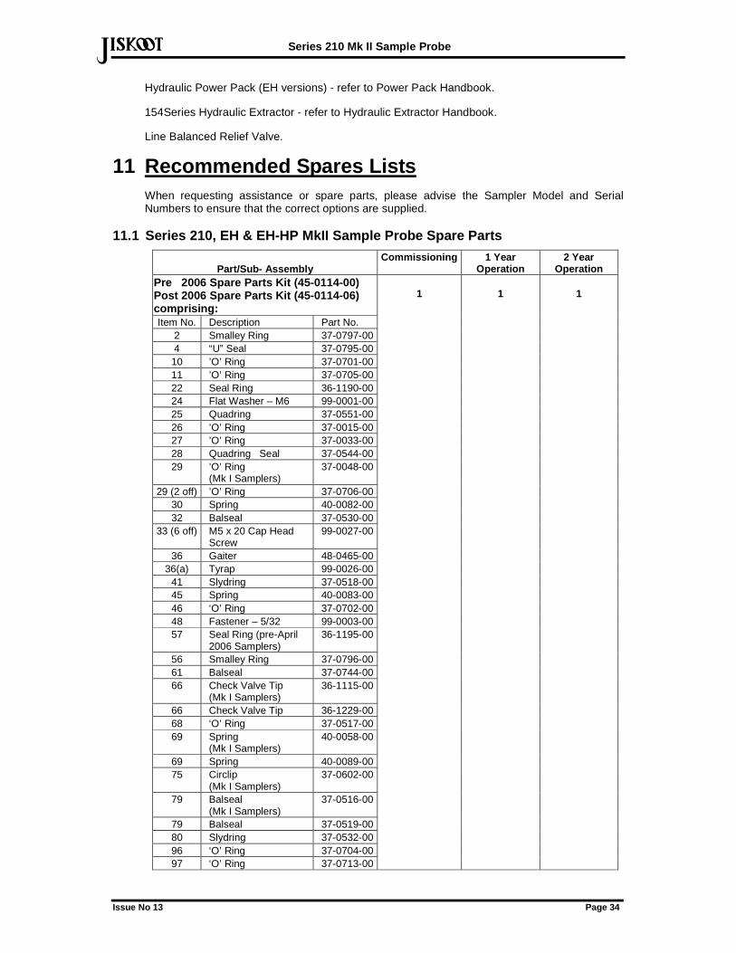
11.1 Series 210, EH & EH-HP MkII Sample Probe Spare Parts
Part/Sub- Assembly Commissioning 1 Year
Operation 2 Year
Operation Pre 2006 Spare Parts Kit (45-0114-00) Post 2006 Spare Parts Kit (45-0114-06) comprising: Item No. Description Part No.
2 Smalley Ring 37-0797-00 4 “U” Seal 37-0795-00 10 ’O’ Ring 37-0701-00 11 ’O’ Ring 37-0705-00 22 Seal Ring 36-1190-00 24 Flat Washer – M6 99-0001-00 25 Quadring 37-0551-00 26 ’O’ Ring 37-0015-00 27 ’O’ Ring 37-0033-00 28 Quadring Seal 37-0544-00 29 ’O’ Ring
(Mk I Samplers) 37-0048-00
29 (2 off) ’O’ Ring 37-0706-00 30 Spring 40-0082-00 32 Balseal 37-0530-00
33 (6 off) M5 x 20 Cap Head Screw
99-0027-00
36 Gaiter 48-0465-00 36(a) Tyrap 99-0026-00
41 Slydring 37-0518-00 45 Spring 40-0083-00 46 ‘O’ Ring 37-0702-00 48 Fastener – 5/32 99-0003-00 57 Seal Ring (pre-April
2006 Samplers) 36-1195-00
56 Smalley Ring 37-0796-00 61 Balseal 37-0744-00 66 Check Valve Tip
(Mk I Samplers) 36-1115-00
66 Check Valve Tip 36-1229-00 68 ‘O’ Ring 37-0517-00 69 Spring
(Mk I Samplers) 40-0058-00
69 Spring 40-0089-00 75 Circlip
(Mk I Samplers) 37-0602-00
79 Balseal (Mk I Samplers)
37-0516-00
79 Balseal 37-0519-00 80 Slydring 37-0532-00 96 ‘O’ Ring 37-0704-00 97 ‘O’ Ring 37-0713-00
1
1
1
Series 210 Mk II Sample Probe
Issue No 13 Page 35
def
Part/Sub- Assembly Commissioning 1 Year
Operation 2 Year
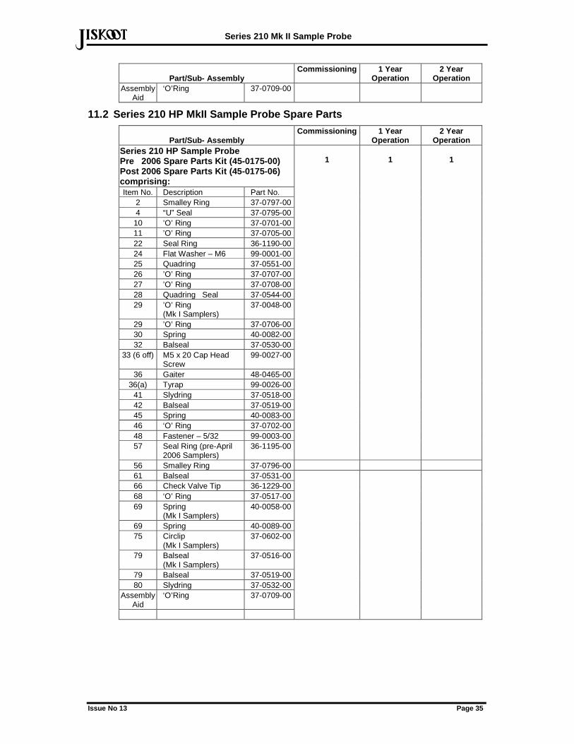
Operation Assembly
Aid ‘O’Ring 37-0709-00
11.2 Series 210 HP MkII Sample Probe Spare Parts
Part/Sub- Assembly Commissioning 1 Year
Operation 2 Year
Operation Series 210 HP Sample Probe Pre 2006 Spare Parts Kit (45-0175-00) Post 2006 Spare Parts Kit (45-0175-06) comprising: Item No. Description Part No.
2 Smalley Ring 37-0797-00 4 “U” Seal 37-0795-00 10 ’O’ Ring 37-0701-00 11 ’O’ Ring 37-0705-00 22 Seal Ring 36-1190-00 24 Flat Washer – M6 99-0001-00 25 Quadring 37-0551-00 26 ’O’ Ring 37-0707-00 27 ’O’ Ring 37-0708-00 28 Quadring Seal 37-0544-00 29 ’O’ Ring
(Mk I Samplers) 37-0048-00
29 ’O’ Ring 37-0706-00 30 Spring 40-0082-00 32 Balseal 37-0530-00
33 (6 off) M5 x 20 Cap Head Screw
99-0027-00
36 Gaiter 48-0465-00 36(a) Tyrap 99-0026-00
41 Slydring 37-0518-00 42 Balseal 37-0519-00 45 Spring 40-0083-00 46 ‘O’ Ring 37-0702-00 48 Fastener – 5/32 99-0003-00 57 Seal Ring (pre-April
2006 Samplers) 36-1195-00
1
1
1
56 Smalley Ring 37-0796-00 61 Balseal 37-0531-00 66 Check Valve Tip 36-1229-00 68 ‘O’ Ring 37-0517-00 69 Spring
(Mk I Samplers) 40-0058-00
69 Spring 40-0089-00 75 Circlip
(Mk I Samplers) 37-0602-00
79 Balseal (Mk I Samplers)
37-0516-00
79 Balseal 37-0519-00 80 Slydring 37-0532-00
Assembly Aid
‘O’Ring 37-0709-00
Series 210 Mk II Sample Probe
Issue No 13 Page 36
def
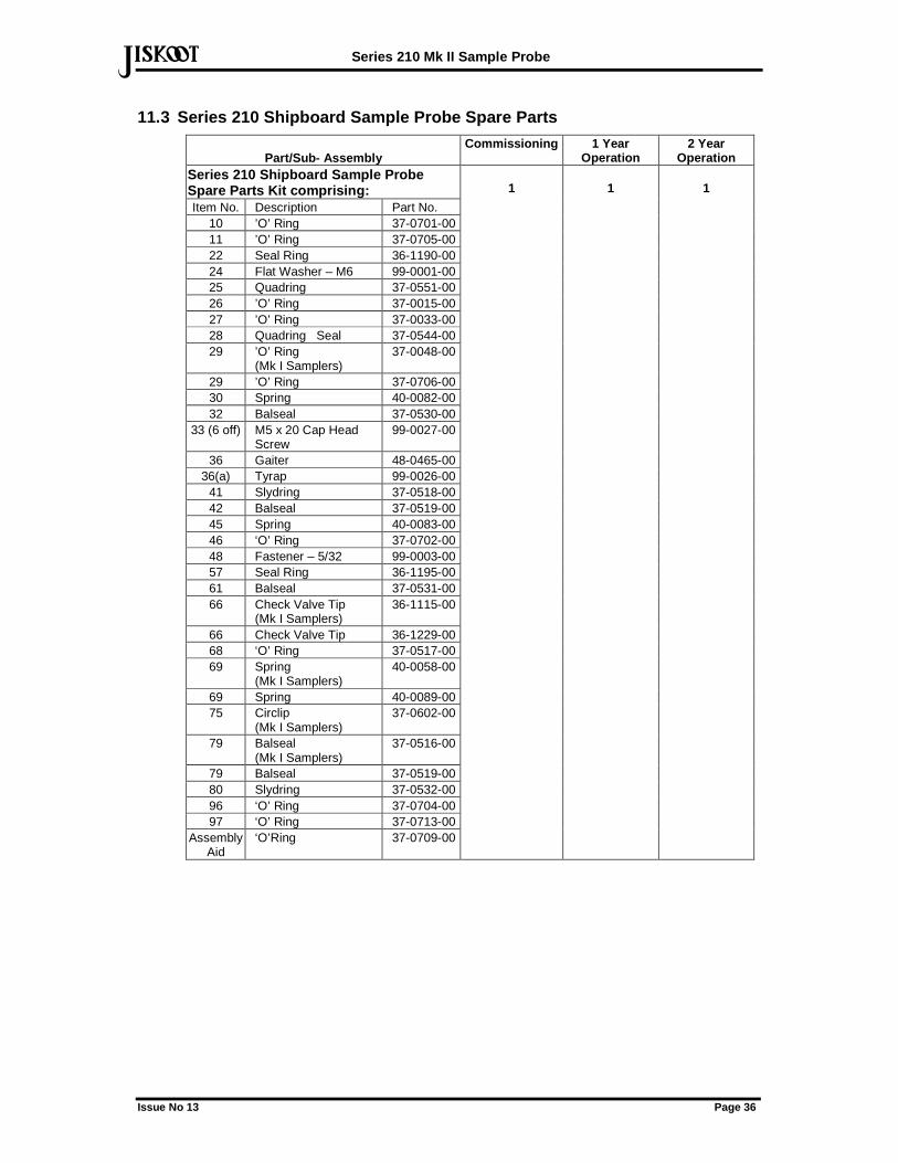
11.3 Series 210 Shipboard Sample Probe Spare Parts
Part/Sub- Assembly Commissioning 1 Year
Operation 2 Year
Operation Series 210 Shipboard Sample Probe Spare Parts Kit comprising: Item No. Description Part No.
10 ’O’ Ring 37-0701-00 11 ’O’ Ring 37-0705-00 22 Seal Ring 36-1190-00 24 Flat Washer – M6 99-0001-00 25 Quadring 37-0551-00 26 ’O’ Ring 37-0015-00 27 ’O’ Ring 37-0033-00 28 Quadring Seal 37-0544-00 29 ’O’ Ring
(Mk I Samplers) 37-0048-00
29 ’O’ Ring 37-0706-00 30 Spring 40-0082-00 32 Balseal 37-0530-00
33 (6 off) M5 x 20 Cap Head Screw
99-0027-00
36 Gaiter 48-0465-00 36(a) Tyrap 99-0026-00
41 Slydring 37-0518-00 42 Balseal 37-0519-00 45 Spring 40-0083-00 46 ‘O’ Ring 37-0702-00 48 Fastener – 5/32 99-0003-00 57 Seal Ring 36-1195-00 61 Balseal 37-0531-00 66 Check Valve Tip
(Mk I Samplers) 36-1115-00
66 Check Valve Tip 36-1229-00 68 ‘O’ Ring 37-0517-00 69 Spring
(Mk I Samplers) 40-0058-00
69 Spring 40-0089-00 75 Circlip
(Mk I Samplers) 37-0602-00
79 Balseal (Mk I Samplers)
37-0516-00
79 Balseal 37-0519-00 80 Slydring 37-0532-00 96 ‘O’ Ring 37-0704-00 97 ‘O’ Ring 37-0713-00
Assembly Aid
‘O’Ring 37-0709-00
1
1
1
Series 210 Mk II Sample Probe
Issue No 13 Page 37
def
11.4 Alternative Seals for MTBE & Similar Applicati ons
Part/Sub- Assembly Commissioning 1 Year
Operation 2 Year
Operation Alternative 'Kalrez' Seals for MTBE & similar applications
Item No. Description 25 ‘O’ Ring (Replaces 37-0037-00) 46 ‘O’ Ring (Replaces 37-0702-00) 68 ‘O’ Ring (Replaces 37-0517-00) 89 ‘O’ Ring (Replaces 37-0009-00
in Shipboard Sampler) 66 Check Valve Tip (Replaces 36-
1229-00)
1 1 1
11.5 Special Tools
Part/Sub- Assembly Commissioning 1 Year
Operation 2 Year
Operation Special Tool Kit (45-0126-00) comprising:
Description Part No. ‘C’ Spanners 36-2000 Seal Collar Peg Spanner - Tool ‘B’
36-2011-00
1/8” NPT Tommy Bar - Tool ‘D’ 36-2010-00 Check Valve Nut / Lower Piston Rod Seal Nut Peg Spanner - Tool ‘E’
36-2004-00
Tommy Bar - Tool ‘F’ 36-2005-00 Balseal Loading Mandrel - Tool ‘G’
36-2006-00
Balseal Sizing Tool - Tool ‘J’ 36-2017-00 Upper Sample Tube Seal Assembly Tool - Tool ‘L’
36-2015-00
Upper Capture Tube Seal Assembly Tool - Tool ‘M’
36-2016-00
1
-
-
11.6 Ancillary Equipment
Part/Sub- Assembly
Commissioning 1 Year Operation
2 Year Operation
Solenoid Coil (to suit application)
- 1 1
12 Product Specific Drawings 210 Probe General Arrangement (Typical) B17840
Probe Head Assembly D15377
Seal Assembly Procedure E18098 (Illustrated within manual)
Check Valve Assembly D17816
Actuator Assembly C16213
Series 210 Mk II Sample Probe
Issue No 13 Page 38
def
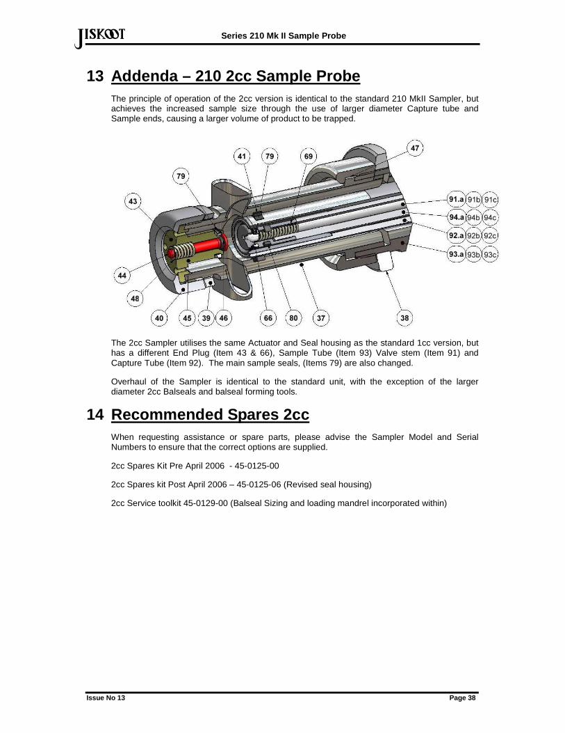
13 Addenda – 210 2cc Sample Probe The principle of operation of the 2cc version is identical to the standard 210 MkII Sampler, but achieves the increased sample size through the use of larger diameter Capture tube and Sample ends, causing a larger volume of product to be trapped.
The 2cc Sampler utilises the same Actuator and Seal housing as the standard 1cc version, but has a different End Plug (Item 43 & 66), Sample Tube (Item 93) Valve stem (Item 91) and Capture Tube (Item 92). The main sample seals, (Items 79) are also changed.
Overhaul of the Sampler is identical to the standard unit, with the exception of the larger diameter 2cc Balseals and balseal forming tools.
14 Recommended Spares 2cc When requesting assistance or spare parts, please advise the Sampler Model and Serial Numbers to ensure that the correct options are supplied.
2cc Spares Kit Pre April 2006 - 45-0125-00
2cc Spares kit Post April 2006 – 45-0125-06 (Revised seal housing)
2cc Service toolkit 45-0129-00 (Balseal Sizing and loading mandrel incorporated within)
Series 210 Mk II Sample Probe
Issue No 13 Page 39
def
15 Disclaimer Whilst Jiskoot Limited has taken every care in the preparation of this document, it cannot accept responsibility for printing errors or omissions and does not warrant that it is correct and comprehensive in every particular. Equipment supplied should always be operated by persons with an appropriate level of skill and training.
Jiskoot Limited shall not be liable for incidental or consequential damages resulting from the furnishing, performance or use of this material.
Jiskoot pursue a policy of continuous improvement, and information given herein may be updated without notice.
Further, this information is proprietary to Jiskoot Limited, and must not be disclosed to any third party except as may be required to operate the equipment supplied in accordance with the purposes for which it was sold by the persons properly licensed to operate it.
13 Graphic’s updated NMCG PW 26/03/2008
12 Revised to reflect redesigned seal housing and capture tube seal arrangements, 2cc addenda & assembly illustrations
NMCG PW 22/01/2008
11 Check Valve and Relief Valve settings clarified PW MAJ 15/02/2006
10 Added typical installation sketch and minimum diameter of pipeline tapping PW MAJ 25/01/2005
9 Generally revised, drawings added PW QI02/24 15/1/2002
8 Fully Revised PW MAJ 20/11/1998
Issue Revision History Issued Approved Date

Series 210 Mk II Sample Probe
Issue No 13 Page 40
def
Notes

Series 210 Mk II Sample Probe
Issue No 13 Page 41
def
Notes

Series 210 Mk II Sample Probe
Issue No 13 Page 42
def
Notes


www.jiskoot.com
def def Tunbridge Wells, Kent, TN1 2DJ, UK
Tel +44 (0)1892 518000, Fax +44 (0)1892 518100 Email: [email protected]
Houston, TX77014, USA
Tel +1-281-583 0583, Fax +1-281-583 0587
Email: [email protected]