Embed Size (px)
Citation preview
Operating Instruction IM/261Gx/Ax-EN Rev. 07
Models 261GS/GC/GG/GJ/GM/GN/GR Models 261AS/AC/AG/AJ/AM/AN/AR Pressure Transmitter
Measurement made easy

2 IM/261Gx/Ax-EN | 261Gx, 261Ax
Models 261GS/GC/GG/GJ/GM/GN/GR Models 261AS/AC/AG/AJ/AM/AN/AR Operating Instruction IM/261Gx/Ax-EN Rev. 07 Issue date: 09.2013 Translation of the original instruction
Manufacturer ABB Automation Products GmbH Process Automation Schillerstr. 72 32425 Minden Germany Tel: +49 551 905-534 Fax: +49 551 905-555 Customer service center Phone: +49 (0) 180 5 222 580 Fax: +49 (0) 621 381 931-29031 [email protected]

261Gx, 261Ax | IM/261Gx/Ax-EN 3
Change from one to two columns
Contents
1 Safety ............................................................................... 5 1.1 General information and notes for the reader ........ 5 1.2 Intended use ........................................................ 5 1.3 Improper use ....................................................... 5 1.4 Target groups and qualifications .......................... 5 1.5 Warranty provisions ............................................. 5 1.6 Plates and symbols .............................................. 6 1.6.1 Safety / warning symbols, note symbols .............. 6 1.7 Name plate .......................................................... 7 1.7.1 Compliance with Pressure Equipment Directive
(97/23/EC) ........................................................... 8 1.8 Transport safety instructions ................................ 8 1.9 Storage conditions ............................................... 8 1.10 Safety instructions for electrical installation ........... 8 1.11 Safety instructions for operation ........................... 8 1.12 Returning devices ................................................ 8 1.13 Integrated management system ........................... 9 1.14 Disposal .............................................................. 9 1.14.1 Information on WEEE Directive 2002/96/EC (Waste
Electrical and Electronic Equipment) ..................... 9 1.14.2 RoHS Directive 2002/95/EC ................................ 9
2 Use in potentially explosive atmospheres ................... 10 2.1 Explosion protection .......................................... 10 2.2 Type-examination certificate/Declaration of
conformity ......................................................... 10 2.3 Type of protection "intrinsic safety Ex i" .............. 10 2.4 Use in areas with combustible dust .................... 10 2.5 Category 3 (EPL Gc) with type of protection "nA" 10 2.6 Use of handheld terminal / PC ........................... 10
3 Function and System Design ........................................ 11 3.1 Principle of operation and construction .............. 11
4 Mounting ....................................................................... 13 4.1 Pressure transmitter ........................................... 13 4.2 Sealing and screw connections .......................... 14 4.3 Moisture ............................................................ 14 4.4 Measuring pipe .................................................. 15
5 Electrical connections ................................................... 16 5.1 Cable connection ............................................... 16 5.2 Electrical connection in the cable connection area
.......................................................................... 17 5.3 Electrical connection with plug ........................... 18 5.3.1 Assembly and connection of Han 8D (8U) socket
connector .......................................................... 19 5.4 Protective conductor/Grounding (optional) ......... 19 5.5 Communication setup ........................................ 19 5.6 Connecting cable ............................................... 20
6 Commissioning .............................................................. 21 6.1 General remarks ................................................ 21 6.2 Output signal ..................................................... 21
6.3 Write protection ................................................. 21 6.4 Adjusting lower range value / oblique sensor ...... 22 6.5 Installing/Removing the LCD indicator ................ 23 6.6 Pressure sensor ventilation ................................ 24
7 Configuration, parameterization ................................... 25 7.1.1 Standard configuration ...................................... 25 7.2 Configuration types ............................................ 25 7.3 Configuration using pushbutton on pressure
transmitter ......................................................... 25 7.3.1 General remarks ................................................ 25 7.3.2 Configuration ..................................................... 25 7.4 Configuration with the LCD indicator .................. 26 7.4.1 Menu navigation ................................................ 26 7.4.2 Process display ................................................. 27 7.4.3 Switching to the configuration level
(parameterization) .............................................. 27 7.4.4 Menu structure .................................................. 28 7.4.5 Parameter descriptions ...................................... 29 7.5 Configuration with the PC/laptop or handheld
terminal ............................................................. 32 7.6 Configuration with the graphical user interface
(DTM) ................................................................ 33 7.6.1 System requirements ......................................... 33 7.7 Parameter descriptions ...................................... 33
8 Ex relevant specifications ............................................. 35 8.1 Hazardous atmospheres .................................... 35 8.1.1 ATEX transmitter with type of protection "intrinsic
safety Ex ia/ib" in accordance with Directive 94/9/EC ............................................................ 35
8.1.2 IECEx transmitter with the following types of protection: "intrinsic safety ia", "non sparking nA" and "dust ignition protection by enclosure tb" .... 35
8.1.3 Factory Mutual (FM) ........................................... 36 8.1.4 Canadian Standards Association (CSA) .............. 36 8.1.5 NEPSI (China) .................................................... 36
9 Technical Data .............................................................. 37 9.1 Functional specifications .................................... 37 9.1.1 Measuring range limits and span limits ............... 37 9.1.2 Span limits ......................................................... 37 9.1.3 Zero suppression and elevation ......................... 37 9.1.4 Damping ............................................................ 37 9.1.5 Warm-up time ................................................... 37 9.1.6 Insulation resistance .......................................... 37 9.2 Operating limits .................................................. 38 9.2.1 Pressure limits ................................................... 38 9.2.2 Temperature limits °C (°F) .................................. 38 9.2.3 Limits for environmental effects .......................... 38 9.3 Measuring accuracy .......................................... 39 9.3.1 Reference conditions according to IEC 60770 ... 39 9.3.2 Dynamic response (according to IEC 61298-1) .. 39 9.3.3 Measuring error for setting cut-off point ............. 39 9.3.4 Ambient temperature ......................................... 39 9.3.5 Temperature coefficient (Tk) ............................... 39

4 IM/261Gx/Ax-EN | 261Gx, 261Ax
9.3.6 Power supply ..................................................... 39 9.3.7 Load .................................................................. 39 9.3.8 Electromagnetic fields ........................................ 40 9.3.9 Mounting position .............................................. 40 9.3.10 Long-term stability ............................................. 40 9.3.11 Vibration effect ................................................... 40 9.3.12 Total performance ............................................. 40 9.4 Technical specification ....................................... 41 9.4.1 Materials ............................................................ 41 9.4.2 Calibration ......................................................... 41 9.4.3 Optional extras .................................................. 41 9.4.4 Process connections ......................................... 41 9.4.5 Electrical connections ........................................ 42 9.4.6 Weight ............................................................... 42 9.4.7 Packaging ......................................................... 42 9.5 Mounting dimensions ......................................... 43 9.5.1 Standard version ............................................... 43 9.5.2 Version with the options “LCD indicator” and
“Harting Han plug” ............................................. 44 9.5.3 Transmitter with flush diaphragm ....................... 45 9.5.4 Version with ball valve connection ...................... 46 9.5.5 Mounting with angle bracket (optional) ............... 47
10 Maintenance / Repair .................................................... 48 10.1 Removal ............................................................ 48
11 Appendix ....................................................................... 49 11.1 Approvals and certifications ............................... 49

261Gx, 261Ax | IM/261Gx/Ax-EN 5
1 Safety
1.1 General information and notes for the reader You must read these instructions carefully prior to installing and commissioning the device. These instructions are an important part of the product and must be kept for future reference. These instructions are intended as an overview and do not contain detailed information on all designs for this product or every possible aspect of installation, operation and maintenance. For additional information or if specific problems occur that are not discussed in these instructions, contact the manufacturer. The content of these instructions is neither part of any previous or existing agreement, promise or legal relationship nor is it intended to change the same. This product is built based on state-of-the-art technology and is operationally safe. It has been tested and left the factory in perfect working order from a safety perspective. The information in the manual must be observed and followed in order to maintain this state throughout the period of operation. Modifications and repairs to the product may only be performed if expressly permitted by these instructions. Only by observing all of the safety instructions and all safety / warning symbols in these instructions can optimum protection of both personnel and the environment, as well as safe and fault-free operation of the device, be ensured. Information and symbols directly on the product must be observed. They may not be removed and must be fully legible at all times. 1.2 Intended use 261A pressure transmitters measure absolute pressure and 261G pressure transmitters gauge pressure or the level of gases, vapors and liquids. For information on measuring ranges and permissible overload, refer to the section "Specifications". Using these products as intended involves observing the following points: — Read and follow the instructions in this manual. — Observe the technical limit values (refer to the section
"Specifications"). — Use only approved liquids for measurement (refer to the
section “Permissible measuring agents”).
1.3 Improper use The following are considered to be instances of improper use of the device: — As a climbing aid, e.g., for mounting purposes. — As a support for external loads, e.g., as a support for
piping, etc. — Adding material, e.g., by painting over the name plate or
welding/soldering on parts. — Removing material, e.g., by spot drilling the housing. 1.4 Target groups and qualifications Installation, commissioning and maintenance of the product may only be performed by trained specialist personnel who have been authorized by the plant operator to do so. The specialist personnel must have read and understood the manual and comply with its instructions. The operators must strictly observe the applicable national regulations with regards to installation, function tests, repairs, and maintenance of electrical products. 1.5 Warranty provisions Using the device in a manner that does not fall within the scope of its intended use, disregarding this manual, using underqualified personnel, or making unauthorized alterations releases the manufacturer from liability for any resulting damage. This renders the manufacturer's warranty null and void.

6 IM/261Gx/Ax-EN | 261Gx, 261Ax
1.6 Plates and symbols 1.6.1 Safety / warning symbols, note symbols
DANGER – Serious damage to health / risk to life! This symbol in conjunction with the signal word “Danger“ indicates an imminent danger. Failure to observe this safety information will result in death or severe injury.
DANGER – Serious damage to health / risk to life! This symbol in conjunction with the signal word “Danger” indicates an imminent electrical hazard. Failure to observe this safety information will result in death or severe injury.
WARNING – Body injury! This symbol in conjunction with the signal word “Warning” indicates a possibly dangerous situation. Failure to observe this safety information may result in death or severe injury.
WARNING – Body injury! This symbol in conjunction with the signal word “Warning” indicates a potential electrical hazard. Failure to observe this safety information may result in death or severe injury.
CAUTION – Minor injury! This symbol in conjunction with the signal word “Caution“ indicates a possibly dangerous situation. Failure to observe this safety information may result in minor or moderate injury. This may also be used for property damage warnings.
ATTENTION – Property damage! The symbol indicates a potentially damaging situation. Failure to observe this safety information may result in damage to or destruction of the product and / or other system components.
IMPORTANT (NOTE) This symbol indicates operator tips, particularly useful information, or important information about the product or its further uses. It does not indicate a dangerous or damaging situation.

261Gx, 261Ax | IM/261Gx/Ax-EN 7
1.7 Name plate
Fig. 1: Name plate for pressure transmitter model 261xx 1 Device type / Order code | 2 Options – additional information on the order code | 3 Device serial number (factory no.) | 4 Year of manufacture | 5 Identification code with reference to the Pressure Equipment Directive (SEP or 1 G) | 6 Power supply | 7 Output signal | 8 Materials that come into contact with the medium | 9 Measuring range lower limit to measuring range upper limit (LRL to URL) | 10 Measuring range, set to … | 11 HART output (process variable) | 12 Measuring point tag (max. 32 characters) | 13 "SIL2" identification code (optional) | 14 Permissible pressure | 15 Degree of protection | 16 Software version | 17 Filling fluid, if present | 18 Minimum measuring span
Fig. 2: Additional name plate for devices intended for use in
explosion risk areas or for devices with direct mount or remote seals (optional)
1 Serial number (factory no.) | 2 Type of protection | 3 Type of protection (continued) | 4 Number of the EC-type-examination certificate | 5 Order code for direct mount seal | 6 Type of seal, nominal diameter, max. pressure, temperature limits, sealing surface, material, filling fluid | 7 Identification number of the notified body according to ATEX (optional) | 8 Symbol: "Notice". Observe the specifications in the operating instructions and type-examination certificate.
IMPORTANT (NOTE) For information on the individual letters/numbers that make up the order code, please refer to the order confirmation or associated data sheet. For information about labeling in accordance with the Pressure Equipment Directive, please observe the information in "Compliance with Pressure Equipment Directive".

8 IM/261Gx/Ax-EN | 261Gx, 261Ax
1.7.1 Compliance with Pressure Equipment Directive (97/23/EC)
Devices with PS > 200 bar (20 MPa) Devices with a permissible pressure of PS > 200 bar (20 MPa) have been tested for conformity by the Technical Supervisory Association TÜV NORD (0045) in accordance with module H and can be used for fluids of group 1 (PED: 1G). The name plate bears the following identification codes:
Fig. 3: Identification codes according to Pressure Equipment
Directive (example) 1 PED: 1G | 2 Identification number of the notified body according to the Pressure Equipment Directive | 3 "SIL 2" identification code (optional) Devices with PS ≤ 200 bar (20 MPa) Devices with a permissible pressure PS ≤ 200 bar (20 MPa) conform to sec. 3 para. (3) and have not been tested for conformity. The devices have been constructed and manufactured according to sound engineering practice (SEP). The CE marking on the device does not refer to the Pressure Equipment Directive. The name plate then contains the following identification codes: PED: SEP. 1.8 Transport safety instructions Observe the following instructions: — Do not expose the device to moisture during transport.
Pack the device accordingly. — Pack the device so that it is protected against vibrations
during transport, e.g., by using air-cushioned packaging. Prior to installation, check the devices for possible damage that may have occurred as a result of improper transport. Details of any damage that has occurred in transit must be recorded on the transport documents. All claims for damages must be submitted to the shipper without delay and before installation.
1.9 Storage conditions — The device must be stored in dry and dust-free conditions.
Always keep the device in its original package during storage / transport.
— Observe the permissible ambient conditions for transport and storage according to the section "Specifications".
— In principle, the devices may be stored for an unlimited period. However, the warranty conditions stipulated in the order confirmation of the supplier apply.
1.10 Safety instructions for electrical installation The electrical connection may only be established by authorized specialist personnel and in accordance with the connection diagrams. The electrical connection information in the manual must be observed; otherwise, the type of electrical protection may be adversely affected. Ground the measurement system according to requirements. 1.11 Safety instructions for operation Before switching on the device, make sure that your installation complies with the environmental conditions listed in the chapter "Specifications" or on the data sheet. If there is a chance that safe operation is no longer possible, take the device out of operation and secure it against unintended startup. 1.12 Returning devices Use the original packaging or a secure transport container of an appropriate type if you need to return the device for repair or recalibration purposes. Fill out the return form (see the Appendix) and include this with the device. According to the EU Directive governing hazardous materials, the owner of hazardous waste is responsible for its disposal or must observe the following regulations for shipping purposes: All devices delivered to ABB Automation Products GmbH must be free from any hazardous materials (acids, alkalis, solvents, etc.).
Please contact Customer Center Service acc. to page 2 for nearest service location.

261Gx, 261Ax | IM/261Gx/Ax-EN 9
1.13 Integrated management system ABB Automation Products GmbH operates an integrated management system, consisting of: — Quality management system to ISO 9001:2008 — Environmental management system to ISO 14001:2004 — Occupational health and safety management system to
BS OHSAS 18001:2007 and — Data and information protection management system Environmental awareness is an important part of our company policy. Our products and solutions are intended to have minimum impact on the environment and on people during manufacturing, storage, transport, use, and disposal. This includes the environmentally-friendly use of natural resources. We conduct an open dialog with the public through our publications. 1.14 Disposal This product is manufactured from materials that can be recycled by specialist recycling companies.
1.14.1 Information on WEEE Directive 2002/96/EC (Waste Electrical and Electronic Equipment)
This product is not subject to WEEE Directive 2002/96/EC or relevant national laws (e.g., ElektroG in Germany). The product must be disposed of at a specialist recycling facility. Do not use municipal garbage collection points. According to the WEEE Directive 2002/96/EC, only products used in private applications may be disposed of at municipal garbage collection points. Proper disposal prevents negative effects on people and the environment, and supports the reuse of valuable raw materials. If it is not possible to dispose of old equipment properly, ABB Service can accept and dispose of returns for a fee. 1.14.2 RoHS Directive 2002/95/EC With the Electrical and Electronic Equipment Act (ElektroG) in Germany, the European Directives 2002/96/EC (WEEE) and 2002/95/EC (RoHS) are translated into national law. ElektroG defines the products that are subject to regulated collection and disposal or reuse in the event of disposal or at the end of their service life. ElektroG also prohibits the marketing of electrical and electronic equipment that contains certain amounts of lead, cadmium, mercury, hexavalent chromium, polybrominated biphenyls (PBB), and polybrominated diphenyl ethers (PBDE) (also known as hazardous substances with restricted uses). The products provided by ABB Automation Products GmbH do not fall within the current scope of regulations on hazardous substances with restricted uses or the directive on waste electrical and electronic equipment according to ElektroG. If the necessary components are available on the market at the right time, in the future these substances will no longer be used in new product development.

10 IM/261Gx/Ax-EN | 261Gx, 261Ax
2 Use in potentially explosive atmospheres
2.1 Explosion protection The device complies with the explosion-protection requirements of Directive 94/9/EC (ATEX). When installing explosion-proof transmitters (e.g., electrical connection, ground/PE, etc.), observe national regulations, DIN/VDE standards and explosion-protection directives. The certified explosion-proof designation for the transmitter is provided on the name plate. 2.2 Type-examination certificate/Declaration of
conformity For explosion-proof models, the EC-type-examination certificate or declaration of conformity is included with these operating instructions. 2.3 Type of protection "intrinsic safety Ex i" Only intrinsically safe devices may be installed in the transmitter signal circuit. The signal circuit can be interrupted while the transmitter is in operation (e.g., clamping/unclamping signal lines). The housing may be opened during operation. Transmitters with and without remote seals and featuring type of protection "intrinsic safety Ex i" may be directly integrated into the partition separating Zone 0 and Zone 1 (sensor diaphragm in Zone 0, transmitter in Zone1), provided that the power is supplied via an intrinsically safe circuit with type of protection "Ex ia". 2.4 Use in areas with combustible dust Installation must be performed in accordance with EN 61241-14:2004. Transmitters can only be connected using cable glands certified in accordance with Directive 94/9/EC (ATEX). The cable gland must conform to IP 67 degree of protection. The smoldering temperature of the dust must be at least 75 K above the maximum surface temperature of the transmitter. The maximum surface temperature is 95 °C (203 °F) and is obtained by adding together the maximum ambient temperature (85 °C (185 °F)) and the maximum self-heating (10 K).
WARNING! Risk of explosion! When using remote seals with an anti-stick coating, be aware of the risk of electrostatic discharge (with consideration given to the filling material and transport speed).
2.5 Category 3 (EPL Gc) with type of protection "nA" The transmitter must be connected using a certified cable gland (not included in scope of delivery). The cable gland must satisfy the requirements of type of protection "increased safety Ex e" in accordance with Directive 94/9/EC (ATEX). Additionally, the conditions stipulated in the type-examination certificate for the cable gland must be observed.
WARNING! Risk of explosion! Opening the housing during operation (with the supply voltage switched on) is not permitted. Opening the cover presents a risk of spark formation and, therefore, explosion. Only open the housing when the supply voltage is switched off.
2.6 Use of handheld terminal / PC If a handheld terminal or a PC is being used for communication / configuration / parameterization in a potentially explosive atmosphere with type of protection "intrinsic safety", the devices used must be certified accordingly. This applies even if the device is only connected for a short period of time. This proof of "intrinsic safety" must be supplied in addition to the transmitter.
WARNING! Risk of explosion! The handheld terminal battery must not be replaced in a potentially explosive atmosphere. Replacing the battery presents a risk of spark formation and, therefore, explosion. The battery may only be replaced outside of the potentially explosive atmosphere.

261Gx, 261Ax | IM/261Gx/Ax-EN 11
3 Function and System Design
Digital pressure transmitters are communication-ready field devices with microprocessor-controlled electronics. For bidirectional communication, an FSK signal is superimposed on the 4 … 20 mA output signal via the HART protocol. The graphic user interface (DTM) can be used to configure, poll, and test the pressure transmitter on a PC. Handheld terminals also support communication. For “local” operation, a button is available on the system electronics for setting the lower and upper range values. In combination with an optionally installed LCD indicator, a complete external configuration and parameter setting of the transmitter can be performed via the four local pushbutton controls. The sturdy electronics housing is made of stainless steel and is resistant to aggressive atmospheres. The process connection is also made of stainless steel or Hastelloy C. The name plate contains information about the specific pressure transmitter version (see section "Safety / Name plates").
IMPORTANT (NOTE) For explosion-proof transmitters, the explosion protection type and, in case of attached pressure sensors, the corresponding pressure sensor type is specified on a separate plate.
In addition, a tag indicating the measuring points may be attached (as an option).
3.1 Principle of operation and construction The transmitter has a compact design and comprises the pressure measuring cell and electronic unit with pushbutton control. Depending on the measuring range and measured variable, either a ceramic pressure sensor or a silicon pressure sensor is used. Ceramic pressure sensor In case of ceramic pressure sensors, the applied process pressure (pe/pabs) is transferred directly to the measuring diaphragm. Even a very slight deflection of the measuring diaphragm will change the internal output voltage of the pick-up system. Silicon pressure sensor In case of silicon pressure sensors, the pressure is transferred via the separation diaphragm and the filling fluid to the measuring diaphragm. The resistance values of the four piezo resistors doped in the measuring diaphragm will change. This pressure-proportional, internal output voltage is converted via the electronic unit into a scaled electrical signal. Depending on the model, the transmitter is connected to the process by means of a spigot G ½ B (DIN EN 837-1), ½-14 NPT male or female thread, flush diaphragm with special thread G ½" for, e.g., ball valve connection or different pressure sensors. The pressure transmitter operates on the basis of two-wire technology. The same wires are used for the operating voltage (device-specific, see “Specifications”) and the scaled output signal. The electrical connection is established via a cable entry or plug.

12 IM/261Gx/Ax-EN | 261Gx, 261Ax
Fig. 4: 261G transmitter for gauge pressure and fill level (example) 1 Process connection | 2 Separation diaphragm | 3 Filling fluid | 4 Measuring cell | 5 Pressure sensor | 6 Pushbutton for lower / upper range values | 7 Microprocessor-controlled electronics | 8 Output / Supply power
Fig. 5: 261A transmitter for absolute pressure (example) 1 Process connection | 2 O-ring | 3 Measuring capsule | 4 Measuring equipment | 5 Pushbutton for lower / upper range values | 6 Microprocessor-controlled electronics | 7 Output / Supply power | 8 Measuring diaphragm
To measure the output signal and to configure or calibrate the pressure transmitter, an ammeter must be connected directly to the output circuit. The lower and upper range values can be set via a pushbutton on the electronic unit. An optional fastener is available for attaching a stainless steel tag so that the measuring points can be indicated. The transmitter may also be equipped with an LCD indicator that can be read from above (optional, can be retrofitted). With the aid of this LCD indicator, the most important transmitter functions or data can be fully configured using the “local” control unit (four pushbuttons on the indicator) (see “Configuration”).
261Gx, 261Ax | IM/261Gx/Ax-EN 13
4 Mounting
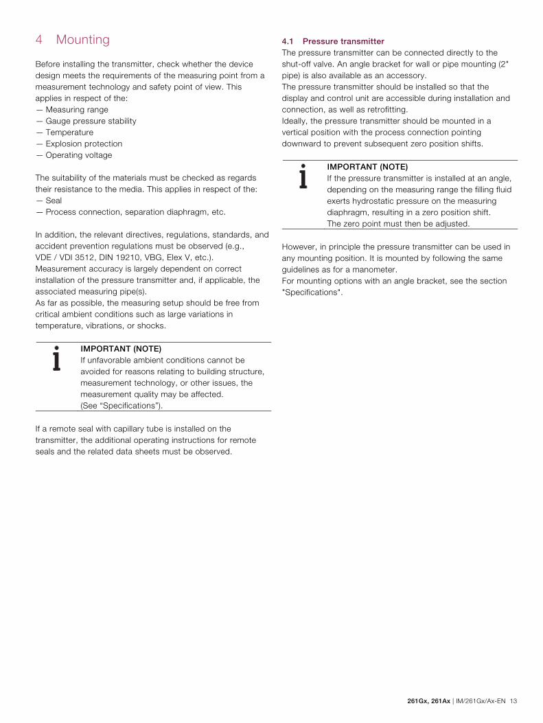
Before installing the transmitter, check whether the device design meets the requirements of the measuring point from a measurement technology and safety point of view. This applies in respect of the: — Measuring range — Gauge pressure stability — Temperature — Explosion protection — Operating voltage The suitability of the materials must be checked as regards their resistance to the media. This applies in respect of the: — Seal — Process connection, separation diaphragm, etc. In addition, the relevant directives, regulations, standards, and accident prevention regulations must be observed (e.g., VDE / VDI 3512, DIN 19210, VBG, Elex V, etc.). Measurement accuracy is largely dependent on correct installation of the pressure transmitter and, if applicable, the associated measuring pipe(s). As far as possible, the measuring setup should be free from critical ambient conditions such as large variations in temperature, vibrations, or shocks.
IMPORTANT (NOTE) If unfavorable ambient conditions cannot be avoided for reasons relating to building structure, measurement technology, or other issues, the measurement quality may be affected. (See “Specifications”).
If a remote seal with capillary tube is installed on the transmitter, the additional operating instructions for remote seals and the related data sheets must be observed.
4.1 Pressure transmitter The pressure transmitter can be connected directly to the shut-off valve. An angle bracket for wall or pipe mounting (2" pipe) is also available as an accessory. The pressure transmitter should be installed so that the display and control unit are accessible during installation and connection, as well as retrofitting. Ideally, the pressure transmitter should be mounted in a vertical position with the process connection pointing downward to prevent subsequent zero position shifts.
IMPORTANT (NOTE) If the pressure transmitter is installed at an angle, depending on the measuring range the filling fluid exerts hydrostatic pressure on the measuring diaphragm, resulting in a zero position shift. The zero point must then be adjusted.
However, in principle the pressure transmitter can be used in any mounting position. It is mounted by following the same guidelines as for a manometer. For mounting options with an angle bracket, see the section "Specifications".

14 IM/261Gx/Ax-EN | 261Gx, 261Ax
4.2 Sealing and screw connections Connecting G ½ B spigot: For sealing, a flat gasket must be used in accordance with DIN EN 837-1. NPT threaded connection: Seal the threads with PTFE or another approved resistant sealant. Process connection with flush diaphragm: Prior to mounting the device, install a welded connection or tapped hole according to relevant soldering standards (for process connection and welded connection dimensions, see “Specifications”). Process connection for ball valve: An appropriate ball valve connection or weld-in sleeve is required for mounting purposes. In this case, the seal is formed by a cone at the outer end of the process connection (metal/metal). For information on the weld-in sleeve, see “Specifications”.
4.3 Moisture Use suitable cables and tighten cable glands securely. The transmitter can also be protected against the ingress of moisture by routing the connecting cable downward before securing it. This allows rain and condensation to drip down. This is especially important for installation in outdoor areas and rooms that are exposed to moisture (e.g., due to cleaning processes) or on cooled or heated tanks.
Fig. 6: Steps for preventing the ingress of moisture

261Gx, 261Ax | IM/261Gx/Ax-EN 15
4.4 Measuring pipe In order for the pipes to be laid correctly, the following points must be observed: — Keep the measuring pipe as short as possible and avoid
sharp bends. — Lay the measuring pipe in such a way that no deposits can
accumulate in it. Gradients should not be less than approx. 8 % (ascending or descending).
— The measuring pipe should be blown through with compressed air or, better yet, flushed through with the measuring medium before connection.
— Completely depressurize the measuring pipe if the medium is a fluid.
— Lay the measuring pipe in such a way that gas bubbles (when measuring fluids) or condensate (when measuring gases) can flow back into the process line.
— When measuring steam, lay the measuring pipe in such a way that hot steam cannot flow back into the process connection (water trap, e.g., a water trap pipe that is filled with water before installation).
— Check the tightness of the connection.

16 IM/261Gx/Ax-EN | 261Gx, 261Ax
5 Electrical connections
WARNING – Electrical dangers! Observe the applicable regulations governing electrical installation. Connections must only be established in a dead-voltage state. The transmitter has no switch-off elements. Therefore, overcurrent protective devices, lightning protection, or voltage disconnection options must be provided at the plant. Check that the existing operating voltage corresponds to the voltage indicated on the name plate. The same lines are used for both the power supply and output signal.
5.1 Cable connection Depending on the model supplied, the electrical connection is established via cable gland M16x1.5 (for diameters of 5 to 10 mm) or M20x1.5 (for diameters of 6 to 11 mm), a threaded bore for cable gland 1/2-14 NPT, or via the Han 8U plug, i.e., via the miniature plug connector M12 x 1 (see also "Technical specification / Electrical connections"). The screw terminals are suitable for wiring cross-sections up to 1.5 mm². It is recommended that you strip approx. 30 … 35 mm (1.18 … 1.38 inch) off the cable jacket.
Fig. 7: Stripped connecting cable
IMPORTANT (NOTE) After a period of several weeks, removing the screws in the housing cover requires increased force. This is not caused by the threads, but instead is due solely to the type of seal.

261Gx, 261Ax | IM/261Gx/Ax-EN 17
Change from two to one column
5.2 Electrical connection in the cable connection area
Fig. 8 1 Pushbutton for lower/upper range values | 2 + Signal screw terminals for leads with cross-section of 0.5 … 1.5 mm2 | 3 - Signal screw terminals for leads with a cross-section of 0.5 … 1.5 mm2 | 4 Grounding / equipotential bonding terminal (optional) | 5 Cable entry | 6 Line load | 7 Grounding | 8 Handheld terminal | 9 Resistor (min. 250 Ω) | 10 Power supply / power supply unit | 11 Optional ground | 12 Receiver
application Permissible voltage range of power supply
Transmitter operated outside the potentially explosive atmosphere. 11 … 42 V
Transmitter operated inside the potentially explosive atmosphere. 11 … max. 30 V (intrinsically safe)
WARNING! Risk of explosion! If, when using transmitters with type of protection "intrinsic safety", an ammeter is connected to the output circuit or a modem is connected in parallel while there is a risk of explosion, the sums of the capacitances and inductances of all circuits, including the transmitter (see EC-type-examination certificate) must be equal to or less than the permissible capacitances and inductances of the intrinsically safe signal circuit (see EC-type-examination certificate for the power supply unit). Only passive or explosion-proof devices or indicators may be connected.
18 IM/261Gx/Ax-EN | 261Gx, 261Ax
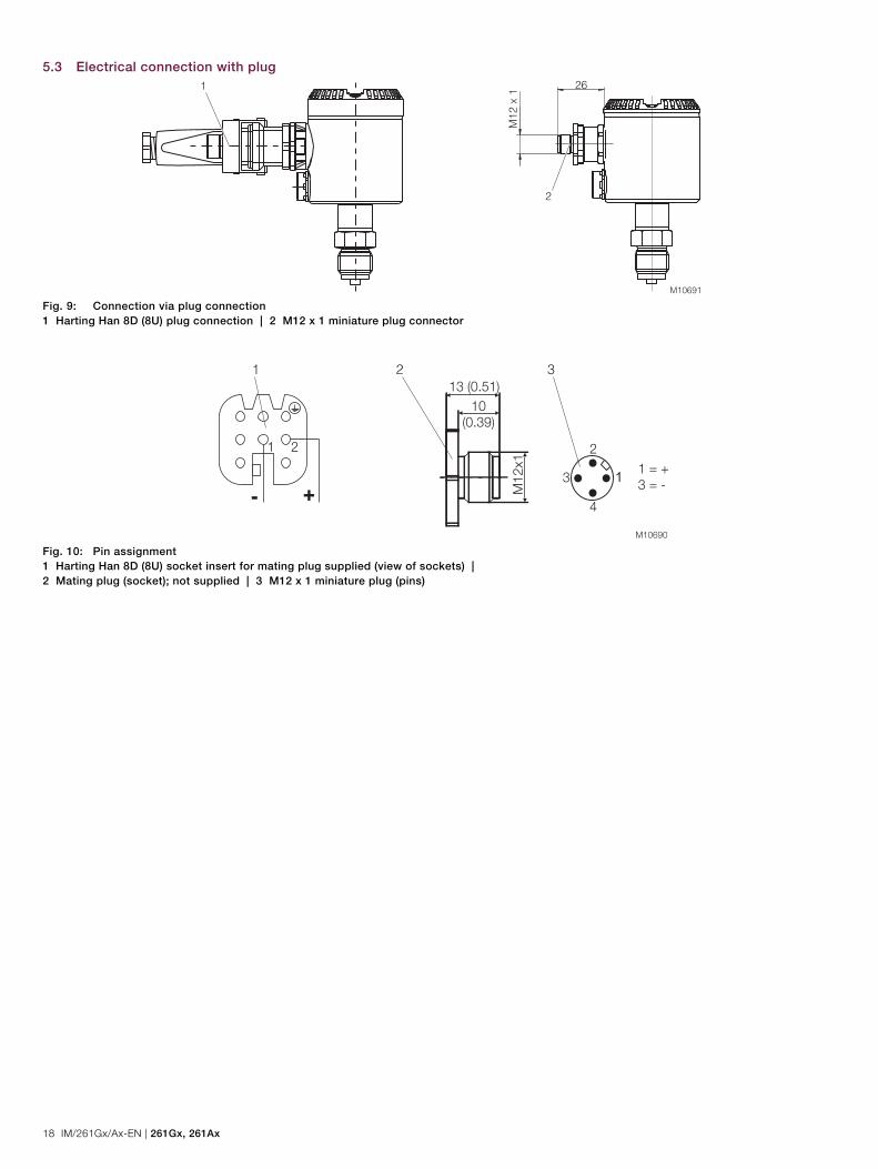
5.3 Electrical connection with plug
M10691
M12
x 1
261
2
Fig. 9: Connection via plug connection 1 Harting Han 8D (8U) plug connection | 2 M12 x 1 miniature plug connector
Fig. 10: Pin assignment 1 Harting Han 8D (8U) socket insert for mating plug supplied (view of sockets) | 2 Mating plug (socket); not supplied | 3 M12 x 1 miniature plug (pins)

261Gx, 261Ax | IM/261Gx/Ax-EN 19
Change from one to two columns
5.3.1 Assembly and connection of Han 8D (8U) socket connector
The socket connector for connecting the cable is supplied unassembled as an accessory for the transmitter.
IMPORTANT (NOTE) Please observe the specifications for the electrical connection that have been supplied with the connector.
Assembly is depicted in the figure below.
Fig. 11: Assembling the socket connector 1 Socket | 2 Contact | 3 Socket shell | 4 Gasket (can be cut) | 5 Thrust collar | 6 PG 11 pressure screw | 7 Cable (diameter 5 … 11 mm (0.20 ... 0.43 inch)) 1. The contacts are crimped or soldered onto the cable ends
(wire cross-section of 0.75 … 1 mm2 (AWG 18 … AWG 17)), from which approx. 1.5 … 2 cm (0.59 … 0.79 inch) of the sleeve and approx. 8 mm (0.32 inch) of the insulation have been stripped; they are then inserted into the socket from the rear.
2. Slide the pressure screw, thrust collar, gasket, and socket shell onto the cable in the order indicated before assembly (you may have to adjust the gasket to fit the cable diameter).
5.4 Protective conductor/Grounding (optional) A terminal is available on the outside of the housing for grounding (PE) the transmitter.
5.5 Communication setup The transmitter can be operated via a modem, using a PC or laptop. The modem can be connected to the transmitter in parallel at any point in the signal circuit. Communication between transmitter and modem occurs via AC signals that are superimposed on the analog 4 ... 20 mA output signal. This modulation occurs without averaging and does not, therefore, affect the measuring signal. Communication between transmitter and PC or laptop is only possible if the signal circuit is set up as shown in the following figure, “Communication mode: Point-to-point”. The resistance between the connecting point for the FSK modem and the power supply must be at least 250 Ω (including internal resistance of the power supply unit). If this value is not achieved within the context of normal installation, an additional resistor must be used. The ABB Contrans I supply modules with HART communication already have a factory-installed, additional resistor. Some of these modules offer the option of communicating directly over the supply module in the operating mode "FSK bus". Power can be supplied by power supply units, batteries, or power supplies; these must be designed to ensure that the operating voltage UB of the transmitter always remains between DC 11 V and 42 V (30 V for "Ex i"). In addition, the maximum current of 20 … 23.6 mA resulting from overranging must be considered, depending on the corresponding parameterization. This yields the minimum value for US. If additional signal receivers (e.g., indicators) are looped into the signal circuit, their resistance must also be considered.

20 IM/261Gx/Ax-EN | 261Gx, 261Ax
Change from two to one column
M10693
p
I + FSKA
UB US
+
+ +
– –#
R
2600T
RS 232C
4
1 2 3
Fig. 12: "Point-to-point" communication mode 1 Pressure transmitter | 2 Possible connecting points for a modem between A and B | 3 Power supply unit | 4 FSK modem
M10694
RS 232C
p
I + FSKA
UB US
+
+ +
#
R
2600T
4 & 20 mA
p
I + FSKA
UB US
+
+ +
#
R
2600T
4 & 20 mA
1
1
3
2
2
Fig. 13: "FSK bus" communication mode 1 FSK bus | 2 Supply module with HART isolation | 3 FSK modem
5.6 Connecting cable Communication between the transmitter and PC or laptop is only possible if the cabling meets the following requirements: The minimum wire diameter depends on the line length. Line lengths up to 1,500 m: 0.51 mm Line lengths above 1,500 m: 0.81 mm The maximum line length is limited. Dual-core cable: 3,000 m Multi-core cable: 1,500 m
The actual possible line length of the electrical circuit depends on the total capacitance and total line resistance, and can be estimated using the following formula:
CC
RxCxL f 1000
61065
L = Line length in m R = Total line resistance in Ω (ohms) C = Line capacitance in pF/m Cf = Capacitance of the devices located in the circuit in pF Avoid routing cables with other electrical cables (with inductive load, etc.) or near large electrical equipment.

261Gx, 261Ax | IM/261Gx/Ax-EN 21
6 Commissioning
6.1 General remarks Once the pressure transmitter has been installed, it is put into operation by switching on the operating voltage. Check the following before switching on the operating voltage: — Process connections — Electrical connection — The measuring pipe and measuring chamber of the
measuring equipment must be completely filled with the measuring medium.
The transmitter can then be put into operation. To do this, the shut-off valves must be actuated in the following order (in the default setting, all valves are closed): 1. Open the discharge shut-off valve, if present. 2. Open the shut-off valve. To put the transmitter out of operation, carry out the steps in reverse order.
IMPORTANT (NOTE) In the case of pressure transmitters for absolute pressure that feature a ceramic pressure sensor and measuring ranges of ≤ 40 kPa absolute, please be aware that the pressure measuring cell will have been overloaded by the atmospheric pressure due to the long periods of transport and storage involved. For this reason, you will need to allow a starting time of approx. 3 hours after commissioning, until the sensor has stabilized to such an extent that the specified accuracy can be maintained.
If, when using transmitters with type of protection "intrinsic safety", an ammeter is connected to the output circuit or a modem is connected in parallel while there is a risk of explosion, the sums of the capacitances and inductances of all circuits, including the transmitter (see EC-type-examination certificate) must be equal to or less than the permissible capacitances and inductances of the intrinsically safe signal circuit (see EC-type-examination certificate for the power supply unit). Only passive or explosion-proof devices or indicators may be connected. If the output signal stabilizes only slowly, it is likely that a large damping time constant has been set on the transmitter.
6.2 Output signal If the applied pressure is within the values indicated on the name plate, the output current ranges between 4 und 20 mA. If the pressure applied falls outside the set range, the output current will be between 3.5 mA and 4 mA if the range is undershot or between 20 mA and 23.6 mA if the range is overshot (depending on the respective configuration). Standard setting for normal operation 3.8 mA / 20.5 mA A current that is < 4 mA or > 20 mA may also indicate that the microprocessor has detected an internal error. Standard setting for error detection 21 mA The graphical user interface (DTM) can be used to diagnose the error.
IMPORTANT (NOTE) A brief interruption in the power supply results in initialization of the electronics (program restarts).
6.3 Write protection Write protection prevents the configuration data from being overwritten by unauthorized users. If write protection is enabled, the "Lower Range Value / Upper Range Value” pushbutton will be disabled. It is still possible to read out the configuration data via optional LCD indicator, handheld terminal or the graphical user interface (DTM). Write protection can be disabled via the graphical user interface (DTM), a HART handheld terminal, or an optional LCD indicator (see “Write protection” under “Configuration”).
22 IM/261Gx/Ax-EN | 261Gx, 261Ax
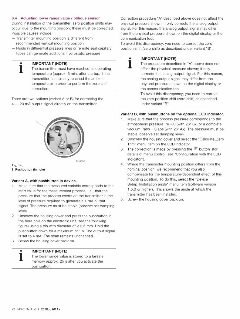
6.4 Adjusting lower range value / oblique sensor During installation of the transmitter, zero position shifts may occur due to the mounting position; these must be corrected. Possible causes include: — Transmitter mounting position is different from
recommended vertical mounting position — Fluids in differential pressure lines or remote seal capillary
tubes can generate additional hydrostatic pressure
IMPORTANT (NOTE) The transmitter must have reached its operating temperature (approx. 5 min. after startup, if the transmitter has already reached the ambient temperature) in order to perform the zero shift correction.
There are two options (variant A or B) for correcting the 4 … 20 mA output signal directly on the transmitter.
M10696
1
Fig. 14: 1 Pushbutton (in hole)
Variant A, with pushbutton in device. 1. Make sure that the measured variable corresponds to the
start value for the measurement process, i.e., that the pressure that the process exerts on the transmitter is the level of pressure required to generate a 4 mA output signal. The pressure must be stable (observe set damping level).
2. Unscrew the housing cover and press the pushbutton in the bore hole on the electronic unit (see the following figure) using a pin with diameter of ≤ 2.5 mm. Hold the pushbutton down for a maximum of 1 s. The output signal is set to 4 mA. The span remains unchanged.
3. Screw the housing cover back on.
IMPORTANT (NOTE) The lower range value is stored to a failsafe memory approx. 25 s after you activate the pushbutton.
Correction procedure "A" described above does not affect the physical pressure shown; it only corrects the analog output signal. For this reason, the analog output signal may differ from the physical pressure shown on the digital display or the communication tool. To avoid this discrepancy, you need to correct the zero position shift (zero shift) as described under variant "B".
IMPORTANT (NOTE) The procedure described in "A" above does not affect the physical pressure shown; it only corrects the analog output signal. For this reason, the analog output signal may differ from the physical pressure shown on the digital display or the communication tool. To avoid this discrepancy, you need to correct the zero position shift (zero shift) as described under variant "B".
Variant B, with pushbuttons on the optional LCD indicator. 1. Make sure that the process pressure corresponds to the
atmospheric pressure Pe = 0 (with 261Gx) or a complete vacuum Pabs = 0 abs (with 261Ax). The pressure must be stable (observe set damping level).
2. Unscrew the housing cover and select the "Calibrate_Zero Trim” menu item on the LCD indicator.
3. The correction is made by pressing the button (for details of menu control, see "Configuration with the LCD indicator").
4. Where the transmitter mounting position differs from the nominal position, we recommend that you also compensate for the temperature-dependent effect of this mounting position. To do this, select the "Device Setup_Installation angle" menu item (software version 1.5.0 or higher). This shows the angle at which the transmitter has been installed.
5. Screw the housing cover back on.
261Gx, 261Ax | IM/261Gx/Ax-EN 23
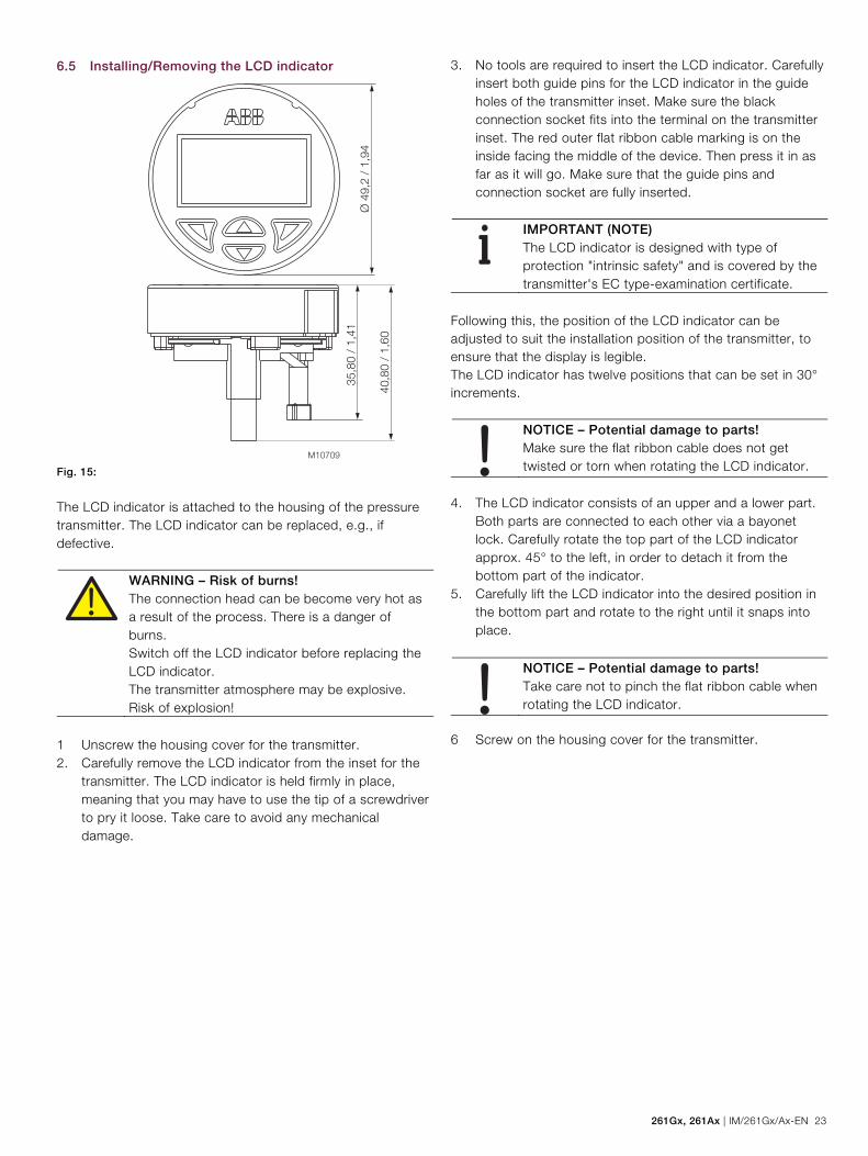
6.5 Installing/Removing the LCD indicator
Fig. 15:
The LCD indicator is attached to the housing of the pressure transmitter. The LCD indicator can be replaced, e.g., if defective.
WARNING – Risk of burns! The connection head can be become very hot as a result of the process. There is a danger of burns. Switch off the LCD indicator before replacing the LCD indicator. The transmitter atmosphere may be explosive. Risk of explosion!
1 Unscrew the housing cover for the transmitter. 2. Carefully remove the LCD indicator from the inset for the
transmitter. The LCD indicator is held firmly in place, meaning that you may have to use the tip of a screwdriver to pry it loose. Take care to avoid any mechanical damage.
3. No tools are required to insert the LCD indicator. Carefully insert both guide pins for the LCD indicator in the guide holes of the transmitter inset. Make sure the black connection socket fits into the terminal on the transmitter inset. The red outer flat ribbon cable marking is on the inside facing the middle of the device. Then press it in as far as it will go. Make sure that the guide pins and connection socket are fully inserted.
IMPORTANT (NOTE) The LCD indicator is designed with type of protection "intrinsic safety" and is covered by the transmitter's EC type-examination certificate.
Following this, the position of the LCD indicator can be adjusted to suit the installation position of the transmitter, to ensure that the display is legible. The LCD indicator has twelve positions that can be set in 30° increments.
NOTICE – Potential damage to parts! Make sure the flat ribbon cable does not get twisted or torn when rotating the LCD indicator.
4. The LCD indicator consists of an upper and a lower part.
Both parts are connected to each other via a bayonet lock. Carefully rotate the top part of the LCD indicator approx. 45° to the left, in order to detach it from the bottom part of the indicator.
5. Carefully lift the LCD indicator into the desired position in the bottom part and rotate to the right until it snaps into place.
NOTICE – Potential damage to parts! Take care not to pinch the flat ribbon cable when rotating the LCD indicator.
6 Screw on the housing cover for the transmitter.

24 IM/261Gx/Ax-EN | 261Gx, 261Ax
6.6 Pressure sensor ventilation
M10695
1
Fig. 16: Ventilation unit
For technical reasons, you must apply atmospheric pressure to the reference side of the pressure sensor. A special ventilation unit (1) is screwed into the electronic housing from the outside and is equipped with a PTFE filter on the inside. Make sure that the ventilation opening is not covered (e.g., do not paint over).

261Gx, 261Ax | IM/261Gx/Ax-EN 25
7 Configuration, parameterization
NOTICE – Potential damage to device as a result of electrostatic charging! When the housing is open, EMC protection is impaired and there is no longer any protection against accidental contact. Do not touch conductive parts of the device.
7.1.1 Standard configuration Transmitters are set to the customer's specified span at the factory. The set range and measuring point number are provided on the name plate. If this data has not been specified, the transmitter will be delivered with the following configuration: Parameter Factory setting
4 mA Zero position
20 mA Measuring range upper limit (URL)
Output Linear
Damping 0.1 s
Transmitter failure mode 21 mA
Optional LCD display 0 … 100 %
Any or all of the configurable parameters listed above - including the upper and lower range values - can easily be changed using the optional LCD indicator, a HART handheld communicator, or a PC running the configuration software SMART VISION with DTM for 2600T. 7.2 Configuration types Pressure transmitters can be configured as follows: — Configuration using pushbutton on pressure transmitter. — Configuration with the LCD indicator. — Configuration with the PC / laptop or handheld terminal. — Configuration via graphical user interface (DTM).
7.3 Configuration using pushbutton on pressure transmitter
7.3.1 General remarks The pushbutton is located on the electronics unit (without mounted LCD indicator). The pushbutton is used to set the "Lower Range Value" (0 %) and "Upper Range Value" (100 %) parameters. To access the pushbutton, you must remove the housing cover for the electronics unit. The pushbutton (1) is located in the bore hole and can be pressed with a pin or screwdriver with a diameter of ≤ 2.5 mm.
M10696
1
Fig. 17: Pushbutton position
7.3.2 Configuration The "Lower Range Value" and "Upper Range Value" parameters can be set directly on the transmitter using a button. The transmitter has been set by the manufacturer based on the order information. The name plate contains information on the "Lower Range Value" and "Upper Range Value" that have been set. In general, the following applies: For a setting, e.g., of 0 … 40 kPa, the first pressure value (0 kPa) is always assigned to the 4 mA signal and the second pressure value (40 kPa) is always assigned to the 20 mA signal. To reset the transmitter, apply the pressure for the "Lower Range Value" and "Upper Range Value" to the measuring equipment. Make sure that the measuring limits are not exceeded. Reducing stations can be used as transducers with adjustable pressure and reference displays.
IMPORTANT (NOTE) When making the connection, please ensure that there are no residual fluids (for gaseous measured media) or air bubbles (for fluid measured media) in the connection lines, since these can lead to errors during inspection.

26 IM/261Gx/Ax-EN | 261Gx, 261Ax
Any potential measuring error for the pressure generator should be at least three times smaller than the desired measuring error for the transmitter. It is recommended that, if time constant is known, you set the damping to zero (via LCD indicator or graphical user interface).
IMPORTANT (NOTE) In the case of 261A pressure transmitters for absolute pressure that feature measuring ranges of ≤ 40 kPa absolute, please be aware that the pressure measuring cell will have been overloaded by the atmospheric pressure due to the long periods of transport and storage involved. For this reason, you will need to allow a starting time of approx. 3 hours after commissioning, until the sensor has stabilized to such an extent that the specified accuracy can be maintained.
Adjusting the "Lower Range Value" and "Upper Range Value" parameters 1. Apply the pressure for the "Lower Range Value" and wait
approx. 30 s until it has stabilized. 2. Setting for "Lower Range Value": Press the pushbutton
for 1 s. The output current is set to 4 mA. 3. Apply the pressure for the "Upper Range Value" and wait
approx. 30 s until it has stabilized. 4. Setting for “Upper Range Value”: Press and hold the
pushbutton for approx. 5 s. The output current is set to 20 mA.
5. If required, reset the damping to its original value. 6. Record the new settings. Approx. 25 s after the
pushbutton for the 0 % or 100 % setting is pressed, the respective parameter is stored in the non-volatile memory.
IMPORTANT (NOTE) This configuration procedure only changes the 4 … 20 mA current signal. The physical process pressure shown on the digital display or user interface is not affected. To avoid potential discrepancies, you can make corrections by following the menu path "Calibrate_Pressure Measurement_Balance Points" in the user interface. After performing a correction, you must check the settings for the device.
7.4 Configuration with the LCD indicator
IMPORTANT (NOTE) To access the control buttons for the LCD indicator, you must unscrew the housing cover with the inspection glass.
7.4.1 Menu navigation
M10145
1
2
5
Menu 3 4
5 Exit Select
Fig. 18: LCD display
1 Operating buttons for menu navigation | 2 Menu name display | 3 Menu number display | 4 Marker for indicating the relative position within the menu | 5 Display showing the current functions of the and operating buttons You can use the or operating buttons to browse through the menu or select a number or character within a parameter value. Different functions can be assigned to the and operating buttons. The function that is currently assigned to them (5) is shown on the LCD display. Control button functions
Meaning Exit Exit menu Back Go back one submenu Abort Cancel a parameter entry Next Select the next position for entering numerical
and alphanumeric values
Meaning Select Select submenu / parameter Edit Edit parameter OK Save parameter entered

261Gx, 261Ax | IM/261Gx/Ax-EN 27
7.4.2 Process display
Fig. 19: Process display (example)
1 Line 1: Measuring point identifier | 2 Line 2: Current process values | 3 Symbol indicating button function | 4 "Write protection" symbol | 5 Diagnostic message | 6 Bargraph + numerical % value | 7 Line 3: Displays the variable / unit shown in line 2
The process display appears on the LCD display when the device is switched on. It shows information about the device and current process values. The way in which the current process values (2) are shown can be adjusted on the configuration level. The decimal point is positioned automatically so that the maximum value can be displayed as a six-figure value. If the value is exceeded, “Overflow” is shown as six upward or downward pointing arrows. A decimal point counts as a place and is no longer displayed after the sixth place. Symbol description Symbol Description
Call up configuration level.
Write protection is enabled. The device is
protected against changes to the parameter
settings. Example of positioning the decimal point: Setting 0 … 1000.0 – in this case, even smaller values are only displayed with one decimal place. Decimal places for variables The following variables are displayed with a fixed decimal place: Variable Decimal places Temperature (sensor temperature) 1
Output (%) 1
Current (output current) 2
Error messages on the LCD display In the event of an error, a flashing message consisting of an icon and text (e.g., device defective) appears at the bottom of the process display. If you press the left LCD indicator button
while a message is flashing, the text becomes permanent. A write protection icon will be covered by one of the above messages.
Process display
Device defective
Symbol Priority Description
1
Error message
Device defective, refers to a serious device
error (the device must be replaced).
2
3
Warning message
Refers to specific operating conditions or
events (e.g., simulation active, maintenance
required).
4a
4b
4c
Process message
Indicates that a parameter has fallen below
or exceeded a process alarm condition.
7.4.3 Switching to the configuration level
(parameterization) The device parameters can be displayed and changed on the configuration level.
Process display
8. Use to switch to the configuration level.

28 IM/261Gx/Ax-EN | 261Gx, 261Ax
Change from two to one column
7.4.4 Menu structure The parameters are structured in the form of a menu. The menu consists of a maximum of three levels. Menu items with an asterisk (*) have additional parameters that are described in the next section. main menu Submenu 1 Submenu 2 Process units
Device Setup Write Protect yes atm
bar
ft H2O (68 °F)
g/cm2
in H2O (4 °C)
in H2O (60 )
in H2O (68 )
in Hg (0 °C)
kg/ cm2
kPa
mbar
mm H2O (4 °C)
mm H2O (68 )
mm Hg (0 °C)
MPa
Pa
psi
Torr
no
Apply Process Variable* Lower Range Value
Upper Range Value
Set Process Variable* Unit
Lower Range Value
Upper Range Value
Offset* Num. value entry (%)
Damping* Num. value entry (s)
HART Output* Unit
Lower Range Value
Upper Range Value
Fault Current Upscale
Downscale
Installation angle 0 degrees
45 degrees
Factory Reset 90 degrees
135 degrees
180 degrees
Display Main Operator View Process Variable HART output units
HART Output atm
bar
ft H2O (68 °F)
g/cm2
in H2O (4 °C)
in H2O (60 )
in H2O (68 )
in Hg (0 °C)
kg/ cm2
kPa
mbar
mm H2O (4 °C)
mm H2O (68 )
mm Hg (0 °C)
MPa
Pa
psi
Torr
cm
ft
in, m, mm, %, special
Output Current
Output %
Temperature
Bargraph yes
no
Contrast
Language English
Deutsch
Diagnosis Process Variable
HART Output
Output Current
Output %
Temperature
Communication HART Tag
Calibrate Zero Trim
Change from one to two columns

261Gx, 261Ax | IM/261Gx/Ax-EN 29
7.4.5 Parameter descriptions Enabling / disabling (Write Protect) Via LCD indicator, DTM or handheld terminal. If “Write Protect” is enabled, it is not possible to configure the 261G/A pressure transmitter. All editing functions on the indicator are hidden, except for write protection. It is, however, possible to read out data. Write protection is applied for the entire device.
IMPORTANT (NOTE) In addition, the “Local operation” option can be disabled via the graphical user interface (DTM) or a handheld terminal (HHT).
Editing functions are also hidden when the “Local operation” option is disabled, i.e., the 261G/A pressure transmitter is no longer configurable via the LCD indicator. The “Local operation” option can only be enabled via the graphical user interface (DTM) or a handheld terminal.
Apply Process Variable Set "Lower Range Value" and "Upper Range Value" with applied pressure on the device via the process or a pressure generator. 1. Apply the pressure for the "Lower Range Value" and wait
approx. 30 s until it has stabilized. 2. Setting for "Lower Range Value": Click the right
pushbutton for "OK” – The output current is set to 4 mA. 3. Apply the pressure for the "Upper Range Value" and wait
approx. 30 s until it has stabilized. 4. Setting for "Upper Range Value": Click the right
pushbutton for "OK” – The output current is set to 20 mA.
Set Process Variable Set “Lower Range Value” and “Upper Range Value” without applied pressure by entering the corresponding pressure values via keypad.
Offset
M10699
p
px
0 X2 X1 100 % I [mA]A
1
2
3
45
6
7
Fig. 20: Offset shift 1 Old zero | 2 New zero | 3 New balance point | 4 Offset shift | 5 New end value | 6 Old end value | 7 Old balance point This function performs an offset shift of the characteristic so that it travels through a point specified by the user. This makes it possible to set the output signal of several measuring devices that measure the same process variable to the same value, without the need to perform calibration with applied pressure. This function can be performed at any point on the characteristic under the following circumstances: — Process variable is within the configured measuring range.
The transmitter has a linear transmission characteristic. — Enter the desired output current as a percentage to
perform an offset shift for the measuring range. — When a pressure px is applied, the transmitter displays the
standardized output value x1 as a percentage. Based on the current application, however, the value x2 should be displayed. The value x2 in % is set via the LCD indicator. The transmitter calculates the new zero and the new end value, and adopts these new settings (see the figure “Offset shift”).

30 IM/261Gx/Ax-EN | 261Gx, 261Ax
Damping When the output signal for the transmitter is noisy as a result of the process, the signal can be smoothed (damped) electrically. The additional time constant can be set between 0 s and 60 s in increments of 0.0001 s. Damping does not affect the measured value shown in the digital display as a physical unit. It only affects the quantities derived from it such as the analog output current, HART output (freely assigned start value, end value and unit).
HART Output HART output refers to freely assigned start value, end value and unit for the pressure measured. If the values are configured so that the 0 % and 100 % points correspond to 5 m and 20 m respectively, the HART output will indicate a value of 12.5 m at a pressure of 50 %.
Fault current If a serious error is detected during the internal monitoring routines run by the transmitter, the transmitter switches the output signal to a specified minimum or maximum value as a message. Use the menu item “Fault Current” to select the alarm response and the modulation direction of the output current in the event of a malfunction. “Upscale” (High alarm) means that the output current is switched to the configured high alarm current. “Downscale” (Low alarm) switches the output current to the configured low alarm current. The level of the low or high alarm current can only be changed using the graphical user interface (DTM) or handheld terminal with loaded DD (device description) of the 261 transmitter. Setting limits: — Min. alarm current: 3.5 … 4 mA — Max. alarm current: 20 … 23.6 mA Default setting from factory: — Max. alarm current: 21 mA
Installation angle You can specify the extent to which the transmitter deviates from the recommended nominal position (vertical, process connection pointing downward) by selecting one of the angular degree settings displayed. This compensates for the temperature-dependent effect of the mounting position.
Factory Reset Restores the transmitter settings to the factory default.
Display – Main Operator View The parameters listed can be displayed permanently in this view (failsafe memory).
Contrast If the lighting conditions are unfavorable, making it difficult to read the LCD indicator, you can adjust the background by making it darker or lighter ( or buttons). The default setting is 50 %. If the menu cannot be read because the contrast has been adjusted too much or because of unfavorable conditions, e.g., change in temperature, pressing both outer buttons together for > 5 s will restore the default contrast settings.

261Gx, 261Ax | IM/261Gx/Ax-EN 31
Diagnosis The parameters listed can be displayed temporarily in this view (not failsafe memory). The value configured under “Main operator view” remains unchanged.
IMPORTANT (NOTE) The LCD indicator automatically returns to the process display approximately three minutes after the last button was pressed.
HART Tag Each transmitter requires a unique bus ID in order to communicate within a bus structure. The bus ID (tag) can be entered via the “Communication” function and is subject to a maximum length of 8 characters. Characters can include uppercase letters, numbers, spaces and a few special characters. Editing the "HART Tag": Access menu via “Communication” according to the menu structure (see "Menu structure"). The Edit mode can be accessed via "Select" or "Edit" (see "Alphanumeric entry"). 1.Select the required characters one by one and character by
character from the character selection bar in the centre using the two buttons (character block moves to the left) and (character block moves to the right).
A character is selected when the cursor is positioned on the character and the background is dark. The selected character is added to the upper area where the Tag Name is displayed.
2.Use the left button (Next) to move to the next editing area for the tag name.
3.Once the tag name has been entered fully (max. 8 characters), confirm by pressing the right button (OK).
Press the button (Next) repeatedly to move the cursor to the right. Once the cursor reaches the ninth position, "Cancel" is displayed bottom right.
4.Cancel terminates and exits the Edit mode. To return to the start, press the left button (Next).
Fig. 21:
Fig. 22:
Zero Trim This function allows a zero shift of the process pressure read in from the measuring cell. If, for example, the transmitter displays a small pressure value at a "0 Pa" process pressure (transmitter was not installed precisely in vertical position), this pressure can be adjusted to "0 Pa".

32 IM/261Gx/Ax-EN | 261Gx, 261Ax
7.5 Configuration with the PC/laptop or handheld terminal
A graphical user interface (DTM) is required for configuration of the transmitter via PC or laptop. For operating instructions, please refer to the software description. Further information: Data sheet for the DTM / SMART VISION Communications protocol: HART® Hardware: FSK modem for PC or laptop HART handheld terminal (HHT): e.g., 691 HT, HHT275/375, DHH800-MFC You can use a handheld terminal to read out or configure/calibrate the transmitter. If a communication resistor is installed in the connected power supply unit, you can connect the handheld terminal directly at any point along the 4 ... 20 mA line. If no communication resistor is present (min. 250 Ω ), you will need to install one in the line. The handheld terminal is connected between the resistor and transmitter, not between the resistor and power supply unit.
M10700
pUB US
+
+ +
– –#I + FSKA
1 2
Fig. 23: Communication resistor in power supply unit 1 Transmitter | 2 Power supply unit
M10701
p
I + FSKA
UB US
+
+ +
– –#
min. 250 Ω
1 2
Fig. 24: Communication resistor in connection line
1 Transmitter | 2 Power supply unit
If a handheld terminal or a PC is being used for communication / configuration / parameterization in a potentially explosive atmosphere with type of protection "intrinsic safety", the devices used must be certified accordingly. This applies even if the device is only connected for a short period of time. This proof of "intrinsic safety" must be supplied in addition to the transmitter.
For additional information, refer to the operating instructions included with the handheld terminal. If the transmitter has been configured in the factory according to customer specifications for the measuring point, all you have to do is mount the transmitter as prescribed (to correct potential zero shifts, refer to the section "Correcting the zero shift"), and switch it on. The measuring point will now be ready for use. If the transmitter is equipped with an LCD indicator, the current pressure/absolute pressure is displayed in % (factory setting, unless otherwise specified). If, however, you wish to make changes to the configuration, a handheld terminal or - preferably - a graphical user interface (DTM) is required. This DTM tool can be used to configure the device fully. It supports the HART protocol and runs on a PC or laptop, i.e., on an automated system. Refer to the installation manual provided with the software for the steps required to install the operating tool. The most important parameters can be set under the path “Configure_Pressure Measurement”. The program offers the option of configuring, polling, and testing the transmitter. In addition, offline configuration can be performed by means of an internal database. Each configuration step is subject to a plausibility check. You can call up context-sensitive help at any time by pressing the "F1" key. We recommend that you save the existing configuration data on a separate data storage medium as soon as you receive the transmitter or before you change the configuration. To do this, select: "File_Save".

261Gx, 261Ax | IM/261Gx/Ax-EN 33
7.6 Configuration with the graphical user interface (DTM) 7.6.1 System requirements — Operating control program (e.g., SMART VISION version
4.01 or higher) — DTM (Device Type Manager; graphical user interface) — Operating system (depending on the respective control
program) 1. The DTM is started in 3 stages, either using the right
mouse button or via the menu item "Device". First, select "More", followed by "Edit".
2. When you select "Connect" (the 3rd stage), the full 261Gx / Ax transmitter data should be loaded.
Modified data will be underlined in blue.
IMPORTANT (NOTE) If modified data is not displayed underlined in blue, click in another window before the data is transferred to the device. The modified value is then displayed underlined in blue.
3. Use "Save to device" to send this data to the device.
IMPORTANT (NOTE) Saving the data in the transmitter automatically saves it to the non-volatile memory. For this purpose, the transmitter must be supplied with power for two minutes. Failure to observe this will cause the transmitter to revert to the previous data the next time it is used.
The communication name updates automatically when the data is loaded from the device. The most important configuration/parameterization options in the user interface are briefly listed below. For further information on the menu commands, refer to the context-sensitive help.
IMPORTANT (NOTE) Before beginning with device setup, make sure that write protection is disabled in the DTM as well as in the LCD indicator.
Menu path “Configure_Basic Parameter_General”
7.7 Parameter descriptions Write protection Enabling/Disabling is performed via the DTM, handheld terminal or LCD indicator. When “Write Protect” is enabled for the device, HART write protection is set, i.e., it is not possible to configure the device locally or via external tools such as a handheld terminal (HHT). It is, however, possible to read out data. Write protection can be cancelled by selecting “User data write enabled”.
Local operation Enabling/Disabling is performed via DTM or HHT. Setup with indicator "Disabled" means that the transmitter cannot be configured using the pushbutton for the lower and upper range values or, if there is an LCD indicator present (optional), that it cannot be configured via the display menu. Once “Local operation” is disabled, it cannot be enabled again on the LCD indicator.
Correcting the zero shift Menu path “Configure_Configure Pressure Measurement_Pressure” Press the “Adjust” button in the “Zero Shift” field. Calibration is performed immediately and saved to the failsafe memory.

34 IM/261Gx/Ax-EN | 261Gx, 261Ax
Setting the “Lower Range Value” and “Upper Range Value” Menu path: “Configure_Configure Pressure Measurement_Pressure” The “Scaling” field offers two setting options. 1. Enter value: Enter the desired values in the input fields "Lower Range Value" and "Upper Range Value". 2. “Apply Process Variable”: For settings, apply the pressure for the “Lower Range Value” and “Upper Range Value” to the measuring cell. After the desired stabilized pressure is reached, press either "Set lower Range value" or "Set Upper Range Value". Make sure that the measuring limits are not exceeded. Reducing stations with adjustable pressure and reference displays can be used as pressure generators. When making the connection, please ensure that there are no residual fluids (for gaseous testing materials) or air bubbles (for fluid testing materials) in the connection lines, since these can lead to errors during inspection. The possible measuring error of the pressure generator should be at least three times smaller than the desired measuring error of the transmitter. Adjust damping Menu path: “Configure_Configure Pressure Measurement_Pressure” Enter the desired damping value in the field “Output parameter” in the line “Damping”. The additional time constant can be set between 0 s and 60 s in increments of 0.0001 s.
Offset Menu path: “Configure_Configure Pressure Measurement_Pressure” This function performs a parallel shift of the characteristic curve so that it travels through a point specified by the user. This makes it possible to set the output signal of several measuring devices that measure the same process variable to the same value without having to perform a calibration with applied pressure. For further information, see “Offset shift”. Enter the respective new X2 value (in %) in the window “The current measurement value corresponds to”. Description Menu path: "Device_Identification_Device" A measuring point tag with a maximum length of 16 characters can be entered here. Characters can include uppercase letters, numbers and a few special characters. Factory reset Menu path: “Device_Reset_Reset to factory default” Restores the transmitter settings to the factory default. Warm start Menu path: “Device_Reset_Warm Start” The transmitter is restarted with its basic settings. Temporary settings such as “Simulating the current output” or “Diagnostic messages” are reset.
IMPORTANT (NOTE) This action will briefly interrupt the connection.

261Gx, 261Ax | IM/261Gx/Ax-EN 35
8 Ex relevant specifications
8.1 Hazardous atmospheres 8.1.1 ATEX transmitter with type of protection "intrinsic
safety Ex ia/ib" in accordance with Directive 94/9/EC
Transmitter with 4 ... 20 mA output signal and HART communication
Certificate no. PTB 05 ATEX 2032
Labeling II 1/2 G Ex ia IIC T4 … T6
II 2 G Ex ib IIC T4 … T6
Permissible ambient temperature range according to temperature
class:
Ambient temperature Temperature class
-40 … 85 °C (-40 … 185 °F) T1 … T4
-40 … 71 °C (-40 … 159 °F) T5
-40 … 56 °C (-40 … 132 °F) T6
or Labeling II 1/2 D IP65 T95 °C Ex ia D
II 2 D IP65 T95 °C Ex ib D
Permissible ambient temperature range: -40 … 85 °C (-40 … 185 °F) Supply and signal circuit with "Intrinsically safe Ex ia/ib IIB/IIC"
type of protection", with the following maximum values
Ui = 30 V
Ii = 130 mA
Pi = 0.8 W
Effective internal capacitance Ci = 10 nF
Effective internal inductance Li = 0.5 mH
8.1.2 IECEx transmitter with the following types of protection: "intrinsic safety ia", "non sparking nA" and "dust ignition protection by enclosure tb"
Transmitter with 4 ... 20 mA output signal and HART communication
Certificate no. IECEx ZLM 10.0002
Labeling Ex ia IIC T6 bzw. T4 Ga/Gb
Ex ia IIIC T66°C bzw. T95°C Da/Db
Ex nA IIC T6 bzw. T4 Gc
Ex tb IIIC T66°C bzw. T95°C Db
Maximum permissible ambient temperature range according to
temperature class
Ambient temperature Temperature class Surface
temperature
-40 … 85 °C
(-40 … 185 °F) T4 95 °C (203 °F)
-40 … 56 °C
(-40 … 133 °F) T6 66 °C (151 °F)
Electrical data according to designation Ex ia IIC T6 or T4 Ga/Gb and Ex ia IIIC T66°C or T95°C IP6X Da/Db Supply and signal circuit with "intrinsic safety" Ex ia or Ex ib type of
protection, for connection to power supply units with the following
maximum values (terminal signal ±)
Ui = 30 V
Ii = 130 mA
Pi = 0.8 W
Effective internal capacitance Ci = 10 nF
Effective internal inductance Li = 0.5 mH
If the transmitter is being integrated into a partition between equipment protection level Ga or Da and a lower protection level, the transmitter must be supplied with power by an Ex ia intrinsically safe circuit. Electrical data according to designation Ex nA IIC T6 or T4 Gc and Ex tb IIIC T66°C or T95°C IP6X Db IN ≤ 22,5 mA
UN ≤ 45 V

36 IM/261Gx/Ax-EN | 261Gx, 261Ax
8.1.3 Factory Mutual (FM) Transmitter with 4 ... 20 mA output signal and HART communication
Intrinsic Safety Class I; II and III; Division 1;
Groups A, B, C, D; E, F, G
Class I; Zone 0; AEx ia
Group IIC T6; T4
Non-incendive Class I, II, III, Division 2;
Groups A, B, C, D, F, G
Degree of protection NEMA type 4X
(indoor and outdoor installation)
8.1.4 Canadian Standards Association (CSA) Transmitter with 4 ... 20 mA output signal and HART communication
Intrinsic Safety Class I; II and III; Division 1;
Groups A, B, C, D; E, F, G
Class I; Zone 0; Group IIC T6; T4
Non-incendive Class I, II, III; Division 2;
Groups A, B, C, D; F, G
Degree of protection NEMA type 4X
(indoor and outdoor installation)
Permissible ambient temperature range according to temperature
class:
Ui max. = 30 V; li max = 130 mA; Pi = 0,8 W;
Ci = 10 nF; Li = 0,5 μH
Ex ia II CT1 … T6 T6 T5 T1 … T4
-40 … 56 °C -40 … 71 °C -40 … 85 °C
Intrinsic safety Gas and dust, order code X4
Degree of protection Ex ia II CT1~T6; DIP A20 TA 95 °C
8.1.5 NEPSI (China) Transmitter with 4 ... 20 mA output signal and HART communication
Intrinsic Safety (Gas, order code X3)
Designation Ex ia II CT1~CT6
Permissible ambient temperature range according to temperature
class:
Ui max. = 30 V; li max = 130 mA; Pi = 0,8 W;
Ci = 10 nF; Li = 0,5 μH
Ex ia II CT1 … T6 T6 T5 T1 … T4
-40 … 56 °C -40 … 71 °C -40 … 85 °C
DIP A20 TA95 °C -40 … 85 °C

261Gx, 261Ax | IM/261Gx/Ax-EN 37
9 Technical Data
9.1 Functional specifications 9.1.1 Measuring range limits and span limits
Sensor code Measuring range upper
limit (URL)
Measuring range lower
limit (LRL)
Model 261GS
Minimum measuring span
Model 261GS
Gauge pressure
Model 261AS
Absolute pressure
C 6 kPa
60 mbar
24 inH2O
-6 kPa
-60 mbar
24 inH2O
0,3 kPa
3 mbar
1,2 inH2O
0,3 kPa
3 mbar
2,25 mm Hg
F 40 kPa
400 mbar
160 inH2O
-40 kPa
-400 mbar
-160 inH2O
2 kPa
20 mbar
8 inH2O
2 kPa
20 mbar
15 mm Hg
L 250 kPa
2500 mbar
1000 inH2O
0 abs 12,5 kPa
125 mbar
50 inH2O
12,5 kPa
125 mbar
93,8 mm Hg
D 1000 kPa
10 bar
145 psi
0 abs 50 kPa
500 mbar
7,25 psi
50 kPa
500 mbar
375 mm Hg
U 3000 kPa
30 bar
435 psi
0 abs 150 kPa
1,5 bar
21,7 psi
150 kPa
1,5 bar
21,7 psi
R 10000 kPa
100 bar
1450 psi
0 abs 500 kPa
5 bar
72,5 psi
500 kPa
5 bar
72,5 psi
V 60000 kPa
600 bar
8700 psi
0 abs 3000 kPa
30 bar
435 psi
-
IMPORTANT (NOTE) The measuring range lower limit (LRL) for model 261AS is absolute 0 for all measuring ranges. Change from one to two columns
9.1.2 Span limits Maximum span = measuring range upper limit (URL) To optimize performance characteristics, it is recommended that you select the transmitter sensor code with the lowest turn down ratio. TURNDOWN = Upper range limit / set span 9.1.3 Zero suppression and elevation The zero position and span can be set to any value within the measuring range limits listed in the table if: — Set span ≥ minimum span
9.1.4 Damping Configurable time constant between 0 and 60 s. This is in addition to the sensor response time, and can be adjusted via the optional LCD indicator, handheld terminal, or PC user interface. 9.1.5 Warm-up time Ready for operation as per specifications in less than 10 s with minimum damping. 9.1.6 Insulation resistance >100 MΩ at 500 V DC (between terminals and ground).

38 IM/261Gx/Ax-EN | 261Gx, 261Ax
9.2 Operating limits 9.2.1 Pressure limits Overpressure limits No damage will occur during transmitter operation, if they are used within the specifications and subject to the following limits: Sensor code Overpressure limits, 0 abs to:
C, F 1 MPa, 10 bar, 145 psi
L 0.5 MPa, 5 bar, 72.5 psi
D 2 MPa, 20 bar, 290 psi
U 6 MPa, 60 bar, 870 psi
R 20 MPa, 200 bar, 2,900 psi
V 90 MPa, 900 bar, 13,050 psi
Perfluoroelastomer gasket
T ≥ -15 °C (5 °F)
0.6 MPa abs, 6 bar abs, 87 psia
Perfluoroelastomer gasket
T ≥ -25 °C (-13 °F)
0.18 MPa abs, 1.8 bar abs, 26 psia
Test pressure When carrying out the transmitter pressure test, it is essential to observe the overpressure limits! 9.2.2 Temperature limits °C (°F) Environment Model 261GS, 261AS Ambient temperature limits
Operating temperature range -40 … 85 °C (-40 … 185 °F)
White oil filling -6 … 85 °C (21 … 185 °F)
LCD display -20 … 70 °C (-4 … 158 °F)
Viton seal -20 … 85 °C (-4 … 185 °F)
Perfluoroelastomer gasket
(see also "Pressure limits")
-25 or -15 … 80 °C
(-13 or 5 … 176 °F)
IMPORTANT (NOTE) For applications in potentially explosive atmospheres, the temperature range specified on the relevant certificate/approval must be observed. Process Model 261GS, 261AS Process temperature limits
Process temperature range -50 … 120 °C (-58 … 248 °F)
White oil filling -6 … 120 °C (21 … 248 °F)1
Viton seal -20 … 120 °C (-4 … 248 °F)
Perfluoroelastomer gasket
(see also "Pressure limits")
-25 or -15 … 80 °C
(-13 or 5 … 176 °F)
1 ≤ 85 °C (185 °F) for operating pressures below the atmospheric pressure
Storage Model 261GS, 261AS Storage temperature range
Storage temperature range -50 … 85 °C (-58 … 185 °F)
LCD display -40 … 85 °C (-40 … 185 °F)
White oil filling -6 … 85 °C (21 … 185 °F)
Model 261GS, 261AS Humidity during storage
Relative humidity Up to 75 %
9.2.3 Limits for environmental effects Electromagnetic compatibility (EMC) The devices conform to the requirements and tests for EMC Directive 2004/108/EC, as well as EN 61000-6-3 concerning emitted interference and EN 61000-6-1, EN 61000-6-2 concerning interference immunity. The devices fulfill NAMUR recommendations. Low Voltage Directive The devices meet the requirements of Directive 2006/95/EC. Pressure Equipment Directive (PED) The devices meet the requirements of Directive 97/23/EC, Category III, module H. Humidity Relative humidity: Up to 100 % Condensation, icing: Permissible Vibration resistance Acceleration up to 2 g at frequencies of up to 1,000 Hz (according to IEC 60068-2-6). Shock resistance Acceleration: 50 g Duration: 11 ms (according to 60068-2-27) Humid and dusty atmospheres (degree of protection) The transmitter is dust and sand-tight, and is protected against immersion effects as defined by the following standards: — IEC EN60529 (1989) with IP 67
(with IP 68, IP 69K on request) — NEMA 4X — JIS C0920 IP65 degree of protection with plug connection

261Gx, 261Ax | IM/261Gx/Ax-EN 39
9.3 Measuring accuracy 9.3.1 Reference conditions according to IEC 60770
— Ambient temperature TU = constant in the range 18 ... 30 °C (64 ... 86 °F)
— Relative humidity = constant in the range 30 ... 80 % — Ambient pressure PU = constant in the range
950 ... 1,060 mbar. — Measuring span based on zero position — Transmitter with ceramic or Hastelloy separation diaphragm — Filling fluid: Silicone oil — Supply voltage: 24 V DC — Load with HART: 250 Ω — Transmitter not grounded — Characteristic setting: linear, 4 ... 20 mA. Unless otherwise stated, errors are specified as a % of the measuring span value. The accuracy of the measurement in relation to the upper range limit (URL) is affected by the turndown (TD); i.e., the ratio of the upper range limit (URL) to the set span (URL/span). FOR OPTIMUM MEASURING ACCURACY, IT IS RECOMMENDED THAT YOU SELECT THE SENSOR CODE WHICH WILL PROVIDE THE LOWEST TD VALUE. 9.3.2 Dynamic response (according to IEC 61298-1) Reaction time 100 ms
Time constant (63.2 % of total step
response) 150 ms
9.3.3 Measuring error for setting cut-off point Turndown Measuring error
1:1 … 10:1 ±0.1 %
>10:1 ± (0.1 + 0.005 x TD - 0.05) %
9.3.4 Ambient temperature Thermal change in ambient temperature as regards the zero signal and span (turndown up to 6:1), in relation to the set span
Temperature range Maximum effect on zero signal
and span
-10 … 60 °C (14 … 140 °F) All measuring ranges
± (0.2 % x TD + 0.2 %)
-40 … -10 °C (-40 … 14 °F) All measuring ranges
±((0.1 % / 10 K) x TD + (0.1 / 10K)) 60 … 85 °C (140 … 185 °F)
9.3.5 Temperature coefficient (Tk) Effect of the ambient temperature per 10 K (but limited to the maximum effect of the temperature change, see previous information). The information refers to the set measuring span. Temperature range Effect on zero signal and span
-10 … 60 °C (14 … 140 °F)
Sensor code C, F:
± (0.15 % x TD + 0.15 %)
Sensor code L, D, U, R, V:
± (0.05 % x TD + 0.05 %)
9.3.6 Power supply Within the specified limits for the voltage / load, the total influence is less than 0.001 % of the upper measuring range limit per volt. 9.3.7 Load Within the specified load / voltage limits, the total influence is negligible.

40 IM/261Gx/Ax-EN | 261Gx, 261Ax
9.3.8 Electromagnetic fields Total influence is less than 0.3 % of measuring span from 80 … 1,000 MHz and for field strengths up to 10 V/m when tested with unshielded conduit, with or without meter. 9.3.9 Mounting position Nominal position: vertical; process connection at bottom. The filling fluid of the measuring equipment affects the position if the mounting position differs. If the deviation is 90° from the nominal position and silicone oil is used as the filling fluid, this equates to 1.12 mbar + 0.01 mbar/10K. This effect can be compensated by carrying out zero signal adjustment and configuring the mounting angle with the LCD indicator or DTM. 9.3.10 Long-term stability ±(0.10 x TD) % / year 9.3.11 Vibration effect ±(0.10 x TD) % acc. to IEC 61298-3
9.3.12 Total performance Similar to DIN 16086 In the range -10 … 60 °C (14 … 140 °F): 0.42% of the set span (TD 1:1) The total performance accuracy includes the measuring error (non-linearity including hysteresis and non-reproducibility), as well as the thermal change in the ambient temperature as regards the zero signal and span.
2221 )( linTSTSperf EEEE
Eperf = Base accuracy EΔTS1 = Effect of the ambient temperature on the URL EΔTS2 = Effect of the ambient temperature on the measuring
span Elin = Measuring error (for setting cut-off point)

261Gx, 261Ax | IM/261Gx/Ax-EN 41
9.4 Technical specification (Refer to ordering information sheets for variant availability related to specific model or versions code) 9.4.1 Materials Process separation diaphragms1
Ceramic (AL2O3) gold-plated, Hastelloy C276, Hastelloy C276 gold-plated, Stainless steel (1.4435 / 316L) Process connection1 Stainless steel (1.4404 / 316L) Gasket1 (for sensor code C,F only) Viton, perfluoroelastomer, Buna (NBR) Sensor filling fluid Silicone oil, inert filling (carbon fluoride), white oil (FDA) Mounting bracket Stainless steel Sensor housing, electronics housing and cover Stainless steel (1.4404 / 316L) Filter for atmospheric ventilation Filter housing: Plastic (standard), stainless steel (code EA, AB) Filter material: Polyamide (PA) Viewing window in cover (LCD display) Polycarbonate, Makrolon 6557 O-ring cover EPDM Plates Plastic data plate attached to the electronics housing
1 Transmitter parts that come into contact with fluid
9.4.2 Calibration Standard: — 0 to upper range limit (URL) Optional: — To specified measuring span 9.4.3 Optional extras Mounting bracket For vertical and horizontal 60 mm (2 in.) pipes or wall mounting LCD display Can be rotated in 90° increments into 4 positions Additional tag plates Code I2: For measuring point tag (up to 30 characters) and calibration specifications (up to 30 characters: lower and upper value plus unit), attached to transmitter housing. Code I1: For customer data (4 lines with 30 characters each), attached to transmitter housing with wire. Cleaning stage for oxygen applications (O2) Certificates (test, design, characteristics, material traceability ) Name plate and operating instruction language Communication plug connectors 9.4.4 Process connections 1/2-14 NPT female or male thread, DIN EN 837-1 G 1/2 B or G 1/2 B (HP) for convex seal, flush diaphragm, for installation in ball valve.

42 IM/261Gx/Ax-EN | 261Gx, 261Ax
9.4.5 Electrical connections M16 x 1.5 tap hole with cable gland (cable diameter approx. 5 … 10 mm), directly on housing or M20 x 1.5 (via adapter) with cable gland (cable diameter approx. 6 … 11 mm) or 1/2-14 NPT (via adapter) without cable gland or Harting Han plug connector (with mating plug (socket outlet, for wire diameters of 0.75 … 1 mm2 and cable diameters of 5 … 11 mm)) or Miniature plug connector (without mating plug (socket outlet)) Terminals HART version: Two connections for signal/auxiliary power, for wire cross-sections from 0.5 … 1.5 mm2 (16 AWG) Grounding (optional) External ground terminals for wire cross-sections up to 4 mm2 (12 AWG). 9.4.6 Weight (without options) — Approx. 0.7 kg (1.54 lb) — Additional 650 G (1.5 lb) 9.4.7 Packaging Carton with dimensions of approx. 240 x 140 x 190 mm (9.45 x 5.51 x 7.48 in.)

261Gx, 261Ax | IM/261Gx/Ax-EN 43
Change from two to one column
9.5 Mounting dimensions (not design data) - dimensions in mm (inch) 9.5.1 Standard version
Fig. 25: Dimensions - Standard version 1 Electrical connection | 2 Housing cover | 3 Name plate | 4 Filter for atmospheric compensation | 5 Tag (optional) | 6 Process connection | 7 Grounding/equipotential bonding terminal (optional) 1 Space for removing the cover required 2 With LCD indicator 3 Dimensions for sensor code C, F with ceramic diaphragm material Dimension "A" is dependent on the process connection as per the following table: Process connection Dimension "A" in mm (inch)
1/2-14 NPT male thread 111 (4.37)
1/2-14 NPT female thread 106 ( 4.17 ) / (110 (4.33) sensor V)
DIN EN 837-1 G 1/2 B 111 (4.37)
DIN EN 837-1 G 1/2 B ( HP ) for connections with convex seal 121 (4.76)

44 IM/261Gx/Ax-EN | 261Gx, 261Ax
9.5.2 Version with the options “LCD indicator” and “Harting Han plug”
Fig. 26: Dimensions - With options 1 Housing cover for LCD indicator option 1 Dimensions for sensor code C, F with ceramic diaphragm material
Dimension "A" is dependent on the process connection as per the following table: Process connection Dimension "A" in mm (inch)
1/2-14 NPT male thread 111 (4.37)
1/2-14 NPT female thread 106 ( 4.17 ) / (110 (4.33) sensor V)
DIN EN 837-1 G 1/2 B 111 (4.37)
DIN EN 837-1 G 1/2 B ( HP ) for connections with convex seal 121 (4.76)

261Gx, 261Ax | IM/261Gx/Ax-EN 45
9.5.3 Transmitter with flush diaphragm
Fig. 27: Dimensions - With flush diaphragm 1 Welded connections / tapped hole for flush diaphragm, part no. 284903 | 2 No burrs | 3 Groove for gasket DIN 3869 - 21 18.5 x 23.9 x 1.5 | 4 Groove for O-ring 15 x 2 1 Bevel after cutting threads 2 Minimum dimension 3 Wrench size 27

46 IM/261Gx/Ax-EN | 261Gx, 261Ax
9.5.4 Version with ball valve connection
Fig. 28: Dimensions - With ball valve connection 1 Shim | 2 Diaphragm diameter: ~ 20 mm (0.79 inch) | 3 metal / metal conical seal, diaphragm is process-bonded | 4 Weld-in sleeve G 1", part no.: 789516 1 Wrench size 36

261Gx, 261Ax | IM/261Gx/Ax-EN 47
9.5.5 Mounting with angle bracket (optional)
Fig. 29: Dimensions - Pipe / wall mounting
1 Dimensions for sensor code C, F with ceramic diaphragm material 2 Sensor code C, F, L, D, U, 1, R, V with metal diaphragms
IMPORTANT (NOTE) The bracket for wall or pipe mounting has four holes with a Ø of 10.5 mm. The holes are arranged in a square and spaced 72 mm away from one another. Change from one to two columns

48 IM/261Gx/Ax-EN | 261Gx, 261Ax
10 Maintenance / Repair
WARNING – Bodily injury The device can be operated at high pressure and with aggressive media. Any medium that squirts out can cause severe injuries. Depressurize the pipeline/tank before opening the transmitter connection.
NOTICE – Potential damage to device as a result of electrostatic charging! When the housing is open, EMC protection is impaired and there is no longer any protection against accidental contact. Do not touch conductive parts of the device.
Corrective maintenance work may only be performed by trained personnel. Before removing the device, depressurize it and any adjacent lines or containers. Check whether hazardous materials have been used as materials to be measured before opening the device. Residual amounts of hazardous material may still be present in the device and could escape when it is opened. Within the scope of operator responsibility, check the following as part of a regular inspection: — the pressure-carrying walls / lining of the pressure device — the measurement-related function — the leak tightness — the wear (corrosion) If pressure transmitters are used as intended under normal operating conditions, no maintenance is required. It is sufficient to check the output signal at regular intervals (in accordance with the operating conditions), as described in the instructions in the section "Operation". If deposits are expected to accumulate, the measuring equipment should be cleaned on a regular basis, in accordance with the operating conditions. Cleaning should ideally be carried out in a workshop.
10.1 Removal
WARNING – Potential danger if device is disassembled incorrectly! Before removing or disassembling the device, check for hazardous process conditions such as pressure on the device, high temperatures, aggressive or toxic media, and so on. Carefully read the instructions in the sections “Safety", "Mounting", and “Electrical connections”, and perform the specified steps in reverse order.
261Gx, 261Ax | IM/261Gx/Ax-EN 49
11 Appendix
11.1 Approvals and certifications
The version of the device as provided by us meets the requirements of the following EU directives:
— EMC Directive 2004/108/EC — Low Voltage Directive 2006/95/EC — Pressure Equipment Directive (PED) 97/23/EC
Explosion protection
Designation relating to intended use in potentially explosive atmospheres in compliance with:
— ATEX Directive
IMPORTANT (NOTE) All documentation, declarations of conformity, and certificates are available in ABB's download area. www.abb.com/pressure

50 IM/261Gx/Ax-EN | 261Gx, 261Ax

261Gx, 261Ax | IM/261Gx/Ax-EN 51
Statement on the contamination of devices and components Repair and / or maintenance work will only be performed on devices and components if a statement form has been completed and submitted. Otherwise, the device / component returned may be rejected. This statement form may only be completed and signed by authorized specialist personnel employed by the operator. Customer details: Company: Address: Contact person: Telephone: Fax: E-Mail:
Device details: Typ: Serial no.: Reason for the return/description of the defect:
Was this device used in conjunction with substances which pose a threat or risk to health? Yes No If yes, which type of contamination (please place an X next to the applicable items)? Biological Corrosive / irritating Combustible (highly / extremely combustible) Toxic Explosiv Other toxic substances Radioactive
Which substances have come into contact with the device? 1. 2. 3.
We hereby state that the devices / components shipped have been cleaned and are free from any dangerous or poisonous substances. Town/city, date Signature and company stamp

Contact us
IM/2
61G
x/A
x-EN
Rev
. 07
09.2
013
ABB Ltd. Process Automation Howard Road, St. Neots Cambridgeshire, PE19 8EU UK Tel: +44 (0)1480 475321 Fax: +44 (0)1480 217948 ABB Inc. Process Automation 125 E. County Line Road Warminster PA 18974 USA Tel: +1 215 674 6000 Fax: +1 215 674 7183 ABB Automation Products GmbH Process Automation Schillerstr. 72 32425 Minden Germany Tel: +49 551 905-534 Fax: +49 551 905-555 www.abb.com
Note We reserve the right to make technical changes or modify the contents of this document without prior notice. With regard to purchase orders, the agreed particulars shall prevail. ABB does not accept any responsibility whatsoever for potential errors or possible lack of information in this document. We reserve all rights in this document and in the subject matter and illustrations contained therein. Any reproduction, disclosure to third parties or utilization of its contents in whole or in parts – is forbidden without prior written consent of ABB. Copyright© 2013 ABB All rights reserved
3KXP200001R4201


![ax - Anna Nagar Ayyappa · PDF fileHmw KW]Xtb \ax Hmw Khmw ]Xtb \ax SRI AYYAPPA TEMPLE, ANNANAGAR, CHENNAI - 600 040. 3 Hmw AlÀ¸Xtb \ax 70 Hmw PSm[cmb \ax Hmw Pe\n`mb \ax](https://img.pdfslide.net/doc/110x75/5a78a70c7f8b9a07028c24b6/ax-anna-nagar-ayyappa-kwxtb-ax-hmw-khmw-xtb-ax-sri-ayyappa-temple-annanagar.jpg)