Embed Size (px)
Citation preview
Operating InstructionElados® EMP II E60 andElados® EMP II E60PLUS
Abb.0.1 EMP II E 60 Abb.0.2 EMP II E 60PLUS Dongle-Box
EMP II E 60 EMP II E 60PLUS Dongle-Box
Operating Instruction Page 2
Contents
1. GENERAL ............................................................................................................... 9
1.1. EBS numbers ........................................................................................................... 9
1.2. Transport damage ................................................................................................... 9
1.3. Warranty coverage .................................................................................................. 9
1.4. Contact address / Manufacturer.............................................................................. 9
2. SAFETY ................................................................................................................. 10
2.1. Safety notes .......................................................................................................... 10
2.2. Emphases .............................................................................................................. 10
2.3. Enumerations ........................................................................................................ 10
2.4. Special safety notes for maintenance and repair work........................................... 10
3. DELIVERY SCOPE .................................................................................................. 11
3.1. Upgrade accessories for the EMP II E60PLUS ............................................................ 12
4. FUNCTIONAL DESCRIPTION .................................................................................. 13
4.1. Mechanical functions ............................................................................................ 13
4.2. Electronic functions ............................................................................................... 13
Operation modes .................................................................................. 13
4.3. Additional electronic functions on the EMP II E60PLUS ............................................ 13
5. SETUP .................................................................................................................. 15
5.1. EMP II E60 ............................................................................................................. 15
5.2. EMP II E60PLUS ........................................................................................................ 15
5.3. Indicators / Controls / Jacks................................................................................... 16
Versions EMP II E60 and EMP II E60PLUS ................................................. 16
“Dongle box” ports ............................................................................... 16
6. MOUNTING ......................................................................................................... 17
6.1. Mounting diagram ................................................................................................ 17
7. DEVICE INSTALLATION ......................................................................................... 18
7.1. Hydraulic installation............................................................................................. 18
Operating Instruction Page 3
Installation examples ............................................................................ 18
Connecting the suction pipe and pressure pipe ..................................... 21
7.2. Electrical installation ............................................................................................. 22
Inputs and outputs ............................................................................... 22
Connector assignments of Slot I (3-terminal) input for low-level advancewarning and empty report .................................................................... 22
7.2.2.1. Installing the suction pipe with low-level advance warningand empty report ................................................................ 22
Connector assignment of slot II (5-terminal) input for pulse signal,standard signal, metering lock, batch and metering monitoring ............ 23
7.2.3.1. Installing the pulse control (water meter) ............................ 24
7.2.3.2. Installing the standard signal control ................................... 24
7.2.3.3. Installing the control via the metering lock .......................... 24
7.2.3.4. Installing the batch function ................................................ 25
7.2.3.5. Installing the metering monitoring ....................................... 25
Connector assignments of slot III (4-terminal) output for alarm and strokesignal .................................................................................................... 27
7.2.4.1. Installing the alarm or fault report output............................ 27
7.2.4.2. Installing the stroke signal output at 24 V / DC ..................... 27
7.2.4.3. Hardware migration for alarm contact ................................. 28
7.2.4.4. In the alarm output "ON" configuration setting ................ 28
7.2.4.5. In the alarm output “OFF” configuration setting .............. 28
Connector assignments of slot IV, mains power supply ......................... 29
8. UPGRADING THE EMPII E60 TO THE EMPII E60PLUS ............................................... 30
8.1. Fitting of the Dongle Box respectively the MicroFlow-Box ..................................... 30
8.2. Connector assignments of the slots ....................................................................... 31
Connector assignments of slot V (5-terminal), Dongle-box .................... 31
8.2.1.1. Installing the oval gear meter OGMPLUS ................................ 32
Connector assignments of Slot V, MicroFlow- Box ................................ 32
8.2.2.1. Installation MicroFlow Transducer ....................................... 32
Connector assignments of Slot VII (5-terminal) Input for batch pulse andmetering lock ....................................................................................... 33
8.2.3.1. Installing the batch pulse ..................................................... 33
8.2.3.2. Installing the metering lock (optional connector VII or VIII) .. 34
Connector assignments of Slot VIII (5-terminal) input for pulse, standardsignal input and metering lock .............................................................. 35
Operating Instruction Page 4
8.2.4.1. Installing the pulse control (water meter) ............................ 35
8.2.4.2. Installing the standard signal (mA) ....................................... 35
8.2.4.3. Installing the metering lock .................................................. 36
9. STARTUP .............................................................................................................. 37
9.1. Switching the pump on/off .................................................................................... 37
9.2. Setting of the metering output (mechanical) ......................................................... 37
9.3. Venting the metering pump .................................................................................. 37
9.4. Key functions ........................................................................................................ 38
9.5. Description of display symbols .............................................................................. 38
9.6. Software version display ....................................................................................... 39
9.7. Delivery condition ................................................................................................. 39
Basic setting of the mode of operation / display in the operating display ............................................................................................................. 39
Basic settings in the configuration ........................................................ 40
10. MENU DESCRIPTION ............................................................................................ 41
10.1. Main menu ........................................................................................................... 41
Overview .............................................................................................. 41
10.2. Operation mode .................................................................................................... 41
Selecting ............................................................................................... 41
Operation mode / internal .................................................................... 42
10.2.2.1. Selecting .............................................................................. 42
10.2.2.2. Display in the operating display/ Setting .............................. 42
Operation mode / pulse ........................................................................ 43
10.2.3.1. Selecting .............................................................................. 43
10.2.3.2. Display in the operating display / Setting ............................. 44
Operation mode / pulse ........................................................................ 44
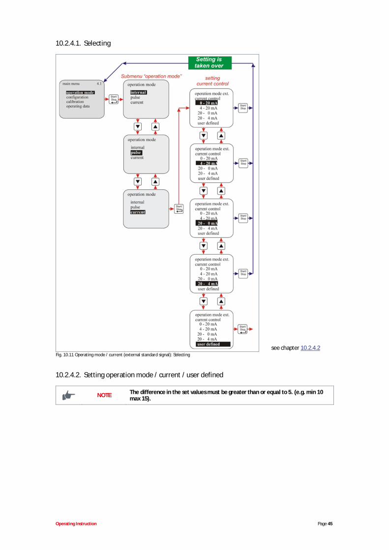
10.2.4.1. Selecting .............................................................................. 45
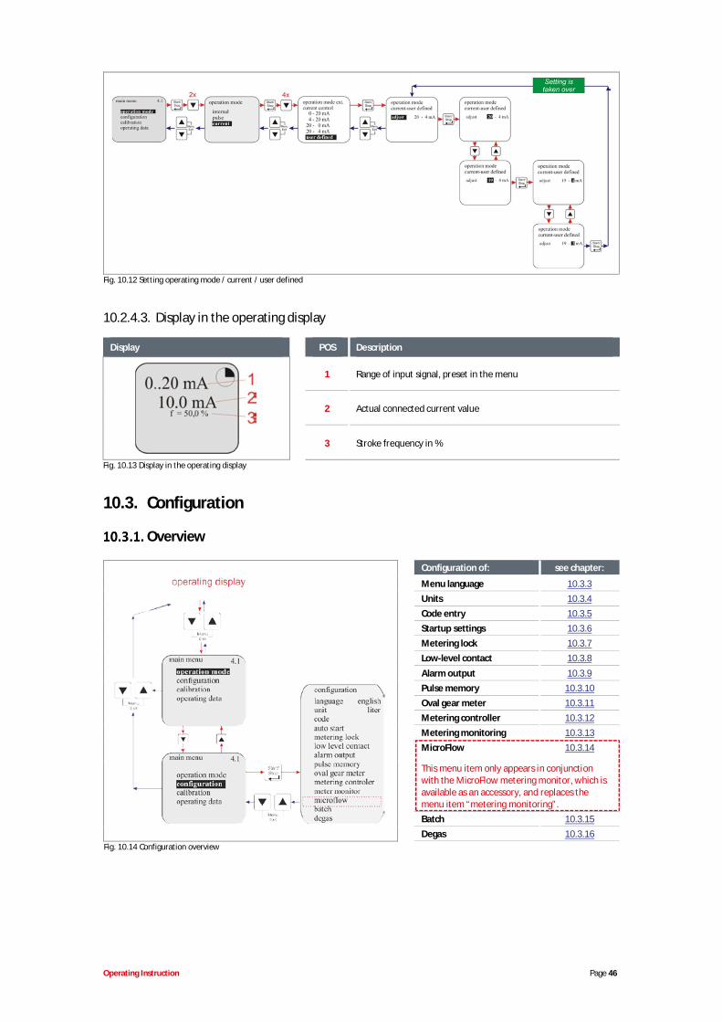
10.2.4.2. Setting operation mode / current / user defined .................. 45
10.2.4.3. Display in the operating display ........................................... 46
10.3. Configuration ........................................................................................................ 46
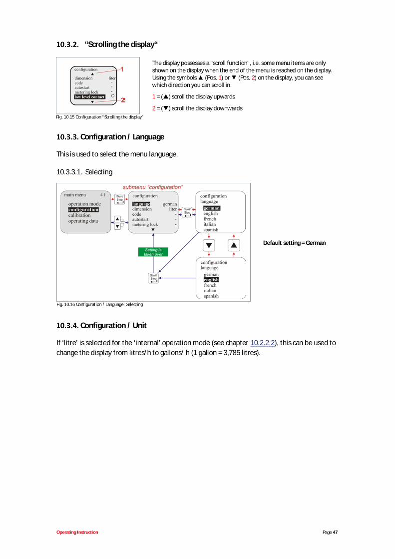
Overview .............................................................................................. 46
“Scrolling the display“ ........................................................................... 47
Configuration / Language ..................................................................... 47
10.3.3.1. Selecting .............................................................................. 47
Operating Instruction Page 5
Configuration / Unit .............................................................................. 47
10.3.4.1. Selecting .............................................................................. 48
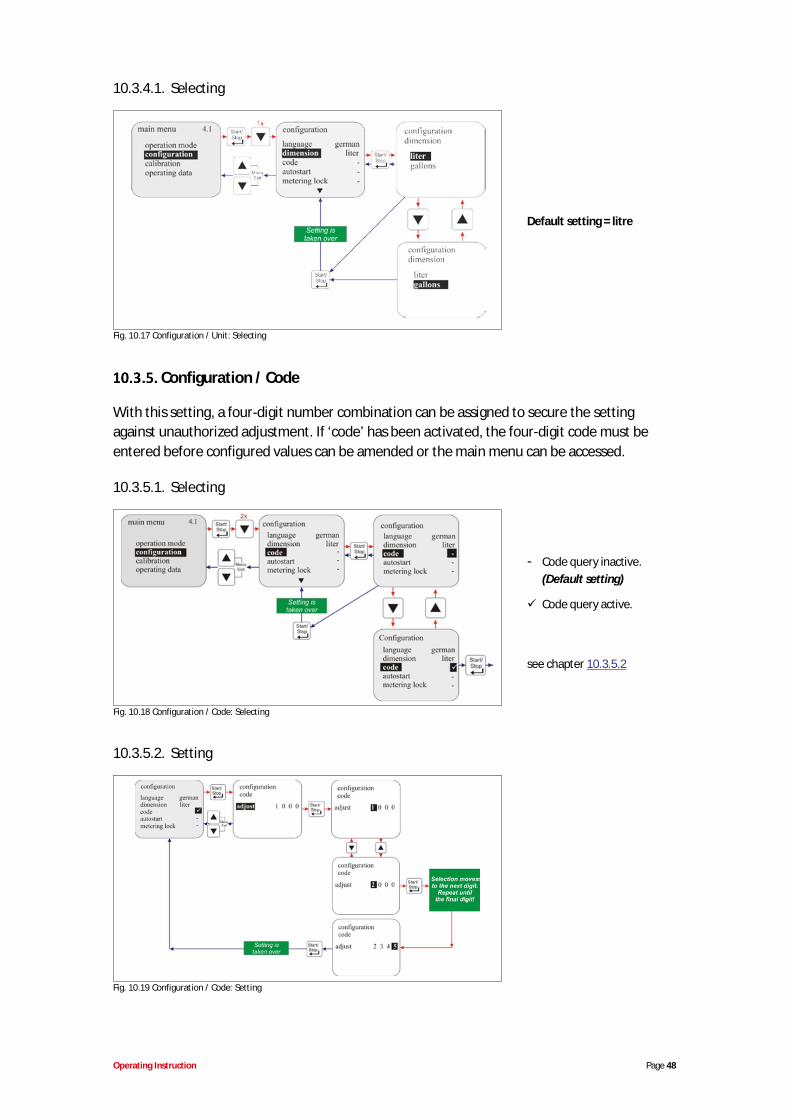
Configuration / Code ............................................................................ 48
10.3.5.1. Selecting .............................................................................. 48
10.3.5.2. Setting ................................................................................. 48
Configuration / Autostart...................................................................... 49
10.3.6.1. Selecting .............................................................................. 49
Configuration / Metering lock ............................................................... 49
10.3.7.1. Selecting .............................................................................. 49
Configuration / Low-level contact ......................................................... 49
10.3.8.1. Selecting .............................................................................. 50
Configuration / Alarm output................................................................ 50
10.3.9.1. Selecting .............................................................................. 50
10.3.9.2. Conversion from alarm relay mode to contact mode. .......... 50
Configuration / pulse memory .............................................................. 50
10.3.10.1. Selecting .............................................................................. 51
10.3.10.2. Display in the operating display with an active pulse memory ............................................................................................ 51
Configuration / Oval gear meter (only E60PLUS & OGMPLUS) .................... 51
10.3.11.1. Selecting .............................................................................. 52
Configuration / Metering controller (only E60PLUS & OGMPLUS) ............... 52
10.3.12.1. Selecting .............................................................................. 53
10.3.12.2. Display in the operating display with an active meteringcontroller............................................................................. 53
Configuration / Metering monitoring .................................................... 54
10.3.13.1. Selecting .............................................................................. 54
10.3.13.2. Metering monitoring / Stop pump ....................................... 54
10.3.13.3. Metering monitoring / Strokes ............................................. 55
10.3.13.4. Metering monitoring / Deviation (only at E60PLUS & OGM orOGMPLUS) ............................................................................. 55
10.3.13.5. Metering monitoring / Input (only at E60 WITHOUT Donglebox) ..................................................................................... 55
10.3.13.6. Oval gear meter pulse display (only E60PLUS) ......................... 56
Configuration / MicroFlowPLUS ............................................................... 56
10.3.14.1. Selecting .............................................................................. 57
10.3.14.2. MicroFlowPLUS / Stop pump .................................................. 57
10.3.14.3. MicroFlowPLUS / Strokes ........................................................ 57
Operating Instruction Page 6
10.3.14.4. MicroFlowPLUS / Deviation .................................................... 58
10.3.14.5. MicroFlowPLUS / Metering break ........................................... 58
10.3.14.6. MicroFlowPLUS / Metering delay ............................................ 58
10.3.14.7. MicroFlowPLUS / Calibration .................................................. 59
Configuration / Batch ........................................................................... 59
10.3.15.1. Selecting .............................................................................. 60
10.3.15.2. Batch / Quantity .................................................................. 60
10.3.15.3. Batch / Input (only at E60 WITHOUT Dongle-box) ................ 61
10.3.15.4. Display in the operating display ........................................... 61
Configuration DegasPLUS ........................................................................ 61
10.3.16.1. Selecting .............................................................................. 62
10.3.16.2. DegasPLUS / Degas strokes ..................................................... 62
10.3.16.3. DegasPLUS / Degas break ....................................................... 62
10.4. Calibration ............................................................................................................ 63
Overview .............................................................................................. 63
Calibration / pump ............................................................................... 63
10.4.2.1. Preparation ......................................................................... 63
10.4.2.2. Calibration / Start ................................................................ 64
Calibration / pump with oval gear meter (OGMPLUS) .............................. 64
10.4.3.1. Preparation ......................................................................... 64
10.4.3.2. Calibration / Start ................................................................ 65
Calibration / Manual ............................................................................. 65
10.4.4.1. Calibration data table .......................................................... 66
10.5. Operating data ...................................................................................................... 66
Overview .............................................................................................. 66
Operating data / Operating hours ......................................................... 66
10.5.2.1. Selecting / Displaying / Deleting........................................... 66
Operating data / Litre ........................................................................... 67
10.5.3.1. Selecting / Displaying / Deleting........................................... 67
Operating data / Amount of pulses ....................................................... 67
10.5.4.1. Selecting / Displaying / Deleting........................................... 67
11. Maintenance ....................................................................................................... 68
11.1. Replacing the suction / pressure valve and metering cartridges............................. 68
3 Ball-Valve (V3), 1,4 – 2,5 l/h for type: V3014 - V3025 ......................... 69
2 Ball-Valves ......................................................................................... 69

Operating Instruction Page 7
Inserting the metering valves in the correct positions ........................... 70
Changing the valve cartridges, type V3 ................................................. 70
11.2. Replacing the diaphragm and pump head ............................................................. 71
11.3. Aligning the mechanical stroke adjustment ........................................................... 71
12. Operating faults ................................................................................................... 73
12.1. Metering warning messages (display) .................................................................... 73
12.2. Alarm messages (display) ...................................................................................... 74
Deactivating of Dongle Box, OGM PLUS, MicroFlow PLUS in the pumpsoftware ............................................................................................... 75
12.3. Trouble shooting ................................................................................................... 75
13. Wearing parts and spare parts (standard version) ............................................... 77
13.1. Exploded drawing / list of parts type V3014, V3025, 00043, 00048, 00072 and type00112 .................................................................................................................... 77
13.2. Wearing part set types V3014, V3025, 00043, 00048, 00072 and type 00112 ........ 78
13.3. Pump head – Service set “Higher pressure” (1.6 MPa / 16 bar) .............................. 79
13.4. Exploded drawing / list of parts, type 00240 .......................................................... 79
13.5. Wearing part set – type 00240 .............................................................................. 80
14. Technical Specifications ....................................................................................... 81
14.1. Pump keys............................................................................................................. 81
Pump key 1 ........................................................................................... 81
Pump key 2 ........................................................................................... 82
Pump key definition.............................................................................. 82
14.2. Dimensions ........................................................................................................... 83
Type V3014, V3025, 00043, 00048, 00072 and type 00112 ................... 83
Type 00240 ........................................................................................... 84
14.3. Technical specifications "Overview tables" ............................................................ 84
General data - Standard pumps ............................................................ 85
Deviant general data - Pumps in the “Higher Pressures (HP)” version ... 85
Materials .............................................................................................. 85
In-/ and output circuit .......................................................................... 86
14.3.4.1. Connector I .......................................................................... 86
14.3.4.2. Connector II ......................................................................... 86
14.3.4.3. Connector III ........................................................................ 86
Operating Instruction Page 8
Connector assignments ........................................................................ 87
14.3.5.1. Pin assignment / conductor coloring Connector I (3-terminal) ............................................................................................ 87
14.3.5.2. Pin assignment / conductor coloring Connector II (5-terminal) ............................................................................................ 87
14.3.5.3. Pin assignment / conductor coloring Connector III (4-terminal) ............................................................................................ 87
14.4. Metering rates ...................................................................................................... 88
14.5. Delivery capacity depending on the backpressure and stroke setting .................... 88
Delivery capacity type V3014 / 1 MPa (10 bar) ...................................... 88
Delivery capacity type V3014 / 1,6 MPa (16 bar) (special version: higherpressures) ............................................................................................. 89
Delivery capacity type V3025 / 1 MPa (10 bar) ...................................... 89
Delivery capacity type 00043 / 1,6 MPa (16 bar) / (special version: higherpressures) ............................................................................................. 90
Delivery capacity type 00043 / 1 MPa (10 bar) ...................................... 90
Delivery capacity type 00043 / 1,6 MPa (16 bar) / (special version: higherpressures) ............................................................................................. 91
Delivery capacity type 00048 / 0,4 MPa (4 bar) ..................................... 91
Delivery capacity type 00072 / 0,6 MPa (6 bar) ..................................... 92
Delivery capacity type 00072 / 1 MPa (10 bar) ...................................... 92
Delivery capacity type 00112 / 0,5 MPa (5 bar) ..................................... 93
Delivery capacity type 00240 / 0,2 MPa (2 bar) ..................................... 93
15. Declaration of Conformity ................................................................................... 94
Operating Instruction Page 9
1. GENERALThis operating instruction contains all of the instructions for installing, starting up, maintainingand repairing diaphragm metering pumps of the ELADOS® EMP II E60 and EMP II E60PLUS
IMPORTANT Please note your pump’s software version when using these operating instruction(see chapter 9.6).
NOTEThe German sections of this manual constitute the ORIGINAL OPERATINGMANUAL and take legal precedence.All other languages are translations of the ORIGINAL OPERATING MANUAL.
If you have any questions, please contact us under the contact details given in chapter 1.4“Contact address / manufacturer”
1.1. EBS numbers
Within this operating instructions article numbers and EBS numbers are represented. EBSnumbers are Ecolab internal article numbers and used only “concern internal”.
1.2. Transport damage
CAUTIONIf there is discovered a transport damage while unpacking the pump, it must notbe installed.
WARNING
1.3. Warranty coverage
Operational safety, reliability and performance of this model are only guaranteed by themanufacturer if the following conditions are met:
Mounting, connections, adjustment, service and repair are performed by authorizedand trained personnel.
The diaphragm metering pump must be used according to the specifications in theoperating instructions contained in the delivery scope.
Only original spare parts must be used for repairs.
The warranty claim is invalidated if the pump housing is opened.
1.4. Contact address / Manufacturer
Operating Instruction Page 10
2. SAFETY
CAUTIONSafety notes and emphasized texts have to be observed in either case!
WARNING
2.1. Safety notes
Connection and repair work on the diaphragm metering pump must only beperformed by authorized technical personnel.
The power supply plug must always be disconnected before starting any work onelectrical components.
Appropriate protective clothing must be worn for any maintenance and repair work.
The safety regulations for handling chemicals must always be observed.
2.2. Emphases
The emphases indicated in this maintenance guide have the following meanings:
CAUTION
Used when improper compliance or non-compliance with the operatinginstructions, work instructions, prescribed working routines, et cetera, may resultin injury or accidents.
WARNINGUsed when improper compliance or non-compliance with the operatinginstructions, work instructions, prescribed working routines, et cetera, may resultin damage to the equipment.
IMPORTANT Used when particular attention is required in operating the equipment.
NOTE Used to draw attention to a noteworthy detail.
2.3. Enumerations
Enumerations marked with this sign ( ) describe an activity which must only beperformed by the installer / user.
2.4. Special safety notes for maintenance and repair work
CAUTION
Prior to repair and maintenance work and metering of dangerous media, alwaysrinse the metering head, relieve the pressure pipe and wear protective clothing(protective goggles, gloves and apron).Electronics repairs must only be performed by trained electricians, following thesafety regulations of the professional association VB G 4 & ZH 1/11)!When opening covers or removing parts, components carrying live voltages maybe exposed. Connection points may also be under live voltages.
IMPORTANT Only original spare parts must be used for repairs.
Operating Instruction Page 11
3. DELIVERY SCOPEThe delivery scope consists of:
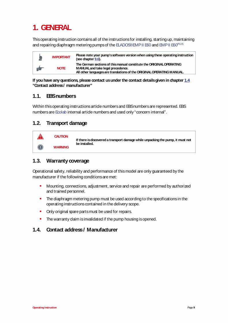
metering pump, version EMP II E 60 including mainpower supply cable (2 m) with shock-proof plug anddummy plug for inputs and outputs
Fig. 3.1 Delivery scope: metering pump
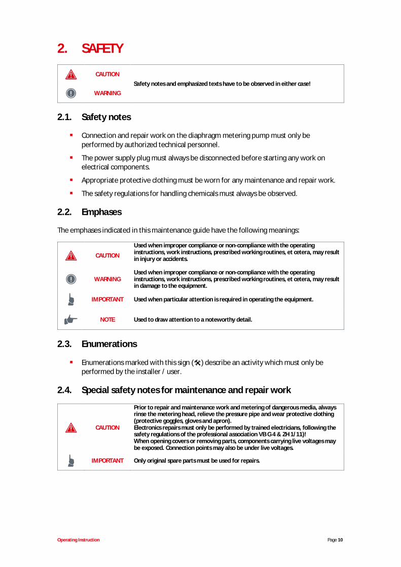
5-terminal connector plug for pulsed or standardsignal input
Fig. 3.2 Delivery scope: 5-terminal connector
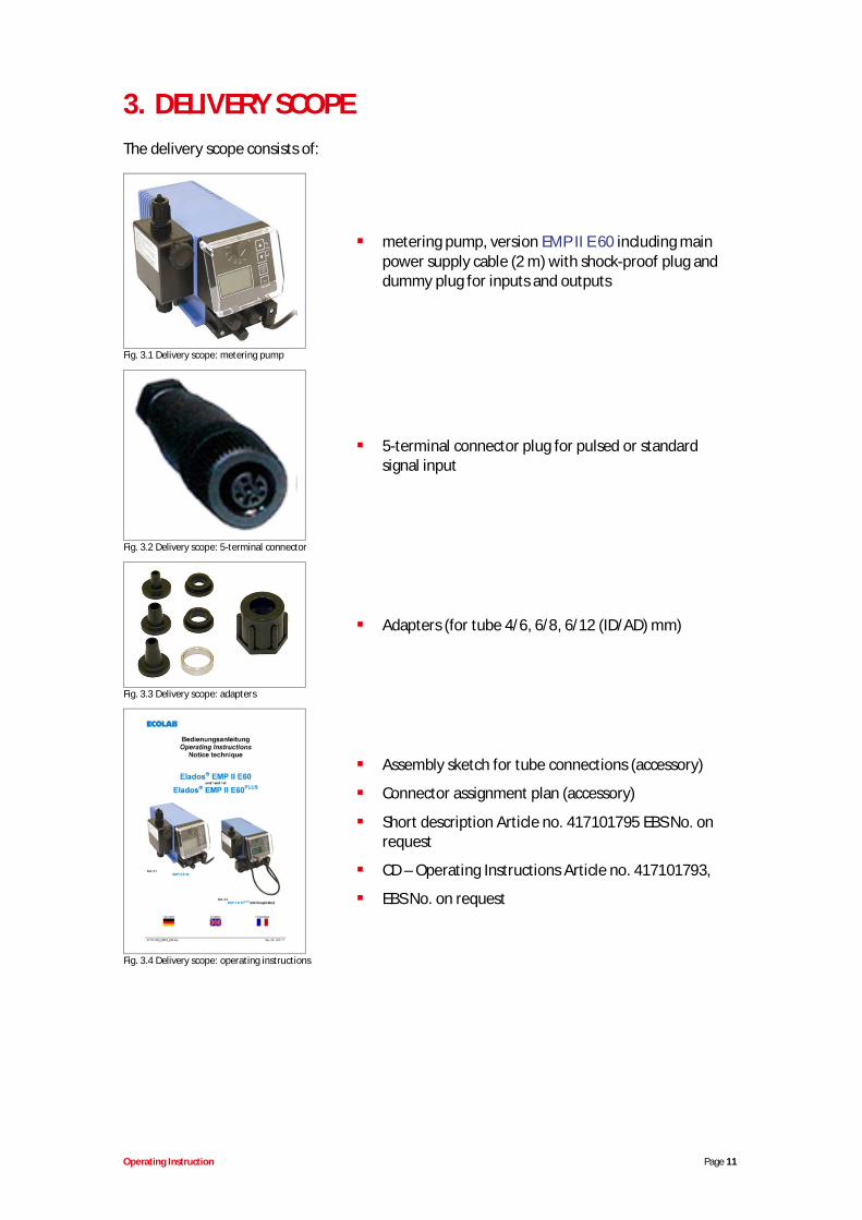
Adapters (for tube 4/6, 6/8, 6/12 (ID/AD) mm)
Fig. 3.3 Delivery scope: adapters
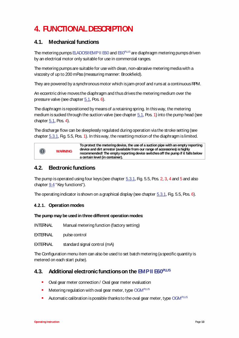
Assembly sketch for tube connections (accessory)
Connector assignment plan (accessory)
Short description Article no. 417101795 EBS No. onrequest
CD – Operating Instructions Article no. 417101793,
EBS No. on request
Fig. 3.4 Delivery scope: operating instructions

Operating Instruction Page 12
3.1. Upgrade accessories for the EMP II E60PLUS
Dongle box Article no. 248606 EBS No. 10016094
Fig. 3.5 Upgrade accessories: Dongle box
Operating Instruction Page 13
4. FUNCTIONAL DESCRIPTION4.1. Mechanical functions
The metering pumps ELADOS® EMP II E60 and E60PLUS are diaphragm metering pumps drivenby an electrical motor only suitable for use in commercial ranges.
The metering pumps are suitable for use with clean, non-abrasive metering media with aviscosity of up to 200 mPas (measuring manner: Brookfield).
They are powered by a synchronous motor which is jam-proof and runs at a continuous RPM.
An eccentric drive moves the diaphragm and thus drives the metering medium over thepressure valve (see chapter 5.1, Pos. 6).
The diaphragm is repositioned by means of a retaining spring. In this way, the meteringmedium is sucked through the suction valve (see chapter 5.1, Pos. 1) into the pump head (seechapter 5.1, Pos. 4).
The discharge flow can be sleeplessly regulated during operation via the stroke setting (seechapter 5.3.1, Fig. 5.5, Pos. 1). In this way, the resetting motion of the diaphragm is limited.
WARNING
To protect the metering device, the use of a suction pipe with an empty reportingdevice and dirt arrestor (available from our range of accessories) is highlyrecommended! The empty reporting device switches off the pump if it falls belowa certain level (in container).
4.2. Electronic functions
The pump is operated using four keys (see chapter 5.3.1, Fig. 5.5, Pos. 2, 3, 4 and 5 and alsochapter 9.4 “Key functions").
The operating indicator is shown on a graphical display (see chapter 5.3.1, Fig. 5.5, Pos. 6).
Operation modes
The pump may be used in three different operation modes:
INTERNAL Manual metering function (factory setting)
EXTERNAL pulse control
EXTERNAL standard signal control (mA)
The Configuration menu item can also be used to set batch metering (a specific quantity ismetered on each start pulse).
4.3. Additional electronic functions on the EMP II E60PLUS
Oval gear meter connection / Oval gear meter evaluation
Metering regulation with oval gear meter, type OGMPLUS
Automatic calibration is possible thanks to the oval gear meter, type OGMPLUS

Operating Instruction Page 14
Splitting of the metering lock/pulse/metering monitoring/oval gear meter inputs intomultiple connections to simplify the external connections.
Operating Instruction Page 15
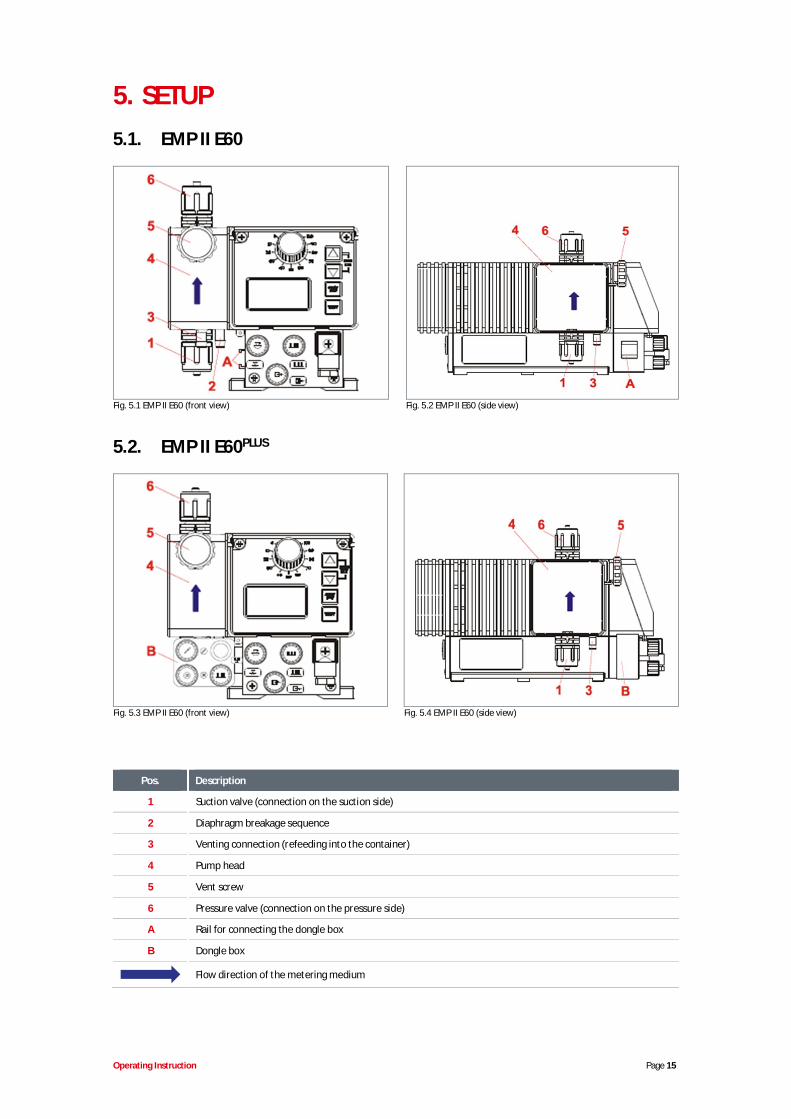
5. SETUP5.1. EMP II E60
Fig. 5.1 EMP II E60 (front view) Fig. 5.2 EMP II E60 (side view)
5.2. EMP II E60PLUS
Fig. 5.3 EMP II E60 (front view) Fig. 5.4 EMP II E60 (side view)
Pos. Description
1 Suction valve (connection on the suction side)
2 Diaphragm breakage sequence
3 Venting connection (refeeding into the container)
4 Pump head
5 Vent screw
6 Pressure valve (connection on the pressure side)
A Rail for connecting the dongle box
B Dongle box
Flow direction of the metering medium
Operating Instruction Page 16
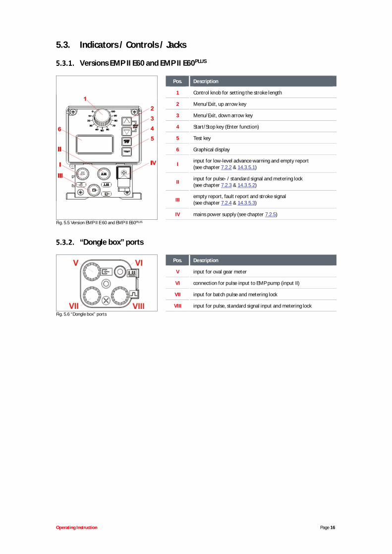
5.3. Indicators / Controls / Jacks
Versions EMP II E60 and EMP II E60PLUS
Pos. Description
1 Control knob for setting the stroke length
2 Menu/Exit, up arrow key
3 Menu/Exit, down arrow key
4 Start/Stop key (Enter function)
5 Test key
6 Graphical display
I input for low-level advance warning and empty report(see chapter 7.2.2 & 14.3.5.1)
II input for pulse- / standard signal and metering lock(see chapter 7.2.3 & 14.3.5.2)
IIIempty report, fault report and stroke signal(see chapter 7.2.4 & 14.3.5.3)
IV mains power supply (see chapter 7.2.5)Fig. 5.5 Version EMP II E 60 and EMP II E60PLUS
“Dongle box” ports
Pos. Description
V input for oval gear meter
VI connection for pulse input to EMP pump (input II)
VII input for batch pulse and metering lock
VIII input for pulse, standard signal input and metering lockFig. 5.6 “Dongle box” ports

Operating Instruction Page 17
6. MOUNTING
WARNING The installation must only be performed by authorized personnel and the generalguidelines and local installation regulations must be observed!
The metering pump should be fitted in an easy-to-access, frost-free location. Theambient temperature must not exceed +40° C.
The mounting position of the device must be horizontal.
The pump must be securely screwed to the bracket or the container using the drillholes provided (for information on the drill hole gap, see chapter 14.2 “Dimensions”).
6.1. Mounting diagram
Pos. Description
1 Overflow valve
2 Pressure control valve
3 Replacement method: Multifunction valve
4 Suction pipe / bottom admission valve
Fig. 6.1 Mounting diagram
NOTEThe metering valve, pressure control valve and pressure relief valve can bereplaced by a multifunction valve (MFV) from our product range, which combinesall of these functionalities.
Operating Instruction Page 18
7. DEVICE INSTALLATION7.1. Hydraulic installation
Installation examples
NOTE
The installation examples and applications provided here are of a functionalnature. They give an overview of installation types which are correct or to beavoided for the correct functioning of the pump.
WARNING
Specific measures and protection devices for the metering of dangerous oraggressive chemicals are not provided here.When using such chemicals, always observe the legal regulations and the relevantproduct datasheet.
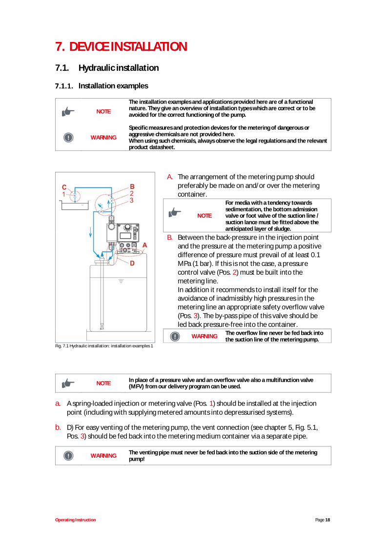
A. The arrangement of the metering pump shouldpreferably be made on and/or over the meteringcontainer.
NOTE
For media with a tendency towardssedimentation, the bottom admissionvalve or foot valve of the suction line /suction lance must be fitted above theanticipated layer of sludge.
B. Between the back-pressure in the injection pointand the pressure at the metering pump a positivedifference of pressure must prevail of at least 0.1MPa (1 bar). If this is not the case, a pressurecontrol valve (Pos. 2) must be built into themetering line.In addition it recommends to install itself for theavoidance of inadmissibly high pressures in themetering line an appropriate safety overflow valve(Pos. 3). The by-pass pipe of this valve should beled back pressure-free into the container.
WARNING The overflow line never be fed back intothe suction line of the metering pump.
Fig. 7.1 Hydraulic installation: installation examples 1
NOTE In place of a pressure valve and an overflow valve also a multifunction valve(MFV) from our delivery program can be used.
a. A spring-loaded injection or metering valve (Pos. 1) should be installed at the injectionpoint (including with supplying metered amounts into depressurised systems).
b. D) For easy venting of the metering pump, the vent connection (see chapter 5, Fig. 5.1,Pos. 3) should be fed back into the metering medium container via a separate pipe.
WARNING The venting pipe must never be fed back into the suction side of the meteringpump!
Operating Instruction Page 19
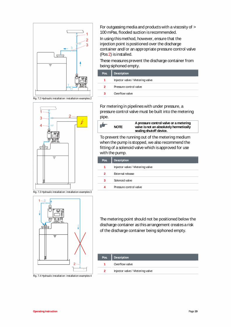
For outgassing media and products with a viscosity of >100 mPas, flooded suction is recommended.In using this method, however, ensure that theinjection point is positioned over the dischargecontainer and/or an appropriate pressure control valve(Pos 2) is installed.These measures prevent the discharge container frombeing siphoned empty.
Pos. Description
1 Injector valve / Metering valve
2 Pressure control valve
3 Overflow valveFig. 7.2 Hydraulic installation: installation examples 2
For metering in pipelines with under pressure, apressure control valve must be built into the meteringpipe.
NOTEA pressure control valve or a meteringvalve is not an absolutely hermeticallysealing shutoff device.
To prevent the running out of the metering mediumwhen the pump is stopped, we also recommend thefitting of a solenoid valve which is approved for usewith the pump.
Pos. Description
1 Injector valve / Metering valve
2 External release
3 Solenoid valve
4 Pressure control valveFig. 7.3 Hydraulic installation: installation examples 3
The metering point should not be positioned below thedischarge container as this arrangement creates a riskof the discharge container being siphoned empty.
Pos. Description
1 Overflow valve
2 Injector valve / Metering valveFig. 7.4 Hydraulic installation: installation examples 4
Operating Instruction Page 20
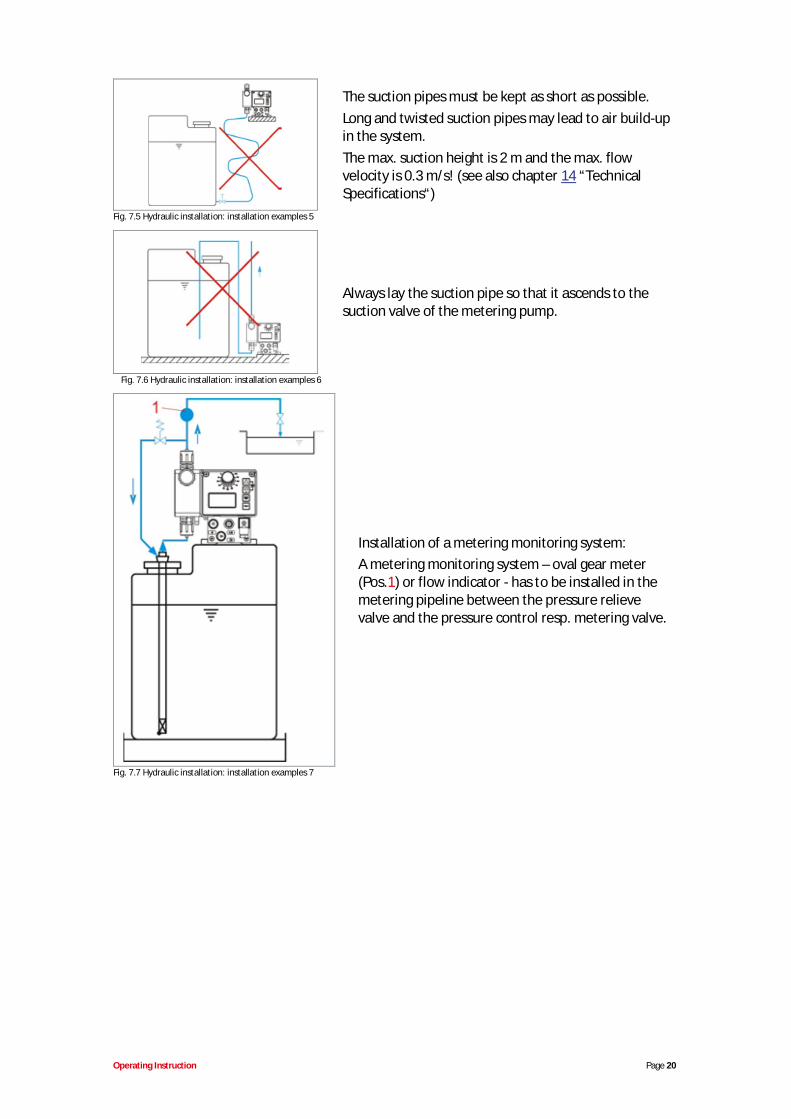
The suction pipes must be kept as short as possible.Long and twisted suction pipes may lead to air build-upin the system.The max. suction height is 2 m and the max. flowvelocity is 0.3 m/s! (see also chapter 14 “TechnicalSpecifications“)
Fig. 7.5 Hydraulic installation: installation examples 5
Always lay the suction pipe so that it ascends to thesuction valve of the metering pump.
Fig. 7.6 Hydraulic installation: installation examples 6
Installation of a metering monitoring system:A metering monitoring system – oval gear meter(Pos.1) or flow indicator - has to be installed in themetering pipeline between the pressure relievevalve and the pressure control resp. metering valve.
Fig. 7.7 Hydraulic installation: installation examples 7
Operating Instruction Page 21
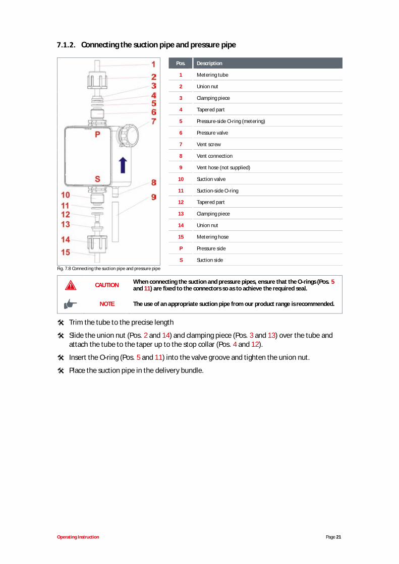
Connecting the suction pipe and pressure pipe
Pos. Description
1 Metering tube
2 Union nut
3 Clamping piece
4 Tapered part
5 Pressure-side O-ring (metering)
6 Pressure valve
7 Vent screw
8 Vent connection
9 Vent hose (not supplied)
10 Suction valve
11 Suction-side O-ring
12 Tapered part
13 Clamping piece
14 Union nut
15 Metering hose
P Pressure side
S Suction sideFig. 7.8 Connecting the suction pipe and pressure pipe
CAUTION When connecting the suction and pressure pipes, ensure that the O-rings (Pos. 5and 11) are fixed to the connectors so as to achieve the required seal.
NOTE The use of an appropriate suction pipe from our product range is recommended.
Trim the tube to the precise length
Slide the union nut (Pos. 2 and 14) and clamping piece (Pos. 3 and 13) over the tube andattach the tube to the taper up to the stop collar (Pos. 4 and 12).
Insert the O-ring (Pos. 5 and 11) into the valve groove and tighten the union nut.
Place the suction pipe in the delivery bundle.
Operating Instruction Page 22
7.2. Electrical installation
Inputs and outputs
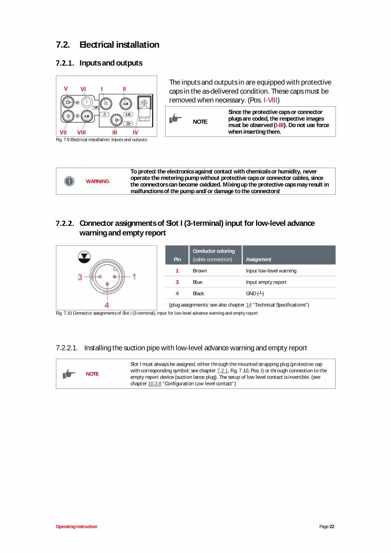
The inputs and outputs in are equipped with protectivecaps in the as-delivered condition. These caps must beremoved when necessary. (Pos. I-VIII)
NOTE
Since the protective caps or connectorplugs are coded, the respective imagesmust be observed (I-III). Do not use forcewhen inserting them.
Fig. 7.9 Electrical installation: Inputs and outputs
WARNING
To protect the electronics against contact with chemicals or humidity, neveroperate the metering pump without protective caps or connector cables, sincethe connectors can become oxidized. Mixing up the protective caps may result inmalfunctions of the pump and/or damage to the connectors!
Connector assignments of Slot I (3-terminal) input for low-level advancewarning and empty report
Pin
Conductor coloring
(cable connection) Assignment
1 Brown Input low-level warning
3 Blue Input empty report
4 Black GND ( )
(plug assignments: see also chapter 14 “Technical Specifications“)Fig. 7.10 Connector assignments of Slot I (3-terminal), input for low-level advance warning and empty report
7.2.2.1. Installing the suction pipe with low-level advance warning and empty report
NOTE
Slot I must always be assigned, either through the mounted strapping plug (protective capwith corresponding symbol; see chapter 7.2.1, Fig. 7.10, Pos. I) or through connection to theempty report device (suction lance plug). The setup of low level contact is invertible. (seechapter 10.3.8 “Configuration Low level contact“)
Operating Instruction Page 23
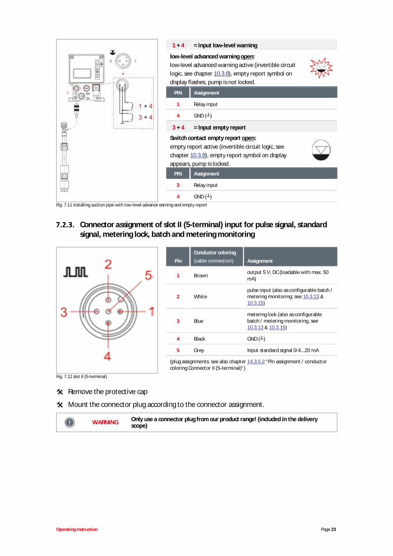
1 + 4 = Input low-level warning
low-level advanced warning open:low-level advanced warning active (invertible circuitlogic, see chapter 10.3.8), empty report symbol ondisplay flashes, pump is not locked.
PIN Assignment
1 Relay input
4 GND ( )
3 + 4 = Input empty report
Switch contact empty report open:empty report active (invertible circuit logic, seechapter 10.3.8), empty report symbol on displayappears, pump is locked.
PIN Assignment
3 Relay input
4 GND ( )Fig. 7.11 Installing suction pipe with low-level advance earning and empty report
Connector assignment of slot II (5-terminal) input for pulse signal, standardsignal, metering lock, batch and metering monitoring
Pin
Conductor coloring(cable connection) Assignment
1 Brown output 5 V, DC (loadable with max. 50mA)
2 Whitepulse input (also as configurable batch /metering monitoring; see 10.3.13 &10.3.15)
3 Bluemetering lock (also as configurablebatch / metering monitoring, see10.3.13 & 10.3.15)
4 Black GND ( )
5 Grey Input standard signal 0/4...20 mA
(plug assignments: see also chapter 14.3.5.2 “Pin assignment / conductorcoloring Connector II (5-terminal)“)
Fig. 7.12 slot II (5-terminal)
Remove the protective cap
Mount the connector plug according to the connector assignment.
WARNING Only use a connector plug from our product range! (included in the deliveryscope)
Operating Instruction Page 24
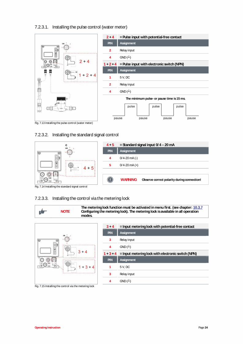
7.2.3.1. Installing the pulse control (water meter)
2 + 4 = Pulse input with potential-free contact
PIN Assignment
2 Relay input
4 GND ( )
1 + 2 + 4 = Pulse input with electronic switch (NPN)
PIN Assignment
1 5 V, DC
2 Relay input
4 GND ( )
The minimum pulse- or pause time is 15 ms.
Fig. 7.13 Installing the pulse control (water meter)
7.2.3.2. Installing the standard signal control
c 4 + 5 = Standard signal input 0/4 – 20 mA
PIN Assignment
4 0/4-20 mA (-)
5 0/4-20 mA (+)
WARNING Observe correct polarity during connection!
Fig. 7.14 Installing the standard signal control
7.2.3.3. Installing the control via the metering lock
NOTEThe metering lock function must be activated in menu first. (see chapter: 10.3.7Configuring the metering lock). The metering lock is available in all operationmodes.
3 + 4 = Input metering lock with potential-free contact
PIN Assignment
3 Relay input
4 GND ( )
1 + 3 + 4 = Input metering lock with electronic switch (NPN)
PIN Assignment
1 5 V, DC
3 Relay input
4 GND ( )Fig. 7.15 Installing the control via the metering lock

Operating Instruction Page 25
7.2.3.4. Installing the batch function
NOTEThe batch function must be activated in menu first. The selection must also bemade of whether the pins 2+4 (input “pulse”) or 3+4 (input “metering lock”)should be used for the batch metering start pulse (see chapter 10.3.15.)
2 + 4 = Input batch function with potential-free contact withselection input „pulse“ at configuration / batch (seechapter 10.3.15).
PIN Assignment
2 Relay input
4 GND ( )Fig. 7.16 Installing the batch function
1 + 2 + 4= Input batch function with electronic switch (NPN) with selection input „pulse“ atconfiguration / batch (see chapter 10.3.15).
PIN Assignment
1 5 V, DC
2 Relay input
4 GND ( )
or
3 + 4= Input batch function with potential-free contact with selection input „metering lock“ atconfiguration / batch (see chapter 10.3.15).
PIN Assignment
3 Relay input
4 GND ( )
1 + 3 + 4= Input batch function with electronic switch (NPN) with selection input „metering lock“ atconfiguration / batch (see chapter 10.3.15).
PIN Assignment
1 5 V, DC
3 Relay input
4 GND ( )
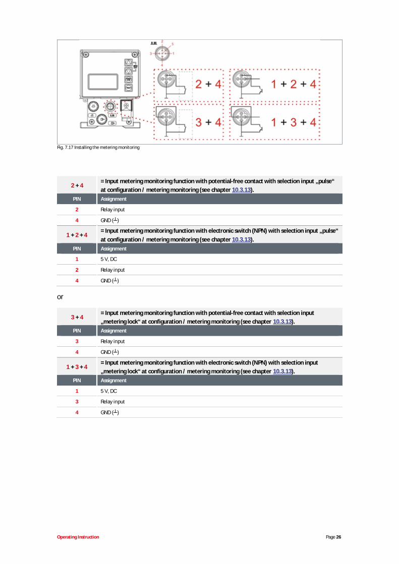
7.2.3.5. Installing the metering monitoring
NOTE
The metering monitoring function must be activated in menu first. The selectionmust also be made of whether the pins 2+4 (input “pulse”) or 3+4 (input“metering lock”) should be used for the metering monitoring input (see chapter10.3.13).
Operating Instruction Page 26
Fig. 7.17 Installing the metering monitoring
2 + 4= Input metering monitoring function with potential-free contact with selection input „pulse“at configuration / metering monitoring (see chapter 10.3.13).
PIN Assignment
2 Relay input
4 GND ( )
1 + 2 + 4= Input metering monitoring function with electronic switch (NPN) with selection input „pulse“at configuration / metering monitoring (see chapter 10.3.13).
PIN Assignment
1 5 V, DC
2 Relay input
4 GND ( )
or
3 + 4= Input metering monitoring function with potential-free contact with selection input„metering lock“ at configuration / metering monitoring (see chapter 10.3.13).
PIN Assignment
3 Relay input
4 GND ( )
1 + 3 + 4= Input metering monitoring function with electronic switch (NPN) with selection input„metering lock“ at configuration / metering monitoring (see chapter 10.3.13).
PIN Assignment
1 5 V, DC
3 Relay input
4 GND ( )
Operating Instruction Page 27
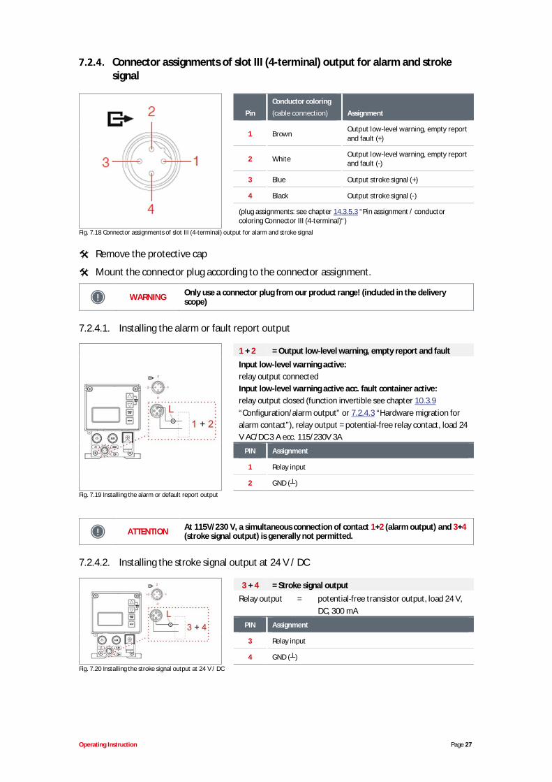
Connector assignments of slot III (4-terminal) output for alarm and strokesignal
Pin
Conductor coloring
(cable connection) Assignment
1 BrownOutput low-level warning, empty reportand fault (+)
2 White Output low-level warning, empty reportand fault (-)
3 Blue Output stroke signal (+)
4 Black Output stroke signal (-)
(plug assignments: see chapter 14.3.5.3 “Pin assignment / conductorcoloring Connector III (4-terminal)“)
Fig. 7.18 Connector assignments of slot III (4-terminal) output for alarm and stroke signal
Remove the protective cap
Mount the connector plug according to the connector assignment.
WARNING Only use a connector plug from our product range! (included in the deliveryscope)
7.2.4.1. Installing the alarm or fault report output
1 + 2 = Output low-level warning, empty report and fault
Input low-level warning active:relay output connectedInput low-level warning active acc. fault container active:relay output closed (function invertible see chapter 10.3.9“Configuration/alarm output” or 7.2.4.3 “Hardware migration foralarm contact”), relay output = potential-free relay contact, load 24V AC/DC 3 A ecc. 115/230V 3A
PIN Assignment
1 Relay input
2 GND ( )Fig. 7.19 Installing the alarm or default report output
ATTENTION At 115V/230 V, a simultaneous connection of contact 1+2 (alarm output) and 3+4(stroke signal output) is generally not permitted.
7.2.4.2. Installing the stroke signal output at 24 V / DC
3 + 4 = Stroke signal outputRelay output = potential-free transistor output, load 24 V,
DC, 300 mA
PIN Assignment
3 Relay input
4 GND ( )Fig. 7.20 Installing the stroke signal output at 24 V / DC
Operating Instruction Page 28
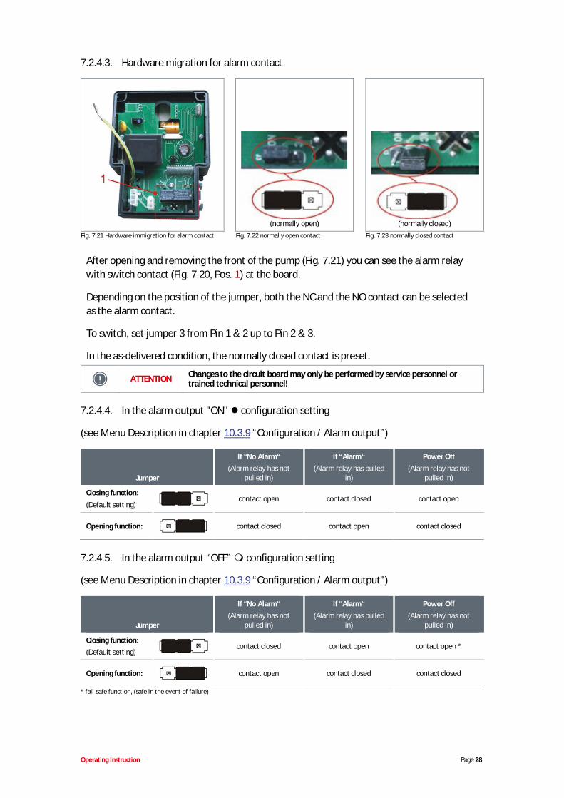
7.2.4.3. Hardware migration for alarm contact
(normally open) (normally closed)Fig. 7.21 Hardware immigration for alarm contact Fig. 7.22 normally open contact Fig. 7.23 normally closed contact
After opening and removing the front of the pump (Fig. 7.21) you can see the alarm relaywith switch contact (Fig. 7.20, Pos. 1) at the board.
Depending on the position of the jumper, both the NC and the NO contact can be selectedas the alarm contact.
To switch, set jumper 3 from Pin 1 & 2 up to Pin 2 & 3.
In the as-delivered condition, the normally closed contact is preset.
ATTENTION Changes to the circuit board may only be performed by service personnel ortrained technical personnel!
7.2.4.4. In the alarm output "ON" configuration setting
(see Menu Description in chapter 10.3.9 “Configuration / Alarm output”)
Jumper
If “No Alarm“(Alarm relay has not
pulled in)
If “Alarm“(Alarm relay has pulled
in)
Power Off(Alarm relay has not
pulled in)
Closing function:
(Default setting)contact open contact closed contact open
Opening function: contact closed contact open contact closed
7.2.4.5. In the alarm output “OFF” configuration setting
(see Menu Description in chapter 10.3.9 “Configuration / Alarm output”)
Jumper
If “No Alarm“(Alarm relay has not
pulled in)
If “Alarm“(Alarm relay has pulled
in)
Power Off(Alarm relay has not
pulled in)
Closing function:(Default setting)
contact closed contact open contact open *
Opening function: contact open contact closed contact closed
* fail-safe function, (safe in the event of failure)
Operating Instruction Page 29
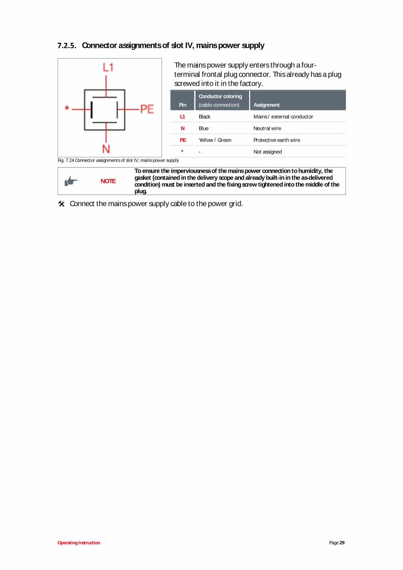
Connector assignments of slot IV, mains power supply
The mains power supply enters through a four-terminal frontal plug connector. This already has a plugscrewed into it in the factory.
Pin
Conductor coloring
(cable connection) Assignment
L1 Black Mains / external conductor
N Blue Neutral wire
PE Yellow / Green Protective earth wire
* - Not assignedFig. 7.24 Connector assignments of slot IV, mains power supply
NOTE
To ensure the imperviousness of the mains power connection to humidity, thegasket (contained in the delivery scope and already built-in in the as-deliveredcondition) must be inserted and the fixing screw tightened into the middle of theplug.
Connect the mains power supply cable to the power grid.
Operating Instruction Page 30
8. UPGRADING THE EMPII E60 TO THE EMPIIE60PLUS
To upgrade the EMP II E60 to the EMP II E60PLUS and thus access the additional functions,obtain the dongle box or the MicroFlow PLUS from our range of accessories.
The dongle box is a slot extension, as well as a means of connecting an oval gear meter formeasuring the metering rate. If the dongle box is fitted and is activated by switching the pumpoff and then on again, "E60+" appears on the bottom left of the pump's display unit. If anOGM PLUS (oval gear meter) is connected to slot V on the dongle box and is activated byswitching the pump off and then on again, "E60++" appears on the pump's display unit, andthe oval gear meter function is automatically enabled under Configuration in the Pump menu.
In addition to the slot expansion, the MicroFlow PLUS enables a special flow rate monitoringsensor to be analysed via conductivity measurements. When the MicroFlow box is connectedand is activated by switching the pump off and then on again, "E60+microflow" appears on thebottom left of the pump's display unit, and the MicroFlow function is automatically enabled inthe appropriate sub-menu under Configuration in the Pump menu.
If the pump software recognises that there is a dongle box, OGM PLUS or MicroFlow boxconnected, and the communication is then interrupted between the pump and the peripheralunit (through the removal of the unit, for example), an error message is displayed (see chapter12.2 "Alarm signals (Display)"). To prevent this error message appearing repeatedly, thecommunication (connection) must be restored, or the analysis must be disabled in the pumpsoftware (see chapter 12.2.1 "Disabling a dongle box, OGMPLUS, MicroFlowPLUS in the pumpsoftware").
The only outward difference between a dongle box and a MicroFlow box is a sticker with theappropriate item number (dongle box Art. No. 248606, EBS No. 10016094, MicroFlow box Art.No. 248611, EBS No. on request)
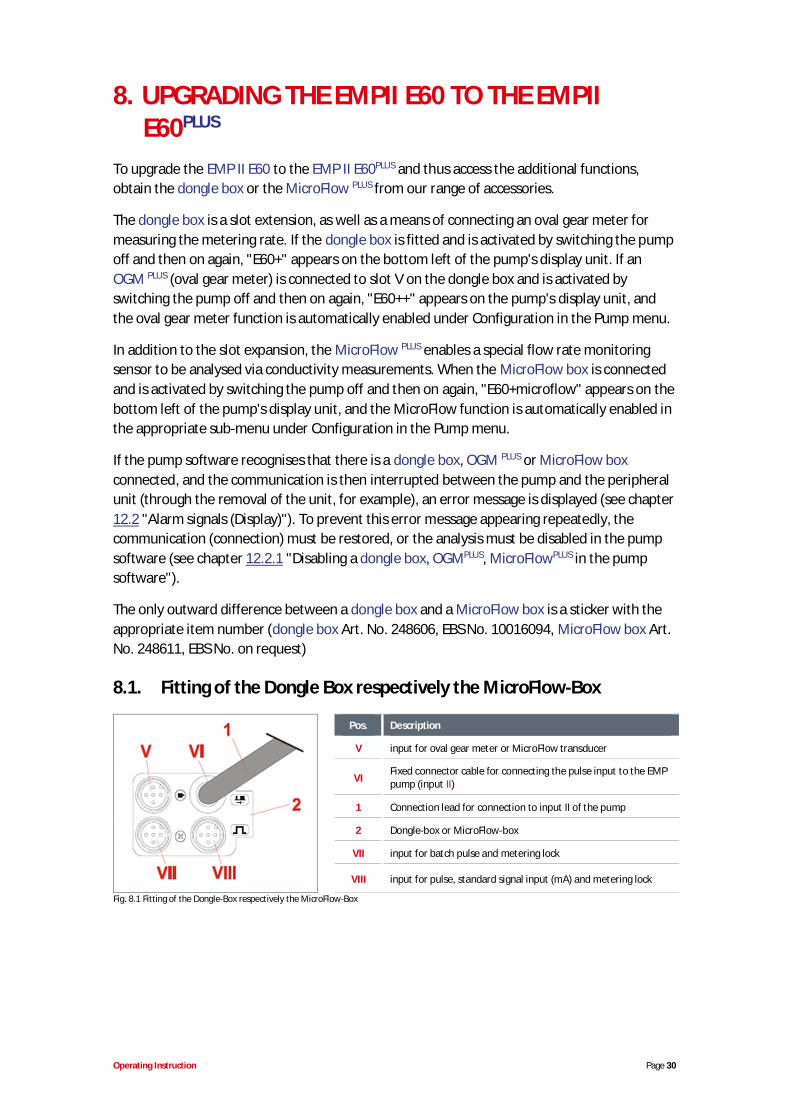
8.1. Fitting of the Dongle Box respectively the MicroFlow-Box
Pos. Description
V input for oval gear meter or MicroFlow transducer
VIFixed connector cable for connecting the pulse input to the EMPpump (input II)
1 Connection lead for connection to input II of the pump
2 Dongle-box or MicroFlow-box
VII input for batch pulse and metering lock
VIII input for pulse, standard signal input (mA) and metering lock
Fig. 8.1 Fitting of the Dongle-Box respectively the MicroFlow-Box
Operating Instruction Page 31
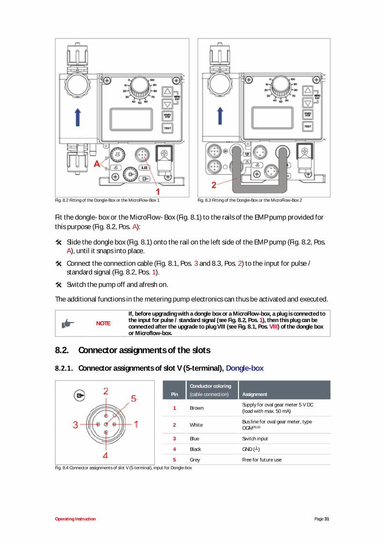
Fig. 8.2 Fitting of the Dongle-Box or the MicroFlow-Box 1 Fig. 8.3 Fitting of the Dongle-Box or the MicroFlow-Box 2
Fit the dongle- box or the MicroFlow- Box (Fig. 8.1) to the rails of the EMP pump provided forthis purpose (Fig. 8.2, Pos. A):
Slide the dongle box (Fig. 8.1) onto the rail on the left side of the EMP pump (Fig. 8.2, Pos.A), until it snaps into place.
Connect the connection cable (Fig. 8.1, Pos. 3 and 8.3, Pos. 2) to the input for pulse /standard signal (Fig. 8.2, Pos. 1).
Switch the pump off and afresh on.
The additional functions in the metering pump electronics can thus be activated and executed.
NOTE
If, before upgrading with a dongle box or a MicroFlow-box, a plug is connected tothe input for pulse / standard signal (see Fig. 8.2, Pos. 1), then this plug can beconnected after the upgrade to plug VIII (see Fig. 8.1, Pos. VIII) of the dongle boxor Microflow-box.
8.2. Connector assignments of the slots
Connector assignments of slot V (5-terminal), Dongle-box
Pin
Conductor coloring
(cable connection) Assignment
1 Brown Supply for oval gear meter 5 V DC(load with max. 50 mA)
2 White Bus line for oval gear meter, typeOGMPLUS
3 Blue Switch input
4 Black GND ( )
5 Grey Free for future useFig. 8.4 Connector assignments of slot V (5-terminal), input for Dongle-box
Operating Instruction Page 32
Remove the protective cap
Mount the connector plug according to the connector assignment.
WARNING Only use a connector plug from our product range!
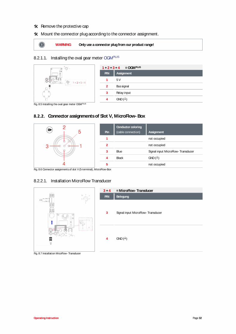
8.2.1.1. Installing the oval gear meter OGMPLUS
1 + 2 + 3 + 4 = OGMPLUS
PIN Assignment
1 5 V
2 Bus signal
3 Relay input
4 GND ( )Fig. 8.5 Installing the oval gear meter OGMPLUS
Connector assignments of Slot V, MicroFlow- Box
Pin
Conductor coloring
(cable connection) Assignment
1 not occupied
2 not occupied
3 Blue Signal input MicroFlow- Transducer
4 Black GND ( )
5 not occupiedFig. 8.6 Connector assignments of slot V (5-terminal), MicroFlow-Box
8.2.2.1. Installation MicroFlow Transducer
3 + 4 = MicroFlow- Transducer
PIN Belegung
3 Signal input MicroFlow- Transducer
4 GND ( )
Fig. 8.7 Installation MicoFlow- Transducer
Operating Instruction Page 33
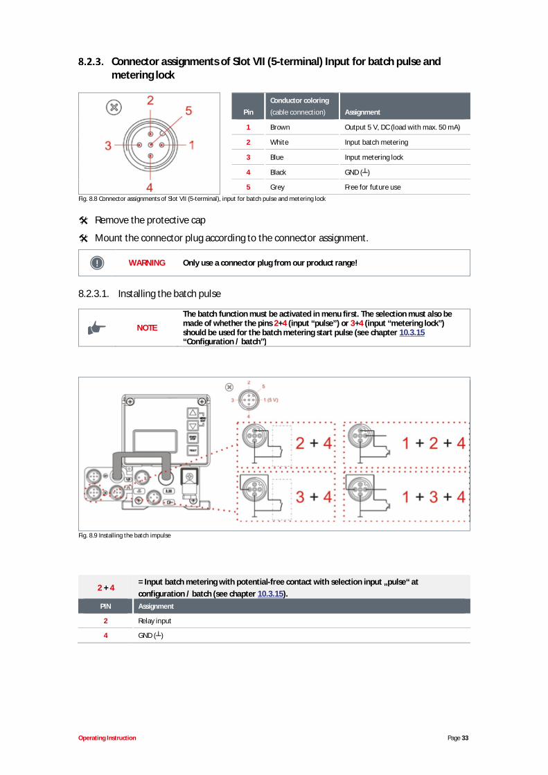
Connector assignments of Slot VII (5-terminal) Input for batch pulse andmetering lock
Pin
Conductor coloring
(cable connection) Assignment
1 Brown Output 5 V, DC (load with max. 50 mA)
2 White Input batch metering
3 Blue Input metering lock
4 Black GND ( )
5 Grey Free for future useFig. 8.8 Connector assignments of Slot VII (5-terminal), input for batch pulse and metering lock
Remove the protective cap
Mount the connector plug according to the connector assignment.
WARNING Only use a connector plug from our product range!
8.2.3.1. Installing the batch pulse
NOTE
The batch function must be activated in menu first. The selection must also bemade of whether the pins 2+4 (input “pulse”) or 3+4 (input “metering lock”)should be used for the batch metering start pulse (see chapter 10.3.15“Configuration / batch”)
Fig. 8.9 Installing the batch impulse
2 + 4= Input batch metering with potential-free contact with selection input „pulse“ atconfiguration / batch (see chapter 10.3.15).
PIN Assignment
2 Relay input
4 GND ( )
Operating Instruction Page 34
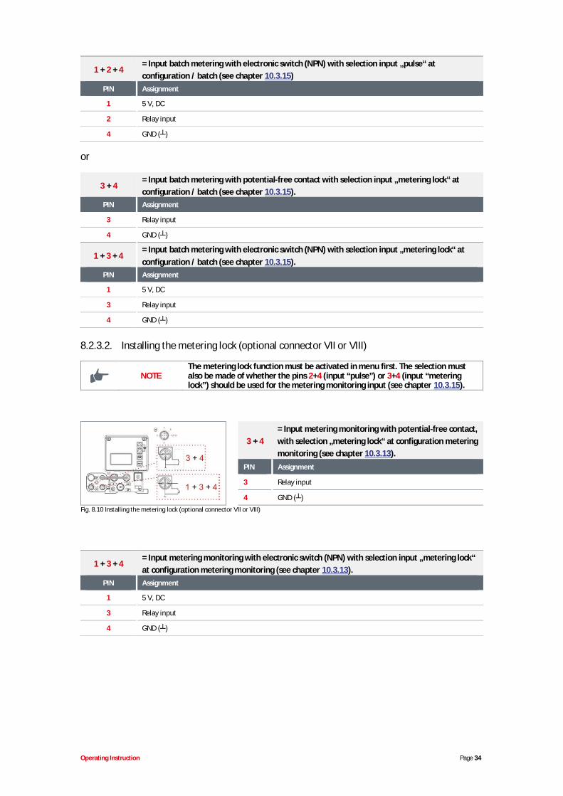
1 + 2 + 4= Input batch metering with electronic switch (NPN) with selection input „pulse“ atconfiguration / batch (see chapter 10.3.15)
PIN Assignment
1 5 V, DC
2 Relay input
4 GND ( )
or
3 + 4= Input batch metering with potential-free contact with selection input „metering lock“ atconfiguration / batch (see chapter 10.3.15).
PIN Assignment
3 Relay input
4 GND ( )
1 + 3 + 4= Input batch metering with electronic switch (NPN) with selection input „metering lock“ atconfiguration / batch (see chapter 10.3.15).
PIN Assignment
1 5 V, DC
3 Relay input
4 GND ( )
8.2.3.2. Installing the metering lock (optional connector VII or VIII)
NOTEThe metering lock function must be activated in menu first. The selection mustalso be made of whether the pins 2+4 (input “pulse”) or 3+4 (input “meteringlock”) should be used for the metering monitoring input (see chapter 10.3.15).
3 + 4= Input metering monitoring with potential-free contact,with selection „metering lock“ at configuration meteringmonitoring (see chapter 10.3.13).
PIN Assignment
3 Relay input
4 GND ( )Fig. 8.10 Installing the metering lock (optional connector VII or VIII)
1 + 3 + 4= Input metering monitoring with electronic switch (NPN) with selection input „metering lock“at configuration metering monitoring (see chapter 10.3.13).
PIN Assignment
1 5 V, DC
3 Relay input
4 GND ( )
Operating Instruction Page 35
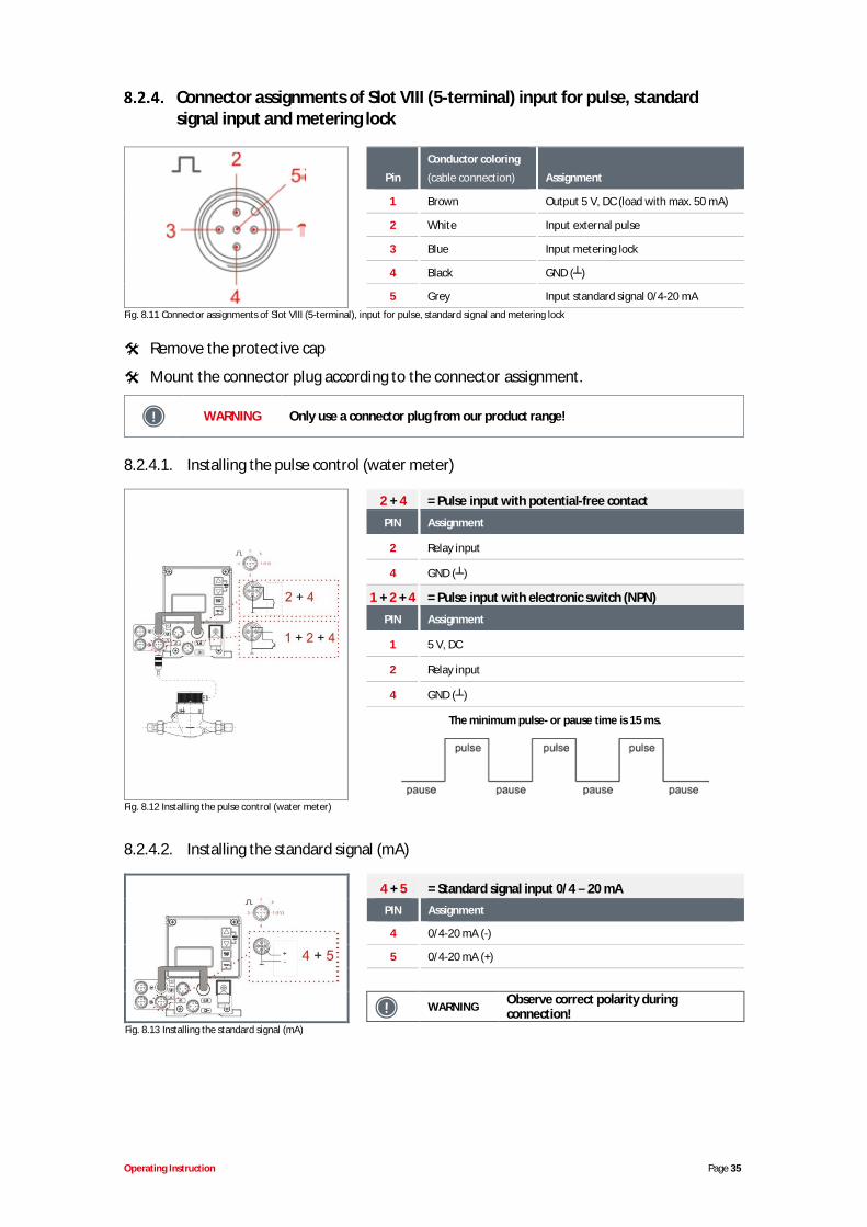
Connector assignments of Slot VIII (5-terminal) input for pulse, standardsignal input and metering lock
Pin
Conductor coloring
(cable connection) Assignment
1 Brown Output 5 V, DC (load with max. 50 mA)
2 White Input external pulse
3 Blue Input metering lock
4 Black GND ( )
5 Grey Input standard signal 0/4-20 mAFig. 8.11 Connector assignments of Slot VIII (5-terminal), input for pulse, standard signal and metering lock
Remove the protective cap
Mount the connector plug according to the connector assignment.
WARNING Only use a connector plug from our product range!
8.2.4.1. Installing the pulse control (water meter)
2 + 4 = Pulse input with potential-free contact
PIN Assignment
2 Relay input
4 GND ( )
1 + 2 + 4 = Pulse input with electronic switch (NPN)
PIN Assignment
1 5 V, DC
2 Relay input
4 GND ( )
The minimum pulse- or pause time is 15 ms.
Fig. 8.12 Installing the pulse control (water meter)
8.2.4.2. Installing the standard signal (mA)
4 + 5 = Standard signal input 0/4 – 20 mAPIN Assignment
4 0/4-20 mA (-)
5 0/4-20 mA (+)
WARNING Observe correct polarity duringconnection!
Fig. 8.13 Installing the standard signal (mA)
Operating Instruction Page 36
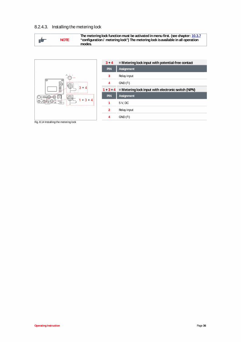
8.2.4.3. Installing the metering lock
NOTEThe metering lock function must be activated in menu first. (see chapter: 10.3.7“configuration / metering lock”) The metering lock is available in all operationmodes.
3 + 4 = Metering lock input with potential-free contact
PIN Assignment
3 Relay input
4 GND ( )
1 + 3 + 4 = Metering lock input with electronic switch (NPN)
PIN Assignment
1 5 V, DC
2 Relay input
4 GND ( )Fig. 8.14 Installing the metering lock
Operating Instruction Page 37
9. STARTUP
NOTE On startup, vent the system as described in chapter 9.3 “Venting the meteringpump“!
CAUTION
If the metering pipe can be shut off, an overflow valve (safety valve) should beinstalled on the pressure side, which opens at the maximum permissible pressurelevel, in order to protect the metering line. This may prevent the metering pipefrom bursting in the event of an operator error.Under unfavourable conditions, the pressure may rise to up to three times thenominal pressure.
NOTE After 24 hours or operation, the metering head screws are to be re-tighteneddiagonally with a torque of approximately 3-4 Nm.
9.1. Switching the pump on/off
Switching on = 2 sec Press START/STOP key (min. 2 sec.).
Switching off = 5 sec Press START/STOP key (min. 5 sec.).
Abb. 9.1 Inbetriebnahme: Ein- Ausschalten der Pumpe
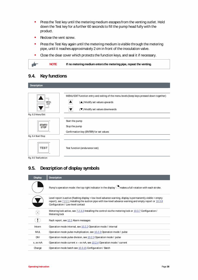
9.2. Setting of the metering output (mechanical)
The metering rate is adjustable by means of mechanicalstroke length setting between 100% and 30% of the pump'srated capacity (reproducible accuracy can no longer beguaranteed below 30%).
The adjustment is made via the stroke adjusting button andcan only be performed while the metering pump is inoperation.
Fig. 9.2 Setting of the metering output (mechanical)
NOTE The capacity of the pump must be calibrated in order to determine the meteringcapacity precisely. (see chapter 10.4 “Calibration”)
9.3. Venting the metering pump
WARNING
Particular caution is required when handling chemical metering media!Metering media may escape which may cause skin irritation, depending on theirproperties. Therefore, before venting, always observe the product datasheet ofthe metering medium to prevent any type of injury!
NOTE
To ensure an optimal suction performance, the stroke length should be set to100% and the maximum stroke frequency.In the event that pump has no suction or insufficient suction, the correctconnection must be checked.
WARNING It is only possible to modify the stroke length setting when the pump is running.
Open the vent screw approximately 1 turn
Hold a suitable collection vessel under the vent connection (see chapter 5, “Setup”, Fig.5.1, Pos. 3).
Operating Instruction Page 38
Press the Test key until the metering medium escapes from the venting outlet. Holddown the Test key for a further 60 seconds to fill the pump head fully with theproduct.
Reclose the vent screw.
Press the Test Key again until the metering medium is visible through the meteringpipe, until it reaches approximately 2 cm in front of the inoculation valve.
Close the clear cover which protects the function keys, and seal it if necessary.
NOTE If no metering medium enters the metering pipe, repeat the venting.
9.4. Key functions
Description
MENU/EXIT function entry and exiting of the menu levels (keep keys pressed down together)
( ) Modify set values upwards
( ) Modify set values downwards
Fig. 9.3 Menu/Exit
Start the pump
Stop the pump
Confirmation key (ENTER) for set values
Fig. 9.4 Start/Stop
Test function (endurance test)
Fig. 9.5 Testfunktion
9.5. Description of display symbols
Display Description
Pump’s operation mode: the top right indicator in the display makes a full rotation with each stroke.
Level report is active (flashing display = low level advance warning, display is permanently visible = emptyreport), see 7.2.2.1 Installing the suction pipe with low-level advance warning and empty report or 10.3.8Configuration / Low-level contact
Metering lock active, see 7.2.3.3 Installing the control via the metering lock or 10.3.7 Configuration /Metering lock
Fault report, see 12.2 Alarm messages
Intern Operation mode internal, see 10.2.2 Operation mode / internal
MUL Operation mode pulse multiplication, see 10.2.3 Operation mode / pulse
DIV Operation mode pulse division, see 10.2.3 Operation mode / pulse
x..xx mA Operation mode current x – xx mA, see 10.2.4 Operation mode / current
Charge Operation mode batch see 10.3.15 Configuration / Batch
Operating Instruction Page 39
Display Description
xxx /min Display strokes / min at Operation mode internal
xx % Display % at Operation mode internal
x.xx l/h Display l/h at Operation mode internal see 10.2.2.2 Display / setting operation mode internal
n = x Display at operation mode pulse, see 10.2.3.2 Display / setting operation mode pulse
xx.x mA Display at operation mode current, see 10.2.4.3 Display / operation mode current
f = xx.x % Display of the current metering frequency in %
OFF Pump is in operating state OFF (must be switched on)
E60+ Dongle box is connected, see 8 Upgrading to Version Chem-Ad® Serie B E60Plus
E60++ Dongle box and OGMPLUS are connected, see 8.2.1.1 Installing the oval gear meter or 10.3.11 Configuration /Oval gear meter
Alarm Alarm operation mode, see 12.2 Alarm messages
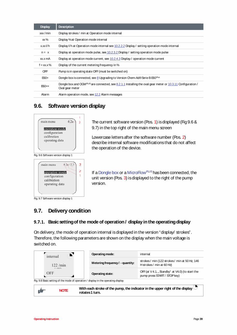
9.6. Software version display
The current software version (Pos. 1) is displayed (Fig 9.6 &9.7) in the top right of the main menu screen
Lowercase letters after the software number (Pos. 2)describe internal software modifications that do not affectthe operation of the device.
Fig. 9.6 Software version display 1
If a Dongle box or a MicroFlowPLUS has been connected, theunit version (Pos. 3) is displayed to the right of the pumpversion.
Fig. 9.7 Software version display 1
9.7. Delivery condition
Basic setting of the mode of operation / display in the operating display
On delivery, the mode of operation internal is displayed in the version “display/ strokes”.Therefore, the following parameters are shown on the display when the main voltage isswitched on.
Operating mode: internal
Metering frequency / - quantity: strokes / min (122 strokes / min at 50 Hz, 146H strokes / min at 60 Hz)
Operating state:OFF (at V 4.1, „Standby“ at V4.0) (to start thepump press START / STOP key)
Fig. 9.8 Basic setting of the mode of operation / display in the operating display
NOTE With each stroke of the pump, the indicator in the upper right of the displayrotates 1 turn.
Operating Instruction Page 40
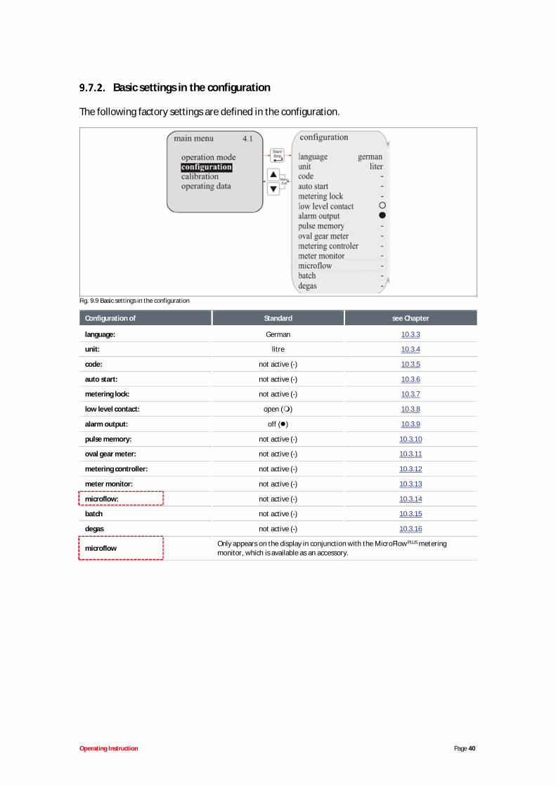
Basic settings in the configuration
The following factory settings are defined in the configuration.
Fig. 9.9 Basic settings in the configuration
Configuration of Standard see Chapter
language: German 10.3.3
unit: litre 10.3.4
code: not active (-) 10.3.5
auto start: not active (-) 10.3.6
metering lock: not active (-) 10.3.7
low level contact: open ( ) 10.3.8
alarm output: off ( ) 10.3.9
pulse memory: not active (-) 10.3.10
oval gear meter: not active (-) 10.3.11
metering controller: not active (-) 10.3.12
meter monitor: not active (-) 10.3.13
microflow: not active (-) 10.3.14
batch not active (-) 10.3.15
degas not active (-) 10.3.16
microflow Only appears on the display in conjunction with the MicroFlowPLUS meteringmonitor, which is available as an accessory.
Operating Instruction Page 41
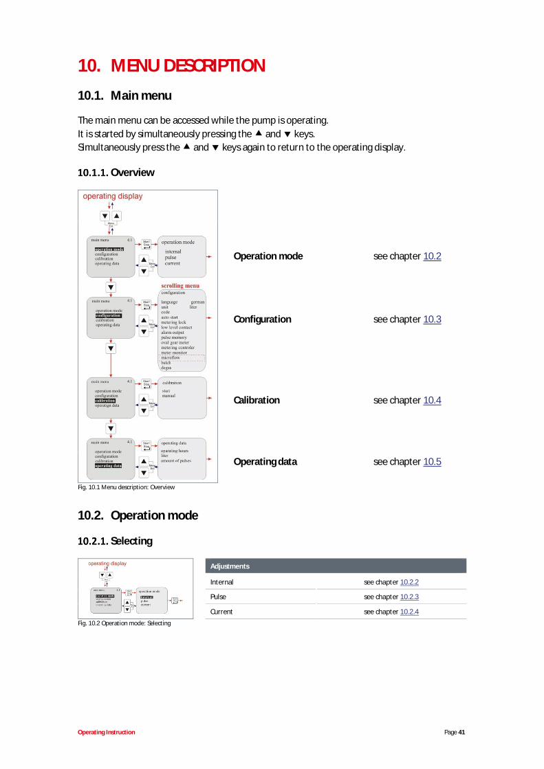
10. MENU DESCRIPTION10.1. Main menu
The main menu can be accessed while the pump is operating.It is started by simultaneously pressing the and keys.Simultaneously press the and keys again to return to the operating display.
Overview
Operation mode see chapter 10.2
Configuration see chapter 10.3
Calibration see chapter 10.4
Operating data see chapter 10.5
Fig. 10.1 Menu description: Overview
10.2. Operation mode
Selecting
Adjustments
Internal see chapter 10.2.2
Pulse see chapter 10.2.3
Current see chapter 10.2.4Fig. 10.2 Operation mode: Selecting
Operating Instruction Page 42
Operation mode / internal
The “internal” operation mode can be used to operate the metering pump without externalsignals.
The following display options can be selected:
Strokes/min The configured metering speed (and thus the metering rate) is displayedin strokes/min. (Default setting)
Percent The configured metering speed (and thus the metering rate) is displayedas a percentage
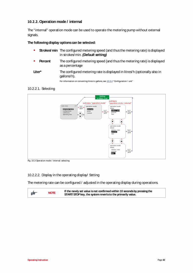
Liter* The configured metering rate is displayed in litres/h (optionally also ingallons/h).For information on converting litres to gallons, see 10.3.4 “Configuration / unit”
10.2.2.1. Selecting
Fig. 10.3 Operation mode / internal: selecting
10.2.2.2. Display in the operating display/ Setting
The metering rate can be configured / adjusted in the operating display during operations.
NOTE If the newly set value is not confirmed within 10 seconds by pressing theSTART/STOP key, the system reverts to the primarily value.
Operating Instruction Page 43
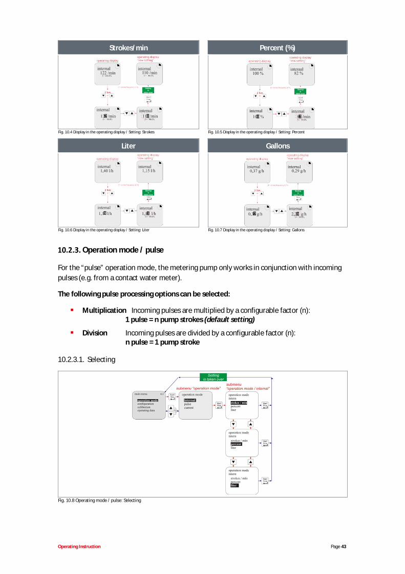
Strokes/min Percent (%)
Fig. 10.4 Display in the operating display / Setting: Strokes Fig. 10.5 Display in the operating display / Setting: Percent
Liter Gallons
Fig. 10.6 Display in the operating display / Setting: Liter Fig. 10.7 Display in the operating display / Setting: Gallons
Operation mode / pulse
For the “pulse” operation mode, the metering pump only works in conjunction with incomingpulses (e.g. from a contact water meter).
The following pulse processing options can be selected:
Multiplication Incoming pulses are multiplied by a configurable factor (n):1 pulse = n pump strokes (default setting)
Division Incoming pulses are divided by a configurable factor (n):n pulse = 1 pump stroke
10.2.3.1. Selecting
Fig. 10.8 Operating mode / pulse: Selecting
Operating Instruction Page 44
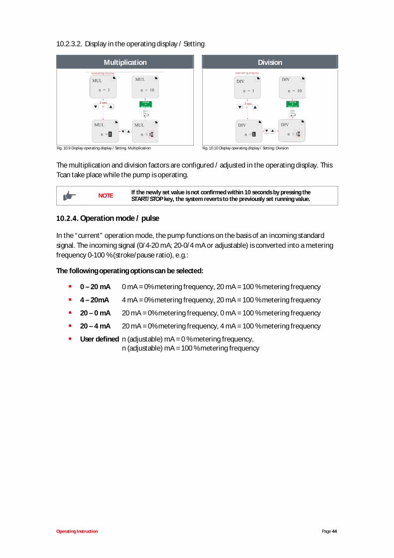
10.2.3.2. Display in the operating display / Setting
Multiplication Division
Fig. 10.9 Display operating display / Setting. Multiplication Fig. 10.10 Display operating display / Setting: Division
The multiplication and division factors are configured / adjusted in the operating display. ThisTcan take place while the pump is operating.
NOTE If the newly set value is not confirmed within 10 seconds by pressing theSTART/STOP key, the system reverts to the previously set running value.
Operation mode / pulse
In the “current” operation mode, the pump functions on the basis of an incoming standardsignal. The incoming signal (0/4-20 mA; 20-0/4 mA or adjustable) is converted into a meteringfrequency 0-100 % (stroke/pause ratio), e.g.:
The following operating options can be selected:
0 – 20 mA 0 mA = 0% metering frequency, 20 mA = 100 % metering frequency
4 – 20mA 4 mA = 0% metering frequency, 20 mA = 100 % metering frequency
20 – 0 mA 20 mA = 0% metering frequency, 0 mA = 100 % metering frequency
20 – 4 mA 20 mA = 0% metering frequency, 4 mA = 100 % metering frequency
User defined n (adjustable) mA = 0 % metering frequency,n (adjustable) mA = 100 % metering frequency
Operating Instruction Page 45
10.2.4.1. Selecting
see chapter 10.2.4.2Fig. 10.11 Operating mode / current (external standard signal): Selecting
10.2.4.2. Setting operation mode / current / user defined
NOTE The difference in the set values must be greater than or equal to 5. (e.g. min 10max 15).
Operating Instruction Page 46
Fig. 10.12 Setting operating mode / current / user defined
10.2.4.3. Display in the operating display
Display POS Description
1 Range of input signal, preset in the menu
2 Actual connected current value
3 Stroke frequency in %
Fig. 10.13 Display in the operating display
10.3. Configuration
Overview
Configuration of: see chapter:
Menu language 10.3.3Units 10.3.4Code entry 10.3.5Startup settings 10.3.6Metering lock 10.3.7Low-level contact 10.3.8Alarm output 10.3.9Pulse memory 10.3.10Oval gear meter 10.3.11Metering controller 10.3.12Metering monitoring 10.3.13MicroFlow 10.3.14
This menu item only appears in conjunctionwith the MicroFlow metering monitor, which isavailable as an accessory, and replaces themenu item “metering monitoring”.Batch 10.3.15Degas 10.3.16
Fig. 10.14 Configuration overview
Operating Instruction Page 47
“Scrolling the display“
The display possesses a "scroll function", i.e. some menu items are onlyshown on the display when the end of the menu is reached on the display.Using the symbols (Pos. 1) or (Pos. 2) on the display, you can seewhich direction you can scroll in.
1 = ( ) scroll the display upwards
2 = ( ) scroll the display downwardsFig. 10.15 Configuration “Scrolling the display”
Configuration / Language
This is used to select the menu language.
10.3.3.1. Selecting
Default setting = German
Fig. 10.16 Configuration / Language: Selecting
Configuration / Unit
If ‘litre’ is selected for the ‘internal’ operation mode (see chapter 10.2.2.2), this can be used tochange the display from litres/h to gallons/ h (1 gallon = 3,785 litres).
Operating Instruction Page 48
10.3.4.1. Selecting
Default setting = litre
Fig. 10.17 Configuration / Unit: Selecting
Configuration / Code
With this setting, a four-digit number combination can be assigned to secure the settingagainst unauthorized adjustment. If ‘code’ has been activated, the four-digit code must beentered before configured values can be amended or the main menu can be accessed.
10.3.5.1. Selecting
- Code query inactive.(Default setting)
Code query active.
see chapter 10.3.5.2
Fig. 10.18 Configuration / Code: Selecting
10.3.5.2. Setting
Fig. 10.19 Configuration / Code: Setting
Operating Instruction Page 49
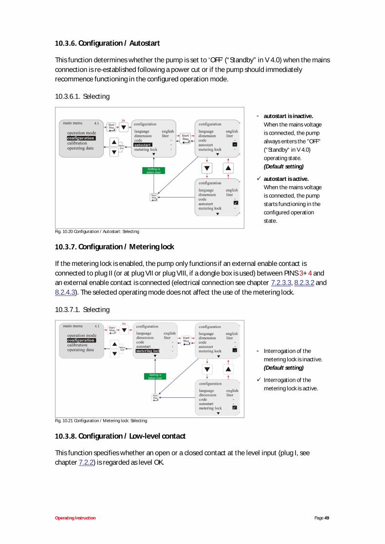
Configuration / Autostart
This function determines whether the pump is set to ‘OFF’ (“Standby” in V 4.0) when the mainsconnection is re-established following a power cut or if the pump should immediatelyrecommence functioning in the configured operation mode.
10.3.6.1. Selecting
- autostart is inactive.When the mains voltageis connected, the pumpalways enters the "OFF"(“Standby“ in V 4.0)operating state.(Default setting)
autostart is active.When the mains voltageis connected, the pumpstarts functioning in theconfigured operationstate.
Fig. 10.20 Configuration / Autostart: Selecting
Configuration / Metering lock
If the metering lock is enabled, the pump only functions if an external enable contact isconnected to plug II (or at plug VII or plug VIII, if a dongle box is used) between PINS 3+ 4 andan external enable contact is connected (electrical connection see chapter 7.2.3.3, 8.2.3.2 and8.2.4.3). The selected operating mode does not affect the use of the metering lock.
10.3.7.1. Selecting
- Interrogation of themetering lock is inactive.(Default setting)
Interrogation of themetering lock is active.
Fig. 10.21 Configuration / Metering lock: Selecting
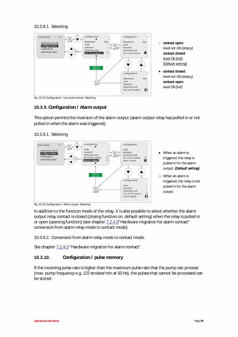
Configuration / Low-level contact
This function specifies whether an open or a closed contact at the level input (plug I, seechapter 7.2.2) is regarded as level OK.
Operating Instruction Page 50
10.3.8.1. Selecting
o contact open:level not OK (empty)contact closed:level OK (full)(Default setting)
contact closed:level not OK (empty)contact open:level OK (full)
Fig. 10.22 Configuration / Low-level-contact: Selecting
Configuration / Alarm output
This option permits the inversion of the alarm output (alarm output relay has pulled in or notpulled in when the alarm was triggered).
10.3.9.1. Selecting
When an alarm istriggered, the relay ispulled in for the alarmoutput. (Default setting)
o When an alarm istriggered, the relay is notpulled in for the alarmoutput.
Fig. 10.23 Configuration / Alarm output: Selecting
In addition to the function mode of the relay, it is also possible to select whether the alarmoutput relay contact is closed (closing function on, default setting) when the relay is pulled inor open (opening function) (see chapter 7.2.4.3“Hardware migration for alarm contact“conversion from alarm relay mode to contact mode).
10.3.9.2. Conversion from alarm relay mode to contact mode.
See chapter 7.2.4.3 “Hardware migration for alarm contact“.
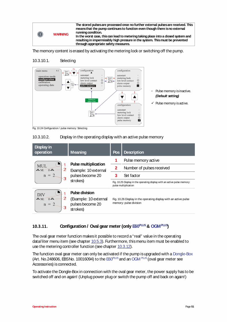
Configuration / pulse memory
If the incoming pulse rate is higher than the maximum pulse rate that the pump can process(max. pump frequency e.g. 122 strokes/min at 50 Hz), the pulses that cannot be processed canbe stored.
Operating Instruction Page 51
WARNING
The stored pulses are processed once no further external pulses are received. Thismeans that the pump continues to function even though there is no externalrunning condition.In the worst case, this can lead to metering taking place into a closed system andresulting in impermissibly high pressure in the system. This must be preventedthrough appropriate safety measures.
The memory content is erased by activating the metering lock or switching off the pump.
10.3.10.1. Selecting
- Pulse memory is inactive.(Default setting)
Pulse memory is active.
Fig. 10.24 Configuration / pulse memory: Selecting
10.3.10.2. Display in the operating display with an active pulse memory
Display inoperation Meaning Pos Description
Pulse multiplicationExample: 10 externalpulses become 20strokes)
1 Pulse memory active
2 Number of pulses received
3 Set factorFig. 10.25 Display in the operating display with an active pulse memory:pulse multiplication
Pulse division(Example: 10 externalpulses become 20strokes)
Fig. 10.26 Display in the operating display with an active pulsememory: pulse division
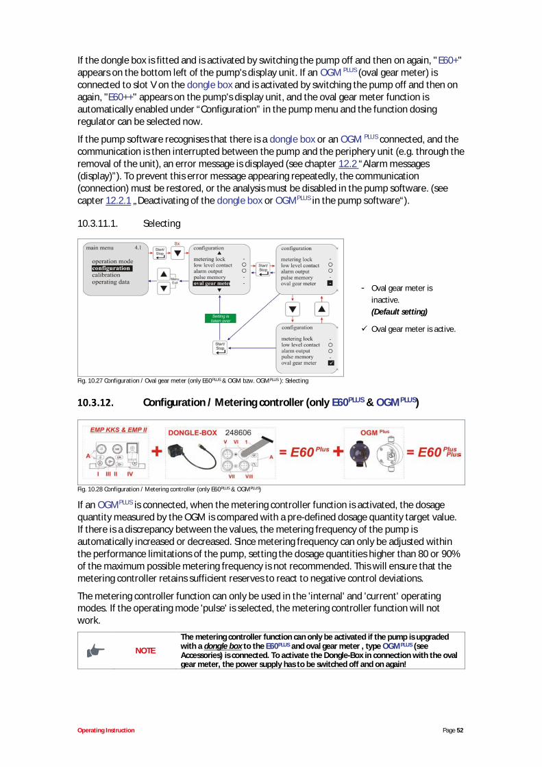
Configuration / Oval gear meter (only E60PLUS & OGMPLUS)
The oval gear meter function makes it possible to record a “real” value in the operatingdata/liter menu item (see chapter 10.5.3). Furthermore, this menu item must be enabled touse the metering controller function (see chapter 10.3.12).
The function oval gear meter can only be activated if the pump is upgraded with a Dongle-Box(Art. No.248606, EBS No. 10016094) to the E60PLUS and an OGM PLUS (oval gear meter seeAccessories) is connected.
To activate the Dongle-Box in connection with the oval gear meter, the power supply has to beswitched off and on again! (Unplug power plug or switch the pump off and back on again!)
Operating Instruction Page 52
If the dongle box is fitted and is activated by switching the pump off and then on again, "E60+"appears on the bottom left of the pump's display unit. If an OGM PLUS (oval gear meter) isconnected to slot V on the dongle box and is activated by switching the pump off and then onagain, "E60++" appears on the pump's display unit, and the oval gear meter function isautomatically enabled under “Configuration” in the pump menu and the function dosingregulator can be selected now.
If the pump software recognises that there is a dongle box or an OGM PLUS connected, and thecommunication is then interrupted between the pump and the periphery unit (e.g. through theremoval of the unit), an error message is displayed (see chapter 12.2 “Alarm messages(display)”). To prevent this error message appearing repeatedly, the communication(connection) must be restored, or the analysis must be disabled in the pump software. (seecapter 12.2.1 „Deactivating of the dongle box or OGMPLUS in the pump software“).
10.3.11.1. Selecting
- Oval gear meter isinactive.(Default setting)
Oval gear meter is active.
Fig. 10.27 Configuration / Oval gear meter (only E60PLUS & OGM bzw. OGMPLUS ): Selecting
Configuration / Metering controller (only E60PLUS & OGMPLUS)
Fig. 10.28 Configuration / Metering controller (only E60PLUS & OGMPLUS)
If an OGMPLUS is connected, when the metering controller function is activated, the dosagequantity measured by the OGM is compared with a pre-defined dosage quantity target value.If there is a discrepancy between the values, the metering frequency of the pump isautomatically increased or decreased. Since metering frequency can only be adjusted withinthe performance limitations of the pump, setting the dosage quantities higher than 80 or 90%of the maximum possible metering frequency is not recommended. This will ensure that themetering controller retains sufficient reserves to react to negative control deviations.
The metering controller function can only be used in the 'internal' and 'current' operatingmodes. If the operating mode 'pulse' is selected, the metering controller function will notwork.
NOTE
The metering controller function can only be activated if the pump is upgradedwith a dongle box to the E60PLUS and oval gear meter , type OGMPLUS (seeAccessories) is connected. To activate the Dongle-Box in connection with the ovalgear meter, the power supply has to be switched off and on again!
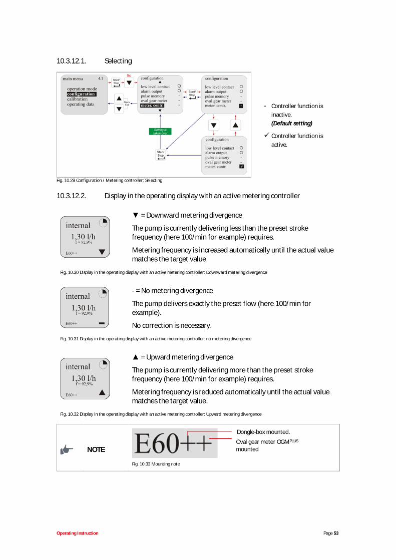
Operating Instruction Page 53
10.3.12.1. Selecting
- Controller function isinactive.(Default setting)
Controller function isactive.
Fig. 10.29 Configuration / Metering controller: Selecting
10.3.12.2. Display in the operating display with an active metering controller
= Downward metering divergence
The pump is currently delivering less than the preset strokefrequency (here 100/min for example) requires.
Metering frequency is increased automatically until the actual valuematches the target value.
Fig. 10.30 Display in the operating display with an active metering controller: Downward metering divergence
- = No metering divergence
The pump delivers exactly the preset flow (here 100/min forexample).
No correction is necessary.
Fig. 10.31 Display in the operating display with an active metering controller: no metering divergence
= Upward metering divergence
The pump is currently delivering more than the preset strokefrequency (here 100/min for example) requires.
Metering frequency is reduced automatically until the actual valuematches the target value.
Fig. 10.32 Display in the operating display with an active metering controller: Upward metering divergence
NOTE
Fig. 10.33 Mounting note
Dongle-box mounted.
Oval gear meter OGMPLUS
mounted
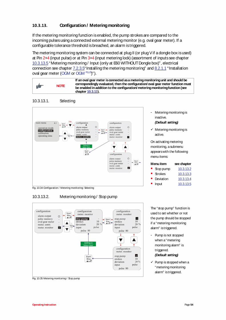
Operating Instruction Page 54
Configuration / Metering monitoring
If the metering monitoring function is enabled, the pump strokes are compared to theincoming pulses using a connected external metering monitor (e.g. oval gear meter). If aconfigurable tolerance threshold is breached, an alarm is triggered.
The metering monitoring system can be connected at plug II (or plug V if a dongle box is used)at Pin 2+4 (input pulse) or at Pin 3+4 (input metering lock) (assortment of inputs see chapter10.3.13.5 “Metering monitoring / Input (only at E60 WITHOUT Dongle box)”, electricalconnection see chapter 7.2.3.5“Installing the metering monitoring” and 8.2.1.1 “Installationoval gear meter (OGM or OGM PLUS)”).
NOTE
If an oval gear meter is connected as a metering monitoring unit and should becorrespondingly evaluated, then the configuration/oval gear meter function mustbe enabled in addition to the configuration/metering monitoring function (seechapter 10.3.11).
10.3.13.1. Selecting
- Metering monitoring isinactive.(Default setting)
Metering monitoring isactive.
On activating meteringmonitoring, a submenuappears with the followingmenu items:
Menu item see chapterStop pump 10.3.13.2Strokes 10.3.13.3Deviation 10.3.13.4Input 10.3.13.5
Fig. 10.34 Configuration / Metering monitoring: Selecting
10.3.13.2. Metering monitoring / Stop pump
The “stop pump” function isused to set whether or notthe pump should be stoppedif a “metering monitoringalarm” is triggered.
- Pump is not stoppedwhen a “meteringmonitoring alarm” istriggered.(Default setting)
Pump is stopped when a“metering monitoringalarm” is triggered.
Fig. 10.35 Metering monitoring / Stop pump
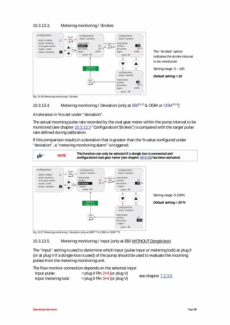
Operating Instruction Page 55
10.3.13.3. Metering monitoring / Strokes
The “strokes” optionindicates the stroke intervalto be monitored.
Setting range: 0 – 100
Default setting = 10
Fig. 10.36 Metering monitoring / Strokes
10.3.13.4. Metering monitoring / Deviation (only at E60PLUS & OGM or OGMPLUS)
A tolerance in % is set under “deviation”.
The actual incoming pulse rate recorded by the oval gear meter within the pump interval to bemonitored (see chapter 10.3.13.3 “Configuration/Strokes”) is compared with the target pulserate defined during calibration.
If this comparison results in a deviation that is greater than the % value configured under“deviation”, a “metering monitoring alarm” is triggered.
NOTE This function can only be selected if a dongle box is connected andconfiguration/oval gear meter (see chapter 10.3.11) has been activated.
Setting range: 0-100%
Default setting = 20 %
Fig. 10.37 Metering monitoring / Deviation (only at E60PLUS & OGM or OGMPLUS)
10.3.13.5. Metering monitoring / Input (only at E60 WITHOUT Dongle box)
The “Input” setting is used to determine which input (pulse input or metering lock) at plug II(or at plug V if a dongle-box is used) of the pump should be used to evaluate the incomingpulses from the metering monitoring unit.
The flow monitor connection depends on the selected input:Input pulse: = plug II Pin 2+4 (or plug V)Input metering lock: = plug II Pin 3+4 (or plug V) see chapter 7.2.3.5.
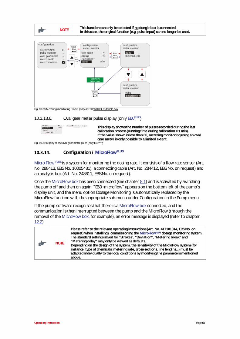
Operating Instruction Page 56
NOTE This function can only be selected if no dongle box is connected.In this case, the original function (e.g. pulse input) can no longer be used.
Fig. 10.38 Metering monitoring / Input (only at E60 WITHOUT dongle box
10.3.13.6. Oval gear meter pulse display (only E60PLUS)
This display shows the number of pulses recorded during the lastcalibration process (running time during calibration = 1 min).If the value shown is less than 60, metering monitoring using an ovalgear meter is only possible to a limited extent.
Fig. 10.39 Display of the oval gear meter pulse (only E60PLUS)
Configuration / MicroFlowPLUS
Micro Flow PLUS is a system for monitoring the dosing rate. It consists of a flow rate sensor (Art.No. 288413, EBS No. 10005481), a connecting cable (Art. No. 284412, EBS No. on request) andan analysis box (Art. No. 248611, EBS No. on request).
Once the MicroFlow box has been connected (see chapter 8.1) and is activated by switchingthe pump off and then on again, "E60+microflow" appears on the bottom left of the pump'sdisplay unit, and the menu option Dosage Monitoring is automatically replaced by theMicroFlow function with the appropriate sub-menu under Configuration in the Pump menu.
If the pump software recognises that there is a MicroFlow box connected, and thecommunication is then interrupted between the pump and the MicroFlow (through theremoval of the MicroFlow box, for example), an error message is displayed (refer to chapter12.2).
NOTE
Please refer to the relevant operating instructions (Art. No. 417101314, EBS No. onrequest) when installing / commissioning the MicroFlowPLUS dosage monitoring system.The standard settings saved for "Strokes", "Deviation", "Metering break" and"Metering delay" may only be viewed as defaults.Depending on the design of the system, the sensitivity of the MicroFlow system (forinstance, type of chemicals, metering rate, cross-sections, line lengths…) must beadapted individually to the local conditions by modifying the parameters mentionedabove.
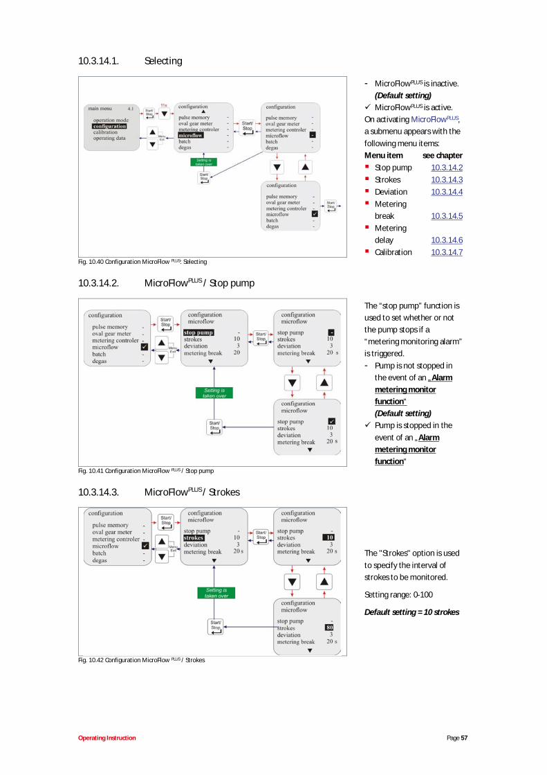
Operating Instruction Page 57
10.3.14.1. Selecting
- MicroFlowPLUS is inactive.(Default setting)MicroFlowPLUS is active.
On activating MicroFlowPLUS,a submenu appears with thefollowing menu items:Menu item see chapter
Stop pump 10.3.14.2Strokes 10.3.14.3Deviation 10.3.14.4Meteringbreak 10.3.14.5Meteringdelay 10.3.14.6Calibration 10.3.14.7
Fig. 10.40 Configuration MicroFlow PLUS: Selecting
10.3.14.2. MicroFlowPLUS / Stop pump
The “stop pump” function isused to set whether or notthe pump stops if a“metering monitoring alarm”is triggered.- Pump is not stopped in
the event of an „Alarmmetering monitorfunction“(Default setting)Pump is stopped in theevent of an „Alarmmetering monitorfunction“
Fig. 10.41 Configuration MicroFlow PLUS / Stop pump
10.3.14.3. MicroFlowPLUS / Strokes
The "Strokes" option is usedto specify the interval ofstrokes to be monitored.
Setting range: 0-100
Default setting = 10 strokes
Fig. 10.42 Configuration MicroFlow PLUS / Strokes
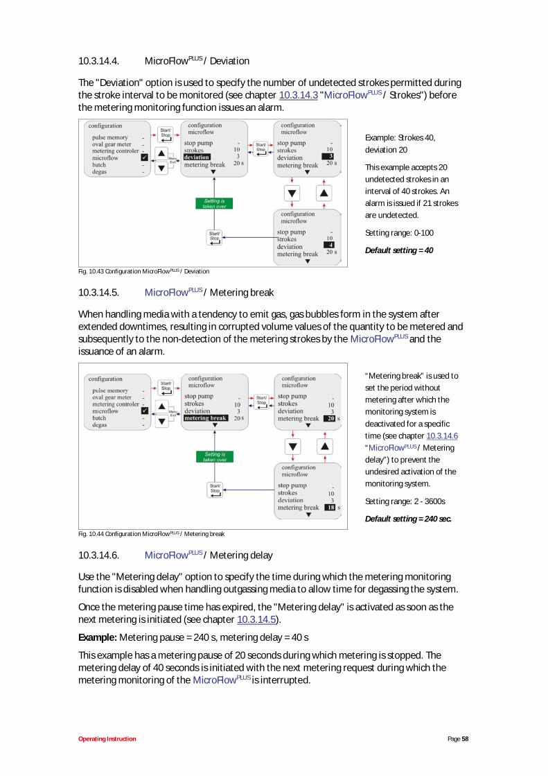
Operating Instruction Page 58
10.3.14.4. MicroFlowPLUS / Deviation
The "Deviation" option is used to specify the number of undetected strokes permitted duringthe stroke interval to be monitored (see chapter 10.3.14.3 "MicroFlowPLUS / Strokes") beforethe metering monitoring function issues an alarm.
Example: Strokes 40,deviation 20
This example accepts 20undetected strokes in aninterval of 40 strokes. Analarm is issued if 21 strokesare undetected.
Setting range: 0-100
Default setting = 40
Fig. 10.43 Configuration MicroFlowPLUS / Deviation
10.3.14.5. MicroFlowPLUS / Metering break
When handling media with a tendency to emit gas, gas bubbles form in the system afterextended downtimes, resulting in corrupted volume values of the quantity to be metered andsubsequently to the non-detection of the metering strokes by the MicroFlowPLUS and theissuance of an alarm.
“Metering break” is used toset the period withoutmetering after which themonitoring system isdeactivated for a specifictime (see chapter 10.3.14.6“MicroFlowPLUS / Meteringdelay”) to prevent theundesired activation of themonitoring system.
Setting range: 2 - 3600s
Default setting = 240 sec.
Fig. 10.44 Configuration MicroFlowPLUS / Metering break
10.3.14.6. MicroFlowPLUS / Metering delay
Use the "Metering delay" option to specify the time during which the metering monitoringfunction is disabled when handling outgassing media to allow time for degassing the system.
Once the metering pause time has expired, the "Metering delay" is activated as soon as thenext metering is initiated (see chapter 10.3.14.5).
Example: Metering pause = 240 s, metering delay = 40 s
This example has a metering pause of 20 seconds during which metering is stopped. Themetering delay of 40 seconds is initiated with the next metering request during which themetering monitoring of the MicroFlowPLUS is interrupted.
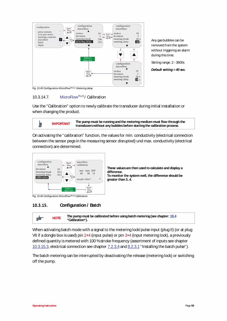
Operating Instruction Page 59
Any gas bubbles can beremoved from the systemwithout triggering an alarmduring this time.
Setting range: 2 - 3600s
Default setting = 40 sec.
Fig. 10.45 Configuration MicroFlowPLUS / Metering delay
10.3.14.7. MicroFlowPLUS / Calibration
Use the "Calibration" option to newly calibrate the transducer during initial installation orwhen changing the product.
IMPORTANT The pump must be running and the metering medium must flow through thetransducers without any bubbles before starting the calibration process.
On activating the “calibration” function, the values for min. conductivity (electrical connectionbetween the sensor pegs in the measuring sensor disrupted) und max. conductivity (electricalconnection) are determined.
These values are then used to calculate and display adifference.To monitor the system well, the difference should begreater than 3..4.
Fig. 10.46 Configuration MicroFlowPLUS /Calibration
Configuration / Batch
NOTE The pump must be calibrated before using batch metering (see chapter: 10.4“Calibration“).
When activating batch mode with a signal to the metering lock/pulse input (plug II) (or at plugVII if a dongle box is used) pin 2+4 (input pulse) or pin 3+4 (input metering lock), a previouslydefined quantity is metered with 100 % stroke frequency (assortment of inputs see chapter10.3.15.3, electrical connection see chapter 7.2.3.4 and 8.2.3.1 “Installing the batch pulse“).
The batch metering can be interrupted by deactivating the release (metering lock) or switchingoff the pump.
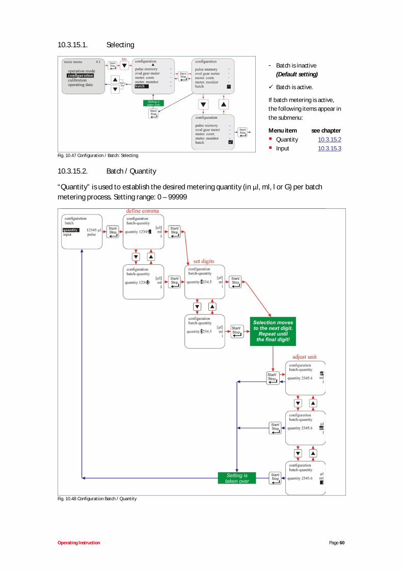
Operating Instruction Page 60
10.3.15.1. Selecting
- Batch is inactive(Default setting)
Batch is active.
If batch metering is active,the following items appear inthe submenu:
Menu item see chapterQuantity 10.3.15.2Input 10.3.15.3
Fig. 10.47 Configuration / Batch: Selecting
10.3.15.2. Batch / Quantity
“Quantity” is used to establish the desired metering quantity (in l, ml, l or G) per batchmetering process. Setting range: 0 – 99999
Fig. 10.48 Configuration Batch / Quantity
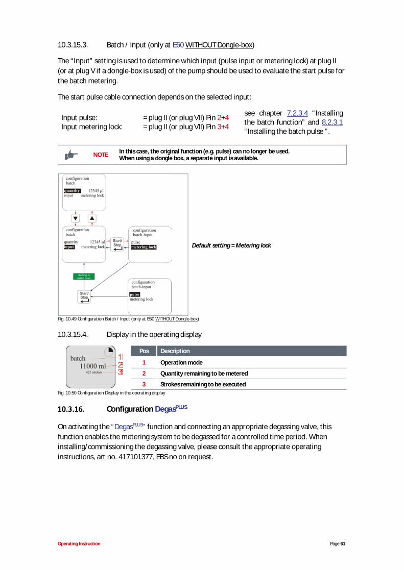
Operating Instruction Page 61
10.3.15.3. Batch / Input (only at E60 WITHOUT Dongle-box)
The “Input” setting is used to determine which input (pulse input or metering lock) at plug II(or at plug V if a dongle-box is used) of the pump should be used to evaluate the start pulse forthe batch metering.
The start pulse cable connection depends on the selected input:
Input pulse: = plug II (or plug VII) Pin 2+4Input metering lock: = plug II (or plug VII) Pin 3+4
see chapter 7.2.3.4 “Installingthe batch function” and 8.2.3.1“Installing the batch pulse ”.
NOTE In this case, the original function (e.g. pulse) can no longer be used.When using a dongle box, a separate input is available.
Default setting = Metering lock
Fig. 10.49 Configuration Batch / Input (only at E60 WITHOUT Dongle-box)
10.3.15.4. Display in the operating display
Pos Description
1 Operation mode
2 Quantity remaining to be metered
3 Strokes remaining to be executedFig. 10.50 Configuration Display in the operating display
Configuration DegasPLUS
On activating the “DegasPLUS” function and connecting an appropriate degassing valve, thisfunction enables the metering system to be degassed for a controlled time period. Wheninstalling/commissioning the degassing valve, please consult the appropriate operatinginstructions, art no. 417101377, EBS no on request.
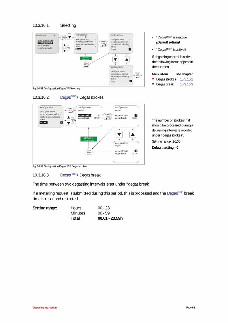
Operating Instruction Page 62
10.3.16.1. Selecting
- “DegasPLUS“ is inactive(Default setting)
“DegasPLUS“ is activeIf
If degassing control is active,the following items appear inthe submenu:
Menu item see chapterDegas strokes 10.3.16.2Degas break 10.3.16.3
Fig. 10.51 Configuration DegasPLUS Selecting
10.3.16.2. DegasPLUS / Degas strokes
The number of strokes thatshould be processed during adegassing interval is recodedunder “degas strokes”.
Setting range: 1-100
Default setting = 0
Fig. 10.52 Configuration DegasPLUS / Degas strokes
10.3.16.3. DegasPLUS / Degas break
The time between two degassing intervals is set under “degas break”.
If a metering request is submitted during this period, this is processed and the DegasPLUS breaktime is reset and restarted.
Setting range: Hours 00 - 23Minutes 00 - 59Total 00.01 - 23.59h
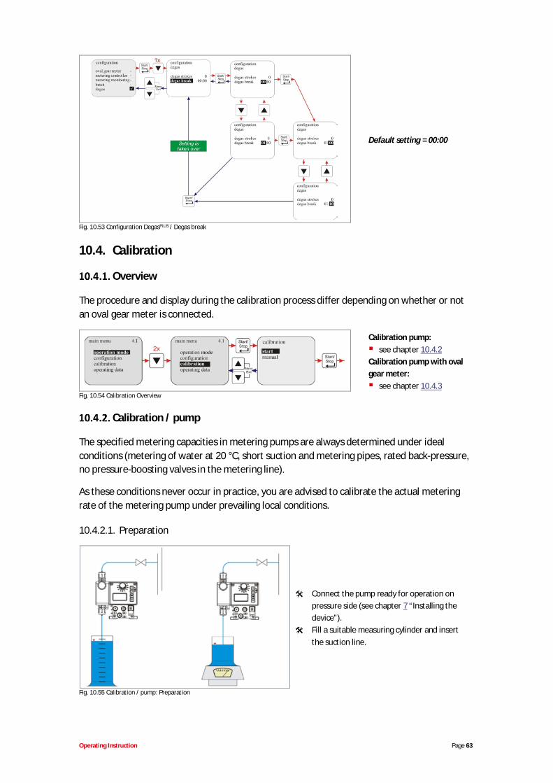
Operating Instruction Page 63
Default setting = 00:00
Fig. 10.53 Configuration DegasPLUS / Degas break
10.4. Calibration
Overview
The procedure and display during the calibration process differ depending on whether or notan oval gear meter is connected.
Calibration pump:see chapter 10.4.2
Calibration pump with ovalgear meter:
see chapter 10.4.3Fig. 10.54 Calibration Overview
Calibration / pump
The specified metering capacities in metering pumps are always determined under idealconditions (metering of water at 20 °C, short suction and metering pipes, rated back-pressure,no pressure-boosting valves in the metering line).
As these conditions never occur in practice, you are advised to calibrate the actual meteringrate of the metering pump under prevailing local conditions.
10.4.2.1. Preparation
Connect the pump ready for operation onpressure side (see chapter 7 “Installing thedevice”).Fill a suitable measuring cylinder and insertthe suction line.
Fig. 10.55 Calibration / pump: Preparation
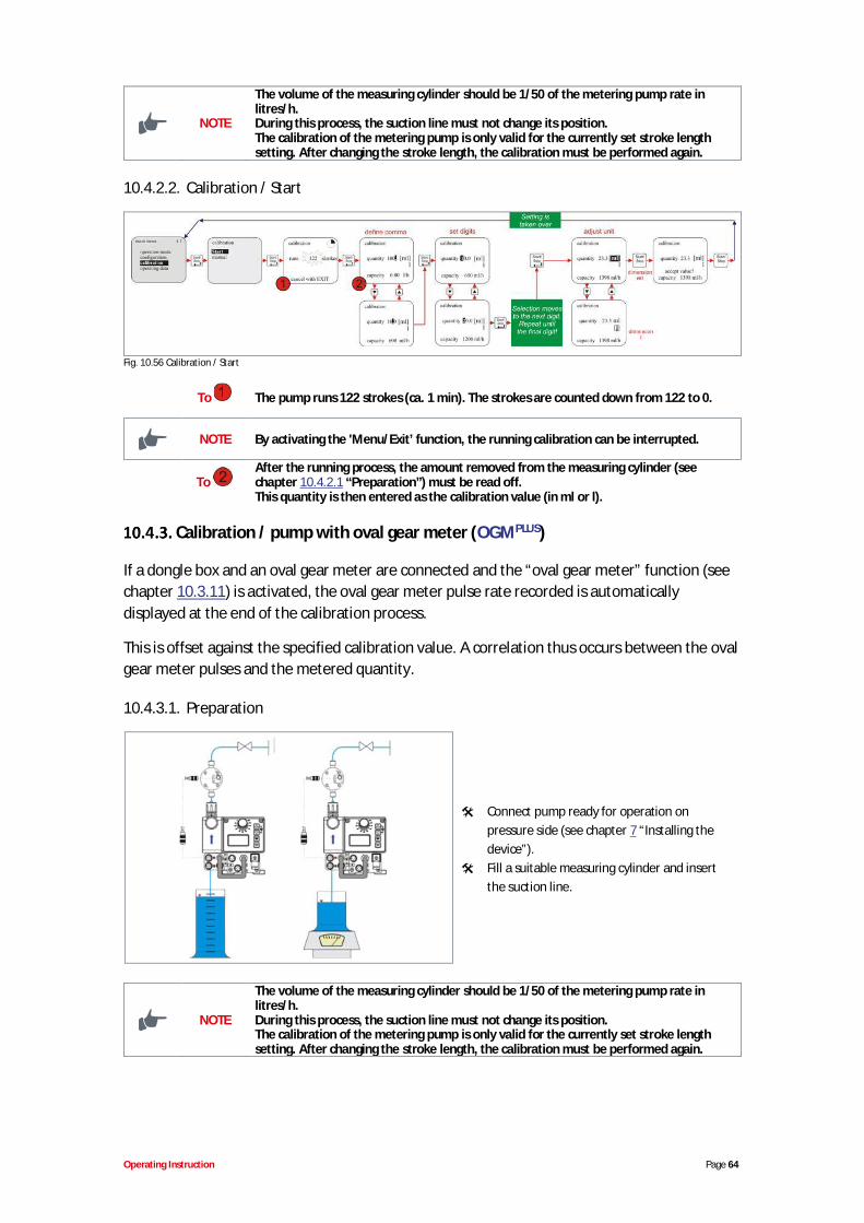
Operating Instruction Page 64
NOTE
The volume of the measuring cylinder should be 1/50 of the metering pump rate inlitres/h.During this process, the suction line must not change its position.The calibration of the metering pump is only valid for the currently set stroke lengthsetting. After changing the stroke length, the calibration must be performed again.
10.4.2.2. Calibration / Start
Fig. 10.56 Calibration / Start
To The pump runs 122 strokes (ca. 1 min). The strokes are counted down from 122 to 0.
NOTE By activating the 'Menu/Exit’ function, the running calibration can be interrupted.
ToAfter the running process, the amount removed from the measuring cylinder (seechapter 10.4.2.1 “Preparation”) must be read off.This quantity is then entered as the calibration value (in ml or l).
Calibration / pump with oval gear meter (OGMPLUS)
If a dongle box and an oval gear meter are connected and the “oval gear meter” function (seechapter 10.3.11) is activated, the oval gear meter pulse rate recorded is automaticallydisplayed at the end of the calibration process.
This is offset against the specified calibration value. A correlation thus occurs between the ovalgear meter pulses and the metered quantity.
10.4.3.1. Preparation
Connect pump ready for operation onpressure side (see chapter 7 “Installing thedevice”).Fill a suitable measuring cylinder and insertthe suction line.
NOTE
The volume of the measuring cylinder should be 1/50 of the metering pump rate inlitres/h.During this process, the suction line must not change its position.The calibration of the metering pump is only valid for the currently set stroke lengthsetting. After changing the stroke length, the calibration must be performed again.
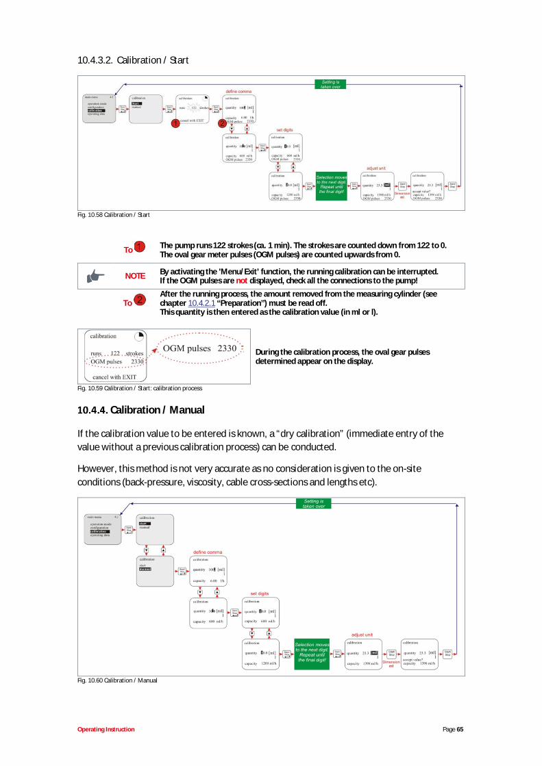
Operating Instruction Page 65
10.4.3.2. Calibration / Start
Fig. 10.58 Calibration / Start
To The pump runs 122 strokes (ca. 1 min). The strokes are counted down from 122 to 0.The oval gear meter pulses (OGM pulses) are counted upwards from 0.
NOTE By activating the 'Menu/Exit’ function, the running calibration can be interrupted.If the OGM pulses are not displayed, check all the connections to the pump!
ToAfter the running process, the amount removed from the measuring cylinder (seechapter 10.4.2.1 “Preparation”) must be read off.This quantity is then entered as the calibration value (in ml or l).
During the calibration process, the oval gear pulsesdetermined appear on the display.
Fig. 10.59 Calibration / Start: calibration process
Calibration / Manual
If the calibration value to be entered is known, a “dry calibration” (immediate entry of thevalue without a previous calibration process) can be conducted.
However, this method is not very accurate as no consideration is given to the on-siteconditions (back-pressure, viscosity, cable cross-sections and lengths etc).
Fig. 10.60 Calibration / Manual
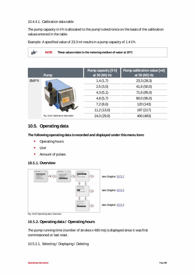
Operating Instruction Page 66
10.4.4.1. Calibration data table
The pump capacity in l/h is allocated to the pump’s electronics on the basis of the calibrationvalues entered in the table.
Example: A specified value of 23.3 ml results in a pump capacity of 1.4 l/h.
NOTE These values relate to the metering medium of water at 20°C
PumpPump capacity [l/h]
at 50 (60) HzPump calibration value [ml]
at 50 (60) HzEMP II
Fig. 10.61 Calibration data table
1,4 (1,7) 23,3 (28,3)
2,5 (3,0) 41,6 (50,0)
4,3 (5,1) 71,6 (85,0)
4,8 (5,7) 80,0 (95,0)
7,2 (8,6) 120 (143)
11,2 (13,0) 187 (217)
24,0 (29,0) 400 (483)
10.5. Operating data
The following operating data is recorded and displayed under this menu item:
Operating hours
Liter
Amount of pulses
Overview
see chapter 10.5.2
see chapter 10.5.3
see chapter 10.5.4
Fig. 10.62 Operating data: Overview
Operating data / Operating hours
The pump running time (number of strokes x 480 ms) is displayed since it was firstcommissioned or last reset.
10.5.2.1. Selecting / Displaying / Deleting
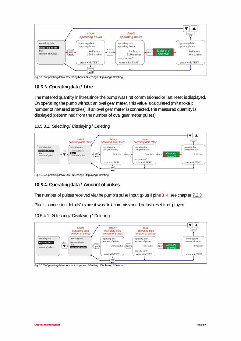
Operating Instruction Page 67
Fig. 10.63 Operating data / Operating hours: Selecting / Displaying / Deleting
Operating data / Litre
The metered quantity in litres since the pump was first commissioned or last reset is displayed.On operating the pump without an oval gear meter, this value is calculated (ml/stroke xnumber of metered strokes). If an oval gear meter is connected, the measured quantity isdisplayed (determined from the number of oval gear meter pulses).
10.5.3.1. Selecting / Displaying / Deleting
Fig. 10.64 Operating data / litre: Selecting / Displaying / Deleting
Operating data / Amount of pulses
The number of pulses received via the pump’s pulse input (plus II pins 3+4, see chapter 7.2.3
Plug II connection details”) since it was first commissioned or last reset is displayed.
10.5.4.1. Selecting / Displaying / Deleting
Fig. 10.65 Operating data / Amount of pulses: Selecting / Displaying / Deleting
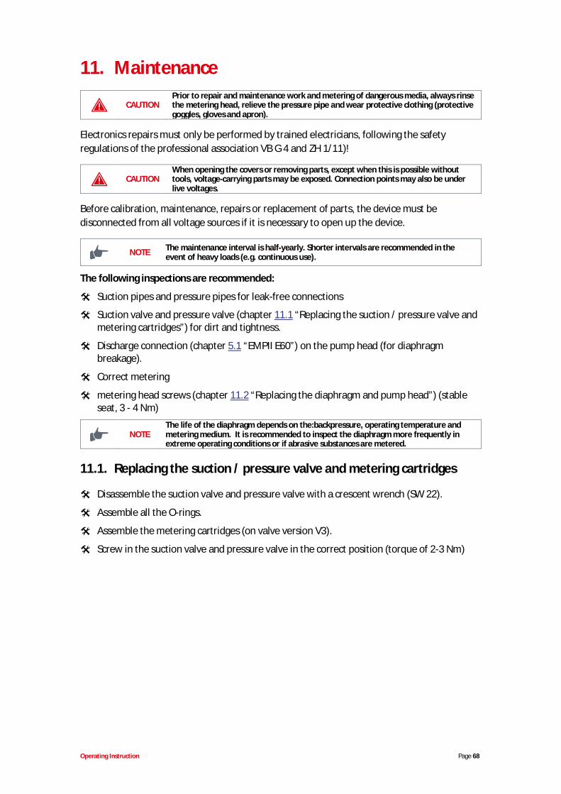
Operating Instruction Page 68
11. Maintenance
CAUTIONPrior to repair and maintenance work and metering of dangerous media, always rinsethe metering head, relieve the pressure pipe and wear protective clothing (protectivegoggles, gloves and apron).
Electronics repairs must only be performed by trained electricians, following the safetyregulations of the professional association VB G 4 and ZH 1/11)!
CAUTIONWhen opening the covers or removing parts, except when this is possible withouttools, voltage-carrying parts may be exposed. Connection points may also be underlive voltages.
Before calibration, maintenance, repairs or replacement of parts, the device must bedisconnected from all voltage sources if it is necessary to open up the device.
NOTE The maintenance interval is half-yearly. Shorter intervals are recommended in theevent of heavy loads (e.g. continuous use).
The following inspections are recommended:
Suction pipes and pressure pipes for leak-free connections
Suction valve and pressure valve (chapter 11.1 “Replacing the suction / pressure valve andmetering cartridges”) for dirt and tightness.
Discharge connection (chapter 5.1 “EMPII E60”) on the pump head (for diaphragmbreakage).
Correct metering
metering head screws (chapter 11.2 “Replacing the diaphragm and pump head”) (stableseat, 3 - 4 Nm)
NOTEThe life of the diaphragm depends on the:backpressure, operating temperature andmetering medium. It is recommended to inspect the diaphragm more frequently inextreme operating conditions or if abrasive substances are metered.
11.1. Replacing the suction / pressure valve and metering cartridges
Disassemble the suction valve and pressure valve with a crescent wrench (SW 22).
Assemble all the O-rings.
Assemble the metering cartridges (on valve version V3).
Screw in the suction valve and pressure valve in the correct position (torque of 2-3 Nm)
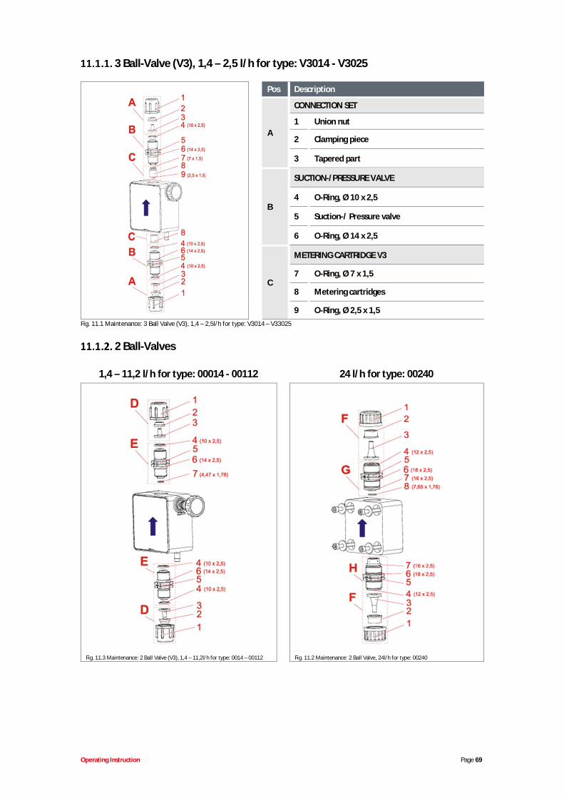
Operating Instruction Page 69
3 Ball-Valve (V3), 1,4 – 2,5 l/h for type: V3014 - V3025
Pos Description
A
CONNECTION SET
1 Union nut
2 Clamping piece
3 Tapered part
B
SUCTION-/PRESSURE VALVE
4 O-Ring, Ø 10 x 2,5
5 Suction-/ Pressure valve
6 O-Ring, Ø 14 x 2,5
C
METERING CARTRIDGE V3
7 O-Ring, Ø 7 x 1,5
8 Metering cartridges
9 O-Ring, Ø 2,5 x 1,5Fig. 11.1 Maintenance: 3 Ball Valve (V3), 1,4 – 2,5l/h for type: V3014 – V33025
2 Ball-Valves
1,4 – 11,2 l/h for type: 00014 - 00112 24 l/h for type: 00240
Fig. 11.3 Maintenance: 2 Ball Valve (V3), 1,4 – 11,2l/h for type: 0014 – 00112 Fig. 11.2 Maintenance: 2 Ball Valve, 24l/h for type: 00240
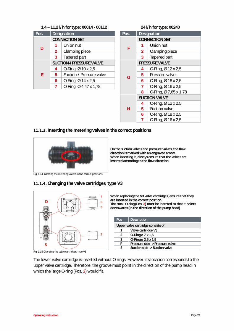
Operating Instruction Page 70
1,4 – 11,2 l/h for type: 00014 - 00112 24 l/h for type: 00240Pos. Designation Pos. Designation
D
CONNECTION SET
F
CONNECTION SET1 Union nut 1 Union nut2 Clamping piece 2 Clamping piece3 Tapered part 3 Tapered part
E
SUCTION-/PRESSURE VALVE
G
PRESSURE VALVE4 O-Ring, Ø 10 x 2,5 4 O-Ring, Ø 12 x 2,55 Suction-/ Pressure valve 5 Pressure valve6 O-Ring, Ø 14 x 2,5 6 O-Ring, Ø 18 x 2,57 O-Ring, Ø 4,47 x 1,78 7 O-Ring, Ø 16 x 2,5
8 O-Ring, Ø 7,65 x 1,78
H
SUCTION VALVE4 O-Ring, Ø 12 x 2,55 Suction valve6 O-Ring, Ø 18 x 2,57 O-Ring, Ø 16 x 2,5
Inserting the metering valves in the correct positions
On the suction valves and pressure valves, the flowdirection is marked with an engraved arrow.When inserting it, always ensure that the valves areinserted according to the flow direction!
Fig. 11.4 Inserting the metering valves in the correct positions
Changing the valve cartridges, type V3
When replacing the V3 valve cartridges, ensure that theyare inserted in the correct position.The small O-ring (Pos. 3) must be inserted so that it pointsdownwards (in the direction of the pump head)
Pos Description
Upper valve cartridge consists of:1 Valve cartridge V32 O-Ring ø 7 x 1,53 O-Ring ø 2,5 x 1,5P Pressure side -> Pressure valveS Suction side -> Suction valve
Fig. 11.5 Changing the valve cartridges, type V3
The lower valve cartridge is inserted without O-rings. However, its location corresponds to theupper valve cartridge. Therefore, the groove must point in the direction of the pump head inwhich the large O-ring (Pos. 2) would fit.
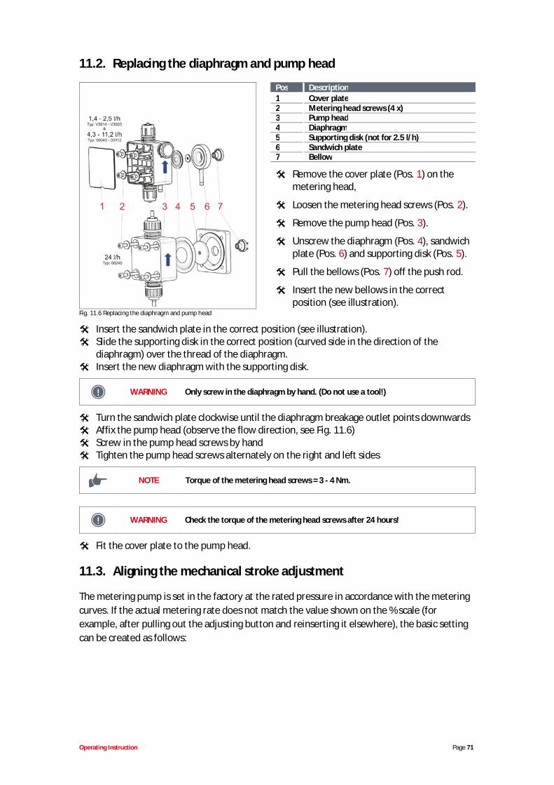
Operating Instruction Page 71
11.2. Replacing the diaphragm and pump head
Pos Description1 Cover plate2 Metering head screws (4 x)3 Pump head4 Diaphragm5 Supporting disk (not for 2.5 l/h)6 Sandwich plate7 Bellow
Remove the cover plate (Pos. 1) on themetering head,
Loosen the metering head screws (Pos. 2).
Remove the pump head (Pos. 3).
Unscrew the diaphragm (Pos. 4), sandwichplate (Pos. 6) and supporting disk (Pos. 5).
Pull the bellows (Pos. 7) off the push rod.
Insert the new bellows in the correctposition (see illustration).
Fig. 11.6 Replacing the diaphragm and pump head
Insert the sandwich plate in the correct position (see illustration).Slide the supporting disk in the correct position (curved side in the direction of thediaphragm) over the thread of the diaphragm.Insert the new diaphragm with the supporting disk.
WARNING Only screw in the diaphragm by hand. (Do not use a tool!)
Turn the sandwich plate clockwise until the diaphragm breakage outlet points downwardsAffix the pump head (observe the flow direction, see Fig. 11.6)Screw in the pump head screws by handTighten the pump head screws alternately on the right and left sides
NOTE Torque of the metering head screws = 3 - 4 Nm.
WARNING Check the torque of the metering head screws after 24 hours!
Fit the cover plate to the pump head.
11.3. Aligning the mechanical stroke adjustment
The metering pump is set in the factory at the rated pressure in accordance with the meteringcurves. If the actual metering rate does not match the value shown on the % scale (forexample, after pulling out the adjusting button and reinserting it elsewhere), the basic settingcan be created as follows:
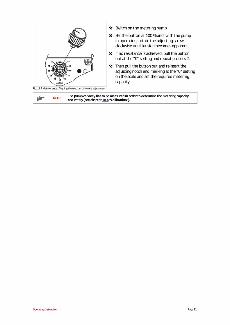
Operating Instruction Page 72
Switch on the metering pump
Set the button at 100 % and, with the pumpin operation, rotate the adjusting screwclockwise until tension becomes apparent.
If no resistance is achieved, pull the buttonout at the "0" setting and repeat process 2.
Then pull the button out and reinsert theadjusting notch and marking at the "0" settingon the scale and set the required meteringcapacity.
Fig. 11.7 Maintenance: Aligning the mechanical stroke adjustment
NOTE The pump capacity has to be measured in order to determine the metering capacityaccurately (see chapter 10.4 “Calibration“).
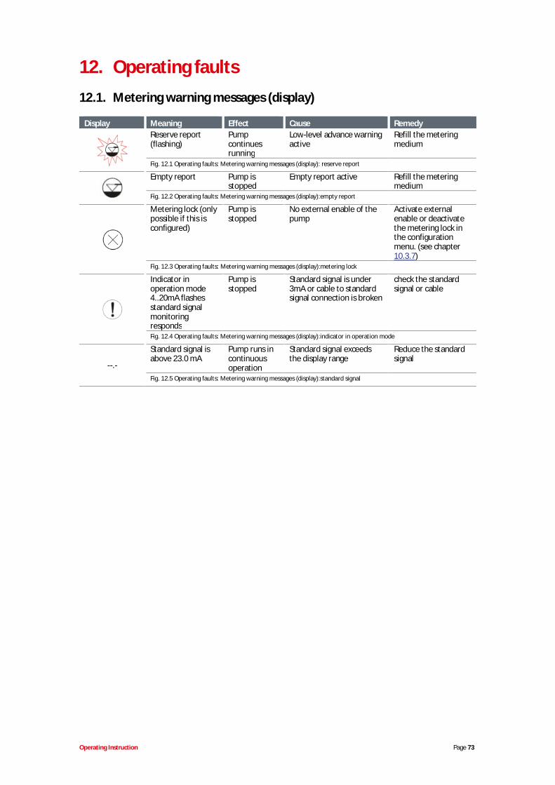
Operating Instruction Page 73
12. Operating faults12.1. Metering warning messages (display)
Display Meaning Effect Cause RemedyReserve report(flashing)
Pumpcontinuesrunning
Low-level advance warningactive
Refill the meteringmedium
Fig. 12.1 Operating faults: Metering warning messages (display): reserve report
Empty report Pump isstopped
Empty report active Refill the meteringmedium
Fig. 12.2 Operating faults: Metering warning messages (display):empty report
Metering lock (onlypossible if this isconfigured)
Pump isstopped
No external enable of thepump
Activate externalenable or deactivatethe metering lock inthe configurationmenu. (see chapter10.3.7)
Fig. 12.3 Operating faults: Metering warning messages (display):metering lock
Indicator inoperation mode4..20mA flashesstandard signalmonitoringresponds
Pump isstopped
Standard signal is under3mA or cable to standardsignal connection is broken
check the standardsignal or cable
Fig. 12.4 Operating faults: Metering warning messages (display):indicator in operation mode
--.-
Standard signal isabove 23.0 mA
Pump runs incontinuousoperation
Standard signal exceedsthe display range
Reduce the standardsignal
Fig. 12.5 Operating faults: Metering warning messages (display):standard signal
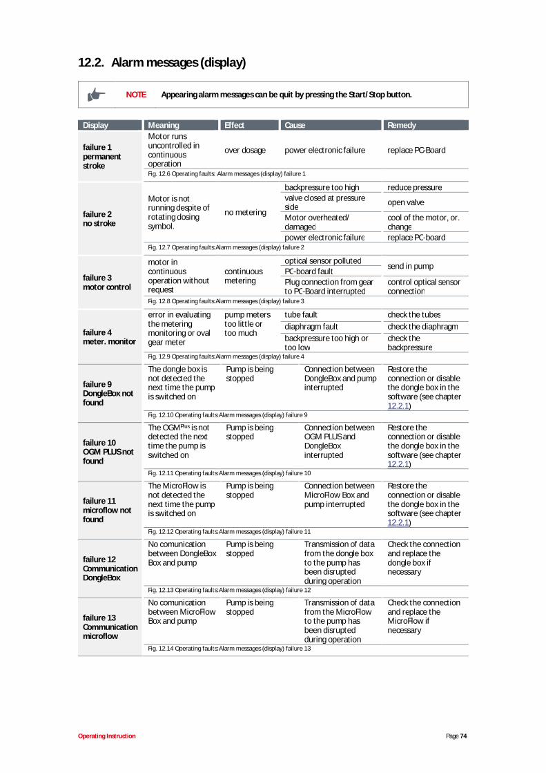
Operating Instruction Page 74
12.2. Alarm messages (display)
NOTE Appearing alarm messages can be quit by pressing the Start/Stop button.
Display Meaning Effect Cause Remedy
failure 1permanentstroke
Motor runsuncontrolled incontinuousoperation
over dosage power electronic failure replace PC-Board
Fig. 12.6 Operating faults: Alarm messages (display) failure 1
failure 2no stroke
Motor is notrunning despite ofrotating dosingsymbol.
no metering
backpressure too high reduce pressurevalve closed at pressureside open valve
Motor overheated/damaged
cool of the motor, or.change
power electronic failure replace PC-boardFig. 12.7 Operating faults:Alarm messages (display) failure 2
failure 3motor control
motor incontinuousoperation withoutrequest
continuousmetering
optical sensor polluted send in pumpPC-board faultPlug connection from gearto PC-Board interrupted
control optical sensorconnection
Fig. 12.8 Operating faults:Alarm messages (display) failure 3
failure 4meter. monitor
error in evaluatingthe meteringmonitoring or ovalgear meter
pump meterstoo little ortoo much
tube fault check the tubesdiaphragm fault check the diaphragmbackpressure too high ortoo low
check thebackpressure
Fig. 12.9 Operating faults:Alarm messages (display) failure 4
failure 9DongleBox notfound
The dongle box isnot detected thenext time the pumpis switched on
Pump is beingstopped
Connection betweenDongleBox and pumpinterrupted
Restore theconnection or disablethe dongle box in thesoftware (see chapter12.2.1)
Fig. 12.10 Operating faults:Alarm messages (display) failure 9
failure 10OGM PLUS notfound
The OGMPlus is notdetected the nexttime the pump isswitched on
Pump is beingstopped
Connection betweenOGM PLUS andDongleBoxinterrupted
Restore theconnection or disablethe dongle box in thesoftware (see chapter12.2.1)
Fig. 12.11 Operating faults:Alarm messages (display) failure 10
failure 11microflow notfound
The MicroFlow isnot detected thenext time the pumpis switched on
Pump is beingstopped
Connection betweenMicroFlow Box andpump interrupted
Restore theconnection or disablethe dongle box in thesoftware (see chapter12.2.1)
Fig. 12.12 Operating faults:Alarm messages (display) failure 11
failure 12CommunicationDongleBox
No comunicationbetween DongleBoxBox and pump
Pump is beingstopped
Transmission of datafrom the dongle boxto the pump hasbeen disruptedduring operation
Check the connectionand replace thedongle box ifnecessary
Fig. 12.13 Operating faults:Alarm messages (display) failure 12
failure 13Communicationmicroflow
No comunicationbetween MicroFlowBox and pump
Pump is beingstopped
Transmission of datafrom the MicroFlowto the pump hasbeen disruptedduring operation
Check the connectionand replace theMicroFlow ifnecessary
Fig. 12.14 Operating faults:Alarm messages (display) failure 13
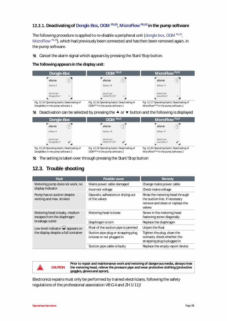
Operating Instruction Page 75
Deactivating of Dongle Box, OGM PLUS, MicroFlow PLUS in the pump software
The following procedure is applied to re-disable a peripheral unit (dongle box, OGM PLUS,MicroFlow PLUS), which had previously been connected and has then been removed again, inthe pump software.
Cancel the alarm signal which appears by pressing the Start/Stop button.
The following appears in the display unit:
Dongle-Box OGM PLUS MicroFlow PLUS
Fig. 12.15 Operating faults: Deactivating ofDongleBox in the pump software 1
Fig. 12.16 Operating faults: Deactivating ofOGMPLUS in the pump software 1
Fig. 12.17 Operating faults: Deactivating ofMicroFlowPLUS in the pump software 1
Deactivation can be selected by pressing the or button and the following is displayed
Dongle-Box OGM PLUS MicroFlow PLUS
Fig. 12.18 Operating faults: Deactivating ofDongleBox in the pump software 2
Fig. 12.19 Operating faults: Deactivating ofOGMPLUS in the pump software 2
Fig. 12.20 Operating faults: Deactivating ofMicroFlowPLUS in the pump software 2
The setting is taken over through pressing the Start/Stop button
12.3. Trouble shooting
Fault Possible cause RemedyMetering pump does not work, nodisplay indicator
Mains power cable damaged Change mains power cableIncorrect voltage Check mains voltage
Pump has no suction despiteventing and max. strokes
Deposits, adhesions or drying-outof the valves
Rinse the metering head throughthe suction line, if necessaryremove and clean or replace thevalves
Metering head is leaky, mediumescapes from the diaphragmbreakage outlet
Metering head is loose Screw in the metering headfastening screw diagonally
Diaphragm is torn Replace the diaphragm
Low-level indicator appears onthe display despite a full container
Float of the suction pipe is jammed Unjam the floatSuction pipe plug or strapping plugis loose or not plugged in
Tighten the plug, clean thecontacts, check whether thestrapping plug is plugged in
Suction pipe cable is faulty Replace the empty report device
CAUTIONPrior to repair and maintenance work and metering of dangerous media, always rinsethe metering head, relieve the pressure pipe and wear protective clothing (protectivegoggles, gloves and apron).
Electronics repairs must only be performed by trained electricians, following the safetyregulations of the professional association VB G 4 and ZH 1/11)!

Operating Instruction Page 76
CAUTIONWhen opening the covers or removing parts, except when this is possible withouttools, voltage-carrying parts may be exposed. Connection points may also be underlive voltages.
Before calibration, maintenance, repairs or replacement of parts, the device must bedisconnected from all voltage sources if it is necessary to open up the device.
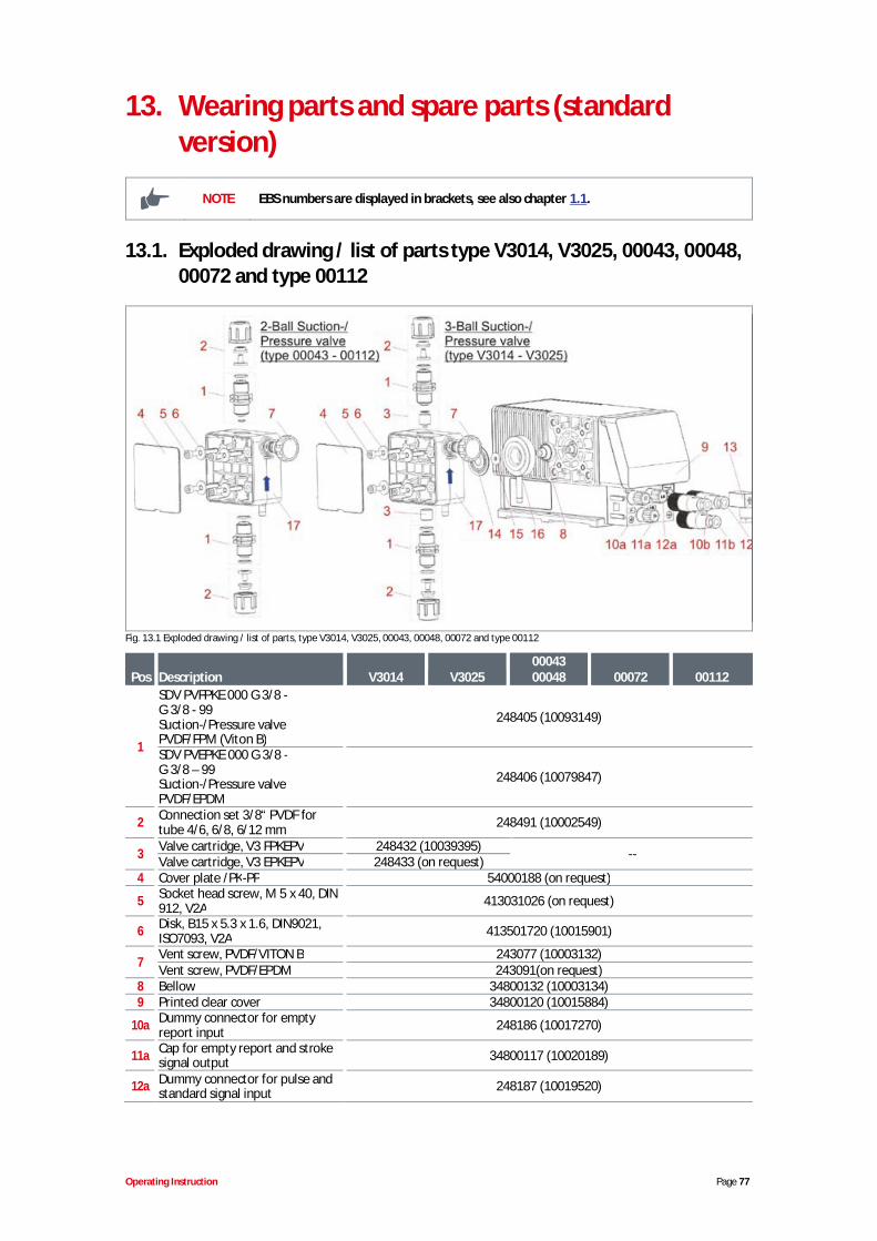
Operating Instruction Page 77
13. Wearing parts and spare parts (standardversion)
NOTE EBS numbers are displayed in brackets, see also chapter 1.1.
13.1. Exploded drawing / list of parts type V3014, V3025, 00043, 00048,00072 and type 00112
Fig. 13.1 Exploded drawing / list of parts, type V3014, V3025, 00043, 00048, 00072 and type 00112
Pos Description V3014 V30250004300048 00072 00112
1
SDV PVFPKE 000 G 3/8 -G 3/8 - 99Suction-/Pressure valvePVDF/FPM (Viton B)
248405 (10093149)
SDV PVEPKE 000 G 3/8 -G 3/8 – 99Suction-/Pressure valvePVDF/EPDM
248406 (10079847)
2 Connection set 3/8“ PVDF fortube 4/6, 6/8, 6/12 mm 248491 (10002549)
3 Valve cartridge, V3 FPKEPV 248432 (10039395) --Valve cartridge, V3 EPKEPV 248433 (on request)4 Cover plate /PK-PP 54000188 (on request)
5 Socket head screw, M 5 x 40, DIN912, V2A 413031026 (on request)
6 Disk, B15 x 5.3 x 1.6, DIN9021,ISO7093, V2A 413501720 (10015901)
7 Vent screw, PVDF/VITON B 243077 (10003132)Vent screw, PVDF/EPDM 243091(on request)
8 Bellow 34800132 (10003134)9 Printed clear cover 34800120 (10015884)
10a Dummy connector for emptyreport input 248186 (10017270)
11a Cap for empty report and strokesignal output 34800117 (10020189)
12a Dummy connector for pulse andstandard signal input 248187 (10019520)
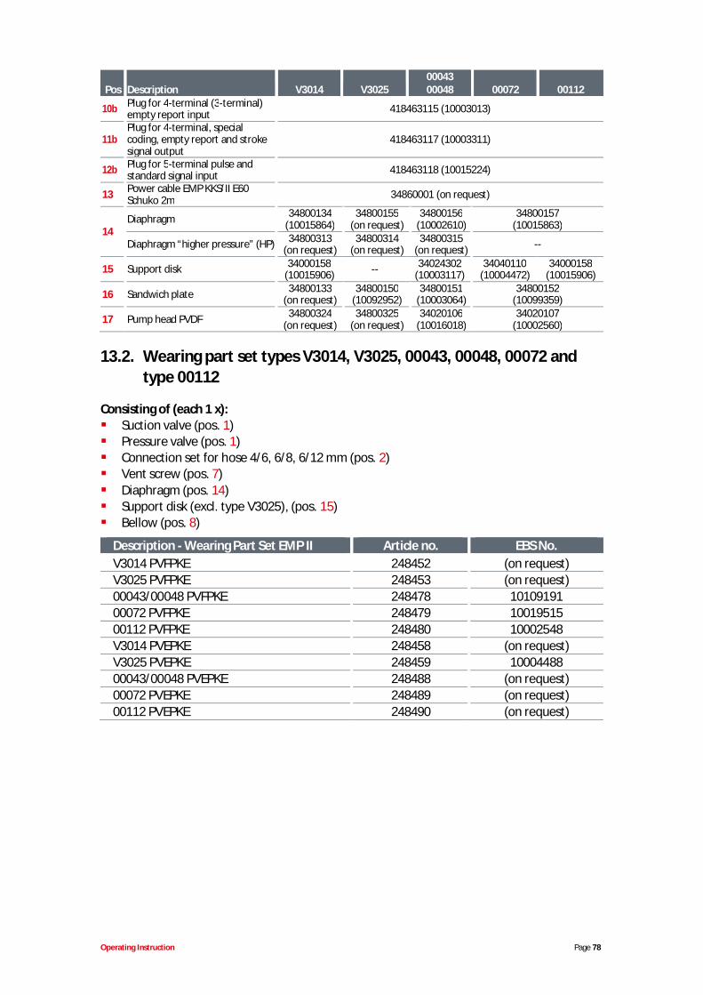
Operating Instruction Page 78
Pos Description V3014 V30250004300048 00072 00112
10b Plug for 4-terminal (3-terminal)empty report input 418463115 (10003013)
11bPlug for 4-terminal, specialcoding, empty report and strokesignal output
418463117 (10003311)
12b Plug for 5-terminal pulse andstandard signal input 418463118 (10015224)
13 Power cable EMP KKS/II E60Schuko 2m 34860001 (on request)
14Diaphragm 34800134
(10015864)34800155
(on request)34800156
(10002610)34800157
(10015863)
Diaphragm “higher pressure” (HP) 34800313(on request)
34800314(on request)
34800315(on request) --
15 Support disk 34000158(10015906) -- 34024302
(10003117)34040110
(10004472)34000158
(10015906)
16 Sandwich plate 34800133(on request)
34800150(10092952)
34800151(10003064)
34800152(10099359)
17 Pump head PVDF 34800324(on request)
34800325(on request)
34020106(10016018)
34020107(10002560)
13.2. Wearing part set types V3014, V3025, 00043, 00048, 00072 andtype 00112
Consisting of (each 1 x):Suction valve (pos. 1)Pressure valve (pos. 1)Connection set for hose 4/6, 6/8, 6/12 mm (pos. 2)Vent screw (pos. 7)Diaphragm (pos. 14)Support disk (excl. type V3025), (pos. 15)Bellow (pos. 8)
Description - Wearing Part Set EMP II Article no. EBS No.V3014 PVFPKE 248452 (on request)V3025 PVFPKE 248453 (on request)00043/00048 PVFPKE 248478 1010919100072 PVFPKE 248479 1001951500112 PVFPKE 248480 10002548V3014 PVEPKE 248458 (on request)V3025 PVEPKE 248459 1000448800043/00048 PVEPKE 248488 (on request)00072 PVEPKE 248489 (on request)00112 PVEPKE 248490 (on request)
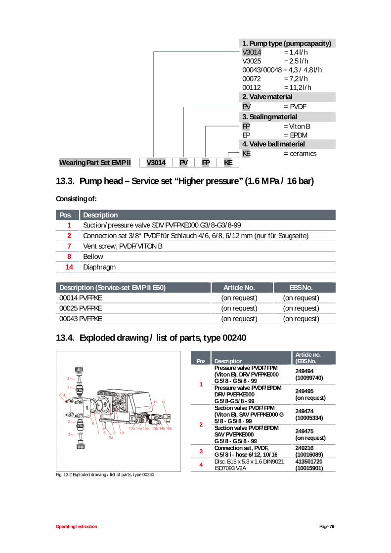
Operating Instruction Page 79
1. Pump type (pump capacity)V3014 = 1,4 l/hV3025 = 2,5 l/h00043/00048 = 4,3 / 4,8 l/h00072 = 7,2 l/h00112 = 11,2 l/h2. Valve materialPV = PVDF3. Sealing materialFP = Viton BEP = EPDM4. Valve ball materialKE = ceramics
Wearing Part Set EMP II V3014 PV FP KE
13.3. Pump head – Service set “Higher pressure” (1.6 MPa / 16 bar)
Consisting of:
Pos. Description1 Suction/pressure valve SDV PVFPKE000 G3/8-G3/8-992 Connection set 3/8“ PVDF für Schlauch 4/6, 6/8, 6/12 mm (nur für Saugseite)7 Vent screw, PVDF/VITON B8 Bellow
14 Diaphragm
Description (Service-set EMP II E60) Article No. EBS No.00014 PVFPKE (on request) (on request)00025 PVFPKE (on request) (on request)00043 PVFPKE (on request) (on request)
13.4. Exploded drawing / list of parts, type 00240
Pos DescriptionArticle no.(EBS No.
1
Pressure valve PVDF/FPM(Viton B), DRV PVFPKE000G 5/8 - G 5/8 - 99
249494(10099740)
Pressure valve PVDF/EPDMDRV PVEPKE000G 5/8-G 5/8 - 99
249495(on request)
2
Suction valve PVDF/FPM(Viton B), SAV PVFPKE000 G5/8 - G 5/8 - 99
249474(10005334)
Suction valve PVDF/EPDMSAV PVEPKE000G 5/8 - G 5/8 - 99
249475(on request)
3 Connection set, PVDF,G 5/8 i - hose 6/12, 10/16
249216(10016089)
4 Disc, B15 x 5.3 x 1.6 DIN9021ISO7093 V2A
413501720(10015901)
Fig. 13.2 Exploded drawing / list of parts, type 00240
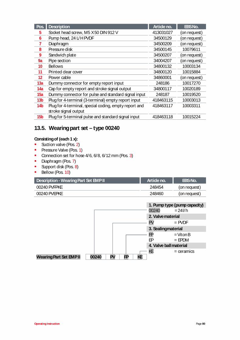
Operating Instruction Page 80
Pos. Description Article no. EBS No.5 Socket head screw, M5 X 50 DIN 912 V 413031027 (on request)6 Pump head, 24 L/H PVDF 34500129 (on request)7 Diaphragm 34500209 (on request)8 Pressure disk 34500145 100796119 Sandwich plate 34500207 (on request)
9a Pipe section 34004207 (on request)10 Bellows 34800132 1000313411 Printed clear cover 34800120 1001588412 Power cable 34860001 (on request)
13a Dummy connector for empty report input 248186 1001727014a Cap for empty report and stroke signal output 34800117 1002018915a Dummy connector for pulse and standard signal input 248187 1001952013b Plug for 4-terminal (3-terminal) empty report input 418463115 1000301314b Plug for 4-terminal, special coding, empty report and
stroke signal output418463117 10003311
15b Plug for 5-terminal pulse and standard signal input 418463118 10015224
13.5. Wearing part set – type 00240
Consisting of (each 1 x):Suction valve (Pos. 2)Pressure Valve (Pos. 1)Connection set for hose 4/6, 6/8, 6/12 mm (Pos. 3)Diaphragm (Pos. 7)Support disk (Pos. 8)Bellow (Pos. 10)
Description - Wearing Part Set EMP II Article no. EBS-No.00240 PVFPKE 248454 (on request)00240 PVEPKE 248460 (on request)
1. Pump type (pump capacity)00240 = 24 l/h2. Valve materialPV = PVDF3. Sealing materialFP = Viton BEP = EPDM4. Valve ball materialKE = ceramics
Wearing Part Set EMP II 00240 PV FP KE
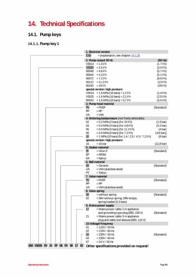
Operating Instruction Page 81
14. Technical Specifications14.1. Pump keys
Pump key 1
1. Electrical versionE 60 = (explanation, see chapter 14.1.3)2. Pump output 50 Hz (60 Hz)V3014 = 1.4 l/h (1.7 l/h)V3025 = 2.5 l/h (3.0 l/h)00048 = 4.8 l/h (5.7 l/h)00043 = 4.3 l/h (5.1 l/h)00072 = 7.2 l/h (8.6 l/h)00112 = 11.2 l/h (13 l/h)00240 = 24 l/h (29 l/h)spezial version: high pressure:V3014 = 1.6 MPa (16 bars) = 1,2 l/h (1,4 l/h)V3025 = 1.6 MPa (16 bars) = 2,1 l/h (2,5 l/h)00043 = 1.6 MPa (16 bars) = 3,7 l/h (4,4 l/h)3. Pump head materialPV = PVDF (Standard)PP = PPVA = V4A4. Metering backpressure (not freely selectable)02 = 0.2 MPa (2 bars) (for 24 l/h) (1.6 bar)04 = 0.4 MPa (4 bars) (for 4.8 l/h) (3.2 bar)05 = 0.5 MPa (5 bars) (for 11.2 l/h) (4 bar)06 = 0.6 MPa (6 bars) (for 7.2 l/h) (4,8 bar)]10 = 1 MPa (10 bars) (for 1.4 / 2.5 / 4.3 / 7.2 l/h) (8 bar)special version: high pressure:16 = 16 bar (12,8 bar)5. Gasket materialFP = Viton B (Standard)EP = EPDMKA = Kalrez6. Ball materialKE = Ceramic (Standard)VA = V4A (stainless steel)PT = Teflon7. Valve materialPV = PVDF (Standard)PP = PPVA = V4A (stainless steel)8. Valve spring99 = without spring (Standard)02 = SAV without spring; DRV simply
spring-loaded (0.3 bars)9. Mains power supply17 = Mains power cable 2 m appliance
and grounding type plug (E60, 230 V) (Standard)21 = Mains power cable 3 m appliance
plug and cable end sleeves (E60, 115 V)10.Voltage/frequency01 = 115V / 50 Hz02 = 115V / 60 Hz03 = 230V / 50 Hz (Standard)04 = 230V / 60 Hz07 = 24 V / 50 Hz
E60 V3025 PV 10 FP KE PV 99 17 03 Other specifications provided on request!
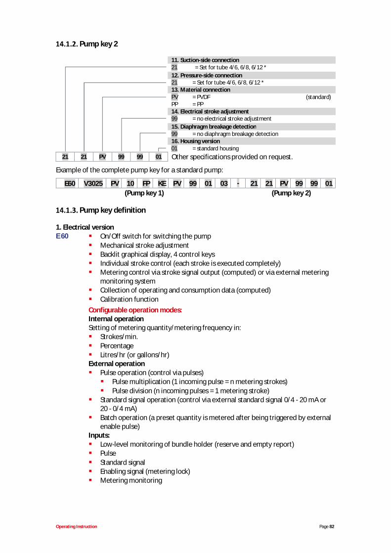
Operating Instruction Page 82
Pump key 2
11. Suction-side connection21 = Set for tube 4/6, 6/8, 6/12 *12. Pressure-side connection21 = Set for tube 4/6, 6/8, 6/12 *13. Material connectionPV = PVDF (standard)PP = PP14. Electrical stroke adjustment99 = no electrical stroke adjustment15. Diaphragm breakage detection99 = no diaphragm breakage detection16. Housing version01 = standard housing
21 21 PV 99 99 01 Other specifications provided on request.
Example of the complete pump key for a standard pump:
E60 V3025 PV 10 FP KE PV 99 01 03 - 21 21 PV 99 99 01(Pump key 1) (Pump key 2)
Pump key definition
1. Electrical versionE 60 On/Off switch for switching the pump
Mechanical stroke adjustmentBacklit graphical display, 4 control keysIndividual stroke control (each stroke is executed completely)Metering control via stroke signal output (computed) or via external meteringmonitoring systemCollection of operating and consumption data (computed)Calibration function
Configurable operation modes:Internal operationSetting of metering quantity/metering frequency in:
Strokes/min.PercentageLitres/hr (or gallons/hr)
External operationPulse operation (control via pulses)
Pulse multiplication (1 incoming pulse = n metering strokes)Pulse division (n incoming pulses = 1 metering stroke)
Standard signal operation (control via external standard signal 0/4 - 20 mA or20 - 0/4 mA)Batch operation (a preset quantity is metered after being triggered by externalenable pulse)
Inputs:Low-level monitoring of bundle holder (reserve and empty report)PulseStandard signalEnabling signal (metering lock)Metering monitoring

Operating Instruction Page 83
E 60 PLUS
Outputs:Low-level monitoring of bundle holder / fault (reserve and empty report)Fault reportStroke signalSimilar to E 60, but with the addition of a dongle box for connecting of ovalgear meter OGM PLUS (expansion unit for the capture of operating data)Display of the currently measured metering quantity and automaticreadjustment of pump output (only in conjunction with an external throughflow monitoring system, e.g. oval gear meter OGMPLUS)Automatic calibration function via oval gear meterConsumption data monitoring via oval gear meter
14.2. Dimensions
Type V3014, V3025, 00043, 00048, 00072 and type 00112
Fig. 14.1 type V3014, V3025, 00043, 00048, 00072 and type 00112
* linear dimension at type 00072 and 00112 with conventional synchronous motor as shown in figure 14.1 (246,6mm). linear dimension at type 00072 and 00112 with BLDC-Motor (visible at the voltage indication 100-240V atidentification plate) identical with types 00014 up to 00043 (218 mm).
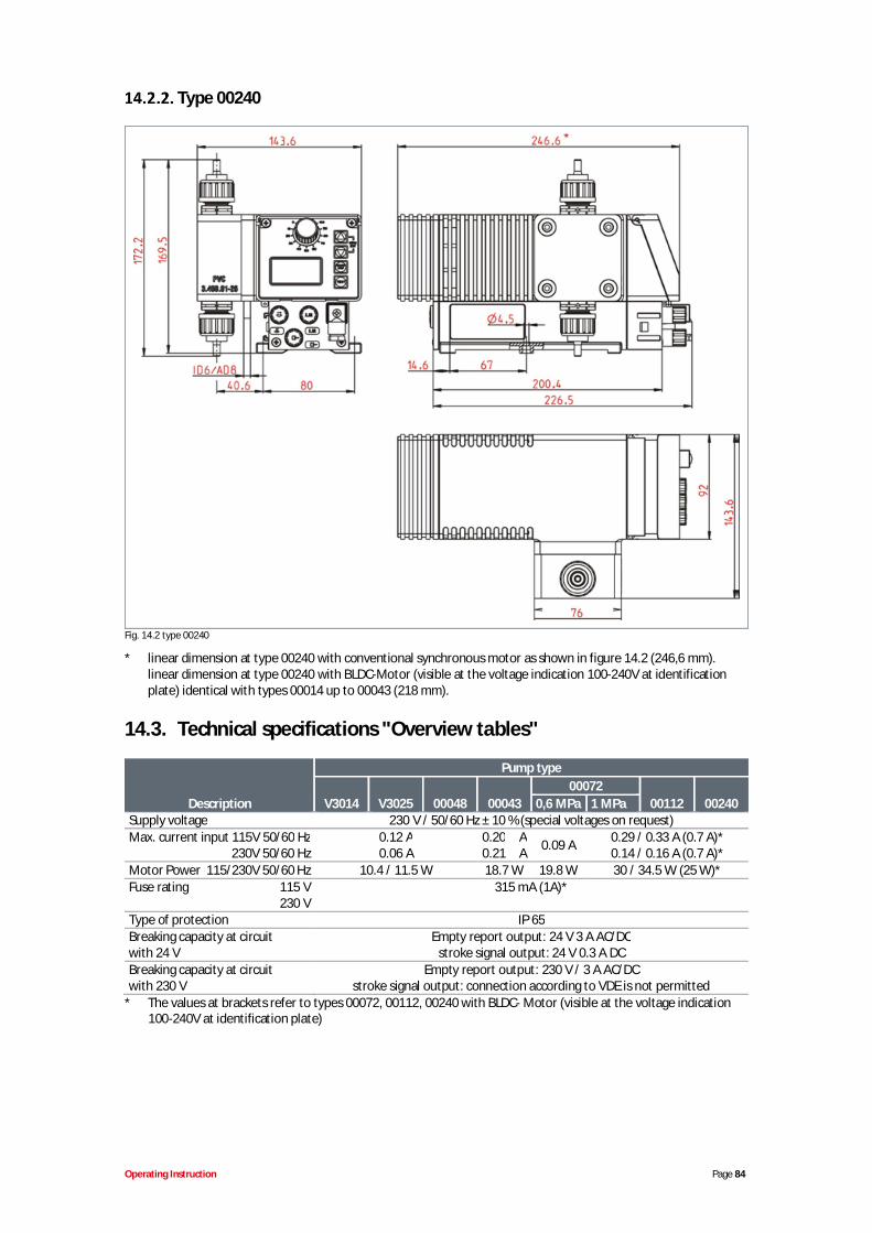
Operating Instruction Page 84
Type 00240
Fig. 14.2 type 00240
* linear dimension at type 00240 with conventional synchronous motor as shown in figure 14.2 (246,6 mm).linear dimension at type 00240 with BLDC-Motor (visible at the voltage indication 100-240V at identificationplate) identical with types 00014 up to 00043 (218 mm).
14.3. Technical specifications "Overview tables"
Description
Pump type
V3014 V3025 00048 0004300072
00112 002400,6 MPa 1 MPaSupply voltage 230 V / 50/60 Hz ± 10 % (special voltages on request)Max. current input 115V 50/60 Hz
230V 50/60 Hz0.12 A0.06 A
0.20 A0.21 A 0.09 A 0.29 / 0.33 A (0.7 A)*
0.14 / 0.16 A (0.7 A)*Motor Power 115/230V 50/60 Hz 10.4 / 11.5 W 18.7 W 19.8 W 30 / 34.5 W (25 W)*Fuse rating 115 V
230 V315 mA (1A)*
Type of protection IP 65Breaking capacity at circuitwith 24 V
Empty report output: 24 V 3 A AC/DCstroke signal output: 24 V 0.3 A DC
Breaking capacity at circuitwith 230 V
Empty report output: 230 V / 3 A AC/DCstroke signal output: connection according to VDE is not permitted
* The values at brackets refer to types 00072, 00112, 00240 with BLDC- Motor (visible at the voltage indication 100-240V at identification plate)
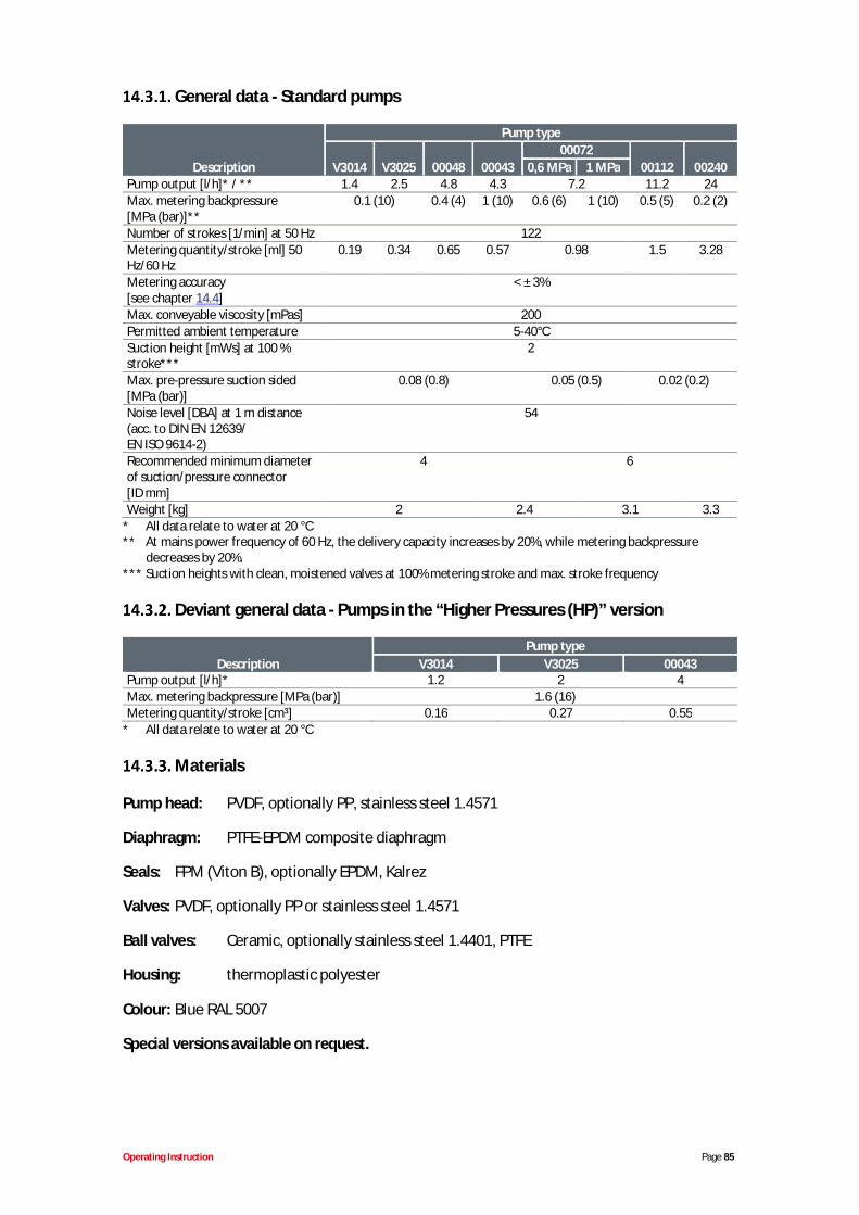
Operating Instruction Page 85
General data - Standard pumps
Description
Pump type
V3014 V3025 00048 0004300072
00112 002400,6 MPa 1 MPaPump output [l/h]* / ** 1.4 2.5 4.8 4.3 7.2 11.2 24Max. metering backpressure[MPa (bar)]**
0.1 (10) 0.4 (4) 1 (10) 0.6 (6) 1 (10) 0.5 (5) 0.2 (2)
Number of strokes [1/min] at 50 Hz 122Metering quantity/stroke [ml] 50Hz/60 Hz
0.19 0.34 0.65 0.57 0.98 1.5 3.28
Metering accuracy[see chapter 14.4]
< ± 3%
Max. conveyable viscosity [mPas] 200Permitted ambient temperature 5-40°CSuction height [mWs] at 100 %stroke***
2
Max. pre-pressure suction sided[MPa (bar)]
0.08 (0.8) 0.05 (0.5) 0.02 (0.2)
Noise level [DBA] at 1 m distance(acc. to DIN EN 12639/EN ISO 9614-2)
54
Recommended minimum diameterof suction/pressure connector[ID mm]
4 6
Weight [kg] 2 2.4 3.1 3.3* All data relate to water at 20 °C** At mains power frequency of 60 Hz, the delivery capacity increases by 20%, while metering backpressure
decreases by 20%.*** Suction heights with clean, moistened valves at 100% metering stroke and max. stroke frequency
Deviant general data - Pumps in the “Higher Pressures (HP)” version
DescriptionPump type
V3014 V3025 00043Pump output [l/h]* 1.2 2 4Max. metering backpressure [MPa (bar)] 1.6 (16)Metering quantity/stroke [cm³] 0.16 0.27 0.55
* All data relate to water at 20 °C
Materials
Pump head: PVDF, optionally PP, stainless steel 1.4571
Diaphragm: PTFE-EPDM composite diaphragm
Seals: FPM (Viton B), optionally EPDM, Kalrez
Valves: PVDF, optionally PP or stainless steel 1.4571
Ball valves: Ceramic, optionally stainless steel 1.4401, PTFE
Housing: thermoplastic polyester
Colour: Blue RAL 5007
Special versions available on request.
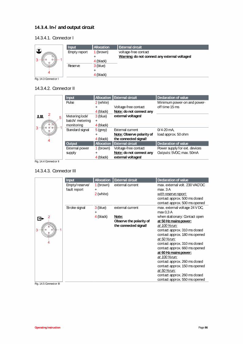
Operating Instruction Page 86
In-/ and output circuit
14.3.4.1. Connector I
Input Allocation External circuitEmpty report 1 (brown)
+4 (black)
voltage-free contactWarning: do not connect any external voltages!
Reserve 3 (blue)+4 (black)
Fig. 14.3 Connector I
14.3.4.2. Connector II
Input Allocation External circuit Declaration of valuePulse 2 (white)
+4 (black)
Voltage-free contactNote: do not connect anyexternal voltages!
Minimum power-on and power-off time 15 ms
Metering lock/batch/ meteringmonitoring
3 (blue)+4 (black)
Standard signal 5 (grey)+4 (black)
External currentNote: Observe polarity ofthe connected signal!
0/4-20 mA,load approx. 50 ohm
Output Allocation External circuit Declaration of valueExternal powersupply
1 (brown)+4 (black)
Voltage-free contactNote: do not connect anyexternal voltages!
Power supply for ext. devicesOutputs: 5VDC; max. 50mA
Fig. 14.4 Connector II
14.3.4.3. Connector III
Input Allocation External circuit Declaration of valueEmpty/reserve/fault report
1 (brown)+2 (white)
external current max. external volt. 230 VAC/DCmax. 3 Awith reserve report:contact approx. 500 ms closedcontact approx. 500 ms opened
Stroke signal 3 (blue)+4 (black)
external current
Note:Observe the polarity ofthe connected signal!
max. external voltage 24 V DC,max 0,3 Awhen stationary: Contact openat 50 Hz mains power:at 100 % run:contact approx. 310 ms closedcontact approx. 180 ms openedat 50 % run:contact approx. 310 ms closedcontact approx. 660 ms openedat 60 Hz mains power:at 100 % run:contact approx. 260 ms closedcontact approx. 150 ms openedat 50 % run:contact approx. 260 ms closedcontact approx. 550 ms opened
Fig. 14.5 Connector III
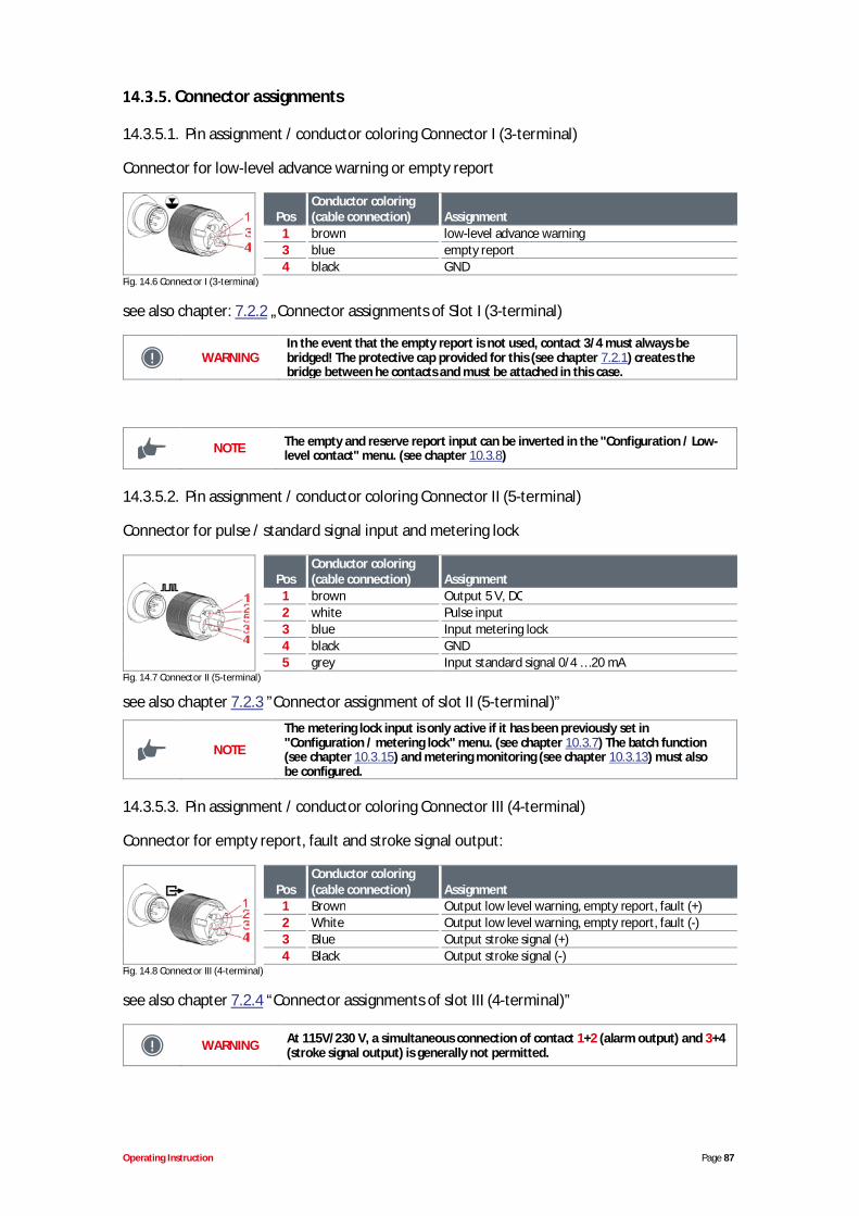
Operating Instruction Page 87
Connector assignments
14.3.5.1. Pin assignment / conductor coloring Connector I (3-terminal)
Connector for low-level advance warning or empty report
PosConductor coloring(cable connection) Assignment
1 brown low-level advance warning3 blue empty report4 black GND
Fig. 14.6 Connector I (3-terminal)
see also chapter: 7.2.2 „Connector assignments of Slot I (3-terminal)
WARNINGIn the event that the empty report is not used, contact 3/4 must always bebridged! The protective cap provided for this (see chapter 7.2.1) creates thebridge between he contacts and must be attached in this case.
NOTE The empty and reserve report input can be inverted in the "Configuration / Low-level contact" menu. (see chapter 10.3.8)
14.3.5.2. Pin assignment / conductor coloring Connector II (5-terminal)
Connector for pulse / standard signal input and metering lock
PosConductor coloring(cable connection) Assignment
1 brown Output 5 V, DC2 white Pulse input3 blue Input metering lock4 black GND5 grey Input standard signal 0/4 … 20 mA
Fig. 14.7 Connector II (5-terminal)
see also chapter 7.2.3 ”Connector assignment of slot II (5-terminal)”
NOTE
The metering lock input is only active if it has been previously set in"Configuration / metering lock" menu. (see chapter 10.3.7) The batch function(see chapter 10.3.15) and metering monitoring (see chapter 10.3.13) must alsobe configured.
14.3.5.3. Pin assignment / conductor coloring Connector III (4-terminal)
Connector for empty report, fault and stroke signal output:
PosConductor coloring(cable connection) Assignment
1 Brown Output low level warning, empty report, fault (+)2 White Output low level warning, empty report, fault (-)3 Blue Output stroke signal (+)4 Black Output stroke signal (-)
Fig. 14.8 Connector III (4-terminal)
see also chapter 7.2.4 “Connector assignments of slot III (4-terminal)”
WARNING At 115V/230 V, a simultaneous connection of contact 1+2 (alarm output) and 3+4(stroke signal output) is generally not permitted.
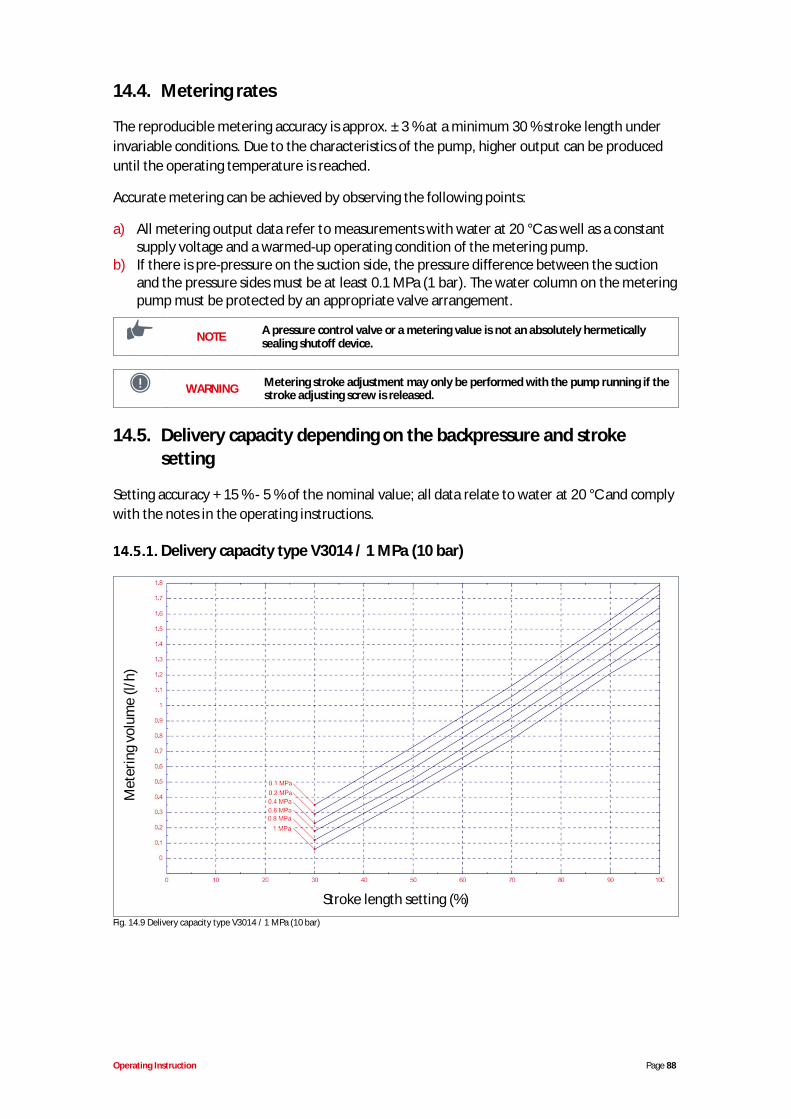
Operating Instruction Page 88
14.4. Metering rates
The reproducible metering accuracy is approx. ± 3 % at a minimum 30 % stroke length underinvariable conditions. Due to the characteristics of the pump, higher output can be produceduntil the operating temperature is reached.
Accurate metering can be achieved by observing the following points:
a) All metering output data refer to measurements with water at 20 °C as well as a constantsupply voltage and a warmed-up operating condition of the metering pump.
b) If there is pre-pressure on the suction side, the pressure difference between the suctionand the pressure sides must be at least 0.1 MPa (1 bar). The water column on the meteringpump must be protected by an appropriate valve arrangement.
NOTE A pressure control valve or a metering value is not an absolutely hermeticallysealing shutoff device.
WARNING Metering stroke adjustment may only be performed with the pump running if thestroke adjusting screw is released.
14.5. Delivery capacity depending on the backpressure and strokesetting
Setting accuracy + 15 % - 5 % of the nominal value; all data relate to water at 20 °C and complywith the notes in the operating instructions.
Delivery capacity type V3014 / 1 MPa (10 bar)
Met
erin
gvo
lum
e(l/
h)
Stroke length setting (%)Fig. 14.9 Delivery capacity type V3014 / 1 MPa (10 bar)
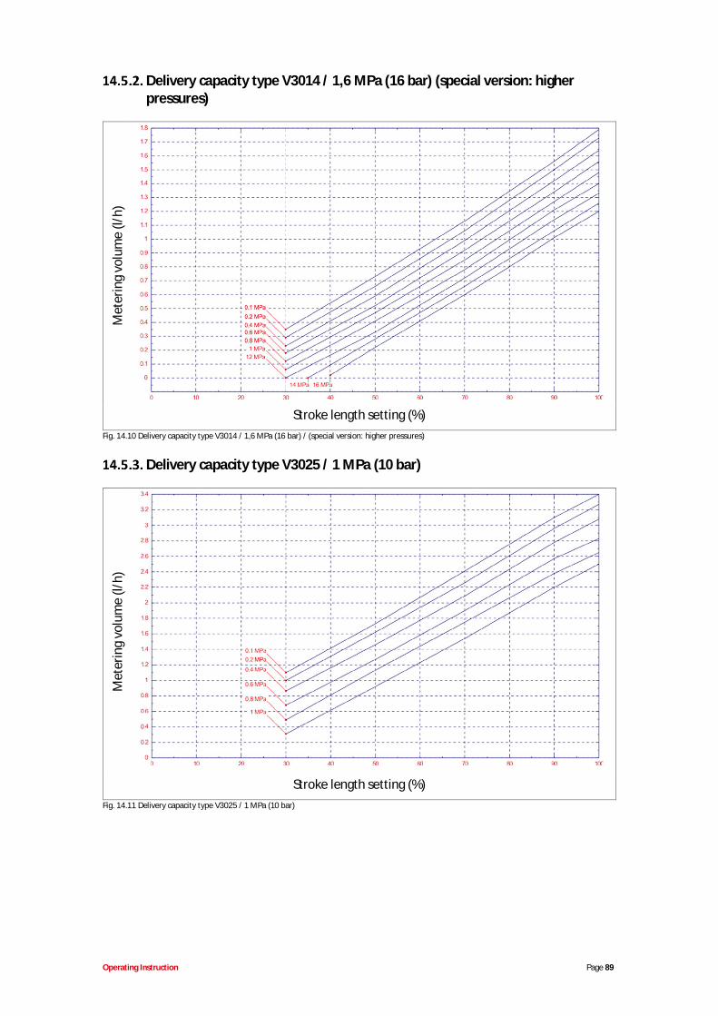
Operating Instruction Page 89
Delivery capacity type V3014 / 1,6 MPa (16 bar) (special version: higherpressures)
Met
erin
gvo
lum
e(l/
h)
Stroke length setting (%)Fig. 14.10 Delivery capacity type V3014 / 1,6 MPa (16 bar) / (special version: higher pressures)
Delivery capacity type V3025 / 1 MPa (10 bar)
Met
erin
gvo
lum
e(l/
h)
Stroke length setting (%)Fig. 14.11 Delivery capacity type V3025 / 1 MPa (10 bar)
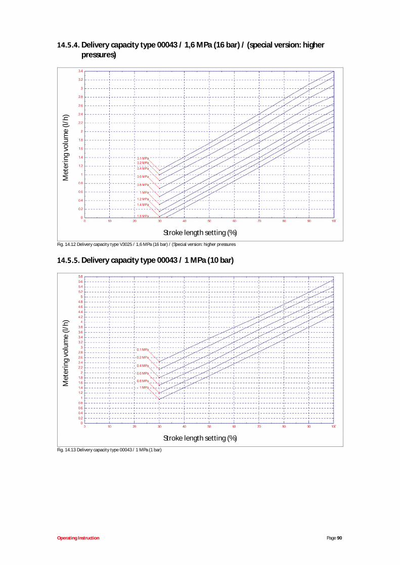
Operating Instruction Page 90
Delivery capacity type 00043 / 1,6 MPa (16 bar) / (special version: higherpressures)
Met
erin
gvo
lum
e(l/
h)
Stroke length setting (%)Fig. 14.12 Delivery capacity type V3025 / 1,6 MPa (16 bar) / (Special version: higher pressures
Delivery capacity type 00043 / 1 MPa (10 bar)
Met
erin
gvo
lum
e(l/
h)
Stroke length setting (%)Fig. 14.13 Delivery capacity type 00043 / 1 MPa (1 bar)

Operating Instruction Page 91
Delivery capacity type 00043 / 1,6 MPa (16 bar) / (special version: higherpressures)
Met
erin
gvo
lum
e(l/
h)
Stroke length setting (%)Fig. 14.14 Delivery capacity type 00043 / 1,6 MPa (16 bar) / (special version: higher pressures)
Delivery capacity type 00048 / 0,4 MPa (4 bar)
Met
erin
gvo
lum
e(l/
h)
Stroke length setting (%)Fig. 14.15 Delivery capacity type 00043 / 0,4 MPa (4 bar)
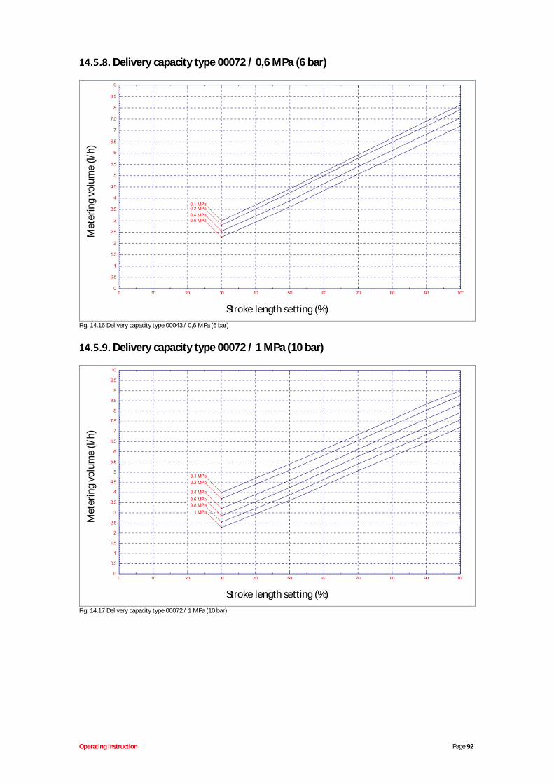
Operating Instruction Page 92
Delivery capacity type 00072 / 0,6 MPa (6 bar)
Met
erin
gvo
lum
e(l/
h)
Stroke length setting (%)Fig. 14.16 Delivery capacity type 00043 / 0,6 MPa (6 bar)
Delivery capacity type 00072 / 1 MPa (10 bar)
Met
erin
gvo
lum
e(l/
h)
Stroke length setting (%)Fig. 14.17 Delivery capacity type 00072 / 1 MPa (10 bar)
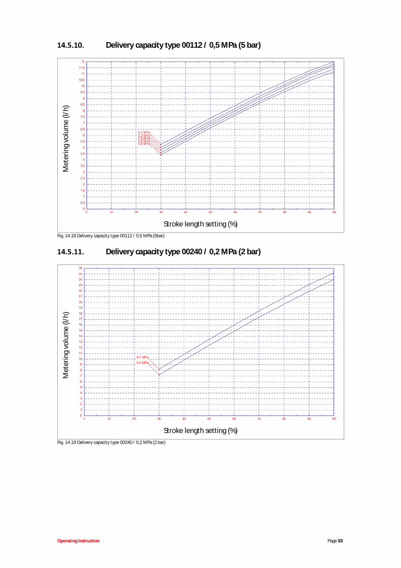
Operating Instruction Page 93
Delivery capacity type 00112 / 0,5 MPa (5 bar)
Met
erin
gvo
lum
e(l/
h)
Stroke length setting (%)Fig. 14.18 Delivery capacity type 00112 / 0,5 MPa (5bar)
Delivery capacity type 00240 / 0,2 MPa (2 bar)
Met
erin
gvo
lum
e(l/
h)
Stroke length setting (%)Fig. 14.19 Delivery capacity type 00240 / 0,2 MPa (2 bar)
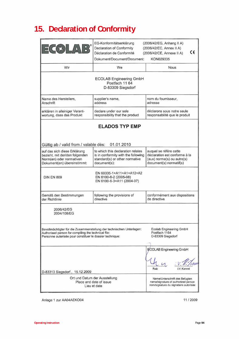
Operating Instruction Page 94
15. Declaration of Conformity
![WELCOME []...Emp B = $2350 Emp C = $500 Emp C = $3500 Emp D = $1500 Lag Quarter Emp D = $500 Claim filed Emp D = $150 The claimant must have been paid sufficient …](https://img.pdfslide.net/doc/110x75/607bc797dd97122c8938e959/welcome-emp-b-2350-emp-c-500-emp-c-3500-emp-d-1500-lag-quarter.jpg)