Embed Size (px)
Citation preview
Operating Instructions
HV 1.1-HV 1.2Incl. RS 485 - interface
English
210991-2HV1.1-2-ENV

Operating Instruction
www.hydrovar.com 2
Index
1 IMPORTANT SAFETY INSTRUCTIONS .......................................................................................... 4
2 SYSTEM DESIGN ........................................................................................................................ 6
3 PRESSURE TANK ....................................................................................................................... 7
4 TRANSDUCER............................................................................................................................. 8
4.1 PRESSURE TRANSMITTER SERIES PA-21 R ..........................................................................................84.2 DIFFERENTIAL PRESSURE TRANSMITTER SERIES PD 39 M.......................................................................9
5 TECHNICAL DATA - FREQUENCY INVERTER AND GENERAL DATA............................................. 10
5.1 DIMENSIONS ................................................................................................................................11
6 HYDROVAR MOUNTING........................................................................................................... 12
6.1 MOUNTING THE HYDROVAR ON THE PUMP .......................................................................................126.1.1 Included components...........................................................................................................126.1.2 Mechanical mounting ..........................................................................................................136.1.3 Mounting the thermistor .....................................................................................................166.1.4 Mounting of the pressure transducer..................................................................................17
6.2 ELECTRIC INSTALLATION AND WIRING..................................................................................................186.2.1 Means of protection.............................................................................................................186.2.2 Wiring the Hydrovar to the motor........................................................................................186.2.3 Control.................................................................................................................................216.2.4 Terminals .............................................................................................................................21
6.3 FRONT PLATE ................................................................................................................................23
7 OPERATION WITHOUT EXTERNAL PROGRAMMING DEVICE...................................................... 24
8 POSSIBLE INDICATIONS OF THE LED ON THE HYDROVAR......................................................... 25
9 OPERATION IN THE MAIN MENU ............................................................................................. 26
10 CONNECTING THE EXTERNAL PROGRAMMING DEVICE TO THE HYDROVAR............................. 27
11 TYPICAL APPLICATIONS ........................................................................................................... 28
11.1 SETTING SINGLE PUMP CONSTANT PRESSURE .......................................................................................2811.2 SINGLE PUMP - PUMP PROTECTION....................................................................................................2911.3 SINGLE PUMP – SYSTEM CURVE COMPENSATION ..................................................................................3111.4 ENTERING COMPENSATION VALUES ...................................................................................................32MULTIPLE PUMP CONSTANT PRESSURE AND SYSTEM COMPENSATION....................................................................34
12 SETTINGS AT THE INVERTERMENU........................................................................................... 39
13 SETTINGS AT THE SUBMENU-PARAMETER ............................................................................... 40
13.1 PRESSURE CHANGE.........................................................................................................................4013.2 AUTO START .................................................................................................................................4013.3 MODE.........................................................................................................................................4013.4 CONTROL RESPONSE.......................................................................................................................41
13.4.1 Dimension unit ...................................................................................................................4113.5 SUBMENU INVERTER .......................................................................................................................41
13.5.1 Maximum Frequency...........................................................................................................4113.5.2 Minimum frequency............................................................................................................4213.5.3 Boost ..................................................................................................................................4213.5.4 Operation of the minimum frequency.................................................................................4213.5.5 Delay time for Fmin.............................................................................................................42
13.6 SUBMENU CONTROLLER ..................................................................................................................42
Operating Instruction
www.hydrovar.com 3
13.6.1 Window - %........................................................................................................................4313.6.2 Ramp Hysteresis..................................................................................................................4313.6.3 Fast acceleration time .........................................................................................................4313.6.4 Fast deceleration time.........................................................................................................4313.6.5 Slow acceleration time........................................................................................................4313.6.6 Slow deceleration time .......................................................................................................44
RAMP WINDOW......................................................................................................................................4413.6.7 Compensation Frequency....................................................................................................4413.6.8 Lift-Intensity........................................................................................................................44
13.7 SUBMENU MULTICONTROLLER ..........................................................................................................4513.7.1 Lift Value ............................................................................................................................4513.7.2 Fall Value ............................................................................................................................4513.7.3 Release – Follow up pump ..................................................................................................4613.7.4 Switch Interval ....................................................................................................................46
13.8 SUBMENU RELAY ...........................................................................................................................4713.8.1 Relay Configuration ............................................................................................................4713.8.2 Start frequency of the slave pump......................................................................................4713.8.3 Stop frequency of the slave pump ......................................................................................47
13.9 SUBMENU SENSOR.........................................................................................................................4713.9.1 Sensor – Adjust ...................................................................................................................4813.9.2 SensorMax-Adjust ...............................................................................................................48
13.10 SUBMENU TEST-RUN ......................................................................................................................4813.10.1 Start of manual test run....................................................................................................4813.10.2 Sequence for automatic test run.......................................................................................4813.10.3 Test Run: Frequency .........................................................................................................4813.10.4 Test Run: Boost.................................................................................................................49
13.11 SUBMENU ERROR...........................................................................................................................4913.11.1 Conveyor Limit..................................................................................................................4913.11.2 Error Delay ........................................................................................................................49
13.12 SET PASSWORD.............................................................................................................................4913.13 DEFAULT SETTINGS.........................................................................................................................4913.14 SUBMENU DIAGNOSIS.....................................................................................................................49
13.14.1 Pump Runtime ..................................................................................................................5013.14.2 Pump Address...................................................................................................................5013.14.3 Error memory....................................................................................................................5013.14.4 Software Version ..............................................................................................................50
13.15 SET PASSWORD.............................................................................................................................50
14 CONTROLLER MENU (OF THE PROGRAMMING DEVICE)........................................................... 50
14.1 CONTROLLER MENU CONFIGURATION .................................................................................................5114.1.1 Automatic connection to the programming device .............................................................5114.1.2 Software Version of the programming device.....................................................................51
14.2 SUBMENU ADDRESS........................................................................................................................5114.2.1 Change of pump address....................................................................................................51
15 POSSIBLE ERROR MESSAGES ................................................................................................... 52
15.1 LOW WATER.................................................................................................................................5215.2 OVERHEATING – MOTOR.................................................................................................................5215.3 OVERVOLTAGE ..............................................................................................................................5215.4 UNDERVOLTAGE ............................................................................................................................5215.5 OVERLOAD...................................................................................................................................5215.6 OVERHEATING OF THE HEAT SINK.......................................................................................................5215.7 SENSOR FAULT ..............................................................................................................................5315.8 CONVEYOR LIMIT FAULT...................................................................................................................5315.9 ADDITIONAL INTERNAL PROCESSOR ERROR MESSAGES: ...........................................................................53
16 MAINTENANCE ........................................................................................................................ 53
Follow the Pump Operating and Maintenance InstructionsWe reserv the right to alter specifications
Operating Instruction
www.hydrovar.com 4
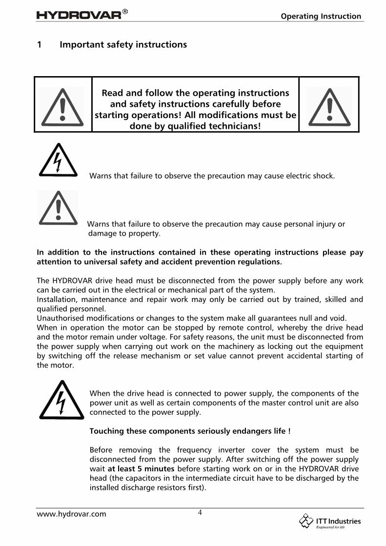
1 Important safety instructions
Read and follow the operating instructionsand safety instructions carefully before
starting operations! All modifications must bedone by qualified technicians!
Warns that failure to observe the precaution may cause electric shock.
Warns that failure to observe the precaution may cause personal injury or damage to property.
In addition to the instructions contained in these operating instructions please payattention to universal safety and accident prevention regulations.
The HYDROVAR drive head must be disconnected from the power supply before any workcan be carried out in the electrical or mechanical part of the system.Installation, maintenance and repair work may only be carried out by trained, skilled andqualified personnel.Unauthorised modifications or changes to the system make all guarantees null and void.When in operation the motor can be stopped by remote control, whereby the drive headand the motor remain under voltage. For safety reasons, the unit must be disconnected fromthe power supply when carrying out work on the machinery as locking out the equipmentby switching off the release mechanism or set value cannot prevent accidental starting ofthe motor.
When the drive head is connected to power supply, the components of thepower unit as well as certain components of the master control unit are alsoconnected to the power supply.
Touching these components seriously endangers life !
Before removing the frequency inverter cover the system must bedisconnected from the power supply. After switching off the power supplywait at least 5 minutes before starting work on or in the HYDROVAR drivehead (the capacitors in the intermediate circuit have to be discharged by theinstalled discharge resistors first).

Operating Instruction
www.hydrovar.com 5
Voltages of up to 400 volts are possible (if there are faults it can be higher).
All work carried out when the frequency inverter is open may only beperformed by qualified authorised staff.
Furthermore, care must be taken not to short circuit the neighbouringcomponents when connecting the external control wires and that opencable ends which are not in use are insulated.
The HYDROVAR drive head contains electronic safety devices which switch offthe control element in the event of faults, whereby the motor has zero currentbut remains energised and comes to a halt. The motor can also be halted bymechanical blocking. If it is switched off electronically the motor isdisconnected from the mains voltage through the electronics of the frequencyconverter but is not potential-free in the circuit.In addition voltage fluctuations, especially power failures can cause thesystem to switch off itself.Repair of faults can cause the motor to start up again.
The system may only be put into operation when it has been earthened. In addition,equipotential bonding of all pipes must be ensured.
The operating instructions must be read, understood and followed by the operatingpersonnel. We point out that we accept no liability for damage and operating disorderswhich are the result of non-compliance with the operating instructions.
Pleasenote:
High voltage tests of the inverter or the motor may damage theelectronic components! Hence bridge before the in- and outgoingterminals L -N -- U- V-W.To avoid incorrect metering by capacitors incorporated in theelectronic part isolate the motor from the Hydrovar Drive head.
Operating Instruction
www.hydrovar.com 6
2 System Design
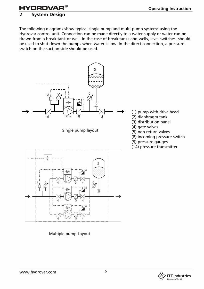
The following diagrams show typical single pump and multi-pump systems using theHydrovar control unit. Connection can be made directly to a water supply or water can bedrawn from a break tank or well. In the case of break tanks and wells, level switches, shouldbe used to shut down the pumps when water is low. In the direct connection, a pressureswitch on the suction side should be used.
Single pump layout
Multiple pump Layout
(1) pump with drive head(2) diaphragm tank(3) distribution panel(4) gate valves(5) non return valves(8) incoming pressure switch(9) pressure gauges(14) pressure transmitter
Operating Instruction
www.hydrovar.com 7
3 Pressure tank
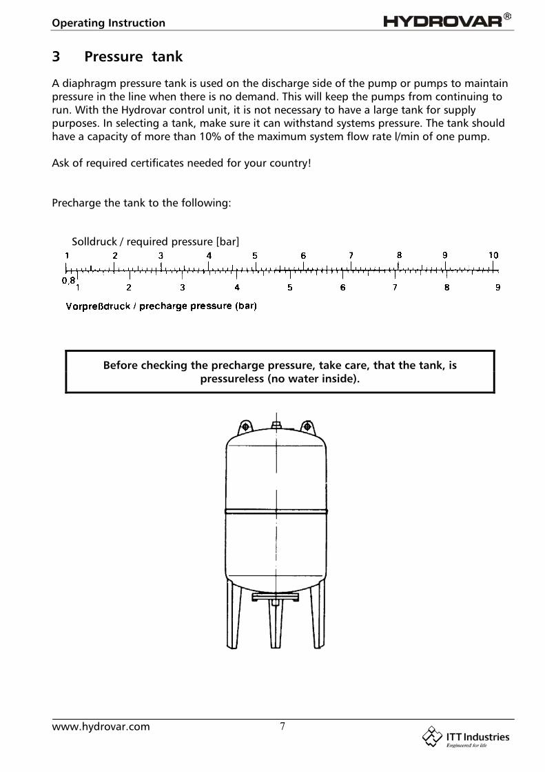
A diaphragm pressure tank is used on the discharge side of the pump or pumps to maintainpressure in the line when there is no demand. This will keep the pumps from continuing torun. With the Hydrovar control unit, it is not necessary to have a large tank for supplypurposes. In selecting a tank, make sure it can withstand systems pressure. The tank shouldhave a capacity of more than 10% of the maximum system flow rate l/min of one pump.
Ask of required certificates needed for your country!
Precharge the tank to the following:
Before checking the precharge pressure, take care, that the tank, ispressureless (no water inside).
Solldruck / required pressure [bar]
Operating Instruction
www.hydrovar.com 8
4 Transducer
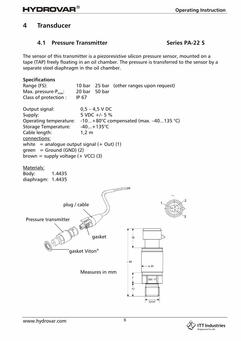
4.1 Pressure Transmitter Series PA-22 S
The sensor of this transmitter is a piezoresistive silicon pressure sensor, mounted on atape (TAP) freely floating in an oil chamber. The pressure is transferred to the sensor by aseparate steel diaphragm in the oil chamber.
SpecificationsRange (FS): 10 bar 25 bar (other ranges upon request)Max. pressure-Pmax: 20 bar 50 barClass of protection : IP 67
Output signal: 0,5 – 4,5 V DCSupply: 5 VDC +/- 5 %Operating temperature: -10...+80°C compensated (max. –40...135 °C)Storage Temperature: -40...+135°CCable length: 1,2 mconnections:white = analogue output signal (+ Out) (1)green = Ground (GND) (2)brown = supply voltage (+ VCC) (3)
Materials:Body: 1.4435diaphragm: 1.4435
Measures in mm
gasket Viton®
Pressure transmitter
gasket
plug / cable
Operating Instruction
www.hydrovar.com 9
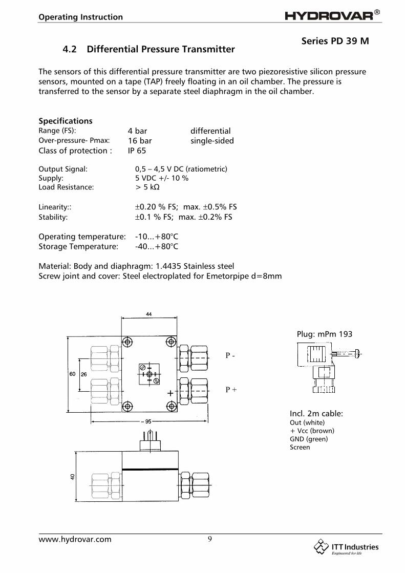
4.2 Differential Pressure TransmitterSeries PD 39 M
The sensors of this differential pressure transmitter are two piezoresistive silicon pressuresensors, mounted on a tape (TAP) freely floating in an oil chamber. The pressure istransferred to the sensor by a separate steel diaphragm in the oil chamber.
SpecificationsRange (FS): 4 bar differentialOver-pressure- Pmax: 16 bar single-sidedClass of protection : IP 65
Output Signal: 0,5 – 4,5 V DC (ratiometric)Supply: 5 VDC +/- 10 %Load Resistance: > 5 kΩ
Linearity:: 0.20 % FS; max. 0.5% FSStability: 0.1 % FS; max. 0.2% FS
Operating temperature: -10...+80°CStorage Temperature: -40...+80°C
Material: Body and diaphragm: 1.4435 Stainless steelScrew joint and cover: Steel electroplated for Emetorpipe d=8mm
Plug: mPm 193
Incl. 2m cable:Out (white)+ Vcc (brown)GND (green)Screen
P -
P +
Operating Instruction
www.hydrovar.com 10
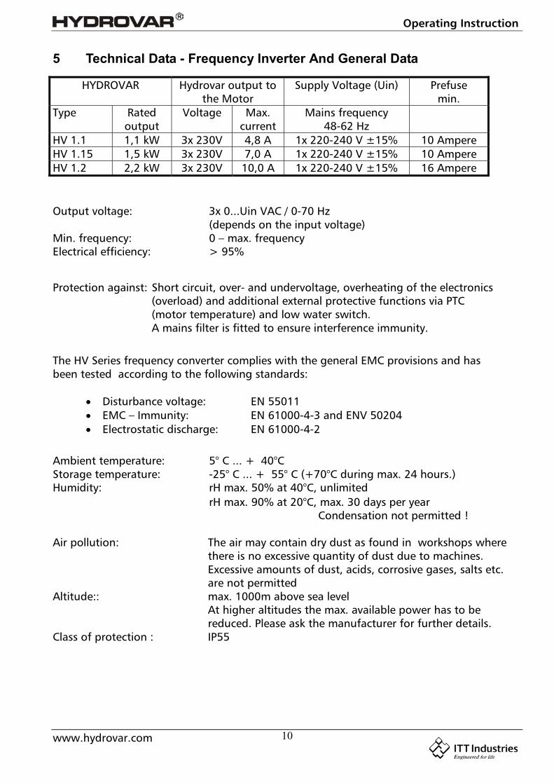
5 Technical Data - Frequency Inverter And General Data
HYDROVAR Hydrovar output tothe Motor
Supply Voltage (Uin) Prefusemin.
Type Ratedoutput
Voltage Max.current
Mains frequency48-62 Hz
HV 1.1 1,1 kW 3x 230V 4,8 A 1x 220-240 V ±15% 10 AmpereHV 1.15 1,5 kW 3x 230V 7,0 A 1x 220-240 V ±15% 10 AmpereHV 1.2 2,2 kW 3x 230V 10,0 A 1x 220-240 V ±15% 16 Ampere
Output voltage: 3x 0...Uin VAC / 0-70 Hz(depends on the input voltage)
Min. frequency: 0 – max. frequencyElectrical efficiency: > 95%
Protection against: Short circuit, over- and undervoltage, overheating of the electronics(overload) and additional external protective functions via PTC(motor temperature) and low water switch.A mains filter is fitted to ensure interference immunity.
The HV Series frequency converter complies with the general EMC provisions and hasbeen tested according to the following standards:
Disturbance voltage: EN 55011 EMC – Immunity: EN 61000-4-3 and ENV 50204 Electrostatic discharge: EN 61000-4-2
Ambient temperature: 5° C ... + 40°CStorage temperature: -25° C ... + 55° C (+70°C during max. 24 hours.)Humidity: rH max. 50% at 40°C, unlimited
rH max. 90% at 20°C, max. 30 days per year Condensation not permitted !
Air pollution: The air may contain dry dust as found in workshops wherethere is no excessive quantity of dust due to machines.Excessive amounts of dust, acids, corrosive gases, salts etc.are not permitted
Altitude:: max. 1000m above sea levelAt higher altitudes the max. available power has to bereduced. Please ask the manufacturer for further details.
Class of protection : IP55
Operating Instruction
www.hydrovar.com 11
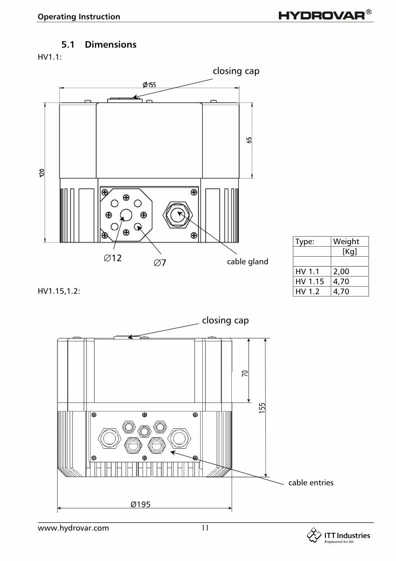
5.1 DimensionsHV1.1:
HV1.15,1.2:
closing cap
712
Type: Weight[Kg]
HV 1.1 2,00HV 1.15 4,70HV 1.2 4,70
closing cap
cable entries
cable gland
Operating Instruction
www.hydrovar.com 12
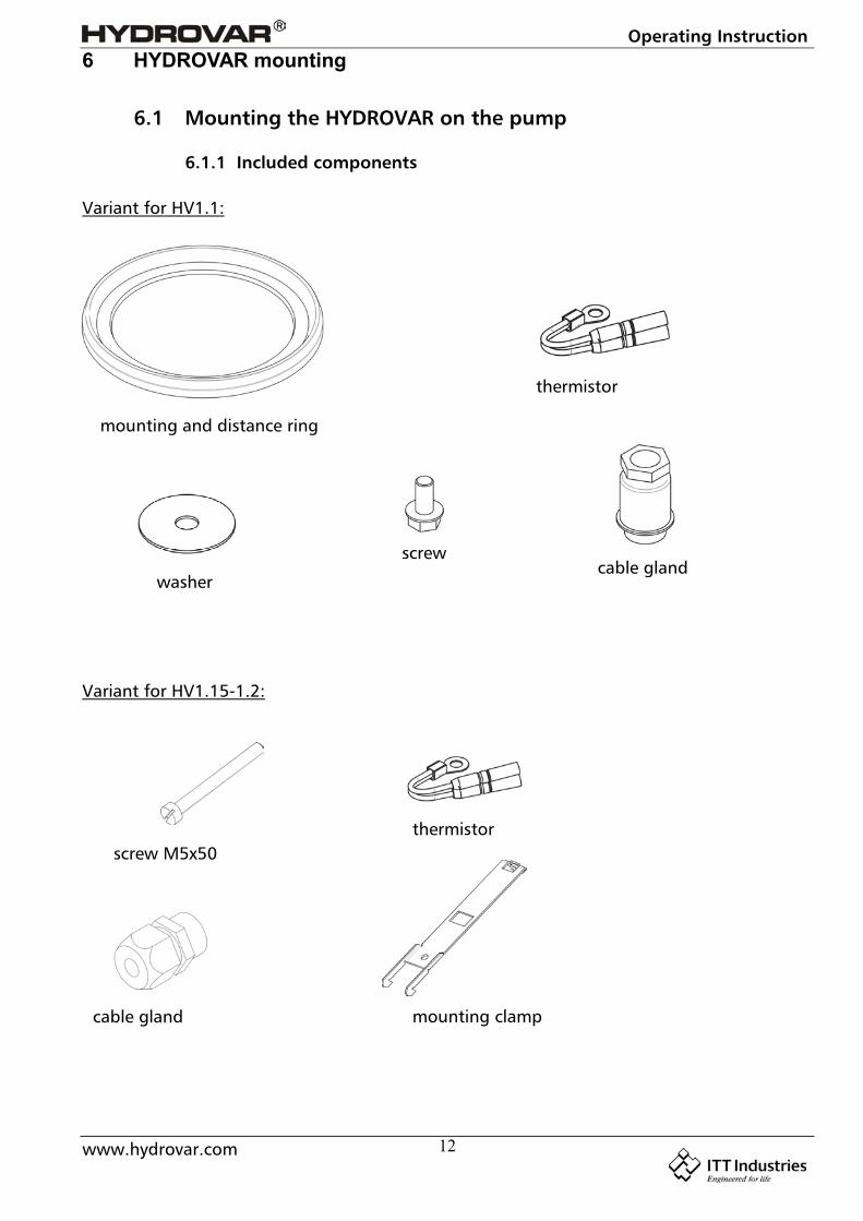
6 HYDROVAR mounting
6.1 Mounting the HYDROVAR on the pump
6.1.1 Included components
Variant for HV1.1:
Variant for HV1.15-1.2:
mounting and distance ring
washer
screwcable gland
thermistor
thermistor
cable gland
screw M5x50
mounting clamp
Operating Instruction
www.hydrovar.com 13
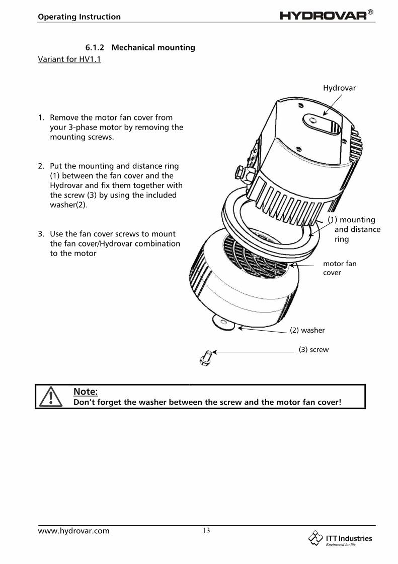
6.1.2 Mechanical mountingVariant for HV1.1
1. Remove the motor fan cover fromyour 3-phase motor by removing themounting screws.
2. Put the mounting and distance ring(1) between the fan cover and theHydrovar and fix them together withthe screw (3) by using the includedwasher(2).
3. Use the fan cover screws to mountthe fan cover/Hydrovar combinationto the motor
Note:Don’t forget the washer between the screw and the motor fan cover!
Hydrovar
(1) mounting and distance ring
motor fancover
(2) washer
(3) screw
Operating Instruction
www.hydrovar.com 14
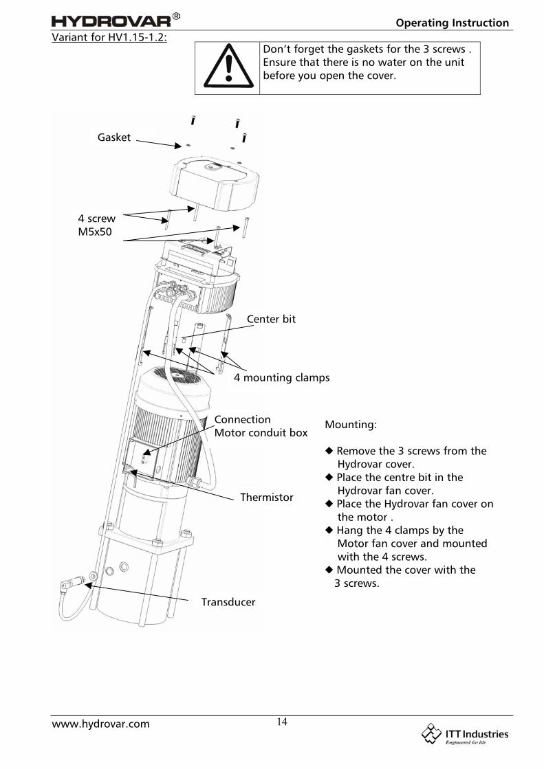
Variant for HV1.15-1.2:
Gasket
Thermistor
Transducer
ConnectionMotor conduit box
4 mounting clamps
Center bit
4 screwM5x50
Mounting:
Remove the 3 screws from the Hydrovar cover. Place the centre bit in the Hydrovar fan cover. Place the Hydrovar fan cover on the motor . Hang the 4 clamps by the Motor fan cover and mounted with the 4 screws. Mounted the cover with the 3 screws.
Don’t forget the gaskets for the 3 screws .Ensure that there is no water on the unitbefore you open the cover.
Operating Instruction
www.hydrovar.com 15
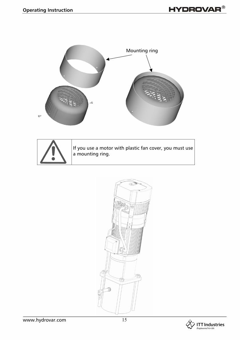
If you use a motor with plastic fan cover, you must usea mounting ring.
Mounting ring
Operating Instruction
www.hydrovar.com 16
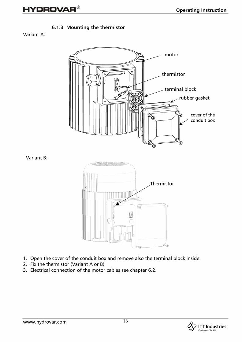
6.1.3 Mounting the thermistorVariant A:
Variant B:
1. Open the cover of the conduit box and remove also the terminal block inside.2. Fix the thermistor (Variant A or B)3. Electrical connection of the motor cables see chapter 6.2.
motor
thermistor
terminal block
rubber gasket
cover of theconduit box
Thermistor

Operating Instruction
www.hydrovar.com 17
6.1.4 Mounting of the pressure transducer
In the delivery of the pressure transducer there are included:
1. The transducer has an mechanical connection of G ¼”.
2. Electrical connection to the Hydrovar see chapter (6.2)
gasket Viton®
Pressure transmitter
gasket
plug / cable
Operating Instruction
www.hydrovar.com 18
6.2 Electric installation and wiring
6.2.1 Means of protection
Ask your power supply company which means of protection are required.
Applicable: AC and DC current-operated circuit breaker (FI), TN systems, protectivecircuits.
When using a FI protection switch, make sure that it also releases in the event ofa DC fault, use for each Hydrovar a separate FI-switch!
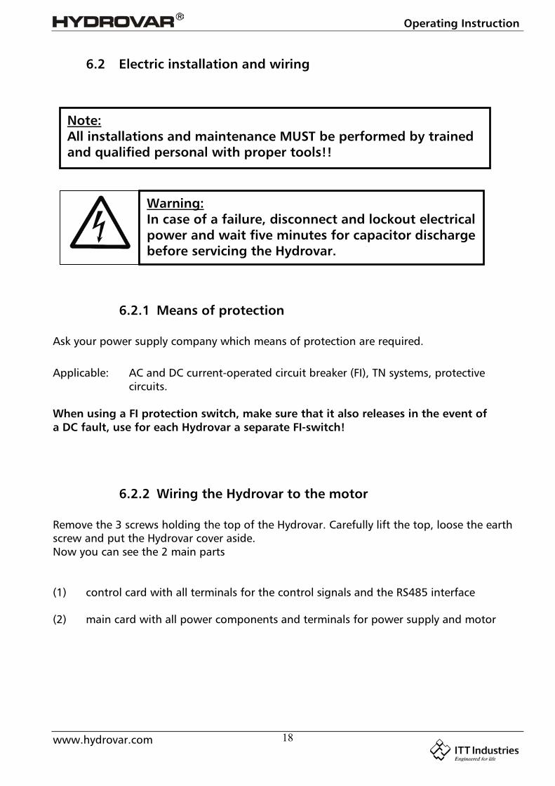
6.2.2 Wiring the Hydrovar to the motor
Remove the 3 screws holding the top of the Hydrovar. Carefully lift the top, loose the earthscrew and put the Hydrovar cover aside.Now you can see the 2 main parts
(1) control card with all terminals for the control signals and the RS485 interface
(2) main card with all power components and terminals for power supply and motor
Note:All installations and maintenance MUST be performed by trainedand qualified personal with proper tools!!
Warning:In case of a failure, disconnect and lockout electricalpower and wait five minutes for capacitor dischargebefore servicing the Hydrovar.
Operating Instruction
www.hydrovar.com 19
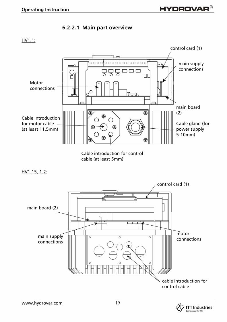
6.2.2.1 Main part overview
HV1.1:
HV1.15, 1.2:
Motorconnections
main supplyconnections
Cable gland (forpower supply5-10mm)
control card (1)
main board(2)
Cable introductionfor motor cable(at least 11,5mm)
Cable introduction for controlcable (at least 5mm)
motorconnections
main supplyconnections
control card (1)
main board (2)
cable introduction forcontrol cable

Operating Instruction
www.hydrovar.com 20
6.2.2.2 Connecting the power cables
a) motor cable:
Locate the motor connections, labeled U, V, W inside the Hydrovar. Connect wires to theterminals and rout the cable through the cable gland.You must take a motor cable at least Ø 11.5mm if you want protection IP55. (only HV1.1)
The earth-wire of the cable has to be fixed with the screws with the earth-symbol to thecooling body of the Hydrovar.
Connections in the conduit box
The connection of the motor cable depends on the type of the motor and can be done instar or delta connection:(you have to use the connection for a motor voltage of 3x230V shown on the motor label)
Star-connection Delta-connection
b) supply cable
The main power cable is connected to the terminals labelled L1, N for the 230 VAC, singlephase input (shown in the diagram 6.2.2.1).
Operating Instruction
www.hydrovar.com 21
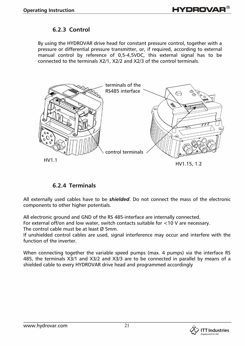
6.2.3 Control
By using the HYDROVAR drive head for constant pressure control, together with apressure or differential pressure transmitter, or, if required, according to externalmanual control by reference of 0,5-4,5VDC, this external signal has to beconnected to the terminals X2/1, X2/2 and X2/3 of the control terminals.
6.2.4 Terminals
All externally used cables have to be shielded. Do not connect the mass of the electroniccomponents to other higher potentials.
All electronic ground and GND of the RS 485-interface are internally connected.For external off/on and low water, switch contacts suitable for <10 V are necessary.The control cable must be at least Ø 5mm.If unshielded control cables are used, signal interference may occur and interfere with thefunction of the inverter.
When connecting together the variable speed pumps (max. 4 pumps) via the interface RS485, the terminals X3/1 and X3/2 and X3/3 are to be connected in parallel by means of ashielded cable to every HYDROVAR drive head and programmed accordingly
control terminals
terminals of theRS485 interface
HV1.1HV1.15, 1.2
Operating Instruction
www.hydrovar.com 22
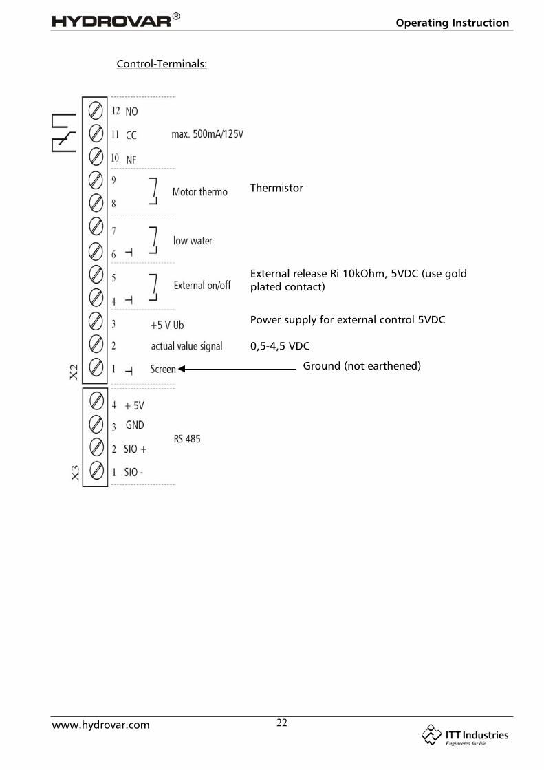
Control-Terminals:
Power supply for external control 5VDC
External release Ri 10kOhm, 5VDC (use goldplated contact)
Thermistor
Ground (not earthened)
0,5-4,5 VDC
Operating Instruction
www.hydrovar.com 23
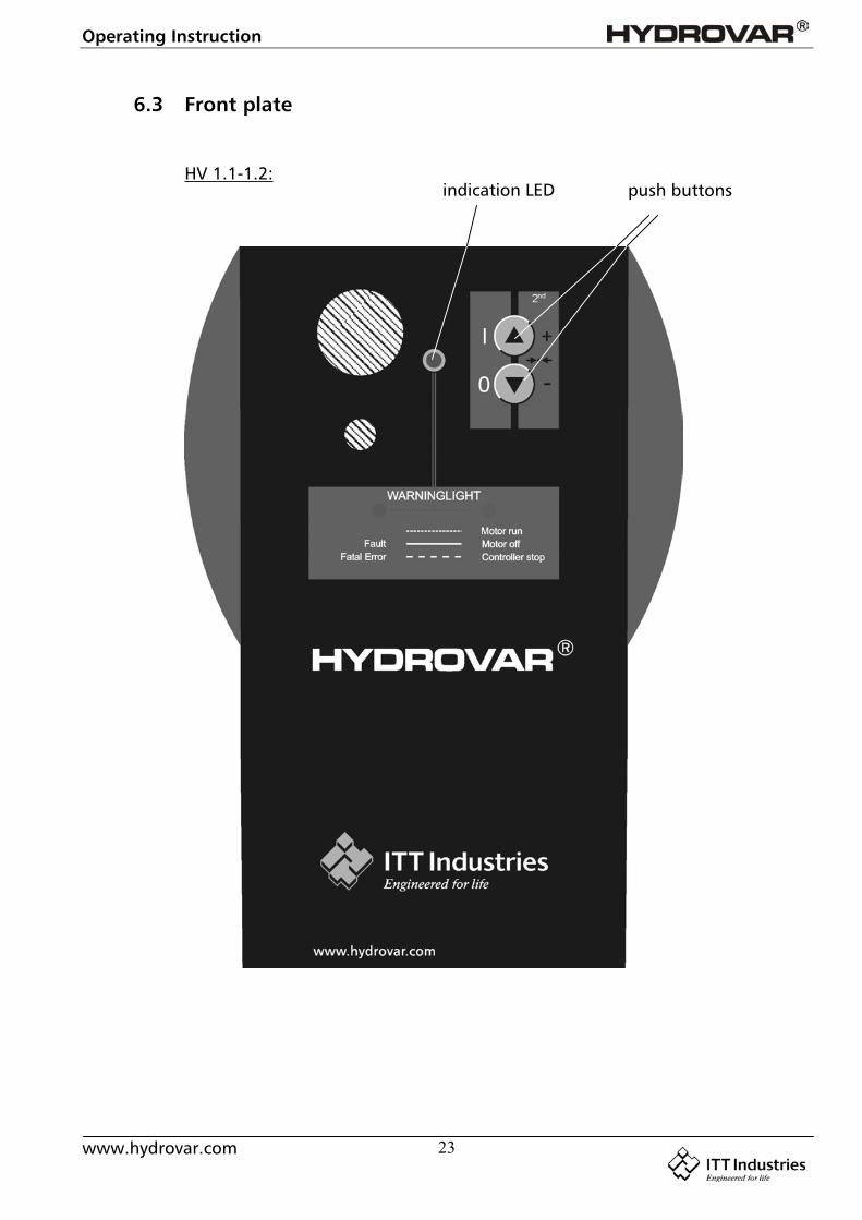
6.3 Front plate
HV 1.1-1.2:push buttonsindication LED
Operating Instruction
www.hydrovar.com 24
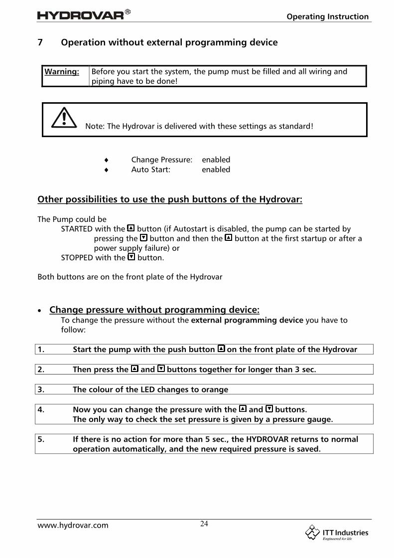
7 Operation without external programming device
Warning: Before you start the system, the pump must be filled and all wiring andpiping have to be done!
Change Pressure: enabled Auto Start: enabled
Other possibilities to use the push buttons of the Hydrovar:
The Pump could beSTARTED with the button (if Autostart is disabled, the pump can be started by
pressing the button and then the button at the first startup or after apower supply failure) or
STOPPED with the button.
Both buttons are on the front plate of the Hydrovar
Change pressure without programming device:To change the pressure without the external programming device you have tofollow:
1. Start the pump with the push button on the front plate of the Hydrovar
2. Then press the and buttons together for longer than 3 sec.
3. The colour of the LED changes to orange
4. Now you can change the pressure with the and buttons. The only way to check the set pressure is given by a pressure gauge.
5. If there is no action for more than 5 sec., the HYDROVAR returns to normal operation automatically, and the new required pressure is saved.
Note: The Hydrovar is delivered with these settings as standard!
Operating Instruction
www.hydrovar.com 25
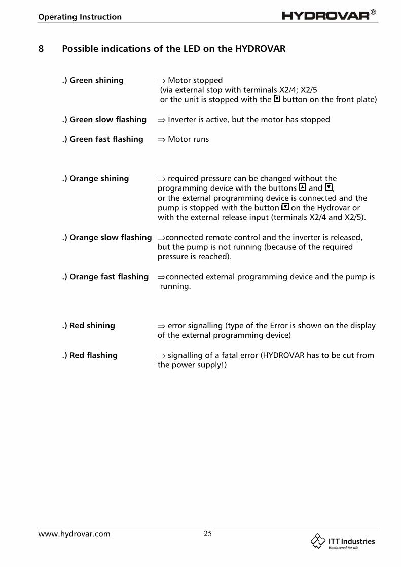
8 Possible indications of the LED on the HYDROVAR
.) Green shining Motor stopped (via external stop with terminals X2/4; X2/5 or the unit is stopped with the button on the front plate)
.) Green slow flashing Inverter is active, but the motor has stopped
.) Green fast flashing Motor runs
.) Orange shining required pressure can be changed without theprogramming device with the buttons and ,or the external programming device is connected and thepump is stopped with the button on the Hydrovar orwith the external release input (terminals X2/4 and X2/5).
.) Orange slow flashing connected remote control and the inverter is released,but the pump is not running (because of the requiredpressure is reached).
.) Orange fast flashing connected external programming device and the pump is running.
.) Red shining error signalling (type of the Error is shown on the displayof the external programming device)
.) Red flashing signalling of a fatal error (HYDROVAR has to be cut fromthe power supply!)
Operating Instruction
www.hydrovar.com 26
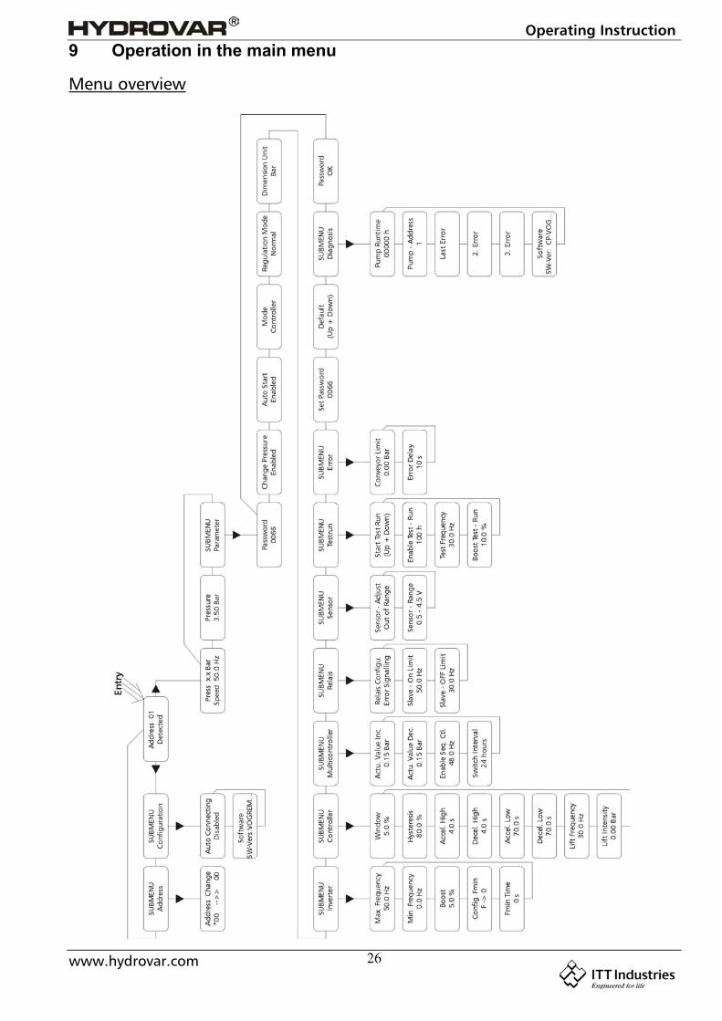
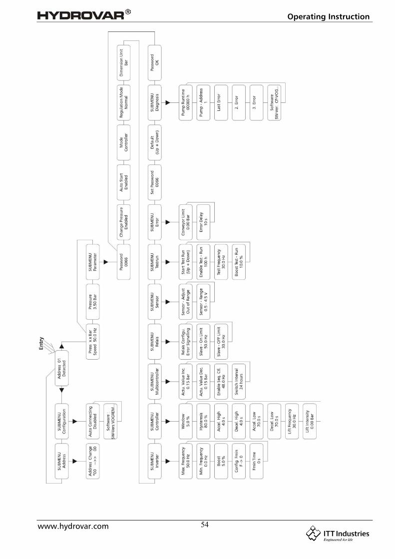
9 Operation in the main menu
Menu overview
Operating Instruction
www.hydrovar.com 27
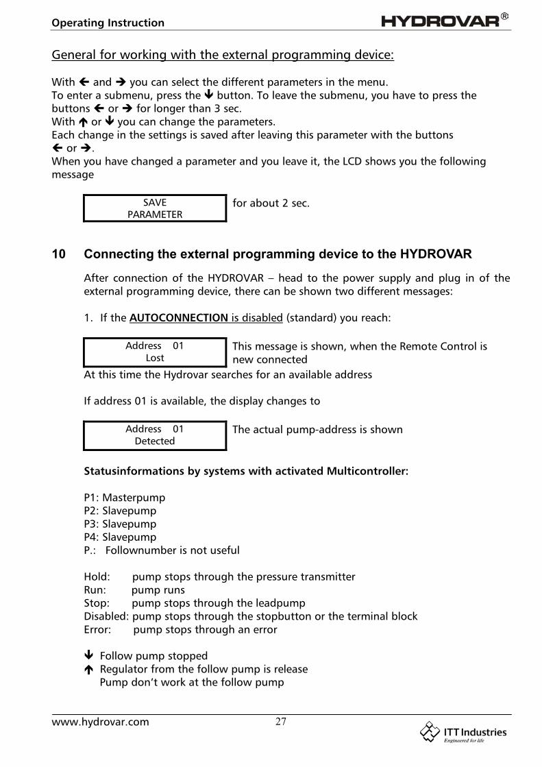
General for working with the external programming device:
With and you can select the different parameters in the menu.To enter a submenu, press the button. To leave the submenu, you have to press thebuttons or for longer than 3 sec.With or you can change the parameters.Each change in the settings is saved after leaving this parameter with the buttons or .When you have changed a parameter and you leave it, the LCD shows you the followingmessage
SAVEPARAMETER
for about 2 sec.
10 Connecting the external programming device to the HYDROVAR
After connection of the HYDROVAR – head to the power supply and plug in of theexternal programming device, there can be shown two different messages:
1. If the AUTOCONNECTION is disabled (standard) you reach:
Address 01Lost
This message is shown, when the Remote Control isnew connected
At this time the Hydrovar searches for an available address
If address 01 is available, the display changes to
Address 01Detected
The actual pump-address is shown
Statusinformations by systems with activated Multicontroller:
P1: MasterpumpP2: SlavepumpP3: SlavepumpP4: SlavepumpP.: Follownumber is not useful
Hold: pump stops through the pressure transmitterRun: pump runsStop: pump stops through the leadpumpDisabled: pump stops through the stopbutton or the terminal blockError: pump stops through an error
Follow pump stopped Regulator from the follow pump is release Pump don’t work at the follow pump
Operating Instruction
www.hydrovar.com 28
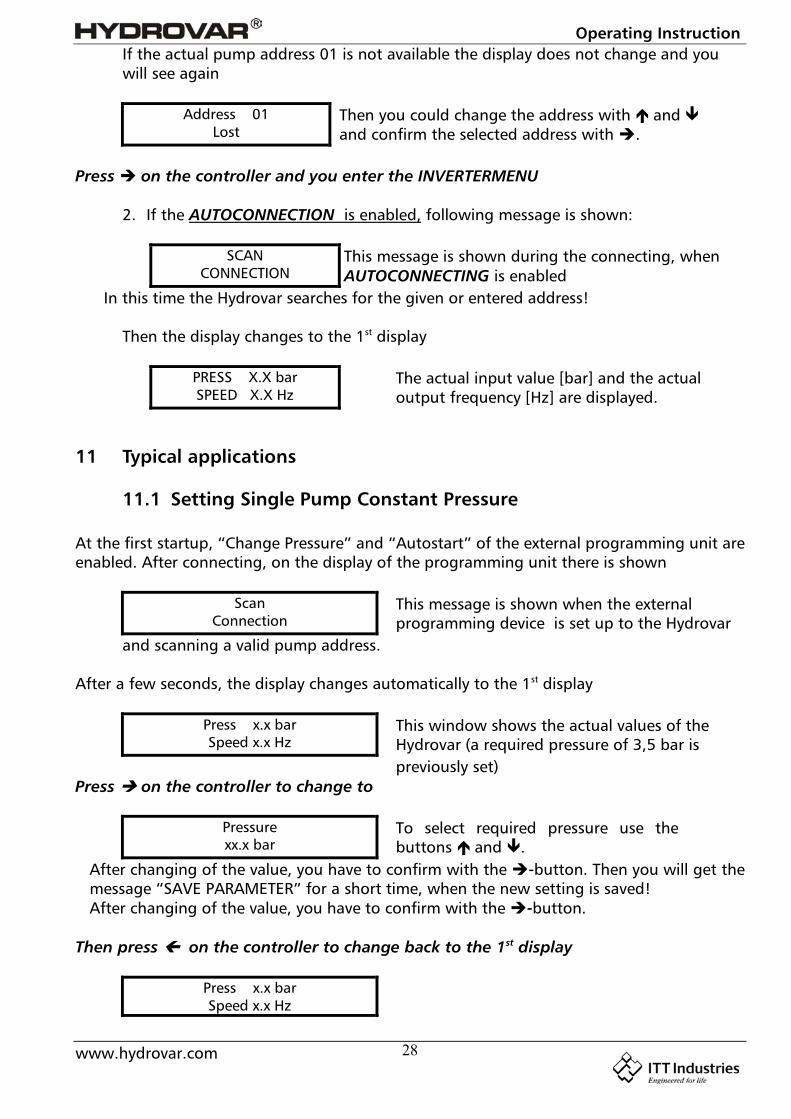
If the actual pump address 01 is not available the display does not change and youwill see again
Address 01Lost
Then you could change the address with and and confirm the selected address with .
Press on the controller and you enter the INVERTERMENU
2. If the AUTOCONNECTION is enabled, following message is shown:
SCANCONNECTION
This message is shown during the connecting, whenAUTOCONNECTING is enabled
In this time the Hydrovar searches for the given or entered address!
Then the display changes to the 1st display
PRESS X.X barSPEED X.X Hz
The actual input value [bar] and the actualoutput frequency [Hz] are displayed.
11 Typical applications
11.1 Setting Single Pump Constant Pressure
At the first startup, “Change Pressure” and “Autostart” of the external programming unit areenabled. After connecting, on the display of the programming unit there is shown
ScanConnection
This message is shown when the externalprogramming device is set up to the Hydrovar
and scanning a valid pump address.
After a few seconds, the display changes automatically to the 1st display
Press x.x barSpeed x.x Hz
This window shows the actual values of theHydrovar (a required pressure of 3,5 bar ispreviously set)
Press on the controller to change to
Pressurexx.x bar
To select required pressure use thebuttons and .
After changing of the value, you have to confirm with the -button. Then you will get themessage “SAVE PARAMETER” for a short time, when the new setting is saved!After changing of the value, you have to confirm with the -button.
Then press on the controller to change back to the 1st display
Press x.x barSpeed x.x Hz
Operating Instruction
www.hydrovar.com 29
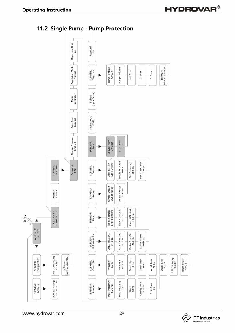
11.2 Single Pump - Pump Protection
Operating Instruction
www.hydrovar.com 30
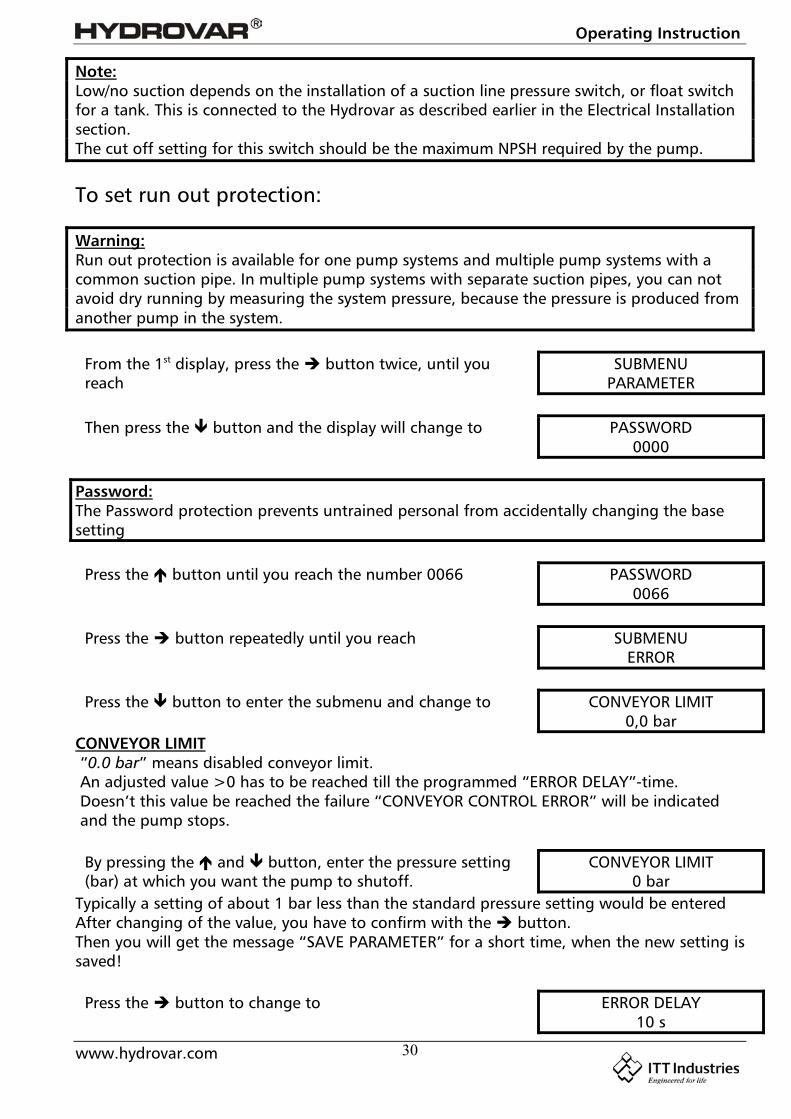
Note:Low/no suction depends on the installation of a suction line pressure switch, or float switchfor a tank. This is connected to the Hydrovar as described earlier in the Electrical Installationsection.The cut off setting for this switch should be the maximum NPSH required by the pump.
To set run out protection:
Warning:Run out protection is available for one pump systems and multiple pump systems with acommon suction pipe. In multiple pump systems with separate suction pipes, you can notavoid dry running by measuring the system pressure, because the pressure is produced fromanother pump in the system.
From the 1st display, press the button twice, until youreach
SUBMENUPARAMETER
Then press the button and the display will change to PASSWORD0000
Password:The Password protection prevents untrained personal from accidentally changing the basesetting
Press the button until you reach the number 0066 PASSWORD0066
Press the button repeatedly until you reach SUBMENUERROR
Press the button to enter the submenu and change to CONVEYOR LIMIT0,0 bar
CONVEYOR LIMIT“0.0 bar” means disabled conveyor limit.An adjusted value >0 has to be reached till the programmed “ERROR DELAY”-time.Doesn’t this value be reached the failure “CONVEYOR CONTROL ERROR” will be indicatedand the pump stops.
By pressing the and button, enter the pressure setting(bar) at which you want the pump to shutoff.
CONVEYOR LIMIT0 bar
Typically a setting of about 1 bar less than the standard pressure setting would be enteredAfter changing of the value, you have to confirm with the button.Then you will get the message “SAVE PARAMETER” for a short time, when the new setting issaved!
Press the button to change to ERROR DELAY10 s

Operating Instruction
www.hydrovar.com 31
ERROR DELAY:Adjustable between 0...100 sec.Delayed switch-off in the event of low water, terminal X2/6-X2/7) and also for the conveyorlimit.
By pressing the and button, you will be entering theamount of time (sec) that the pump will run at the
ERROR DELAY10 s
programmed conveyor limit before it automatically shuts off.After changing of the value, you have to confirm with the button. Then you will get themessage “SAVE PARAMETER” for a short time, when the new setting is saved!
Hold the button down for 3 seconds and you will bereturned to:
SUBMENUERROR
Hold the button down again for 3 seconds to return tothe 1st display
PRESSURE x.x barSPEED xx Hz
11.3 Single Pump – System Curve Compensation
The Hydrovar can automatically compensatefor system friction losses due to increasedflow. Tables are available in most pumpcatalogues indication the amount of frictionloss that can be expected in various sizes ofpumps at different flow rates. Use thesetables to determine the friction loss for thepipe size you are using at maximum flowrate.
This Diagram shows a typical system curve. The system pressure set point is shown at shutoffand pressure increase is shown for increasing flow.Calculate the pressure required to overcome friction loss at maximum flow.
Operating Instruction
www.hydrovar.com 32
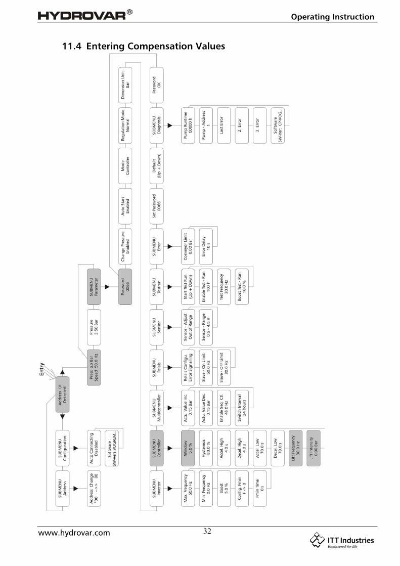
11.4 Entering Compensation Values
Operating Instruction
www.hydrovar.com 33
Instructions:
From the 1st display, press the button twice, until youreach
SUBMENUPARAMETER
Then press the button and the display will change to PASSWORD0000
Password:The Password protection prevents untrained personal from accidentally changing the basesetting
Press the button until you reach the number 0066 PASSWORD0066
Press the button repeatedly until you reach SUBMENUCONTROLLER
Press the button to enter the submenu and change to WINDOW5,0 %
Now press the button until you reach the parameter “LIFTFREQUENCY”
LIFT FREQUENCY30 Hz
LIFT FREQUENCY:This indicates the frequency at which the increase of the set pressure should begin.It should be the speed at which the pump works at the set pressure and at delivery rate of 0m³/h. On a 50 Hz system, there is virtually no flow below about 30 Hz, on a 60 Hz systemabout 40Hz.
Press the and button until you reach desired frequency. LIFT FREQUENCY30 Hz
After changing of the value, you have to confirm with the button.Then you will get the message “SAVE PARAMETER” for a short time, when the new setting issaved!
Now press the button to change to LIFT INTENSITY0,0 bar
LIFT INTENSITY:This value states, how much the required value should be continually increased, till themaximum speed (maximum volume) is reached.
Press the and button until you reach desired value LIFT INTENSITY0,0 bar
After changing of the value, you have to confirm with the button. Then you will get themessage “SAVE PARAMETER” for a short time, when the new setting is saved!
Hold the button down for 3 seconds to return to: SUBMENUCONTROLLER
Hold the button down again for 3 seconds to return tothe 1st display
PRESSURE x.x barSPEED xx Hz
Operating Instruction
www.hydrovar.com 34
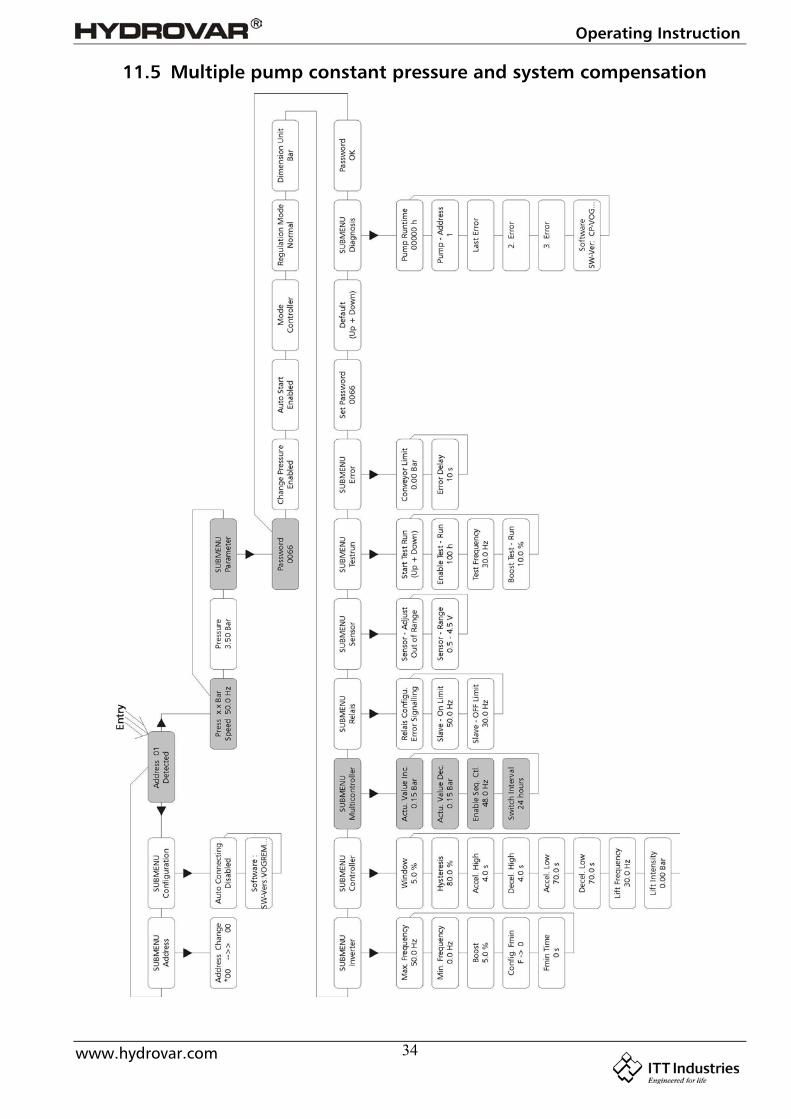
11.5 Multiple pump constant pressure and system compensation
Operating Instruction
www.hydrovar.com 35
When two, three or four Hydrovar speed controlled pumps are connected together in asystem via the RS485-interface, they can be programmed to work together to maintainsystem pressure up to the maximum flow rate of all the pumps combined.As the first pump reaches its maximum speed and flow, the second pump will automaticallyturn on (and so on). In addition, the sequence of the pump that will run first (lead pump)can be automatically varied to reduce premature wear on any one pump in the system.
Instructions:
!! Refer to chapter 11.1 (setting single pump constant pressure).Follow these instructions for setting the required pressure and then continuewith the following steps.
From the 1st display, press the button twice, until youreach
SUBMENUPARAMETER
Then press the button and the display will change to PASSWORD0000
Password:The Password protection prevents untrained personal from accidentally changing the basesetting
Press the button until you reach the number 0066 PASSWORD0066
Press the button repeatedly until you reach SUBMENUMULTICONTROLLER
Press the button to enter the submenu and change to ACTUAL VALUE INCREASE0.15 bar
ACTUAL PRESSURE INCREASE (= Lift value):This value, together with the fall value (ACTUAL VALUE DECREASE) determines the increaseof the required value after starting of the following pumps (see attached applicationexample on next page)
Operating Instruction
www.hydrovar.com 36
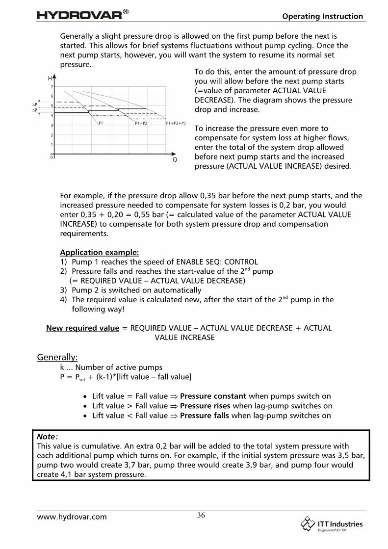
Generally a slight pressure drop is allowed on the first pump before the next isstarted. This allows for brief systems fluctuations without pump cycling. Once thenext pump starts, however, you will want the system to resume its normal setpressure.
For example, if the pressure drop allow 0,35 bar before the next pump starts, and theincreased pressure needed to compensate for system losses is 0,2 bar, you wouldenter 0,35 + 0,20 = 0,55 bar (= calculated value of the parameter ACTUAL VALUEINCREASE) to compensate for both system pressure drop and compensationrequirements.
Application example:1) Pump 1 reaches the speed of ENABLE SEQ: CONTROL2) Pressure falls and reaches the start-value of the 2nd pump
(= REQUIRED VALUE – ACTUAL VALUE DECREASE)3) Pump 2 is switched on automatically4) The required value is calculated new, after the start of the 2nd pump in the
following way!
New required value = REQUIRED VALUE – ACTUAL VALUE DECREASE + ACTUAL VALUE INCREASE
Generally:k ... Number of active pumpsP = Pset + (k-1)*[lift value – fall value]
Lift value = Fall value Pressure constant when pumps switch on Lift value > Fall value Pressure rises when lag-pump switches on Lift value < Fall value Pressure falls when lag-pump switches on
Note:This value is cumulative. An extra 0,2 bar will be added to the total system pressure witheach additional pump which turns on. For example, if the initial system pressure was 3,5 bar,pump two would create 3,7 bar, pump three would create 3,9 bar, and pump four wouldcreate 4,1 bar system pressure.
To do this, enter the amount of pressure dropyou will allow before the next pump starts(=value of parameter ACTUAL VALUEDECREASE). The diagram shows the pressuredrop and increase.
To increase the pressure even more tocompensate for system loss at higher flows,enter the total of the system drop allowedbefore next pump starts and the increasedpressure (ACTUAL VALUE INCREASE) desired.
Operating Instruction
www.hydrovar.com 37
Enter the required value by pressing the and button ACTUAL VALUE INCREASE0,15 bar
After changing of the value, you have to confirm with the button.Then you will get the message “SAVE PARAMETER” for a short time, when the new setting issaved!
Press the button to change to ACTUAL VALUE DECREASE0,15 bar
ACTUAL PRESSURE DECREASE (= Fall value):This value determines amount of pressure drop you will allow before the next pump starts.
(see application example on previous page)
Enter the required value by pressing the and button ACTUAL VALUE DECREASE0,15 bar
After changing of the value, you have to confirm with the button.Then you will get the message “SAVE PARAMETER” for a short time, when the new setting issaved!
Press the button to change to ENABLE SEQ. CONTROL48 Hz
ENABLE SEQUENCE CONTROL:The follow-up pump only starts, when the start-value is reached and the lead pump hasreached the programmed release-frequency. (Adjustable from 0.0 Hz to 70 Hz). Normallythis start frequency is set 1 to 2Hz lower than the MAX. FREQUENCYIf you don’t want to start a following pump this value has to be set higher than the MAX.FREQUENCY. (see application example on previous page)
Enter the required value by pressing the and button ENABLE SEQ. CONTROL49 Hz
After changing of the value, you have to confirm with the button.Then you will get the message “SAVE PARAMETER” for a short time, when the new setting issaved!
Press the button to change to SWITCH INTERVAL24 HOURS
SWITCH INTERVALThis time determines the interval of the changeover of the master pump in order to achieveeven operating hours of all pumps in the system. Adjustable between 0 and 250 hours
Enter the required value by pressing the and button SWITCH INTERVAL24 HOURS
Operating Instruction
www.hydrovar.com 38
After changing of the value, you have to confirm with the button.Then you will get the message “SAVE PARAMETER” for a short time, when the new setting issaved!
Use the settings of this submenu (lift value, fall value, enable sequence control andswitch interval) for each pump in the Hydrovar system
Hold the button down for 3 seconds to return to: SUBMENUCONTROLLER
Hold the button down again for 3 seconds to return tothe 1st display
PRESSURE x.x barSPEED xx Hz
If you set the addresses in a multiple pump system the first time, connect only theHydrovar unit where you want to set the address to power supply otherwise allHydrovars in the system connected over the RS485-interface will change theiraddress, too
In the following section you will give the pump an address number. Generally, the firstprogrammed pump will be number 1, the second will be number 2, and so on. The purposeof this is to help the Hydrovar sequence the start and stop activity of the pumps in thesystem including the selection of the lead and lag pumps.
From the 1st display, hold the button for longer than 3sec. to get the display, where the actual address is shown
Address 01Detected
orWhen there is no active address, there is shown Address 01
L O S T
Then press the button twice to change to SubmenuAddress
Press the button to enter the submenu and change to Address Change00 --> 00 *
Addresses from 01 to 04 and also 00 can be set in this parameter. To change the addressit is not necessary to cut the interface connection to other HYDROVARS.On the left side there is shown the address of the HYDROVAR, which you are actuallyspeaking (select the address by using the buttons or ). On the right side, then you cangive the HYDROVAR a new address also with the buttons and . You only can give anaddress, which is not used in the pump group!To change between left and right side, press button or . The star shows the actualused side.
To save the new selected address press both buttons ( and ) together for 2 sec. If itwas successfully you will see the same address on both sides.

Operating Instruction
www.hydrovar.com 39
Example:To change the Hydrovar with address 01 to address 04:
press the button to change the * to the left side Address Change00* --> 00
Select the address of the Hydrovar, you want to change theaddress with the and button
Address Change01* --> 00
press the button to change the * to the right side Address Change01 --> 00*
Select the address you want to give this Hydrovar with the and button
Address Change01 --> 04*
To confirm and save the new selected address press both buttons (and ) together for2 sec. If it was successfully you will see the same address on both sides.
Address Change04 --> 04*
The definition of the address you have to do for each pump in the system.
Hold the button down for 3 seconds to return to: SUBMENUAddress
Hold the button down again for 3 seconds to return tothe 1st display
PRESSURE x.x barSPEED xx Hz
12 Settings at the Invertermenu
1st display PRESS X.X barSPEED X.X Hz
The actual input value [bar] and the actualoutput frequency [Hz] are displayed.
Press on the controller to change to
PRESSUREXX.X bar
There you can set required pressurewith the buttons and
Press on the controller to change to
SUBMENUPARAMETER
To enter the submenu “Parameter”,press button
Press on the controller to change to 1st display
Operating Instruction
www.hydrovar.com 40
13 Settings at the Submenu-Parameter
Warning: Before entering the secondary menu these instructionsmust be read carefully to prevent incorrect settings which willcause malfunction.
After entering the SUBMENU PARAMETER, the display
... will change toPASSWORD
0000
Set Password 0066 by pressing and PASSWORD
0066
Confirm by pressing and the firstparameter of the sub menu is shown
Change PressureEnabled
13.1 Pressure change
Change PressureEnabled
You can decide between (Enabled) or (Disabled)
If the pressure setting is enabled, you can change the required pressure on theHydrovarhead with decrease and increase (see chapter 7) without an externalprogramming device.
Press on the controller to change to
13.2 Auto start
Auto StartEnabled
You can select between Disabled and Enabled
Autostart Enabled means, that the pump starts again automatically after an interruptionof the power supply (power failure).If Autostart Disabled is set, the pump has to be restarted manually after a power failure,by pressing and .
Press on the controller to change to
13.3 Mode
Note: The password must be entered at each entry

Operating Instruction
www.hydrovar.com 41
ModeController
Select with buttons and between: Multicontroller sequence control for max. 4 pumps
Controller pressure control for a single pump If only one HYDROVAR-pump is inoperation, set Controller.If more than one HYDROVAR-pumps are working together via the RS485-interface, theMulticontroller must be selected.Actuator external frequency setting. The application Actuator is only used, if youhave an external controller and the HYDROVAR works like a standard frequencyconverter (external frequency signal 0,5-4,5VDC to the terminals X2/1 and X2/2).
Press on the controller to change to
13.4 Control Response
Regulation ModeNormal
Normal: Speed is increased with falling actual valueSignals. (e.g.: Control at constant output pressure).Inverse: Speed is reduced with falling actual valuesignal, (e.g.: Control of constant suction pressure or atconstant level before the pump).
Press on the controller to change to
13.4.1 Dimension unit
Dimension unitBar
Here you could choose your favourite unit (withbuttons and ) Bar, psi or % for the 1st display.
Press on the controller to change to
13.5 Submenu Inverter
SubmenuInverter
To enter this menu you have to press the key, toleave the menu, press the key longer than 3 sec.
Press on the controller to change to
13.5.1 Maximum Frequency
Max. Frequency50.0 Hz
Possible setting between min. 40 and max. 70 Hz.Attention: Settings higher than 50 Hz may overload themotor!Settings of 10% above nominal frequency cause 33%more power consumption!
Press on the controller to change to
Operating Instruction
www.hydrovar.com 42
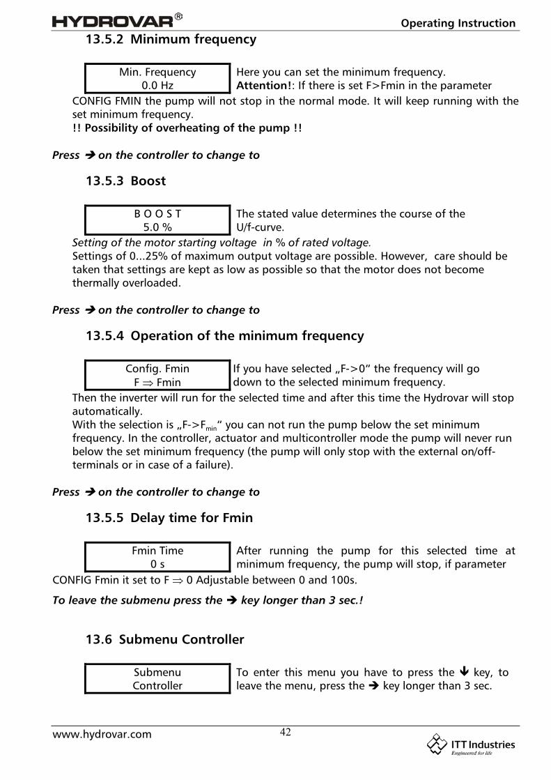
13.5.2 Minimum frequency
Min. Frequency0.0 Hz
Here you can set the minimum frequency.Attention!: If there is set F>Fmin in the parameter
CONFIG FMIN the pump will not stop in the normal mode. It will keep running with theset minimum frequency.!! Possibility of overheating of the pump !!
Press on the controller to change to
13.5.3 Boost
B O O S T5.0 %
The stated value determines the course of theU/f-curve.
Setting of the motor starting voltage in % of rated voltage.Settings of 0...25% of maximum output voltage are possible. However, care should betaken that settings are kept as low as possible so that the motor does not becomethermally overloaded.
Press on the controller to change to
13.5.4 Operation of the minimum frequency
Config. FminF Fmin
If you have selected „F->0“ the frequency will godown to the selected minimum frequency.
Then the inverter will run for the selected time and after this time the Hydrovar will stopautomatically.With the selection is „F->Fmin“ you can not run the pump below the set minimumfrequency. In the controller, actuator and multicontroller mode the pump will never runbelow the set minimum frequency (the pump will only stop with the external on/off-terminals or in case of a failure).
Press on the controller to change to
13.5.5 Delay time for Fmin
Fmin Time0 s
After running the pump for this selected time atminimum frequency, the pump will stop, if parameter
CONFIG Fmin it set to F 0 Adjustable between 0 and 100s.
To leave the submenu press the key longer than 3 sec.!
13.6 Submenu Controller
SubmenuController
To enter this menu you have to press the key, toleave the menu, press the key longer than 3 sec.
Operating Instruction
www.hydrovar.com 43
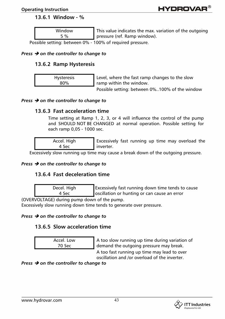
13.6.1 Window - %
Window5 %
This value indicates the max. variation of the outgoingpressure (ref. Ramp window).
Possible setting: between 0% - 100% of required pressure.
Press on the controller to change to
13.6.2 Ramp Hysteresis
Hysteresis80%
Level, where the fast ramp changes to the slowramp within the window.Possible setting: between 0%..100% of the window
Press on the controller to change to
13.6.3 Fast acceleration timeTime setting at Ramp 1, 2, 3, or 4 will influence the control of the pumpand SHOULD NOT BE CHANGED at normal operation. Possible setting foreach ramp 0,05 - 1000 sec.
Accel. High4 Sec
Excessively fast running up time may overload theinverter.
Excessively slow running up time may cause a break down of the outgoing pressure.
Press on the controller to change to
13.6.4 Fast deceleration time
Decel. High4 Sec
Excessively fast running down time tends to causeoscillation or hunting or can cause an error
(OVERVOLTAGE) during pump down of the pump.Excessively slow running down time tends to generate over pressure.
Press on the controller to change to
13.6.5 Slow acceleration time
Accel. Low70 Sec
A too slow running up time during variation ofdemand the outgoing pressure may break.A too fast running up time may lead to overoscillation and /or overload of the inverter.
Press on the controller to change to

Operating Instruction
www.hydrovar.com 44
13.6.6 Slow deceleration time
Decel. Low70 Sec
A too fast setting leads to oscillationA too slow setting delays the switching off toomuch and may generate over pressure.
Ramp Window
Press on the controller to change to
13.6.7 Compensation FrequencyControl according to a system curve (increase of the set pressure depending on thedelivery rate or speed).
LIFT FREQUENCY30.0 Hz
Adjustable between 6 Hz and the set MAXIMUMFREQUENCY, this setting states at which frequency
the set pressure should be increased. That is the speed at which the pump works at the setpressure and at delivery rate 0.
Press on the controller to change to
13.6.8 Lift-IntensityLIFT – INTENS.
0.0 barAdjustable from 0 to 100% of the range of the usedpressure transmitter.
This value states how much the required value should be continually increased, till themaximum speed (maximum volume) is reached.
Operating Instruction
www.hydrovar.com 45
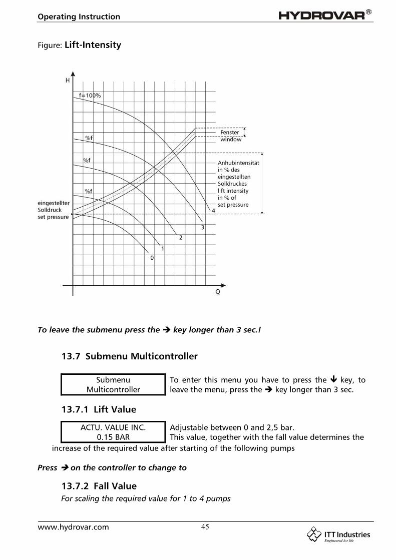
Figure: Lift-Intensity
To leave the submenu press the key longer than 3 sec.!
13.7 Submenu Multicontroller
SubmenuMulticontroller
To enter this menu you have to press the key, toleave the menu, press the key longer than 3 sec.
13.7.1 Lift Value
ACTU. VALUE INC.0.15 BAR
Adjustable between 0 and 2,5 bar.This value, together with the fall value determines the
increase of the required value after starting of the following pumps
Press on the controller to change to
13.7.2 Fall ValueFor scaling the required value for 1 to 4 pumps
Operating Instruction
www.hydrovar.com 46
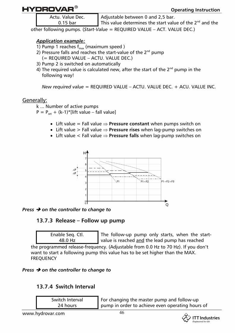
Actu. Value Dec.0.15 bar
Adjustable between 0 and 2,5 bar.This value determines the start value of the 2nd and the
other following pumps. (Start-Value = REQUIRED VALUE – ACT. VALUE DEC.)
Application example:1) Pump 1 reaches fmax (maximum speed )2) Pressure falls and reaches the start-value of the 2nd pump
(= REQUIRED VALUE – ACTU. VALUE DEC.)3) Pump 2 is switched on automatically4) The required value is calculated new, after the start of the 2nd pump in the
following way!
New required value = REQUIRED VALUE – ACTU. VALUE DEC. + ACU. VALUE INC.
Generally:k ... Number of active pumpsP = Pset + (k-1)*[lift value – fall value]
Lift value = Fall value Pressure constant when pumps switch on Lift value > Fall value Pressure rises when lag-pump switches on Lift value < Fall value Pressure falls when lag-pump switches on
Press on the controller to change to
13.7.3 Release – Follow up pump
Enable Seq. Ctl.48.0 Hz
The follow-up pump only starts, when the start-value is reached and the lead pump has reached
the programmed release-frequency. (Adjustable from 0.0 Hz to 70 Hz). If you don’twant to start a following pump this value has to be set higher than the MAX.FREQUENCY
Press on the controller to change to
13.7.4 Switch Interval
Switch Interval24 hours
For changing the master pump and follow-uppump in order to achieve even operating hours of

Operating Instruction
www.hydrovar.com 47
the pumps. Adjustable between 0 and 250 hours
To leave the submenu press the key longer than 3 sec.!
13.8 Submenu Relay
SubmenuRelay
To enter this menu you have to press the key, toleave the menu, press the key longer than 3 sec.
13.8.1 Relay Configuration
Relay Configu.Simple Multicnt.
Possible selections with buttons and :Simple Multicnt. allows to start a following(simple multi- constant speed pump. controller)Run Signalling Run indication over the relayError Signalling fault indication over the relay
Warning: Max. contact load 500mA / 125V
Press on the controller to change to
13.8.2 Start frequency of the slave pump
Slave-On Limit50,0 Hz
Here you can set the frequency of the speedcontrolled HYDROVAR-pump, when the full speed
slave pump should start, if “simple multicontroller” is set in the parameter Relayconfiguration. In this case, the slave pump runs with full speed and the HYDROVAR-pump controls the additional demand.
Press on the controller to change to
13.8.3 Stop frequency of the slave pump
Slave-Off Limit30.0 Hz
Here you can set the frequency of the speedcontrolled HYDROVAR-pump, where the full speed
slave pump should stop, if “simple multicontroller” is set in the parameter Relayconfiguration.
To leave the submenu press the key longer than 3 sec.!
13.9 Submenu Sensor
SubmenuSensor
To enter this menu you have to press the key, toleave the menu, press the key longer than 3 sec.
Operating Instruction
www.hydrovar.com 48
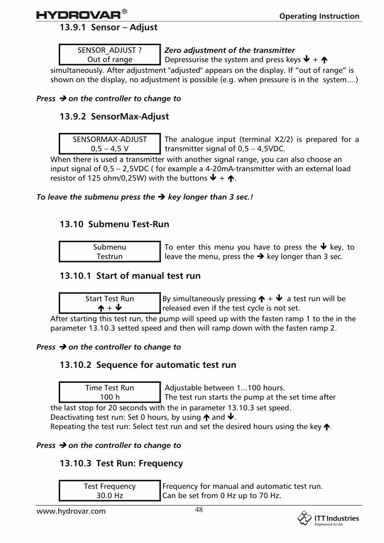
13.9.1 Sensor – Adjust
SENSOR_ADJUST ?Out of range
Zero adjustment of the transmitterDepressurise the system and press keys +
simultaneously. After adjustment "adjusted" appears on the display. If “out of range” isshown on the display, no adjustment is possible (e.g. when pressure is in the system....)
Press on the controller to change to
13.9.2 SensorMax-Adjust
SENSORMAX-ADJUST0,5 – 4,5 V
The analogue input (terminal X2/2) is prepared for atransmitter signal of 0,5 – 4,5VDC.
When there is used a transmitter with another signal range, you can also choose aninput signal of 0,5 – 2,5VDC ( for example a 4-20mA-transmitter with an external loadresistor of 125 ohm/0,25W) with the buttons + .
To leave the submenu press the key longer than 3 sec.!
13.10 Submenu Test-Run
SubmenuTestrun
To enter this menu you have to press the key, toleave the menu, press the key longer than 3 sec.
13.10.1 Start of manual test run
Start Test Run +
By simultaneously pressing + a test run will bereleased even if the test cycle is not set.
After starting this test run, the pump will speed up with the fasten ramp 1 to the in theparameter 13.10.3 setted speed and then will ramp down with the fasten ramp 2.
Press on the controller to change to
13.10.2 Sequence for automatic test run
Time Test Run100 h
Adjustable between 1...100 hours.The test run starts the pump at the set time after
the last stop for 20 seconds with the in parameter 13.10.3 set speed.Deactivating test run: Set 0 hours, by using and .Repeating the test run: Select test run and set the desired hours using the key .
Press on the controller to change to
13.10.3 Test Run: Frequency
Test Frequency30.0 Hz
Frequency for manual and automatic test run.Can be set from 0 Hz up to 70 Hz.

Operating Instruction
www.hydrovar.com 49
Press on the controller to change to
13.10.4 Test Run: Boost
BOOST Test Run10.0 %.
Start voltage in % of rated voltage in order to ensurethat the motor starts safely. Adjustable between 0%and 25%
To leave the submenu press the key longer than 3 sec.!
13.11 Submenu ErrorSubmenu
ErrorTo enter this menu you have to press the key, toleave the menu, press the key longer than 3 sec.
13.11.1 Conveyor LimitConveyor Limit
0.0 barDisabled or adjustable between 0 and 10 bar of theanalogue input signal range.
“0.0 bar” means disabled conveyor limit.An adjusted value >0 has to be reached till the programmed “ERROR DELAY”-time.Doesn’t this value be reached the failure “ERROR WATER” will be indicated and thepump stops.
Press on the controller to change to
13.11.2 Error DelayError Delay
10 Sec.Adjustable between 0...100 sec.Delayed switch-off in the event of low water,
(Terminal X2/6-X2/7) and also for the conveyor limit.
To leave the submenu press the key for 3 sec.!
13.12 Set Password
Set Password0066
The pre-set password can be changed if necessarywith the and keys.
Press on the controller to change to
13.13 Default Settings
Default +
To load DEFAULT – PARAMETER, press buttons + together, till the timer is run down.
Press on the controller to change to
13.14 Submenu DiagnosisSubmenuDiagnosis
To enter this menu you have to press the key, toleave the menu, press the key longer than 3 sec.
Operating Instruction
www.hydrovar.com 50
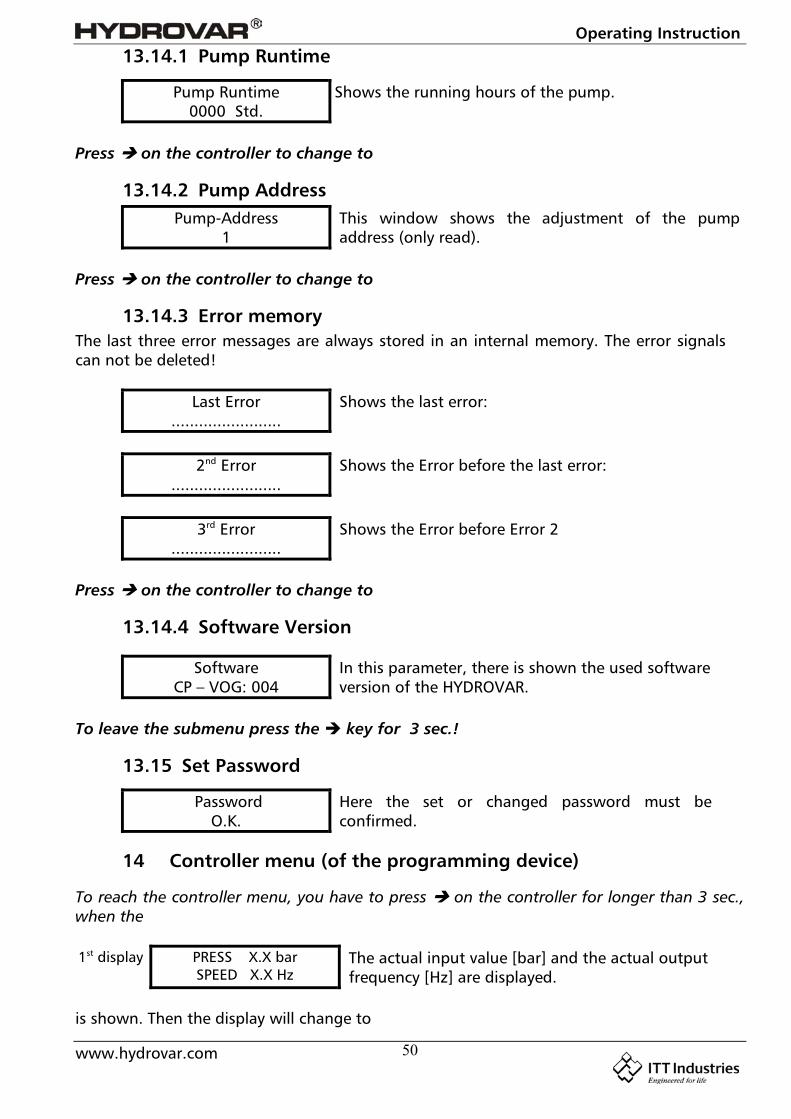
13.14.1 Pump Runtime
Pump Runtime0000 Std.
Shows the running hours of the pump.
Press on the controller to change to
13.14.2 Pump AddressPump-Address
1This window shows the adjustment of the pumpaddress (only read).
Press on the controller to change to
13.14.3 Error memoryThe last three error messages are always stored in an internal memory. The error signalscan not be deleted!
Last Error........................
Shows the last error:
2nd Error........................
Shows the Error before the last error:
3rd Error........................
Shows the Error before Error 2
Press on the controller to change to
13.14.4 Software Version
SoftwareCP – VOG: 004
In this parameter, there is shown the used softwareversion of the HYDROVAR.
To leave the submenu press the key for 3 sec.!
13.15 Set Password
PasswordO.K.
Here the set or changed password must beconfirmed.
14 Controller menu (of the programming device)
To reach the controller menu, you have to press on the controller for longer than 3 sec.,when the
1st display PRESS X.X barSPEED X.X Hz
The actual input value [bar] and the actual outputfrequency [Hz] are displayed.
is shown. Then the display will change to
Operating Instruction
www.hydrovar.com 51
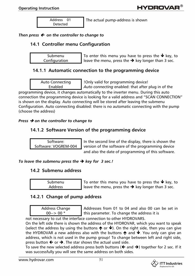
Address 01Detected
The actual pump-address is shown
Then press on the controller to change to
14.1 Controller menu Configuration
SubmenuConfiguration
To enter this menu you have to press the key, toleave the menu, press the key longer than 3 sec.
14.1.1 Automatic connection to the programming device
Auto ConnectingEnabled
!Only valid for programming device!Auto connecting enabled: that after plug in of the
programming device, it changes automatically to the inverter menu. During this autoconnection the programming device is looking for a valid address and “SCAN CONNECTION”is shown on the display. Auto connecting will be stored after leaving the submenuConfiguration. Auto connecting disabled: there is no automatic connecting with the pump(choose the address)
Press on the controller to change to
14.1.2 Software Version of the programming device
Software:Software: VOGREM-004
In the second line of the display, there is shown theversion of the software of the programming deviceand also the date of programming of this software.
To leave the submenu press the key for 3 sec.!
14.2 Submenu address
SubmenuAddress
To enter this menu you have to press the key, toleave the menu, press the key longer than 3 sec.
14.2.1 Change of pump address
Address Change00--> 00 *
Addresses from 01 to 04 and also 00 can be set inthis parameter. To change the address it is
not necessary to cut the interface connection to other HYDROVARS.On the left side there is shown the address of the HYDROVAR, which you want to speak(select the address by using the buttons or ). On the right side, then you can givethe HYDROVAR a new address also with the buttons and . You only can give anaddress, which is not used in the pump group! To change between left and right side,press button or . The star shows the actual used side.To save the new selected address press both buttons ( and ) together for 2 sec. If itwas successfully you will see the same address on both sides.
Operating Instruction
www.hydrovar.com 52
To leave the submenu press the key for 3 sec.!
15 Possible Error messages
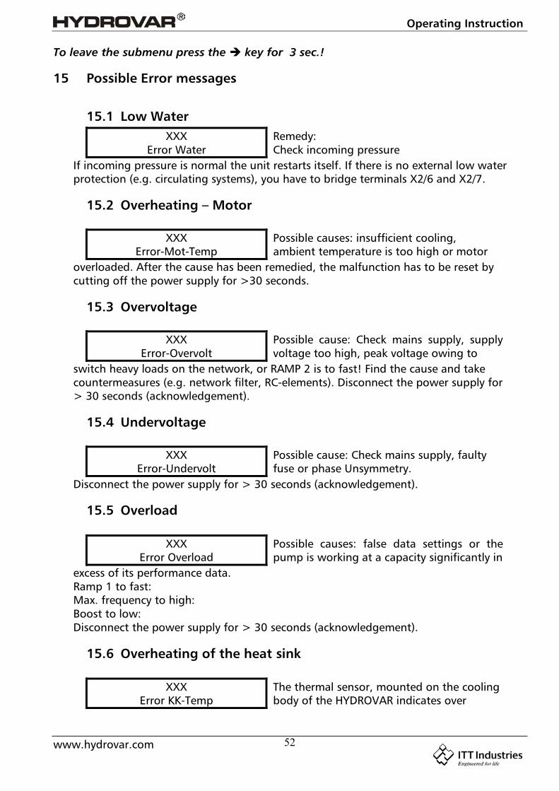
15.1 Low WaterXXX
Error WaterRemedy:Check incoming pressure
If incoming pressure is normal the unit restarts itself. If there is no external low waterprotection (e.g. circulating systems), you have to bridge terminals X2/6 and X2/7.
15.2 Overheating – Motor
XXXError-Mot-Temp
Possible causes: insufficient cooling,ambient temperature is too high or motor
overloaded. After the cause has been remedied, the malfunction has to be reset bycutting off the power supply for >30 seconds.
15.3 Overvoltage
XXXError-Overvolt
Possible cause: Check mains supply, supplyvoltage too high, peak voltage owing to
switch heavy loads on the network, or RAMP 2 is to fast! Find the cause and takecountermeasures (e.g. network filter, RC-elements). Disconnect the power supply for> 30 seconds (acknowledgement).
15.4 Undervoltage
XXXError-Undervolt
Possible cause: Check mains supply, faultyfuse or phase Unsymmetry.
Disconnect the power supply for > 30 seconds (acknowledgement).
15.5 Overload
XXXError Overload
Possible causes: false data settings or thepump is working at a capacity significantly in
excess of its performance data.Ramp 1 to fast:Max. frequency to high:Boost to low:Disconnect the power supply for > 30 seconds (acknowledgement).
15.6 Overheating of the heat sink
XXXError KK-Temp
The thermal sensor, mounted on the coolingbody of the HYDROVAR indicates over
Operating Instruction
www.hydrovar.com 53
temperature. Possible causes: insufficient cooling, ambient temperature is too high ormotor overloaded. After the cause has been remedied, the malfunction has to be resetby cutting off the power supply for >30 seconds.
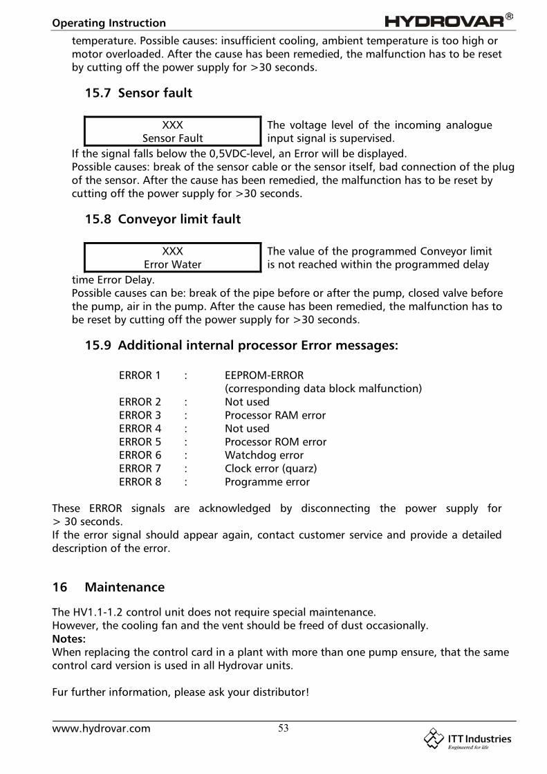
15.7 Sensor fault
XXXSensor Fault
The voltage level of the incoming analogueinput signal is supervised.
If the signal falls below the 0,5VDC-level, an Error will be displayed.Possible causes: break of the sensor cable or the sensor itself, bad connection of the plugof the sensor. After the cause has been remedied, the malfunction has to be reset bycutting off the power supply for >30 seconds.
15.8 Conveyor limit fault
XXXError Water
The value of the programmed Conveyor limitis not reached within the programmed delay
time Error Delay.Possible causes can be: break of the pipe before or after the pump, closed valve beforethe pump, air in the pump. After the cause has been remedied, the malfunction has tobe reset by cutting off the power supply for >30 seconds.
15.9 Additional internal processor Error messages:
ERROR 1 : EEPROM-ERROR(corresponding data block malfunction)
ERROR 2 : Not usedERROR 3 : Processor RAM errorERROR 4 : Not usedERROR 5 : Processor ROM errorERROR 6 : Watchdog errorERROR 7 : Clock error (quarz)ERROR 8 : Programme error
These ERROR signals are acknowledged by disconnecting the power supply for> 30 seconds.If the error signal should appear again, contact customer service and provide a detaileddescription of the error.
16 Maintenance
The HV1.1-1.2 control unit does not require special maintenance.However, the cooling fan and the vent should be freed of dust occasionally.Notes:When replacing the control card in a plant with more than one pump ensure, that the samecontrol card version is used in all Hydrovar units.
Fur further information, please ask your distributor!
Operating Instruction
www.hydrovar.com 54
Operating Instruction
www.hydrovar.com 55
Manufacturer's Declarationas defined in EC Machinery Directive 98/392/EEC,Appendix II Band the EMC Directive 89/336/EEC
We herewith declare that the frequency converter of type
HDROVAR HV 1.1, 1.15, 1.2
is intended for assembly with other machines to a machine. It is forbidden to start using ituntil it has been established that the machine on this converter is to be installed or withwhich this converter is to be assembled complies with the provisions of EC Directives93/44/EEC and 93/68/EEC.
Relevant technical standards and specifications, especially
EN 55011EN 50082-2EN 60146EN 50178
EN 60204-1
.........................................................Dir. Ing. SacherPumpenfabrik ERNST VOGEL GmbH
A-2000 Stockerau, Ernst Vogel-Str. 2
Stockerau, 25.03.03

Operating Instruction
www.hydrovar.com 56
Pumpenfabrik ERNST Vogel GmbH
A-2000 StockerauErnst Vogel-Strasse 2Telefon: 02266/604Telefax: 02266/65 311Internet: www.vogel-pumpen.com
www.hydrovar.com
A-8054 Graz SeiersbergKärtnerstrasse 518Telefon: 0316/28 6120Telefax: 0316/28 70 42
A-9020 KlagenfurtSchachterlweg 58Telefon: 0463/31 93 20Telefax: 0463/31 93 17
A-4600 WelsHaidestrasse 41Telefon: 07242/66 8 51,52,53,54Telefax: 07242/66 8 51/12
A-6175 KematenBahnhofstrasse 31Telefon: 05232/20 0 01Telefax: 05232/20 0 03
LOWARA-VOGEL Szivattyú Kft.H-8000 SzékesfehérvárBakony u. 8Telefon: 0036/22/512 640Telefax: 0036/22/512 642
Lowara Vogel Polska sp.zo.o.PL-40652 Katowice, ul. Worcella 16Telefon: 0048/32/202 8904Telefax: 0048/32/202 5452
VOGEL-ROCANO SACH-2087 Cornaux, Z.I. Prés-BersotTelefon: 0041/32/75 87 200Telefax: 0041/32/75 87 200
Tochterunternehmen in EuropaSubsidiaries in Europa