Embed Size (px)
Citation preview

Operating Instructions and Parts Manual 16-inch Open-End Belt Sander Model 1632
Powermatic 427 New Sanford Road LaVergne, Tennessee 37086 Part No. M-0460219 Ph.: 800-274-6848 Revision H2 01/2017 www.powermatic.com Copyright © 2017 Powermatic

2
1.0 Warranty and Service Powermatic warrants every product it sells against manufacturers’ defects. If one of our tools needs service or repair, please contact Technical Service by calling 1-800-274-6846, 8AM to 5PM CST, Monday through Friday.
Warranty Period The general warranty lasts for the time period specified in the literature included with your product or on the official Powermatic branded website.
• Powermatic products carry a limited warranty which varies in duration based upon the product. (See chart below)
• Accessories carry a limited warranty of one year from the date of receipt. • Consumable items are defined as expendable parts or accessories expected to become inoperable within a
reasonable amount of use and are covered by a 90 day limited warranty against manufacturer’s defects.
Who is Covered This warranty covers only the initial purchaser of the product from the date of delivery.
What is Covered This warranty covers any defects in workmanship or materials subject to the limitations stated below. This warranty does not cover failures due directly or indirectly to misuse, abuse, negligence or accidents, normal wear-and-tear, improper repair, alterations or lack of maintenance. Powermatic woodworking machinery is designed to be used with Wood. Use of these machines in the processing of metal, plastics, or other materials may void the warranty. The exceptions are acrylics and other natural items that are made specifically for wood turning.
Warranty Limitations Woodworking products with a Five Year Warranty that are used for commercial or industrial purposes default to a Two Year Warranty. Please contact Technical Service at 1-800-274-6846 for further clarification.
How to Get Technical Support Please contact Technical Service by calling 1-800-274-6846. Please note that you will be asked to provide proof of initial purchase when calling. If a product requires further inspection, the Technical Service representative will explain and assist with any additional action needed. Powermatic has Authorized Service Centers located throughout the United States. For the name of an Authorized Service Center in your area call 1-800-274-6846 or use the Service Center Locator on the Powermatic website.
More Information Powermatic is constantly adding new products. For complete, up-to-date product information, check with your local distributor or visit the Powermatic website.
How State Law Applies This warranty gives you specific legal rights, subject to applicable state law.
Limitations on This Warranty POWERMATIC LIMITS ALL IMPLIED WARRANTIES TO THE PERIOD OF THE LIMITED WARRANTY FOR EACH PRODUCT. EXCEPT AS STATED HEREIN, ANY IMPLIED WARRANTIES OF MERCHANTABILITY AND FITNESS FOR A PARTICULAR PURPOSE ARE EXCLUDED. SOME STATES DO NOT ALLOW LIMITATIONS ON HOW LONG AN IMPLIED WARRANTY LASTS, SO THE ABOVE LIMITATION MAY NOT APPLY TO YOU. POWERMATIC SHALL IN NO EVENT BE LIABLE FOR DEATH, INJURIES TO PERSONS OR PROPERTY, OR FOR INCIDENTAL, CONTINGENT, SPECIAL, OR CONSEQUENTIAL DAMAGES ARISING FROM THE USE OF OUR PRODUCTS. SOME STATES DO NOT ALLOW THE EXCLUSION OR LIMITATION OF INCIDENTAL OR CONSEQUENTIAL DAMAGES, SO THE ABOVE LIMITATION OR EXCLUSION MAY NOT APPLY TO YOU. Powermatic sells through distributors only. The specifications listed in Powermatic printed materials and on the official Powermatic website are given as general information and are not binding. Powermatic reserves the right to effect at any time, without prior notice, those alterations to parts, fittings, and accessory equipment which they may deem necessary for any reason whatsoever.
Product Listing with Warranty Period 90 Days – Parts; Consumable items 1 Year – Motors, Machine Accessories 2 Year – Woodworking Machinery used for industrial or commercial purposes 5 Year – Woodworking Machinery
NOTE: Powermatic is a division of JPW Industries, Inc. References in this document to Powermatic also apply to JPW Industries, Inc., or any of its successors in interest to the Powermatic brand.

3
2.0 Table of contents Section Page
1.0 Warranty and Service ..................................................................................................................................... 2 2.0 Table of contents ............................................................................................................................................ 3 3.0 Safety warnings .............................................................................................................................................. 4 4.0 About this manual .......................................................................................................................................... 5 5.0 Specifications ................................................................................................................................................. 6 6.0 Setup and assembly ....................................................................................................................................... 7
6.1 Shipping contents ....................................................................................................................................... 7 6.2 Installation .................................................................................................................................................. 7 6.3 Assembly .................................................................................................................................................... 7
7.0 Electrical connections .................................................................................................................................... 7 7.1 Voltage conversion ..................................................................................................................................... 7 7.2 Extension cords .......................................................................................................................................... 7
8.0 Adjustments ................................................................................................................................................... 8 8.1 Air control ................................................................................................................................................... 8 8.2 Sanding belt tracking and oscillation .......................................................................................................... 8 8.3 Feed belt tracking and tension ................................................................................................................... 8 8.4 Adjusting table parallel to sanding surface ................................................................................................. 8 8.5 Feed speed adjustment .............................................................................................................................. 9
9.0 Operation ....................................................................................................................................................... 9 9.1 Controls ...................................................................................................................................................... 9
10.0 Maintenance ............................................................................................................................................... 10 11.0 Troubleshooting the 1632 Sander .............................................................................................................. 11 12.0 Replacement Parts ..................................................................................................................................... 11
12.1.1 Air Control Assembly – Exploded View ............................................................................................... 12 12.1.2 Air Control Assembly – Parts List ........................................................................................................ 12 12.2.1 Electrical Control and Upper Adjustment Roller – Exploded View ...................................................... 13 12.2.2 Electrical Control and Upper Adjustment Roller – Parts List ............................................................... 14 12.3.1 Sanding Drum Assembly – Exploded View ......................................................................................... 15 12.3.2 Sanding Drum Assembly – Parts List .................................................................................................. 16 12.4.1 Base and Table Adjustment Assembly – Parts List ............................................................................. 18 12.4.2 Base and Table Adjustment Assembly – Parts List ............................................................................. 19 12.5.1 Conveyor Belt and Table – Exploded View ......................................................................................... 21 12.5.2 Reduction Motor – Exploded View ...................................................................................................... 22 12.5.3 Conveyor Belt and Table; Reduction Motor – Parts List ..................................................................... 23
13.0 Electrical Connections – 1632 Sander ....................................................................................................... 25 13.1 460V – 3 Phase ...................................................................................................................................... 25 13.2 230V – 1 Phase / 3 Phase ...................................................................................................................... 26

4
3.0 Safety warnings As with all machines, there is a certain amount of hazard involved with the use of this sander. Use the machine with the respect and caution demanded where safety precautions are concerned. When normal safety precautions are overlooked or ignored, personal injury to the operator can result.
1. Read, understand and follow the safety and operating instructions found in this manual. Know the limitations and hazards associated with this machine.
2. Electrical grounding. Make certain that the machine frame is electrically grounded and that a ground lead is included in the incoming electrical service. In cases where a cord and plug are used, make certain that the grounding plug connects to a suitable ground. Follow the grounding procedure indicated in the National Electrical Code.
3. Power on. Before connecting power to the sander, make sure the start switch is in the "OFF" position.
4. Protect yourself. Protect yourself at all times when operating the wide belt sander. Avoid eye injury by wearing approved safety shields, goggles or glasses at all times (NOTE: Common eye glasses are only impact-resistant, they are not safety glasses). Wear protective footwear. Steel toed shoes are recommended because heavy parts can fall off the conveyor table onto feet.
5. Personal protection. Before operating the machine, remove tie, rings, watch and other jewelry and roll up sleeves above the elbows. Remove all loose outer clothing and confine long hair. Protective type footwear should be used. Where the noise exceeds the level of exposure allowed in Section 1910.95 of the OSHA Regulations, use hearing protective devices. Do not wear gloves.
6. Guards. Do not operate the sander with guards off. Keep the guards in place at all times when the machine is running. If removed for maintenance purposes or any other reason, use extreme caution and replace the guards upon completion of the task and before using the machine again. Injury can result from exposure to the machine's internal moving parts.
7. Check damaged parts. Before continuing use of the machine, a guard or other part that is damaged should be carefully checked to
ensure that it will operate properly and safely and perform its intended function. Check for alignment of moving parts, binding of moving parts, breakage of parts, mounting and any other conditions that could affect its operation. A guard or other part that is damaged should be properly repaired or replaced before machine operation continues.
8. Work area. Keep the floor around the machine clean and free of scrap material, saw dust, oil and other liquids to minimize the danger of tripping or slipping. Be sure the table is free of all scrap, foreign material and tools before starting to cut. Make certain the work area is well lighted and that a proper exhaust system is used to minimize dust. Powermatic recommends the use of anti-skid floor strips on the floor area where the operator normally stands and that each machine’s work area be marked off. Provide adequate work space around the machine.
9. Operator position. Stand to one side of the conveyor table and make sure no one else is standing in line with the table while feeding into the machine. The wide belt sander operates at high speed and should a part slip, it will exit the machine at a high rate of speed and may result in injuries to anyone standing directly in front of the infeed. (Keep conveyor belt clean and check pin-roll adjustments.) Maintain a balanced stance and keep your body under control at all times. Do not overreach or use excessive force to perform any machine operation.
10. Hand safety. Keep hands clear while feeding parts onto the conveyor table. The part will be forced down as it begins to feed into the machine, causing a pinching action between the part and the table. Use caution! Hands should be clear of the stock and the table to avoid pinching. Never reach into a running machine. Turn off electrical power and stop machine before attempting to retrieve parts from within the machine. Contact with internal moving parts can result in loss or injury to fingers, hands and arms.
11. Housekeeping. Before turning on machine, remove all extra equipment such as keys, wrenches, scrap, and cleaning rags away from the machine
12. Careless acts. Give the work you are doing your undivided attention. Looking around, carrying on a conversation, and “horseplay” are careless acts that can result in serious injury.
13. Disconnect machine before performing any service or maintenance or when changing blades. A machine under repair should be

5
RED TAGGED to show it should not be used until the maintenance is complete.
14. Maintain tools in top condition. Keep all tools sharp and clean for the best and safest performance, and follow instructions for lubricating and changing accessories. Never stand on the machine. Serious injury could occur if the sander is tipped or if the sanding belt is accidentally contacted.
15. Job completion. The operator of the sander is responsible for shutting the machine down when it is not in use. CAUTION: The abrasive belt will coast to a stop in normal conditions, and will only break to a stop when the emergency devices are pressed! IT IS DANGEROUS TO LEAVE A MACHINE UNATTENDED. Persons not familiar with the sander's operation could injure themselves or others. NEVER clean the sander with power "ON" and never use the hands to clear sawdust and debris; use a brush or compressed air.
16. Replacement parts. Use only Powermatic or factory authorized replacement parts and accessories; otherwise the warranty and guarantee is null and void.
17. Misuse. Do not use this Powermatic open-end sander for other than its intended use. If used for other purposes, Powermatic disclaims any real or implied warranty and holds itself harmless for any injury or damage which may result from that use.
18. If you are not thoroughly familiar with the operation of wide belt sanders, obtain advice from your supervisor, instructor or other qualified person.
19. Drugs, alcohol, medication. Do not operate this machine while under the influence of drugs, alcohol, or any medication.
20. WARNING: Drilling, sawing, sanding or machining wood products generates wood dust and other substances known to the State of California to cause cancer. Avoid inhaling dust generated from wood products or use a dust mask or other safeguards to avoid inhaling dust generated from wood products.
21. Wood products emit chemicals known to the State of California to cause birth defects or other reproductive harm. (California Health and Safety Code Section 25249.6)
Familiarize yourself with the following safety notices used in this manual:
This means that if precautions are not heeded, it may result in minor injury and/or possible machine damage.
This means that if precautions are not heeded, it may result in serious injury or possibly even death.
4.0 About this manual This manual is provided by Powermatic, covering the safe operation and maintenance procedures for a Powermatic Model 1632 Open-End Sander. This manual contains instructions on installation, safety precautions, general operating procedures, maintenance instructions and parts breakdown. Your machine has been designed and constructed to provide consistent, long-term operation if used in accordance with the instructions set forth in this document.
If there are questions or comments, please contact your local supplier or Powermatic. Powermatic can also be reached at our web site: www.powermatic.com.
Retain this manual for future reference. If the machine transfers ownership, the manual should accompany it.
Read and understand the entire contents of this manual before attempting assembly or operation! Failure to comply may cause serious injury!
Register your product using the mail-in card provided, or register online: http://www.powermatic.com/us/en/service-and-support/product-registration/

6
5.0 Specifications Stock number .........................................................1791250 ............................................................ 1791251 Model number ........................................................1632-1 .................................................................. 1632-3 Working width (reversing stock) .............................16" (32") ............................................................ 16" (32") Working thickness ..................................................5" .................................................................................. 5" Minimum board length ............................................13-3/4" .................................................................. 13-3/4" Head configuration .................................................combination .................................................. combination Feed motor ............................................................1/4 HP, 1 PH ............................................... 1/4 HP, 3 Ph Feed speeds (variable FPM) ..................................15/32.5 ................................................................ 15/32.5 Sanding belt dimensions ........................................17" W x 54" L ............................................. 17" W x 54" L Sanding belt speed (SFPM) ...................................2,200 ...................................................................... 2,200 Compressed air requirements at 5 atm (PSI) ........4..................................................................................... 4 Dust collection minimum CFM required .................800 ............................................................................ 800 Dust port diameter ..................................................4" .................................................................................. 4" Overall dimensions .................................................40" L x 29" W x 66" H ....................40" L x 29" W x 66" H Main motor (1632-3) ...............................................5HP, 1PH, 230V only .............. 7-1/2HP, 3PH, 230/460V
(prewired 230V) Net weight ..............................................................996 lbs. ............................................................... 996 lbs. Shipping weight ......................................................1,106 lbs. ......................................................... 1,106 lbs.
The specifications in this manual were current at time of publication, but because of our policy of continuous improvement, Powermatic reserves the right to change specifications at any time and without prior notice, without incurring obligations.

7
6.0 Setup and assembly Remove the sander from its crate and inspect for damage to ensure all parts are intact. Any damage should be reported to your distributor and shipping agent immediately upon discovery.
Before proceeding with installation, read your instruction manual thoroughly. Familiarize yourself with correct set-up, maintenance and safety procedures.
6.1 Shipping contents 1 Wide Belt Sander 1 Infeed Roller Assembly 1 Outfeed Roller Assembly 1 Side Support 1 Sanding Belt 1 Toolbox, containing oil gun, door latches, and
draw bar (for the graphite pad)
6.2 Installation If using a forklift, run the forks between the upper cabinet and the conveyor belt. Level the machine and bolt it to the floor with high quality anchor bolts through the mounting holes located on the four corners of the base.
Remove the protective coating from the rollers with a soft cloth moistened with a good commercial solvent. DO NOT USE acetone, gasoline, lacquer thinner or any type of flammable solvent. Do not use an abrasive pad.
6.3 Assembly 1. Attach the infeed and outfeed roller
assemblies with sixteen 5/16" x 2" hex head screws and spring washers.
2. Mount the side support with two hex cap screws and flat washers.
3. Insert the door latches into the slots on the cabinet doors.
4. Assemble the sanding belt to the rollers. Make sure the arrow on the belt matches the rotation of the rollers.
7.0 Electrical connections All electrical connections
should be made by a qualified electrician in compliance with all relevant codes. Failure to comply may result in serious injury and/or damage to the machine and property. The machine must be properly grounded.
1. A cable of the proper gauge should be used to connect the sander to the power supply.
2. Remove the wiring cover and attach the ground wire (A), Figure 1.
3. For 3 Phase: Connect the three power leads (B) to the wiring board.
For 1 Phase: Connect the two power leads to the wiring board.
4. This machine should be hard wired into a dedicated circuit with a properly rated breaker according to your local code.
5. Replace wiring cover.
6. Turn on the feed belt and verify that the belt feeds into the machine. It if turns toward the user, disconnect the machine from the power source and switch only two of the power leads (on 3 Phase machine).
Figure 1
7.1 Voltage conversion The 3 Phase machine is pre-wired for 230V operation. If 460V is needed, see the wiring box cover on the reduction motor and the main motor. BOTH motors must be switched if changing from 230V to 460V. The transformer, behind the control panel, must also be switched from 230V to 460V.
7.2 Extension cords Amp Rating Volts Total length of cord in feet
More Than
Not More Than
120 240
25 50
50 100
100 200
150 300
AWG
00 06 18 16 16 14
06 10 18 16 14 12 10 12 16 16 14 12
12 16 14 12 Not Recommended
Extension Cord Recommendations
Table 1
USE PROPER EXTENSION CORD. Make sure your extension cord is in good condition. When using an extension cord, be sure to use one heavy enough to carry the current your product will draw.

8
An undersized cord will cause a drop in line voltage resulting in loss of power and overheating. Table 1 shows correct size to use depending on cord length and nameplate ampere rating. If in doubt, use the next heavier gauge. The smaller the gauge number, the heavier the cord.
8.0 Adjustments Disconnect sander from power
source before making adjustments.
8.1 Air control Connect the machine to an air hose. The air pressure that flows into the filter can be adjusted with the knob (A), Figure 2. Normal working air pressure should be set at 75 psi, which can be read on the pressure gauge.
Figure 2
8.2 Sanding belt tracking and oscillation
The tracking and oscillation of your sander are pre-adjusted at the factory. However, should adjustment be required, do the following:
1. Adjust the air valve (A), Figure 3, to control the tracking sensitivity.
2. The oscillation speed can be controlled by adjusting the top air valve (B).
3. Empty the glass container (C) as needed.
NOTE: There is a limit switch at both ends of the upper roller. If the sanding belt comes in contact with these limit switches, the brakes will be activated.
Figure 3
8.3 Feed belt tracking and tension Tracking and tension for the feed belt is controlled by two socket set screws on each side of the belt (A) as shown in Figure 4.
Figure 4
8.4 Adjusting table parallel to sanding surface
The table comes pre-adjusted from the factory. Check its parallelism by running a 16" wide piece of plywood through the sander. Use a pair of calipers to measure the thickness remaining on both sides.
Adjust the parallelism using the four hex. screws (A), under the table base. See Figure 5.

9
Figure 5
8.5 Feed speed adjustment The Model 1632 has two speeds that feed the workpiece at 15 feet per minute (FPM) finished surface sanding, and 32.5 FPM for faster, lighter sanding.
To change the feed rate:
1. Disconnect machine from power source.
2. Remove cap screw that holds the sprocket cover at the right rear of the working table.
3. Loosen the four set screws holding the sprockets in place.
4. Remove the sprockets and chain together and position according to the required operation. See Figure 6.
5. Retighten the four set screws, then replace cover and cap screw.
Figure 6
9.0 Operation 9.1 Controls (see Figure 7):
Emergency stop (A) will stop the feeding belt and sanding belt. The button must be turned clockwise to reset sanding functions.
Amp Meter (B) displays the amperage.
Feeding Start (C) will start the feeding belt only.
Feeding Stop (D) will stop the feeding belt only.
Sanding Belt Start (E) will start the sanding belt only.
Sanding Belt Stop (F) will stop the sanding belt only.
Figure 7
NOTE: The orange bar on the front of the infeed roller acts as a safety stop. When the bar is pressed, the brakes are applied.
1. Connect the air line to the sander.
2. Adjust the pressure gauge to 75 psi.
3. Engage the upper roller by turning the knob (A), Figure 8, to the upper position.
4. Adjust the platen with the lever (B) and lock it (C) in the desired position. The platen or main rubber roller can act as the sanding contact, as well as a combination of both.
5. Rotate the main handwheel (A), on the lower cabinet, to raise or lower the table. See Figure

10
9. Refer to the scale for the desired setting. The recommended depth of sanding is .0164" or two revolutions of the handwheel. The table can be locked in place by the lever at the base of the column.
6. Turn on the power to the machine.
7. Start the sanding belt.
8. Start the feeding conveyor.
NOTE: If you are sanding a workpiece greater than 16 inches, pull out the support extension, and tighten the wing nuts. After the first pass, the workpiece can be spun around and fed back through the machine, for a maximum sanding width of 32 inches.
Figure 8
Figure 9
10.0 Maintenance Before performing any
maintenance on the sander, disconnect it from the electrical supply by pulling out the plug or switching off the main switch. Failure to comply may cause serious injury.
The interior of the machine should be thoroughly cleaned each day after using the sander.
Remove the sanding belt before cleaning and re-install it when finished.
Keep the sanding belt clean using cleaning sticks or pads (not provided).
Blow dust off the conveyor belt with compressed air or use a dust collector vacuum attachment.
The drum bearings should be greased (via grease fittings on each side) after every 150 work hours.

11
11.0 Troubleshooting the 1632 Sander Symptom Possible Cause Correction
Motor will not start Low voltage. Check power line for proper voltage.
Open circuit in motor or loose connection.
Inspect all lead connections on motor for loose or open connections.
Motor will not start: fuses or circuit breakers blow.
Short circuit in line cord or plug. Inspect cord or plug for damaged insulation and shorted wires.
Short circuit in motor or loose connections.
Inspect all connections on motor for loose or shorted terminals or worn insulation.
Incorrect fuses or circuit breakers in power line.
Install correct fuses or circuit breakers.
The sanding belt clogs quickly.
Sandpaper grit too small. Use larger grit.
Too much material is being sanded off. Reduce sanding depth.
The wood is too dirty or oily. Use dry stock.
Suction is insufficient. Increase suction.
Edges round when sanding.
Too much material being removed. Reduce sanding depth.
The thickness differs on left and right sides of workpiece.
Conveyor table not parallel to contact roller or platen.
Adjust table to parallel.
Worn out felt and graphite on platen head
Replace felt/graphite.
The thickness differs on front and back sides of workpiece.
Feed speed too fast. Reduce speed.
Too much material is being removed. Reduce sanding depth.
Sandpaper grit too fine. Use coarser grit
Pressure plate not level Adjust plate to level.
Workpiece slips on conveyor belt.
Too much or too little pressure from pressure plate.
Adjust to proper pressure.
Sanding belt clogged with dust. Blow out dust with high-pressure air.
Belt worn out. Replace belt.
Straight notch grooves on workpiece.
Dirty pressure roller. Clean pressure roller.
Rubber roller scratched. Replace rubber roller.
Worn out lining and graphite on platen head.
Replace lining/graphite.
Snake marks on workpiece.
Sanding belt partially damaged. Repair or replace sanding belt.
Sanding grit loose. Replace sanding belt.
Belt slips out of track. Tracking air valve is clogged or not open enough.
Clean/enlarge valve opening.
Straight parallel stripes across the workpiece.
Sanding belt joint is too thick. Replace sanding belt
Sanding belt is worn. Replace sanding belt.
12.0 Replacement Parts Replacement parts are listed on the following pages. To order parts or reach our service department, call 1-800-274-6848 Monday through Friday, 8:00 a.m. to 5:00 p.m. CST. Having the Model Number and Serial Number of your machine available when you call will allow us to serve you quickly and accurately.
Non-proprietary parts, such as fasteners, can be found at local hardware stores, or may be ordered from JET. Some parts are shown for reference only, and may not be available individually.

12
12.1.1 Air Control Assembly – Exploded View
12.1.2 Air Control Assembly – Parts List
Index No Part No Description Size Qty 1 ................ 6293482 .................... Filter ......................................................................... ...................................... 1 2 ................ 6293483 .................... Solenoid Valve ......................................................... ...................................... 1 3 ................ 6293484 .................... Brake Cylinder ......................................................... ...................................... 1 4 ................ 6293485 .................... Multi-Hole Connector ............................................... ...................................... 1 5 ................ 6293486 .................... Air Valve .................................................................. ...................................... 1 6 ................ 6293487 .................... Air Sensor Assembly ............................................... ...................................... 1 7 ................ 6293488 .................... Air Sensor ................................................................ ...................................... 1 8 ................ 6293489 .................... Switching Valve ....................................................... ...................................... 1 9 ................ 6293250 .................... Cylinder.................................................................... ...................................... 1 10 .............. 6293252 .................... Oscillator Cylinder.................................................... ...................................... 1 11 .............. 6293490 .................... Plastic Pipe .............................................................. ...................................... 1 12 .............. 6293491 .................... Plastic Joint.............................................................. PT-1/8" .......................... 1 13 .............. 6293492 .................... Copper Joint ............................................................ ...................................... 1 14 .............. 6293493 .................... T-Joint ...................................................................... ...................................... 1 15 .............. 6293494 .................... Silencer .................................................................... ...................................... 1

13
12.2.1 Electrical Control and Upper Adjustment Roller – Exploded View
14
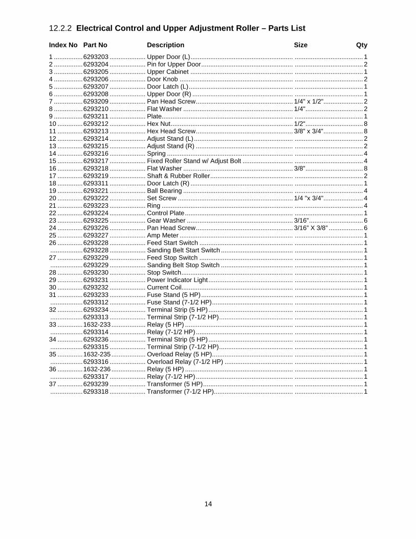
12.2.2 Electrical Control and Upper Adjustment Roller – Parts List
Index No Part No Description Size Qty 1 ................ 6293203 .................... Upper Door (L) ......................................................... ...................................... 1 2 ................ 6293204 .................... Pin for Upper Door ................................................... ...................................... 2 3 ................ 6293205 .................... Upper Cabinet ......................................................... ...................................... 1 4 ................ 6293206 .................... Door Knob ............................................................... ...................................... 2 5 ................ 6293207 .................... Door Latch (L) .......................................................... ...................................... 1 6 ................ 6293208 .................... Upper Door (R) ........................................................ ...................................... 1 7 ................ 6293209 .................... Pan Head Screw ...................................................... 1/4" x 1/2"...................... 2 8 ................ 6293210 .................... Flat Washer ............................................................. 1/4" ................................ 2 9 ................ 6293211 .................... Plate......................................................................... ...................................... 1 10 .............. 6293212 .................... Hex Nut .................................................................... 1/2" ................................ 8 11 .............. 6293213 .................... Hex Head Screw ...................................................... 3/8” x 3/4" ...................... 8 12 .............. 6293214 .................... Adjust Stand (L) ....................................................... ...................................... 2 13 .............. 6293215 .................... Adjust Stand (R) ...................................................... ...................................... 2 14 .............. 6293216 .................... Spring ...................................................................... ...................................... 4 15 .............. 6293217 .................... Fixed Roller Stand w/ Adjust Bolt ............................ ...................................... 4 16 .............. 6293218 .................... Flat Washer ............................................................. 3/8” ................................ 8 17 .............. 6293219 .................... Shaft & Rubber Roller .............................................. ...................................... 2 18 .............. 6293311 .................... Door Latch (R) ......................................................... ...................................... 1 19 .............. 6293221 .................... Ball Bearing ............................................................. ...................................... 4 20 .............. 6293222 .................... Set Screw ................................................................ 1/4 "x 3/4"...................... 4 21 .............. 6293223 .................... Ring ......................................................................... ...................................... 4 22 .............. 6293224 .................... Control Plate ............................................................ ...................................... 1 23 .............. 6293225 .................... Gear Washer ........................................................... 3/16” .............................. 6 24 .............. 6293226 .................... Pan Head Screw ...................................................... 3/16” X 3/8” ................... 6 25 .............. 6293227 .................... Amp Meter ............................................................... ...................................... 1 26 .............. 6293228 .................... Feed Start Switch .................................................... ...................................... 1 .................. 6293228 .................... Sanding Belt Start Switch ........................................ ...................................... 1 27 .............. 6293229 .................... Feed Stop Switch .................................................... ...................................... 1 .................. 6293229 .................... Sanding Belt Stop Switch ........................................ ...................................... 1 28 .............. 6293230 .................... Stop Switch .............................................................. ...................................... 1 29 .............. 6293231 .................... Power Indicator Light ............................................... ...................................... 1 30 .............. 6293232 .................... Current Coil.............................................................. ...................................... 1 31 .............. 6293233 .................... Fuse Stand (5 HP) ................................................... ...................................... 1 .................. 6293312 .................... Fuse Stand (7-1/2 HP) ............................................. ...................................... 1 32 .............. 6293234 .................... Terminal Strip (5 HP) ............................................... ...................................... 1 .................. 6293313 .................... Terminal Strip (7-1/2 HP) ......................................... ...................................... 1 33 .............. 1632-233 ................... Relay (5 HP) ............................................................ ...................................... 1 .................. 6293314 .................... Relay (7-1/2 HP) ...................................................... ...................................... 1 34 .............. 6293236 .................... Terminal Strip (5 HP) ............................................... ...................................... 1 .................. 6293315 .................... Terminal Strip (7-1/2 HP) ......................................... ...................................... 1 35 .............. 1632-235 ................... Overload Relay (5 HP)............................................. ...................................... 1 .................. 6293316 .................... Overload Relay (7-1/2 HP) ...................................... ...................................... 1 36 .............. 1632-236 ................... Relay (5 HP) ............................................................ ...................................... 1 .................. 6293317 .................... Relay (7-1/2 HP) ...................................................... ...................................... 1 37 .............. 6293239 .................... Transformer (5 HP) .................................................. ...................................... 1 .................. 6293318 .................... Transformer (7-1/2 HP)............................................ ...................................... 1
15
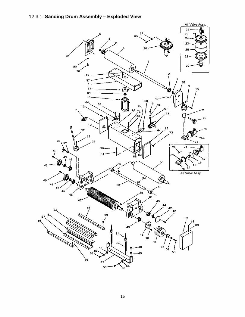
12.3.1 Sanding Drum Assembly – Exploded View

16
12.3.2 Sanding Drum Assembly – Parts List
Index No Part No Description Size Qty 1 ................ 6293240 .................... Ring ......................................................................... ...................................... 2 2 ................ 6293241 .................... Ball Bearing ............................................................. ...................................... 2 3 ................ 6293242 .................... Shaft ........................................................................ ...................................... 1 4 ................ 6293243 .................... Upper Roller............................................................. ...................................... 1 5 ................ 6293244 .................... Upper Roller Base (L) .............................................. ...................................... 1 6 ................ 6293245 .................... Column .................................................................... ...................................... 1 7 ................ 6293246 .................... Switch Valve ............................................................ ...................................... 1 8 ................ 6293247 .................... Eccentric Shaft Base ............................................... ...................................... 1 9 ................ 6293248 .................... Eccentric Shaft......................................................... ...................................... 1 10 .............. 6293249 .................... Hex Head Screw ...................................................... 5/16” x 1/2" .................... 2 11 .............. 6293250 .................... Air Cylinder Assembly.............................................. ...................................... 1 12 .............. 6293251 .................... Cover (L) .................................................................. ...................................... 1 13 .............. 6293252 .................... Air Oscillator Cylinder .............................................. ...................................... 1 .................. 6293496 .................... Air Valve Assembly (Items 14 thru 17, 74, 75, 79 & 86) ................................. 1 14 .............. 6293253 .................... Front Cover .............................................................. ...................................... 1 15 .............. 6293254 .................... Oscillator Shaft ........................................................ ...................................... 1 16 .............. 6293255 .................... Membrane................................................................ ...................................... 1 17 .............. 6293256 .................... Rear Cover .............................................................. ...................................... 1 18 .............. 6293257 .................... Column .................................................................... ...................................... 1 19 .............. 6293258 .................... Cover (R) ................................................................. ...................................... 1 20 .............. 6293259 .................... Air Sensor ................................................................ ...................................... 1 .................. 6293497 .................... Air Valve Assembly (Items 21 thru 26 & 79) ............ ...................................... 1 21 .............. 6293260 .................... Lower Cover ............................................................ ...................................... 1 22 .............. 6293261 .................... Air Sensor Substance .............................................. ...................................... 1 23 .............. 6293262 .................... Piston ....................................................................... ...................................... 1 24 .............. 6293263 .................... Upper Cover ............................................................ ...................................... 1 25 .............. 6293264 .................... Plastic Joint Assembly ............................................. ...................................... 1 26 .............. 6293265 .................... Membrane................................................................ ...................................... 1 27 .............. 6293266 .................... Handle Assembly ..................................................... ...................................... 1 28 .............. 6293267 .................... Set Screw ................................................................ 1/4" x 1/4"...................... 1 29 .............. 6293268 .................... Handle Hub .............................................................. ...................................... 1 30 .............. 6293269 .................... Hex Head Screw ...................................................... 3/8” x 1-1/4” .................. 4 31 .............. 6293270 .................... Adjust Bolt................................................................ 3/8” x 1-1/4” .................. 2 32 .............. 6293271 .................... Spring ...................................................................... ...................................... 2 33 .............. 6293272 .................... Shaft ........................................................................ ...................................... 1 34 .............. 6293273 .................... Key........................................................................... 5 x 5 x 30mm ................ 2 35 .............. 6293274 .................... Key........................................................................... 8 x 8 x 4 mm ................. 1 36 .............. 6293275 .................... Lock Handle ............................................................. ...................................... 1 37 .............. 6293276 .................... Knob ........................................................................ ...................................... 1 38 .............. 6293277 .................... Hex Head Screw ...................................................... 3/8” x 1-1/2” .................. 2 39 .............. 6293278 .................... Pan Head Screw ...................................................... 5/32” x 3/8” .................... 6 40 .............. 6293279 .................... Hex Socket Cap Screw ............................................ 1/4" x 1/2".................... 12 41 .............. 6293280 .................... Bearing Cover .......................................................... ...................................... 2 42 .............. 6293281 .................... Bearing Cover (L) .................................................... ...................................... 1 .................. 6293282 .................... Bearing Cover (R) .................................................... ...................................... 1 43 .............. 6293283 .................... Lock Nut (counter-clockwise)................................... ...................................... 2 44 .............. 6293284 .................... Lock Nut (clockwise) ................................................ ...................................... 1 45 .............. 6293285 .................... Ball Bearing ............................................................. ...................................... 4 46 .............. 6293286 .................... Round Bearing Frame ............................................. ...................................... 1 47 .............. 6293287 .................... Main Rubber Roller .................................................. ...................................... 1 48 .............. 6293288 .................... Hex Head Screw ...................................................... 5/16” x 1-3/4” ................ 2 49 .............. 6293289 .................... Hex Nut .................................................................... 5/16” .............................. 2 50 .............. 6293290 .................... Back Steel Roller ..................................................... ...................................... 1 51 .............. 6293291 .................... Blanket ..................................................................... ...................................... 1 52 .............. 6293292 .................... Pad Slider ................................................................ ...................................... 1 53 .............. 6293293 .................... Hex Head Screw ...................................................... 3/8” x 1” ......................... 2 54 .............. 6293294 .................... Pad .......................................................................... ...................................... 1 55 .............. 6293218 .................... Flat Washer ............................................................. 3/8” ................................ 2 56 .............. 6293295 .................... Pressing Bar ............................................................ ...................................... 2
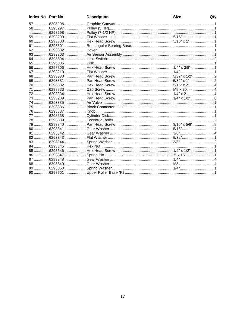
17
Index No Part No Description Size Qty 57 .............. 6293296 .................... Graphite Canvas ...................................................... ...................................... 1 58 .............. 6293297 .................... Pulley (5 HP)............................................................ ...................................... 1 .................. 6293298 .................... Pulley (7-1/2 HP) ..................................................... ...................................... 1 59 .............. 6293299 .................... Flat Washer ............................................................. 5/16” .............................. 1 60 .............. 6293300 .................... Hex Head Screw ...................................................... 5/16” x 1” ....................... 1 61 .............. 6293301 .................... Rectangular Bearing Base ....................................... ...................................... 1 62 .............. 6293302 .................... Cover ....................................................................... ...................................... 1 63 .............. 6293303 .................... Air Sensor Assembly ............................................... ...................................... 1 64 .............. 6293304 .................... Limit Switch.............................................................. ...................................... 2 65 .............. 6293305 .................... Disk .......................................................................... ...................................... 1 66 .............. 6293306 .................... Hex Head Screw ...................................................... 1/4" x 3/8” ...................... 1 67 .............. 6293210 .................... Flat Washer ............................................................. 1/4" ................................ 1 68 .............. 6293330 .................... Pan Head Screw ...................................................... 5/32” x 1/2" .................... 2 69 .............. 6293331 .................... Pan Head Screw ...................................................... 5/32” x 1” ....................... 2 70 .............. 6293332 .................... Hex Head Screw ...................................................... 5/16” x 2” ....................... 4 71 .............. 6293333 .................... Cap Screw ............................................................... M8 x 20 ......................... 4 72 .............. 6293334 .................... Hex Head Screw ...................................................... 1/4" x 2 .......................... 4 73 .............. 6293209 .................... Pan Head Screw ...................................................... 1/4" x 1/2"...................... 6 74 .............. 6293335 .................... Air Valve .................................................................. ...................................... 1 75 .............. 6293336 .................... Block Connector ...................................................... ...................................... 1 76 .............. 6293337 .................... Knob ........................................................................ ...................................... 1 77 .............. 6293338 .................... Cylinder Disk............................................................ ...................................... 1 78 .............. 6293339 .................... Eccentric Roller........................................................ ...................................... 2 79 .............. 6293340 .................... Pan Head Screw ...................................................... 3/16” x 5/8” .................... 8 80 .............. 6293341 .................... Gear Washer ........................................................... 5/16” .............................. 4 81 .............. 6293342 .................... Gear Washer ........................................................... 3/8” ................................ 4 82 .............. 6293343 .................... Flat Washer ............................................................. 5/32” .............................. 1 83 .............. 6293344 .................... Spring Washer ......................................................... 3/8” ................................ 2 84 .............. 6293345 .................... Hex Nut .................................................................... ...................................... 1 85 .............. 6293346 .................... Hex Head Screw ...................................................... 1/4" x 1/2"...................... 1 86 .............. 6293347 .................... Spring Pin ................................................................ 3” x 16” .......................... 1 87 .............. 6293348 .................... Gear Washer ........................................................... 1/4" ................................ 4 88 .............. 6293349 .................... Gear Washer ........................................................... M8 ................................. 4 89 .............. 6293350 .................... Spring Washer ......................................................... 1/4" ................................ 1 90 .............. 6293501 .................... Upper Roller Base (R) ............................................. ...................................... 1

18
12.4.1 Base and Table Adjustment Assembly – Parts List

19
12.4.2 Base and Table Adjustment Assembly – Parts List
Index No Part No Description Size Qty 1 ................ 6293415 .................... Door ......................................................................... ...................................... 1 2 ................ 6293416 .................... Crosspiece ............................................................... ...................................... 1 3 ................ 6293417 .................... Door Knob ............................................................... ...................................... 1 4 ................ 6293418 .................... Cover ....................................................................... ...................................... 1 5 ................ 6293419 .................... Hex Head Screw ...................................................... 1/4" x 1” ......................... 4 6 ................ 6293420 .................... Base......................................................................... ...................................... 1 7 ................ 6293421 .................... Cover ....................................................................... ...................................... 1 8 ................ 6293422 .................... Hex Head Screw ...................................................... 3/16” x 3/8” .................... 4 9 ................ 6293423 .................... Flat Washer ............................................................. 3/16” .............................. 4 10 .............. 1632-410 ................... Motor (s/n 05061632360 and higher) ......................... 5 HP, 1 PH .................... 1 .................. 6293425 .................... Motor........................................................................ 7-1/2 HP, 3 PH .............. 1 11 .............. 6293293 .................... Hex Head Screw ...................................................... 3/8” x 1” ......................... 4 12 .............. 6293426 .................... Lock Washer ............................................................ 3/8” ................................ 4 13 .............. 6293427 .................... Brake Base .............................................................. ...................................... 1 14 .............. 6293428 .................... Brake Pole ............................................................... ...................................... 1 15 .............. 6293429 .................... Brake Spring ............................................................ ...................................... 2 16 .............. 6293430 .................... Brake ....................................................................... ...................................... 2 17 .............. 6293431 .................... Bolt........................................................................... 5/1”6 x 1-1/2” ................ 1 18 .............. 6293432 .................... Bolt........................................................................... 1/2" ................................ 1 19 .............. 6293433 .................... Socket Head Screw ................................................. 5/16” x 1/2" .................... 6 20 .............. 6293434 .................... Bolt........................................................................... 3/8” x 1-1/2” .................. 1 21 .............. 1632-421 ................... Pulley (5 HP)............................................................ ...................................... 1 .................. 6293436 .................... Pulley (7-1/2 HP) ..................................................... ...................................... 1 22 .............. 6293210 .................... Flat Washer ............................................................. 1/4" ................................ 1 23 .............. 6293437 .................... Hex Head Screw ...................................................... 1/4" x 1” ......................... 1 24 .............. 1632-424 ................... Motor Plate (5 HP) (s/n 05061632360 and higher) .... ...................................... 1 .................. 6293439 .................... Motor Plate (7-1/2 HP) ............................................. ...................................... 1 25 .............. 6293212 .................... Hex Nut .................................................................... 1/2" ................................ 1 26 .............. 6293440 .................... Base......................................................................... ...................................... 1 27 .............. 6293441 .................... Set Screw ................................................................ 5/16” x 1” ....................... 4 28 .............. 6293442 .................... Hex Socket Cap Screw ............................................ 5/16” x 1-1/2” ................ 4 29 .............. 6293299 .................... Flat Washer ............................................................. 5/16” .............................. 1 30 .............. 1632-430 ................... Belt (s/n 05061632360 and higher) ............................ A-84 .............................. 2 31 .............. 6293444 .................... Flat Head Screw ...................................................... 1/4" x 1/2"...................... 2 32 .............. 6293445 .................... Key........................................................................... 19 x 3/8 x 270 ............... 1 33 .............. 6293446 .................... Base Lifting Pipe ...................................................... ...................................... 1 34 .............. 6293447 .................... Cap Screw ............................................................... 3/4" ................................ 1 35 .............. 6293249 .................... Hex Head Screw ...................................................... 5/16” X 1/2" ................... 4 36 .............. 6293341 .................... Gear Washer ........................................................... 5/16” .............................. 4 37 .............. 6293448 .................... Spring Pin ................................................................ 5 x 25mm ...................... 1 38 .............. 6293449 .................... Lock Handle ............................................................. ...................................... 1 39 .............. 6293450 .................... Hex Nut .................................................................... 1/4" ................................ 2 40 .............. 6293451 .................... Bolt........................................................................... 1/4" x 290mm ................ 1 41 .............. 6293452 .................... Lock Washer ............................................................ 1/4" ................................ 1 42 .............. 6293453 .................... Gear ......................................................................... ...................................... 1 43 .............. 6293454 .................... Ring ......................................................................... ...................................... 1 44 .............. 6293455 .................... Ball Bearing ............................................................. ...................................... 2 45 .............. 6293456 .................... Bolt........................................................................... 3/8” X 4” ........................ 2 46 .............. 6293457 .................... Hex Nut .................................................................... 3/8” ................................ 6 47 .............. 6293218 .................... Flat Washer ............................................................. 3/8” ................................ 4 48 .............. 6293458 .................... Hex Head Screw ...................................................... 3/8” X 1-3/4” .................. 4 49 .............. 6293459 .................... Ring ......................................................................... ...................................... 1 50 .............. 6293460 .................... Gear Box.................................................................. ...................................... 1 51 .............. 6293461 .................... Ball Bearing ............................................................. ...................................... 2 52 .............. 6293462 .................... Worm Gear .............................................................. ...................................... 1 53 .............. 6293218 .................... Flat Washer ............................................................. 3/8” ................................ 4 54 .............. 6293463 .................... Shaft ........................................................................ ...................................... 1 55 .............. 6293267 .................... Set Screw ................................................................ 1/4" x 1/4"...................... 2 56 .............. 6293464 .................... Set Screw ................................................................ 1/4" x 1” ......................... 1
20
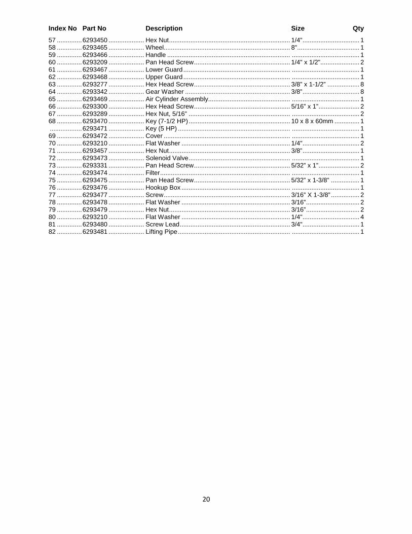
Index No Part No Description Size Qty 57 .............. 6293450 .................... Hex Nut .................................................................... 1/4" ................................ 1 58 .............. 6293465 .................... Wheel....................................................................... 8" ................................... 1 59 .............. 6293466 .................... Handle ..................................................................... ...................................... 1 60 .............. 6293209 .................... Pan Head Screw ...................................................... 1/4" x 1/2"...................... 2 61 .............. 6293467 .................... Lower Guard ............................................................ ...................................... 1 62 .............. 6293468 .................... Upper Guard ............................................................ ...................................... 1 63 .............. 6293277 .................... Hex Head Screw ...................................................... 3/8” x 1-1/2” .................. 8 64 .............. 6293342 .................... Gear Washer ........................................................... 3/8” ................................ 8 65 .............. 6293469 .................... Air Cylinder Assembly.............................................. ...................................... 1 66 .............. 6293300 .................... Hex Head Screw ...................................................... 5/16” x 1” ....................... 2 67 .............. 6293289 .................... Hex Nut, 5/16" ......................................................... ...................................... 2 68 .............. 6293470 .................... Key (7-1/2 HP) ......................................................... 10 x 8 x 60mm .............. 1 .................. 6293471 .................... Key (5 HP) ............................................................... ...................................... 1 69 .............. 6293472 .................... Cover ....................................................................... ...................................... 1 70 .............. 6293210 .................... Flat Washer ............................................................. 1/4" ................................ 2 71 .............. 6293457 .................... Hex Nut .................................................................... 3/8” ................................ 1 72 .............. 6293473 .................... Solenoid Valve ......................................................... ...................................... 1 73 .............. 6293331 .................... Pan Head Screw ...................................................... 5/32” x 1” ....................... 2 74 .............. 6293474 .................... Filter ......................................................................... ...................................... 1 75 .............. 6293475 .................... Pan Head Screw ...................................................... 5/32” x 1-3/8” ................ 1 76 .............. 6293476 .................... Hookup Box ............................................................. ...................................... 1 77 .............. 6293477 .................... Screw ....................................................................... 3/16” X 1-3/8” ................ 2 78 .............. 6293478 .................... Flat Washer ............................................................. 3/16” .............................. 2 79 .............. 6293479 .................... Hex Nut .................................................................... 3/16” .............................. 2 80 .............. 6293210 .................... Flat Washer ............................................................. 1/4" ................................ 4 81 .............. 6293480 .................... Screw Lead .............................................................. 3/4" ................................ 1 82 .............. 6293481 .................... Lifting Pipe ............................................................... ...................................... 1
21
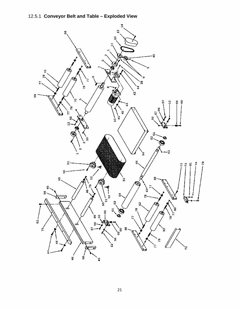
12.5.1 Conveyor Belt and Table – Exploded View

22
12.5.2 Reduction Motor – Exploded View
23
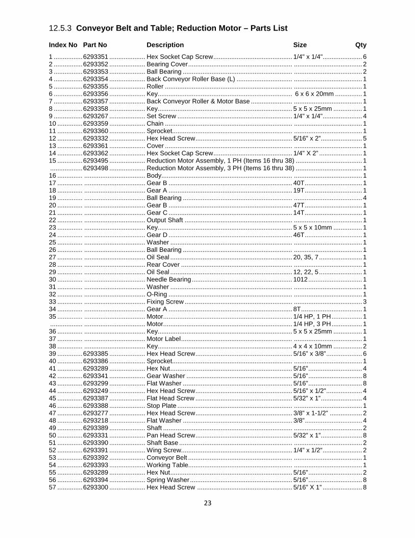
12.5.3 Conveyor Belt and Table; Reduction Motor – Parts List
Index No Part No Description Size Qty 1 ................ 6293351 .................... Hex Socket Cap Screw ............................................ 1/4" x 1/4"...................... 6 2 ................ 6293352 .................... Bearing Cover .......................................................... ...................................... 2 3 ................ 6293353 .................... Ball Bearing ............................................................. ...................................... 2 4 ................ 6293354 .................... Back Conveyor Roller Base (L) ............................... ...................................... 1 5 ................ 6293355 .................... Roller ....................................................................... ...................................... 1 6 ................ 6293356 .................... Key........................................................................... 6 x 6 x 20mm ............... 1 7 ................ 6293357 .................... Back Conveyor Roller & Motor Base ....................... ...................................... 1 8 ................ 6293358 .................... Key........................................................................... 5 x 5 x 25mm ................ 1 9 ................ 6293267 .................... Set Screw ................................................................ 1/4" x 1/4"...................... 4 10 .............. 6293359 .................... Chain ....................................................................... ...................................... 1 11 .............. 6293360 .................... Sprocket................................................................... ...................................... 1 12 .............. 6293332 .................... Hex Head Screw ...................................................... 5/16” x 2” ....................... 5 13 .............. 6293361 .................... Cover ....................................................................... ...................................... 1 14 .............. 6293362 .................... Hex Socket Cap Screw ............................................ 1/4" X 2” ........................ 1 15 .............. 6293495 .................... Reduction Motor Assembly, 1 PH (Items 16 thru 38) ..................................... 1 .................. 6293498 .................... Reduction Motor Assembly, 3 PH (Items 16 thru 38) ..................................... 1 16 .............. .................................. Body......................................................................... ...................................... 1 17 .............. .................................. Gear B ..................................................................... 40T ................................ 1 18 .............. .................................. Gear A ..................................................................... 19T ................................ 1 19 .............. .................................. Ball Bearing ............................................................. ...................................... 4 20 .............. .................................. Gear B ..................................................................... 47T ................................ 1 21 .............. .................................. Gear C ..................................................................... 14T ................................ 1 22 .............. .................................. Output Shaft ............................................................ ...................................... 1 23 .............. .................................. Key........................................................................... 5 x 5 x 10mm ................ 1 24 .............. .................................. Gear D ..................................................................... 46T ................................ 1 25 .............. .................................. Washer .................................................................... ...................................... 1 26 .............. .................................. Ball Bearing ............................................................. ...................................... 1 27 .............. .................................. Oil Seal .................................................................... 20, 35, 7 ........................ 1 28 .............. .................................. Rear Cover .............................................................. ...................................... 1 29 .............. .................................. Oil Seal .................................................................... 12, 22, 5 ........................ 1 30 .............. .................................. Needle Bearing ........................................................ 1012 .............................. 1 31 .............. .................................. Washer .................................................................... ...................................... 1 32 .............. .................................. O-Ring ..................................................................... ...................................... 1 33 .............. .................................. Fixing Screw ............................................................ ...................................... 3 34 .............. .................................. Gear A ..................................................................... 8T .................................. 1 35 .............. .................................. Motor........................................................................ 1/4 HP, 1 PH ................. 1 .................. .................................. Motor........................................................................ 1/4 HP, 3 PH ................. 1 36 .............. .................................. Key........................................................................... 5 x 5 x 25mm ................ 1 37 .............. .................................. Motor Label .............................................................. ...................................... 1 38 .............. .................................. Key........................................................................... 4 x 4 x 10mm ................ 2 39 .............. 6293385 .................... Hex Head Screw ...................................................... 5/16” x 3/8” .................... 6 40 .............. 6293386 .................... Sprocket................................................................... ...................................... 1 41 .............. 6293289 .................... Hex Nut .................................................................... 5/16” .............................. 4 42 .............. 6293341 .................... Gear Washer ........................................................... 5/16” .............................. 8 43 .............. 6293299 .................... Flat Washer ............................................................. 5/16” .............................. 8 44 .............. 6293249 .................... Hex Head Screw ...................................................... 5/16” x 1/2" .................... 4 45 .............. 6293387 .................... Flat Head Screw ...................................................... 5/32” x 1” ....................... 4 46 .............. 6293388 .................... Stop Plate ................................................................ ...................................... 1 47 .............. 6293277 .................... Hex Head Screw ...................................................... 3/8” x 1-1/2” .................. 2 48 .............. 6293218 .................... Flat Washer ............................................................. 3/8” ................................ 4 49 .............. 6293389 .................... Shaft ........................................................................ ...................................... 2 50 .............. 6293331 .................... Pan Head Screw ...................................................... 5/32” x 1” ....................... 8 51 .............. 6293390 .................... Shaft Base ............................................................... ...................................... 2 52 .............. 6293391 .................... Wing Screw.............................................................. 1/4” x 1/2" ...................... 2 53 .............. 6293392 .................... Conveyor Belt .......................................................... ...................................... 1 54 .............. 6293393 .................... Working Table.......................................................... ...................................... 1 55 .............. 6293289 .................... Hex Nut .................................................................... 5/16” .............................. 2 56 .............. 6293394 .................... Spring Washer ......................................................... 5/16” .............................. 8 57 .............. 6293300 .................... Hex Head Screw ..................................................... 5/16” X 1” ...................... 8
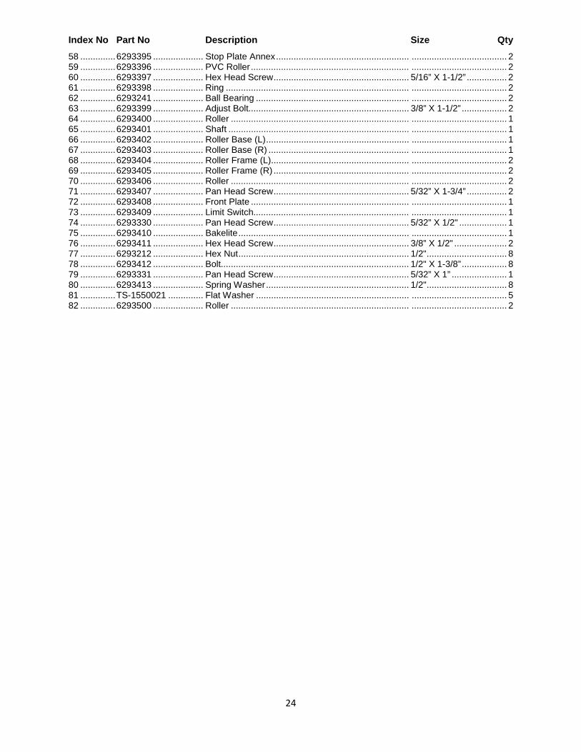
24
Index No Part No Description Size Qty 58 .............. 6293395 .................... Stop Plate Annex ..................................................... ...................................... 2 59 .............. 6293396 .................... PVC Roller ............................................................... ...................................... 2 60 .............. 6293397 .................... Hex Head Screw ...................................................... 5/16” X 1-1/2” ................ 2 61 .............. 6293398 .................... Ring ......................................................................... ...................................... 2 62 .............. 6293241 .................... Ball Bearing ............................................................. ...................................... 2 63 .............. 6293399 .................... Adjust Bolt................................................................ 3/8” X 1-1/2” .................. 2 64 .............. 6293400 .................... Roller ....................................................................... ...................................... 1 65 .............. 6293401 .................... Shaft ........................................................................ ...................................... 1 66 .............. 6293402 .................... Roller Base (L) ......................................................... ...................................... 1 67 .............. 6293403 .................... Roller Base (R) ........................................................ ...................................... 1 68 .............. 6293404 .................... Roller Frame (L)....................................................... ...................................... 2 69 .............. 6293405 .................... Roller Frame (R) ...................................................... ...................................... 2 70 .............. 6293406 .................... Roller ....................................................................... ...................................... 2 71 .............. 6293407 .................... Pan Head Screw ...................................................... 5/32” X 1-3/4” ................ 2 72 .............. 6293408 .................... Front Plate ............................................................... ...................................... 1 73 .............. 6293409 .................... Limit Switch.............................................................. ...................................... 1 74 .............. 6293330 .................... Pan Head Screw ...................................................... 5/32” X 1/2" ................... 1 75 .............. 6293410 .................... Bakelite .................................................................... ...................................... 1 76 .............. 6293411 .................... Hex Head Screw ...................................................... 3/8” X 1/2" ..................... 2 77 .............. 6293212 .................... Hex Nut .................................................................... 1/2" ................................ 8 78 .............. 6293412 .................... Bolt........................................................................... 1/2" X 1-3/8” .................. 8 79 .............. 6293331 .................... Pan Head Screw ...................................................... 5/32” X 1” ...................... 1 80 .............. 6293413 .................... Spring Washer ......................................................... 1/2" ................................ 8 81 .............. TS-1550021 .............. Flat Washer ............................................................. ...................................... 5 82 .............. 6293500 .................... Roller ....................................................................... ...................................... 2
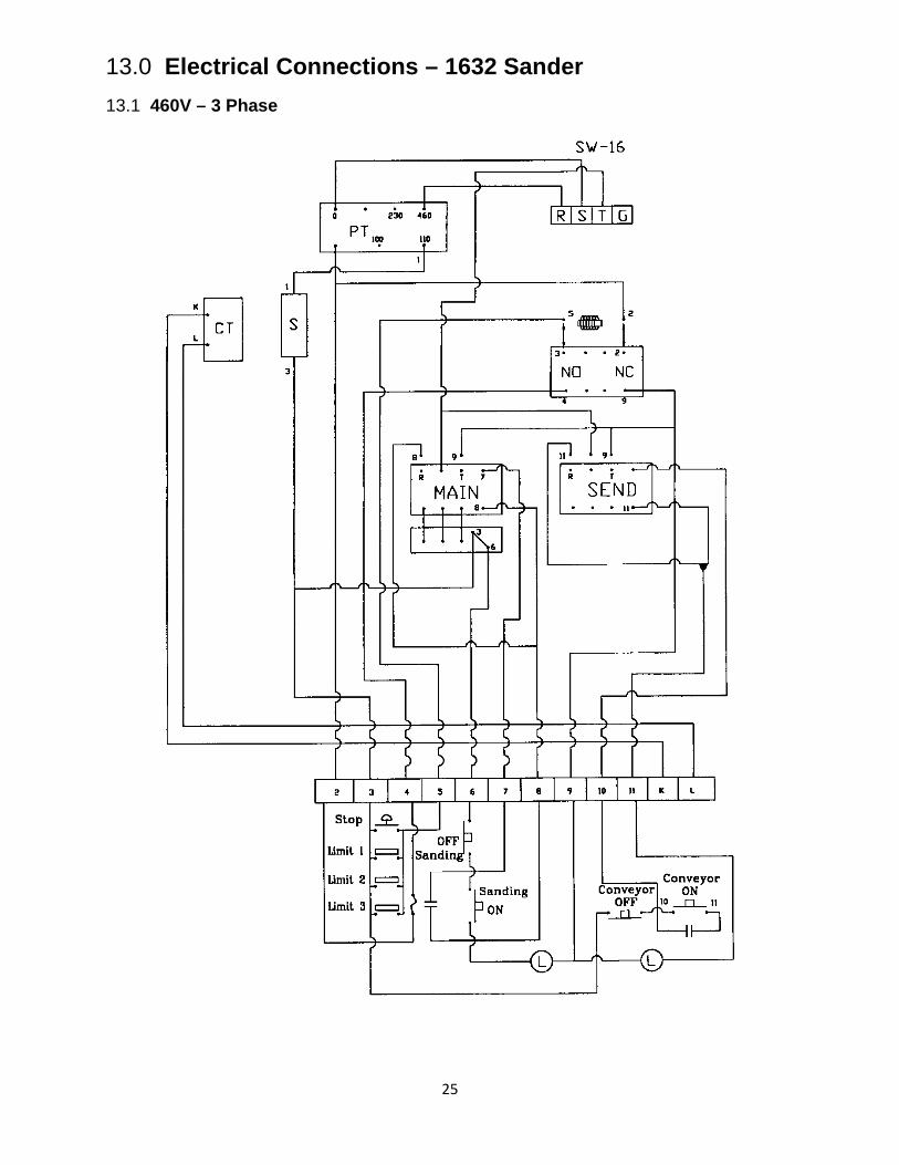
25
13.0 Electrical Connections – 1632 Sander 13.1 460V – 3 Phase
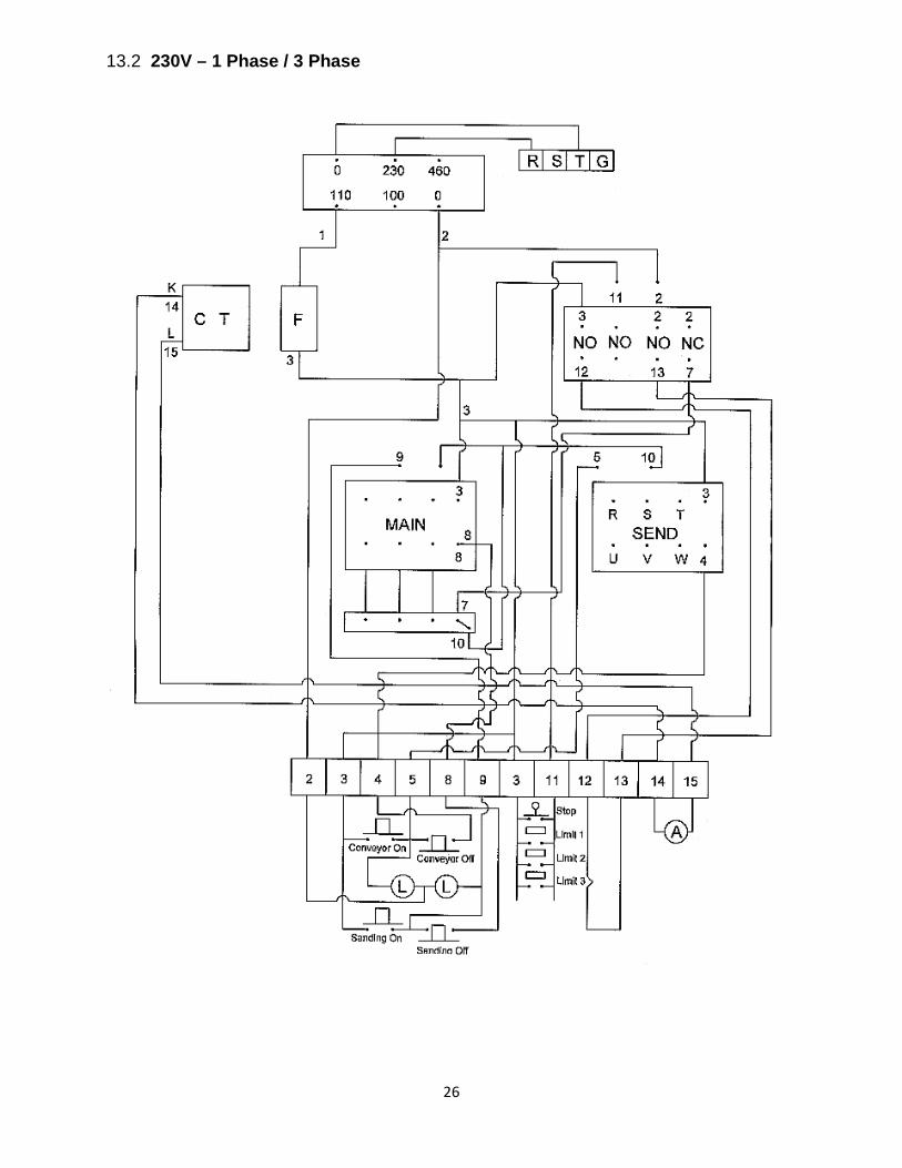
26
13.2 230V – 1 Phase / 3 Phase

27
This page intentionally left blank.

28
This page intentionally left blank.
427 New Sanford Road LaVergne, Tennessee 37086
Phone: 800-274-6848 www.powermatic.com