Embed Size (px)
Citation preview
1
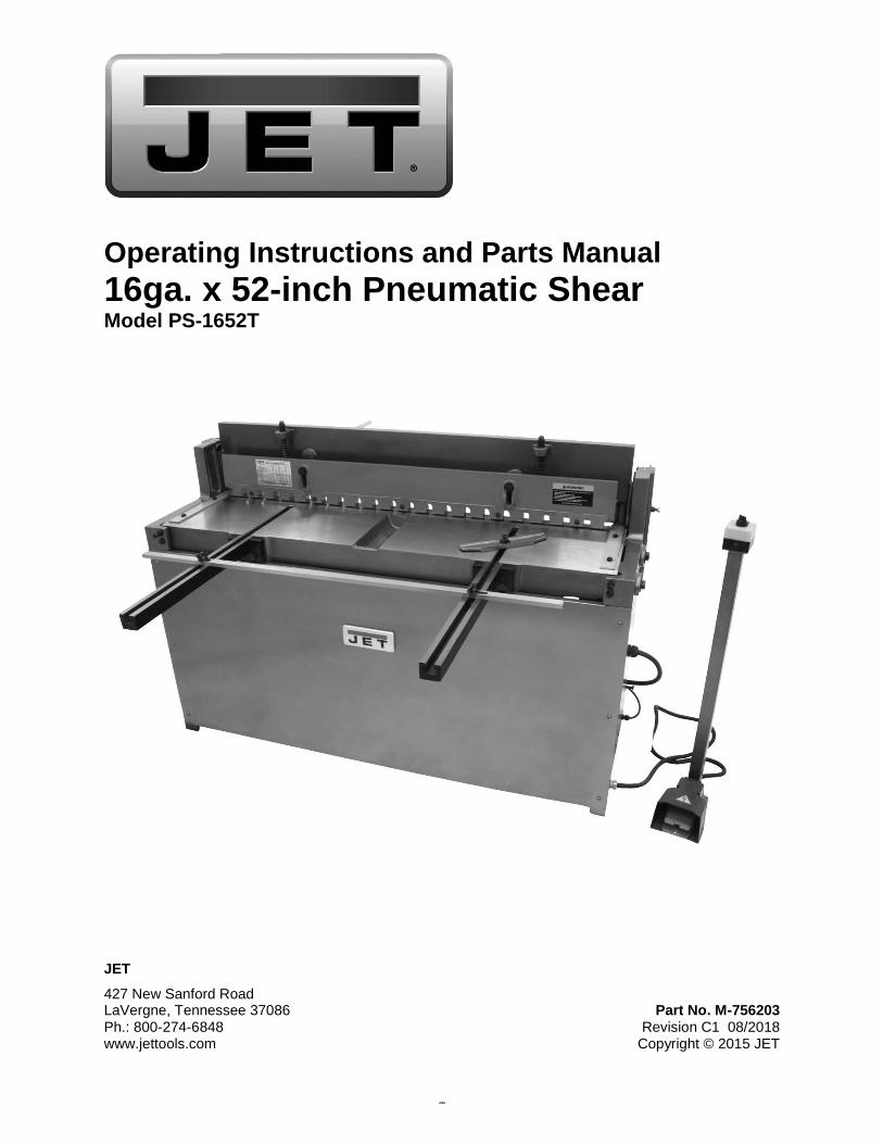
Operating Instructions and Parts Manual 16ga. x 52-inch Pneumatic Shear Model PS-1652T
JET
427 New Sanford Road LaVergne, Tennessee 37086 Part No. M-756203 Ph.: 800-274-6848 Revision C1 08/2018 www.jettools.com Copyright © 2015 JET
2
1.0 IMPORTANT SAFETY INSTRUCTIONS
READ ALL INSTRUCTIONS BEFORE USING THIS MACHINE.
WARNING – To reduce risk of injury: 1. Read and understand the entire owner’s
manual before attempting assembly or operation.
2. Read and understand the warnings posted on the machine and in this manual. Failure to comply with all of these warnings may cause serious injury. Replace warning labels if they become obscured or removed.
3. This pneumatic shear is designed and intended for use by properly trained and experienced personnel only. If you are not familiar with the proper and safe operation of a shear, do not use until proper training and knowledge have been obtained.
4. Do not use this machine for other than its intended use. If used for other purposes, JET disclaims any real or implied warranty and holds itself harmless from any injury that may result from that use.
5. Always wear ANSI approved safety glasses/face shields while using this shear. Everyday eyeglasses only have impact resistant lenses; they are not safety glasses.
6. Do not wear loose clothing, gloves, neckties, rings, bracelets, or other jewelry which may get caught in moving parts. Wear protective hair covering to contain long hair. Non-slip footwear or anti-skid floor strips are recommended.
7. Do not operate this machine while tired or under the influence of drugs, alcohol or any medication.
8. Do not exceed the rated capacity of this shear; use hand tools for small or narrow parts. Do not attempt to shear hardened materials.
9. Sheet metal stock has sharp edges. To prevent cuts, use leather work gloves when handling.
10. Keep hands and fingers clear of the area in front and rear of the shear.
11. Do not place your hands between material being sheared and the shear table.
12. Keep safety guards in place at all times when the machine is in use. If removed for maintenance purposes, use extreme caution and replace the guards immediately after maintenance is complete.
13. Check damaged parts. Before further use of the machine, a guard or other part that is damaged should be carefully checked to determine that it will operate properly and perform its intended function. Check for alignment of moving parts, binding of moving parts, breakage of parts, mounting and any other conditions that may affect its operation. A guard or other part that is damaged should be properly repaired or replaced.
14. Provide for adequate space surrounding work area and non-glare, overhead lighting.
15. Keep the floor around the machine clean and free of scrap material, oil and grease.
16. Keep visitors a safe distance from the work area. Keep children away.
17. Make your workshop child proof with padlocks, master switches or by removing starter keys.
18. Give your work undivided attention. Looking around, carrying on a conversation and “horse-play” are careless acts that can result in serious injury.
19. Maintain a balanced stance at all times so that you do not fall or lean against moving parts. Do not overreach or use excessive force to perform any machine operation.
20. Use the right tool at the correct speed and feed rate. Do not force a tool or attachment to do a job for which it was not designed. The right tool will do the job better and more safely.
21. Use recommended accessories; improper accessories may be hazardous.
22. Maintain tools with care. Keep tools sharp and clean for the best and safest performance. Follow instructions for lubricating and changing accessories.
23. Do not stand on the machine. Serious injury could occur if the machine tips over.
24. Unplug or lock out power to the machine when not in use.
WARNING: This product can expose you to chemicals including lead which is known to the State of California to cause cancer and birth defects or other reproductive harm. For more information go to http://www.p65warnings.ca. gov.
3
Familiarize yourself with the following safety notices used in this manual.
This means that if precautions are not heeded, it may result in minor injury and/or possible machine damage.
This means that if precautions are not heeded, it may result in serious or even fatal injury.
2.0 About this manual This manual is provided by JET covering the safe operation and maintenance procedures for a JET Model PS-1652T Pneumatic Shear. This manual contains instructions on installation, safety precautions, general operating procedures, maintenance instructions and parts breakdown. Your machine has been designed and constructed to provide consistent, long-term operation if used in accordance with the instructions set forth in this document.
If there are questions or comments, please contact your local supplier or JET. JET can also be reached at our web site: www.jettools.com.
Retain this manual for future reference. If the machine transfers ownership, the manual should accompany it.
WARNING: Some dust, fumes and gases created by power sanding, sawing, grinding, drilling, welding and other construction activities contain chemicals known to the State of California to cause cancer and birth defects or other reproductive harm. Some examples of these chemicals are: • lead from lead based paint • crystalline silica from bricks, cement and
other masonry products • arsenic and chromium from chemically
treated lumber Your risk of exposure varies, depending on how often you do this type of work. To reduce your exposure to these chemicals, work in a well-ventilated area and work with approved safety equipment, such as dust masks that are specifically designed to filter out microscopic particles. For more information go to http://www.p65warnings.ca.gov/ and http:// www.p65warnings.ca.gov/wood.
4
3.0 Warranty and Service JET® warrants every product it sells against manufacturers’ defects. If one of our tools needs service or repair, please contact Technical Service by calling 1-800-274-6846, 8AM to 5PM CST, Monday through Friday.
Warranty Period The general warranty lasts for the time period specified in the literature included with your product or on the official JET branded website.
• JET products carry a limited warranty which varies in duration based upon the product. (See chart below) • Accessories carry a limited warranty of one year from the date of receipt. • Consumable items are defined as expendable parts or accessories expected to become inoperable within a
reasonable amount of use and are covered by a 90 day limited warranty against manufacturer’s defects.
Who is Covered This warranty covers only the initial purchaser of the product from the date of delivery.
What is Covered This warranty covers any defects in workmanship or materials subject to the limitations stated below. This warranty does not cover failures due directly or indirectly to misuse, abuse, negligence or accidents, normal wear-and-tear, improper repair, alterations or lack of maintenance. JET woodworking machinery is designed to be used with Wood. Use of these machines in the processing of metal, plastics, or other materials outside recommended guidelines may void the warranty. The exceptions are acrylics and other natural items that are made specifically for wood turning.
Warranty Limitations Woodworking products with a Five Year Warranty that are used for commercial or industrial purposes default to a Two Year Warranty. Please contact Technical Service at 1-800-274-6846 for further clarification.
How to Get Technical Support Please contact Technical Service by calling 1-800-274-6846. Please note that you will be asked to provide proof of initial purchase when calling. If a product requires further inspection, the Technical Service representative will explain and assist with any additional action needed. JET has Authorized Service Centers located throughout the United States. For the name of an Authorized Service Center in your area call 1-800-274-6846 or use the Service Center Locator on the JET website.
More Information JET is constantly adding new products. For complete, up-to-date product information, check with your local distributor or visit the JET website.
How State Law Applies This warranty gives you specific legal rights, subject to applicable state law.
Limitations on This Warranty JET LIMITS ALL IMPLIED WARRANTIES TO THE PERIOD OF THE LIMITED WARRANTY FOR EACH PRODUCT. EXCEPT AS STATED HEREIN, ANY IMPLIED WARRANTIES OF MERCHANTABILITY AND FITNESS FOR A PARTICULAR PURPOSE ARE EXCLUDED. SOME STATES DO NOT ALLOW LIMITATIONS ON HOW LONG AN IMPLIED WARRANTY LASTS, SO THE ABOVE LIMITATION MAY NOT APPLY TO YOU. JET SHALL IN NO EVENT BE LIABLE FOR DEATH, INJURIES TO PERSONS OR PROPERTY, OR FOR INCIDENTAL, CONTINGENT, SPECIAL, OR CONSEQUENTIAL DAMAGES ARISING FROM THE USE OF OUR PRODUCTS. SOME STATES DO NOT ALLOW THE EXCLUSION OR LIMITATION OF INCIDENTAL OR CONSEQUENTIAL DAMAGES, SO THE ABOVE LIMITATION OR EXCLUSION MAY NOT APPLY TO YOU. JET sells through distributors only. The specifications listed in JET printed materials and on official JET website are given as general information and are not binding. JET reserves the right to effect at any time, without prior notice, those alterations to parts, fittings, and accessory equipment which they may deem necessary for any reason whatsoever. JET® branded products are not sold in Canada by JPW Industries, Inc.
Product Listing with Warranty Period 90 Days – Parts; Consumable items 1 Year – Motors; Machine Accessories 2 Year – Metalworking Machinery; Electric Hoists, Electric Hoist Accessories; Woodworking Machinery used for industrial or commercial purposes 5 Year – Woodworking Machinery Limited Lifetime – JET Parallel clamps; VOLT Series Electric Hoists; Manual Hoists; Manual Hoist Accessories; Shop Tools; Warehouse & Dock products; Hand Tools; Air Tools
NOTE: JET is a division of JPW Industries, Inc. References in this document to JET also apply to JPW Industries, Inc., or any of its successors in interest to the JET brand.
5
4.0 Table of Contents Section Page 1.0 IMPORTANT SAFETY INSTRUCTIONS ....................................................................................................... 2 2.0 About this manual .......................................................................................................................................... 3 3.0 Warranty and Service ..................................................................................................................................... 4 4.0 Table of Contents ........................................................................................................................................... 5 5.0 General Features and Terminology ............................................................................................................... 6 6.0 Specifications ................................................................................................................................................. 7 7.0 Set-Up and Assembly .................................................................................................................................... 8
7.1 Hole center dimensions .............................................................................................................................. 8 7.2 Unpacking .................................................................................................................................................. 8 7.3 Stop assemblies ......................................................................................................................................... 8 7.4 Electrical connections ................................................................................................................................. 9
8.0 Adjustments ................................................................................................................................................. 10 8.1 Table and blades ...................................................................................................................................... 10 8.2 Air regulator .............................................................................................................................................. 10 8.3 Rear stop micro adjust ............................................................................................................................. 10 8.4 Hold-down tension .................................................................................................................................... 10 8.5 Gibs .......................................................................................................................................................... 10
9.0 Maintenance ................................................................................................................................................. 11 10.0 Troubleshooting ......................................................................................................................................... 11 11.0 Replacement Parts ..................................................................................................................................... 11
11.1.1 PS-1652T Assembly – Exploded View ................................................................................................ 12 11.1.2 PS-1652T Assembly – Parts List ......................................................................................................... 13
12.0 Electrical connections ................................................................................................................................ 16
6
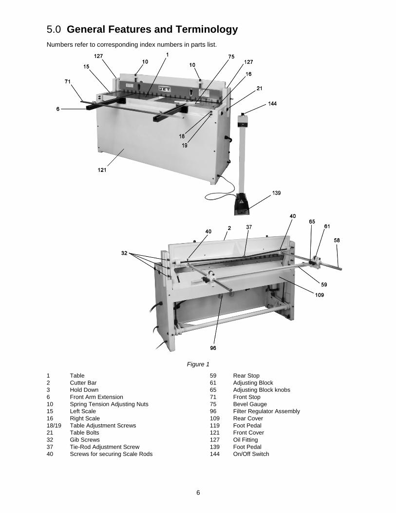
5.0 General Features and Terminology Numbers refer to corresponding index numbers in parts list.
Figure 1
1 Table 2 Cutter Bar 3 Hold Down 6 Front Arm Extension 10 Spring Tension Adjusting Nuts 15 Left Scale 16 Right Scale 18/19 Table Adjustment Screws 21 Table Bolts 32 Gib Screws 37 Tie-Rod Adjustment Screw 40 Screws for securing Scale Rods
59 Rear Stop 61 Adjusting Block 65 Adjusting Block knobs 71 Front Stop 75 Bevel Gauge 96 Filter Regulator Assembly 109 Rear Cover 119 Foot Pedal 121 Front Cover 127 Oil Fitting 139 Foot Pedal 144 On/Off Switch
7
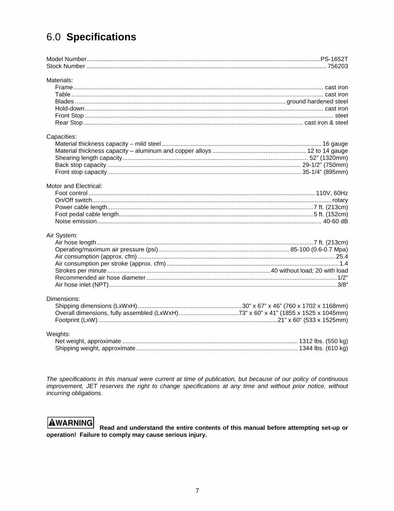
6.0 Specifications Model Number ......................................................................................................................................... PS-1652T Stock Number ............................................................................................................................................. 756203 Materials:
Frame ................................................................................................................................................... cast iron Table .................................................................................................................................................... cast iron Blades ............................................................................................................................ ground hardened steel Hold-down ............................................................................................................................................ cast iron Front Stop .................................................................................................................................................. steel Rear Stop ................................................................................................................................. cast iron & steel
Capacities:
Material thickness capacity – mild steel .............................................................................................. 16 gauge Material thickness capacity – aluminum and copper alloys ....................................................... 12 to 14 gauge Shearing length capacity ............................................................................................................. 52” (1320mm) Back stop capacity .................................................................................................................. 29-1/2” (750mm) Front stop capacity .................................................................................................................. 35-1/4” (895mm)
Motor and Electrical:
Foot control ..................................................................................................................................... 110V, 60Hz On/Off switch............................................................................................................................................. rotary Power cable length......................................................................................................................... 7 ft. (213cm) Foot pedal cable length .................................................................................................................. 5 ft. (152cm) Noise emission .................................................................................................................................... 40-60 dB
Air System:
Air hose length ............................................................................................................................... 7 ft. (213cm) Operating/maximum air pressure (psi) ............................................................................. 85-100 (0.6-0.7 Mpa) Air consumption (approx. cfm) .................................................................................................................... 25.4 Air consumption per stroke (approx. cfm) ..................................................................................................... 1.4 Strokes per minute ................................................................................................ 40 without load; 20 with load Recommended air hose diameter ................................................................................................................ 1/2" Air hose inlet (NPT) ...................................................................................................................................... 3/8”
Dimensions:
Shipping dimensions (LxWxH) ............................................................. 30” x 67” x 46” (760 x 1702 x 1168mm) Overall dimensions, fully assembled (LxWxH) ................................... 73” x 60” x 41” (1855 x 1525 x 1045mm) Footprint (LxW) ......................................................................................................... 21” x 60” (533 x 1525mm)
Weights:
Net weight, approximate ....................................................................................................... 1312 lbs. (550 kg) Shipping weight, approximate ............................................................................................... 1344 lbs. (610 kg)
The specifications in this manual were current at time of publication, but because of our policy of continuous improvement, JET reserves the right to change specifications at any time and without prior notice, without incurring obligations.
Read and understand the entire contents of this manual before attempting set-up or
operation! Failure to comply may cause serious injury.
8
7.0 Set-Up and Assembly
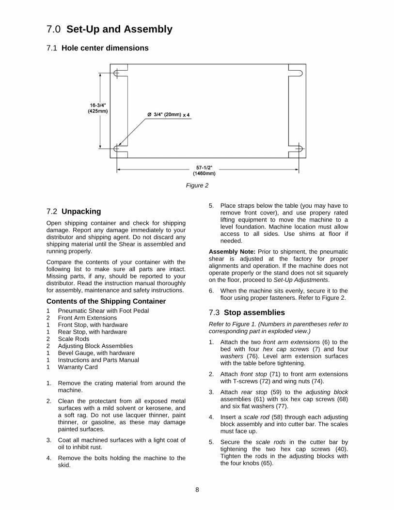
7.1 Hole center dimensions
Figure 2
7.2 Unpacking Open shipping container and check for shipping damage. Report any damage immediately to your distributor and shipping agent. Do not discard any shipping material until the Shear is assembled and running properly.
Compare the contents of your container with the following list to make sure all parts are intact. Missing parts, if any, should be reported to your distributor. Read the instruction manual thoroughly for assembly, maintenance and safety instructions.
Contents of the Shipping Container 1 Pneumatic Shear with Foot Pedal 2 Front Arm Extensions 1 Front Stop, with hardware 1 Rear Stop, with hardware 2 Scale Rods 2 Adjusting Block Assemblies 1 Bevel Gauge, with hardware 1 Instructions and Parts Manual 1 Warranty Card 1. Remove the crating material from around the
machine.
2. Clean the protectant from all exposed metal surfaces with a mild solvent or kerosene, and a soft rag. Do not use lacquer thinner, paint thinner, or gasoline, as these may damage painted surfaces.
3. Coat all machined surfaces with a light coat of oil to inhibit rust.
4. Remove the bolts holding the machine to the skid.
5. Place straps below the table (you may have to remove front cover), and use propery rated lifting equipment to move the machine to a level foundation. Machine location must allow access to all sides. Use shims at floor if needed.
Assembly Note: Prior to shipment, the pneumatic shear is adjusted at the factory for proper alignments and operation. If the machine does not operate properly or the stand does not sit squarely on the floor, proceed to Set-Up Adjustments.
6. When the machine sits evenly, secure it to the floor using proper fasteners. Refer to Figure 2.
7.3 Stop assemblies Refer to Figure 1. (Numbers in parentheses refer to corresponding part in exploded view.)
1. Attach the two front arm extensions (6) to the bed with four hex cap screws (7) and four washers (76). Level arm extension surfaces with the table before tightening.
2. Attach front stop (71) to front arm extensions with T-screws (72) and wing nuts (74).
3. Attach rear stop (59) to the adjusting block assemblies (61) with six hex cap screws (68) and six flat washers (77).
4. Insert a scale rod (58) through each adjusting block assembly and into cutter bar. The scales must face up.
5. Secure the scale rods in the cutter bar by tightening the two hex cap screws (40). Tighten the rods in the adjusting blocks with the four knobs (65).
9
7.4 Electrical connections
Electrical connections must be made by a qualified electrician in compliance with all relevant codes. This machine must be properly grounded to help prevent electrical shock and possible fatal injury.
7.4.1 Grounding instructions
This machine must be grounded. In the event of a malfunction or breakdown, grounding provides a path of least resistance for electric current to reduce the risk of electric shock.
The Pneumatic Shear is equipped with a 15 amp cord and plug set, with a grounding prong. The plug must be plugged into a matching outlet that is properly installed and grounded in accordance with all local codes and ordinances. Do not modify the plug provided – if it will not fit the outlet, have the proper outlet installed by a qualified electrician.
Improper connection of the equipment-grounding conductor can result in a risk of electric shock. The conductor with insulation having an outer surface that is green with or without yellow stripes, is the equipment-grounding conductor. If repair or replacement of the electric cord or plug is necessary, do not connect the equipment-grounding conductor to a live terminal.
Check with a qualified electrician or service personnel if the grounding instructions are not completely understood, or if in doubt as to whether the tool is properly grounded. Repair or replace a damaged or worn cord immediately.
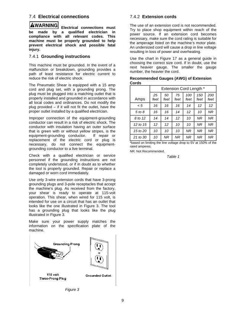
Use only 3-wire extension cords that have 3-prong grounding plugs and 3-pole receptacles that accept the machine’s plug. As received from the factory, your shear is ready to operate at 115-volt operation. This shear, when wired for 115 volt, is intended for use on a circuit that has an outlet that looks like the one illustrated in Figure 3. The tool has a grounding plug that looks like the plug illustrated in Figure 3.
Make sure your power supply matches the information on the specification plate of the machine.
Figure 3
7.4.2 Extension cords
The use of an extension cord is not recommended. Try to place shop equipment within reach of the power source. If an extension cord becomes necessary, make sure the cord rating is suitable for the amperage listed on the machine’s motor plate. An undersized cord will cause a drop in line voltage resulting in loss of power and overheating.
Use the chart in Figure 17 as a general guide in choosing the correct size cord. If in doubt, use the next heavier gauge. The smaller the gauge number, the heavier the cord.
Recommended Gauges (AWG) of Extension Cords
Amps
Extension Cord Length * 25 feet
50 feet
75 feet
100 feet
150 feet
200 feet
< 5 16 16 16 14 12 12
5 to 8 16 16 14 12 10 NR
8 to 12 14 14 12 10 NR NR
12 to 15 12 12 10 10 NR NR
15 to 20 10 10 10 NR NR NR
21 to 30 10 NR NR NR NR NR *based on limiting the line voltage drop to 5V at 150% of the rated amperes. NR: Not Recommended.
Table 1
10
8.0 Adjustments
8.1 Table and blades 1. If the table requires adjustment, loosen four
bolts (21); do not remove. Loosen nuts on the adjusting screws (18,19). The bed must rest squarely on the right and left hand side panels at all four corners while screws are loose. Shim legs at floor if necessary. Tighten hardware.
2. Use set screw (18) and hex cap screw (19), to adjust the lower blade toward or away from the upper blade. The distance between the upper and lower blades should be 0.002-0.005”. Do not let the blades overlap.
3. Connect machine to electrical supply, and adjust the air pressure until the gauge reads approximately 90 psi.
4. Place a heavy sheet of paper (~0.005”/0.13mm) in the cutting position, along the entire length of the bed.
5. Turn switch to ON and press the foot pedal.
6. If the shear does not cut the paper, move the lower blade toward the upper blade.
7. If the shear cuts the paper on the ends, but not the center, turn the tie-rod adjusting screw (37), clockwise until the paper is cut the entire length.
8. If the shear cuts the paper in the center, but not the ends, turn the tie-rod adjusting screw (37) counter-clockwise until the paper is cut the entire length.
9. Make sure the scales (15,16) on top of the table are square to the blade, and also show the correct distance from the blade.
10. Make test cuts to verify that the scales are correct.
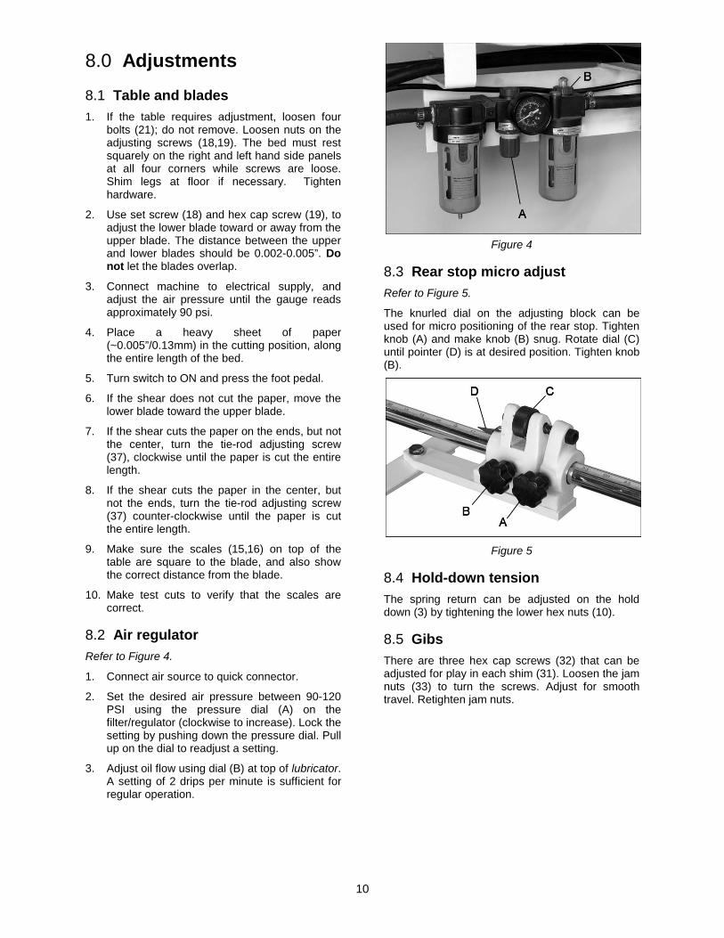
8.2 Air regulator Refer to Figure 4.
1. Connect air source to quick connector.
2. Set the desired air pressure between 90-120 PSI using the pressure dial (A) on the filter/regulator (clockwise to increase). Lock the setting by pushing down the pressure dial. Pull up on the dial to readjust a setting.
3. Adjust oil flow using dial (B) at top of lubricator. A setting of 2 drips per minute is sufficient for regular operation.
Figure 4
8.3 Rear stop micro adjust Refer to Figure 5.
The knurled dial on the adjusting block can be used for micro positioning of the rear stop. Tighten knob (A) and make knob (B) snug. Rotate dial (C) until pointer (D) is at desired position. Tighten knob (B).
Figure 5
8.4 Hold-down tension The spring return can be adjusted on the hold down (3) by tightening the lower hex nuts (10).
8.5 Gibs There are three hex cap screws (32) that can be adjusted for play in each shim (31). Loosen the jam nuts (33) to turn the screws. Adjust for smooth travel. Retighten jam nuts.
11
9.0 Maintenance
Use care when working with or around the knives.
The 2-way upper knife can be removed and flipped 180°, for a new edge before having to be sharpened.
Periodically insert oil through the two oil fittings (127) atop the side panels. Use ISO VG32 or equivalent.
Wipe the knives lightly with oil.
Lubricate all pivot points on the machine daily.
Empty the condensation cups on the air regulator as needed.
10.0 Troubleshooting Trouble Probable Cause Remedy
Blades will not cut material.
Incorrect gap between blades. Increase gap for thicker gauge metals.
Material exceeds machine capacity. Stay within capacity.
Blades are dull. Replace or sharpen blades.
Unsatisfactory cuts.
Blades dull. Replace or sharpen blades.
Incorrect gap between blades. Correct gap.
Loose gibs. Remove backlash from gibs.
Cuts not square.
Inadequate hold-down pressure. Adjust pressure of hold-down.
Blade gap unequal. Adjust gap equally across length of blade.
Uneven guide contact. Place work against guide consistently.
Blade is bowed. Adjust blade bow at the tie-rod.
11.0 Replacement Parts Replacement parts are listed on the following pages. To order parts or reach our service department, call 1-800-274-6848 Monday through Friday, 8:00 a.m. to 5:00 p.m. CST. Having the Model Number and Serial Number of your machine available when you call will allow us to serve you quickly and accurately.
Some parts are shown for reference only, and may not be available individually.
Non-proprietary parts, such as fasteners, can usually be found at local hardware stores, or may be ordered from JET.
12
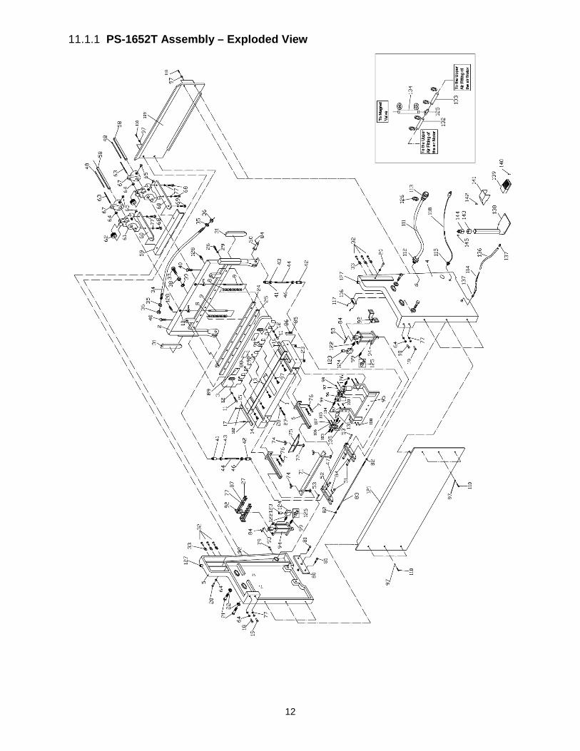
11.1.1 PS-1652T Assembly – Exploded View
13
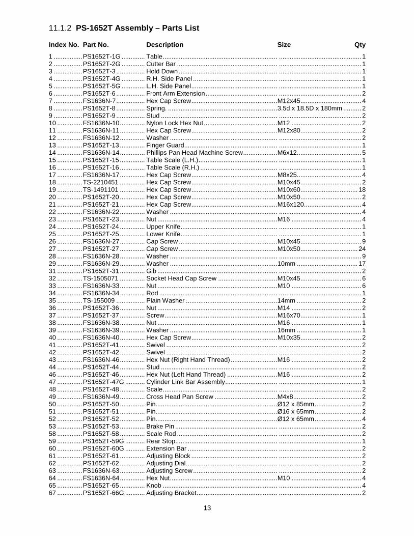
11.1.2 PS-1652T Assembly – Parts List
Index No. Part No. Description Size Qty 1 ................ PS1652T-1G ............. Table ................................................................ .............................................. 1 2 ................ PS1652T-2G ............. Cutter Bar ........................................................ .............................................. 1 3 ................ PS1652T-3 ................ Hold Down ....................................................... .............................................. 1 4 ................ PS1652T-4G ............. R.H. Side Panel ............................................... .............................................. 1 5 ................ PS1652T-5G ............. L.H. Side Panel ................................................ .............................................. 1 6 ................ PS1652T-6 ................ Front Arm Extension ........................................ .............................................. 2 7 ................ FS1636N-7 ................ Hex Cap Screw ................................................ M12x45 .................................. 4 8 ................ PS1652T-8 ................ Spring. ............................................................. 3.5d x 18.5D x 180mm .......... 2 9 ................ PS1652T-9 ................ Stud ................................................................. .............................................. 2 10 .............. FS1636N-10 .............. Nylon Lock Hex Nut ......................................... M12 ....................................... 2 11 .............. FS1636N-11 .............. Hex Cap Screw ................................................ M12x80 .................................. 2 12 .............. FS1636N-12 .............. Washer ............................................................ .............................................. 2 13 .............. PS1652T-13 .............. Finger Guard.................................................... .............................................. 1 14 .............. FS1636N-14 .............. Phillips Pan Head Machine Screw ................... M6x12 .................................... 5 15 .............. PS1652T-15 .............. Table Scale (L.H.) ............................................ .............................................. 1 16 .............. PS1652T-16 .............. Table Scale (R.H.) ........................................... .............................................. 1 17 .............. FS1636N-17 .............. Hex Cap Screw ................................................ M8x25 .................................... 4 18 .............. TS-2210451 .............. Hex Cap Screw ................................................ M10x45 .................................. 2 19 .............. TS-1491101 .............. Hex Cap Screw ................................................ M10x60 ................................ 18 20 .............. PS1652T-20 .............. Hex Cap Screw ................................................ M10x50 .................................. 2 21 .............. PS1652T-21 .............. Hex Cap Screw ................................................ M16x120 ................................ 4 22 .............. FS1636N-22 .............. Washer ............................................................ .............................................. 4 23 .............. PS1652T-23 .............. Nut ................................................................... M16 ....................................... 4 24 .............. PS1652T-24 .............. Upper Knife ...................................................... .............................................. 1 25 .............. PS1652T-25 .............. Lower Knife ...................................................... .............................................. 1 26 .............. FS1636N-27 .............. Cap Screw ....................................................... M10x45 .................................. 9 27 .............. PS1652T-27 .............. Cap Screw ....................................................... M10x50 ................................ 24 28 .............. FS1636N-28 .............. Washer ............................................................ .............................................. 9 29 .............. FS1636N-29 .............. Washer ............................................................ 10mm .................................. 17 31 .............. PS1652T-31 .............. Gib ................................................................... .............................................. 2 32 .............. TS-1505071 .............. Socket Head Cap Screw ................................. M10x45 .................................. 6 33 .............. FS1636N-33 .............. Nut ................................................................... M10 ....................................... 6 34 .............. FS1636N-34 .............. Rod .................................................................. .............................................. 1 35 .............. TS-155009 ................ Plain Washer ................................................... 14mm .................................... 2 36 .............. PS1652T-36 .............. Nut ................................................................... M14 ....................................... 2 37 .............. PS1652T-37 .............. Screw ............................................................... M16x70 .................................. 1 38 .............. FS1636N-38 .............. Nut ................................................................... M16 ....................................... 1 39 .............. FS1636N-39 .............. Washer ............................................................ 16mm .................................... 1 40 .............. FS1636N-40 .............. Hex Cap Screw ................................................ M10x35 .................................. 2 41 .............. PS1652T-41 .............. Swivel .............................................................. .............................................. 2 42 .............. PS1652T-42 .............. Swivel .............................................................. .............................................. 2 43 .............. FS1636N-46 .............. Hex Nut (Right Hand Thread) .......................... M16 ....................................... 2 44 .............. PS1652T-44 .............. Stud ................................................................. .............................................. 2 46 .............. PS1652T-46 .............. Hex Nut (Left Hand Thread) ............................ M16 ....................................... 2 47 .............. PS1652T-47G ........... Cylinder Link Bar Assembly ............................. .............................................. 1 48 .............. PS1652T-48 .............. Scale ................................................................ .............................................. 2 49 .............. FS1636N-49 .............. Cross Head Pan Screw ................................... M4x8 ...................................... 2 50 .............. PS1652T-50 .............. Pin.................................................................... Ø12 x 85mm .......................... 2 51 .............. PS1652T-51 .............. Pin.................................................................... Ø16 x 65mm .......................... 2 52 .............. PS1652T-52 .............. Pin.................................................................... Ø12 x 65mm .......................... 4 53 .............. PS1652T-53 .............. Brake Pin ......................................................... .............................................. 2 58 .............. PS1652T-58 .............. Scale Rod ........................................................ .............................................. 2 59 .............. PS1652T-59G ........... Rear Stop......................................................... .............................................. 1 60 .............. PS1652T-60G ........... Extension Bar .................................................. .............................................. 2 61 .............. PS1652T-61 .............. Adjusting Block ................................................ .............................................. 2 62 .............. PS1652T-62 .............. Adjusting Dial ................................................... .............................................. 2 63 .............. FS1636N-63 .............. Adjusting Screw ............................................... .............................................. 2 64 .............. FS1636N-64 .............. Hex Nut ............................................................ M10 ....................................... 4 65 .............. PS1652T-65 .............. Knob ................................................................ .............................................. 4 67 .............. PS1652T-66G ........... Adjusting Bracket ............................................. .............................................. 2
14
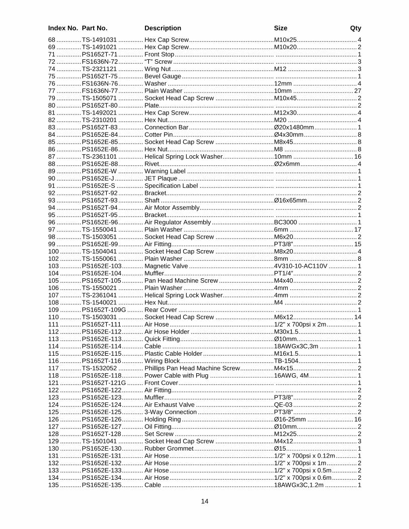
Index No. Part No. Description Size Qty 68 .............. TS-1491031 .............. Hex Cap Screw ................................................ M10x25 .................................. 4 69 .............. TS-1491021 .............. Hex Cap Screw ................................................ M10x20 .................................. 2 71 .............. PS1652T-71 .............. Front Stop ........................................................ .............................................. 1 72 .............. FS1636N-72 .............. “T” Screw ......................................................... .............................................. 3 74 .............. TS-2321121 .............. Wing Nut .......................................................... M12 ....................................... 3 75 .............. PS1652T-75 .............. Bevel Gauge .................................................... .............................................. 1 76 .............. FS1636N-76 .............. Washer ............................................................ 12mm .................................... 4 77 .............. FS1636N-77 .............. Plain Washer ................................................... 10mm .................................. 27 79 .............. TS-1505071 .............. Socket Head Cap Screw ................................. M10x45 .................................. 2 80 .............. PS1652T-80 .............. Plate................................................................. .............................................. 2 81 .............. TS-1492021 .............. Hex Cap Screw ................................................ M12x30 .................................. 4 82 .............. TS-2310201 .............. Hex Nut ............................................................ M20 ....................................... 4 83 .............. PS1652T-83 .............. Connection Bar ................................................ Ø20x1480mm ........................ 1 84 .............. PS1652E-84 .............. Cotter Pin ......................................................... Ø4x30mm .............................. 8 85 .............. PS1652E-85 .............. Socket Head Cap Screw ................................. M8x45 .................................... 8 86 .............. PS1652E-86 .............. Hex Nut ............................................................ M8 ......................................... 8 87 .............. TS-2361101 .............. Helical Spring Lock Washer............................. 10mm .................................. 16 88 .............. PS1652E-88 .............. Rivet................................................................. Ø2x6mm ................................ 4 89 .............. PS1652E-W .............. Warning Label ................................................. .............................................. 1 90 .............. PS1652E-J ................ JET Plaque ...................................................... .............................................. 1 91 .............. PS1652E-S ............... Specification Label .......................................... .............................................. 1 92 .............. PS1652T-92 .............. Bracket............................................................. .............................................. 2 93 .............. PS1652T-93 .............. Shaft ................................................................ Ø16x65mm ............................ 2 94 .............. PS1652T-94 .............. Air Motor Assembly.......................................... .............................................. 2 95 .............. PS1652T-95 .............. Bracket............................................................. .............................................. 1 96 .............. PS1652E-96 .............. Air Regulator Assembly ................................... BC3000 ................................. 1 97 .............. TS-1550041 .............. Plain Washer ................................................... 6mm .................................... 17 98 .............. TS-1503051 .............. Socket Head Cap Screw ................................. M6x20 .................................... 2 99 .............. PS1652E-99 .............. Air Fitting.......................................................... PT3/8” .................................. 15 100 ............ TS-1504041 .............. Socket Head Cap Screw ................................. M8x20 .................................... 4 102 ............ TS-1550061 .............. Plain Washer ................................................... 8mm ...................................... 8 103 ............ PS1652E-103 ............ Magnetic Valve ................................................ 4V310-10-AC110V ................ 1 104 ............ PS1652E-104 ............ Muffler .............................................................. PT1/4” .................................... 2 105 ............ PS1652T-105 ............ Pan Head Machine Screw ............................... M4x40 .................................... 2 106 ............ TS-1550021 .............. Plain Washer ................................................... 4mm ...................................... 2 107 ............ TS-2361041 .............. Helical Spring Lock Washer............................. 4mm ...................................... 2 108 ............ TS-1540021 .............. Hex Nut ............................................................ M4 ......................................... 2 109 ............ PS1652T-109G ......... Rear Cover ...................................................... .............................................. 1 110 ............ TS-1503031 .............. Socket Head Cap Screw ................................. M6x12 .................................. 14 111 ............ PS1652T-111 ............ Air Hose ........................................................... 1/2" x 700psi x 2m ................. 1 112 ............ PS1652E-112 ............ Air Hose Holder ............................................... M30x1.5 ................................. 1 113 ............ PS1652E-113 ............ Quick Fitting ..................................................... Ø10mm .................................. 1 114 ............ PS1652E-114 ............ Cable ............................................................... 18AWGx3C,3m ..................... 1 115 ............ PS1652E-115 ............ Plastic Cable Holder ........................................ M16x1.5 ................................. 1 116 ............ PS1652T-116 ............ Wiring Block ..................................................... TB-1504 ................................. 1 117 ............ TS-1532052 .............. Phillips Pan Head Machine Screw ................... M4x15 .................................... 2 118 ............ PS1652E-118 ............ Power Cable with Plug .................................... 16AWG, 4M ........................... 1 121 ............ PS1652T-121G ......... Front Cover ...................................................... .............................................. 1 122 ............ PS1652E-122 ............ Air Fitting.......................................................... .............................................. 2 123 ............ PS1652E-123 ............ Muffler .............................................................. PT3/8” .................................... 2 124 ............ PS1652E-124 ............ Air Exhaust Valve ............................................ QE-03 .................................... 2 125 ............ PS1652E-125 ............ 3-Way Connection ........................................... PT3/8” .................................... 2 126 ............ PS1652E-126 ............ Holding Ring .................................................... Ø16-25mm .......................... 16 127 ............ PS1652E-127 ............ Oil Fitting.......................................................... Ø10mm .................................. 2 128 ............ PS1652T-128 ............ Set Screw ........................................................ M12x25 .................................. 2 129 ............ TS-1501041 .............. Socket Head Cap Screw ................................. M4x12 .................................... 3 130 ............ PS1652E-130 ............ Rubber Grommet ............................................. Ø15 ........................................ 1 131 ............ PS1652E-131 ............ Air Hose ........................................................... 1/2" x 700psi x 0.12m ............ 1 132 ............ PS1652E-132 ............ Air Hose ........................................................... 1/2" x 700psi x 1m ................. 2 133 ............ PS1652E-133 ............ Air Hose ........................................................... 1/2" x 700psi x 0.5m .............. 2 134 ............ PS1652E-134 ............ Air Hose ........................................................... 1/2" x 700psi x 0.6m .............. 2 135 ............ PS1652E-135 ............ Cable ............................................................... 18AWGx3C,1.2m .................. 1
15
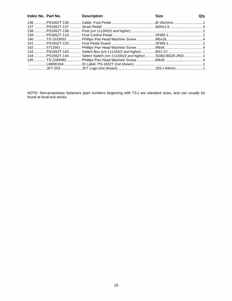
Index No. Part No. Description Size Qty 136 ............ PS1652T-136 ............ Cable, Foot Pedal ............................................ Ø 18x2mm ............................. 1 137 ............ PS1652T-137 ............ Strain Relief ..................................................... M20x1.5 ................................. 4 138 ............ PS1652T-138 ............ Post (s/n 11120022 and higher)......................... .............................................. 1 139 ............ PS1652T-119 ............ Foot Control Pedal ........................................... SFMS-1 ................................. 1 140 ............ TS-1533052 .............. Phillips Pan Head Machine Screw ................... M5x16 .................................... 4 141 ............ PS1652T-120 ............ Foot Pedal Guard ............................................ SFMS-1 ................................. 1 142 ............ 5712561 .................... Phillips Pan Head Machine Screw ................... M5x8 ...................................... 4 143 ............ PS1652T-143 ............ Switch Box (s/n 11120022 and higher) .............. BX1-22 .................................. 1 144 ............ PS1652T-144 ............ Select Switch (s/n 11120022 and higher) .......... SGB2-BD25 2NO .................. 1 145 ............ TS-2284082 .............. Phillips Pan Head Machine Screw ................... M4x8 ...................................... 4 .................. LM000164 ................. ID Label, PS-1652T (not shown) ..................... .............................................. 1 .................. JET-203 ..................... JET Logo (not shown) ..................................... 203 x 84mm ........................... 1
NOTE: Non-proprietary fasteners (part numbers beginning with TS-) are standard sizes, and can usually be found at local tool stores.
16
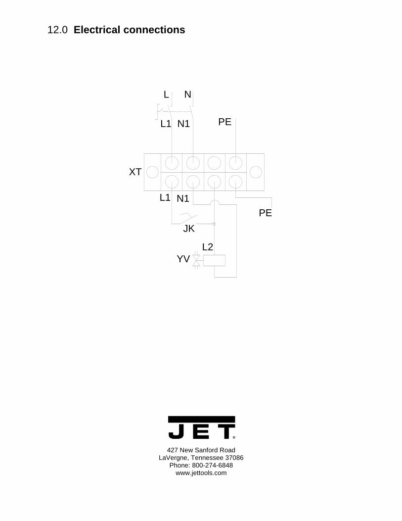
12.0 Electrical connections
427 New Sanford Road LaVergne, Tennessee 37086
Phone: 800-274-6848 www.jettools.com
NL
PE
N1L1
XT
JK
YVL2
L1 N1
PE
![MULTILAYER CERAMIC CHIP CAPACITORS€¦ · Type: C1005 [0402 inch], C1608 [0603 inch], C2012 [0805 inch], C3216 [1206 inch], C3225 [1210 inch], C4520 [1808 inch], C4532 [1812 inch],](https://img.pdfslide.net/doc/110x75/5f2a18c3f073e37da14b10b6/multilayer-ceramic-chip-capacitors-type-c1005-0402-inch-c1608-0603-inch-c2012.jpg)

![Commercial Grade, General (Up to 50V) C series€¦ · Type: C0402 [01005 inch] zC0603 [0201 inch] zC1005 [0402 inch] zC1608 [0603 inch] zC2012 [0805 inch] z C3216 [1206 inch] zC3225](https://img.pdfslide.net/doc/110x75/5f2a1ad70d2a3612680cda61/commercial-grade-general-up-to-50v-c-series-type-c0402-01005-inch-zc0603-0201.jpg)


![· PDF file3" Flange is Van Stone Style Size [inch] Part No. USD # holes bolt hole dia. [inch] bolt cir. dia. [inch] L [inch] M [inch] N [inch] R [inch]](https://img.pdfslide.net/doc/110x75/5a79cf987f8b9ad7608cd05d/flange-is-van-stone-style-size-inch-part-no-usd-holes-bolt-hole-dia-inch.jpg)