Embed Size (px)
Citation preview

WHM TOOL GROUP, Inc.427 New Sanford RoadLaVergne, Tennessee 30786 Part No. M-354221Ph.: 800-274-6848 Revision A 03/09www.wmhtoolgroup.com Copyright © 2009 WMH Tool Group, Inc.
Operating Instructions and Parts Manual20-Inch Variable Speed Drill PressModels: J-2221VS, J-2223VS, J-2232AC, J-2234AC
Model J-2221VS shown

Warranty and ServiceWMH Tool Group, Inc., warrants every product it sells. If one of our tools needs service or repair, one of our AuthorizedService Centers located throughout the United States can give you quick service. In most cases, any of these WMH ToolGroup Authorized Service Centers can authorize warranty repair, assist you in obtaining parts, or perform routine maintenanceand major repair on your JET® tools. For the name of an Authorized Service Center in your area call 1-800-274-6848.MORE INFORMATIONWMH Tool Group is consistently adding new products to the line. For complete, up-to-date product information, check withyour local WMH Tool Group distributor, or visit jettools.com.WARRANTYJET products carry a limited warranty which varies in duration based upon the product (MW stands for Metalworking, WWstands for Woodworking).
WHAT IS COVERED?This warranty covers any defects in workmanship or materials subject to the exceptions stated below. Cutting tools,abrasives and other consumables are excluded from warranty coverage.WHO IS COVERED?This warranty covers only the initial purchaser of the product.WHAT IS THE PERIOD OF COVERAGE?The general JET warranty lasts for the time period specified in the product literature of each product.WHAT IS NOT COVERED?Three Year, Five Year and Lifetime Warranties do not cover products used for industrial or educational purposes.Products with Three Year, Five Year or Lifetime Warranties that are used for industrial or education purposes revert to aOne Year Warranty. This warranty does not cover defects due directly or indirectly to misuse, abuse, negligence oraccidents, normal wear-and-tear, improper repair or alterations, or lack of maintenance.HOW TO GET SERVICEThe product or part must be returned for examination, postage prepaid, to a location designated by us. For the name ofthe location nearest you, please call 1-800-274-6848.You must provide proof of initial purchase date and an explanation of the complaint must accompany the merchandise.If our inspection discloses a defect, we will repair or replace the product, or refund the purchase price, at our option. Wewill return the repaired product or replacement at our expense unless it is determined by us that there is no defect, or thatthe defect resulted from causes not within the scope of our warranty in which case we will, at your direction, dispose ofor return the product. In the event you choose to have the product returned, you will be responsible for the shipping andhandling costs of the return.HOW STATE LAW APPLIESThis warranty gives you specific legal rights; you may also have other rights which vary from state to state.LIMITATIONS ON THIS WARRANTYWMH TOOL GROUP LIMITS ALL IMPLIED WARRANTIES TO THE PERIOD OF THE LIMITED WARRANTY FOR EACHPRODUCT. EXCEPT AS STATED HEREIN, ANY IMPLIED WARRANTIES OR MERCHANTABILITY AND FITNESS AREEXCLUDED. SOME STATES DO NOT ALLOW LIMITATIONS ON HOW LONG THE IMPLIED WARRANTY LASTS, SO THEABOVE LIMITATION MAY NOT APPLY TO YOU.WMH TOOL GROUP SHALL IN NO EVENT BE LIABLE FOR DEATH, INJURIES TO PERSONS OR PROPERTY, OR FORINCIDENTAL, CONTINGENT, SPECIAL, OR CONSEQUENTIAL DAMAGES ARISING FROM THE USE OF OUR PRODUCTS.SOME STATES DO NOT ALLOW THE EXCLUSION OR LIMITATION OF INCIDENTAL OR CONSEQUENTIAL DAMAGES,SO THE ABOVE LIMITATION OR EXCLUSION MAY NOT APPLY TO YOU.WMH Tool Group sells through distributors only. The specifications in WMH catalogs are given as general informationand are not binding. Members of WMH Tool Group reserve the right to effect at any time, without prior notice, thosealterations to parts, fittings, and accessory equipment which they may deem necessary for any reason whatsoever. JET®
branded products are not sold in Canada by WMH Tool Group.
YEARYEARDAYDAY WARRANTY
WARRANTY9090
WARRANTY
WARRANTY1
YEARYEAR WARRANTY
WARRANTY5
LIFETIMELIFETIME WARRANTY
WARRANTYLIFELIFE
YEARYEAR WARRANTY
WARRANTY2
YEARYEAR WARRANTY
WARRANTY3
Lathe AccessoriesMachine AccessoriesMobile BasesSafety EquipmentSpecialty ItemsVise Accessories
Air Tools- ContractorAir Tools-IndustrialAir Tools-Light IndustrialLubrication
Fastening ToolsMechanics Hand ToolsStriking ToolsVises (no -precision)Clamps
Palet TrucksRigging Equip.Service JacksStackersSurface GrindersTappingTrolleys-AirTrolleys-ElectricWeb SlingsWinches-Electric
Body Repair KitsBottle JacksCable PullersCold SawsHoists-AirHoists-ElectricMetal formingMill/DrillsMilling Machines
MW Precision Vises
MW BandsawsMW Drill PressesMW Finishing EquipmentMW Lathes
Beam ClampsChain Hoist- ManualLever HoistsPullers-JCH ModelsScissor Lift TablesScrew JacksTrolleys-GearedTrolleys-PlainWinches-ManualWW Air FiltrationWW BandsawsWW Buffers
WW Drill PressesWW Dust CollectorsWW Dust FiltersWW Dust FittingsWW JointersWW LathesWW PlanersWW Sanders
WW ShapersWW Tablesaws
WW Benchtop Tools
Warranty reverts to 1 Year Warranty if woodworking (WW) products listed above are used for industrial or educational purposes.

3
Table of ContentsCover Page....................................................................................................... 1General Specifications ...................................................................................... 4Operating Precautions ...................................................................................... 5Operation and Set-up ........................................................................................ 7Operating Controls ............................................................................................ 8Maintenance ................................................................................................... 10Machine Adjustments ...................................................................................... 11Wiring Diagram ............................................................................................... 13Troubleshooting............................................................................................... 15Accessories .................................................................................................... 16Replacement Parts.......................................................................................... 17

4
GeneralSpecificationsThe JET 20 Inch Variable Speed Drill pressesModels J-2221VS, J-2223VS, J-2232AC, andJ-2234AC are available in manual speed controlor inverter speed control configuration. Electricalpower options are single-phase, 115 and 220volts, or 3-phase, 440 volts.
Specifications Manual Speed Control Models Inverter Speed Control Models
Model J-2221VS J-2223VS J-2232AC J-2234ACStock Number ............................................. 354221 ................. 354223 ....................354214 ................. 354216Drilling Capacity
Cast Iron ............................................. 1-1/4 In. ................ 1-1/4 In. ...................1-1/2 In. ................ 1-1/2 In.Steel .................................................... 1 In. ....................... 1 In. ..........................1-3/8 In. ................. 1-3/8 In.
Spindle to Table (Max.) ................................. 32-3/8 In. ............... 32-3/8 In. ..................32-3/8 In. ............... 32-3/8 In.Spindle to Base (Max.) ................................ 44-1/2 In. ............... 44-1/2 In. ..................44-1/2 In. ............... 44-1/2 In.Spindle to Column (Max.) ............................ 10-7/16 In. ............. 10-7/16 In. ................10-7/16 In. ............. 10-7/16 In.Motor
Rating .................................................. 2 hp, 1-Phase ........ 2 hp, 3-Phase ..........2 hp, 3-Phase ....... 2 hp, 3-PhaseVoltage ................................................ 115/220 V .............. 220/440V ..................220V ...................... 440VPre-wired Voltage ................................ 115 V ..................... 220V ........................220V ...................... 440V
T-Slots (Table/Base)Number ............................................... 2 ............................ 2 ..............................2 ............................ 2Size ..................................................... 5/8 In. .................... 5/8 In. .......................5/8 In. .................... 5/8 In.
Column Diameter ........................................ 4-1/2 In. ................. 4-1/2 In. ....................4-1/2 In. ................. 4-1/2 In.Spindle
Travel .................................................. 6 In. ....................... 6 In. ..........................6 In. ....................... 6 In.Taper ................................................... MT-3 ...................... MT-3 .........................MT-3 ...................... MT-3RPM (Variable) .................................... 300-2000 ............... 300-2000 ..................65-2000 ................. 65-2000
QuillDiameter ............................................. 3 In. ....................... 3 In. ..........................3 In. ....................... 3 In.Travel .................................................. 6 in. ....................... 6 in. ..........................6 in. ....................... 6 in.
TableOverall ................................................. 22x18-3/4 In. .......... 22x18-3/4 In. ............22x18-3/4 In. .......... 22x18-3/4 In.Working Surface .................................. 18-1/8x14-3/4 ........ 18-1/8x14-3/4 ...........18-1/8x14-3/4 ........ 18-1/8x14-3/4Travel .................................................. 32-3/8 In. ............... 32-3/8 In. ..................32-3/8 In. ............... 32-3/8 In.
BaseOverall ................................................. 26x19 In. ................ 26x19 In. ..................26x19 In. ................ 26x19 In.Working Surface .................................. 15-1/4x12-1/16 ...... 15-1/4x12-1/16 .........15-1/4x12-1/16 ...... 15-1/4x12-1/16
Overall DimensionsLength ................................................. 34-1/4 In. ............... 34-1/4 In. ..................36-5/8 In. ............... 36-5/8 In.Width ................................................... 27 In. ..................... 27 In. ........................27 In. ..................... 27 In.Height .................................................. 77-1/4 In. ............... 77-1/4 In. ..................82-1/4 In. ............... 82-1/4 In.
WeightNet ...................................................... 715 lbs.(325 kgs) . 715 lbs.(325 kgs) ...715 lbs.(325 kgs) . 715 lbs.(325 kgs)Gross ................................................. 803 lbs.(365 kgs) . 803 lbs.(365 kgs) ...792 lbs.(360 kgs) . 792 lbs.(360 kgs)

5
supply while servicing.- Always follow instructions in Operating Instructions
and Parts Manual when changing accessory toolsor parts.
- Never modify the machine without consulting JETCorporation.
You—the stationary power tool user—hold the key to safety.Read and follow these simple rules for best resultsand full benefits from your machine. Used properly,JET’s machinery is among the best in design andsafety. However, any machine used improperly canbe rendered inefficient and unsafe. It is absolutelymandatory that those who use our products beproperly trained in how to use them correctly. Theyshould read and understand the Operating Instruc-tions and Parts Manual as well as all labels affixed tothe machine. Failure in following all of these warningscan cause serious injuries.
1. Always wear protective eye wear when operatingmachinery. Eye wear shall be impact resistant,protective safety glasses with side shields whichcomply with ANSI Z87.1 specifications. Use ofeye wear which does not comply with ANSI Z87.1specifications could result in severe injury frombreakage of eye protection.
2. Wear proper apparel. No loose clothing orjewelry which can get caught in moving parts.Rubber soled footwear is recommended for bestfooting.
3. Do not overreach. Failure to maintain properworking position can cause you to fall into themachine or cause your clothing to get caught —pulling you into the machine.
4. Keep guards in place and in proper workingorder. Do not operate the machine with guardsremoved.
5. Avoid dangerous working environments. Do notuse stationary machine tools in wet or damplocations. Keep work areas clean and well lit.
6. Avoid accidental starts by being sure the startswitch is “OFF” before plugging in the machine.
7. Never leave the machine running while unat-tended. Machine shall be shut off whenever it isnot in operation.
8. Disconnect electrical power before servicing.Whenever changing accessories or generalmaintenance is done on the machine, electrical
power to the machine must be disconnectedbefore work is done.
9. Maintain all machine tools with care. Follow allmaintenance instructions for lubricating and thechanging of accessories. No attempt shall bemade to modify or have makeshift repairs done tothe machine. This not only voids the warranty butalso renders the machine unsafe.
10. Machinery must be anchored to the floor.11. Secure work. Use clamps or a vise to hold work,
when practical. It is safer than using your handsand it frees both hands to operate the machine.
12. Never brush away chips while the machine is inoperation.
13. Keep work area clean. Cluttered areas inviteaccidents.
14. Remove adjusting keys and wrenches beforeturning machine on.
15. Use the right tool. Don’t force a tool or attach-ment to do a job it was not designed for.
16. Use only recommended accessories and followmanufacturers instructions pertaining to them.
17. Keep hands in sight and clear of all moving partsand cutting surfaces.
18. All visitors should be kept at a safe distance fromthe work area. Make workshop completely safeby using padlocks, master switches, or byremoving starter keys.
19. Know the tool you are using — its application,limitations, and potential hazards.
- Misuse of this machine can cause serious injury.- For safety, machine must be set up, used and
serviced properly.- Read, understand and follow instructions in the
Operating Instructions and Parts Manual whichwas shipped with your machine.
When setting up machine:- Always avoid using machine in damp or poorly
lighted work areas.- Always be sure the machine support is securely
anchored to the floor or the work bench.
When using machine:- Always wear safety glasses with side shields (See
ANSI Z87.1)- Never wear loose clothing or jewelry.- Never overreach—you may slip and fall.
When servicing machine:- Always disconnect the machine from its electrical
Machinery general safety warnings

6
AWG (American wire gauge) numberConductor length 240 volt lines 120 volt lines
0-50 feet No. 14 No. 1450-100 feet No. 14 No. 12Over 100 feet No. 12 No.8
General electrical cautionsThis drill press should be grounded in accordance with the National Electrical Code and local codes andordinances. This work should be done by a qualified electrician. The saw should be grounded to protect theuser from electrical shock.
Wire sizesCaution: for circuits which are far away from the electrical service box, the wire size must be increased inorder to deliver ample voltage to the motor. To minimize power losses and to prevent motor overheating andburnout, the use of wire sizes for branch circuits or electrical extension cords according to the following table isrecommended.
A B C D E
Safety Instructions for Drill Presses1. All work shall be secured using either clamps ora vise to the drill press table. It is unsafe to useyour hands to hold any workpiece being drilled.
2. Drill press head and table shall be securelylocked to the column before operating the drill press.This must always be checked prior to starting themachine.
3. Always use the correct tooling. Tooling shallalways be maintained and properly sharpened. Alltooling must be run at the proper speeds and feedsas they apply to the job. Use only recommendedaccessories and follow those manufacturers instruc-tions pertaining to them. Tooling shall be not beforced in to any workpiece but fed according to theproper specifications. Failure to follow theseinstructions will not only ruin the tooling as well asthe machine, but can cause serious injury.
4. Never brush away any chips while the machineis in operation. All clean up should be done whenthe machine is stopped.
5. Keep hands in sight. Do not put hands or fingersaround, on, or below any rotating cutting tools.Leather safety gloves should be used when handlingany sharp objects or cutting tools. See Figure A.
6. Always wear protective eye wear when operating,servicing or adjusting machinery. Eyewear shall beimpact resistant, protective safety glasses with sideshields complying with ANSI Z87.1 specifications.Use of the eye wear which does not comply withANSI Z87.1 specifications could result in severeinjury from breakage of eye protection. Figure B.
7. When drilling in material which causes dust, adust mask shall be worn. See Figure C.
8. Avoid contact with coolant, especially guarding theeyes.
9. Non-slip footwear and safety shoes are recom-mended. See Figure D.
10. Wear ear protectors (plugs or muffs) duringextended periods of operation. See Figure E.

7
IntroductionThis manual includes operating and maintenanceinstructions for the JET Model J-2221VS, J-2223VS, J-2232AC and J-2234AC Variable Speed DrillPresses. This manual also includes parts listingsand illustrations of replaceable parts.
JET Model J-2221VS and J-2223VS drill pressesfeature manual speed control. Models J-2232AC andJ-2234AC have inverter speed control. This manualcontains procedures for both speed control versions.The manual provides separate instructions whendifferences in operation and maintenance exist.
Refer to Figures 1 and 2 for key features of the drillpress.
Figure 1: Drill Press Features(Manual Speed Control Model)
Figure 2: Drill Press Features(Inverter Speed Control Model)
Operation and Set-up
Securing the BaseThe base of the drill press has four mounting slots;two slots on both sides of the base. The drill pressshould be level and rest solidly on the floor. Placeshims under the four mounting slots in the base asneeded to level the drill press.
When securing the base to the floor, apply eventorque to the fasteners to prevent distortion of thebase.
ControlPanel
SpeedAdjustmentHandwheel
DepthIndicator
Spindle
ElectricalEnclosure(hidden, farside)Drill
HeadHeadClampingNuts (2)
DriveMotor
Column
SpindleHandle
WorkTable
Base
MountingSlots (4)
DriveMotor
Control Panel
DepthIndicator
Spindle
SpeedShift Lever
HeadClampingNuts (2)
ElectricalEnclosure
Column
SpindleHandle
WorkTable
Base
MountingSlots (4)
Switch

8
Raising the Drill Head andTableThe drill press is shipped with the table and drill headsupported by wooden blocks near the bottom of thecolumn.
The head is raised to the operating position using astrap and hoist, then secured to the column bytighening the hex cap screw . The table is raised tothe desired position using the crank handle.
Electrical ConnectionRefer to the Wiring Diagram section for wiringinformation.
Models J-2221VS (manual control) and J-2232AC(inverter control) are pre-wired for 115 volts. ModelsJ-2223VS (manual control) and J-2234AC (invertercontrol) are pre-wired for 220 volts.
Connection of electrical power should be made by aqualified electrician. Observe local electrical codeswhen connecting the machine.
Operating Controls(Refer to Figures 3, 4, and 5)Manual Speed Control - Models J-2221VSand J-2223VS (See Figure 3)
Spindle Selector SwitchA three-position selector switch is provided at the leftside of the drill head. It is used to select spindle rota-tion: reverse (REV), off (OFF), and forward (FWD).
Speed Control Hand Wheel
CAUTION: TO AVOID DAMAGE TO THE SPEEDADJUSTMENT MECHANISM, THE DRIVE MOTORMUST BE OPERATING BEFORE ATTEMPTING TOADJUST THE SPEED SETTING.
A speed control hand wheel is provided on the leftfront of the head (refer to Figure 3 for location). Thehandle is turned clockwise to increase spindle speedand counterclockwise to educe speed. To set thespeed, the speed control handle is turned until thepointer on the front panel is at the desired speed.
Speed IndicatorAn LED spindle speed indicator is provided on the frontpanel. The LED indicates speeds from 300 to 2000rpm.
A selector switch is provided at the left side of the drillhead. The two-position switch is used to start andstop the drive motor.
Speed Control Handle
CAUTION: TO AVOID DAMAGE TO THE SPEEDADJUSTMENT MECHANISM, THE DRIVE MOTORMUST BE OPERATING BEFORE ATTEMPTING TOADJUST THE SPEED SETTING.
A speed control handle is provided on the front of thehead. The handle is turned clockwise to increasespindle speed and counterclockwise to reduce speed.To set the speed, the speed control handle is turneduntil the pointer is at the desired speed.
Inverter Speed Control - Models J-2232and J-2234 (Refer to Figure 2)
Front Panel
The front panel is mounted on the front of the drillhead. The panel contains all the controls required tooperate the drill press. There are additional controls
Figure 3: Control Panel (Manual Speed Control)
SpeedControlHandwheel
DriveMotorSwitch
9
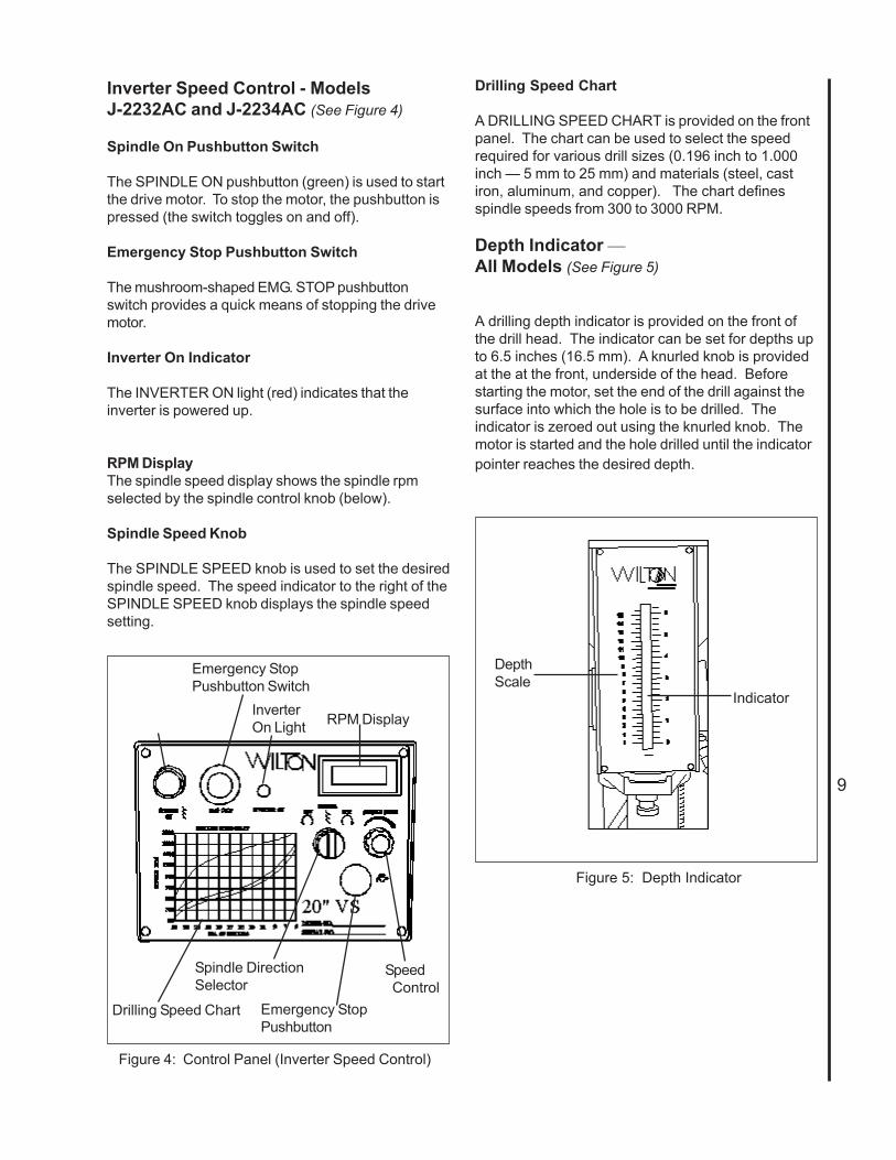
Figure 4: Control Panel (Inverter Speed Control)
Drilling Speed Chart
A DRILLING SPEED CHART is provided on the frontpanel. The chart can be used to select the speedrequired for various drill sizes (0.196 inch to 1.000inch — 5 mm to 25 mm) and materials (steel, castiron, aluminum, and copper). The chart definesspindle speeds from 300 to 3000 RPM.
Depth Indicator —All Models (See Figure 5)
A drilling depth indicator is provided on the front ofthe drill head. The indicator can be set for depths upto 6.5 inches (16.5 mm). A knurled knob is providedat the at the front, underside of the head. Beforestarting the motor, set the end of the drill against thesurface into which the hole is to be drilled. Theindicator is zeroed out using the knurled knob. Themotor is started and the hole drilled until the indicatorpointer reaches the desired depth.
Inverter Speed Control - ModelsJ-2232AC and J-2234AC (See Figure 4)
Spindle On Pushbutton Switch
The SPINDLE ON pushbutton (green) is used to startthe drive motor. To stop the motor, the pushbutton ispressed (the switch toggles on and off).
Emergency Stop Pushbutton Switch
The mushroom-shaped EMG. STOP pushbuttonswitch provides a quick means of stopping the drivemotor.
Inverter On Indicator
The INVERTER ON light (red) indicates that theinverter is powered up.
RPM DisplayThe spindle speed display shows the spindle rpmselected by the spindle control knob (below).
Spindle Speed Knob
The SPINDLE SPEED knob is used to set the desiredspindle speed. The speed indicator to the right of theSPINDLE SPEED knob displays the spindle speedsetting.
Figure 5: Depth Indicator
DepthScale
IndicatorInverterOn Light RPM Display
Emergency StopPushbutton
Drilling Speed Chart
Spindle DirectionSelector
Emergency StopPushbutton Switch
Speed Control

10
Replacement of Drive Belt
WARNING: MAKE SURE TO DISCONNECTELECTRICAL POWER TO THE DRILL PRESS TOAVOID THE POSSIBILITY OF INADVERTENTOPERATION AND EXPOSURE TO POTENTIALLYLETHAL VOLTAGE LEVELS.
Manual Speed Control -Models J-2221VS and J-2223VS1. Start drill press. Set speed control to highest
speed. Stop drill press.2. Disconnect electrical power by setting drill press
circuit breaker to OFF.3. Remove head cover.4. Remove belt. (With speed control setting at the
highest speed, the belt should be loose enough toremove.)
5. Install the replacement belt. Install the headcover.
6. Set the drill press circuit breaker ON.7. Operate the drill press to verify correct operation.
Inverter Speed Control -Models J-2232AC and J-2234AC1. Disconnect electrical power by setting drill press
circuit breaker to OFF.2. Remove pan screws from small cover (around
column). Remove pan screws and eight boltsfrom head cover.
3. Loosen set screw and remove shift lever.4. Remove plastic spindle cup.5. Remove head cover. Leave small cover in place.6. Disconnect electrical wiring from motor junction
box. Remove motor from mounting plate.7. Remove motor mounting plate.6. Remove three screws from pulley covers (discs).
Remove used belt. Install the replacement belt.8. Install pulley covers and secure with three screws
in each pulley cover.9. Install motor mounting plate. Install motor and.
connect electrical wiring (refer to WiringDiagram section for wiring details).
10. Install the head cover and secure with panscrews and eight bolts.
11. Secure small head cover to head cover using panscrews.
12. Set the drill press circuit breaker ON.13. Operate the drill press to verify correct operation.
Replacement of Motor
WARNING: MAKE SURE TO DISCONNECTELECTRICAL POWER TO THE DRILL PRESS TOAVOID THE POSSIBILITY OF INADVERTENTOPERATION AND EXPOSURE TO POTENTIALLYLETHAL VOLTAGE LEVELS.
Manual Speed Control -Models J-2221VS and J-2223VS1. Remove drive belt (refer to Replacement Of
Drive Belt).2. Disconnect electrical wiring from motor junction
box.3. Remove nuts from mounting studs securing
motor to drill head. Remove motor.4. Remove upper and lower pulleys and related
components from motor shaft.5. Install upper and lower pulleys and related
components on replacement motor shaft.6. Install motor on mounting studs and secure with
nuts.7. Connect electrical wiring (refer to Wiring
Diagram section for wiring details).8. Install drive belt (refer to Replacement Of Drive
Belt).9. Operate drill press to verify proper operation.
Inverter Speed Control -Models J-2232AC and J-2234AC
Refer to Replacement Of Drive Belt for instructionsfor removal of the drive motor.
LubricationFollowing are lubrication recommendations for drillpress components.
Manual Speed Control -Models J-2221VS and J-2223VS1. Spindle pulley drive: Lubricate spindle splines
occasionally with light grease.2. Quill and column: Lubricate with light film of
oil.3. Lift rack: Lubricate regularly with SAE 20 oil
(clean rack with kerosene before applying oil).4. Variable drive:
a. Speed control fork: service oil hole withSAE 20 oil once a week.
b. Countershaft spindle and push rod:lubricate with SAE 20 oil occasionally.
c. Speed control handle cam: clean andgrease with medium cup grease annually.
Maintenance

11
WARNING: CHANGE THE RADIAL POSITION OFTHE DRILL HEAD ONLY IF THE DRILL PRESSBASE IS SECURED TO THE FLOOR. SWINGINGTHE DRILL HEAD WITHOUT THE BASE BEINGSECURED TO THE FLOOR WILL CAUSE THEDRILL PRESS TO BECOME UNSTABLE AND TIPOVER RESULTING IN INJURY AND/OR DAMAGETO THE MACHINE.
Radial Adjustment of Head (All Models)The radial position of the drill head can be changedto accommodate the drilling of a hole that may beoffset from the center of the table. Reposition the drillhead as follows:1. Loosen the two clamping hex nuts using the hex
socket wrench provided with the machine.2. The swing the drill head to the desired position.3. Tighten the two clamping nuts.
Adjustment of Speed Pickup(Manual Models J-2221AC and J-2223AC)1. Loosen screws securing speed pickup (ref. 56-
1) to bracket (ref. 56-2).2. Adjust the speed pickup gap to approximately
1/8-inch.3. Operate drill press to verify that speed readout is
operating correctly.(Inverter Models J-2232AC and J-2234AC)1. Loosen screws securing speed pickup (ref.
68A) to bracket (ref. 70A) on drill head.2. Adjust the speed pickup gap to approximately
1/8-inch.3. Operate drill press to verify that speed readout is
operating correctly.
Figure 6: Oil Level Sight Gauge and Fill Tube Figure 7: Table Adjustment
Inverter Speed Control -Models J-2232AC and J-2234AC1. Spindle pulley drive: Lubricate spindle splines
occasionally with light grease.2. Quill and column: Lubricate with light film of
oil.3. Lift rack: Lubricate regularly with SAE 20 oil
(clean rack with kerosene before applying oil).4. Variable speed drive:
a. Periodically check oil level in sight gaugeon (left side of head) (refer to Figure 6).
b. If level is below centerline of sight gauge,add oil.
c. To add oil, remove oil fill tube cover plate.Pull fill tube out of hole in head cover.
d. Add SAE 20 oil to bring oil level up to thecenterline of the sight gauge.
e. Put end of fill tube back through hole inhead cover. Install fill tube cover andsecure with two screws.
Machine AdjustmentsTable Adjustment (See Figure 7)
The table can be raised or lowered to accommodatethe height of the workpiece. To raise or lower thetable, loosen the table lock using the hand crank.Then use the hand crank to move the table to thedesired height. Then lock the table in positon.
Head Adjustment
Table Clamping Handle Table RaisingSquare Drives
Oil Fill Tube
Sight Gauge

12
Feeds for DrillingThe feed of a drill is governed by the size of the tooland the material drilled. Because the feed ratepartially determines the rate of production and also isa factor in tool life, it should be chosen carefully foreach job. In general, the most effective feeds will befound in the following ranges:
Diameter of Drill Feed per Revolution(inches) (inches)
Under 1/8 .....................0.001 to 0.0021/8 to 1/4 ......................0.002 to 0.0041/4 to 1/2 ......................0.004 to 0.0071/2 to 5/8 ......................0.007 to 0.015
Indication of Extreme Speeds and Feeds
A drill that splits up the web is evidence of too muchfeed or insufficient tip clearance at the center as aresult of improper grinding. The rapid wearing awayof the extreme outer corners of the cutting edgesindicates that the speed is too high. A drill chippingor braking out at the cutting edges indicates thateither the feed is too heavy or the drill has beenground with too much tip clearance.
Speeds for High Speed Steel DrillsSpeed
Material In SFPM
Alloy Steel — 300 to 400 Brinell ......................20 - 30Stainless Steel .................................................30 - 40Automotive Steel Forgings ...............................40 - 50Tool Steel, 1.2C ...............................................50 - 60Steel, .4C to .5C .............................................70 - 80Mild Machinery Steel, .2C to .3C................... 80 - 110Hard Chilled Cast Iron .....................................30 - 40Medium Hard Cast Iron ................................. 70 - 100Soft Cast Iron ............................................. 100 - 150Malleable Iron .................................................80 - 90High Nickel Steel or Monel ..............................40 - 50High Tensile Bronze ....................................... 70 -150Ordinary Brass and Bronze ........................ 200 - 300Aluminum and its Alloys .............................. 200 - 300Magnesium and its Alloys ............................ 250 - 400Slate, Marble, and Stone .................................. 15 -25Plastics and similar material (Bakelite) ........ 100 - 150Wood ........................................................... 300 -400Titanium Alloys ................................................10 - 25Titanium Alloy Sheet ........................................50 - 60
In cases where carbon steel drills are applicable, thedrill should be run at speeds of from 40 to 50 percentof those given above.
Operating PrecautionsThe following operating and safety precautions mustbe observed in order to avoid harm to the operator ordamage to the drill press.1. The head assembly must be locked to the
column so the thrust produced by drilling will notforce the head assembly up the column.
2. The work table must be locked to the column soit will not be forced down the column.
3. Before drilling, release the quill lock nut topermit free travel of the quill.
4. Be sure the belt is tightened to the propertension.
5. DO NOT start to drill the workpiece until makingcertain the workpiece is held down securely.
6. MAKE SURE THE DRIVE MOTOR IS RUN-NING BEFORE turning the speed controlhandwheel in either direction.
7. Point of operation protection is required formaximum safety. This remains the responsibil-ity of the user/purchaser since conditions differbetween jobs.
8. Make sure the drill is secured in the spindle orcheck before attempting to use the drill press.
9. Make sure the spindle taper is clean and free ofburrs, scoring, and galling to assure maximumgripping.
10. Lock the quill in position when using and side-loaded tool.
Drilling Recommendations
Speeds for Drilling
The speed of a drill is usually measured in terms ofthe rate at which the outer periphery of the toolmoves in relation to the work being drilled. Thecommon term for this is Surface Feet per Minute(SFM). The relationship of SFM is expressed in thefollowing formulas:
SFM = 0.26 X rpm X Drill Diameter (in inches)RPM = 3.8 x ________SFM__________ Drill diameter (in inches)
In general, the higher the speed the shorter the drilllife. Operating at the low end of the speed range fora particular material will result in longer life. The mostefficient speed for operating a drill depends on manyvariables:1. Composition and hardness of material.2. Depth of the hole.3. Efficiency of the cutting fluid.4. Type and condition of the drilling machine.5. Desired quality of the hole.6. Difficulty of set-up.
13
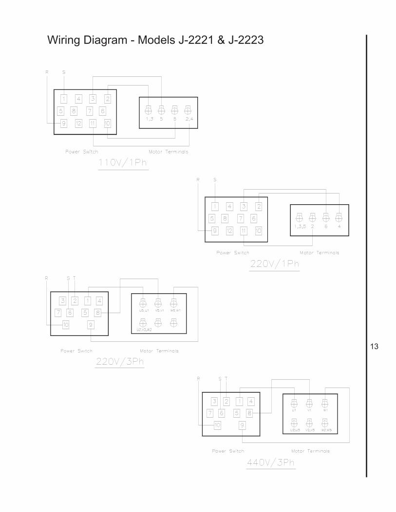
Wiring Diagram - Models J-2221 & J-2223

14
Wiring Diagram - Models J-2232AC & J-2234AC
LED Display Connection
0 220
AC Power Sensor
Volts- +Input
3 Phase 220/440
15
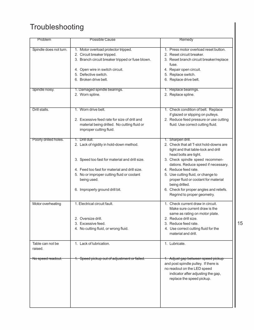
TroubleshootingProblem Possible Cause Remedy
Spindle does not turn. 1. Motor overload protector tripped. 1. Press motor overload reset button.2. Circuit breaker tripped. 2. Reset circuit breaker.3. Branch circuit breaker tripped or fuse blown. 3. Reset branch circuit breaker/replace
fuse.4. Open wire in switch circuit. 4. Repair open circuit.5. Defective switch. 5. Replace switch.6. Broken drive belt. 6. Replace drive belt.
Spindle noisy. 1. Damaged spindle bearings. 1. Replace bearings.2. Worn spline. 2. Replace spline.
Drill stalls. 1. Worn drive belt. 1. Check condition of belt. Replaceif glazed or slipping on pulleys.
2. Excessive feed rate for size of drill and 2. Reduce feed pressure or use cuttingmaterial being drilled. No cutting fluid or fluid. Use correct cutting fluid.improper cutting fluid.
Poorly drilled holes. 1. Drill dull. 1. Sharpen drill.2. Lack of rigidity in hold-down method. 2. Check that all T-slot hold-downs are
tight and that table-lock and drillhead bolts are tight.
3. Speed too fast for material and drill size. 3. Check spindle speed recommen-dations. Reduce speed if necessary.
4. Feed too fast for material and drill size. 4. Reduce feed rate.5. No or improper cutting fluid or coolant 5. Use cutting fluid, or change to
being used. proper fluid or coolant for materialbeing drilled.
6. Improperly ground drill bit. 6. Check for proper angles and reliefs.Regrind to proper geometry.
Motor overheating 1. Electrical circuit fault. 1. Check current draw in circuit.Make sure current draw is thesame as rating on motor plate.
2. Oversize drill. 2. Reduce drill size.3. Excessive feed. 3. Reduce feed rate.4. No cutting fluid, or wrong fluid. 4. Use correct cutting fluid for the
material and drill.
Table can not be 1. Lack of lubrication. 1. Lubricate.raised.
No speed readout. 1. Speed pickup out of adjustment or failed. 1. Adjust gap between speed pickupand post spindle pulley. If there isno readout on the LED speed
indicator after adjusting the gap,replace the speed pickup.

16
Optional EquipmentCoolant System Installation
1. Remove the large reservoir cover plate from themachine base. Tap 1/4-20 threads in the 4 pilot holes.Install the cover plate back onto the machine base.2. Insert the pump into the opening, utilize thescrews from the small round cover plate to fasten thepump to the base.3. Position the power switch and valve bracket on thespindle casting. Mark mounting hole locations anddrill holes. (Refer to Figure 8).Note: Mount components near the lower edge of thespindle casting. Do not mount componets above theline shown in Figure 9.4. Install the power switch and valve bracket with theprovided fastener hardware.
Figure: 8 Suggested installation
5. Install the 3/8-inch hose barb to the coolant pump.If needed apply a light coat of pipe sealant or Teflontape to the threads to prevent leakage.6. Mount the flow valve to the bracket, connect thesupply hose to the pump and valve, use hose clampsat the ends.7. Install the flexible nozzle to the flow valve.8. Install the 1/2-inch hose barb to the worktable,seal threads if needed. Connect the return hose.9. Connect the power cord to a suitable source andground (refer to General Electrical Cautions).10. Fill the reservoir with appropriate machiningcoolant.
Figure 9: Installation Detail
Do not mount components above this line.
Flow valvemounting bracket.
Power switch - mountingplate flush with bottomedge of spindle casting.

17
Replacement PartsThis section provides exploded view illustrations that show the replacement parts for JET Model J-2221VS,J-2223VS, J-2232AC, and J-2234AC 20-Inch Drill Presses. Also provided are parts listings that provide partnumber, description, and quantity. The item numbers shown on the illustration relate to the item number in thefacing page of the parts listing.
Separate exploded views and parts listings are provided for the drill heads for manual speed control drill presses(Models J-2221VS and J-2223VS) and the inverter speed control drill presses (Models J-2232AC and J-2234AC).The exploded view and parts listing for the drill press spindle components, and the table, base, and columnapply to all models.
Order replacement parts from:
WMH TOOL GROUP427 New Sanford RoadLaVergne, Tennessee 30786Phone: 800-274-6848
Identify the replacement part by the part number shown in the parts listing. Be sure to include the modelnumber and serial number of your machine when ordering replacement parts to assure that you will receive thecorrect part.

18
Exploded View — Drill Head — Manual Speed Control(Models J-2221VS and J-2223VS)
19
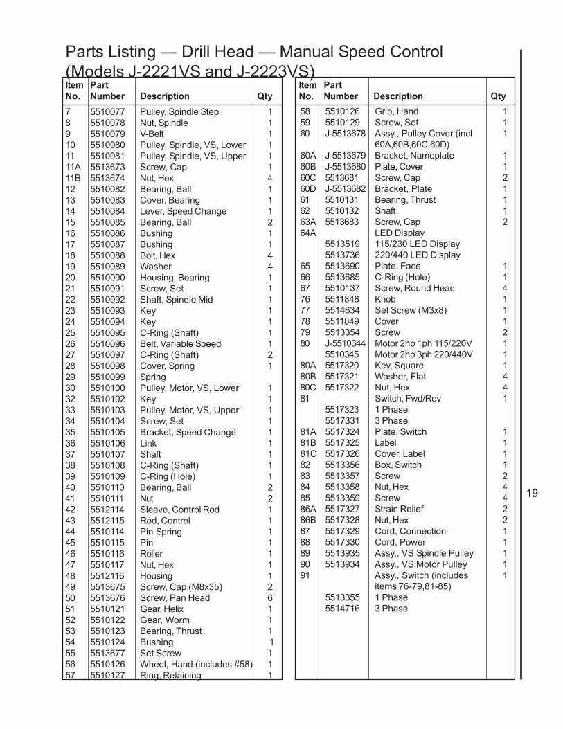
7 5510077 Pulley, Spindle Step 18 5510078 Nut, Spindle 19 5510079 V-Belt 110 5510080 Pulley, Spindle, VS, Lower 111 5510081 Pulley, Spindle, VS, Upper 111A 5513673 Screw, Cap 111B 5513674 Nut, Hex 412 5510082 Bearing, Ball 113 5510083 Cover, Bearing 114 5510084 Lever, Speed Change 115 5510085 Bearing, Ball 216 5510086 Bushing 117 5510087 Bushing 118 5510088 Bolt, Hex 419 5510089 Washer 420 5510090 Housing, Bearing 121 5510091 Screw, Set 122 5510092 Shaft, Spindle Mid 123 5510093 Key 124 5510094 Key 125 5510095 C-Ring (Shaft) 126 5510096 Belt, Variable Speed 127 5510097 C-Ring (Shaft) 228 5510098 Cover, Spring 129 5510099 Spring30 5510100 Pulley, Motor, VS, Lower 132 5510102 Key 133 5510103 Pulley, Motor, VS, Upper 134 5510104 Screw, Set 135 5510105 Bracket, Speed Change 136 5510106 Link 137 5510107 Shaft 138 5510108 C-Ring (Shaft) 139 5510109 C-Ring (Hole) 140 5510110 Bearing, Ball 241 5510111 Nut 242 5512114 Sleeve, Control Rod 143 5512115 Rod, Control 144 5510114 Pin Spring 145 5510115 Pin 146 5510116 Roller 147 5510117 Nut, Hex 148 5512116 Housing 149 5513675 Screw, Cap (M8x35) 250 5513676 Screw, Pan Head 651 5510121 Gear, Helix 152 5510122 Gear, Worm 153 5510123 Bearing, Thrust 154 5510124 Bushing 155 5513677 Set Screw 156 5510126 Wheel, Hand (includes #58) 157 5510127 Ring, Retaining 1
58 5510126 Grip, Hand 159 5510129 Screw, Set 160 J-5513678 Assy., Pulley Cover (incl 1
60A,60B,60C,60D)60A J-5513679 Bracket, Nameplate 160B J-5513680 Plate, Cover 160C 5513681 Screw, Cap 260D J-5513682 Bracket, Plate 161 5510131 Bearing, Thrust 162 5510132 Shaft 163A 5513683 Screw, Cap 264A LED Display
5513519 115/230 LED Display5513736 220/440 LED Display
65 5513690 Plate, Face 166 5513685 C-Ring (Hole) 167 5510137 Screw, Round Head 476 5511848 Knob 177 5514634 Set Screw (M3x8) 178 5511849 Cover 179 5513354 Screw 280 J-5510344 Motor 2hp 1ph 115/220V 1
5510345 Motor 2hp 3ph 220/440V 180A 5517320 Key, Square 180B 5517321 Washer, Flat 480C 5517322 Nut, Hex 481 Switch, Fwd/Rev 1
5517323 1 Phase5517331 3 Phase
81A 5517324 Plate, Switch 181B 5517325 Label 181C 5517326 Cover, Label 182 5513356 Box, Switch 183 5513357 Screw 284 5513358 Nut, Hex 485 5513359 Screw 486A 5517327 Strain Relief 286B 5517328 Nut, Hex 287 5517329 Cord, Connection 188 5517330 Cord, Power 189 5513935 Assy., VS Spindle Pulley 190 5513934 Assy., VS Motor Pulley 191 Assy., Switch (includes 1
items 76-79,81-85)5513355 1 Phase5514716 3 Phase
Parts Listing — Drill Head — Manual Speed Control(Models J-2221VS and J-2223VS)Item PartNo. Number Description Qty
Item PartNo. Number Description Qty

20
Exploded View — Drill Head — Inverter Speed Control(Models J-2232AC and J-2234AC)

21
Item PartNo. Number Description Qty
1 J-5517332 Casting, Head 12 5510142 Window, Oil 13 5510143 Bearing, Ball 14 5510144 Ring, Retaining 15 5510145 Gear (32T) 16 5510146 Key 17 5510147 Shaft, Drive (13T) 18 5510148 Bearing, Ball 19 5510149 Ring, Retaining 1
10 5510150 Bearing, Ball 111 5510151 Ring, Retaining 112 5510153 Gear (55T) 113 5510152 Screw, Set 114 5510155 Spring 115 5510154 Ball, Steel 116 5510159 Key 117 5517333 Plug, Drain, 3/8 NPT 118 5510158 Gear (18T) 120 5510160 Key 121 5510161 Shaft, Mid 122 5510162 Key 123 5510163 Ring, Retaining 224 5510164 Bearing, Ball 125 5510165 Pin 126 5510166 Bar 126-1 5517334 Ring 127 5510167 Nut, Hex 128 5510168 Washer, Spring 129 5510169 Block, Speed Change 130 5510170 Bar, Gear 131 5510171 Screw, Set 132 5517335 Lever, Speed 133 5517336 Ring, Retaining 134 5510173 Seal, Oil 135 5510177 Shaft, Gear (18T) 136 5517337 Nut, Hex 137 5517338 Screw, Cap 138 5510178 Screw, Set 139 5517339 Cover (Top), Gearbox 140 5510180 Fitting, Fill, Oil 140-1 5517340 Tube, Fill 141 5510181 Seal, Oil 142 5510182 Bolt 143 5510183 Seal, Oil 144 5510184 Seal, Oil 144-1 5517341 Ring, Retaining 145 5510185 Screw, Set 146 5510186 Pulley, Drive 147 5517342 Pulley, Spindle, 48T 148 5517343 Belt, 720x8 149 5510189 Bolt, Hex, M6x30 249-1 5517344 Screw, Flat Head, M5x10 250 5517345 Washer, Flat, M6 251 5517346 Bracket 1
Item PartNo. Number Description Qty
51-1 5517347 Housing, Bearing 151-2 5517348 Bearing, Ball, 6002ZZ 1 52 5510192 Key 1 53 Motor, 2hp, 3ph 1
J-5517349 220VJ-5517350 440V
54 5510194 Washer 455 5510195 Screw 456 5510204 Switch, E-stop 1 56-1 5510197 Proximity Switch, Speed 1 56-2 5510198 Bracket, Proximity Switch 157 5510201 Light, Indicator 159 5510199 Switch, Pump Selector 160 5510200 Switch, Forward/Reverse 161 5510196 Potentiometer, Speed Control 1 62 5510202 Switch, Pushbutton, Green 163 5510206 Screw 464 5517351 Panel, Control 1 64-1 5517352 Bracket, Plate 165 5510209 Screw, Pan Head 266 5510210 Cover, Oil Filler 167 J-5517353 Cover, Pulley 1 67-1 5517354 Plate, Top 167-2 5510213 Plate, Fixed 167-3 5517355 Plate, Fixed 167-4 5510215 Screw, Pan Head 267-5 5517356 Screw 267-6 5517357 Screw 267-7 5517358 Washer 667-8 5510214 Screw, Pan Head 468 5510216 Washer, Spring 269 5510217 Screw 270 J-5517359 Enclosure (w/door & latch) 171 5510219 Screw 472 5510220 Bolt 4 73 5517360 Washer 474 5510222 Relief, Cable 174-1 5517361 Relief, Cable 175 5510223 Cable, Electric 175-1 5517362 Cable, Electric 176 5510224 Cover, Window 177 5517363 Panel, Component Mounting 179 5510227 Board, Insulation 180 5510228 Fuse Block 181 5510229 Transformer 1 82 5517364 Washer 4 83 5517365 Screw, Pan Head 484 5517366 Screw, Cap 484-1 5517367 Washer, Lock 484-2 5517368 Nut, Hex 485 Inverter, Delta, M-type 1
5510233 220V, 3ph5512670 440V, 3ph
Parts Listing — Drill Head — Inverter Speed Control(Models J-2232AC and J-2234AC)

22
Item PartNo. Number Description Qty
85-1 5517371 Washer, Flat 485-2 5517372 Screw 486 5517373 Sub-Panel 186-1 5517374 Screw 487 5510235 Terminal Block 188 5517375 Rail, Mounting 189 5510237 Contactor 189-1 5510238 Relay 190 5510240 Relay 194 5510242 Screw 295 5510243 Screw 296 5510244 Microswitch 297 5510245 Bracket, Microswitch 298 5510246 Rod, Microswitch Support 199 Electrical Enclosure Complete 1
5514648 220V, 3Ph5514649 440V 3Ph
105 LED Display 15513519 115/220 LED Display5513736 220/440 LED Display
106 5513683 Screw, Cap 2107 5515285 Cap, Spindle 1
Parts Listing — Drill Head — Inverter Speed Control(Models J-2232AC and J-2234AC)

23
Exploded View — Spindle Components (All Models)

24
Item PartNo. Number Description Qty
1 J-5517332 Casting, Head 12 5517376 Bolt, Hex, Shoulder 2
2-1 5517377 Spring 23 5517378 Rod, Cam Lock 24 5510250 Nut, Hex 25 5510251 Wrench, Hex Head 17 5510252 Screw, Set 18 5517379 Washer, External Tooth 1
10 5510253 Spindle 111 5510254 Bearing, Ball 212 5510255 Spacer 114 5510256 C-Ring 115 5510258 Screw, Set 116 5510259 Pin, Roll 126 5510261 Screw, Socket Head 127 5510262 Washer 128 5510263 Container, (includes #29) 129 5510263 Spring, Return 130 5510265 Screw, Socket Head 331 5510266 Seat, Spring 132 5510267 Pin, Spring 136 5513770 Washer, Rubber 137 J-5513771 Band, Quill 1
37A 5517380 Bolt, Hex, Shoulder 137B 5517381 Washer, Flat 237C 5517382 Nut, Hex 138 5513772 Nut, Lock 239 5513773 Bearing, Ball 140 5513774 Pin, Drift 141 5510268 Quill 142 5510269 Bearing, Ball 143 5510270 Spindle 144 5510271 Seal, Oil 145 5510272 Nut 146 5510273 Rod, Depth 148 5510274 Nut 149 5510275 Nut 150 5510276 Retainer 151 5510277 Pin, Spring 153 5510278 Scale, Depth 158 5510279 Screw, Round Head Cap 460 5510280 Key 161 5510281 Screw, Socket Head 362 5510282 Key 163 5510283 Shaft, Feed 166 5510284 Seat, Feed Shaft 1
Parts Listing — Spindle Components (All Models)
Item PartNo. Number Description Qty
67 J-5510285 Hub 168 5510286 Spoke 3
68A 5513515 Pickup, Magnetic 168B 5513687 Screw, Pan Head 269 5510287 Knob 3
69A 5517383 Plate, Adjustable 169B 5517384 Bracket, Mag. Pickup 169C 5513689 Screw, Cap 169D 5517385 Washer, Flat 169E 5517386 Nut, Hex 1 70 5517387 Screw 2 71 5511849 Cover 1 72 5513354 Screw 4

25
Exploded View - Table and Base (All Models)

26
Item PartNo. Number Description Qty
1 J-5510288 Base 12 J-5510289 Plate, Coolant Cover 13 5510456 Pump, Coolant, 115V, 1P 1
5512103 Pump, Coolant, 220/440V 3P 14 5510291 Bolt, Hex 45 5517388 Screw, Pan Head 36 5510293 Seat, Ball 17 5510294 Screw, Set 4
7-1 5517389 Block, Brass 48 5510295 Bearing, Ball 19 J-5510296 Ring, Lock 1
9-1 5517390 Pin 110 5516859 Shaft, Table Raiser 111 5510298 Pin, Spring 412 5516858 Shaft, Table Clamp 113 5516860 Coupling, Table Raiser 114 5510300 Screw, Socket Head 115 5510301 Nut 116 5510302 Rack 117 5514663 Gear, Bevel, Large 118 5517391 Housing, Bearing 1
18-1 5517392 Bearing, Ball, 6202ZZ 218-2 5517393 Washer 218-3 5510303 Screw, Cap 219 5510304 Gear, Bevel, Small 220 J-5510305 Bracket Cover 121 5510306 C-Ring 122 5510307 Bearing, Ball 123 5510308 Shaft 124 5510309 C-Ring 225 5510310 Screw, Socket Head 426 5510311 Shaft 127 5517395 Screw, Set 128 5510313 Key 129 5510314 Bearing 130 5510315 Worm, Table Raise 131 5510316 Key 132 5510317 Gear, Worm 133 5510318 Gear 134 5510319 Lock, Cam, Front 135 5510320 Lock, Cam, Rear 1
35-1 5517396 Spring 135-2 5517397 Screw, Cap, M6x25 135-3 5517398 Pin, 5x25 236 J-5510321 Crank, Table Raise 237 J-5510322 Table 1
37-1 5517399 Barb, Hose, 1/2" (return) 138 5510323 Column 139 5510324 Handle, Table Raise 140 5510325 Screw, Hex Head 1
40-1 5510334 Washer 1
Parts List - Table and Base (All Models)Item PartNo. Number Description Qty
41 5510326 Clamp 142 5510327 Screw, Pan Head 143 5510328 Hose, Vinyl, Clear, 3/8" 144 5510329 Barb, Hose, 3/8" (supply) 145 5512112 SHCS, #10-32 x 1" 446 5510331 Bracket, Mounting 147 5510332 Valve 148 5510333 Nozzle, Flexible 149 5517400 Screw, Pan Head 150 5517401 Hose, Vinyl, Clear, 1/2" 151 5517402 Clamp, Hose 152 5517403 Screw, Set, 1/2 x 1 253 5517404 Plug, Drain, 3/8 NPT 154 5517405 Pin, Spring, 4x50 155 J-5517406 Collar, Rack 156 5513932 Assembly, Table Raiser 157 9057451 Washer, Flat, #10 258 5517488 Nut, Hex, 1/2" 159 5517489 Cord, Power 160 5517490 Assy., Switch 161 Cord, Pump 1
5517491 1 Phase5517492 3 Phase
62 5517493 Clamp, Hose, Rad. Type 263 9058341 Washer, Lock, #10 464 5517628 Nut, Hex, #10-32 465 Coolant System Complete 1
5512104 1/8 HP, 115/220V, 1 Phase5508071 1/8 HP, 220/440V, 3 Phase


WMH Tool Group427 New Sanford Road
LaVergne, Tennessee 30786Ph: 800-274-6848
www.wmhtoolgroup.com