Embed Size (px)
Citation preview
Operating Instructions and Parts Manual Variable Speed Turret Mill Model JTM-4VS
Shown with optional accessories X-Axis Table Powerfeed and DRO
WALTER MEIER (Manufacturing) Inc.
427 New Sanford Road LaVergne, Tennessee 37086 Part No. M-690182 Ph.: 800-274-6848 Revision G 06/2010 www.waltermeier.com Copyright © 2010 Walter Meier (Manufacturing) Inc.

2
Warranty and Service Walter Meier (Manufacturing) Inc., warrants every product it sells. If one of our tools needs service or repair, one of our Authorized Service Centers located throughout the United States can give you quick service. In most cases, any of these Walter Meier Authorized Service Centers can authorize warranty repair, assist you in obtaining parts, or perform routine maintenance and major repair on your JET® tools. For the name of an Authorized Service Center in your area call 1-800-274-6848. MORE INFORMATION Walter Meier is consistently adding new products to the line. For complete, up-to-date product information, check with your local Walter Meier distributor, or visit waltermeier.com. WARRANTY JET products carry a limited warranty which varies in duration based upon the product (MW = Metalworking, WW = Woodworking).
WHAT IS COVERED? This warranty covers any defects in workmanship or materials subject to the exceptions stated below. Cutting tools, abrasives and other consumables are excluded from warranty coverage. WHO IS COVERED? This warranty covers only the initial purchaser of the product. WHAT IS THE PERIOD OF COVERAGE? The general JET warranty lasts for the time period specified in the product literature of each product. WHAT IS NOT COVERED? Five Year Warranties do not cover woodworking (WW) products used for commercial, industrial or educational purposes. Woodworking products with Five Year Warranties that are used for commercial, industrial or education purposes revert to a One Year Warranty. This warranty does not cover defects due directly or indirectly to misuse, abuse, negligence or accidents, normal wear-and-tear, improper repair or alterations, or lack of maintenance.
HOW TO GET SERVICE The product or part must be returned for examination, postage prepaid, to a location designated by us. For the name of the location nearest you, please call 1-800-274-6848. You must provide proof of initial purchase date and an explanation of the complaint must accompany the merchandise. If our inspection discloses a defect, we will repair or replace the product, or refund the purchase price, at our option. We will return the repaired product or replacement at our expense unless it is determined by us that there is no defect, or that the defect resulted from causes not within the scope of our warranty in which case we will, at your direction, dispose of or return the product. In the event you choose to have the product returned, you will be responsible for the shipping and handling costs of the return.
HOW STATE LAW APPLIES This warranty gives you specific legal rights; you may also have other rights which vary from state to state.
LIMITATIONS ON THIS WARRANTY WALTER MEIER (MANUFACTURING) INC., LIMITS ALL IMPLIED WARRANTIES TO THE PERIOD OF THE LIMITED WARRANTY FOR EACH PRODUCT. EXCEPT AS STATED HEREIN, ANY IMPLIED WARRANTIES OR MERCHANTABILITY AND FITNESS ARE EXCLUDED. SOME STATES DO NOT ALLOW LIMITATIONS ON HOW LONG THE IMPLIED WARRANTY LASTS, SO THE ABOVE LIMITATION MAY NOT APPLY TO YOU. WALTER MEIER SHALL IN NO EVENT BE LIABLE FOR DEATH, INJURIES TO PERSONS OR PROPERTY, OR FOR INCIDENTAL, CONTINGENT, SPECIAL, OR CONSEQUENTIAL DAMAGES ARISING FROM THE USE OF OUR PRODUCTS. SOME STATES DO NOT ALLOW THE EXCLUSION OR LIMITATION OF INCIDENTAL OR CONSEQUENTIAL DAMAGES, SO THE ABOVE LIMITATION OR EXCLUSION MAY NOT APPLY TO YOU. Walter Meier sells through distributors only. The specifications in Walter Meier catalogs are given as general information and are not binding. Members of Walter Meier reserve the right to effect at any time, without prior notice, those alterations to parts, fittings, and accessory equipment which they may deem necessary for any reason whatsoever. JET® branded products are not sold in Canada by Walter Meier.

3
Table of Contents Warranty and Service .................................................................................................................................2 Introduction ...............................................................................................................................................7 Specifications ............................................................................................................................................7 Unpacking .................................................................................................................................................8
Contents of the Shipping Container..........................................................................................................8 Set-up and Installation................................................................................................................................9
Preparing the Milling Machine for Service.................................................................................................9 JTM-4VS Dimensions............................................................................................................................... 10 JTM-4VS Overview and Terminology ........................................................................................................ 11 Electrical Connections .............................................................................................................................. 12
General Electrical Cautions ................................................................................................................ 12 Wire Sizes ........................................................................................................................................ 12
Lubrication ........................................................................................................................................... 12 Operating Instructions .............................................................................................................................. 12
Operating Controls ............................................................................................................................... 12 Motor Switch ........................................................................................................................................ 12 Variable Speed Control ......................................................................................................................... 13 Spindle Brake....................................................................................................................................... 14 High-Neutral-Low Shift Lever................................................................................................................. 14 Quill Power Feed Lever......................................................................................................................... 14 Feed Rate Lever................................................................................................................................... 14 Feed Trip Cam Lever ............................................................................................................................ 15 Feed Direction Control .......................................................................................................................... 15 Coarse Feed Handle............................................................................................................................. 15 Quill Lock Lever.................................................................................................................................... 15 Micrometer Adjusting Nut ...................................................................................................................... 15 Fine Feed Handwheel ........................................................................................................................... 15 Depth Scale and Stop ........................................................................................................................... 16 Power Feed Operation .......................................................................................................................... 16 Draw Bar Operation - Changing Tooling ................................................................................................. 17 Clamping Work Piece to the Table ......................................................................................................... 17
Adjustments ............................................................................................................................................ 17 Mill Head – Left/Right Adjustment .......................................................................................................... 17 Mill Head – Fore/Aft Adjustment ............................................................................................................ 18 Positioning the Ram.............................................................................................................................. 19
Positioning the Ram Fore and Aft ....................................................................................................... 19 Positioning the Ram on its Turret........................................................................................................ 19
Gib Adjustment..................................................................................................................................... 19 Adjustment of Knee Gib ..................................................................................................................... 19 Adjustment of Saddle Gib .................................................................................................................. 19 Adjustment of Table Gib .................................................................................................................... 19
Power Feed Trip Lever Mechanism........................................................................................................ 20 Table Lead Screw Backlash Adjustment ................................................................................................ 20
Cross Feed Backlash Adjustment ....................................................................................................... 20 Longitudinal Backlash Adjustment ...................................................................................................... 20
Maintenance............................................................................................................................................ 22 Lubrication ........................................................................................................................................... 22
Periodic Maintenance Requirements .................................................................................................. 22 Replacement of Drive Motor .................................................................................................................. 23 Replacement of Vari-Speed Belt ............................................................................................................ 24 Replacement of Brake Shoes, Springs and/or Timing Belt ....................................................................... 24 Replacement of Quill Feed Clock Spring ................................................................................................ 25
Replacement Parts .................................................................................................................................. 25 Head Assembly .................................................................................................................................... 26 Parts List for Head Assembly ................................................................................................................ 27 Spindle Assembly ................................................................................................................................. 30 Base Assembly .................................................................................................................................... 34 Parts List for Base Assembly ................................................................................................................. 35

4
Lead Screw Assembly .......................................................................................................................... 37 One-Shot Lubrication System ................................................................................................................ 38 Electrical Connections – Single Phase only ............................................................................................ 39 Electrical Connections – 3 Phase only ................................................................................................... 40

5
Warning
1. Read and understand the entire owner’s manual before attempting assembly or operation.
2. Read and understand the warnings posted on the machine and in this manual. Failure to comply with all of these warnings may cause serious injury.
3. Replace the warning labels if they become obscured or removed.
4. This turret mill is designed and intended for use by properly trained and experienced personnel only. If you are not familiar with the proper and safe operation of a turret mill, do not use until proper training and knowledge have been obtained.
5. Do not use this turret mill for other than its intended use. If used for other purposes, WMH Tool Group disclaims any real or implied warranty and holds itself harmless from any injury that may result from that use.
6. Always wear approved safety glasses/face shields while using this turret mill. (Everyday eyeglasses only have impact resistant lenses; they are not safety glasses.)
7. Before operating this turret mill, remove tie, rings, watches and other jewelry, and roll sleeves up past the elbows. Remove all loose clothing and confine long hair. Non-slip footwear or anti-skid floor strips are recommended. Do not wear gloves.
8. Wear ear protectors (plugs or muffs) during extended periods of operation.
9. Some dust created by power sanding, sawing, grinding, drilling and other construction activities contain chemicals known to cause cancer, birth defects or other reproductive harm. Some examples of these chemicals are:
• Lead from lead based paint.
• Crystalline silica from bricks, cement and other masonry products.
• Arsenic and chromium from chemically treated lumber.
Your risk of exposure varies, depending on how often you do this type of work. To reduce your exposure to these chemicals, work in a well-ventilated area and work with approved safety equipment, such as face or dust masks that are specifically designed to filter out microscopic particles.
10. Do not operate this machine while tired or under the influence of drugs, alcohol or any medication.
11. Make certain the switch is in the OFF position before connecting the machine to the power supply.
12. Make certain the machine is properly grounded.
13. Make all machine adjustments or maintenance with the machine unplugged from the power source.
14. Remove adjusting keys and wrenches. Form a habit of checking to see that keys and adjusting wrenches are removed from the machine before turning it on.
15. Keep safety guards in place at all times when the machine is in use. If removed for maintenance purposes, use extreme caution and replace the guards immediately.
16. Some coolants used for machining contain chemicals that may be hazardous to your health if not used properly. Read and understand all information on the coolant container and protect yourself accordingly.
17. Check damaged parts. Before further use of the machine, a guard or other part that is damaged should be carefully checked to determine that it will operate properly and perform its intended function. Check for alignment of moving parts, binding of moving parts, breakage of parts, mounting and any other conditions that may affect its operation. A guard or other part that is damaged should be properly repaired or replaced.
18. Provide for adequate space surrounding work area and non-glare, overhead lighting.
19. Keep the floor around the machine clean and free of scrap material, oil and grease.
20. Keep visitors a safe distance from the work area. Keep children away.

6
21. Give your work undivided attention. Looking around, carrying on a conversation and “horse-play” are
careless acts that can result in serious injury.
22. Maintain a balanced stance at all times so that you do not fall or lean against the cutters or other moving parts. Do not overreach or use excessive force to perform any machine operation.
23. Use the right tool at the correct speed and feed rate. Do not force a tool or attachment to do a job for which it was not designed. The right tool will do the job better and more safely.
24. Use recommended accessories; improper accessories may be hazardous.
25. Maintain tools with care. Keep cutters sharp and clean for the best and safest performance. Follow instructions for lubricating and changing accessories.
26. Turn off the machine and disconnect from power before cleaning. Use a brush or compressed air to remove chips or debris — do not use your hands.
27. Do not stand on the machine. Serious injury could occur if the machine tips over.
28. Never leave the machine running unattended. Turn the power off and do not leave the machine until it comes to a complete stop.
29. Remove loose items and unnecessary work pieces from the area before starting the machine.
Familiarize yourself with the following safety notices used in this manual:
This means that if precautions are not heeded, it may result in minor injury and/or possible machine damage.
This means that if precautions are not heeded, it may result in serious or even fatal injury.

7
Introduction This manual is provided by Walter Meier (Manufacturing) Inc., covering the safe operation and maintenance procedures for a JET Model JTM-4VS Turret Milling Machine. This manual contains instructions on installation, safety precautions, general operating procedures, maintenance instructions and parts breakdown. This machine has been designed and constructed to provide years of trouble free operation if used in accordance with instructions set forth in this manual. If there are any questions or comments, please contact either your local supplier or Walter Meier. Walter Meier can also be reached at our web site: www.waltermeier.com.
Specifications Model Number ................................................................... JTM-4VS-1 ............................................JTM-4VS-3 Stock Number.......................................................................... 690180 ................................................ 690182 Spindle Taper ................................................................................R-8 ....................................................... R-8 Diameter of Quill (in.) ..................................................................3.375 .................................................... 3.375 Number of Spindle Speeds ...................................................... Variable ................................................ Variable Range of Spindle Speeds (RPM) ......................................... 60 to 4200 .............................................60 to 4200 Downfeeds per Revolution of Spindle (in.) ............ 0.0015, 0.003, 0.006 .............................. 0.0015, 0.003, 0.006 Spindle Travel (in.) ............................................................................ 5 ...........................................................5 Head Movement – Left and Right (deg.) ........................................... 90 ......................................................... 90 Head Movement – Fore and Aft (deg.).............................................. 45 ......................................................... 45 Maximum Distance Spindle to Table (in.) .................................... 17-1/2 ................................................... 17-1/2 Maximum Distance Spindle to Column (in.)....................................... 19 ......................................................... 19 Minimum Distance Spindle to Column (in.).................................... 4-1/2 ..................................................... 4-1/2 Collet Capacity (in.)................................................................ 1/8 – 7/8 ............................................... 1/8 – 7/8 Table Size (in.) .......................................................................... 9 x 49 ................................................... 9 x 49 Longitudinal Table Travel, maximum (in.) ......................................... 34 ......................................................... 34 Table Cross Travel, maximum (in.)................................................... 12 ......................................................... 12 Number of T-Slots ............................................................................. 3 ...........................................................3 T-Slot Size (WxD)(in.) ............................................................ 5/8 x 3/4 ................................................5/8 x 3/4 T-Slot Centers (in.)...................................................................... 2-1/2 ..................................................... 2-1/2 Table Load, maximum (lbs.) .......................................................... 660 ...................................................... 660 Knee Travel, maximum (in.) ....................................................... 14-1/2 ................................................... 14-1/2 Ram Travel, maximum (in.)........................................................ 13-3/8 ................................................... 13-3/8 Overall Dimensions (in.) ............................................ 66W x 63D x 85H .................................. 66W x 63D x 85H Motor ............................................... TEFC 2HP, 1PH, 115/230V, 60Hz ......... TEFC 3 HP, 3PH, 230/460V, 60Hz (prewired 230V) (prewired 230V) Net Weight, approx. (lbs.) ............................................................2,420 .................................................... 2,420
The above specifications were current at the time this manual was published, but because of our policy of continuous improvement, Walter Meier reserves the right to change specifications at any time and without prior notice, without incurring obligations.

8
Unpacking Open shipping container and check for shipping damage. Report any damage immediately to your distributor and shipping agent. Do not discard any shipping material until the Turret Mill is assembled and running properly.
Compare the contents of your container with the following parts list to make sure all parts are intact. Missing parts, if any, should be reported to your distributor. Read the instruction manual thoroughly for assembly, maintenance and safety instructions.
Contents of the Shipping Container Note: Some parts may be pre-installed on the mill. 1 Turret Mill (not shown) 1 Flat Way Cover 1 Pleated Way Cover 1 Draw Bar
3 Table Adjustment Handles 1 Tool Box, containing:
1 Hex Key Set (1.5-10mm) * 1 17/19mm Box Wrench * 1 Cross Point Screw Driver #2 * 1 Flat Blade Screw Driver #2 * 1 Plastic Oil Bottle * 1 Elevating Crank Handle 1 Handwheel 1 Coarse Feed Handle 1 Can White Touch Up Paint 1 Eye Bolt 1 Operator’s Manual (not shown) 1 Warranty Card (not shown) * parts with an asterisk are also included in the tool box service kit, p/n JTM4VS-TB.
Figure 1
Read and understand the entire contents of this manual before attempting set-up or
operation! Failure to comply may cause serious injury.
If your mill is supplied with an optional Table Powerfeed and/or DRO, be sure to consult the separate instruction materials that accompany them.

9
Set-up and Installation Preparing the Milling Machine for Service 1. Remove any crating which may be covering the
machine on the pallet.
2. Remove accessory items from the pallet or machine table. Compare these items with the list on the previous page.
3. Check the tightness of the lifting ring on the ram to be certain it is tight.
4. Check the tightness of the lock handles on the ram (see Figure 23) to be certain the ram is locked tight.
5. Remove the nuts and/or bolts, which secure the machine to the pallet.
6. Center an overhead crane or other suitable overhead lifting device and sling arrangement over the lifting ring.
Note: This machine weighs over 2400 pounds! Be certain the lifting arrangement is new or in excellent condition and has a safety factor that will account for age, difficulties in lifting, etc. When lifting using the ring, the machine will tip forward. If you wish, you can minimize this tipping by rigging a support sling over the front of the machine. Be careful when doing this, to prevent the sling from damaging any components on the front of the machine. Be sure to steady the mill to prevent it from spinning.
7. Lift the machine off the pallet no higher than necessary to clear the hold-down hardware, then pull the pallet out of the way. Do NOT get hands or feet underneath the machine when removing the pallet!
8. Put the machine base over the hold-down system where the machine will be spotted. Anchor bolts of sufficient size and length must be fastened to the floor according to the footprint of the mill. See diagram on page 10.
Note: The accompanying diagrams show you the maximum dimensions of the machines with the table, ram, etc., fully extended in all possible directions. When spotting the machine be certain to leave room not only for the machine itself, but also for operator clearance and clearance for workers servicing the machine, and any unusual sizes of workpieces that might extend off the machine’s table.
9. When the machine is over its anchors, level the machine using shims under the corners needing them. The machinist’s level used for leveling should be placed on the table. The table is the reference surface for both side-to-side and fore-
and-aft leveling. Be certain you get it level in BOTH directions.
Mill must be supported equally under all four corners. Failure to comply may cause the column to twist and put a bind in the table ways.
10. When the machine is level, secure the base to the anchor system.
IMPORTANT: Before attempting to raise the mill head, refer to Mill Head – Left/Right Adjustment in the Adjustments section for procedures to safely raise and set up the mill head.
11. Loosen the four hex head nuts (see A, Figure 22) about 1/4 turn each (counterclockwise), just enough to allow rotation of the head.
12. While assisting the worm mechanism by putting upward pressure on the motor by hand, use the wrench supplied with the machine to turn the worm nut and raise the head to upright position.
13. Tighten the headbolts slightly — not torqued — just snug.
14. Using mineral spirits or other cleaning solvent, clean all of the rust proofing from where it may have been applied. This is important; moving the table or any other components before removing the rust proofing will only put rust proofing where you don’t want it.
Some of the following steps may have already been performed on the machine. If so, ignore the instructions related to those particular steps. Otherwise, perform them in the order listed, referring to Figure 11 for any clarification.
15. Install the table traverse and cross-feed cranks on their respective shafts using the nuts on the shafts to secure the cranks.
16. Remove any rust proofing from the drawbar and its washer, and put the drawbar with washer installed into the spindle center through the top of the machine.
17. Slide the fine feed handwheel over the handwheel hub and push it back until its rollpin engages the hole in the hub and the wheel is flush with the hub surface.
18. Put the coarse feed handle on the feed shaft and tap it lightly until its roll pin engages a hole in the hub and it is flush against the hub surface.
19. Unwrap and clean the knee crank and install it on its shaft.
20. Install the rubber way covers at front and behind the table.
10
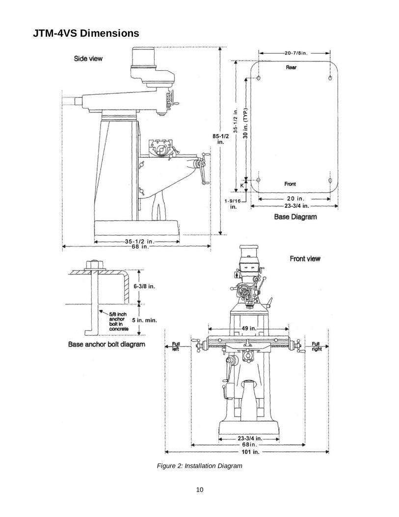
JTM-4VS Dimensions
Figure 2: Installation Diagram

11
JTM-4VS Overview and Terminology
Figure 3: Overview

12
Electrical Connections All electrical connections must
be made by a qualified electrician! Failure to comply may cause serious injury!
General Electrical Cautions This machine must be grounded in accordance with the National Electrical Code and local codes and ordinances. This work should be done by a qualified electrician. The machine must be grounded to protect the user from electrical shock.
Wire Sizes
For circuits which are far away from the electrical service box, the wire size must be increased in order to deliver ample voltage to the motor. To minimize power losses and to prevent motor overheating and burnout, the use of wire sizes for branch circuits or electrical extension cords according to the following table is recommended:
Conductor Length
AWG Number 230/460 Volt Lines 120 Volt Lines
0 – 50 Ft. No. 14 No. 14 50 – 100 Ft. No. 14 No. 12 Over 100 Ft. No. 12 No. 8
Figure 4
Confirm that power at the site matches power requirements of the mill before connecting to the power source.
The JTM-4VS has been pre-wired for 230 volt operation. To change from 230V to the other voltage offered, remove the junction box cover on the motor and change the wires according to the diagram found on the inside of the cover.
Before connecting to the power source, make sure that the switch is in the off position.
The mill must be properly grounded.
Check for proper spindle rotation in the high-speed range. The spindle should rotate clockwise when viewed from the top of the machine. If the spindle rotates counter-clockwise, disconnect from power and switch two of the three power leads.
Lubrication
Do not operate the mill before lubricating the machine fully. Failure to comply may cause damage to the machine. Refer to the Maintenance/Lubrication section and make sure the machine has been fully lubricated before operating.
Operating Instructions Operating Controls The lubrication system is a manually operated, one-shot system requiring operator intervention. The operator must lower the one-shot lever to lubricate the machine ways and ball screws. The one-shot lubrication system reservoir is located on the left side of the machine.
The position of the milling machine mill head can be set up to accommodate the work piece being machined. The mill head can be set up for angles to the left or right and for fore and aft angles. The mill head can also be rotated on its turret. The ram can be moved back and forth to reach work piece locations at the fore and aft extremes of worktable travel. Refer to the Adjustments section.
Motor Switch The Motor Switch is on the upper left-hand side of the mill head (Figure 5). The switch has three positions: FWD (forward), STOP, and REV (reverse).
Setting the switch to FWD will provide clockwise spindle rotation. Use FWD for normal, right-hand tooling.
FWD (clockwise) operation occurs only when the gearbox is in the low speed position. When the gearbox is in high-speed position, the motor switch must be in the REV position to provide right-hand or clockwise rotation. Refer to Figure 6 for a chart of required switch positions.
The motor switch controls a three-phase motor. The motor can be switched from FWD to REV and back with the motor running, and will reverse direction when the switch setting is changed. At higher speeds, this may put strain on the timing belt but there will be no damage to the motor or gear mechanism.
Figure 5

13
Figure 6
Variable Speed Control Change speed only while the spindle is turning.
The vari-speed handwheel (A, Figure 7) is used to control the spindle speed. The speeds for high and low speed ranges are displayed on the panel on the front of the mill head (B, Figure 7).
All speed changes must be made while the motor is running. Attempting speed changes without the motor running can result in damage to the drive mechanism.
Figure 7

14
Spindle Brake The spindle brake lever is located on the upper left side of the mill head (Figure 8). Pull lever downward to apply the brake. The spindle brake lever is used only after the motor switch has been set to OFF. The spindle will not stop with the motor running.
Figure 8
High-Neutral-Low Shift Lever The mill head can be driven directly (High Speed) or through the back gear (Low Speed) in the mill head. The selection is made by changing the position of the shift lever.
The shift lever is located at the lower right side of the mill head (Figure 9). The lever position closest to the operator is the High setting. The lever position away from the operator is the Low setting. The middle position is the Neutral setting.
Do not shift the High-Low Gear Lever while the motor is
running. Rotate the spindle by hand to facilitate changing lever positions.
Figure 9
Quill Power Feed Lever Do not use power feed at speeds above 3000 R.P.M.
It is recommended to disengage the power feed worm gear
whenever the power feed is not required. This avoids unnecessary wear on the worm gear.
Do not move the Quill Power Feed Lever unless the motor is
at a complete stop. When changing the lever position, do it gently. If the gear does not engage, jog the motor and allow it to stop before attempting to change.
The quill power feed lever is located on the right side of the mill head (Figure 10). It is used to engage and disengage the quill power feed mechanism.
The power feed is engaged by pulling out the knob and rotating the handle to a new locked position. When engaged, the power feed mechanism will drive the spindle upward or downward. The power feed mechanism will not drive the spindle when the handle is in the disengage position.
Figure 10
Feed Rate Lever The Feed Rate Lever (Figure 11) is used to set the per-revolution rate of the power feed mechanism. Three feed rates are available: 0.0015-inch, 0.003-inch, and 0.006-inch per revolution. The positions are shown on an indicator plate under the feed rate lever.
The rate is selected by pulling out the knob on the feed rate lever and moving the handle to the detent of the desired feed rate.
Note: The knob is spring loaded – pull out to rotate to new position.
Unlike other controls on the machine, the lever shifts into engagement more easily with the motor running, and the quill feed lever engaged.
Figure 11

15
Feed Trip Cam Lever The Feed Trip Cam Lever (A, Figure 12) is located on the left side of the head behind the Manual Fine Feed Handwheel (B, Figure 12). It engages the overload clutch on the pinion shaft when positioned to the left. The Feed Trip Cam Lever stays engaged until Quill Stop (C, Figure 15) comes in contact with Micrometer Adjusting Nut (A, Figure 15) forcing it to drop out automatically, or until it is released manually by engaging the lever to the right.
Figure 12
Feed Direction Control The Feed Direction Control (B, Figure 13) determines whether the power feed will move up, down, or not move at all. The position of the knob depends upon the direction of spindle rotation (see the Motor Switch section). The position of the control may be changed with the system stopped or running. If the control does not engage easily, move the fine feed handwheel (A, Figure 13) back and forth to aid engagement.
If the spindle is rotating clockwise, in is downfeed; out is upfeed. If the spindle rotation is counterclockwise, out is downfeed; in is upfeed. Neutral position is between the in and out position.
It is recommended that the Feed Direction Knob be left in the
neutral position when not in use.
Figure 13
Coarse Feed Handle The Coarse Feed Handle (A, Figure 14) is located on the right side of head. The Coarse Feed Handle is used for non-precision drilling operations and for moving the quill to a specific depth. A return spring will retract the spindle automatically once the handle is released.
Quill Lock Lever The Quill Lock Lever (B, Figure 14) is located on the right side of the head. Rotate the handle clockwise to lock the quill in a desired position. Rotate the handle counter-clockwise to release.
Figure 14
Micrometer Adjusting Nut The Micrometer Adjusting Nut (A, Figure 15) is located on the front of the head. Use for setting specific spindle depth. Secure with the lock nut (B, Figure 15).
Fine Feed Handwheel When the controls are set for the Fine feed using Handwheel position (see Figure 6), the Fine Feed Handwheel (A, Figure 13) can be used for manual fine feed control in either upward or downward direction of the quill.
Remove the Manual Fine Feed Handwheel when not in use.
Failure to comply may cause serious injury.

16
Depth Scale and Stop Referring to Figure 15:
The Depth Scale and Stop are used in drilling operations to set the depth of the drilled hole. The depth scale is located on the front of the mill head. The scale consists of a Micrometer Adjusting Nut (A), Lock Nut (B), Quill Stop (C), Quill Stop Screw (D), and Scale (E).
The Micrometer Adjusting Nut is set to the desired dimension and locked in place using the Lock Nut. The quill stop provides a positive stop for quill travel.
The graduations on the micrometer nut are in 0.001-inch increments. Adjustment of quill travel is made by rotating the micrometer nut.
Figure 15
Power Feed Operation The Feed Trip Adjustment sets the point at which the quill will reset during Power Feed.
Referring to Figure 17:
Be sure that the Manual Fine Feed Handwheel is removed.
Failure to comply may cause serious injury.
1. Loosen the Locknut (I). 2. With the Quill Feed Handle (J), advance the quill
to the point where the feed should stop. 3. Engage the Feed Trip Cam Lever (D) by pulling
away from head assembly. 4. Adjust Micrometer Adjusting Nut (H) against
Quill Stop (G). 5. Continue turning the Micrometer Adjusting Nut
(H) until the Feed Trip Cam Lever (D) trips. 6. Tighten the Locknut (I). 7. Ensure Quill Lock (K) is disengaged by rotating
counter-clockwise. 8. Start the spindle (A):
9. Select feed rate with the Variable Speed Control Handwheel (E).
10. Set the Feed Rate Lever (B) to the feed rate required for the tooling and material required.
11. Place the Quill Feed Engagement Lever (F) in the Engaged position.
12. Select feed direction by setting the Feed Direction Knob (C) position per the table:
Spindle Dir. Feed Dir. Knob Pos.
CW Down In Up Out
CCW Down Out Up In
Figure 16
13. Engage the Feed Trip Cam Lever (D) by pulling away from head assembly.
Note: Due to variables in tool diameter, coatings, coolant, and materials, no specific spindle speed or feed rate recommendations are provided. Use general shop manuals that have data applicable to the milling and drilling operations being performed. Or, contact the supplier of the tooling, coolant, and material for specific recommendations.
IMPORTANT: The power feed can be used for drills up to 3/8” in diameter (mild steel). Use manual feed for drills larger than 3/8”.
The overload clutch is factory set to hold up to 200 lbs. downfeed pressure on the quill (accommodates drills up to 3/8”). Do not attempt to adjust clutch pressure.
Figure 17

17
Draw Bar Operation - Changing Tooling 1. Using the wrench provided with the machine,
loosen the draw bar two or three turns (turn counterclockwise) using the draw bar hex (Figure 18).
Figure 18
2. Tap the top of the draw bar with a soft-faced hammer to loosen the collet from the taper.
3. Remove the tool from the collet.
4. Insert the tool you are going to use into the collet.
5. Tighten the draw bar firmly using the wrench provided with the machine. Turn the draw bar. The tool is now ready for use.
Clamping Work Piece to the Table 1. The worktable has 5/8-inch T-slots for clamping
the work piece to the table.
2. Set motor switch to STOP position.
3. Place the work piece on the table.
4. Clamp the work piece using the T-slot clamps, studs, and step blocks as required (Figure 19).
Figure 19
Adjustments Mill Head – Left/Right Adjustment
Make sure the machine base is secured to the floor before repositioning the mill head. The center of gravity can shift enough to cause the machine to tip over, resulting in serious injury to the operator and damage to the machine.
1. Loosen four large hex nuts that secure the mill head to the ram adapter (refer to Figure 20).
1/4 turn should be sufficient to allow the head to move.
NOTE: For angles greater than 10 degrees, use your free hand to support the mill head, taking some weight off the brass worm gears. Doing so will greatly lengthen the life of the worm gears.
Figure 20
2. Turn the worm nut (B, Figure 20) to tilt the head left or right as required. Use the scale on the ram adapter to set the desired angle.
Note: The scales on the ram adapter and for head rotation are guides only. Close tolerance work will require the use of a dial indicator to make sure the head is 90° to the table in the X and Y axis. Please note the table is fitted to be slightly higher in front, usually about 0.0005”.
Be sure to apply torque in two steps using a crossing pattern. Failure to do so could distort the face of the ram adapter.
3. Tighten the four hex nuts. Tighten in two steps using a calibrated torque wrench. Use a crossing pattern to tighten the nuts. Tighten initially to 25 foot-pounds.

18
4. Before applying final torque, check to make sure the mill head is perpendicular to the worktable.
5. Set up a dial indicator in a collet and secure using the draw bar (refer to Figure 22).
6. Put the spindle drive in neutral.
7. Set the dial indicator plunger on the worktable. Zero the indicator.
8. Rotate the spindle 180 degrees (when rotating, raise the dial indicator plunger by hand to prevent it from dropping into the table T-slots).
9. Read the dial indicator. The indicator should read zero. If not, loosen the four hex nuts and reposition the mill head.
10. Recheck perpendicularity using the dial indicator. Repeat the procedure above until the dial indicator reads zero in both positions.
Be sure to apply torque in two steps using a crossing pattern. Failure to do so could distort the face of the ram adapter.
11. Tighten the four hex nuts. Tighten in two steps using a calibrated torque wrench. Use a crossing pattern to tighten the nuts. Tighten initially to 25 foot-pounds, then tighten to a final torque of 50 foot-pounds.
Mill Head – Fore/Aft Adjustment 1. Setting the angle:
a. Loosen the three ram adapter clamp bolts on the ram (A, Figure 21). There is no need to loosen the bolts more than 1/2 turn to allow tilting.
Figure 21
b. Support the mill head with your free hand. Press upward on the spindle when changing the angle.
c. Turn the ram adapter worm nut (B, Figure 21) to tilt the head forward and backward. Use the scale on the ram adapter to locate the desired angle.
2. Returning to upright position:
a. When returning the mill head to its full upright position, be sure to support the head by upward pressure on the spindle as you turn the worm nut.
b. Check to make sure the mill head is perpen-dicular to the worktable.
c. Set up a dial indicator in a collet and secure using the draw bar (refer to Figure 22).
Figure 22
d. Put the spindle drive in neutral.
e. Set the dial indicator plunger on the worktable. Zero the indicator.
f. Rotate the spindle 180 degrees (when rotating, raise the dial indicator plunger by hand to prevent it from dropping into the table T-slots).
g. Read the dial indicator. The indicator should read zero. If not, loosen the four hex nuts and reposition the mill head.
h. Recheck perpendicularity using the dial indicator. Repeat the procedure above until the dial indicator reads zero in both positions.
i. When the indicator reads zero, tighten the ram adapter clamp bolts.

19
Positioning the Ram Positioning the Ram Fore and Aft 1. Loosen the two bolts (A, Figure 23) that lock the
ram to its ways.
Figure 23
2. Turn the lever (B, Figure 23) to move the ram on its ways.
3. When the desired position is reached, lock the bolts (A, Figure 23) securely.
Positioning the Ram on its Turret
Make sure the machine base is secured to the floor before repositioning the ram. The center of gravity can shift enough to cause the machine to tip over, resulting in serious injury to the operator and damage to the machine.
1. Loosen four turret lock bolts (C, Figure 23) that clamp the ram to the top of the base. 1/2 turn should be sufficient to allow the turret to move.
Note: Use gentle hand pressure to avoid rapid movement.
2. Turn the ram until the spindle is in the desired position. Use the scale on the turret for degree measurement.
3. Tighten the four turret lock bolts (C. Figure 23).
Gib Adjustment The table, saddle and knee are equipped with adjustable gibs. The gibs may require adjustment if unusual vibration is noted when the locking mechanisms are off, or if you experience unusual vibration when spindle speed, tooth pitch or depth of cut do not account for the vibration.
NOTE: When adjusting gibs, always start with the knee first; adjust the saddle second, and adjust the table last.
Figure 24
Adjustment of Knee Gib The knee gib adjustment screw (A, Figure 24) is located under the chip wiper at the rear of the knee where it contacts the column. Remove the way cover and the wiper to expose the gib adjustment screw. Tighten the screw until a slight drag is felt when turning the knee crank.
Adjustment of Saddle Gib The saddle gib adjustment screw is on the left front of the saddle (B, Figure 24). Tighten the screw until a slight drag is felt when turning the cross-feed crank.
Adjustment of Table Gib The table gib adjustment screw (C, Figure 24) is on the left-hand side, beneath the table. Tighten the screw until a slight drag is felt when turning the longitudinal table cranks.

20
Power Feed Trip Lever Mechanism Refer to Figure 25.
The power feed trip lever mechanism will need to be adjusted if worn or whenever any trip lever mechanism components are replaced.
1. Loosen the feed trip adjusting screw lock nut.
2. Loosen the adjusting screw until it is loose in the lever and no longer contacts the bottom of the feed trip plunger.
3. Using the coarse feed handle, move the quill to the bottom of its travel so the quill stop contacts the micrometer nut. Hold the quill on the stop.
4. Pull the feed handle out to engage the power feed system.
5. Turn the feed trip adjusting screw until the power feed disengages.
6. Tighten the feed trip adjusting screw.
7. Release the quill stop so you can engage the power feed mechanism using the power feed trip lever.
8. Using the coarse feed handle, pull the quill stop back into firm contact with the micrometer nut.
Figure 25
Note: The power feed should disengage when the quill stop pushes on the micrometer nut. If it does not disengage, repeat the adjustment steps above.
9. Engage the power feed and move the quill stop to the top of its travel. Make sure that the reverse trip mechanism also disengages the
power feed. If not, readjust the mechanism until positive disengagement occurs when the quill is at the top of its stroke.
10. Check for correct operation using the coarse feed handle. If operating correctly, start the drive motor and engage the power feed mechanism. Verify that the power feed lever correctly engages and disengages when driven by the drive motor.
Table Lead Screw Backlash Adjustment Refer to Figure 26.
The milling machine table is moved by a lead screw and nut for each machine axis. For proper operation, there must be clearance between the lead screw and the nut, which results in backlash. A second lead screw nut is provided to eliminate most of the backlash. The following procedures provide instructions for obtaining acceptable backlash.
Cross Feed Backlash Adjustment 1. Use the cross feed crank to move the table to the
extreme rear of its travel.
2. Remove the pleated way cover.
3. Open the two chip guards enough to expose the cross-feed adjustment nut (the nut that is toward the rear of the nut bracket is not adjustable – only the front nut is adjustable).
4. Loosen the two nut locking screws.
5. Turn the nut slightly to tighten it against the opposing nut.
6. Tighten the two nut locking screws.
7. Using the cross-feed crank, move the table to the middle position.
8. Set up a dial indicator to check cross-feed backlash. Gently move the cross feed crank back and forth while watching the dial indicator. Backlash should be between 0.003 inch and 0.005 inch.
9. If necessary, repeat the steps above to set backlash.
10. Install the pleated way cover.
Longitudinal Backlash Adjustment Refer to Figure 26.
1. Only one of the longitudinal lead screw nuts can be adjusted. The other nut is fixed. The left hand nut is typically adjustable. This can be determined by looking at the nut from the underside of the table.
2. Loosen the two nut locking screws.
3. Turn the nut slightly to tighten it against the opposing nut.

21
4. Tighten the two nut locking screws.
5. Using the longitudinal table crank, move the table to the middle position.
6. Set up a dial indicator to check longitudinal backlash. Gently move the crank back and forth while watching the dial indicator. The backlash should be between 0.003 inch and 0.005 inch.
If necessary, repeat the steps above to set backlash.
Figure 26

22
Maintenance Before any intervention on the machine, disconnect it from the electrical supply by
pulling out the plug or switching off the main switch! Failure to comply may cause serious injury.
Lubrication The milling machine is equipped with a “one-shot” lubrication system. The system lubricates the lead screws and ways. An oil cup and grease nipple on the mill head provide lubrication for the spindle bearings and back gear mechanism. Refer to Figures 28 and 29 for lubrication requirements and access points.
Key Description Recommended Lubricant Action
A Spindle bearing oil cup Mobil DTE Oil Light, or equivalent Service daily.
B One-shot lube system Mobil Vactra Oil #2, or equivalent Check oil daily – add if required. Pull lube handle every hour during operations.
C Knee leadscrew grease nipple Mobilith AW2, or equivalent Service once each week.
D Back gear grease nipple Mobilith AW1, or equivalent Service weekly when operating in back gear mode.
Figure 27: Lubrication Points
Figure 28
Figure 29
Periodic Maintenance Requirements During operation, periodically vacuum and brush chips and debris from machine.
Periodically operate knee and table lead screws through full range of movement to evenly distribute lubricant (particularly when applied using the “one-shot” system).
Periodically apply light machine oil to work table and other exposed metal surfaces to prevent rust or corrosion.
Periodically remove vent panels to check pulleys and belts for unusual wear or grooving. NOTE: Operators should vary speed occasionally to prevent formation of grooves on the pulley surfaces.

23
Replacement of Drive Motor Refer to Figure 30 and Head Assembly in the Parts section.
Figure 30
1. Operate spindle at its highest speed.
Disconnect electrical power to the machine before performing any maintenance.
2. Disconnect electrical power. Remove junction box cover and disconnect wiring. Tag wires to identify leads for reinstallation.
3. Remove vent covers on both sides of head to provide access to the vari-speed belt and pulleys.
4. Remove the lower cover plate under the motor pulley (at the rear of the cover) by removing three cap screws.
5. Remove the four screws that attach the motor.
6. Connect a lifting sling to support and lift the motor during removal. Ease the motor up and forward on the housing.
7. Tilt the motor slightly toward the rear to slacken the vari-speed belt. Remove the vari-speed belt from the motor pulley.
8. Remove the belt; lift the motor clear of the housing.
Do not attempt to remove the screw from the end of the motor shaft without use of a hydraulic press. Failure to comply may cause serious injury.
The screw retains the underlying spring stop washer, which is under spring tension. Serious injury can result if the spring tension is not gradually released using the hydraulic press. Proceed as follows.
9. Support the drive motor in a hydraulic press. Move the hydraulic ram into contact with the spring stop washer (ref. 9). Remove the screw (ref. 107) from the end of the motor shaft.
10. Slowly release pressure on hydraulic ram until the spring (ref. 8) is fully extended.
11. Remove the lengthening shaft (ref. 106), spring stop washer (ref. 9), spring (ref. 8) and outermost pulley (ref. 5) from the motor shaft.
12. Loosen set screw (ref. 3) on innermost pulley (ref. 2). Remove the pulley (ref. 2) and drive key (ref. 7) from the motor shaft.
13. Install drive key (ref. 7) and pulley (ref. 2) on shaft of replacement motor. Tighten set screw (ref. 3) on pulley.
14. Support the drive motor in a hydraulic press. Place the outermost pulley (ref. 5) on the motor shaft.
15. Install the spring (ref. 8), spring stop washer (ref. 9), and lengthening shaft (ref. 106) on the motor shaft.
16. Move the hydraulic ram into contact with the spring stop washer (ref. 9). Compress the spring (ref. 8) and install the lengthening shaft (ref. 106) on the motor shaft. Install and tighten the attaching screw (ref. 107) in the end of the motor shaft.
17. Using an overhead hoist, lift the replacement motor into position.
18. Tilt the motor slightly toward the rear and install the vari-speed belt on the motor pulleys.
19. Install the four motor attaching screws.
20. Install lower cover plate.
21. Connect electrical wiring to motor junction box.
22. Start the drive motor. Operate the spindle throughout its speed range to check operation.
23. Install vent covers on mill head.
Figure 31

24
Replacement of Vari-Speed Belt Refer to Figures 31 and 32, and Head Assembly in the Parts section.
Disconnect electrical power to the machine before performing any maintenance.
1. Remove drive motor (refer to the Replacement of Drive Motor section).
2. Remove Quill Top Cover by removing three cap screws (Figure 31).
3. Remove six cap screws and remove the upper housing (Figure 32).
4. Remove the vari-speed belt (ref. 4).
5. Install the new vari-speed belt (ref. 4) on the driven hub (ref. 44).
6. Install drive motor (refer to the Replacement of Drive Motor section).
Figure 32
Replacement of Brake Shoes, Springs and/or Timing Belt
Disconnect electrical power to the machine before performing any maintenance.
1. Remove drive motor (refer to the Replacement of Drive Motor section).
2. Remove vari-speed belt and upper housing (refer to the Replacement of Vari-Speed Belt section).
3. Remove screws from lower housing cover (ref. 50).
4. Loosen the setscrew (ref. 3) securing the brake pivot finger stud (ref. 58) in the lower housing cover (ref. 50).
5. Move the pivot finger stud (ref. 58) inward enough to remove the snap ring (ref. 60).
Figure 33
6. Pull the pivot finger stud (ref. 58) out of the lower housing cover (ref. 50) and the brake pivot fingers (ref. 59).
7. Before removing, note the orientation of the brake pivot fingers (ref. 59) for correct positioning for re-assembly. Remove the pivot fingers.
If replacing the brake components only, skip Steps 8 and 9 and go to Step 10.
To replace the timing belt:
8. Remove lower housing cover and pulley.
9. Replace belt (ref 63).
To replace the brake components:
10. Using a soft-faced mallet, tap upward to separate the lower housing cover (ref. 50) and the brake assembly (ref. 47) from the bearing (ref. 43).
11. Remove the brake shoes (ref. 47) and springs (ref. 49). Install the replacement brake shoes and springs.
For all:
12. Position the brake pivot fingers (ref. 59) as noted during removal. Install the pivot finger stud (ref. 58) through the lower housing cover (ref. 50) and into the brake pivot fingers (ref. 59). Install the snap ring (ref. 60) on the pivot finger stud (ref. 58).
13. Tighten the setscrew (ref. 3) to secure the pivot finger stud (ref. 58).
14. Install the brake assembly (ref. 47) on the lower housing cover (ref. 50).
15. Secure the lower housing cover (ref. 50) with four screws.
16. Install timing belt and upper housing.
17. Install vari-speed belt (refer to the Replacement of Vari-Speed Belt section).
18. Install drive motor (refer to the Replacement of Drive Motor section).

25
Replacement of Quill Feed Clock Spring Refer to the Spindle Assembly in the Parts section.
Disconnect electrical power to the machine before performing any maintenance.
1. Remove the coarse feed handle.
2. Remove the screw, hub, and key from the coarse feed shaft (ref. 172, 175, and 171).
3. Remove six screws (Ref. 1) and allow the clock spring (ref. 178) to slowly unwind.
4. Remove feed handle hub sleeve (ref. 176).
5. Lift the end of the spring (ref. 178) from the pin (ref. 168) on the pinion shaft (ref. 166).
6. Remove the spring (ref. 178) from the spring cover (ref. 177).
7. Install the replacement spring (ref. 178) in the spring cover (ref 177).
8. Install end of spring (ref. 178) over the pin (ref. 168) on pinion shaft (ref. 166).
9. Install pin (ref. 168) in feed handle hub sleeve (ref. 176) on other end of spring (ref. 178).
10. Turn the spring cover (ref. 177) to wind the spring (ref. 178). Turn the spring cover (ref. 177) until the desired tension is achieved. Hold the spring cover (ref. 177) in position and secure with six screws (ref. 1).
11. Install the key, hub, and screw (ref. 171, 175, and 172) onto the feed shaft (ref. 166).
Replacement Parts Replacement parts are listed on the following pages. To order parts or reach our service department, call 1-800-274-6848, Monday through Friday (see our website for business hours, www.waltermeier.com). Having the Model Number and Serial Number of your machine available when you call will allow us to serve you quickly and accurately.

26
Head Assembly
27
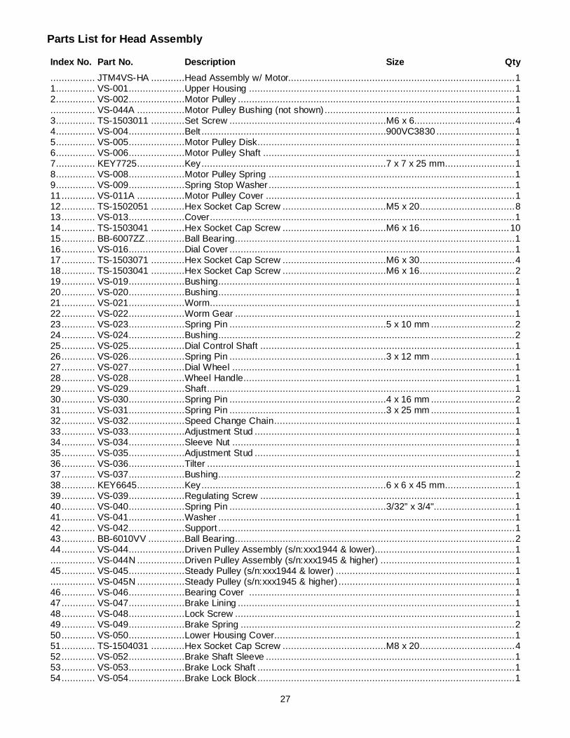
Parts List for Head Assembly
Index No. Part No. Description Size Qty ................ JTM4VS-HA ............Head Assembly w/ Motor................................................................................. 1 1 .............. VS-001....................Upper Housing ............................................................................................... 1 2 .............. VS-002....................Motor Pulley ................................................................................................... 1 ................ VS-044A .................Motor Pulley Bushing (not shown) .................................................................... 1 3 .............. TS-1503011 ............Set Screw ........................................................M6 x 6.................................... 4 4 .............. VS-004....................Belt ..................................................................900VC3830 ............................ 1 5 .............. VS-005....................Motor Pulley Disk............................................................................................ 1 6 .............. VS-006....................Motor Pulley Shaft .......................................................................................... 1 7 .............. KEY7725.................Key ..................................................................7 x 7 x 25 mm......................... 1 8 .............. VS-008....................Motor Pulley Spring ........................................................................................ 1 9 .............. VS-009....................Spring Stop Washer ........................................................................................ 1 11 ............ VS-011A .................Motor Pulley Cover ......................................................................................... 1 12 ............ TS-1502051 ............Hex Socket Cap Screw .....................................M5 x 20 .................................. 8 13 ............ VS-013....................Cover ............................................................................................................. 1 14 ............ TS-1503041 ............Hex Socket Cap Screw .....................................M6 x 16 ................................ 10 15 ............ BB-6007ZZ ..............Ball Bearing.................................................................................................... 1 16 ............ VS-016....................Dial Cover ...................................................................................................... 1 17 ............ TS-1503071 ............Hex Socket Cap Screw .....................................M6 x 30 .................................. 4 18 ............ TS-1503041 ............Hex Socket Cap Screw .....................................M6 x 16 .................................. 2 19 ............ VS-019....................Bushing.......................................................................................................... 1 20 ............ VS-020....................Bushing.......................................................................................................... 1 21 ............ VS-021....................Worm ............................................................................................................. 1 22 ............ VS-022....................Worm Gear .................................................................................................... 1 23 ............ VS-023....................Spring Pin ........................................................5 x 10 mm .............................. 2 24 ............ VS-024....................Bushing.......................................................................................................... 2 25 ............ VS-025....................Dial Control Shaft ........................................................................................... 1 26 ............ VS-026....................Spring Pin ........................................................3 x 12 mm .............................. 1 27 ............ VS-027....................Dial Wheel ..................................................................................................... 1 28 ............ VS-028....................Wheel Handle................................................................................................. 1 29 ............ VS-029....................Shaft .............................................................................................................. 1 30 ............ VS-030....................Spring Pin ........................................................4 x 16 mm .............................. 2 31 ............ VS-031....................Spring Pin ........................................................3 x 25 mm .............................. 1 32 ............ VS-032....................Speed Change Chain ...................................................................................... 1 33 ............ VS-033....................Adjustment Stud ............................................................................................. 1 34 ............ VS-034....................Sleeve Nut ..................................................................................................... 1 35 ............ VS-035....................Adjustment Stud ............................................................................................. 1 36 ............ VS-036....................Tilter .............................................................................................................. 1 37 ............ VS-037....................Bushing.......................................................................................................... 2 38 ............ KEY6645.................Key ..................................................................6 x 6 x 45 mm......................... 1 39 ............ VS-039....................Regulating Screw ........................................................................................... 1 40 ............ VS-040....................Spring Pin ........................................................3/32” x 3/4"............................. 1 41 ............ VS-041....................Washer .......................................................................................................... 1 42 ............ VS-042....................Support .......................................................................................................... 1 43 ............ BB-6010VV .............Ball Bearing.................................................................................................... 2 44 ............ VS-044....................Driven Pulley Assembly (s/n:xxx1944 & lower).................................................. 1 ................ VS-044N .................Driven Pulley Assembly (s/n:xxx1945 & higher) ................................................ 1 45 ............ VS-045....................Steady Pulley (s/n:xxx1944 & lower) ................................................................ 1 ................ VS-045N .................Steady Pulley (s/n:xxx1945 & higher) ............................................................... 1 46 ............ VS-046....................Bearing Cover ............................................................................................... 1 47 ............ VS-047....................Brake Lining ................................................................................................... 1 48 ............ VS-048....................Lock Screw .................................................................................................... 1 49 ............ VS-049....................Brake Spring .................................................................................................. 2 50 ............ VS-050....................Lower Housing Cover...................................................................................... 1 51 ............ TS-1504031 ............Hex Socket Cap Screw .....................................M8 x 20 .................................. 4 52 ............ VS-052....................Brake Shaft Sleeve ......................................................................................... 1 53 ............ VS-053....................Brake Lock Shaft ............................................................................................ 1 54 ............ VS-054....................Brake Lock Block ............................................................................................ 1

28
55 ............ TS-1503061 ............Hex Socket Cap Screw .....................................M6 x 25 .................................. 1 56 ............ VS-056....................Brake Lock Handle ......................................................................................... 1 57 ............ VS-057....................Plastic Ball ..................................................................................................... 2 58 ............ VS-058....................Brake Finger Pivot Stud .................................................................................. 1 59 ............ VS-059....................Brake Stud ..................................................................................................... 2 60 ............ VS-060....................Snap Ring ........................................................S-8 ........................................ 2 61 ............ TS-0561072 ............Nut ..................................................................5/8”-18 UNF ........................... 1 62 ............ VS-062....................Timing Belt Pulley ........................................................................................... 1 63 ............ VB-225L100 ............Timing Belt .......................................................225L100................................. 1 64 ............ VS-064....................Bearing Retainer............................................................................................. 1 65 ............ BB-6203ZZ ..............Ball Bearing.................................................................................................... 2 66 ............ VS-066....................Bull Gear ........................................................................................................ 1 67 ............ VS-067....................Counter Shaft ................................................................................................. 1 68 ............ VS-068....................Key ..................................................................5 x 5 x 15 mm......................... 1 69 ............ VS-069....................Key ..................................................................5 x 5 x 18 mm......................... 1 70 ............ VS-070....................Spindle Pulley Hub ......................................................................................... 1 71 ............ VS-071....................Key ..................................................................8 x 7 x 24 mm......................... 1 72 ............ VS-072....................Key ..................................................................8 x 7 x 12 mm......................... 1 73 ............ VS-073....................Spindle Gear Hub ........................................................................................... 1 74 ............ VS-074....................Spindle Gear Assembly ................................................................................... 1 75 ............ VS-075....................Rack Cup ....................................................................................................... 1 76 ............ VS-076....................Washer .......................................................................................................... 1 77 ............ BB-6908ZZ ..............Ball Bearing.................................................................................................... 2 78 ............ VS-078....................Bearing Washer .............................................................................................. 1 79 ............ VS-079....................Bearing Washer .............................................................................................. 1 80 ............ VS-080....................Snap Ring ...................................................................................................... 1 81 ............ VS-081....................Nut ................................................................................................................ 1 82 ............ VS-082....................Lower Housing ............................................................................................... 1 83 ............ VS-083....................Fixed Clutch Bracket ....................................................................................... 1 84 ............ VS-084....................Spring ............................................................................................................ 1 85 ............ VS-085....................Stud ............................................................................................................... 3 86 ............ TS-1506021 ............Hex Socket Cap Screw .....................................M12 x 25 ................................ 3 87 ............ VS-087....................Gear Shift Pinion ............................................................................................ 1 88 ............ VS-088....................Pin ................................................................................................................. 1 89 ............ VS-089....................Detent Plate ................................................................................................... 1 90 ............ VS-090....................Detent Washer ............................................................................................... 1 91 ............ VS-091....................Spring ............................................................................................................ 1 92 ............ VS-092....................Pinion Block ................................................................................................... 1 93 ............ TS-1503011 ............Hex Socket Cap Screw .....................................M5 x 14 .................................. 2 94 ............ VS-094....................Pinion Crank .................................................................................................. 1 95 ............ VS-095....................Cap Nut ......................................................................................................... 1 96 ............ TS-0561031 ............Hex Nut............................................................3/8” ........................................ 1 97 ............ VS-097....................Snap Ring ...................................................................................................... 1 98 ............ VS-098....................Wave Washer................................................................................................. 1 99 ............ VS-099....................Plastic Ball ..................................................................................................... 1 100 .......... VS-100....................Snap Ring ...................................................................................................... 1 101 .......... VS-101B .................Cover ............................................................................................................. 2 102 .......... VS-102....................Spring Shaft ................................................................................................... 3 103 .......... VS-103....................Washer .......................................................................................................... 1 104 .......... VS-104....................Copper Washer .............................................................................................. 2 105 .......... VS-105....................Screw ..............................................................1/4" x 3/8”............................... 8 106 .......... VS-107....................Shaft .............................................................................................................. 1 107 .......... TS-1504061 ............Hex Socket Cap Screw .....................................M8 x 30 .................................. 1 109 .......... VS-109....................Lock Washer .................................................................................................. 1 110 .......... TS-1540041 ............Hex Nut............................................................M6 ......................................... 1 111 .......... TS-0209051 ............Hex Socket Cap Screw .....................................3/8” x 1” ................................. 4 112 .......... VS-000....................Motor ...............................................................3HP 3PH ................................ 1 ................ JTM4VS-112 ...........Motor ...............................................................2HP 1PH ................................ 1 113 .......... VS-113....................Oval Head Screw..............................................1/8” x 1/4"............................... 4 114 .......... JTM1-001VS ...........Draw Bar ........................................................................................................ 1 115 .......... JTM4VS-A002B .......Draw Bar Washer ........................................................................................... 1

29
116 .......... VS-116....................Key ................................................................................................................ 1 117 .......... VS-117....................Oval Head Screw..............................................3/16” x 1/2” ............................. 1 118 .......... VS-007....................Snap Ring ...................................................................................................... 4 119 .......... VS-005A .................Plastic Sleeve................................................................................................. 2 120 .......... VS-120....................Key ..................................................................6 x 4 x 32 mm......................... 2 121 .......... BB-6206ZZ ..............Ball Bearing......................................................6206ZZ .................................. 1 ................ VS-000A .................Forward-Reverse Switch, 3 Phase (not shown) ................................................. 1 ................ JTM2-598CP ...........Forward-Reverse Switch, 1 Phase (not shown) ................................................. 1 ................ JTM1-598D .............Switch Box (not shown) ................................................................................... 1 ................ JTM1-598B..............Switch Knob (not shown) ................................................................................. 1 ................ LK-041B ..................Switch Bracket (not shown) ............................................................................. 1

30
Spindle Assembly

31
Parts List for Spindle Assembly
Index No. Part No. Description Size Qty 1 .............. TS-1533042 ............Screw ..............................................................M5 x 10 .................................. 6 2 .............. HA-002 ...................Bevel Pinion Washer....................................................................................... 1 3 .............. LA-166A ..................Feed Gear...................................................................................................... 1 4 .............. LA-161 ....................Shaft Sleeve ................................................................................................... 1 5 .............. LA-162 ....................Worm Cradle Bushing ..................................................................................... 1 6 .............. TS-1523011 ............Set Screw ........................................................M6 x 6.................................... 9 7 .............. LA-163 ....................Worm Gear Spacer ......................................................................................... 1 8 .............. LA-164 ....................Feed Drive Worm Gear ................................................................................... 1 9 .............. LA-165 ....................Worm Gear Shaft............................................................................................ 1 10 ............ HA-010 ...................Worm Shaft Key ...............................................3 x 3 x 8 mm........................... 1 11 ............ LA-166A ..................Key ..................................................................3 x 3 x 20 mm......................... 1 12 ............ HA-012 ...................Locknut ............................................................M6 x 16 .................................. 1 13 ............ LA-166A ..................Washer .......................................................................................................... 1 14 ............ HA-014 ...................Cluster Gear Key ..............................................3 x 3 x 8.5 mm ........................ 1 15 ............ LA-154 ....................Feed Reverse Bevel Gear ............................................................................... 1 16 ............ LA-167 ....................Feed Engage Pin ............................................................................................ 1 17 ............ LA-166 ....................Worm Gear Cradle.......................................................................................... 1 18 ............ LA-033 ....................Worm Gear Throw-Out .................................................................................... 1 19 ............ LA-002 ....................Shift Sleeve .................................................................................................... 1 20 ............ LA-004 ....................Plunger .......................................................................................................... 2 21 ............ LA-005 ....................Spring ............................................................................................................ 3 22 ............ HA-022 ...................Spring Pin ........................................................3 x 22 mm .............................. 2 23 ............ LA-003 ....................Shift Crank ..................................................................................................... 2 24 ............ LA-006 ....................Plastic Ball ..................................................................................................... 3 27 ............ LA-147 ....................Upper Bushing................................................................................................ 1 28 ............ LA-144 ....................Cluster Gear Assembly ................................................................................... 1 29 ............ HA-029 ...................Cluster Gear Key ..............................................3 x 3 x 45 mm......................... 1 31 ............ LA-143 ....................Cluster Gear Shaft .......................................................................................... 1 32 ............ HA-032 ...................Snap Ring ...................................................................................................... 2 33 ............ LA-142 ....................Bevel Gear Bushing ........................................................................................ 1 34 ............ LA-141 ....................Thrust Spacer................................................................................................. 1 36 ............ LA-156 ....................Feed Drive Gear ............................................................................................. 1 37 ............ LA-166A ..................Key ..................................................................3 x 3 x 10 mm......................... 1 40 ............ LA-157 ....................Feed Drive Gear ............................................................................................. 1 41 ............ HA-041 ...................Needle Bearing............................................................................................... 1 42 ............ LA-168 ....................Bushing.......................................................................................................... 1 43 ............ LA-139 ....................Worm ............................................................................................................. 1 44 ............ LA-138 ....................Feed Worm Shaft Bushing .............................................................................. 1 47 ............ LA-137 ....................Bevel Gear Thrust Spacer ............................................................................... 1 48 ............ LA-134 ....................Bushing.......................................................................................................... 2 49 ............ LA-135 ....................Feed Reverse Bevel Gear ............................................................................... 2 50 ............ LA-136 ....................Feed Reverse Clutch ...................................................................................... 1 55 ............ LA-132 ....................Reverse Clutch Rod ........................................................................................ 1 56 ............ HA-056 ...................Spring Pin ........................................................3 x 20 mm .............................. 1 57 ............ LA-133 ....................Feed Worm Shaft ............................................. ............................................. 1 59 ............ HA-059 ...................Spring Pin ........................................................3 x 12 mm .............................. 2 60 ............ LA-150 ....................Feed Shift Rod ............................................................................................... 1 61 ............ TS-1522031 ............Set Screw ........................................................M5 x 10 .................................. 1 62 ............ HA-062 ...................Key ..................................................................3 x 3 x 15 mm......................... 1 63 ............ LA-149 ....................Feed Gear Shift Fork ...................................................................................... 1 64 ............ LA-151 ....................Cluster Gear Shift Crank ................................................................................. 1 66 ............ LA-148 ....................Cluster Gear Cover ......................................................................................... 1 67 ............ TS-1504011 ............Hex Socket Cap Screw .....................................M8 x 10 .................................. 4 73 ............ TS-1502081 ............Hex Socket Cap Screw .....................................M5 x 35 .................................. 2 74 ............ LA-081 ....................Clutch Ring Pin............................................................................................... 2 75 ............ LA-080 ....................Clutch Ring .................................................................................................... 1 76 ............ TS-1524011 ............Set Screw ........................................................M8 x 8.................................... 1

32
78 ............ LA-082 ....................Overload Clutch Lockout ................................................................................. 1 79 ............ LA-083 ....................Safety Clutch Spring ....................................................................................... 1 80 ............ LA-084 ....................Overload Clutch .............................................................................................. 1 81 ............ LA-085 ....................Overload Clutch Sleeve................................................................................... 1 82 ............ LA-090 ....................Key ................................................................................................................ 1 83 ............ TS-1532052 ............Pan Head Machine Screw .................................M4 x 16 .................................. 3 85 ............ TS-1523031 ............Set Screw ........................................................M6 x 10 .................................. 2 88 ............ LA-169 ....................Spring ............................................................................................................ 1 89 ............ LA-089 ....................Spring Plunger................................................................................................ 1 90 ............ LA-123 ....................Pinion Shaft Bushing....................................................................................... 1 91 ............ LA-122 ....................Spacer ........................................................................................................... 1 92 ............ LA-087 ....................Overload Clutch Worm Gear............................................................................ 1 93 ............ LA-086 ....................Overload Clutch Ring ...................................................................................... 1 94 ............ HA-094 ...................Snap Ring ...................................................................................................... 1 96 ............ LA-079 ....................Trip Lever....................................................................................................... 1 97 ............ LA-078 ....................Washer .......................................................................................................... 1 98 ............ HA-098 ...................Snap Ring ...................................................................................................... 1 99 ............ LA-076 ....................Clutch Arm Cover ........................................................................................... 1 100 .......... TS-1523051 ............Set Screw ........................................................M6 x 10 .................................. 1 101 .......... HA-101 ...................Locknut .......................................................................................................... 1 102 .......... LA-077 ....................Pin ................................................................................................................. 3 103 .......... LA-091 ....................Cam Rod........................................................................................................ 1 104 .......... LA-100 ....................Trip Handle .................................................................................................... 1 106 .......... LA-092 ....................Feed Trip Bracket ........................................................................................... 1 107 .......... TS-1503051 ............Hex Socket Cap Screw .....................................M6 x 20 .................................. 2 109 .......... HA-109 ...................Key ..................................................................3 x 3 x10 mm.......................... 1 110 .......... LA-130 ....................Feed Reverse Knob Stud ................................................................................ 1 111 .......... LA-131 ....................Reverse Knob ................................................................................................ 1 112 .......... HA-112 ...................Snap Ring ...................................................................................................... 1 113 .......... LA-129 ....................Handwheel Clutch........................................................................................... 1 114 .......... SB-3/16 ...................Steel Ball..........................................................3/16” ...................................... 2 115 .......... HA-115 ...................Spring ............................................................................................................ 2 117 .......... HA-117 ...................Spring Pin ...................................................................................................... 1 118 .......... LA-093 ....................Cam Rod Sleeve Assembly ............................................................................. 1 121 .......... LA-095 ....................Trip Plunger ................................................................................................... 1 123 .......... LA-121 ....................Bushing.......................................................................................................... 1 124 .......... LA-097 ....................Feed Trip Plunger ........................................................................................... 1 125 .......... LA-126 ....................Handwheel ..................................................................................................... 1 126 .......... LA-125 ....................Handle ........................................................................................................... 1 127 .......... LA-050A ..................Spindle .......................................................................................................... 1 128 .......... LA-060 ....................Quill Skirt ....................................................................................................... 1 129 .......... LA-048 ....................Lock Nut ........................................................................................................ 1 131 .......... BB-6206ZZ ..............Ball Bearing.................................................................................................... 1 133 .......... LA-051 ....................Nose Piece..................................................................................................... 1 134 .......... LA-052 ....................Spindle Shield ................................................................................................ 1 135 .......... BB-7207C ...............Ball Bearing.................................................................................................... 2 136 .......... LA-054 ....................Bearing Spacer (large) .................................................................................... 1 137 .......... LA-053 ....................Bearing Spacer (small) .................................................................................... 1 140 .......... LA-172 ....................Set Screw ...................................................................................................... 1 142 .......... LA-058 ....................Quill ............................................................................................................... 1 143 .......... TS-154021 ..............Hex Nut............................................................M4 ......................................... 1 144 .......... TS-1521071 ............Set Screw ........................................................M4 x 20 .................................. 1 145 .......... LA-098 ....................Feed Trip Lever .............................................................................................. 1 146 .......... LA-099 ....................Trip Lever Pin ................................................................................................. 1 148 .......... LA-111 ....................Quill Lock Sleeve ............................................................................................ 1 149 .......... LA-109 ....................Lock Handle ................................................................................................... 1 150 .......... HA-150 ...................Screw ..............................................................M5 x 10 .................................. 2 151 .......... LA-057 ....................Felt Washer.................................................................................................... 1 153 .......... LA-110 ....................Quill Lock Sleeve ............................................................................................ 1 155 .......... LA-043 ....................T-Bolt Assembly ............................................................................................. 4 156 .......... LA-046 ....................Spacer ........................................................................................................... 4

33
157 .......... LA-040 ....................Lock Nut ........................................................................................................ 4 158 .......... HA-158 ...................Screw ..............................................................M4 x 5.................................... 2 159 .......... LA-118 ....................Micrometer Scale............................................................................................ 1 161 .......... LA-115 ....................Quill Micro-Stop Nut ........................................................................................ 1 162 .......... LA-116 ....................Micrometer Nut ............................................................................................... 1 163 .......... LA-117 ....................Quill Stop Knob .............................................................................................. 1 164 .......... LA-112 ....................Quill Micro-Screw ........................................................................................... 1 165 .......... LA-165A ..................Screw ..............................................................3/8”-24UNF x 3/4” ................... 1 166 .......... LA-101 ....................Quill Pinion Shaft ............................................................................................ 1 168 .......... LA-101A ..................Pin ................................................................................................................. 1 171 .......... HA-171 ...................Key ................................................................................................................ 2 172 .......... LA-107 ....................Pinion Shaft Hub............................................................................................. 1 173 .......... TS-0270021 ............Set Screw ........................................................5/16” x 1/4"............................. 1 175 .......... LA-106 ....................Hub ............................................................................................................... 1 176 .......... LA-104 ....................Hub Sleeve .................................................................................................... 1 177 .......... LA-103 ....................Spring Cover .................................................................................................. 1 178 .......... LA-102 ....................Clock Spring ................................................................................................... 1 ................ LA-102/3 .................Clock Spring Assembly ................................................................................... 1 179 .......... TS-0680061 ............Washer ............................................................1/2” ........................................ 1 181 .......... TS-1523011 ............Set Screw ........................................................M6 x 6.................................... 2 183 .......... LA-113 ....................Lever ............................................................................................................. 1 184 .......... LA-114 ....................Plunger .......................................................................................................... 1 185 .......... LA-124 ....................Screw ............................................................................................................ 1 186 .......... LA-018 ....................Worm Gear .................................................................................................... 1 188 .......... LA-173 ....................Set Screw ...................................................................................................... 1 189 .......... LA-019 ....................Worm Shaft .................................................................................................... 1 190 .......... LA-105 ....................Handle ........................................................................................................... 1 191 .......... LB-017 ....................Plastic Ball ..................................................................................................... 1 192 .......... LA-016 ....................Quill Housing .................................................................................................. 1 193 .......... HA-193 ...................Spring ..............................................................10 x 20 mm ............................ 1 194 .......... RINS30 ...................Snap Ring ...................................................................................................... 1 195 .......... HB1291 ...................Lock Washer .................................................................................................. 1 196 .......... TS-1524011 ............Set Screw ........................................................M8 x 8.................................... 1 197 .......... TS-0561031 ............Hex Nut............................................................3/8” ........................................ 1

34
Base Assembly
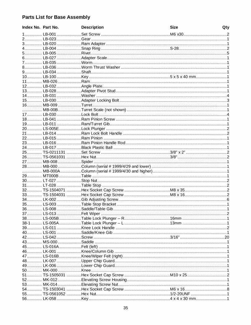
35
Parts List for Base Assembly
Index No. Part No. Description Size Qty 1 .............. LB-001 ....................Set Screw ........................................................M6 x30................................... 2 2 .............. LB-023 ....................Gear .............................................................................................................. 1 3 .............. LB-020 ....................Ram Adapter .................................................................................................. 1 4 .............. LB-004 ....................Snap Ring ........................................................S-28....................................... 2 5 .............. LB-005 ....................Rivet .............................................................................................................. 5 6 .............. LB-027 ....................Adapter Scale................................................................................................. 1 7 .............. LB-035 ....................Worm ............................................................................................................. 1 8 .............. LB-036 ....................Worm Thrust Washer ...................................................................................... 1 9 .............. LB-034 ....................Shaft .............................................................................................................. 1 10 ............ LB-100 ....................Key ..................................................................5 x 5 x 40 mm......................... 1 11 ............ MB-026 ...................Ram............................................................................................................... 1 12 ............ LB-032 ....................Angle Plate..................................................................................................... 1 13 ............ LB-028 ....................Adapter Pivot Stud .......................................................................................... 1 14 ............ LB-031 ....................Washer .......................................................................................................... 4 15 ............ LB-030 ....................Adapter Locking Bolt ....................................................................................... 3 16 ............ MB-009 ...................Turret ............................................................................................................. 1 ................ MB-00B ...................Turret Scale (not shown) ................................................................................. 1 17 ............ LB-030 ....................Lock Bolt ........................................................................................................ 4 18 ............ LB-041 ....................Ram Pinion Screw .......................................................................................... 1 19 ............ LB-011 ....................Ram/Turret Gib............................................................................................... 1 20 ............ LS-005E ..................Lock Plunger .................................................................................................. 2 21 ............ LB-014 ....................Ram Lock Bolt Handle .................................................................................... 2 22 ............ LB-015 ....................Ram Pinion .................................................................................................... 1 23 ............ LB-016 ....................Ram Pinion Handle Rod .................................................................................. 1 24 ............ LB-017 ....................Black Plastic Ball ............................................................................................ 1 25 ............ TS-0211131 ............Set Screw ........................................................3/8” x 2” ................................. 2 26 ............ TS-0561031 ............Hex Nut............................................................3/8” ........................................ 2 27 ............ MB-008 ...................Spider ............................................................................................................ 1 28 ............ MB-000 ...................Column (serial # 1999/4/29 and lower) ............................................................. 1 ................ MB-000A .................Column (serial # 1999/4/30 and higher) ............................................................ 1 29 ............ MT000B ..................Table ............................................................................................................. 1 30 ............ LT-027 ....................Stop Nut......................................................................................................... 2 31 ............ LT-028 ....................Table Stop ..................................................................................................... 2 32 ............ TS-1504071 ............Hex Socket Cap Screw .....................................M8 x 35 .................................. 2 33 ............ TS-1504031 ............Hex Socket Cap Screw .....................................M8 x 16 .................................. 2 34 ............ LK-002 ....................Gib Adjusting Screw........................................................................................ 6 35 ............ LS-003 ....................Table Stop Bracket ......................................................................................... 1 36 ............ LS-008 ....................Saddle/Table Gib ............................................................................................ 1 37 ............ LS-013 ....................Felt Wiper ...................................................................................................... 2 38 ............ LS-005B ..................Table Lock Plunger – R .....................................16mm .................................... 1 38-1 ......... LS-005A ..................Table Lock Plunger – L .....................................13mm .................................... 1 39 ............ LS-011 ....................Knee Lock Handle .......................................................................................... 2 40 ............ LS-001 ....................Saddle/Knee Gib ............................................................................................ 1 42 ............ LS-042 ....................Screw ..............................................................3/16” .................................... 20 43 ............ MS-000 ...................Saddle ........................................................................................................... 1 45 ............ LS-016A ..................Felt (left) ........................................................................................................ 1 46 ............ LK-001 ....................Knee/Column Gib ........................................................................................... 1 47 ............ LS-016B ..................Knee/Wiper Felt (right) .................................................................................... 1 48 ............ LK-007 ....................Upper Chip Guard........................................................................................... 1 49 ............ LK-006 ....................Lower Chip Guard........................................................................................... 1 50 ............ MK-000 ...................Knee .............................................................................................................. 1 51 ............ TS-1505031 ............Hex Socket Cap Screw .....................................M10 x 25 ................................ 2 52 ............ MK-012 ...................Elevating Screw Housing................................................................................. 1 53 ............ MK-014 ...................Elevating Screw Nut........................................................................................ 1 54 ............ TS-1503041 ............Hex Socket Cap Screw .....................................M6 x 16 .................................. 8 55 ............ TS-0561052 ............Hex Nut............................................................1/2-20UNF ............................. 1 56 ............ LK-058 ....................Key ..................................................................4 x 4 x 30 mm......................... 1

36
57 ............ LK-022 ....................Washer .......................................................................................................... 1 58 ............ MK-021 ...................Bevel Gear ..................................................................................................... 1 59 ............ BB-6306ZZ ..............Ball Bearing.................................................................................................... 2 60 ............ MK-019 ...................Bearing Retainer Ring ..................................................................................... 1 61 ............ MK-016 ...................Elevating Screw .............................................................................................. 1 62 ............ LK-037 ....................Handle ........................................................................................................... 1 63 ............ LK-036 ....................Elevating Crank .............................................................................................. 1 64 ............ LK-035 ....................Clutch Insert ................................................................................................... 1 65 ............ LK-034 ....................Dial Lock Nut .................................................................................................. 1 66 ............ LK-033 ....................Dial ................................................................................................................ 1 67 ............ LK-032 ....................Dial Holder ..................................................................................................... 1 68 ............ LK-030 ....................Bearing Retainer Ring ..................................................................................... 1 69 ............ BB-6204ZZ ..............Ball Bearing.................................................................................................... 1 70 ............ LK-029 ....................Bearing Cap ................................................................................................... 1 71 ............ LK-075 ....................Key ..................................................................4 x 4 x 18 mm......................... 2 72 ............ MK-028 ...................Elevating Shaft ............................................................................................... 1 73 ............ BB-6204ZZ ..............Ball Bearing.................................................................................................... 2 74 ............ MK-024 ...................Bevel Pinion ................................................................................................... 1 75 ............ LK-003B ..................Plunger ............................................................32mm .................................... 1 76 ............ LK-081 ....................Spring Pin ........................................................8 x 30 mm .............................. 1 77 ............ LS-010A ..................Saddle Lock Plunger .........................................116mm .................................. 1 78 ............ TS-1515001 ............Hex Socket Cap Screw .....................................M8 x 12 .................................. 1 79 ............ JTM4VS-B79 ...........Grease Nipple ..................................................1/8”PT.................................... 1 80 ............ JTM4VS-B80 ...........Spacer ........................................................................................................... 1 81 ............ JTM4VS-B81 ...........Turret Scale ................................................................................................... 1 82 ............ JTM4VS-B82 ...........Rubber T-Nut ................................................................................................. 6 83 ............ MB-090 ...................Screw ..............................................................1/4” x 3/8”............................... 4 84 ............ MK-038 ...................Bushing.......................................................................................................... 1 85 ............ VM-I40 ....................Oil Plug ............................................................3/8” PT................................... 2 86 ............ MB-004 ...................Cover ............................................................................................................. 1 87 ............ MB-041 ...................Strainer Screen .............................................................................................. 2 88 ............ JTM4VS-B88 ...........Lock Washer .................................................................................................. 1 98 ............ RIBW34 ..................Hoisting Ring .................................................................................................. 1 99 ............ LB-036 ....................Worm Thrust Washer ...................................................................................... 1 100 .......... LB-033 ....................Thrust Washer ................................................................................................ 1 101 .......... LS-018 ....................Pleated Way Cover ......................................................................................... 1 102 .......... LK-003C..................Lock Plunger ....................................................35mm .................................... 1 103 .......... LS-017C..................Flat Way Cover............................................................................................... 1 104 .......... TS-1503051 ............Hex Socket Cap Screw .....................................M6 x 20 .................................. 6 105 .......... KEY3320.................Key ..................................................................3 x 3 x 20 mm......................... 1 106 .......... LS-006B ..................Saddle Ratcheting Lever ................................................................................. 3 ................ JTM4VS-TB.............Tool Box Kit Complete (not shown) .................................................................. 1 ................ LC051 .....................Plastic Electric Cover (not shown) .................................................................... 1

37
Lead Screw Assembly
Index No. Part No. Description Size Qty 1 .............. TS-0571052 ............Jam Nut ...........................................................1/2-20UNF ............................. 3 2 .............. LT-010C ..................Handle ........................................................................................................... 3 3 .............. LT-010B ..................Ball Crank ...................................................................................................... 3 4 .............. LT-009 ....................Dial Lock Nut .................................................................................................. 3 5 .............. LT-008 ....................Dial ................................................................................................................ 3 6 .............. LT-007 ....................Dial Holder ..................................................................................................... 3 7 .............. TS-150301 ..............Hex Socket Cap Screw .....................................M6 x 12 .................................. 9 8 .............. LT-005 ....................Bearing Retainer Ring ..................................................................................... 3 9 .............. BB-6204ZZ ..............Ball Bearing.................................................................................................... 3 10 ............ LT-002 ....................Bearing Bracket .............................................................................................. 2 11 ............ LS-009 ....................Spring Pin ........................................................5 x 30 mm .............................. 8 12 ............ TS-1505031 ............Hex Socket Cap Screw .....................................M10 x 25 .............................. 16 13 ............ LS-014A ..................Key ..................................................................3 x 3 x 25 mm......................... 3 14 ............ MT-015D .................Leadscrew ..................................................................................................... 1 15 ............ TS-1503041 ............Hex Socket Cap Screw .....................................M6 x 16 ................................ 10 16 ............ TS-1550051 ............Washer ............................................................M7 ......................................... 4 17 ............ MT-019B .................Feed Screw Nut (set of 2; includes index # 17-1) .............................................. 1 18 ............ MT-017 ...................Feed Nut Bracket............................................................................................ 1 19 ............ BB-6204ZZ ..............Ball Bearing.................................................................................................... 1 20 ............ MT-025 ...................Cross Feed Bearing Bracket ............................................................................ 1 21 ............ MT-024 ...................Cross Feed Screw .......................................................................................... 1 22 ............ MT-022 ...................Cross Feed Nut (set of 2; includes index # 17-22) ............................................. 1

38
One-Shot Lubrication System
Index No. Part No. Description Size Qty 1 .............. LT-8 ........................Hand Oiler...................................................................................................... 1 ................ LT-8-SG ..................Hand Oiler Sight Glass (w/gasket) ................................................................... 1 2 .............. ALMP-04 .................Aluminum Pipe .................................................3.5M ...................................... 1 ................ ALMP-04-VS ...........Oil Line Set w/ Fittings .................................................................................... 1 3 .............. DB-4 .......................Oil Regulating Distributor................................................................................. 1 4 .............. PKD-4 .....................T-Joint ........................................................................................................... 1 5 .............. FHC-404 .................Flexible Steel Tube ......................................................................................... 1 6 .............. PH-1-1/PB-4 ............Check Joint .................................................................................................... 2 7 .............. PH-4 .......................Elbow Joint..................................................................................................... 2 8 .............. PA-4/PB-4 ...............Straight Joint ................................................................................................ 14 9 .............. PG-004 ...................Union ............................................................................................................. 1 10........JTM4VS-BUTW1458 .....Screw ............................................................................................................ 4 11 ............ TS-1503061 ............Hex Socket Cap Screw .....................................M6 x 25 .................................. 2 12 ............ TS-1502061 ............Hex Socket Cap Screw .....................................M5 x 25 .................................. 1

39
Electrical Connections – Single Phase only

40
Electrical Connections – 3 Phase only
WALTER MEIER (Manufacturing) Inc. 427 New Sanford Road
LaVergne, Tennessee 37086 Phone: 800-274-6848
www.waltermeier.com