Embed Size (px)
Citation preview

1
OPERATING INSTRUCTIONS
and
TECHNICAL DOCUMENTATION
for
BELT GRINDING MACHINE TYPE BKK 2
Machine No. 98 07 20/1 Operating manual No. 21 / 11 98

2
EG-Conform Declaration
in the meaning of the EG-Machine guidelines 98/37/EG Hereby we declare that the following described machine is by the style and conception, as well as the by us delivered type is corresponding to the relevant basic safety- and health-requirements of the EG-Machine guidelines. This declaration loose the legal force if the machine is changed somehow without our permission. Name of the machine: BELT GRINDING MACHINE TYPE BKK Machine-type: BKK ½ ; BKK 2 relevant Guidelines: EG-Maschinenrichtlinie 98/37/EG EG-Niederspannungsrichtlinie (73/23/EWG EG-Richtlinie Elektromagnetische Verträglichkeit (89/336/EWG i.d.F. 93/31/EWG Applied harmonised norms, especially: ................................................................................... ................................................................................... Applied national norms and technical specifications especially .........VDE, UVV, BG...................................................... Date/Manufacturer signature 25/01/2010 ........................................................ Declaration to the signer technical in charge Form requirements: − Filled in print or capital letters − National language of the dispatch country − legally binding manufacturer signature (s) mind. „I.V.“ − Original for the file − Copy for the customer

LIST OF CONTENTS 3
LIST OF CONTENTS
1. INTRODUCTION ________________________________________________________ 6 1.1 GENERAL EXPLANATION __________________________________________________ 6 1.2 OPERATING INFORMATION _______________________________________________ 8 1.3 INTENDED USE OF THE MACHINE__________________________________________ 9
2.0 GENERAL SAFETY INFORMATION _____________________________________ 10 2.1 ELECTRICAL EQUIPMENT ________________________________________________ 12 2.2 MACHINE PROTECTION DEVICES _________________________________________ 13 2.3 SAFETY INFORMATION FOR OPERATION, MAINTENANCE AND REPAIRED _ 14
4. NOISE AND DUST EMISSION ____________________________________________ 18
5.0 PREPARATORY MEASURES ____________________________________________ 19 5.1 MACHINE TRANSPORT, WEIGHT, DIMENSIONS ____________________________ 19 5.2 REMOVING PACKING MATERIAL and RUST PREVENTATIVE _______________ 20
6.0 INSTALLATION OF THE MACHINE _____________________________________ 22 6.1 MACHINE INSTALLATION ________________________________________________ 22 6.2 ELECTRICAL SYSTEM ____________________________________________________ 23 6.3 ELECTRICAL CONNECTION ______________________________________________ 24 6.4 MAGNETIC CLAMPING PLATES ___________________________________________ 25 6.5 COMPRESSED AIR CONNECTION__________________________________________ 26 6.5.1 PNEUMATIC VALVES ___________________________________________________ 28 6.6 CONNECTION TO THE DUST EXTRACTION ________________________________ 29
7.0 COMMISSIONING _____________________________________________________ 32 7.1 INSTALLING AND SETTING THE GRINDING UNITS _________________________ 32 7.2 CONTACT PRESSURE TOOL_______________________________________________ 34 7.3 PLACING AND ADJUSTING THE GRINDING BELTS _________________________ 35 7.4 GRINDING BELTS, STRUCTURING BELTS, POLISHING BELTS_______________ 36 7.5 HYDRAULIC SYSTEM _____________________________________________________ 37 7.6 WIDTH ADJUSTMENT_____________________________________________________ 39 7.7 INSERTING THE WORKPIECES____________________________________________ 40 7.8 SCANNING THE WORKPIECE HEIGHT _____________________________________ 42 7.9 OVERCOMING MALFUNCTIONS ________________________________________ 43
8.0 FUNCTION OF MACHINE ______________________________________________ 44 8.1 SAFETY INSTRUCTIONS __________________________________________________ 44
8.2.1 ELECTRICAL EQUIPMENT ______________________________________________________ 44 8.2.2 HYDRAULIC SYSTEM __________________________________________________________ 44 8.2.3 MACHINE HANDLING __________________________________________________________ 45
8.2 DESCRIPTION OF MACHINE FUNCTIONS __________________________________ 45 9.0 MAINTENANCE AND REPAIR __________________________________________ 46

4
9.1 GENERAL INSTRUCTIONS ________________________________________________ 46 9.2 WORKPIECE TRANSPORT UNIT ___________________________________________ 49 9.3 LONG BELT SANDING UNIT _______________________________________________ 50 9.4 BELT SANDING UNIT for PROFILE SANDING _______________________________ 50 9.5 BELT SANDING UNIT for EDGE SANDING __________________________________ 50 9.6 SANDING DISK UNITS_____________________________________________________ 50 9.7 MILLING UNITS __________________________________________________________ 51 9.8 WIDE BELT SANDING UNIT _______________________________________________ 51
10.0 APPENDIX___________________________________________________________ 52 10.1 ELECTRIC FLOW DIAGRAMM____________________________________________ 53 10.2 PNEUMATIC FLOW DIAGRAMM__________________________________________ 54 10.3 INSTALLATION PLAN____________________________________________________ 55 10.4 SPARE PART LIST _______________________________________________________ 56 10.5 OPERATOR´S MANUAL FOR ADDITIONAL ACCESSORIES__________________ 57
11.0 CONTROL SYSTEM ___________________________________________________ 58

5
BELT GRINDING MACHINE TYPE BKK

INTRODUCTION 6
1. INTRODUCTION
1.1 GENERAL EXPLANATION We have taken every effort in the manufacture of this machine to ensure that all prerequisites are provided to assure its reliability. We now kindly ask you to observe the information contained in this manual. Please contact us should you have any questions during operation the answers to which you cannot find in this manual. To permit us to help you as quickly as possible please state your machine number which is punched into the machine plate on your machine bed.
INTRODUCTION 7
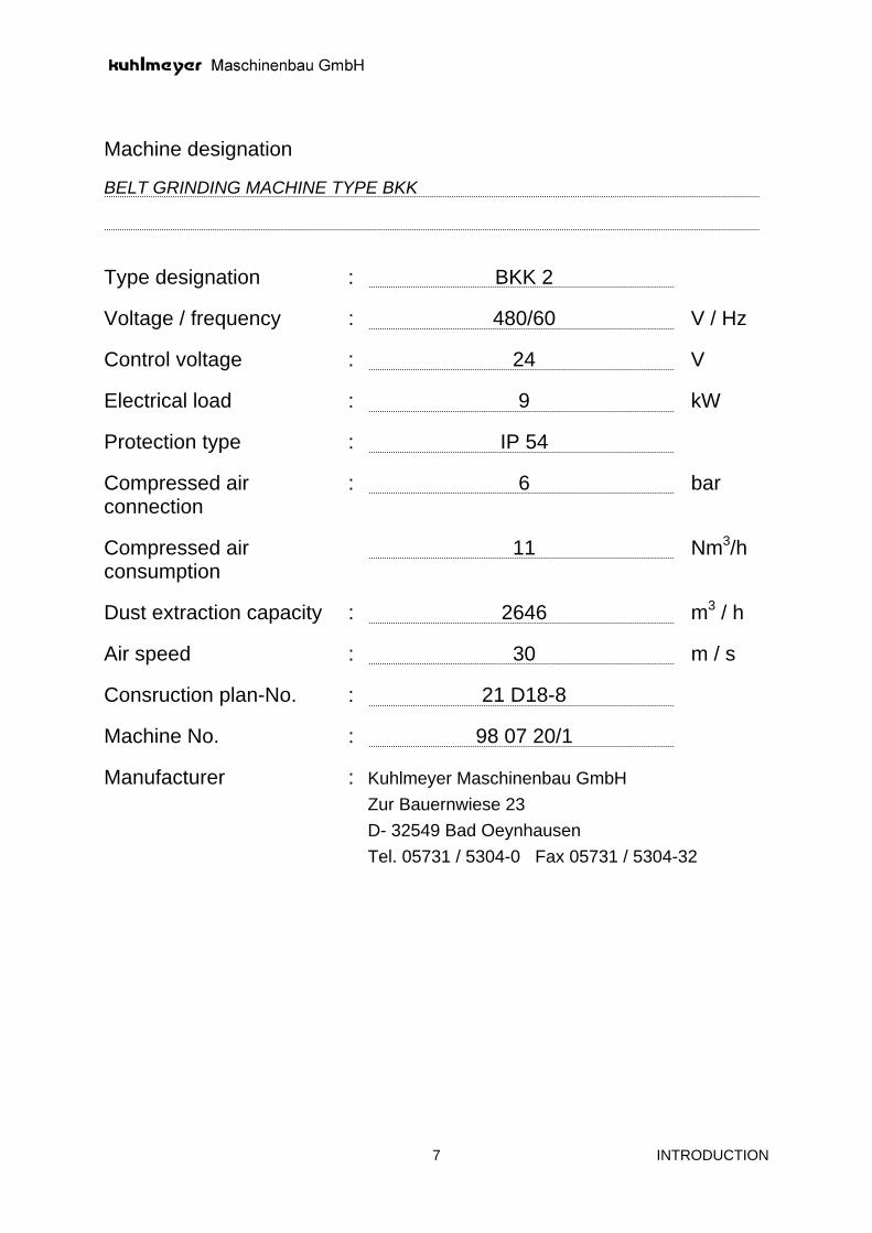
Machine designation BELT GRINDING MACHINE TYPE BKK Type designation : BKK 2
Voltage / frequency : 480/60 V / Hz
Control voltage : 24 V
Electrical load : 9 kW
Protection type : IP 54
Compressed air connection
: 6 bar
Compressed air consumption
11 Nm3/h
Dust extraction capacity : 2646 m3 / h
Air speed : 30 m / s
Consruction plan-No. : 21 D18-8
Machine No. : 98 07 20/1
Manufacturer : Kuhlmeyer Maschinenbau GmbH Zur Bauernwiese 23 D- 32549 Bad Oeynhausen Tel. 05731 / 5304-0 Fax 05731 / 5304-32
INTRODUCTION 8
1.2 OPERATING INFORMATION • This machine manual contains information covering its possible complete equipment, i.e. also
optional/additional equipment is described. For this reason you will also find explanations which do not apply to your machine.
• We reserve all rights to construction and technical data changes in the interest of technical
progress. • For this reason we cannot accept any claims resulting from this data, illustrations or drawings and
description. Rights for errors withheld. • Inform yourself about preparatory measures, operation and maintenance prior to commissioning. • This manual is intended to simplify your acquainting yourself with the machine and to use the
application possibilities in accordance with its intended use. • It contains important information to ensure safe, correct and economical operation of the machine.
Your observance will help avoid hazards, repair costs and down times and to increase the reliability and operating life of the machine.
• Observe the recognised industrial technical rules in addition to binding rules for accident prevention
contained in the machine manual and applicable in the user country (for example, UVV, VBG, VDE etc.).

INTRODUCTION 9
1.3 INTENDED USE OF THE MACHINE • The machine is exclusively intended for only sanding and polish metal.
Any other use above this is not deemed to be in accordance with its intended use. The manufacturer does not accept any liability for resulting damage. The owner company solely bears all risks.
• The intended use of the machine also includes the observance of the operating, inspection and
maintenance instructions. • The use of the machine in explosion endangered rooms is only permitted when its PROTECTION
GRADES correspond to the danger potential. • The machine may only be used for the processing of workpieces / materials which generate
inflammable and explosive dust when the machine design meets the corresponding PROTECTION GRADE.
• We expressively point out that explosive dust is created when processing solvent based lacquers, aluminium and magnesium alloys.

GENERAL SAFETY INFORMATION
10
2.0 GENERAL SAFETY INFORMATION Firstly we would like to point out that the machine is constructed in accordance with the state-of-the-art and is thus operationally safe and meets the requirements of the EC machine guide lines. Notwithstanding the above dangers can result from the machine when operated by untrained personnel, used incorrectly or not used in accordance with its intended use as laid down in this manual. This can result in − Danger of injury or to life − Danger to the machine and its surroundings − Danger to the efficient operation of the machine In order to avoid this as much as possible please carefully observe the following information: 1. Only trained and authorised personnel are permitted to operate the machine. 2. Ensure that the responsibilities for operation is observed and that no unauthorised personnel
operate the machine. 3. Together with a superior the operator must ensure that no unauthorised person operates the
machine. 4. Operation of the machine is only permitted when in perfect condition. 5. The user must notify his superior immediately of any changes to the machine which influence
safety so that the necessary steps can be taken.
All persons employed in the transport, installation, operation, maintenance or repair of the machine must have read and understood the machine manual in particular the accident and damage prevention sections marked with
It is recommended that this be confirmed in writing.
6. Under no circumstances change or put out of operation any safety devices. 7. Do not undertake any changes or conversions to the machine which may influence safety. 8. Put the machine out of operation and secure in accordance with the regulations prior to
dismantling safety devices during repair or maintenance by locking the main switch in the switch setting “OFF” using – at least – one padlock. Refit the safety devices after concluding the work and check that they operate perfectly. Only trained and authorised persons are permitted to undertake repair and maintenance work.
9. Ensure cleanliness and a tidy arrangement on and around the machine with the corresponding
instructions and controls.
GENERAL SAFETY INFORMATION
11
10. Only qualified electricians are permitted to undertake work on the electrical plant. For this work
switch off the main switch and secure against switching on again. 11. Only corresponding qualified personnel are permitted to undertake work on the hydraulic system.
After switching off the main switch release the pressure on the system and secure the main switch against switching on again. Also release the pressure on any pressure accumulators. Do not open hydraulic lines when under pressure. Check prior to starting work! Recommissioning of hydraulic plants is only permitted – also as a test – following control by an authorised expert.
The defined signal terms highlighted in this documentation are intended as safety information and warnings to avoid danger to life and health for operating or maintenance personnel and to avoid damage to property. The terms employed have the following meaning in this documentation and on the warnings on the products:
Danger !
For the purposes of the documentation and the warning information on the products danger means that death, severe injury or considerable damage to property will be encountered unless the corresponding precautionary measures are observed.
Warning ! For the purposes of the documentation and the warning information on the products warning means that death, severe injury or considerable damage to property could be encountered unless the corresponding precautionary measures are observed.
Caution ! For the purposes of the documentation and the warning information on the products caution means that light injury or damage to property could be encountered unless the corresponding precautionary measures are observed.

GENERAL SAFETY INFORMATION
12
2.1 ELECTRICAL EQUIPMENT • The main switch located in the machine switch cabinet can be secured in its off setting with at
least one padlock. • Emergency stop command units in accordance with EN 418 are installed in the switch cabinet
and at easily accessible points on the machine. The complete machine or plant stops and the tools raise when the red mushroom button on a yellow
background is actuated. The mushroom head button engages in the opened setting when actuated, only return to its original
setting once the danger has been overcome by lightly turning. • The drive motors are protected by motor protection switches, fused motor isolators,
contactors or PTC resistors. • In most cases feeding systems are protected by light barriers and light fences, to ensure that
they are quickly accessible when stationary for loading or unloading. The light barriers function in the same manner as emergency stop actuation when the plant is running.
• Wide belt sanding units are equipped with belt run-off ad belt tear switches. When actuated the drive motor is electronically braked so that the sanding belt stops within max. 10
sec.
− on motor driven machine elements such as: − machine width adjustment − table height adjustment − unit axis adjustment − Panel infeed − Vacuum lifting units − Gantry handling robots
• The end position is limited by limit switches. • Lift table and turning stations are equipped with circulating safety switching rails. • The entry of edge banding machines with roller or belt pressure beams are equipped with a safety
circuit device which prevent the pulling in of thicker workpieces or parts of the body. The feed stops when actuated.
• Edge banding machines with roller or belt pressure beams are additionally equipped with safety tug
line switches with a red switching cable located above the pressure beam in addition to the standard emergency stop buttons.
• Free running feed drive shafts of double sided edge processing machines are secured over the full
length by a safety tug line switch with a red switching cable. • Narrow belt sanding units (profile and edge sanding units) are equipped with belt tear switches.
The drive motor is switched off and the contact pressure tool raised by an automatic actuation of the switch in the event of a tear or running off of the sanding belt.
• With wide belt sanding machines the replaced belt can be started in inching operation in order to
check for a uniform run. A sanding belt running off can result in injuries to persons or damage to property.

GENERAL SAFETY INFORMATION
13
2.2 MACHINE PROTECTION DEVICES • The flaps on the noise protection hoods are provided with mechanical safety switches, the
actuation being coded to prevent manipulation. (EN 1088 and EN 954). When opening the flap the motor inside is switched off and electronically braked.
• A safety tug line switch with a red tug line is fitted between the belt discs of long belt sanding
machines. In the event of danger the operator can easily reach the tug line and switch off the drive motor and brake electronically by actuating.
• In the event of long belt sanding machines with two sanding belts arranged one after the other a
moveable plexi glass cover is provided covering the belts not in operation. • The shaft ends of the drive motor for milling, sawing etc. have a stepped right and left hand thread
at the front. Select the thread for axial mounting in accordance with the tool turning direction (clockwise or counterclockwise) so that the tool cannot loosen during operation.
• For wide belt sanding machines the intake point is protected by a safety device which prevents
parts of the body from being drawn in. The protection device arranged over the full working width acts as a positive switching device for stopping the feed.
• With wide belt sanding machines the units are almost fully encapsulated, so that accidental contact
with the sanding belt is almost impossible when the hood is closed. When changing the sanding belt take great care that the electronically braked drive motor is stationary prior to releasing the sanding belt. A colour marking is provided on the drive roller to permit better control.
• For narrow belt sanding units (profile and edge sanding units) the sanding belt is almost fully
encapsulated. Encapsulation is not possible in the cutting area. Take every precaution to ensure that during operation the flaps, slide and covers on the extraction hood are closed. Only in this manner is protection from the running sanding belt and optimum dust extraction possible.
• With narrow belt sanding units the sanding belt contact run on points onto the pulleys in the free
belt carrier are protected by protection plates. Adjust the protection and extraction hood to compensate for wear (changes to the diameter) of brushing, sanding and polishing wheels. Set the hoods so that an optimum dust extraction is guaranteed.
• Transport belts and transport chains are almost fully enclosed. At the run-in and run-out to ensure
that the slot between the protection hood and the chain plate is smaller than 8 mm. In spite of this extreme care should be taken at these points, in particular when the chain is provided with dogs or has moulded chain plates.
• Edge banding machines provided with a reciprocating machine table to transport the workpieces
are provided with an electro-pneumatic controlled protection device for milling tools.

GENERAL SAFETY INFORMATION
14
• Moving machine parts such as:
− hydraulically swivelled sanding units − pneumatically moved infeed mechanism − motor operated conveying systems
are protected by protection fences in accordance with EN 294 and EN 349.
2.3 SAFETY INFORMATION FOR OPERATION, MAINTENANCE AND REPAIRED The product described has been developed, tested and documented in accordance with the current safety standards. For this reason under normal circumstances no danger with regards damage to property or damage to health can result when the project handling, installation and operation are observed in accordance with the technical safety instructions. Take special note of the following danger instructions with reference to your own safety and the safety against damage to the machine:
WARNING ! • Only correspondingly qualified persons are permitted to undertake
repairs to units supplied by us. Only use original exchange parts or components. Unauthorised opening and incorrect repair work can result in death or severe injury as well as to considerable damage to property.
• Always remove the mains plug or open the isolation switch prior to
opening the units. • When changing fuses only use the specified types. • Do not put batteries in the fire and do not solder to cell bodies,
danger of explosion exists. Do not open lithium or mercury containing batteries and do not recharge, only use the same type when exchanging!
• Dispose of batteries or accumulators in the appropriate manner:
special waste. • When using monitors:
Incorrect intervention, in particular changes to the high voltage or fitting a different screen tube can result in a higher X ray level. Units changed in this manner are not permitted and must not be operated.

GENERAL SAFETY INFORMATION
15
If measurement and testing is required on active units ensure that the specifications and performance instructions of the accident prevention regulations are observed. Use suitable electrical tools.
WARNING ! • Certain parts of the unit/system which could carry dangerous
voltages are accessible after removing the housing or contact protection.
• Only correspondingly qualified personnel are permitted access to
this unit/system. • These personnel must be familiar with all sources of danger and
maintenance measures in accordance with the data in the corresponding documentation.
• The perfect and safe operation of the product requires correct
transport, storage, installation and assembly as well as careful operation and maintenance.
• Ensure the observance of the safety and accident prevention
regulations for specific individual cases. • Fitted units for housings or cabinets can only be operated and used
in fitted condition and as table units or portable with the housing closed.
• Fit a mains isolator or a fuse in the building installation for units with
fixed connections (permanently installed units/systems) without an all pole mains switch and/or fuses; connect this device to a ground wire.
• Locate the earthed protective contact socket for the unit as close to
the unit as possible and within easy access for units with a fixed connection (permanently installed units/systems) without all pole mains switches and/or fuses.
• Prior to commissioning units with mains voltage check that the set
mains voltage range matches the local mains voltage. • Emergency stop devices in accordance with EN 60204/IEC 204
(VDE 0113) must remain effective in all operating modes of the automation system. Releasing the emergency stop devices must not generate uncontrolled or undefined movements.

GENERAL SAFETY INFORMATION
16
WARNING ! • Prerequisite for safe operation is the perfect function of the
emergency stop device • Do not attempt to put safety switches and safety light barriers out of
operation • Check the function of the emergency stop equipment once per
month including:
− Safety switches on flaps and doors − Safety switches at intake points − Emergency stop mushroom buttons − Emergency stop tug lines − Safety light barriers − Safety rails on lift and turning stations
WARNING ! Belt sanding units are fitted with belt tear and/or belt run off safety switches. When actuated the contact pressure rollers rise and the motor is switched off and the wide belts braked. Check the function of the safety switch once per month. In the event of a malfunction the belts make contact with hoods, stands and supports generating sparks.
IMPORTANT – DANGER OF FIRE !

GENERAL SAFETY INFORMATION
17
WARNING !
DANGER OF FIRE !
DANGER OF EXPLOSION ! When sanding lacquer highly explosive dusts can be generated. Aluminium dust can form an explosive mixture with air. For this reason clean machine and workplace after each shift. Take particular precautions against accumulations in protection and extraction hoods.
WARNING ! In spite of the installation of extraction hoods chips can build up within the milling unit noise protection hoods. Clean noise protection hoods several times per day dependent upon the chips produced. Excessive chip build up can block the motor ventilation hoods causing the motor to overheat.
DANGER OF FIRE !

NOISE AND DUST EMISSION 18
4. NOISE AND DUST EMISSION When determining the size of the dust extraction plant take into consideration that an air speed of v = 30 m/s is required at the suction openings. Do not reduce the size of the duct connections to the dust extraction hoods. Wet separators must be used to extract aluminium dust. An optimum dust collection is the prime criterion to minimise the dust concentration at the workplace. As the dust extraction is only effective directly in front of the suction opening we have taken every effort to design the extraction hoods such that they are as close as possible to the suction opening. Connect the units using flexible hoses. Refer to the corresponding installation plan for the arrangement of the dust extraction sockets and their diameters. Refer to the following table for the necessary extraction capacity (volume flow in m3/h). During the construction of the extraction hoods attention was paid to ensure an effective dust extraction and to meet all accepted guidelines and regulations regarding working safety and environmental protection (Gef Stoff V, TRGS 900, MAK value, TA air, Vdi guidelines 2262, ZH 1/32). However, there are some machines, for example long belt sanding machines, profile sanding machines, brushing machines which do not permit a 100% dust extraction for construction reasons. If necessary, install these machines in a separate rooms or cabins.

PREPARATORY MEASURES 19
5.0 PREPARATORY MEASURES
5.1 MACHINE TRANSPORT, WEIGHT, DIMENSIONS When unloading with a forklift truck ensure that the fork lengths are as large as the width of the machine bed. The underside of the machine bed is not enclosed over the full length. The machine is bolted to wooden beams for transport. Overseas transport is made in corresponding crates in accordance with the machine size. The machine is prepared in advance by welding in polyethylene foil together with a drying agent. For shorter see transport a conserving agent is applied and the machine packed in a container. The control panels are normally packed on the wooden beams provided for the machine. To relieve the guides, lifting spindles, motor rockers etc. the units and machine table are supported by wooden beams or secured with support screws and brackets. Accessories and small parts are packed is a separate crate and included with the machine. To facilitate handling when loading and unloading the hoods and cladding plates are in part removed and packed separately. Ensure that unloading and transport to a predetermined location in the hall are performed by trained personnel. Where possible unload the machine with a crane and crane traverse. Ensure that no pressure can be exerted by the cable on the units, machine table etc. Support the cable against the bed with wooden blocks. Dimensions in mm
Length x width x height
Weight in kg
Case 1 5000x2400x2600 5000
Case 2
Case 3
Case 4
Case 5
Case 6
Case 7
Case 8
Total 5000 kg

PREPARATORY MEASURES 20
5.2 REMOVING PACKING MATERIAL and RUST PREVENTATIVE Do not remove the wooden beams bolted below the machine until the machine is at the final location and the control panel has been removed. When steering with a lifting carriage, hydraulic lift trucks and winches always ensure that the contact point is below supporting, rigid elements of the machine bed and not below panelling. Screw the supplied setting screws into the machine feet before depositing the machine on the floor and after removing the beams. Place a steel plate 100 x 100 x 10 beneath each setting screw. In part the supports, securing bolts and securing brackets can only be removed after connecting the compressed air and power supply. Prior to dispatching the machine all bare metal parts are coated with a rust preventative. Prior to commissioning remove this agent with washing petroleum or washing oil. Take great care when performing this, Danger of fire exists.


INSTALLATION OF THE MACHINE 22
6.0 INSTALLATION OF THE MACHINE
6.1 MACHINE INSTALLATION Install the hydraulikunit outside the movement area of the machine with dust protection. For safety reasons the hydraulic oil is drained for the transport. Fill the container with hydraulic oil in accordance with the marking on the type plate and the oil level display Only use high precision spirit levels for aligning the machine with a display of 0.02 mm incline over 1000 mm. Use the machine bed as support in the longitudinal and cross direction. Lock the setting screws after aligning. For production reasons the machine bed and workpiece transport system of longer machines is composed of several sections which must be dismantled for transport. The installation of these machines requires a company fitter with the corresponding professional knowledge. The same applies to double sided machines and machines with a tandem arrangement. After aligning fit the panelling, protection hoods, extraction hoods and bellow covers. The machine are finished installed electrically, pneumatically and hydraulically. Hydraulic units are linked to the machine using high pressure hoses with a length of 2 metre in normal cases and 5 metres for explosion protected units. Fill the container with hydraulic oil in accordance with the marking on the type plate and the oil level display.

INSTALLATION OF THE MACHINE 23
6.2 ELECTRICAL SYSTEM AUTOMATIC MACHINE FUNCTION The width in double-sided operating machines can only be adjusted when the clamping devices are not in operation. Ensure that the machine is not switched on until the hydraulic unit has been filled with HLP 22 oil and the compressed air has been connected. Reset the EMERGENCY STOP switches (1) prior to switching on the unit. Prior to fitting a grinding belt, check whether the motor is turning in the direction indicated on the guard plate. The machine is delivered with the electrical system ready for operation. The electrical equipment has been created in accordance with the valid VDE accident prevention regulations and EC guidelines. The switching devices are conveniently arranged in a separate switch cabinet. A command panel OP 17 with a START - EMERGENCY STOP button and control lamp as a button has been installed for machine operation. A cable screw connection has been provided under the switch cabinet for connection to the power supply. The lockable main switch is in front of the switch cabinet door. According to VDE, the supply fuses must be located outside the machine. Mandatory circuit diagrams are supplied with each machine and are located in a pocket in the switch cabinet door. The air pressure of the contact pressure tool is regulated via a proportional valve. The technical documentation of the command panel OP 17 is on point 11.0.
1

INSTALLATION OF THE MACHINE 24
6.3 ELECTRICAL CONNECTION The electrical installation was performed in accordance with VDE regulations and the EC machine guidelines. Generally the main switch is isolated from all not earthed conductors and located at the right hand side of the machine. The lower section accommodates the screw fittings for the mains supply. PROCEDURE • Check that the voltage and frequency data shown on the type plate
matches your mains data.
• Check that the fuses for your mains line match the rating data on the type plate.
• Switch off the main switch (Setting 0). • Switch off the main switch for your mains line • Insert the cable connection machine - switch cabinet.
• Perform a precautionary check of all connection screws, terminals and
fuses.
• Switch on all motor protection switches and automatic fuses • Connect supply lines to the main switch terminals.
• Take care when connecting to a right hand rotating field (check with
rotating field instrument) • Switch on the main switch for your mains line
• Switch on main switch.
• After actuating the “controls/on” button ensure that the green control
lamp is displaying operational.
All electrical components on machines in explosion protected execution are explosion protected in accordance with the European standard EN 50014-50020 and the IEC regulations. Non explosion protected components such as, main switch, fuses, contactors, cut-out switches, frequency changers etc. are installed in a separate switch cabinet. This cabinet must be installed outside of the explosion endangered area. The connection cable between the explosion protected terminal box and the machine and switch cabinet is not included in the scope of delivery, as the length is dependent upon the local conditions.

INSTALLATION OF THE MACHINE 25
6.4 MAGNETIC CLAMPING PLATES As a rule, the machines are equipped with magnetic clamping plates 125 x 500 mm (1), which are arranged horizontally on the machine stand for double-sided operating machines or vertically for single-sided operating machines at right angles to each other on stands (2). The clamping plates may be horizontally and vertically adjusted, and swivelled through 90° by means of the stands. The positions are indicated through mechanical position displays (3) or scales (4). As the horizontal adjustment is only executed under special circumstances, we tightened the clamping screws by means of a nut (5). For vertical adjustment and swivelling, the clamping screws are secured by means of clamping levers (6). In machines used to achieve high removal rates (safes, battery boxes), the clamping plates may be accommodated on supports (7) and, if necessary, equipped with gear motors for axis adjustment. Please refer to the enclosed suppliers’ operating instructions for more details concerning magnetic clamping plates. As a rule, the magnetic clamping plates, supplied by the rectifier accommodated in the switch cabinet, must be switched on and off by means of a 3-position foot switch.
1
2
3
4

INSTALLATION OF THE MACHINE 26
6.5 COMPRESSED AIR CONNECTION COMPRESSED AIR IS ONE OF THE MOST EXPENSIVE SOURCES OF ENERGY! The operating safety and operating life of a pneumatic plant is primarily dependent upon the compressed air quality. Ensure that clean and dry air is supplied to the machine. A filter regulator is fitted at the front of the machine to ensure that all soiling and liquid components will have no access to the consumers. This has a size R 3/8 or R 3/4 dependent upon the number of consumers. Condensed water contained in the compressed air is separated in the filter. The condensate collected in the filter dish is discharged by an automatic condensate drain system. Condensate can collect in the machine compressed air accumulator. Open the stop cock to drain off the water once per day. It is recommended that the compressed air network be connected via a stop valve, permitting the pressure to be removed when the machine is stationary. The air for the sanding belt blow down device is generally tapped off in front of the filter regulator. The compressed air must have a pressure of at least 6 bar. The subsuppliers original operating instructions and spare parts lists are included.

INSTALLATION OF THE MACHINE 27
A filter regulator (1), on which a 9 mm dia. compressed air hose must be connected, is fitted on the machine stand. Place a stop valve in the supply line, to depressurize the machine during standstill or repair work. Check the hoses and screw connections for leaks at regular intervals. The compressed air for the grinding belt tension is regulated on the pressure regulator by means of pressure gauges (2), arranged in the machine stand. Special supplier operating instructions are enclosed for filter regulator (1) and pressure regulators (2). The stop cam, arranged on the table, is moved by means of a pneumatic cylinder (4). The secondary pressure of the filter regulator (1) is applied at the solenoid valve (5) to control the cylinder.
1
2
4
5

INSTALLATION OF THE MACHINE 28
6.5.1 PNEUMATIC VALVES The line pressure is correspondingly reduced by means of regulators 1, 2 and 3 described in section 6.4. The regulator for the grinding belt tension should be set to approx. 3 bar.The belt tensioning cylinder, integrated in the guide unit for the drive motor, is moved by means of the hand lever valve (1). The air pressure to control the contact pressure tool (2) should be set to approx. 5 bar. The tool is controlled by means of the solenoid valve (3) and proportional valve (4). Primarily, the pressure set at the filter pressure regulator is applied to both valves. Raising of the tool cylinder and cooling of the grinding shoe is activated during the grinding process by means of the solenoid valve (3).The approach or pressing of the tool is controlled via the 3-way proportional valve (4).The secondary pressure ranges between 0.1 and 5 bar depending on the setting in the switch cabinet. (Please refer to the supplier’s operating instructions for the function description)
1
2 4 3
INSTALLATION OF THE MACHINE 29
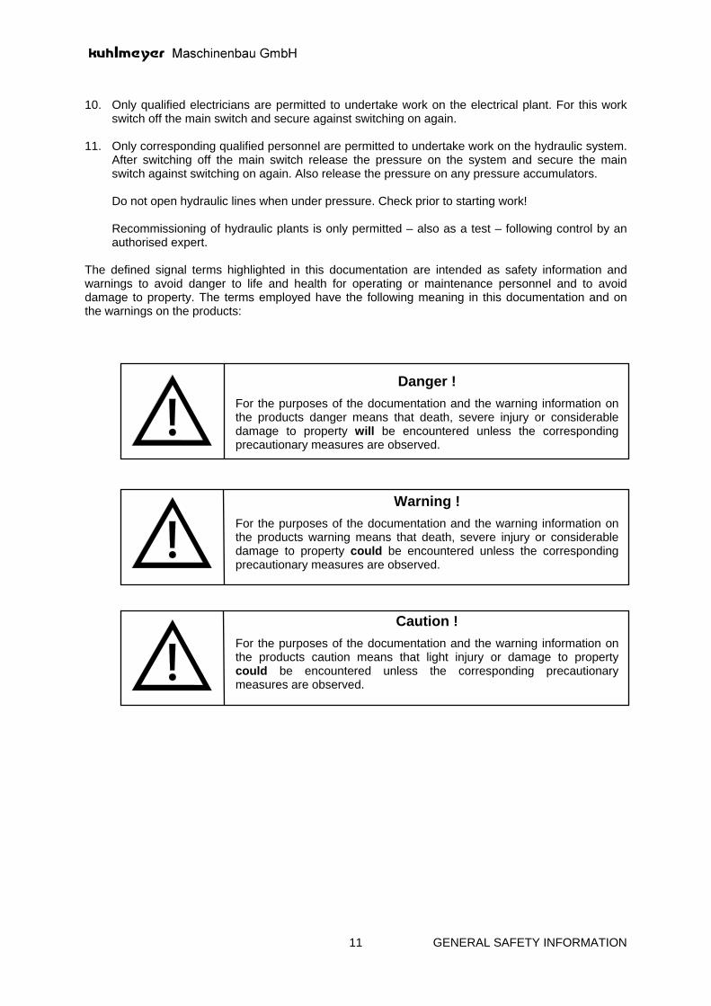
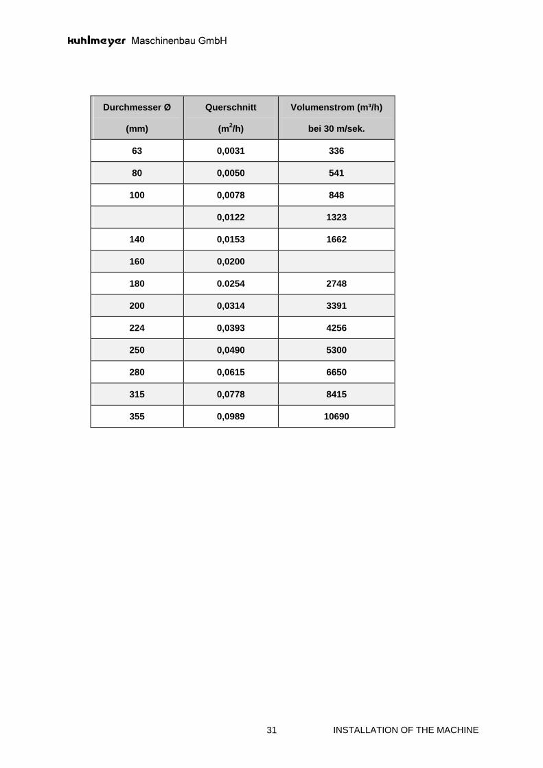
6.6 CONNECTION TO THE DUST EXTRACTION When determining the size of the dust extraction plant take into consideration that an air speed of v = 30 m/s is required at the suction openings. Do not reduce the size of the duct connections to the dust extraction hoods. Open the inspection flap (2) daily, and check to ensure that the passage is unobstructed. Clogged extraction hoods and pipes reduce the extraction capacity. Inadequate dust extraction leads to soiling of the machine and impairs the function and service life of bearings and guides. An insufficient extraction capacity negatively influences the machine function and sanding results. An optimum dust collection is the prime criterion to minimise the dust concentration at the workplace. As the dust extraction is only effective directly in front of the suction opening we have taken every effort to design the extraction hoods such that they are as close as possible to the suction opening. Each grinding unit is equipped with a dust extraction hood (1) having a 125 mm socket diameter. Use flexible metal extraction hoses for the dust extraction. Take the large movement range of the units into consideration when cutting the hoses to size. Refer to the corresponding installation plan for the arrangement of the dust extraction sockets and their diameters. Refer to the following table for the necessary extraction capacity (volume flow in m3/h).
1
2
INSTALLATION OF THE MACHINE 30
During the construction of the extraction hoods attention was paid to ensure an effective dust extraction and to meet all accepted guidelines and regulations regarding working safety and environmental protection (Gef Stoff V, TRGS 900, MAK value, TA air, Vdi guidelines 2262, ZH 1/32). However, there are some machines, for example long belt sanding machines, profile sanding machines, brushing machines which do not permit a 100% dust extraction for construction reasons. If necessary, install these machines in a separate rooms or cabins.
INSTALLATION OF THE MACHINE 31
Durchmesser Ø
(mm)
Querschnitt
(m2/h)
Volumenstrom (m³/h)
bei 30 m/sek.
63 0,0031 336
80 0,0050 541
100 0,0078 848
0,0122 1323
140 0,0153 1662
160 0,0200
180 0.0254 2748
200 0,0314 3391
224 0,0393 4256
250 0,0490 5300
280 0,0615 6650
315 0,0778 8415
355 0,0989 10690

COMMISSION 32
7.0 COMMISSIONING
7.1 INSTALLING AND SETTING THE GRINDING UNITS The sturdy bearing of the swivel axis (1) is accommodated in the machine stand together with the hydraulic swivel cylinder. The swivel axis is screw connected to the swivel console (2). The absolute angle between the vertical guide and clamping surface was created at the factory by means of the pressure screws (3). The vertical guide was assembled on the swivel console with the integrated hydraulic cylinder. The concertina walls must be checked at regular intervals to protect the linear guides. A hardened curved element (5) has been fitted to support the grinding unit. While the two inner guide rollers are running in fixed bearings, the two outer roller may be lowered set by means of cams. Brushes (6) have been arranged to clean the running surfaces. Check the brushes at regular intervals, and change the elements when they no longer have a cleaning effect. A graduated collar (7) with T-groove and 90° scale is mounted on the swivel axis. Switch cams (8) are arranged in the T-grooves according to the desired swivel position. The cams are detected by means of the inductive sensors (9) and the unit is positioned accordingly. For safety reasons the 0°-Position of the grinding unit is set be means of a limit switch (10). This area should be kept extremely clean, in order to avoid switching errors.
4 6 7 8 9 10
1 2 3 5 1

COMMISSION 33
The vertical movement is controlled upward by means of an inductive sensor (11) scanning the workpiece height. The bottom end position, which is usually constant, is controlled by means of a limit switch, actuated by means of the switch cam arranged adjustable in the C-profile. Only when the bottom final position must be raised due to the arrangement of additional clamping or insertion devices must the cam be displaced accordingly. To permit vertical movement, the grinding unit is arranged on rail guides with V-shaped guide geometry running in slide bearings. Two hardened and ground V-guide rails (12) are fitted to the vertical pillar. Two M-rails with a PTFE coating are arranged in the support (13). Although the rail guides distinguish themselves through their particularly high wear resistance, the 8 pressure screws (14) per grinding unit must be readjusted folllowing a running-in period of approx. 4 weeks.
11
12
13
14

COMMISSION 34
7.2 CONTACT PRESSURE TOOL When changing the tool, slide the retaining bracket of the sensor (4) to the rear or remove. During reassembly, ensure that the sensor is arranged in its original position. The grinding belt is pressed against the edge to be processed by means of an elastic, air cooled contact pressure tool (1) covered with a special slideway lining. Lowering and raising occurs electro-pneumatically. The intensity of the contact pressure is determined by the compressed air pressure existing at the cylinder of the tool holder (2). The compressed air is regulated by means of a proportional valve, responding to the setting of the data in the operator panel. The various grinding or swivel positions of the grinding unit can be feed in the operator panel. Special instructions have been enclosed concerning the function of the proportional valve. Check the slideway lining of the contact pressure tool once a day. For this purpose, remove the inductive sensor after releasing the retaining bracket and then pull out the tool. A glass bead lining manufactured by 3M must be recoated with graphite paste at least each time the grinding belt is changed. The precoated slideway lining distributed by VSM, amongst others, must be replaced once the graphite paste is worn off. In order to achieve a longer service life of the slideway lining, the tool is cooled by means of compressed air via the hose (3).
4 1 3
2

COMMISSION 35
7.3 PLACING AND ADJUSTING THE GRINDING BELTS Ensure that the grinding belt is standing still before releasing the belt tension. Do not reach into the running belt!. Following the belt change, ensure that the clamp for the hood mounting is fastened. The motor (2) with rubber coated drive pulley is brought to its front position by actuating the 5/2 way valve (1). Once the wing nut (3) has been loosened, the clamp for the additional hood mounting may be folded to the side. The grinding belt with the 100 x 2240 dimension may now be slipped over the vertical guide pillar and placed on the three belt pulleys. The running direction of the grinding belt is marked on the rear of the grinding belt. It must coincide with the running direction arrow on the guard plate. The belt pulley moves slowly into clamping position by actuating the valve (1). The moving speed may be changed at the throttles arranged in the valve outlets. The clamping pressure should range between 3 and 4 bar. In order to check whether the belt is centered on the pulley, turn the grinding belt manually in the direction of the dust extraction hood. If the belt runs off, tilt the drive pulley/motor accordingly by means of the setscrew (4).
2
1 3
4
COMMISSION 36
7.4 GRINDING BELTS, STRUCTURING BELTS, POLISHING BELTS When using these belts, pay particular attention to the admissible peripheral speed. Belt dimension : 100 x 2240 mm All grinding belt manufacturers have a selection table, from which the respective grinding belt qualities and types may be selected according to the different applications and tasks. Zircon-corundum textile belts have proven themselves outstandingly for welding seam processing in steel. The primary problem when grinding aluminum is the greasing and clogging characteristics of the metal. Therefore, in order to increase the service life of the belts, they should be misted with a liquid spray oil or a liquid recommended by the grinding belt manufacturer. Grinding fleece belts, also known as Scotch-Brite-belts, are preferably used for finishing and surface processing of VA and other NE metals. These belts are available in different grit grades. Molton belts, coated with different waxes according to the desired surface, are normally used to polish corners.

COMMISSION 37
7.5 HYDRAULIC SYSTEM The hydraulic system is arranged outside the danger zone, i.e., outside of the machine barrier. In explosion protected machines, the distance between the machine and the unit must be at least 5 meters. According to the safety regulations, the transport must not take place with a filled tank. Prior to commissioning/start up, fill the unit hydraulic oil HLP 22. Ensure that the degree of purity is at least 10 µm. Fill the oil through the provided infill socket (1) or through the hydraulic filter (2). After filling, the unit should rest for at least 24 hours to let out the air in the oil. Special instructions have been enclosed for the maintenance of the hydraulic unit and filter. Check the filter display once a week. When the display unit indicates the red area, change the filter element and the oil. Each hydraulic cylinder is controlled via two one-way restrictors (3). The cylinder speed may be changed by means of the knurled screws, after the set screws(5) have been loosened. The speed is to be regulated through the valve for the back flowing oil! If the hydraulic pump does not supply oil after the tank has been filled, add a few drops into the pump housing after opening the screw connection (4).
1 4 2 5 3 9 6
COMMISSION 38
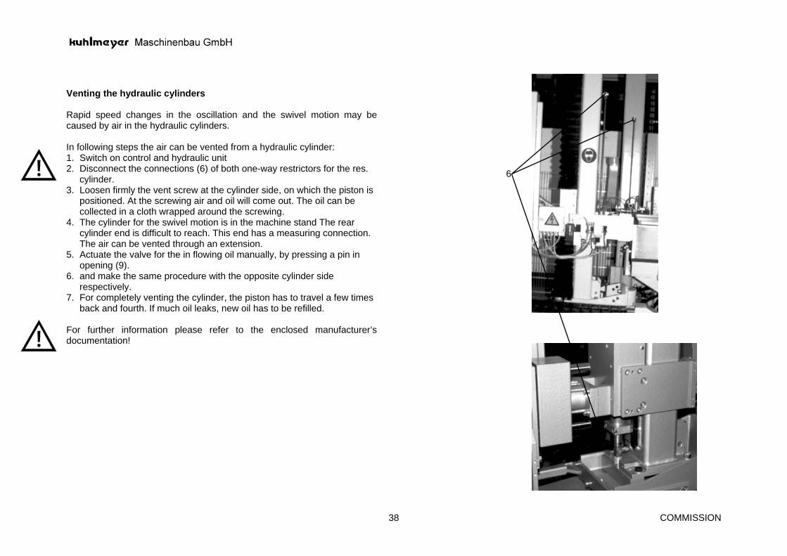
Venting the hydraulic cylinders Rapid speed changes in the oscillation and the swivel motion may be caused by air in the hydraulic cylinders. In following steps the air can be vented from a hydraulic cylinder: 1. Switch on control and hydraulic unit 2. Disconnect the connections (6) of both one-way restrictors for the res.
cylinder. 3. Loosen firmly the vent screw at the cylinder side, on which the piston is
positioned. At the screwing air and oil will come out. The oil can be collected in a cloth wrapped around the screwing.
4. The cylinder for the swivel motion is in the machine stand The rear cylinder end is difficult to reach. This end has a measuring connection. The air can be vented through an extension.
5. Actuate the valve for the in flowing oil manually, by pressing a pin in opening (9).
6. and make the same procedure with the opposite cylinder side respectively.
7. For completely venting the cylinder, the piston has to travel a few times back and fourth. If much oil leaks, new oil has to be refilled.
For further information please refer to the enclosed manufacturer’s documentation!
6

COMMISSION 39
7.6 WIDTH ADJUSTMENT Check, clean and grease the component parts once a month. Always ensure that the concertina walls are screw connected well to the machine bodies and are absolutely tight. The RH machine stand is permanently attached on the machine bed. The LH machine stand is motorically adjusted according to the workpiece width. In the standard version, the adjustment is made at rapid and creep speed. For automatic width adjustment, the workpiece dimension is entered into an operator panel (1). Once the start key has been actuated, the LH machine stand automatically moves to a width approx. 5 mm larger than the set set point value. Only after the workpiece is located in the machine and the start command has been given, does the machine move so far to the right until a limit switch attached on the stand is activated by the workpiece. The motor for the width adjustment stops and the clamping devices close. At the end of the grinding process, the movable machine stand moves 5 mm to the left again, once the clamping device is released. In this manner, workpiece tolerances are taken into consideration. The shaft encoder (2) for the control of the automatic width adjustment is accommodated on the drive side beneath the cover hood (3). The width is adjusted via 2 spindles (4), the bevel gear (5) and the gear motor (6). Limit switches for the workpiece limitation have been provided on both end positions.
1
3
2
6 5
4 4

COMMISSION 40
7.7 INSERTING THE WORKPIECES When grinding is to be undertaken on a machine beneath closed housings, containers, lids and hoods, the machine stands are equipped with magnetic clamping plates arranged horizontally. The RH clamping plate is equipped with two and the LH clamping plate with one adjustable stop cam (1) to position the workpieces. When processing heavy workpieces, electro-pneumatically actuated lifting roller rails (2) may be fitted in addition to the magnetic clamping plates. Once the workpieces have been positioned against the stops, actuate the foot switch (3). When processing frame elements beneath open housings or very heavy component parts (safes), the magnetic clamping plates (6) are arranged vertically. A roller table (7) is provided as support to allow easy turning of heavy workpieces.
7 6 2 3

COMMISSION 41
For precise positioning, single-sided operating machines are equipped with an electro-pneumatically controlled stop cam (8), swinging out of the work table of the grinding belt once the magnetic clamping plates have been switched on. The sensor (9) scanning the workpiece height is accommodated on the contact pressure tool. If the workpiece has not been inserted properly or is not square, the sensor cannot recognize the workpiece edge resulting in switching errors. Double-sided operating machines may also be used on one side for grinding small workpieces. This requires fitting a rear stop (10). The hinge up rear stop may be moved on the brass rails (11) according to the workpiece dimension once the clamping lever (12) has been released.
10 12 9 11 8

COMMISSION 42
7.8 SCANNING THE WORKPIECE HEIGHT For workpieces higher than 150 mm, the height is automatically scanned by means of a sensor (1) accommodated on the tool. When the sensor has reached the top edge of the workpiece, the tool must not yet lift off. The time point for lift off (overflow) may be influenced via the PLC timer. The tool lifts off at the workpiece bottom edge once the limit switch (2) has approached the adjustable cam (3). The sensor (1) fastened on the tool carrier by means of a retaining bracket must be displaced or removed during a tool change. Ensure that the sensor is always screw connected in its original position. Slight turning or displacing leads to switching errors or destruction of the sensor. For workpieces with an edge height up to 150 mm, the path of the grinding unit is determined with the aid of the limit switch (2) and the time set on the PLC. Workpieces with a height lower than 80 mm are processed with continuously oscillating grinding units. The appropriate program may be invoked by means of a selector switch accommodated in the operator-panel.
2 3 1

COMMISSION 43
7.9 OVERCOMING MALFUNCTIONS A) The contact pressure tools lifts off during the vertical movement of the
grinding unit. ∗ The sensor accommodated on the tool carrier was not correctly
positioned. ∗ The workpiece was not correctly positioned and the sensor does not
detect the workpiece edge. ∗ The workpieces are not square. B) The machine does not start. ∗ The clamping device was not activated. ∗ An EMERGENCY STOP button was not reset. ∗ Check safety light barriers, release cord switches, safety positioning
switches, etc. C) The hydraulic pump does not feed during commissioning/start up. ∗ Add a few drops of oil into the pump housing after removing the marked
plug. D) The hydraulic unit switches off. ∗ Check oil level.

FUNCTION OF MACHINE 44
8.0 FUNCTION OF MACHINE
8.1 SAFETY INSTRUCTIONS
8.2.1 ELECTRICAL EQUIPMENT The electrical installation has been performed in accordance with VDE and EC machine directives (upon request also in UL or CSA execution). During operation some electrical parts always carry dangerous voltage loads. Unqualified access to the system or non observance of warning information can result in serious injury or damage to property. Access to this system is only permitted to qualified personnel, who are authorised to install, assemble, commission or operate the product. Adhere to the safety instructions when employing electrical controls, frequency changers, electronic braking units etc. In all cases a copy of these operating instructions in placed in the switch cabinet to ensure that all qualified persons have access to this special manual.
8.2.2 HYDRAULIC SYSTEM The hydraulic system has been constructed in accordance with the latest state of the art and the currently applicable safety regulations. Prior to switching on the hydraulic system ensure that no person in within the movement area of the hydraulically driven units. Only undertake work on the hydraulic system when the system is depressurized.

FUNCTION OF MACHINE 45
8.2.3 MACHINE HANDLING The machine has been developed and constructed in accordance with the latest technical knowledge, taking the EC machine directives into account. Naturally, such a machine represents points of danger which we would like to emphasize. For this reason strictly adhere to the following instructions in addition to the generally valid safety regulations. • Read the operating instructions attentively
− in order to avoid faulty operation − to recognise points of danger
• Only trained personnel are permitted to operate the machine. • Do not operate the machine with long hair or wearing loose fitting clothing. Danger of becoming
caught up in the machine. • Do not remove protective fences, covers and protection hoods during operation of the machine. • Only qualified and experienced personnel are permitted to work on the electrical system. • Always switch off the machine electrical power supply when setting, maintain or repairing the
machine. Secure the main switch with a lock. • Never touch running tools such as grinding belts, grinding wheels, polishing disks, cutters etc.
Even tools which are decelerating are extremely dangerous. • Depressurize the hydraulics before undertaking any work on the system. • During the work on/at metal processing machines safety glasses need to be used all the time.
8.2 DESCRIPTION OF MACHINE FUNCTIONS In many product sectors, the welded corners of component parts must be grinded. A high surface quality is expected for painting corners of housings, switch cabinets, hoods and safes. For shuttering frames and VA kitchen components, it is necessary that the corners are absolutely accurate to size following the grinding process. With the BKK, this operating process can be carried out semi or fully automatic, depending on the machine version. As a semiautomatic machine, it is manufactured in a single and double version. In the double-sided working machine a fixed grinding unit and a grinding unit adjustable from 300 mm to max. 2200 mm is arranged on a machine bed. The belt grinding units swivel by a maximum of 90° and can execute a vertical movement up to 1600 mm. An elastic pressure shoe, controlled via proportional valves, presses the grinding belt against the edge to be processed. The sequences are controlled by a PLC Simatic S7. Depending on the shape and material, workpiece clamping takes place by means of magnetic clamping plates, pneumatic and hydraulic clamping cylinders or vacuum clamping devices. The throughfeed belt grinding machine type BKK 4 is predominantly used in series production lines. The component parts coming from the welding machine are supplied to the grinding machine via an angled roller conveyor. Transport in the machine takes place on synchronously driven chains. The welded corners are processed by means of four grinding units during the cycled throughfeed.

MAINTENANCE AND REPAIR 46
9.0 MAINTENANCE AND REPAIR
9.1 GENERAL INSTRUCTIONS Regular and meticulous care of the machine form the best prerequisites for a good working result and a long machine operating life. Warning! Always ensure that the machine is switched off and the main switch secured with a lock when working on the machine.
Warning! Release the pressure of the system when working on the hydraulics.
Ball bearings Any ball bearings are maintenance free the grease filling is sufficient for the operating life of the machine. Clean the motor ball bearings after 3000 operating hours and fill with new roller bearing grease. Exchange the ball bearings in the event of unfamiliar noises or extreme heating. Drive motors The air cooled drive motors are maintenance free. In order to guarantee a perfect surface cooling of the motors clean the cooling ribs and air slots in the ventilation hoods at regular intervals. Switch cabinet The switch cabinet doors, flaps and covers are provided with seals. Nevertheless fine sanding dust can enter the interior. Check the interior of the switch cabinet at regular intervals and remove the dust deposits carefully with a vacuum cleaner. Check the filter mats of switch cabinets with ventilators once per week and clean with water or compressed air. Compressed air network Check the compressed air network once per month. Leaking screw fittings and porous hoses lead to malfunctions and considerable compressed air losses. COMPRESSED AIR IS ONE OF THE MOST EXPENSIVE SOURCES OF ENERGY. Install a stop valve in the machine supply line. Turn off the compressed air supply with each stoppage of the machine.

MAINTENANCE AND REPAIR 47
Guide covers Support, lifting spindles, machine bed guides etc. are fitted in part with concertina covers, spiral spring covers or similar depending upon the conditions to protect against dirt and damage. It is unavoidable that dirt collects on the components beneath the covers. Open the covers twice per year and check the guide and spindle elements arranged below. Clean the spindles of the width adjustment every six month and lubricate using roller bearing grease. Always check the slideway protector for leaks! Ball guide units Linear ball guide units and rail guides are provided with sealing rings acting on both ends. The outer sealing lip prevents the ingress of dirt, the internal sealing lip prevents premature loss of the lubricant. It is not avoidable that - primarily with sanding machines - fine dust enters the ball guides forming a sticky mass together with the lubricant. In this manner the easy running of the guide elements will be impaired leading to major malfunctions. Check ball guide units once per month, clean, grease and reseal, if necessary. We recommend the use of lithium soap grease in the consistency class NLGi 2 DIN 51818 as lubricant. Clean the guides of the tool holder, oscillation and belt tension, daily. Cylinder Reoil the belt tensioning cylinder monthly, and the tool holder cylinder once a week. Add 4 - 5 drops of liquid oil into the cylinders after opening the screw connection. Switch the cylinders several times, to permit the excess oil to emerge through the exhaust opening and to be removed.

MAINTENANCE AND REPAIR 48
Lubricating schedule for KUHLMEYER sanding and grinding machines
Lubrication point
Make of Lubrikation
Lubricant Datas Marking Lubrication Interval
SHELL TEXACO
Variable speed drive
oil extreme-pressure transmission oil C-LP 100 -140 cSt/40“
VG 150 Oil gauge 5000 H
Omala 150 Meropa 150
Spur gearing oil 172 cSt/50° 23° E/50°
first time after 300 h, then 5000 h
Omala 150 Meropa 150
Open driving chain
adhesive 135-165 cSt/40° 20° E/50°
VG 150 500 h Tonna T 220 Metac Oil H 150
Transporting chain plates
grease Vaseline clean and lubri monthly
Techn. Vaseline 8401
Merkur 71
Sliding guide-ways, supports stands
grease multi-purpose grease as required Retinax AM Moltytex-Grease EP 2
Sliding guide-ways with brushings
grease lithium base grease consistency 2
K 2 K violett
only, if very dirty Alvania 2 Multifak 20
Pneumatic cylinder, tools, belt tensioning
5 g oil 44 cSt / 40° VG 46 150 h Tellus 46 Rando-Öl HD B-46
Pneumatic maintenance unit
oil 44 cSt/40° VG 46 as required Tellus 46 Rando-Öl HD B-46
Ball guideways, tools, oscillation aggregates
grease lithium base grease consistency 2
K 2 K violett 150 h Alvania 2 Multifak 20
High frequency motors
approx. 3 g grease
lithium base grease consistency 2
K 2 K violett
900 h Alvania 2 Multifak 20
Hydraulic oil 44 cSt/40° 5,5° E/50°C
VG 46 as required Tellus 46 Rando Öl HD B - 46
Transporting chain
oil chain spray clean and lubry monthly

MAINTENANCE AND REPAIR 49
9.2 WORKPIECE TRANSPORT UNIT Generally chains with rubber faced support plates are used for workpiece transport for edge and profile sanding machines. Clean and regrease the transport chain at least once per month. Check that the chain rollers turn easily. In the event of tight rollers clean the chain with washing benzene and then grease. WARNING DANGER OF FIRE ! We recommend a chain spray for regreasing. Clean the chain plates after greasing! The chain plates have a base body or glass fibre reinforced polyester and a cover of polyurethane guided on flat and round guides. Check the guides twice per year. A shaft encoder is arranged on the feed gearing for CNC tool control. Regularly check the toothed belt drive spacing. In the case of double sided operating machines and lipping/strip sanding machines in tandem execution the power is transferred from the fixed to the moving machine elements via a groove shaft and a push-type flange. Ensure that both sections are kept constantly clean. A soiled push-type flange jams on the splined shaft. When traversing the machine elements major damage and inaccuracy to the product can result. Regularly check the spacing of the rollers of the top pressure system for easy running. Tight running rollers lead to malfunctions when the workpiece passes through and to wear of the rubber facing or the contact pressure belt. Workpiece transport is performed on transport belts on strip/lipping processing machines, veneer sanding machines and transport equipment . Check the inner face of the belts once per week and remove adhering soiling. Reject production is often caused by the slightest soiling predominantly on veneer sanding machines. Check the belt tension and ensure that the belt runs centrally when retightening. A flat and even outer face of the veneer sanding machine transport belt is decisive for the quality of the veneer. Check the transport belt coating at regular intervals and reset when required by sanding with the last sanding unit using a 100 grit sanding belt. With machines with transport rollers (coated and uncoated) the drive is made using chains. Clean and regrease chains and chains wheels at intervals of 500 hours. Various machine types are equipped with machine tables to facilitate workpiece transport. The machine tables are mounted on linear ball guides and are moved backward and forward with toothed belts. Check the ball guides and drive every 3 months. Clean the table guide rails on the inside and check the covers (bellow covers) for leaks. Check the belt tension.

MAINTENANCE AND REPAIR 50
9.3 LONG BELT SANDING UNIT The idle running pulley for tensioning the sanding belt is mounted in a ball guide unit with pneumatic cylinder. Ensure that the round guides are cleaned daily and regreased every 6 months. Constantly check that no dust deposits will build up in the extraction and protection hoods.
9.4 BELT SANDING UNIT for PROFILE SANDING The various sized profile sanding units are equipped with a support for horizontal and vertical movement and a worm drive for the swivel movement. Keep the spindle and guides clean at all times and lubricate the worm drive every 6 months. The rubber faced drive pulley and the return belt pulleys are convex. If the convex contour of the drive belt pulley becomes insufficient the rubber facing has become too smooth or the return belt pulleys run too tight due to damaged ball bearings, the belt runs off. Check the belt pulleys once per month. The ease of running of the tool holders is decisive for the function of the units and the sanding results. Dismantle the tool holder at least once per year, clean the plunger cylinder and ball guides and lubricate prior to reassembling. For sanding belt oscillation the drive motor is moved backward and forward with the aid of a small geared motor via universal joint head rods. Check the gearing shaft end and the universal joint heads once per year.
9.5 BELT SANDING UNIT for EDGE SANDING The construction principle of the edge sanding unit is identical to the profile sanding unit. To utilise the sanding belt width the complete unit is moved backward and forward hydro-pneumatically. Clean the round guides at regular intervals. Pressure transmitters always lead to a slight oil loss. Keep the pressure transmitters clean at all times. Check the oil level every 3 months. Check and recoat the anti-friction coating of the contact pressure tools with graphite each time the sanding belts are changed as these units are subject to a certain wear.
9.6 SANDING DISK UNITS Keep guides and spindle supports clean at all times and lubricate the worm drive every six months. The sanding head is fitted to a rail guide for jumping in, jumping out and approach movements. The approach movement is performed electrically and pneumatically via a ratchet and a fine thread spindle. Clean and oil this mechanism once per week.

MAINTENANCE AND REPAIR 51
9.7 MILLING UNITS In spite of an extraction hood for each milling unit it is unavoidable that chips collect in the noise protection hood. Clean the hood at regular intervals. Ensure that the motor ventilation hoods are clean. When using milling heads with tracing ensure that the ball guides are clean. Dismantle the guide unit once per year, clean and regrease.
9.8 WIDE BELT SANDING UNIT Check the return, drive and contact rollers once per month to ensure that they are running smoothly.

APPENDIX 52
10.0 APPENDIX

APPENDIX 53
10.1 ELECTRIC FLOW DIAGRAMM

APPENDIX 54
10.2 PNEUMATIC FLOW DIAGRAMM

APPENDIX 55
10.3 INSTALLATION PLAN

APPENDIX 56
10.4 SPARE PART LIST

APPENDIX 57
10.5 OPERATOR´S MANUAL FOR ADDITIONAL ACCESSORIES

CONTROL SYSTEM 58
11.0 CONTROL SYSTEM