Embed Size (px)
Citation preview
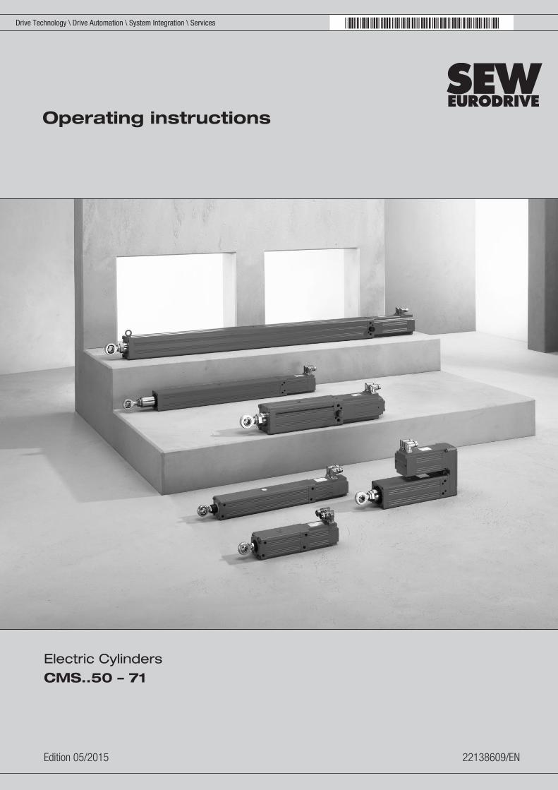
*22138609_0515*Drive Technology \ Drive Automation \ System Integration \ Services
Operating instructions
Electric CylindersCMS..50 – 71
Edition 05/2015 22138609/EN
SEW-EURODRIVE—Driving the world
Contents
Operating instructions – CMS..50 – 71 3
Contents1 General information .................................................................................................................. 5
1.1 About this documentation ............................................................................................... 51.2 Structure of the safety notes .......................................................................................... 51.3 Rights to claim under limited warranty ........................................................................... 71.4 Exclusion of liability ........................................................................................................ 71.5 Copyright notice ............................................................................................................. 7
2 Safety notes ............................................................................................................................... 82.1 Preliminary information .................................................................................................. 82.2 General information ........................................................................................................ 82.3 Target group ................................................................................................................... 92.4 Designated use .............................................................................................................. 92.5 Other applicable documentation .................................................................................... 92.6 Transport/storage ........................................................................................................... 92.7 Installation ................................................................................................................... 102.8 Electrical connection .................................................................................................... 102.9 Startup/operation .......................................................................................................... 112.10 Safety notes on the motor ............................................................................................ 12
3 Electric cylinder design .......................................................................................................... 133.1 Designs ........................................................................................................................ 133.2 "Generation" characteristic ........................................................................................... 133.3 Sizes ............................................................................................................................ 143.4 CMS.. standard electric cylinders - Nameplate ............................................................ 153.5 CMS.. standard electric cylinders - Type designation .................................................. 163.6 Sample serial number of an electric cylinder ............................................................... 163.7 Designs and options for the CMS.. electric cylinders ................................................... 173.8 Mounting Positions ....................................................................................................... 193.9 Standards ..................................................................................................................... 19
4 Mechanical installation ........................................................................................................... 204.1 Before you start ............................................................................................................ 204.2 Required tools/resources ............................................................................................. 204.3 Storage conditions ....................................................................................................... 204.4 Operating temperatures ............................................................................................... 204.5 Installing the electric cylinder ....................................................................................... 214.6 Installation situation at the customer ............................................................................ 224.7 Mechanical stroke limiting ............................................................................................ 334.8 VR forced cooling fan ................................................................................................... 34
5 Electrical Installation............................................................................................................... 355.1 Additional regulations ................................................................................................... 355.2 Compulsory use of the wiring diagrams ....................................................................... 355.3 Wiring notes ................................................................................................................. 365.4 Notes regarding the connection of the power and signal cables via the connector
system ......................................................................................................................... 365.5 Connecting the motor and the encoder system via plug connector SM./ SB. .............. 38
2213
8609
/EN
– 0
5/20
15
Contents
Operating instructions – CMS..50 – 714
5.6 Connecting the motor and the encoder system via KK/KKS terminal box toCMSMB50/63/71 .......................................................................................................... 46
5.7 Options ......................................................................................................................... 51
6 Startup...................................................................................................................................... 536.1 Important notes on startup ........................................................................................... 536.2 Before startup ............................................................................................................... 54
7 Inspection/maintenance.......................................................................................................... 557.1 General maintenance work .......................................................................................... 557.2 Lubrication of the threaded spindle CMS50/CMS71 .................................................... 567.3 Lubricant for recirculating ball screws and planetary roller screw drives for CMS50 and
CMS71 ........................................................................................................................ 587.4 Relubrication interval .................................................................................................... 597.5 Lubricator – only for CMS71 ........................................................................................ 617.6 Sealing air .................................................................................................................... 627.7 Filter ventilation CMS71 ............................................................................................... 637.8 Liquid cooling ............................................................................................................... 637.9 Oil bath lubrication of CMSB50/63/71, CMSMB50/63/71 ............................................. 667.10 Size CMSB50/63/71 and CMSMB50/63/71 with oil bath lubrication ............................ 667.11 Size CMS50 and CMS71 with grease lubrication ........................................................ 677.12 Service life .................................................................................................................... 67
8 Technical data.......................................................................................................................... 688.1 Key to the data tables .................................................................................................. 688.2 General features .......................................................................................................... 698.3 CMS50 ......................................................................................................................... 698.4 CMSB50, CSMB50 ...................................................................................................... 718.5 CMSB63, CMSMB63 ................................................................................................... 818.6 CMSB71, CMSMB71 ................................................................................................... 898.7 CMS71L ....................................................................................................................... 998.8 Motors with forced cooling fan ................................................................................... 1018.9 Brakes BP/BK/BS ....................................................................................................... 1048.10 Technical data of BP brakes ...................................................................................... 1058.11 Technical data of BK brakes ...................................................................................... 1078.12 Technical data BS brake ............................................................................................ 1098.13 Encoder ...................................................................................................................... 111
9 Malfunctions .......................................................................................................................... 1139.1 Notes .......................................................................................................................... 1139.2 Customer service ....................................................................................................... 1149.3 Standard electric cylinder malfunctions ...................................................................... 1149.4 Inverter malfunctions .................................................................................................. 1159.5 Brake malfunctions ..................................................................................................... 1159.6 Disposal ..................................................................................................................... 115
Index ....................................................................................................................................... 116
10 Address list ............................................................................................................................ 118 2213
8609
/EN
– 0
5/20
15
1General informationAbout this documentation
Operating instructions – CMS..50 – 71 5
1 General information1.1 About this documentation
This documentation is an integral part of the product. The documentation is intendedfor all employees who perform assembly, installation, startup, and service work on theproduct.Make sure this documentation is accessible and legible. Ensure that persons respon-sible for the machinery and its operation as well as persons who work on the deviceindependently have read through the documentation carefully and understood it. If youare unclear about any of the information in this documentation or require further infor-mation, contact SEW‑EURODRIVE.
1.2 Structure of the safety notes1.2.1 Meaning of signal words
The following table shows the grading and meaning of the signal words for safetynotes.
Signal word Meaning Consequences if disregarded
DANGER Imminent hazard Severe or fatal injuries.
WARNING Possible dangerous situation Severe or fatal injuries.
CAUTION Possible dangerous situation Minor injuries
NOTICE Possible damage to property Damage to the drive system or itsenvironment.
INFORMATION Useful information or tip: Simplifieshandling of the drive system.
2213
8609
/EN
– 0
5/20
15
1 General informationStructure of the safety notes
Operating instructions – CMS..50 – 716
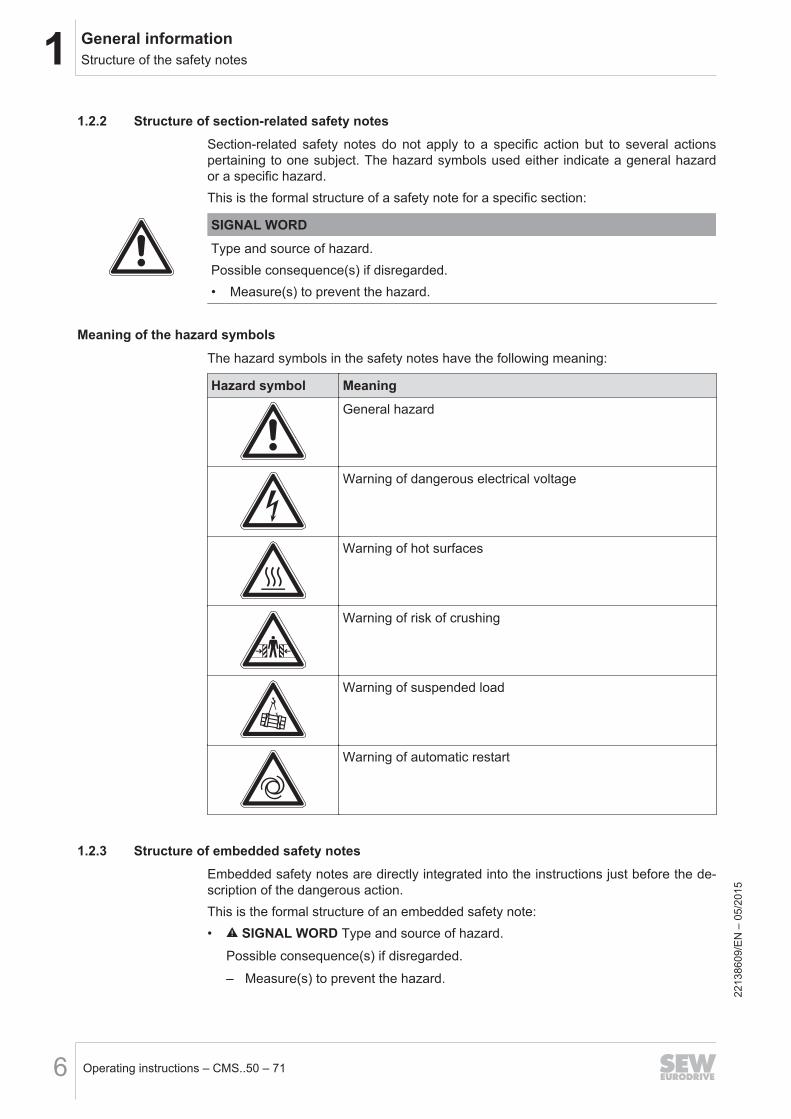
1.2.2 Structure of section-related safety notesSection-related safety notes do not apply to a specific action but to several actionspertaining to one subject. The hazard symbols used either indicate a general hazardor a specific hazard.This is the formal structure of a safety note for a specific section:
SIGNAL WORD
Type and source of hazard.Possible consequence(s) if disregarded.• Measure(s) to prevent the hazard.
Meaning of the hazard symbols
The hazard symbols in the safety notes have the following meaning:
Hazard symbol Meaning
General hazard
Warning of dangerous electrical voltage
Warning of hot surfaces
Warning of risk of crushing
Warning of suspended load
Warning of automatic restart
1.2.3 Structure of embedded safety notesEmbedded safety notes are directly integrated into the instructions just before the de-scription of the dangerous action.This is the formal structure of an embedded safety note:• SIGNAL WORD Type and source of hazard.
Possible consequence(s) if disregarded.
– Measure(s) to prevent the hazard.
2213
8609
/EN
– 0
5/20
15
1General informationRights to claim under limited warranty
Operating instructions – CMS..50 – 71 7
1.3 Rights to claim under limited warrantyRead the information in this documentation. This is essential for fault-free operationand fulfillment of any rights to claim under limited warranty. Read the documentationbefore you start working with the unit!
1.4 Exclusion of liabilityRead the information in this documentation, otherwise safe operation is impossible.You must comply with the information contained in this documentation to achieve thespecified product characteristics and performance features. SEW‑EURODRIVE as-sumes no liability for injury to persons or damage to equipment or property resultingfrom non-observance of these operating instructions. In such cases,SEW‑EURODRIVE assumes no liability for defects.
1.5 Copyright notice© 2015 SEW‑EURODRIVE. All rights reserved.Unauthorized reproduction, modification, distribution or any other use of the whole orany part of this documentation is strictly prohibited.
2213
8609
/EN
– 0
5/20
15
2 Safety notesPreliminary information
Operating instructions – CMS..50 – 718
2 Safety notesThe following basic safety notes must be read carefully to prevent injury to personsand damage to property. The user must ensure that the basic safety notes are readand observed. Ensure that persons responsible for the system and its operation, aswell as persons who work independently on the unit, have read through the operatinginstructions carefully and understood them. If you are unclear about any of the infor-mation in this documentation, or if you require further information, contactSEW‑EURODRIVE.
2.1 Preliminary informationThe following safety notes are concerned with the use of CMS.. standard/modularelectric cylinders.Also observe the supplementary safety notes in the individual sections of this docu-mentation.
2.2 General information
WARNINGDanger of fatal injury during operation as the motors and gearmotors can have live,bare (in the event of open connectors/terminal boxes) and movable or rotating partsas well as hot surfaces.
Severe or fatal injuries.
• All work related to transport, storage, installation, assembly, connection, startup,maintenance and repair may only be carried out by qualified personnel.
• For transport, storage, installation, assembly, connection, startup, maintenanceand repair it is important that you adhere to the information in the following docu-ments:– Warning and safety signs on the motor/gearmotor– All the project planning documents, startup instructions and wiring diagrams
related to the drive– System-specific regulations and requirements– National/regional safety and accident prevention regulations.
• Never install damaged products.
• Never operate or energize the unit without the necessary protection covers orhousing.
• Use the unit only for its intended purpose.
• Make sure the unit is installed and operated properly.
This documentation provides additional information.
2213
8609
/EN
– 0
5/20
15
2Safety notesTarget group
Operating instructions – CMS..50 – 71 9
2.3 Target groupAny mechanical work may only be performed by adequately qualified personnel.Qualified personnel in the context of this documentation are persons familiar with thedesign, mechanical installation, troubleshooting and servicing of the product who pos-sess the following qualifications:• Training in mechanical engineering, e.g. as a mechanic or mechatronics technician
(final examinations must have been passed).• They are familiar with these operating instructions.Any electronic work may only be performed by adequately qualified electricians. Quali-fied electricians in the context of this documentation are persons familiar with electricalinstallation, startup, troubleshooting and servicing of the product who possess the fol-lowing qualifications:• Training in electrical engineering, e.g. as an electrician, electronics or mechatron-
ics technician (final examinations must have been passed).• They are familiar with these operating instructions.All work in the areas of transportation, storage, operation and waste disposal must becarried out by persons who are trained appropriately.All qualified personnel must wear appropriate protective clothing.
2.4 Designated useCMS.. electric cylinders are drive motors designed for use in industrial and commer-cial systems. If motors are subject to loads other than those permitted, or if they areused areas of application other than industrial and commercial systems, you must firstcontact SEW‑EURODRIVE.The CMS.. electric cylinders meet the requirements of EC directive 2006/95/EC (lowvoltage directive). Do not take the unit into operation until you have established thatthe end product complies with the EC Machinery Directive 2006/42/EC.Observe the technical data and information on the connection requirements as provi-ded on the nameplate and in the documentation.
2.5 Other applicable documentationThe following publications and documents have to be observed as well:
• Wiring diagrams available from SEW‑EURODRIVE
• Catalog "Electric Cylinders CMS..50 – 71"• "CMP40 – 112, CMPZ71 – CMPZ100 Synchronous Servomotors" operating in-
structions• "Synchronous Servomotors" catalog
2.6 Transport/storageInspect the shipment for damage as soon as you receive the delivery. Inform the ship-ping company immediately about any damage. It may be necessary to suspendstartup.
2213
8609
/EN
– 0
5/20
15
2 Safety notesInstallation
Operating instructions – CMS..50 – 7110
Tighten the eyebolts securely. They are designed for the weight of the CMS.. electriccylinder only; do not attach any additional loads.The installed lifting eyebolts are in accordance with DIN 580. The loads and regula-tions specified in that document must always be observed. If the CMS.. electric cylin-der is equipped with two lifting eyes or eyebolts, then both of these should be used fortransportation. In this case, the tension force vector of the slings must not exceed a45° angle in accordance with DIN 580.Use suitable, sufficiently rated handling equipment if necessary. Reattach these in thecase of further transportation.Store the CMS.. electric cylinder in a dry, dust-free environment if it is not to be instal-led straight away. The CMS.. electric cylinder can be stored for one year without re-quiring any special measures before startup.
2.7 InstallationAlso adhere to the information in chapter "Mechanical installation (→ 2 20)" and"Electrical installation".The units must be installed and cooled according to the regulations and specificationsin the corresponding documentation.Protect the electric cylinders from excessive strain. Ensure that components are notdamaged, particularly during transportation and handling.The following applications are prohibited unless explicitly permitted:• Use in potentially explosive atmospheres• Use in areas exposed to harmful oils, acids, gases, vapors, dust, radiation, etc.
2.8 Electrical connectionAll work may only be carried out by qualified personnel. During work, the low-voltagemachine must be at standstill, de-energized, and safeguarded against accidental re-start. This also applies to auxiliary circuits (e.g. anti-condensation heating or forcedcooling fan).Check whether the unit is de-energized.Exceeding the tolerances in EN 60034-1 (VDE 0530, part 1) – voltage + 5%, frequen-cy + 2%, curve shape, symmetry – increases the heating and influences electromag-netic compatibility. Also comply with EN 50110 (where necessary, observe other appli-cable national regulations, such as DIN VDE 0105 for Germany).Observe the wiring information and differing data on the nameplate as well as the wir-ing diagram provided with the motor.The connection must be a permanently secure electrical connection (no protrudingwire ends):• Use the corresponding cable end equipment.• Establish a secure protective earth connection.
2213
8609
/EN
– 0
5/20
15
2Safety notesStartup/operation
Operating instructions – CMS..50 – 71 11
When the motor is connected, the distances to non-insulated and live parts must notbe shorter than the minimum values according to IEC 60664 and national regulations.With low voltage, the distances should be no shorter than the following values, in com-pliance with IEC 60664:
Nominal voltage VN Distance
≤ 500 V 3 mm
≤ 690 V 5.5 mm
The connection box must be free from foreign objects, dirt and humidity. Unused cableentry openings and the box itself must be closed so that they are dust- and water-proof. Secure the key for test mode without output elements. When operating low-volt-age machines with brakes, check that the brake is functioning correctly before startup.
2.9 Startup/operationWhenever changes to normal operation occur, such as increased temperatures, noise,vibrations, etc., you should determine the cause. Consult the manufacturer if required.Never deactivate protection devices, even in test mode. Switch off the motor/CMS..electric cylinder if you are not sure.Regularly clean air ducts in case of a high degree of pollution.
2.9.1 Surface temperature during operationServomotors/CMS.. electric cylinders get very hot during operation.Touching the servomotor/CMS.. electric cylinder when it has not been cooled can re-sult in burns. The servomotor can have a surface temperature of more than 100 °Cduring operation.Never touch the servomotor/CMS.. electric cylinder during operation or in the cooldown phase after it has been switched off.
2213
8609
/EN
– 0
5/20
15
2 Safety notesSafety notes on the motor
Operating instructions – CMS..50 – 7112
2.10 Safety notes on the motor
CAUTIONSafety notes or signs can become dirty or illegible over time.
Risk of injury due to illegible symbols.
• Always make sure that safety, warning, and operating notes are legible.
• Replace damaged safety notes and signs.
The safety notes on the motor must be observed. They have the following meaning:
Safety note Meaning
Do not unplug the signal plug connector while it is ener-gized!
–
17123852
–
–
For motors with BK brake: It is essential that you observe the correct polarity of BKbrake supply. Check the polarity when replacing the brake.
2213
8609
/EN
– 0
5/20
15
3Electric cylinder designDesigns
Operating instructions – CMS..50 – 71 13
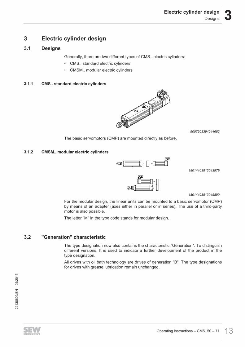
3 Electric cylinder design3.1 Designs
Generally, there are two different types of CMS.. electric cylinders:• CMS.. standard electric cylinders• CMSM.. modular electric cylinders
3.1.1 CMS.. standard electric cylinders
9007203394044683
The basic servomotors (CMP) are mounted directly as before.
3.1.2 CMSM.. modular electric cylinders
18014403813043979
18014403813045899
For the modular design, the linear units can be mounted to a basic servomotor (CMP)by means of an adapter (axes either in parallel or in series). The use of a third-partymotor is also possible.The letter "M" in the type code stands for modular design.
3.2 "Generation" characteristicThe type designation now also contains the characteristic "Generation". To distinguishdifferent versions. It is used to indicate a further development of the product in thetype designation.All drives with oil bath technology are drives of generation "B". The type designationsfor drives with grease lubrication remain unchanged.
2213
8609
/EN
– 0
5/20
15
3 Electric cylinder designSizes
Operating instructions – CMS..50 – 7114
3.3 SizesSEW‑EURODRIVE offers 4 product variants in 4 sizes:
• CMS50
• CMSB50/63/71• CMSMB50/63/71• CMS71
2213
8609
/EN
– 0
5/20
15
3Electric cylinder designCMS.. standard electric cylinders - Nameplate
Operating instructions – CMS..50 – 71 15
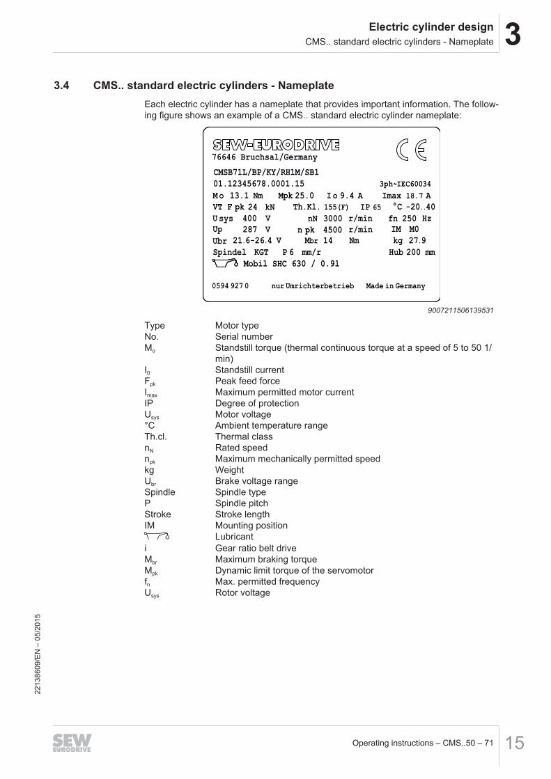
3.4 CMS.. standard electric cylinders - NameplateEach electric cylinder has a nameplate that provides important information. The follow-ing figure shows an example of a CMS.. standard electric cylinder nameplate:
76646 Bruchsal/Germany
3ph~IEC60034
CMSB71L/BP/KY/RH1M/SB1
01.12345678.0001.15
M o I o13.1 Nm 9.4 A Imax
nN 3000 r/min
IP 65
U sys 400
Th.Kl.
Up V21.6-26.4 V Mbr 14 Nm
Spindel
IM
kg 27.9
0594 927 0 nur Umrichterbetrieb Made in Germany
V
287 r/min M0
Ubr
KGT P 6 mm/r Hub 200 mm
VT F pk 24 °C -20..40
Mobil SHC 630 / 0.9l
n pk 4500
kN
Mpk 25.0 18.7 A
155(F)
fn 250 Hz
9007211506139531
Type Motor typeNo. Serial numberMo Standstill torque (thermal continuous torque at a speed of 5 to 50 1/
min)I0 Standstill currentFpk Peak feed forceImax Maximum permitted motor currentIP Degree of protectionUsys Motor voltage°C Ambient temperature rangeTh.cl. Thermal classnN Rated speednpk Maximum mechanically permitted speedkg WeightUbr Brake voltage rangeSpindle Spindle typeP Spindle pitchStroke Stroke lengthIM Mounting position
Lubricanti Gear ratio belt driveMbr Maximum braking torqueMpk Dynamic limit torque of the servomotorfn Max. permitted frequencyUsys Rotor voltage
2213
8609
/EN
– 0
5/20
15
3 Electric cylinder designCMS.. standard electric cylinders - Type designation
Operating instructions – CMS..50 – 7116
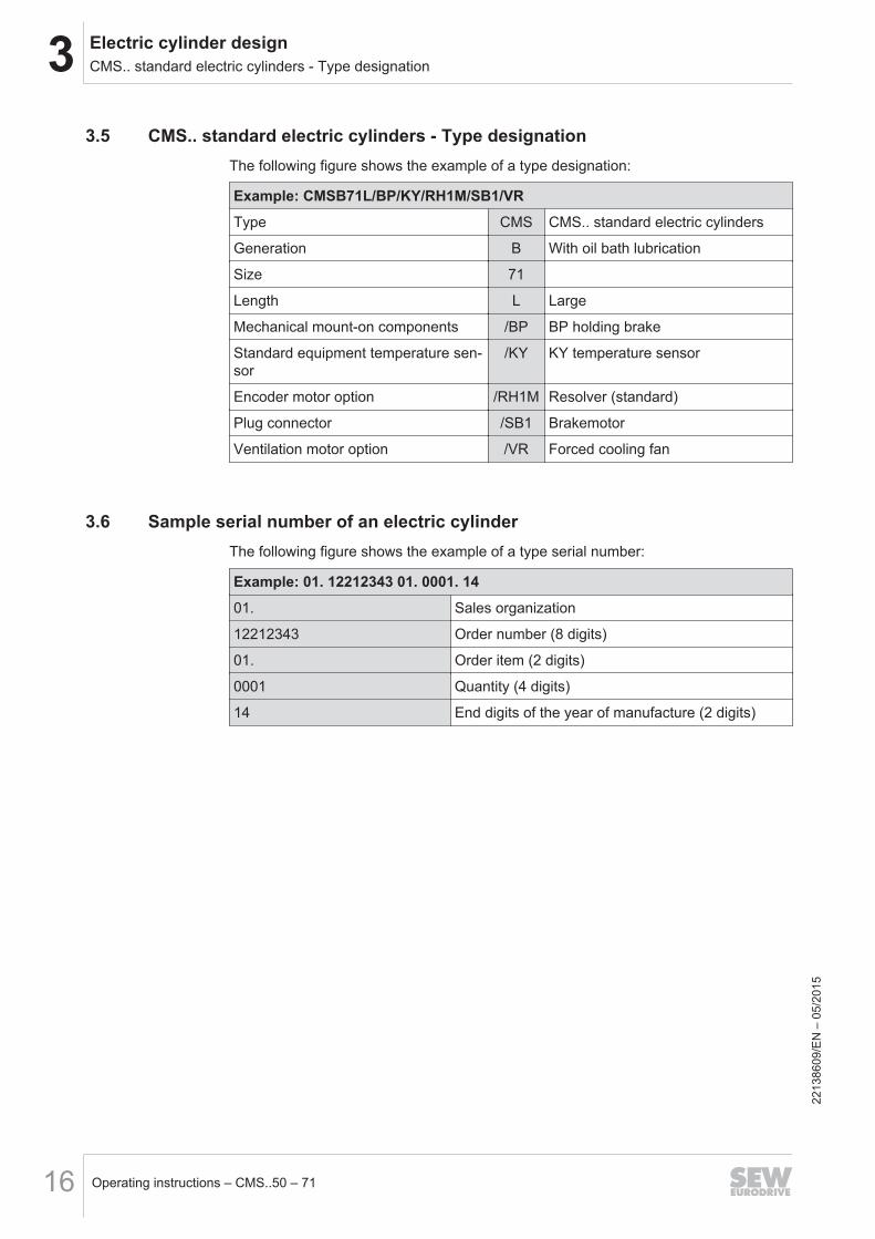
3.5 CMS.. standard electric cylinders - Type designationThe following figure shows the example of a type designation:
Example: CMSB71L/BP/KY/RH1M/SB1/VR
Type CMS CMS.. standard electric cylinders
Generation B With oil bath lubrication
Size 71
Length L Large
Mechanical mount-on components /BP BP holding brake
Standard equipment temperature sen-sor
/KY KY temperature sensor
Encoder motor option /RH1M Resolver (standard)
Plug connector /SB1 Brakemotor
Ventilation motor option /VR Forced cooling fan
3.6 Sample serial number of an electric cylinderThe following figure shows the example of a type serial number:
Example: 01. 12212343 01. 0001. 14
01. Sales organization
12212343 Order number (8 digits)
01. Order item (2 digits)
0001 Quantity (4 digits)
14 End digits of the year of manufacture (2 digits)
2213
8609
/EN
– 0
5/20
15
3Electric cylinder designDesigns and options for the CMS.. electric cylinders
Operating instructions – CMS..50 – 71 17
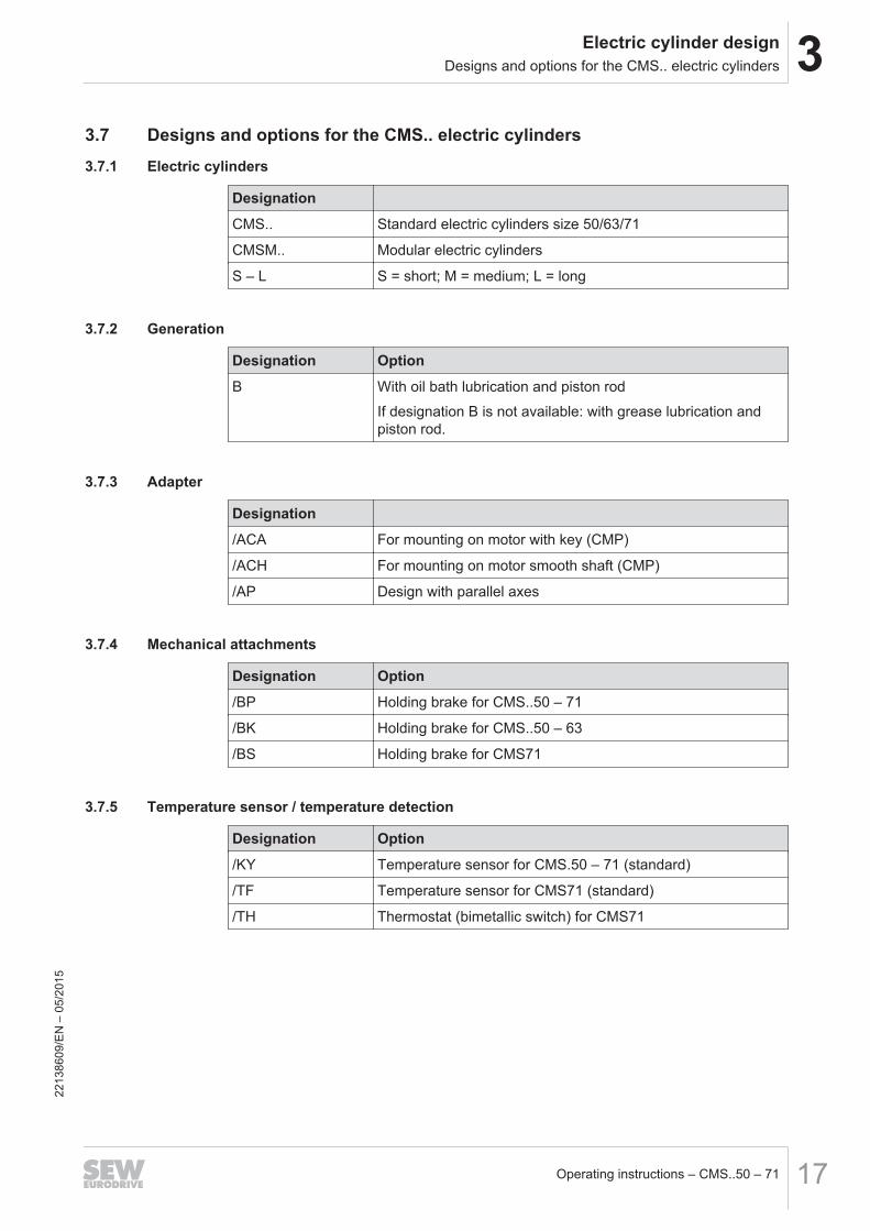
3.7 Designs and options for the CMS.. electric cylinders3.7.1 Electric cylinders
Designation
CMS.. Standard electric cylinders size 50/63/71
CMSM.. Modular electric cylinders
S – L S = short; M = medium; L = long
3.7.2 Generation
Designation Option
B With oil bath lubrication and piston rod
If designation B is not available: with grease lubrication andpiston rod.
3.7.3 Adapter
Designation
/ACA For mounting on motor with key (CMP)
/ACH For mounting on motor smooth shaft (CMP)
/AP Design with parallel axes
3.7.4 Mechanical attachments
Designation Option
/BP Holding brake for CMS..50 – 71
/BK Holding brake for CMS..50 – 63
/BS Holding brake for CMS71
3.7.5 Temperature sensor / temperature detection
Designation Option
/KY Temperature sensor for CMS.50 – 71 (standard)
/TF Temperature sensor for CMS71 (standard)
/TH Thermostat (bimetallic switch) for CMS71
2213
8609
/EN
– 0
5/20
15

3 Electric cylinder designDesigns and options for the CMS.. electric cylinders
Operating instructions – CMS..50 – 7118
3.7.6 Encoders
Designation Option
/RH1M Resolver (standard)
/ES1H Single-turn Hiperface® encoder, spread shaft, high resolutionfor CMS50/71, CMSB63
/AS1H Multi-turn Hiperface® encoder, spread shaft, high resolution forCMS50/71, CMSB63
/AK0H Multi-turn Hiperface® encoder, cone shaft, for CMS50/71,CMSB50/63/71
/EK1H Single-turn Hiperface® encoder, cone shaft, high resolution forCMSB50/71, CMSB631) , CMS711)
/AK1H Multi-turn Hiperface® encoder, cone shaft, high resolution forMSB50/71, CMSB631), CMS711)
1) in preparation
3.7.7 Connection options
Designation Option
/SM1 M23 motor plug connector, socket on motor end only, plugga-ble motor and encoder cables (standard)
/SB1 M23 brakemotor plug connector, socket on motor end only,pluggable motor and encoder cables (standard)
3.7.8 Ventilation
Designation Option
/VR Forced cooling fan
2213
8609
/EN
– 0
5/20
15
3Electric cylinder designMounting Positions
Operating instructions – CMS..50 – 71 19
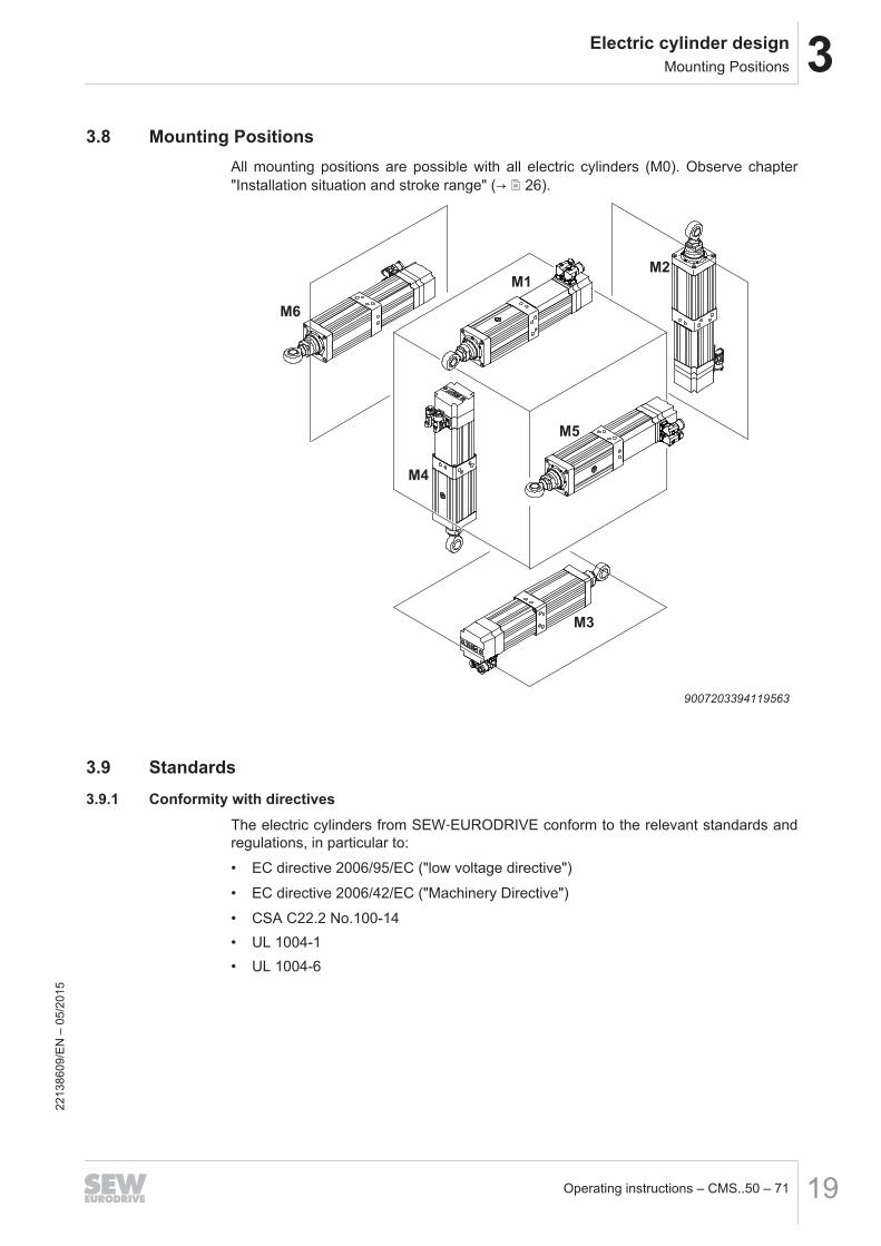
3.8 Mounting PositionsAll mounting positions are possible with all electric cylinders (M0). Observe chapter"Installation situation and stroke range" (→ 2 26).
M1
M4
M3
M5
M6
M2
9007203394119563
3.9 Standards3.9.1 Conformity with directives
The electric cylinders from SEW‑EURODRIVE conform to the relevant standards andregulations, in particular to:
• EC directive 2006/95/EC ("low voltage directive")
• EC directive 2006/42/EC ("Machinery Directive")
• CSA C22.2 No.100-14• UL 1004-1• UL 1004-6
2213
8609
/EN
– 0
5/20
15
4 Mechanical installationBefore you start
Operating instructions – CMS..50 – 7120
4 Mechanical installation4.1 Before you start
Install the electric cylinder only if the following conditions are met:
• The electric cylinder must be undamaged (no damage caused by shipping or stor-age).
• The specifications on the nameplate of the electric cylinder correspond to the sup-ply system or the output voltage of the servo inverter.
• The ambient temperature is between -20 °C and +40 °C.• The installation altitude must be no higher than 1000 m above sea level, otherwise
the drive must be designed to meet the special ambient conditions.• The surrounding area is free from oils, acids, gases, vapors, radiation, etc.
4.2 Required tools/resources• Standard tools• Belt tension device if necessary
4.3 Storage conditionsThe CMS.. electric cylinders are treated with an corrosion protection as standard.The motor parts are protected against corrosion for two years when stored in unop-ened original packaging (with Vario lubrication system one year → battery life).Note the following storage conditions:
• Store CMS.. electric cylinders indoors
• Keep the storage location clean and dry
• The storage temperature should be between -10 °C and +70 °C• The humidity must not exceed 95%• Original packaging must not be damaged
4.4 Operating temperaturesThe electric cylinders are designed for use in a temperature range between -20 °Cand +40 °C.CMS71 with BS brake must only be used in a temperature range of -5°C to 40°C.CMSB50/63/71 and CMSMB50/63/71: If you use the electric cylinder with the pistonrod pointing downwards, observe chapter "Installation situation and strokerange" (→ 2 26).Contact SEW‑EURODRIVE if the motors are operated outside this temperature range.
2213
8609
/EN
– 0
5/20
15
4Mechanical installationInstalling the electric cylinder
Operating instructions – CMS..50 – 71 21
4.5 Installing the electric cylinder
WARNINGRisk of unexpected restart of the drive.
Severe or fatal injuries or damage to property.
• De-energize the electric cylinder before you start working on the unit.
• Safeguard the electric cylinder against unintentional restart.
CAUTIONThe electric cylinder can get very hot during operation.
Risk of burns.
• Never touch the electric cylinder during operation or in the cool down phase onceit has been switched off.
WARNINGWith lifting applications, make sure that the holding torque M4, 100°C of the brake isbigger than the corresponding load torque of the application.
Severe or fatal injuries.
• Observe the project planning guidelines.
• The spindles that are used are not self-locking.
• See chapter "Possible maximum holding forces" (→ 2 104).
NOTICEImproper mounting may result in damages to the electric cylinder.
Possible damage to property.
• Observe the following notes.
• Mount the electric cylinder only on a level, vibration-free and torsionally rigid sup-port structure.
• Make sure the customer's counter-bearing is unobstructed and can move freely.
• Carefully align the electric cylinder and the driven machine to avoid placing any un-acceptable strain on the spindle (observe permissible axial load data).
• Make sure that the electric cylinder is not subject to overhung loads and bendingmoments.
• Do not jolt or hammer the spindle end.
• Protect the bellows, the threaded spindle and the piston rod against mechanicaldamage.
• Mount the electric cylinder in the specified mounting position only.• Make sure that the warm exhaust air of other devices is not sucked in.
4.5.1 Installation in damp locations or outdoors
• Try to arrange the motor and encoder connection so that the connector cables donot point upwards.
2213
8609
/EN
– 0
5/20
15
4 Mechanical installationInstallation situation at the customer
Operating instructions – CMS..50 – 7122
• Clean the sealing surfaces of the connector (motor or encoder connection) beforereassembly.
• Replace any brittle seals.
• If necessary, restore the anticorrosive paint coat.• Check that the degree of protection is maintained.• Attach covers (canopy) for installation in the open.
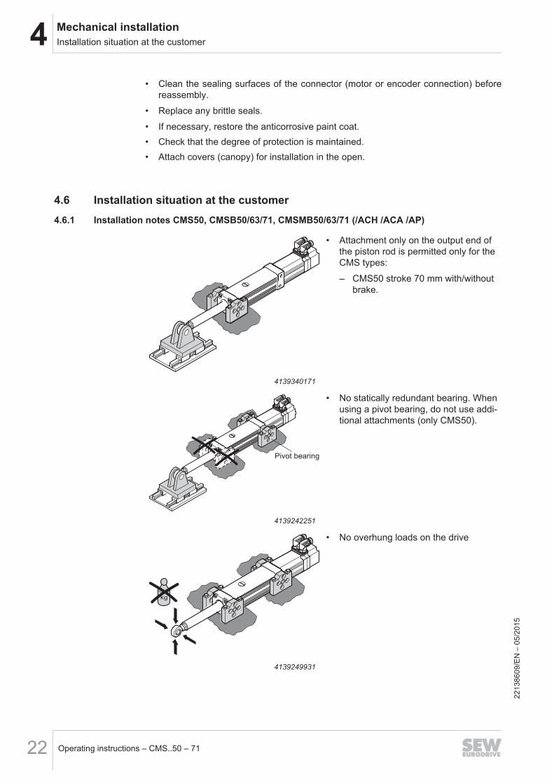
4.6 Installation situation at the customer4.6.1 Installation notes CMS50, CMSB50/63/71, CMSMB50/63/71 (/ACH /ACA /AP)
4139340171
• Attachment only on the output end ofthe piston rod is permitted only for theCMS types:
– CMS50 stroke 70 mm with/withoutbrake.
Pivot bearing
4139242251
• No statically redundant bearing. Whenusing a pivot bearing, do not use addi-tional attachments (only CMS50).
4139249931
• No overhung loads on the drive
2213
8609
/EN
– 0
5/20
15
4Mechanical installationInstallation situation at the customer
Operating instructions – CMS..50 – 71 23
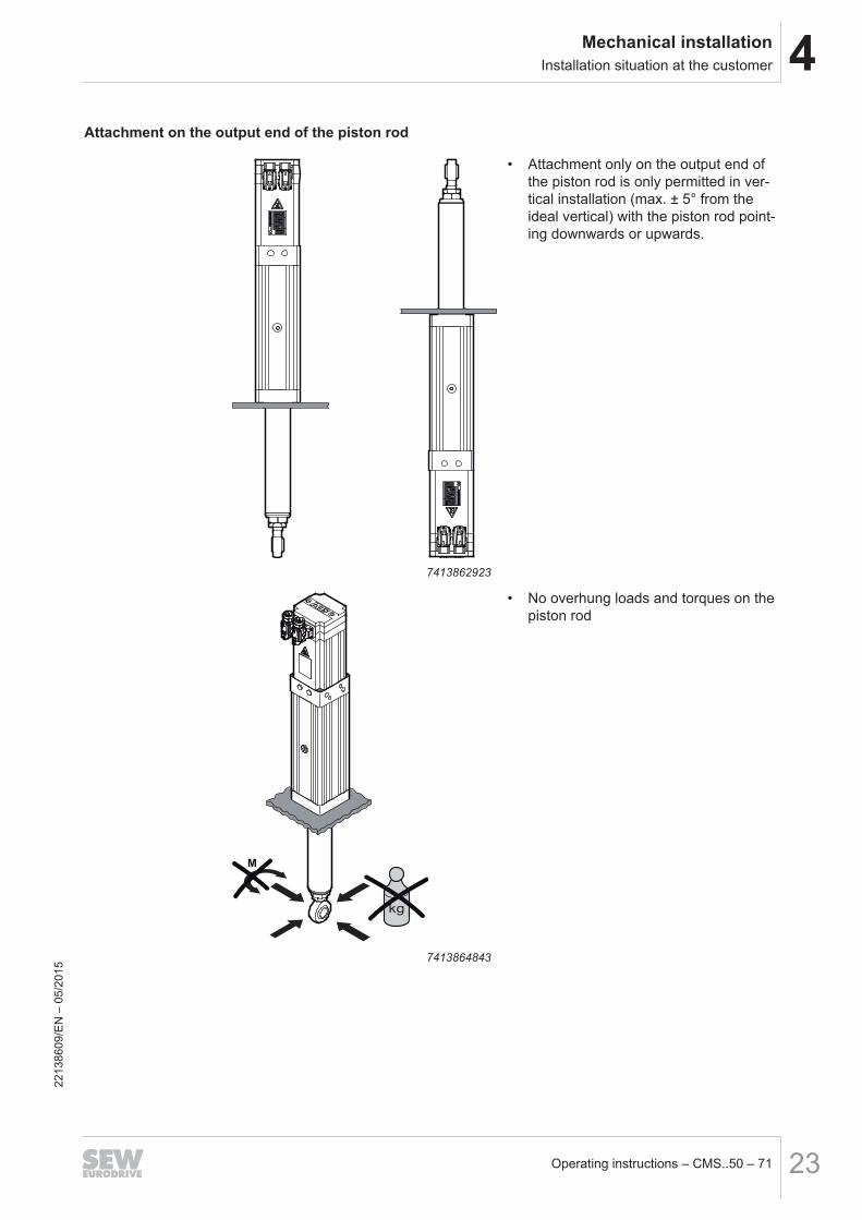
Attachment on the output end of the piston rod
7413862923
• Attachment only on the output end ofthe piston rod is only permitted in ver-tical installation (max. ± 5° from theideal vertical) with the piston rod point-ing downwards or upwards.
M
7413864843
• No overhung loads and torques on thepiston rod
2213
8609
/EN
– 0
5/20
15
4 Mechanical installationInstallation situation at the customer
Operating instructions – CMS..50 – 7124
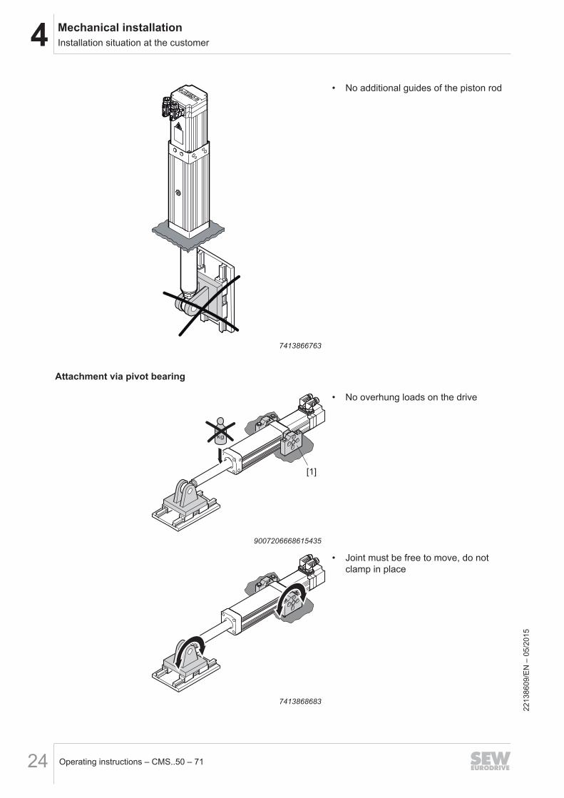
7413866763
• No additional guides of the piston rod
Attachment via pivot bearing
[1]
9007206668615435
• No overhung loads on the drive
7413868683
• Joint must be free to move, do notclamp in place
2213
8609
/EN
– 0
5/20
15
4Mechanical installationInstallation situation at the customer
Operating instructions – CMS..50 – 71 25
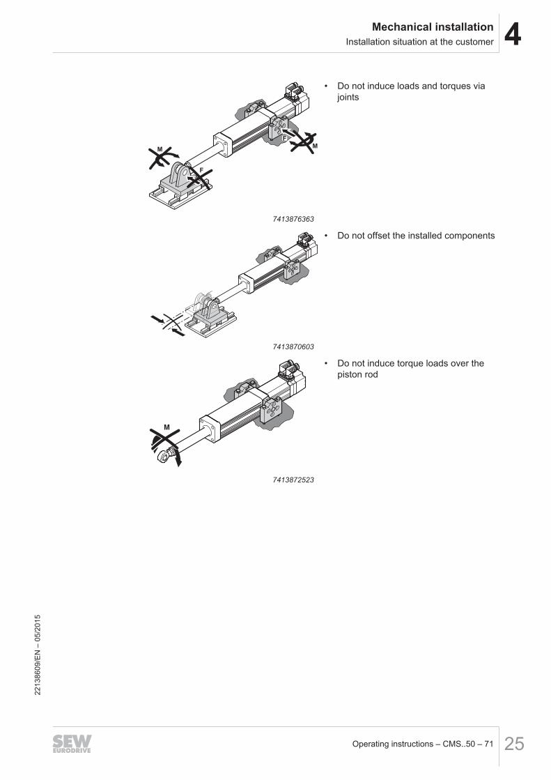
M
F
F
M
7413876363
• Do not induce loads and torques viajoints
7413870603
• Do not offset the installed components
M
7413872523
• Do not induce torque loads over thepiston rod
2213
8609
/EN
– 0
5/20
15
4 Mechanical installationInstallation situation at the customer
Operating instructions – CMS..50 – 7126
4.6.2 Installation situation and stroke range CMSB50/63/71, CMSMB50/63/71
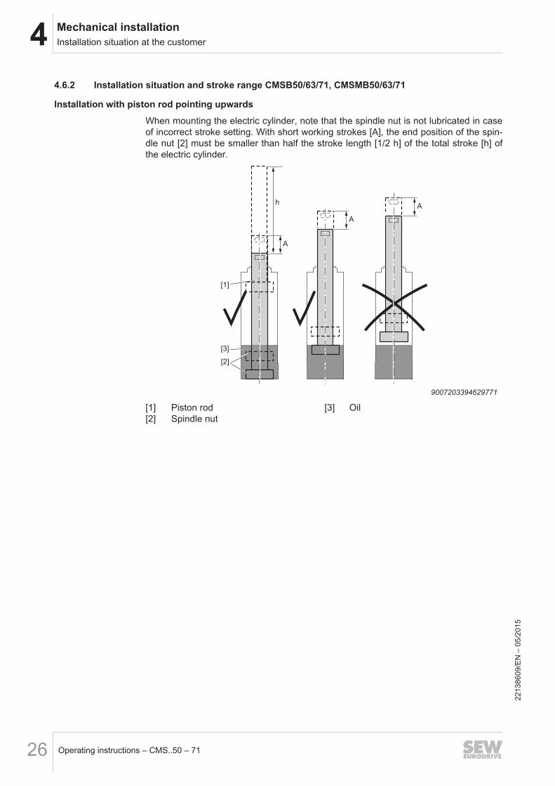
Installation with piston rod pointing upwards
When mounting the electric cylinder, note that the spindle nut is not lubricated in caseof incorrect stroke setting. With short working strokes [A], the end position of the spin-dle nut [2] must be smaller than half the stroke length [1/2 h] of the total stroke [h] ofthe electric cylinder.
A
A
A
[1]
[2]
[3]
h
9007203394629771
[1] Piston rod [3] Oil[2] Spindle nut
2213
8609
/EN
– 0
5/20
15
4Mechanical installationInstallation situation at the customer
Operating instructions – CMS..50 – 71 27
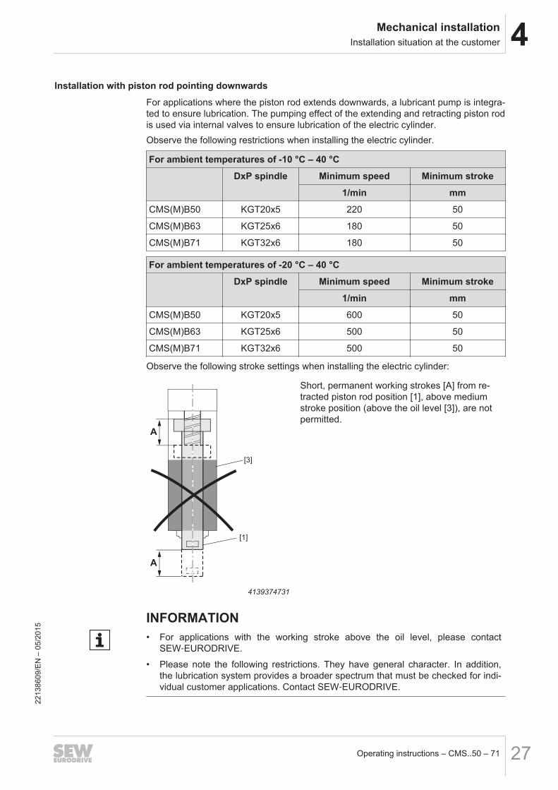
Installation with piston rod pointing downwards
For applications where the piston rod extends downwards, a lubricant pump is integra-ted to ensure lubrication. The pumping effect of the extending and retracting piston rodis used via internal valves to ensure lubrication of the electric cylinder.Observe the following restrictions when installing the electric cylinder.
For ambient temperatures of -10 °C – 40 °C
DxP spindle Minimum speed Minimum stroke
1/min mm
CMS(M)B50 KGT20x5 220 50
CMS(M)B63 KGT25x6 180 50
CMS(M)B71 KGT32x6 180 50
For ambient temperatures of -20 °C – 40 °C
DxP spindle Minimum speed Minimum stroke
1/min mm
CMS(M)B50 KGT20x5 600 50
CMS(M)B63 KGT25x6 500 50
CMS(M)B71 KGT32x6 500 50
Observe the following stroke settings when installing the electric cylinder:
A
A
[1]
[3]
4139374731
Short, permanent working strokes [A] from re-tracted piston rod position [1], above mediumstroke position (above the oil level [3]), are notpermitted.
INFORMATION• For applications with the working stroke above the oil level, please contact
SEW‑EURODRIVE.
• Please note the following restrictions. They have general character. In addition,the lubrication system provides a broader spectrum that must be checked for indi-vidual customer applications. Contact SEW‑EURODRIVE.
2213
8609
/EN
– 0
5/20
15
4 Mechanical installationInstallation situation at the customer
Operating instructions – CMS..50 – 7128
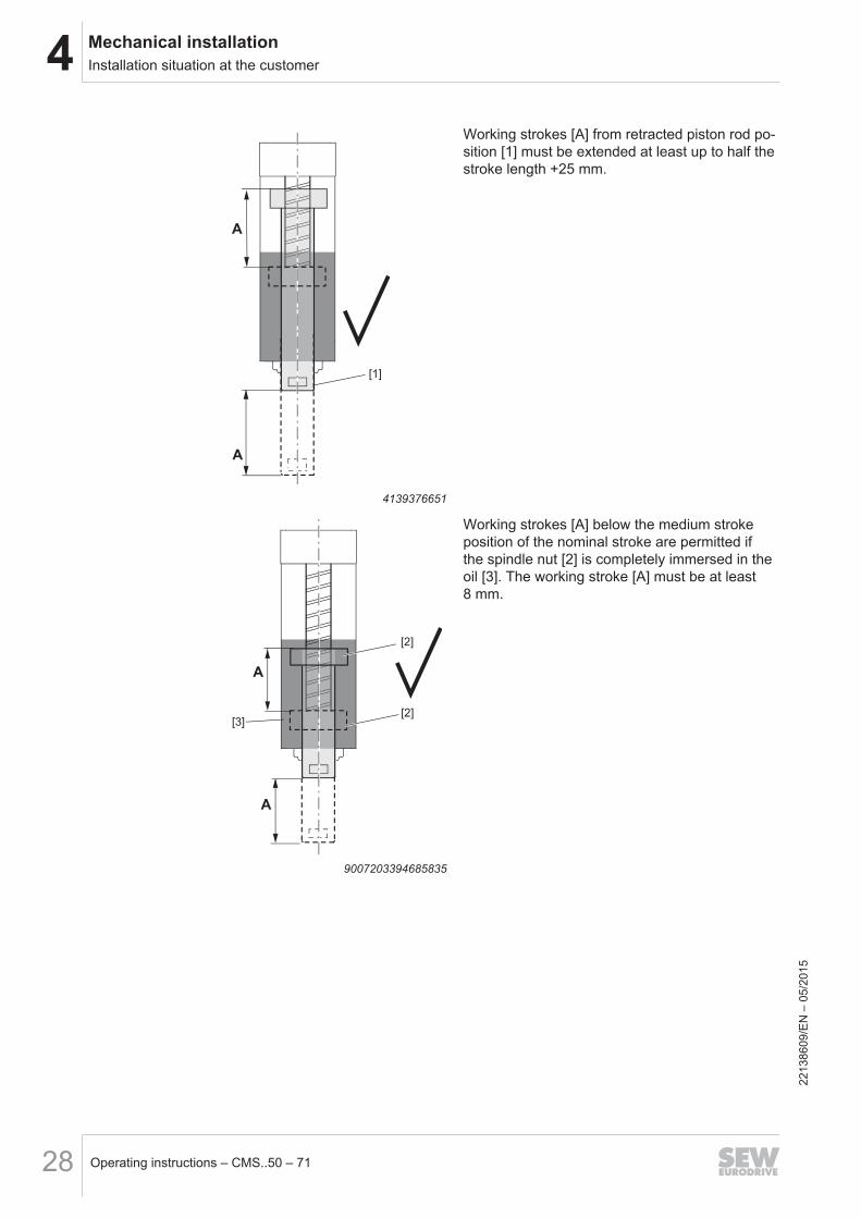
A
A
[1]
4139376651
Working strokes [A] from retracted piston rod po-sition [1] must be extended at least up to half thestroke length +25 mm.
A
[3][2]
[2]
A
9007203394685835
Working strokes [A] below the medium strokeposition of the nominal stroke are permitted ifthe spindle nut [2] is completely immersed in theoil [3]. The working stroke [A] must be at least8 mm.
2213
8609
/EN
– 0
5/20
15
4Mechanical installationInstallation situation at the customer
Operating instructions – CMS..50 – 71 29
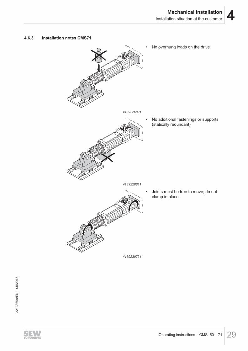
4.6.3 Installation notes CMS71
4139226891
• No overhung loads on the drive
4139228811
• No additional fastenings or supports(statically redundant)
4139230731
• Joints must be free to move; do notclamp in place.
2213
8609
/EN
– 0
5/20
15
4 Mechanical installationInstallation situation at the customer
Operating instructions – CMS..50 – 7130
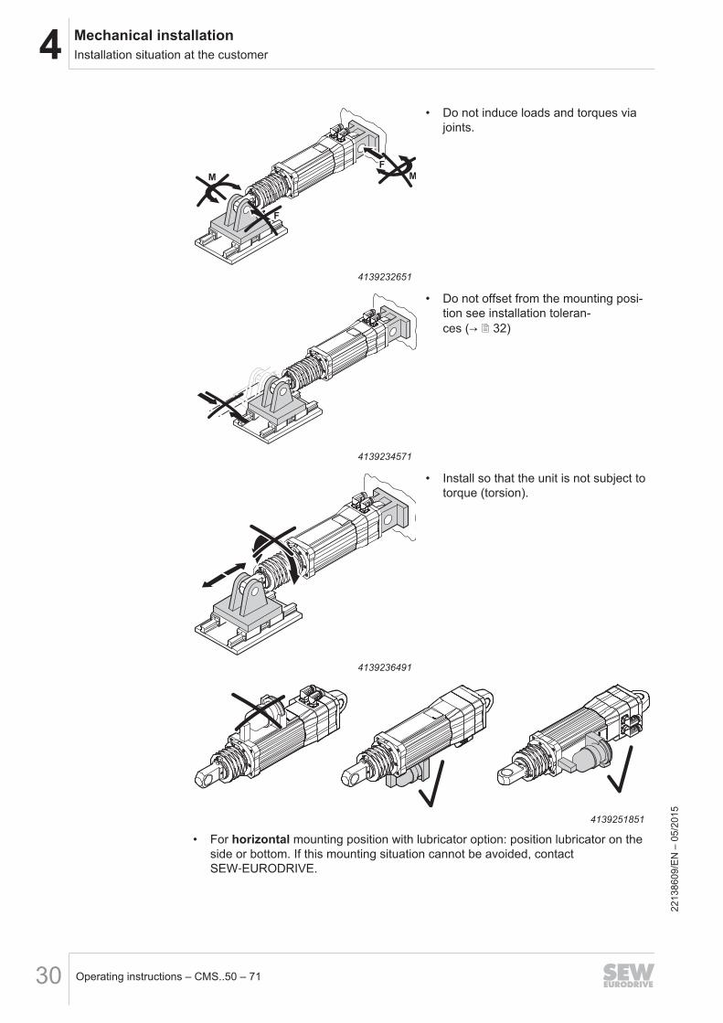
M M
F
F
4139232651
• Do not induce loads and torques viajoints.
4139234571
• Do not offset from the mounting posi-tion see installation toleran-ces (→ 2 32)
4139236491
• Install so that the unit is not subject totorque (torsion).
4139251851
• For horizontal mounting position with lubricator option: position lubricator on theside or bottom. If this mounting situation cannot be avoided, contactSEW‑EURODRIVE.
2213
8609
/EN
– 0
5/20
15
4Mechanical installationInstallation situation at the customer
Operating instructions – CMS..50 – 71 31
INFORMATIONFor the external installation of the lubricator (not directly on the motor) contactSEW‑EURODRIVE.
INFORMATIONIn case of high thermal capacity utilization, dissipated heat can affect the lubricantproperties.
4.6.4 Tolerances for mounting CMS50, CMSB50/63/71, CMSMB50/63/71 at the customer siteThe following figure describes the mounting situation for both mounting sides of thedrive.
D
P
K
3°
Rz 1
2
0.03
T AA
3°
0.1 A
0.1 A
7625893899
Type K D P T
CMS50 Ø 32 Ø 16 h7 21 +0.1 0.1 for stroke 70 – 300
CMSB50CMSMB50
Ø 40 Ø 16 h7 21 +0.10.1 for stroke 70 – 300
0.2 for stroke 400 – 600
CMSB63CMSMB63
Ø 50 Ø 20 h7 25 +0.10.1 for stroke 60 – 200
0.2 for stroke 400 – 600
CMSB71CMSMB71
Ø 60 Ø 25 h7 31 +0.1
0.1 for stroke 100 – 200
0.2 for stroke 400 – 600
0.3 for stroke 800 – 1200
2213
8609
/EN
– 0
5/20
15
4 Mechanical installationInstallation situation at the customer
Operating instructions – CMS..50 – 7132
4.6.5 Tolerances of the installation tolerances by the customer for CMS71The following figure describes the mounting situation for both mounting sides of thedrive.
Standard
30
+
0.1
0
[2]
[2]
Rz 1
2
0.03
0.05 B
A0.3
AB
[1]
Ø32h7
Rz 1
2
0.03
0.05 AØ32h7
30
+
0.1
0
7627359755
[1] Electric cylinders
[2] Customer-supplied parts
Please observe the following information:
• The max. axial offset between A – B is ±0.15 mm• The parts supplied by the customer must meet the requirements described above.• If mounting tolerances cannot be complied with, contact SEW‑EURODRIVE. An
electric cylinder with a cardan joint might fit the mounting situation.
Cardan joint
31
32 h7
30
+
0.1
0
3°
[2]
Rz 1
2
0.05 B
0.03
0.5 A
B
3°
7627361675
Please observe the following information:• The max. axial offset between A – B is ±0.5 mm
2213
8609
/EN
– 0
5/20
15
4Mechanical installationMechanical stroke limiting
Operating instructions – CMS..50 – 71 33
4.7 Mechanical stroke limiting
INFORMATIONThe customer must limit the stroke of the electric cylinder by providing for appropriatemeasures in the extended and retracted position, e.g. by using limit stops, buffers orshock absorbers.
The maximum permitted feed force of the electric cylinder must not be exceeded. Thatis why the mechanical limiting elements built-in by the customer must be able to ab-sorb the reactive forces and kinetic energy that is created when the end position stopsare reached. Soft, damping elements are necessary. Their purpose is to absorb theenergy and then limit the end position mechanically. As a rule, you should use buffersor shock absorbers that are dimensioned accordingly.
INFORMATIONThe rated stroke length (HCMS), e.g. CMS71L stroke 200 mm, is only available in limi-ted form for the customer application because safety distances (S) to the limit stopsrestrict the effective stroke (Heff).
M SS
A
THeff
18014402648797195
Heff Effective stroke A Distance between limit stopsHCMS Nominal stroke CMS T Partial widthS Safety distance M Weight
4.7.1 Calculating the effective strokeThe effective stroke can be calculated as follows:Heff = A - T - 2 x SorHeff = HCMS - 2 x S→ Heff < HCMS
2213
8609
/EN
– 0
5/20
15
4 Mechanical installationVR forced cooling fan
Operating instructions – CMS..50 – 7134
4.8 VR forced cooling fanThe electric cylinders CMS50, CMSB50/63/71, CMSMB50/63/71 can be equipped withan optional VR forced cooling fan.
INFORMATIONThe forced cooling fan can only be used up to a maximum oscillation and shock loadof 1 g.
4.8.1 Mechanical InstallationMounting the fan guard for the VR forced cooling fan:
Motor Screws Tightening torque
CMS50, CMSB50,CMSB63, CMSMB63
M4 × 8 self-tapping 4 Nm
CMSB71, CMSMB71 M6 × 20 4 Nm1)
1) Additional Loctite® thread locking compound
9007202158154123
4.8.2 Retrofit set for CMS50, CMSB50/63/71, CMSMB50/63/71Forced cooling fan retrofit sets are available for the motors of CMS50, CMSB50/63/71,CMSMB50/63/71.
INFORMATIONThe forced cooling fan retrofit set may only be mounted by staff authorized bySEW‑EURODRIVE.
INFORMATIONBefore the forced cooling fan is retrofitted, make sure that the previously used motorplug connector/cables also are approved for the higher current consumption after theretrofit.
For information on the retrofit set, refer to the "Synchronous Servomotors" catalog.
2213
8609
/EN
– 0
5/20
15
5Electrical InstallationAdditional regulations
Operating instructions – CMS..50 – 71 35
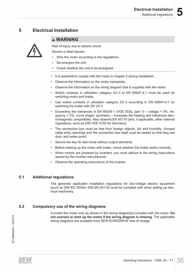
5 Electrical Installation
WARNINGRisk of injury due to electric shock.
Severe or fatal injuries.
• Wire the motor according to the regulations.
• De-energize the unit.
• Check whether the unit is de-energized.
• It is essential to comply with the notes in chapter 2 during installation.
• Observe the information on the motor nameplate.
• Observe the information on the wiring diagram that is supplied with the motor.
• Switch contacts in utilization category AC-3 to EN 60947-4-1 must be used forswitching motor and brake.
• Use switch contacts in utilization category DC-3 according to EN 60947-4-1 forswitching the brake with DC 24 V.
• Exceeding the tolerances in EN 60034-1 (VDE 0530, part 1) – voltage + 5%, fre-quency + 2%, curve shape, symmetry – increases the heating and influences elec-tromagnetic compatibility. Also observe EN 50110 (and, if applicable, other nationalregulations, such as DIN VDE 0105 for Germany).
• The connection box must be free from foreign objects, dirt and humidity. Unusedcable entry openings and the connection box itself must be sealed so that they aredust- and water-proof.
• Secure the key for test mode without output elements.
• Before starting up the motor with brake, check whether the brake works correctly.• When motors are powered by inverters, you must adhere to the wiring instructions
issued by the inverter manufacturer.• Observe the operating instructions of the inverter.
5.1 Additional regulationsThe generally applicable installation regulations for low-voltage electric equipment(such as DIN IEC 60364, DIN EN 50110) must be complied with when setting up elec-trical machinery.
5.2 Compulsory use of the wiring diagramsConnect the motor only as shown in the wiring diagram(s) included with the motor. Donot connect or start up the motor if the wiring diagram is missing. The applicablewiring diagrams are available from SEW‑EURODRIVE free of charge.
2213
8609
/EN
– 0
5/20
15
5 Electrical InstallationWiring notes
Operating instructions – CMS..50 – 7136
5.3 Wiring notes5.3.1 Protecting the brake control system against interference
To protect the brake control system against interference, do not route unshieldedbrake cables together with switched-mode power cables.Switched-mode power cables include in particular:• Output cables from servo inverters, converters, soft start units and brake units• Supply cables for braking resistors and similar options
5.3.2 Thermal motor protection
NOTICEElectromagnetic interference of the drives.
Possible damage to property.
• Install the connecting lead of the KTY separately from other power cables main-taining a distance of at least 200 mm. The cables can only be routed together ifeither the KTY cable or the power cable is shielded.
5.4 Notes regarding the connection of the power and signal cables via theconnector system
The cable entry of the power and signal cable is installed using an adjustable right-angle connector. SEW‑EURODRIVE recommends to adjust the adjustable right-angleconnector while the mating connector is plugged in. A torque of > 8 Nm is required toscrew the right-angle connector to the motor.
5.4.1 SM1/SB1 connector positions
NOTICEDamage to the right-angle connector in case of rotation without mating connector.
Damage to the plug connector and the sealing surface.
• Adjust the right-angle connector only while the mating connector is plugged in.
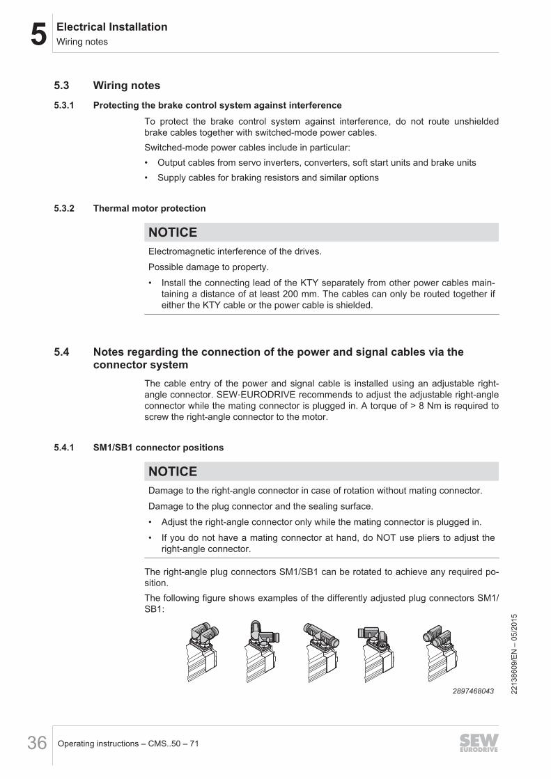
• If you do not have a mating connector at hand, do NOT use pliers to adjust theright-angle connector.
The right-angle plug connectors SM1/SB1 can be rotated to achieve any required po-sition.The following figure shows examples of the differently adjusted plug connectors SM1/SB1:
2897468043
2213
8609
/EN
– 0
5/20
15
5Electrical InstallationNotes regarding the connection of the power and signal cables via the connector system
Operating instructions – CMS..50 – 71 37
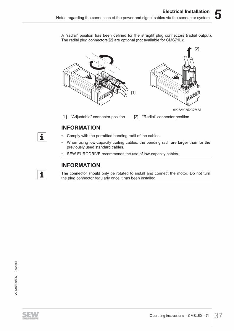
A "radial" position has been defined for the straight plug connectors (radial output).The radial plug connectors [2] are optional (not available for CMS71L):
[1]
[2]
9007202152204683
[1] "Adjustable" connector position [2] "Radial" connector position
INFORMATION• Comply with the permitted bending radii of the cables.
• When using low-capacity trailing cables, the bending radii are larger than for thepreviously used standard cables.
• SEW‑EURODRIVE recommends the use of low-capacity cables.
INFORMATIONThe connector should only be rotated to install and connect the motor. Do not turnthe plug connector regularly once it has been installed.
2213
8609
/EN
– 0
5/20
15
5 Electrical InstallationConnecting the motor and the encoder system via plug connector SM./ SB.
Operating instructions – CMS..50 – 7138
5.5 Connecting the motor and the encoder system via plug connector SM./ SB.The electric motors are supplied with the SM./SB. plug connector system.In the basic version, SEW‑EURODRIVE delivers electric motors with a connector onthe motor end and without mating connector. The encoder system is connected usinga separate 12-pin round plug connector (M23).The mating connectors can be ordered separately or together with the motor.
NOTICEPotential damage to the right-angle connector.
Possible damage to property.
• Do not align the right-angle connector frequently.
All servomotors are equipped with quick-lock right-angle or radial connectors (speed-tec ®). If you use connectors without quick lock, the O-ring serves as vibration protec-tor. The connector can only be screwed on until it reaches the O-ring. The connectoris always sealed at the bottom.If you are using self-assembled cables with quick lock, you have to remove the O-ring.
5.5.1 Plug connectors on cable side
Unit designation of the plug connectors
The following diagram shows a type designation:
S M 1 2
S S: Connector
M M: Motor, B: Brakemotor
1 1: Connector size 1 (1.5 – 4 mm2)
2 Cross section
1: 1.5 mm2, 2: 2.5 mm2, 4: 4 mm2
2213
8609
/EN
– 0
5/20
15
5Electrical InstallationConnecting the motor and the encoder system via plug connector SM./ SB.
Operating instructions – CMS..50 – 71 39
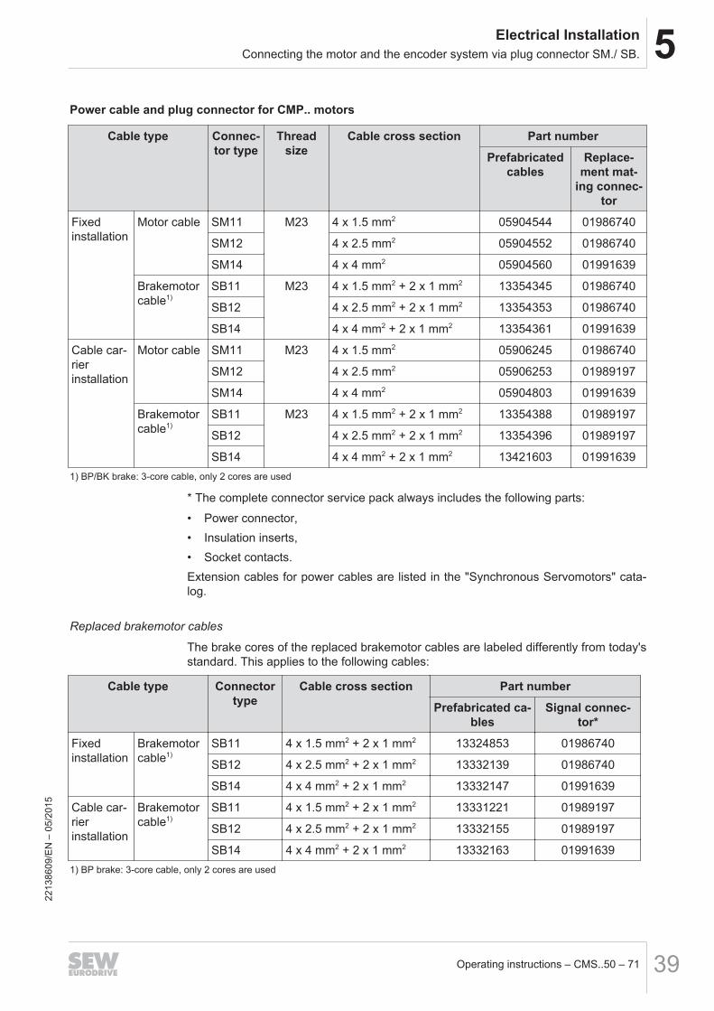
Power cable and plug connector for CMP.. motors
Cable type Connec-tor type
Threadsize
Cable cross section Part number
Prefabricatedcables
Replace-ment mat-
ing connec-tor
Fixed installation
Motor cable SM11 M23 4 x 1.5 mm2 05904544 01986740
SM12 4 x 2.5 mm2 05904552 01986740
SM14 4 x 4 mm2 05904560 01991639
Brakemotorcable1)
SB11 M23 4 x 1.5 mm2 + 2 x 1 mm2 13354345 01986740
SB12 4 x 2.5 mm2 + 2 x 1 mm2 13354353 01986740
SB14 4 x 4 mm2 + 2 x 1 mm2 13354361 01991639
Cable car-rier installation
Motor cable SM11 M23 4 x 1.5 mm2 05906245 01986740
SM12 4 x 2.5 mm2 05906253 01989197
SM14 4 x 4 mm2 05904803 01991639
Brakemotorcable1)
SB11 M23 4 x 1.5 mm2 + 2 x 1 mm2 13354388 01989197
SB12 4 x 2.5 mm2 + 2 x 1 mm2 13354396 01989197
SB14 4 x 4 mm2 + 2 x 1 mm2 13421603 019916391) BP/BK brake: 3-core cable, only 2 cores are used
* The complete connector service pack always includes the following parts:
• Power connector,• Insulation inserts,• Socket contacts.Extension cables for power cables are listed in the "Synchronous Servomotors" cata-log.
Replaced brakemotor cables
The brake cores of the replaced brakemotor cables are labeled differently from today'sstandard. This applies to the following cables:
Cable type Connectortype
Cable cross section Part number
Prefabricated ca-bles
Signal connec-tor*
Fixed installation
Brakemotorcable1)
SB11 4 x 1.5 mm2 + 2 x 1 mm2 13324853 01986740
SB12 4 x 2.5 mm2 + 2 x 1 mm2 13332139 01986740
SB14 4 x 4 mm2 + 2 x 1 mm2 13332147 01991639
Cable car-rier installation
Brakemotorcable1)
SB11 4 x 1.5 mm2 + 2 x 1 mm2 13331221 01989197
SB12 4 x 2.5 mm2 + 2 x 1 mm2 13332155 01989197
SB14 4 x 4 mm2 + 2 x 1 mm2 13332163 019916391) BP brake: 3-core cable, only 2 cores are used
2213
8609
/EN
– 0
5/20
15
5 Electrical InstallationConnecting the motor and the encoder system via plug connector SM./ SB.
Operating instructions – CMS..50 – 7140
Dependence of mating connector on cable diameter and crimping area
Mating connector typeSM1/SB1
Crimping area U, V, W,PE
mm2
Cable crimping diametermm
01986740 0.35 – 2.5 9 – 14
01989197 0.35 – 2.5 14 – 17
01991639 2.5 – 4 14 – 17
The connector service packs also contain the brake pins, so that no difference needsto be made between motor and brakemotor.
5.5.2 Encoder cables
Cable type Cable cross sec-tion
Frequency in-verter type
Part number
Prefabricatedcables
Signal connec-tor*
Fixed installation Resolver cable 5 x 2 x 0.25 mm2 MOVIDRIVE® 01994875 01986732
MOVIAXIS® 13327429
Cable carrier in-stallation
MOVIDRIVE® 01993194
MOVIAXIS® 13327437
Fixed installation HIPERFACE®
cable6 x 2 x 0.25 mm2 MOVIDRIVE® /
MOVIAXIS®13324535 01986732
Cable carrier in-stallation
MOVIDRIVE® /MOVIAXIS®
13324551
* The complete connector service pack always includes the following parts:
• Feedback connector,• Insulation inserts,• Socket contacts.Extension cables for power and feedback cables are listed in the "Synchronous Servo-motors" catalog.
5.5.3 Forced cooling fan cables
Cable type Cable cross sec-tion
Part number
Fixed installation Forced coolingfan cables
3 x 1 mm2 01986341
Cable carrier installation 3 x 1 mm2 0199560X
Extension cables for forced cooling fan cables are listed in the "Synchronous Servo-motors" catalog.
2213
8609
/EN
– 0
5/20
15
5Electrical InstallationConnecting the motor and the encoder system via plug connector SM./ SB.
Operating instructions – CMS..50 – 71 41
5.5.4 Prefabricated cablesPrefabricated cables are available from SEW‑EURODRIVE for connection with theSM./SB. plug connector system.For information on the prefabricated cables and part numbers, refer to the "Synchro-nous Servomotors" catalog.If you assemble cables yourself, observe the manual "Cable assembly".Note the following points if you want to assemble the cables yourself:
• The socket contacts for the motor connection are implemented as crimping con-tacts. Only use suitable tools for crimping.
• Strip the insulation off the connection leads. Apply heat shrink tubing to the con-nectors.
• Incorrectly installed socket contacts can be removed without removal tools.
5.5.5 Wiring diagrams – plug connectors for CMP. motors
Key
[A]
[C]
[B] [A]
[D]
[B]
8790995467
[A] View A[B] View B[C] Customer connector with socket contacts[D] Flange socket with pin contacts installed at the factory
SM1/SB1 power connector (M23)
Wiring diagram with/without BP/BK/BS brake
D
C
B
A
3
1
4
BK, BS=BU-
BP=YE
=RD+
BP=YE
BU
GNYE
RD
BKU1
V1
D
C
B
A
3
1
4
BK (1)
BK
GNYE
BK
BK
+/
U
V
W-/BK (3)
W1
[1] [A] [B]
[1]
BK, BS
14625714699
[1] BP/BK/BS-Brake (optional)
2213
8609
/EN
– 0
5/20
15
5 Electrical InstallationConnecting the motor and the encoder system via plug connector SM./ SB.
Operating instructions – CMS..50 – 7142
Wiring diagram for RH1M resolver signal plug connectors
Wiring diagram
1 98
2
10 12
7
3
4 5
6
11
GY
RD
BU
BNVT
GN
YE
PK
WHBK
198
2
1012
7
3
45
6
11
BKWH
BU (BK)
RD
RD (BK)
BU
YE
RDWH
BK
R1 (Reference +)
R2 (Reference -)
KTY- (TF) [2]
S1 (Cosine +)
S3 (Cosine -)
S4 (Sine -)
S2 (Sine +)
KTY+ (TF)
[2] [B][1][A]
8790991627
[1] Shield connected to the metal housing of the connector. Colors according toSEW-EURODRIVE cables
[2] KTY+ (RD), KTY-(BU), optional TF (BK)
Pin assignment of plug connector lower part
Pin Color code Connection
1 RD/WH R1 (reference +)
2 BK/WH R2 (reference -)
3 RD S1 (cosine +)
4 BK S3 (cosine –)
5 YE S2 (sine +)
6 BU S4 (sine –)
7 – –
8 – –
9 RD KTY +
10 BU KTY –
11 – –
12 – –
2213
8609
/EN
– 0
5/20
15

5Electrical InstallationConnecting the motor and the encoder system via plug connector SM./ SB.
Operating instructions – CMS..50 – 71 43
Connection of signal plug connector encoder AK0H, EK0H, AK1H, EK1H, AS1H, ES1H
Wiring diagram
1 9
82
10 12
7
3
4 5
6
11 GNRD
BU
BN
RDBU; GY
YE
VT
WH
GYPK; PK
BK
BU
19
82
1012
7
3
45
611
RDGN
YE
BK
VT
GY
PK
BU (BK)
RD (BK)[A]
[1] [2][B]
[2]KTY- (TF)
S1 (Cosine +)
S3 (Cosine -)
GND
S2 (Sine +)
S4 (Sine -)
Us
D -
D +
KTY+ (TF)
8790993547
[1] Shield connected to the metal housing of the connector. Colors according toSEW‑EURODRIVE cables
[2] KTY+ (RD), KTY-(BU), optional TF (BK)
Pin assignment of plug connector lower part
Pin Color code Connection
1 – –
2 – –
3 RD S1 (cosine +)
4 BU S3 (cosine –)
5 YE S2 (sine +)
6 GN S4 (sine –)
7 VT D –
8 BK D +
9 RD KTY +
10 BU KTY –
11 PK Voltage reference (GND)
12 GY Supply voltage Vs
2213
8609
/EN
– 0
5/20
15
5 Electrical InstallationConnecting the motor and the encoder system via plug connector SM./ SB.
Operating instructions – CMS..50 – 7144
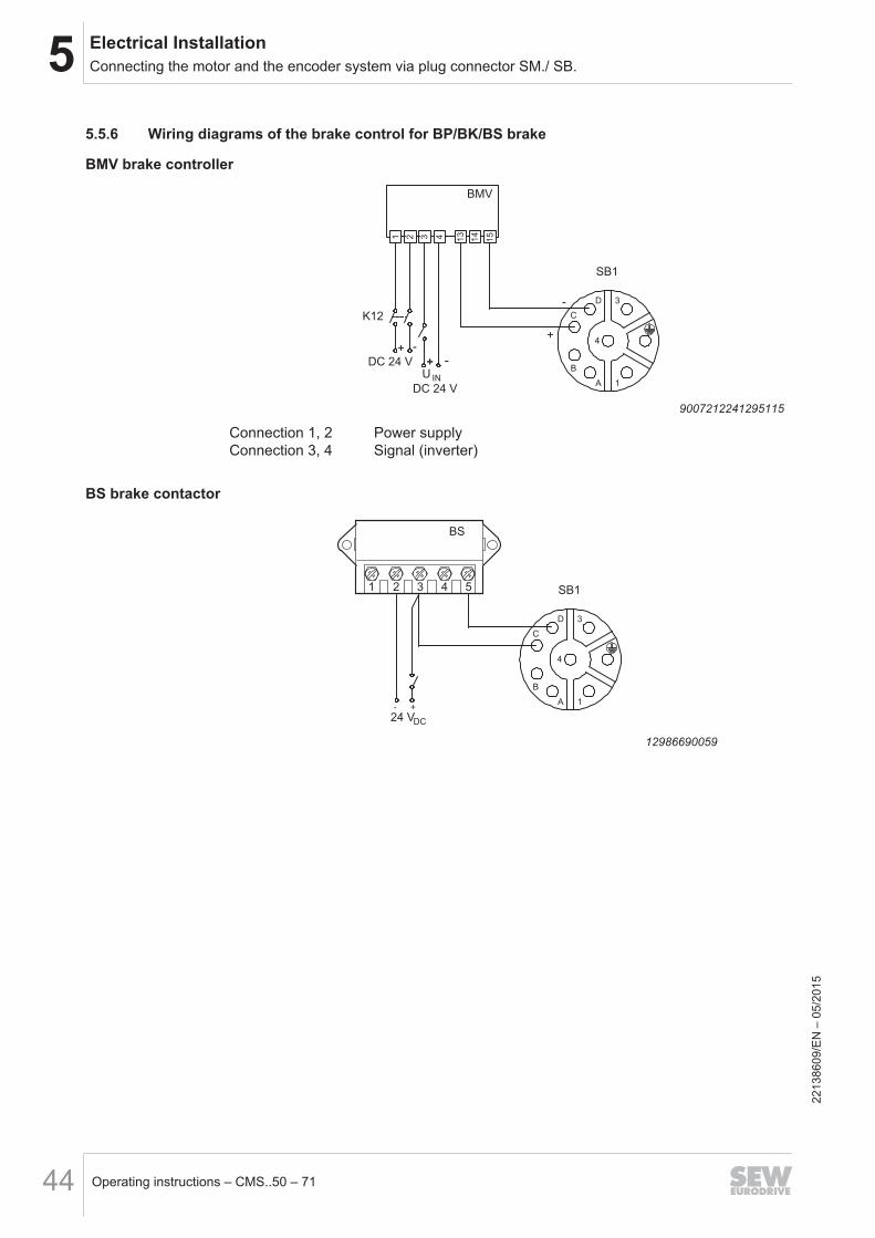
5.5.6 Wiring diagrams of the brake control for BP/BK/BS brake
BMV brake controller
D
C
B
A
3
1
4
BMV
1 2 3 4 13
14
15
SB1
K12
+ -
U
DC 24 V
IN
DC 24 V
+ -
+ -
-
+
9007212241295115
Connection 1, 2 Power supplyConnection 3, 4 Signal (inverter)
BS brake contactor
D
C
B
A
3
1
4
BS
SB1
24 VDC
- +
1 2 3 4 5
12986690059
2213
8609
/EN
– 0
5/20
15
5Electrical InstallationConnecting the motor and the encoder system via plug connector SM./ SB.
Operating instructions – CMS..50 – 71 45
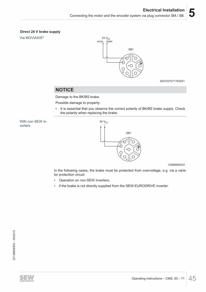
Direct 24 V brake supply
D
C
B
A
3
1
4
SB1
24 VDC
BGND DBØØ
9007207071783051
NOTICEDamage to the BK/BS brake.
Possible damage to property.
• It is essential that you observe the correct polarity of BK/BS brake supply. Checkthe polarity when replacing the brake.
D
C
B
A
3
1
4
SB1
24 VDC
- +
12986696203
In the following cases, the brake must be protected from overvoltage, e.g. via a varis-tor protection circuit:• Operation on non-SEW inverters,• if the brake is not directly supplied from the SEW‑EURODRIVE inverter.
Via MOVIAXIS®
With non‑SEW in-verters
2213
8609
/EN
– 0
5/20
15
5 Electrical InstallationConnecting the motor and the encoder system via KK/KKS terminal box to CMSMB50/63/71
Operating instructions – CMS..50 – 7146
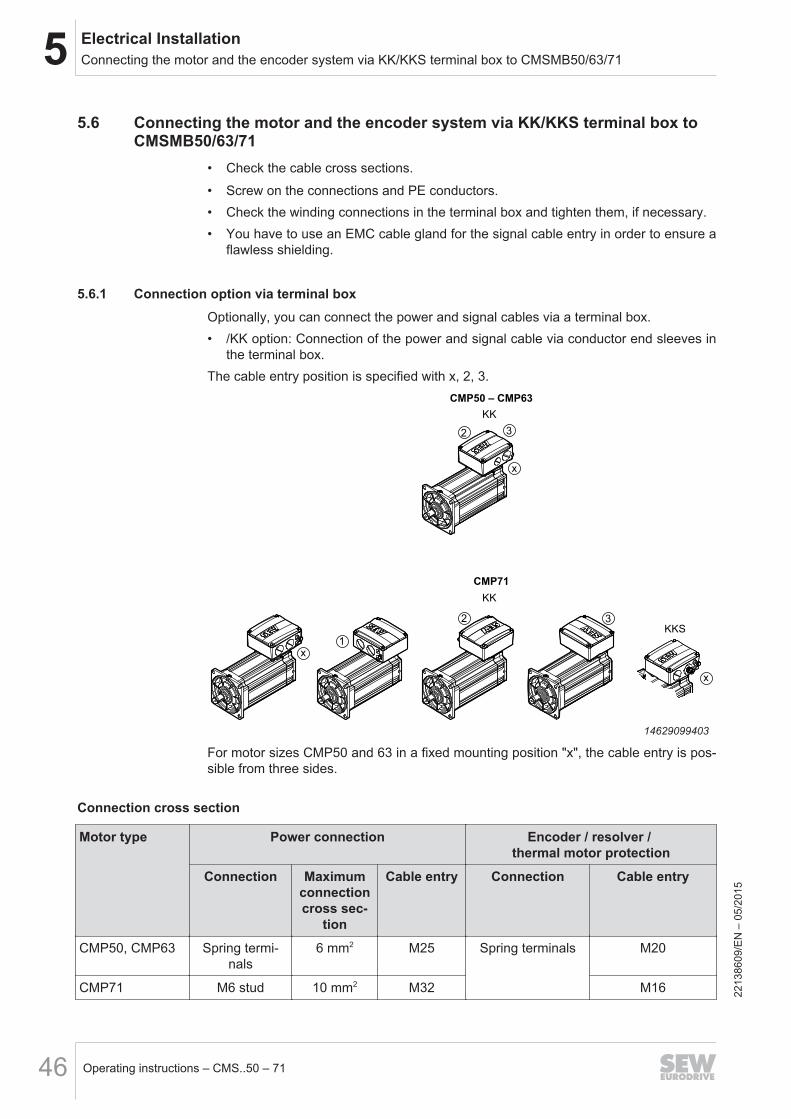
5.6 Connecting the motor and the encoder system via KK/KKS terminal box toCMSMB50/63/71
• Check the cable cross sections.
• Screw on the connections and PE conductors.• Check the winding connections in the terminal box and tighten them, if necessary.• You have to use an EMC cable gland for the signal cable entry in order to ensure a
flawless shielding.
5.6.1 Connection option via terminal boxOptionally, you can connect the power and signal cables via a terminal box.• /KK option: Connection of the power and signal cable via conductor end sleeves in
the terminal box.The cable entry position is specified with x, 2, 3.
2 3
x
KK
CMP50 – CMP63
1
2 3
x
x
KKS
KK
CMP71
14629099403
For motor sizes CMP50 and 63 in a fixed mounting position "x", the cable entry is pos-sible from three sides.
Connection cross section
Motor type Power connection Encoder / resolver / thermal motor protection
Connection Maximumconnectioncross sec-
tion
Cable entry Connection Cable entry
CMP50, CMP63 Spring termi-nals
6 mm2 M25 Spring terminals M20
CMP71 M6 stud 10 mm2 M32 M16
2213
8609
/EN
– 0
5/20
15
5Electrical InstallationConnecting the motor and the encoder system via KK/KKS terminal box to CMSMB50/63/71
Operating instructions – CMS..50 – 71 47
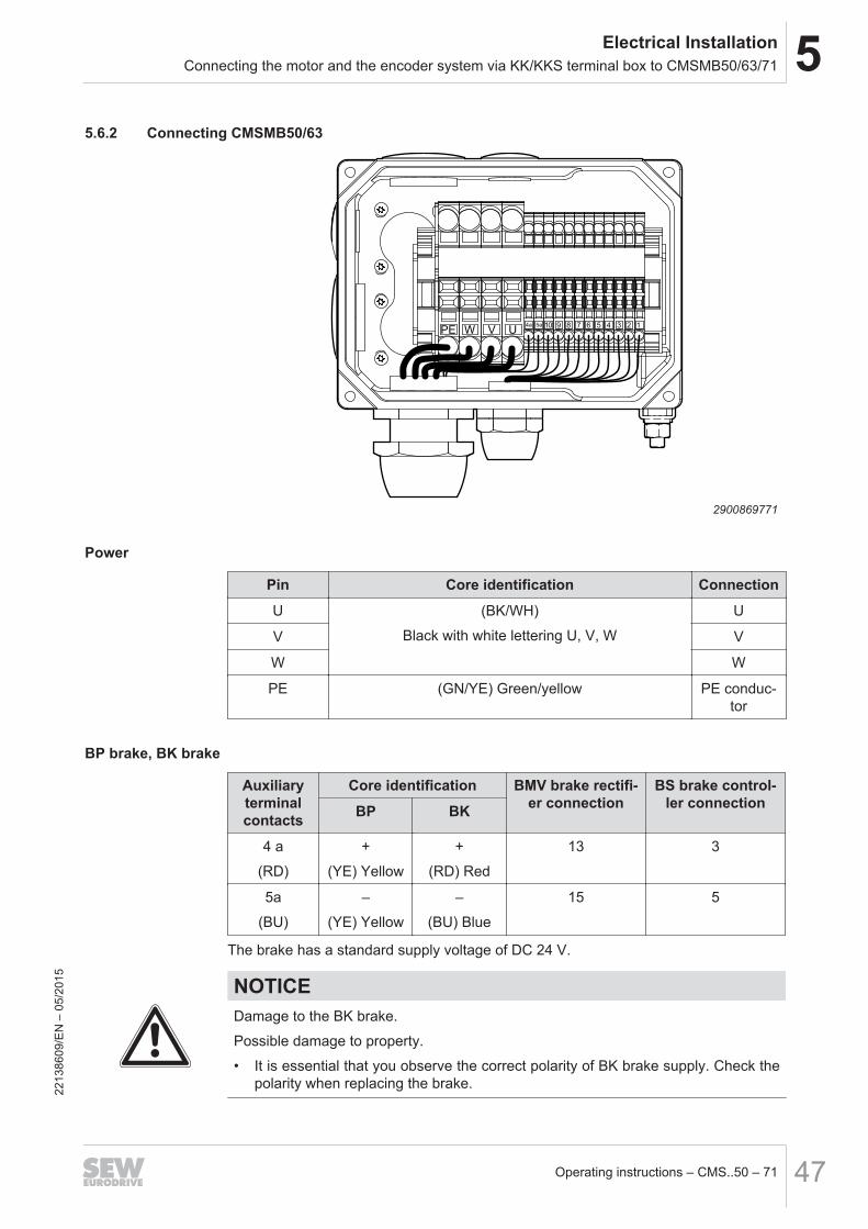
5.6.2 Connecting CMSMB50/63
123456789105a4a
UVWPE
2900869771
Power
Pin Core identification Connection
U (BK/WH)
Black with white lettering U, V, W
U
V V
W W
PE (GN/YE) Green/yellow PE conduc-tor
BP brake, BK brake
Auxiliaryterminalcontacts
Core identification BMV brake rectifi-er connection
BS brake control-ler connectionBP BK
4 a
(RD)
+
(YE) Yellow
+
(RD) Red
13 3
5a
(BU)
–
(YE) Yellow
–
(BU) Blue
15 5
The brake has a standard supply voltage of DC 24 V.
NOTICEDamage to the BK brake.
Possible damage to property.
• It is essential that you observe the correct polarity of BK brake supply. Check thepolarity when replacing the brake.
2213
8609
/EN
– 0
5/20
15
5 Electrical InstallationConnecting the motor and the encoder system via KK/KKS terminal box to CMSMB50/63/71
Operating instructions – CMS..50 – 7148
Signal
Resolver Encoder
1 ref + Reference 1 cos + Cosine
2 ref - 2 ref cos Reference
3 cos + Cosine 3 sin + Sine
4 cos - 4 ref sin Reference
5 sin + Sine 5 D - DATA
6 sin - 6 D + DATA
7 - – 7 GND Ground
8 - – 8 Us Supply voltage
9 KTY + / (TF) Motor protection 9 KTY + / (TF) Motor protection
10 KTY - / (TF) 10 KTY - / (TF)
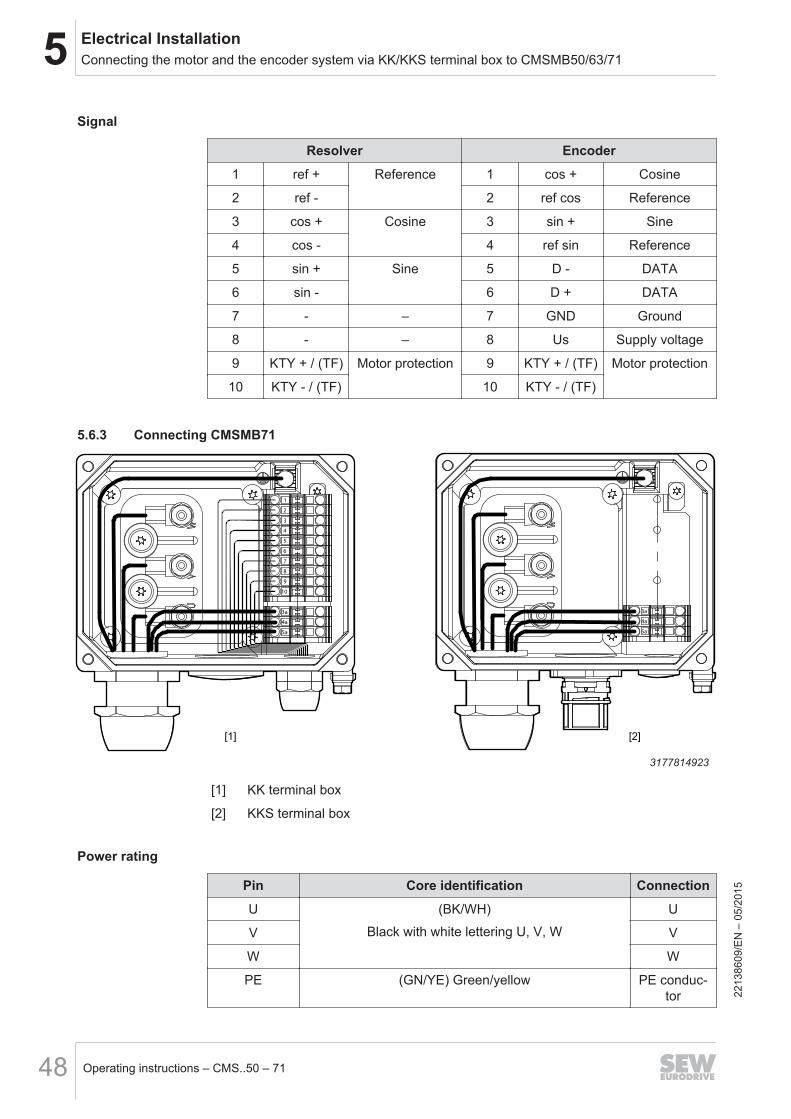
5.6.3 Connecting CMSMB71
1
2
3
4
5
6
7
8
9
10
3a
4a
5a
3a
4a
5a
[1] [2]
3177814923
[1] KK terminal box
[2] KKS terminal box
Power rating
Pin Core identification Connection
U (BK/WH)
Black with white lettering U, V, W
U
V V
W W
PE (GN/YE) Green/yellow PE conduc-tor
2213
8609
/EN
– 0
5/20
15
5Electrical InstallationConnecting the motor and the encoder system via KK/KKS terminal box to CMSMB50/63/71
Operating instructions – CMS..50 – 71 49
BP brake
Auxiliary ter-minal con-
tacts
Core identification BMV brake rectifi-er connection
BS brake controllerconnection
4 a (BK/WH)
Black with white lettering 1, 2, 3
13 3
5a 15 5
The brake has a standard supply voltage of DC 24 V.
Signal
Resolver Encoder
1 ref + Reference 1 cos + Cosine
2 ref – 2 ref cos Reference
3 cos + Cosine 3 sin + Sine
4 cos – 4 ref sin Reference
5 sin + Sine 5 D – DATA
6 sin – 6 D + DATA
7 – – 7 GND Ground
8 – – 8 Us Supply voltage
9 KTY + / (TF) Motor protection 9 KTY + / (TF) Motor protection
10 KTY – / (TF) 10 KTY – / (TF)
2213
8609
/EN
– 0
5/20
15
5 Electrical InstallationConnecting the motor and the encoder system via KK/KKS terminal box to CMSMB50/63/71
Operating instructions – CMS..50 – 7150
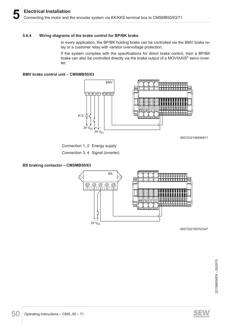
5.6.4 Wiring diagrams of the brake control for BP/BK brakeIn every application, the BP/BK holding brake can be controlled via the BMV brake re-lay or a customer relay with varistor overvoltage protection.If the system complies with the specifications for direct brake control, then a BP/BKbrake can also be controlled directly via the brake output of a MOVIAXIS® servo inver-ter.
BMV brake control unit – CMSMB50/63
BMV
1 2 3 4 13
14
15
K12
+ -
24 VDC
24 VDC
123456789105a4a
UVWPE
9007202156696971
Connection 1, 2 Energy supply
Connection 3, 4 Signal (inverter)
BS braking contactor – CMSMB50/63
123456789105a4a
UVWPE
24 VDC
- +
BS
1 2 3 4 5
9007202156702347
2213
8609
/EN
– 0
5/20
15
5Electrical InstallationOptions
Operating instructions – CMS..50 – 71 51
5.7 Options5.7.1 BP/BK/BS brake
The mechanical BP brake is a holding brake implemented as a spring-loaded brake.The BK and BS brakes are permanent magnet holding brakes, they are released elec-trically and are applied by the magnetic force of the permanent magnets. They differfrom the BP brakes by the fixed coil polarity.
For further information, refer to chapter Technical Data (→ 2 51).
5.7.2 Thermal motor protection
NOTICEDue to the low thermal time constants of the winding, thermal motor protection forCMS50 – CMP.71S motors is only possible when, in addition to a temperature sen-sor, a current monitoring device (I2t, rms current monitoring) or a motor model forthermal protection, as installed in SEW servo systems, is activated.
Complete motor protection at full motor/electric cylinder capacity utilization is onlyensured if the signals are evaluated by SEW‑EURODRIVE inverters.
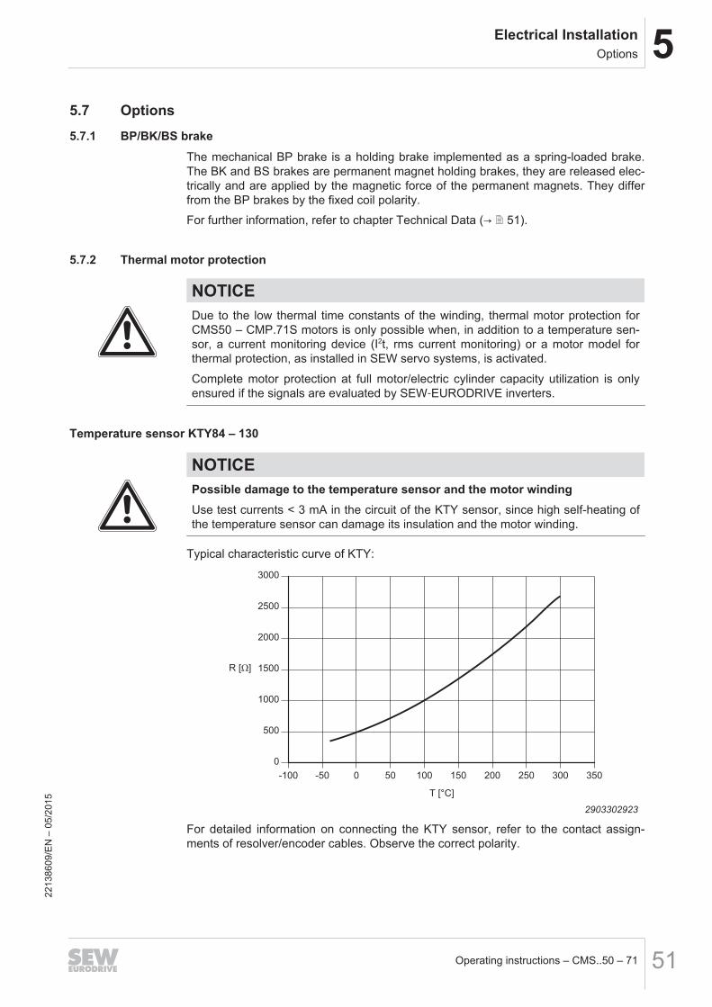
Temperature sensor KTY84 – 130
NOTICEPossible damage to the temperature sensor and the motor windingUse test currents < 3 mA in the circuit of the KTY sensor, since high self-heating ofthe temperature sensor can damage its insulation and the motor winding.
Typical characteristic curve of KTY:
0
500
1000
1500
2000
2500
3000
-100 -50 0 50 100 150 200 250 300 350
T [°C]
R [Ω]
2903302923
For detailed information on connecting the KTY sensor, refer to the contact assign-ments of resolver/encoder cables. Observe the correct polarity.
2213
8609
/EN
– 0
5/20
15

5 Electrical InstallationOptions
Operating instructions – CMS..50 – 7152
TF temperature sensor
NOTICEToo high input voltage at the temperature sensor input can damage the motor wind-ing and the insulation of the sensor as well as the semiconductor.
Possible damage to property.
• Make sure that the TF evaluation unit is connected correctly.
• Do not connect a voltage > 10 V.
The PTC thermistors comply with DIN 44082.Resistance measurement (measuring instrument with V ≤ 2.5 V or I < 1 mA)• Standard measured values: 20 ... 500 Ω, hot resistance > 4000 Ω
5.7.3 VR forced cooling fanFor the electric cylinder sizes CMS50, CMSB50/63/71, CMSMB50/63/71, the synchro-nous servomotors can be equipped with a VR forced cooling fan as an option.
Electrical connection
CAUTIONStarting up the fan before it is installed.
Risk of injury due to rotating parts.
• The fan may only be started up once it is installed.
The VR forced cooling fan is only available for DC 24 V voltage.
• DC 24 V ± 20%
• Plug connector connection• Maximum connection cross section 2 x 1 mm2
• Pg7 cable gland with 7 mm inside diameter
1
2-
+DC 24 V
2903419147
Connector contact Connection
1 24 V +
2 0 V
2213
8609
/EN
– 0
5/20
15
6StartupImportant notes on startup
Operating instructions – CMS..50 – 71 53
6 Startup6.1 Important notes on startup
WARNINGRisk of injury due to electric shock.
Severe or fatal injuries.
• It is essential to comply with the safety notes in chapter 2 during installation!
• Use switch contacts in utilization category AC-3 according to EN 60947-4-1 forswitching the motor and the brake.
• When motors are powered by inverters, you must adhere to the wiring instruc-tions issued by the inverter manufacturer.
• Observe the operating instructions of the frequency inverter.
WARNINGWith lifting applications, make sure that the holding torque M4, 100 °C of the brake isbigger than the corresponding load torque of the application.
Severe or fatal injuries.
• Observe the project planning guidelines.
• The spindles that are used are not self-locking.
• See chapter "Possible maximum holding forces" (→ 2 104).
WARNINGThe electric cylinders may not execute any safety functions without master safetysystems.
Severe or fatal injuries.
• Use master safety systems to ensure that equipment and personnel are protec-ted.
WARNINGRisk of crushing due to incorrect use, installation or operation leading to verticalmovement of the spindle.
Severe or fatal injuries.
• Take measures to prevent inadvertent contact.
CAUTIONThe electric cylinder can get very hot during operation.
Risk of burns.
• Never touch the electric cylinder during operation or in the cool down phase onceit has been switched off.
2213
8609
/EN
– 0
5/20
15
6 StartupBefore startup
Operating instructions – CMS..50 – 7154
NOTICEThe rated speed (nN) of the motor can be higher than the mechanically permittedspeed (npk).
Possible damage to property.
• Limit the maximum speed at the servo inverter. For information on the procedure,refer to the documentation of the servo inverter.
NOTICEWith electric cylinders, the maximum limit torque (Mpk) and the maximum current(Imax) may not be exceeded, not even for acceleration.
Possible damage to property.
• Limit the maximum current/the maximum torque on the servo inverter.
6.2 Before startup• The motors may only be operated in combination with frequency inverters.
• Before startup, frequency inverters must be configured using the MotionStudio soft-ware.
• A suitable frequency inverter is chosen during project planning. For further informa-tion on project planning, refer to the "Synchronous Servomotors" catalog.
• The drive must be undamaged and not blocked.
• All connections have to be made correctly.
• All protective covers have to be fitted correctly.
• All motor protection devices must be active.
• There must not be any other sources of danger.• The motor surface must not be covered by heat-sensitive or insulating materials.• When motors with BK brake are stored for more than 6 months, the function of the
BK brake must be checked. We recommend a running-in routine (3 minutes run-ning at 300 1/min, brake application 1-2 times per second).
2213
8609
/EN
– 0
5/20
15
7Inspection/maintenanceGeneral maintenance work
Operating instructions – CMS..50 – 71 55
7 Inspection/maintenance
WARNINGRisk of crushing if the drive starts up unintentionally.
Severe or fatal injuries.
• De-energize the electric cylinder before you start working on the unit.
• Safeguard the electric cylinder against unintentional restart.
CAUTIONThe electric cylinder can get very hot during operation.
Risk of burns.
• Never touch the electric cylinder during operation or in the cool down phase onceit has been switched off.
NOTICEImproper inspection/maintenance may result in damages to the electric cylinder.
Possible damage to property.
• Note the following information.
• Strictly observe the safety notes in the individual chapters.
• Components may be subject to mechanical loads. Before removing the electric cyl-inder, ensure that the structure provided by the customer is supported and se-cured.
• Before starting work, isolate the electric cylinder and brake from the power supply.Safeguard the electric cylinder against unintentional restart.
• Use only genuine spare parts in accordance with the valid spare parts list.
7.1 General maintenance workThe electric cylinder is maintenance-free except for the threaded spindles. Replacedefective parts if possible.Depending on the ambient conditions, remove any traces of dirt, chips, dust, etc. fromthe bellows (only CMS71L) with a soft cloth.Mobile cables are subject to wear and must be checked for visible changes in regularintervals.With CMSMB./AP with toothed belt, you have to replace the toothed belt in regular in-tervals.
2213
8609
/EN
– 0
5/20
15
7 Inspection/maintenanceLubrication of the threaded spindle CMS50/CMS71
Operating instructions – CMS..50 – 7156
7.2 Lubrication of the threaded spindle CMS50/CMS71There may be a loss of lubricant between the nut and spindle in threaded spindles.Lubricants also decrease in quality and effectiveness with age and wear. This meanslubrication is required at regular intervals.The lubrication for threaded spindles is to be specified accurately in terms of type,quantity and relubrication intervals. These depend on:
• Load
• Speed
• Cyclic duration factor
• Type of threaded spindle (recirculating ball screw or planetary screw drive)• Ambient temperature• Degree of pollution caused by dust, humidity, etc.
INFORMATIONThe following information is intended as recommendations only. It is not intended toreplace individual project planning for every application.
Permanent relubrication (for example via connection to lubrication system) is basicallythe preferred solution over lubrication at certain intervals.Relubrication at intervals is not recommended for planetary screw drives, which canrequire about 2-5 times more lubricant than recirculating ball screws.
7.2.1 General information
INFORMATIONThe amount of lubricant filled into the electric cylinder accumulates inside the drive.Used lubricant must be removed from the inside of the motor after five years at thelatest.Service work must be performed by SEW‑EURODRIVE service only. During servicework, the spindle must be removed from the unit and the old lubricant removed fromthe spindle's surface.
2213
8609
/EN
– 0
5/20
15
7Inspection/maintenanceLubrication of the threaded spindle CMS50/CMS71
Operating instructions – CMS..50 – 71 57
7.2.2 Size CMS50A taper greasing nipple DIN 71412 [1] for manual relubrication with a grease gun isinstalled as standard on the spindle nut in the inside of the motor. The grease nipple isaccessible via screw plugs [1]. In order to reach it, slowly move the drive until thegrease nipple is visible.
[1]
4139224971
7.2.3 Size CMS71A taper greasing nipple DIN 71412 [1] for manual relubrication with a grease gun isinstalled as standard on the motor.
[1]
4139223051
2213
8609
/EN
– 0
5/20
15
7 Inspection/maintenanceLubricant for recirculating ball screws and planetary roller screw drives for CMS50 and CMS71
Operating instructions – CMS..50 – 7158
7.3 Lubricant for recirculating ball screws and planetary roller screw drives forCMS50 and CMS71
CMS.. electric cylinders are filled with the lubricant Fuchs RENOLIT CX-TOM15 asstandard.Instead, you can order the CMS50/71 motor with food-grade lubricant OBEEN FS 2from Castrol.
INFORMATIONOnly the following lubricants may be used for relubricating the electric cylinders:
• Standard: Fuchs RENOLIT CX-TOM15
• Food grade: Castrol OBEEN FS 2
The lubricant Fuchs Renolit CX-TOM15 is available as 400 g cartridge (DIN 1284)from SEW‑EURODRIVE under part no. 03207196.
4139347851
The cartridge is suitable for grease guns in line with DIN 1283 with connection piecefor DIN 71412 taper greasing nipples.
4139349771
2213
8609
/EN
– 0
5/20
15
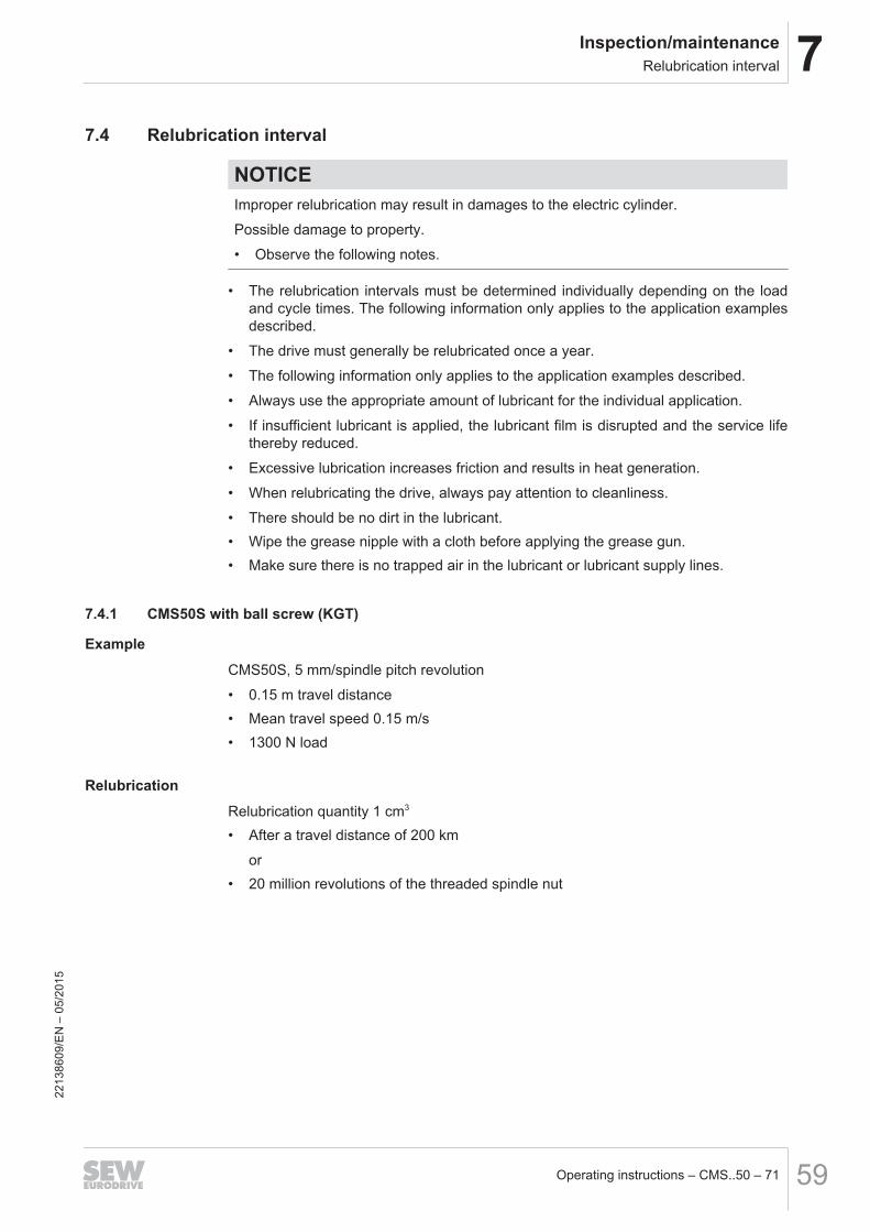
7Inspection/maintenanceRelubrication interval
Operating instructions – CMS..50 – 71 59
7.4 Relubrication interval
NOTICEImproper relubrication may result in damages to the electric cylinder.
Possible damage to property.
• Observe the following notes.
• The relubrication intervals must be determined individually depending on the loadand cycle times. The following information only applies to the application examplesdescribed.
• The drive must generally be relubricated once a year.
• The following information only applies to the application examples described.
• Always use the appropriate amount of lubricant for the individual application.
• If insufficient lubricant is applied, the lubricant film is disrupted and the service lifethereby reduced.
• Excessive lubrication increases friction and results in heat generation.
• When relubricating the drive, always pay attention to cleanliness.
• There should be no dirt in the lubricant.• Wipe the grease nipple with a cloth before applying the grease gun.• Make sure there is no trapped air in the lubricant or lubricant supply lines.
7.4.1 CMS50S with ball screw (KGT)
Example
CMS50S, 5 mm/spindle pitch revolution
• 0.15 m travel distance• Mean travel speed 0.15 m/s• 1300 N load
Relubrication
Relubrication quantity 1 cm3
• After a travel distance of 200 km
or• 20 million revolutions of the threaded spindle nut
2213
8609
/EN
– 0
5/20
15
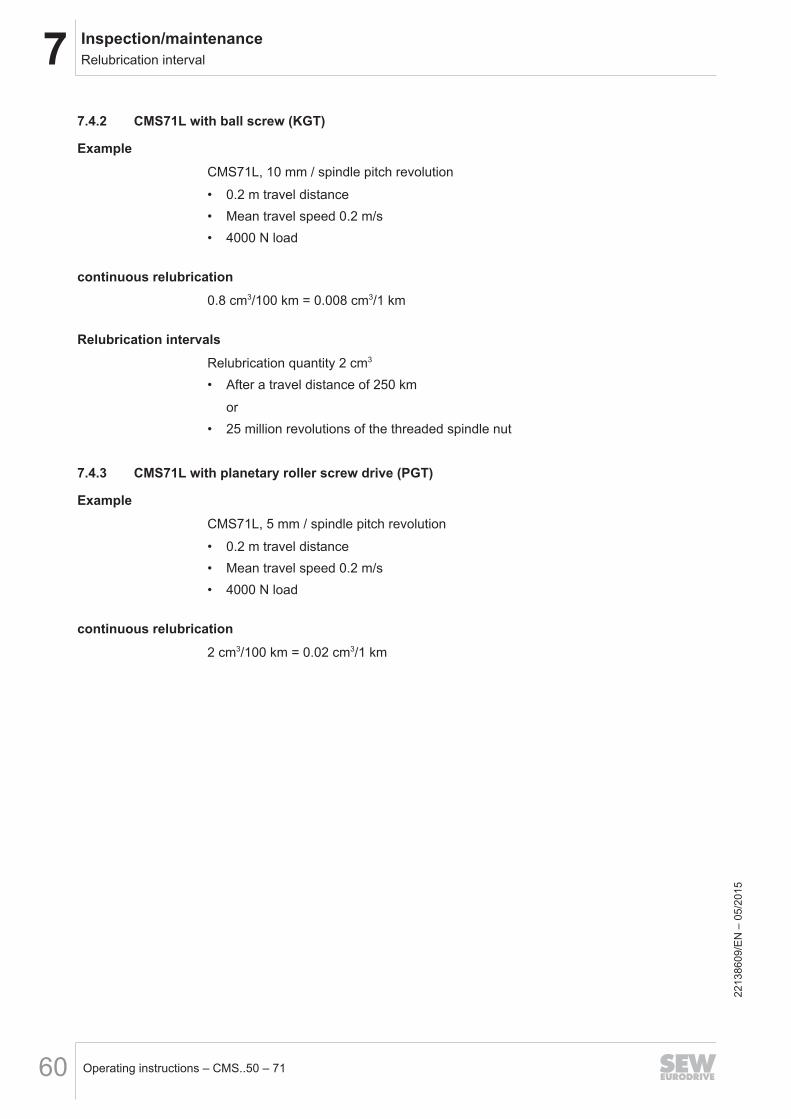
7 Inspection/maintenanceRelubrication interval
Operating instructions – CMS..50 – 7160
7.4.2 CMS71L with ball screw (KGT)
Example
CMS71L, 10 mm / spindle pitch revolution
• 0.2 m travel distance• Mean travel speed 0.2 m/s• 4000 N load
continuous relubrication
0.8 cm3/100 km = 0.008 cm3/1 km
Relubrication intervals
Relubrication quantity 2 cm3
• After a travel distance of 250 km
or• 25 million revolutions of the threaded spindle nut
7.4.3 CMS71L with planetary roller screw drive (PGT)
Example
CMS71L, 5 mm / spindle pitch revolution
• 0.2 m travel distance• Mean travel speed 0.2 m/s• 4000 N load
continuous relubrication
2 cm3/100 km = 0.02 cm3/1 km
2213
8609
/EN
– 0
5/20
15
7Inspection/maintenanceLubricator – only for CMS71
Operating instructions – CMS..50 – 71 61
7.5 Lubricator – only for CMS71On request, the electric cylinders of size CMS71L can be equipped with a lubricator.The threaded spindle nut is relubricated continuously with this option.The lubricator comprises a drive unit with an electric motor, which is supplied withpower either with a set of batteries (Vario lubrication system) or with 24 V and functionmonitoring (Control time/impulse lubrication system). This motor drains the lubricantcontainer via a piston rod. The Control lubrication system is connected to a customercontrol device via a cable (length 5 m, included in the delivery).The threaded elbow joints are mounted, filled with lubricant and vented by default.The time between lubrications is set to one year at the production plant and is suffi-cient for normal applications.For cases with high annual operating time, e.g. 24 operating hours per day or an op-erational performance of > 2 km/day, contact SEW‑EURODRIVE.For installation and settings of the lubricator, refer to the document "Installation In-structions – CMS.. Electric Cylinder – Star Vario / Star Control" on the websitewww.sew-eurodrive.de.
2213
8609
/EN
– 0
5/20
15

7 Inspection/maintenanceSealing air
Operating instructions – CMS..50 – 7162
7.6 Sealing airAt the factory, the drive is equipped with a sealing air connection [1] thread G1/8 asstandard. This is why the electric cylinder can be used in dusty environments in partic-ular.In this case, the space within the bellows [2] can be placed under slight positive pres-sure (max. 0.5 bar). The positive pressure prevents dust, etc., from entering the motor.
[1] [2]
4139100171
[1] Sealing air connection[2] Bellows
The compressed air volume flow (VSealingair) that is required depends on the travelspeed (v) of the threaded spindle.
Vsealing air≥ 300 vVolume flow VSealingair in liter/min
Travel speed v in m/s
This ensures that sufficient compressed air flows in during extension and that no neg-ative pressure develops in the space [2].The compressed air must be dry and free of oil, according to DIN-ISO 8573‑1 class 3(common in pressurized air systems).
2213
8609
/EN
– 0
5/20
15
7Inspection/maintenanceFilter ventilation CMS71
Operating instructions – CMS..50 – 71 63
7.7 Filter ventilation CMS71If the electric cylinder CMS71 is used in dusty environments, you must make sure thatno dust is sucked in through the venting [4] of the bellows in the joint during the liftingmotion.There are two possibilities to do so:• Sealing air• Filter ventilation (no compressed air required)
INFORMATIONThe filter ventilation is not included in the SEW‑EURODRIVE delivery.
For this purpose, a suitable filter [2] is installed at the sealing air connection [1] withG1/8 thread. If there is not enough space, the filter can be connected to the electriccylinder via a hose [3]. Max. hose length 1 m, inner diameter > 9 mm.SEW recommends a type L1.0807-11 filter from Argo-Hythos http://www.argo-hy-tos.com. This is an inexpensive filter that is used for venting hydraulic vessels on con-struction machinesThis filter safely keeps back dust particles < 3 µm under very low pressure. Other fil-ters, such as pneumatic mufflers, sintered metal filters, etc., may not be used.In addition to this, the default venting via the joint must be sealed. The sealed joint canbe ordered under "Option without bellows venting" or retrofitted using 2 x sealing ele-ment [4], SEW part no. 13342093. Older versions are sealed with rubber.
[2]
[1]
[3]
[4][5]
9007204624887691
[1] Sealing air connection [4] Sealing element[2] Filter [5] Joint[3] Hose
7.8 Liquid coolingLiquid cooling can significantly increase the thermal capacity of the drive. The data forliquid cooling in the power diagrams for the thermal limit torque are based on the fol-lowing parameters:
• Temperature of cooling liquid inlet 25 °C
2213
8609
/EN
– 0
5/20
15
7 Inspection/maintenanceLiquid cooling
Operating instructions – CMS..50 – 7164
• Temperature increase at cooling liquid outlet about 5 °C• Flow rate: 2 l/min for CMSB50, CMSMB50• Flow rate: 4 l/min for CMSB63/70, CMSMB63/70Higher flow rates increase the cooling effect only slightly.Cooling liquid requirements:
• Max. operating pressure 2 bar
• demineralized and desalinated• No foreign objects and sediments• Frost protection, if necessaryThe components through which the cooling liquid flows are corrosion-protected. Thecooling liquid must not contain any chemically aggressive additives; contactSEW‑EURODRIVE if necessary.
7.8.1 Liquid cooling at CMSB50, CMSMB50 (in preparation)The CMSB50, CMSMB50 can optionally be equipped with a connection option for liq-uid cooling.Inlet and outlet connection for cooling liquid can be exchanged.(similar to CMSMB50/ACH, ACA)In this case, a cooling option is provided between motor and linear unit in the couplinghousing.
[1]
14667867659
[1] Cooling liquid connection 2x G1/8 deep (flange seal and screw fitting supplied bythe customer)
CMSB50
2213
8609
/EN
– 0
5/20
15
7Inspection/maintenanceLiquid cooling
Operating instructions – CMS..50 – 71 65
At this design, the liquid cooling is integrated in the servomotor flange.[1]
14668292747
[1] Cooling liquid connection 2x G1/8; 8 mm deep (flange seal and screw fitting sup-plied by the customer)
7.8.2 Liquid cooling at CMSB63/71, CMSMB63/71The CMSB63/71, CMSMB63/71 is equipped with a liquid cooling connection option asstandard.Inlet and outlet connection for cooling liquid can be exchanged.
[1]
9007204622448523
[1] Cooling liquid connection 2x G1/8 (flange seal and screw fitting supplied by thecustomer)
CMSMB50/AP
2213
8609
/EN
– 0
5/20
15
7 Inspection/maintenanceOil bath lubrication of CMSB50/63/71, CMSMB50/63/71
Operating instructions – CMS..50 – 7166
7.9 Oil bath lubrication of CMSB50/63/71, CMSMB50/63/71The CMSB50/63/71, CMSMB50/63/71 electric cylinders are equipped with an oil bathlubrication with little maintenance requirements. The only required maintenance meas-ure is a regular visual check for leaks. The oil need not be changed in usual applica-tions.An oil change might make sense for applications with the following higher require-ments:
• Travel cycles with a cyclic duration factor > 60% and an operational performance of> 1 km/hour.
• Working strokes < 10 mm with stroke frequencies > 5 Hz• Expected service life > 10 000 hours of nominal operationPlease contact SEW‑EURODRIVE in such cases.The CMSB50/63/71, CMSMB50/63/71 electric cylinders are filled with the lubricantMobil SHC630 as standard. This lubricant is used for recirculating ball screws andplanetary roller screws.As an alternative, you can order CMSB50/63/71, CMSMB50/63/71 with food-gradeCastrol OPTIMOL OPTILEB GT from SEW‑EURODRIVE.
7.10 Size CMSB50/63/71 and CMSMB50/63/71 with oil bath lubrication
INFORMATIONThe oil screw plug of the electric cylinder must not be opened.
The sealing system and the components have been developed and tested to comple-ment each other. Observe the following notes in order not to reduce the service life:
• Do not paint the piston rod
• Do not expose the piston rod to potential damage resulting from hard components
• Protect the piston rod from clinging foreign substances (e.g. cleaning agent, sweat)• Make sure that the joints are free to move• Visually check for any leakages regularly, at least every other week
7.10.1 Replacement interval of wearing partsThe drive reaches the end of its service life after 10 000 hours of nominal operation. Ageneral overhaul and refit of the drive is not recommended.
Electric cylinders Replacement intervals of the components
CMSB50/63/71,CMSMB50/63/71
Threaded spindle Not necessary
A- and B-side bearing Not necessary
Gasket Not necessary
CMSMB50/63/71/AP Toothed belt 7.5 million doublestrokes
2213
8609
/EN
– 0
5/20
15
7Inspection/maintenanceSize CMS50 and CMS71 with grease lubrication
Operating instructions – CMS..50 – 71 67
7.11 Size CMS50 and CMS71 with grease lubricationThe drive reaches the end of its service life after 10 000 hours of nominal operation. Ageneral overhaul and refit of the drive is not recommended.
Replacement intervals of the components
Threaded spindle Not necessary
A- and B-side bearing Not necessary
Oil seals After half of the service life (5000 hours)1)
Plain bearing bush Customer side1)
Bellows After half of the service life (5000 hours)1)
1) only for CMS71L
7.12 Service lifeAn estimated service life of the electric cylinders of 10 000 operating hours can beachieved based on the loads listed in the following table:
CMS type Mean speed eff. Force Operational per-formance
min-1 km
CMS50 KGT 15x5 400 1200 280
CMSB50 KGT 20x5 1000 1300 4500
CMSB63 KGT 25x6 1000 2400 4500
CMSB63 PGT 20x5 1000 2800 1400
CMS71 KGT 32x6 400 3600 1400
CMS71 KGT 32x6 400 6700 170
CMS71 KGT 32x10 400 3600 2400
CMS71 PGT 24x5 400 7200 100
CMSB71 KGT 32x6 1000 5000 2100
The following conditions apply:
• Horizontal mounting position
• Max. acceleration with M0
• Ambient temperature 5 – 40 °C• Steady motion without impulsive loads• Standard lubricant
2213
8609
/EN
– 0
5/20
15
8 Technical dataKey to the data tables
Operating instructions – CMS..50 – 7168
8 Technical data8.1 Key to the data tables
nN Rated speed
npk Maximum mechanically permitted speed
M0 Standstill torque (thermal continuous torque at a speed of 5 to 50 1/min)
M0VR Standstill torque (thermal continuous torque at a speed of 5 to 50 1/min)with forced cooling fan
I0 Standstill current
I0VR Standstill current with forced cooling fan
Mpk Maximum limit torque
Imax maximum current
Jmot Mass moment of inertia without brake1)
Jbmot Mass moment of inertia with brake
Jaddition Additional mass moment of inertia without brake2)
Jbaddition Additional mass moment of inertia with brake2)
MB Braking torque
L1 Inductance between connection phase and star point
R1 Resistance between connection phase and star point
Up0cold Internal voltage at 1000 min-1
P Spindle pitch
D Nominal spindle diameter
F Maximum permanent feed force
FVR Maximum permanent feed force with forced cooling fan
Fpk Peak feed force 3)
m Weight, variant without brake
mVR Weight, variant without brake, with forced cooling fan
mbmot Weight, variant with brake
mbmotVR Weight, variant with brake and forced cooling fan1) for the complete motor and spindle2) for project planning with SEW Workbench3) Depending on max. inverter current, dynamic or static load of spindle; please contactSEW‑EURODRIVE prior to project planning with maximum force.
2213
8609
/EN
– 0
5/20
15
8Technical dataGeneral features
Operating instructions – CMS..50 – 71 69
8.2 General features
Design
Thermal class F (155 °C)
Ambient temperature -20 °C to +40 °C1)
Noise levels / EN 60034 Below specified value
Vibration severity "B" to EN 60034-14
Positioning accuracy (repetition accuracy) atconstant force and temperature
± 0.05 mm
1) CMS71 with brake -5°C – 40°C
8.3 CMS508.3.1 Features
The table below shows the features.
Design Standard Optional
Degree of protection IP65
Motor protection KTY
Mounting position any
Cooling Natural convection VR forced cooling fan
Lubrication Via housing bore, with taper greasing nipple DIN 71412-A
Food grade lubricant
Spindle protection Smooth piston rod with sealing system
8.3.2 Technical data
INFORMATIONStroke length 300 mm → npk = 2500 min-1 (max. mechanical speed)
Stroke length 70 and 150 mm → npk = 4500 min-1 (max. mechanical speed)
The following tables show the technical data.
CMS50SSpindle nN Stroke
lengthM0 I0 Mpk Imax Jmot Jb_mot Jaddition
Jb_addition
MB L1 R1 Up0cold F Fpk m mb_mot
DxP min-1 mm Nm A Nm A kgcm2 Nm mH Ω V kN kgKGT15x5
3000 70 1.3 0.96 5.2 5.1 0.54 0.6 0.12 4.3 71 22.49 86 1.2 5.3 5.8 6.4150 0.56 0.62 0.14 6.5 7.1300 0.61 0.67 0.19 7.8 8.4
4500 70 1.3 1.32 5.2 7.0 0.54 0.6 0.12 4.3 37 11.61 62 1.2 5.3 5.8 6.4150 0.56 0.62 0.14 6.5 7.1300 0.61 0.67 0.19 7.8 8.4
6000 70 1.3 1.7 5.2 9.0 0.54 0.6 0.12 4.3 22.5 7.11 48.5 1.2 5.3 5.8 6.4150 0.56 0.62 0.14 6.5 7.1300 0.61 0.67 0.19 7.8 8.4
2213
8609
/EN
– 0
5/20
15
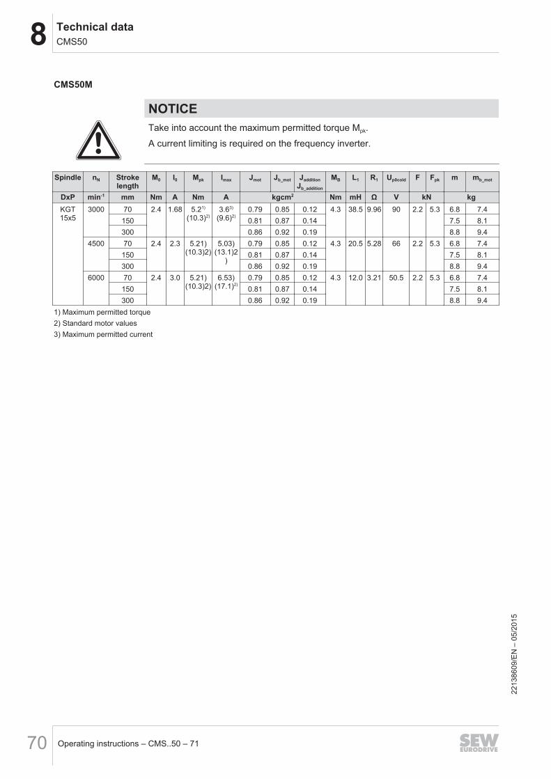
8 Technical dataCMS50
Operating instructions – CMS..50 – 7170
CMS50M
NOTICETake into account the maximum permitted torque Mpk.
A current limiting is required on the frequency inverter.
Spindle nN Strokelength
M0 I0 Mpk Imax Jmot Jb_mot JadditionJb_addition
MB L1 R1 Up0cold F Fpk m mb_mot
DxP min-1 mm Nm A Nm A kgcm2 Nm mH Ω V kN kgKGT15x5
3000 70 2.4 1.68 5.21)
(10.3)2)3.63)
(9.6)2)0.79 0.85 0.12 4.3 38.5 9.96 90 2.2 5.3 6.8 7.4
150 0.81 0.87 0.14 7.5 8.1300 0.86 0.92 0.19 8.8 9.4
4500 70 2.4 2.3 5.21)(10.3)2)
5.03)(13.1)2
)
0.79 0.85 0.12 4.3 20.5 5.28 66 2.2 5.3 6.8 7.4150 0.81 0.87 0.14 7.5 8.1300 0.86 0.92 0.19 8.8 9.4
6000 70 2.4 3.0 5.21)(10.3)2)
6.53)(17.1)2)
0.79 0.85 0.12 4.3 12.0 3.21 50.5 2.2 5.3 6.8 7.4150 0.81 0.87 0.14 7.5 8.1300 0.86 0.92 0.19 8.8 9.4
1) Maximum permitted torque2) Standard motor values3) Maximum permitted current
2213
8609
/EN
– 0
5/20
15

8Technical dataCMSB50, CSMB50
Operating instructions – CMS..50 – 71 71
8.4 CMSB50, CSMB508.4.1 Features
The table below shows the features.
Design Standard Optional
Degree of protection IP65
Motor protection KTY
Mounting position M0
Cooling Natural convection VR forced cooling fan/liquid cooling
Lubrication Oil bath lubrication Food grade lubricant
Spindle protection Smooth piston rod with sealing system
8.4.2 Technical data
INFORMATIONStroke length 70, 100, 150, 200, 300, 400 and 600 mm → nepk = 4500 min-1 (max.mechanical speed)
NOTICEAdhere to the maximum permitted torque Mpk or Mepk for electric cylinders of lengthM and L.
A current limiting is required on the frequency inverter.
2213
8609
/EN
– 0
5/20
15
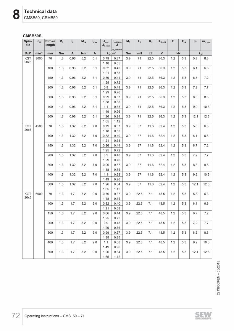
8 Technical dataCMSB50, CSMB50
Operating instructions – CMS..50 – 7172
CMSB50SSpin-dle
nN Strokelength
M0 I0 Mpk Imax JmotJb_mot
JadditionJ
b_addition
MB L1 R1 Up0cold F Fpk m mb_mot
DxP min-1 mm Nm A Nm A kgcm2 Nm mH Ω V kN kgKGT20x5
3000 70 1.3 0.96 5.2 5.1 0.79 0.37 3.9 71 22.5 86.3 1.2 5.3 5.8 6.31.18 0.65
100 1.3 0.96 5.2 5.1 0.82 0.40 3.9 71 22.5 86.3 1.2 5.3 6.1 6.61.21 0.68
150 1.3 0.96 5.2 5.1 0.86 0.44 3.9 71 22.5 86.3 1.2 5.3 6.7 7.21.25 0.72
200 1.3 0.96 5.2 5.1 0.9 0.48 3.9 71 22.5 86.3 1.2 5.3 7.2 7.71.29 0.76
300 1.3 0.96 5.2 5.1 0.99 0.57 3.9 71 22.5 86.3 1.2 5.3 8.3 8.81.38 0.85
400 1.3 0.96 5.2 5.1 1.1 0.68 3.9 71 22.5 86.3 1.2 5.3 9.9 10.51.49 0.96
600 1.3 0.96 5.2 5.1 1.26 0.84 3.9 71 22.5 86.3 1.2 5.3 12.1 12.61.65 1.12
KGT20x5
4500 70 1.3 1.32 5.2 7.0 0.79 0.37 3.9 37 11.6 62.4 1.2 5.3 5.8 6.31.18 0.65
100 1.3 1.32 5.2 7.0 0.82 0.40 3.9 37 11.6 62.4 1.2 5.3 6.1 6.61.21 0.68
150 1.3 1.32 5.2 7.0 0.86 0.44 3.9 37 11.6 62.4 1.2 5.3 6.7 7.21.25 0.72
200 1.3 1.32 5.2 7.0 0.9 0.48 3.9 37 11.6 62.4 1.2 5.3 7.2 7.71.29 0.76
300 1.3 1.32 5.2 7.0 0.99 0.57 3.9 37 11.6 62.4 1.2 5.3 8.3 8.81.38 0.85
400 1.3 1.32 5.2 7.0 1.1 0.68 3.9 37 11.6 62.4 1.2 5.3 9.9 10.51.49 0.96
600 1.3 1.32 5.2 7.0 1.26 0.84 3.9 37 11.6 62.4 1.2 5.3 12.1 12.61.65 1.12
KGT20x5
6000 70 1.3 1.7 5.2 9.0 0.79 0.37 3.9 22.5 7.1 48.5 1.2 5.3 5.8 6.31.18 0.65
100 1.3 1.7 5.2 9.0 0.82 0.40 3.9 22.5 7.1 48.5 1.2 5.3 6.1 6.61.21 0.68
150 1.3 1.7 5.2 9.0 0.86 0.44 3.9 22.5 7.1 48.5 1.2 5.3 6.7 7.21.25 0.72
200 1.3 1.7 5.2 9.0 0.9 0.48 3.9 22.5 7.1 48.5 1.2 5.3 7.2 7.71.29 0.76
300 1.3 1.7 5.2 9.0 0.99 0.57 3.9 22.5 7.1 48.5 1.2 5.3 8.3 8.81.38 0.85
400 1.3 1.7 5.2 9.0 1.1 0.68 3.9 22.5 7.1 48.5 1.2 5.3 9.9 10.51.49 0.96
600 1.3 1.7 5.2 9.0 1.26 0.84 3.9 22.5 7.1 48.5 1.2 5.3 12.1 12.61.65 1.12
2213
8609
/EN
– 0
5/20
15
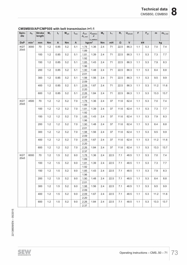
8Technical dataCMSB50, CSMB50
Operating instructions – CMS..50 – 71 73
CMSMB50/AP/CMP50S with belt transmission i=1:1Spin-dle
nN Strokelength
M0 I0 Mepk Imax JmotJb_mot
JadditionJ
b_addition
MB L1 R1 Up0cold F Fpk m mb_mot
DxP min-1 mm Nm A Nm A kgcm2 Nm mH Ω V kN kgKGT20x5
3000 70 1.2 0.85 5.2 5.1 1.78 1.36 2.4 71 22.5 86.3 1.1 5.3 7.0 7.41.89
100 1.2 0.85 5.2 5.1 1.81 1.39 2.4 71 22.5 86.3 1.1 5.3 7.3 7.71.92
150 1.2 0.85 5.2 5.1 1.85 1.43 2.4 71 22.5 86.3 1.1 5.3 7.9 8.31.96
200 1.2 0.85 5.2 5.1 1.90 1.48 2.4 71 22.5 86.3 1.1 5.3 8.4 8.82.01
300 1.2 0.85 5.2 5.1 1.98 1.56 2.4 71 22.5 86.3 1.1 5.3 9.5 9.92.09
400 1.2 0.85 5.2 5.1 2.09 1.67 2.4 71 22.5 86.3 1.1 5.3 11.2 11.62.20
600 1.2 0.85 5.2 5.1 2.26 1.84 2.4 71 22.5 86.3 1.1 5.3 13.3 13.72.37
KGT20x5
4500 70 1.2 1.2 5.2 7.0 1.78 1.36 2.4 37 11.6 62.4 1.1 5.3 7.0 7.41.89
100 1.2 1.2 5.2 7.0 1.81 1.39 2.4 37 11.6 62.4 1.1 5.3 7.3 7.71.92
150 1.2 1.2 5.2 7.0 1.85 1.43 2.4 37 11.6 62.4 1.1 5.3 7.9 8.31.96
200 1.2 1.2 5.2 7.0 1.90 1.48 2.4 37 11.6 62.4 1.1 5.3 8.4 8.82.01
300 1.2 1.2 5.2 7.0 1.98 1.56 2.4 37 11.6 62.4 1.1 5.3 9.5 9.92.09
400 1.2 1.2 5.2 7.0 2.09 1.67 2.4 37 11.6 62.4 1.1 5.3 11.2 11.62.20
600 1.2 1.2 5.2 7.0 2.26 1.84 2.4 37 11.6 62.4 1.1 5.3 13.3 13.72.37
KGT20x5
6000 70 1.2 1.5 5.2 9.0 1.78 1.36 2.4 22.5 7.1 48.5 1.1 5.3 7.0 7.41.89
100 1.2 1.5 5.2 9.0 1.81 1.39 2.4 22.5 7.1 48.5 1.1 5.3 7.3 7.71.92
150 1.2 1.5 5.2 9.0 1.85 1.43 2.4 22.5 7.1 48.5 1.1 5.3 7.9 8.31.96
200 1.2 1.5 5.2 9.0 1.90 1.48 2.4 22.5 7.1 48.5 1.1 5.3 8.4 8.82.01
300 1.2 1.5 5.2 9.0 1.98 1.56 2.4 22.5 7.1 48.5 1.1 5.3 9.5 9.92.09
400 1.2 1.5 5.2 9.0 2.09 1.67 2.4 22.5 7.1 48.5 1.1 5.3 11.2 11.62.20
600 1.2 1.5 5.2 9.0 2.26 1.84 2.4 22.5 7.1 48.5 1.1 5.3 13.3 13.72.37
2213
8609
/EN
– 0
5/20
15
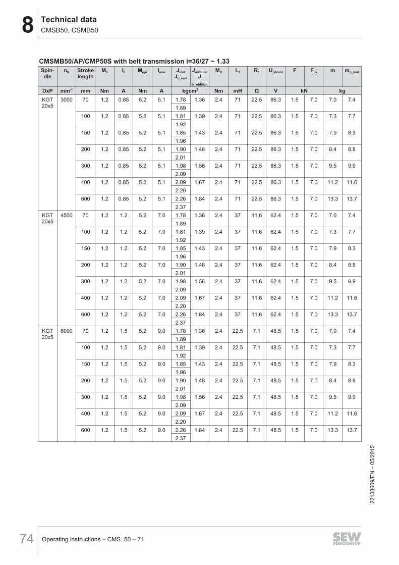
8 Technical dataCMSB50, CSMB50
Operating instructions – CMS..50 – 7174
CMSMB50/AP/CMP50S with belt transmission i=36/27 ~ 1.33Spin-dle
nN Strokelength
M0 I0 Mepk Imax JmotJb_mot
JadditionJ
b_addition
MB L1 R1 Up0cold F Fpk m mb_mot
DxP min-1 mm Nm A Nm A kgcm2 Nm mH Ω V kN kgKGT20x5
3000 70 1.2 0.85 5.2 5.1 1.78 1.36 2.4 71 22.5 86.3 1.5 7.0 7.0 7.41.89
100 1.2 0.85 5.2 5.1 1.81 1.39 2.4 71 22.5 86.3 1.5 7.0 7.3 7.71.92
150 1.2 0.85 5.2 5.1 1.85 1.43 2.4 71 22.5 86.3 1.5 7.0 7.9 8.31.96
200 1.2 0.85 5.2 5.1 1.90 1.48 2.4 71 22.5 86.3 1.5 7.0 8.4 8.82.01
300 1.2 0.85 5.2 5.1 1.98 1.56 2.4 71 22.5 86.3 1.5 7.0 9.5 9.92.09
400 1.2 0.85 5.2 5.1 2.09 1.67 2.4 71 22.5 86.3 1.5 7.0 11.2 11.62.20
600 1.2 0.85 5.2 5.1 2.26 1.84 2.4 71 22.5 86.3 1.5 7.0 13.3 13.72.37
KGT20x5
4500 70 1.2 1.2 5.2 7.0 1.78 1.36 2.4 37 11.6 62.4 1.5 7.0 7.0 7.41.89
100 1.2 1.2 5.2 7.0 1.81 1.39 2.4 37 11.6 62.4 1.5 7.0 7.3 7.71.92
150 1.2 1.2 5.2 7.0 1.85 1.43 2.4 37 11.6 62.4 1.5 7.0 7.9 8.31.96
200 1.2 1.2 5.2 7.0 1.90 1.48 2.4 37 11.6 62.4 1.5 7.0 8.4 8.82.01
300 1.2 1.2 5.2 7.0 1.98 1.56 2.4 37 11.6 62.4 1.5 7.0 9.5 9.92.09
400 1.2 1.2 5.2 7.0 2.09 1.67 2.4 37 11.6 62.4 1.5 7.0 11.2 11.62.20
600 1.2 1.2 5.2 7.0 2.26 1.84 2.4 37 11.6 62.4 1.5 7.0 13.3 13.72.37
KGT20x5
6000 70 1.2 1.5 5.2 9.0 1.78 1.36 2.4 22.5 7.1 48.5 1.5 7.0 7.0 7.41.89
100 1.2 1.5 5.2 9.0 1.81 1.39 2.4 22.5 7.1 48.5 1.5 7.0 7.3 7.71.92
150 1.2 1.5 5.2 9.0 1.85 1.43 2.4 22.5 7.1 48.5 1.5 7.0 7.9 8.31.96
200 1.2 1.5 5.2 9.0 1.90 1.48 2.4 22.5 7.1 48.5 1.5 7.0 8.4 8.82.01
300 1.2 1.5 5.2 9.0 1.98 1.56 2.4 22.5 7.1 48.5 1.5 7.0 9.5 9.92.09
400 1.2 1.5 5.2 9.0 2.09 1.67 2.4 22.5 7.1 48.5 1.5 7.0 11.2 11.62.20
600 1.2 1.5 5.2 9.0 2.26 1.84 2.4 22.5 7.1 48.5 1.5 7.0 13.3 13.72.37
2213
8609
/EN
– 0
5/20
15
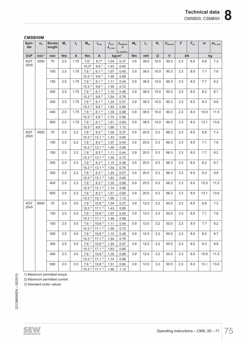
8Technical dataCMSB50, CSMB50
Operating instructions – CMS..50 – 71 75
CMSB50MSpin-dle
nN Strokelength
M0 I0 Mpk Imax JmotJb_mot
JadditionJ
b_addition
MB L1 R1 Up0cold F Fpk m mb_mot
DxP min-1 mm Nm A Nm A kgcm2 Nm mH Ω V kN kgKGT20x5
3000 70 2.5 1.75 7.61) 6.12) 1.04 0.37 3.9 38.5 10.0 90.3 2.3 8.0 6.8 7.310.33) 9.6 3) 1.43 0.65
100 2.5 1.75 7.6 1) 6.1 2) 1.07 0.40 3.9 38.5 10.0 90.3 2.3 8.0 7.1 7.610.3 3) 9.6 3) 1.46 0.68
150 2.5 1.75 7.6 1) 6.1 2) 1.11 0.44 3.9 38.5 10.0 90.3 2.3 8.0 7.7 8.210.3 3) 9.6 3) 1.50 0.72
200 2.5 1.75 7.6 1) 6.1 2) 1.15 0.48 3.9 38.5 10.0 90.3 2.3 8.0 8.2 8.710.3 3) 9.6 3) 1.54 0.76
300 2.5 1.75 7.6 1) 6.1 2) 1.24 0.57 3.9 38.5 10.0 90.3 2.3 8.0 9.3 9.810.3 3) 9.6 3) 1.63 0.85
400 2.5 1.75 7.6 1) 6.1 2) 1.35 0.68 3.9 38.5 10.0 90.3 2.3 8.0 10.9 11.510.3 3) 9.6 3) 1.74 0.96
600 2.5 1.75 7.6 1) 6.1 2) 1.51 0.84 3.9 38.5 10.0 90.3 2.3 8.0 13.1 13.610.3 3) 9.6 3) 1.90 1.12
KGT20x5
4500 70 2.5 2.2 7.6 1) 8.3 2) 1.04 0.37 3.9 20.5 5.3 66.3 2.3 8.0 6.8 7.310.3 3) 13.1 3) 1.43 0.65
100 2.5 2.2 7.6 1) 8.3 2) 1.07 0.40 3.9 20.5 5.3 66.3 2.3 8.0 7.1 7.610.3 3) 13.1 3) 1.46 0.68
150 2.5 2.2 7.6 1) 8.3 2) 1.11 0.44 3.9 20.5 5.3 66.3 2.3 8.0 7.7 8.210.3 3) 13.1 3) 1.50 0.72
200 2.5 2.2 7.6 1) 8.3 2) 1.15 0.48 3.9 20.5 5.3 66.3 2.3 8.0 8.2 8.710.3 3) 13.1 3) 1.54 0.76
300 2.5 2.2 7.6 1) 8.3 2) 1.24 0.57 3.9 20.5 5.3 66.3 2.3 8.0 9.3 9.810.3 3) 13.1 3) 1.63 0.85
400 2.5 2.2 7.6 1) 8.3 2) 1.35 0.68 3.9 20.5 5.3 66.3 2.3 8.0 10.9 11.510.3 3) 13.1 3) 1.74 0.96
600 2.5 2.2 7.6 1) 8.3 2) 1.51 0.84 3.9 20.5 5.3 66.3 2.3 8.0 13.1 13.610.3 3) 13.1 3) 1.90 1.12
KGT20x5
6000 70 2.5 3.0 7.6 1) 10.8 2) 1.04 0.37 3.9 12.0 3.2 50.5 2.3 8.0 6.8 7.310.3 3) 17.1 3) 1.43 0.65
100 2.5 3.0 7.6 1) 10.8 2) 1.07 0.40 3.9 12.0 3.2 50.5 2.3 8.0 7.1 7.610.3 3) 17.1 3) 1.46 0.68
150 2.5 3.0 7.6 1) 10.8 2) 1.11 0.44 3.9 12.0 3.2 50.5 2.3 8.0 7.7 8.210.3 3) 17.1 3) 1.50 0.72
200 2.5 3.0 7.6 1) 10.8 2) 1.15 0.48 3.9 12.0 3.2 50.5 2.3 8.0 8.2 8.710.3 3) 17.1 3) 1.54 0.76
300 2.5 3.0 7.6 1) 10.8 2) 1.24 0.57 3.9 12.0 3.2 50.5 2.3 8.0 9.3 9.810.3 3) 17.1 3) 1.63 0.85
400 2.5 3.0 7.6 1) 10.8 2) 1.35 0.68 3.9 12.0 3.2 50.5 2.3 8.0 10.9 11.510.3 3) 17.1 3) 1.74 0.96
600 2.5 3.0 7.6 1) 10.8 2) 1.51 0.84 3.9 12.0 3.2 50.5 2.3 8.0 13.1 13.610.3 3) 17.1 3) 1.90 1.12
1) Maximum permitted torque2) Maximum permitted current3) Standard motor values
2213
8609
/EN
– 0
5/20
15
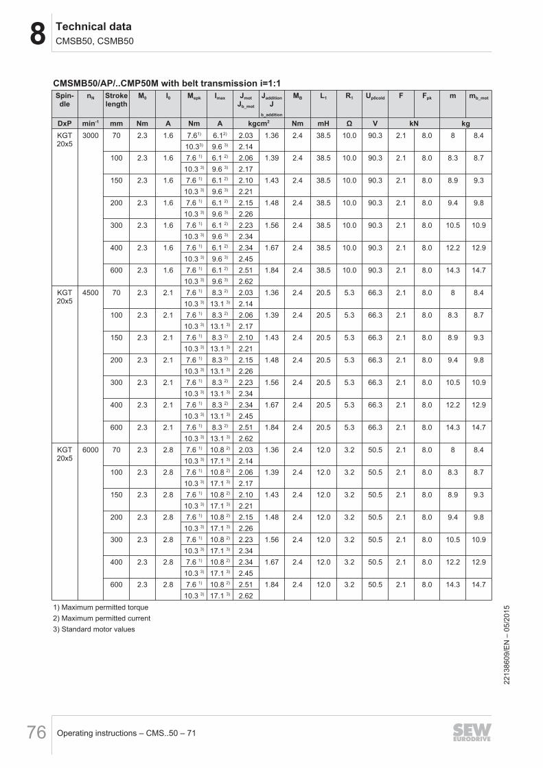
8 Technical dataCMSB50, CSMB50
Operating instructions – CMS..50 – 7176
CMSMB50/AP/..CMP50M with belt transmission i=1:1Spin-dle
nN Strokelength
M0 I0 Mepk Imax JmotJb_mot
JadditionJ
b_addition
MB L1 R1 Up0cold F Fpk m mb_mot
DxP min-1 mm Nm A Nm A kgcm2 Nm mH Ω V kN kgKGT20x5
3000 70 2.3 1.6 7.61) 6.12) 2.03 1.36 2.4 38.5 10.0 90.3 2.1 8.0 8 8.410.33) 9.6 3) 2.14
100 2.3 1.6 7.6 1) 6.1 2) 2.06 1.39 2.4 38.5 10.0 90.3 2.1 8.0 8.3 8.710.3 3) 9.6 3) 2.17
150 2.3 1.6 7.6 1) 6.1 2) 2.10 1.43 2.4 38.5 10.0 90.3 2.1 8.0 8.9 9.310.3 3) 9.6 3) 2.21
200 2.3 1.6 7.6 1) 6.1 2) 2.15 1.48 2.4 38.5 10.0 90.3 2.1 8.0 9.4 9.810.3 3) 9.6 3) 2.26
300 2.3 1.6 7.6 1) 6.1 2) 2.23 1.56 2.4 38.5 10.0 90.3 2.1 8.0 10.5 10.910.3 3) 9.6 3) 2.34
400 2.3 1.6 7.6 1) 6.1 2) 2.34 1.67 2.4 38.5 10.0 90.3 2.1 8.0 12.2 12.910.3 3) 9.6 3) 2.45
600 2.3 1.6 7.6 1) 6.1 2) 2.51 1.84 2.4 38.5 10.0 90.3 2.1 8.0 14.3 14.710.3 3) 9.6 3) 2.62
KGT20x5
4500 70 2.3 2.1 7.6 1) 8.3 2) 2.03 1.36 2.4 20.5 5.3 66.3 2.1 8.0 8 8.410.3 3) 13.1 3) 2.14
100 2.3 2.1 7.6 1) 8.3 2) 2.06 1.39 2.4 20.5 5.3 66.3 2.1 8.0 8.3 8.710.3 3) 13.1 3) 2.17
150 2.3 2.1 7.6 1) 8.3 2) 2.10 1.43 2.4 20.5 5.3 66.3 2.1 8.0 8.9 9.310.3 3) 13.1 3) 2.21
200 2.3 2.1 7.6 1) 8.3 2) 2.15 1.48 2.4 20.5 5.3 66.3 2.1 8.0 9.4 9.810.3 3) 13.1 3) 2.26
300 2.3 2.1 7.6 1) 8.3 2) 2.23 1.56 2.4 20.5 5.3 66.3 2.1 8.0 10.5 10.910.3 3) 13.1 3) 2.34
400 2.3 2.1 7.6 1) 8.3 2) 2.34 1.67 2.4 20.5 5.3 66.3 2.1 8.0 12.2 12.910.3 3) 13.1 3) 2.45
600 2.3 2.1 7.6 1) 8.3 2) 2.51 1.84 2.4 20.5 5.3 66.3 2.1 8.0 14.3 14.710.3 3) 13.1 3) 2.62
KGT20x5
6000 70 2.3 2.8 7.6 1) 10.8 2) 2.03 1.36 2.4 12.0 3.2 50.5 2.1 8.0 8 8.410.3 3) 17.1 3) 2.14
100 2.3 2.8 7.6 1) 10.8 2) 2.06 1.39 2.4 12.0 3.2 50.5 2.1 8.0 8.3 8.710.3 3) 17.1 3) 2.17
150 2.3 2.8 7.6 1) 10.8 2) 2.10 1.43 2.4 12.0 3.2 50.5 2.1 8.0 8.9 9.310.3 3) 17.1 3) 2.21
200 2.3 2.8 7.6 1) 10.8 2) 2.15 1.48 2.4 12.0 3.2 50.5 2.1 8.0 9.4 9.810.3 3) 17.1 3) 2.26
300 2.3 2.8 7.6 1) 10.8 2) 2.23 1.56 2.4 12.0 3.2 50.5 2.1 8.0 10.5 10.910.3 3) 17.1 3) 2.34
400 2.3 2.8 7.6 1) 10.8 2) 2.34 1.67 2.4 12.0 3.2 50.5 2.1 8.0 12.2 12.910.3 3) 17.1 3) 2.45
600 2.3 2.8 7.6 1) 10.8 2) 2.51 1.84 2.4 12.0 3.2 50.5 2.1 8.0 14.3 14.710.3 3) 17.1 3) 2.62
1) Maximum permitted torque2) Maximum permitted current3) Standard motor values
2213
8609
/EN
– 0
5/20
15
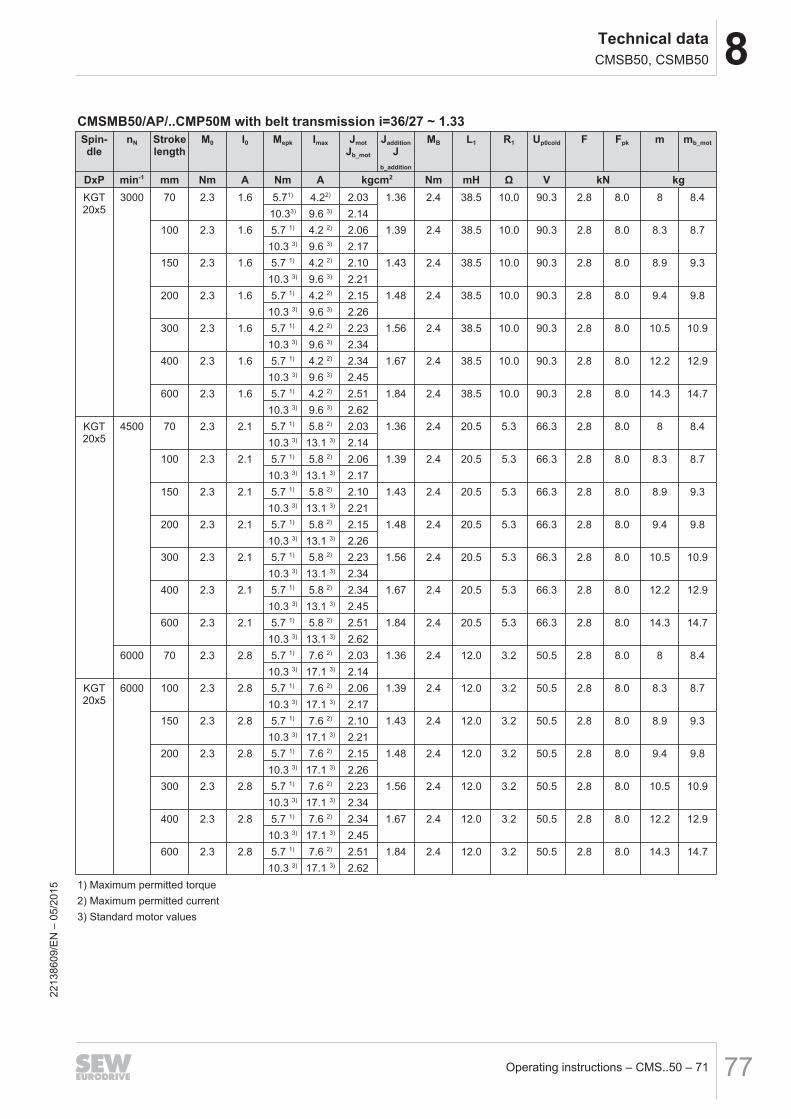
8Technical dataCMSB50, CSMB50
Operating instructions – CMS..50 – 71 77
CMSMB50/AP/..CMP50M with belt transmission i=36/27 ~ 1.33Spin-dle
nN Strokelength
M0 I0 Mepk Imax JmotJb_mot
JadditionJ
b_addition
MB L1 R1 Up0cold F Fpk m mb_mot
DxP min-1 mm Nm A Nm A kgcm2 Nm mH Ω V kN kgKGT20x5
3000 70 2.3 1.6 5.71) 4.22) 2.03 1.36 2.4 38.5 10.0 90.3 2.8 8.0 8 8.410.33) 9.6 3) 2.14
100 2.3 1.6 5.7 1) 4.2 2) 2.06 1.39 2.4 38.5 10.0 90.3 2.8 8.0 8.3 8.710.3 3) 9.6 3) 2.17
150 2.3 1.6 5.7 1) 4.2 2) 2.10 1.43 2.4 38.5 10.0 90.3 2.8 8.0 8.9 9.310.3 3) 9.6 3) 2.21
200 2.3 1.6 5.7 1) 4.2 2) 2.15 1.48 2.4 38.5 10.0 90.3 2.8 8.0 9.4 9.810.3 3) 9.6 3) 2.26
300 2.3 1.6 5.7 1) 4.2 2) 2.23 1.56 2.4 38.5 10.0 90.3 2.8 8.0 10.5 10.910.3 3) 9.6 3) 2.34
400 2.3 1.6 5.7 1) 4.2 2) 2.34 1.67 2.4 38.5 10.0 90.3 2.8 8.0 12.2 12.910.3 3) 9.6 3) 2.45
600 2.3 1.6 5.7 1) 4.2 2) 2.51 1.84 2.4 38.5 10.0 90.3 2.8 8.0 14.3 14.710.3 3) 9.6 3) 2.62
KGT20x5
4500 70 2.3 2.1 5.7 1) 5.8 2) 2.03 1.36 2.4 20.5 5.3 66.3 2.8 8.0 8 8.410.3 3) 13.1 3) 2.14
100 2.3 2.1 5.7 1) 5.8 2) 2.06 1.39 2.4 20.5 5.3 66.3 2.8 8.0 8.3 8.710.3 3) 13.1 3) 2.17
150 2.3 2.1 5.7 1) 5.8 2) 2.10 1.43 2.4 20.5 5.3 66.3 2.8 8.0 8.9 9.310.3 3) 13.1 3) 2.21
200 2.3 2.1 5.7 1) 5.8 2) 2.15 1.48 2.4 20.5 5.3 66.3 2.8 8.0 9.4 9.810.3 3) 13.1 3) 2.26
300 2.3 2.1 5.7 1) 5.8 2) 2.23 1.56 2.4 20.5 5.3 66.3 2.8 8.0 10.5 10.910.3 3) 13.1 3) 2.34
400 2.3 2.1 5.7 1) 5.8 2) 2.34 1.67 2.4 20.5 5.3 66.3 2.8 8.0 12.2 12.910.3 3) 13.1 3) 2.45
600 2.3 2.1 5.7 1) 5.8 2) 2.51 1.84 2.4 20.5 5.3 66.3 2.8 8.0 14.3 14.710.3 3) 13.1 3) 2.62
6000 70 2.3 2.8 5.7 1) 7.6 2) 2.03 1.36 2.4 12.0 3.2 50.5 2.8 8.0 8 8.410.3 3) 17.1 3) 2.14
KGT20x5
6000 100 2.3 2.8 5.7 1) 7.6 2) 2.06 1.39 2.4 12.0 3.2 50.5 2.8 8.0 8.3 8.710.3 3) 17.1 3) 2.17
150 2.3 2.8 5.7 1) 7.6 2) 2.10 1.43 2.4 12.0 3.2 50.5 2.8 8.0 8.9 9.310.3 3) 17.1 3) 2.21
200 2.3 2.8 5.7 1) 7.6 2) 2.15 1.48 2.4 12.0 3.2 50.5 2.8 8.0 9.4 9.810.3 3) 17.1 3) 2.26
300 2.3 2.8 5.7 1) 7.6 2) 2.23 1.56 2.4 12.0 3.2 50.5 2.8 8.0 10.5 10.910.3 3) 17.1 3) 2.34
400 2.3 2.8 5.7 1) 7.6 2) 2.34 1.67 2.4 12.0 3.2 50.5 2.8 8.0 12.2 12.910.3 3) 17.1 3) 2.45
600 2.3 2.8 5.7 1) 7.6 2) 2.51 1.84 2.4 12.0 3.2 50.5 2.8 8.0 14.3 14.710.3 3) 17.1 3) 2.62
1) Maximum permitted torque2) Maximum permitted current3) Standard motor values
2213
8609
/EN
– 0
5/20
15
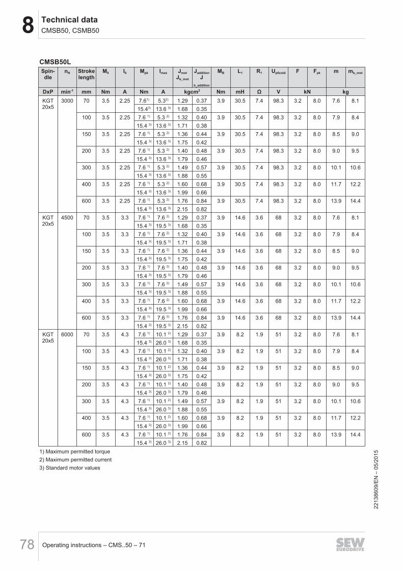
8 Technical dataCMSB50, CSMB50
Operating instructions – CMS..50 – 7178
CMSB50LSpin-dle
nN Strokelength
M0 I0 Mpk Imax JmotJb_mot
JadditionJ
b_addition
MB L1 R1 Up0cold F Fpk m mb_mot
DxP min-1 mm Nm A Nm A kgcm2 Nm mH Ω V kN kgKGT20x5
3000 70 3.5 2.25 7.61) 5.32) 1.29 0.37 3.9 30.5 7.4 98.3 3.2 8.0 7.6 8.115.43) 13.6 3) 1.68 0.35
100 3.5 2.25 7.6 1) 5.3 2) 1.32 0.40 3.9 30.5 7.4 98.3 3.2 8.0 7.9 8.415.4 3) 13.6 3) 1.71 0.38
150 3.5 2.25 7.6 1) 5.3 2) 1.36 0.44 3.9 30.5 7.4 98.3 3.2 8.0 8.5 9.015.4 3) 13.6 3) 1.75 0.42
200 3.5 2.25 7.6 1) 5.3 2) 1.40 0.48 3.9 30.5 7.4 98.3 3.2 8.0 9.0 9.515.4 3) 13.6 3) 1.79 0.46
300 3.5 2.25 7.6 1) 5.3 2) 1.49 0.57 3.9 30.5 7.4 98.3 3.2 8.0 10.1 10.615.4 3) 13.6 3) 1.88 0.55
400 3.5 2.25 7.6 1) 5.3 2) 1.60 0.68 3.9 30.5 7.4 98.3 3.2 8.0 11.7 12.215.4 3) 13.6 3) 1.99 0.66
600 3.5 2.25 7.6 1) 5.3 2) 1.76 0.84 3.9 30.5 7.4 98.3 3.2 8.0 13.9 14.415.4 3) 13.6 3) 2.15 0.82
KGT20x5
4500 70 3.5 3.3 7.6 1) 7.6 2) 1.29 0.37 3.9 14.6 3.6 68 3.2 8.0 7.6 8.115.4 3) 19.5 3) 1.68 0.35
100 3.5 3.3 7.6 1) 7.6 2) 1.32 0.40 3.9 14.6 3.6 68 3.2 8.0 7.9 8.415.4 3) 19.5 3) 1.71 0.38
150 3.5 3.3 7.6 1) 7.6 2) 1.36 0.44 3.9 14.6 3.6 68 3.2 8.0 8.5 9.015.4 3) 19.5 3) 1.75 0.42
200 3.5 3.3 7.6 1) 7.6 2) 1.40 0.48 3.9 14.6 3.6 68 3.2 8.0 9.0 9.515.4 3) 19.5 3) 1.79 0.46
300 3.5 3.3 7.6 1) 7.6 2) 1.49 0.57 3.9 14.6 3.6 68 3.2 8.0 10.1 10.615.4 3) 19.5 3) 1.88 0.55
400 3.5 3.3 7.6 1) 7.6 2) 1.60 0.68 3.9 14.6 3.6 68 3.2 8.0 11.7 12.215.4 3) 19.5 3) 1.99 0.66
600 3.5 3.3 7.6 1) 7.6 2) 1.76 0.84 3.9 14.6 3.6 68 3.2 8.0 13.9 14.415.4 3) 19.5 3) 2.15 0.82
KGT20x5
6000 70 3.5 4.3 7.6 1) 10.1 2) 1.29 0.37 3.9 8.2 1.9 51 3.2 8.0 7.6 8.115.4 3) 26.0 3) 1.68 0.35
100 3.5 4.3 7.6 1) 10.1 2) 1.32 0.40 3.9 8.2 1.9 51 3.2 8.0 7.9 8.415.4 3) 26.0 3) 1.71 0.38
150 3.5 4.3 7.6 1) 10.1 2) 1.36 0.44 3.9 8.2 1.9 51 3.2 8.0 8.5 9.015.4 3) 26.0 3) 1.75 0.42
200 3.5 4.3 7.6 1) 10.1 2) 1.40 0.48 3.9 8.2 1.9 51 3.2 8.0 9.0 9.515.4 3) 26.0 3) 1.79 0.46
300 3.5 4.3 7.6 1) 10.1 2) 1.49 0.57 3.9 8.2 1.9 51 3.2 8.0 10.1 10.615.4 3) 26.0 3) 1.88 0.55
400 3.5 4.3 7.6 1) 10.1 2) 1.60 0.68 3.9 8.2 1.9 51 3.2 8.0 11.7 12.215.4 3) 26.0 3) 1.99 0.66
600 3.5 4.3 7.6 1) 10.1 2) 1.76 0.84 3.9 8.2 1.9 51 3.2 8.0 13.9 14.415.4 3) 26.0 3) 2.15 0.82
1) Maximum permitted torque2) Maximum permitted current3) Standard motor values
2213
8609
/EN
– 0
5/20
15
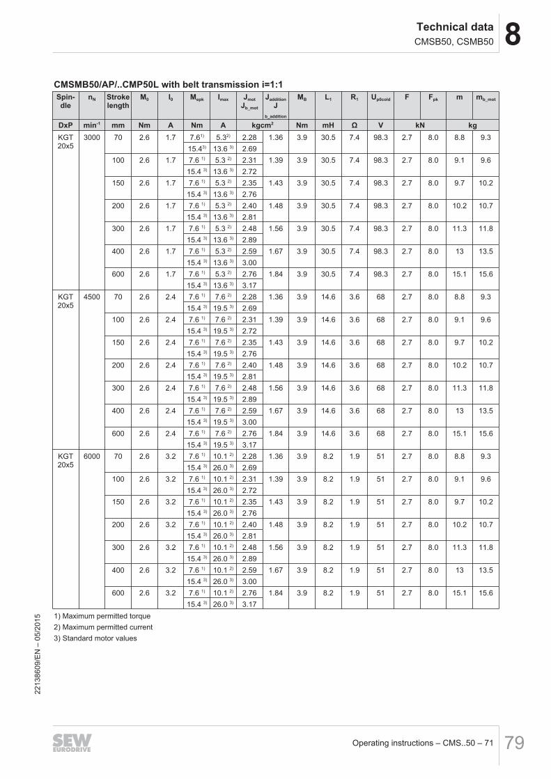
8Technical dataCMSB50, CSMB50
Operating instructions – CMS..50 – 71 79
CMSMB50/AP/..CMP50L with belt transmission i=1:1Spin-dle
nN Strokelength
M0 I0 Mepk Imax JmotJb_mot
JadditionJ
b_addition
MB L1 R1 Up0cold F Fpk m mb_mot
DxP min-1 mm Nm A Nm A kgcm2 Nm mH Ω V kN kgKGT20x5
3000 70 2.6 1.7 7.61) 5.32) 2.28 1.36 3.9 30.5 7.4 98.3 2.7 8.0 8.8 9.315.43) 13.6 3) 2.69
100 2.6 1.7 7.6 1) 5.3 2) 2.31 1.39 3.9 30.5 7.4 98.3 2.7 8.0 9.1 9.615.4 3) 13.6 3) 2.72
150 2.6 1.7 7.6 1) 5.3 2) 2.35 1.43 3.9 30.5 7.4 98.3 2.7 8.0 9.7 10.215.4 3) 13.6 3) 2.76
200 2.6 1.7 7.6 1) 5.3 2) 2.40 1.48 3.9 30.5 7.4 98.3 2.7 8.0 10.2 10.715.4 3) 13.6 3) 2.81
300 2.6 1.7 7.6 1) 5.3 2) 2.48 1.56 3.9 30.5 7.4 98.3 2.7 8.0 11.3 11.815.4 3) 13.6 3) 2.89
400 2.6 1.7 7.6 1) 5.3 2) 2.59 1.67 3.9 30.5 7.4 98.3 2.7 8.0 13 13.515.4 3) 13.6 3) 3.00
600 2.6 1.7 7.6 1) 5.3 2) 2.76 1.84 3.9 30.5 7.4 98.3 2.7 8.0 15.1 15.615.4 3) 13.6 3) 3.17
KGT20x5
4500 70 2.6 2.4 7.6 1) 7.6 2) 2.28 1.36 3.9 14.6 3.6 68 2.7 8.0 8.8 9.315.4 3) 19.5 3) 2.69
100 2.6 2.4 7.6 1) 7.6 2) 2.31 1.39 3.9 14.6 3.6 68 2.7 8.0 9.1 9.615.4 3) 19.5 3) 2.72
150 2.6 2.4 7.6 1) 7.6 2) 2.35 1.43 3.9 14.6 3.6 68 2.7 8.0 9.7 10.215.4 3) 19.5 3) 2.76
200 2.6 2.4 7.6 1) 7.6 2) 2.40 1.48 3.9 14.6 3.6 68 2.7 8.0 10.2 10.715.4 3) 19.5 3) 2.81
300 2.6 2.4 7.6 1) 7.6 2) 2.48 1.56 3.9 14.6 3.6 68 2.7 8.0 11.3 11.815.4 3) 19.5 3) 2.89
400 2.6 2.4 7.6 1) 7.6 2) 2.59 1.67 3.9 14.6 3.6 68 2.7 8.0 13 13.515.4 3) 19.5 3) 3.00
600 2.6 2.4 7.6 1) 7.6 2) 2.76 1.84 3.9 14.6 3.6 68 2.7 8.0 15.1 15.615.4 3) 19.5 3) 3.17
KGT20x5
6000 70 2.6 3.2 7.6 1) 10.1 2) 2.28 1.36 3.9 8.2 1.9 51 2.7 8.0 8.8 9.315.4 3) 26.0 3) 2.69
100 2.6 3.2 7.6 1) 10.1 2) 2.31 1.39 3.9 8.2 1.9 51 2.7 8.0 9.1 9.615.4 3) 26.0 3) 2.72
150 2.6 3.2 7.6 1) 10.1 2) 2.35 1.43 3.9 8.2 1.9 51 2.7 8.0 9.7 10.215.4 3) 26.0 3) 2.76
200 2.6 3.2 7.6 1) 10.1 2) 2.40 1.48 3.9 8.2 1.9 51 2.7 8.0 10.2 10.715.4 3) 26.0 3) 2.81
300 2.6 3.2 7.6 1) 10.1 2) 2.48 1.56 3.9 8.2 1.9 51 2.7 8.0 11.3 11.815.4 3) 26.0 3) 2.89
400 2.6 3.2 7.6 1) 10.1 2) 2.59 1.67 3.9 8.2 1.9 51 2.7 8.0 13 13.515.4 3) 26.0 3) 3.00
600 2.6 3.2 7.6 1) 10.1 2) 2.76 1.84 3.9 8.2 1.9 51 2.7 8.0 15.1 15.615.4 3) 26.0 3) 3.17
1) Maximum permitted torque2) Maximum permitted current3) Standard motor values
2213
8609
/EN
– 0
5/20
15
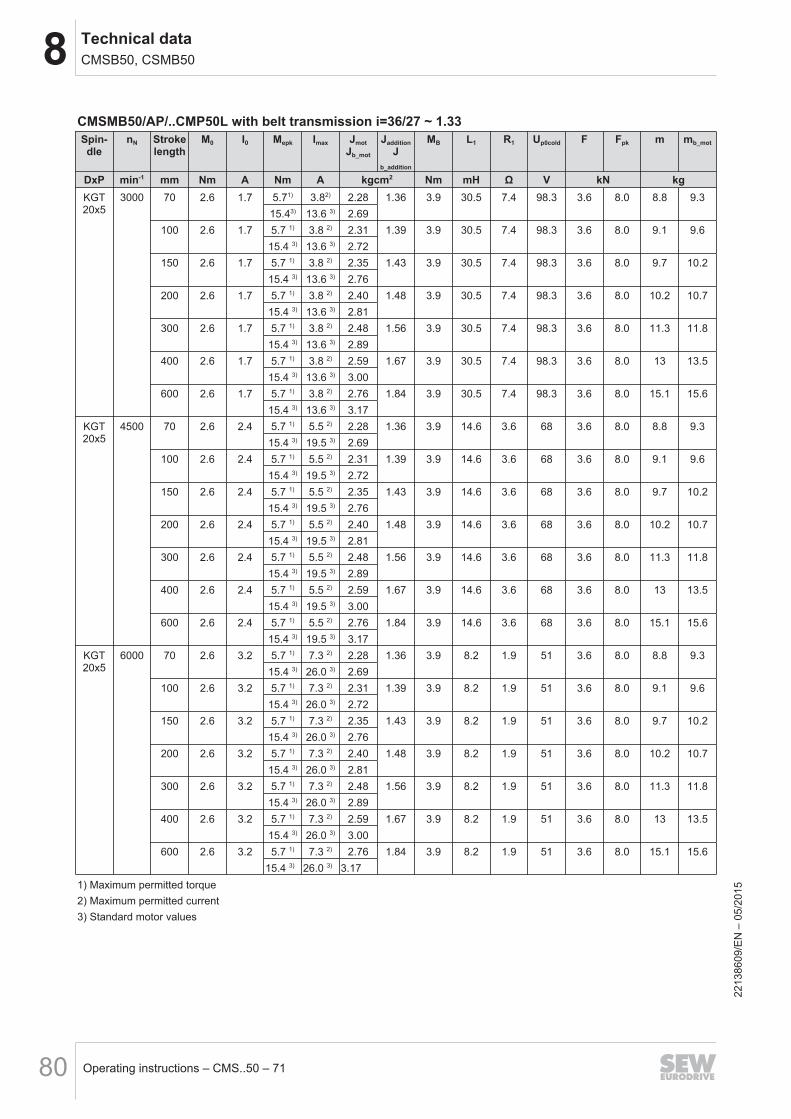
8 Technical dataCMSB50, CSMB50
Operating instructions – CMS..50 – 7180
CMSMB50/AP/..CMP50L with belt transmission i=36/27 ~ 1.33Spin-dle
nN Strokelength
M0 I0 Mepk Imax JmotJb_mot
JadditionJ
b_addition
MB L1 R1 Up0cold F Fpk m mb_mot
DxP min-1 mm Nm A Nm A kgcm2 Nm mH Ω V kN kgKGT20x5
3000 70 2.6 1.7 5.71) 3.82) 2.28 1.36 3.9 30.5 7.4 98.3 3.6 8.0 8.8 9.315.43) 13.6 3) 2.69
100 2.6 1.7 5.7 1) 3.8 2) 2.31 1.39 3.9 30.5 7.4 98.3 3.6 8.0 9.1 9.615.4 3) 13.6 3) 2.72
150 2.6 1.7 5.7 1) 3.8 2) 2.35 1.43 3.9 30.5 7.4 98.3 3.6 8.0 9.7 10.215.4 3) 13.6 3) 2.76
200 2.6 1.7 5.7 1) 3.8 2) 2.40 1.48 3.9 30.5 7.4 98.3 3.6 8.0 10.2 10.715.4 3) 13.6 3) 2.81
300 2.6 1.7 5.7 1) 3.8 2) 2.48 1.56 3.9 30.5 7.4 98.3 3.6 8.0 11.3 11.815.4 3) 13.6 3) 2.89
400 2.6 1.7 5.7 1) 3.8 2) 2.59 1.67 3.9 30.5 7.4 98.3 3.6 8.0 13 13.515.4 3) 13.6 3) 3.00
600 2.6 1.7 5.7 1) 3.8 2) 2.76 1.84 3.9 30.5 7.4 98.3 3.6 8.0 15.1 15.615.4 3) 13.6 3) 3.17
KGT20x5
4500 70 2.6 2.4 5.7 1) 5.5 2) 2.28 1.36 3.9 14.6 3.6 68 3.6 8.0 8.8 9.315.4 3) 19.5 3) 2.69
100 2.6 2.4 5.7 1) 5.5 2) 2.31 1.39 3.9 14.6 3.6 68 3.6 8.0 9.1 9.615.4 3) 19.5 3) 2.72
150 2.6 2.4 5.7 1) 5.5 2) 2.35 1.43 3.9 14.6 3.6 68 3.6 8.0 9.7 10.215.4 3) 19.5 3) 2.76
200 2.6 2.4 5.7 1) 5.5 2) 2.40 1.48 3.9 14.6 3.6 68 3.6 8.0 10.2 10.715.4 3) 19.5 3) 2.81
300 2.6 2.4 5.7 1) 5.5 2) 2.48 1.56 3.9 14.6 3.6 68 3.6 8.0 11.3 11.815.4 3) 19.5 3) 2.89
400 2.6 2.4 5.7 1) 5.5 2) 2.59 1.67 3.9 14.6 3.6 68 3.6 8.0 13 13.515.4 3) 19.5 3) 3.00
600 2.6 2.4 5.7 1) 5.5 2) 2.76 1.84 3.9 14.6 3.6 68 3.6 8.0 15.1 15.615.4 3) 19.5 3) 3.17
KGT20x5
6000 70 2.6 3.2 5.7 1) 7.3 2) 2.28 1.36 3.9 8.2 1.9 51 3.6 8.0 8.8 9.315.4 3) 26.0 3) 2.69
100 2.6 3.2 5.7 1) 7.3 2) 2.31 1.39 3.9 8.2 1.9 51 3.6 8.0 9.1 9.615.4 3) 26.0 3) 2.72
150 2.6 3.2 5.7 1) 7.3 2) 2.35 1.43 3.9 8.2 1.9 51 3.6 8.0 9.7 10.215.4 3) 26.0 3) 2.76
200 2.6 3.2 5.7 1) 7.3 2) 2.40 1.48 3.9 8.2 1.9 51 3.6 8.0 10.2 10.715.4 3) 26.0 3) 2.81
300 2.6 3.2 5.7 1) 7.3 2) 2.48 1.56 3.9 8.2 1.9 51 3.6 8.0 11.3 11.815.4 3) 26.0 3) 2.89
400 2.6 3.2 5.7 1) 7.3 2) 2.59 1.67 3.9 8.2 1.9 51 3.6 8.0 13 13.515.4 3) 26.0 3) 3.00
600 2.6 3.2 5.7 1) 7.3 2) 2.76 1.84 3.9 8.2 1.9 51 3.6 8.0 15.1 15.615.4 3) 26.0 3) 3.17
1) Maximum permitted torque2) Maximum permitted current3) Standard motor values
2213
8609
/EN
– 0
5/20
15
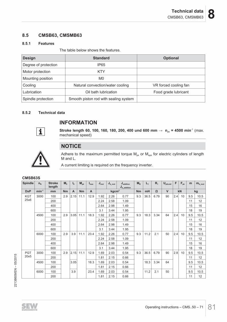
8Technical dataCMSB63, CMSMB63
Operating instructions – CMS..50 – 71 81
8.5 CMSB63, CMSMB638.5.1 Features
The table below shows the features.
Design Standard Optional
Degree of protection IP65
Motor protection KTY
Mounting position M0
Cooling Natural convection/water cooling VR forced cooling fan
Lubrication Oil bath lubrication Food grade lubricant
Spindle protection Smooth piston rod with sealing system
8.5.2 Technical data
INFORMATIONStroke length 60, 100, 160, 180, 200, 400 und 600 mm → npk = 4500 min-1 (max.mechanical speed)
NOTICEAdhere to the maximum permitted torque Mpk or Mepk for electric cylinders of lengthM and L.
A current limiting is required on the frequency inverter.
CMSB63SSpindle nN Stroke
lengthM0 I0 Mpk Imax Jmot Jb_mot Jaddition
Jb_addition
MB L1 R1 Up0cold F Fpk m mb_mot
DxP min-1 mm Nm A Nm A kgcm2 Nm mH Ω V kN kgKGT25x6
3000 100 2.9 2.15 11.1 12.9 1.92 2.26 0.77 9.3 36.5 6.79 90 2.4 10 9.5 10.5200 2.24 2.58 1.09 11 12400 2.64 2.98 1.49 15 16600 3.1 3.44 1.95 18 19
4500 100 2.9 3.05 11.1 18.3 1.92 2.26 0.77 9.3 18.3 3.34 64 2.4 10 9.5 10.5200 2.24 2.58 1.09 11 12400 2.64 2.98 1.49 15 16600 3.1 3.44 1.95 18 19
6000 100 2.9 3.9 11.1 23.4 1.92 2.26 0.77 9.3 11.2 2.1 50 2.4 10 9.5 10.5200 2.24 2.58 1.09 11 12400 2.64 2.98 1.49 15 16600 3.1 3.44 1.95 18 19
PGT20x5
3000 100 2.9 2.15 11.1 12.9 1.69 2.03 0.54 9.3 36.5 6.79 90 2.8 10 9.5 10.5200 1.81 2.15 0.66 11 12
4500 100 3.05 18.3 1.69 2.03 0.54 18.3 3.34 64 9.5 10.5200 1.81 2.15 0.66 11 12
6000 100 3.9 23.4 1.69 2.03 0.54 11.2 2.1 50 9.5 10.5200 1.81 2.15 0.66 11 12
2213
8609
/EN
– 0
5/20
15
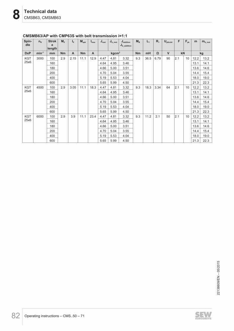
8 Technical dataCMSB63, CMSMB63
Operating instructions – CMS..50 – 7182
CMSMB63/AP with CMP63S with belt transmission i=1:1Spin-dle
nN Stroke
length
M0 I0 Mepk Imax Jmot Jb_mot JadditionJb_addition
MB L1 R1 Up0cold F Fpk m mb_mot
DxP min-1 mm Nm A Nm A kgcm2 Nm mH Ω V kN kgKGT25x6
3000 100 2.9 2.15 11.1 12.9 4.47 4.81 3.32 9.3 36.5 6.79 90 2.1 10 12.2 13.2160 4.64 4.95 3.46 13.1 14.1180 4.66 5.00 3.51 13.6 14.6200 4.70 5.04 3.55 14.4 15.4400 5.19 5.53 4.04 18.0 19.0600 5.65 5.99 4.50 21.3 22.3
KGT25x6
4500 100 2.9 3.05 11.1 18.3 4.47 4.81 3.32 9.3 18.3 3.34 64 2.1 10 12.2 13.2160 4.64 4.95 3.46 13.1 14.1180 4.66 5.00 3.51 13.6 14.6200 4.70 5.04 3.55 14.4 15.4400 5.19 5.53 4.04 18.0 19.0600 5.65 5.99 4.50 21.3 22.3
KGT25x6
6000 100 2.9 3.9 11.1 23.4 4.47 4.81 3.32 9.3 11.2 2.1 50 2.1 10 12.2 13.2160 4.64 4.95 3.46 13.1 14.1180 4.66 5.00 3.51 13.6 14.6200 4.70 5.04 3.55 14.4 15.4400 5.19 5.53 4.04 18.0 19.0600 5.65 5.99 4.50 21.3 22.3
2213
8609
/EN
– 0
5/20
15
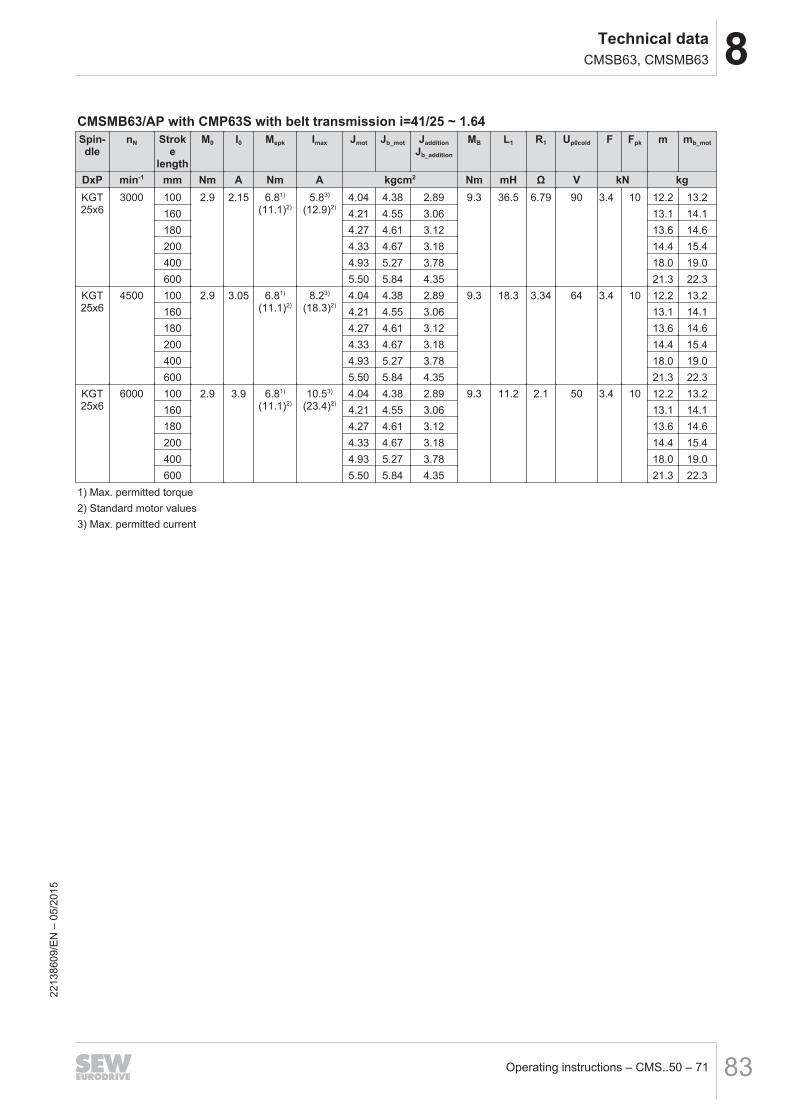
8Technical dataCMSB63, CMSMB63
Operating instructions – CMS..50 – 71 83
CMSMB63/AP with CMP63S with belt transmission i=41/25 ~ 1.64Spin-dle
nN Stroke
length
M0 I0 Mepk Imax Jmot Jb_mot JadditionJb_addition
MB L1 R1 Up0cold F Fpk m mb_mot
DxP min-1 mm Nm A Nm A kgcm2 Nm mH Ω V kN kgKGT25x6
3000 100 2.9 2.15 6.81)
(11.1)2)5.83)
(12.9)2)4.04 4.38 2.89 9.3 36.5 6.79 90 3.4 10 12.2 13.2
160 4.21 4.55 3.06 13.1 14.1180 4.27 4.61 3.12 13.6 14.6200 4.33 4.67 3.18 14.4 15.4400 4.93 5.27 3.78 18.0 19.0600 5.50 5.84 4.35 21.3 22.3
KGT25x6
4500 100 2.9 3.05 6.81)
(11.1)2)8.23)
(18.3)2)4.04 4.38 2.89 9.3 18.3 3.34 64 3.4 10 12.2 13.2
160 4.21 4.55 3.06 13.1 14.1180 4.27 4.61 3.12 13.6 14.6200 4.33 4.67 3.18 14.4 15.4400 4.93 5.27 3.78 18.0 19.0600 5.50 5.84 4.35 21.3 22.3
KGT25x6
6000 100 2.9 3.9 6.81)
(11.1)2)10.53)
(23.4)2)4.04 4.38 2.89 9.3 11.2 2.1 50 3.4 10 12.2 13.2
160 4.21 4.55 3.06 13.1 14.1180 4.27 4.61 3.12 13.6 14.6200 4.33 4.67 3.18 14.4 15.4400 4.93 5.27 3.78 18.0 19.0600 5.50 5.84 4.35 21.3 22.3
1) Max. permitted torque2) Standard motor values3) Max. permitted current
2213
8609
/EN
– 0
5/20
15
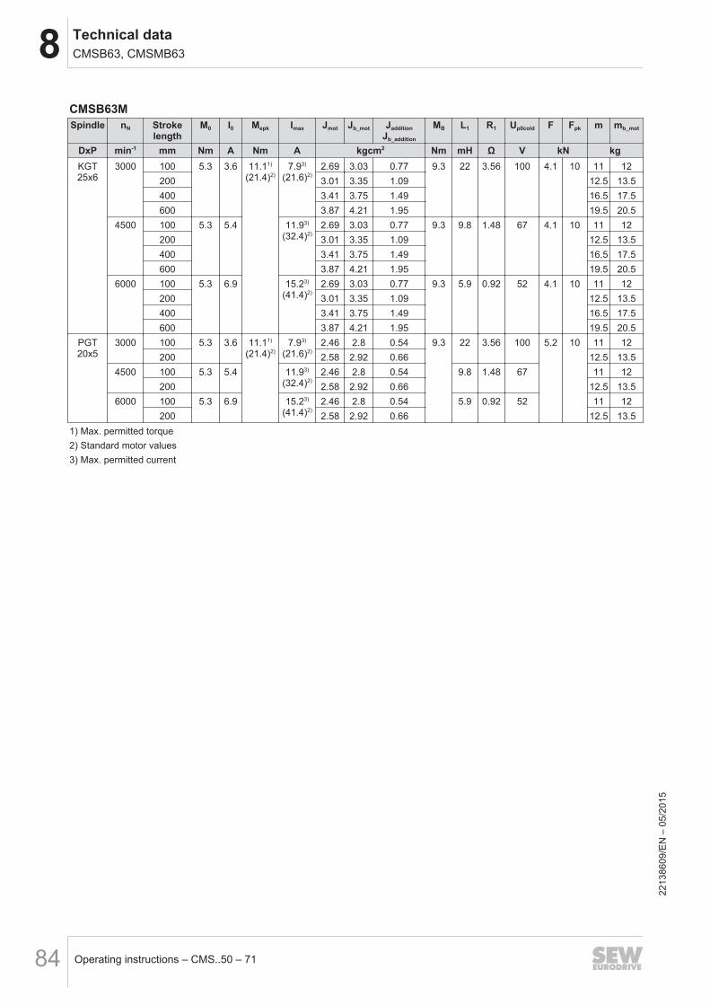
8 Technical dataCMSB63, CMSMB63
Operating instructions – CMS..50 – 7184
CMSB63MSpindle nN Stroke
lengthM0 I0 Mepk Imax Jmot Jb_mot Jaddition
Jb_addition
MB L1 R1 Up0cold F Fpk m mb_mot
DxP min-1 mm Nm A Nm A kgcm2 Nm mH Ω V kN kgKGT25x6
3000 100 5.3 3.6 11.11)
(21.4)2)7.93)
(21.6)2)2.69 3.03 0.77 9.3 22 3.56 100 4.1 10 11 12
200 3.01 3.35 1.09 12.5 13.5400 3.41 3.75 1.49 16.5 17.5600 3.87 4.21 1.95 19.5 20.5
4500 100 5.3 5.4 11.93)
(32.4)2)2.69 3.03 0.77 9.3 9.8 1.48 67 4.1 10 11 12
200 3.01 3.35 1.09 12.5 13.5400 3.41 3.75 1.49 16.5 17.5600 3.87 4.21 1.95 19.5 20.5
6000 100 5.3 6.9 15.23)
(41.4)2)2.69 3.03 0.77 9.3 5.9 0.92 52 4.1 10 11 12
200 3.01 3.35 1.09 12.5 13.5400 3.41 3.75 1.49 16.5 17.5600 3.87 4.21 1.95 19.5 20.5
PGT20x5
3000 100 5.3 3.6 11.11)
(21.4)2)7.93)
(21.6)2)2.46 2.8 0.54 9.3 22 3.56 100 5.2 10 11 12
200 2.58 2.92 0.66 12.5 13.54500 100 5.3 5.4 11.93)
(32.4)2)2.46 2.8 0.54 9.8 1.48 67 11 12
200 2.58 2.92 0.66 12.5 13.56000 100 5.3 6.9 15.23)
(41.4)2)2.46 2.8 0.54 5.9 0.92 52 11 12
200 2.58 2.92 0.66 12.5 13.51) Max. permitted torque2) Standard motor values3) Max. permitted current
2213
8609
/EN
– 0
5/20
15

8Technical dataCMSB63, CMSMB63
Operating instructions – CMS..50 – 71 85
CMSMB63/AP with CMP63M with belt transmission i=1:1Spin-dle
nN Strokelength
M0 I0 Mepk Imax Jmot Jb_mot JadditionJb_addition
MB L1 R1 Up0cold F Fpk m mb_mot
DxP min-1 mm Nm A Nm A kgcm2 Nm mH Ω V kN kgKGT25x6
3000 100 5.3 3.6 11.11)
(21.4)2)7.93)
(21.6)2)5.24 5.58 3.32 9.3 22 3.56 100 3.5 13.9 14.9
160 5.38 5.72 3.42 14.8 15.8180 5.43 5.77 3.51 15.3 16.3200 5.47 5.81 3.55 16.1 17.1400 5.96 6.30 4.04 19.7 20.7600 6.42 6.76 4.50 23.0 24.0
KGT25x6
4500 100 5.3 5.4 11.11)
(21.4)2)11.93)
(32.4)2)5.24 5.58 3.32 9.3 9.8 1.48 67 3.5 10 13.9 14.9
160 5.38 5.72 3.42 14.8 15.8180 5.43 5.77 3.51 15.3 16.3200 5.47 5.81 3.55 16.1 17.1400 5.96 6.30 4.04 19.7 20.7600 6.42 6.76 4.50 23.0 24.0
KGT25x6
6000 100 5.3 6.9 11.11)
(21.4)2)15.23)
(41.4)2)5.24 5.58 3.32 9.3 5.9 3.56 52 3.5 10 13.9 14.9
160 5.38 5.72 3.42 14.8 15.8180 5.43 5.77 3.51 15.3 16.3200 5.47 5.81 3.55 16.1 17.1400 5.96 6.30 4.04 19.7 20.7600 6.42 6.76 4.50 23.0 24.0
1) Max. permitted torque2) Standard motor values3) Max. permitted current
2213
8609
/EN
– 0
5/20
15
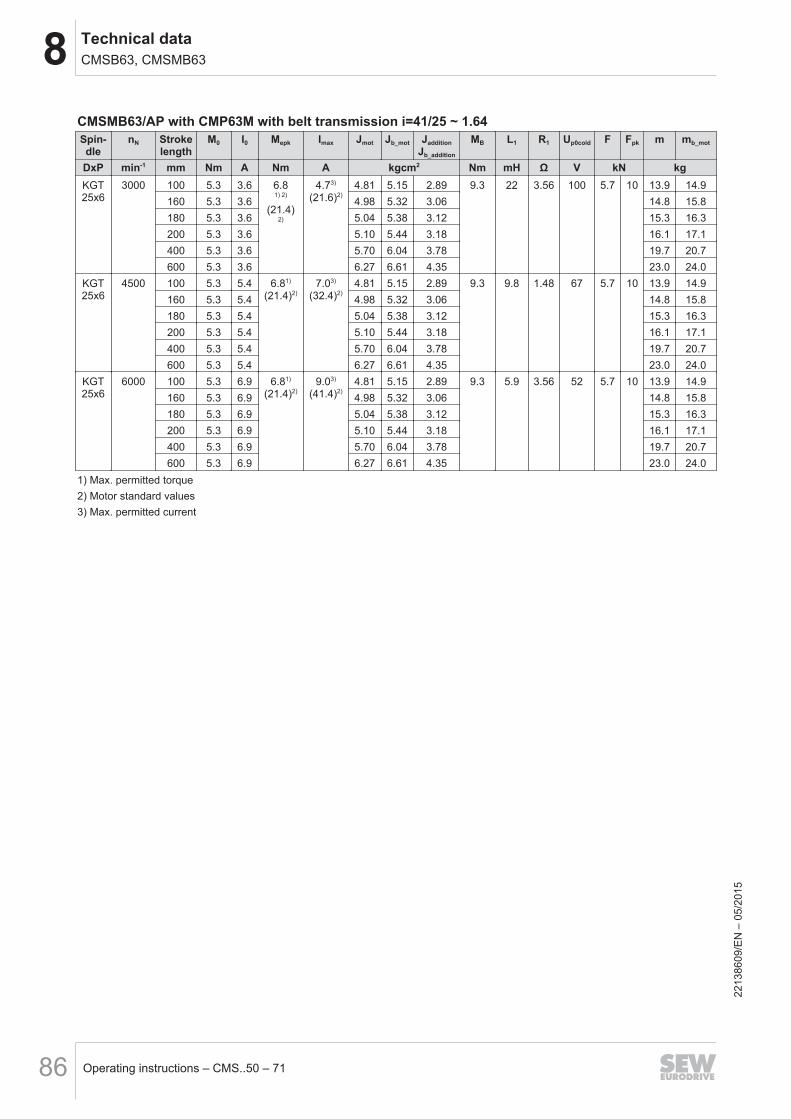
8 Technical dataCMSB63, CMSMB63
Operating instructions – CMS..50 – 7186
CMSMB63/AP with CMP63M with belt transmission i=41/25 ~ 1.64Spin-dle
nN Strokelength
M0 I0 Mepk Imax Jmot Jb_mot JadditionJb_addition
MB L1 R1 Up0cold F Fpk m mb_mot
DxP min-1 mm Nm A Nm A kgcm2 Nm mH Ω V kN kgKGT25x6
3000 100 5.3 3.6 6.81) 2)
(21.4)2)
4.73)
(21.6)2)4.81 5.15 2.89 9.3 22 3.56 100 5.7 10 13.9 14.9
160 5.3 3.6 4.98 5.32 3.06 14.8 15.8180 5.3 3.6 5.04 5.38 3.12 15.3 16.3200 5.3 3.6 5.10 5.44 3.18 16.1 17.1400 5.3 3.6 5.70 6.04 3.78 19.7 20.7600 5.3 3.6 6.27 6.61 4.35 23.0 24.0
KGT25x6
4500 100 5.3 5.4 6.81)
(21.4)2)7.03)
(32.4)2)4.81 5.15 2.89 9.3 9.8 1.48 67 5.7 10 13.9 14.9
160 5.3 5.4 4.98 5.32 3.06 14.8 15.8180 5.3 5.4 5.04 5.38 3.12 15.3 16.3200 5.3 5.4 5.10 5.44 3.18 16.1 17.1400 5.3 5.4 5.70 6.04 3.78 19.7 20.7600 5.3 5.4 6.27 6.61 4.35 23.0 24.0
KGT25x6
6000 100 5.3 6.9 6.81)
(21.4)2)9.03)
(41.4)2)4.81 5.15 2.89 9.3 5.9 3.56 52 5.7 10 13.9 14.9
160 5.3 6.9 4.98 5.32 3.06 14.8 15.8180 5.3 6.9 5.04 5.38 3.12 15.3 16.3200 5.3 6.9 5.10 5.44 3.18 16.1 17.1400 5.3 6.9 5.70 6.04 3.78 19.7 20.7600 5.3 6.9 6.27 6.61 4.35 23.0 24.0
1) Max. permitted torque2) Motor standard values3) Max. permitted current
2213
8609
/EN
– 0
5/20
15
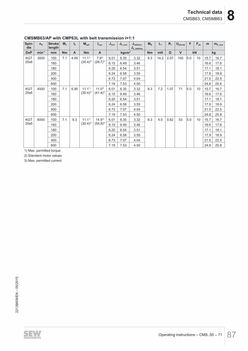
8Technical dataCMSB63, CMSMB63
Operating instructions – CMS..50 – 71 87
CMSMB63/AP with CMP63L with belt transmission i=1:1Spin-dle
nN Strokelength
M0 I0 Mepk Imax Jmot Jb_mot JadditionJb_addition
MB L1 R1 Up0cold F Fpk m mb_mot
DxP min-1 mm Nm A Nm A kgcm2 Nm mH Ω V kN kgKGT25x6
3000 100 7.1 4.95 11.11)
(30.4)2)7.93)
(29.7)2)6.01 6.35 3.32 9.3 14.2 2.07 100 5.0 10 15.7 16.7
160 6.15 6.49 3.46 16.6 17.6180 6.20 6.54 3.51 17.1 18.1200 6.24 6.58 3.55 17.9 18.9400 6.73 7.07 4.04 21.5 22.5600 7.19 7.53 4.50 24.8 25.8
KGT25x6
4500 100 7.1 6.90 11.11)
(30.4)2)11.03)
(41.4)2)6.01 6.35 3.32 9.3 7.2 1.07 71 5.0 10 15.7 16.7
160 6.15 6.49 3.46 16.6 17.6180 6.20 6.54 3.51 17.1 18.1200 6.24 6.58 3.55 17.9 18.9400 6.73 7.07 4.04 21.5 22.5600 7.19 7.53 4.50 24.8 25.8
KGT25x6
6000 100 7.1 9.3 11.11)
(30.4)2)14.93)
(55.8)2)6.01 6.35 3.32 9.3 4.0 0.62 53 5.0 10 15.7 16.7
160 6.15 6.49 3.46 16.6 17.6180 6.20 6.54 3.51 17.1 18.1200 6.24 6.58 3.55 17.9 18.9400 6.73 7.07 4.04 21.5 22.5600 7.19 7.53 4.50 24.8 25.8
1) Max. permitted torque2) Standard motor values3) Max. permitted current
2213
8609
/EN
– 0
5/20
15
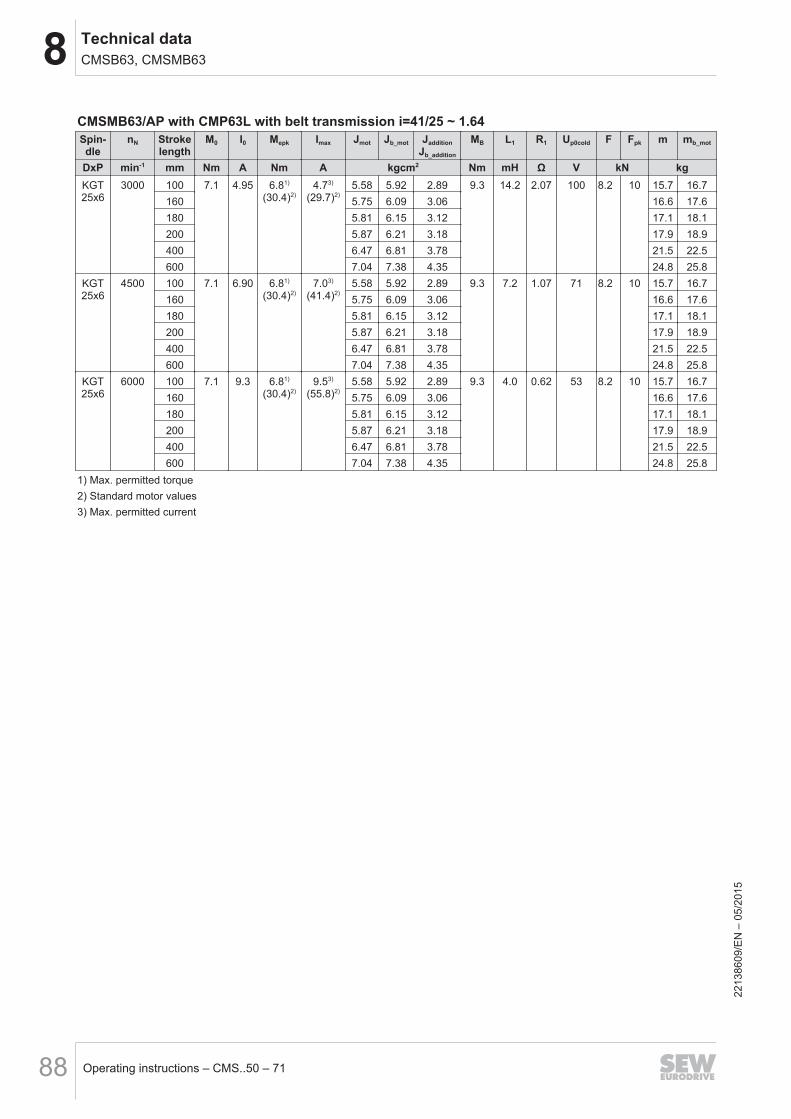
8 Technical dataCMSB63, CMSMB63
Operating instructions – CMS..50 – 7188
CMSMB63/AP with CMP63L with belt transmission i=41/25 ~ 1.64Spin-dle
nN Strokelength
M0 I0 Mepk Imax Jmot Jb_mot JadditionJb_addition
MB L1 R1 Up0cold F Fpk m mb_mot
DxP min-1 mm Nm A Nm A kgcm2 Nm mH Ω V kN kgKGT25x6
3000 100 7.1 4.95 6.81)
(30.4)2)4.73)
(29.7)2)5.58 5.92 2.89 9.3 14.2 2.07 100 8.2 10 15.7 16.7
160 5.75 6.09 3.06 16.6 17.6180 5.81 6.15 3.12 17.1 18.1200 5.87 6.21 3.18 17.9 18.9400 6.47 6.81 3.78 21.5 22.5600 7.04 7.38 4.35 24.8 25.8
KGT25x6
4500 100 7.1 6.90 6.81)
(30.4)2)7.03)
(41.4)2)5.58 5.92 2.89 9.3 7.2 1.07 71 8.2 10 15.7 16.7
160 5.75 6.09 3.06 16.6 17.6180 5.81 6.15 3.12 17.1 18.1200 5.87 6.21 3.18 17.9 18.9400 6.47 6.81 3.78 21.5 22.5600 7.04 7.38 4.35 24.8 25.8
KGT25x6
6000 100 7.1 9.3 6.81)
(30.4)2)9.53)
(55.8)2)5.58 5.92 2.89 9.3 4.0 0.62 53 8.2 10 15.7 16.7
160 5.75 6.09 3.06 16.6 17.6180 5.81 6.15 3.12 17.1 18.1200 5.87 6.21 3.18 17.9 18.9400 6.47 6.81 3.78 21.5 22.5600 7.04 7.38 4.35 24.8 25.8
1) Max. permitted torque2) Standard motor values3) Max. permitted current
2213
8609
/EN
– 0
5/20
15
8Technical dataCMSB71, CMSMB71
Operating instructions – CMS..50 – 71 89
8.6 CMSB71, CMSMB718.6.1 Features
The table below shows the features.
Design Standard Optional
Degree of protection IP65
Motor protection KTY
Mounting position M0
Cooling Natural convection/water cooling VR forced cooling fan
Lubrication Oil bath lubrication Food grade lubricant
Spindle protection Smooth piston rod with sealing system
8.6.2 Technical data
INFORMATIONStroke length 100, 160, 200, 400, 600, 800, 1000 und 1200 mm → npk =4500 min-1 (max. mechanical speed)
NOTICEAdhere to the maximum permitted torque Mpk or Mepk for electric cylinders of lengthM and L.
A current limitation is required on the frequency inverter.
2213
8609
/EN
– 0
5/20
15
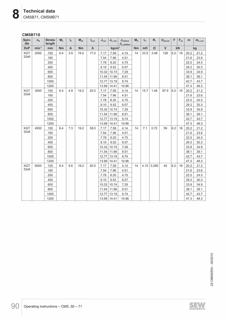
8 Technical dataCMSB71, CMSMB71
Operating instructions – CMS..50 – 7190
CMSB71SSpin-dle
nN Strokelength
M0 I0 Mpk Imax Jmot Jb_mot JadditionJb_addition
MB L1 R1 Up0cold F Fpk m mb_mot
DxP min-1 mm Nm A Nm A kgcm2 Nm mH Ω V kN kgKGT32x6
2000 100 6.4 3.9 19.2 17.0 7.17 7.59 4.14 14 33.5 3.48 128 6.2 18 20.2 21.2160 7.54 7.96 4.51 21.6 23.6200 7.78 8.20 4.75 22.5 24.5400 9.10 9.52 6.07 29.3 30.3600 10.32 10.74 7.29 33.9 34.9800 11.54 11.96 8.51 38.1 39.11000 12.77 13.19 9.74 42.7 43.71200 13.99 14.41 10.96 47.3 48.3
KGT32x6
3000 100 6.4 4.9 19.2 25.0 7.17 7.59 4.14 14 15.7 1.48 87.5 6.2 18 20.2 21.2160 7.54 7.96 4.51 21.6 23.6200 7.78 8.20 4.75 22.5 24.5400 9.10 9.52 6.07 29.3 30.3600 10.32 10.74 7.29 33.9 34.9800 11.54 11.96 8.51 38.1 39.11000 12.77 13.19 9.74 42.7 43.71200 13.99 14.41 10.96 47.3 48.3
KGT32x6
4500 100 6.4 7.3 19.2 38.0 7.17 7.59 4.14 14 7.1 0.72 59 6.2 18 20.2 21.2160 7.54 7.96 4.51 21.6 23.6200 7.78 8.20 4.75 22.5 24.5400 9.10 9.52 6.07 29.3 30.3600 10.32 10.74 7.29 33.9 34.9800 11.54 11.96 8.51 38.1 39.11000 12.77 13.19 9.74 42.7 43.71200 13.99 14.41 10.96 47.3 48.3
KGT32x6
6000 100 6.4 9.6 19.2 50.0 7.17 7.59 4.14 14 4.15 0,395 45 6.2 18 20.2 21.2160 7.54 7.96 4.51 21.6 23.6200 7.78 8.20 4.75 22.5 24.5400 9.10 9.52 6.07 29.3 30.3600 10.32 10.74 7.29 33.9 34.9800 11.54 11.96 8.51 38.1 39.11000 12.77 13.19 9.74 42.7 43.71200 13.99 14.41 10.96 47.3 48.3
2213
8609
/EN
– 0
5/20
15
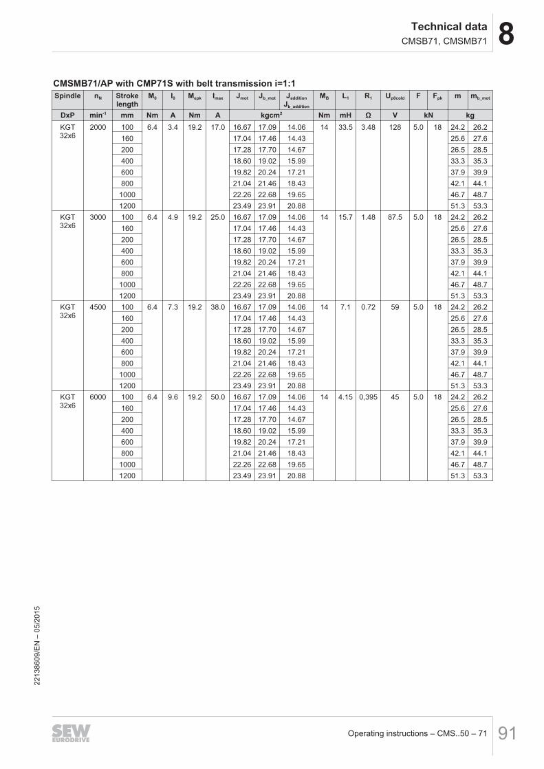
8Technical dataCMSB71, CMSMB71
Operating instructions – CMS..50 – 71 91
CMSMB71/AP with CMP71S with belt transmission i=1:1Spindle nN Stroke
lengthM0 I0 Mepk Imax Jmot Jb_mot Jaddition
Jb_addition
MB L1 R1 Up0cold F Fpk m mb_mot
DxP min-1 mm Nm A Nm A kgcm2 Nm mH Ω V kN kgKGT32x6
2000 100 6.4 3.4 19.2 17.0 16.67 17.09 14.06 14 33.5 3.48 128 5.0 18 24.2 26.2160 17.04 17.46 14.43 25.6 27.6200 17.28 17.70 14.67 26.5 28.5400 18.60 19.02 15.99 33.3 35.3600 19.82 20.24 17.21 37.9 39.9800 21.04 21.46 18.43 42.1 44.11000 22.26 22.68 19.65 46.7 48.71200 23.49 23.91 20.88 51.3 53.3
KGT32x6
3000 100 6.4 4.9 19.2 25.0 16.67 17.09 14.06 14 15.7 1.48 87.5 5.0 18 24.2 26.2160 17.04 17.46 14.43 25.6 27.6200 17.28 17.70 14.67 26.5 28.5400 18.60 19.02 15.99 33.3 35.3600 19.82 20.24 17.21 37.9 39.9800 21.04 21.46 18.43 42.1 44.11000 22.26 22.68 19.65 46.7 48.71200 23.49 23.91 20.88 51.3 53.3
KGT32x6
4500 100 6.4 7.3 19.2 38.0 16.67 17.09 14.06 14 7.1 0.72 59 5.0 18 24.2 26.2160 17.04 17.46 14.43 25.6 27.6200 17.28 17.70 14.67 26.5 28.5400 18.60 19.02 15.99 33.3 35.3600 19.82 20.24 17.21 37.9 39.9800 21.04 21.46 18.43 42.1 44.11000 22.26 22.68 19.65 46.7 48.71200 23.49 23.91 20.88 51.3 53.3
KGT32x6
6000 100 6.4 9.6 19.2 50.0 16.67 17.09 14.06 14 4.15 0,395 45 5.0 18 24.2 26.2160 17.04 17.46 14.43 25.6 27.6200 17.28 17.70 14.67 26.5 28.5400 18.60 19.02 15.99 33.3 35.3600 19.82 20.24 17.21 37.9 39.9800 21.04 21.46 18.43 42.1 44.11000 22.26 22.68 19.65 46.7 48.71200 23.49 23.91 20.88 51.3 53.3
2213
8609
/EN
– 0
5/20
15

8 Technical dataCMSB71, CMSMB71
Operating instructions – CMS..50 – 7192
CMSMB71/AP with CMP71S with belt transmission i=57/47 ~ 1.21Spin-dle
nN Strokelength
M0 I0 Mepk Imax Jmot Jb_mot JadditionJb_addition
MB L1 R1 Up0cold F Fpk m mb_mot
DxP min-1 mm Nm A Nm A kgcm2 Nm mH Ω V kN kgKGT32x6
2000 100 6.4 3.4 19.2 17.0 15.67 16.43 13.02 14 33.5 3.48 128 6.0 21.7 24.2 26.2160 16.02 16.79 13.36 25.6 27.6200 16.24 17.02 13.58 26.5 28.5400 17.48 18.29 14.81 33.3 35.3600 18.63 19.46 15.94 37.9 39.9800 19.77 20.63 17.06 42.1 44.11000 20.92 21.81 18.19 46.7 48.71200 22.08 22.99 19.33 51.3 53.3
KGT32x6
3000 100 6.4 4.9 19.2 25.0 15.67 16.43 13.02 14 15.7 1.48 87.5 6.0 21.7 24.2 26.2160 16.02 16.79 13.36 25.6 27.6200 16.24 17.02 13.58 26.5 28.5400 17.48 18.29 14.81 33.3 35.3600 18.63 19.46 15.94 37.9 39.9800 19.77 20.63 17.06 42.1 44.11000 20.92 21.81 18.19 46.7 48.71200 22.08 22.99 19.33 51.3 53.3
KGT32x6
4500 100 6.4 7.3 19.2 38.0 15.67 16.43 13.02 14 7.1 0.72 59 6.0 21.7 24.2 26.2160 16.02 16.79 13.36 25.6 27.6200 16.24 17.02 13.58 26.5 28.5400 17.48 18.29 14.81 33.3 35.3600 18.63 19.46 15.94 37.9 39.9800 19.77 20.63 17.06 42.1 44.11000 20.92 21.81 18.19 46.7 48.71200 22.08 22.99 19.33 51.3 53.3
KGT32x6
6000 100 6.4 9.6 19.2 50.0 15.67 16.43 13.02 14 4.15 0,395 45 6.0 21.7 24.2 26.2160 16.02 16.79 13.36 25.6 27.6200 16.24 17.02 13.58 26.5 28.5400 17.48 18.29 14.81 33.3 35.3600 18.63 19.46 15.94 37.9 39.9800 19.77 20.63 17.06 42.1 44.11000 20.92 21.81 18.19 46.7 48.71200 22.08 22.99 19.33 51.3 53.3
2213
8609
/EN
– 0
5/20
15
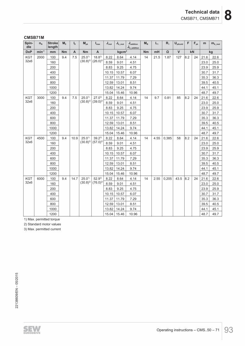
8Technical dataCMSB71, CMSMB71
Operating instructions – CMS..50 – 71 93
CMSB71MSpin-dle
nN Strokelength
M0 I0 Mpk Imax Jmot Jb_mot JadditionJb_addition
MB L1 R1 Up0cold F Fpk m mb_mot
DxP min-1 mm Nm A Nm A kgcm2 Nm mH Ω V kN kgKGT32x6
2000 100 9.4 7.5 25.01)
(30.8)2)18.83)
(26.0)2)8.22 8.64 4.14 14 21.5 1.87 127 8.2 24 21.6 22.6
160 8.59 9.01 4.51 23.0 25.0200 8.83 9.25 4.75 23.9 25.9400 10.15 10.57 6.07 30.7 31.7600 11.37 11.79 7.29 35.3 36.3800 12.59 13.01 8.51 39.5 40.51000 13.82 14.24 9.74 44.1 45.11200 15.04 15.46 10.96 48.7 49.7
KGT32x6
3000 100 9.4 7.5 25.01)
(30.8)2)27.03)
(39.0)2)8.22 8.64 4.14 14 9.7 0.81 85 8.2 24 21.6 22.6
160 8.59 9.01 4.51 23.0 25.0200 8.83 9.25 4.75 23.9 25.9400 10.15 10.57 6.07 30.7 31.7600 11.37 11.79 7.29 35.3 36.3800 12.59 13.01 8.51 39.5 40.51000 13.82 14.24 9.74 44.1 45.11200 15.04 15.46 10.96 48.7 49.7
KGT32x6
4500 100 9.4 10.9 25.01)
(30.8)2)39.23)
(57.0)2)8.22 8.64 4.14 14 4.55 0,385 58 8.2 24 21.6 22.6
160 8.59 9.01 4.51 23.0 25.0200 8.83 9.25 4.75 23.9 25.9400 10.15 10.57 6.07 30.7 31.7600 11.37 11.79 7.29 35.3 36.3800 12.59 13.01 8.51 39.5 40.51000 13.82 14.24 9.74 44.1 45.11200 15.04 15.46 10.96 48.7 49.7
KGT32x6
6000 100 9.4 14.7 25.01)
(30.8)2)52.93)
(76.0)2)8.22 8.64 4.14 14 2.55 0,205 43.5 8.2 24 21.6 22.6
160 8.59 9.01 4.51 23.0 25.0200 8.83 9.25 4.75 23.9 25.9400 10.15 10.57 6.07 30.7 31.7600 11.37 11.79 7.29 35.3 36.3800 12.59 13.01 8.51 39.5 40.51000 13.82 14.24 9.74 44.1 45.11200 15.04 15.46 10.96 48.7 49.7
1) Max. permitted torque2) Standard motor values3) Max. permitted current
2213
8609
/EN
– 0
5/20
15
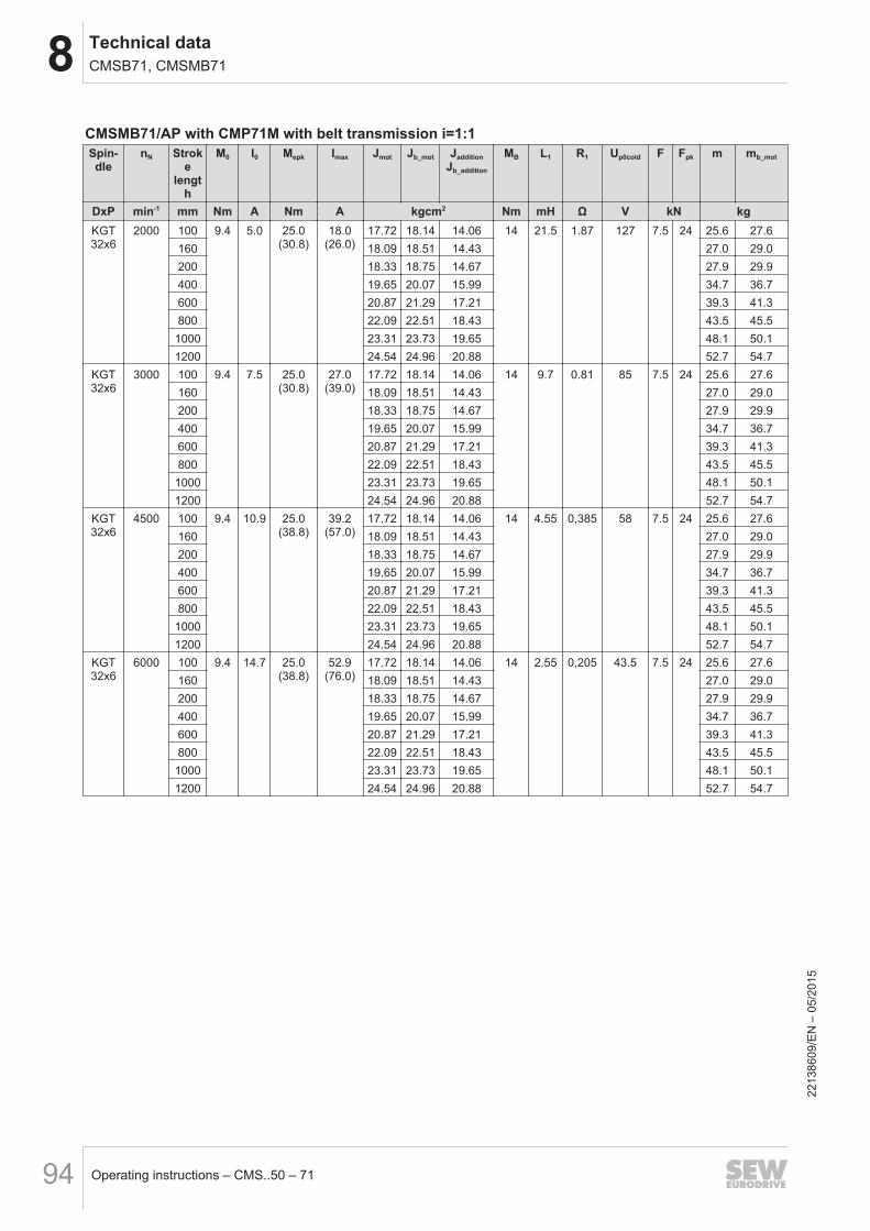
8 Technical dataCMSB71, CMSMB71
Operating instructions – CMS..50 – 7194
CMSMB71/AP with CMP71M with belt transmission i=1:1Spin-dle
nN Stroke
length
M0 I0 Mepk Imax Jmot Jb_mot JadditionJb_addition
MB L1 R1 Up0cold F Fpk m mb_mot
DxP min-1 mm Nm A Nm A kgcm2 Nm mH Ω V kN kgKGT32x6
2000 100 9.4 5.0 25.0(30.8)
18.0(26.0)
17.72 18.14 14.06 14 21.5 1.87 127 7.5 24 25.6 27.6160 18.09 18.51 14.43 27.0 29.0200 18.33 18.75 14.67 27.9 29.9400 19.65 20.07 15.99 34.7 36.7600 20.87 21.29 17.21 39.3 41.3800 22.09 22.51 18.43 43.5 45.51000 23.31 23.73 19.65 48.1 50.11200 24.54 24.96 20.88 52.7 54.7
KGT32x6
3000 100 9.4 7.5 25.0(30.8)
27.0(39.0)
17.72 18.14 14.06 14 9.7 0.81 85 7.5 24 25.6 27.6160 18.09 18.51 14.43 27.0 29.0200 18.33 18.75 14.67 27.9 29.9400 19.65 20.07 15.99 34.7 36.7600 20.87 21.29 17.21 39.3 41.3800 22.09 22.51 18.43 43.5 45.51000 23.31 23.73 19.65 48.1 50.11200 24.54 24.96 20.88 52.7 54.7
KGT32x6
4500 100 9.4 10.9 25.0(38.8)
39.2(57.0)
17.72 18.14 14.06 14 4.55 0,385 58 7.5 24 25.6 27.6160 18.09 18.51 14.43 27.0 29.0200 18.33 18.75 14.67 27.9 29.9400 19.65 20.07 15.99 34.7 36.7600 20.87 21.29 17.21 39.3 41.3800 22.09 22.51 18.43 43.5 45.5
1000 23.31 23.73 19.65 48.1 50.11200 24.54 24.96 20.88 52.7 54.7
KGT32x6
6000 100 9.4 14.7 25.0(38.8)
52.9(76.0)
17.72 18.14 14.06 14 2.55 0,205 43.5 7.5 24 25.6 27.6160 18.09 18.51 14.43 27.0 29.0200 18.33 18.75 14.67 27.9 29.9400 19.65 20.07 15.99 34.7 36.7600 20.87 21.29 17.21 39.3 41.3800 22.09 22.51 18.43 43.5 45.5
1000 23.31 23.73 19.65 48.1 50.11200 24.54 24.96 20.88 52.7 54.7
2213
8609
/EN
– 0
5/20
15

8Technical dataCMSB71, CMSMB71
Operating instructions – CMS..50 – 71 95
CMSMB71/AP with CMP71M with belt transmission i=57/47 ~ 1.21Spin-dle
nN Strokelength
M0 I0 Mepk Imax Jmot Jb_mot JadditionJb_addition
MB L1 R1 Up0cold F Fpk m mb_mot
DxP min-1 mm Nm A Nm A kgcm2 Nm mH Ω V kN kgKGT32x6
2000 100 9.4 5.0 20.71)
(30.8)2)12.03)
(26.0)2)16.65 17.07 12.99 14 21.5 1.87 127 9 24 25.6 27.6
160 17.06 17.48 13.40 27.0 29.0200 17.33 17.75 13.67 27.9 29.9400 18.77 19.19 15.11 34.7 36.7600 20.12 20.54 16.46 39.3 41.3800 21.46 21.88 17.80 43.5 45.51000 22.80 23.22 19.14 48.1 50.11200 24.15 24.57 20.49 52.7 54.7
KGT32x6
3000 100 9.4 7.5 20.71)
(30.8)2)
18.03)
(39.0)2)16.65 17.07 12.99 14 9.7 0.81 85 9 24 25.6 27.6
160 17.06 17.48 13.40 27.0 29.0200 17.33 17.75 13.67 27.9 29.9400 18.77 19.19 15.11 34.7 36.7600 20.12 20.54 16.46 39.3 41.3800 21.46 21.88 17.80 43.5 45.51000 22.80 23.22 19.14 48.1 50.11200 24.15 24.57 20.49 52.7 54.7
KGT32x6
4500 100 9.4 10.9 20.71)
(30.8)2)26.23)
(57.0)2)16.65 17.07 12.99 14 4.55 0,385 58 9 24 25.6 27.6
160 17.06 17.48 13.40 27.0 29.0200 17.33 17.75 13.67 27.9 29.9400 18.77 19.19 15.11 34.7 36.7600 20.12 20.54 16.46 39.3 41.3800 21.46 21.88 17.80 43.5 45.51000 22.80 23.22 19.14 48.1 50.11200 24.15 24.57 20.49 52.7 54.7
KGT32x6
6000 100 9.4 14.7 20.71)
(30.8)2)35.33)
(76.0)2)16.65 17.07 12.99 14 2.55 0,205 43.5 9 24 25.6 27.6
160 17.06 17.48 13.40 27.0 29.0200 17.33 17.75 13.67 27.9 29.9400 18.77 19.19 15.11 34.7 36.7600 20.12 20.54 16.46 39.3 41.3800 21.46 21.88 17.80 43.5 45.51000 22.80 23.22 19.14 48.1 50.11200 24.15 24.57 20.49 52.7 54.7
1) Max. permitted torque2) Standard motor values3) Max. permitted current
2213
8609
/EN
– 0
5/20
15
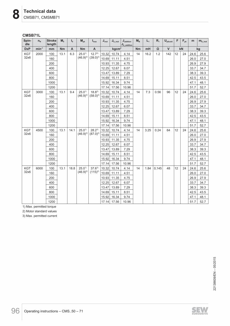
8 Technical dataCMSB71, CMSMB71
Operating instructions – CMS..50 – 7196
CMSB71LSpin-dle
nN Strokelength
M0 I0 Mpk Imax Jmot Jb_mot JadditionJb_addition
MB L1 R1 Up0cold F Fpk m mb_mot
DxP min-1 mm Nm A Nm A kgcm2 Nm mH Ω V kN kgKGT32x6
2000 100 13.1 6.3 25.01)
(46.9)2)12.73)
(39.0)2)10.32 10.74 4.14 14 16.2 1.2 142 12 24 24.6 25.6
160 10.69 11.11 4.51 26.0 27.0200 10.93 11.35 4.75 26.9 27.9400 12.25 12.67 6.07 33.7 34.7600 13.47 13.89 7.29 38.3 39.3800 14.69 15.11 8.51 42.5 43.51000 15.92 16.34 9.74 47.1 48.11200 17.14 17.56 10.96 51.7 52.7
KGT32x6
3000 100 13.1 9.4 25.01)
(46.9)2)18.83)
(58.0)2)10.32 10.74 4.14 14 7.3 0.56 96 12 24 24.6 25.6
160 10.69 11.11 4.51 26.0 27.0200 10.93 11.35 4.75 26.9 27.9400 12.25 12.67 6.07 33.7 34.7600 13.47 13.89 7.29 38.3 39.3800 14.69 15.11 8.51 42.5 43.51000 15.92 16.34 9.74 47.1 48.11200 17.14 17.56 10.96 51.7 52.7
KGT32x6
4500 100 13.1 14.1 25.01)
(46.9)2)28.23)
(87.0)2)10.32 10.74 4.14 14 3.25 0.24 64 12 24 24.6 25.6
160 10.69 11.11 4.51 26.0 27.0200 10.93 11.35 4.75 26.9 27.9400 12.25 12.67 6.07 33.7 34.7600 13.47 13.89 7.29 38.3 39.3800 14.69 15.11 8.51 42.5 43.51000 15.92 16.34 9.74 47.1 48.11200 17.14 17.56 10.96 51.7 52.7
KGT32x6
6000 100 13.1 18.8 25.01)
(46.9)2)37.63)
(115)2)10.32 10.74 4.14 14 1.84 0,145 48 12 24 24.6 25.6
160 10.69 11.11 4.51 26.0 27.0200 10.93 11.35 4.75 26.9 27.9400 12.25 12.67 6.07 33.7 34.7600 13.47 13.89 7.29 38.3 39.3800 14.69 15.11 8.51 42.5 43.5
1000 15.92 16.34 9.74 47.1 48.11200 17.14 17.56 10.96 51.7 52.7
1) Max. permitted torque2) Motor standard values3) Max. permitted current
2213
8609
/EN
– 0
5/20
15
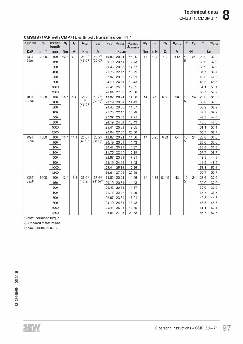
8Technical dataCMSB71, CMSMB71
Operating instructions – CMS..50 – 71 97
CMSMB71/AP with CMP71L with belt transmission i=1:1Spindle nN Stroke
lengthM0 I0 Mepk Imax Jmot Jb_mot Jaddition
Jb_addition
MB L1 R1 Up0cold F Fpk m mb_mot
DxP min-1 mm Nm A Nm A kgcm2 Nm mH Ω V kN kgKGT32x6
2000 100 13.1 6.3 25.01)
(46.9)2)12.73)
(39.0)2)19.82 20.24 14.06 14 16.2 1.2 142 10.
524 28.6 30.6
160 20.19 20.61 14.43 30.0 32.0200 20.43 20.85 14.67 30.9 32.9400 21.75 22.17 15.99 37.7 39.7600 22.97 23.39 17.21 42.3 44.3800 24.19 24.61 18.43 46.5 48.51000 25.41 25.83 19.65 51.1 53.11200 26.64 27.06 20.88 55.7 57.7
KGT32x6
3000 100 13.1 9.4 25.01)
(46.9)2)
18.83)
(58.0)2)19.82 20.24 14.06 14 7.3 0.56 96 10.
524 28.6 30.6
160 20.19 20.61 14.43 30.0 32.0200 20.43 20.85 14.67 30.9 32.9400 21.75 22.17 15.99 37.7 39.7600 22.97 23.39 17.21 42.3 44.3800 24.19 24.61 18.43 46.5 48.5
1000 25.41 25.83 19.65 51.1 53.11200 26.64 27.06 20.88 55.7 57.7
KGT32x6
4500 100 13.1 14.1 25.01)
(46.9)2)28.23)
(87.0)2)19.82 20.24 14.06 14 3.25 0.24 64 10.
524 28.6 30.6
160 20.19 20.61 14.43 30.0 32.0200 20.43 20.85 14.67 30.9 32.9400 21.75 22.17 15.99 37.7 39.7600 22.97 23.39 17.21 42.3 44.3800 24.19 24.61 18.43 46.5 48.5
1000 25.41 25.83 19.65 51.1 53.11200 26.64 27.06 20.88 55.7 57.7
KGT32x6
6000 100 13.1 18.8 25.01)
(46.9)2)37.63)
(115)2)19.82 20.24 14.06 14 1.84 0,145 48 10.
524 28.6 30.6
160 20.19 20.61 14.43 30.0 32.0200 20.43 20.85 14.67 30.9 32.9400 21.75 22.17 15.99 37.7 39.7600 22.97 23.39 17.21 42.3 44.3800 24.19 24.61 18.43 46.5 48.51000 25.41 25.83 19.65 51.1 53.11200 26.64 27.06 20.88 55.7 57.7
1) Max. permitted torque2) Standard motor values3) Max. permitted current
2213
8609
/EN
– 0
5/20
15
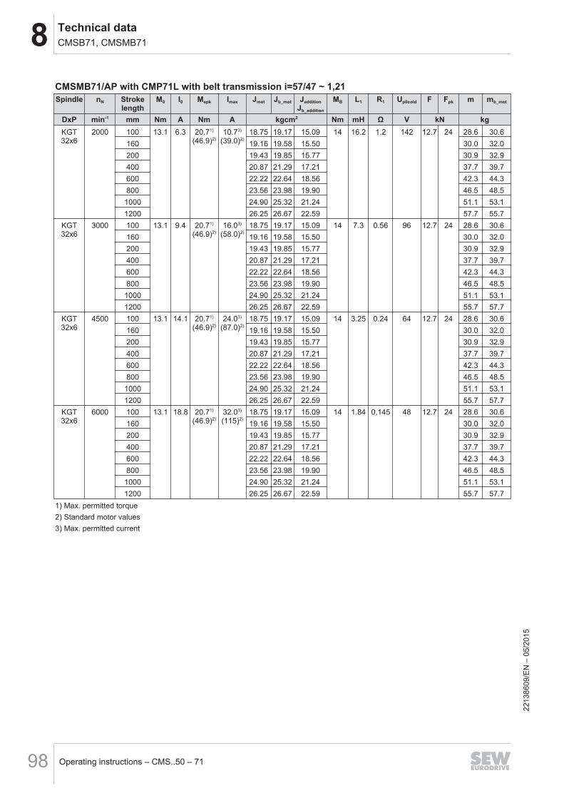
8 Technical dataCMSB71, CMSMB71
Operating instructions – CMS..50 – 7198
CMSMB71/AP with CMP71L with belt transmission i=57/47 ~ 1,21Spindle nN Stroke
lengthM0 I0 Mepk Imax Jmot Jb_mot Jaddition
Jb_addition
MB L1 R1 Up0cold F Fpk m mb_mot
DxP min-1 mm Nm A Nm A kgcm2 Nm mH Ω V kN kgKGT32x6
2000 100 13.1 6.3 20.71)
(46.9)2)10.73)
(39.0)2)18.75 19.17 15.09 14 16.2 1.2 142 12.7 24 28.6 30.6
160 19.16 19.58 15.50 30.0 32.0200 19.43 19.85 15.77 30.9 32.9400 20.87 21.29 17.21 37.7 39.7600 22.22 22.64 18.56 42.3 44.3800 23.56 23.98 19.90 46.5 48.51000 24.90 25.32 21.24 51.1 53.11200 26.25 26.67 22.59 57.7 55.7
KGT32x6
3000 100 13.1 9.4 20.71)
(46.9)2)16.03)
(58.0)2)18.75 19.17 15.09 14 7.3 0.56 96 12.7 24 28.6 30.6
160 19.16 19.58 15.50 30.0 32.0200 19.43 19.85 15.77 30.9 32.9400 20.87 21.29 17.21 37.7 39.7600 22.22 22.64 18.56 42.3 44.3800 23.56 23.98 19.90 46.5 48.51000 24.90 25.32 21.24 51.1 53.11200 26.25 26.67 22.59 55.7 57.7
KGT32x6
4500 100 13.1 14.1 20.71)
(46.9)2)24.03)
(87.0)2)18.75 19.17 15.09 14 3.25 0.24 64 12.7 24 28.6 30.6
160 19.16 19.58 15.50 30.0 32.0200 19.43 19.85 15.77 30.9 32.9400 20.87 21.29 17.21 37.7 39.7600 22.22 22.64 18.56 42.3 44.3800 23.56 23.98 19.90 46.5 48.51000 24.90 25.32 21.24 51.1 53.11200 26.25 26.67 22.59 55.7 57.7
KGT32x6
6000 100 13.1 18.8 20.71)
(46.9)2)32.03)
(115)2)18.75 19.17 15.09 14 1.84 0,145 48 12.7 24 28.6 30.6
160 19.16 19.58 15.50 30.0 32.0200 19.43 19.85 15.77 30.9 32.9400 20.87 21.29 17.21 37.7 39.7600 22.22 22.64 18.56 42.3 44.3800 23.56 23.98 19.90 46.5 48.5
1000 24.90 25.32 21.24 51.1 53.11200 26.25 26.67 22.59 55.7 57.7
1) Max. permitted torque2) Standard motor values3) Max. permitted current
2213
8609
/EN
– 0
5/20
15
8Technical dataCMS71L
Operating instructions – CMS..50 – 71 99
8.7 CMS71L8.7.1 Features
Design Standard Optional
Degree of protection IP45 (IP65)1)
Motor protection TF KTY/TH
Mounting position any
Cooling Natural convection
Lubrication Fixed lubrication point with taper greasingnipple DIN 71412-A
Lubricator, chapter 7.6
Spindle protection Bellows1) For electrical components
2213
8609
/EN
– 0
5/20
15
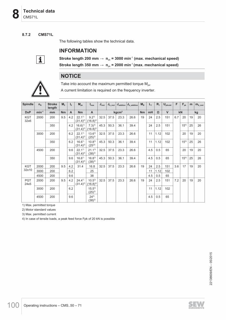
8 Technical dataCMS71L
Operating instructions – CMS..50 – 71100
8.7.2 CMS71LThe following tables show the technical data.
INFORMATIONStroke length 200 mm → nek = 3000 min-1 (max. mechanical speed)Stroke length 350 mm → npk = 2000 min-1 (max. mechanical speed)
NOTICETake into account the maximum permitted torque Mpk.
A current limitation is required on the frequency inverter.
Spindle nN Strokelength
M0 I0 Mpk Imax Jmot Jb_mot Jaddition Jb_addition MB L1 R1 Up0cold F Fpk m mb_mot
DxP min-1 mm Nm A Nm A kgcm2 Nm mH Ω V kN kgKGT32x6
2000 200 9.5 4.2 22.11)
(31.4)2)9.23)
(16.8)2)32.5 37.5 23.3 26.6 19 24 2.5 151 6.7 20 19 20
350 4.2 16.6)1)
(31.4)2)7.3)3)
(16.8)2)45.3 50.3 36.1 39.4 24 2.5 151 154) 25 26
3000 200 6.2 22.11)
(31.4)2)13.63)
(25)2)32.5 37.5 23.3 26.6 11 1.12 102 20 19 20
350 6.2 16.61)
(31.4)2)10.83)
(25)2)45.3 50.3 36.1 39.4 11 1.12 102 154) 25 26
4500 200 9.6 22.11)
(31.4)2)21.13)
(38)2)32.5 37.5 23.3 26.6 4.5 0.5 65 20 19 20
350 9.6 16.61)
(31.4)2)16.83)
(38)2)45.3 50.3 36.1 39.4 4.5 0.5 65 154) 25 26
KGT32x10
2000 200 9.5 4.2 31.4 16.8 32.5 37.5 23.3 26.6 19 24 2.5 151 3.6 17 19 203000 200 6.2 25 11 1.12 1024500 200 9.6 38 4.5 0.5 65
PGT24x5
2000 200 9.5 4.2 24.41)
(31.4)2)10.53)
(16.8)4)32.5 37.5 23.3 26.6 19 24 2.5 151 7.2 20 19 20
3000 200 6.2 15.53)
(25)2)11 1.12 102
4500 200 9.6 243)
(38)2)4.5 0.5 65
1) Max. permitted torque2) Motor standard values3) Max. permitted current4) In case of tensile loads, a peak feed force Fpk of 20 kN is possible
2213
8609
/EN
– 0
5/20
15
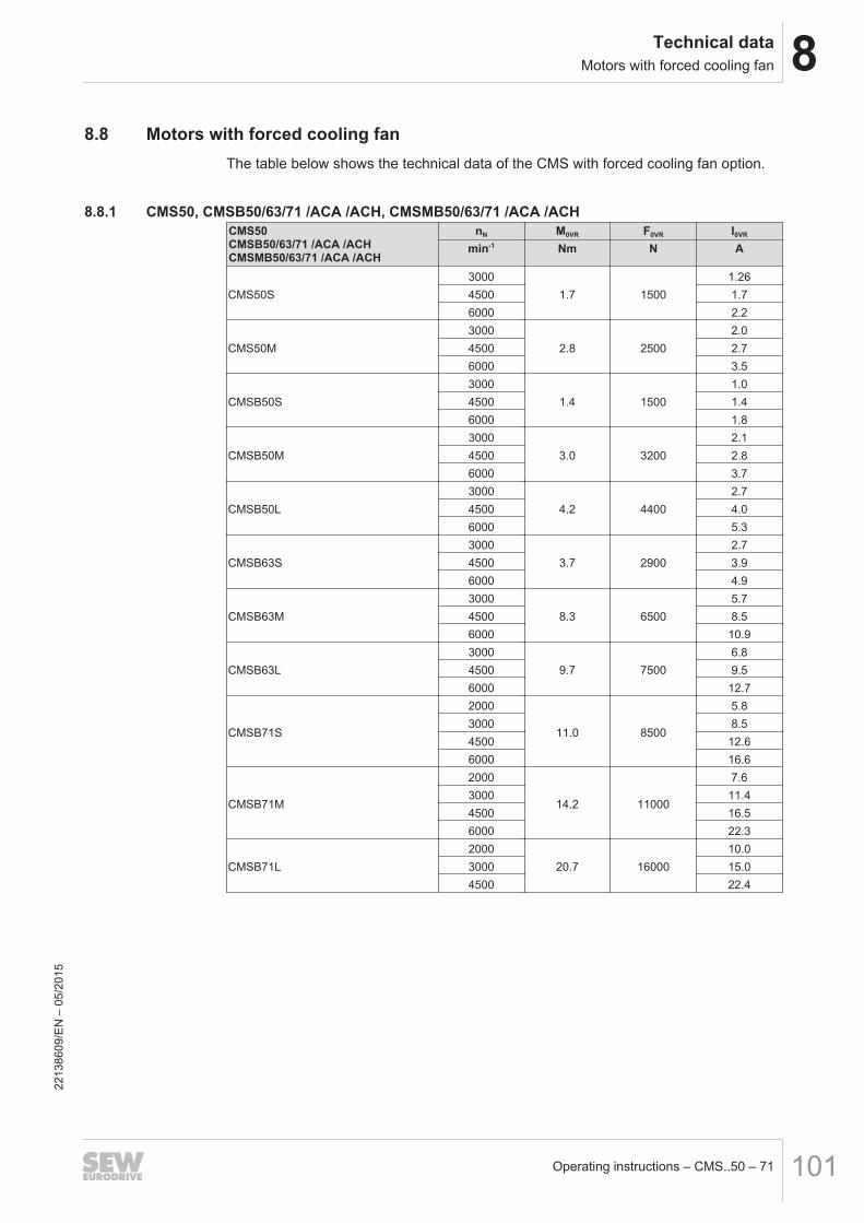
8Technical dataMotors with forced cooling fan
Operating instructions – CMS..50 – 71 101
8.8 Motors with forced cooling fanThe table below shows the technical data of the CMS with forced cooling fan option.
8.8.1 CMS50, CMSB50/63/71 /ACA /ACH, CMSMB50/63/71 /ACA /ACHCMS50CMSB50/63/71 /ACA /ACHCMSMB50/63/71 /ACA /ACH
nN M0VR F0VR I0VR
min-1 Nm N A
CMS50S3000
1.7 15001.26
4500 1.76000 2.2
CMS50M3000
2.8 25002.0
4500 2.76000 3.5
CMSB50S3000
1.4 15001.0
4500 1.46000 1.8
CMSB50M3000
3.0 32002.1
4500 2.86000 3.7
CMSB50L3000
4.2 44002.7
4500 4.06000 5.3
CMSB63S3000
3.7 29002.7
4500 3.96000 4.9
CMSB63M3000
8.3 65005.7
4500 8.56000 10.9
CMSB63L3000
9.7 75006.8
4500 9.56000 12.7
CMSB71S
2000
11.0 8500
5.83000 8.54500 12.66000 16.6
CMSB71M
2000
14.2 11000
7.63000 11.44500 16.56000 22.3
CMSB71L2000
20.7 1600010.0
3000 15.04500 22.4
2213
8609
/EN
– 0
5/20
15
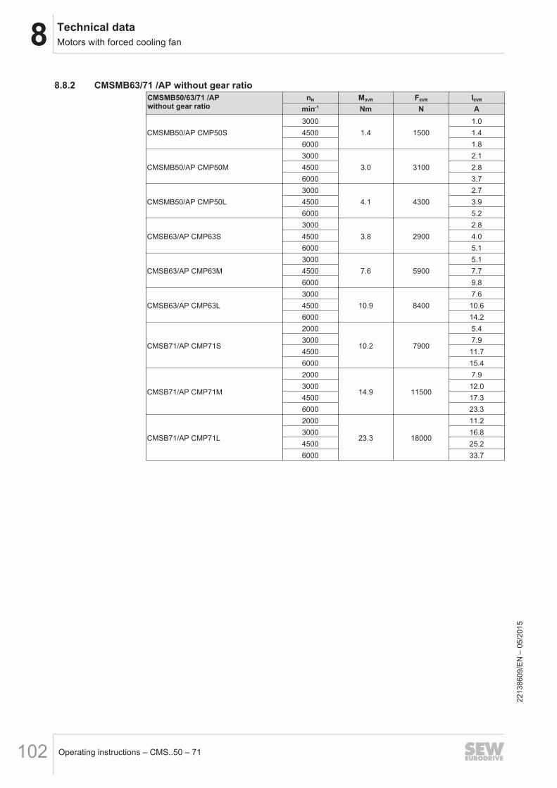
8 Technical dataMotors with forced cooling fan
Operating instructions – CMS..50 – 71102
8.8.2 CMSMB63/71 /AP without gear ratioCMSMB50/63/71 /AP without gear ratio
nN M0VR F0VR I0VR
min-1 Nm N A
CMSMB50/AP CMP50S3000
1.4 15001.0
4500 1.46000 1.8
CMSMB50/AP CMP50M3000
3.0 31002.1
4500 2.86000 3.7
CMSMB50/AP CMP50L3000
4.1 43002.7
4500 3.96000 5.2
CMSB63/AP CMP63S3000
3.8 29002.8
4500 4.06000 5.1
CMSB63/AP CMP63M3000
7.6 59005.1
4500 7.76000 9.8
CMSB63/AP CMP63L3000
10.9 84007.6
4500 10.66000 14.2
CMSB71/AP CMP71S
2000
10.2 7900
5.43000 7.94500 11.76000 15.4
CMSB71/AP CMP71M
2000
14.9 11500
7.93000 12.04500 17.36000 23.3
CMSB71/AP CMP71L
2000
23.3 18000
11.23000 16.84500 25.26000 33.7
2213
8609
/EN
– 0
5/20
15
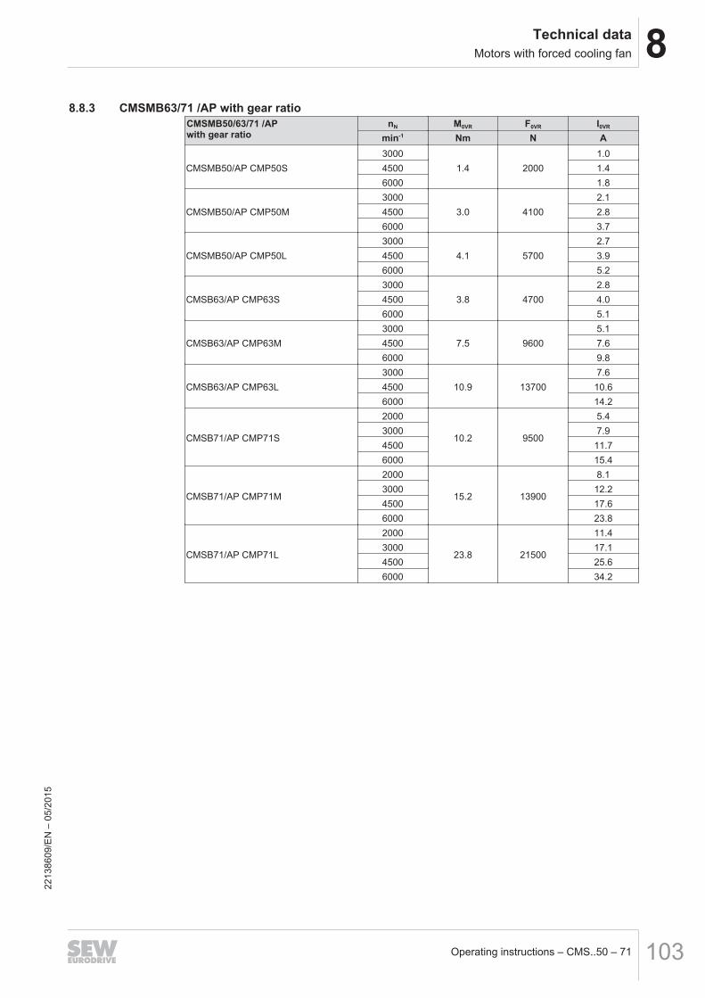
8Technical dataMotors with forced cooling fan
Operating instructions – CMS..50 – 71 103
8.8.3 CMSMB63/71 /AP with gear ratioCMSMB50/63/71 /AP with gear ratio
nN M0VR F0VR I0VR
min-1 Nm N A
CMSMB50/AP CMP50S3000
1.4 20001.0
4500 1.46000 1.8
CMSMB50/AP CMP50M3000
3.0 41002.1
4500 2.86000 3.7
CMSMB50/AP CMP50L3000
4.1 57002.7
4500 3.96000 5.2
CMSB63/AP CMP63S3000
3.8 47002.8
4500 4.06000 5.1
CMSB63/AP CMP63M3000
7.5 96005.1
4500 7.66000 9.8
CMSB63/AP CMP63L3000
10.9 137007.6
4500 10.66000 14.2
CMSB71/AP CMP71S
2000
10.2 9500
5.43000 7.94500 11.76000 15.4
CMSB71/AP CMP71M
2000
15.2 13900
8.13000 12.24500 17.66000 23.8
CMSB71/AP CMP71L
2000
23.8 21500
11.43000 17.14500 25.66000 34.2
2213
8609
/EN
– 0
5/20
15
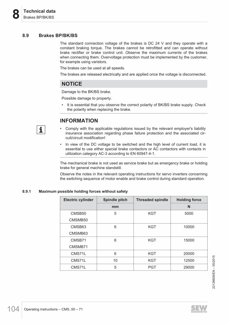
8 Technical dataBrakes BP/BK/BS
Operating instructions – CMS..50 – 71104
8.9 Brakes BP/BK/BSThe standard connection voltage of the brakes is DC 24 V and they operate with aconstant braking torque. The brakes cannot be retrofitted and can operate withoutbrake rectifier or brake control unit. Observe the maximum currents of the brakeswhen connecting them. Overvoltage protection must be implemented by the customer,for example using varistors.The brakes can be used at all speeds.The brakes are released electrically and are applied once the voltage is disconnected.
NOTICEDamage to the BK/BS brake.
Possible damage to property.
• It is essential that you observe the correct polarity of BK/BS brake supply. Checkthe polarity when replacing the brake.
INFORMATION• Comply with the applicable regulations issued by the relevant employer's liability
insurance association regarding phase failure protection and the associated cir-cuit/circuit modification!
• In view of the DC voltage to be switched and the high level of current load, it isessential to use either special brake contactors or AC contactors with contacts inutilization category AC-3 according to EN 60947-4-1.
The mechanical brake is not used as service brake but as emergency brake or holdingbrake for general machine standstill.Observe the notes in the relevant operating instructions for servo inverters concerningthe switching sequence of motor enable and brake control during standard operation.
8.9.1 Maximum possible holding forces without safety
Electric cylinder Spindle pitch Threaded spindle Holding force
mm N
CMSB50
CMSMB50
5 KGT 5000
CMSB63
CMSMB63
6 KGT 10000
CMSB71
CMSMB71
6 KGT 15000
CMS71L 6 KGT 20000
CMS71L 10 KGT 12500
CMS71L 5 PGT 29000
2213
8609
/EN
– 0
5/20
15
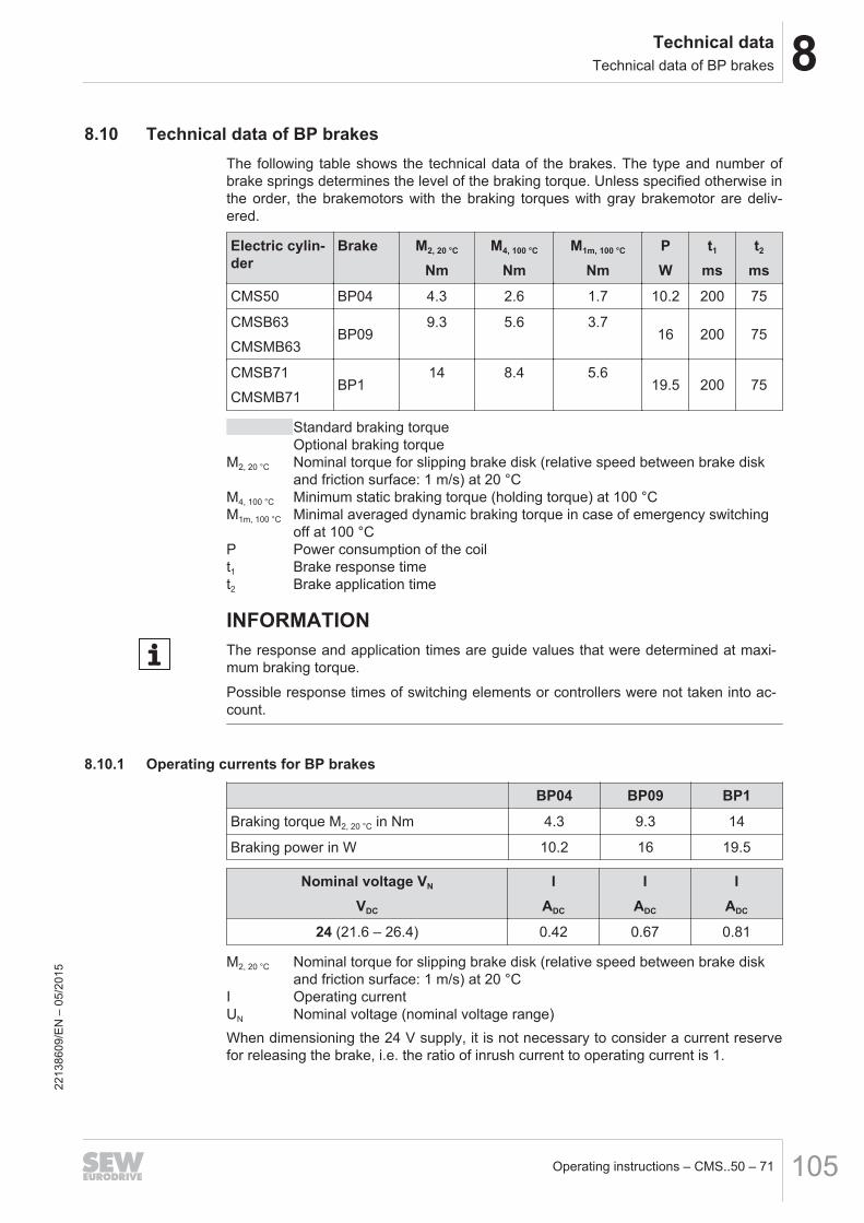
8Technical dataTechnical data of BP brakes
Operating instructions – CMS..50 – 71 105
8.10 Technical data of BP brakesThe following table shows the technical data of the brakes. The type and number ofbrake springs determines the level of the braking torque. Unless specified otherwise inthe order, the brakemotors with the braking torques with gray brakemotor are deliv-ered.
Electric cylin-der
Brake M2, 20 °C
NmM4, 100 °C
NmM1m, 100 °C
NmPW
t1
mst2
ms
CMS50 BP04 4.3 2.6 1.7 10.2 200 75
CMSB63
CMSMB63BP09
9.3 5.6 3.716 200 75
CMSB71
CMSMB71BP1
14 8.4 5.619.5 200 75
Standard braking torqueOptional braking torque
M2, 20 °C Nominal torque for slipping brake disk (relative speed between brake diskand friction surface: 1 m/s) at 20 °C
M4, 100 °C Minimum static braking torque (holding torque) at 100 °CM1m, 100 °C Minimal averaged dynamic braking torque in case of emergency switching
off at 100 °CP Power consumption of the coilt1 Brake response timet2 Brake application time
INFORMATIONThe response and application times are guide values that were determined at maxi-mum braking torque.
Possible response times of switching elements or controllers were not taken into ac-count.
8.10.1 Operating currents for BP brakes
BP04 BP09 BP1
Braking torque M2, 20 °C in Nm 4.3 9.3 14
Braking power in W 10.2 16 19.5
Nominal voltage VN
VDC
IADC
IADC
IADC
24 (21.6 – 26.4) 0.42 0.67 0.81
M2, 20 °C Nominal torque for slipping brake disk (relative speed between brake diskand friction surface: 1 m/s) at 20 °C
I Operating currentUN Nominal voltage (nominal voltage range)When dimensioning the 24 V supply, it is not necessary to consider a current reservefor releasing the brake, i.e. the ratio of inrush current to operating current is 1.
2213
8609
/EN
– 0
5/20
15
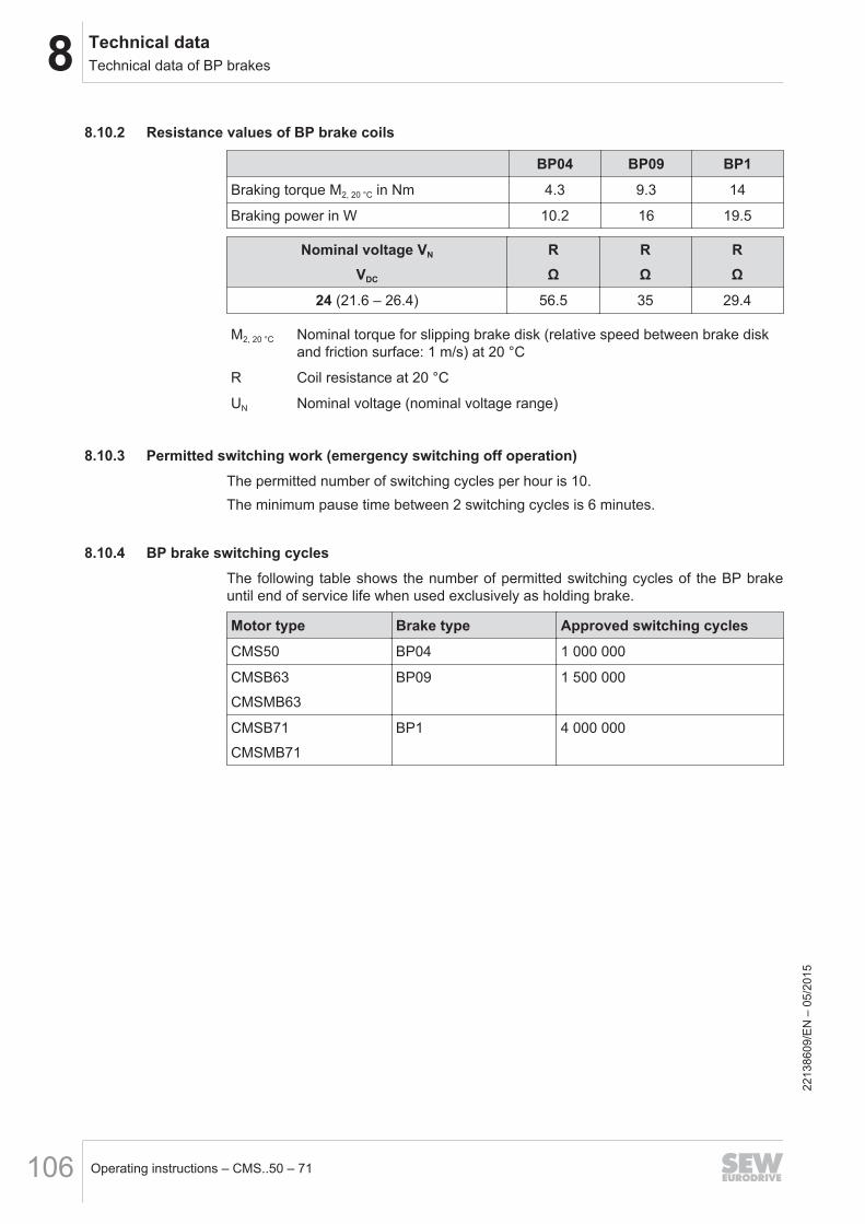
8 Technical dataTechnical data of BP brakes
Operating instructions – CMS..50 – 71106
8.10.2 Resistance values of BP brake coils
BP04 BP09 BP1
Braking torque M2, 20 °C in Nm 4.3 9.3 14
Braking power in W 10.2 16 19.5
Nominal voltage VN
VDC
RΩ
RΩ
RΩ
24 (21.6 – 26.4) 56.5 35 29.4
M2, 20 °C Nominal torque for slipping brake disk (relative speed between brake diskand friction surface: 1 m/s) at 20 °C
R Coil resistance at 20 °C
UN Nominal voltage (nominal voltage range)
8.10.3 Permitted switching work (emergency switching off operation)The permitted number of switching cycles per hour is 10.The minimum pause time between 2 switching cycles is 6 minutes.
8.10.4 BP brake switching cyclesThe following table shows the number of permitted switching cycles of the BP brakeuntil end of service life when used exclusively as holding brake.
Motor type Brake type Approved switching cycles
CMS50 BP04 1 000 000
CMSB63
CMSMB63
BP09 1 500 000
CMSB71
CMSMB71
BP1 4 000 000
2213
8609
/EN
– 0
5/20
15
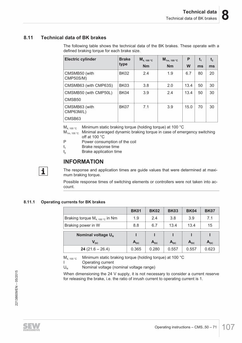
8Technical dataTechnical data of BK brakes
Operating instructions – CMS..50 – 71 107
8.11 Technical data of BK brakesThe following table shows the technical data of the BK brakes. These operate with adefined braking torque for each brake size.
Electric cylinder Braketype
M4, 100 °C
NmM1m, 100 °C
NmPW
t1
mst2
ms
CMSMB50 (withCMP50S/M)
BK02 2.4 1.9 6.7 80 20
CMSMB63 (with CMP63S) BK03 3.8 2.0 13.4 50 30
CMSMB50 (with CMP50L)
CMSB50
BK04 3.9 2.4 13.4 50 30
CMSMB63 (withCMP63M/L)
CMSB63
BK07 7.1 3.9 15.0 70 30
M4, 100 °C Minimum static braking torque (holding torque) at 100 °CM1m, 100 °C Minimal averaged dynamic braking torque in case of emergency switching
off at 100 °CP Power consumption of the coilt1 Brake response timet2 Brake application time
INFORMATIONThe response and application times are guide values that were determined at maxi-mum braking torque.
Possible response times of switching elements or controllers were not taken into ac-count.
8.11.1 Operating currents for BK brakes
BK01 BK02 BK03 BK04 BK07
Braking torque M4, 100 °C in Nm 1.9 2.4 3.8 3.9 7.1
Braking power in W 8.8 6.7 13.4 13.4 15
Nominal voltage UN
VDC
IADC
IADC
IADC
IADC
IADC
24 (21.6 – 26.4) 0.365 0.280 0.557 0.557 0.623
M4, 100 °C Minimum static braking torque (holding torque) at 100 °CI Operating currentUN Nominal voltage (nominal voltage range)When dimensioning the 24 V supply, it is not necessary to consider a current reservefor releasing the brake, i.e. the ratio of inrush current to operating current is 1.
2213
8609
/EN
– 0
5/20
15
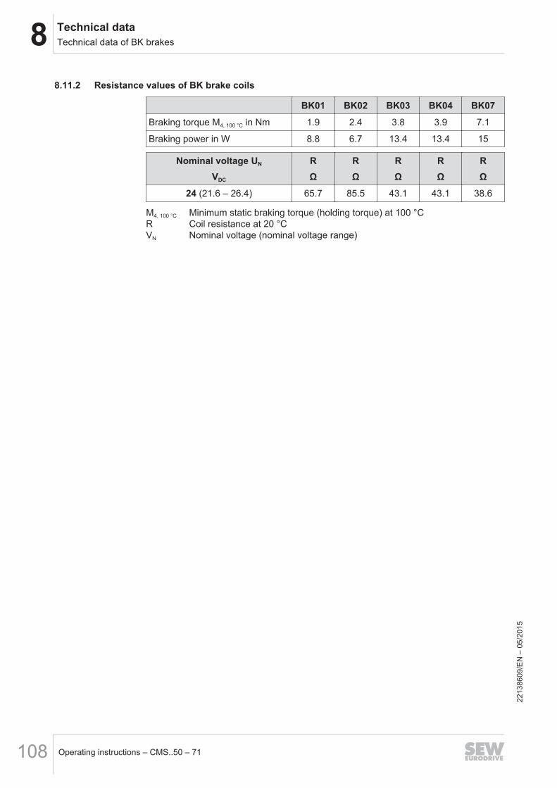
8 Technical dataTechnical data of BK brakes
Operating instructions – CMS..50 – 71108
8.11.2 Resistance values of BK brake coils
BK01 BK02 BK03 BK04 BK07
Braking torque M4, 100 °C in Nm 1.9 2.4 3.8 3.9 7.1
Braking power in W 8.8 6.7 13.4 13.4 15
Nominal voltage UN
VDC
RΩ
RΩ
RΩ
RΩ
RΩ
24 (21.6 – 26.4) 65.7 85.5 43.1 43.1 38.6
M4, 100 °C Minimum static braking torque (holding torque) at 100 °CR Coil resistance at 20 °CVN Nominal voltage (nominal voltage range)
2213
8609
/EN
– 0
5/20
15
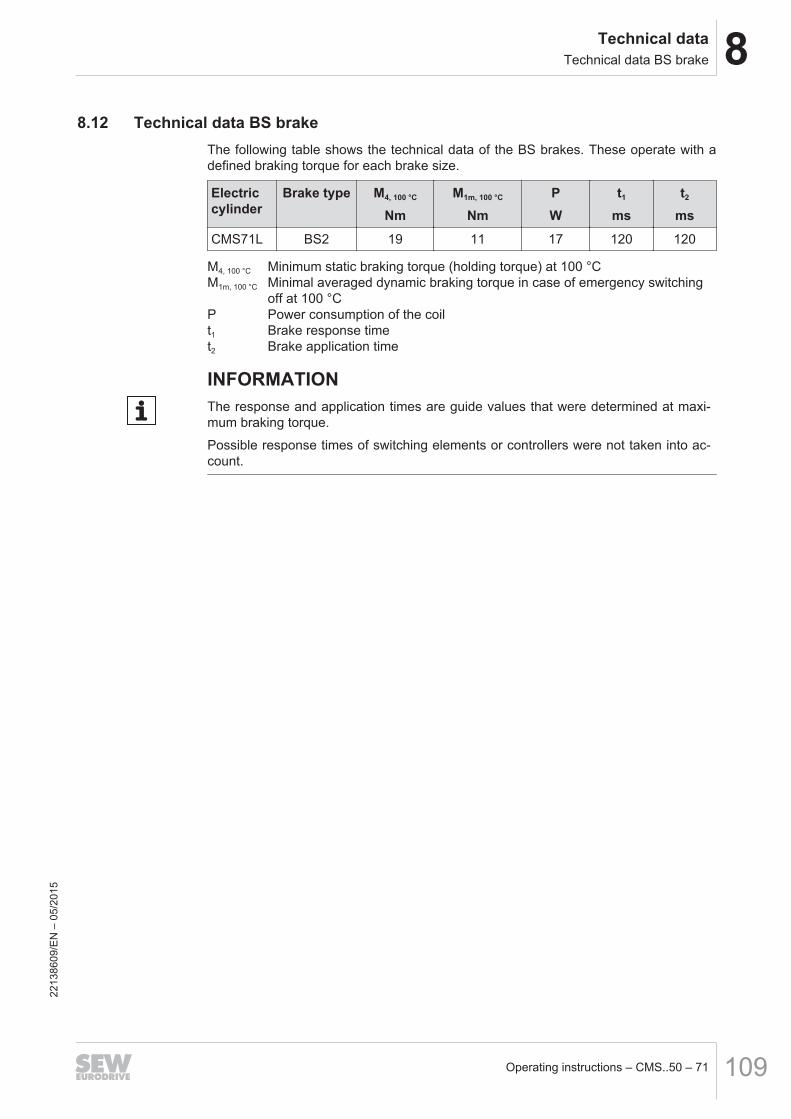
8Technical dataTechnical data BS brake
Operating instructions – CMS..50 – 71 109
8.12 Technical data BS brakeThe following table shows the technical data of the BS brakes. These operate with adefined braking torque for each brake size.
Electriccylinder
Brake type M4, 100 °C
NmM1m, 100 °C
NmPW
t1
mst2
ms
CMS71L BS2 19 11 17 120 120
M4, 100 °C Minimum static braking torque (holding torque) at 100 °CM1m, 100 °C Minimal averaged dynamic braking torque in case of emergency switching
off at 100 °CP Power consumption of the coilt1 Brake response timet2 Brake application time
INFORMATIONThe response and application times are guide values that were determined at maxi-mum braking torque.
Possible response times of switching elements or controllers were not taken into ac-count.
2213
8609
/EN
– 0
5/20
15
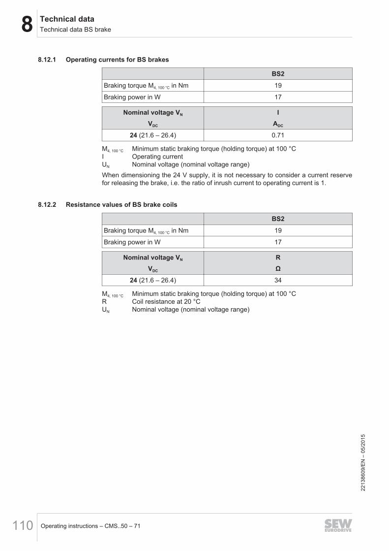
8 Technical dataTechnical data BS brake
Operating instructions – CMS..50 – 71110
8.12.1 Operating currents for BS brakes
BS2
Braking torque M4, 100 °C in Nm 19
Braking power in W 17
Nominal voltage VN
VDC
IADC
24 (21.6 – 26.4) 0.71
M4, 100 °C Minimum static braking torque (holding torque) at 100 °CI Operating currentUN Nominal voltage (nominal voltage range)When dimensioning the 24 V supply, it is not necessary to consider a current reservefor releasing the brake, i.e. the ratio of inrush current to operating current is 1.
8.12.2 Resistance values of BS brake coils
BS2
Braking torque M4, 100 °C in Nm 19
Braking power in W 17
Nominal voltage VN
VDC
RΩ
24 (21.6 – 26.4) 34
M4, 100 °C Minimum static braking torque (holding torque) at 100 °CR Coil resistance at 20 °CUN Nominal voltage (nominal voltage range)
2213
8609
/EN
– 0
5/20
15
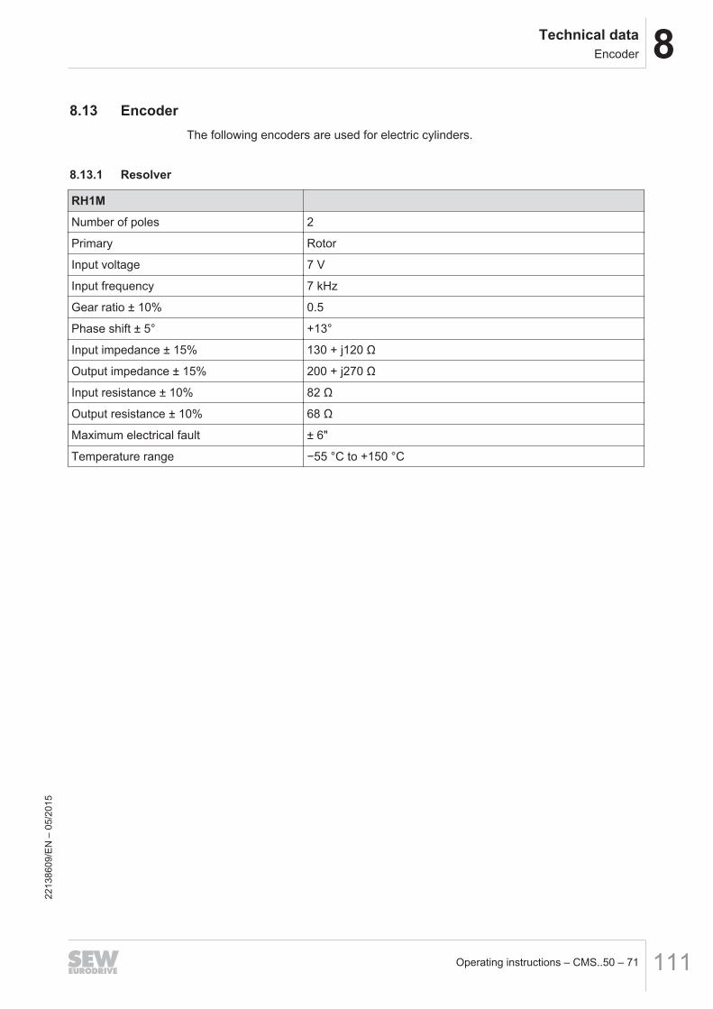
8Technical dataEncoder
Operating instructions – CMS..50 – 71 111
8.13 EncoderThe following encoders are used for electric cylinders.
8.13.1 Resolver
RH1M
Number of poles 2
Primary Rotor
Input voltage 7 V
Input frequency 7 kHz
Gear ratio ± 10% 0.5
Phase shift ± 5° +13°
Input impedance ± 15% 130 + j120 Ω
Output impedance ± 15% 200 + j270 Ω
Input resistance ± 10% 82 Ω
Output resistance ± 10% 68 Ω
Maximum electrical fault ± 6"
Temperature range −55 °C to +150 °C
2213
8609
/EN
– 0
5/20
15

8 Technical dataEncoder
Operating instructions – CMS..50 – 71112
8.13.2 Hiperface® encoder
/ES1H, /AS1H, /AK0H, /EK1H, /AK1H
SEW‑EURODRIVE offers Hiperface® encoders as an alternative to the resolver.
Type ES1H AS1H AK0H EK1H AK1H
CMS50/71CMSB63
CMS50/71CMSB63
CMS50/71CMSMB50/63/71
CMSB50/71CMSB631)
CMS711)
CMSB50/71CMSB631)
CMS711)
Supply voltage DC 7 - 8 - 12 V polarity reversal protected
Max. current con-sumption
140 mA 120 mA 140 mA
Maximum operatingfrequency
200 kHz 26 kHz 200 kHz
Pulses (sine cycles)per revolution
1024 128 1024
Output amplitude pertrack
0.9 - 1.1 VSS sin / cos 0.8 -1.1 VSS sin /cos
0.9 - 1.1 VSS sin/cos
Single-turn resolution 32768 increments/revolution(15 bits)
4096 increments/revolution (15
bits)
32768 increments/revolution (15bits)
Multi-turn resolution – 4096 revolutions (12 bits) – 4096 revolu-tions (12 bits)
Transmission proto-col
Hiperface®
Serial data output Driver to EIA RS-485
Vibration resistance(10-2000 Hz)
≤ 200 m/s2 (DIN IEC 68-2-6) ≤ 100 m/s2
(DIN IEC 68-2-6)
≤ 200 m/s2 (DIN IEC 68-2-6)
Maximum speed 12 000 min-1 9000 min-1 12 000 min-1
Connection 12-pin circulator connector
Temperature range -20 °C to +110 °C1) in preparation
2213
8609
/EN
– 0
5/20
15
9MalfunctionsNotes
Operating instructions – CMS..50 – 71 113
9 Malfunctions9.1 Notes
WARNINGRisk of crushing if the drive starts up unintentionally.
Severe or fatal injuries.
• De-energize the electric cylinder before you start working on the unit.
• Safeguard the electric cylinder against unintentional restart.
WARNINGIn lifting applications, note that the load torque of the application to be held in placemust be less than the holding torque of the brake used.
Severe or fatal injuries.
• Observe the project planning guidelines.
• The spindles that are used are not self-locking.
CAUTIONThe electric cylinder can get very hot during operation.
Risk of burns.
• Never touch the electric cylinder during operation or in the cool down phase onceit has been switched off.
NOTICEImproper troubleshooting may result in damages to the electric cylinder.
Possible damage to property.
• Note the following information.
• Components may be subject to mechanical loads. Support and secure the custom-er structure before removing the electric cylinder.
• Use only genuine spare parts in accordance with the valid spare parts list.• Strictly observe the safety notes in the individual chapters.
2213
8609
/EN
– 0
5/20
15
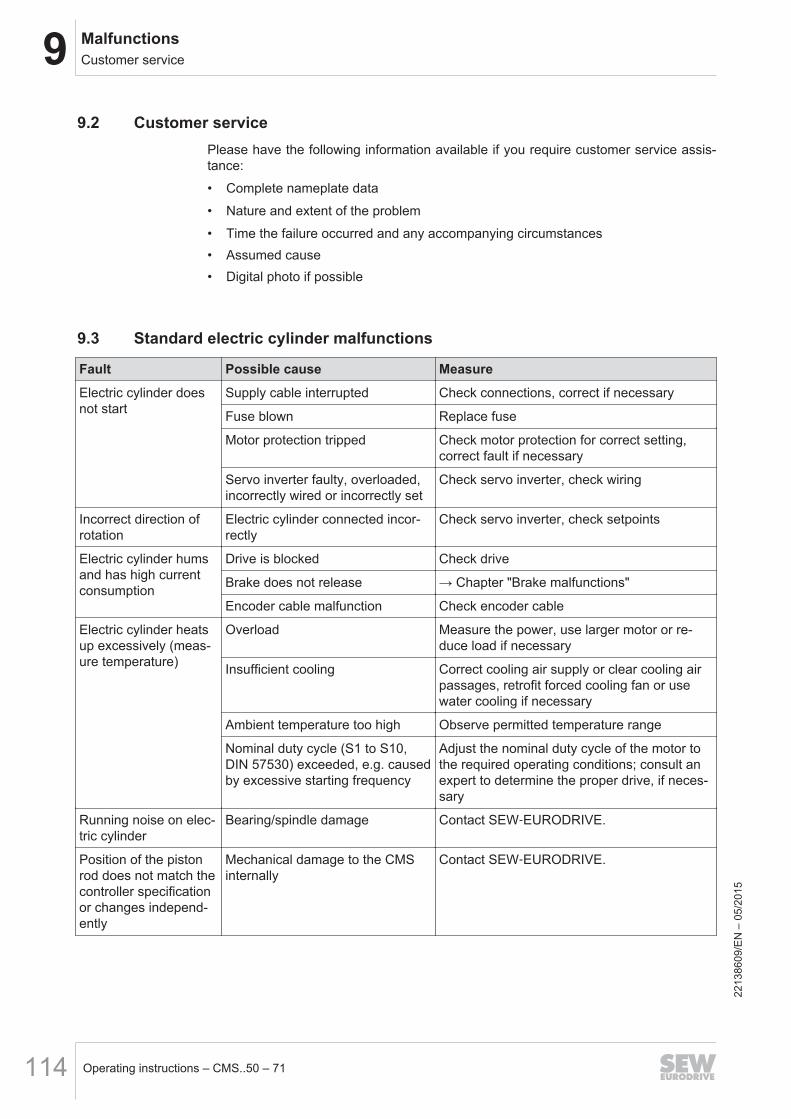
9 MalfunctionsCustomer service
Operating instructions – CMS..50 – 71114
9.2 Customer servicePlease have the following information available if you require customer service assis-tance:
• Complete nameplate data
• Nature and extent of the problem
• Time the failure occurred and any accompanying circumstances• Assumed cause• Digital photo if possible
9.3 Standard electric cylinder malfunctions
Fault Possible cause Measure
Electric cylinder doesnot start
Supply cable interrupted Check connections, correct if necessary
Fuse blown Replace fuse
Motor protection tripped Check motor protection for correct setting,correct fault if necessary
Servo inverter faulty, overloaded,incorrectly wired or incorrectly set
Check servo inverter, check wiring
Incorrect direction ofrotation
Electric cylinder connected incor-rectly
Check servo inverter, check setpoints
Electric cylinder humsand has high currentconsumption
Drive is blocked Check drive
Brake does not release → Chapter "Brake malfunctions"
Encoder cable malfunction Check encoder cable
Electric cylinder heatsup excessively (meas-ure temperature)
Overload Measure the power, use larger motor or re-duce load if necessary
Insufficient cooling Correct cooling air supply or clear cooling airpassages, retrofit forced cooling fan or usewater cooling if necessary
Ambient temperature too high Observe permitted temperature range
Nominal duty cycle (S1 to S10,DIN 57530) exceeded, e.g. causedby excessive starting frequency
Adjust the nominal duty cycle of the motor tothe required operating conditions; consult anexpert to determine the proper drive, if neces-sary
Running noise on elec-tric cylinder
Bearing/spindle damage Contact SEW‑EURODRIVE.
Position of the pistonrod does not match thecontroller specificationor changes independ-ently
Mechanical damage to the CMSinternally
Contact SEW‑EURODRIVE.
2213
8609
/EN
– 0
5/20
15

9MalfunctionsInverter malfunctions
Operating instructions – CMS..50 – 71 115
9.4 Inverter malfunctions
INFORMATIONOperating the electric cylinder with an inverter may also cause the described mal-functions (→ 2 113). Please refer to the inverter operating instructions for the mean-ing of the problems that occur and to find information about rectifying the problems.
Please have the following information to hand if you require the assistance ofour customer service:• Complete nameplate data
• Nature and extent of the problem
• Time the failure occurred and any accompanying circumstances• Assumed cause• Digital photo if possible
9.5 Brake malfunctions
Fault Possible cause Measure
Brake does not re-lease
Incorrect operating voltage on thebrake
Apply correct voltage.
Reversed polarity, only for BS2 brake.
Max. permitted working air gap ex-ceeded because brake lining worndown
Contact SEW‑EURODRIVE.
Voltage drop along supply cable >10%
Ensure correct connection voltage; check ca-ble cross section.
Brake coil has interturn short circuitor a short circuit to frame
Contact SEW‑EURODRIVE.
Motor does notbrake
Brake lining worn Contact SEW‑EURODRIVE.
Incorrect braking torque
Brake worn Brake release times incorrect Adjust brake release times to startup and de-celeration processes.
9.6 DisposalThis product consists of:• Iron
• Aluminum
• Copper• Plastics• Electronic componentsDispose of all components in accordance with applicable regulations.
2213
8609
/EN
– 0
5/20
15
Index
IndexB
Bellows ventilation................................................ 63BK brake
BK brake coil resistance ....................... 108, 110Operating currents ................................ 107, 110Technical data............................................... 107
BP brakeBrake coil resistance..................................... 106Operating currents ........................................ 105Technical data............................................... 105
Brake control, protection against interference...... 36Brake rectifier
BMV ................................................................ 44BS ................................................................... 44Direct voltage supply 24 V .............................. 45
BS brakeTechnical data............................................... 109
C
Connecting motor and encoder systemDependence of mating connector on cable di-ameter and crimping area ............................... 40Encoder cables ............................................... 40Forced cooling fan cables ............................... 40Plug connector on the cable end .................... 38Power cable and plug connector for CMP.. mo-tors .................................................................. 39Prefabricated cables ....................................... 41Replaced brakemotor cables .......................... 39
Connecting the motor and encoder system toKK/KKS terminal box ...................................... 46CMSMB71....................................................... 48
Connecting the motor and encoder system via aKK/KKS terminal boxCMP50 and CMP63 ........................................ 47
Connecting the motor and the encoder system viaplug connector SM. / SB. ................................ 38
Connection of signal plug connectors - encoder .. 43Connection of SM1/SB1 power plug connector -BP
brake ............................................................... 41Connection option via terminal box ...................... 46Connector positions
SM1/SB1, SMB/SBB....................................... 36Copyright notice ..................................................... 7
E
Electrical installation............................................. 35Embedded safety notes ......................................... 6Encoder cables .................................................... 40Exclusion of liability ................................................ 7
F
Filter ventilation .................................................... 63Forced cooling fan cables .................................... 40
G
General safety notes .............................................. 8
H
Hazard symbolsMeaning ............................................................ 6
I
Installation CMS50 and CMS63........................... 22Installation outdoors ............................................. 21
K
KTY temperature sensor ...................................... 51
L
Liquid cooling ................................................. 64, 65Lubricant .............................................................. 58Lubricating threaded spindles .............................. 56Lubricator ............................................................. 61
M
Motor protection ................................................... 36Mounting position ........................................... 19, 26Mounting tolerances for CMS71L......................... 32
N
NotesDesignation in the documentation..................... 5Meaning of the hazard symbols ........................ 6
O
Operating currentsBP brake ....................................................... 105
P
Pictograms on the motor ...................................... 12
2213
8609
/EN
– 0
5/15
Operating instructions – CMS..50 – 71116
Index
Plug connector on the cable end.......................... 38Power cable for CMP.. motors ............................. 39Prefabricated cables ............................................ 41Protecting the brake control system against interfer-
ence ................................................................ 36
R
ResistancesBP brake coil ................................................. 106
Rights to claim under limited warranty ................... 7
S
Safety notesDesignation in the documentation..................... 5General ............................................................. 8Meaning of the hazard symbols ........................ 6Operation ........................................................ 11Structure of embedded ..................................... 6Structure of the section-related......................... 6
Sealing air ............................................................ 62Section-related safety notes................................... 6Serial number....................................................... 16Signal words in the safety notes ............................ 5SM1/SB1, SMB/SBB
Connector positions ........................................ 36Stickers on the motor ........................................... 12Stroke limiting....................................................... 33Symbols on the motor .......................................... 12
T
Technical dataBK brake ....................................................... 107BP brake ....................................................... 105BS brake ....................................................... 109
Terminal box, connection variant ......................... 46TF temperature sensor......................................... 52Thermal motor protection ............................... 36, 51
Temperature sensor KTY84 – 130.................. 51TF temperature sensor ................................... 52
Tolerances for mounting CMS50S, CMSB50/63/71,CMSMB50/63/71at the customer site. ............ 31
Tolerances of the installation tolerances by the cus-tomer for CMS71L........................................... 32
Tools .................................................................... 20Type designation.................................................. 16
Connection variants ........................................ 18Encoder........................................................... 18
Mechanical mount-on components ................. 17Motor series .................................................... 17Temperature sensor and temperature detection........................................................................ 17Ventilation ....................................................... 18
Type designation of the plug connectors ............. 38
V
VR forced cooling fan..................................... 34, 52Electrical connection ....................................... 52Mechanical installation.................................... 34Retrofit set for CMP50 – CMP100 .................. 34
W
Warning notes on the motor................................. 12Wiring diagram for RH1M resolver signal plug con-
nectors ............................................................ 42Wiring diagrams of plug connectors..................... 41Wiring diagrams of the BP brake control – Terminal
boxBMV – CMSMB50/63...................................... 50BS – CMSMB50/63......................................... 50
Wiring diagrams of the BP/BK/BS brake control –Terminal box ................................................... 44
Wiring diagrams of the brake control – BP/BK brake– plug connector ............................................. 50
Wiring notes; NotesWiring.............................................................. 36
2213
8609
/EN
– 0
5/15
Operating instructions – CMS..50 – 71 117
10 Address list
Operating instructions – CMS..50 – 71118
10 Address listAlgeriaSales Algiers REDUCOM Sarl
16, rue des Frères ZaghnouneBellevue16200 El Harrach Alger
Tel. +213 21 8214-91Fax +213 21 8222-84http://[email protected]
ArgentinaAssemblySales
Buenos Aires SEW EURODRIVE ARGENTINA S.A.Ruta Panamericana Km 37.5, Lote 35(B1619IEA) Centro Industrial GarínProv. de Buenos Aires
Tel. +54 3327 4572-84Fax +54 3327 4572-21http://[email protected]
AustraliaAssemblySalesService
Melbourne SEW-EURODRIVE PTY. LTD.27 Beverage DriveTullamarine, Victoria 3043
Tel. +61 3 9933-1000Fax +61 3 9933-1003http://[email protected]
Sydney SEW-EURODRIVE PTY. LTD.9, Sleigh Place, Wetherill ParkNew South Wales, 2164
Tel. +61 2 9725-9900Fax +61 2 [email protected]
AustriaAssemblySalesService
Vienna SEW-EURODRIVE Ges.m.b.H.Richard-Strauss-Strasse 24A-1230 Wien
Tel. +43 1 617 55 00-0Fax +43 1 617 55 00-30http://[email protected]
Croatia Zagreb KOMPEKS d. o. o.Zeleni dol 10HR 10 000 Zagreb
Tel. +385 1 4613-158Fax +385 1 [email protected]
Romania Bucharest Sialco Trading SRLstr. Brazilia nr. 36011783 Bucuresti
Tel. +40 21 230-1328Fax +40 21 [email protected]
Serbia Belgrade DIPAR d.o.o.Ustanicka 128aPC Košum, IV floorSRB-11000 Beograd
Tel. +381 11 347 3244 /+381 11 288 0393Fax +381 11 347 [email protected]
Slovenia Celje Pakman - Pogonska Tehnika d.o.o.UI. XIV. divizije 14SLO - 3000 Celje
Tel. +386 3 490 83-20Fax +386 3 490 [email protected]
BangladeshSales Bangladesh SEW-EURODRIVE INDIA PRIVATE LIMITED
345 DIT RoadEast RampuraDhaka-1219, Bangladesh
Tel. +88 01729 [email protected]
BelarusSales Minsk Foreign Enterprise Industrial Components
RybalkoStr. 26BY-220033 Minsk
Tel. +375 17 298 47 56 / 298 47 58Fax +375 17 298 47 54http://[email protected]
BelgiumAssemblySalesService
Brussels SEW-EURODRIVE n.v./s.a.Researchpark Haasrode 1060Evenementenlaan 7BE-3001 Leuven
Tel. +32 16 386-311Fax +32 16 386-336http://[email protected]
Service CompetenceCenter
IndustrialGears
SEW-EURODRIVE n.v./s.a.Rue de Parc Industriel, 31BE-6900 Marche-en-Famenne
Tel. +32 84 219-878Fax +32 84 219-879http://[email protected]
2213
8609
/EN
– 0
5/20
15
10Address list
Operating instructions – CMS..50 – 71 119
BrazilProductionSalesService
São Paulo SEW-EURODRIVE Brasil Ltda.Estrada Municipal José Rubim, 205 – RodoviaSantos Dumont Km 49Indaiatuba – 13347-510 – SP
Tel. +55 19 [email protected]
AssemblySalesService
Rio Claro SEW-EURODRIVE Brasil Ltda.Rodovia Washington Luiz, Km 172Condomínio Industrial ConparkCaixa Postal: 32713501-600 – Rio Claro / SP
Tel. +55 19 3522-3100Fax +55 19 [email protected]
Joinville SEW-EURODRIVE Brasil Ltda.Rua Dona Francisca, 12.346 – Pirabeiraba89239-270 – Joinville / SC
Tel. +55 47 3027-6886Fax +55 47 [email protected]
BulgariaSales Sofia BEVER-DRIVE GmbH
Bogdanovetz Str.1BG-1606 Sofia
Tel. +359 2 9151160Fax +359 2 [email protected]
Cameroonis supported by Germany.
CanadaAssemblySalesService
Toronto SEW-EURODRIVE CO. OF CANADA LTD.210 Walker DriveBramalea, ON L6T 3W1
Tel. +1 905 791-1553Fax +1 905 791-2999http://[email protected]
Vancouver SEW-EURODRIVE CO. OF CANADA LTD.Tilbury Industrial Park7188 Honeyman StreetDelta, BC V4G 1G1
Tel. +1 604 946-5535Fax +1 604 [email protected]
Montreal SEW-EURODRIVE CO. OF CANADA LTD.2555 Rue LegerLasalle, PQ H8N 2V9
Tel. +1 514 367-1124Fax +1 514 [email protected]
ChileAssemblySalesService
Santiago deChile
SEW-EURODRIVE CHILE LTDALas Encinas 1295Parque Industrial Valle GrandeLAMPARCH-Santiago de ChileP.O. BoxCasilla 23 Correo Quilicura - Santiago - Chile
Tel. +56 2 2757 7000Fax +56 2 2757 7001http://[email protected]
ChinaProductionAssemblySalesService
Tianjin SEW-EURODRIVE (Tianjin) Co., Ltd.No. 78, 13th Avenue, TEDATianjin 300457
Tel. +86 22 25322612Fax +86 22 25323273http://[email protected]
AssemblySalesService
Suzhou SEW-EURODRIVE (Suzhou) Co., Ltd.333, Suhong Middle RoadSuzhou Industrial ParkJiangsu Province, 215021
Tel. +86 512 62581781Fax +86 512 [email protected]
Guangzhou SEW-EURODRIVE (Guangzhou) Co., Ltd.No. 9, JunDa RoadEast Section of GETDDGuangzhou 510530
Tel. +86 20 82267890Fax +86 20 [email protected]
Shenyang SEW-EURODRIVE (Shenyang) Co., Ltd.10A-2, 6th RoadShenyang Economic Technological Develop-ment AreaShenyang, 110141
Tel. +86 24 25382538Fax +86 24 [email protected]
Taiyuan SEW-EURODRIVE (Taiyuan) Co,. Ltd.No.3, HuaZhang Street,TaiYuan Economic & Technical DevelopmentZoneShanXi, 030032
Tel. +86-351-7117520Fax [email protected]
2213
8609
/EN
– 0
5/20
15
10 Address list
Operating instructions – CMS..50 – 71120
ChinaWuhan SEW-EURODRIVE (Wuhan) Co., Ltd.
10A-2, 6th RoadNo. 59, the 4th Quanli Road, WEDA430056 Wuhan
Tel. +86 27 84478388Fax +86 27 [email protected]
Xi'An SEW-EURODRIVE (Xi'An) Co., Ltd.No. 12 Jinye 2nd RoadXi'An High-Technology Industrial DevelopmentZoneXi'An 710065
Tel. +86 29 68686262Fax +86 29 [email protected]
SalesService
Hong Kong SEW-EURODRIVE LTD.Unit No. 801-806, 8th FloorHong Leong Industrial ComplexNo. 4, Wang Kwong RoadKowloon, Hong Kong
Tel. +852 36902200Fax +852 [email protected]
ColombiaAssemblySalesService
Bogota SEW-EURODRIVE COLOMBIA LTDA.Calle 22 No. 132-60Bodega 6, Manzana BSantafé de Bogotá
Tel. +57 1 54750-50Fax +57 1 54750-44http://[email protected]
CroatiaSalesService
Zagreb KOMPEKS d. o. o.Zeleni dol 10HR 10 000 Zagreb
Tel. +385 1 4613-158Fax +385 1 [email protected]
Czech RepublicAssemblySalesService
Hostivice SEW-EURODRIVE CZ s.r.o.Floriánova 2459253 01 Hostivice
Tel. +420 255 709 601Fax +420 235 350 613http://[email protected]
Drive ServiceHotline / 24Hour Service
+420 800 739 739 (800 SEW SEW) ServiceTel. +420 255 709 632Fax +420 235 358 [email protected]
DenmarkAssemblySalesService
Copenhagen SEW-EURODRIVEA/SGeminivej 28-30DK-2670 Greve
Tel. +45 43 95 8500Fax +45 43 9585-09http://[email protected]
EgyptSalesService
Cairo Copam Egyptfor Engineering & Agencies33 EI Hegaz STHeliopolis, Cairo
Tel. +20 222566299Fax +20 2 22594-757http://[email protected]
EstoniaSales Tallin ALAS-KUUL AS
Reti tee 4EE-75301 Peetri küla, Rae vald, Harjumaa
Tel. +372 6593230Fax +372 6593231http://[email protected]
FinlandAssemblySalesService
Hollola SEW-EURODRIVE OYVesimäentie 4FIN-15860 Hollola 2
Tel. +358 201 589-300Fax +358 3 780-6211http://[email protected]
Service Hollola SEW-EURODRIVE OYKeskikankaantie 21FIN-15860 Hollola
Tel. +358 201 589-300Fax +358 3 780-6211http://[email protected]
ProductionAssembly
Karkkila SEW Industrial Gears OySantasalonkatu 6, PL 8FI-03620 Karkkila, 03601 Karkkila
Tel. +358 201 589-300Fax +358 201 589-310http://[email protected] 22
1386
09/E
N –
05/
2015
10Address list
Operating instructions – CMS..50 – 71 121
FranceProductionSalesService
Hagenau SEW-USOCOME48-54 route de SoufflenheimB. P. 20185F-67506 Haguenau Cedex
Tel. +33 3 88 73 67 00Fax +33 3 88 73 66 00http://[email protected]
Production Forbach SEW-USOCOMEZone industrielleTechnopôle Forbach SudB. P. 30269F-57604 Forbach Cedex
Tel. +33 3 87 29 38 00
Brumath SEW-USOCOME1 rue de BruxellesF-67670 Mommenheim
Tel. +33 3 88 37 48 48
AssemblySalesService
Bordeaux SEW-USOCOMEParc d'activités de Magellan62 avenue de Magellan – B. P. 182F-33607 Pessac Cedex
Tel. +33 5 57 26 39 00Fax +33 5 57 26 39 09
Lyon SEW-USOCOMEParc d'affaires RooseveltRue Jacques TatiF-69120 Vaulx en Velin
Tel. +33 4 72 15 37 00Fax +33 4 72 15 37 15
Nantes SEW-USOCOMEParc d’activités de la forêt4 rue des FontenellesF-44140 Le Bignon
Tel. +33 2 40 78 42 00Fax +33 2 40 78 42 20
Paris SEW-USOCOMEZone industrielle2 rue Denis PapinF-77390 Verneuil I'Étang
Tel. +33 1 64 42 40 80Fax +33 1 64 42 40 88
Gabonis supported by Germany.
GermanyHeadquartersProductionSales
Bruchsal SEW-EURODRIVE GmbH & Co KGErnst-Blickle-Straße 42D-76646 BruchsalP.O. BoxPostfach 3023 – D-76642 Bruchsal
Tel. +49 7251 75-0Fax +49 7251 75-1970http://[email protected]
Production / IndustrialGears
Bruchsal SEW-EURODRIVE GmbH & Co KGChristian-Pähr-Str. 10D-76646 Bruchsal
Tel.. +49 7251 75-0Fax +49 7251 75-2970
Production Graben SEW-EURODRIVE GmbH & Co KGErnst-Blickle-Straße 1D-76676 Graben-NeudorfP.O. BoxPostfach 1220 – D-76671 Graben-Neudorf
Tel. +49 7251 75-0Fax +49 7251-2970
Östringen SEW-EURODRIVE GmbH & Co KG, WerkÖstringenFranz-Gurk-Straße 2D-76684 Östringen
Tel. +49 7253 9254-0Fax +49 7253 [email protected]
Service CompetenceCenter
Mechanics /Mechatronics
SEW-EURODRIVE GmbH & Co KGErnst-Blickle-Straße 1D-76676 Graben-Neudorf
Tel. +49 7251 75-1710Fax +49 7251 [email protected]
Electronics SEW-EURODRIVE GmbH & Co KGErnst-Blickle-Straße 42D-76646 Bruchsal
Tel. +49 7251 75-1780Fax +49 7251 [email protected]
Drive TechnologyCenter
North SEW-EURODRIVE GmbH & Co KGAlte Ricklinger Straße 40-42D-30823 Garbsen (Hannover)
Tel. +49 5137 8798-30Fax +49 5137 [email protected]
East SEW-EURODRIVE GmbH & Co KGDänkritzer Weg 1D-08393 Meerane (Zwickau)
Tel. +49 3764 7606-0Fax +49 3764 [email protected]
South SEW-EURODRIVE GmbH & Co KGDomagkstraße 5D-85551 Kirchheim (München)
Tel. +49 89 909552-10Fax +49 89 [email protected]
2213
8609
/EN
– 0
5/20
15
10 Address list
Operating instructions – CMS..50 – 71122
GermanyWest SEW-EURODRIVE GmbH & Co KG
Siemensstraße 1D-40764 Langenfeld (Düsseldorf)
Tel. +49 2173 8507-30Fax +49 2173 [email protected]
Drive Center Berlin SEW-EURODRIVE GmbH & Co KGAlexander-Meißner-Straße 44D-12526 Berlin
Tel. +49 306331131-30Fax +49 [email protected]
Ludwigshafen SEW-EURODRIVE GmbH & Co KGc/o BASF SEGebäude W130 Raum 101D-67056 Ludwigshafen
Tel. +49 7251 75 3759Fax +49 7251 75 [email protected]
Saarland SEW-EURODRIVE GmbH & Co KGGottlieb-Daimler-Straße 4D-66773 Schwalbach Saar – Hülzweiler
Tel. +49 6831 48946 10Fax +49 6831 48946 [email protected]
Ulm SEW-EURODRIVE GmbH & Co KGDieselstraße 18D-89160 Dornstadt
Tel. +49 7348 9885-0Fax +49 7348 [email protected]
Würzburg SEW-EURODRIVE GmbH & Co KGNürnbergerstraße 118D-97076 Würzburg-Lengfeld
Tel. +49 931 27886-60Fax +49 931 [email protected]
Drive Service Hotline / 24 Hour Service +49 800 SEWHELP+49 800 7394357
Great BritainAssemblySalesService
Normanton SEW-EURODRIVE Ltd.DeVilliers WayTrident ParkNormantonWest YorkshireWF6 1GX
Tel. +44 1924 893-855Fax +44 1924 893-702http://[email protected]
Drive Service Hotline / 24 Hour Service Tel. 01924 896911
GreeceSales Athens Christ. Boznos & Son S.A.
12, K. Mavromichali StreetP.O. Box 80136GR-18545 Piraeus
Tel. +30 2 1042 251-34Fax +30 2 1042 251-59http://[email protected]
HungarySalesService
Budapest SEW-EURODRIVE Kft.Csillaghegyí út 13.H-1037 Budapest
Tel. +36 1 437 06-58Fax +36 1 437 06-50http://[email protected]
IcelandSales Reykjavik Varma & Vélaverk ehf.
Knarrarvogi 4IS-104 Reykjavík
Tel. +354 585 1070Fax +354 585)1071http://[email protected]
IndiaRegistered OfficeAssemblySalesService
Vadodara SEW-EURODRIVE India Private LimitedPlot No. 4, GIDCPOR Ramangamdi • Vadodara - 391 243Gujarat
Tel. +91 265 3045200Fax +91 265 3045300http://[email protected]
AssemblySalesService
Chennai SEW-EURODRIVE India Private LimitedPlot No. K3/1, Sipcot Industrial Park Phase IIMambakkam VillageSriperumbudur - 602105Kancheepuram Dist, Tamil Nadu
Tel. +91 44 37188888Fax +91 44 [email protected]
Pune SEW-EURODRIVE India Private LimitedPlant: Plot No. D236/1,Chakan Industrial Area Phase- II,Warale, Tal- Khed,Pune-410501, Maharashtra
Tel. +91 21 [email protected]
2213
8609
/EN
– 0
5/20
15
10Address list
Operating instructions – CMS..50 – 71 123
IndonesiaSales Jakarta PT. Cahaya Sukses Abadi
Komplek Rukan Puri Mutiara Blok A no 99,SunterJakarta 14350
Tel. +62 21 65310599Fax +62 21 [email protected]
Jakarta PT. Agrindo Putra LestariJL.Pantai Indah Selatan, Komplek Sentra In-dustri Terpadu, Pantai indah Kapuk Tahap III,Blok E No. 27Jakarta 14470
Tel. +62 21 2921-8899Fax +62 21 [email protected]://www.aplindo.com
Medan PT. Serumpun Indah LestariJl.Pulau Solor no. 8, Kawasan Industri MedanIIMedan 20252
Tel. +62 61 687 1221Fax +62 61 6871429 / +62 616871458 / +62 61 [email protected]@yahoo.comhttp://www.serumpunindah.com
Surabaya PT. TRIAGRI JAYA ABADIJl. Sukosemolo No. 63, Galaxi Bumi Permai G6No. 11Surabaya 60111
Tel. +62 31 5990128Fax +62 31 [email protected]://www.triagri.co.id
Surabaya CV. Multi MasJl. Raden Saleh 43A Kav. 18Surabaya 60174
Tel. +62 31 5458589Fax +62 31 [email protected]://www.cvmultimas.com
IrelandSalesService
Dublin Alperton Engineering Ltd.48 Moyle RoadDublin Industrial EstateGlasnevin, Dublin 11
Tel. +353 1 830-6277Fax +353 1 830-6458http://[email protected]
IsraelSales Tel Aviv Liraz Handasa Ltd.
Ahofer Str 34B / 22858858 Holon
Tel. +972 3 5599511Fax +972 3 5599512http://[email protected]
ItalyAssemblySalesService
Solaro SEW-EURODRIVE di R. Blickle & Co.s.a.s.Via Bernini,14I-20020 Solaro (Milano)
Tel. +39 02 96 9801Fax +39 02 96 79 97 81http://[email protected]
Ivory CoastSales Abidjan SEW-EURODRIVE SARL
Ivory CoastRue des Pècheurs, Zone 326 BP 916 Abidjan 26
Tel. +225 21 21 81 05Fax +225 21 25 30 [email protected]://www.sew-eurodrive.ci
JapanAssemblySalesService
Iwata SEW-EURODRIVE JAPAN CO., LTD250-1, Shimoman-no,IwataShizuoka 438-0818
Tel. +81 538 373811Fax +81 538 373814http://[email protected]@sew-eurodrive.co.jp
KazakhstanSales Almaty SEW-EURODRIVE LLP
291-291A, Tole bi street050031, Almaty
Tel. +7 (727) 350 5156Fax +7 (727) 350 5156http://[email protected]
Tashkent SEW-EURODRIVE LLPRepresentative office in Uzbekistan96A, Sharaf Rashidov street,Tashkent, 100084
Tel. +998 71 2359411Fax +998 71 2359412http://[email protected]
2213
8609
/EN
– 0
5/20
15
10 Address list
Operating instructions – CMS..50 – 71124
Ulaanbaatar SEW-EURODRIVE LLPRepresentative office in MongoliaSuite 407, Tushig CentreSeoul street 23,Sukhbaatar district,Ulaanbaatar 14250
Tel. +976-77109997Fax +976-77109997http://[email protected]
Kenyais supported by Tanzania.
LatviaSales Riga SIA Alas-Kuul
Katlakalna 11CLV-1073 Riga
Tel. +371 6 7139253Fax +371 6 7139386http://[email protected]
LebanonSales Lebanon Beirut Gabriel Acar & Fils sarl
B. P. 80484Bourj Hammoud, Beirut
Tel. +961 1 510 532Fax +961 1 494 [email protected]
Sales / Jordan / Ku-wait / Saudi Arabia /Syria
Beirut Middle East Drives S.A.L. (offshore)Sin El Fil.B. P. 55-378Beirut
Tel. +961 1 494 786Fax +961 1 494 971http://[email protected]
LithuaniaSales Alytus UAB Irseva
Statybininku 106CLT-63431 Alytus
Tel. +370 315 79204Fax +370 315 56175http://[email protected]
LuxembourgAssemblySalesService
Brussels SEW-EURODRIVE n.v./s.a.Researchpark Haasrode 1060Evenementenlaan 7BE-3001 Leuven
Tel. +32 16 386-311Fax +32 16 386-336http://[email protected]
MacedoniaSales Skopje Boznos DOOEL
Dime Anicin 2A/7A1000 Skopje
Tel. +389 23256553Fax +389 23256554http://www.boznos.mk
MadagascarSales Antananarivo Ocean Trade
BP21bis. AndraharoAntananarivo101 Madagascar
Tel. +261 20 2330303Fax +261 20 [email protected]
MalaysiaAssemblySalesService
Johor SEW-EURODRIVE SDN BHDNo. 95, Jalan Seroja 39, Taman Johor Jaya81000 Johor Bahru, JohorWest Malaysia
Tel. +60 7 3549409Fax +60 7 [email protected]
MexikoAssemblySalesService
Quéretaro SEW-EURODRIVE MEXICO SA DE CVSEM-981118-M93Tequisquiapan No. 102Parque Industrial QuéretaroC.P. 76220Quéretaro, México
Tel. +52 442 1030-300Fax +52 442 1030-301http://[email protected]
MongoliaTechnical Office Ulaanbaatar SEW-EURODRIVE LLP
Representative office in MongoliaSuite 407, Tushig CentreSeoul street 23,Sukhbaatar district,Ulaanbaatar 14250
Tel. +976-77109997Fax +976-77109997http://[email protected]
2213
8609
/EN
– 0
5/20
15
10Address list
Operating instructions – CMS..50 – 71 125
MoroccoSalesService
Mohammedia SEW-EURODRIVE SARL2 bis, Rue Al Jahid28810 Mohammedia
Tel. +212 523 32 27 80/81Fax +212 523 32 27 89http://[email protected]
NamibiaSales Swakopmund DB Mining & Industrial Services
Einstein StreetStrauss Industrial ParkUnit1Swakopmund
Tel. +264 64 462 738Fax +264 64 462 [email protected]
NetherlandsAssemblySalesService
Rotterdam SEW-EURODRIVE B.V.Industrieweg 175NL-3044 AS RotterdamPostbus 10085NL-3004 AB Rotterdam
Tel. +31 10 4463-700Fax +31 10 4155-552Service: 0800-SEWHELPhttp://[email protected]
New ZealandAssemblySalesService
Auckland SEW-EURODRIVE NEW ZEALAND LTD.P.O. Box 58-42882 Greenmount driveEast Tamaki Auckland
Tel. +64 9 2745627Fax +64 9 2740165http://[email protected]
Christchurch SEW-EURODRIVE NEW ZEALAND LTD.30 Lodestar Avenue, WigramChristchurch
Tel. +64 3 384-6251Fax +64 3 [email protected]
NigeriaSales Lagos EISNL Engineering Solutions and Drives Ltd
Plot 9, Block A, Ikeja Industrial Estate ( OgbaScheme)Adeniyi Jones St. EndOff ACME Road, Ogba, Ikeja, Lagos
Tel. +234 1 217 4332http://[email protected]
NorwayAssemblySalesService
Moss SEW-EURODRIVE A/SSolgaard skog 71N-1599 Moss
Tel. +47 69 24 10 20Fax +47 69 24 10 40http://[email protected]
PakistanSales Karachi Industrial Power Drives
Al-Fatah Chamber A/3, 1st Floor Central Com-mercial Area,Sultan Ahmed Shah Road, Block 7/8,Karachi
Tel. +92 21 452 9369Fax +92-21-454 [email protected]
ParaguaySales Fernando de la
MoraSEW-EURODRIVE PARAGUAY S.R.LDe la Victoria 112, Esquina nueva AsunciónDepartamento CentralFernando de la Mora, Barrio Bernardino
Tel. +595 991 519695Fax +595 21 [email protected]
PeruAssemblySalesService
Lima SEW EURODRIVE DEL PERU S.A.C.Los Calderos, 120-124Urbanizacion Industrial Vulcano, ATE, Lima
Tel. +51 1 3495280Fax +51 1 3493002http://[email protected]
PhilippinesSales Makati P.T. Cerna Corporation
4137 Ponte St., Brgy. Sta. CruzMakati City 1205
Tel. +63 2 519 6214Fax +63 2 890 [email protected]://www.ptcerna.com
2213
8609
/EN
– 0
5/20
15
10 Address list
Operating instructions – CMS..50 – 71126
PolandAssemblySalesService
Łódź SEW-EURODRIVE Polska Sp.z.o.o.ul. Techniczna 5PL-92-518 Łódź
Tel. +48 42 293 00 00Fax +48 42 293 00 49http://[email protected]
Service Tel. +48 42 293 0030Fax +48 42 293 0043
24 Hour ServiceTel. +48 602 739 739 (+48 602 SEWSEW)[email protected]
PortugalAssemblySalesService
Coimbra SEW-EURODRIVE, LDA.Av. da Fonte Nova, n.º 86P-3050-379 Mealhada
Tel. +351 231 20 9670Fax +351 231 20 3685http://[email protected]
RomaniaSalesService
Bucharest Sialco Trading SRLstr. Brazilia nr. 36011783 Bucuresti
Tel. +40 21 230-1328Fax +40 21 [email protected]
RussiaAssemblySalesService
St. Petersburg ZAO SEW-EURODRIVEP.O. Box 36RUS-195220 St. Petersburg
Tel. +7 812 3332522 / +7 812 5357142Fax +7 812 3332523http://[email protected]
Sambiais supported by South Africa.
SenegalSales Dakar SENEMECA
Mécanique GénéraleKm 8, Route de RufisqueB.P. 3251, Dakar
Tel. +221 338 494 770Fax +221 338 494 771http://[email protected]
SerbiaSales Belgrade DIPAR d.o.o.
Ustanicka 128aPC Košum, IV floorSRB-11000 Beograd
Tel. +381 11 347 3244 /+381 11 288 0393Fax +381 11 347 [email protected]
SingaporeAssemblySalesService
Singapore SEW-EURODRIVE PTE. LTD.No 9, Tuas Drive 2Jurong Industrial EstateSingapore 638644
Tel. +65 68621701Fax +65 68612827http://[email protected]
SlovakiaSales Bratislava SEW-Eurodrive SK s.r.o.
Rybničná 40SK-831 06 Bratislava
Tel.+421 2 33595 202, 217, 201Fax +421 2 33595 200http://[email protected]
Košice SEW-Eurodrive SK s.r.o.Slovenská ulica 26SK-040 01 Košice
Tel. +421 55 671 2245Fax +421 55 671 2254Mobile +421 907 671 [email protected]
SloveniaSalesService
Celje Pakman - Pogonska Tehnika d.o.o.UI. XIV. divizije 14SLO - 3000 Celje
Tel. +386 3 490 83-20Fax +386 3 490 [email protected]
2213
8609
/EN
– 0
5/20
15
10Address list
Operating instructions – CMS..50 – 71 127
South AfricaAssemblySalesService
Johannesburg SEW-EURODRIVE (PROPRIETARY) LIMITEDEurodrive HouseCnr. Adcock Ingram and Aerodrome RoadsAeroton Ext. 2Johannesburg 2013P.O.Box 90004Bertsham 2013
Tel. +27 11 248-7000Fax +27 11 248-7289http://[email protected]
Cape Town SEW-EURODRIVE (PROPRIETARY) LIMITEDRainbow ParkCnr. Racecourse & Omuramba RoadMontague GardensCape TownP.O.Box 36556Chempet 7442
Tel. +27 21 552-9820Fax +27 21 552-9830Telex 576 [email protected]
Durban SEW-EURODRIVE (PROPRIETARY) LIMITED48 Prospecton RoadIsipingoDurbanP.O. Box 10433, Ashwood 3605
Tel. +27 31 902 3815Fax +27 31 902 [email protected]
Nelspruit SEW-EURODRIVE (PROPRIETARY) LIMITED7 Christie CrescentVintoniaP.O.Box 1942Nelspruit 1200
Tel. +27 13 752-8007Fax +27 13 [email protected]
South KoreaAssemblySalesService
Ansan SEW-EURODRIVE KOREA CO., LTD.7, Dangjaengi-ro,Danwon-gu,Ansan-si, Gyeonggi-do, Zip 425-839
Tel. +82 31 492-8051Fax +82 31 492-8056http://[email protected]
Busan SEW-EURODRIVE KOREA CO., LTD.28, Noksansandan 262-ro 50beon-gil,Gangseo-gu,Busan, Zip 618-820
Tel. +82 51 832-0204Fax +82 51 832-0230
SpainAssemblySalesService
Bilbao SEW-EURODRIVE ESPAÑA, S.L.Parque Tecnológico, Edificio, 302E-48170 Zamudio (Vizcaya)
Tel. +34 94 43184-70Fax +34 94 43184-71http://[email protected]
Sri LankaSales Colombo SM International (Pte) Ltd
254, Galle RaodColombo 4, Sri Lanka
Tel. +94 1 2584887Fax +94 1 2582981
SwazilandSales Manzini C G Trading Co. (Pty) Ltd
PO Box 2960Manzini M200
Tel. +268 2 518 6343Fax +268 2 518 [email protected]
SwedenAssemblySalesService
Jönköping SEW-EURODRIVE ABGnejsvägen 6-8S-55303 JönköpingBox 3100 S-55003 Jönköping
Tel. +46 36 34 42 00Fax +46 36 34 42 80http://[email protected]
SwitzerlandAssemblySalesService
Basel Alfred lmhof A.G.Jurastrasse 10CH-4142 Münchenstein bei Basel
Tel. +41 61 417 1717Fax +41 61 417 1700http://[email protected]
TaiwanSales Taipei Ting Shou Trading Co., Ltd.
6F-3, No. 267, Sec. 2Tung Huw S. RoadTaipei
Tel. +886 2 27383535Fax +886 2 27368268Telex 27 [email protected]://www.tingshou.com.tw
2213
8609
/EN
– 0
5/20
15
10 Address list
Operating instructions – CMS..50 – 71128
TaiwanNan Tou Ting Shou Trading Co., Ltd.
No. 55 Kung Yeh N. RoadIndustrial DistrictNan Tou 540
Tel. +886 49 255353Fax +886 49 [email protected]://www.tingshou.com.tw
TanzaniaSales Daressalam SEW-EURODRIVE PTY LIMITED TANZANIA
Plot 52, Regent EstatePO Box 106274Dar Es Salaam
Tel. +255 0 22 277 5780Fax +255 0 22 277 5788http://[email protected]
ThailandAssemblySalesService
Chonburi SEW-EURODRIVE (Thailand) Ltd.700/456, Moo.7, DonhuarohMuangChonburi 20000
Tel. +66 38 454281Fax +66 38 [email protected]
TunisiaSales Tunis T. M.S. Technic Marketing Service
Zone Industrielle Mghira 2Lot No. 392082 Fouchana
Tel. +216 79 40 88 77Fax +216 79 40 88 66http://[email protected]
TurkeyAssemblySalesService
Kocaeli-Gebze SEW-EURODRİVE HareketSistemleri San. Ve TIC. Ltd. StiGebze Organize Sanayi Böl. 400 Sok No. 40141480 Gebze Kocaeli
Tel. +90 262 9991000 04Fax +90 262 9991009http://[email protected]
UkraineAssemblySalesService
Dnipropetrovsk ООО «СЕВ-Евродрайв»ул.Рабочая, 23-B, офис 40949008 Днепропетровск
Tel. +380 56 370 3211Fax +380 56 372 2078http://[email protected]
United Arab EmiratesSalesService
Sharjah Copam Middle East (FZC)Sharjah Airport International Free ZoneP.O. Box 120709Sharjah
Tel. +971 6 5578-488Fax +971 6 [email protected]
UruguayAssemblySales
Montevideo SEW-EURODRIVE Uruguay, S. A.Jose Serrato 3569 Esqina CorumbeCP 12000 Montevideo
Tel. +598 2 21181-89Fax +598 2 [email protected]
USAProductionAssemblySalesService
SoutheastRegion
SEW-EURODRIVE INC.1295 Old Spartanburg HighwayP.O. Box 518Lyman, S.C. 29365
Tel. +1 864 439-7537Fax Sales +1 864 439-7830Fax Production +1 864 439-9948Fax Assembly +1 864 439-0566Fax Confidential/HR +1 864 949-5557http://[email protected]
AssemblySalesService
NortheastRegion
SEW-EURODRIVE INC.Pureland Ind. Complex2107 High Hill Road, P.O. Box 481Bridgeport, New Jersey 08014
Tel. +1 856 467-2277Fax +1 856 [email protected]
MidwestRegion
SEW-EURODRIVE INC.2001 West Main StreetTroy, Ohio 45373
Tel. +1 937 335-0036Fax +1 937 [email protected]
SouthwestRegion
SEW-EURODRIVE INC.3950 Platinum WayDallas, Texas 75237
Tel. +1 214 330-4824Fax +1 214 [email protected]
WesternRegion
SEW-EURODRIVE INC.30599 San Antonio St.Hayward, CA 94544
Tel. +1 510 487-3560Fax +1 510 [email protected]
Additional addresses for service in USA provided on request!
2213
8609
/EN
– 0
5/20
15
10Address list
Operating instructions – CMS..50 – 71 129
UzbekistanTechnical Office Tashkent SEW-EURODRIVE LLP
Representative office in Uzbekistan96A, Sharaf Rashidov street,Tashkent, 100084
Tel. +998 71 2359411Fax +998 71 2359412http://[email protected]
VenezuelaAssemblySalesService
Valencia SEW-EURODRIVE Venezuela S.A.Av. Norte Sur No. 3, Galpon 84-319Zona Industrial Municipal NorteValencia, Estado Carabobo
Tel. +58 241 832-9804Fax +58 241 838-6275http://[email protected]@cantv.net
VietnamSales Ho Chi Minh
CityNam Trung Co., LtdHuế - South Vietnam / Construction Materials250 Binh Duong Avenue, Thu Dau Mot Town,Binh Duong ProvinceHCM office: 91 Tran Minh Quyen StreetDistrict 10, Ho Chi Minh City
Tel. +84 8 8301026Fax +84 8 [email protected]://www.namtrung.com.vn
Hanoi MICO LTDQuảng Trị - North Vietnam / All sectors exceptConstruction Materials8th Floor, Ocean Park Building, 01 Dao DuyAnh St, Ha Noi, Viet Nam
Tel. +84 4 39386666Fax +84 4 3938 [email protected]://www.micogroup.com.vn
2213
8609
/EN
– 0
5/20
15

SEW-EURODRIVE—Driving the world
SEW-EURODRIVE GmbH & Co KGErnst-Blickle-Straße 4276646 BRUCHSALGERMANYPhone +49 7251 75-0Fax +49 7251 [email protected]