Embed Size (px)
Citation preview

OperatingInstructions

Measurable success by Sewerin equipment
Congratulations. You have chosen a quality instrument manufactured by Hermann Sewerin GmbH.Our equipment will provide you with the highest standards of perfor-mance, safety and efficiency. They correspond with the national and international guide-lines.Please read and understand the following operating instructions before using the equipment; they will help you to use the instrument quickly and competently. If you have any queries we are available to offer advice and assistance at any time.Yours
Hermann Sewerin GmbHRobert-Bosch-Straße 333334 Gütersloh, GermanyTel.: +49 5241 934-0Fax: +49 5241 [email protected]
SEWERIN Sarl17, rue Ampère - BP 21167727 HOERDT CEDEX, FranceTél. : +33 3 88 68 15 15Fax : +33 3 88 68 11 [email protected]
Sewerin LtdHertfordshireUKPhone: +44 [email protected]
SEWERIN IBERIA S.L.Centro de Negocios EisenhowerAvenida Sur del Aeropuerto de Barajas 24, Ed. 5 Of. 2C28042 Madrid, EspañaTel.: +34 91 74807-57Fax: +34 91 [email protected]
Sewerin Sp.z o.o.ul. Annopol 303-236 Warszawa, PolskaTel.: +48 22 519 01 50Fax: +48 22 519 01 51Tel. kom. +48 501 879 444 +48 608 01 37 39www.sewerin.com/pl
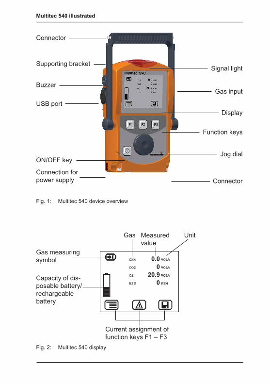
Multitec 540 illustrated
Measured value
Capacity of dis-posable battery/rechargeable battery
Gas measuring symbol
Gas Unit
Current assignment of function keys F1 – F3
Fig. 1: Multitec 540 device overview
Fig. 2: Multitec 540 display
Connector
Buzzer
USB port
ON/OFF key
Connection for power supply
Signal light
Gas input
Function keys
Jog dial
Connector
Display
Supporting bracket
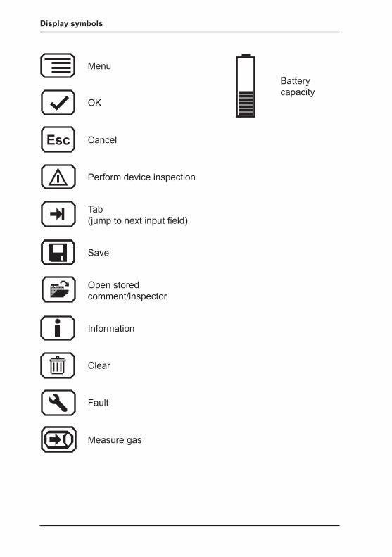
Display symbols
Menu
OK
Esc Cancel
Perform device inspection
Tab (jump to next input field)
Save
Open stored comment/inspector
Information
Clear
Fault
Measure gas
Battery capacity

Operating Instructions
01.08.2011 – V1.XXX – 105832 – en
Multitec® 540
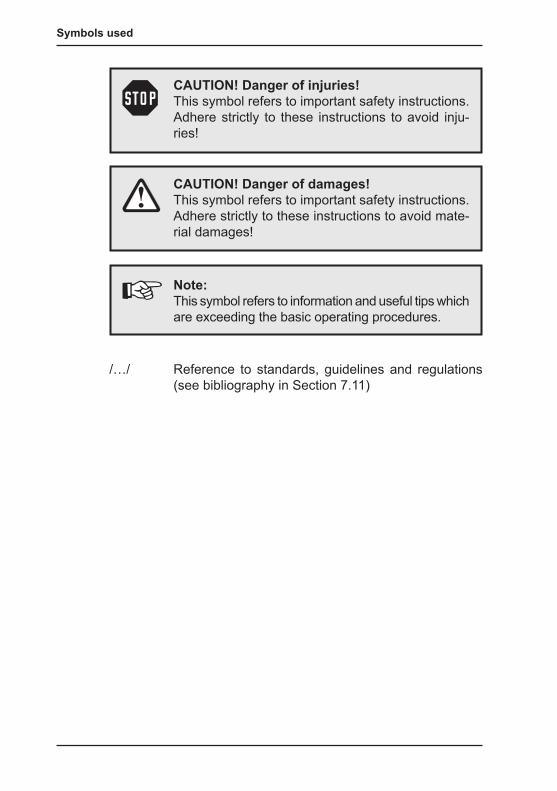
Symbols used
CAUTION! Danger of damages!This symbol refers to important safety instructions. Adhere strictly to these instructions to avoid mate-rial damages!
Note:This symbol refers to information and useful tips which are exceeding the basic operating procedures.
CAUTION! Danger of injuries!This symbol refers to important safety instructions. Adhere strictly to these instructions to avoid inju-ries!
/…/ Reference to standards, guidelines and regulations (see bibliography in Section 7.11)
I
Contents Page
1 General .....................................................................................11.1 Warranty ...................................................................................11.2 Purpose .....................................................................................21.3 Intended use .............................................................................31.4 General safety information ........................................................4
2 Features ...................................................................................52.1 Visual and audible signals .........................................................52.2 Sensors .....................................................................................52.3 Explosion protection ..................................................................6
3 Operation .................................................................................73.1 General information on operation ..............................................73.1.1 Keys and jog dial ....................................................................73.1.2 Selecting / exiting menus and menu items ..............................83.1.3 Switching on the device .........................................................83.1.4 Differences between measuring mode and settings mode ..103.2 Measuring mode ..................................................................... 113.2.1 Accessing the menu (measuring mode menu structure) ...... 113.2.2 Zero point ............................................................................. 113.2.3 Gas measuring .....................................................................123.2.4 Settings ................................................................................123.2.5 Saving a measurement ........................................................123.2.6 Protocols ..............................................................................133.2.7 Device inspection .................................................................143.2.8 Device info ...........................................................................143.3 Settings ...................................................................................153.3.1 Opening Settings ..................................................................153.3.2 Settings menu structure .......................................................163.3.3 Adjustment ...........................................................................173.3.4 System .................................................................................183.3.5 Date/time ..............................................................................193.3.6 Memory ................................................................................19
4 Power supply .........................................................................204.1 Suitable disposable/rechargeable battery types .....................204.2 Operation with rechargeable batteries ....................................214.2.1 Charging ...............................................................................21
II
Contents Page
4.2.2 Rechargeable battery servicing ............................................224.3 Battery alarm ...........................................................................224.4 Replacing disposable/rechargeable batteries .........................23
5 Maintenance ..........................................................................245.1 Device inspection ....................................................................245.1.1 General information on the device inspection ......................245.1.1.1 Scope ................................................................................245.1.1.2 Frequency .........................................................................245.1.1.3 Documentation ..................................................................245.1.1.4 Integrated device inspection .............................................255.1.1.5 Sequence ..........................................................................265.1.2 Performing the device inspection .........................................265.1.2.1 Accessing the device inspection .......................................265.1.2.2 Concluding the device inspection......................................275.1.3 Testing the general status ....................................................295.1.3.1 Housing .............................................................................295.1.3.2 Signals ..............................................................................295.1.3.3 Probe.................................................................................295.1.3.4 Filter ..................................................................................305.1.3.5 Pump .................................................................................305.1.4 Testing indication accuracy with supply of fresh air .............315.1.5 Testing indication accuracy with supply of test gas ..............315.2 Adjustment ..............................................................................335.2.1 Scope ...................................................................................335.2.2 Preparation ...........................................................................335.2.3 Carry out adjustment ............................................................335.2.3.1 Adjusting the zero point.....................................................345.2.3.2 Adjusting sensitivity ...........................................................345.2.4 Carrying out oxygen adjustment ..........................................355.2.4.1 Adjusting the zero point for oxygen ...................................355.2.4.2 Adjusting the sensitivity for oxygen ...................................365.3 Servicing .................................................................................37
6 Faults ......................................................................................38
7 Appendix ................................................................................397.1 Specifications and permitted operating conditions ..................397.2 Limit values for the device inspection .....................................40
III
Contents Page
7.3 Memory capacity .....................................................................407.4 Sensors ...................................................................................417.4.1 Infra red sensors (IR) ...........................................................417.4.1.1 Methane CH4 ....................................................................417.4.1.2 Carbon dioxide CO2 .........................................................417.4.2 Electrochemical sensors (EC) ..............................................427.4.2.1 Oxygen O2 ........................................................................427.4.2.2 Hydrogen sulphide H2S .....................................................427.5 Technical information ..............................................................437.5.1 Identification sticker (back of device) ...................................437.5.2 Cleaning ...............................................................................437.5.3 Electrostatic charge ..............................................................437.6 Accessories: ............................................................................447.7 Declaration of conformity ........................................................507.8 Inspection protocol ..................................................................517.9 Advice on disposal ..................................................................527.10 Terminology and abbreviations ...............................................537.11 Referenced documents ...........................................................54
8 Index .......................................................................................55
1
1 General
1 General
1.1 Warranty The following instructions must be complied with in order for any warranty to be applicable regarding functionality and safe opera-tion of this equipment.Hermann Sewerin GmbH cannot be held responsible for any dam-ages resulting from non-compliance with these instructions. The warranty and liability provisions of the terms of sale and delivery of Hermann Sewerin GmbH are not affected by the information given below.
z Do not operate this product until you have read and understood the relevant operating instructions. z The product must only be used for its intended purpose. z Repairs must only be carried out by a specialist technician or by other suitably trained personnel. z Changes or modifications to this product must not be carried out without approval from Hermann Sewerin GmbH. The manu-facturer cannot be held responsible for damages if unapproved modifications have been made. z Only accessories supplied by Hermann Sewerin GmbH may be used with this product. z All repairs must be carried out using replacement parts that have been approved by Hermann Sewerin GmbH. z Only use the appropriate type of disposable/rechargeable bat-tery, otherwise the device will not be explosion-proof. z The manufacturer reserves the right to make technical modifi-cations in the course of further development.
Generally applicable safety and accident-prevention regulations must be complied with, in addition to the information provided in this manual.
2
1 General
1.2 PurposeThe Multitec 540 is a gas measuring device for monitoring gas mixtures that are formed in biological processes (biogas, landfill gas). It measures the concentration of several gases in the gas mixture simultaneously. The device is ideal for use in waste dis-posal sites, sewage plants and biogas plants.The Multitec 540 is fitted with infrared sensors for measuring methane CH4 and carbon dioxide CO2 as standard. It can also be fitted with electrochemical sensors.
Note:These operating instructions refer to the Multitec 540 with all additional equipment. They explain the func-tions of firmware version 1.XXX. The manufac-turer reserves the right to make technical changes. All descriptions refer to the device as delivered (fac-tory settings).

3
1 General
1.3 Intended useThis device is intended for professional residential and commercial use including small firms and commercial operations. The appro-priate specialist knowledge is required to operate the device.
The device may be used to measure the following gases (depend-ing on the sensors fitted).
zMethane CH4
z Carbon dioxide CO2
z Oxygen O2
z Hydrogen sulphide H2SIf the device is used in closed spaces these must be well ven-tilated.
It should not be used for: zWarning of dangerous gas concentrations zMonitoring liquids
The device can be used up to a temperature of 40 ºC. However, high temperatures reduce the lifetime of the sensors and re-chargeable batteries.If a device with an electrochemical sensor is exposed to con-centrations above the measuring range limit, this can reduce the lifetime of the sensor.
4
1 General
1.4 General safety information z The Multitec 540 is a gas measuring device as opposed to a gas warning instrument. It does not, therefore, warn of danger-ous toxic and explosive gas concentrations or lack of oxygen. If you suspect dangerous gas concentrations, always take along a gas warning instrument too. z Observe the relevant safety regulations when working at agri-cultural biogas plants/1/. z The work area must be well ventilated. z The device has been tested to ensure that it is explosion-proof in accordance with European standards (CENELEC). z Do not use this device in oxygen-enriched atmospheres, oth-erwise it will not be explosion-proof. z Only probe hoses with a hydrophobic filter may be used.Exception: If the probe has a built-in hydrophobic filter, the hose does not require any other filters. z Devices may only be tested with test gases in well ventilated areas or outdoors. Test gases must be handled in a profes-sional manner. z Always carry out a device inspection (see Section 5.1) after the device has suffered an impact (for example, if dropped accidentally). z The device complies with the limits of the EMC directive. Al-ways observe the information in the manuals of (mobile) ra-dio equipment when using the device close to (mobile) radio equipment.
CAUTION!Follow the advice regarding explosion protection (see Section 2.3).
5
2 Features
2 Features
2.1 Visual and audible signalsThe device features two alarms:
z Signal light on top of device(visual signal) z Buzzer on side of device (audible signal)
The signals indicate faults (see Section 6). The device also emits signals when it is switched on and off.
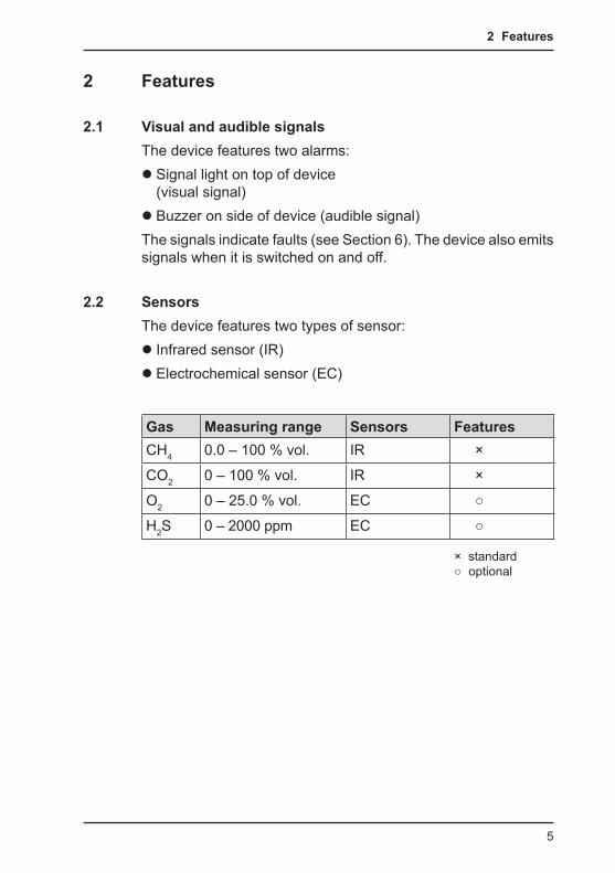
2.2 SensorsThe device features two types of sensor:
z Infrared sensor (IR) z Electrochemical sensor (EC)
Gas Measuring range Sensors FeaturesCH4 0.0 – 100 % vol. IR ×
CO2 0 – 100 % vol. IR ×
O2 0 – 25.0 % vol. EC ○
H2S 0 – 2000 ppm EC ○
× standard○ optional
6
2 Features
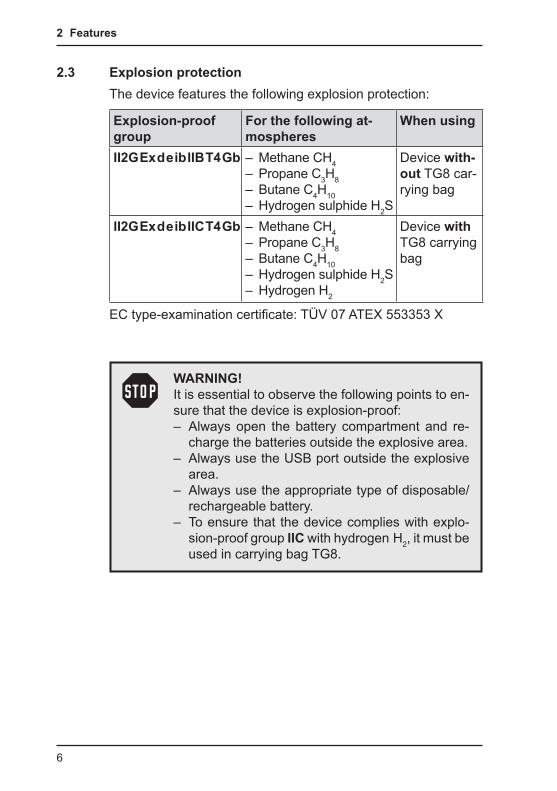
2.3 Explosion protectionThe device features the following explosion protection:
Explosion-proof group
For the following at-mospheres
When using
II2G Ex d e ib IIB T4 Gb – Methane CH4 – Propane C3H8 – Butane C4H10 – Hydrogen sulphide H2S
Device with-out TG8 car-rying bag
II2G Ex d e ib IIC T4 Gb – Methane CH4 – Propane C3H8 – Butane C4H10 – Hydrogen sulphide H2S – Hydrogen H2
Device with TG8 carrying bag
EC type-examination certificate: TÜV 07 ATEX 553353 X
WARNING! It is essential to observe the following points to en-sure that the device is explosion-proof: – Always open the battery compartment and re-
charge the batteries outside the explosive area. – Always use the USB port outside the explosive
area. – Always use the appropriate type of disposable/
rechargeable battery. – To ensure that the device complies with explo-
sion-proof group IIC with hydrogen H2, it must be used in carrying bag TG8.

7
3 Operation
3 Operation
3.1 General information on operation
3.1.1 Keys and jog dialThe ON/OFF key is the only control on the device that does not change its function.When switched on, the device is operated using the jog dial and function keys to navigate the display.
Control Action FunctionON/OFF key Press z Switches the device on
z Switches the device offFunction keys F1, F2, F3
Press z Variable z As indicated on the display at the bottom of the screen z Function keys may also have no function assigned in some cases.
Jog dial Turn z Selects functions, settings, measurement data, etc. zModifies values
Press z Opens the next program level (e. g. menu item, function, measurement data, selectable values) z Applies values
8
3 Operation
3.1.2 Selecting / exiting menus and menu itemsFunctions and settings etc. are selected via the main menu (for short: menu). This menu has submenus and menu items. Refer to Section 3.2.1 for information on accessing the main menu.
Selecting submenus / menu itemsSubmenus and menu items are selected and opened using the jog dial and/or the function keys (see Section 3.1.1).The name of the selected menu or menu item is always shown at the top left of the display.
Exiting menus / menu itemsThere are generally two ways to exit open menus / menu items and return to the next level up:
z Press Esc. z Select Back from the menu.
3.1.3 Switching on the device
Note:Always switch the device on with fresh air.
z Press the ON/OFF key. The device switches on.A visual and audible signal confirm that the device has been switched on. The display and the pump come on.The start screen appears on the display.
9
3 Operation
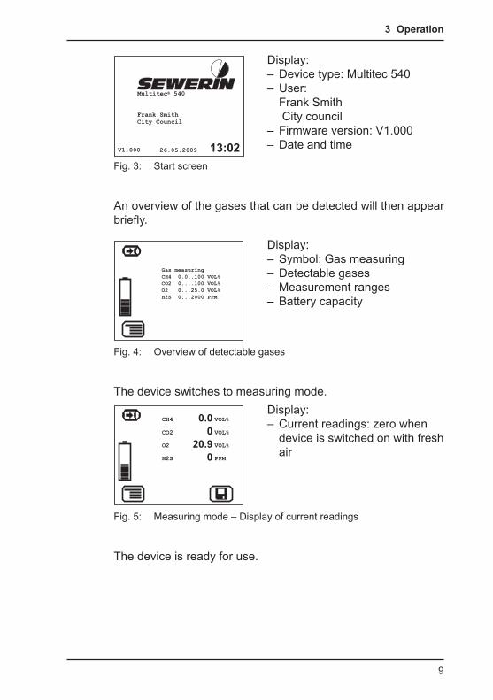
Fig. 3: Start screen
Display: – Device type: Multitec 540 – User: Frank Smith City council
– Firmware version: V1.000 – Date and time
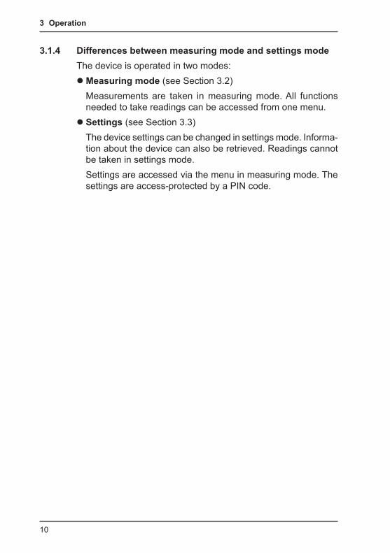
An overview of the gases that can be detected will then appear briefly.
Display: – Symbol: Gas measuring – Detectable gases – Measurement ranges – Battery capacity
Fig. 4: Overview of detectable gases
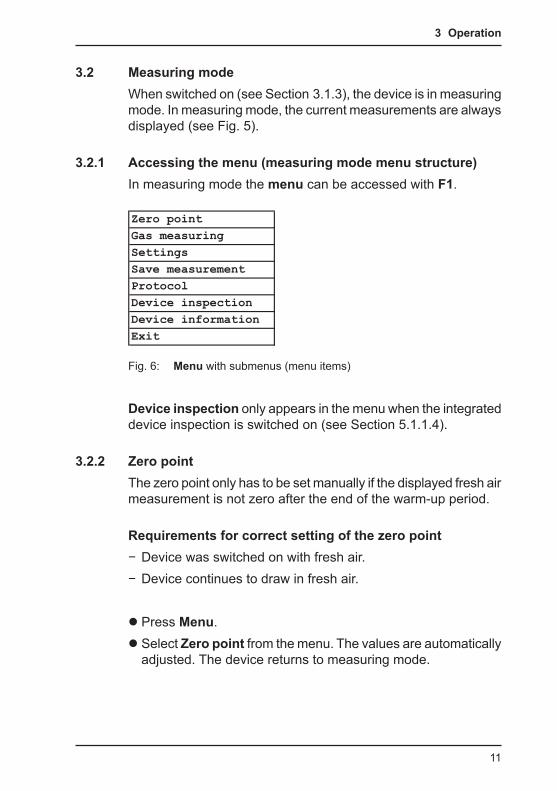
The device switches to measuring mode.Display: – Current readings: zero when device is switched on with fresh air
Fig. 5: Measuring mode – Display of current readings
The device is ready for use.
10
3 Operation
3.1.4 Differences between measuring mode and settings modeThe device is operated in two modes:
zMeasuring mode (see Section 3.2)Measurements are taken in measuring mode. All functions needed to take readings can be accessed from one menu. z Settings (see Section 3.3)The device settings can be changed in settings mode. Informa-tion about the device can also be retrieved. Readings cannot be taken in settings mode.Settings are accessed via the menu in measuring mode. The settings are access-protected by a PIN code.
11
3 Operation
3.2 Measuring modeWhen switched on (see Section 3.1.3), the device is in measuring mode. In measuring mode, the current measurements are always displayed (see Fig. 5).
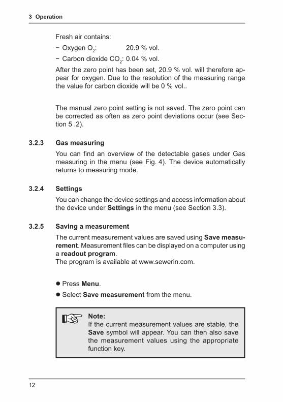
3.2.1 Accessing the menu (measuring mode menu structure)In measuring mode the menu can be accessed with F1.
Fig. 6: Menu with submenus (menu items)
Device inspection only appears in the menu when the integrated device inspection is switched on (see Section 5.1.1.4).
3.2.2 Zero pointThe zero point only has to be set manually if the displayed fresh air measurement is not zero after the end of the warm-up period.
Requirements for correct setting of the zero point − Device was switched on with fresh air. − Device continues to draw in fresh air.
z Press Menu. z Select Zero point from the menu. The values are automatically adjusted. The device returns to measuring mode.
Zero pointGas measuringSettingsSave measurementProtocolDevice inspectionDevice informationExit
12
3 Operation
Fresh air contains: − Oxygen O2: 20.9 % vol. − Carbon dioxide CO2: 0.04 % vol.
After the zero point has been set, 20.9 % vol. will therefore ap-pear for oxygen. Due to the resolution of the measuring range the value for carbon dioxide will be 0 % vol..
The manual zero point setting is not saved. The zero point can be corrected as often as zero point deviations occur (see Sec-tion 5 .2).
3.2.3 Gas measuringYou can find an overview of the detectable gases under Gas measuring in the menu (see Fig. 4). The device automatically returns to measuring mode.
3.2.4 SettingsYou can change the device settings and access information about the device under Settings in the menu (see Section 3.3).
3.2.5 Saving a measurementThe current measurement values are saved using Save measu-rement. Measurement files can be displayed on a computer using a readout program. The program is available at www.sewerin.com.
z Press Menu. z Select Save measurement from the menu.
Note:If the current measurement values are stable, the Save symbol will appear. You can then also save the measurement values using the appropriate function key.
13
3 Operation
z If necessary, enter a comment on the measurement. − Select the characters required using the jog dial. Confirm each character using the jog dial.OR
− Press Open saved comment. A list of the saved comments will appear. Select the desired comment. Open the comment with OK.
Note:Comment entries are saved automatically. The last 10 comments entered (maximum) will be saved. Once the first comment has been entered, the Open saved comment function will become available.
z Confirm your entry/selection with OK. The comment is saved together with the protocol name (date, time).
Note:If you do not need to enter a comment, you can also skip the input field by pressing Esc. The measure-ment is still saved.
3.2.6 ProtocolsYou can retrieve or clear protocols of saved data under the Pro-tocols menu item. When saved, the protocols are assigned to different protocol types.The following protocol types are available:
z Device inspection zMeasurements
Protocols can only be cleared individually.You can find information on how to clear all protocols of the same protocol type in Section 3.3.6.

14
3 Operation
3.2.7 Device inspectionDevice inspection only appears in the menu when the integrated device inspection is switched on. The device inspection can be used to check the general status and the indication accuracies.
Note:The integrated device inspection is switched off in the factory settings. More detailed information about the device inspection can be found in Section 5.1.
If the integrated device inspection is switched on, the device will remind you every 3 months to perform a device inspection.
The symbol will appear when the device inspection is due. It is visible in the display until the complete integrated device inspection has been carried out successfully.
3.2.8 Device infoThe following device information is shown under Device infor-mation in the menu.
z Installed electrochemical sensors: gas, installation date, warranted/expected lifetime z Firmware: version, date z Service: date of the last service, date of the next service
15
3 Operation
3.3 SettingsThe following menus and menu items are included under Settings (see Sections 3.3.3 to 3.3.6):
z Adjustment z System z Date/time zMemory
You can find information on selecting and exiting menus and menu items in Section 3.1.2.
3.3.1 Opening Settings z Press Menu. z Select the Settings menu item.
Access is protected by a PIN code. The default setting is always PIN code 0001.After opening Settings, you can change the PIN code (see Sec-tion 3.3.4). It is advisable to set a different PIN code after initial start-up, so only authorised personnel have access to the set-tings.
z Enter the PIN code from left to right. The active digit is always displayed with a black background.
Digit To change: To confirm:1st digit
Turn the jog dial.
Push the jog dial.2nd digit Push the jog dial.3rd digit Push the jog dial.4th digit
If the PIN code has been entered correctly, the Settings menu will appear once the last digit has been confirmed (see Fig. 7). Otherwise the device will revert to measuring mode.

16
3 Operation
Fig. 7: Settings menu
3.3.2 Settings menu structure
AdjustmentSystemDate/timeMemoryExit
PIN CodeSettings Adjustment Adjustment CH4
Adjustment CO2Adjustment O2Adjustment H2STest gasInspection OKExit
System PIN CodeService intervalDisplayBatteryAutostartDevice inspectionResetLanguageExit
Date/time
Memory ClearIntervalMemory modeExit
Exit
Measuring mode
Fig. 8: Multitec 540 Settings menu structure
Note:The number and names of available menu items depend on the device model and optional additional equipment.
17
3 Operation
3.3.3 AdjustmentThe Adjustment menu is used to set the sensors.
WARNING! The device must only be adjusted by specialist technicians in well ventilated rooms or in the open air. Incorrect adjustment can lead to incorrect meas-urement results.
More detailed information about adjustment can be found in Sec-tion 5.2.
CH4 adjustmentAdjusts the infrared sensor for methane CH4 in the % vol. range.
CO2 adjustmentUsed to adjust the infrared sensor for carbon dioxide CO2 in the % vol. range.
O2 adjustmentAdjusts the electrochemical sensor for oxygen O2 in the % vol. range.
H2S adjustmentAdjusts the electrochemical sensor for hydrogen sulphide H2S in the ppm range.
Test gas Adjusts the concentration of the test gases used.
Inspection OKConfirms the device is in proper working order. This extends the service interval.
18
3 Operation
3.3.4 SystemGeneral information and specifications for operation are set in the System menu.
PIN codeUsed to change or reset the PIN code.
Note:If the PIN code is set to 0000, you will not be asked to enter the PIN code. The settings can then be ac-cessed by anyone.If you lose the PIN code, you must contact SEWERIN Service.
Service intervalSpecify the regular inspections/maintenance required for the de-vice. You can also activate the automatic switch-off function once the set interval has passed.
DisplayUsed to set how long the display remains illuminated after any button is pressed as well as the display contrast.
BatteryUsed to set the type of disposable/rechargeable battery used.
CAUTION!The disposable/rechargeable battery type setting must always be correct to prevent damage to the device.
AutostartThis setting cannot be changed.
19
3 Operation
Device inspectionSwitches the integrated device inspection on and off.
ResetUse to reset the device settings to the factory settings.
LanguageSets the language.
3.3.5 Date/timeUsed to set the time, day, month, and year. There are two formats available for the date.
3.3.6 MemoryThe Memory menu is used to specify how measurement data and protocols are handled.
ClearUsed to clear protocols.The two different protocol types must each be cleared separately. All protocols in one protocol type are cleared at once.You can find information on clearing individual protocols in Sec-tion 3.2.6.
IntervalSet the interval at which measurement data is automatically saved.
Memory modeSwitches between ring memory and stack memory.
20
4 Power supply
4 Power supplyThis device can be operated using:
z Disposable (non-rechargeable) alkaline batteries z Rechargeable NiMH batteries
The device comes with nickel metal hydride rechargeable batter-ies. The corresponding settings are stored.
WARNING!The device must not be used with leaking batter-ies. Replace the disposable/rechargeable batteries. Clean the battery compartment (and, if necessary, the device) before inserting the new disposable/rechargeable batteries.
4.1 Suitable disposable/rechargeable battery types
WARNING!To ensure that the device remains explosion-proof as per /6/, only the following disposable/recharge-able batteries may be used: – Batteries supplied by SEWERIN – Others offered by SEWERIN, provided observ-
ance as per /3/ is guaranteed.The battery types used in one battery compartment must always be identical in terms of sort (disposable/rechargeable), capacity and manufacturer.
Disposable battery requirements z Alkaline disposable batteries z Battery size: AA, Type: LR6 as per /4/ z The creepage distance and air gap between the poles must not be less than 0.5 mm in accordance with /3/.

21
4 Power supply
Rechargeable battery requirements z NiMH rechargeable batteries z Battery size: AA, Type: HR6 as per /5/ z The creepage distance and air gap between the poles must not be less than 0.5 mm in accordance with /3/. z The rechargeable batteries must be fast charging (I > 1.25 A) and remain within the temperature range.
CAUTION!A device operated with disposable alkaline batteries cannot be charged. A notice to this effect is shown on the display.
4.2 Operation with rechargeable batteriesThe operating time of the device depends on the battery capac-ity.If the device is not used or not kept in the docking station, the rechargeable batteries will lose their charge after 30 days at the latest ( self-discharge).
4.2.1 ChargingThe device can be charged via:
z Connection for power supply z Docking station TG8
For charging you will need either: z AC/DC adapter M4 z Vehicle cable M4
Please note the following points: z The device/docking station must not be directly connected to a 24-V on-board power supply in the vehicle. The voltage is too high for the charging process. z The battery should be charged at approximately room tem-perature.
22
4 Power supply
z Short operating times and long periods out of use can reduce the available battery capacity (memory effect).
4.2.2 Rechargeable battery servicingIf the device is not used for a long period of time, it is recommend-ed to fully discharge the battery before recharging it again.
WARNING! The device must only be discharged outside of the explosive area.
z Connect the device (switched on) to the power supply via the side connection
OR z Place the device (switched on) into the docking station.The rechargeable batteries will be fully discharged. Once the device has been discharged, it will automatically switch to charging mode.
A full discharging and recharging process takes approx. 11 hours (8 hrs discharging + 3 hrs. recharging). The duration depends on the capacity of the batteries used.
4.3 Battery alarm As soon as the remaining capacity of the disposable/recharge-able battery gets low, a battery alarm will go off:
Level 1: Disposable/rechargeable battery almost empty: – Capacity of disposable/rechargeable battery symbol flashes
– Audible signal (one-off) – Remaining operating time: approx. 15 min
Level 2: Disposable/rechargeable battery empty: – Blank display apart from Capacity of disposable battery/rechargeable battery symbol
– Continuous audible signal – Measuring mode unavailable – Device shuts off

23
4 Power supply
4.4 Replacing disposable/rechargeable batteries
WARNING! Disposable/rechargeable batteries must always be replaced outside of the explosive area.
A 2.5 mm Allen key (supplied) is required to open the battery compartment on the back of the device.
z Loosen the two screws securing the battery compartment. Remove the screws by repeatedly turning each one a short distance in alternation; this ensures that the battery compart-ment does not twist. z Lift out the battery compartment. z Remove the disposable/rechargeable batteries and insert new ones. Ensure that the batteries are inserted with the correct polarity. z Replace the battery compartment so it fits neatly into place and secure firmly with the screws. zWhen you switch the device back on again, you will be asked which battery type is in use. Enter the correct battery type.
If it takes longer than 120 seconds to change the batteries, the date and time will have to be reset the next time you switch the device on. All the other data will be saved.
24
5 Maintenance
5 MaintenanceIn accordance with the legal regulations, device maintenance comprises the following elements:
z Device inspection including test of indication accuracy z Adjustment z Servicing
All inspections must be documented. The documentation must be retained for at least one year.
5.1 Device inspection
5.1.1 General information on the device inspection
5.1.1.1 ScopeThe device inspection includes the following tests:
z Analysis of the general status (see Section 5.1.3) z Test of the indication accuracy with supply of fresh air (see Section 5.1.4) z Test of the indication accuracy with supply of test gas (see Section 5.1.5)
5.1.1.2 FrequencyThe device inspection must be carried out at intervals ranging from once a week to every six months /2/.If the integrated device inspection is switched on, the device will remind you every 3 months to perform a device inspection.
5.1.1.3 DocumentationThe device inspection procedure must be documented. There are two ways of doing this:
z On paper z Saved electronically supported by the device (integrated de-vice inspection)
25
5 Maintenance
Only the integrated device inspection is described in these op-erating instructions.
Note:The device inspection must be documented on pa-per if the integrated device inspection is switched off.
5.1.1.4 Integrated device inspection
Note:The integrated device inspection is switched off in the factory settings.
The results of the integrated device inspection are stored in the device as a protocol. They can be displayed on a computer using a readout program.
This symbol appears in the display when a device inspection is due. It is visible in the display until the complete integrated device inspection has been car-ried out successfully. If the device inspection was completed but the device failed on some points (not OK), the symbol will remain visible.
Switching on the device inspection z Press Menu. z Select Settings. z Enter your PIN code. z Select System. z Select device inspection. z Select Yes. z Apply the setting with OK. z Exit the Settings with Back.
26
5 Maintenance
5.1.1.5 SequenceYou can carry out the tests that make up the device inspection in any order you wish. You can repeat the tests as often as you wish provided you have not yet concluded the device inspection.
5.1.2 Performing the device inspection
5.1.2.1 Accessing the device inspectionThe device is in measuring mode.
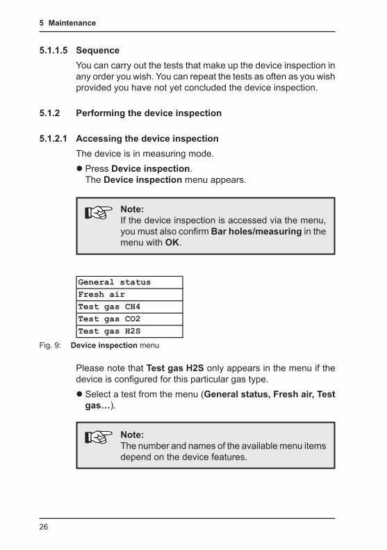
z Press Device inspection. The Device inspection menu appears.
Note:If the device inspection is accessed via the menu, you must also confirm Bar holes/measuring in the menu with OK.
Fig. 9: Device inspection menu
General statusFresh airTest gas CH4Test gas CO2Test gas H2S
Please note that Test gas H2S only appears in the menu if the device is configured for this particular gas type.
z Select a test from the menu (General status, Fresh air, Test gas…).
Note:The number and names of the available menu items depend on the device features.
27
5 Maintenance
z Carry out the test.For detailed information, refer to the following sections:
− General Status Section 5.1.3 − Fresh air Section 5.1.4 − Test gas … Section 5.1.5
5.1.2.2 Concluding the device inspectionAfter all the tests have been carried out as described in Sec-tions 5.1.3 to 5.1.5, the Save symbol will appear in the display. The device inspection can be concluded.
z Press Save. z If necessary enter the name of the inspector.
− Select the characters required using the jog dial. Confirm each character using the jog dial.OR
− Press Open saved inspector. A list of the saved inspectors will appear. Select the desired inspector. Open the inspec-tor with OK.
Note:Inspector entries are saved automatically. The last 10 inspectors entered (maximum) will be saved. Once the first inspector has been entered, the Open saved inspector function will become available.
z Confirm your entry/selection with OK. z Enter a password if necessary. Select the characters required using the jog dial. Confirm each character using the jog dial. z Confirm your entry with OK. The device inspection is saved as a protocol. A comprehensive overview with the device inspec-tion results is displayed. z Confirm the overview by pressing OK. The device returns to measuring mode.

28
5 Maintenance
Note:If you do not need to enter an inspector or a pass-word, these input fields can be skipped by press-ing Esc. The device inspection is still saved as a protocol.
The device inspection protocols can be opened at any time (see Section 3.2.6). The number is limited to a maximum of 40.
29
5 Maintenance
5.1.3 Testing the general statusThe general status test is part of the device inspection (see Sec-tion 5.1.1.1). It is based on estimations by the user. The following must be tested:
z Housing z Signals z Probe z Filter z Pump
The battery charge status and the working condition of the com-ponents are automatically tested during the integrated device inspection.
z Select General status from the Device inspection menu. z Test all associated subitems as described in Sections 5.1.3.1 to 5.1.3.5. z Confirm the prompt General status OK? by pressing Yes if all subitems show no faults during testing. General status OK appears on the display.
5.1.3.1 Housing z Is the housing free from external damage?
5.1.3.2 SignalsDuring the integrated device inspection the signals are emitted at short intervals.
z Can the audible signal be heard? z Is the visual signal visible?
5.1.3.3 ProbeProbes are accessories. They must only be tested if they are likely to be used in the course of the work day.
z Are the probes free from external damage?Probe hoses are tested with a simple leak-tightness check.
30
5 Maintenance
z Connect the probe hose to the gas input. z Seal the free end of the probe hose.An error message should appear after approximately 10 sec-onds. This indicates that the probe hose is in good condition.
5.1.3.4 FilterThefine dust filter is located behind the gas input. It is tested by means of a visual inspection.
z Unscrew the gas input. z Remove the fine dust filter. z Check that there is no dirt in the fine dust filter.As soon as there are any signs of depositing, the filter must be replaced. If you do not replace the filter, you must reinsert it exactly as it was removed.
5.1.3.5 PumpThe pump function is tested with a simple leak check.
z Seal the gas input.After a maximum of 10 seconds an error message should ap-pear. This indicates that the pump is working correctly.If the error message does not appear, the pump may be faulty. The device must be tested by SEWERIN Service. z Release the gas input again.After approximately seconds, the error message should disap-pear again. Otherwise there is an error (see Section 6).
31
5 Maintenance
5.1.4 Testing indication accuracy with supply of fresh airThe indication accuracy with supply of fresh air test is part of the device inspection (see Section 5.1.1.1).Ensure that the fresh air used for testing is sufficiently pure.
z Select Fresh air from the Device inspection menu. zWait until the displayed readings are stable. A Status: OK message appears. z Press OK to confirm. Fresh air OK appears on the display.
If the Status: OK message does not appear within a reasonable amount of time, the air inflow does not correspond to the limit values stored in the device (see Section 7.2). Move the device somewhere else and repeat the test.If the Status: OK message still does not appear when the test is repeated, the device must be re-adjusted (see Section 5.2).
5.1.5 Testing indication accuracy with supply of test gasThe indication accuracy with supply of test gas test is part of the device inspection (see Section 5.1.1.1).
z Select the gas to be tested (test gas CH4, test gas CO2, test gas H2S) from the Device inspection menu. z Check whether the test gas concentration specified by the device matches the test gas you intend to use. Press Infor-mation. z Add the gas to be tested. Connect the test gas to the gas in-put. zWait until the displayed readings are stable. A Status: OK message appears. z Press OK to confirm. z Remove the test gas.
If the Status: OK message does not appear within a reasonable amount of time, the following causes are possible:
32
5 Maintenance
Cause Corrective actionConnections leaking Repeat check, checking for the
seal on the connectionsMeasurement values outside the specified limit values (see Section 7.2)
Adjustment required (see Section 5.2)
Note:The Test gas OK message only appears when all the test gases specified in the device inspection have been successfully tested.
Changing the test gasIf no test gas with the specified concentrations is available for the test, the values can be changed accordingly under Test gas in the adjustment menu (see section 3.3.3).

33
5 Maintenance
5.2 Adjustment
WARNING! The device must only be adjusted by specialist technicians in well ventilated rooms or in the open air. Incorrect adjustment can lead to incorrect meas-urement results.
5.2.1 ScopeThe following are adjusted:
z Zero point zMeasuring range sensitivity
CAUTION!Always adjust the zero point first, followed by the sensitivity.
It is not essential to adjust all gases during adjustment. Every gas must be adjusted separately.
5.2.2 PreparationCarrying out an adjustment always takes some time. Leave your-self plenty of time to prepare the necessary steps of the proce-dure. Have all necessary tools available. Let the device run for several minutes, to guarantee, for example, that the temperature is right.
5.2.3 Carry out adjustmentAdjustment of the zero point and the sensitivity is carried out fol-lowing the same procedure for all gases (see Sections 5.2.3.1 and 5.2.3.2). The adjustment of oxygen is an exception. For this reason it is described separately (see Section 5.2.4).
34
5 Maintenance
You can access detailed information on the adjust-ment of the various gases (for example, test gas, installation date of the sensor, or date of the last ad-justment) under Information.This symbol appears after the respective Adjust-ment … has been selected from the menu.
5.2.3.1 Adjusting the zero pointFor all gases except oxygen O2, the zero point is adjusted follow-ing the same procedure.
Note:When adjusting the zero point of carbon diox-ide CO2, a carbon dioxide filter must be used.
z Select the desired adjustment from the Adjustment menu (for example, CH4 adjustment). zWait at least 1 minute. The displayed reading must be stable. z Select Zero point from the menu (select and confirm with OK). This adjusts the zero point. The reading shows zero (0.00 % vol. or 0 ppm).
5.2.3.2 Adjusting sensitivityFor all gases except oxygen O2, the sensitivity is adjusted follow-ing the same procedure.A test set (such as SPE VOL) is required for adjusting the sen-sitivity.
Note:When adjusting the sensitivity, never use a carbon dioxide filter.
35
5 Maintenance
z Connect the device to the test set. To do so, follow the steps indicated in the test set operating instructions. z Select the desired adjustment from the Adjustment menu (for example, CH4 adjustment). z Select the menu item that specifies the sensitivity to be tested (for example, 100 % VOL CH4). Do not yet confirm with OK. z Press and hold the release button on the test set. The test gas is added. Do not let go of the release button. zWait at least 1 minute. The displayed reading must be stable. z Press OK to confirm. The device is adjusted. The reading shows the specified value (e. g. 100 % vol. CH4). z Let go of the release button on the test set.
5.2.4 Carrying out oxygen adjustmentAs oxygen is a component of fresh air, the procedure for adjusting oxygen is different than the procedure for all other gases.
5.2.4.1 Adjusting the zero point for oxygenThe zero point for oxygen must be adjusted using an inert gas which contains no oxygen and does not damage the sensor. For example, suitable test gases include 100 % vol. CH4 or 100 % vol. N2.A test set (such as SPE VOL) is required for adjusting the zero point.
z Connect the device to the test set. To do so, follow the steps indicated in the test set operating instructions. z Select Adjustment O2 from the Adjustment menu. z Select Zero point from the menu. Do not yet confirm with OK. z Press and hold the release button on the test set. The test gas is added. Do not let go of the release button. zWait at least 1 minute. The displayed reading must be stable.
36
5 Maintenance
z Press OK to confirm. The device is adjusted. The reading shows zero (0.0 % vol.). z Let go of the release button on the test set.
5.2.4.2 Adjusting the sensitivity for oxygenThe sensitivity of oxygen is adjusted with fresh air.
z Select Adjustment O2 from the Adjustment menu. zWait until the displayed reading is stable. (The reading may still flash.) z Select 20.9 % VOL (fresh air) from the menu (select and con-firm with OK). This adjusts the sensitivity. The reading shows 20.9 % vol.
37
5 Maintenance
5.3 ServicingThe device must only be serviced and repaired by SEWERIN Service.
z Send the device to SEWERIN for repairs and for annual main-tenance.
Note:If there is a service agreement in place, the device can be serviced by the mobile maintenance serv-ice.
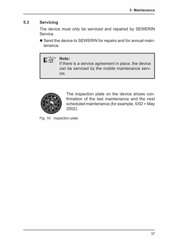
The inspection plate on the device shows con-firmation of the last maintenance and the next scheduled maintenance (for example, 5/02 = May 2002).
Fig. 10: Inspection plate
38
6 Faults
6 FaultsIf a fault occurs during operation, an error message will appear on the screen.Error messages are displayed in the order in which they occur. Up to 5 errors can be displayed. Error messages continue to be displayed until the error is corrected.
Overview of possible error messages
Error code Error message on the display
Error correction
9 No calibrationIR sensor adjustment
CH4 adjustment or CO2 adjustment required (see Section 5.2)
10 Adjustment failedTest gas
Check test gas
52 XFLASHSEWERIN Service
Error can only be corrected by SEWERIN Service
59 Error unknownSEWERIN Service
Error can only be corrected by SEWERIN Service
62 IR sensor Error can only be corrected by SEWERIN Service
100 Pump errorProbe / filter
Check all filters, probes and hose connections for porosity and dirt
200 I2C HOST – IRSEWERIN Service
Error can only be corrected by SEWERIN Service
201 I2C HOST – ECSEWERIN Service
Error can only be corrected by SEWERIN Service
202 I2C HOST – EXSEWERIN Service
Error can only be corrected by SEWERIN Service
39
7 Appendix
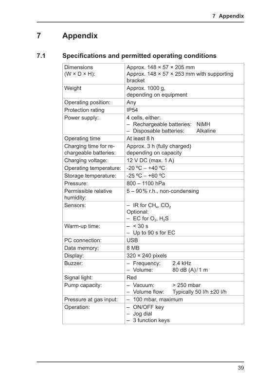
7 Appendix
7.1 Specifications and permitted operating conditionsDimensions (W × D × H):
Approx. 148 × 57 × 205 mmApprox. 148 × 57 × 253 mm with supporting bracket
Weight Approx. 1000 g, depending on equipment
Operating position: AnyProtection rating IP54Power supply: 4 cells, either:
– Rechargeable batteries: NiMH – Disposable batteries: Alkaline
Operating time At least 8 hCharging time for re-chargeable batteries:
Approx. 3 h (fully charged) depending on capacity
Charging voltage: 12 V DC (max. 1 A)Operating temperature: -20 ºC – +40 ºCStorage temperature: -25 ºC – +60 ºCPressure: 800 – 1100 hPaPermissible relative humidity:
5 – 90 % r.h., non-condensing
Sensors: – IR for CH4, CO2
Optional: – EC for O2, H2S
Warm-up time: – < 30 s – Up to 90 s for EC
PC connection: USBData memory: 8 MBDisplay: 320 × 240 pixelsBuzzer: – Frequency: 2.4 kHz
– Volume: 80 dB (A) / 1 mSignal light: RedPump capacity: – Vacuum: > 250 mbar
– Volume flow: Typically 50 l/h ±20 l/hPressure at gas input: – 100 mbar, maximumOperation: – ON/OFF key
– Jog dial – 3 function keys
40
7 Appendix
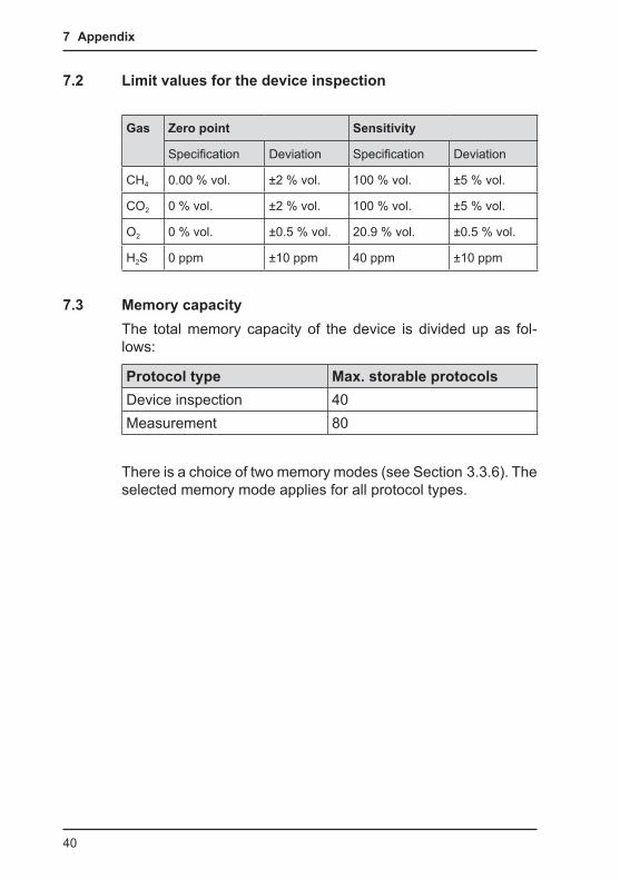
7.2 Limit values for the device inspection
Gas Zero point Sensitivity
Specification Deviation Specification Deviation
CH4 0.00 % vol. ±2 % vol. 100 % vol. ±5 % vol.
CO2 0 % vol. ±2 % vol. 100 % vol. ±5 % vol.
O2 0 % vol. ±0.5 % vol. 20.9 % vol. ±0.5 % vol.
H2S 0 ppm ±10 ppm 40 ppm ±10 ppm
7.3 Memory capacityThe total memory capacity of the device is divided up as fol-lows:
Protocol type Max. storable protocolsDevice inspection 40Measurement 80
There is a choice of two memory modes (see Section 3.3.6). The selected memory mode applies for all protocol types.
41
7 Appendix
7.4 Sensors
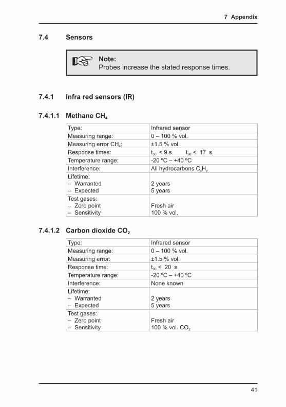
Note:Probes increase the stated response times.
7.4.1 Infra red sensors (IR)
7.4.1.1 Methane CH4 Type: Infrared sensorMeasuring range: 0 – 100 % vol.Measuring error CH4: ±1.5 % vol.Response times: t50 < 9 s t90 < 17 sTemperature range: -20 ºC – +40 ºCInterference: All hydrocarbons CxHy
Lifetime: – Warranted – Expected
2 years5 years
Test gases: – Zero point – Sensitivity
Fresh air100 % vol.
7.4.1.2 Carbon dioxide CO2 Type: Infrared sensorMeasuring range: 0 – 100 % vol.Measuring error: ±1.5 % vol.Response time: t90 < 20 sTemperature range: -20 ºC – +40 ºCInterference: None knownLifetime: – Warranted – Expected
2 years5 years
Test gases: – Zero point – Sensitivity
Fresh air100 % vol. CO2

42
7 Appendix
7.4.2 Electrochemical sensors (EC)
7.4.2.1 Oxygen O2 Type: Electrochemical sensorMeasuring range: 0 – 25 % vol.Resolution: 0.1 % vol.Measuring error: ±3 % or ±0.3. % vol. (±3 digits)Response time: t90 < 15 sDrift: < 2 % within 3 monthsTemperature range: -20 ºC – +40 ºCInterference: None knownLifetime: – Warranted – Expected
2 years3 years
Test gases: – Zero point – Sensitivity
100 % vol. CH4 or 100 % vol. N2
Fresh air (20.9 % vol.)
7.4.2.2 Hydrogen sulphide H2SType: Electrochemical sensorMeasuring range: – Lower limit
0 – 2000 ppm2 ppm
Resolution: 2 ppmMeasuring error: ±3 % or ±6 ppm (±3 digits)
±4 ppm (long-term stability)Zero point deviation: 2 ppmResponse time: t90 < 30 sDecay time: t10 < 27 sDrift: < 10 % within 6 monthsTemperature range: -20 ºC – +40 ºCInterference at 20 ºC – 100 ppm CO – 1 % vol. H2
– 100 ppm NO2
Approx. 2 ppm H2SApprox. 10 ppm H2SApprox. 4 ppm H2S
Lifetime: – Warranted – Expected
1 year> 2 years
Test gases: – Zero point – Sensitivity
Fresh air40 ppm H2S
43
7 Appendix
7.5 Technical information
7.5.1 Identification sticker (back of device)The symbols on the sticker mean the following:
Always open battery compartment outside the explosive area.
Read the operating instructions.
7.5.2 CleaningThe device must only be cleaned with a damp cloth.
CAUTION!Do not use solvents, petrol or cockpit spray con-taining silicone or similar substances to clean the device!
7.5.3 Electrostatic chargeAvoid electrostatically charging the device. Electrostatically unearthed objects (e. g. including metallic housing without an earth connection) are not protected against applied charges (e.g. through dust or dispersed flows).
CAUTION!To prevent electrostatic charging when working with hydrogen H2, always use carrying bag TG8.

44
7 Appendix
7.6 Accessories:
Docking station TG8Art. no.: LP11-10001
z For charging, operating and holding one device z Includes locking mechanism to prevent unit falling out z AC/DC adapter or vehicle ca-ble required for charging and operation
AC/DC adapter M4Art. no.: LD10-10001
z 100 – 240 V~ / 12 V=
Vehicle cable M4 Art. no.: ZL07-10100
z 12 V= mobile, with built-in fuse and cigarette lighter adapter z For mobile use in a vehicle
Vehicle cable M4 Art. no.: ZL07-10000
z 12 V= mounting, includes built-in fuse and female spade connectors z permanently connects unit to the vehicle electrical system

45
7 Appendix
Vehicle cable M4Art. no.: ZL09-10000
z 24 V= mounting, includes volt-age converter and female spade converters z permanently connects unit to the vehicle electrical system
Carrying system "Vario"Art. no.: 3209-0012
z Two adjustable carrying straps with quick release buttons and padded straps z Can be worn around the neck or as a chest harness.
Carrying bag TG8Art. no.: 3204-0040
z Leather, with viewing panel and openings for connections, jog dial and securing the car-rying systems z Easily fitted thanks to Velcro fastener z Can be used in explosive areas
46
7 Appendix
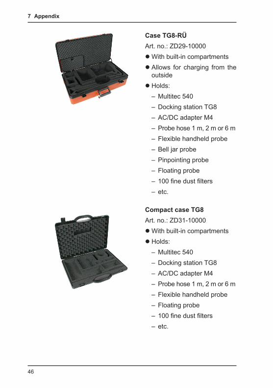
Case TG8-RÜArt. no.: ZD29-10000
zWith built-in compartments z Allows for charging from the outside z Holds:
– Multitec 540 – Docking station TG8 – AC/DC adapter M4 – Probe hose 1 m, 2 m or 6 m – Flexible handheld probe – Bell jar probe – Pinpointing probe – Floating probe – 100 fine dust filters – etc.
Compact case TG8Art. no.: ZD31-10000
zWith built-in compartments z Holds:
– Multitec 540 – Docking station TG8 – AC/DC adapter M4 – Probe hose 1 m, 2 m or 6 m – Flexible handheld probe – Floating probe – 100 fine dust filters – etc.
47
7 Appendix
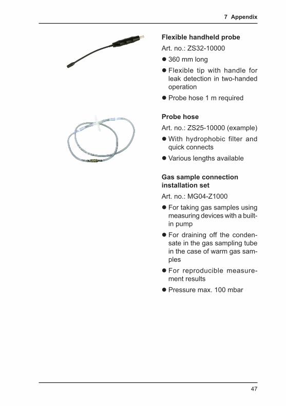
Flexible handheld probeArt. no.: ZS32-10000
z 360 mm long z Flexible tip with handle for leak detection in two-handed operation z Probe hose 1 m required
Probe hoseArt. no.: ZS25-10000 (example)
zWith hydrophobic filter and quick connects z Various lengths available
Gas sample connection installation setArt. no.: MG04-Z1000
z For taking gas samples using measuring devices with a built-in pump z For draining off the conden-sate in the gas sampling tube in the case of warm gas sam-ples z For reproducible measure-ment results z Pressure max. 100 mbar
48
7 Appendix
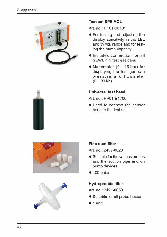
Test set SPE VOLArt. no.: PP01-90101
z For testing and adjusting the display sensitivity in the LEL and % vol. range and for test-ing the pump capacity z Includes connection for all SEWERIN test gas cans zManometer (0 – 16 bar) for displaying the test gas can pressure and f lowmeter (0 – 80 l/h)
Universal test head Art. no.: PP01-B1700
z Used to connect the sensor head to the test set
Fine dust filterArt. no.: 2499-0020
z Suitable for the various probes and the suction pipe end on pump devices z 100 units
Hydrophobic filterArt. no.: 2491-0050
z Suitable for all probe hoses z 1 unit
49
7 Appendix
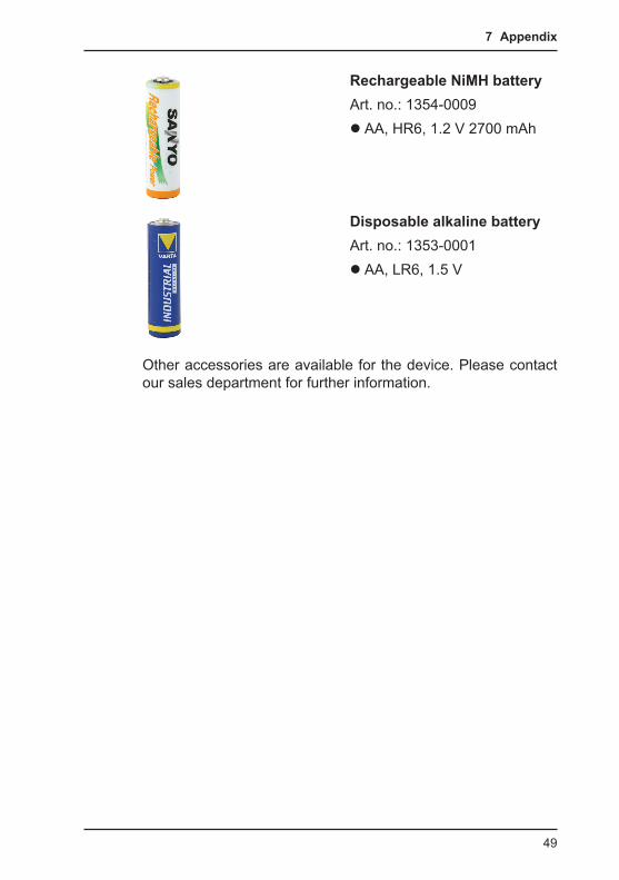
Rechargeable NiMH batteryArt. no.: 1354-0009
z AA, HR6, 1.2 V 2700 mAh
Disposable alkaline batteryArt. no.: 1353-0001
z AA, LR6, 1.5 V
Other accessories are available for the device. Please contact our sales department for further information.
50
7 Appendix
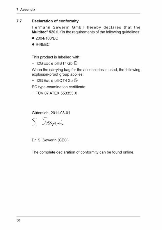
7.7 Declaration of conformityHermann Sewer in GmbH hereby declares that the Multitec® 520 fulfils the requirements of the following guidelines:
z 2004/108/EC z 94/9/EC
This product is labelled with: − II2G Ex d e ib IIB T4 Gb
When the carrying bag for the accessories is used, the following explosion-proof group applies:
− II2G Ex d e ib IIC T4 Gb EC type-examination certificate:
− TÜV 07 ATEX 553353 X
Gütersloh, 2011-08-01
Dr. S. Sewerin (CEO)
The complete declaration of conformity can be found online.
51
7 Appendix
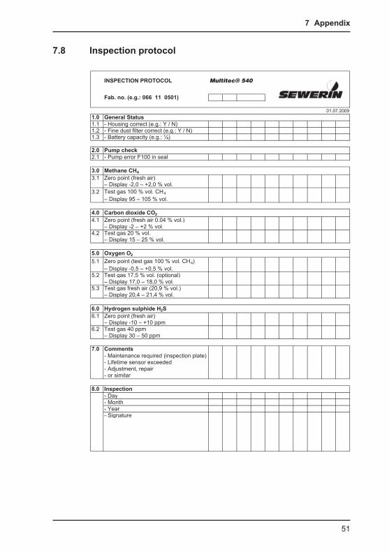
7.8 Inspection protocol
INSPECTION PROTOCOL Multitec® 540
Fab. no. (e.g.: 066 11 0501)
01.07.20091.0 General Status1.1 - Housing correct (e.g.: Y / N)1.2 - Fine dust filter correct (e.g.: Y / N)1.3 - Battery capacity (e.g.: ¼)
2.0 Pump check2.1 - Pump error F100 in seal
3.0 Methane CH4 3.1 Zero point (fresh air)
– Display -2,0 – +2,0 % vol.3.2 Test gas 100 % vol. CH4
– Display 95 – 105 % vol.
4.0 Carbon dioxide CO2 4.1 Zero point (fresh air 0.04 % vol.)
– Display -2 – +2 % vol.4.2 Test gas 20 % vol.
– Display 15 – 25 % vol.
5.0 Oxygen O2
5.1 Zero point (test gas 100 % vol. CH4)– Display -0,5 – +0,5 % vol.
5.2 Test gas 17,5 % vol. (optional)– Display 17,0 – 18,0 % vol.
5.3 Test gas fresh air (20,9 % vol.)– Display 20,4 – 21,4 % vol.
6.0 Hydrogen sulphide H2S6.1 Zero point (fresh air)
– Display -10 – +10 ppm6.2 Test gas 40 ppm
– Display 30 – 50 ppm
7.0 Comments- Maintenance required (inspection plate)- Lifetime sensor exceeded- Adjustment, repair- or similar
8.0 Inspection- Day- Month- Year- Signature

52
7 Appendix
7.9 Advice on disposalThe European Waste Catalogue (EWC) governs the disposal of appliances and accessories.
Description of waste Allocated EWC waste code
Device 16 02 13
Test gas can 16 05 05
Disposable battery, rechargeable battery
16 06 05
End-of-life equipmentUsed equipment can be returned to Hermann Sewerin GmbH. We will arrange for the equipment to be disposed of appropriately by certified specialist contractors free of charge.
53
7 Appendix
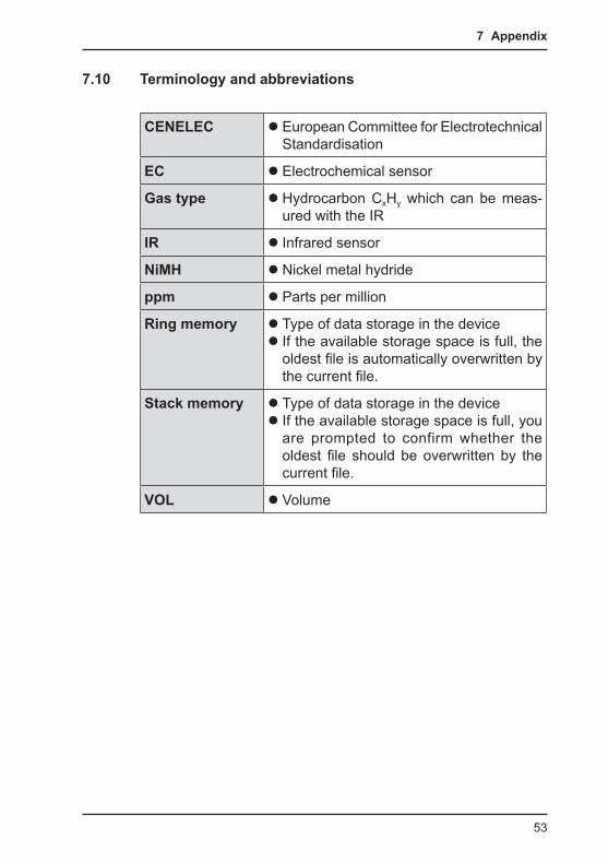
7.10 Terminology and abbreviations
CENELEC z European Committee for Electrotechnical Standardisation
EC z Electrochemical sensor
Gas type z Hydrocarbon CxHy which can be meas-ured with the IR
IR z Infrared sensor
NiMH z Nickel metal hydride
ppm z Parts per million
Ring memory z Type of data storage in the device z If the available storage space is full, the oldest file is automatically overwritten by the current file.
Stack memory z Type of data storage in the device z If the available storage space is full, you are prompted to confirm whether the oldest file should be overwritten by the current file.
VOL z Volume
54
7 Appendix
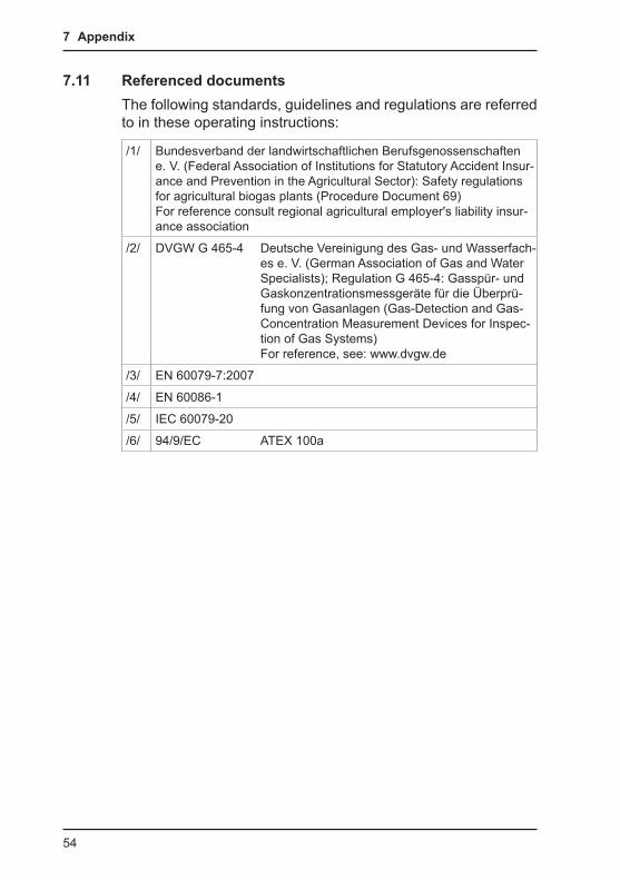
7.11 Referenced documentsThe following standards, guidelines and regulations are referred to in these operating instructions:
/1/ Bundesverband der landwirtschaftlichen Berufsgenossenschaften e. V. (Federal Association of Institutions for Statutory Accident Insur-ance and Prevention in the Agricultural Sector): Safety regulations for agricultural biogas plants (Procedure Document 69) For reference consult regional agricultural employer's liability insur-ance association
/2/ DVGW G 465-4 Deutsche Vereinigung des Gas- und Wasserfach-es e. V. (German Association of Gas and Water Specialists); Regulation G 465-4: Gasspür- und Gaskonzentrationsmessgeräte für die Überprü-fung von Gasanlagen (Gas-Detection and Gas-Concentration Measurement Devices for Inspec-tion of Gas Systems) For reference, see: www.dvgw.de
/3/ EN 60079-7:2007
/4/ EN 60086-1
/5/ IEC 60079-20
/6/ 94/9/EC ATEX 100a
55
8 Index
8 IndexAAccessories: 44Adjustment 17, 33
C02 17CH4 17Of oxygen 35Performing 33Preparation 33Scope 33Sensitivity 34Zero point 34
Adjustment menu 17Autostart 18
BBattery 18
Replacing 23Requirements 20Setting the type 18
Battery alarm 22
CCarbon dioxide filter 34Cleaning 43Clearing 19Comment 13
DDate 19Device
Switching off 7Switching on 7
Device info 14Device inspection 14, 19, 24
Accessing 26Concluding 27Documentation 24Frequency 24Integrated 25Limits 40Performing 26Scope 24Sequence 26Switching on 25
Display 18
Display contrast 18Display illumination 18Disposal 52
EElectrostatic charge 43Error message 38Explosion protection 6
FFactory settings 19Faults 38Filter 30Fine dust filter 30Function key 7
GGas measuring 12General Status 29
HHousing 29
IIdentification plate 43Indication accuracy
With fresh air 31With test gas 31
Inspection OK 17Interval 19
JJog dial 7
KKeys 7
LLanguage 19
56
8 Index
MMain menu see MenuMaintenance 24Measurement
Save 12Starting 12Stopping 12
Measuring mode 10, 11Menu structure 11
Memory 19, 40Memory mode 19Menu 8, 11
Exiting 8Opening 11Selecting 8
Menu itemExiting 8Selecting 8
Menu structure 11, 16
OOperation 7Oxygen 35
PPIN code 15, 18Power supply 20Probe 29Protocols 13Pump 30
RRechargeable battery 21
Charging 21Replacing 23Requirements 21Self-discharge 21Servicing 22Setting the type 18
Ring memory 19
SSensitivity
Adjusting 34, 36Sensors 5, 41
Electrochemical 5, 42
Infrared~ 5, 41Installation date 14
Service interval 18Servicing 37Settings 10, 12, 15
Menu structure 16Opening 15
Signals 29Audible 5Visual 5
Stack memory 19System 18
TTest gas
Changing 32Time 19
UUse
Intended 3
ZZero point 11
Adjusting 34, 35

Hermann Sewerin GmbHRobert-Bosch-Straße 3 · 33334 Gütersloh · Germany
Telefon +49 5241 934-0 · Telefax +49 5241 934-444www.sewerin.com · [email protected] 01
.08.
2011
– 1
0583
2 –
en