Embed Size (px)
Citation preview

PIPELINE INSPECTION COMPANY LTD.
OPERATING INSTRUCTIONS
PT-107, 275, and 750, PTR, PTS, PTSB, PTSI and PTSM
Pig Tracking Systems Portable and
“On Pipe” Systems

Table of Contents
Pipeline Pig Tracking Systems . . . . . . . . . . . . . .3-4 Electromagnetic Transmitters . . . . . . . . . . . . . . .5-6 Transmitter Specifications . . . . . . . . . . . . . . . . .7-8 Replacing Batteries . . . . . . . . . . . . . . . . . . . . .8-10 Pig Tracker Receiver (PTR) . . . . . . . . . . . . . . . . . .11 PTR Specifications . . . . . . . . . . . . . . . . . . . . . . . .12 Setup and Free Air Test for the PTR . . . . . . . . . . .13 Launching and Tracking . . . . . . . . . . . . . . . . . . .14 Pinpointing a Stuck Pig . . . . . . . . . . . . . . . . . . . .15 Mounting Plate Instructions . . . . . . . . . . . . . . . .16 PT-275 and PT-750 Towing Instructions . . . . . . . .17 Pig Tracker Sensor (PTS) . . . . . . . . . . . . . . . . . . .18 PTS General Information . . . . . . . . . . . . . . . . . .19 Individual Modules . . . . . . . . . . . . . . . . . . . . . . .20 Specifications . . . . . . . . . . . . . . . . . . . . . . . . . . .21 Mounting Hardware PT-275 . . . . . . . . . . . . . . . .22 Mounting Hardware PT-750 . . . . . . . . . . . . . . . .23
2

Pipeline Pig Tracking Systems
Pipeline Inspection Company Ltd. manufactures a complete line of portable and “On-Pipe” pig tracking and locating systems. Pig Tracking refers to monitoring the passage of a pig as it moves past prescribed and monitored points along the pipeline. Pig Locating refers to pinpointing a pig that has become stuck or lost in a given pipeline or pipe manifold system on land or at sea.
Unfortunately, carbon steel pipe acts as an ideal electromagnetic shield, which limits the possible methods of transmitting a signal through the pipe wall to a sensor. The common methods used to sense the passage of a pig or attempt to locate it are: mechanical; radioactive; acoustic; magnetic; and electromagnetic.
Mechanical systems have several drawbacks. They are invasive into the line, which makes them a potential environmental and safety hazard. They are subject to contamination by materials in the pipe, which can prevent them from operating correctly. They are also subject to mechanical wear and damage, which will prevent them from operating properly.
Radioactive systems have two main drawbacks. One of which, the radioactive nature of the transmitting device itself makes people extremely skittish in regards to using it. The second is that the transmit-ting distance is very limited which makes it primarily usable only when the “outside-the-pipe” sensor is directly attached to the pipe.
Acoustic systems generate an audible signal, which can be picked up by external sensors, but only when there is sufficient acoustic coupling between the transmitter and the wall of the pipe. This usually limits their use to lines filled with liquid, and as you might expect lines which do not operate in a high noise environment such as sub-sea lines.
Magnet equipped pigs operate well for tracking. They are not of any use in locating a stuck pig as it is practically impossible to locate them when they are not in motion. This is simply due to the physics of the type of signal generated.
3
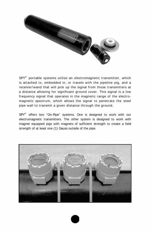
SPY® portable systems utilize an electromagnetic transmitter, which is attached to, embedded in, or travels with the pipeline pig, and a receiver/wand that will pick up the signal from those transmitters at a distance allowing for significant ground cover. This signal is a low frequency signal that operates in the magnetic range of the electro-magnetic spectrum, which allows the signal to penetrate the steel pipe wall to transmit a given distance through the ground.
SPY® offers two “On-Pipe” systems. One is designed to work with our electromagnetic transmitters. The other system is designed to work with magnet equipped pigs with magnets of sufficient strength to create a field strength of at least one (1) Gauss outside of the pipe.
4

Electromagnetic Transmitters
General Information
Pipeline Inspection Company, Ltd. transmitters pulse at approximately one pulse every second, which helps to identify this signal over spurious random noise that the receiver may pick up. This pulse can easily be detected by using our pig tracker receiver (PTR) and by many other electromagnetic receivers on the market.
The PT-107 is designed to be mounted in a Poly foam cavity pig. The PT-275 and PT-750 can be placed in a cavity pig, mounted to a mandrel pig, or towed behind another pig for ease of use.
These transmitters are “O” ring sealed (water tight) and capable of working in high-pressure environments (see page 7). Their main bodies are constructed of rugged carbon steel. Care should be exercised when exposing them to harsh chemicals. Check with the factory for chemical compatibility.
Our electromagnetic transmitters utilize off the shelf batteries for easy inexpensive replacement capability. While these batteries provide ample life for the transmitters in service, it is prudent practice to use fresh batteries prior to each new use. Please note that you should check the expiration date on the batteries that you purchase as older batteries with reduced life might be sold at retail outlets.
Other than replacing the batteries or “O”rings, each transmitter is essentially maintenance free. Please note that if the transmitters are damaged by abrupt stops or by valve gates etc., they may require repair at the factory prior to re-use. Please inspect them after each use for obvious damage. This could result in significantly lower repair charges.
5
NOTE :
6
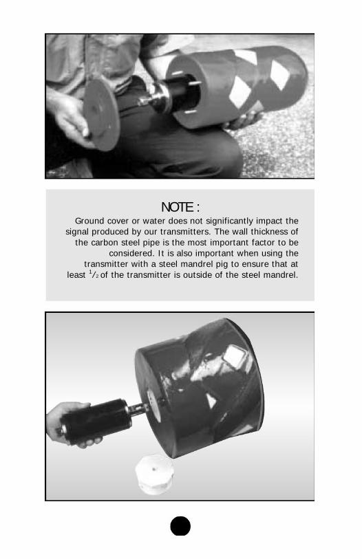
Ground cover or water does not significantly impact the signal produced by our transmitters. The wall thickness of
the carbon steel pipe is the most important factor to be considered. It is also important when using the
transmitter with a steel mandrel pig to ensure that at least 1⁄2 of the transmitter is outside of the steel mandrel.

Transmitter Specifications
Model PT-107 Pipe Sizes: 2”(50.8mm) Sch 80 to 8”(203.2mm)
Pressure Rating: 1,000 PSIG (6,894 kPa)
Bends: 2” (50.8mm) 5D*
3”(76.2mm) - 8”(203.2mm) 3D*
Battery: (1) 3 Volt Lithium Cell
Type: Cr 123 A
Battery Life: 60 hours
Transmission Distance “Free Air”: 20-25 ft. (6.1-7.6m)
Max Ground Cover: 8ft. (2.4m)
Length: 6 5/16” (160.3mm)
Diameter: 1 1/4” (31.75mm)
Minimum Mounting Cavity Hole: 1.5” (38.1mm)
Temperature Range: -20°F (-29°C) to 180°F (82°C)
Weight: 2.5 lbs. (1.13kg)
Model PT-275 Pipe Sizes: 6”(152.4mm) and up
Pressure Rating: 2,000 PSIG (13,789 kPa)
Bends: 3D*
Batteries: (4) 1.5 Volt Alkaline
Type: AA
Battery Life: 200 hours
Transmission Distance “Free Air”: 60-75 ft. (18.3-22.9m)
Max Ground Cover: 15ft. (4.6m)
Length: 7.5” (190.5mm)
Diameter: 3” (76.2mm)
Minimum Mounting Cavity Hole: 3.25” (82.5mm)
Temperature Range: -20°F (-29°C) to 180°F (82°C)
Weight: 6.5 lbs. (2.95 kg)
7

Model PT-750 Pipe Sizes: 12” (304.8mm) and up
Pressure Rating: 3,000 PSIG (20,684 kPa)
Bends: 3D*
Batteries: (8) 1.5 Volt Alkaline
Type: C
Battery Life: 500 hours
Transmission Distance “Free Air”: 100 ft. (30.48m)
Max Ground Cover: 25-30 ft. (7.6-9 1m)
Length: 13 7/8” (352.4mm)
Diameter: 3 9/16” (90.5mm)
Minimum Mounting Cavity Hole: 3.8” (96.5mm)
Temperature Range: -20°F (-29°C) to 180°F (82°C)
Weight: 13.5 lbs. (6.12kg)
• When calculating pipe bends, please reference the pig manufacturer and take into consideration the method of attachment (i.e., cavity mounted, bracket mounted, towed etc.).
Replacing Batteries
CAUTION! In each case, once batteries have been installed
and the end cap attached, the transmitter is “ON” and transmitting.
Battery life is therefore depleting so you should
8

only install them right before use.

PT-107 ( (1) -3v Lithium ) Unscrew and remove the removable end cap by turning the cap counter-clockwise. Insert the 3V lithium battery with the negative terminal toward the spring inside the transmit-ter body and the positive button toward the removable end cap. If in doubt, observe the red decal on the outside of the transmitter body for proper orientation. Replace the end cap and tighten securely.
PT-275 ( (4) 1.5v AA-Alkaline) Locate the removable end cap of the PT-275. It does not have multiple screw penetrations. Unscrew the removable end cap by turning it count- er-clockwise. remove the other end cap, as it wil l result in damage to the transmitter. Before installing the batteries, look into each of the battery tubes to be sure the spring contacts are clean and free of
any foreign material. This is also a good time to inspect the “O” ring primary and secondary seals to ensure that they are in place, clean and without cuts or abrasions. If in doubt replace these “O” rings to ensure against media penetration that could result in significant repairs being required for the transmitter. If the “O” ring needs to be replaced or is overly snug, a thin coat of petroleum jelly will help. Install the batteries with the positive and negative ends facing towards the removable cap as indicated by the sticker immediately viewable upon removing the cap. One side (2 batteries) is to be loaded positive end out and the other side negative end out. Screw on the end cap and tighten securely with a wrench. If the batteries are not properly installed no damage will be done; however the transmitter will not operate.
9

PT-750 ( (8) 1.5v “C” Alkaline Cell) Locate the removable end cap of the PT-750. It does not have multiple screw penetrat ions. Unsc rew the removable end cap by turning it count- er-c lockwise. Do not a t tempt to remove the other end cap, as it will result in damage to the transmitter. When the end cap is removed, you will see the black battery holder assembly. Remove this. It will come out easily.
You will see four (4) individual battery holders on each side. Make sure prior to putting the batteries in that all contacts are clean. Place the negative ends of the batteries into each holder towards the spring. Press down and push back on the positive end until it snaps into place. If the batteries are not properly installed, a protection circuit will pre-vent the transmitter from operating. This is also a good time to inspect the “O” ring seal to ensure that it is in place, clean and without cuts or abrasions. If in doubt replace the “O” ring to ensure against media penetration that could result in significant repairs being required for the transmitter. If the “O” ring needs to be replaced or is overly snug, a thin coat of petroleum jelly will help. Replace the battery holder assembly by placing the end with the springs back into the transmitter body first and with the spine holding the individual battery holders together opposite the other internal assembly in the transmitter tube. Replace the removable cap and secure it snugly with a wrench.
CAUTION! Never Attempt to Remove the White Piece Inside
The Transmitter as it will Result in Significant Damage to the Transmitter.
It is prudent to use new batteries with each new job.
1 0
Pig Tracker Receiver (PTR)
General Information
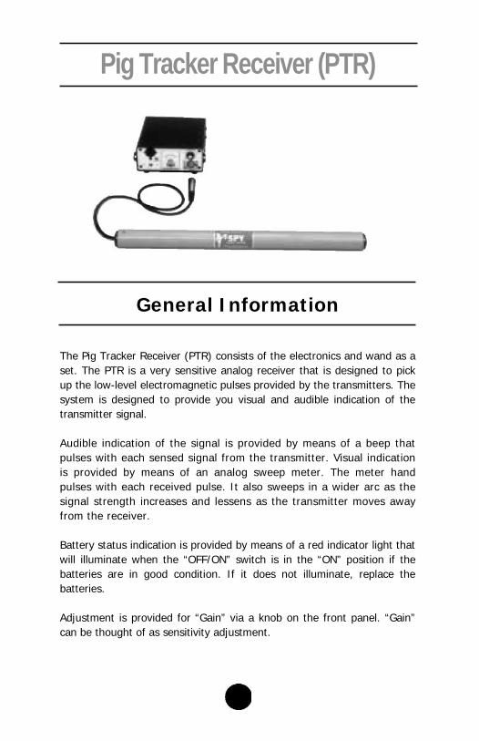
The Pig Tracker Receiver (PTR) consists of the electronics and wand as a set. The PTR is a very sensitive analog receiver that is designed to pick up the low-level electromagnetic pulses provided by the transmitters. The system is designed to provide you visual and audible indication of the transmitter signal.
Audible indication of the signal is provided by means of a beep that pulses with each sensed signal from the transmitter. Visual indication is provided by means of an analog sweep meter. The meter hand pulses with each received pulse. It also sweeps in a wider arc as the signal strength increases and lessens as the transmitter moves away from the receiver.
Battery status indication is provided by means of a red indicator light that will illuminate when the “OFF/ON” switch is in the “ON” position if the batteries are in good condition. If it does not illuminate, replace the batteries.
Adjustment is provided for “Gain” via a knob on the front panel. “Gain” can be thought of as sensitivity adjustment.
11
The PTR also provides for a remote signal, which can be sent to a separate device to allow for remote registering of transmitter pulses.
The sensitivity that is essential to pick up these low-level electromagnetic signals, is also a weakness in that it subjects the unit to potential false sig-nal trips. The more gain you can set without false triggering, the better.
PTR Specifications
Size:
Wand: 22” (559mm) X 1.6” (41mm) measured from wand
tip to end of strain relief for cable.
PTR: 6.4” (163mm) X 3.0” (76mm) X 8.4” (213mm)
measured from side to side, bottom of feet to top
of unit, and bottom of rear feet to forward tip of
knob.
Weight: Wand: 3.0 lbs. (1.36kg)
PTR: 3.2 lbs. (1.45kg)
Battery: (2) 9 Volt Alkaline
Battery Life: 50 Hours
Interconnect: Quick Release Audio Connector
1 2

Setup and Free Air Test for the PTR
If desired, attach the supplied strap to the two “D” rings on each side of the receiver to allow the receiver to be hung over the shoulder for ease of carrying.
Plug the Wand into the lower right side female audio receptacle on the front of the PTR. To later release the wand, press the tab with the word “PUSH” down until the connector is released.
Place the wand parallel to the transmitter.
To test for proper operation of the transmitter and receiver, begin by placing the transmitter on the ground approximately 10 – 15 ft (3.05 m – 4.6 m) from the wand. With the receiver switched on, turn the wand until it parallels the transmitter and be sure that it is horizontal. Increase the receiver gain until you hear the transmitter signal beep while verifying that you see the visual indicator moving with the pulses. Begin moving away from the transmitter laterally while keeping the wand steady, horizontal and parallel to the transmitter. The analog meter movement will begin to decrease with distance. Begin to increase the gain slowly as you walk away, ensuring that you continue to receive signal from the transmitter. Continue walking away as you turn the gain slowly up to maximum (10). Continue walking away until you loose the signal. This point represents the maximum free air trans-mit distance for this transmitter.
NOTE : As you turn the gain above 5, you will begin to notice
more false signaling created by movement of the wand. You should also note that due to the nature of the type of
signal the receiver senses, items such as, keys, pocket knives, tools, large metal belt buckles, or other metallic
items can cause disturbances in the earth’s electromagnetic field, and create false signals.
Other possible sources of false signals are electronic wristwatches, electronic vehicle ignition systems, and two
way portable radios.
1 3
Before Launching the Transmitter in an Actual Pigging Situation
A short period of working with the units in the shop prior to using the equipment in the field is highly recommended.
After the batteries have been installed in the transmitter and before the pig has been launched, turn the transmitter on and verify that you can pick up the transmitter. Move away approximately 5 to 10 ft (1.5 m to 3.04 m). Place the wand parallel to the pipe and turn the gain to 5 or 6. Verify that you still receive the pulse. Again, note that you should not set the “Gain” higher than necessary in order to pick up the signal as that will make the possibility of false triggering much more likely. Conversely, if the “Gain” is set too low, you may not be able to detect passage of the pig. If you cannot receive the transmit-ter signal by adjusting the gain, replace the batteries in the transmitter and receiver.
Launching and Tracking
Prior to actual launch, and after the above described testing, place the wand parallel and directly above the pipe on the ground, some distance down from the launcher. Set the receiver gain to approxi-mately 5 to 6. This will provide a positive indication that the pig has actually left the launcher when the launch process begins.
Repeat this process at prescribed intervals along the pig run and monitor the pig movement past these checkpoints to verify the pig’s progress.
By using two receivers you can “leapfrog” one over the other to track the passage. This process is highly recommended. Minimize the distance between the “leapfrog” positions in order to minimize the possible distance that will have to be walked to locate a stuck pig.
1 4
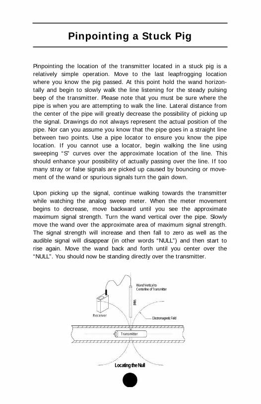
Pinpointing a Stuck Pig
Pinpointing the location of the transmitter located in a stuck pig is a relatively simple operation. Move to the last leapfrogging location where you know the pig passed. At this point hold the wand horizon-tally and begin to slowly walk the line listening for the steady pulsing beep of the transmitter. Please note that you must be sure where the pipe is when you are attempting to walk the line. Lateral distance from the center of the pipe will greatly decrease the possibility of picking up the signal. Drawings do not always represent the actual position of the pipe. Nor can you assume you know that the pipe goes in a straight line between two points. Use a pipe locator to ensure you know the pipe location. If you cannot use a locator, begin walking the line using sweeping “S” curves over the approximate location of the line. This should enhance your possibility of actually passing over the line. If too many stray or false signals are picked up caused by bouncing or move-ment of the wand or spurious signals turn the gain down.
Upon picking up the signal, continue walking towards the transmitter while watching the analog sweep meter. When the meter movement begins to decrease, move backward until you see the approximate maximum signal strength. Turn the wand vertical over the pipe. Slowly move the wand over the approximate area of maximum signal strength. The signal strength will increase and then fall to zero as well as the audible signal will disappear (in other words “NULL”) and then start to rise again. Move the wand back and forth until you center over the “NULL”. You should now be standing directly over the transmitter.
Wand Vertical to Centerline of Transmitter
Wand
Electromagnetic Field Receiver
Transmitter
Locating the Null
1 5

Transmitter Mounting Plate Instructions
PT-215 and PT-150 If the PT-275 or PT-750 transmitter is to be used on a hollow steel bod-ied mandrel pig, a mounting system will be provided to mount the transmitter to the rear of the pig. The pig body cavity must have a minimum interior diameter of 3.25” for a PT-275 or 3.8” for a PT-750. A mounting cup and spacer can be provided for use with the PT-275 and a set of mounting brackets can be supplied for the PT-750 upon request.
PT-275 Mounting Cup
PT-750 Mounting Flange
See pages 22 & 23 for larger drawings
1 6

PT-215 and PT-150 Towing Instructions If the PT-275 or PT-750 transmitter cannot be mounted on the body of the pig or enclosed in the cavity of a polyurethane pig, then it can be towed behind the pig. The front “towing eye” can be attached by means of chain to the rear of the “working” pig. Spacers or wear rings should be attached to the front and rear mounting bolts to keep the transmitter in the center of the pipe and to minimize damage. Note to be sure that the towing eye must be attached to the non-removable cap end opposite the battery end to ensure that it does not come loose during transit.
Spacer
PT-275
or PT-750
Spacer
P ig
1 7

Pig Tracker Sensor (PTS)
When the need for noting the passage of a pig becomes a little less temporary, (e.g.; manpower or distance prevents leap frogging) then SPY® offers a line of stationary Pig Tracking Sensors (PTS). We offer the standard PTS for use with electromagnetic transmitters and our model PTS-M for use with magnet equipped pigs. The units come in a modular format which allows customers to pay only for what they need.
The PTS systems require NO HOLE to be drilled in the pipe. This non-invasive system allows for lower installation costs and significantly reduces the overall cost of the monitoring point. It also offers safer monitoring. This feature also makes the PTS more desirable than invasive systems from a pollution prevention standpoint.
The PTS systems must be mounted directly onto the pipe in order to pick up the signal of the transmitter or magnet. Care should be taken to allow sufficient distance between the sensor and the launcher/ receiver so that the pig can travel completely past the sensor.
NOTE : The PTS is a “passage” indicator,
not a “presence” indicator.
1 8

Mounting can be permanent or temporary and can be accomplished by using pipe straps or clamps. Units can be installed along the line as often as is needed.
The systems are provided in explosion-proof Class I, Division 1, Groups B, C, & D certified enclosures. The enclosures come complete with an “O” ring seal, which makes the housing NEMA 4X/7. Three quarter inch hubs are provided on each enclosure for conduit connection into your SCADA or recording system. When supplied by the factory as an assembly, proper explosion proof fittings are used and manufacturer-specified procedures are followed to connect the units in order to main-tain their rating. Make sure that you follow proper wiring and conduit procedures as specified by the appropriate authority for wiring in haz-ardous areas if you wish to connect your monitoring systems to the PTS system.
General Information
Wire the power input and signal output as indicated below. Attach the power-input wires (when using 120 VAC) as follows.
A.C. IN HOT COMMON GND
DRY CONTACTS
Black Wire White Wire Green Wire
Attach the output dry contacts.
When field wiring for battery power, attach the battery wiring to jumper J2 on the Power distribution board.
Connector J3 is the connector for connecting the PTSI to the PTS unit to receiver power and signal.
1 9

Individual Modules
PTS Sensor The PTS Sensor is the key module to all config-urations of the PTS system. The Sensor Unit can be powered using 120 Volts AC input or by ±3VDC input from the PTSB module. The sen-sor picks up the presence of the Pig Tracker Transmitter signal and then activates a set of normally open dry contacts with a maximum rating of 1A @ 250 Volts DC. These contacts will remain engaged as long as the signal is present. They will open within two seconds of the absence of the signal.
PTSB Battery Power Module The battery module can supply ±3VDC Volts DC for powering the Sensor and 18 volts DC for powering the PTSI indicator module. This module can also be configured to supply backup power for a 120-Volt AC powered version of the PTS Sensor.
PTSI Indicator Module The PTSI indicator is powered by the PTSB module or by the 120 Volt AC being supplied to an AC powered PTS module. The indicator for noting pig passage is a 2 inch orange disc. This disc is orange on one side and black on the other. When the PTS notes a Pig Transmitter signal by closing the contacts in the PTS, that actuates the indicator to flip from Black to Orange. The indicator is visible by means of a viewing window in the cover of the unit. This unit must be reset after each passage of a pig by the means of an external magnetic button.
2 0

PTS-M The PTS-M is different from the PTS in that it is designed to pick up the passage of a pig equipped with a magnet instead of a transmit-ter. The magnet must produce a magnetic field strength or Gauss level of at least one (1) Gauss outside of the pipe for the PTS-M to see the magnet. It is also best if the pig is moving at least one foot per second as it passes the PTS-M. The installation must also allow the pig to completely pass by the position of the PTS-M in order for it to function appropriately. The PTS-M operates the same as the PTS electromagnetic sensor in every other regard.
PTS-M Transit Speed: minimum of 1 fps. Minimum of One Gauss Outside of the Pipe.
Specifications PTS•PTSI•PTSB•PTS-M
Enclosure: Enclosure Class I, Division 1, Groups B, C& D Blind modules for PTS/PTSB and With Window for PTSI
Power Input Either 120 Volts AC or ±3VDC Volts DC (Sensor Module) and 18 Volts DC for Indicator. Other types of power supply inputs can be used, but must be specified on order entry to allow for modifications to be made to the modules in house at Pipeline Inspection Company, Ltd.
Output – PTS/PTS-M Normally Open non-latching Dry Contacts rated at 1A at 250 Volts AC
Output – PTSI Visual indication via 2 inch Orange Disk, manual reset required.
Output – PTSB ±3 Volts DC – provided by (4) 1.5 Volt AA alkaline batteries – to power PTS
18 Volts DC- provided by (2) 9 Volt alkaline batteries – to power PTSI
2 1

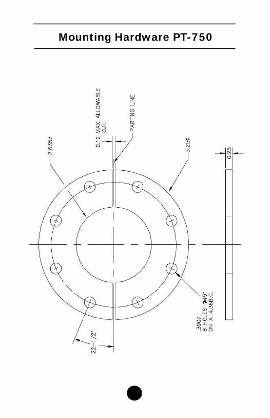
Mounting Hardware PT-275
22
Mounting Hardware PT-750
23

Pipeline Inspection Co., Ltd. Shipping Address:
1919 Antoine Houston, Texas 77055
www.picltd.com
Tel: 713/681-5837 Fax: 713/681-4838
E-mail: [email protected]
08.22.12