Embed Size (px)
Citation preview
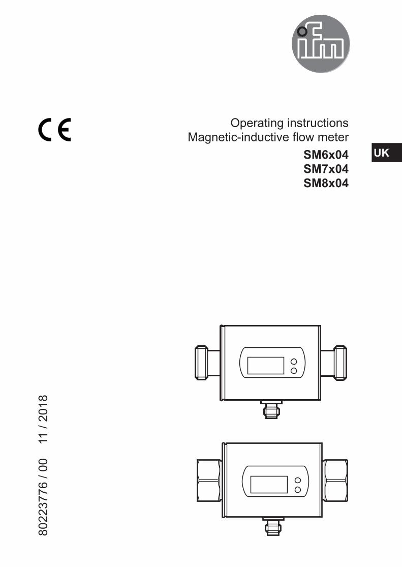
Operating instructions Magnetic-inductive flow meter
SM6x04 SM7x04 SM8x04
8022
3776
/ 00
1
1 / 2
018
UK

2
Contents1 Preliminary note ���������������������������������������������������������������������������������������������������32 Safety instructions �����������������������������������������������������������������������������������������������33 Functions and features ����������������������������������������������������������������������������������������44 Function ���������������������������������������������������������������������������������������������������������������5
4�1 Processing of the measured signals ��������������������������������������������������������������54�2 Direction of flow ���������������������������������������������������������������������������������������������54�3 Analogue function ������������������������������������������������������������������������������������������64�4 Measured value damping (dAP) ��������������������������������������������������������������������7
5 Mounting ��������������������������������������������������������������������������������������������������������������85�1 Recommended installation position ���������������������������������������������������������������85�2 Not recommended installation position ����������������������������������������������������������95�3 Grounding ����������������������������������������������������������������������������������������������������105�4 Installation in pipes �������������������������������������������������������������������������������������� 11
6 Electrical connection ������������������������������������������������������������������������������������������127 Operating and display elements ������������������������������������������������������������������������138 Menu ������������������������������������������������������������������������������������������������������������������149 Set-up ����������������������������������������������������������������������������������������������������������������1610 Parameter setting ��������������������������������������������������������������������������������������������16
10�1 Parameter setting in general ���������������������������������������������������������������������1710�1�1 Change to the menu "Extended functions" ���������������������������������������1710�1�2 Locking / Unlocking ��������������������������������������������������������������������������1710�1�3 Timeout ���������������������������������������������������������������������������������������������18
10�2 Scaling of the analogue value for temperature (OUT1) �����������������������������1810�3 Scaling of the analogue value for volumetric flow (OUT2) ������������������������1810�4 User settings (optional) ������������������������������������������������������������������������������18
10�4�1 Determine the standard unit of measurement for volumetric flow ����1810�4�2 Determine the standard unit of measurement for temperature ���������1810�4�3 Standard display �������������������������������������������������������������������������������1810�4�4 Measured value damping �����������������������������������������������������������������1810�4�5 Error behaviour of the outputs ����������������������������������������������������������19
10�5 Service functions ���������������������������������������������������������������������������������������1910�5�1 Read min/max values �����������������������������������������������������������������������19
3
UK
1 Preliminary note► Instructions> Reaction, result
[…] Designation of keys, buttons or indications→ Cross-reference
Important note Non-compliance may result in malfunction or interference�Information Supplementary note�
CAUTION Warning of personal injury� Slight reversible injuries may result�
2 Safety instructions• The device described is a subcomponent for integration into a system�
- The manufacturer of the system is responsible for the safety of the system� - The system manufacturer undertakes to perform a risk assessment and to create a documentation in accordance with legal and normative requirements to be provided to the operator and user of the system� This documentation must contain all necessary information and safety instructions for the operator, the user and, if applicable, for any service personnel authorised by the manu-facturer of the system�
10�5�2 Restoring the factory settings �����������������������������������������������������������1911 Operation ���������������������������������������������������������������������������������������������������������19
11�1 Reading the process value ������������������������������������������������������������������������1911�2 Changing the process value display in the RUN mode������������������������������2011�3 Reading the set parameters �����������������������������������������������������������������������20
12 Troubleshooting �����������������������������������������������������������������������������������������������2113 Technical data ��������������������������������������������������������������������������������������������������2114 Factory setting ������������������������������������������������������������������������������������������������22

4
• Read this document before setting up the product and keep it during the entire service life�
• The product must be suitable for the corresponding applications and environ-mental conditions without any restrictions�
• Only use the product for its intended purpose (→ Functions and features).• Only use the product for permissible media (→ Technical data). • If the operating instructions or the technical data are not adhered to, personal
injury and/or damage to property may occur� • The manufacturer assumes no liability or warranty for any consequences
caused by tampering with the product or incorrect use by the operator�• Installation, electrical connection, set-up, operation and maintenance of the unit
must be carried out by qualified personnel authorised by the machine operator�• Protect units and cables against damage�
3 Functions and featuresThe unit monitors liquid media� It detects the 2 process categories volumetric flow and medium temperature� Pressure Equipment Directive (PED) The units comply with the Pressure Equipment Directive and are designed and manufactured for group 2 fluids in accordance with the sound engineering prac-tice� Use of group 1 fluids on request� Application areaConductive liquids with the following properties:• Conductivity: ≥ 20 µS/cm• Viscosity: < 70 mm2/s at 40 °C; < 70 cSt at 104 °F

5
UK
4 Function• The unit detects the flow based on the magnetic-inductive volumetric flow
measuring principle�• The unit also detects the medium temperature�• The unit displays the current process value�
4.1 Processing of the measured signalsThe unit generates 2 output signals according to the parameter settings:
OUT1: Parameter setting - Analogue signal for temperature → 10.2
OUT2: Parameter setting - Analogue signal for volumetric flow quantity → 10.3
4.2 Direction of flowIn addition to the flow velocity and the volumetric flow quantity, the unit also detects the direction of flow� An arrow with the text "flow direction" on the unit indicates the positive flow direction�
Flow... Process value display corresponds to the marked flow direction + (positive)
against the marked flow direction - (negative)
Only positive process values are processed for the signal output�
6
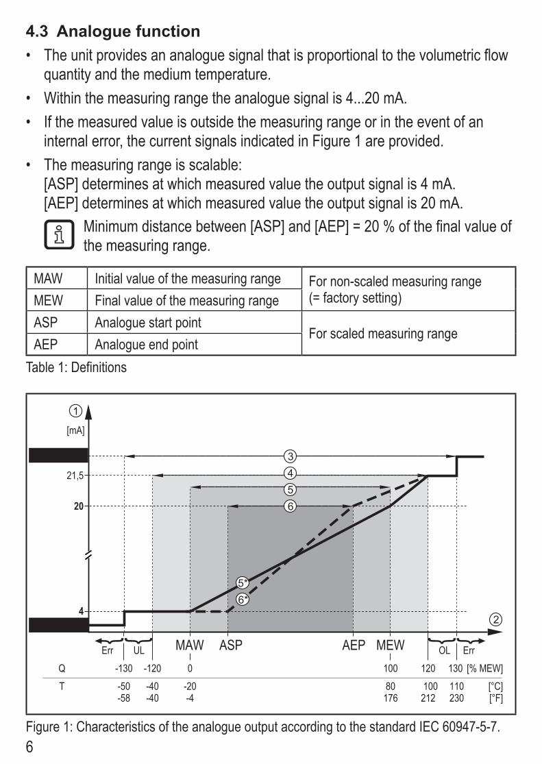
4.3 Analogue function• The unit provides an analogue signal that is proportional to the volumetric flow
quantity and the medium temperature� • Within the measuring range the analogue signal is 4���20 mA� • If the measured value is outside the measuring range or in the event of an
internal error, the current signals indicated in Figure 1 are provided�• The measuring range is scalable:
[ASP] determines at which measured value the output signal is 4 mA� [AEP] determines at which measured value the output signal is 20 mA�
Minimum distance between [ASP] and [AEP] = 20 % of the final value of the measuring range�
MAW Initial value of the measuring range For non-scaled measuring range (= factory setting)MEW Final value of the measuring range
ASP Analogue start pointFor scaled measuring range
AEP Analogue end pointTable 1: Definitions
MEWMAW AEPASPQ [% MEW]
[°C]T -20-40-50 80 100 110[°F]176-4-58 -40 212 230
1201000-120-130 130
43,5FOU=OFF
20
21,5
22
[mA]
FOU=On
1
2
54
6
5*6*
3
Err UL OL Err
Figure 1: Characteristics of the analogue output according to the standard IEC 60947-5-7�

7
UK
Q: Flow (a negative flow value means flow against the marked flow direction)T: TemperatureUL: Below the display rangeOL: Above the display rangeErr: The unit is in the error stateFOU=On: Default setting at which the analogue signal goes to the upper final value in
case of an error�FOU=OFF: Default setting at which the analogue signal goes to the lower final value in
case of an error�1 Analogue signal2 Measured value (flow or temperature)3 Detection zone4 Display range5 Measuring range
5* Analogue signal in the measuring range with factory setting
6 Scaled measuring range6* Analogue signal for scaled measuring
range
4.4 Measured value damping (dAP)The damping time allows to set after how many seconds the output signal has reached 63 % of the final value if the flow value changes suddenly� The set damp-ing time stabilises the outputs and the display� The signals [UL] and [OL] (→ 12)are defined under consideration of the damping time�
8
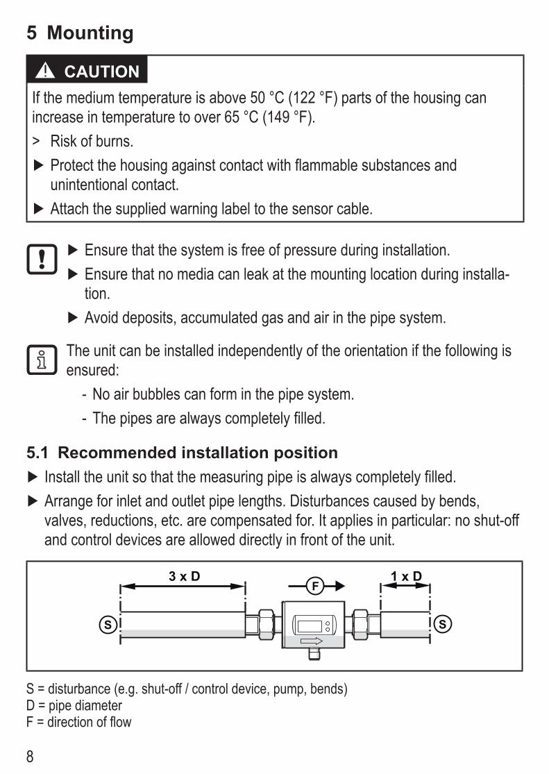
5 Mounting
CAUTION If the medium temperature is above 50 °C (122 °F) parts of the housing can increase in temperature to over 65 °C (149 °F)�
> Risk of burns� ► Protect the housing against contact with flammable substances and unintentional contact�
► Attach the supplied warning label to the sensor cable�
► Ensure that the system is free of pressure during installation� ► Ensure that no media can leak at the mounting location during installa-tion�
► Avoid deposits, accumulated gas and air in the pipe system�
The unit can be installed independently of the orientation if the following is ensured:
- No air bubbles can form in the pipe system� - The pipes are always completely filled�
5.1 Recommended installation position ► Install the unit so that the measuring pipe is always completely filled� ► Arrange for inlet and outlet pipe lengths� Disturbances caused by bends, valves, reductions, etc� are compensated for� It applies in particular: no shut-off and control devices are allowed directly in front of the unit�
3 x DF
S
1 x D
S
S = disturbance (e�g� shut-off / control device, pump, bends) D = pipe diameter F = direction of flow

9
UK
► Install in front of or in a rising pipe�
F F
5.2 Not recommended installation position ► Avoid the following installation positions:
F
F
Directly in front of a falling pipe� In a falling pipe�

10
F
F
Directly in front of the spout of the pipe� On the suction side of a pump�
F
At the highest point of the pipe system�
F = flow direction
5.3 GroundingIf installed in an ungrounded pipe system (e�g� plastic pipes), the unit must be grounded (functional earth)�
Ground brackets for the M12 connector are available as accessories → www.ifm.com.

11
UK
5.4 Installation in pipesThe units with a G thread can be installed in the pipes using adapters�Information about the available mounting accessories at www�ifm�com�A correct fit of the unit and ingress resistance of the connection are only ensured using ifm adapters�
A AD DC CB B
1� Grease the threads of the process connection, adapter and sensor� Use a
lubricating paste which is suitable and approved for the application� 2� Screw the adapter (B) into the pipe (A)� 3� Place the seals (C) and install the unit according to the marked flow direction� 4� Screw the adapter (B) with the threads (D) until it is hand-tight� 5� Tighten the two adapters in opposite direction (Tightening torque: 30 Nm)�
After installation air bubbles in the system can affect the measurement� ► Corrective measures: Rinse the system after installation for ventilation�
In case of horizontal installation: As a result of design requirements a small quantity of the medium always remains in the measuring channel after switching off the pump�

12
6 Electrical connectionThe unit must be connected by a qualified electrician�The national and international regulations for the installation of electrical equipment must be adhered to�Voltage supply according to EN 50178, SELV, PELV�
► Disconnect power� ► Connect the unit as follows:
43
2 1 BK: blackBN: brownBU: blueWH: white
BN
WH
BK
BU
4
1
3
2 OUT2
L+
L
OUT1
Colours to DIN EN 60947-5-2
Pin 1 L+Pin 3 L-Pin 4 (OUT1) Analogue signal for temperaturePin 2 (OUT2) Analogue signal for volumetric flow quantity

13
UK
7 Operating and display elements
1-8: Indicator LEDs• LEDs 1-6: Unit of the currently represented numerical value → 11.1 Reading the process
value• LED 7-8: not used
9: Alphanumeric display, 4 digits• Current volumetric flow quantity with setting [SELd] = FLOW• Current medium temperature with setting [SELd] = TEMP• Parameters and parameter values
10: [Mode/Enter] button• Change from the RUN mode to the main menu• Select parameters• Acknowledge the set parameter value
11: [Set] button• Change parameter values (hold button pressed)• Change of the display unit in the normal operating mode (RUN mode)

14
8 Menu
RUN
l/min °C / °Fm3/h
°C / °Fgpm gph
[Mode / Enter][Set]
Hi.F
Lo.F
Hi.T
Lo.T
FOU1
FOU2
dAP
diS
uni.F
uni.T
SELd
rES
EF
AEP2
ASP1
AEP1
ASP2
EF

15
UK
Parameters Explanation and setting options ASP1 Analogue start point for temperature on OUT1�
AEP1 Analogue end point for temperature on OUT1�
ASP2 Analogue start point for volumetric flow on OUT2�
AEP2 Analogue end point for volumetric flow on OUT2�
EF Extended functions: opening of the lower menu level�
Hi�F Maximum value memory for volumetric flow�
Hi�T Maximum value memory for temperature�
Lo�F Minimum value memory for volumetric flow�
Lo�T Minimum value memory for temperature�
FOU1 Behaviour of OUT1 in case of an internal fault: OU, On, OFF (→ 10.4.5)�
FOU2 Behaviour of OUT2 in case of an internal fault: OU, On, OFF (→ 10.4.5)�
dAP Measured value damping: damping constant in seconds�
diS Update rate and orientation of the display: d1���d3, rd1���rd3, OFF (→ 10.4.3)�
uni�F Standard unit of measurement for volumetric flow
uni�T Standard unit of measurement for temperature
SELd Standard measured variable of the display: FLOW (volumetric flow value), TEMP (medium temperature)�
rES Restoring the factory settings�

16
9 Set-upAfter power on and expiry of the power-on delay time of approx� 5 s the unit is in the RUN mode (= normal operating mode)� It carries out its measurement and evaluation functions and generates output signals according to the set parame-ters�During the power-on delay time the output signal is at 20 mA�
10 Parameter settingParameters can be set before installation or during operation�
If you change parameters during operation, this will influence the function� ► Ensure that there will be no malfunctions in your plant�
During parameter setting the unit remains in the operating mode� It continues to monitor with the existing parameter until the parameter setting has been complet-ed�
CAUTION If the medium temperature is above 50 °C (122 °F) parts of the housing can increase in temperature to over 65 °C (149 °F)� > Risk of burns�
► Do not touch the device with your hands� ► Use another object (e�g� a ballpoint pen) to carry out settings on the unit�
17
UK
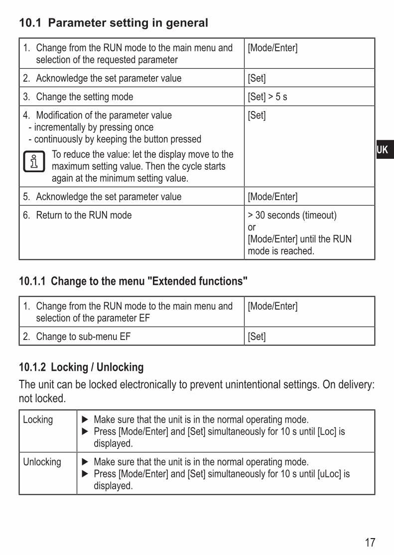
10.1 Parameter setting in general
1� Change from the RUN mode to the main menu and selection of the requested parameter
[Mode/Enter]
2� Acknowledge the set parameter value [Set]
3� Change the setting mode [Set] > 5 s
4� Modification of the parameter value - incrementally by pressing once - continuously by keeping the button pressed
To reduce the value: let the display move to the maximum setting value� Then the cycle starts again at the minimum setting value�
[Set]
5� Acknowledge the set parameter value [Mode/Enter]
6� Return to the RUN mode > 30 seconds (timeout) or[Mode/Enter] until the RUN mode is reached�
10.1.1 Change to the menu "Extended functions"
1� Change from the RUN mode to the main menu and selection of the parameter EF
[Mode/Enter]
2� Change to sub-menu EF [Set]
10.1.2 Locking / UnlockingThe unit can be locked electronically to prevent unintentional settings� On delivery: not locked�
Locking ► Make sure that the unit is in the normal operating mode� ► Press [Mode/Enter] and [Set] simultaneously for 10 s until [Loc] is displayed�
Unlocking ► Make sure that the unit is in the normal operating mode� ► Press [Mode/Enter] and [Set] simultaneously for 10 s until [uLoc] is displayed�

18
10.1.3 TimeoutIf no button is pressed for 30 s during parameter setting, the unit returns to the operating mode with unchanged values�
10.2 Scaling of the analogue value for temperature (OUT1)
► Select [ASP1] and set the value at which 4 mA is provided� ► Select [AEP1] and set the value at which 20 mA is provided�
10.3 Scaling of the analogue value for volumetric flow (OUT2)
► Select [ASP2] and set the value at which 4 mA is provided� ► Select [AEP2] and set the value at which 20 mA is provided�
10.4 User settings (optional)10.4.1 Determine the standard unit of measurement for volumetric flow
► Select [uni�F] and set the unit of measurement: Lmin, m3h, GPm or GPh�
10.4.2 Determine the standard unit of measurement for temperature ► Select [uni�T] and set the unit of measurement: °C or °F�
10.4.3 Standard display ► Select [SELd] and define the standard unit of measurement FLOW = display shows the current volumetric flow value in the standard unit of measurement� TEMP = display shows the current medium temperature in the standard unit of measurement�
► Select [diS] and set the update rate and orientation of the display: d1 = update of the measured values every 50 ms� d2 = update of the measured values every 200 ms� d3 = update of the measured values every 600 ms� rd1, rd2, rd3 = display like d1, d2, d3; rotated by 180� OFF = the display is switched off in the operating mode� The LEDs remain active even if the display is deactivated� Error messages are displayed even if the display is deactivated�
10.4.4 Measured value damping ► Select [dAP] and set the damping constant in seconds (τ value 63 %).
19
UK
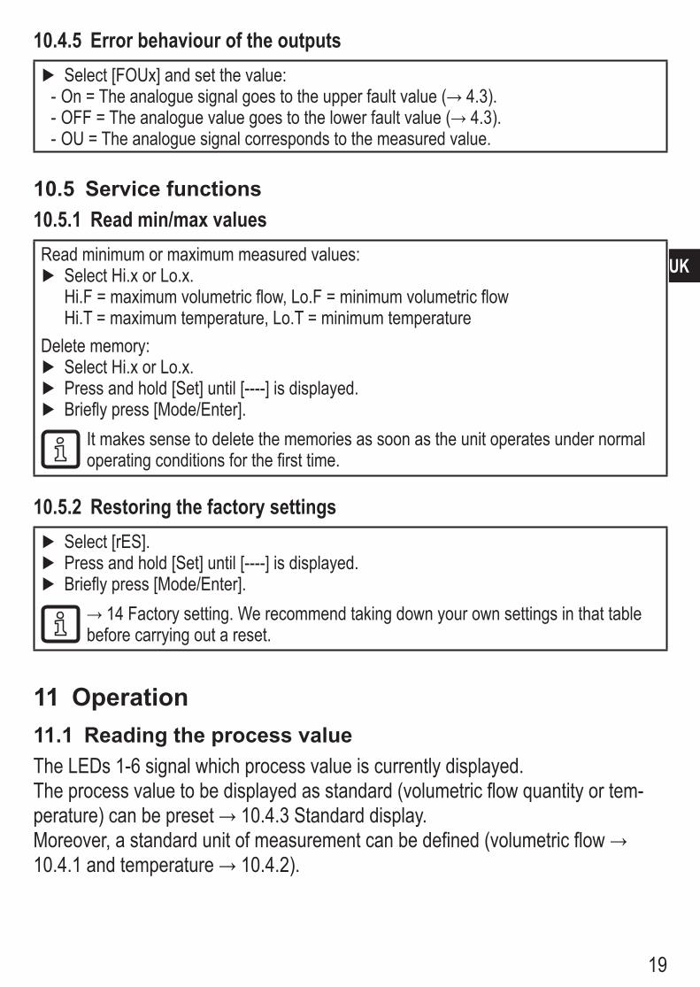
10.4.5 Error behaviour of the outputs ► Select [FOUx] and set the value: - On = The analogue signal goes to the upper fault value (→ 4.3)� - OFF = The analogue value goes to the lower fault value (→ 4.3)� - OU = The analogue signal corresponds to the measured value�
10.5 Service functions10.5.1 Read min/max valuesRead minimum or maximum measured values:
► Select Hi�x or Lo�x� Hi�F = maximum volumetric flow, Lo�F = minimum volumetric flow Hi�T = maximum temperature, Lo�T = minimum temperature
Delete memory: ► Select Hi�x or Lo�x� ► Press and hold [Set] until [----] is displayed� ► Briefly press [Mode/Enter]�
It makes sense to delete the memories as soon as the unit operates under normal operating conditions for the first time�
10.5.2 Restoring the factory settings ► Select [rES]� ► Press and hold [Set] until [----] is displayed� ► Briefly press [Mode/Enter]�
→ 14 Factory setting� We recommend taking down your own settings in that table before carrying out a reset�
11 Operation11.1 Reading the process valueThe LEDs 1-6 signal which process value is currently displayed�The process value to be displayed as standard (volumetric flow quantity or tem-perature) can be preset → 10.4.3 Standard display� Moreover, a standard unit of measurement can be defined (volumetric flow → 10�4�1 and temperature → 10.4.2)�
20
11.2 Changing the process value display in the RUN mode ► Briefly press [Set] in the RUN mode� Press the pushbutton to move to the next display unit�
> The unit displays the current measured value in the selected display unit for approx� 30 s, the corresponding indicator LED lights (→ 7)�
11.3 Reading the set parameters ► Briefly press [Mode/Enter] to scroll through the parameters� ► Briefly press [Set] when the requested parameter is displayed�
> The unit displays the corresponding parameter value� After about 15 s it returns to the RUN mode�
21
UK
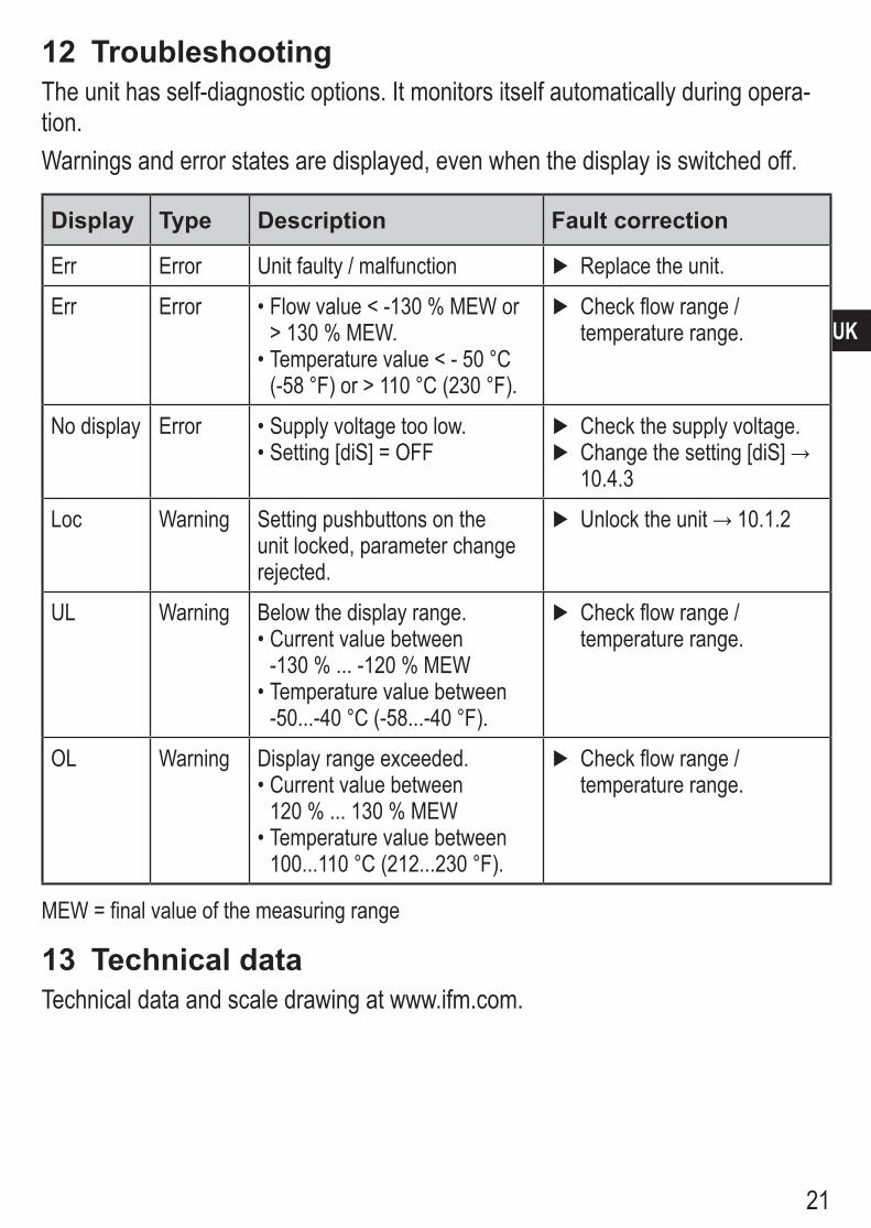
12 TroubleshootingThe unit has self-diagnostic options� It monitors itself automatically during opera-tion� Warnings and error states are displayed, even when the display is switched off�
Display Type Description Fault correction
Err Error Unit faulty / malfunction ► Replace the unit�
Err Error • Flow value < -130 % MEW or > 130 % MEW�
• Temperature value < - 50 °C (-58 °F) or > 110 °C (230 °F)�
► Check flow range / temperature range�
No display Error • Supply voltage too low�• Setting [diS] = OFF
► Check the supply voltage� ► Change the setting [diS] → 10�4�3
Loc Warning Setting pushbuttons on the unit locked, parameter change rejected�
► Unlock the unit → 10.1.2
UL Warning Below the display range�• Current value between
-130 % ��� -120 % MEW• Temperature value between
-50���-40 °C (-58���-40 °F)�
► Check flow range / temperature range�
OL Warning Display range exceeded� • Current value between
120 % ��� 130 % MEW• Temperature value between
100���110 °C (212���230 °F)�
► Check flow range / temperature range�
MEW = final value of the measuring range
13 Technical dataTechnical data and scale drawing at www�ifm�com�
22
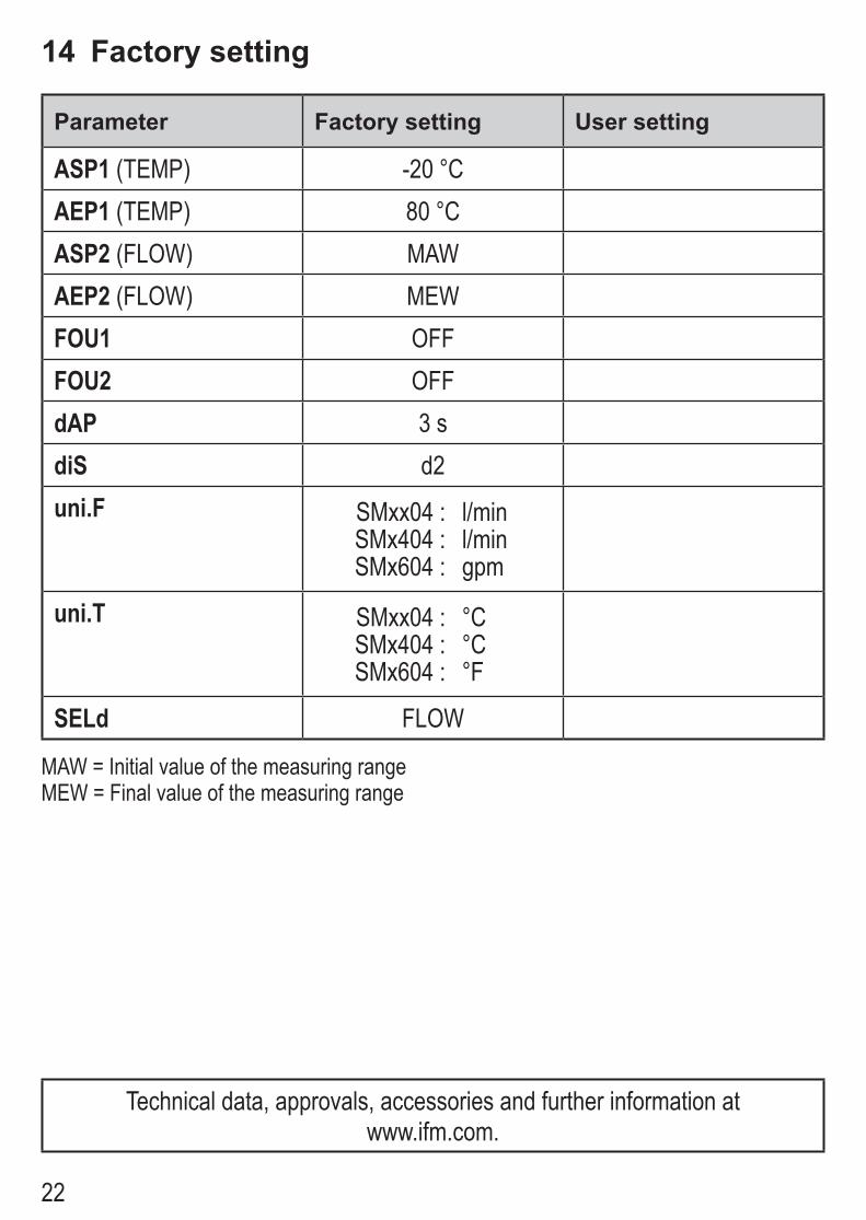
14 Factory setting
Parameter Factory setting User setting
ASP1 (TEMP) -20 °CAEP1 (TEMP) 80 °CASP2 (FLOW) MAWAEP2 (FLOW) MEWFOU1 OFFFOU2 OFFdAP 3 sdiS d2uni.F SMxx04 : l/min
SMx404 : l/minSMx604 : gpm
uni.T SMxx04 : °CSMx404 : °CSMx604 : °F
SELd FLOW
MAW = Initial value of the measuring rangeMEW = Final value of the measuring range
Technical data, approvals, accessories and further information at www�ifm�com�