Embed Size (px)
Citation preview

Operation Instructions
MBE35_50 OPERATION MANUAL 2005_10 - 1 -
Operating Instructions
MAGSTOP Traffic Barrier MBE35/50
Version 2005_10
Operation Instructions
MBE35_50 OPERATION MANUAL 2005_10 2
TABLE OF CONTENTS
1.0 SAFETY ...........................................................................................................................................................4 1.1 SAFETY SYMBOLS USED IN THIS HANDBOOK................................................................................................................................ 4 1.2 GENERAL SAFETY INFORMATION.................................................................................................................................................. 5 1.3 INTENDED USE.............................................................................................................................................................................. 5 1.4 WARNING AND SAFETY SIGNAGE ................................................................................................................................................. 5 1.5 SAFETY REQUIREMENTS.............................................................................................................................................................. 6 1.6 OPERATIONAL SAFETY ................................................................................................................................................................. 7 1.7 TECHNICAL DEVELOPMENTS ........................................................................................................................................................ 8 1.8 WARRANTY................................................................................................................................................................................... 8
2.0 INSTALLATION ...................................................................................................................................................8
2.0 INSTALLATION ...................................................................................................................................................9 2.1 GUIDELINES FOR FOUNDATION .................................................................................................................................................... 9 2.1 MOUNTING THE HOUSING TO THE GROUND ............................................................................................................................... 10
3.0 OPERATING THE MBE* BARRIER GATE..........................................................................................................13
4.0 CONTROLLER...................................................................................................................................................14 4.1 GENERAL .................................................................................................................................................................................... 14 4.2 CONTROLLER INPUTS................................................................................................................................................................. 16 4.3 CONTROLLER OUTPUTS ............................................................................................................................................................. 18 4.4 OPERATING MODES AND ADDITIONAL FUNCTIONS ..................................................................................................................... 19 4.5 DIP SWITCH SETTINGS .............................................................................................................................................................. 20 4.6 OPERATING MODES ................................................................................................................................................................... 23 4.6.1 OPERATING MODE 1 ......................................................................................................................................................... 23 4.6.2 OPERATING MODE 2 ......................................................................................................................................................... 24 4.6.3 OPERATING MODE 3 ......................................................................................................................................................... 25 4.6.4 OPERATING MODE 4 ......................................................................................................................................................... 26 4.6.5 OPERATING MODE 5 ......................................................................................................................................................... 27 4.6.6 OPERATING MODE 6 ......................................................................................................................................................... 31 4.6.7 OPERATING MODE 7 ......................................................................................................................................................... 31 4.6.8 OPERATING MODE 8 ......................................................................................................................................................... 35 4.6.9 OPERATING MODE 9. ........................................................................................................................................................ 36 4.6.10 OPERATING MODE A ..................................................................................................................................................... 40 4.6.11 OPERATING MODE B ..................................................................................................................................................... 40
5.0 INSTALLING THE INDUCTION LOOPS..............................................................................................................44 5.1 GENERAL INDUCTION LOOP FUNCTIONALITY.............................................................................................................................. 44 5.2 LOOP INDUCTANCE .................................................................................................................................................................... 44 5.2.1 INDUCTANCE ........................................................................................................................................................................... 44 5.2.2 VEHICLE DETECTION ............................................................................................................................................................... 45 5.2.3 WIRE TURNS REQUIRED FOR LOOPS ...................................................................................................................................... 45 5.2.4 LOOP INDUCTANCE CALCULATIONS ........................................................................................................................................ 46 5.3 LOOP DETECTOR SENSITIVITY................................................................................................................................................... 47 5.4 INSTALLING AN INDUCTION LOOP............................................................................................................................................... 47
Operation Instructions
MBE35_50 OPERATION MANUAL 2005_10 - 3 -
5.4.1 USAGE OF PRE-MANUFACTURED LOOPS ............................................................................................................................... 47 5.4.2 SELF-MADE LOOPS ................................................................................................................................................................ 47 5.4.3 LOOP LEAD WIRES ................................................................................................................................................................. 48 5.4.4 HOW DEEP SHOULD THE LOOP WIRES BE INSTALLED? .......................................................................................................... 49 5.4.5 LOOP DISTANCE FROM OBJECTS: ........................................................................................................................................... 50
6.0 COMMISSIONING.............................................................................................................................................. 51 6.1 COMMISSIONING PROCEDURE ................................................................................................................................................... 51 6.3 STANDARD CONFIGURATION: .................................................................................................................................................... 51 7.0 BARRIER ARM SUPPORT ............................................................................................................................................................ 52 7.1 PENDULUM SUPPORT................................................................................................................................................................. 52 7.2 SUPPORT POST ......................................................................................................................................................................... 52
8.0 ARTICULATED GATE ARMS............................................................................................................................. 54
9.0 TECHNICAL DATA ............................................................................................................................................ 55 9.1 MAGSTOP BARRIERS .............................................................................................................................................................. 55 9.2 CONTROLLER ........................................................................................................................ERROR! BOOKMARK NOT DEFINED.
10. MAINTENANCE ................................................................................................................................................ 55 10.1 CHANGING THE RUBBER END STOP ....................................................................................................................................... 55 10.2 CHECKING THE EXTERIOR OF CABINET .................................................................................................................................. 55 10.3 CHECK THE BARRIER ARM AND THE ATTACHMENT KIT ............................................................................................................ 56 10.4 CHECKING THE LOOP DETECTORS AND LOOP WIRES............................................................................................................ 56 10.5 CHECK SAFETY SIGNAGE ......................................................................................................................................................... 56 10.6 MAINTENANCE SERVICE RECORD........................................................................................................................................... 57
Operation Instructions
MBE35_50 OPERATION MANUAL 2005_10 4
1.0 Safety
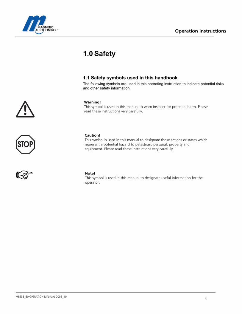
1.1 Safety symbols used in this handbook The following symbols are used in this operating instruction to indicate potential risks and other safety information.
Caution! This symbol is used in this manual to designate those actions or states which represent a potential hazard to petestrian, personal, property and equipment. Please read these instructions very carefully.
Note! This symbol is used in this manual to designate useful information for the operator.
Warning! This symbol is used in this manual to warn installer for potential harm. Please read these instructions very carefully.
Operation Instructions
MBE35_50 OPERATION MANUAL 2005_10 - 5 -
1.2 General safety information The MAGSTOP barrier system has been designed, built and tested using state-of-the-art technology and left our factory only after passing stringent safety and reliability criteria. Nevertheless, the barrier system can represent a risk to persons and property if it is not installed and operated correctly. These operating instructions must therefore be read in their entirety and all safety information contained therein must be complied with. The manufacturer shall refuse to accept liability and shall withdraw warranty if this barrier system is used incorrectly or is used for a purpose for which it was not intended.
1.3 Intended use The MAGSTOP MBE 35/50 barriers are designed to control vehicular (see pictogram below) access and exits to car parks, car parking garages, access control applications and highways. The MAGTRONIC control units have been specially designed for controlling Magnetic barriers. Any other use of these barrier systems is not permitted. Modifications or changes to the barrier or to the control modules are prohibited. Only original Magnetic spare parts and accessories shall be used.
1.4 Warning and safety signage The Magnetic Automation Corp. MIB barriers come with two (2) safety-warning labels (see Figure 1 above) that must be applied to the barrier housing so it can easily be seen when a pedestrian, bicycle users, or motorized vehicle uses the lane. Magnetic Automation Corp. requires that you use universally identifiable pictograms in all entrance/exit lanes, roadways, post, and walls. It is strongly recommended to paint a “NO PEDESTRIAN” pictogram on the roadway immediately adjacent to the parking barrier gate.
Figure 1
Operation Instructions
MBE35_50 OPERATION MANUAL 2005_10 6
1.5 Safety Requirements - Use vibrant colors on parking equipment - Always provide proper signage, both on the road way and on other equipment - Maintain manufacturers warning stickers on gate housing and gate arms. - Always require that sidewalks are parallel to entrance and exit lanes, or require having pedestrian entrances on opposite side of vehicle entrance and exit.
IMPORTANT: It is A MUST to have pedestrian sidewalks installed parallel to entrance and exit lanes or to have pedestrian walkways on the opposite sides of the facility away of vehicle traffic. It is also necessary to enforce that pedestrian are using those walkways and do not enter or leave the parking facility on vehicle traffic lanes. NOTE: NOT COMPLYANCE WITH THE ABOVE SAFETY REQUIREMENTS (Chapter 1.3 and 1.4) SHALL VOID ANY MANUFACTURERS LIABILITY!
Operation Instructions
MBE35_50 OPERATION MANUAL 2005_10 - 7 -
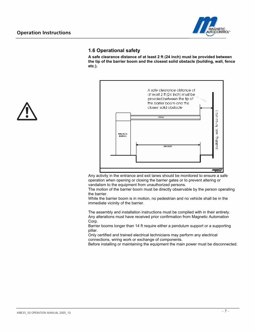
1.6 Operational safety A safe clearance distance of at least 2 ft (24 inch) must be provided between the tip of the barrier boom and the closest solid obstacle (building, wall, fence etc.).
Any activity in the entrance and exit lanes should be monitored to ensure a safe operation when opening or closing the barrier gates or to prevent altering or vandalism to the equipment from unauthorized persons. The motion of the barrier boom must be directly observable by the person operating the barrier. While the barrier boom is in motion, no pedestrian and no vehicle shall be in the immediate vicinity of the barrier.
The assembly and installation instructions must be complied with in their entirety. Any alterations must have received prior confirmation from Magnetic Automation Corp. Barrier booms longer than 14 ft require either a pendulum support or a supporting pillar. Only certified and trained electrical technicians may perform any electrical connections, wiring work or exchange of components. Before installing or maintaining the equipment the main power must be disconnected.
Operation Instructions
MBE35_50 OPERATION MANUAL 2005_10 8
1.7 Technical developments The manufacturer reserves the right to modify, without prior notice, the technical specifications in order to accommodate the latest technical developments. Magnetic Automation Corp. will provide information on the status of existing operating instructions and on any alterations and extensions that may be relevant.
1.8 Warranty Magnetic provides a limited warranty on its barriers that covers all mechanical and electrical components, but excludes parts subject to wear and tear, for a period of two years from the date of first use or for a maximum of three years from the date on which the system was delivered provided that the operating instructions have been complied with, no unauthorized servicing of machine components has taken place, and that no mechanical damage to the machines is evident. Please refer to our Warranty Statement.
COPYRIGHT 2002 Magnetic Automation Corp. All rights reserved. No part of this publication may be reproduced, transmitted, transcribed, stored in a retrieval system, or translated into any language in any form by any means without the written permission of Magnetic Automation Corp. First Printing: 2002
Operation Instructions
MBE35_50 OPERATION MANUAL 2005_10 - 9 -
2.0 Installation
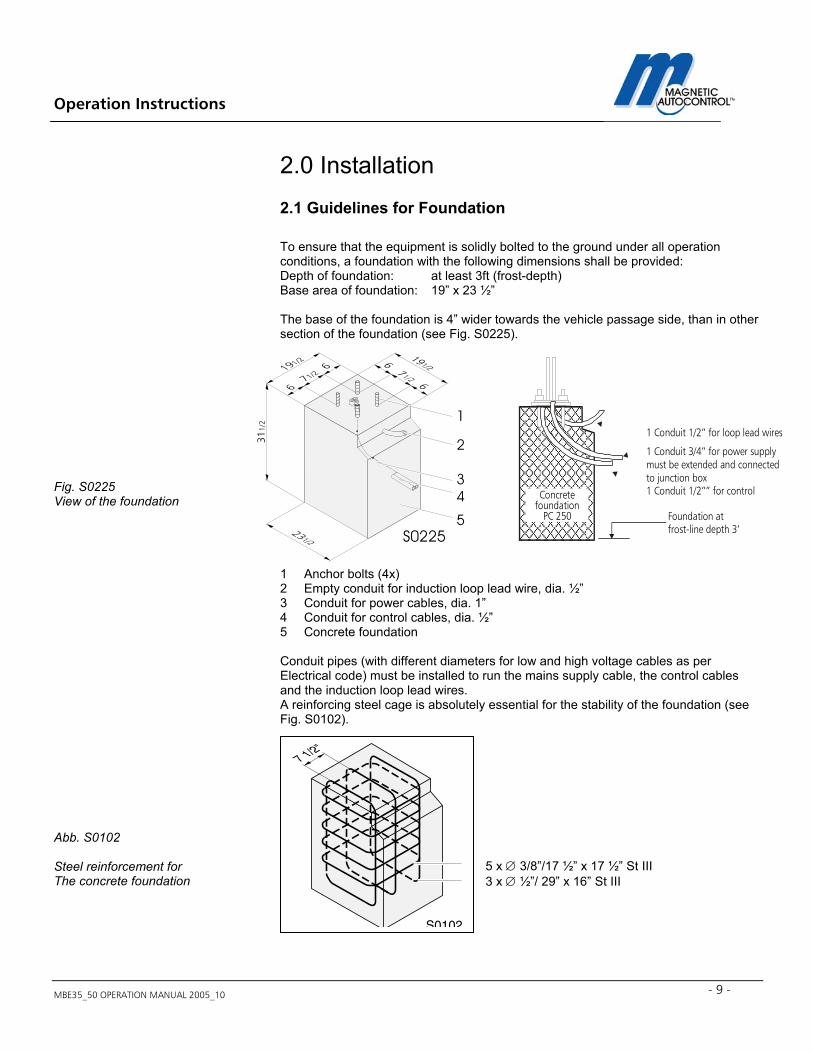
2.1 Guidelines for Foundation To ensure that the equipment is solidly bolted to the ground under all operation conditions, a foundation with the following dimensions shall be provided: Depth of foundation: at least 3ft (frost-depth) Base area of foundation: 19” x 23 ½” The base of the foundation is 4” wider towards the vehicle passage side, than in other section of the foundation (see Fig. S0225).
Fig. S0225 View of the foundation
1 Anchor bolts (4x) 2 Empty conduit for induction loop lead wire, dia. ½” 3 Conduit for power cables, dia. 1” 4 Conduit for control cables, dia. ½” 5 Concrete foundation Conduit pipes (with different diameters for low and high voltage cables as per Electrical code) must be installed to run the mains supply cable, the control cables and the induction loop lead wires. A reinforcing steel cage is absolutely essential for the stability of the foundation (see Fig. S0102).
Abb. S0102 Steel reinforcement for The concrete foundation
5 x ∅ 3/8”/17 ½” x 17 ½” St III 3 x ∅ ½”/ 29” x 16” St III
1 2 3 4
5
311/
2
S0225Foundation atfrost-line depth 3’
Concretefoundation
PC 250
1 Conduit 1/2” for loop lead wires
1 Conduit 3/4” for power supplymust be extended and connectedto junction box1 Conduit 1/2”” for control
Operation Instructions
MBE35_50 OPERATION MANUAL 2005_10 10
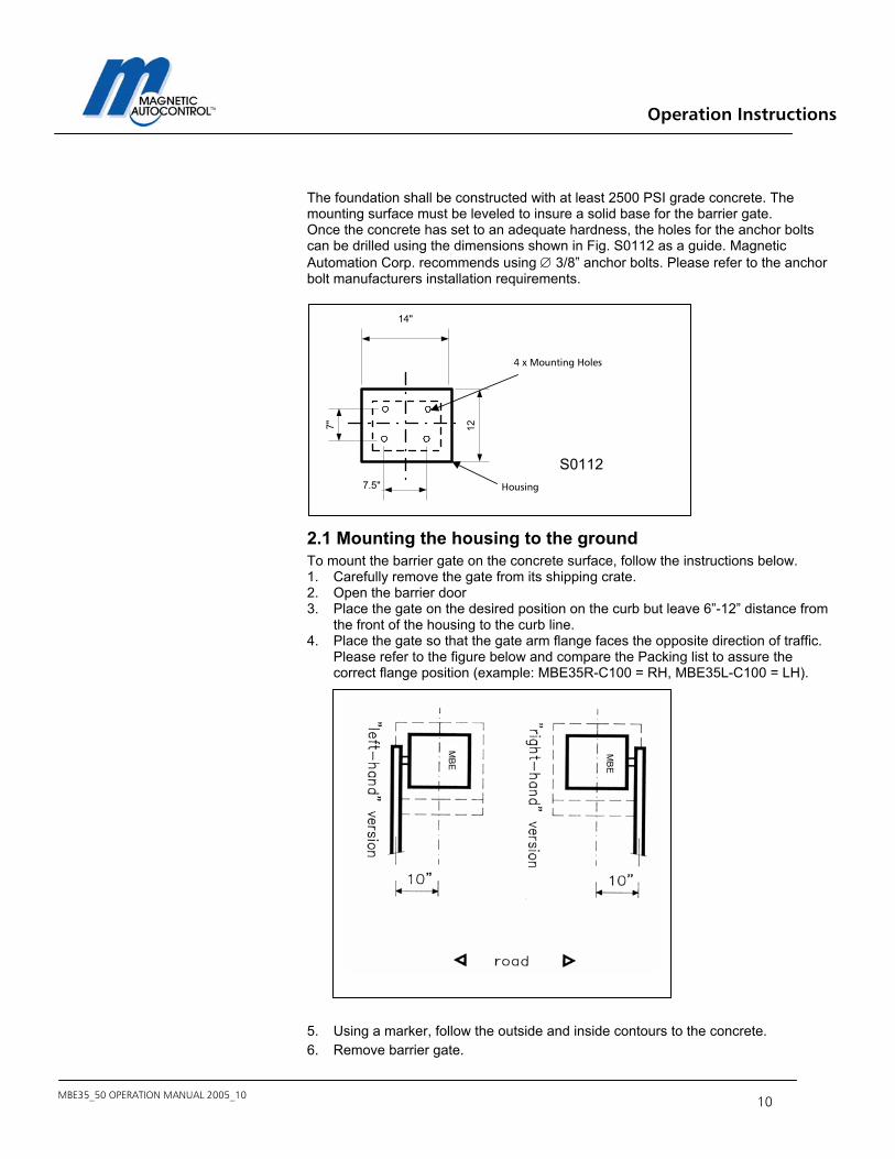
The foundation shall be constructed with at least 2500 PSI grade concrete. The mounting surface must be leveled to insure a solid base for the barrier gate. Once the concrete has set to an adequate hardness, the holes for the anchor bolts can be drilled using the dimensions shown in Fig. S0112 as a guide. Magnetic Automation Corp. recommends using ∅ 3/8” anchor bolts. Please refer to the anchor bolt manufacturers installation requirements.
2.1 Mounting the housing to the ground To mount the barrier gate on the concrete surface, follow the instructions below. 1. Carefully remove the gate from its shipping crate. 2. Open the barrier door 3. Place the gate on the desired position on the curb but leave 6”-12” distance from
the front of the housing to the curb line. 4. Place the gate so that the gate arm flange faces the opposite direction of traffic.
Please refer to the figure below and compare the Packing list to assure the correct flange position (example: MBE35R-C100 = RH, MBE35L-C100 = LH).
5. Using a marker, follow the outside and inside contours to the concrete. 6. Remove barrier gate.
7"
7.5"
14"
12
4 x Mounting Holes
Housing
S0112
MB
E
MB
E
Operation Instructions
MBE35_50 OPERATION MANUAL 2005_10 - 11 -
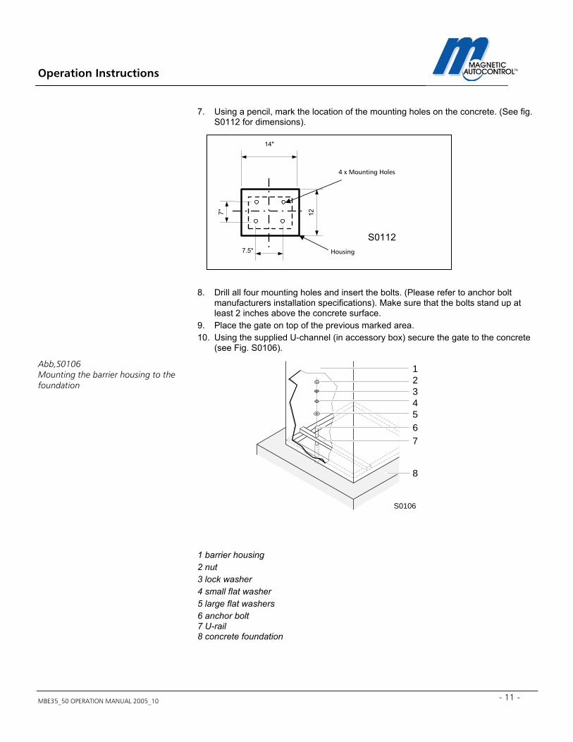
7. Using a pencil, mark the location of the mounting holes on the concrete. (See fig. S0112 for dimensions).
8. Drill all four mounting holes and insert the bolts. (Please refer to anchor bolt
manufacturers installation specifications). Make sure that the bolts stand up at least 2 inches above the concrete surface.
9. Place the gate on top of the previous marked area. 10. Using the supplied U-channel (in accessory box) secure the gate to the concrete
(see Fig. S0106). 1 barrier housing 2 nut 3 lock washer 4 small flat washer 5 large flat washers 6 anchor bolt 7 U-rail 8 concrete foundation
1234567
8
S0106
Abb,S0106 Mounting the barrier housing to the foundation
7"
7.5"
14"
12
4 x Mounting Holes
Housing
S0112
Operation Instructions
MBE35_50 OPERATION MANUAL 2005_10 12
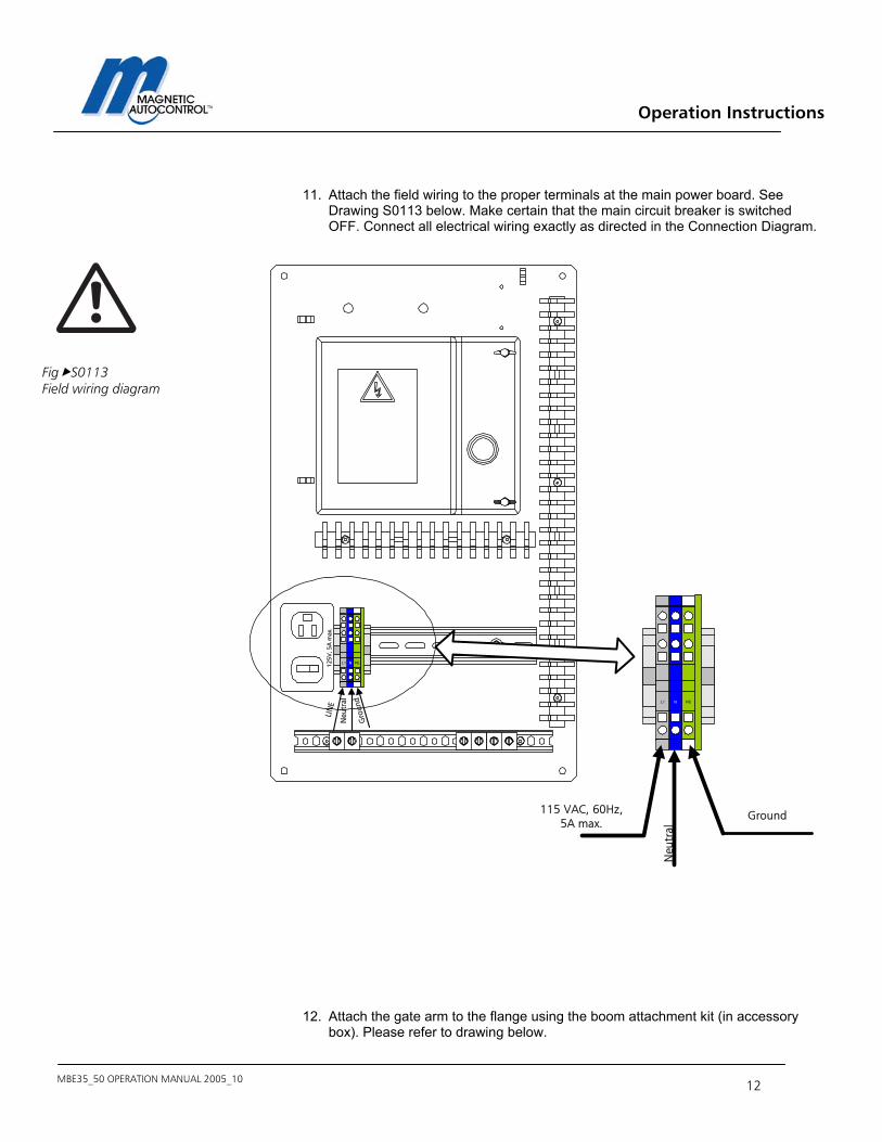
11. Attach the field wiring to the proper terminals at the main power board. See
Drawing S0113 below. Make certain that the main circuit breaker is switched OFF. Connect all electrical wiring exactly as directed in the Connection Diagram.
12. Attach the gate arm to the flange using the boom attachment kit (in accessory
box). Please refer to drawing below.
Fig S0113 Field wiring diagram
PENL1125V
, 5A
max
.LI
NE
Neu
tral
Gro
und PENL1
Neu
tral
115 VAC, 60Hz,5A max.
Ground
Operation Instructions
MBE35_50 OPERATION MANUAL 2005_10 - 13 -
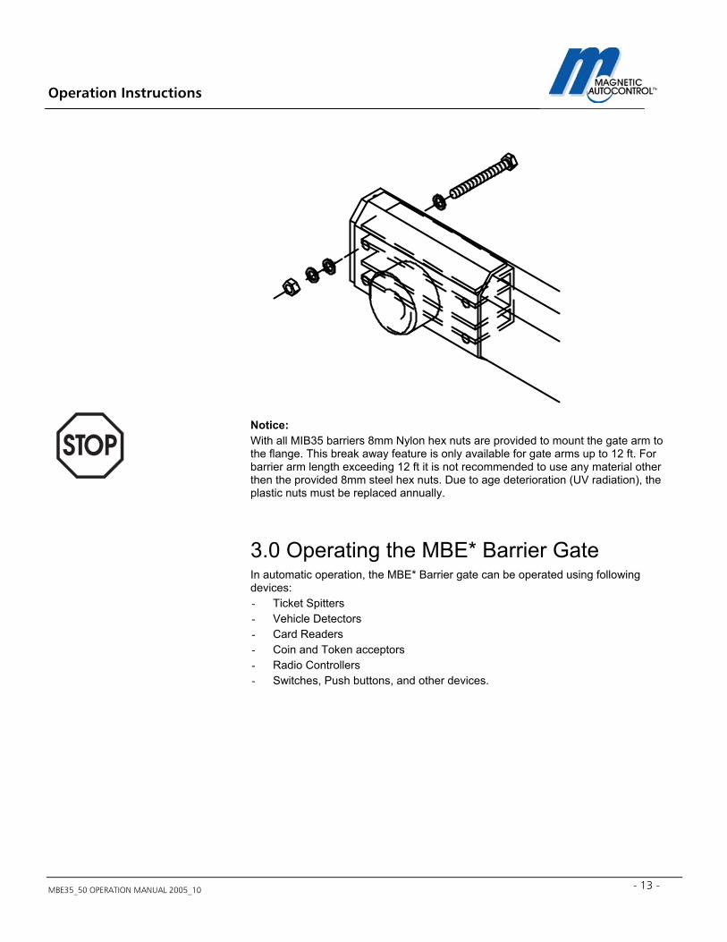
Notice: With all MIB35 barriers 8mm Nylon hex nuts are provided to mount the gate arm to the flange. This break away feature is only available for gate arms up to 12 ft. For barrier arm length exceeding 12 ft it is not recommended to use any material other then the provided 8mm steel hex nuts. Due to age deterioration (UV radiation), the plastic nuts must be replaced annually.
3.0 Operating the MBE* Barrier Gate In automatic operation, the MBE* Barrier gate can be operated using following devices: - Ticket Spitters - Vehicle Detectors - Card Readers - Coin and Token acceptors - Radio Controllers - Switches, Push buttons, and other devices.
Operation Instructions
MBE35_50 OPERATION MANUAL 2005_10 14
4.0 Controller
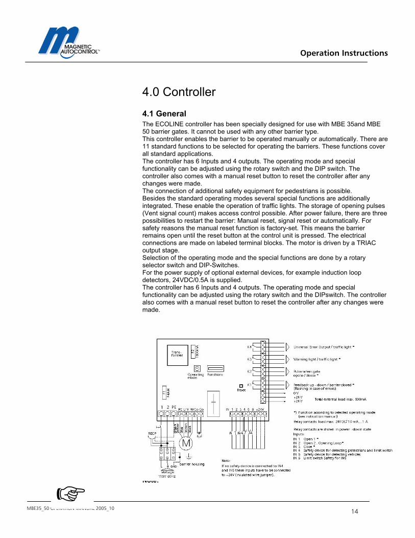
4.1 General The ECOLINE controller has been specially designed for use with MBE 35and MBE 50 barrier gates. It cannot be used with any other barrier type. This controller enables the barrier to be operated manually or automatically. There are 11 standard functions to be selected for operating the barriers. These functions cover all standard applications. The controller has 6 Inputs and 4 outputs. The operating mode and special functionality can be adjusted using the rotary switch and the DIP switch. The controller also comes with a manual reset button to reset the controller after any changes were made. The connection of additional safety equipment for pedestrians is possible. Besides the standard operating modes several special functions are additionally integrated. These enable the operation of traffic lights. The storage of opening pulses (Vent signal count) makes access control possible. After power failure, there are three possibilities to restart the barrier: Manual reset, signal reset or automatically. For safety reasons the manual reset function is factory-set. This means the barrier remains open until the reset button at the control unit is pressed. The electrical connections are made on labeled terminal blocks. The motor is driven by a TRIAC output stage. Selection of the operating mode and the special functions are done by a rotary selector switch and DIP-Switches. For the power supply of optional external devices, for example induction loop detectors, 24VDC/0.5A is supplied. The controller has 6 Inputs and 4 outputs. The operating mode and special functionality can be adjusted using the rotary switch and the DIPswitch. The controller also comes with a manual reset button to reset the controller after any changes were made. Note:

Operation Instructions
MBE35_50 OPERATION MANUAL 2005_10 - 15 -
Each in and output has a red LED- Indicator light to display which in- or output is currently activated. Light on = in- output active; Light off = in- output not active.
Operation Instructions
MBE35_50 OPERATION MANUAL 2005_10 16
Note: IN5 (external safety input) and IN4 (pedestrian safety input) must be made (activated) in order for the barrier gate to operate. Standard factory setup is a jumper wire to activate these inputs. When installing the safety devices a normally closed contact must be used for both inputs and the factory wired jumper must be removed. Attention: Remove the factory wired jumper only if you use the input!
4.2 Controller Inputs The MBE controller has 6 digital inputs (IN = Input). All inputs require a potential free contact. Following is a description of the individual inputs: IN 1: Gate open input for operating modes 2,4 - B. Requires a potential free
normally open contact from an access control device, push button etc. Higher priority than IN2 and IN3. As long as this input is made, the gate will not close. In the dynamic operating modes 5, 6, 9, and A this input starts the hold open time. In the operating modes 8, 9, A, and B this input increments the vent count.
IN 2: Opening loop input. Requires a potential free normally open contact from an
inductive opening loop. The open hold time will not be set in any of the modes.
IN 3: Gate close input. Requires a potential free a normally open contact. This
input will close the gate as long as none of the safety inputs IN4 and IN5 or IN1 is activated.
IN 4: Pedestrian safety input. Used for safety edges or photo beams.
Requires a potential free normally closed contact. If the safety device detects a pedestrian while closing it will reopen the barrier and stay up for 5sec. If the gate is up while a pedestrian or object is detected at IN4 it will not close until the safety zone is cleared. This input can be disabled with an optional limit switch.
IN 5: Vehicle safety/closing device input. Used for inductive loops and photo
beams. For example safety/closing inductive loop detector. Requires a potential free normally closed contact. If the safety device detects a vehicle while closing it will reopen the barrier and stay open until the vehicle leaves the detection zone. If the gate is up while a vehicle or object is detected at IN5, it will not close until the safety zone is cleared. This input is disabled when the gate arm is in the down position by the down limit switch on IN6.
IN 6: Limit switch input. This limit switch is installed EX factory in all MBE35 and
50 barriers. It has following functionality:
Operation Instructions
MBE35_50 OPERATION MANUAL 2005_10 - 17 -
1. Disabling of safety/closing devices connected to IN5 when the gate is in the down position. 2. The limit switch provides the controller logic with the information that the gate is in the down position. 3. If the controller is setup for signal reset (see chapter 4.5 DIP Switch 2) it uses the limit switch feedback to determine in what position the gate is when the main power returns after it was off. 4. If a warning signal is used on output relay K 3 (see chapter 4.3 and 4.5) the signal will stay on for 5sec. after the controller received the feedback from this limit switch that it is in the down position.
Operation Instructions
MBE35_50 OPERATION MANUAL 2005_10 18
4.3 Controller outputs The MBE controller has 4 relay outputs (K* = Output). The output relay contacts are rated for 24 VDC/ 1A. Following is a description of the individual outputs: K 1: Depending on DIP switch 5 settings:
DIP switch 5 in off position: Motor drive indication. Relay is active as soon as gate starts to come down. DIPswitch 5 in ON position: Gate closed indication. Relay is active as soon as the gate is in full closed position, depending on limit switch settings. This relay output, independent of the DIPswitch setting, will cycle between on and off when a gate failure occurred or right after the power is turned on. In this case pushing the RESET button will get the controller in the operating mode.
K2: Depending on DIP-switch 6 settings.
DIPswitch 6 in off position: 500ms pulse signal when barrier is open and a vehicle passed through the safety/closing device connected to IN5. DIPswitch 6 in on position: 500ms pulse signal when the controller received in input on IN1 gate open.
K3: Depending on DIP-switch 7 settings.
DIPswitch 7 in off position: This output is used to turn warning signals (lights or horns) on prior to closing the barrier. For example turning on a red light to alarm people that the gate will close soon. The light will turn off after 5 seconds after the gate closed. DIPswitch 7 in on position: This output is used to turn warning signals (lights or horns) on prior to closing the barrier. For example turning on a red light to alarm people that the gate will close soon. The light will remain on as long as the gate is in the down position.
K4: Depending on DIP-switch 8 settings. DIP switch 8 in off position: Universal error output. If red LED is on no error. Gate failures reported are: run time error in case the end limit switch is not activated when the gate is in the down position, controller is waiting for a manual or signal reset, safety inputs IN4 and IN5 are occupied longer than 3 minutes, in case of a power failure of the 24V or 5V supply. DIPswitch 8 in ON position: same functionality as K3 (DIP switch 7 on).
Operation Instructions
MBE35_50 OPERATION MANUAL 2005_10 - 19 -
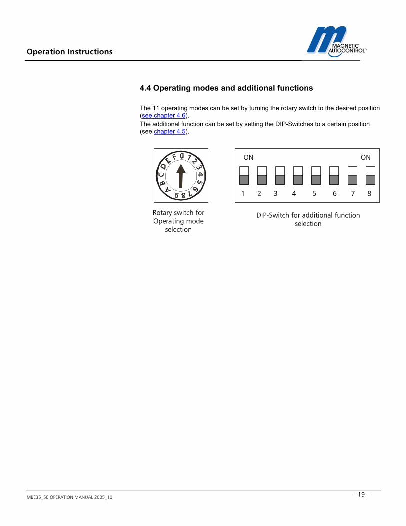
4.4 Operating modes and additional functions The 11 operating modes can be set by turning the rotary switch to the desired position (see chapter 4.6). The additional function can be set by setting the DIP-Switches to a certain position (see chapter 4.5).
Rotary switch forOperating mode
selection
1 2 3 4 5 6 7 8
ON ON
DIP-Switch for additional functionselection
Operation Instructions
MBE35_50 OPERATION MANUAL 2005_10 20
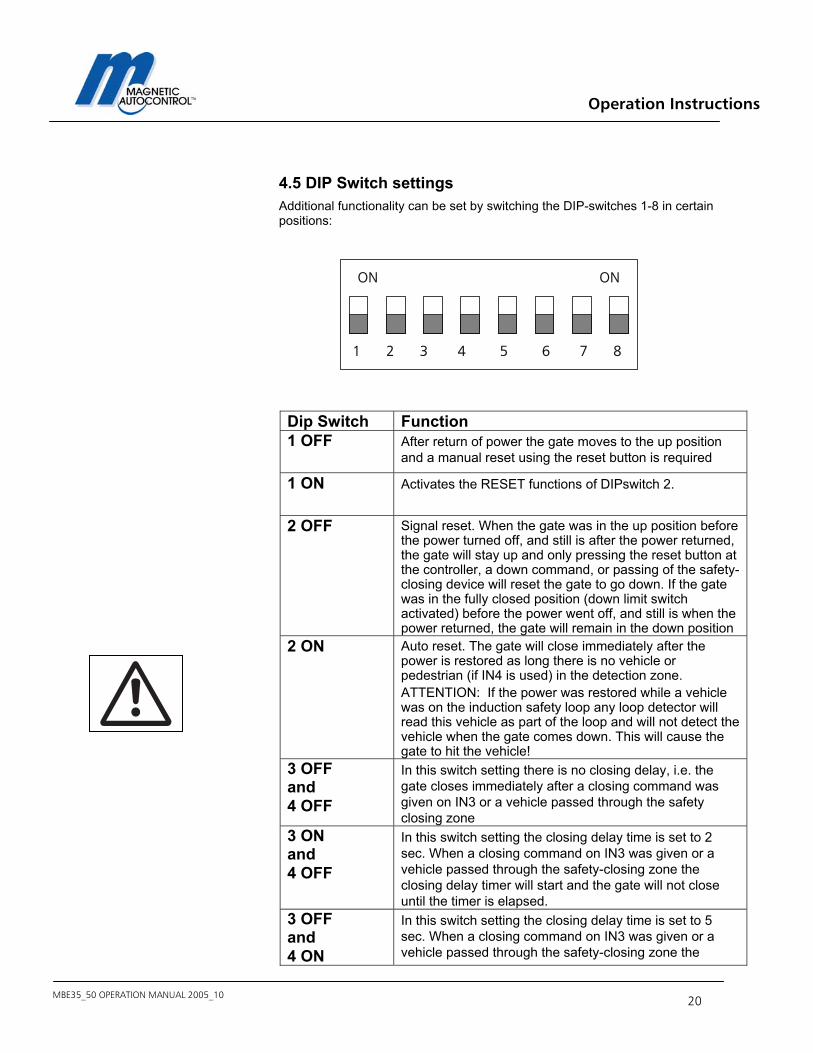
4.5 DIP Switch settings Additional functionality can be set by switching the DIP-switches 1-8 in certain positions:
Dip Switch Function 1 OFF After return of power the gate moves to the up position
and a manual reset using the reset button is required
1 ON Activates the RESET functions of DIPswitch 2.
2 OFF Signal reset. When the gate was in the up position before the power turned off, and still is after the power returned, the gate will stay up and only pressing the reset button at the controller, a down command, or passing of the safety-closing device will reset the gate to go down. If the gate was in the fully closed position (down limit switch activated) before the power went off, and still is when the power returned, the gate will remain in the down position
2 ON Auto reset. The gate will close immediately after the power is restored as long there is no vehicle or pedestrian (if IN4 is used) in the detection zone. ATTENTION: If the power was restored while a vehicle was on the induction safety loop any loop detector will read this vehicle as part of the loop and will not detect the vehicle when the gate comes down. This will cause the gate to hit the vehicle!
3 OFF and 4 OFF
In this switch setting there is no closing delay, i.e. the gate closes immediately after a closing command was given on IN3 or a vehicle passed through the safety closing zone
3 ON and 4 OFF
In this switch setting the closing delay time is set to 2 sec. When a closing command on IN3 was given or a vehicle passed through the safety-closing zone the closing delay timer will start and the gate will not close until the timer is elapsed.
3 OFF and 4 ON
In this switch setting the closing delay time is set to 5 sec. When a closing command on IN3 was given or a vehicle passed through the safety-closing zone the
1 2 3 4 5 6 7 8
ON ON

Operation Instructions
MBE35_50 OPERATION MANUAL 2005_10 - 21 -
closing delay timer will start and the gate will not close until the timer is elapsed.
3 ON and 4 ON
In this switch setting the closing delay time is set to 9 sec. When a closing command on IN3 was given or a vehicle passed through the safety-closing zone the closing delay timer will start and the gate will not close until the timer is elapsed.
4 OFF This switch sets the closing delay time to 2 sec. When a closing command on IN3 was given or a vehicle passed through the safety-closing zone the closing delay timer will start and the gate will not close until the timer is elapsed.
4 ON This switch sets the closing delay time to 5 sec. When a closing command on IN3 was given or a vehicle passed through the safety-closing zone the closing delay timer will start and the gate will not close until the timer is elapsed.
5 OFF Relay K1 active when gate starts to open. Indication of motor drive direction. Relay cycles on/off when a gate failure occurred.
5 ON Relay K1 active when gate is in fully closed position (depending on how the down limit switch is set). Relay cycles on/off when a gate failure occurred.
6 OFF Relay K2, 500ms pulse when passing the safety/closing device connected on IN5.
6 ON Relay K2, 500ms pulse when gate opens 7 OFF Relay K3; For warning signals (Lights and horns).
Depending on the DIP switch settings 3 and 4 this relay will turn on and off warning signals to alert patrons that the gate will soon close. The relay will stay active 5 sec. after the gate reached the down limit switch.
7 ON Relay K3; For red/green traffic lights. The relay is activated as soon as a closing command on IN3 is given or a vehicle passed through the safety-closing device. The gate will close after the closing delay timer (DIPswitch 3 and 4) is elapsed. The relay will stay active until an opening command to IN1 or 2 was provided.
Operation Instructions
MBE35_50 OPERATION MANUAL 2005_10 22
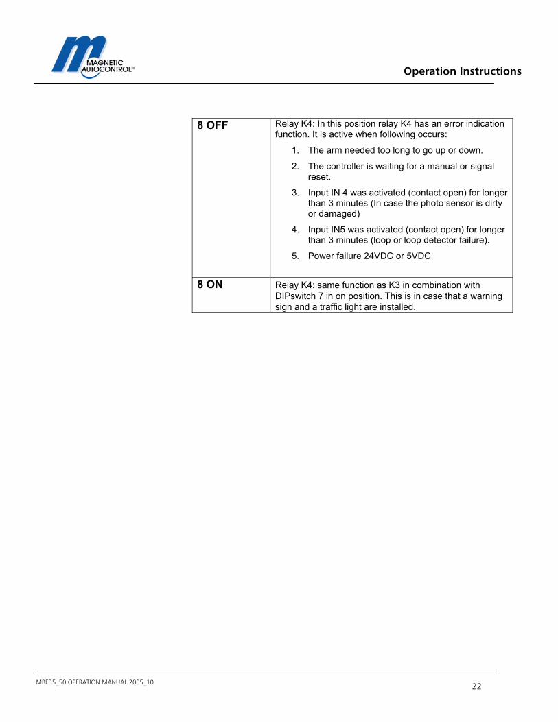
8 OFF Relay K4: In this position relay K4 has an error indication
function. It is active when following occurs:
1. The arm needed too long to go up or down.
2. The controller is waiting for a manual or signal reset.
3. Input IN 4 was activated (contact open) for longer than 3 minutes (In case the photo sensor is dirty or damaged)
4. Input IN5 was activated (contact open) for longer than 3 minutes (loop or loop detector failure).
5. Power failure 24VDC or 5VDC
8 ON Relay K4: same function as K3 in combination with
DIPswitch 7 in on position. This is in case that a warning sign and a traffic light are installed.
Operation Instructions
MBE35_50 OPERATION MANUAL 2005_10 - 23 -
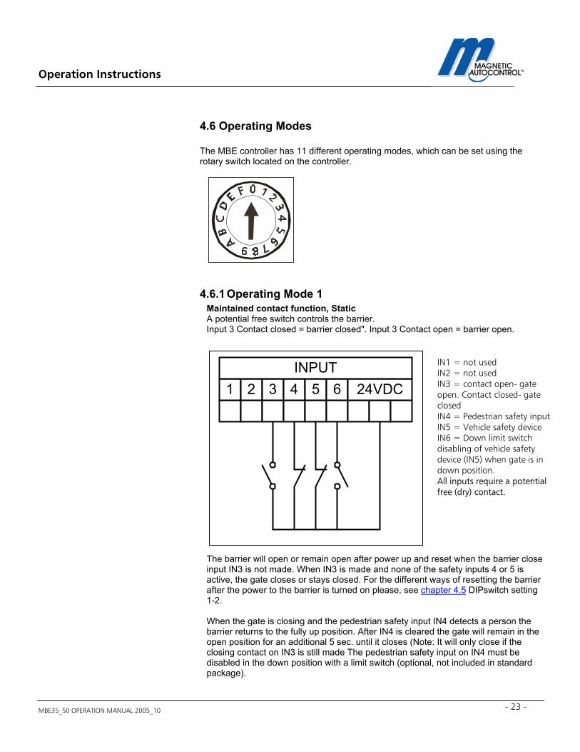
4.6 Operating Modes The MBE controller has 11 different operating modes, which can be set using the rotary switch located on the controller.
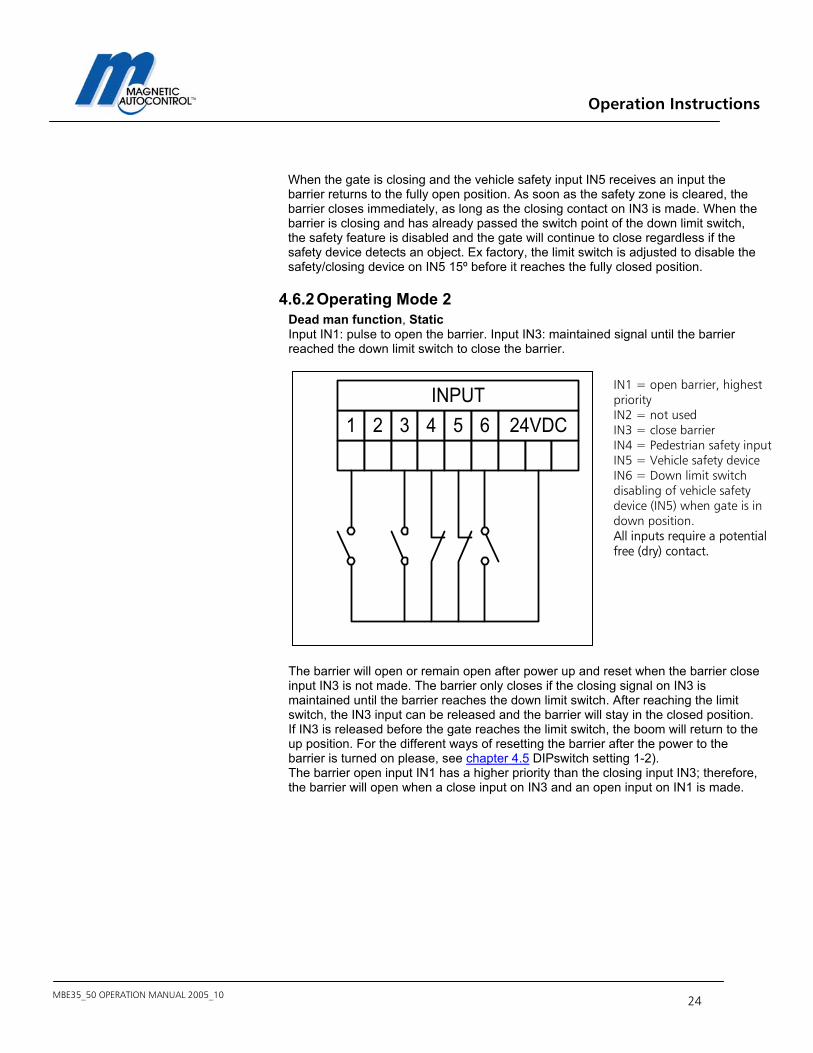
4.6.1 Operating Mode 1 Maintained contact function, Static A potential free switch controls the barrier. Input 3 Contact closed = barrier closed". Input 3 Contact open = barrier open.
The barrier will open or remain open after power up and reset when the barrier close input IN3 is not made. When IN3 is made and none of the safety inputs 4 or 5 is active, the gate closes or stays closed. For the different ways of resetting the barrier after the power to the barrier is turned on please, see chapter 4.5 DIPswitch setting 1-2.
When the gate is closing and the pedestrian safety input IN4 detects a person the barrier returns to the fully up position. After IN4 is cleared the gate will remain in the open position for an additional 5 sec. until it closes (Note: It will only close if the closing contact on IN3 is still made The pedestrian safety input on IN4 must be disabled in the down position with a limit switch (optional, not included in standard package).
1 2 3 4 5 6 24VDCINPUT
IN1 = not used IN2 = not used IN3 = contact open- gate open. Contact closed- gate closed IN4 = Pedestrian safety input IN5 = Vehicle safety device IN6 = Down limit switch disabling of vehicle safety device (IN5) when gate is in down position. All inputs require a potential free (dry) contact.
Operation Instructions
MBE35_50 OPERATION MANUAL 2005_10 24
When the gate is closing and the vehicle safety input IN5 receives an input the barrier returns to the fully open position. As soon as the safety zone is cleared, the barrier closes immediately, as long as the closing contact on IN3 is made. When the barrier is closing and has already passed the switch point of the down limit switch, the safety feature is disabled and the gate will continue to close regardless if the safety device detects an object. Ex factory, the limit switch is adjusted to disable the safety/closing device on IN5 15º before it reaches the fully closed position.
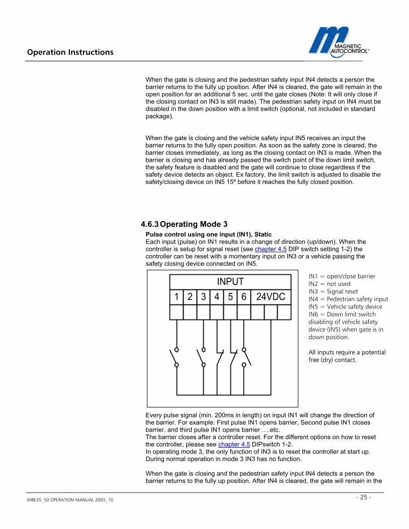
4.6.2 Operating Mode 2 Dead man function, Static Input IN1: pulse to open the barrier. Input IN3: maintained signal until the barrier reached the down limit switch to close the barrier.
The barrier will open or remain open after power up and reset when the barrier close input IN3 is not made. The barrier only closes if the closing signal on IN3 is maintained until the barrier reaches the down limit switch. After reaching the limit switch, the IN3 input can be released and the barrier will stay in the closed position. If IN3 is released before the gate reaches the limit switch, the boom will return to the up position. For the different ways of resetting the barrier after the power to the barrier is turned on please, see chapter 4.5 DIPswitch setting 1-2). The barrier open input IN1 has a higher priority than the closing input IN3; therefore, the barrier will open when a close input on IN3 and an open input on IN1 is made.
1 2 3 4 5 6 24VDCINPUT
IN1 = open barrier, highest priority IN2 = not used IN3 = close barrier IN4 = Pedestrian safety input IN5 = Vehicle safety device IN6 = Down limit switch disabling of vehicle safety device (IN5) when gate is in down position. All inputs require a potential free (dry) contact.
Operation Instructions
MBE35_50 OPERATION MANUAL 2005_10 - 25 -
When the gate is closing and the pedestrian safety input IN4 detects a person the barrier returns to the fully up position. After IN4 is cleared, the gate will remain in the open position for an additional 5 sec. until the gate closes (Note: It will only close if the closing contact on IN3 is still made). The pedestrian safety input on IN4 must be disabled in the down position with a limit switch (optional, not included in standard package). When the gate is closing and the vehicle safety input IN5 receives an input the barrier returns to the fully open position. As soon as the safety zone is cleared, the barrier closes immediately, as long as the closing contact on IN3 is made. When the barrier is closing and has already passed the switch point of the down limit switch, the safety feature is disabled and the gate will continue to close regardless if the safety device detects an object. Ex factory, the limit switch is adjusted to disable the safety/closing device on IN5 15º before it reaches the fully closed position.
4.6.3 Operating Mode 3 Pulse control using one input (IN1), Static Each input (pulse) on IN1 results in a change of direction (up/down). When the controller is setup for signal reset (see chapter 4.5 DIP switch setting 1-2) the controller can be reset with a momentary input on IN3 or a vehicle passing the safety closing device connected on IN5.
Every pulse signal (min. 200ms in length) on input IN1 will change the direction of the barrier. For example: First pulse IN1 opens barrier, Second pulse IN1 closes barrier, and third pulse IN1 opens barrier ….etc. The barrier closes after a controller reset. For the different options on how to reset the controller, please see chapter 4.5 DIPswitch 1-2. In operating mode 3, the only function of IN3 is to reset the controller at start up. During normal operation in mode 3 IN3 has no function.
When the gate is closing and the pedestrian safety input IN4 detects a person the barrier returns to the fully up position. After IN4 is cleared, the gate will remain in the
1 2 3 4 5 6 24VDCINPUT
IN1 = open/close barrier IN2 = not used IN3 = Signal reset IN4 = Pedestrian safety input IN5 = Vehicle safety device IN6 = Down limit switch disabling of vehicle safety device (IN5) when gate is in down position. All inputs require a potential free (dry) contact.
Operation Instructions
MBE35_50 OPERATION MANUAL 2005_10 26
open position for an additional 5 sec. until it closes. The pedestrian safety input on IN4 must be disabled in the down position with a limit switch (optional, not included in standard package).
When the gate is closing and the vehicle safety input IN5 receives an input the barrier returns to the fully open position. As soon as the safety zone is cleared, the barrier closes immediately. When the barrier is closing and has already passed the switch point of the down limit switch, the safety feature is disabled and the gate will continue to close regardless if the safety device detects an object. Ex factory, the limit switch is adjusted to disable the safety/closing device on IN5 15º before it reaches the fully closed position.
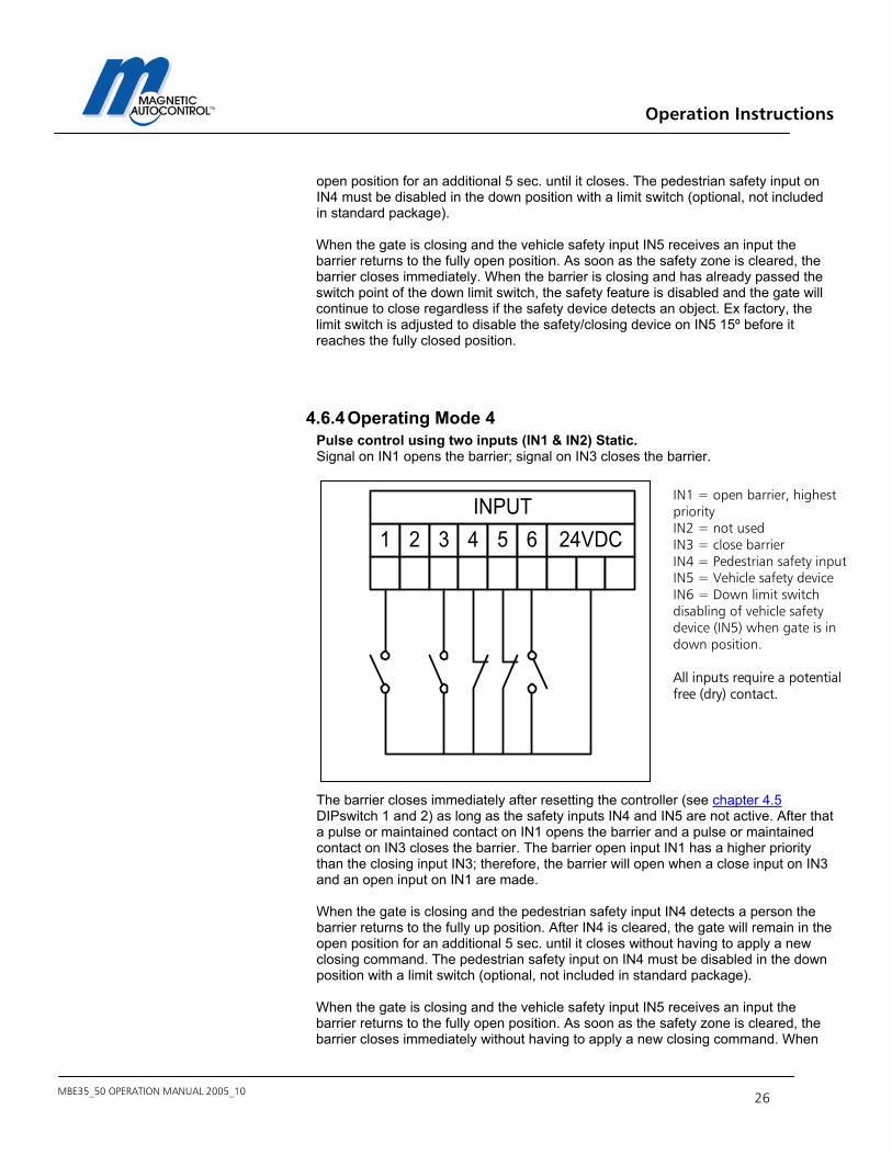
4.6.4 Operating Mode 4 Pulse control using two inputs (IN1 & IN2) Static. Signal on IN1 opens the barrier; signal on IN3 closes the barrier.
The barrier closes immediately after resetting the controller (see chapter 4.5 DIPswitch 1 and 2) as long as the safety inputs IN4 and IN5 are not active. After that a pulse or maintained contact on IN1 opens the barrier and a pulse or maintained contact on IN3 closes the barrier. The barrier open input IN1 has a higher priority than the closing input IN3; therefore, the barrier will open when a close input on IN3 and an open input on IN1 are made. When the gate is closing and the pedestrian safety input IN4 detects a person the barrier returns to the fully up position. After IN4 is cleared, the gate will remain in the open position for an additional 5 sec. until it closes without having to apply a new closing command. The pedestrian safety input on IN4 must be disabled in the down position with a limit switch (optional, not included in standard package).
When the gate is closing and the vehicle safety input IN5 receives an input the barrier returns to the fully open position. As soon as the safety zone is cleared, the barrier closes immediately without having to apply a new closing command. When
1 2 3 4 5 6 24VDCINPUT
IN1 = open barrier, highest priority IN2 = not used IN3 = close barrier IN4 = Pedestrian safety input IN5 = Vehicle safety device IN6 = Down limit switch disabling of vehicle safety device (IN5) when gate is in down position. All inputs require a potential free (dry) contact.
Operation Instructions
MBE35_50 OPERATION MANUAL 2005_10 - 27 -
the barrier is closing and has already passed the switch point of the down limit switch, the safety feature is disabled and the gate will continue to close regardless if the safety device detects an object. Ex factory, the limit switch is adjusted to disable the safety/closing device on IN5 15º before it reaches the fully closed position.
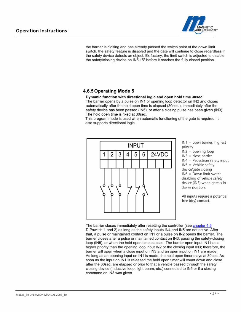
4.6.5 Operating Mode 5 Dynamic function with directional logic and open hold time 30sec. The barrier opens by a pulse on IN1 or opening loop detector on IN2 and closes automatically after the hold open time is elapsed (30sec.), immediately after the safety device has been passed (IN5), or after a closing pulse has been given (IN3). The hold open time is fixed at 30sec. This program mode is used when automatic functioning of the gate is required. It also supports directional logic.
The barrier closes immediately after resetting the controller (see chapter 4.5 DIPswitch 1 and 2) as long as the safety inputs IN4 and IN5 are not active. After that, a pulse or maintained contact on IN1 or a pulse on IN2 opens the barrier. The barrier closes after a pulse or maintained contact on IN3, passing the safety-closing loop (IN5), or when the hold open time elapses. The barrier open input IN1 has a higher priority than the opening loop input IN2 or the closing input IN3; therefore, the barrier will open when a close input on IN3 and an open input on IN1 are made. As long as an opening input on IN1 is made, the hold open timer stays at 30sec. As soon as the input on IN1 is released the hold open timer will count down and close after the 30sec. are elapsed or prior to that a vehicle passed through the safety closing device (inductive loop, light beam, etc.) connected to IN5 or if a closing command on IN3 was given.
1 2 3 4 5 6 24VDCINPUT
IN1 = open barrier, highest priority IN2 = opening loop IN3 = close barrier IN4 = Pedestrian safety input IN5 = Vehicle safety device/gate closing IN6 = Down limit switch disabling of vehicle safety device (IN5) when gate is in down position. All inputs require a potential free (dry) contact.
Operation Instructions
MBE35_50 OPERATION MANUAL 2005_10 28
When the gate is closing and the pedestrian safety input IN4 detects a person the barrier returns to the fully up position. After IN4 is cleared, the gate will remain in the open position for an additional 5 sec. until it closes without having to apply a new closing command. The pedestrian safety input on IN4 must be disabled in the down position with a limit switch (optional, not included in standard package).
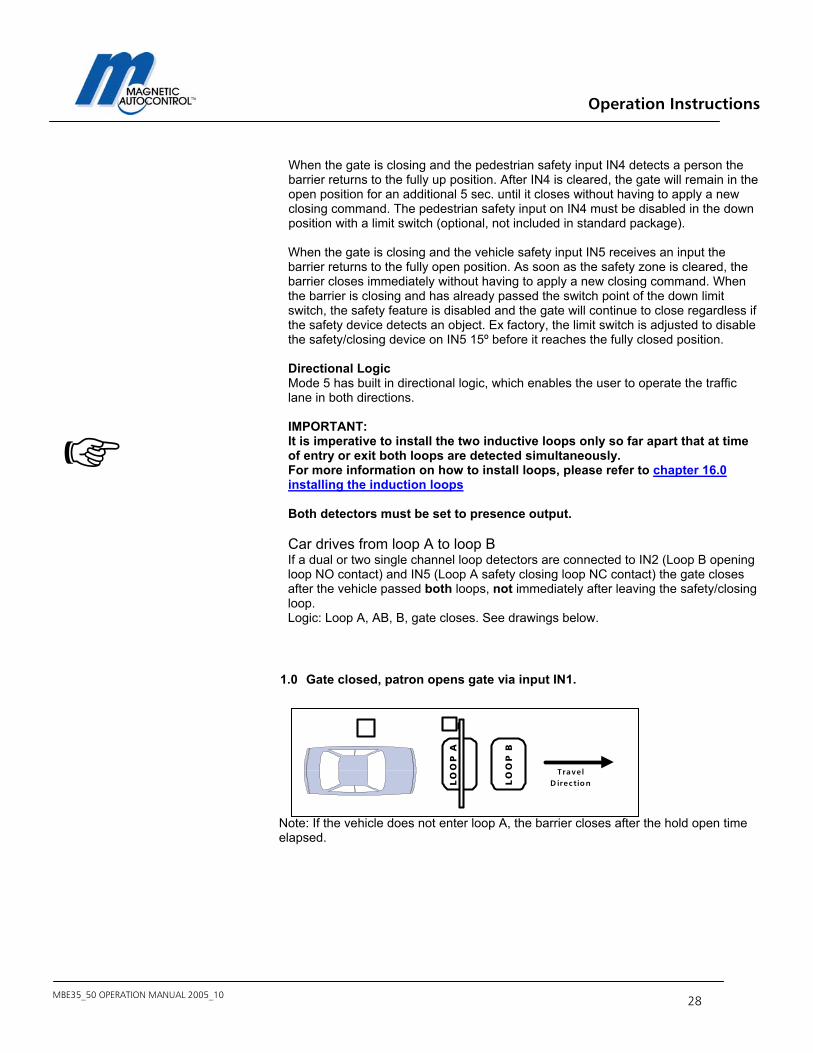
When the gate is closing and the vehicle safety input IN5 receives an input the barrier returns to the fully open position. As soon as the safety zone is cleared, the barrier closes immediately without having to apply a new closing command. When the barrier is closing and has already passed the switch point of the down limit switch, the safety feature is disabled and the gate will continue to close regardless if the safety device detects an object. Ex factory, the limit switch is adjusted to disable the safety/closing device on IN5 15º before it reaches the fully closed position. Directional Logic Mode 5 has built in directional logic, which enables the user to operate the traffic lane in both directions. IMPORTANT: It is imperative to install the two inductive loops only so far apart that at time of entry or exit both loops are detected simultaneously. For more information on how to install loops, please refer to chapter 16.0 installing the induction loops Both detectors must be set to presence output. Car drives from loop A to loop B If a dual or two single channel loop detectors are connected to IN2 (Loop B opening loop NO contact) and IN5 (Loop A safety closing loop NC contact) the gate closes after the vehicle passed both loops, not immediately after leaving the safety/closing loop. Logic: Loop A, AB, B, gate closes. See drawings below.
1.0 Gate closed, patron opens gate via input IN1.
Note: If the vehicle does not enter loop A, the barrier closes after the hold open time elapsed.
LO
OP
B
LO
OP
A
TravelD irection
Operation Instructions
MBE35_50 OPERATION MANUAL 2005_10 - 29 -
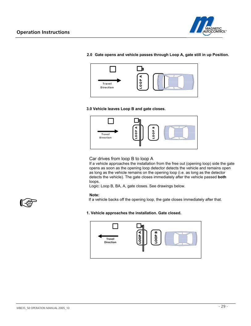
2.0 Gate opens and vehicle passes through Loop A, gate still in up Position. 3.0 Vehicle leaves Loop B and gate closes.
Car drives from loop B to loop A If a vehicle approaches the installation from the free out (opening loop) side the gate opens as soon as the opening loop detector detects the vehicle and remains open as long as the vehicle remains on the opening loop (i.e. as long as the detector detects the vehicle). The gate closes immediately after the vehicle passed both loops. Logic: Loop B, BA, A, gate closes. See drawings below.
Note: If a vehicle backs off the opening loop, the gate closes immediately after that. 1. Vehicle approaches the installation. Gate closed.
LO
OP
B
LO
OP
A
TravelD irection
LO
OP
B
LO
OP
ATrave l
D irection
LOO
P B
LOO
P A
TravelDirection
Operation Instructions
MBE35_50 OPERATION MANUAL 2005_10 30
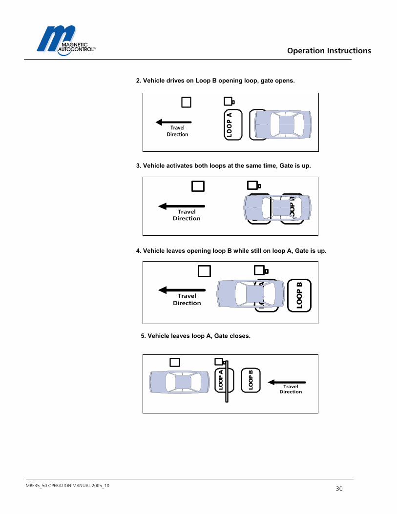
2. Vehicle drives on Loop B opening loop, gate opens.
3. Vehicle activates both loops at the same time, Gate is up.
4. Vehicle leaves opening loop B while still on loop A, Gate is up.
5. Vehicle leaves loop A, Gate closes.
LOO
P B
LOO
P A
TravelDirection
LOO
P B
LOO
P A
TravelDirection
LOO
P B
LOO
P A
TravelDirection
LOO
P B
LOO
P A
TravelDirection
Operation Instructions
MBE35_50 OPERATION MANUAL 2005_10 - 31 -
4.6.6 Operating Mode 6 Dynamic function with directional logic and open hold time 60sec.
Same as operating mode 5 but hold open time is fixed at 60 seconds.
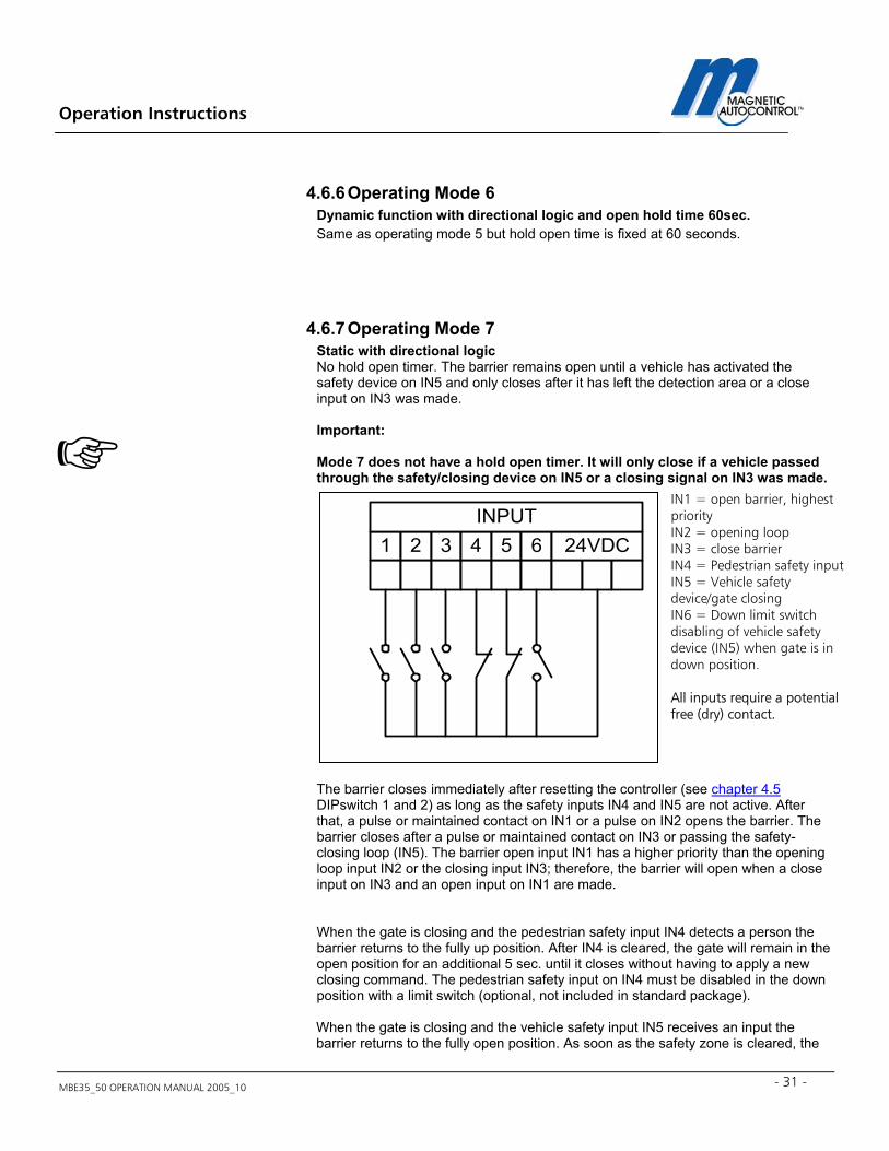
4.6.7 Operating Mode 7 Static with directional logic No hold open timer. The barrier remains open until a vehicle has activated the safety device on IN5 and only closes after it has left the detection area or a close input on IN3 was made. Important: Mode 7 does not have a hold open timer. It will only close if a vehicle passed through the safety/closing device on IN5 or a closing signal on IN3 was made.
The barrier closes immediately after resetting the controller (see chapter 4.5 DIPswitch 1 and 2) as long as the safety inputs IN4 and IN5 are not active. After that, a pulse or maintained contact on IN1 or a pulse on IN2 opens the barrier. The barrier closes after a pulse or maintained contact on IN3 or passing the safety-closing loop (IN5). The barrier open input IN1 has a higher priority than the opening loop input IN2 or the closing input IN3; therefore, the barrier will open when a close input on IN3 and an open input on IN1 are made.
When the gate is closing and the pedestrian safety input IN4 detects a person the barrier returns to the fully up position. After IN4 is cleared, the gate will remain in the open position for an additional 5 sec. until it closes without having to apply a new closing command. The pedestrian safety input on IN4 must be disabled in the down position with a limit switch (optional, not included in standard package).
When the gate is closing and the vehicle safety input IN5 receives an input the barrier returns to the fully open position. As soon as the safety zone is cleared, the
1 2 3 4 5 6 24VDCINPUT
IN1 = open barrier, highest priority IN2 = opening loop IN3 = close barrier IN4 = Pedestrian safety input IN5 = Vehicle safety device/gate closing IN6 = Down limit switch disabling of vehicle safety device (IN5) when gate is in down position. All inputs require a potential free (dry) contact.
Operation Instructions
MBE35_50 OPERATION MANUAL 2005_10 32
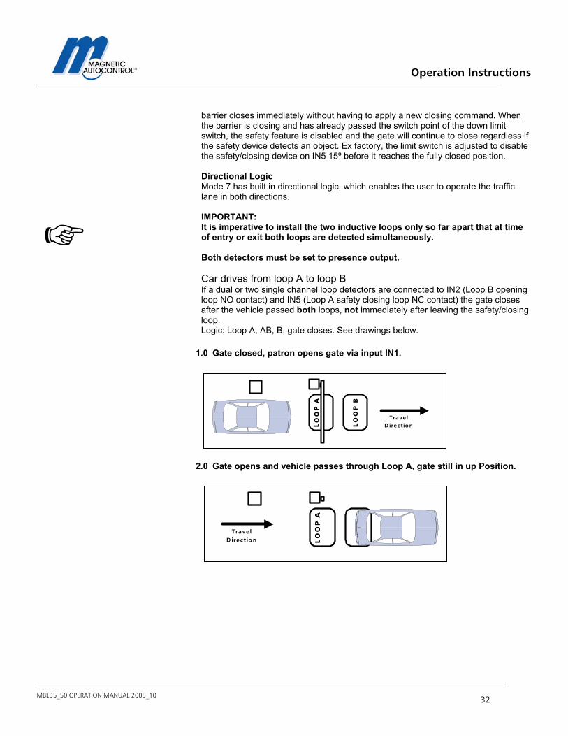
barrier closes immediately without having to apply a new closing command. When the barrier is closing and has already passed the switch point of the down limit switch, the safety feature is disabled and the gate will continue to close regardless if the safety device detects an object. Ex factory, the limit switch is adjusted to disable the safety/closing device on IN5 15º before it reaches the fully closed position. Directional Logic Mode 7 has built in directional logic, which enables the user to operate the traffic lane in both directions. IMPORTANT: It is imperative to install the two inductive loops only so far apart that at time of entry or exit both loops are detected simultaneously. Both detectors must be set to presence output. Car drives from loop A to loop B If a dual or two single channel loop detectors are connected to IN2 (Loop B opening loop NO contact) and IN5 (Loop A safety closing loop NC contact) the gate closes after the vehicle passed both loops, not immediately after leaving the safety/closing loop. Logic: Loop A, AB, B, gate closes. See drawings below.
1.0 Gate closed, patron opens gate via input IN1.
2.0 Gate opens and vehicle passes through Loop A, gate still in up Position.
LO
OP
B
LO
OP
A
TravelD irection
LO
OP
B
LO
OP
A
TravelD irection
Operation Instructions
MBE35_50 OPERATION MANUAL 2005_10 - 33 -
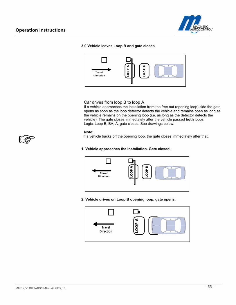
3.0 Vehicle leaves Loop B and gate closes.
Car drives from loop B to loop A If a vehicle approaches the installation from the free out (opening loop) side the gate opens as soon as the loop detector detects the vehicle and remains open as long as the vehicle remains on the opening loop (i.e. as long as the detector detects the vehicle). The gate closes immediately after the vehicle passed both loops. Logic: Loop B, BA, A, gate closes. See drawings below.
Note: If a vehicle backs off the opening loop, the gate closes immediately after that. 1. Vehicle approaches the installation. Gate closed.
2. Vehicle drives on Loop B opening loop, gate opens.
LO
OP
B
LO
OP
A
Trave lD irection
LOO
P B
LOO
P A
TravelDirection
LOO
P B
LOO
P A
TravelDirection
Operation Instructions
MBE35_50 OPERATION MANUAL 2005_10 34
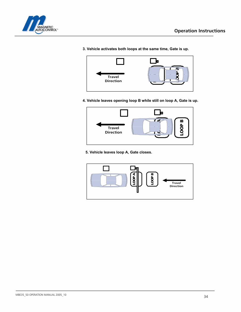
3. Vehicle activates both loops at the same time, Gate is up.
4. Vehicle leaves opening loop B while still on loop A, Gate is up.
5. Vehicle leaves loop A, Gate closes.
LOO
P B
LOO
P A
TravelDirection
LOO
P B
LOO
P A
TravelDirection
LOO
P B
LOO
P A
TravelDirection
Operation Instructions
MBE35_50 OPERATION MANUAL 2005_10 - 35 -
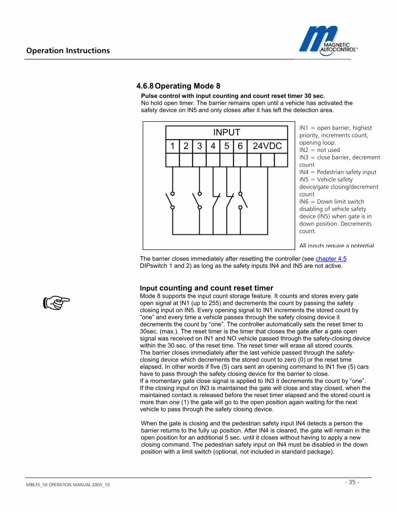
4.6.8 Operating Mode 8 Pulse control with input counting and count reset timer 30 sec. No hold open timer. The barrier remains open until a vehicle has activated the safety device on IN5 and only closes after it has left the detection area. The barrier closes immediately after resetting the controller (see chapter 4.5 DIPswitch 1 and 2) as long as the safety inputs IN4 and IN5 are not active. Input counting and count reset timer Mode 8 supports the input count storage feature. It counts and stores every gate open signal at IN1 (up to 255) and decrements the count by passing the safety closing input on IN5. Every opening signal to IN1 increments the stored count by “one” and every time a vehicle passes through the safety closing device it decrements the count by “one”. The controller automatically sets the reset timer to 30sec. (max.). The reset timer is the timer that closes the gate after a gate open signal was received on IN1 and NO vehicle passed through the safety-closing device within the 30 sec. of the reset time. The reset timer will erase all stored counts. The barrier closes immediately after the last vehicle passed through the safety-closing device which decrements the stored count to zero (0) or the reset time elapsed. In other words if five (5) cars sent an opening command to IN1 five (5) cars have to pass through the safety closing device for the barrier to close. If a momentary gate close signal is applied to IN3 it decrements the count by “one”. If the closing input on IN3 is maintained the gate will close and stay closed, when the maintained contact is released before the reset timer elapsed and the stored count is more than one (1) the gate will go to the open position again waiting for the next vehicle to pass through the safety closing device. When the gate is closing and the pedestrian safety input IN4 detects a person the barrier returns to the fully up position. After IN4 is cleared, the gate will remain in the open position for an additional 5 sec. until it closes without having to apply a new closing command. The pedestrian safety input on IN4 must be disabled in the down position with a limit switch (optional, not included in standard package).
IN1 = open barrier, highest priority, increments count, opening loop. IN2 = not used IN3 = close barrier, decrement count IN4 = Pedestrian safety input IN5 = Vehicle safety device/gate closing/decrement count IN6 = Down limit switch disabling of vehicle safety device (IN5) when gate is in down position. Decrements count. All inputs require a potential
1 2 3 4 5 6 24VDCINPUT
Operation Instructions
MBE35_50 OPERATION MANUAL 2005_10 36
When the gate is closing and the vehicle safety input IN5 receives an input the barrier returns to the fully open position. As soon as the safety zone is cleared, the barrier closes immediately without having to apply a new closing command. When the barrier is closing and has already passed the switch point of the down limit switch, the safety feature is disabled and the gate will continue to close regardless if the safety device detects an object. Ex factory, the limit switch is adjusted to disable the safety/closing device on IN5 15º before it reaches the fully closed position.
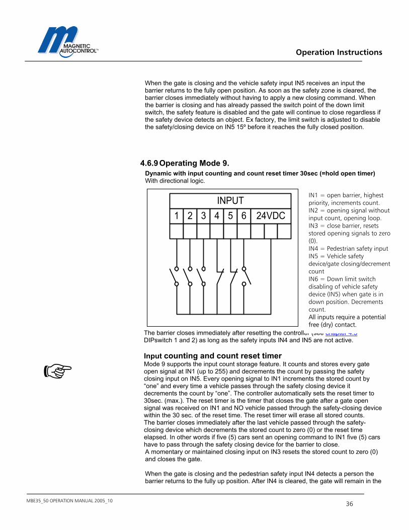
4.6.9 Operating Mode 9. Dynamic with input counting and count reset timer 30sec (=hold open timer) With directional logic.
The barrier closes immediately after resetting the controller (see chapter 4.5 DIPswitch 1 and 2) as long as the safety inputs IN4 and IN5 are not active. Input counting and count reset timer Mode 9 supports the input count storage feature. It counts and stores every gate open signal at IN1 (up to 255) and decrements the count by passing the safety closing input on IN5. Every opening signal to IN1 increments the stored count by “one” and every time a vehicle passes through the safety closing device it decrements the count by “one”. The controller automatically sets the reset timer to 30sec. (max.). The reset timer is the timer that closes the gate after a gate open signal was received on IN1 and NO vehicle passed through the safety-closing device within the 30 sec. of the reset time. The reset timer will erase all stored counts. The barrier closes immediately after the last vehicle passed through the safety-closing device which decrements the stored count to zero (0) or the reset time elapsed. In other words if five (5) cars sent an opening command to IN1 five (5) cars have to pass through the safety closing device for the barrier to close. A momentary or maintained closing input on IN3 resets the stored count to zero (0) and closes the gate. When the gate is closing and the pedestrian safety input IN4 detects a person the barrier returns to the fully up position. After IN4 is cleared, the gate will remain in the
1 2 3 4 5 6 24VDCINPUT
IN1 = open barrier, highest priority, increments count. IN2 = opening signal without input count, opening loop. IN3 = close barrier, resets stored opening signals to zero (0). IN4 = Pedestrian safety input IN5 = Vehicle safety device/gate closing/decrement count IN6 = Down limit switch disabling of vehicle safety device (IN5) when gate is in down position. Decrements count. All inputs require a potential free (dry) contact.
Operation Instructions
MBE35_50 OPERATION MANUAL 2005_10 - 37 -
open position for an additional 5 sec. until it closes without having to apply a new closing command. The pedestrian safety input on IN4 must be disabled in the down position with a limit switch (optional, not included in standard package).
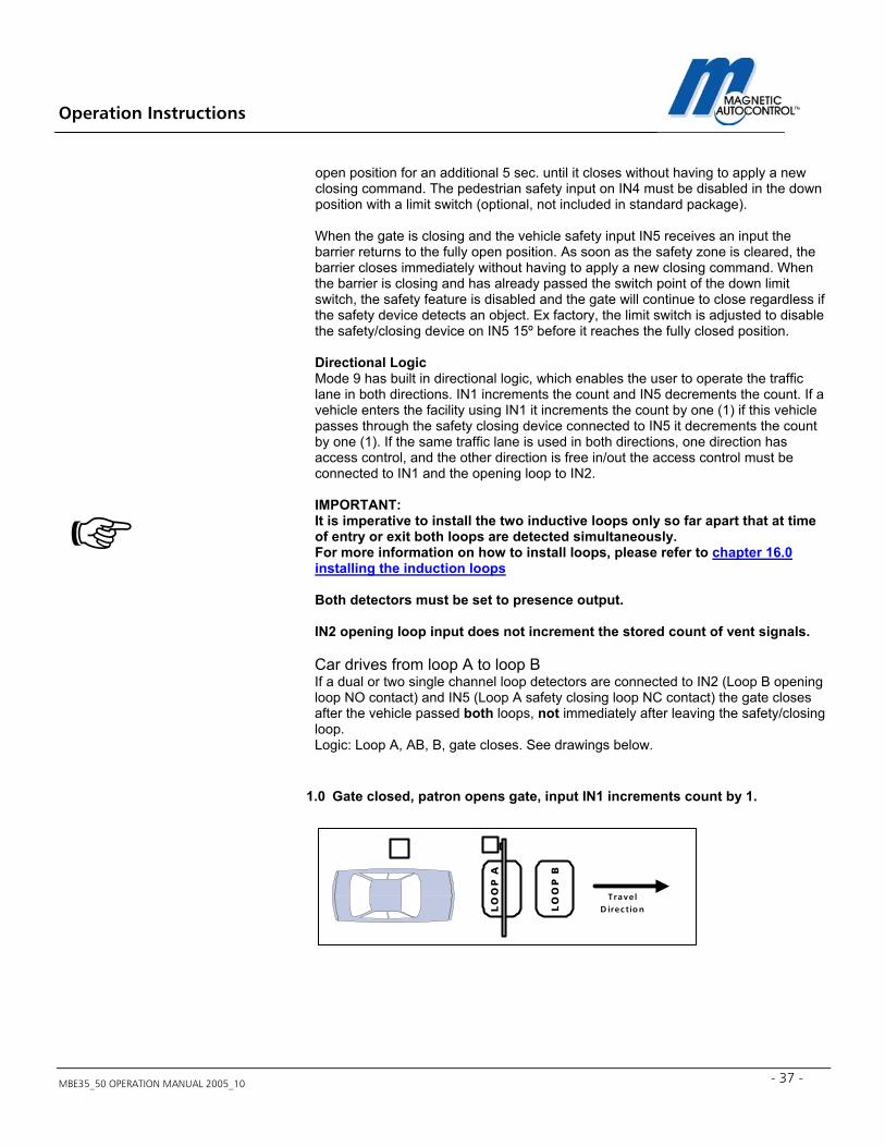
When the gate is closing and the vehicle safety input IN5 receives an input the barrier returns to the fully open position. As soon as the safety zone is cleared, the barrier closes immediately without having to apply a new closing command. When the barrier is closing and has already passed the switch point of the down limit switch, the safety feature is disabled and the gate will continue to close regardless if the safety device detects an object. Ex factory, the limit switch is adjusted to disable the safety/closing device on IN5 15º before it reaches the fully closed position. Directional Logic Mode 9 has built in directional logic, which enables the user to operate the traffic lane in both directions. IN1 increments the count and IN5 decrements the count. If a vehicle enters the facility using IN1 it increments the count by one (1) if this vehicle passes through the safety closing device connected to IN5 it decrements the count by one (1). If the same traffic lane is used in both directions, one direction has access control, and the other direction is free in/out the access control must be connected to IN1 and the opening loop to IN2. IMPORTANT: It is imperative to install the two inductive loops only so far apart that at time of entry or exit both loops are detected simultaneously. For more information on how to install loops, please refer to chapter 16.0 installing the induction loops Both detectors must be set to presence output. IN2 opening loop input does not increment the stored count of vent signals. Car drives from loop A to loop B If a dual or two single channel loop detectors are connected to IN2 (Loop B opening loop NO contact) and IN5 (Loop A safety closing loop NC contact) the gate closes after the vehicle passed both loops, not immediately after leaving the safety/closing loop. Logic: Loop A, AB, B, gate closes. See drawings below.
1.0 Gate closed, patron opens gate, input IN1 increments count by 1.
LO
OP
B
LO
OP
A
TravelD irection
Operation Instructions
MBE35_50 OPERATION MANUAL 2005_10 38
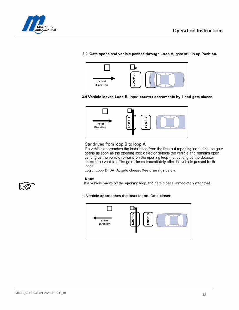
2.0 Gate opens and vehicle passes through Loop A, gate still in up Position. 3.0 Vehicle leaves Loop B, input counter decrements by 1 and gate closes.
Car drives from loop B to loop A If a vehicle approaches the installation from the free out (opening loop) side the gate opens as soon as the opening loop detector detects the vehicle and remains open as long as the vehicle remains on the opening loop (i.e. as long as the detector detects the vehicle). The gate closes immediately after the vehicle passed both loops. Logic: Loop B, BA, A, gate closes. See drawings below.
Note: If a vehicle backs off the opening loop, the gate closes immediately after that. 1. Vehicle approaches the installation. Gate closed.
LO
OP
B
LO
OP
A
TravelD irection
LO
OP
B
LO
OP
A
Trave lD irection
LOO
P B
LOO
P A
TravelDirection
Operation Instructions
MBE35_50 OPERATION MANUAL 2005_10 - 39 -
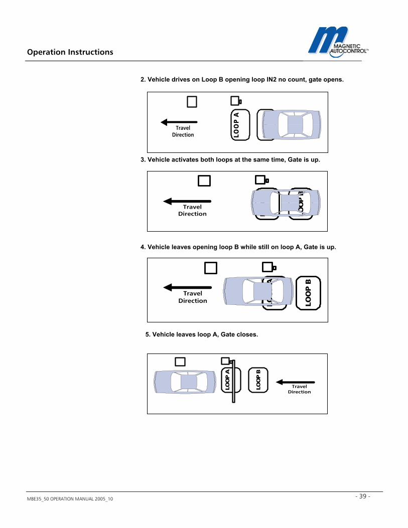
2. Vehicle drives on Loop B opening loop IN2 no count, gate opens.
3. Vehicle activates both loops at the same time, Gate is up.
4. Vehicle leaves opening loop B while still on loop A, Gate is up.
5. Vehicle leaves loop A, Gate closes.
LOO
P B
LOO
P A
TravelDirection
LOO
P B
LOO
P A
TravelDirection
LOO
P B
LOO
P A
TravelDirection
LOO
P B
LOO
P A
TravelDirection
Operation Instructions
MBE35_50 OPERATION MANUAL 2005_10 40
4.6.10 Operating Mode A Same as Mode 9 but with count reset timer 60 seconds.
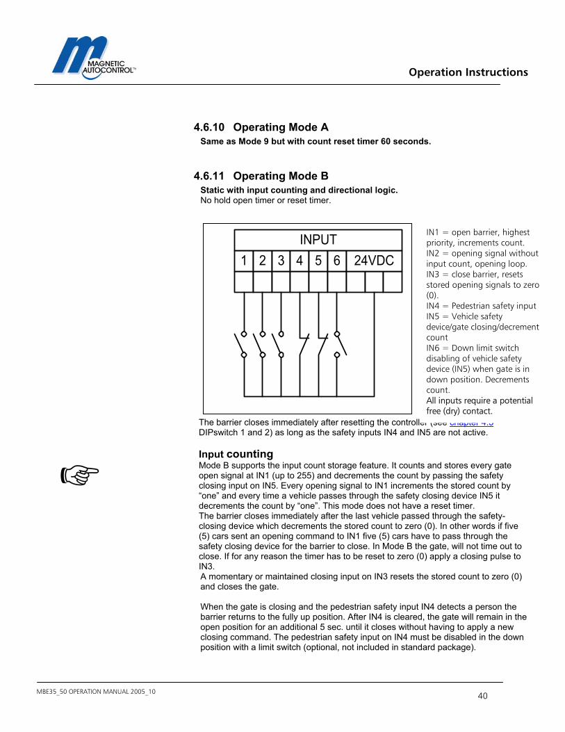
4.6.11 Operating Mode B Static with input counting and directional logic. No hold open timer or reset timer.
The barrier closes immediately after resetting the controller (see chapter 4.5 DIPswitch 1 and 2) as long as the safety inputs IN4 and IN5 are not active. Input counting Mode B supports the input count storage feature. It counts and stores every gate open signal at IN1 (up to 255) and decrements the count by passing the safety closing input on IN5. Every opening signal to IN1 increments the stored count by “one” and every time a vehicle passes through the safety closing device IN5 it decrements the count by “one”. This mode does not have a reset timer. The barrier closes immediately after the last vehicle passed through the safety-closing device which decrements the stored count to zero (0). In other words if five (5) cars sent an opening command to IN1 five (5) cars have to pass through the safety closing device for the barrier to close. In Mode B the gate, will not time out to close. If for any reason the timer has to be reset to zero (0) apply a closing pulse to IN3. A momentary or maintained closing input on IN3 resets the stored count to zero (0) and closes the gate. When the gate is closing and the pedestrian safety input IN4 detects a person the barrier returns to the fully up position. After IN4 is cleared, the gate will remain in the open position for an additional 5 sec. until it closes without having to apply a new closing command. The pedestrian safety input on IN4 must be disabled in the down position with a limit switch (optional, not included in standard package).
1 2 3 4 5 6 24VDCINPUT
IN1 = open barrier, highest priority, increments count. IN2 = opening signal without input count, opening loop. IN3 = close barrier, resets stored opening signals to zero (0). IN4 = Pedestrian safety input IN5 = Vehicle safety device/gate closing/decrement count IN6 = Down limit switch disabling of vehicle safety device (IN5) when gate is in down position. Decrements count. All inputs require a potential free (dry) contact.
Operation Instructions
MBE35_50 OPERATION MANUAL 2005_10 - 41 -
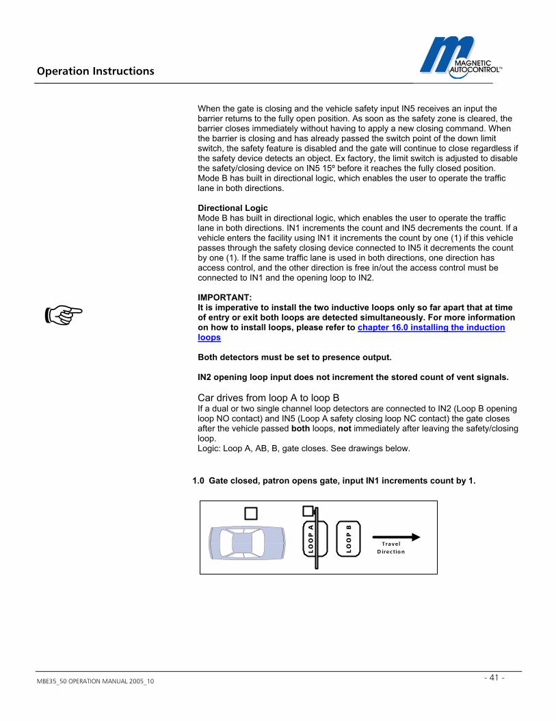
When the gate is closing and the vehicle safety input IN5 receives an input the barrier returns to the fully open position. As soon as the safety zone is cleared, the barrier closes immediately without having to apply a new closing command. When the barrier is closing and has already passed the switch point of the down limit switch, the safety feature is disabled and the gate will continue to close regardless if the safety device detects an object. Ex factory, the limit switch is adjusted to disable the safety/closing device on IN5 15º before it reaches the fully closed position. Mode B has built in directional logic, which enables the user to operate the traffic lane in both directions. Directional Logic Mode B has built in directional logic, which enables the user to operate the traffic lane in both directions. IN1 increments the count and IN5 decrements the count. If a vehicle enters the facility using IN1 it increments the count by one (1) if this vehicle passes through the safety closing device connected to IN5 it decrements the count by one (1). If the same traffic lane is used in both directions, one direction has access control, and the other direction is free in/out the access control must be connected to IN1 and the opening loop to IN2. IMPORTANT: It is imperative to install the two inductive loops only so far apart that at time of entry or exit both loops are detected simultaneously. For more information on how to install loops, please refer to chapter 16.0 installing the induction loops Both detectors must be set to presence output. IN2 opening loop input does not increment the stored count of vent signals. Car drives from loop A to loop B If a dual or two single channel loop detectors are connected to IN2 (Loop B opening loop NO contact) and IN5 (Loop A safety closing loop NC contact) the gate closes after the vehicle passed both loops, not immediately after leaving the safety/closing loop. Logic: Loop A, AB, B, gate closes. See drawings below.
1.0 Gate closed, patron opens gate, input IN1 increments count by 1.
LO
OP
B
LO
OP
A
TravelD irection
Operation Instructions
MBE35_50 OPERATION MANUAL 2005_10 42
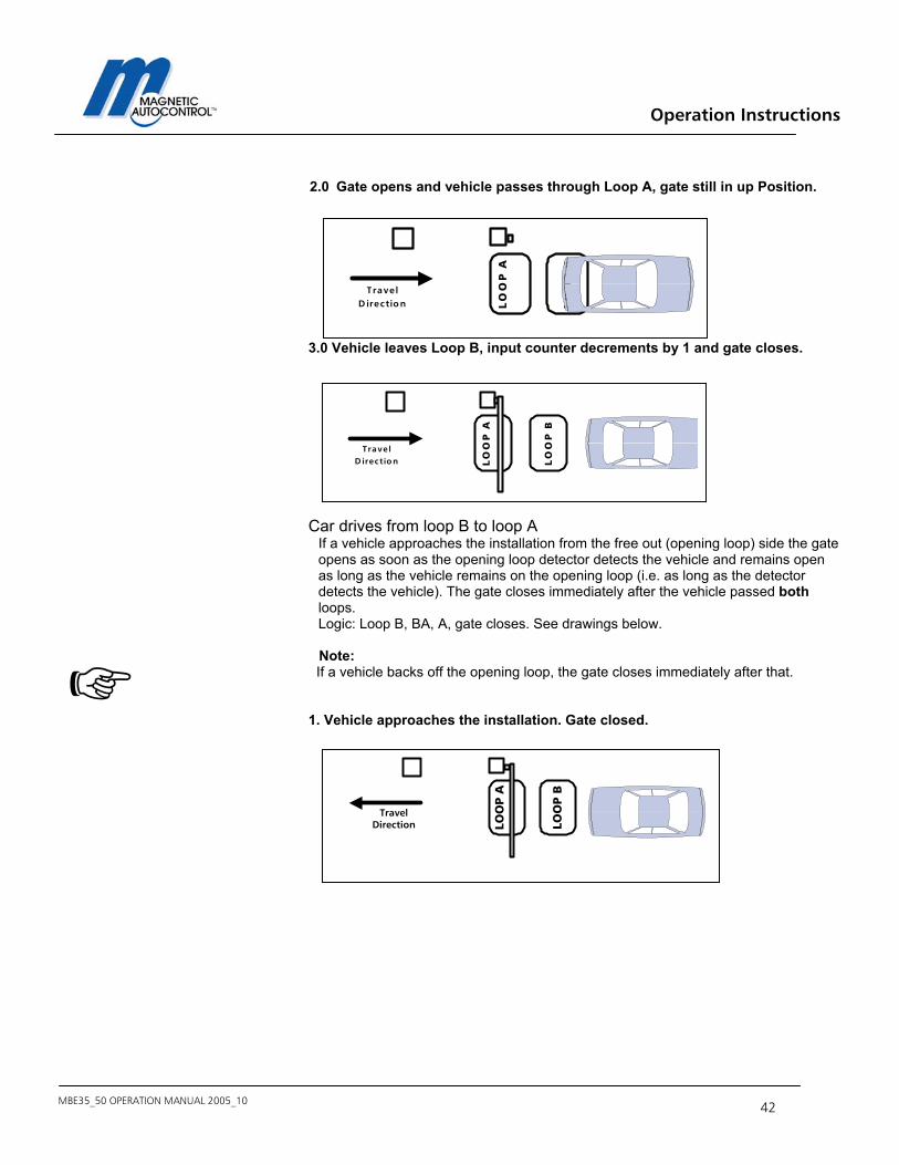
2.0 Gate opens and vehicle passes through Loop A, gate still in up Position. 3.0 Vehicle leaves Loop B, input counter decrements by 1 and gate closes.
Car drives from loop B to loop A
If a vehicle approaches the installation from the free out (opening loop) side the gate opens as soon as the opening loop detector detects the vehicle and remains open as long as the vehicle remains on the opening loop (i.e. as long as the detector detects the vehicle). The gate closes immediately after the vehicle passed both loops. Logic: Loop B, BA, A, gate closes. See drawings below.
Note: If a vehicle backs off the opening loop, the gate closes immediately after that. 1. Vehicle approaches the installation. Gate closed.
LO
OP
B
LO
OP
A
TravelD irection
LO
OP
B
LO
OP
A
Trave lD irection
LOO
P B
LOO
P A
TravelDirection

Operation Instructions
MBE35_50 OPERATION MANUAL 2005_10 - 43 -
2. Vehicle drives on Loop B opening loop IN2 no count, gate opens.
3. Vehicle activates both loops at the same time, Gate is up.
4. Vehicle leaves opening loop B while still on loop A, Gate is up.
5. Vehicle leaves loop A, Gate closes.
LOO
P B
LOO
P A
TravelDirection
LOO
P B
LOO
P A
TravelDirection
LOO
P B
LOO
P A
TravelDirection
LOO
P B
LOO
P A
TravelDirection
Operation Instructions
MBE35_50 OPERATION MANUAL 2005_10 44
5.0 Installing the Induction Loops
5.1 General induction loop functionality The Loop detectors operate on the principle of inductance. The detector monitors an insulated electrical wire, placed on or below the road surface (LOOP). Any metallic object, such as a car, which passes through the field will absorb electromagnetic energy and simultaneously decrease the inductance and increase the resonant frequency of the loop. For most conventional installations, when the inductance or frequency changes beyond a preset threshold in the detector electronics, the detector indicates that a vehicle has been detected. Note: Only metallic objects can be detected. The loop frequency change depends on the size and form of the to be monitored object (i.e. car) not on the material mass, which does not influence the loop. The micro controller system self adjusts to the connected loop. Many factors determine loop inductance, including wire size, wire length, the number of turns, lead length, and insulation. Changes in loop inductance due to temperature or aging are automatically compensated. Detectors with multiple channels (i.e. dual channel) are monitored using the MULTIPLEX METHOD, which eliminates the interference (cross-talk) between the loops connected to this detector.
5.2 Loop Inductance
5.2.1 Inductance
Inductance is the resistance to the change of current flow. When a current is applied to a conductor (wire), a magnetic field is formed around the conductor (wire). If the current source is removed, the magnetic field collapses into the wire trying to maintain the current flow. By winding several turns of the wire into a coil, the magnetic field is intensified which increases the inductance. The loop inductance can be measured with an inductivity meter. The unit of measurements is the Henry (h). The inductance depends on the loop perimeter and number of turns. A bigger loop with more turns has a higher Inductance.
Operation Instructions
MBE35_50 OPERATION MANUAL 2005_10 - 45 -
5.2.2 Vehicle detection When a vehicle enters the loop, the body and frame provide a conductive path for the magnetic field; causing a loading effect, which in turn causes the loop inductance to decrease. The decreased inductance causes the resonant frequency to increase from the nominal value. If the frequency change exceeds the threshold set by the sensitivity setting, the detector module will output a detect signal. There has been a misconception that an inductive loop requires a mass of metal for detection. Placing a single wire around the perimeter of the loop and shorting the ends together will quickly disprove the misconception. The single wire forming a shorted turn provides a current path for the magnetic field; thus causing a loading effect similar to that of a vehicle. The shorted turn effect of the single wire coil in the proximity of the loop acts much like a shorted turn secondary of a transformer.
5.2.3 Wire turns required for loops The Inductive loop detectors will tune from 70 µH to 500 µH (µH = micro Henry). It is preferable that the loop and lead-in have a minimum of approximately 70 µH for stability. The loop inductance should be equal to or greater than the lead-in inductance. If the inductance of the loop exceeds the requirements above, a proper functioning of the detector cannot be guaranteed. The loop inductance also influences the loop sensitivity. The best results are between 100 and 300 µH.
Operation Instructions
MBE35_50 OPERATION MANUAL 2005_10 46
5.2.4 Loop Inductance calculations
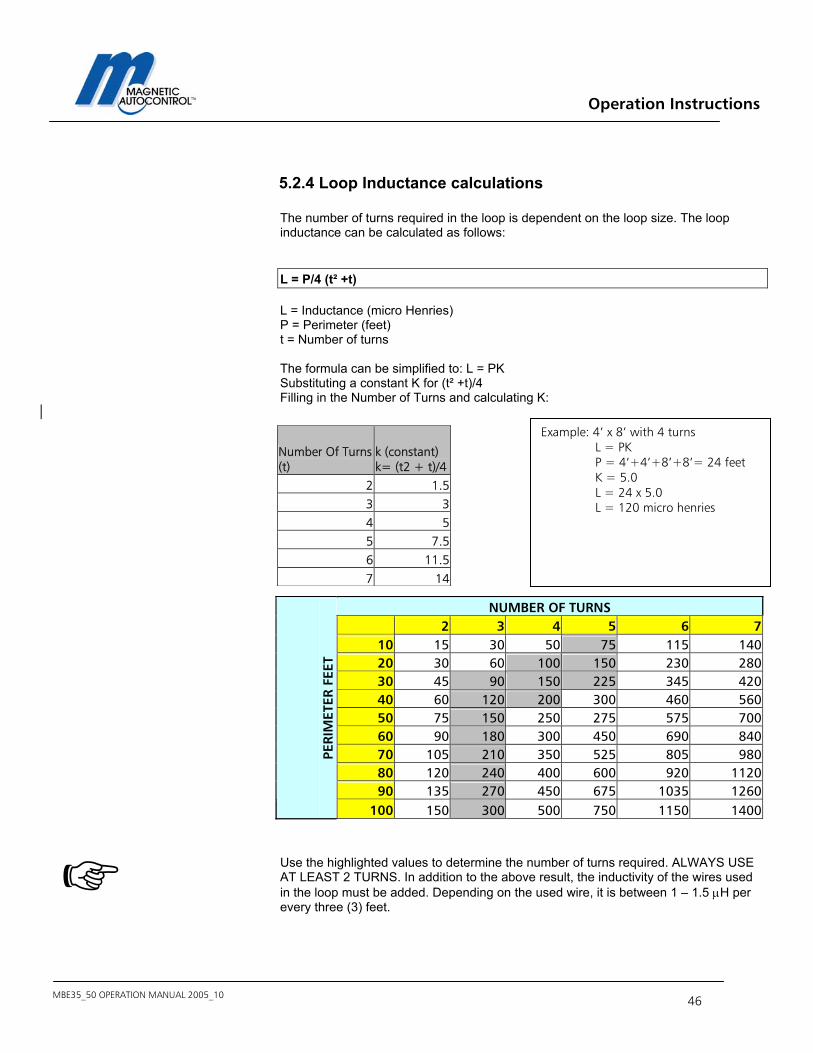
The number of turns required in the loop is dependent on the loop size. The loop inductance can be calculated as follows:
L = P/4 (t² +t)
L = Inductance (micro Henries) P = Perimeter (feet) t = Number of turns The formula can be simplified to: L = PK Substituting a constant K for (t² +t)/4 Filling in the Number of Turns and calculating K:
Note: Use the highlighted values to determine the number of turns required. ALWAYS USE AT LEAST 2 TURNS. In addition to the above result, the inductivity of the wires used in the loop must be added. Depending on the used wire, it is between 1 – 1.5 µH per every three (3) feet.
Example: 4’ x 8’ with 4 turns L = PK P = 4’+4’+8’+8’= 24 feet K = 5.0 L = 24 x 5.0 L = 120 micro henries
Number Of Turns(t)
k (constant) k= (t2 + t)/4
2 1.53 34 55 7.56 11.57 14
NUMBER OF TURNS 2 3 4 5 6 7
10 15 30 50 75 115 14020 30 60 100 150 230 28030 45 90 150 225 345 42040 60 120 200 300 460 56050 75 150 250 275 575 70060 90 180 300 450 690 84070 105 210 350 525 805 98080 120 240 400 600 920 112090 135 270 450 675 1035 1260
PERI
MET
ER F
EET
100 150 300 500 750 1150 1400
Operation Instructions
MBE35_50 OPERATION MANUAL 2005_10 - 47 -
5.3 Loop Detector Sensitivity
Most loop detectors come with multiple adjustable sensitivity settings. This means that only vehicles will be detected when the relative frequency change (difference between loop frequency with vehicle and without) is higher than the adjusted sensitivity. For example: If the sensitivity of a loop detector is adjusted to 0.05%, only vehicles that change the loop frequency by more than 0.05% will be detected. Note: To ensure a failsafe detection of vehicles, the value of the Relative Frequency Change should be at least 10 times higher than the adjusted loop sensitivity If the value is lower, it might not detect every vehicle (i.e. Pick-Up trucks). Wrong loop dimensioning or geometry, not enough windings, not enough clearance to metal objects within the road (i.e. steel reinforcement, sewer grill etc), can cause a low Relative Frequency Change value.
5.4 Installing an Induction Loop
5.4.1 Usage of Pre-manufactured Loops
Any pre-manufactured (formed) loop can be used as long they meet our requirements explained in this manual. Please refer to loop manufacturers Installation Instructions.
5.4.2 Self-Made Loops A loop can be manufactured from a single AWG 14-18 stranded XLPE insulated wire rated at 600V. The insulation type XLPE (cross-linked polyethylene) is highly recommended due to its higher quality insulation and higher resistance to abrasion, heating oil and gasoline. The wire gauge is not important to the operation of the loop detector but the wire should maintain its integrity under the pavement stress. Because asphalt is more flexible than concrete it is recommended that, a heavier gauge wire is used for loop installations in asphalt. The inductance of the loop shall be between 70 and 500 µH, which is usually achieved by having three to five turns in the coil. The loop resistance should be lower then 2Ω. The loop resistance should be measured after installing the loop but before sealing. The Loop Insulation Resistance must be measured to earth ground. The Insulation Resistance against earth ground must be a minimum of 5 MΩ at 500 Volts. If this is not the case, the loop insulation might be damaged. (See chapter 16.2 Loop Inductance). The temperature of the sealing must be below the temperature of the wire insulation.
Operation Instructions
MBE35_50 OPERATION MANUAL 2005_10 48
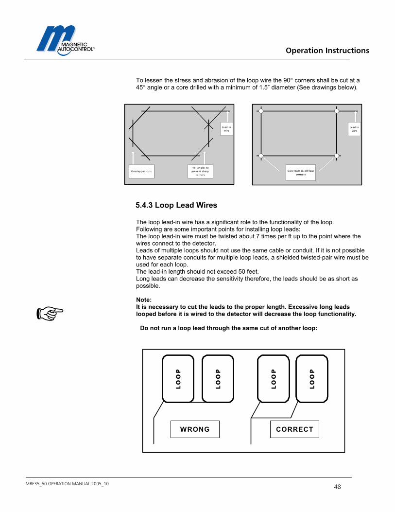
To lessen the stress and abrasion of the loop wire the 90° corners shall be cut at a 45° angle or a core drilled with a minimum of 1.5” diameter (See drawings below).
5.4.3 Loop Lead Wires
The loop lead-in wire has a significant role to the functionality of the loop. Following are some important points for installing loop leads: The loop lead-in wire must be twisted about 7 times per ft up to the point where the wires connect to the detector. Leads of multiple loops should not use the same cable or conduit. If it is not possible to have separate conduits for multiple loop leads, a shielded twisted-pair wire must be used for each loop. The lead-in length should not exceed 50 feet. Long leads can decrease the sensitivity therefore, the leads should be as short as possible. Note: It is necessary to cut the leads to the proper length. Excessive long leads looped before it is wired to the detector will decrease the loop functionality.
Do not run a loop lead through the same cut of another loop:
Overlapped cuts 45° angles toprevent sharp
corners
Lead-inwire
Lead-inwire
Core hole in all fourcorners
L
OO
P
LO
OP
LO
OP
WRONG CORRECT
LO
OP
Operation Instructions
MBE35_50 OPERATION MANUAL 2005_10 - 49 -
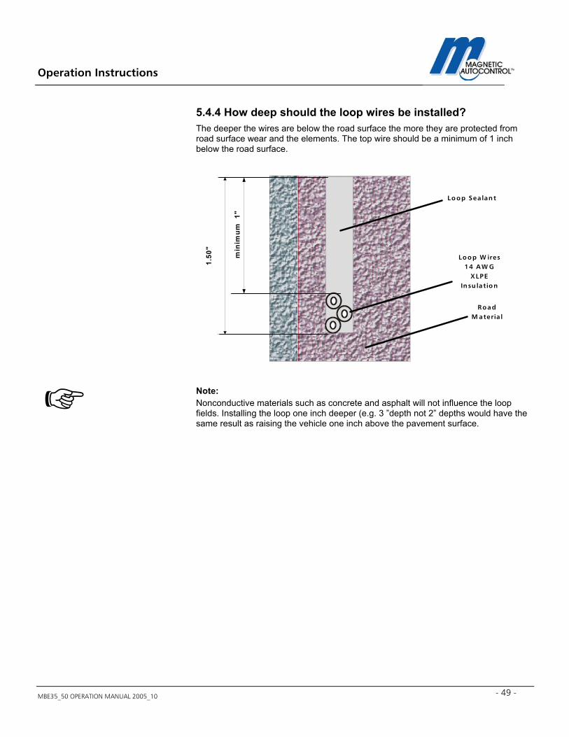
5.4.4 How deep should the loop wires be installed? The deeper the wires are below the road surface the more they are protected from road surface wear and the elements. The top wire should be a minimum of 1 inch below the road surface. Note: Nonconductive materials such as concrete and asphalt will not influence the loop fields. Installing the loop one inch deeper (e.g. 3 ”depth not 2” depths would have the same result as raising the vehicle one inch above the pavement surface.
Loop Sea lant
RoadM ateria l
Loop W ires14 A W G
XLPEInsu lation
1.50
"
min
imum
1"
Operation Instructions
MBE35_50 OPERATION MANUAL 2005_10 50
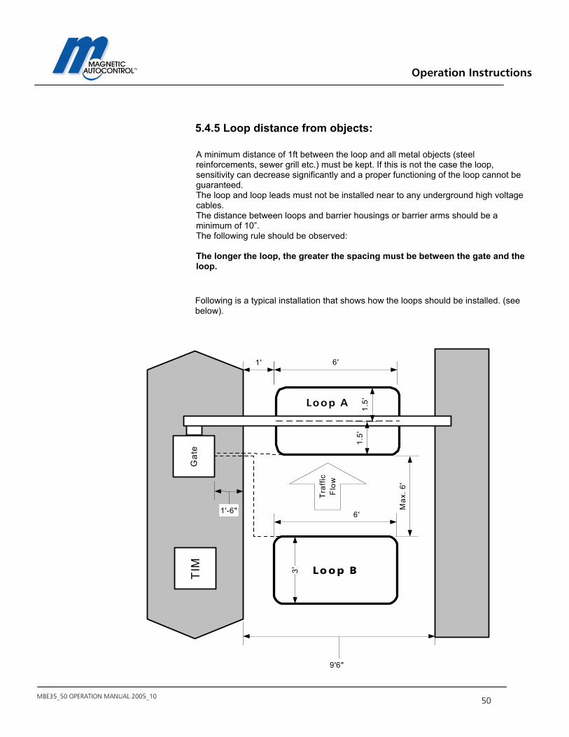
5.4.5 Loop distance from objects: A minimum distance of 1ft between the loop and all metal objects (steel reinforcements, sewer grill etc.) must be kept. If this is not the case the loop, sensitivity can decrease significantly and a proper functioning of the loop cannot be guaranteed. The loop and loop leads must not be installed near to any underground high voltage cables. The distance between loops and barrier housings or barrier arms should be a minimum of 10”. The following rule should be observed: The longer the loop, the greater the spacing must be between the gate and the loop. Following is a typical installation that shows how the loops should be installed. (see below).
TIM Lo o p B
Loop A
1.5'
1.5'
6'
3'
6'
Max
. 6'
1'
9'6"
Gat
e
Tra
ffic
Flo
w
1'-6"
Operation Instructions
MBE35_50 OPERATION MANUAL 2005_10 - 51 -
6.0 Commissioning
6.1 Commissioning procedure Once the barrier has been installed, the barrier boom attached and all electrical wiring work (including the installation of the induction loops) have been completed, according to the instructions; the barrier can be put into operation. To avoid the risk of injury and damage arising from any unintentional barrier movements during initial operations, all persons, and objects should be kept clear of the barrier.
6.2 Setting up the controller Note: Ex factory, the barrier comes in operating mode 5 and all DIP-Switches in the OFF position. Please read Chapter 4.0 Controller for controller setup.
6.3 Standard Configuration: Following are the standard controller configuration ex-factory: Operating Mode: 5 see chapter 4.6.5 DIP-Switch 1 OFF see chapter 4.5 DIP-Switch 2 OFF see chapter 4.5 DIP-Switch 3 OFF see chapter 4.5 DIP-Switch 4 OFF see chapter 4.5 DIP-Switch 5 OFF see chapter 4.5 DIP-Switch 6 OFF see chapter 4.5 DIP-Switch 7 OFF see chapter 4.5 DIP-Switch 8 OFF see chapter 4.5 Note: If your installation requires different setting, please follow the instructions in the corresponding chapters.
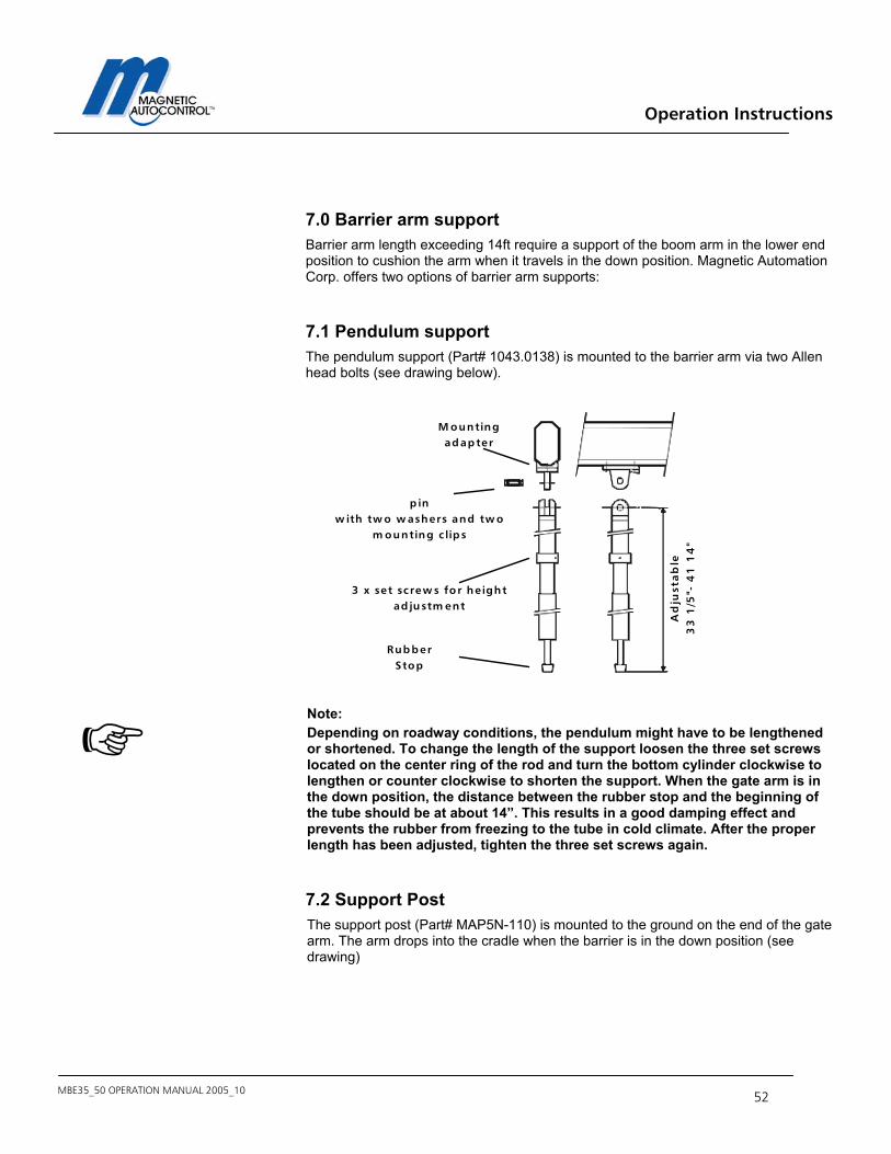
Operation Instructions
MBE35_50 OPERATION MANUAL 2005_10 52
7.0 Barrier arm support Barrier arm length exceeding 14ft require a support of the boom arm in the lower end position to cushion the arm when it travels in the down position. Magnetic Automation Corp. offers two options of barrier arm supports:
7.1 Pendulum support The pendulum support (Part# 1043.0138) is mounted to the barrier arm via two Allen head bolts (see drawing below).
Note: Depending on roadway conditions, the pendulum might have to be lengthened or shortened. To change the length of the support loosen the three set screws located on the center ring of the rod and turn the bottom cylinder clockwise to lengthen or counter clockwise to shorten the support. When the gate arm is in the down position, the distance between the rubber stop and the beginning of the tube should be at about 14”. This results in a good damping effect and prevents the rubber from freezing to the tube in cold climate. After the proper length has been adjusted, tighten the three set screws again.
7.2 Support Post The support post (Part# MAP5N-110) is mounted to the ground on the end of the gate arm. The arm drops into the cradle when the barrier is in the down position (see drawing)
M ountingadapter
p inw ith tw o w ashers and tw o
m ounting c lips
3 x set screw s for he ightad justm ent
Ad
just
ab
le3
3 1
/5"-
41
14
"
RubberStop

Operation Instructions
MBE35_50 OPERATION MANUAL 2005_10 - 53 -
Note: The height of the support post can be adjusted to compensate differences in height between the barrier and the support post foundation.
Crad lew ith foam
pad
Ad justm ent:Loosen the tw oM 6 lock nuts.
The he ight canbe ad justet
+ /- 3 /4 "
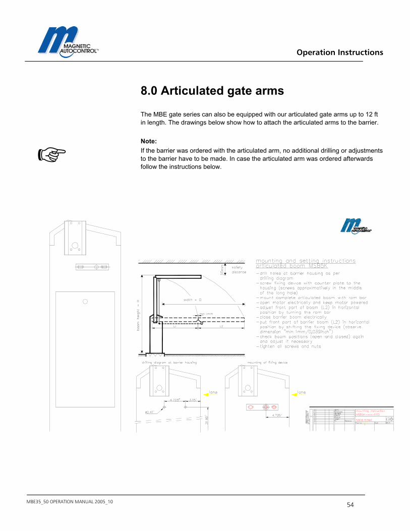
Operation Instructions
MBE35_50 OPERATION MANUAL 2005_10 54
8.0 Articulated gate arms The MBE gate series can also be equipped with our articulated gate arms up to 12 ft in length. The drawings below show how to attach the articulated arms to the barrier. Note: If the barrier was ordered with the articulated arm, no additional drilling or adjustments to the barrier have to be made. In case the articulated arm was ordered afterwards follow the instructions below.

Operation Instructions
MBE35_50 OPERATION MANUAL 2005_10 - 55 -
9.0 Technical Data 9.1 MAGSTOP Barriers MBE35 MBE50 Max. Boom length 12FT octagonal 15FT Opening/closing time 2.3/2.8 sec 4.6/4.9 sec Power consumption 65 W 65 W Housing Zinc-plated sheet
steel color powder coated.(Stainless steel optional)
Zinc-plated sheet steel color powder coated.(Stainless steel optional)
Housing dimensions (W x D x H)
12” x 14”x 41” 12” x 14”x 41”
Foundation base frame
Stainless steel Stainless steel
Weight (without arm) 145 lbs. 145 lbs. Operating temp. Range (Ambient)
-30°F TO +140°F -30°F TO +140°F
Drive Unit Torque motor Torque motor
10. Maintenance The MBE35/50 series barrier gates are designed for a long lifetime with only a minimum of maintenance required. To guarantee the greatest available equipment uptime and maximize the lifetime of the MIB30/40 series barriers please follow the prescribed maintenance schedules. Use the Maintenance Service Record, located on page 98, to keep track of your maintenance and upkeep activities on the MIB series barrier models.
10.1 Changing the Rubber End Stop The MIB* series barrier gates are equipped with two (2) rubber end stops to absorb the shock generated by the moving gate hitting the end positions. Those rubber end stops need to be replaced once per year or after one million cycles whatever comes first.
10.2 Checking the Exterior of Cabinet Inspect the housing for vehicular damage every six months.
Operation Instructions
MBE35_50 OPERATION MANUAL 2005_10 56
10.3 Check the barrier arm and the attachment kit Inspect the barrier arm for physical damage and check if the barrier arm attachment kit is used properly and all parts are in place and tight. Perform this inspection every six months.
10.4 Checking the Loop Detectors and Loop Wires Check the frequencies of the loops every six months. The loop wires should be replaced approximately every four years or as needed. Check the loop sealant every year for cracks or peeling. Replace if needed.
10.5 Check safety signage Inspect for proper attachment of all safety related signage such as Gate Cabinet and barrier arm safety sticker.
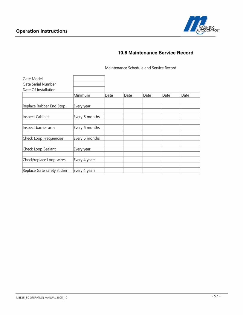
Operation Instructions
MBE35_50 OPERATION MANUAL 2005_10 - 57 -
10.6 Maintenance Service Record
Notes:
Maintenance Schedule and Service Record Gate Model Gate Serial Number Date Of Installation Minimum Date Date Date Date Date Replace Rubber End Stop Every year Inspect Cabinet Every 6 months Inspect barrier arm Every 6 months Check Loop Frequencies Every 6 months Check Loop Sealant Every year Check/replace Loop wires Every 4 years Replace Gate safety sticker Every 4 years

Operation Instructions
MBE35_50 OPERATION MANUAL 2005_10 58
Magnetic Automation Corp. 3160 Murrell Road Rockledge, FL 32955 Phone: 321-635-8585 Fax: 321-635-9449 E-Mail: [email protected] Web: http://www.ac-magnetic.com
For Sales and Service, Contact Your Local Magnetic Automation Corp. Distributor:
2001 Magnetic Automation Corp. Subject to design and/or appearance modifications, which are production standards at the time of shipment