Embed Size (px)
Citation preview

Operating Instructions
Device platform EAGLE
ET-xx6-A-*
SERIES 300 Operator Interfaces SERIES 400 Panel PC
SERIES 500 Thin Clients
(valid for HW Revision 3)
R. STAHL HMI Systems GmbH Adolf-Grimme-Allee 8
D 50829 Köln
HW-Rev. ET-xx6-A-FX: 03.00.12 HW-Rev. ET-xx6-A-TX: 03.00.22 HW-Rev. ET-xx6-A-FX-BT: 03.00.16 HW-Rev. ET-xx6-A-TX-BT: 03.00.26 HW-Rev. ET-3x6-A-FX-BS: 03.00.17 HW-Rev. ET-3x6-A-TX-BS: 03.00.27 Operating Instructions Version: 03.00.34 Issue date: 27.11.2019
Operating Instructions ET-xx6-A Disclaimer
Page 2 of 60 R. STAHL HMI Systems GmbH / OI_ET_xx6_A_en_V_03_00_34.docx / 27.11.2019
Disclaimer
Publisher and copyright holder: R. STAHL HMI Systems GmbH Adolf-Grimme-Allee 8 D 50829 Köln Phone: (switchboard) +49 (0) 221 76 806 - 1000 (hotline) - 5000 Fax: - 4100 E-mail: (switchboard) [email protected] (hotline) [email protected]
• All rights reserved. • This document may not be reproduced in whole or in part except with the written consent
of the publisher. • This document may be subject to change without notice.
Any warranty claims are limited to the right to demand amendments. Liability for any damage that might result from the content of this description or all other documentation is limited to clear cases of premeditation. We reserve the right to change our products and their specifications at any time, provided it is in the interest of technical progress. The information in the current manual (in the internet and on CD / DVD / USB stick) or in the operating instructions included with the HMI device applies. Trademarks The terms and names used in this document are registered trademarks and / or products of the companies in question. Copyright © 2019 R. STAHL HMI Systems GmbH. Subject to alterations.
Operating Instructions ET-xx6-A Specific markings
R. STAHL HMI Systems GmbH / OI_ET_xx6_A_en_V_03_00_34.docx / 27.11.2019 Page 3 of 60
Specific markings
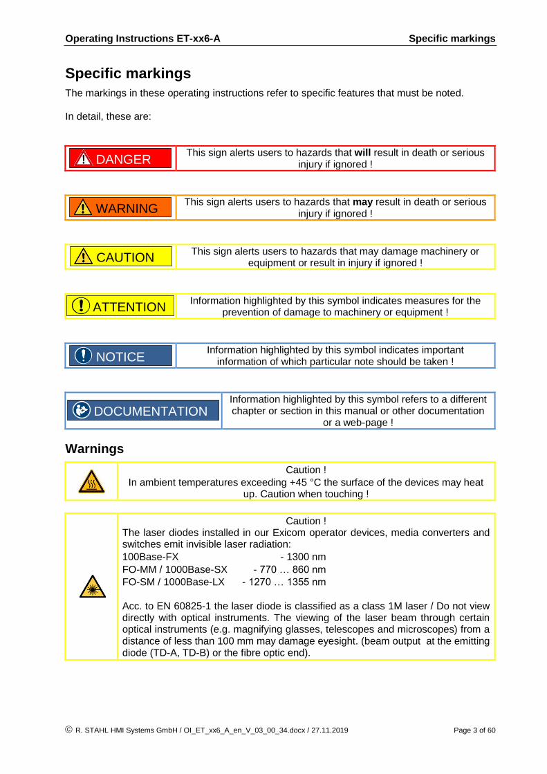
The markings in these operating instructions refer to specific features that must be noted. In detail, these are:
This sign alerts users to hazards that will result in death or serious injury if ignored !
This sign alerts users to hazards that may result in death or serious injury if ignored !
This sign alerts users to hazards that may damage machinery or equipment or result in injury if ignored !
Information highlighted by this symbol indicates measures for the prevention of damage to machinery or equipment !
Information highlighted by this symbol indicates important information of which particular note should be taken !
Information highlighted by this symbol refers to a different chapter or section in this manual or other documentation
or a web-page !
Warnings
Caution !
In ambient temperatures exceeding +45 °C the surface of the devices may heat up. Caution when touching !
Caution ! The laser diodes installed in our Exicom operator devices, media converters and switches emit invisible laser radiation:
100Base-FX - 1300 nm
FO-MM / 1000Base-SX - 770 … 860 nm
FO-SM / 1000Base-LX - 1270 … 1355 nm
Acc. to EN 60825-1 the laser diode is classified as a class 1M laser / Do not view directly with optical instruments. The viewing of the laser beam through certain optical instruments (e.g. magnifying glasses, telescopes and microscopes) from a distance of less than 100 mm may damage eyesight. (beam output at the emitting diode (TD-A, TD-B) or the fibre optic end).
DANGER
WARNING
CAUTION
DOCUMENTATION
NOTICE
ATTENTION
Operating Instructions ET-xx6-A Table of contents
Page 4 of 60 R. STAHL HMI Systems GmbH / OI_ET_xx6_A_en_V_03_00_34.docx / 27.11.2019
Table of contents
Description Page
Disclaimer 2
Specific markings 3
Warnings 3
Table of contents 4
1 Preface 7
2 Device function 7
2.1 Image sticking 7
2.2 Processor types 7
2.3 Activation pressure touchscreen 7
2.4 ET-3x6-A-* (SERIES 300 Operator Interfaces) 8
2.5 ET-4x6-A-* (SERIES 400 Panel PC) 8
2.6 ET-5x6-A-* (SERIES 500 Thin Clients) 8
2.7 Overview hardware revision ET-xx6 8
3 Technical Data 9
3.1 Additionally for ET-3x6-A-* (Operator Interfaces) 12
3.1.1 All devices up to hardware revision 03.00.x2 12
3.1.2 All devices starting from hardware revision 03.00.x5 12
3.1.3 All devices starting from hardware revision 03.00.x7 12
3.2 Additionally for ET-4x6-A-* (Panel PC) 12
3.2.1 All devices up to hardware revision 03.00.x2 12
3.2.2 All devices starting from hardware revision 03.00.x4 12
3.2.3 All devices starting from hardware revision 03.00.x6 12
3.3 Additionally for ET-5x6-A-* (Thin Clients) 13
3.3.1 All devices up to hardware revision 03.00.x2 13
3.3.2 All devices starting from hardware revision 03.00.x4 13
3.3.3 All devices starting from hardware revision 03.00.x6 13
4 Conformity to standards 13
5 Certificates 14
5.1 ATEX 15
5.2 IECEx 15
5.3 EAC (TR) 15
5.4 PESO 15
5.5 KGS 15
5.6 NEC / UL 15
5.7 CEC / CSA 16
5.8 INMETRO 16
5.9 CNEX 16
5.10 DNV / GL 16
5.11 ABS 16
5.12 LR 16
6 Marking 17
7 Power supply 18
7.1 HMI devices 18
7.1.1 HMI device terminals 18

Operating Instructions ET-xx6-A Table of contents
R. STAHL HMI Systems GmbH / OI_ET_xx6_A_en_V_03_00_34.docx / 27.11.2019 Page 5 of 60
7.1.1.1 Tightening torque 18
8 Permitted maximum values 19
8.1 External, non-intrinsically safe circuits 19
8.2 External inherently safe optical interface 19
8.3 External intrinsically safe circuits 20
9 Type code 23
9.1 Certificate 23
9.2 Variants 24
9.2.1 ET-3x6-A (Operator Interfaces) 24
9.2.2 ET-3x6-A-*-BS (Operator Interfaces) 24
9.2.3 ET-4x6-A (Panel PC) 25
9.2.4 ET-4x6-A-*-BT (Panel PC) 26
9.2.5 ET-5x6-A (Thin Client) 27
9.2.6 ET-5x6-A-*-BT (Thin Client) 27
10 Safety Advice 28
10.1 Installation and operation 28
10.2 Cautionary notes 29
10.3 Special conditions 29
11 Installation 30
11.1 General information 30
11.2 ET-xx6-A-* 30
11.2.1 HMI device Installation in housings type of protection "e" or "t" 30
11.2.2 Cable glands 31
11.3 Usage of the USB-interfaces 32
11.3.1 Usage of USB Memory-Sticks 32
11.3.2 Usage of external USB devices 32
11.4 USB interfaces 33
11.4.1 I.S. USB interfaces USB0, USB2 33
11.4.2 Ex e USB interfaces USB1, USB3 33
11.4.2.1 Connection variations for Ex e USB interfaces 33
11.4.2.2 Connection terminal with protection type "e" (IEC/EN 60079-7) 34
12 Assembly and disassembly 35
12.1 General information 35
12.2 Cut-out ET-xx6-A-* 35
13 Operation 36
13.1 General information 36
13.2 Connections 36
13.2.1 Dip switch settings S3 and S4 38
13.2.2 Status LEDs 38
13.2.2.1 LEDs 38
13.3 Connection of Readers 40
13.3.1 Type RSi1 connection version 1 40
13.3.2 Type RSi1 connection version 2 40
14 Maintenance, service 41
14.1 Damaged sealing 41
14.2 Servicing 41
14.3 Saving data with ET-3x6-A-* 41

Operating Instructions ET-xx6-A Table of contents
Page 6 of 60 R. STAHL HMI Systems GmbH / OI_ET_xx6_A_en_V_03_00_34.docx / 27.11.2019
14.4 Time function 42
15 Troubleshooting 42
16 Disposal 42
16.1 RoHS directive 2011/65/EC 42
16.1.1 China RoHS labelling 42
17 General information 43
17.1 Touch driver 43
17.2 Keyboard features 43
17.3 ET-4x6-A-* (Panel PC) 44
17.3.1 Up to Windows 7 operating systems 44
17.3.1.1 Licensing issues 44
17.3.1.2 Note on Windows Embedded operating systems 44
17.3.2 Windows® 10 IoT Enterprise 2016 LTSB operating system 44
17.3.2.1 Recovery 45
17.3.2.2 Company-specific Windows installations 45
17.3.3 Initial start-up 45
17.3.4 Recovery Stick 45
17.3.5 Back-up 45
17.3.6 Switching off / closing down 46
17.3.7 Data loss 46
17.4 Defective pixels 47
17.4.1 Terminology 47
17.4.2 Display specification 48
18 Certification Drawing NEC / UL 49
19 Control Drawing 50
19.1 NEC / UL 50
19.2 CEC / CSA 53
20 Declaration of EC conformity 56
20.1 RCM 57
21 Release notes 59

Operating Instructions ET-xx6-A Preface
R. STAHL HMI Systems GmbH / OI_ET_xx6_A_en_V_03_00_34.docx / 27.11.2019 Page 7 of 60
1 Preface
These Operating Instructions contain all aspects relevant to explosion protection for the ET-xx6-A-* HMI devices (SERIES 300 Operator Interfaces – EAGLE, SERIES 400 Open HMI – Panel PC´s and SERIES 500 Thin Clients). They also contain information on the connection and installation of these devices. These Operating Instructions contain a joint description of all three product lines: Operator Interfaces, Panel PC´s and Thin Clients. Any differences between the three product lines will be explicitly mentioned and dealt with. As a rule, though, the information contained in these Operating Instructions applies to all models of the ET-xx6-A-* series. The ET-xx6-A-* HMI devices with display sizes of 26 cm / 10.4", 38 cm / 15" and 48 cm / 19" will be available in Hardware Revision 3.
All data relevant to explosion protection from the EC-type examination certificate were copied into these operating instructions.
For the correct operation of all associated components please note, in addition to these operating instructions, all other operating instructions enclosed in this delivery as well as the operating instructions of the additional equipment to be connected !
Please note that all certificates of the HMI devices can be found in a separate document (CE_ET-xx6-A). You can find this document in the internet at r-stahl.com or request it from R. STAHL HMI Systems GmbH.
For more information on the HMIs please also refer to the Manual (available as online manual on r-stahl.com).
2 Device function
The ET-xx6-A-* HMI devices are explosion-proof equipment for installation in hazardous areas and can be installed in zones 1, 2, 21 and 22 according to ATEX directive. All devices have a modular structure, which makes changes and maintenance easy. They can be integrated into control cabinets or panels, etc.
2.1 Image sticking
Continuous displaying fixed pattern may include image sticking. It’s recommended to use screen saver or moving content periodically if fixed pattern is displayed on the screen.
2.2 Processor types
All devices are fitted with modern, powerful processors. Depending on the type of application, different processor types are used for the HMI devices (see Technical Data). Starting in 2016, a new Intel® Atom™ processor type of the Bay Trail (BT / BS) platform will gradually replace all previous processor types in the HMI devices. This new processor type processes data four times as fast as the previous processors.
2.3 Activation pressure touchscreen
To prevent damage to the touchscreen, activation pressure on the screen must be very low (0.1 to max. 1 N).
NOTICE
DOCUMENTATION

Operating Instructions ET-xx6-A Device function
Page 8 of 60 R. STAHL HMI Systems GmbH / OI_ET_xx6_A_en_V_03_00_34.docx / 27.11.2019
2.4 ET-3x6-A-* (SERIES 300 Operator Interfaces)
The ET-3x6-A-* operator interfaces have been designed for the Visualization of medium-sized automation tasks, operation as built-in device and tankfarm application in hazardous areas. The ET-3x6-A-* operating stations have been designed to run with a proprietary operating system, making them highly secure against external manipulation. Users operate the device via the membrane keyboard integrated into the front plate and via the LCD display with touch screen. Communication with control and automation systems runs via the serial interfaces (RS-232 RS-422/485, Ethernet) connected in the "e"-area at the back of the devices. Various peripheral devices, such as barcode scanners, card readers, USB sticks and WLAN / Bluetooth modules can be connected via USB interfaces or optional fitted modules. With a wealth of functions, these HMI devices provide optimum visualization. Their active communication concept in combination with integrated functionality reduce the automation system workload.
2.5 ET-4x6-A-* (SERIES 400 Panel PC)
The ET-4x6-A-* devices are robust Panel PC´s for hazardous areas. With their pre-installed Windows operating system they are ready to run straight away. As a standard, all Panel PC´s are equipped with a touch screen and several interfaces and are based on the powerful Atom technology, making them the most powerful devices on the market.
2.6 ET-5x6-A-* (SERIES 500 Thin Clients)
The ET-5x6-A-* devices of the 500 SERIES can be integrated into modern networks as Thin Clients or with a KVM box via KVM-over-IP, thus providing ideal and flexible access options with central data administration. The ET-5x6-A-* device, which is used for operation and visualization, is located in the hazardous area, whereas the PC that is operated is located in the safe area. Each ERP / MES network can be accessed from each Thin Client via the IP address. The Thin Client system supports both modern technologies such as DVI and USB and older technologies such as VGA and PS/2.
2.7 Overview hardware revision ET-xx6
HW-Rev. Device type Technical changing Changing date
hardware OI
version OI date
03.00.1x ET-xx6-A-FX Approval Rev. 3, FX interface
25.05.2011 03.00.02 09.06.2011
03.00.2x ET-xx6-A-TX Approval Rev. 3, TX interface
03.00.x2 ET-xx6-A-* 5-wire touch 23.06.2014 03.00.15 03.09.2014
03.00.x3 ET-xx6-A-* Internal changes 29.09.2014 - -
03.00.x4 ET-xx6-A-* Bay Trail processor, quad core
10.02.2016 03.00.17 04.01.2016
03.00.x5 ET-3x6-A-*-BS-* Bay Trail processor, single core
08.05.2017 03.00.25 03.06.2017
03.00.x6 ET-xx6-A-* M.2 memory 14.06.2018 03.00.29 14.07.2018
03.00.x7 ET-3x6-A-*-BS-*
03.02.xx ET-xx6-A-*-RS2 Approval 2nd supplement with COM2 (X22)
21.11.2012 03.02.00 16.04.2013

Operating Instructions ET-xx6-A Technical Data
R. STAHL HMI Systems GmbH / OI_ET_xx6_A_en_V_03_00_34.docx / 27.11.2019 Page 9 of 60
3 Technical Data
Function / Equipment ET-306-A-* ET-406-A-*
ET-316-A-* ET-416-A-* ET-516-A-*
ET-336-A-* ET-436-A-*-(SR) ET-536-A-*-(SR)
ET-456-A-* ET-556-A-*
Display type TFT Color,
16,777,216 Colors
Display size 26 cm (10.4") 38 cm (15") 48 cm (19")
Resolution in pixels
ET-306-A-*
VGA 640 x 480
ET-406-A-*
SVGA 800 x 600
SVGA 800 x 600 XGA 1024 x 768 SXGA 1280 x 1024
Display Touchscreen on glass
Touchscreen *
Type TFT 5-wire analogue resistive
Type SR (Sunlight readable) - 5-wire analogue resistive
-
* Comment Under extreme environmental conditions (high humidity, temperature), bubbles can form on the touch surface in rare cases. This does not represent any functional restriction and affects
only the appearance.
Backlight LED background lighting
Service life of backlight at
+25 °C [+77 °F] 70,000 h
+55 °C [+131 °F] 35,000 h
Brightness
Type TFT VGA 450 cd/m² 350 cd/m² 350 cd/m²
SVGA 400 cd/m²
Type SR (Sunlight readable) - 1000 cd/m² -
Contrast
Type TFT 700:1 1000:1
Type SR (Sunlight readable) - 600:1 -
Touchscreen activation Low activation pressure (0.1 up to max. 1 N)
Touchscreen input method Finger, gloved finger or stylus
Touchscreen durability Polyester foil is easily scratched, with high pressure force the spacer dots could be damaged.
Touchscreen scratch hardness MoHS
-
Touchscreen scratch hardness pencil hardness test ISO 15184
3H
Touchscreen transmissivity / optics
Small milky effect due to the foil
Touchscreen surface contaminants
Unaffected
Touchscreen abrasive resistance 36 million times with a silicone rubber of R8 finger, hitting rate 250 g at 2 times per second
Keyboard Polyester membrane on aluminium plate (> 1 million actions)
Functional keys
Soft keys
Cursor keys
Alphanumeric keys
System keys
12
10
yes
12
14
12
no
no
no
no
8
no
no
no
no
8
no
no
no
no
Additional keyboard
Optional 100 mA max. power consumption
105 Keys
or
107 keys with integrated trackball / joystick
(variant with trackball / joystick not for ET-3x6-A-*)
Trackball / joystick Optional for ET-4x6-A-* and ET-5x6-A-*
Power supply Directly in the integrated Ex e connection box
Rated operational voltage DC 24 V
Voltage range DC 20.4 – 28.8 V
up from 100 GB data memory
21.6 – 28.8 V
Current consumption DC 1.2 A
Connections via screw terminals, 2.5 mm² (AWG14) green (Ex e) (connection X1)
Max. operating voltage Um 30 VDC
Operating Instructions ET-xx6-A Technical Data
Page 10 of 60 R. STAHL HMI Systems GmbH / OI_ET_xx6_A_en_V_03_00_34.docx / 27.11.2019
Function / Equipment ET-306-A-* ET-406-A-*
ET-316-A-* ET-416-A-* ET-516-A-*
ET-336-A-* ET-436-A-*-(SR) ET-536-A-*-(SR)
ET-456-A-* ET-556-A-*
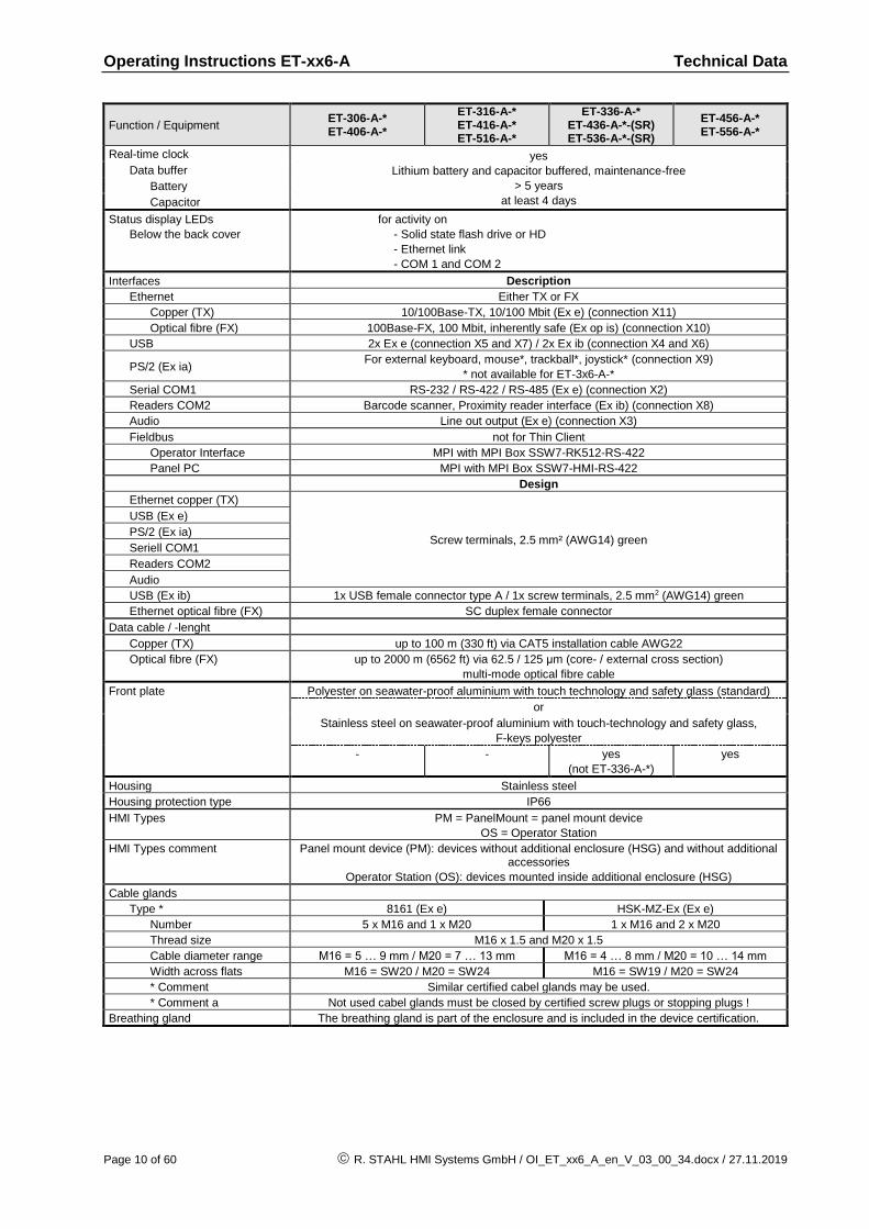
Real-time clock yes
Lithium battery and capacitor buffered, maintenance-free
> 5 years
at least 4 days
Data buffer
Battery
Capacitor
Status display LEDs
Below the back cover
for activity on
- Solid state flash drive or HD
- Ethernet link
- COM 1 and COM 2
Interfaces Description
Ethernet Either TX or FX
Copper (TX) 10/100Base-TX, 10/100 Mbit (Ex e) (connection X11)
Optical fibre (FX) 100Base-FX, 100 Mbit, inherently safe (Ex op is) (connection X10)
USB 2x Ex e (connection X5 and X7) / 2x Ex ib (connection X4 and X6)
PS/2 (Ex ia) For external keyboard, mouse*, trackball*, joystick* (connection X9)
* not available for ET-3x6-A-*
Serial COM1 RS-232 / RS-422 / RS-485 (Ex e) (connection X2)
Readers COM2 Barcode scanner, Proximity reader interface (Ex ib) (connection X8)
Audio Line out output (Ex e) (connection X3)
Fieldbus not for Thin Client
Operator Interface MPI with MPI Box SSW7-RK512-RS-422
Panel PC MPI with MPI Box SSW7-HMI-RS-422
Design
Ethernet copper (TX)
Screw terminals, 2.5 mm² (AWG14) green
USB (Ex e)
PS/2 (Ex ia)
Seriell COM1
Readers COM2
Audio
USB (Ex ib) 1x USB female connector type A / 1x screw terminals, 2.5 mm2 (AWG14) green
Ethernet optical fibre (FX) SC duplex female connector
Data cable / -lenght
Copper (TX) up to 100 m (330 ft) via CAT5 installation cable AWG22
Optical fibre (FX) up to 2000 m (6562 ft) via 62.5 / 125 μm (core- / external cross section)
multi-mode optical fibre cable
Front plate Polyester on seawater-proof aluminium with touch technology and safety glass (standard)
or
Stainless steel on seawater-proof aluminium with touch-technology and safety glass,
F-keys polyester
- - yes
(not ET-336-A-*)
yes
Housing Stainless steel
Housing protection type IP66
HMI Types PM = PanelMount = panel mount device
OS = Operator Station
HMI Types comment Panel mount device (PM): devices without additional enclosure (HSG) and without additional accessories
Operator Station (OS): devices mounted inside additional enclosure (HSG)
Cable glands
Type * 8161 (Ex e) HSK-MZ-Ex (Ex e)
Number 5 x M16 and 1 x M20 1 x M16 and 2 x M20
Thread size M16 x 1.5 and M20 x 1.5
Cable diameter range M16 = 5 … 9 mm / M20 = 7 … 13 mm M16 = 4 … 8 mm / M20 = 10 … 14 mm
Width across flats M16 = SW20 / M20 = SW24 M16 = SW19 / M20 = SW24
* Comment Similar certified cabel glands may be used.
* Comment a Not used cabel glands must be closed by certified screw plugs or stopping plugs !
Breathing gland The breathing gland is part of the enclosure and is included in the device certification.
Operating Instructions ET-xx6-A Technical Data
R. STAHL HMI Systems GmbH / OI_ET_xx6_A_en_V_03_00_34.docx / 27.11.2019 Page 11 of 60
Function / Equipment ET-306-A-* ET-406-A-*
ET-316-A-* ET-416-A-* ET-516-A-*
ET-336-A-* ET-436-A-*-(SR) ET-536-A-*-(SR)
ET-456-A-* ET-556-A-*
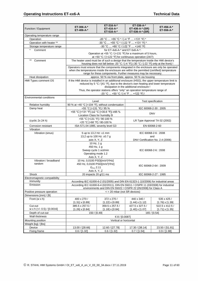
Operating temperature range
Operation -20 °C … +55 °C * / [-4 °F … +131 °F] *
Operation with heater ** -30 °C … +55 °C * / [-22 °F … +131 °F] *
Storage temperature range -30 °C … +60 °C / [-22 °F … +140 °F]
* Comment for ET-4x6-A-* and ET-5x6-A-*:
Operation at +55 °C / [+131 °F] for a maximum of 5 hours,
at +50 °C / [+122 °F] for continuous operation (24/7)
** Comment The heater used must be of such a design that the temperature inside the HMI device's housing does not fall below -20 °C / [-4 °F] (-30 °C / [-22 °F] only at the front) !
Operators must ensure that the components integrated in the enclosure are only be operated when the temperatures inside the enclosure are within the permitted (certified) temperature
range for these components. Further measures may be necessary.
Heat dissipation approx. 50 % via front plate, approx. 50 % via housing
HMI Types comment OS If the HMI device is installed in an additional enclosure (HSG), the upper temperature limit is reduced by 5 °C / [41 °F], due to the device's own heating and lower temperature
dissipation in the additional enclosure !
Thus, the operator stations offers "only" an operation temperature range of
-20 °C ... +50 °C / [-4 °F … +122 °F] !
Environmental conditions
Level Test specification
Relative humidity 90 % at +40 °C [+104 °F], without condensation -
Damp heat +55 °C [+131 °F] / 95 % IEC 60068-2-30 : 2005
+55 °C [+131 °F] (±2 °C [+35.6 °F]) ≥95 %
Location Class for humidity B DNV
(cyclic 2x 24 h) +55 °C [+131 °F] / 90-100 %
+20 °C [+68 °F] / 80-100 % LR Type Approval TA 02 (2002)
Corrosion resistant ISA-S71.04-1985, severity level G3 EN 60068-2-60
Vibration
Vibration (sinus) 5 up to 13.2 Hz: ±1 mm
13,2 up to 100 Hz: ±0.7 g
axis X, Y, Z
IEC 60068-2-6 : 2008
and
DNV Certification No. 2.4 (2006)
10 Hz, 1 g
450 Hz, 1 g
Sweep cycle 1 oct/min
Operating mode 1.2
Axis X, Y, Z
IEC 60068-2-6 : 2008
Vibration / broadband random
10 Hz, 0,0100 PSD[(m/s²)²/Hz]
450 Hz, 0,0100 PSD[(m/s²)²/Hz]
Grms 2.11
Axis X, Y, Z
IEC 60068-2-64 : 2009
Shock 20 impacts 20 g/11 ms IEC 60068-2-27 : 1995
Electromagnetic compatibility
Immunity According IEC 61000-6-2 (01/2005) and DIN EN 61323-1 (10/2006) for industrial areas
Emission According IEC 61000-6-4 (02/2011), DIN EN 55011 / CISPR 11 (03/2008) for industrial environments and DIN EN 55022 / CISPR 22 (05/2008) for Class A
Positive pressure operation < = 20 mbar (not SR devices)
Dimensions [mm] / [ft]
Front (w x h) 400 x 270 /
[1.31] x [0.89]
372 x 270 /
[1.22] x [0.89]
440 x 340 /
[1.44] x [1.12]
535 x 425 /
[1.76] x [1.39]
Cut-out w x h (+/- 0.5) / [0.0016]
385.5 x 257.5 /
[1.26] x [0.84]
359.5 x 257.5 /
[1.18] x [0.84]
427.5 x 327.5 /
[1.40] x [1.07]
522.5 x 412.5 /
[1.71] x [1.35]
Depth of cut-out 150 / [0.49] 165 / [0.54]
Wall thickness ≤ 8 / [0.0087]
Mounting position Vertical or horizontal
Weight [kg] / [lbs]
Device 13.00 / [28.66] 12.60 / [27.78] 17.30 / [38.14] 23.50 / [51.81]
Fixing frame 0.6 / [1.32] 0.6 / [1.32] 0.7 / [1.54] 0.9 / [1.98]
Operating Instructions ET-xx6-A Technical Data
Page 12 of 60 R. STAHL HMI Systems GmbH / OI_ET_xx6_A_en_V_03_00_34.docx / 27.11.2019
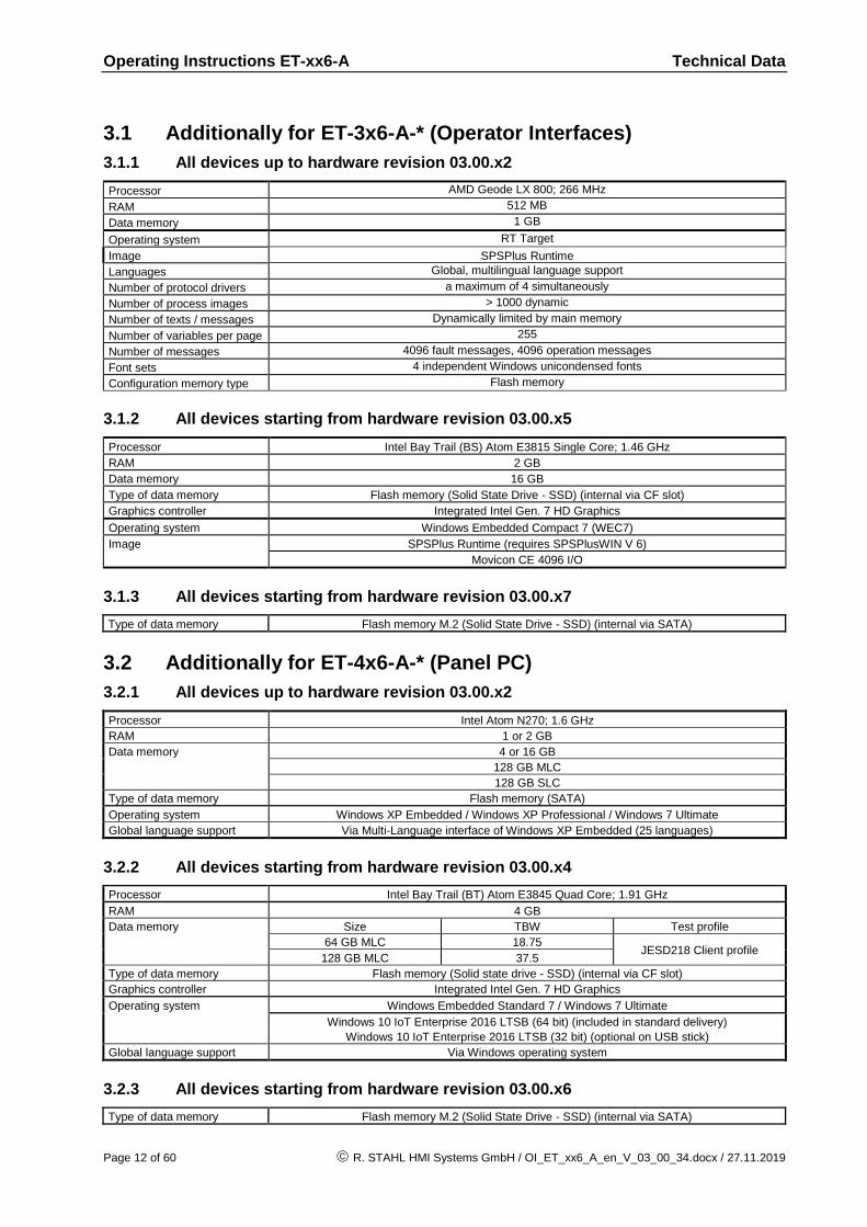
3.1 Additionally for ET-3x6-A-* (Operator Interfaces)
3.1.1 All devices up to hardware revision 03.00.x2
Processor AMD Geode LX 800; 266 MHz
RAM 512 MB
Data memory 1 GB
Operating system RT Target
Image SPSPlus Runtime
Languages Global, multilingual language support
Number of protocol drivers a maximum of 4 simultaneously
Number of process images > 1000 dynamic
Number of texts / messages Dynamically limited by main memory
Number of variables per page 255
Number of messages 4096 fault messages, 4096 operation messages
Font sets 4 independent Windows unicondensed fonts
Configuration memory type Flash memory
3.1.2 All devices starting from hardware revision 03.00.x5
Processor Intel Bay Trail (BS) Atom E3815 Single Core; 1.46 GHz
RAM 2 GB
Data memory 16 GB
Type of data memory Flash memory (Solid State Drive - SSD) (internal via CF slot)
Graphics controller Integrated Intel Gen. 7 HD Graphics
Operating system Windows Embedded Compact 7 (WEC7)
Image SPSPlus Runtime (requires SPSPlusWIN V 6)
Movicon CE 4096 I/O
3.1.3 All devices starting from hardware revision 03.00.x7
Type of data memory Flash memory M.2 (Solid State Drive - SSD) (internal via SATA)
3.2 Additionally for ET-4x6-A-* (Panel PC)
3.2.1 All devices up to hardware revision 03.00.x2
Processor Intel Atom N270; 1.6 GHz
RAM 1 or 2 GB
Data memory 4 or 16 GB
128 GB MLC
128 GB SLC
Type of data memory Flash memory (SATA)
Operating system Windows XP Embedded / Windows XP Professional / Windows 7 Ultimate
Global language support Via Multi-Language interface of Windows XP Embedded (25 languages)
3.2.2 All devices starting from hardware revision 03.00.x4
Processor Intel Bay Trail (BT) Atom E3845 Quad Core; 1.91 GHz
RAM 4 GB
Data memory Size TBW Test profile
64 GB MLC 18.75 JESD218 Client profile
128 GB MLC 37.5
Type of data memory Flash memory (Solid state drive - SSD) (internal via CF slot)
Graphics controller Integrated Intel Gen. 7 HD Graphics
Operating system Windows Embedded Standard 7 / Windows 7 Ultimate
Windows 10 IoT Enterprise 2016 LTSB (64 bit) (included in standard delivery)
Windows 10 IoT Enterprise 2016 LTSB (32 bit) (optional on USB stick)
Global language support Via Windows operating system
3.2.3 All devices starting from hardware revision 03.00.x6
Type of data memory Flash memory M.2 (Solid State Drive - SSD) (internal via SATA)

Operating Instructions ET-xx6-A Conformity to standards
R. STAHL HMI Systems GmbH / OI_ET_xx6_A_en_V_03_00_34.docx / 27.11.2019 Page 13 of 60
3.3 Additionally for ET-5x6-A-* (Thin Clients)
3.3.1 All devices up to hardware revision 03.00.x2
Processor AMD Geode LX 800; 266 MHz
RAM 512 MB
2 GB *
Data memory 1 GB
16 GB *
Operating system Windows Embedded Standard 2009 and Remote Firmware
Windows Embedded Standard 7, Remote Firmware and Delta V *
* The combination of 2 GB RAM with 16 GB data memory is only available for the operating system with Delta V !
3.3.2 All devices starting from hardware revision 03.00.x4
Processor Intel Bay Trail (BT) Atom E3845 Quad Core; 1.91 GHz
RAM 4 GB
Data memory 64 GB
Type of data memory Flash memory (Solid state drive - SSD) (internal via CF slot)
Graphics controller Integrated Intel Gen. 7 HD Graphics
Operating system Windows 10 IoT Enterprise and Remote Firmware
3.3.3 All devices starting from hardware revision 03.00.x6
Data memory Size TBW Test profile
64 GB MLC 18.75 JESD218 Client profile
128 GB MLC 37.5
Type of data memory Flash memory M.2 (Solid State Drive - SSD) (internal via SATA)
4 Conformity to standards
The ET-xx6-A-* HMI devices comply with the following standards and directives:
Standard
Classification 1st supplement
ATEX directive 2014/34/EU
IEC 60079-0 : 2011 General requirements
IEC 60079-1 : 2007 Flameproof enclosure "d"
IEC 60079-7 : 2006 Increased safety "e"
IEC 60079-11 : 2011 Intrinsic safety "i"
IEC 60079-18 : 2009 Encapsulation "m"
IEC 60079-28 : 2006 Optical radiation "op is"
IEC 60079-31 : 2008 Protected by enclosures "t" (dust)
The product corresponds to requirements from:
EN 60079-0 : 2012 + A11 : 2013 General requirements
EN 60079-1 : 2014 Flameproof enclosure "d"
EN 60079-7 : 2007 Increased safety "e"
EN 60079-7 : 2015 (from 01.08.2018)
EN 60079-11 : 2012 Intrinsic safety "i"
EN 60079-18 : 2015 Encapsulation "m"
EN 60079-28 : 2015 Optical radiation "op is"
EN 60079-31 : 2014 Protected by enclosures "t" (dust)
NOTICE
Operating Instructions ET-xx6-A Certificates
Page 14 of 60 R. STAHL HMI Systems GmbH / OI_ET_xx6_A_en_V_03_00_34.docx / 27.11.2019
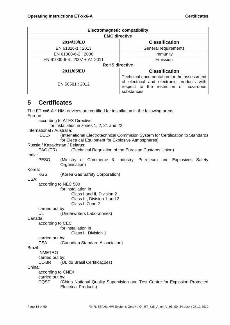
Electromagnetic compatibility
EMC directive
2014/30/EU Classification
EN 61326-1 : 2013 General requirements
EN 61000-6-2 : 2006 Immunity
EN 61000-6-4 : 2007 + A1 2011 Emission RoHS directive
2011/65/EU Classification
EN 50581 : 2012
Technical documentation for the assessment of electrical and electronic products with respect to the restriction of hazardous substances
5 Certificates
The ET-xx6-A-* HMI devices are certified for installation in the following areas: Europe: according to ATEX Directive for installation in zones 1, 2, 21 and 22 International / Australia: IECEx (International Electrotechnical Commision System for Certification to Standards
for Electrical Equipment for Explosive Atmospheres) Russia / Kazakhstan / Belarus: EAC (TR) (Technical Regulation of the Eurasian Customs Union) India: PESO (Ministry of Commerce & Industry, Petroleum and Explosives Safety
Organisation) Korea: KGS (Korea Gas Safety Corporation) USA: according to NEC 500 for installation in Class I and II, Division 2 Class III, Division 1 and 2 Class I, Zone 2 carried out by: UL (Underwriters Laboratories) Canada: according to CEC for installation in Class II, Division 1 carried out by: CSA (Canadian Standard Association) Brazil: INMETRO carried out by: UL-BR (UL do Brasil Certificações) China: according to CNEX carried out by: CQST (China National Quality Supervision and Test Centre for Explosion Protected
Electrical Products)
Operating Instructions ET-xx6-A Certificates
R. STAHL HMI Systems GmbH / OI_ET_xx6_A_en_V_03_00_34.docx / 27.11.2019 Page 15 of 60
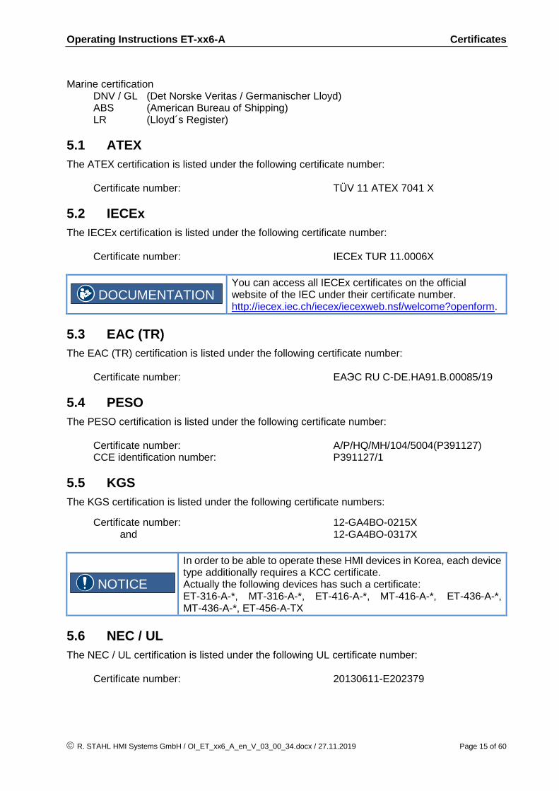
Marine certification DNV / GL (Det Norske Veritas / Germanischer Lloyd) ABS (American Bureau of Shipping) LR (Lloyd´s Register)
5.1 ATEX
The ATEX certification is listed under the following certificate number: Certificate number: TÜV 11 ATEX 7041 X
5.2 IECEx
The IECEx certification is listed under the following certificate number: Certificate number: IECEx TUR 11.0006X
You can access all IECEx certificates on the official website of the IEC under their certificate number. http://iecex.iec.ch/iecex/iecexweb.nsf/welcome?openform.
5.3 EAC (TR)
The EAC (TR) certification is listed under the following certificate number: Certificate number: EAЭC RU C-DE.HA91.B.00085/19
5.4 PESO
The PESO certification is listed under the following certificate number: Certificate number: A/P/HQ/MH/104/5004(P391127) CCE identification number: P391127/1
5.5 KGS
The KGS certification is listed under the following certificate numbers:
Certificate number: 12-GA4BO-0215X and 12-GA4BO-0317X
In order to be able to operate these HMI devices in Korea, each device type additionally requires a KCC certificate. Actually the following devices has such a certificate: ET-316-A-*, MT-316-A-*, ET-416-A-*, MT-416-A-*, ET-436-A-*, MT-436-A-*, ET-456-A-TX
5.6 NEC / UL
The NEC / UL certification is listed under the following UL certificate number: Certificate number: 20130611-E202379
DOCUMENTATION
NOTICE

Operating Instructions ET-xx6-A Certificates
Page 16 of 60 R. STAHL HMI Systems GmbH / OI_ET_xx6_A_en_V_03_00_34.docx / 27.11.2019
5.7 CEC / CSA
The CEC / CSA certification is listed under the following certificate number:
Certificate number: 2512677
5.8 INMETRO
The INMETRO certification is listed under the following UL-BR certificate number:
Certificate number: UL-BR 12.0265X
5.9 CNEX
The CNEX certification is listed under the following certificate number:
Certificate number: CNEx18.5523X
5.10 DNV / GL
The DNV / GL certification is listed under the following certificate number:
Certificate number: TAA00000WA
5.11 ABS
The ABS (American Bureau of Shipping) certification is listed under the following certificate number:
Certificate number: 15-HG1418766-1-PDA
5.12 LR
The LR certification is listed under the following certificate number:
Certificate number: 11/20035 (E1)
Operating Instructions ET-xx6-A Marking
R. STAHL HMI Systems GmbH / OI_ET_xx6_A_en_V_03_00_34.docx / 27.11.2019 Page 17 of 60
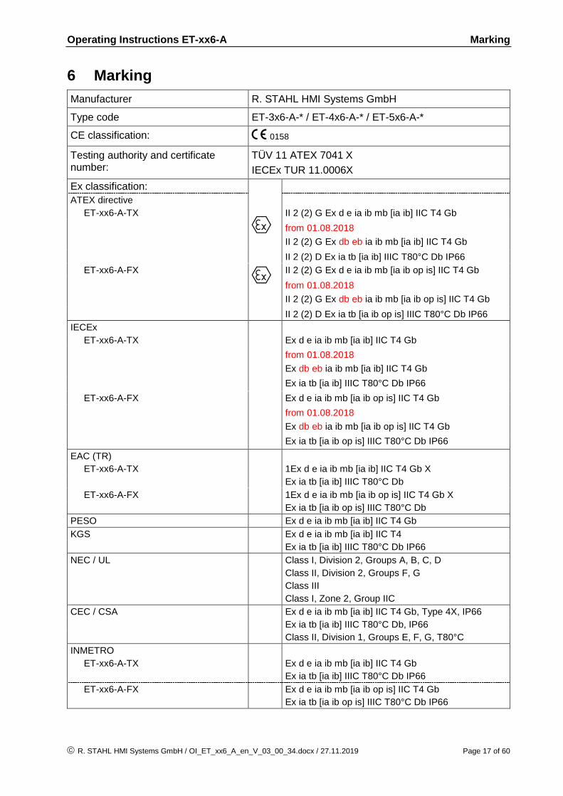
6 Marking
Manufacturer R. STAHL HMI Systems GmbH
Type code ET-3x6-A-* / ET-4x6-A-* / ET-5x6-A-*
CE classification: c 0158
Testing authority and certificate number:
TÜV 11 ATEX 7041 X
IECEx TUR 11.0006X Ex classification:
e
ATEX directive
ET-xx6-A-TX II 2 (2) G Ex d e ia ib mb [ia ib] IIC T4 Gb
from 01.08.2018
II 2 (2) G Ex db eb ia ib mb [ia ib] IIC T4 Gb
II 2 (2) D Ex ia tb [ia ib] IIIC T80°C Db IP66
ET-xx6-A-FX e II 2 (2) G Ex d e ia ib mb [ia ib op is] IIC T4 Gb
from 01.08.2018
II 2 (2) G Ex db eb ia ib mb [ia ib op is] IIC T4 Gb
II 2 (2) D Ex ia tb [ia ib op is] IIIC T80°C Db IP66
IECEx
ET-xx6-A-TX Ex d e ia ib mb [ia ib] IIC T4 Gb
from 01.08.2018
Ex db eb ia ib mb [ia ib] IIC T4 Gb
Ex ia tb [ia ib] IIIC T80°C Db IP66
ET-xx6-A-FX Ex d e ia ib mb [ia ib op is] IIC T4 Gb
from 01.08.2018
Ex db eb ia ib mb [ia ib op is] IIC T4 Gb
Ex ia tb [ia ib op is] IIIC T80°C Db IP66
EAC (TR)
ET-xx6-A-TX 1Ex d e ia ib mb [ia ib] IIC T4 Gb X
Ex ia tb [ia ib] IIIC T80°C Db
ET-xx6-A-FX 1Ex d e ia ib mb [ia ib op is] IIC T4 Gb X
Ex ia tb [ia ib op is] IIIC T80°C Db
PESO Ex d e ia ib mb [ia ib] IIC T4 Gb
KGS Ex d e ia ib mb [ia ib] IIC T4
Ex ia tb [ia ib] IIIC T80°C Db IP66
NEC / UL Class I, Division 2, Groups A, B, C, D
Class II, Division 2, Groups F, G
Class III
Class I, Zone 2, Group IIC
CEC / CSA Ex d e ia ib mb [ia ib] IIC T4 Gb, Type 4X, IP66
Ex ia tb [ia ib] IIIC T80°C Db, IP66
Class II, Division 1, Groups E, F, G, T80°C
INMETRO
ET-xx6-A-TX Ex d e ia ib mb [ia ib] IIC T4 Gb
Ex ia tb [ia ib] IIIC T80°C Db IP66
ET-xx6-A-FX Ex d e ia ib mb [ia ib op is] IIC T4 Gb
Ex ia tb [ia ib op is] IIIC T80°C Db IP66
Operating Instructions ET-xx6-A Power supply
Page 18 of 60 R. STAHL HMI Systems GmbH / OI_ET_xx6_A_en_V_03_00_34.docx / 27.11.2019
CNEX
ET-xx6-A-TX Ex d e ia ib mb [ia ib] IIC T4 Gb
Ex ia tb [ia ib] IIIC T80°C Db IP66
ET-xx6-A-FX Ex d e ia ib mb [ia ib op is] IIC T4 Gb
Ex ia tb [ia ib op is] IIIC T80°C Db IP66
7 Power supply
7.1 HMI devices
Power supply: 24.0 VDC (min. 20.4 VDC , max. 28.8 VDC / (-15 % / +20 %)) Up from 100 GB data memory (min. 21.6 VDC , max. 28.8 VDC / (-10 % / +20 %)) Power consumption: 1.2 A 7.1.1 HMI device terminals
Copper wires with cross sections of betwee 0.2 mm² (AWG24) and 2.5 mm² (AWG14) may be connected to any of the terminals of the HMI devices.
When connecting cables to the terminals please make sure that the insulation of the cables goes right up to the terminal contacts.
7.1.1.1 Tightening torque
For the terminals X1 and X11 a tightening torque of: 0.4 Nm up to 0.5 Nm is valid and for the terminals X2, X3, X4, X5, X6, X7, X8 and X9 a tightening torque of: 0.5 Nm bis 0.6 Nm is valid.
The stipulated tightening torques of the connection terminals must be observed and applied. Again, they must be checked and possibly adjusted before commissioning !
NOTICE
NOTICE

Operating Instructions ET-xx6-A Permitted maximum values
R. STAHL HMI Systems GmbH / OI_ET_xx6_A_en_V_03_00_34.docx / 27.11.2019 Page 19 of 60
8 Permitted maximum values
8.1 External, non-intrinsically safe circuits
Input voltage (X1):
Rated voltage 24 VDC (+20 % / -15 %) Power consumption at Urated 1.5 A max max. working voltage Um 30 VDC RS-422/-232 COM 1 (X2):
Rated voltage RS-422: 5 VDC RS-232: ±12 VDC Max. operating voltage Um 253 VAC USB-1 (X5):
Rated voltage 5 VDC Max. operating voltage Um 253 VAC USB-3 (X7):
Rated voltage 5 VDC Max. operating voltage Um 253 VAC Copper Ethernet (X11):
Rated voltage 5 VDC Rated power 100 mW Max. operating voltage Um 30 VDC Audio (X3):
Rated voltage 5 VDC Max. operating voltage Um 253 VAC
8.2 External inherently safe optical interface
Ethernet optical fiber (X10):
Wavelength 1350 nm Radiant power ≤ 35 mW
Operating Instructions ET-xx6-A Permitted maximum values
Page 20 of 60 R. STAHL HMI Systems GmbH / OI_ET_xx6_A_en_V_03_00_34.docx / 27.11.2019
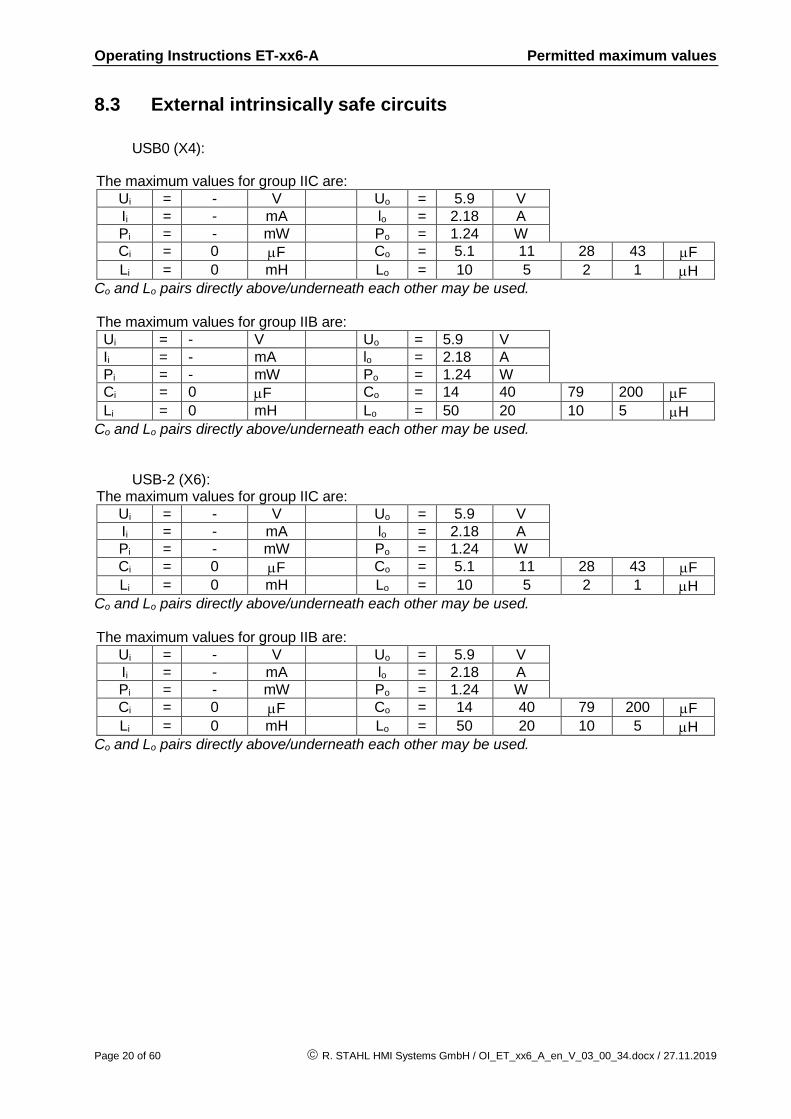
8.3 External intrinsically safe circuits
USB0 (X4):
The maximum values for group IIC are:
Ui = - V Uo = 5.9 V
Ii = - mA lo = 2.18 A
Pi = - mW Po = 1.24 W
Ci = 0 F Co = 5.1 11 28 43 F
Li = 0 mH Lo = 10 5 2 1 H
Co and Lo pairs directly above/underneath each other may be used. The maximum values for group IIB are:
Ui = - V Uo = 5.9 V
Ii = - mA lo = 2.18 A
Pi = - mW Po = 1.24 W
Ci = 0 F Co = 14 40 79 200 F
Li = 0 mH Lo = 50 20 10 5 H
Co and Lo pairs directly above/underneath each other may be used.
USB-2 (X6): The maximum values for group IIC are:
Ui = - V Uo = 5.9 V
Ii = - mA lo = 2.18 A
Pi = - mW Po = 1.24 W
Ci = 0 F Co = 5.1 11 28 43 F
Li = 0 mH Lo = 10 5 2 1 H
Co and Lo pairs directly above/underneath each other may be used. The maximum values for group IIB are:
Ui = - V Uo = 5.9 V
Ii = - mA lo = 2.18 A
Pi = - mW Po = 1.24 W
Ci = 0 F Co = 14 40 79 200 F
Li = 0 mH Lo = 50 20 10 5 H
Co and Lo pairs directly above/underneath each other may be used.
Operating Instructions ET-xx6-A Permitted maximum values
R. STAHL HMI Systems GmbH / OI_ET_xx6_A_en_V_03_00_34.docx / 27.11.2019 Page 21 of 60
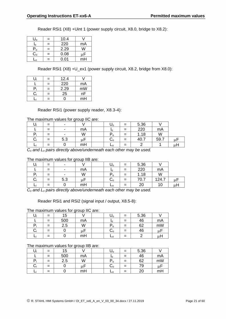
Reader RSi1 (X8) +Uint 1 (power supply circuit, X8.0, bridge to X8.2):
Uo = 10.4 V
lo = 220 mA
Po = 2.29 W
Co = 0.08 F
Lo = 0.01 mH
Reader RSi1 (X8) +U_ex1 (power supply circuit, X8.2, bridge from X8.0):
Ui = 12.4 V
Ii = 220 mA
Pi = 2.29 mW
Ci = 25 nF
Li = 0 mH
Reader RSi1 (power supply reader, X8.3-4):
The maximum values for group IIC are:
Ui = - V Uo = 5.36 V
Ii = - mA lo = 220 mA
Pi = - W Po = 1.18 W
Ci = 5.3 F Co = 40.7 59.7 F
Li = 0 mH Lo = 2 1 H
Co and Lo pairs directly above/underneath each other may be used. The maximum values for group IIB are:
Ui = - V Uo = 5.36 V
Ii = - mA lo = 220 mA
Pi = - W Po = 1.18 W
Ci = 5.3 F Co = 70.7 124.7 F
Li = 0 mH Lo = 20 10 H
Co and Lo pairs directly above/underneath each other may be used.
Reader RSi1 and RSi2 (signal input / output, X8.5-8):
The maximum values for group IIC are:
Ui = 15 V Uo = 5.36 V
Ii = 500 mA lo = 46 mA
Pi = 2.5 W Po = 62 mW
Ci = 0 F Co = 46 F
Li = 0 mH Lo = 2 H
The maximum values for group IIB are:
Ui = 15 V Uo = 5.36 V
Ii = 500 mA lo = 46 mA
Pi = 2.5 W Po = 62 mW
Ci = 0 F Co = 79 F
Li = 0 mH Lo = 20 mH

Operating Instructions ET-xx6-A Permitted maximum values
Page 22 of 60 R. STAHL HMI Systems GmbH / OI_ET_xx6_A_en_V_03_00_34.docx / 27.11.2019
Reader WCR1 (X8) (connection voltage supply, X8.1-2):
Ui = 11.4 V
Ii = 200 mA
Pi = 2.28 W
Ci = 25 nF
Li = 0 mH
Reader WCR1 (power supply reader, X8.3-4):
The maximum values for group IIC are:
Ui = - V Uo = 5.88 V
Ii = - mA lo = 200 mA
Pi = - mW Po = 1.18 W
Ci = 5.3 F Co = 27.7 37.7 F
Li = 0 mH Lo = 2 1 H
Co and Lo pairs directly above/underneath each other may be used. The maximum values for group IIB are:
Ui = - V Uo = 5.88 V
Ii = - mA lo = 200 mA
Pi = - mW Po = 1.18 W
Ci = 5.3 F Co = 55.7 94.7 F
Li = 0 mH Lo = 20 10 H
Co and Lo pairs directly above/underneath each other may be used.
Reader WCR1 and WCR2 (signal input / output, X8.5-8):
The maximum values for group IIC are:
Ui = 15 V Uo = 5.88 V
Ii = 500 mA lo = 51 mA
Pi = 2.5 W Po = 75 mW
Ci = 0 F Co = 34 F
Li = 0 mH Lo = 2 H
The maximum values for group IIB are:
Ui = 15 V Uo = 5.88 V
Ii = 500 mA lo = 51 mA
Pi = 2.5 W Po = 75 mW
Ci = 0 F Co = 63 F
Li = 0 mH Lo = 20 H
Operating Instructions ET-xx6-A Type code
R. STAHL HMI Systems GmbH / OI_ET_xx6_A_en_V_03_00_34.docx / 27.11.2019 Page 23 of 60
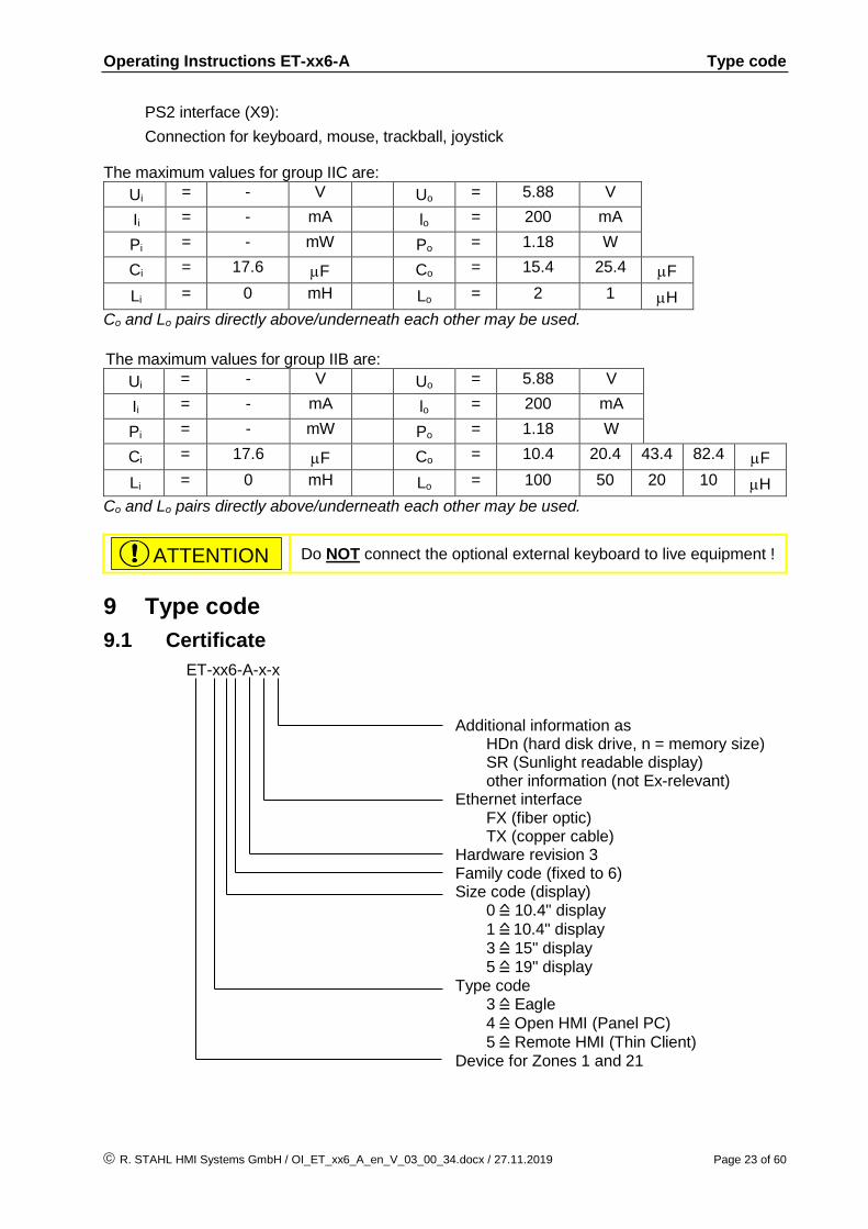
PS2 interface (X9):
Connection for keyboard, mouse, trackball, joystick
The maximum values for group IIC are:
Ui = - V Uo = 5.88 V
Ii = - mA lo = 200 mA
Pi = - mW Po = 1.18 W
Ci = 17.6 F Co = 15.4 25.4 F
Li = 0 mH Lo = 2 1 H
Co and Lo pairs directly above/underneath each other may be used.
The maximum values for group IIB are:
Ui = - V Uo = 5.88 V
Ii = - mA lo = 200 mA
Pi = - mW Po = 1.18 W
Ci = 17.6 F Co = 10.4 20.4 43.4 82.4 F
Li = 0 mH Lo = 100 50 20 10 H
Co and Lo pairs directly above/underneath each other may be used.
Do NOT connect the optional external keyboard to live equipment !
9 Type code
9.1 Certificate
ET-xx6-A-x-x Additional information as HDn (hard disk drive, n = memory size) SR (Sunlight readable display) other information (not Ex-relevant) Ethernet interface FX (fiber optic) TX (copper cable) Hardware revision 3 Family code (fixed to 6) Size code (display) 0 = 10.4" display
1 = 10.4" display
3 = 15" display 5 = 19" display Type code 3 = Eagle
4 = Open HMI (Panel PC)
5 = Remote HMI (Thin Client) Device for Zones 1 and 21
ATTENTION

Operating Instructions ET-xx6-A Type code
Page 24 of 60 R. STAHL HMI Systems GmbH / OI_ET_xx6_A_en_V_03_00_34.docx / 27.11.2019
9.2 Variants
9.2.1 ET-3x6-A (Operator Interfaces)
These versions apply to all Operator Interfaces up to hardware revision 03.00.x2, with AMD Geode LX processor.
ET-xxx-A-aa-bb-cc Reader modul Display version Ethernet interface 306 / 316 / 336
Device variant:
Classification product key Description
Type with
ET-3x6-A-FX-bb-cc Optical fiber Ethernet interface 100Base-FX (Ex op is)
ET-3x6-A-TX-bb-cc Copper Ethernet interface 10/100Base-TX (Ex e)
ET-3x6-A-aa-TFT-cc TFT Display (Standard)
ET-3x6-A-aa-SR-cc Sunlight readable Display 1000 cd/m² (only ET-336-A)
ET-3x6-A-aa-bb-RSi1 Plug-in module for reader with RS-232 interface, power supply via HMI device
9.2.2 ET-3x6-A-*-BS (Operator Interfaces)
These versions apply to all Operator Interfaces starting from hardware revision 03.00.x5, with Bay Trail Atom E3815 processor.
ET-xxx-A-aa-BS-bb-Rx-dd-ee-ff
Front plate Reader modul Data memory RAM Display version Processor type (fixed to BS = Bay Trail) Ethernet interface 306 / 316 / 336
Device variant:
Classification product key Description
Type with
ET-3x6-A-FX-BS-bb-Rx-dd-ee-ff Optical fiber Ethernet interface 100Base-FX (Ex op is)
ET-3x6-A-TX-BS-bb-Rx-dd-ee-ff Copper Ethernet interface 10/100Base-TX (Ex e)
ET-3x6-A-aa-BS-TFT-Rx-dd-ee-ff TFT Display (Standard)
ET-3x6-A-aa-BS-SR-Rx-dd-ee-ff Sunlight readable Display 1000 cd/m² (only ET-336-A-*-BS) (no longer available)
ET-3x6-A-aa-BS-bb-R2-dd-ee-ff 2 GB RAM
ET-3x6-A-aa-BS-bb-Rx-16GB-ee-ff 16 GB Solid State Drive
ET-3x6-A-aa-BS-bb-Rx-dd-RSi1-ff Plug-in module for reader with RS-232 interface, power supply via HMI device
ET-3x6-A-aa-BS-bb-Rx-dd-ee-PES Polyester front plate
NOTICE
NOTICE

Operating Instructions ET-xx6-A Type code
R. STAHL HMI Systems GmbH / OI_ET_xx6_A_en_V_03_00_34.docx / 27.11.2019 Page 25 of 60
9.2.3 ET-4x6-A (Panel PC)
These versions apply to all Panel PC's up to hardware revision 03.00.x2, with Atom N270 processor.
ET-xxx-A-aa-Rx-bb-cc-dd-ee Front plate Reader modul Data memory Display version Working memory Ethernet interface 406 / 416 / 436 / 456 Device variant:
Classification product key Description
Type with
ET-4x6-A-FX-Rx-bb-cc-dd-ee Optical fiber Ethernet interface100Base-FX (Ex op is)
ET-4x6-A-TX-Rx-bb-cc-dd-ee Copper Ethernet interface 10/100Base-TX (Ex e)
ET-4x6-A-aa-R1-bb-cc-dd-ee RAM memory 1 GB
ET-4x6-A-aa-R2-bb-cc-dd-ee RAM memory 2 GB
ET-4x6-A-aa-Rx-TFT-bb-cc-dd-ee TFT display (standard)
ET-4x6-A-aa-Rx-SR-bb-cc-dd-ee Sunlight readable display 1000 cd/m² (ET-436-A only)
ET-4x6-A-aa-Rx-bb-4GB-dd-ee 4 GB Solid State Drive (SSD)
ET-4x6-A-aa-Rx-bb-16GB-dd-ee 16 GB Solid State Drive (SSD)
ET-4x6-A-aa-Rx-bb-128GBM-dd-ee 128 GB Solid State Drive MLC
ET-4x6-A-aa-Rx-bb-128GBS-dd-ee 128 GB Solid State Drive SLC
ET-4x6-A-aa-Rx-bb-cc-RSi1-ee Plug-in module for reader with RS-232 interface, power supply via HMI device
ET-4x6-A-aa-Rx-bb-cc-dd-PES Polyester front plate
ET-4x6-A-aa-Rx-bb-cc-dd-VA Stainless steel front plate (436 and 456 only), NOT SR type
NOTICE

Operating Instructions ET-xx6-A Type code
Page 26 of 60 R. STAHL HMI Systems GmbH / OI_ET_xx6_A_en_V_03_00_34.docx / 27.11.2019
9.2.4 ET-4x6-A-*-BT (Panel PC)
These versions apply to all Panel PC's starting from hardware revision 03.00.x4, with Bay Trail Atom E3845 processor.
ET-xxx-A-aa-BT-Rx-bb-cc-dd-ee
Front plate Reader modul Data memory Display version RAM Processor type (fixed BT = Bay Trail) Ethernet interface 406 / 416 / 436 / 456 Device variant:
Classification product key Description
Type with
ET-4x6-A-FX-BT-Rx-bb-cc-dd-ee Optical fiber Ethernet interface100Base-FX (Ex op is)
ET-4x6-A-TX-BT-Rx-bb-cc-dd-ee Copper Ethernet interface 10/100Base-TX (Ex e)
ET-4x6-A-aa-BT-R3-bb-cc-dd-ee RAM 4 GB
ET-4x6-A-aa-BT-Rx-TFT-bb-cc-dd-ee TFT display (standard)
ET-4x6-A-aa-BT-Rx-SR-bb-cc-dd-ee Sunlight readable display 1000 cd/m² (ET-436-A-*-BT only) (no longer available)
ET-4x6-A-aa-BT-Rx-bb-64GB-dd-ee 64 GB Solid State Drive MLC
ET-4x6-A-aa-BT-Rx-bb-128GBM-dd-ee 128 GB Solid State Drive MLC
ET-4x6-A-aa-BT-Rx-bb-cc-RSi1-ee Plug-in module for reader with RS-232 interface, power supply via HMI device
ET-4x6-A-aa-BT-Rx-bb-cc-dd-PES Polyester front plate
ET-4x6-A-aa-BT-Rx-bb-cc-dd-VA Stainless steel front plate (436 and 456 only), NOT SR type
NOTICE

Operating Instructions ET-xx6-A Type code
R. STAHL HMI Systems GmbH / OI_ET_xx6_A_en_V_03_00_34.docx / 27.11.2019 Page 27 of 60
9.2.5 ET-5x6-A (Thin Client)
These versions apply to all Thin Client's up to hardware revision 03.00.x2, with AMD Geode LX processor.
ET-xxx-A-aa-bb-cc-dd Front plate Reader modul Display version Ethernet interface 536 / 556 Device variant:
Classification product key Description
Type with
ET-5x6-A-FX-bb-cc-dd Optical fiber Ethernet interface 100Base-FX (Ex op is)
ET-5x6-A-TX-bb-cc-dd Copper Ethernet interface 10/100Base-TX (Ex e)
ET-5x6-A-aa-TFT-cc-dd TFT display (standard)
ET-5x6-A-aa-SR-cc-dd Sunlight readable display 1000 cd/m² (ET-536-A only)
ET-5x6-A-aa-bb-RSi1-dd Plug-in module for reader with RS-232 interface, power supply via HMI device
ET-5x6-A-aa-bb-cc-PES Polyester front plate
ET-5x6-A-aa-bb-cc-VA Stainless steel front plate, NOT SR type
9.2.6 ET-5x6-A-*-BT (Thin Client)
These versions apply to all Thin Client's starting from hardware revision 03.00.x4, with Bay Trail Atom E3845 processor.
ET-xxx-A-aa-BT-Rx-bb-cc-dd-ee
Front plate Reader modul Data memory Display version RAM Processor type (fixed BT = Bay Trail) Ethernet interface 516 / 536 / 556 Device variant:
Classification product key Description
Type with
ET-5x6-A-FX-BT-Rx-bb-cc-dd-ee Optical fiber Ethernet interface 100Base-FX (Ex op is)
ET-5x6-A-TX-BT-Rx-bb-cc-dd-ee Copper Ethernet interface 10/100Base-TX (Ex e)
ET-5x6-A-aa-BT-R3-bb-cc-dd-ee RAM 4 GB
ET-5x6-A-aa-BT-Rx-TFT-bb-cc-dd-ee TFT display (standard)
ET-5x6-A-aa-BT-Rx-SR-bb-cc-dd-ee Sunlight readable display 1000 cd/m² (ET-536-A-*-BT only) (no longer available)
ET-5x6-A-aa-BT-Rx-bb-64GB-dd-ee 64 GB Solid State Drive (SSD)
ET-5x6-A-aa-BT-Rx-bb-128GB-dd-ee 128 GB Solid State Drive (SSD)
ET-5x6-A-aa-BT-Rx-bb-cc-RSi1-ee Plug-in module for reader with RS-232 interface, power supply via HMI device
ET-5x6-A-aa-BT-Rx-bb-cc-dd-PES Polyester front plate
ET-5x6-A-aa-BT-Rx-bb-cc-dd-VA Stainless steel front plate, NOT SR type
NOTICE
NOTICE

Operating Instructions ET-xx6-A Safety Advice
Page 28 of 60 R. STAHL HMI Systems GmbH / OI_ET_xx6_A_en_V_03_00_34.docx / 27.11.2019
10 Safety Advice
This chapter is a summary of the key safety measures. The summary is supplementary to existing rules which staff also have to study.
The safety of persons and equipment in hazardous areas depends on compliance with all relevant safety regulations. Thus, the installation and maintenance staff carry a particular responsibility, requiring precise knowledge of the applicable regulations and conditions.
The notes listed below in section 10.1 must be heeded to avoid injury and damage to equipment !
10.1 Installation and operation
Please note the following when installing and operating the device:
The in each case valid national regulations for installation and assembly apply (e.g. IEC/EN 60079-14).
The HMI device has been certified as a fixed installed device. It must be fixed with a bracket or be secured in another way at a specified position.
The HMI device must be disconnected from the mains for a change of position. The EPL must be adhered to.
The HMI device must only be switched on when it is closed.
The HMI devices may be installed in zones 1, 2, 21 or 22.
For use according to NEC / UL, please refer to drawings 201717540 and 201133510. Any pre-installations made ex-factory may have to be complemented accordingly.
The intrinsically safe circuits must be installed according to applicable regulations.
When installed in zones 1, 2, 21 and 22, intrinsically safe devices suitable for categories 2G, 3G, 2D and 3D may be connected to the intrinsically safe power supply circuits.
If the HMI devices are installed in areas exposed to the risk of dust explosions, the maximum values of Group IIB apply to the intrinsically safe circuits.
Interconnecting several active devices in an intrinsically safe circuit may result in different safe maximum values. This could compromise intrinsic safety !
The safe maximum values of the connected field device(s) must correspond to the values listed on the data sheet or the EC type examination certificate.
During assembly and operation of the HMI device electrostatic surface charging must not exceed that caused by manual rubbing.
After switching the HMI device off, wait for at least 1 minute before opening it.
Before opening the housing lid users must ensure that all non-intrinsically safe circuits have been switched off. Circuits supplied from different sources may be connected ! Please note that all associated equipment (such as the SK-KJ1710, for example) must also be switched off !
The HMI device and any connected equipment must be incorporated into the same potential equalization system (see installation example in the Hardware Manual). An alternative would be to connect only devices that are safely isolated from earth potential.
NOTICE
CAUTION
Operating Instructions ET-xx6-A Safety Advice
R. STAHL HMI Systems GmbH / OI_ET_xx6_A_en_V_03_00_34.docx / 27.11.2019 Page 29 of 60
National safety and accident prevention rules.
Generally accepted technical rules.
Safety instructions contained in these operating instructions.
Any damage may compromise the explosion protection !
Use the device for its intended purpose only (see "Device Function"). Incorrect or unauthorized use and non-compliance with the instructions in this manual will void any warranty on our part. No changes to the device that compromise its explosion protection are permitted ! The device may only be installed and operated in an undamaged, dry and clean condition !
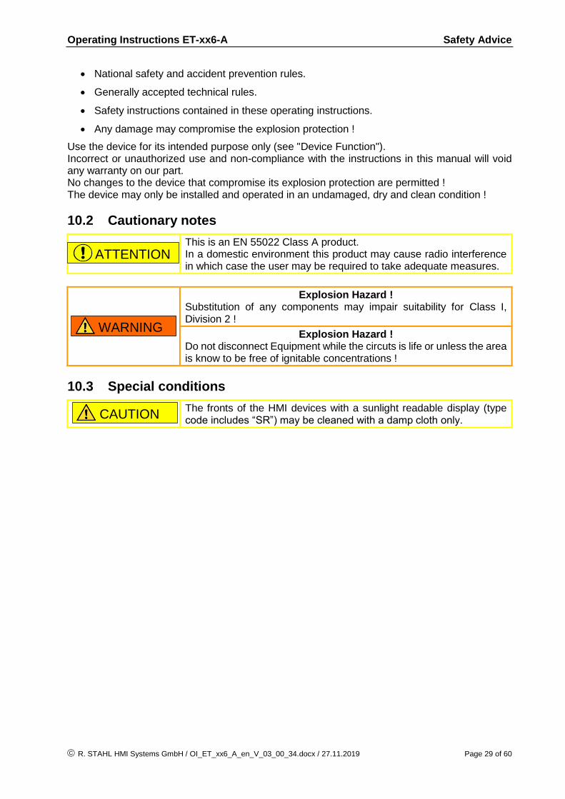
10.2 Cautionary notes
This is an EN 55022 Class A product. In a domestic environment this product may cause radio interference in which case the user may be required to take adequate measures.
Explosion Hazard ! Substitution of any components may impair suitability for Class I, Division 2 !
Explosion Hazard ! Do not disconnect Equipment while the circuts is life or unless the area is know to be free of ignitable concentrations !
10.3 Special conditions
The fronts of the HMI devices with a sunlight readable display (type code includes “SR”) may be cleaned with a damp cloth only.
WARNING
CAUTION
ATTENTION

Operating Instructions ET-xx6-A Installation
Page 30 of 60 R. STAHL HMI Systems GmbH / OI_ET_xx6_A_en_V_03_00_34.docx / 27.11.2019
11 Installation
11.1 General information
Electrical plants are subject to certain regulations concerning installation and operation (e.g. RL 1999/92/EC, RL 2014/34/EU and IEC/EN 60079-14).
It is the responsibility of the operators of electrical installations in hazardous environments to ensure that the equipment is kept in proper condition, is operated according to instructions and that maintenance and repairs are carried out.
11.2 ET-xx6-A-*
Operators must ensure compliance with the examination certificates before installation. Users must adhere to any “special conditions” therein. Also of importance are the maximum electrical operating values specified therein.
The earth / ground (PE) connector at the back of the HMI device housing must be connected to the equipotential bonding conductor of the hazardous area. The earthing cable's cross section must be at least 4 mm² (AWG12) and it must be fitted with a suitable cable lug. To prevent equalizing currents flowing to the earth / ground (PE) system of the HMI device it is necessary to safely isolate any connected devices from earth or to integrate them into the earth / ground (PE) system of the HMI device.
The PE connection part of the HMI device located at the back of the housing is internally connected with the GND supply cable (X1 pins 3 and 4).
The HMI devices can be mounted and operated in any position. Sufficient air circulation must be ensured, however, so that the maximum operating temperature is not exceeded.
Intrinsically safe and non intrinsically safe conducting connection parts must be installed with a minimum distance of 50 mm [0.16 ft].
When connecting the HMI devices to the intrinsically safe circuits of the associated equipment the respective maximum values of the field unit and the associated equipment must be observed to ensure explosion protection (proof of intrinsic safety).
The HMI device's front should be protected by a canopy against permanent exposure to UV light. This increases the front membrane's lifespan. The canopy MUST NOT be too close to the front plate and sufficient air circulation must be ensured.
The ET-4x6-A-* and ET-5x6-A-* devices may be operated at +55 °C [+131 °F] ONLY FOR SHORT PERIODS at a time.
11.2.1 HMI device Installation in housings type of protection "e" or "t"
If the HMI devices ET-xx6-A-* are mounted inside a cut out of a suitable housing of protection type Ex e or Ex t, its mechanical protection regarding impact and IP code protection up to IP65 is maintained even after the device has been installed. The internal separation requirements and the temperature assessment of the Ex e housing must be in accordance with the applicable standards. The clearance of HMI device terminals to other bare conducting parts (excepting ground) inside the Ex e housing shall be at least 50 mm [0.16 ft].
NOTICE

Operating Instructions ET-xx6-A Installation
R. STAHL HMI Systems GmbH / OI_ET_xx6_A_en_V_03_00_34.docx / 27.11.2019 Page 31 of 60
11.2.2 Cable glands
The enclosures of HMI devices are fitted with type STAHL 8161/* and type HSK-MZ-Ex cable glands. These are certified for installation in zone 1 and 21 and correspond to the temperature range of the device.
Unused cable glands must be closed with certified screw plugs or stopping plugs.
Open enclosure holes without cable glands are not permitted and must be closed with a certified screw plug. This certified screw plug must have an equal or higher area of certification (zone) and permitted temperature range, and the same country approval (e.g. ATEX for Europe) as the HMI device.
Alternative, similar and certified cable glands may be used provided they have an equal or higher area of certification (zone) and permitted temperature range, and the same country approval (e.g. ATEX for Europe) as the HMI device.
The tightening torques for the cable glands may vary depending on the cables and wires used. The users have to determine and apply the required torques themselves. In the case of ex-factory systems, all components are installed correctly and in accordance with applicable standards. Since storage or temperature etc. can have an impact on the cables and cable glands, the pre-installed screw connections must be checked and possibly tightened before commissioning. If they are too loose or too tight, the type of protection, sealing or strain relief might be negatively impacted. Cable glands with cap nut and without strain relief clamp should only be used for permanently installed cables and electrical lines. Installation of the required strain relief is the responsibility of the system set-up engineer.
Operating Instructions ET-xx6-A Installation
Page 32 of 60 R. STAHL HMI Systems GmbH / OI_ET_xx6_A_en_V_03_00_34.docx / 27.11.2019
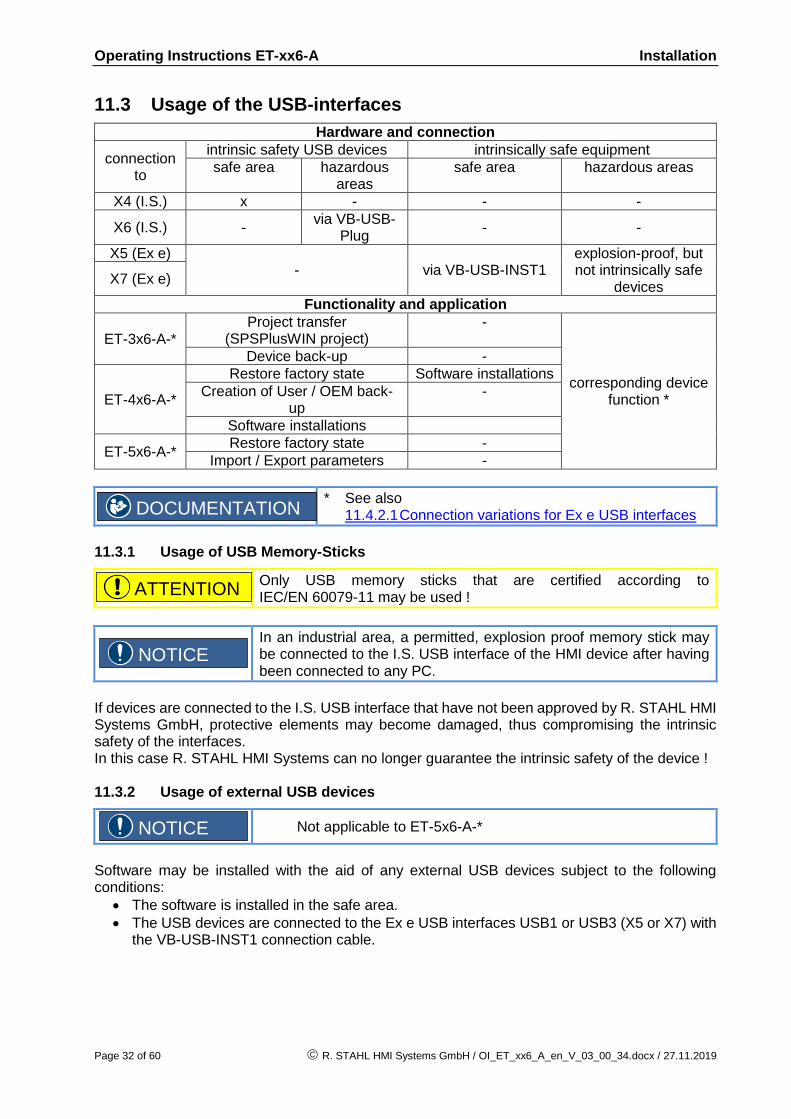
11.3 Usage of the USB-interfaces
Hardware and connection
connection to
intrinsic safety USB devices intrinsically safe equipment
safe area hazardous areas
safe area hazardous areas
X4 (I.S.) x - - -
X6 (I.S.) - via VB-USB-
Plug - -
X5 (Ex e) - via VB-USB-INST1
explosion-proof, but not intrinsically safe
devices X7 (Ex e)
Functionality and application
ET-3x6-A-* Project transfer
(SPSPlusWIN project) -
corresponding device function *
Device back-up -
ET-4x6-A-*
Restore factory state Software installations
Creation of User / OEM back-up
-
Software installations
ET-5x6-A-* Restore factory state -
Import / Export parameters -
* See also 11.4.2.1 Connection variations for Ex e USB interfaces
11.3.1 Usage of USB Memory-Sticks
Only USB memory sticks that are certified according to IEC/EN 60079-11 may be used !
In an industrial area, a permitted, explosion proof memory stick may be connected to the I.S. USB interface of the HMI device after having been connected to any PC.
If devices are connected to the I.S. USB interface that have not been approved by R. STAHL HMI Systems GmbH, protective elements may become damaged, thus compromising the intrinsic safety of the interfaces. In this case R. STAHL HMI Systems can no longer guarantee the intrinsic safety of the device ! 11.3.2 Usage of external USB devices
Not applicable to ET-5x6-A-*
Software may be installed with the aid of any external USB devices subject to the following conditions:
The software is installed in the safe area.
The USB devices are connected to the Ex e USB interfaces USB1 or USB3 (X5 or X7) with the VB-USB-INST1 connection cable.
DOCUMENTATION
ATTENTION
NOTICE
NOTICE
Operating Instructions ET-xx6-A Installation
R. STAHL HMI Systems GmbH / OI_ET_xx6_A_en_V_03_00_34.docx / 27.11.2019 Page 33 of 60
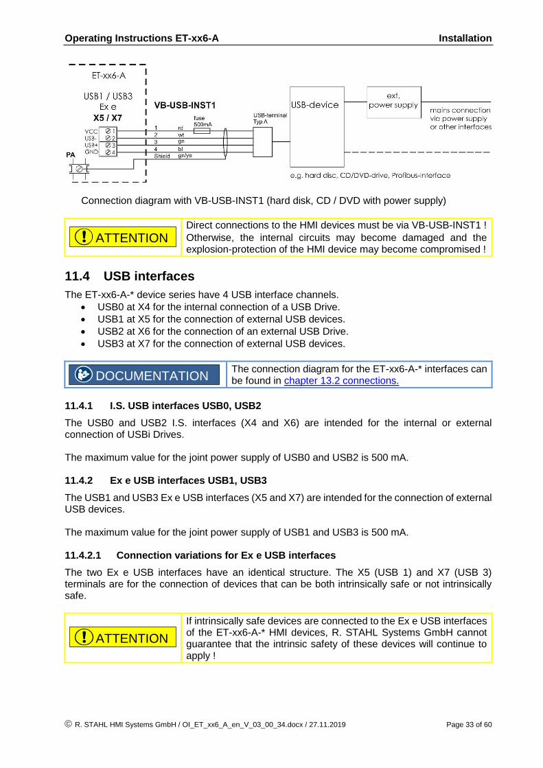
Connection diagram with VB-USB-INST1 (hard disk, CD / DVD with power supply)
Direct connections to the HMI devices must be via VB-USB-INST1 !
Otherwise, the internal circuits may become damaged and the explosion-protection of the HMI device may become compromised !
11.4 USB interfaces
The ET-xx6-A-* device series have 4 USB interface channels.
USB0 at X4 for the internal connection of a USB Drive.
USB1 at X5 for the connection of external USB devices.
USB2 at X6 for the connection of an external USB Drive.
USB3 at X7 for the connection of external USB devices.
The connection diagram for the ET-xx6-A-* interfaces can be found in chapter 13.2 connections.
11.4.1 I.S. USB interfaces USB0, USB2
The USB0 and USB2 I.S. interfaces (X4 and X6) are intended for the internal or external connection of USBi Drives. The maximum value for the joint power supply of USB0 and USB2 is 500 mA. 11.4.2 Ex e USB interfaces USB1, USB3
The USB1 and USB3 Ex e USB interfaces (X5 and X7) are intended for the connection of external USB devices. The maximum value for the joint power supply of USB1 and USB3 is 500 mA. 11.4.2.1 Connection variations for Ex e USB interfaces
The two Ex e USB interfaces have an identical structure. The X5 (USB 1) and X7 (USB 3) terminals are for the connection of devices that can be both intrinsically safe or not intrinsically safe.
If intrinsically safe devices are connected to the Ex e USB interfaces of the ET-xx6-A-* HMI devices, R. STAHL Systems GmbH cannot guarantee that the intrinsic safety of these devices will continue to apply !
ATTENTION
DOCUMENTATION
ATTENTION
Operating Instructions ET-xx6-A Installation
Page 34 of 60 R. STAHL HMI Systems GmbH / OI_ET_xx6_A_en_V_03_00_34.docx / 27.11.2019
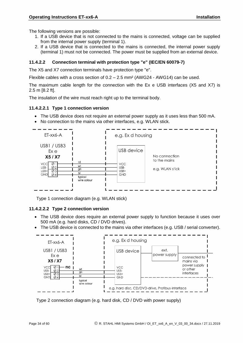
The following versions are possible: 1. If a USB device that is not connected to the mains is connected, voltage can be supplied
from the internal power supply (terminal 1). 2. If a USB device that is connected to the mains is connected, the internal power supply
(terminal 1) must not be connected. The power must be supplied from an external device. 11.4.2.2 Connection terminal with protection type "e" (IEC/EN 60079-7)
The X5 and X7 connection terminals have protection type "e".
Flexible cables with a cross section of 0.2 – 2.5 mm² (AWG24 - AWG14) can be used.
The maximum cable length for the connection with the Ex e USB interfaces (X5 and X7) is 2.5 m [8.2 ft].
The insulation of the wire must reach right up to the terminal body. 11.4.2.2.1 Type 1 connection version
The USB device does not require an external power supply as it uses less than 500 mA.
No connection to the mains via other interfaces, e.g. WLAN stick.
Type 1 connection diagram (e.g. WLAN stick) 11.4.2.2.2 Type 2 connection version
The USB device does require an external power supply to function because it uses over 500 mA (e.g. hard disks, CD / DVD drives).
The USB device is connected to the mains via other interfaces (e.g. USB / serial converter).
Type 2 connection diagram (e.g. hard disk, CD / DVD with power supply)

Operating Instructions ET-xx6-A Assembly and disassembly
R. STAHL HMI Systems GmbH / OI_ET_xx6_A_en_V_03_00_34.docx / 27.11.2019 Page 35 of 60
11.4.2.2.3 Type 3 connection version
The USB device does require an external power supply to function because it uses over 500 mA (e.g. hard disks, CD / DVD drives).
The USB device is connected to the mains via other interfaces (e.g. USB / serial converter).
The USB device needs the VCC connection of the HMI device (internal supply – terminal 1) to function.
Type 3 connection diagram (any USB device with power supply)
12 Assembly and disassembly
12.1 General information
Assembly and disassembly are subject to general technical rules. Additional, specific safety regulations apply to electronic and pneumatic installations.
12.2 Cut-out ET-xx6-A-*
Make a cut-out with the following dimensions:
HMI device Width Height Depth of cut-
out Material thickness
ET-x06-A-* 385.5 ± 0.5 mm [1.26 ± 0.0016 ft]
257.5 ± 0.5 mm [0.84 ± 0.0016 ft]
150 mm [0.49 ft] up to 8 mm [0.0087 ft]
ET-x16-A-* 359.5 ± 0.5 mm [1.18 ± 0.0016 ft]
257.5 ± 0.5 mm [0.84 ± 0.0016 ft]
150 mm [0.49 ft] up to 8 mm [0.0087 ft]
ET-x36-A-* 427.5 ± 0.5 mm [1.40 ± 0.0016 ft]
327.5 ± 0.5 mm [1.07 ± 0.0016 ft]
165 mm [0.54 ft] up to 8 mm [0.0087 ft]
ET-x56-A-* 522.5 ± 0.5 mm [1.71 ± 0.0016 ft]
412.5 ± 0.5 mm [1.35 ± 0.0016 ft]
165 mm [0.54 ft] up to 8 mm [0.0087 ft]
NOTICE
Operating Instructions ET-xx6-A Operation
Page 36 of 60 R. STAHL HMI Systems GmbH / OI_ET_xx6_A_en_V_03_00_34.docx / 27.11.2019
13 Operation
13.1 General information
When operating the devices, particular care shall be taken that:
the HMI device has been properly installed according to instructions,
the device is undamaged,
the terminal compartment is clean,
all screws are tightened fast,
before switching the HMI device on, its external PE terminal is properly connected to the equipotential bonding system at its place of use,
the cover of the terminal compartment is completely closed.
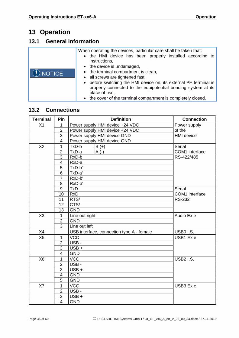
13.2 Connections
Terminal Pin Definition Connection
X1 1 Power supply HMI device +24 VDC Power supply
2 Power supply HMI device +24 VDC of the
3 Power supply HMI device GND HMI device
4 Power supply HMI device GND
X2 1 TxD-b B (+) Serial
2 TxD-a A (-) COM1 interface
3 RxD-b RS-422/485
4 RxD-a
5 TxD-b'
6 TxD-a'
7 RxD-b'
8 RxD-a'
9 TxD Serial
10 RxD COM1 interface
11 RTS/ RS-232
12 CTS/
13 GND
X3 1 Line out right Audio Ex e
2 GND
3 Line out left
X4 USB interface, connection type A - female USB0 I.S.
X5 1 VCC USB1 Ex e
2 USB -
3 USB +
4 GND
X6 1 VCC USB2 I.S.
2 USB -
3 USB +
4 GND
5 GND
X7 1 VCC USB3 Ex e
2 USB -
3 USB +
4 GND
NOTICE

Operating Instructions ET-xx6-A Operation
R. STAHL HMI Systems GmbH / OI_ET_xx6_A_en_V_03_00_34.docx / 27.11.2019 Page 37 of 60
X8 0 +U_INT1 Reader interface
1 0V I.S.
2 +U_EX1
3 GND
4 +U_RD
5 Signal 1
6 Signal 2
7 Signal 3
8 Signal 4
9 +U_EX1 (out)
X9 1 VCC PS2 interface *
2 KBDAT I.S.
3 KBCLK for
4 MSDAT external keyboard /
5 MSCLK mouse
6 GND
X10 1 Optical fiber connection type duplex SC - female Ethernet optical fiber interface **
X11 1 TxD (+) Ethernet copper
2 TxD (-) Connection **
3 RxD (+)
4 RxD (-)
The COM interface may only be wired as a RS-232 or as a RS-422/485 connection !
Simultaneous wiring of the RS-232 and RS-422/485 interface is not allowed !
* Do NOT connect the optional external keyboard to live equipment ! ** Please note that the Ethernet connection is either for an optical
fibre connection (X10) or for a copper connection (X11), depending on the version ordered !
The optical fiber connection requires a multimode optical fiber cable with 62.5 µm core diameter and 125 µm external diameter.
Copper wires with cross sections of between 0.2 mm² (AWG24) and 2.5 mm² (AWG14) may be connected to any of the terminals of the HMI devices.
Which cable cross sections are chosen should be decided on the basis of relevant regulations, such as DIN VDE 0298. Factors that might require a larger cross section, such as current, increased temperatures, cable bundling, etc. must also be taken into account !
NOTICE

Operating Instructions ET-xx6-A Operation
Page 38 of 60 R. STAHL HMI Systems GmbH / OI_ET_xx6_A_en_V_03_00_34.docx / 27.11.2019
13.2.1 Dip switch settings S3 and S4
Switch Position Interface Function
S3-1 OFF
COM1 RS-422/485
No bus terminator resistor set
ON Bus terminator resistor TxD line
S3-2 OFF No bus terminator resistor set
ON Bus terminator resistor RxD line
S4-1 S4-2 S4-3 Interface Keying
0 0 0
RS-422
Automatic keying
0 1 0 Keying always on
0 0 1 Keying enabled by SW
0 1 1 Driver in idle mode
1 0 0
RS-485
Automatic keying
1 1 0 Status not permitted !!!
1 0 1 Keying enabled by SW
1 1 1 Driver in idle mode
S4-4 OFF
Touch Without function ON
13.2.2 Status LEDs
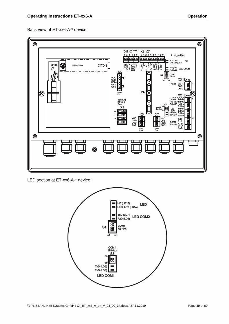
The status of the respective LEDs at the HMI devices indicates the activity of the corresponding data lines. These LEDs are located underneath the additional back lid that covers the interface circuit board. This additional back lid needs to be removed in order to see these LEDs.
In hazardous areas the HMI device must not be operated without the housing lid !
The status LEDs can therefore only be observed at the first start-up or in safe areas.
13.2.2.1 LEDs
Definition Colour Name Description
LD5 green COM1 TxD Activity on COM1: sending, LED flashing
LD8 yellow COM1 RxD Activity on COM1: receiving, LED flashing
LD7 green COM2 TxD Activity on COM2: sending, LED flashing
LD6 yellow COM2 RxD Activity on COM2: receiving, LED flashing
LD14 yellow LINK ACT Ethernet link established, LED always on Activity on Ethernet link, LED flashing
LD15 green HD Access to system disk (Solid State, HDD), LED flashing (only for ET-4x6-A-* devices)
CAUTION
Operating Instructions ET-xx6-A Operation
R. STAHL HMI Systems GmbH / OI_ET_xx6_A_en_V_03_00_34.docx / 27.11.2019 Page 39 of 60
Back view of ET-xx6-A-* device:
LED section at ET-xx6-A-* device:
Operating Instructions ET-xx6-A Operation
Page 40 of 60 R. STAHL HMI Systems GmbH / OI_ET_xx6_A_en_V_03_00_34.docx / 27.11.2019
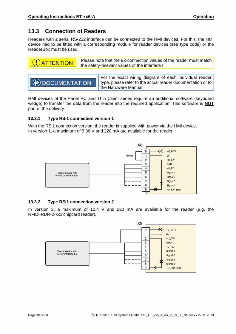
13.3 Connection of Readers
Readers with a serial RS-232 interface can be connected to the HMI devices. For this, the HMI device had to be fitted with a corresponding module for reader devices (see type code) or the ReaderBox must be used.
Please note that the Ex-connection values of the reader must match the safety-relevant values of the interface !
For the exact wiring diagram of each individual reader type, please refer to the actual reader documentation or to the Hardware Manual.
HMI devices of the Panel PC and Thin Client series require an additional software (keyboard wedge) to transfer the data from the reader into the required application. This software is NOT part of the delivery ! 13.3.1 Type RSi1 connection version 1
With the RSi1 connection version, the reader is supplied with power via the HMI device. In version 1, a maximum of 5.36 V and 220 mA are available for the reader.
13.3.2 Type RSi1 connection version 2
In version 2, a maximum of 10.4 V and 220 mA are available for the reader (e.g. the RFIDi-RDR-2-xxx chipcard reader).
ATTENTION
DOCUMENTATION

Operating Instructions ET-xx6-A Maintenance, service
R. STAHL HMI Systems GmbH / OI_ET_xx6_A_en_V_03_00_34.docx / 27.11.2019 Page 41 of 60
14 Maintenance, service
Associated equipment is subject to maintenance, service and testing according to guidelines 1999/92/EC, IEC/EN 60079-14, -17, -19 and BetrSichVer (Betriebssicherheitsverordnung - Occupational Safety and Health) !
Because the transmission of the devices remains reliable and stable over long periods of time, regular adjustments are not required. The following principles apply to repairs *, spare parts purchase* or exchange of parts * (where this can be done by the user !):
Only original parts provided by the manufacturer must be used.
Fuses may only be replaced by equivalent fuse types.
* Please also note section Troubleshooting !
The ET-xx6-A-* series HMI devices are maintenance-free across their entire lifespan. System maintenance should focus on the following:
a. Seal wear b. Display damage c. All screws are tightened fast d. All cables and lines are properly connected and undamaged
If the device in its factory state is damaged or altered in any way, decommission it immediately and contact the manufacturer !
14.1 Damaged sealing
If the surrounding seal of the device is damaged, the manufacturer will tick the “No hazloc approved panel mount“ option on the device.
The device is only approved for installation inside an Ex e or Ex tb enclosure if no "No hazloc approved panel mount" option is indicated on the device. If the "No hazloc approved panel mount" option is indicated on the device, certification according to NEC / CEC is no longer possible or becomes void !
14.2 Servicing
In accordance with IEC/EN 60079-19 and IEC/EN 60079-17, operators of electric plants in hazardous areas are obliged to have them serviced by qualified electricians.
14.3 Saving data with ET-3x6-A-*
All online data is stored on the internal flash card and are therefore also available after the device has been switched off for a long time. According to the current state-of-the-art the flash cards retain stored data for about 10 years.
NOTICE
DOCUMENTATION
NOTICE
CAUTION
Operating Instructions ET-xx6-A Troubleshooting
Page 42 of 60 R. STAHL HMI Systems GmbH / OI_ET_xx6_A_en_V_03_00_34.docx / 27.11.2019
14.4 Time function
Does not apply to ET-5x6-A-*: When the ET-3x6-A-* and ET-4x6-A-* HMI devices are switched off, their clock function is maintained by a battery and a capacitor. As long as the battery is intact, the clock function is maintained. Once the battery fails, the capacitor takes over and maintains the clock function for about four days. If the HMI device is switched on after a longer interval than that, the time and date have to be re-set manually or via a connected system.
15 Troubleshooting
Devices operated in hazardous areas must not be modified. Repairs may only be carried out by qualified, authorized staff specially trained for this purpose.
Repairs may only be carried out by specially trained staff who are familiar with all basic conditions of the applicable user regulations and – if requested – have been authorized by the manufacturer.
16 Disposal
Disposal of old electric and electronic devices, packaging and used parts is subject to regulations valid in whichever country the device has been installed. For countries under the jurisdiction of the EU the corresponding WEEE directive applies. The HMI devices are classified according to the table below:
old new
Directive WEEE I Directive 2002/96/EC WEEE II Directive 2012/19/EU
Valid until 14.08.2018 from 15.08.2018
Category 9
Monitoring and control devices
SG2 Screens, monitors, and equipment
containing screens >100 cm²
We shall take back our devices according to our General Terms and Conditions.
16.1 RoHS directive 2011/65/EC
The revised version of the RoHS (restriction of hazardous substances) 2002/95/EC directive, directive 2011/65/EC, extends its area of application to all electric and electronic products. The HMI devices are conform with the requirements from RoHS directive 2011/65/EU, dated 03.01.2013. 16.1.1 China RoHS labelling
According to new Chinese legislation in force since 01.03.2007, all devices containing hazardous substances must be labeled accordingly. The part of all toxic or hazardous substance contained in the homogeneous materials of the HMI devices is below the limit requirements in SJ/T11363-2006.
NOTICE

Operating Instructions ET-xx6-A General information
R. STAHL HMI Systems GmbH / OI_ET_xx6_A_en_V_03_00_34.docx / 27.11.2019 Page 43 of 60
17 General information
17.1 Touch driver
The UPDD touch driver is copyrighted licensed software supplied strictly for use with original R. STAHL HMI Systems GmbH touch systems and under no circumstances should this driver be downloaded or used on any other equipment !
17.2 Keyboard features
The information according the keyboard features applies ONLY to the 300 and 400 SERIES of HMI devices, and NOT to the 500 SERIES.
Pressing two keys at once (e.g. F1 + F7) is not supported by the HMI devices ! In such a case, the system considers the key that was pressed first as "active" and implements the associated functions and / or key bit functions ! The key pressed second is ignored.
The key kombination of Ctrl + Alt + Del can NOT be realized via the virtual keyboard !
For this you must use an external connected keyboard !
If you like to have a simulation from the key kombination of Ctrl + Alt + Del via the F-keys of the HMI device, it must be stated when ordering, as it can only be done by the manufacturer before delivery.
Pressing the keys F1, F2 and F8 at the same time, if the F-key simulation is activated, it has the same effect as pressing Ctrl + Alt + Del !
ET-306-A-* only: Pressing the S1 – S10 softkeys on the ET-306-A-* has the same effect as pressing the numerical keys (num lock) 0 – 9. At the image Movicon CE only the S1 – S10 softkeys are allocated as the combination of Shift + F1 – Shift + F10 keys function.
ET-406-A-* only: Pressing the S1 – S10 softkeys on the ET-406-A-* has the same effect as pressing the combination of Shift + F1 – Shift + F10 keys function.
NOTICE
NOTICE

Operating Instructions ET-xx6-A General information
Page 44 of 60 R. STAHL HMI Systems GmbH / OI_ET_xx6_A_en_V_03_00_34.docx / 27.11.2019
17.3 ET-4x6-A-* (Panel PC)
17.3.1 Up to Windows 7 operating systems
17.3.1.1 Licensing issues
The Panel PC devices SERIES 400 which are pre-installed with a Windows operating system are equipped with a license sticker. The license sticker is affixed on the back of the HMI device, next to the type plate. Please note that according to the license issued for Windows the application of this system as an Office PC is not permitted.
Please also note the information on the licensing stipulations for Windows operating systems contained in the "TechNote Windows Operating Systems" file located on the CD / DVD / USB stick, which is part of the delivery.
17.3.1.2 Note on Windows Embedded operating systems
When using the Windows Embedded operating systems (XP or Windows Standard 2009 / 7) on the Panel PC devices SERIES 400, the C:\ system drive can be protected from unauthorised writing (EWF).
This is NOT the case with other Windows operating systems !
R. STAHL HMI Systems GmbH recommends you leave the write protection filter on at all times !
For further information regarding this Write Protection (EWF), please refer to the OpenHMI_help_en.chm help file in the "STAHL" folder on the device or on the CD / DVD / USB stick that is included in the delivery.
17.3.2 Windows® 10 IoT Enterprise 2016 LTSB operating system
The operating system is based on Windows 10 for PC platforms with 64 bit x86 processors. For the LTSB (Long-Time-Service-Branch) versions, Microsoft guarantees 10 years of security updates and new builds with feature updates only every 2-3 years, with these being optional. The LTSB versions are ideal for industrial applications and feature additional security components such as write filters (UWF) and HORM (start of a system snapshot from the RAM plus write protection). From 2016 LTSB onwards, Microsoft has tied its licensing model to the processor performance: ENTRY for AMD® GX and ATOM™ VALUE for Intel® Core i5™ HIGH for Intel® Core i7™ The Panel PC SERIES 400 HMI devices with Windows 10 IoT Enterprise 2016 LTSB operating systems have the license provided as part of the image, with the corresponding label affixed to the back of the device. When delivered, the devices have already been registered and activated. The EOL (End of Life) date for Windows 10 IoT Enterprise 2016 LTSB for support and updates has been set by Microsoft to 31.07.2026.
DOCUMENTATION
DOCUMENTATION
NOTICE
ATTENTION

Operating Instructions ET-xx6-A General information
R. STAHL HMI Systems GmbH / OI_ET_xx6_A_en_V_03_00_34.docx / 27.11.2019 Page 45 of 60
17.3.2.1 Recovery
If a Panel PC is reset to the factory state (recovered) it will remain registered but will have to be reactivated ! This requires an active internet connection to a Microsoft server !
17.3.2.2 Company-specific Windows installations
The Windows 10 IoT license key is tied to STAHL images ! The installation of own Windows 10 IoT operating systems requires a separate license key !
All necessary drivers are provided by R.STAHL HMI Systems GmbH. Please contact our Support department.
17.3.3 Initial start-up
When the device is started for the first time, the Windows installation assistant starts where users have to select certain settings. Please follow the instructions of the installation assistant. 17.3.4 Recovery Stick
To restore your Panel PC device to its original state you will need a Recovery Stick, which is available as an optional extra. This recovery stick (USB-drive, also available intrinsically safe) contains the factory image, with which the system can be restored to delivery status within a very short time.
Please note that you can restore the HMI devices to their original state only with the aid of the Recovery Stick
As an option, the recovery stick can also contain a backup software, with which you can back up your own device configuration.
17.3.5 Back-up
Please note that it is the sole responsibility of the operator to generate a back-up of the HMI devices and their overall function.
We strongly recommend such a back-up to be stored on an external storage medium or on the company network.
NOTICE
NOTICE
NOTICE
NOTICE

Operating Instructions ET-xx6-A General information
Page 46 of 60 R. STAHL HMI Systems GmbH / OI_ET_xx6_A_en_V_03_00_34.docx / 27.11.2019
17.3.6 Switching off / closing down
The Microsoft Windows operating system stores key data in the main memory, regardless of the application, and has to store this data on the hard disk before the HMI device is switched off.
It is therefore important for the safe and correct operation that the HMI device is closed down properly (see illustration below) and NOT simply switched off. Otherwise the existing image of the device may be damaged, rendering the HMI device non-functioning.
After the data has been stored, Windows informs the user that the HMI device can now be switched off.
Only switch off the HMI device once you have received this message !
17.3.7 Data loss
In the case of applications that require constant writing into memory, R. STAHL HMI systems recommends you use external storage media (USB sticks, network servers) for these write processes.
Try and avoid cyclical writes (log files, databases, etc.) to the SSD ! The endurance of an SSD depends on the number of write cycles (TBW / terabytes written). Writing to the SSD with a simultaneous drop in voltage is most likely going to result in data loss !
NOTICE
ATTENTION
ATTENTION
NOTICE
ATTENTION
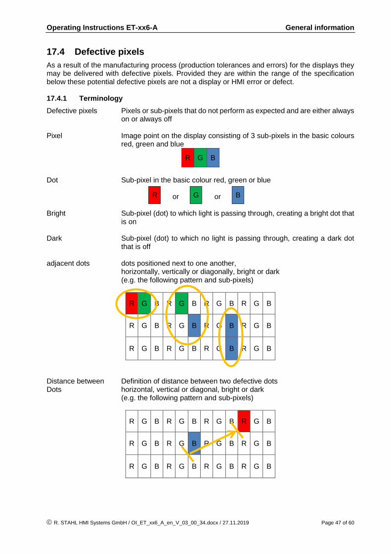
Operating Instructions ET-xx6-A General information
R. STAHL HMI Systems GmbH / OI_ET_xx6_A_en_V_03_00_34.docx / 27.11.2019 Page 47 of 60
17.4 Defective pixels
As a result of the manufacturing process (production tolerances and errors) for the displays they may be delivered with defective pixels. Provided they are within the range of the specification below these potential defective pixels are not a display or HMI error or defect. 17.4.1 Terminology
Defective pixels Pixels or sub-pixels that do not perform as expected and are either always on or always off
Pixel Image point on the display consisting of 3 sub-pixels in the basic colours
red, green and blue
R G B
Dot Sub-pixel in the basic colour red, green or blue or or Bright Sub-pixel (dot) to which light is passing through, creating a bright dot that
is on Dark Sub-pixel (dot) to which no light is passing through, creating a dark dot
that is off adjacent dots dots positioned next to one another, horizontally, vertically or diagonally, bright or dark (e.g. the following pattern and sub-pixels)
R G B R G B R G B R G B
R G B R G B R G B R G B
R G B R G B R G B R G B
Distance between Definition of distance between two defective dots Dots horizontal, vertical or diagonal, bright or dark (e.g. the following pattern and sub-pixels)
R G B R G B R G B R G B
R G B R G B R G B R G B
R G B R G B R G B R G B
R G B

Operating Instructions ET-xx6-A General information
Page 48 of 60 R. STAHL HMI Systems GmbH / OI_ET_xx6_A_en_V_03_00_34.docx / 27.11.2019
17.4.2 Display specification
Type of defect / description max. number of permitted defects
10.4" display 15" display 19" display
Linear defect (horizontal, vertical) not permitted
Defective pixels
bright dots ≤ 3 ≤ 2 ≤ 2
dark dots ≤ 4 ≤ 3 ≤ 5
total number of dots ≤ 5 ≤ 5 ≤ 5
adjacent dots
2 bright dots not permitted ≤ 1 pair ≤ 1 pair
more than 3 bright dots not permitted
2 dark dots ≤ 1 pair ≤ 1 pair ≤ 2 pairs
more than 3 dark dots not permitted
Distance between the dots
between 2 bright dots not permitted ≥ 15 mm ≥ 15 mm
between 2 dark dots ≤ 5 mm ≥ 15 mm ≥ 15 mm
between 1 bright and 1 dark dot
≤ 15 mm ≥ 15 mm ≥ 15 mm

Operating Instructions ET-xx6-A Certification Drawing NEC / UL
R. STAHL HMI Systems GmbH / OI_ET_xx6_A_en_V_03_00_34.docx / 27.11.2019 Page 49 of 60
18 Certification Drawing NEC / UL
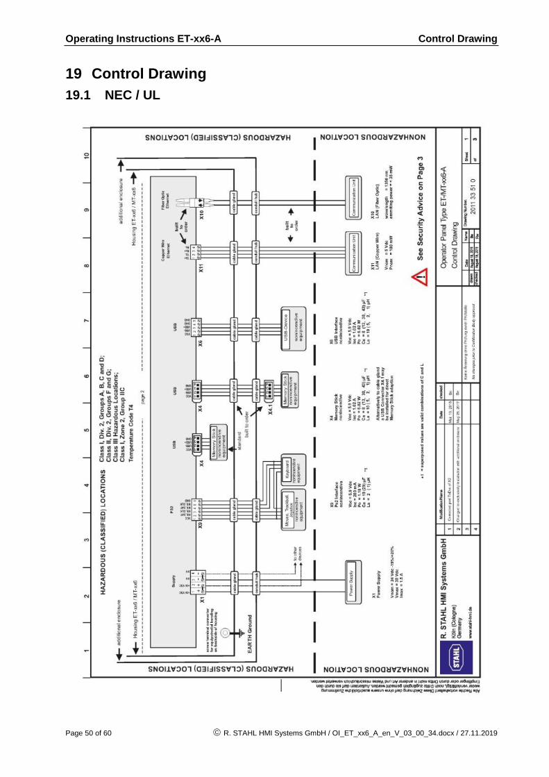
Operating Instructions ET-xx6-A Control Drawing
Page 50 of 60 R. STAHL HMI Systems GmbH / OI_ET_xx6_A_en_V_03_00_34.docx / 27.11.2019
19 Control Drawing
19.1 NEC / UL
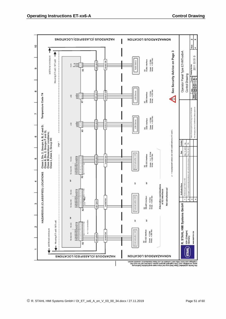
Operating Instructions ET-xx6-A Control Drawing
R. STAHL HMI Systems GmbH / OI_ET_xx6_A_en_V_03_00_34.docx / 27.11.2019 Page 51 of 60
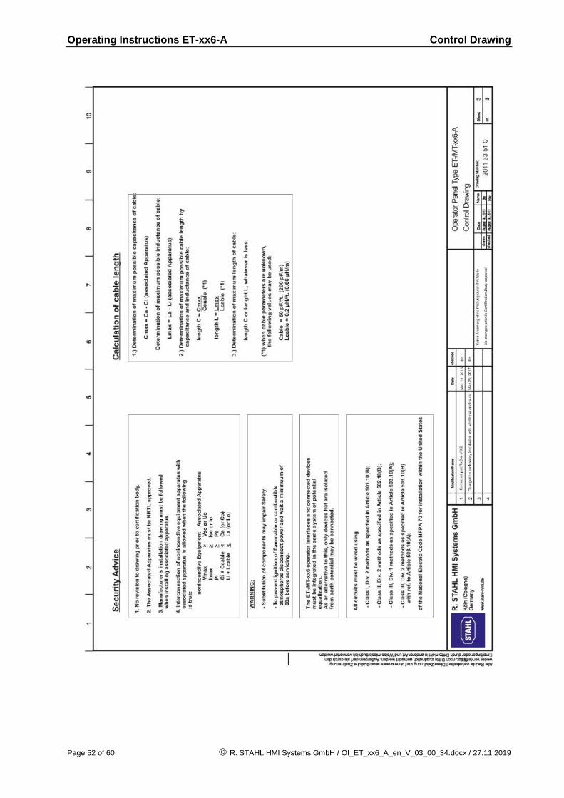
Operating Instructions ET-xx6-A Control Drawing
Page 52 of 60 R. STAHL HMI Systems GmbH / OI_ET_xx6_A_en_V_03_00_34.docx / 27.11.2019
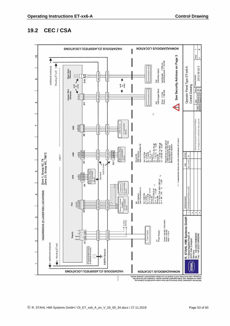
Operating Instructions ET-xx6-A Control Drawing
R. STAHL HMI Systems GmbH / OI_ET_xx6_A_en_V_03_00_34.docx / 27.11.2019 Page 53 of 60
19.2 CEC / CSA
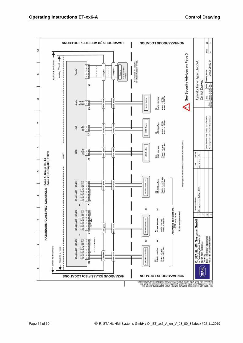
Operating Instructions ET-xx6-A Control Drawing
Page 54 of 60 R. STAHL HMI Systems GmbH / OI_ET_xx6_A_en_V_03_00_34.docx / 27.11.2019

Operating Instructions ET-xx6-A Control Drawing
R. STAHL HMI Systems GmbH / OI_ET_xx6_A_en_V_03_00_34.docx / 27.11.2019 Page 55 of 60

Operating Instructions ET-xx6-A Declaration of EC conformity
Page 56 of 60 R. STAHL HMI Systems GmbH / OI_ET_xx6_A_en_V_03_00_34.docx / 27.11.2019
20 Declaration of EC conformity
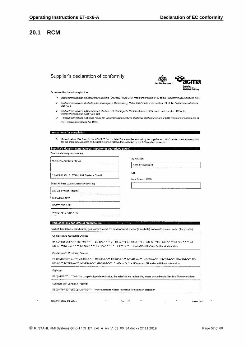
Operating Instructions ET-xx6-A Declaration of EC conformity
R. STAHL HMI Systems GmbH / OI_ET_xx6_A_en_V_03_00_34.docx / 27.11.2019 Page 57 of 60
20.1 RCM
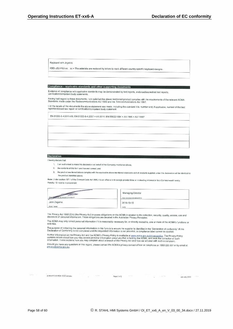
Operating Instructions ET-xx6-A Declaration of EC conformity
Page 58 of 60 R. STAHL HMI Systems GmbH / OI_ET_xx6_A_en_V_03_00_34.docx / 27.11.2019
Operating Instructions ET-xx6-A Release notes
R. STAHL HMI Systems GmbH / OI_ET_xx6_A_en_V_03_00_34.docx / 27.11.2019 Page 59 of 60
21 Release notes
The chapter entitled "Release Notes" contains all the changes made in every version of the Operating Instructions. Version 03.00.31
Removal of previous release notes
Changing Disclaimer
Addition of information according to "HMI Types" in "Technical Data"
Addition of "Technical Data" for data memory at 5x6, staring from HW ref 03.00x6
Addition of 126 GB version at Thin Client BT
Removal of chapter "Exicom-SHD-xxx hard disk"
Addition of "textbox caution" in section "Maintenance, overhaul" with information according to "decommission the device"
Addition of RCM declaration of conformity
Formal changes Version 03.00.32
Update of CNEX certificate number
Addition / changing of CNEX marking
Formal changes Version 03.00.33
Addition of table "Overview hardware revision"
Formal changes Version 03.00.34
Changing text "Notice" in section "Usage of USB Memory-Sticks", removal of "non-"
Dip switch S4-4 "changing function"
Addition of section "Touch driver"
Changing section "General informationen", Notice moved into section "keyboard features"
Changing "text at notice" "COM interface connection" in section "Connections"
Renew / changing EAC certificate number
Formal changes

R. STAHL HMI Systems GmbH Adolf-Grimme-Allee 8 D 50829 Köln T: (switchboard) +49 221 76 806 - 1000 (Hotline) +49 221 76 806 - 5000 F: +49 221 76 806 - 4100 E: (switchboard) [email protected] (hotline) [email protected] r-stahl.com stahl-hmi.de