Embed Size (px)
Citation preview

1
Operating Instructions Four-Ball Tester (FBT)
to DIN 51350 1. Safety rules
1.1. Observance of safety rules 1.2. Normal use 1.3. Safety features on the four-ball tester 1.4. Transport and setting up 1.5. At the workplace 1.6. Cleaning and servicing 1.7. Electrical equipment 1.8. In emergency 1.9. In the event of fire 1.10. Mobile phones 1.11. Accessories 1.12. Protecting the environment
2. Operation
2.1. Switching on: 2.2. Switching off: 2.3. Control and monitoring unit: 2.4. Adjusting the sliding weight (Item 30): 2.5. Fitting the extra weights (Items 36 & 37):
2
2.6. Ball holder: 2.6.1. Inserting and mounting the ball holder: 2.6.2. Removing the ball holder:
2.7. Ball cup (Item 10):
2.7.1. Loading the ball cup: 2.7.2. Unloading the ball cup:
2.8. Types of test:
3. Test specification
3.1. Types of test
3.1.1. To be attended to before every test: 3.1.2. Standard short-time tests 3.1.3. Long-time tests 3.1.4. Testing of materials:
3.2. Events taking place during tests:
3.2.1. Conditions at low loads: 3.2.2. Conditions at high loads:
3.2.2.1. Abrasion diameter: 3.2.2.2. The 2.5-second abrasion-delay time:
3.2.3. Conditions at very high loads:
3
4. Servicing 4.1. Spindle mounting: 4.2. Ball holder (Item 3): 4.3. Ball cup: 4.4. Centre and knife-edge bearings:
5. Transport / setting-up (mechanical and electrical installation)
5.1. Installation site: 5.2. Ground quality: 5.3. Floor-space required: 5.4. Mechanical installation:
5.4.1. Installing the housing (Item 1): 5.4.2. Installing the support for the recording devices (Item 19): 5.4.3. Weight beam (Item 24):
5.4.3.1. Installing the weight beam (Item 24): 5.4.3.2. Counterbalancing the weight beam:
5.4.4. Installing the pushrod (Item 22), ram (Item 20), bearing (Item 64) and turntable (Item 21): 5.4.5. Installing the sliding weight (Item 30): 5.4.6. Fitting the extra weights (Items 36 & 37): 5.4.7. Fitting the base for the control and monitoring unit (Group 7): 5.4.8. Fitting the control and monitoring unit (Group 7):
4
5.5. Electrical installation:
6. Replacement/wearing parts: assembly drawing 7. Electrical equipment / circuit diagram Appendices: A-1: Load sequence for 10, 20 / 50 kg A-2: Measuring microscope (accessory) A-3: Tractiv force dynamometer

5
1. Safety rules 1.1. Observance of safety rules: This four-ball tester embodies the latest technology; it is safe and reliable in operation when properly used in compliance with the safety rules. The relevant accident-prevention regulations and other generally recognised safety rules must be observed. Observe the safety rules: your health is at stake. All persons involved in setting up, operating, servicing, repairing and/or inspecting the four-ball tester must have read and understood the safety rules below. The four-ball tester may be operated only by authorised skilled personnel trained in its use. Responsibility for operating, servicing and maintaining the four-ball tester must be clearly defined and adhered to. 1.2. Normal use: The four-ball tester is suitable for testing lubricants mechanically. Abnormal or improper use may: − endanger life and limb, − endanger the environment, and also − endanger the four-ball tester, and − endanger other physical resources
6
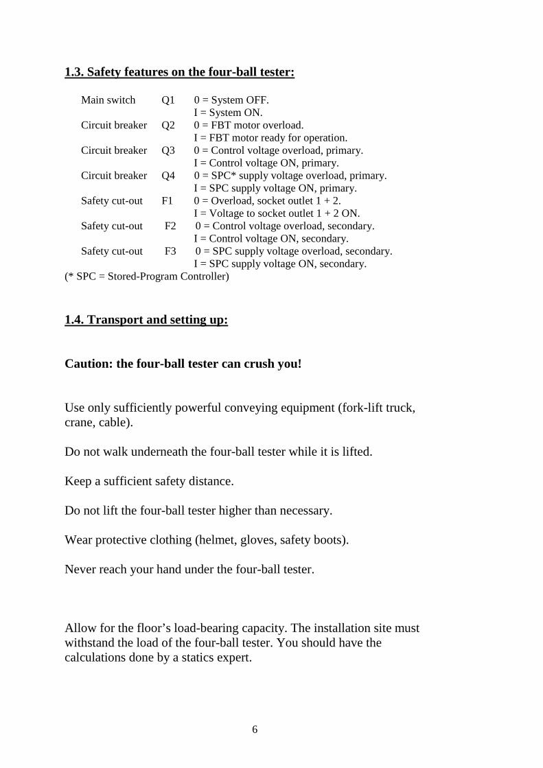
1.3. Safety features on the four-ball tester:
Main switch Q1 0 = System OFF. I = System ON.
Circuit breaker Q2 0 = FBT motor overload. I = FBT motor ready for operation. Circuit breaker Q3 0 = Control voltage overload, primary.
I = Control voltage ON, primary. Circuit breaker Q4 0 = SPC* supply voltage overload, primary.
I = SPC supply voltage ON, primary. Safety cut-out F1 0 = Overload, socket outlet 1 + 2. I = Voltage to socket outlet 1 + 2 ON. Safety cut-out F2 0 = Control voltage overload, secondary. I = Control voltage ON, secondary. Safety cut-out F3 0 = SPC supply voltage overload, secondary. I = SPC supply voltage ON, secondary. (* SPC = Stored-Program Controller) 1.4. Transport and setting up: Caution: the four-ball tester can crush you! Use only sufficiently powerful conveying equipment (fork-lift truck, crane, cable). Do not walk underneath the four-ball tester while it is lifted. Keep a sufficient safety distance. Do not lift the four-ball tester higher than necessary. Wear protective clothing (helmet, gloves, safety boots). Never reach your hand under the four-ball tester. Allow for the floor’s load-bearing capacity. The installation site must withstand the load of the four-ball tester. You should have the calculations done by a statics expert.
7
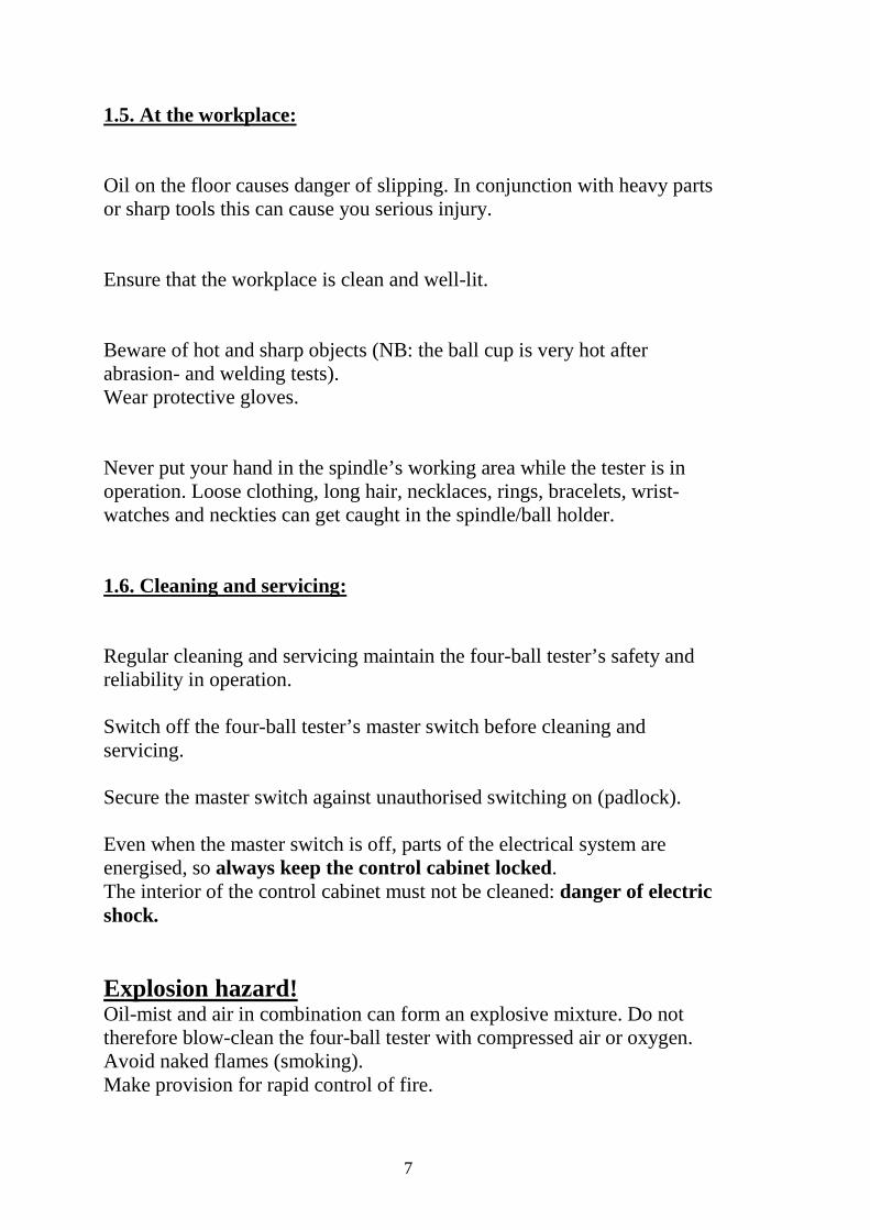
1.5. At the workplace: Oil on the floor causes danger of slipping. In conjunction with heavy parts or sharp tools this can cause you serious injury. Ensure that the workplace is clean and well-lit. Beware of hot and sharp objects (NB: the ball cup is very hot after abrasion- and welding tests). Wear protective gloves. Never put your hand in the spindle’s working area while the tester is in operation. Loose clothing, long hair, necklaces, rings, bracelets, wrist-watches and neckties can get caught in the spindle/ball holder. 1.6. Cleaning and servicing: Regular cleaning and servicing maintain the four-ball tester’s safety and reliability in operation. Switch off the four-ball tester’s master switch before cleaning and servicing. Secure the master switch against unauthorised switching on (padlock). Even when the master switch is off, parts of the electrical system are energised, so always keep the control cabinet locked. The interior of the control cabinet must not be cleaned: danger of electric shock. Explosion hazard! Oil-mist and air in combination can form an explosive mixture. Do not therefore blow-clean the four-ball tester with compressed air or oxygen. Avoid naked flames (smoking). Make provision for rapid control of fire.

8
Cleaning agents which attack plastics, rubber or paints must not be used. They may damage cables, sockets and indicators. Cleaning agents may contain substances harmful to health. Follow the manufacturer’s guidelines. 1.7. Electrical equipment: All work on the electrical equipment such as connection to the mains, servicing and repairs may be carried out only by qualified specialists. Even when the master switch is off, parts of the electrical system are energised. 1.8. In emergency: Master switch to OFF "0". Give First Aid, call ambulance or doctor if persons have been injured. 1.9. In the event of fire: Switch off power supply (cut-out). Call fire brigade. Use only CO2 (carbon dioxide) to extinguish. 1.10. Mobile phones: Caution: mobile phones should not be used near the four-ball tester. Interference affecting the control and monitoring unit cannot be ruled out.
9
1.11. Accessories: Fitting of accessories and other modifications to the four-ball tester require approval from Hansa Press- und Maschinenbau GmbH. No attachments or modifications may be made to the four-ball tester which might impair its safety or reliability in operation. 1.12. Protection of the environment: For the environment’s sake ensure that used test- and service materials are properly disposed of.
2. Operation 2.1. Switching on: Four-Ball Tester ready to operate: Main switch (Q1) ON “I”. Caution: Danger of injury. Never reach into the spindle operating space while the Four-Ball Tester is switched on (main switch position (Q1) ON “I”) Never put your hand into the rotating spindle working area while the Four-Ball Tester is operating. When working inside the spindle operating area: Make sure that the main switch is in the position OFF “0”. 2.2. Switching off: “System off” main switch (Q1) OFF “0”.
10
2.3 Control and monitoring unit
Descrption of the controls on the front of the switchgear cabinet(circuit diagram)
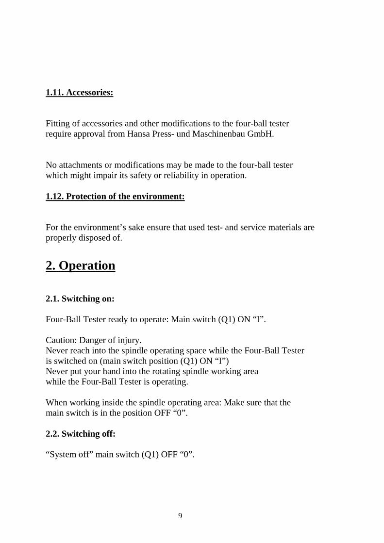
U4: Display and Operating Unit This device is equipped with all control and display elements needed to set up and start the four ball tester. The unit performs a self test after turning on the main switch (Q1). Once the self test is finished, the first screen of the operating unit opens.
Fig. 1: U4 display and operating unit The FBT (four ball tester) is operated via menus. The selections depicted by the display can be used directly on the screen. A new screen with menus opens once a key has been pressed or a digit has been entered. The figure above depicts the start screen. The following is an example used to illustrate how to operate the unit. Example: A test is to be performed for one hour without frequency converter (FC). First, enter the nominal value. Press the desired language to open the selection menu screen. Use nominal values setting to open the rotation, counter, and time setting menu screen. However, since the time has to be set, use the down arrow key on the key panel on the right 2x. The number for the seconds starts flashing (set time). Use the number keys to enter a number between 0 and 60 and confirm with ENTER. Use the down arrow key 1x and the minutes start flashing. Use the number keys to enter a number between 0 and 60 and confirm with ENTER. Use the down arrow key 1x and the hours start flashing. Use the number keys to enter a number between 0 and 999 (this example uses 1) and confirm with ENTER.
11
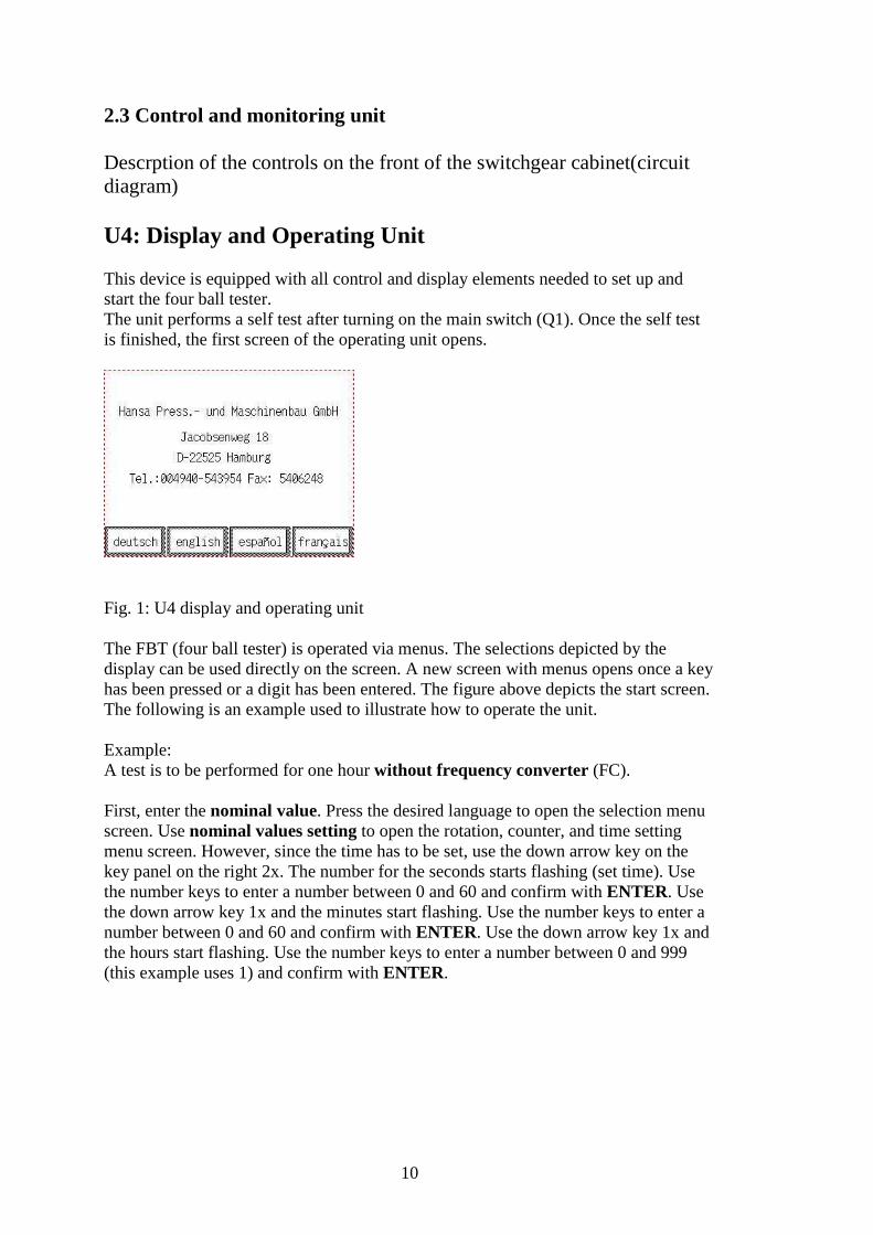
Start Screen
Press the desired language (e.g. “english”)
The selection menu screen opens.
Select nominal values settings.
The following menu screen opens.
Press down arrow key (∨) 2x. The seconds field flashes. Enter “0” twice and press ENTER. Press down arrow key 1x. The minutes field flashes. Enter “0” twice and press ENTER. Press down arrow key 1x. The hours field flashes. Enter “1” once and press ENTER. Now the unit is set for one hour of operation. Press the left arrow key in the lower left corner (�) to open to the operation mode selection menu screen.
12
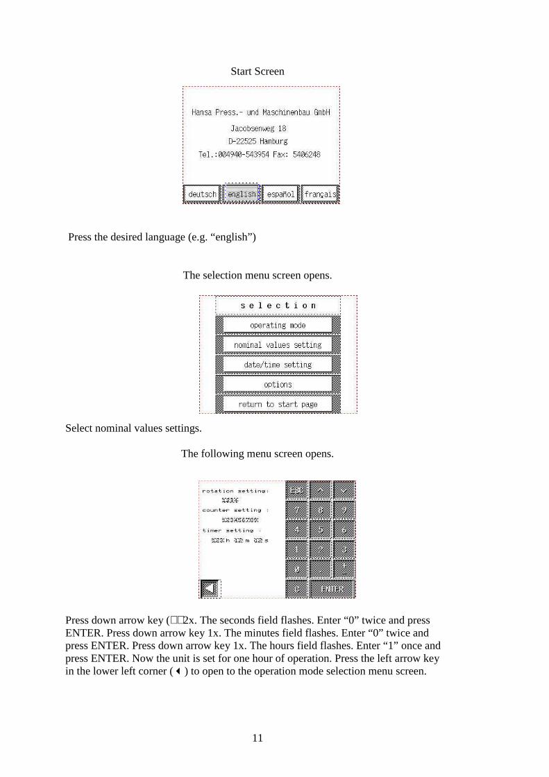
The selection menu screen opens.
Select operation mode.
The operation mode menu screen opens.
Select timer without FC.
The “timer without FC” menu screen opens.
13
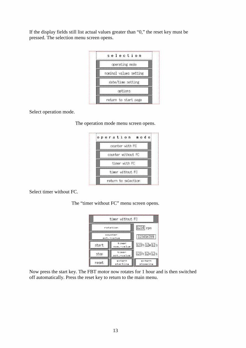
If the display fields still list actual values greater than “0,” the reset key must be pressed. The selection menu screen opens.
Select operation mode.
The operation mode menu screen opens.
Select timer without FC.
The “timer without FC” menu screen opens.
Now press the start key. The FBT motor now rotates for 1 hour and is then switched off automatically. Press the reset key to return to the main menu.
14
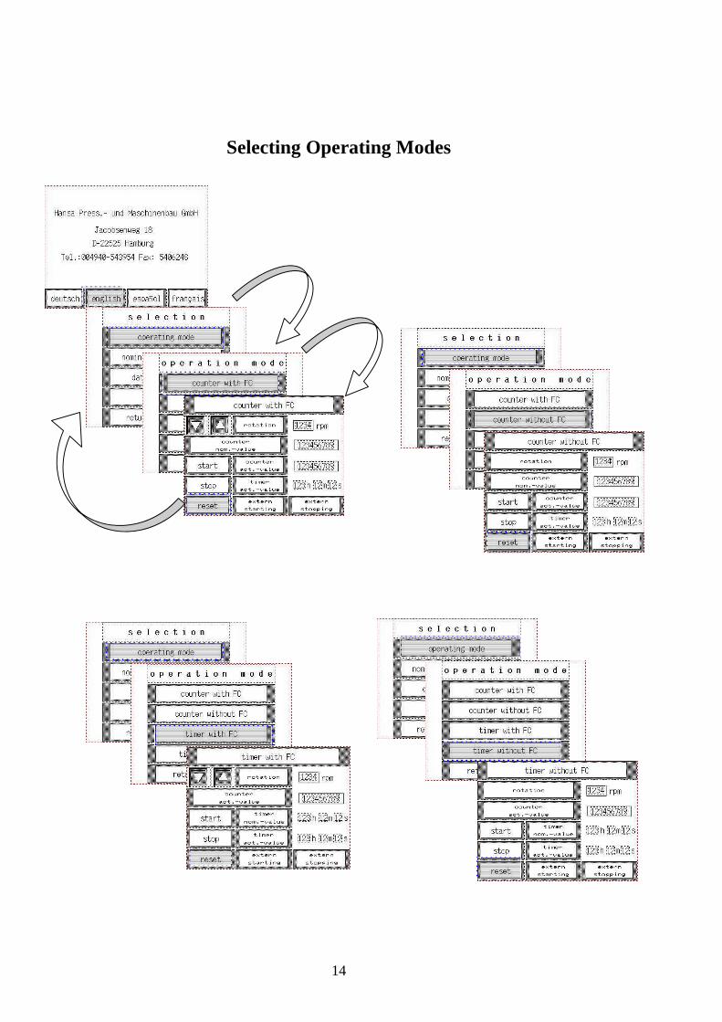
Selecting Operating Modes
15
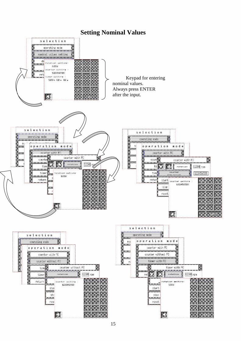
Setting Nominal Values
Keypad for entering nominal values. Always press ENTER after the input.
16
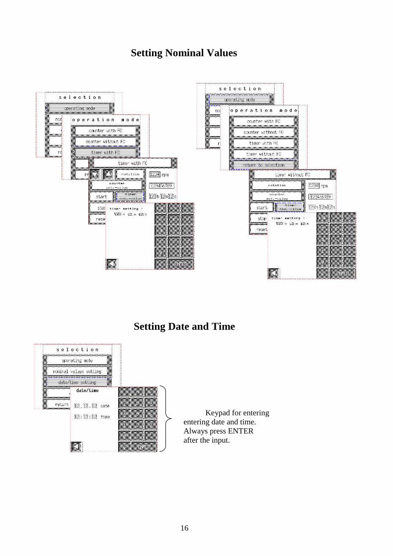
Setting Nominal Values
Setting Date and Time
Keypad for entering entering date and time. Always press ENTER after the input.
17
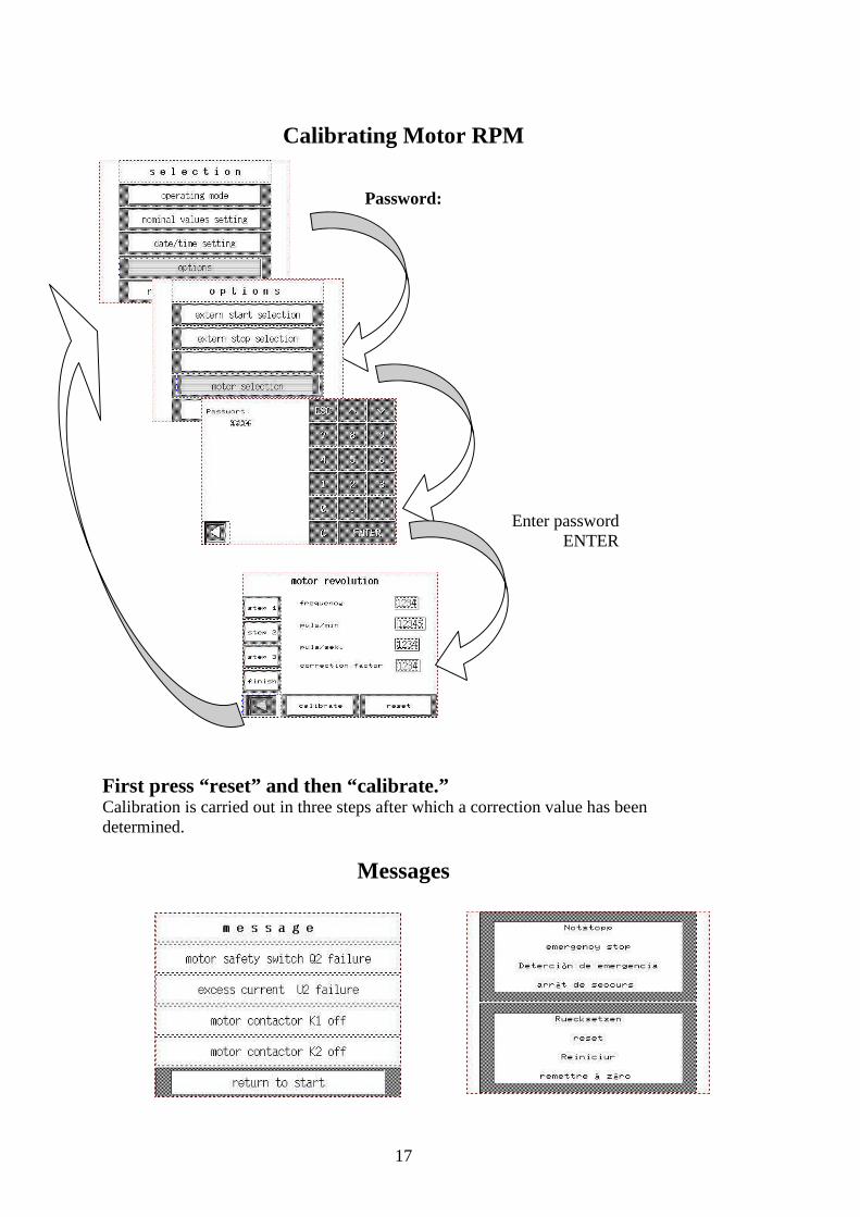
Calibrating Motor RPM
Password:
Enter password ENTER
First press “reset” and then “calibrate.” Calibration is carried out in three steps after which a correction value has been determined.
Messages
18
2.4. Adjusting the sliding weight (Item 30): The load-level can be adjusted by moving the sliding weight (Item 30) on the weight beam (Item 24). By means of a point in the index crank (Item 46) the sliding weight (10 kg) can be set to the required load. By gently moving the sliding weight (Item 30) to and fro on the weight beam (Item 24) you centre the index-crank point (Item 46), thereby positioning the weight precisely and obtaining the precise load required. 2.5. Fitting the extra weights (Items 36 & 37): By fitting the two extra weights supplied (Items 36 & 37) it is possible to expand the load range. Fit them by pushing them on to the sliding weight (Item 30) and then securing/positioning them with the fixing-screw (Item 15). The corresponding load sequences will be found in Appendix A-1. 2.6. Ball holder: 2.6.1. Inserting and mounting the ball holder: Caution: risk of injury Attach the ball holder to the spindle only with the machine switched off (pushbutton S0 = "Machine off".) Switch off FBT motor (pushbutton: "Machine OFF"). Press new test ball firmly into the ball holder. With the test ball loaded, press the ball holder firmly into the spindle and tap home with a copper hammer to ensure firm seating.
19
Caution: When inserted, the ball holder must stand not more than 0.75 mm and not less than 0.50 mm proud of the spindle. Before inserting it in the spindle, free the clamping surface of the ball holder of foreign bodies, since otherwise impact-free movement (at most 0.03 mm) of the ball and thus sound results cannot be expected. Unserviceable ball holders must be replaced with new ones immediately. Caution: risk of injury Never put your hand in the spindle’s working area while the spindle is rotating. 2.6.2. Removing the ball holder: Caution: risk of injury Remove the ball holder only with the machine switched off (pushbutton S0 = "Machine OFF"). Switch off FBT motor (pushbutton S0 = "Machine OFF"). When the spindle has stopped moving, relieve the ball cup of load by pressing down the release lever. The ball holder in the spindle is released together with the gripped balls using the ejector supplied (Item 9). Release is effected by inserting the ejector into the spindle cross-slot and then angling it. Caution: Do not remove ball holder by knocking it out of the spindle: this will damage the spindle mounting. With the drift punch (Item 18) the ball can be removed from the ball holder on the opening provided for the purpose in the mounting plate.
20
2.7. Ball cup (Item 10): The ball cup (with fitted pressure plate (Item 12)) is loaded by inserting three test balls. Place locking-ring (Item 11) on the balls loaded into the ball cup with the ground conical face downwards. The conical locking-ring centres the test balls in the ball cup. Secure the three test balls by tightening the lock-nut (Item 13). Insert the squared end of the ball cup into the mounting plate and with the special spanner supplied screw down the lock-nut very tightly, so that the balls are clamped immovably in place. The large forces which occur in the welding process would result in destruction of the pressure plate and locking-ring if the balls too were rotated. Then charge the ball cup with the oil to be tested. Pour into the ball cup only enough of the oil to be tested to bring the oil level about 3 mm above the three clamped-in test balls (approx. 7.5 cm3). Test balls: Only 12.700 G 20 balls to DIN 5401 made of anti-friction bearing steel 100 Cr6(W3) with Material No. 1.3505 and with Rockwell C hardness of 64+/-1 may be used. Use of these balls only is categorical. Balls made from a different material or with different hardness yield non-comparable results and thus flawed test results. A new set of 4 steel balls should be used for each test. 2.7.1. Loading the ball cup: Before the ball cup is loaded, the measuring arm must always be coupled to the support arm with the brace supplied (Item 38). Position ball-holder ball centrally on the ball cup containing the test balls and the oil to be tested. Then put the ball-cup cone (Item 34) in the pan (Item 41) in the turntable (Item 21). By pivoting the release lever (Item 32) downwards reduce the weight load until the three test balls in the ball cup and the one test ball in the ball holder are under the full load.
21
Loading by raising the release lever must be done SLOWLY and CAREFULLY, since otherwise indentations appear in the balls greater than those due to the test load. This applies in particular to high loads of 500 to 1000 kg, since at these loads the stress on individual parts, above all the knife-edge bearing, is very high anyway. After loading, place the release lever securely in the holder (Item 47) mounted on the housing. NB: A test does not start until the motor is switched on, i.e. until the load is applied. 2.7.2. Relieving the load on the ball cup: When the motor (spindle) has stopped, take the load off the ball cup/balls by pressing the release lever down. Take ball cup out and detach using the squared end in the mounting plate. 2.8. Types of test: The running-time depends on the purpose of the test, i.e. whether the tests are long-time or welding tests. In the case of loads at the weld threshold an electronic automatic system takes over switching-off of the machine if welding occurs. Types of test and events taking place during the tests: see Section 3.
22
3. Test specifications: 3.1. Types of test 3.1.1. To be attended to before every test: For each test a new set of balls must be fitted and the ball cup charged with fresh oil. Before the 3 balls are placed in the cup and the single ball in the holder and spindle the parts must be cleaned of all residues, above all the ball cup with locking-ring and the ball holder. Then lightly grease the thread of the ball cup, since there is otherwise risk of it seizing when tightened. Caution: If the parts mentioned above have not been cleaned, abraded particles left behind could falsify the result. To create constant conditions for comparison it is necessary for the oil always to be tested at the same temperature and that the ball cup itself is not excessively heated. If necessary, 2 ball cups should be used in the tests alternately. Before a test series starts, the four-ball tester must be run at no load for 10 minutes so that the spindle mounting reaches the required operating temperature. 3.1.2. Standard short-time tests For testing oils the short-time test will generally be used, with a run-time of 1 minute. The advantages of this are that the oil can be tested in the shortest time, that specific surface-pressures can be used, e.g. those occurring on the teeth of heavily loaded geared mechanisms, and that a low level of total heat occurs which prevents harmful effects on the test balls and holding elements, e.g. reduction in the hardness of these parts. To determine the wear curve a series of these short-time tests is run with the lubricant to be tested in which the loads applied to the ball cup vary. For oils with lower extreme-pressure lubricating properties the changes in
23
load applied are smaller, e.g. 140, 160, 180, 200 kg etc.; for oils with higher extreme-pressure lubricating properties they can be larger, e.g. 300, 350, 400, 450 kg etc. By short-time tests the SHAPE OF THE ABRASION CURVE, the FRICTION COEFFICIENT, the CHANGE IN THE FRICTION COEFFICIENT, ABRASION-DELAY TIME and WELD THRESHOLD can be determined. These processes will be examined in greater detail below. 3.1.3. Long-time tests Long-term tests are performed to obtain some idea of the slowly proceeding wear (abrasion) which can occur with various lubricants under less heavy loads. In these tests a low load on the ball cup is preferable, which means that the test may take several hours. The loads in these tests are always below 40 kg. A level of 15 kg over a period of 60 minutes has proved expedient. Since the scale on the balance-arm does not permit a setting of 15 kg with the aid of the smaller sliding weight, a special weight of 1 kg or 2 kg must be used; this is suspended from the holding-notches of the 10-kg sliding weight. The upper row of digits must be divided by 10 in the case of the 1-kg weight and 5 in the case of 2-kg one in order to give the actual value for the 4 steel balls. Test conditions for these tests have not been standardised. NB: Only weights with the same centre of gravity as the 10-kg sliding weight may be used. Weights between 1 and 10 kg are available as accessories.
24
3.1.4. Testing of materials: The four-ball tester also lends itself to testing materials. The characteristics of materials with respect to wear, friction coefficient, susceptibility to scuffing can for example be investigated if the same type of oil is used. NB: With the four-ball tester only the chemical composition is effective, not however its viscosity, since because of low slip velocity and the balls’ poor tangential cohesion no significant hydrodynamic forces can develop. For many materials balls cannot be obtained. In such cases pegs with spherical caps can be made; these should then be arranged on a circular plate in a manner imitating the position of the 3 clamped balls normally used. The circular plate can be repeatedly re-used once the pegs have been tapped out. The 4th ball located in the ball holder/spindle can also be replaced by a peg with screwed-on cap and put in the spindle instead of the ball holder. The peg must therefore be of tapered type in order to fit in the spindle aperture. 3.2. Events taking place during tests: 3.2.1. Conditions at low loads: At low loads wear on the balls is exceptionally low. This is also evident if the friction moment, i.e. friction coefficient, is measured/recorded. The friction coefficient will in this case remain the same and in general be between 0.05 and 0.1. No friction peaks occur. Only on start-up is a brief increase in friction observed (see Fig. 1).
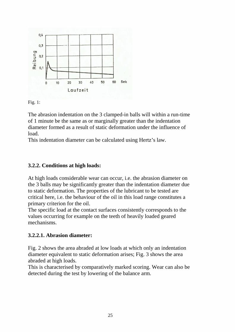
25
Fig. 1: The abrasion indentation on the 3 clamped-in balls will within a run-time of 1 minute be the same as or marginally greater than the indentation diameter formed as a result of static deformation under the influence of load. This indentation diameter can be calculated using Hertz’s law. 3.2.2. Conditions at high loads: At high loads considerable wear can occur, i.e. the abrasion diameter on the 3 balls may be significantly greater than the indentation diameter due to static deformation. The properties of the lubricant to be tested are critical here, i.e. the behaviour of the oil in this load range constitutes a primary criterion for the oil. The specific load at the contact surfaces consistently corresponds to the values occurring for example on the teeth of heavily loaded geared mechanisms. 3.2.2.1. Abrasion diameter: Fig. 2 shows the area abraded at low loads at which only an indentation diameter equivalent to static deformation arises; Fig. 3 shows the area abraded at high loads. This is characterised by comparatively marked scoring. Wear can also be detected during the test by lowering of the balance arm.

26
Fig. 2 Fig.3 If an equilibrium is established during the test, i.e. no more wear is occurring, the balance arm stops falling. With a highly-geared SLAVE POINTER and a graduated arc the approximate level and temporal course of abrasion can therefore be visualised even during the test. During the 1-minute test several friction peaks and therefore several abrasion periods may occur. In most cases, however, no further abrasion occurs during the last 30 seconds, so that the abrasion diameter can be taken as a MEASURE OF THE DEPTH OF ABRASION. The quantity of steel abraded from the ball at the bottom is approximately the abrasion diameter to the power of four. The abrasion diameter is measured with a Brinell magnifier or measuring microscope, the 3 balls being placed for the purpose on a plate fitted with location holes. Appendix A-2 describes an add-on unit with measuring microscope which is available as an accessory. The advantage of this accessory is that the balls can remain clamped in the ball cup and be measured there. To enable abrasion to be recorded as accurately as possible, the abrasion diameter of all 3 balls is measured in the direction of friction (d1) and perpendicular to the direction of friction (d2). From diameters d1 and d2 the average diameter for each ball can be calculated and from that the average for all 3 balls. This average is termed AVERAGE ABRASION DIAMETER. It can have values from 0.2 to 5 mm.
27
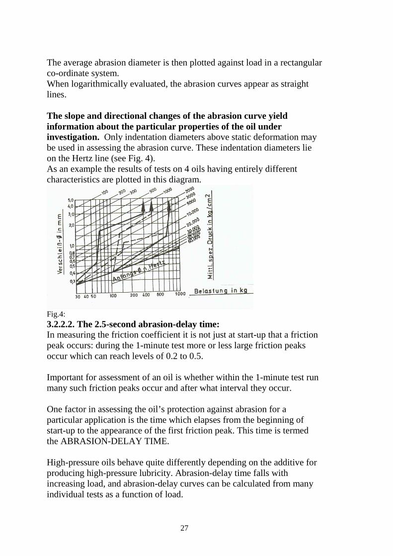
The average abrasion diameter is then plotted against load in a rectangular co-ordinate system. When logarithmically evaluated, the abrasion curves appear as straight lines. The slope and directional changes of the abrasion curve yield information about the particular properties of the oil under investigation. Only indentation diameters above static deformation may be used in assessing the abrasion curve. These indentation diameters lie on the Hertz line (see Fig. 4). As an example the results of tests on 4 oils having entirely different characteristics are plotted in this diagram.
Fig.4: 3.2.2.2. The 2.5-second abrasion-delay time: In measuring the friction coefficient it is not just at start-up that a friction peak occurs: during the 1-minute test more or less large friction peaks occur which can reach levels of 0.2 to 0.5. Important for assessment of an oil is whether within the 1-minute test run many such friction peaks occur and after what interval they occur. One factor in assessing the oil’s protection against abrasion for a particular application is the time which elapses from the beginning of start-up to the appearance of the first friction peak. This time is termed the ABRASION-DELAY TIME. High-pressure oils behave quite differently depending on the additive for producing high-pressure lubricity. Abrasion-delay time falls with increasing load, and abrasion-delay curves can be calculated from many individual tests as a function of load.
28
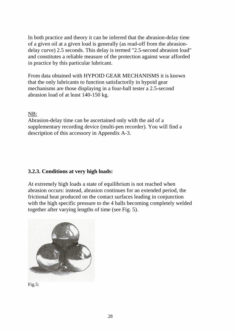
In both practice and theory it can be inferred that the abrasion-delay time of a given oil at a given load is generally (as read-off from the abrasion-delay curve) 2.5 seconds. This delay is termed "2.5-second abrasion load" and constitutes a reliable measure of the protection against wear afforded in practice by this particular lubricant. From data obtained with HYPOID GEAR MECHANISMS it is known that the only lubricants to function satisfactorily in hypoid gear mechanisms are those displaying in a four-ball tester a 2.5-second abrasion load of at least 140-150 kg. NB: Abrasion-delay time can be ascertained only with the aid of a supplementary recording device (multi-pen recorder). You will find a description of this accessory in Appendix A-3. 3.2.3. Conditions at very high loads: At extremely high loads a state of equilibrium is not reached when abrasion occurs: instead, abrasion continues for an extended period, the frictional heat produced on the contact surfaces leading in conjunction with the high specific pressure to the 4 balls becoming completely welded together after varying lengths of time (see Fig. 5).
Fig.5:

29
In by far the majority of cases this welding together starts at the beginning of the 1-minute test. The next load down is then generally designated the oil’s high-pressure lubricity. At this load the oil therefore just withstands a run of 1 minute without the balls welding together. It denotes therefore a figure of 320/340 kg, that the oil concerned just withstands the 1-minute run at a load of 320 kg and at 340 kg leads to welding.1 The FBT welding point is not for all oils a criterion for an oil’s serviceability specifically in heavily-loaded gear mechanisms. If necessary, the oil’s abrasion characteristics must also be investigated on the FBT.
1 The meaning of this passage is obscure. With only slight alteration of the German it could read "A figure of 320/340 kg denotes therefore that the oil concerned……" (Tr.).
30
4. Servicing: 4.1. Spindle mounting: Bearing clearance is zero and self-compensating. The spindle mounting has been greased with a EXTREME-PRESSURE GREASE and is maintenance-free. 4.2. Ball holder (Item 3): The integral ball holder, loaded with approx. 400 kg, must project not more than 0.75 and not less than 0.5 mm. If these limits are exceeded, a new ball holder must be used. Wear on the ball holder is apparent if the holder can be inserted too far into the spindle so that the holder rests at the base of the spindle. This causes the ball to be insufficiently gripped and to slide in the ball holder proportionately. This is visibly evident in tangential rubbing marks on the surface of the ejected spindle ball. As far as possible the spindle and ball in it must run impact-free. Damaged or fouled ball holders lead to the upper ball running out-of-true and thus to inaccurate measurements. From time to time, therefore, check that the spindle is running concentrically and without play. To do this use a dial gauge and check for spherical shape (radial deviation on the ball not more than 0.03 mm). NB: Before the balls are placed in the ball holder and the loaded ball holder placed in the spindle, all residues must be removed from these parts. In addition the spindle nose must also be cleaned.

31
4.3. Ball cup: From time to time the pressure plate and locking-ring must be inspected for development of indentation/scoring and replaced if these parts are excessively affected. If the pressure plate is defective it must be turned over or replaced. Before the ball cup is fitted all residues must be cleaned from ball cup, locking-ring, balls and lock-nut. The pressure plate and locking-ring should be inspected regularly for indentations/scoring and replaced if excessively affected. 4.4. Centre and knife-edge bearings: Each bearing should be regularly inspected. Particularly when the machine is operated at high loads the knife-edge bearing must be regularly greased and checked for firm seating.
5. Transport and setting-up: 5.1. Installation site: The four-ball tester must be set up in a dust-free and quiet (vibration-free) place (testing laboratory). Furthermore, the area must be very well-lit so that visual inspections can be accurately performed. 5.2. Ground quality: The four-ball tester does not need a special underbase. Do however observe the ground’s load-bearing capacity. If in doubt you should consult a statics expert.
32
5.3. Floor-space required: Four-ball testers supplied with a table need floor space approx. 1200 x 700 mm. The floor space required is otherwise dependent on the undertable used. For each four-ball tester there must be unobstructed access to the front and sufficient space for loading the weight beam. 5.4. Mechanical installation: NB: Always comply with the relevant accident-prevention regulations and other generally recognised safety rules. Wear protective clothing (helmet, gloves, safety boots). Do not lift four-ball tester higher than necessary. Remaining under a lifted four-ball tester is prohibited. Assembly work on the four-ball tester must be done with the master switch in the OFF "0" position. 5.4.1. Installing the housing (Item 1): The housing of the four-ball tester must be secured to a firm base (e.g. concrete pedestal, base-frame) with four bolts in the housing’s four through-holes. To obtain sound test results and unimpeded movement of the weight beam the housing must be installed perpendicularly (verification with a spirit level is sufficient). Four-ball testers complete with undertable: Position the housing (Item 1) and pedestal on the undertable. Position the housing so that the release lever (Item 32) is to be fitted on the left side of the table. Then secure housing and pedestal to the undertable with four bolts. Caution: danger of crushing Do not reach your hand under the housing or pedestal of the four-ball tester during assembly.
33
Then align the table surface horizontally (by adjusting the threaded feet), in order to obtain sound test results and unimpeded movement of the weight beam. Caution: danger of crushing Do not reach your hand under the table of the four-ball tester. 5.4.2. Installing the support for recording devices (Item 19): Secure the support for recording devices to the housing (Item 1) with two M10 x 40 hexagon bolts (Item 87) and two washers to DIN 125, B10 (Item 73). 5.4.3. Weight beam (Item 24): 5.4.3.1. Installing the weight beam (Item 24): Feed weight beam with fitted balancing weight (Item 43) through the opening in the side of the housing, below the fitted release lever (Item 32). The weight beam’s fitted balancing weight must be on the same side as the release lever. Place the knife-edge pins (Item 25) carefully in the knife-edge bearings (Item 26, inside the housing). Handle the knife edges of the weight beam very gently. In particular avoid damaging the tips by jarring or allowing them to fall into the knife-edge bearings, since otherwise the knife-edge geometry will be damaged. Sound test results cannot be obtained with a damaged knife-edge bearing. Caution: danger of cutting Knife-edges on the weight beam are very sharp and can cause cuts/incised wounds. Never therefore fit (transport) the weight beam without protective gloves.
34
5.4.3.2. Counterbalancing the weight beam: You will always receive your four-ball tester with the weight beam counterbalanced. If however you want to re-counterbalance the weight beam of your four-ball tester (because different cups are to be used) or merely check its balancing, then please note: The weight beam must be in equilibrium with pushrod, ram, turntable, ball cup incl. balls and also the specified quantity of oil, but without the sliding weight. Counterbalancing is effected by moving the balancing weight. Caution: risk of injury Undo set screw (Item 79) only to move the balancing weight (Item 43) on the weight beam (Item 24). Make sure that the balancing weight is always securely fitted. At loads from 300 kg upwards the weight beam must be inclined upwards at an angle of about 2-3º with the balls inserted. To adjust this angle the pan should be removed from the ram using the drift punch and suitable shim inserted between pan and ram. 5.4.4. Installing the pushrod (Item 22), ram (Item 20), bearing (Item 64) and turntable (Item 21): When the weight beam has been installed, place the pushrod (Item 22) on the weight beam through the hole in the base of the spindle’s working area (NB: pushrod is self-centring). Feed the ram (Item 20) into the hole over the pushrod, so that the pushrod presses centrally on the ram hole on the fitted pan (Item 23). Place ball thrust bearing (Item 64) on the fitted ram. Bed turntable (Item 21) with pressed-in pan (Item 41) rotatably on ball thrust bearing.
35
5.4.5. Installing the sliding weight (Item 30): Slide the 10-kg sliding weight (Item 30) on to the weight beam (Item 24) so that the index crank (31) points away from the housing. Move the point of the index crank (Item 46) to the desired position (see FBT Load Table). By gently moving the sliding weight (Item 30) to and fro on the weight beam (Item 24) you centre the point of the index crank (Item 46), so obtaining the exact weight position. 5.4.6. Fitting the extra weights (Items 36 & 37): Additionally fitting the two extra weights supplied (Items 36 & 37) enables the load range to be expanded. Fit the extra weights (Items 36 & 37) by pushing them on to the sliding weight (Item 30) and then securing/positioning them with a fixing bolt (Item 15). 5.4.7. Fitting the base for the control and monitoring unit (Group 7): Unless fitted already, secure the base (Group 7) for the control and monitoring unit (Group 8) to the undertable (Group 3) with four bolts. 5.4.8. Fitting the control and monitoring unit (Group 7): Secure the housing of the control and monitoring unit (Group 7) to the base (Group 7) with four bolts. 5.5. Electrical installation: Caution: All connections must be made by a qualified electrician. For connected loads please refer to the circuit diagram.
36
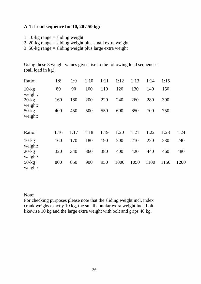
A-1: Load sequence for 10, 20 / 50 kg: 1. 10-kg range = sliding weight 2. 20-kg range = sliding weight plus small extra weight 3. 50-kg range = sliding weight plus large extra weight Using these 3 weight values gives rise to the following load sequences (ball load in kg): Ratio: 1:8 1:9 1:10 1:11 1:12 1:13 1:14 1:15
10-kg weight:
80 90 100 110 120 130 140 150
20-kg weight:
160 180 200 220 240 260 280 300
50-kg weight:
400 450 500 550 600 650 700 750
Ratio: 1:16 1:17 1:18 1:19 1:20 1:21 1:22 1:23 1:24
10-kg weight:
160 170 180 190 200 210 220 230 240
20-kg weight:
320 340 360 380 400 420 440 460 480
50-kg weight:
800 850 900 950 1000 1050 1100 1150 1200
Note: For checking purposes please note that the sliding weight incl. index crank weighs exactly 10 kg, the small annular extra weight incl. bolt likewise 10 kg and the large extra weight with bolt and grips 40 kg.
37
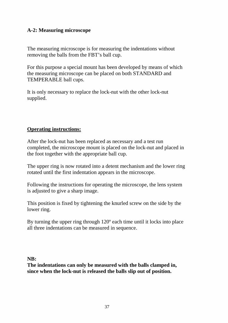
A-2: Measuring microscope The measuring microscope is for measuring the indentations without removing the balls from the FBT’s ball cup. For this purpose a special mount has been developed by means of which the measuring microscope can be placed on both STANDARD and TEMPERABLE ball cups. It is only necessary to replace the lock-nut with the other lock-nut supplied. Operating instructions: After the lock-nut has been replaced as necessary and a test run completed, the microscope mount is placed on the lock-nut and placed in the foot together with the appropriate ball cup. The upper ring is now rotated into a detent mechanism and the lower ring rotated until the first indentation appears in the microscope. Following the instructions for operating the microscope, the lens system is adjusted to give a sharp image. This position is fixed by tightening the knurled screw on the side by the lower ring. By turning the upper ring through 120º each time until it locks into place all three indentations can be measured in sequence. NB: The indentations can only be measured with the balls clamped in, since when the lock-nut is released the balls slip out of position.

38
A-3: Description of the Tractiv force dynamometer The tractiv force dynamometer enables the measurement of torques during the abrasion test, as well as the measurement to the wear delay. The technical data are to be inferred enclosed operating instructions Erstelldatum: 17.03.06