Embed Size (px)
Citation preview

Operating InstructionsVEGAMET 625
Double channel HART signal conditioning instrument
Document ID:28970
Signalconditioning instruments
and communication

Contents
1 About this document
1.1 Function. . . . . . . . . . . . . . . . . . . . . . . . . . . . . . . . . . 4
1.2 Target group . . . . . . . . . . . . . . . . . . . . . . . . . . . . . . 4
1.3 Symbolism used. . . . . . . . . . . . . . . . . . . . . . . . . . . . 4
2 For your safety
2.1 Authorised personnel . . . . . . . . . . . . . . . . . . . . . . . . 5
2.2 Appropriate use . . . . . . . . . . . . . . . . . . . . . . . . . . . . 5
2.3 Warning about misuse . . . . . . . . . . . . . . . . . . . . . . . 5
2.4 General safety instructions . . . . . . . . . . . . . . . . . . . . 5
2.5 Safety label on the instrument . . . . . . . . . . . . . . . . . . 6
2.6 CE conformity . . . . . . . . . . . . . . . . . . . . . . . . . . . . . 6
2.7 Safety instructions for Ex areas . . . . . . . . . . . . . . . . . 6
2.8 Overfill protection according to WHG . . . . . . . . . . . . . 6
2.9 Environmental instructions. . . . . . . . . . . . . . . . . . . . . 6
3 Product description
3.1 Configuration . . . . . . . . . . . . . . . . . . . . . . . . . . . . . . 7
3.2 Principle of operation . . . . . . . . . . . . . . . . . . . . . . . . 8
3.3 Operation. . . . . . . . . . . . . . . . . . . . . . . . . . . . . . . . . 8
3.4 Packaging, transport and storage . . . . . . . . . . . . . . . 9
4 Mounting
4.1 General instructions . . . . . . . . . . . . . . . . . . . . . . . . . 10
4.2 Mounting instructions . . . . . . . . . . . . . . . . . . . . . . . . 10
5 Connecting to power supply
5.1 Preparing the connection . . . . . . . . . . . . . . . . . . . . . 12
5.2 Connection procedure. . . . . . . . . . . . . . . . . . . . . . . . 12
5.3 Wiring plan. . . . . . . . . . . . . . . . . . . . . . . . . . . . . . . . 14
6 Setup with the integrated indicating and adjustment unit
6.1 Adjustment system . . . . . . . . . . . . . . . . . . . . . . . . . . 16
6.2 Setup procedure. . . . . . . . . . . . . . . . . . . . . . . . . . . . 17
6.3 Menu schematic . . . . . . . . . . . . . . . . . . . . . . . . . . . . 28
7 Setup with PACTware
7.1 Connecting the PC . . . . . . . . . . . . . . . . . . . . . . . . . . 36
7.2 Parameter adjustment with PACTware . . . . . . . . . . . . 39
7.3 Setup web server/e-mail, remote enquiry . . . . . . . . . . 40
8 Application examples
8.1 Level measurement in a cylindrical tank with overfillprotection/dry run protection . . . . . . . . . . . . . . . . . . . 41
8.2 Weir control of a water power station . . . . . . . . . . . . . 42
8.3 Interface measurement with VEGAFLEX 67 . . . . . . . . 44
8.4 Pump control 1/2 (running time controlled) . . . . . . . . . 46
8.5 Tendency recognition . . . . . . . . . . . . . . . . . . . . . . . . 48
2 VEGAMET 625 • Double channel HART signal conditioning instrument
Contents28970-EN-091116

8.6 Flow measurement . . . . . . . . . . . . . . . . . . . . . . . . . . 49
9 Maintenance and fault rectification
9.1 Maintenance . . . . . . . . . . . . . . . . . . . . . . . . . . . . . . 52
9.2 Rectify malfunctions . . . . . . . . . . . . . . . . . . . . . . . . . 52
9.3 Instrument repair . . . . . . . . . . . . . . . . . . . . . . . . . . . 55
10 Dismount
10.1 Dismounting steps . . . . . . . . . . . . . . . . . . . . . . . . . . 56
10.2 Disposal . . . . . . . . . . . . . . . . . . . . . . . . . . . . . . . . . 56
11 Supplement
11.1 Technical data . . . . . . . . . . . . . . . . . . . . . . . . . . . . . 57
11.2 Overview applications/functionality . . . . . . . . . . . . . . . 61
11.3 Dimensions . . . . . . . . . . . . . . . . . . . . . . . . . . . . . . . 62
Supplementary documentation
Information:
Supplementary documents appropriate to the ordered version comewith the delivery. You can find them listed in chapter "Productdescription".
VEGAMET 625 • Double channel HART signal conditioning instrument 3
Contents28970-EN-091116

1 About this document
1.1 Function
This operating instructions manual provides all the information youneed for mounting, connection and setup as well as importantinstructions for maintenance and fault rectification. Please read thisinformation before putting the instrument into operation and keep thismanual accessible in the immediate vicinity of the device.
1.2 Target group
This operating instructions manual is directed to trained qualifiedpersonnel. The contents of this manual should be made available tothese personnel and put into practice by them.
1.3 Symbolism used
Information, tip, note
This symbol indicates helpful additional information.
Caution: If this warning is ignored, faults or malfunctions canresult.Warning: If this warning is ignored, injury to persons and/or seriousdamage to the instrument can result.Danger: If this warning is ignored, serious injury to persons and/ordestruction of the instrument can result.
Ex applications
This symbol indicates special instructions for Ex applications.
l List
The dot set in front indicates a list with no implied sequence.
à Action
This arrow indicates a single action.
1 Sequence
Numbers set in front indicate successive steps in a procedure.
4 VEGAMET 625 • Double channel HART signal conditioning instrument
1 About this document28970-EN-091116

2 For your safety
2.1 Authorised personnel
All operations described in this operating instructions manual must becarried out only by trained specialist personnel authorised by the plantoperator.
During work on and with the device the required personal protectiveequipment must always be worn.
2.2 Appropriate use
VEGAMET 625 is a universal signal conditioning instrument and powersupply unit for connection of two HART sensors.
You can find detailed information on the application range in chapter"Product description".
Operational reliability is ensured only if the instrument is properly usedaccording to the specifications in the operating instructions manual aswell as possible supplementary instructions.
For safety and warranty reasons, any invasive work on the devicebeyond that described in the operating instructions manual may becarried out only by personnel authorised by the manufacturer. Arbitraryconversions or modifications are explicitly forbidden.
2.3 Warning about misuse
Inappropriate or incorrect use of the instrument can give rise toapplication-specific hazards, e.g. vessel overfill or damage to systemcomponents through incorrect mounting or adjustment.
2.4 General safety instructions
This is a high-tech instrument requiring the strict observance ofstandard regulations and guidelines. The user must take note of thesafety instructions in this operating instructions manual, the country-specific installation standards as well as all prevailing safetyregulations and accident prevention rules.
The instrument must only be operated in a technically flawless andreliable condition. The operator is responsible for trouble-freeoperation of the instrument.
During the entire duration of use, the user is obliged to determine thecompliance of the required occupational safety measures with thecurrent valid rules and regulations and also take note of newregulations.
VEGAMET 625 • Double channel HART signal conditioning instrument 5
2 For your safety28970-EN-091116

2.5 Safety label on the instrument
The safety approval markings and safety tips on the device must beobserved.
2.6 CE conformity
This device fulfills the legal requirements of the applicable EC
guidelines. By attaching the CE mark, VEGA provides a confirmationof successful testing. You can find the CE conformity declaration in thedownload area of www.vega.com.
2.7 Safety instructions for Ex areas
Please note the Ex-specific safety information for installation andoperation in Ex areas. These safety instructions are part of theoperating instructions manual and come with the Ex-approvedinstruments.
2.8 Overfill protection according to WHG
In Germany the WHG (Water Resource Act) stipulates an overfillprotection for systems that deal with substances hazardous to water.An appropriately certified sensor is the prerequisite for suchprotection. The VEGAMET 625 fulfils the construction and testingprinciples for overfill protection systems. This is certified by the TÜV(Technical Control Board) statement "PP 5003/09". You can downloadthis document from our homepage under "Downloads - Approvals -
Signal conditioning instruments - Overfill protection".
2.9 Environmental instructions
Protection of the environment is one of our most important duties. Thatis why we have introduced an environment management system withthe goal of continuously improving company environmental protection.The environment management system is certified according to DIN
EN ISO 14001.
Please help us fulfil this obligation by observing the environmentalinstructions in this manual:
l Chapter "Packaging, transport and storage"
l Chapter "Disposal"
6 VEGAMET 625 • Double channel HART signal conditioning instrument
2 For your safety28970-EN-091116
3 Product description
3.1 Configuration
The scope of delivery encompasses:
l VEGAMET 625 signal conditioning instrumentl Terminal socketl Coded pins and bridgesl RS232 modem connection cable (optional)l Documentation
- this operating instructions manual- Supplementary instruction 30325 "RS232/Ethernet connec-
tion" (optional)- Supplementary instructions manual 30768 "Modbus-TCP,
VEGA ASCII protocol" (optional)- Ex-specific "Safety instructions" (with Ex-versions)- if necessary, further certificates
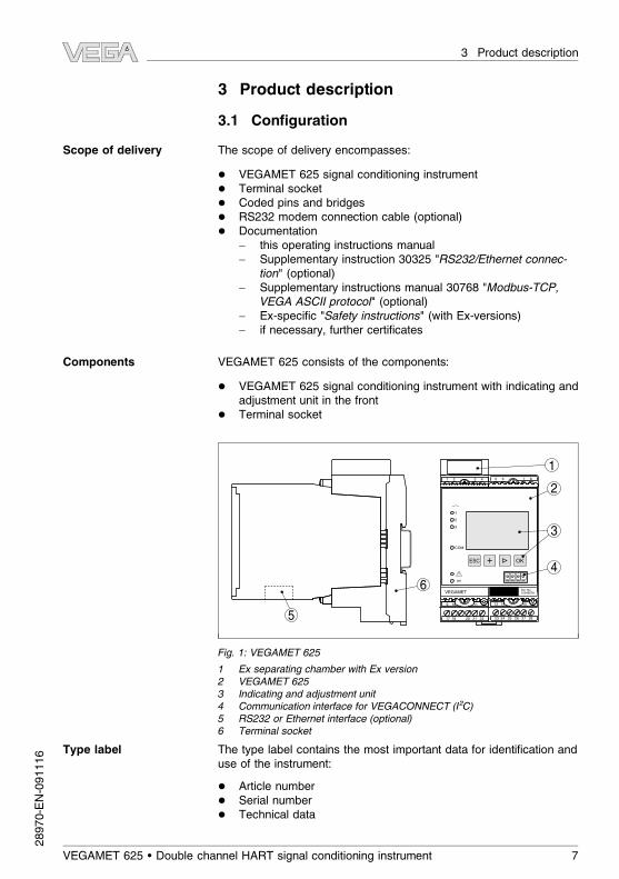
VEGAMET 625 consists of the components:
l VEGAMET 625 signal conditioning instrument with indicating andadjustment unit in the front
l Terminal socket
VEGAMET
1 2 3 4
9 10 11 12
17 18 20 21 22
5 6 7 8
13 14 15 16
23 24 25 26 27 28
Ser. No.
12345678
on
OKESC
COM
3
2
1
2
3
4
1
6
5
Fig. 1: VEGAMET 625
1 Ex separating chamber with Ex version
2 VEGAMET 625
3 Indicating and adjustment unit
4 Communication interface for VEGACONNECT (I²C)
5 RS232 or Ethernet interface (optional)
6 Terminal socket
The type label contains the most important data for identification anduse of the instrument:
l Article numberl Serial numberl Technical data
Scope of delivery
Components
Type label
VEGAMET 625 • Double channel HART signal conditioning instrument 7
3 Product description28970-EN-091116
l Article numbers, documentation
The serial number allows you to access the delivery data of theinstrument via www.vega.com, "VEGA Tools" and "serial number
search".
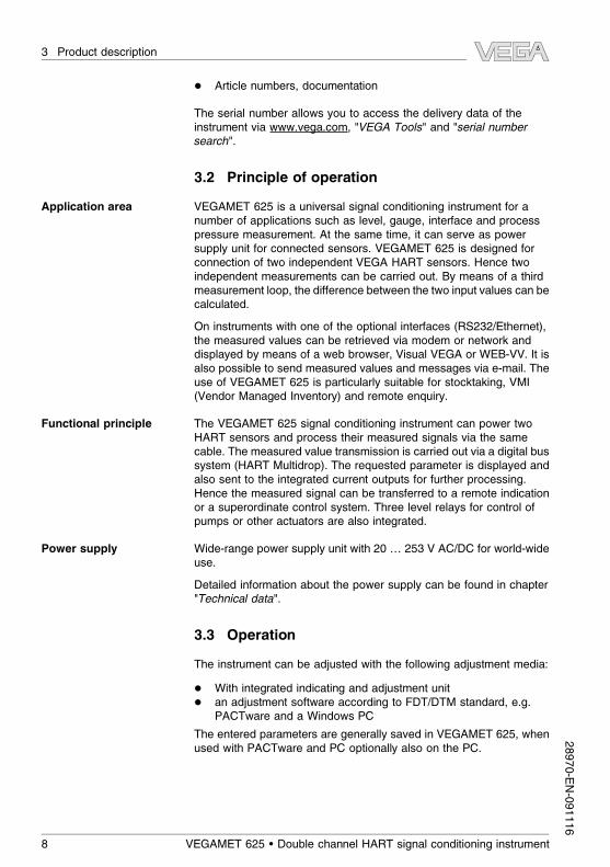
3.2 Principle of operation
VEGAMET 625 is a universal signal conditioning instrument for anumber of applications such as level, gauge, interface and processpressure measurement. At the same time, it can serve as powersupply unit for connected sensors. VEGAMET 625 is designed forconnection of two independent VEGA HART sensors. Hence twoindependent measurements can be carried out. By means of a thirdmeasurement loop, the difference between the two input values can becalculated.
On instruments with one of the optional interfaces (RS232/Ethernet),the measured values can be retrieved via modem or network anddisplayed by means of a web browser, Visual VEGA or WEB-VV. It isalso possible to send measured values and messages via e-mail. Theuse of VEGAMET 625 is particularly suitable for stocktaking, VMI
(Vendor Managed Inventory) and remote enquiry.
The VEGAMET 625 signal conditioning instrument can power twoHART sensors and process their measured signals via the samecable. The measured value transmission is carried out via a digital bussystem (HART Multidrop). The requested parameter is displayed andalso sent to the integrated current outputs for further processing.Hence the measured signal can be transferred to a remote indicationor a superordinate control system. Three level relays for control ofpumps or other actuators are also integrated.
Wide-range power supply unit with 20 … 253 V AC/DC for world-wideuse.
Detailed information about the power supply can be found in chapter"Technical data".
3.3 Operation
The instrument can be adjusted with the following adjustment media:
l With integrated indicating and adjustment unitl an adjustment software according to FDT/DTM standard, e.g.
PACTware and a Windows PC
The entered parameters are generally saved in VEGAMET 625, whenused with PACTware and PC optionally also on the PC.
Application area
Functional principle
Power supply
8 VEGAMET 625 • Double channel HART signal conditioning instrument
3 Product description28970-EN-091116

Information:
When using PACTware and the corresponding VEGA DTM, additionalsettings can be carried out which are not or only partly possible withthe integrated indicating and adjustment unit. When using an adjust-ment software, you either need one of the integrated interfaces(RS232/Ethernet) or the interface converter VEGACONNECT.
Further instructions for setting up the web server and e-mail functionsare stated in the online help of PACTware or the VEGAMET 625 DTMsas well as the operating instructions manual "RS232/Ethernetconnection".
3.4 Packaging, transport and storage
Your instrument was protected by packaging during transport. Itscapacity to handle normal loads during transport is assured by a testaccording to DIN EN 24180.
The packaging of standard instruments consists of environment-friendly, recyclable cardboard. For special versions, PE foam or PE foilis also used. Dispose of the packaging material via specialisedrecycling companies.
Transport must be carried out under consideration of the notes on thetransport packaging. Nonobservance of these instructions can causedamage to the device.
The delivery must be checked for completeness and possible transitdamage immediately at receipt. Ascertained transit damage orconcealed defects must be appropriately dealt with.
Up to the time of installation, the packages must be left closed andstored according to the orientation and storage markings on theoutside.
Unless otherwise indicated, the packages must be stored only underthe following conditions:
l Not in the openl Dry and dust freel Not exposed to corrosive medial Protected against solar radiationl Avoiding mechanical shock and vibration
l Storage and transport temperature see chapter "Supplement -
Technical data - Ambient conditions"
l Relative humidity 20 … 85 %
Packaging
Transport
Transport inspection
Storage
Storage and transport
temperature
VEGAMET 625 • Double channel HART signal conditioning instrument 9
3 Product description28970-EN-091116

4 Mounting
4.1 General instructions
Each series 600 instrument consists of the actual signal conditioninginstrument as well as a plug-in socket for carrier rail mounting.Because it has protection class IP 30 or IP 20, the instrument isintended to be used in switching cabinets.
4.2 Mounting instructions
The plug-in socket is designed for carrier rail mounting according toEN 50022. The operating voltage is connected to terminals 17 and 18.
For neighbouring series 600 instruments it is possible to continueconnection L1 and N directly via the supplied bridges. Max. fiveinstruments can be connected through in this way.
Danger:
Looping through via bridges is only allowed for operating voltage(sockets L1 and N). The bridges must never be used with singleinstruments, at the end of a row of instruments or with other sockets. Ifthis rule is not heeded, there is a danger of coming into contact withthe operating voltage or causing a short circuit.
A VEGAMET 625 in Ex version is an auxiliary, intrinsically safeinstrument and may not be installed in explosion-endangered areas.
Before setup, the Ex separating chamber must be attached (as shownbelow) with Ex versions. Safe operation can be only ensured if theoperating instructions manual and the EG type approval certificate areobserved. VEGAMET 625 must not be opened.
All signal conditioning instruments are provided with different gapsdependent on type and version (mechanical coding).
The plug-in socket is provided with coded pins that can be inserted toprevent accidental interchanging of the various instrument types.
With a VEGAMET 625 in Ex version, the supplied coded pins (typecoded pin and Ex coded pin)must be inserted by the user according tothe below chart.
Installation possibilities
Mounting
Instrument coding
10 VEGAMET 625 • Double channel HART signal conditioning instrument
4 Mounting28970-EN-091116

A o
B o
C o
1 o
2 o
3 o
o
o
o
7 o
8 o
9 o
o
o
12 o
N
L1
VEGAA o
B o
C o
1 o
2 o
3 o
4 o
5 o
6 o
7 o
8 o
9 o
10 o
11 o
12 o
N
L1
VEGA
1 2 3 4 5 6 7 8
1
4 4
2
3
Fig. 2: Plug-in socket VEGAMET 625
1 Ex separating chamber
2 Ex coding with Ex version
3 Type coding for VEGAMET 624/625
4 Bridges for looping the operating voltage
VEGAMET 625 • Double channel HART signal conditioning instrument 11
4 Mounting28970-EN-091116

5 Connecting to power supply
5.1 Preparing the connection
Always keep in mind the following safety instructions:
l Connect only in the complete absence of line voltagel If overvoltages are expected, install overvoltage arresters
In hazardous areas you should take note of the appropriateregulations, conformity and type approval certificates of the sensorsand power supply units.
The voltage supply can be 20 … 253 V AC/DC, 50/60 Hz.
The operating voltage of VEGAMET 625 is connected with standardcable according to the national installation standards.
Standard two-wire cable can be used for connecting the sensors. Thescreening is absolutely necessary to ensure interference-free oper-ation with HART sensors.
Connect the cable screen on both ends to ground potential. In thesensor, the screen must be connected directly to the internal groundterminal. The ground terminal on the outside of the sensor housingmust be connected to the potential equalisation (low impedance).
If potential equalisation currents are expected, the screen connectionon the side of VEGAMET 625 must be made via a ceramic capacitor(e. g. 1 nF, 1500 V). The low frequency potential equalisation currentsare thus suppressed, but the protective effect against high frequencyinterference signals remains.
Take note of the corresponding installation regulations for Exapplications. In particular, make sure that no potential equalisationcurrents flow over the cable screen. In case of grounding on both sidesthis can be achieved by the use of a capacitor or a separate potentialequalisation.
5.2 Connection procedure
Note:
Before the actual setup, each HART sensors must be assigned anaddress (address range 1-15), (see chapter "Setup"). Address 0
(mode 4 … 20 mA) must not be used. When assigning an address,only one sensor should be connected to VEGAMET 625. If connectionis completed already, the wiring must be briefly cancelled foraddressing. Depending on the installation location of the sensors, itcan be advantageous to carry out this addressing before installing and
Note safety instructions
Take note of sa-
fety instructions
for Ex applica-
tions
Select power supply
Selecting connection
cable
Cable screening and
grounding
Select connec-
tion cable for Ex
applications
12 VEGAMET 625 • Double channel HART signal conditioning instrument
5 Connecting to power supply28970-EN-091116

connecting the sensors. This can be conveniently carried out e.g. inthe workshop. You just need a 24 Volt power supply as well as anindicating and adjustment module PLICSCOM or the adjustmentsoftware PACTware with VEGACONNECT.
Move on to electrical connection and proceed as follows:
1 Snap the socket without VEGAMET 625 onto the carrier rail
2 Connect sensor cable to terminal 1/2 (active input) or 3/4 (passiveinput), provide a screening
3 When using several sockets, loop the power supply by means ofbridges
4 Connect power supply (switched off) to terminal 17 and 18
5 If necessary, connect relays or other outputs
6 Insert VEGAMET 625 into the plug-in socket and screw it downtightly
Note:
If the addressing of the sensors has not yet been carried out, only onesensor must be connected. Addressing (see chapter "Setup") of thefirst sensor can then be carried out. Afterwards, the first sensor mustbe disconnected again and the next sensor connected and providedwith an address. Then all sensors can be connected and setup can bestarted.
Before setting up Ex versions, make sure the Ex separating chamber isplugged on the left housing side (above the sensor terminals). Thepins for type and Ex coding must also be inserted correctly.
Information:
l On the active input (terminal 1/2), VEGAMET 625 provides powerfor the connected sensors. Power supply and measurement dataare transmitted over the same two-wire cable. This mode isprovided for connection of measuring transducers without sepa-rate operating voltage (sensors in two-wire version).
l On the passive input (terminals 3/4), the sensors are not powered -
only the measured value is transmitted. This input is for sensorswith their own, separate operating voltage (sensors in four-wireversion). On a VEGAMET 625 in Ex version, the passive input isnot available due approval-technical reasons.
Note:
VEGAMET 625 is designed for connection of two HART sensors.Because they are accessed via different addresses in the HART
multidrop mode, both sensors are connected to the same sensor input.These are either terminals 1/2 (active input) or terminals 3/4 (passiveinput). Simultaneous mixed operation on active and passive input is
VEGAMET 625 • Double channel HART signal conditioning instrument 13
5 Connecting to power supply28970-EN-091116
not possible. The measured value transmission is carried out via thedigital HART signal. An analogue 4 … 20 mA transmission is notpossible. Because this is a digital bus system, only one two-wire cableshould lead to the two sensors. A distributor can be connected directlyin front of the sensors. As an alternative, the connection to the nextsensor can be continued via the second cable entry in the sensorhousing. The addressing of the sensors should be carried out beforeconnection, see chapter "Set up".
5.3 Wiring plan
17 18 19 20 21 22
9 10 11 12
1 2 3 4
23 24 25 26 27 28
13 14 15 16
5 6 7 8
L1 N
+ -
+ - + - + -
+ -
17 2 3
4 5 6
+ -
1211
13
8 9
10
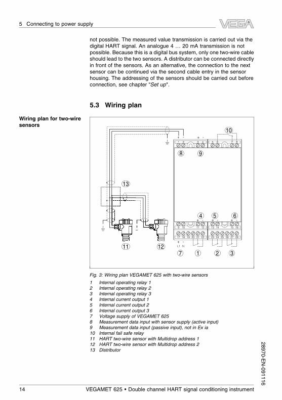
Fig. 3: Wiring plan VEGAMET 625 with two-wire sensors
1 Internal operating relay 1
2 Internal operating relay 2
3 Internal operating relay 3
4 Internal current output 1
5 Internal current output 2
6 Internal current output 3
7 Voltage supply of VEGAMET 625
8 Measurement data input with sensor supply (active input)
9 Measurement data input (passive input), not in Ex ia
10 Internal fail safe relay
11 HART two-wire sensor with Multidrop address 1
12 HART two-wire sensor with Multidrop address 2
13 Distributor
Wiring plan for two-wire
sensors
14 VEGAMET 625 • Double channel HART signal conditioning instrument
5 Connecting to power supply28970-EN-091116

17 18 19 20 21 22
9 10 11 12
1 2 3 4
23 24 25 26 27 28
13 14 15 16
5 6 7 8
L1 N
+ -
+ - + - + -
+ -
17 2 3
8 9
4 5 6
+ -
1211
14
13
10
Fig. 4: Wiring plan VEGAMET 625 with four-wire sensors
1 Internal operating relay 1
2 Internal operating relay 2
3 Internal operating relay 3
4 Internal current output 1
5 Internal current output 2
6 Internal current output 3
7 Voltage supply of VEGAMET 625
8 Measurement data input with sensor supply (active input)
9 Measurement data input (passive input), not in Ex ia
10 Internal fail safe relay
11 HART four-wire sensor with Multidrop address 1
12 HART four-wire sensor with Multidrop address 2
13 Distributor
14 Power supply for four-wire sensors
Wiring plan for four-wire
sensors
VEGAMET 625 • Double channel HART signal conditioning instrument 15
5 Connecting to power supply28970-EN-091116

6 Setup with the integrated indicating and
adjustment unit
6.1 Adjustment system
The integrated indicating and adjustment unit is used for measuredvalue display, adjustment and diagnosis of VEGAMET 625 as well asthe connected sensors. The indication and adjustment are carried outvia four keys and a clear, graphic-capable display with backgroundlighting. The adjustment menu with selectable language is clearlystructured and enables easy setup.
Certain adjustment options are not possible or only partially availablewith the integrated indicating and adjustment unit. These are e.g.settings for the e-mail server. For such applications, the use ofPACTware with appropriate DTMs is recommended.
Ser. No.12345678
on
OKESC
COM
3
2
1
3
6
5
7
4
1
2
Fig. 5: Indicating and adjustment elements
1 LC display
2 Adjustment keys
3 Communication interface for VEGACONNECT
4 Status indication operation
5 Status indication fail safe relay
6 Status indication interface activity
7 Status indication operating relay 1 - 3
l [OK] key:- Move to the menu overview- Confirm selected menu- Edit parameter- Save value
l [->] key to select:- menu change- list entry- Select editing position
Function
Indicating and adjust-
ment elements
Key functions
16 VEGAMET 625 • Double channel HART signal conditioning instrument
6 Setup with the integrated indicating and adjustment unit28970-EN-091116

l [+] key:- Change value of the parameter
l [ESC] key:- interrupt input- jump to the next higher menu
Note:
Approx. 10 minutes after the last pressing of a key, an automatic resetto measured value indication is triggered. Any values not confirmedwith [OK] will not be saved.
6.2 Setup procedure
Through parameter adjustment, the instrument is adapted to theindividual application conditions. Calibration of the measuring point isthe most important step and should always be carried out. A scaling ofthe measured value to the desired physical variable and unit, possiblyincluding a linearization curve, is often useful. The adaptation of therelay switching points or the setting of an integration time to smooth themeasured value are further standard adjustment options.
For instruments with Ethernet interface, the instrument must beprovided with an IP address and subnet mask suitable for theinstrument. As an alternative, addressing via DHCP and a host nameis also possible. If necessary, the e-mail/webserver can be alsoconfigured with PACTware.
Information:
When using PACTware and the corresponding VEGA DTM, additionalsettings can be carried out which are not or only partly possible withthe integrated indicating and adjustment unit. When using an adjust-ment software, you either need one of the integrated interfaces(RS232/Ethernet) or the interface converter VEGACONNECT.
Further instructions for setting up the web server and e-mail functionsare stated in the online help of PACTware or the VEGAMET 625 DTMsas well as the supplementary instructions manual "RS232/Ethernetconnection".
VEGAMET 625 can process measured values of more than one HART
sensor. The measured values are transmitted as digital HART signalsto the same cable (bus). An analogue 4 … 20 mA transmission is notpossible, the current is limited to 4 mA. An own, unambiguous address(address range 1-15) must be assigned to each connected sensor.This mode is also called HART multidrop mode. Address 0 (mode4 … 20 mA) must not be used.
Parameter adjustment
Set HART address
VEGAMET 625 • Double channel HART signal conditioning instrument 17
6 Setup with the integrated indicating and adjustment unit28970-EN-091116

Note:
When addresses are being assigned, only one sensor must beconnected on the bus. If this is not the case, no sensor can beaccessed and it is not possible to assign an address.
The addressing can be carried out directly on each HART sensor viathe respective adjustment unit or adjustment software. As analternative, the setting of the sensor address can be also carried outvia the VEGAMET menu under "Service - Sensor address" (seechapter "Setup procedure" under "Service - Change sensor address").
Sensor address
New address:
01
After being switched on, VEGAMET 625 first of all carries out a shortself-check. The following steps are carried out:
l Internal check of the electronicsl indication of the instrument type, firmware version as well as the
instrument TAG (instrument name)l The output signals jump briefly to the set fault value
After the assignment of the addresses to the sensors, the currentmeasured values will be displayed and outputted.
As requested, the measured value display shows the individualmeasurement loops separately or in a joint overview. The respectivedigital display value, the measurement loop designation (meas. loopTAG) and the unit are shown. With the separate presentation, ananalogue bar graph is also displayed and the measured values appearin bigger font size. By pushing the [>] key, you move between thedifferent indicating options.
Note:
Depending on the configuration and use of all measurement loops, thecycle time for the measured value transmission can take up to fiveseconds.
32.6%
TAG-No.1 ■
By pushing [OK] you move from the measured value indication to themain menu.
Switch on phase
Measured value indica-
tion/Main menu
18 VEGAMET 625 • Double channel HART signal conditioning instrument
6 Setup with the integrated indicating and adjustment unit28970-EN-091116

▶ Device settings
Measurement loops
Display
Diagnostics
Service
Info
With the initial setup, you should select all submenu items of "Devicesettings" and enter the correct settings.
à Select the menu item "Device settings" with [->] and confirm with[OK].
Under the menu item "Device settings", you can select the requestedapplication. For all level, gauge and differential measurements, theapplication "Standard" is correct.
If an interface measurement should be carried out with a VEGAFLEX
67, you have to choose the menu item "Interface measurement" asapplication. After the configuration of the inputs, the exact DK value forthe upper medium must be entered. For further information seechapter "Application examples".
Application
▶ Standard
Interface
à Select the requested application with [->] and save your settingwith [OK]. Finally change to the menu item "Input" with [->].
Because VEGAMET 625 has two inputs, the measurement loops mustbe assigned to the inputs. After the addresses of the HART sensorsare assigned, a list of the existing sensors can be prepared anddisplayed via "Sensor selection - Sensor search". Now you can assignthe requested sensor to each measurement loop.
Input 1
undefined
Change input?
For transmission, VEGAMET 625 must be informed which "Sensor
value" should be used for further processing. Depending on the sensortype this can be distance, pressure, interface or temperature. WhenHART sensors of other manufacturers are connected, the options PV
(Primary Value) and SV (Secondary Value) will be available. Theparameter to be transmitted is stated in the operating instructionsmanual of the respective sensor manufacturer.
Device settings - Appli-
cation
Device settings - Input
VEGAMET 625 • Double channel HART signal conditioning instrument 19
6 Setup with the integrated indicating and adjustment unit28970-EN-091116

à Allocate the requested inputs to the appropriate measurementloops, select the suitable sensor value and save your settings with[OK]. After the first setup, you can modify the inputs also under"Meas. loop - Input".
You can assign an unambiguous name to VEGAMET 625 via theDevice-TAG. This function is recommended when several instrumentsare implemented and a good documentation of larger systems isrequired.
Device-TAG
Device Name
à Enter the requested values via the appropriate keys and save yoursettings with [OK].
For instruments with Ethernet interface, the instrument must beprovided with an IP address/Subnet mask suitable for your network.Depending on the network, the adjustment of a gateway address isalso necessary. As an alternative, addressing via DHCP and a hostname is also possible. These specifications are available from yournetwork administrator. Keep in mind that your settings are onlyeffective after a restart of VEGAMET 625. Further information to thesenetwork parameters is available in the supplementary instructionsmanual "RS232/Ethernet connection" and in the online help of thecorresponding DTMs.
IP address
Fix IP address ▼
LAN/Internet
IP address:
192.168.200.200
Subnet mask:
255.255.255.0
Change?
à Enter the values via the appropriate keys and save your settingswith [OK]. Disconnect briefly the operating voltage so that themodified settings become effective.
Date and time can be entered in this menu item for instruments withintegrated RS232/Ethernet interface. These time settings are bufferedin case of power failure for approx. 3 days.
Device settings - Device-
TAG
Device settings - Host
Name/IP addr.
Device settings - Time/
Date
20 VEGAMET 625 • Double channel HART signal conditioning instrument
6 Setup with the integrated indicating and adjustment unit28970-EN-091116

Time/Date
8:40
28.09.2004
à Enter the values via the appropriate keys and save your settingswith [OK].
Because VEGAMET 625 has two inputs, the measurement loops mustbe assigned to the inputs. After the addresses of the HART sensorsare assigned, a list of the existing sensors can be prepared anddisplayed via the sensor search. Now you can assign the requestedsensor to each measurement loop.
For transmission, VEGAMET 625 must be informed which "Sensor
value" should be used for further processing. Depending on the sensortype this can be distance, pressure, interface or temperature. WhenHART sensors of other manufacturers are connected, the options PV
(Primary Value) and SV (Secondary Value) will be available. Theparameter to be transmitted is stated in the operating instructionsmanual of the respective sensor manufacturer.
Input ①
VEGAPULS (addr. 1)
Distance
Change input?
Via the parameter you inform VEGAMET 625 of the type ofmeasurement. The following options are available:
l Levell Process pressurel Temperaturel Difference (only with measurement loop 3)
l Interfacel Universal (for sensors of other manufacturers)
The third measurement loop is always a differential measurement loopcalculating the difference of the values of measurement loops 1 and 2
(optionally measurement loop 1-2 or 2-1).
Measured variable
Level ▼
Measurement loop - In-
put
Meas. loop - Parameter
VEGAMET 625 • Double channel HART signal conditioning instrument 21
6 Setup with the integrated indicating and adjustment unit28970-EN-091116

Information:
Keep in mind that some settings must be carried out individuallyseveral times, because they are specifically required for eachmeasurement loop. This applies e.g. to the single measurement loops,the displayed values in the display as well as the relay and currentoutputs.
The unit of measurement must be selected before starting theadjustment. Depending on the connected instrument this can be e.g.m(d), ft(d), bar, psi, °C or %.
Unit of measurement 1
m(d) ▼
The following illustrations and examples relate to the min./max.adjustment of a radar sensor.
Min. adjustment 1
0.00 %
≙
32.00 m(d)
9.245 m(d)
à With [OK] you prepare the percentage value for editing, with [->]
you set the cursor to the requested position. Set the requestedpercentage value with [+] and save with [OK]. The cursor jumpsnow to the distance value.
à Enter now the appropriate distance value in m [m(d)] (corre-sponding to the percentage value) for the empty vessel (e.g.distance from the sensor to the vessel bottom).
à Save your settings with [OK] and move to "Max. adjustment" with[->].
Max. adjustment 1
100.00 %
≙
0.000 m(d)
0.489 m(d)
à As described previously, enter now the percentage value for max.adjustment and confirm with [OK].
à Enter now the appropriate distance value in m [m(d)] (corre-sponding to the percentage value) for the full vessel. Keep in mindthat the max. level must be below the radar antenna.
à Finally save your settings with [OK], the adjustment is finished.
Meas. loop - Adjustment
22 VEGAMET 625 • Double channel HART signal conditioning instrument
6 Setup with the integrated indicating and adjustment unit28970-EN-091116

To suppress fluctuations in the measured value display, e.g. causedby an agitated product surface, an integration time can be set. Thistime can be between 0 and 999 seconds. Remember that the reactiontime of the entire measurement will then be longer and the sensor willreact to measured value changes with a delay. In general, a period of afew seconds is sufficient to smooth the measured value indication.
Damping 1
1 s
à Enter the requested parameters via the appropriate keys and saveyour settings with [OK].
A linearization is necessary for all vessels in which the vessel volumedoes not increase linearly with the level, e. g. with a cylindrical orspherical tank. Corresponding linearization curves are preprog-rammed for these vessels. They represent the correlation between thelevel percentage and vessel volume. By activating the appropriatecurve, the volume percentage of the vessel is displayed correctly. Ifthe volume should not be displayed in percent but e.g. in l or kg, ascaling can be also set.
Linearisation curve 1
linear▼
à Enter the requested parameters via the appropriate keys and saveyour settings with [OK].
Scaling means the conversion of the measured value into a certainparameter and unit. The indication can then show e.g. instead of thepercentage value, the volume in l. Indication values of max. -99999 to+99999 are possible.
Scaling: Unit 1
Mass▼
kg ▼
à Enter the requested parameters via the appropriate keys and saveyour settings with [OK].
Meas. loop - Damping
Meas. loop - Lineariza-
tion curve
Meas. loop - Scaling
VEGAMET 625 • Double channel HART signal conditioning instrument 23
6 Setup with the integrated indicating and adjustment unit28970-EN-091116

In this menu item you can enter an unambiguous designation for eachmeasurement loop, e.g. the measurement loop name or the tank orproduct designation. In digital systems and in the documentation oflarger plants, a singular designation should be entered for exactidentification of individual measurement points.
Measurement loop TAG 1
TAG-No. 1
à Enter the requested parameters via the appropriate keys and saveyour settings with [OK].
The relay and current outputs are arranged under "Outputs".With relayoutput, first of all the requested mode must be selected ("Overfill
protection" or "Dry run protection"). Additional modes such asswitching window and flow can be only adjusted via PACTware andDTM.
l Overfill protection: Relay is switched off when the max. level isexceeded (safe currentless condition), relay is switched on againwhen the level falls below the min. level (switch on point < switchoff point)
l Dry run protection: Relay is switched off when the level fallsbelow the min. level (safe currentless condition), relay is switchedon again when the max. level is exceeded (switch on point >switch off point)
Relay operating mode 1
Overfill protection▼
à Enter now the switching points for switching the relay on and off.The parameter to which they refer can also be selected.
Rel. switching points 1
Basic meas. value:
Percent ▼
In the following window the reaction of the relay in case of failure canbe determined. Here you can define whether, in case of failure, theswitching condition of the relay remains unchanged or the relay isswitched off.
Meas. loop - Meas. loop
TAG
Meas. loop - Outputs -
Relay outputs
24 VEGAMET 625 • Double channel HART signal conditioning instrument
6 Setup with the integrated indicating and adjustment unit28970-EN-091116

The characteristics of the current outputs can be set to 0 … 20 mA,
4 … 20 mA or inverted. The reaction in case of failure can be alsoadapted to the requirements. The parameter to which they refer canalso be selected.
Current output 1
Basic meas. value: % ▼
Output mode: 4-20mA▼
Failure mode: 22 mA ▼
à Enter the requested parameters via the appropriate keys and saveyour settings with [OK].
In menu item "Display" you can adjust the requested indicating valuefor measurement loops 1 … 3. This is only possible when VEGA
sensors are used.
Displayed value
lin. percent ▼
à Enter the requested parameters via the appropriate keys and saveyour settings with [OK].
When the instrument displays a failure message, further information isavailable under the menu item "Diagnosis - Device status".
Sensor status
E008
Sensor not found
The service menu contains the following settings:
l Simulation of the measured valuel Resetl Set display languagel PIN to block the menu
à Enter the requested parameters via the appropriate keys and saveyour settings with [OK].
Meas. loop - Outputs -
Current outputs
Display
Diagnostics
Service
VEGAMET 625 • Double channel HART signal conditioning instrument 25
6 Setup with the integrated indicating and adjustment unit28970-EN-091116

There are two reset modes:
l Reset to default: despite of a few exceptions, all settings will bereset to default. Exceptions are: IP-addr., subnet mask, time,language.
l Reset to measurement loop: The selected measurement loop willbe deactivated. Use this function if there is no measured valueavailable on a measurement loop or its inputs so that the failuremessage caused can be suppressed.
Reset
Factory setting
Reset now?
Under this menu item you can assign and modify the HART addressesof the connected sensors.
Note:
When addresses are being assigned, only one sensor with the sameaddress must be connected on the bus. If this is not the case, thesensor cannot be accessed and it is not possible to assign an address.
Adjust in the menu item "Previous address" the actual HART addressof the requested sensor. The default setting of all supplied VEGA
sensors is always 00 (mode 4 … 20 mA).
Sensor address
Previous address:
00
After pushing the [->] key, you can assign the requested HART
address in the range of 01 - 15 in the menu "New address". Make surethat no address is assigned twice.
Sensor address
New address:
01
In the menu item "Info" the following information is available:
l Sensor type and serial numberl Date of manufacture and software versionl Date of last change using PC
Service - Reset
Service - Change sensor
address
Info
26 VEGAMET 625 • Double channel HART signal conditioning instrument
6 Setup with the integrated indicating and adjustment unit28970-EN-091116

l Device characteristicsl MAC address (with interface option Ethernet)
Additional adjustment and diagnostics options are available via theWindows software PACTware and the suitable DTM. Connection canbe made optionally via the built-in standard interface or one of theoptionally offered interfaces (RS232/Ethernet). Further information isavailable in chapter "Parameter adjustment with PACTware", in theonline help of PACTware or the DTM as well as in the operatinginstructions manual "RS232/Ethernet connection". An overview of thestandard functions and their adjustment options can be found inchapter "Functional overview" in the "Supplement".
Optional settings
VEGAMET 625 • Double channel HART signal conditioning instrument 27
6 Setup with the integrated indicating and adjustment unit28970-EN-091116

6.3 Menu schematic
Information:
Depending on the version and application, the highlighted menuwindows are not always available.
Device settings
▶ Device settings
Measurement loop
Display
Diagnostics
Service
Info
Application
Standard▼
Input ①
undefined
Change input?
Input ②
undefined
Change input?
Device-TAG
Device Name
Host name IP address
Fix IP address ▼
LAN/Internet
IP address:
192.168.200.200
Subnet mask:
255.255.255.0
Change?
Time/Date
15:34
18.09.2004
Communication protocol
VEGA protocol
WRA
Enable?
28 VEGAMET 625 • Double channel HART signal conditioning instrument
6 Setup with the integrated indicating and adjustment unit28970-EN-091116

Device settings - Input
▶ Device settings
Measurement loop
Display
Diagnostics
Service
Info
Input ①
undefined
Change input?
Input ①
▶ Sensor selection
Sensor value
Sensor selection ①
▶ Sensor search
Sensor list
Sensor search
Sensor search running
Sensor list ①
▶ VEGAPULS 61 addr 1
VEGAFLEX 61 addr 2
Meas. loop 1 and 2 - Input
Device settings
▶ Measurement loops
Display
Diagnostics
Service
Info
Measurement loops
▶ Meas. loop 1
Meas. loop 2
Meas. loop 3
Measurement loop
▶ Input
Measured variable
Operation
Damping
Linearisation curve
Input ①
VEGAPULS (addr. 1)
Distance
Change input?
Sensor info ①
Display now?
Sensor setting ①
Start sensor setting?
VEGAMET 625 • Double channel HART signal conditioning instrument 29
6 Setup with the integrated indicating and adjustment unit28970-EN-091116

Meas. loop 1 and 2 - Change input
Device settings
▶ Measurement loops
Display
Diagnostics
Service
Info
Measurement loops
▶ Meas. loop 1
Meas. loop 2
Meas. loop 3
Measurement loop
▶ Input
Measured variable
Operation
Damping
Linearisation curve
Input ①
VEGAPULS (addr. 1)
Distance
Change input?
Input ①
▶ Sensor selection
Sensor value
Sensor selection ①
▶ Sensor search
Sensor list
Sensor search
Sensor search…
Sensor assignment ①
VEGAPULS addr. 1 ▼
Meas. loop 3 - Change input
Device settings
▶ Measurement loops
Display
Diagnostics
Service
Info
Measurement loops
Meas. loop 1
Meas. loop 2
▶ Meas. loop 3
Meas. loop ③
▶ Input
Measured variable
Operation
Damping
Linearisation curve
Input variable ③
Sensor value
Input variable ③
Percent
Lin. percent
Scaled
▶ Sensor value
Meas. loop 1 and 2 - Parameter
Device settings
▶ Measurement loops
Display
Diagnostics
Service
Info
Measurement loops
▶ Meas. loop 1
Meas. loop 2
Meas. loop 3
Measurement loop
Input
▶ Measured variable
Operation
Damping
Linearisation curve
Measured variable
Level ▼
30 VEGAMET 625 • Double channel HART signal conditioning instrument
6 Setup with the integrated indicating and adjustment unit28970-EN-091116

Meas. loop 3 - Parameter
Device-TAG
▶ Measurement loops
Display
Diagnostics
Service
Info
Measurement loops
▶ Meas. loop 1
Meas. loop 2
Meas. loop 3
Measurement loop
Input
▶ Measured variable
Operation
Damping
Linearisation curve
Measured value ③
Difference ▼
Application ③
① - ②
Meas. loop - Adjustment
Device settings
▶ Measurement loops
Display
Diagnostics
Service
Info
Measurement loops
▶ Meas. loop 1
Meas. loop 2
Meas. loop 3
Measurement loop
Input
Measured variable
▶ Operation
Damping
Linearisation curve
Unit of measurement ①
m(d) ▼
Min. adjustment ③
0.00 %
≙
32.00 m(d)
9.245 m(d)
Max. adjustment ③
100.00 %
≙
0.000 m(d)
0.489 m(d)
Meas. loop - Damping
Device settings
▶ Measurement loops
Display
Diagnostics
Service
Info
Measurement loops
▶ Meas. loop 1
Meas. loop 2
Meas. loop 3
Measurement loop
Input
Measured variable
Operation
▶ Damping
Linearisation curve
Damping ①
1 s
VEGAMET 625 • Double channel HART signal conditioning instrument 31
6 Setup with the integrated indicating and adjustment unit28970-EN-091116

Meas. loop - Linearization curve
Device settings
▶ Measurement loops
Display
Diagnostics
Service
Info
Measurement loops
▶ Meas. loop 1
Meas. loop 2
Meas. loop 3
Measurement loop
Input
Measured variable
Operation
Damping
▶ Linearisation curve
Linearisation curve ①
linear▼
Meas. loop - Scaling
Device settings
▶ Measurement loops
Display
Diagnostics
Service
Info
Measurement loops
▶ Meas. loop 1
Meas. loop 2
Meas. loop 3
Input
Measured variable
Operation
Damping
Linearisation curve
▶ Scaling
Scaling: Unit ①
Mass ▼
kg
Scaling ①
0% = 0.5 kg
100% = 50.0 kg
Meas. loop - Meas. loop TAG
Device settings
▶ Measurement loops
Display
Diagnostics
Service
Info
Measurement loops
▶ Meas. loop 1
Meas. loop 2
Meas. loop 3
Input
Operation
Damping
Linearisation curve
Scaling
▶ Meas. loop TAG
Meas. loop TAG ①
TAG-No. 1
32 VEGAMET 625 • Double channel HART signal conditioning instrument
6 Setup with the integrated indicating and adjustment unit28970-EN-091116

Meas. loop - Output - Relay
Device settings
▶ Measurement loops
Display
Diagnostics
Service
Info
Measurement loops
▶ Meas. loop 1
Meas. loop 2
Meas. loop 3
Operation
Damping
Linearisation curve
Scaling
Meas. loop TAG
▶ Outputs
Outputs ①
▶ Relay outputs
Current outputs
Relay outputs ①
▶ Relay 1
Relay operating mode 1
Overfill protection
Basic meas. value rel. 1
Percent▼
Rel. switching points 1
Switching point OFF:
100 %
Switching point ON:
0 %
Relay failure mode 1
Switching status:
OFF ▼
Meas. loop - Outputs - Current outputs
Device settings
▶ Measurement loops
Display
Diagnostics
Service
Info
Measurement loops
▶ Meas. loop 1
Meas. loop 2
Meas. loop 3
Operation
Damping
Linearisation curve
Scaling
Meas. loop TAG
▶ Outputs
Outputs ①
Relay outputs
▶ Current outputs
Current outputs ①
▶ Current output 1
Current output ①
Basic meas. value: % ▼
Output mode: 4-20 mA▼
Failure mode: 0 mA ▼
VEGAMET 625 • Double channel HART signal conditioning instrument 33
6 Setup with the integrated indicating and adjustment unit28970-EN-091116

Display
Device settings
Measurement loops
▶ Display
Diagnostics
Service
Info
Displayed value
▶ 1 Percent ▼
2 Percent ▼
3 Scaled▼
Displayed value
▶ Meas. loop 1
Meas. loop 2
Meas. loop 3
Displayed value
▶ Percent ▼
lin. percent ▼
Scaled▼
Sensor value ▼
Diagnostics
Device settings
Measurement loop
Display
▶ Diagnostics
Service
Info
Sensor status
Meas. loop 1:E008
Meas. loop 2: OK
Meas. loop 3: OK
Show details?
Sensor status
E008
Sensor not found
Service
Device settings
Measurement loop
Display
Diagnostics
▶ Service
Info
Simulation
Start simulation▼
Reset
Factory setting
Reset now?
Language
Deutsch▼
PIN
Enable?
34 VEGAMET 625 • Double channel HART signal conditioning instrument
6 Setup with the integrated indicating and adjustment unit28970-EN-091116

Service - Simulation
Device settings
Measurement loops
Display
Diagnostics
▶ Service
Info
Simulation
Start simulation?
Simulation
▶ Meas. loop 1
Meas. loop 2
Both
Simulation
▶ Percent
Lin. percent
Sensor value
Simulation
Percent ①
+034.0 %
Service - Sensor address
Device settings
Measurement loops
Display
Diagnostics
▶ Service
Info
Sensor address
Change now?
Sensor address
Previous address:
00
Sensor address
New address:
01
Info
Device settings
Measurement loop
Display
Diagnostics
Service
▶ Info
Instrument type
VEGAMET 625
Serial number
12345678
Date of manufacture
03. February 2004
Software version
1.11.00
Last change using PC
26. September 2004
Device characteristics
Display now?
MAC address
00:30:87:D7:E8:E7
VEGAMET 625 • Double channel HART signal conditioning instrument 35
6 Setup with the integrated indicating and adjustment unit28970-EN-091116
7 Setup with PACTware
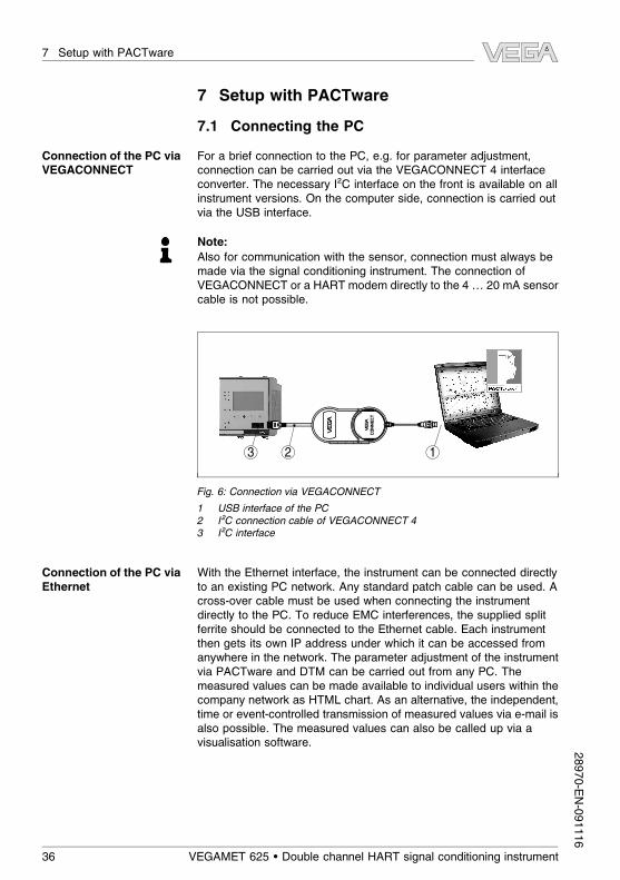
7.1 Connecting the PC
For a brief connection to the PC, e.g. for parameter adjustment,connection can be carried out via the VEGACONNECT 4 interfaceconverter. The necessary I²C interface on the front is available on allinstrument versions. On the computer side, connection is carried outvia the USB interface.
Note:
Also for communication with the sensor, connection must always bemade via the signal conditioning instrument. The connection ofVEGACONNECT or a HART modem directly to the 4 … 20 mA sensorcable is not possible.
OPEN
TW
IST
US
B
LOCK
123
Fig. 6: Connection via VEGACONNECT
1 USB interface of the PC
2 I²C connection cable of VEGACONNECT 4
3 I²C interface
With the Ethernet interface, the instrument can be connected directlyto an existing PC network. Any standard patch cable can be used. Across-over cable must be used when connecting the instrumentdirectly to the PC. To reduce EMC interferences, the supplied splitferrite should be connected to the Ethernet cable. Each instrumentthen gets its own IP address under which it can be accessed fromanywhere in the network. The parameter adjustment of the instrumentvia PACTware and DTM can be carried out from any PC. Themeasured values can be made available to individual users within thecompany network as HTML chart. As an alternative, the independent,time or event-controlled transmission of measured values via e-mail isalso possible. The measured values can also be called up via avisualisation software.
Connection of the PC via
VEGACONNECT
Connection of the PC via
Ethernet
36 VEGAMET 625 • Double channel HART signal conditioning instrument
7 Setup with PACTware28970-EN-091116

Note:
To contact the instrument, a corresponding IP address must beavailable in the instrument. Each instrument is preset to address192.168.200.200. Enter the address and subnet mask correspondingto your network directly via the keyboard. As an alternative, addressingis also possible via DHCP and a host name. Briefly interrupt theoperating voltage after each modification, then the instrument isaccessible via its IP address or host name everywhere in the network.In addition, these specifications must be entered in the DTM (seechapter "Parameter adjustment with PACTware").
2
3
1
Fig. 7: Connection of the PC via Ethernet
1 Ethernet interface of the PC
2 Ethernet connection cable (Cross-Over cable)
3 Ethernet interface
The RS232 interface is particularly suitable for easy modemconnection. External analog, ISDN and GSM modems with standardinterface can be used. The necessary RS232 modem connectioncable is included with the delivery. To reduce EMC interference, youshould mount the supplied ferrite bead on the RS232 modemconnection cable. Via a visualisation software, measured values canbe retrieved remotely and further processed. Alternatively, theautonomous time or event controlled transmission of measured valuesvia e-mail is also possible. Remote parameter adjustment of theinstrument and the connected sensors is also possible withPACTware.
Connection of the mo-
dem via RS232
VEGAMET 625 • Double channel HART signal conditioning instrument 37
7 Setup with PACTware28970-EN-091116
32
1
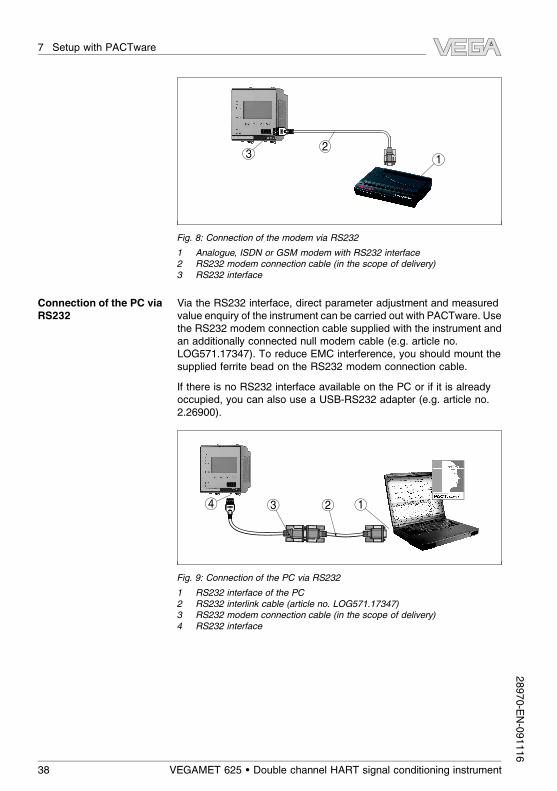
Fig. 8: Connection of the modem via RS232
1 Analogue, ISDN or GSM modem with RS232 interface
2 RS232 modem connection cable (in the scope of delivery)
3 RS232 interface
Via the RS232 interface, direct parameter adjustment and measuredvalue enquiry of the instrument can be carried out with PACTware. Usethe RS232 modem connection cable supplied with the instrument andan additionally connected null modem cable (e.g. article no.LOG571.17347). To reduce EMC interference, you should mount thesupplied ferrite bead on the RS232 modem connection cable.
If there is no RS232 interface available on the PC or if it is alreadyoccupied, you can also use a USB-RS232 adapter (e.g. article no.2.26900).
34 12
Fig. 9: Connection of the PC via RS232
1 RS232 interface of the PC
2 RS232 interlink cable (article no. LOG571.17347)
3 RS232 modem connection cable (in the scope of delivery)
4 RS232 interface
Connection of the PC via
RS232
38 VEGAMET 625 • Double channel HART signal conditioning instrument
7 Setup with PACTware28970-EN-091116

7.2 Parameter adjustment with PACTware
As an alternative to the integrated indicating and adjustment unit, theadjustment can be also carried out via a Windows PC. For this, theconfiguration software PACTware and a suitable instrument driver(DTM) according to the FDT standard are required. The actualPACTware version as well as all available DTMs are compiled in aDTM Collection. Furthermore, the DTMs can be integrated into otherframe applications according to the FDT standard.
Note:
To ensure that all instrument functions are supported, you shouldalways use the latest DTM Collection. Furthermore, not all describedfunctions are included in older firmware versions. The latest instrumentsoftware can be also downloaded from our homepage. A description ofthe update procedure is also available in the Internet.
Further setup steps are described in the operating instructions manual"DTM Collection/PACTware" attached to each DTM Collection andwhich can also be downloaded from the Internet. A detaileddescription is available in the online help of PACTware and the DTMsas well as in the supplementary instructions manual "RS232/Ethernetconnection".
Information:
To access the connected sensors, the addressing must be alreadycarried out, see chapter "Setup procedure - Set HART address". If theaddressing should be carried out now via PACTware, then also onlyone sensor must be connected.
When connecting via Ethernet, VEGAMET 625 must be provided witha suitable IP address and subnet mask. If the project setup is carriedout without assistant (online mode), IP address and subnet mask mustbe entered additionally in the DTM. Click in the project window with theright mouse key to the Ethernet DTM and choose "Add. functions -
Modify DTM addresses".
All device DTMs are available as a free-of-charge standard versionand as a full version that must be purchased. In the standard version,all functions for complete setup are already included. An assistent forsimple project configuration simplifies the adjustment considerably.Saving/printing the project as well as import/export functions are alsopart of the standard version.
In the full version there is also an extended print function for completeproject documentation as well as a save function for measured valueand echo curves. In addition, there is a tank calculation program aswell as a multiviewer for display and analysis of the saved measuredvalue and echo curves.
Prerequisites
Connection via Ethernet
Standard/Full version
VEGAMET 625 • Double channel HART signal conditioning instrument 39
7 Setup with PACTware28970-EN-091116

7.3 Setup web server/e-mail, remote enquiry
Setup and application examples of the web server, the e-mail functionsand the visualisation WEB-VV are specified in the supplementaryinstructions "RS232/Ethernet connection".
The connection via Modbus-TCP or ASCII protocol is described in anadditional supplementary instruction "Modbus-TCP, ASCII protocol".
Both supplementary instructions are attached to each instrument withRS232 or Ethernet interface.
40 VEGAMET 625 • Double channel HART signal conditioning instrument
7 Setup with PACTware28970-EN-091116

8 Application examples
8.1 Level measurement in a cylindrical tank with
overfill protection/dry run protection
The level is detected via a sensors and transmitted to the signalconditioning instrument by means of a 4 … 20 mA signal. Here, anadjustment is carried out converting the input value delivered by thesensor into a percentage value.
Due to the geometrical form of the cylindrical tank, the vessel volumedoes not increase linear with the level. This can be compensated byselecting the linearization curve integrated in the instrument. Thiscurve states the relation between percentage level and vessel volume.If the level should be displayed in litres, also a scaling must be carriedout. For this purpose, the linearized percentage value is converted intoa volume, for example with the unit litres.
The filling and emptying is controlled vial relay 1 and 2 integrated inthe signal conditioning instrument. During filling, relay mode "Overfill
protection" is adjusted. The relay is hence switched off (safecurrentless condition) when the max. level is exceeded, when fallingbelow the min. level it is switched on again (switch on point < switch offpoint). During emptying, mode "Dry run protection" is used. This relayis hence switched off when falling below the min. level (safecurrentless condition), when falling below the min. level it is switchedon again (switch on point > switch off point).
Rel. 1 Rel. 2
Rel. 1: 90%
Rel. 2: 5%
100%
0%
Fig. 10: Example of a level measurement, cylindrical tank
A cylindrical tank has a capacity of 10000 litres. The measurement iscarried out with a level sensor operating according to the principle ofthe guided microwave. The filling by a tank car is controll via relay 1
and a valve (overfill protection). The discharge is carried out via apump and is controlled by relay 2 (dry run protection). The max.
Functional principle
Example
VEGAMET 625 • Double channel HART signal conditioning instrument 41
8 Application examples28970-EN-091116

volume should be at 90 % level, these are 9538 litres with a standardvessel (according to bearing chart). The min. level should be adjustedto 5 %, this corresponds to 181 litres. The volume should be displayedin litres.
Carry out the adjustment in the signal conditioning instrument asdescribed in chapter "Setup steps". No additional adjustment musthence be carried out on the sensors. For the max. adjustment, fill thevessel up to the requested max. level and accept the actuallymeasured value. If this is not possible, the respective current value canbe entered alternatively. For the min. adjustment, empty the vessel upto the min. level or enter the respective current value.
To display the percentage level correctly, select under "Measurement
loop - Linearization curve" the entry "Cylindrical tank".
The display the volume in litres, you have to enter under "Measure-
ment loop - Scaling" as unit "Volume" in litres. Finally, the allocation iscarried out, in this example 100 % ≙ 10000 litres and 0 % ≙ 0 litres.
Percent is selected as reference value for the relays. The mode ofrelay 1 is set to overfill protection, relay 2 gets mode dry run protection.To ensure that the pump switches off in case of failure, the reaction incase of failure should be adjusted to switching status OFF. Theswitching points are adjusted as follows:
l Relay 1: Switch off point 90 %, switch on point 85 %
l Relay 2: Switch off point 5 %, switch on point 10 %
Information:
The switch on and off point of the relays must not be adjusted to thesame switching point because this would cause a permanent switchinon and off when this threshold is reached. To avoid this effect also withfluctuating product surface, a difference (hysteresis) of 5 % is usefulbetween the switching points.
8.2 Weir control of a water power station
A water power turbine must be protected against impurities in flowingwater. These impurities get stuck on the weir like on a screen. Themust be removed cyclacylly so that the max. flow is ensured. If thedegree of impurity is too high, the water level in front of the systemraises because the total water volume can no longer flow through. Thedifference between level in front of and after the weir is hence ameasure of the degree of impurity and can be used to control the weircleaner.
The water level in front of the weir (upstream water) and after the weir(downstream water) is measured each with a VEGAWELL 72 HART.
VEGAMET 625 generates the difference (h3) out of these two levels(measurement loop 3). If this difference is too high, a signal will be
Operation
Linearisation
Scaling
Relay
Functional principle
Example
42 VEGAMET 625 • Double channel HART signal conditioning instrument
8 Application examples28970-EN-091116

outputted by one of the integrated relays triggering the weir cleaning.Exemplary we assume a max. level of 2m, the weir cleaning should bestarted at a difference of 20 cm.
3
4
5h1
h3
1
2
Fig. 11: Differential measurement - weir control
1 Headwater
2 Tail water
3 Difference h3
4 Reference plane
5 max. level h1
The following steps are necessary:
l Selection of the application
- Select under "Device settings - Application" the entry "Stand-
ard" and confirm with [OK]. Via the [->] key you reach the nextstep.
l Addressing of the sensors
- Since both sensors are addressed via HART multidrop, first ofall the sensor addressing must be carried out (see chapter"Setup procedure")
- Connect sensor 1 for upstream water- Enter now under "Service - Change sensor address" in the
menu item "New address" HART address "01"
- Disconnect sensor 1 and connect sensor 2 for downstreamwater
- Assign HART address "02"
- Reconnect sensor 1
VEGAMET 625 • Double channel HART signal conditioning instrument 43
8 Application examples28970-EN-091116

l Assignment of the inputs and measurement loops
- Measurement loop 1 (upstream water): Start under"Measurement loops - Meas. loop 1 - Input - Change input 1 -
Sensor selection" the menu item "Sensor search". Withcorrect addressing, both sensors must be displayed. Selectthe first sensor with address 01
- Measurement loop 2 (downstream water): Go under"Measurement loops - Measurement loop 1 - Input - Change
input 1 - Sensor selection" to the menu item "Sensor list".
Select the second sensor with address 02
- Measurement loop 3 (difference): This measurement loopcalculates automatically without further settings the differencebetween upstream water and downstream water (measure-ment loop 1 minus measurement loop 2)
l Adjustment
- Measurement loop 1 (upstream water): Select under"Measurement loops -Meas. loop 1 - Adjustment" in the menuitem "Adjustment unit" the unit "m" (meter) and the density unit"1.000 kg/dm³". Enter under "Min. adjustment" 0.00 m andunder "Max. adjustment" the max. level in meter (h1) ein. I.e. inthe existing example 2 m
- Measurement loop 2 (downstream water): Carry out theadjustment with the same specifications as for measurementloop 1
- Measurement loop 3 (difference): The adjustment of theupstream water is taken over automatically (0 % ≙ 0.00m,
100% ≙ 2 m)
l Relay configuration
- Select under "Measurementloops - Meas. loop 3 - Outputs -
Relay otuputs - Relay 3 - Overfill protection - Percent" themenu item "Switching points relay 3". Enter for switching point"OFF" 10 % and for switching point "ON" 5 %. With thesesettings, the relay deenergizes at a difference of 20 cm andswitches on again at 10 cm. Hence the cleaning procedurestarts with a gauge difference of more than 20 cm and isrunning until the difference is again below 10 cm.
8.3 Interface measurement with VEGAFLEX 67
In an interface measurement, there are two different media which donot mix, e. g. water and oil or solvents. To detect the volume of bothproducts, it is necessary to detect the height of the upper liquid (level)and the interface between the two products. A VEGAFLEX 67 isnecessary as a transmitter which delivers the distance to the uppermedium as well as the distance to the interface. Via the adjustment inVEGAMET 625 the level, interface and layer thickness of the uppermedium can be calculated and displayed.
The following steps are necessary:
44 VEGAMET 625 • Double channel HART signal conditioning instrument
8 Application examples28970-EN-091116

l Selection of the application
- Select under "Device settings - Application" the entry "Inter-
face measurement" and confirm with [OK]. Via the [->] keyyou reach the next step.
l Assignment of the inputs and measurement loops
- Select "Input - Change input". Now the automatic sensorsearch is started and if connected correctly, VEGAFLEX 67
will be displayed. Take over the selection with [OK] and moveto the adjustment of the dielectric value with [->]. The inputvariables are assigned automatically to the following meas-urement loops:
- Meas. loop 1: Interface (level of the lower medium)
- Meas. loop 2: Level (total level of both products)- Meas. loop 3: Layer thickness (thickness of the upper
medium)
l Input of the DK value
- Enter here the exact dielectric value of the upper medium.
This value is then transferred automatically to VEGAFLEX 67.
Further information on the dielectric value are available in theoperating instructions manua of VEGAFLEX 67. For thisapplication, do not enter a dielectric value directly onVEGAFLEX 67, because this value will be overwrittenautomatically by VEGAMET 625
l Adjustment
- Each VEGAFLEX 67 is shipped with default settings. Thevalues of this adjustment are automatically tranferred toVEGAMET 625 during the setup of the interface measure-ment. Hence, manual adjustment is usually not necessary.Should the instrument require a special adjustment, thisadjustment can be carried out any time under "Measurement
loops - Adjustment". Keep in mind that this adjustment mustthen be carried out separately for all three measurementloops.
VEGAMET 625 • Double channel HART signal conditioning instrument 45
8 Application examples28970-EN-091116

TS
d1
h1
h2
d2
1
L2
L1
Fig. 12: Interface measurement
1 Reference plane
d1 Distance to the interface, meas. loop 1
d2 Distance to the level, meas. loop 2
TS Thickness of the upper medium (d1-d2), meas. loop 3 (displayed value)
h1 Height - Interface (displayed value)
h2 Height - Level (displayed value)
L1 Lower medium
L2 Upper medium
8.4 Pump control 1/2 (running time controlled)
Pump control 1/2 is used to control several pumps with the samefunction dependent on the previous running time. The pump with theshortest running time is always switched on and the pump with thelongest running time switched off. In case of higher requirements, allpumps can also run at the same time dependent on the enteredswitching points. Through this measure, a balanced utilization of thepumps is achieved and the reliability increased.
All relays with activated pump control are not assigned to a certainswitching point but are switched on or off depending on the operatingtime. The signal conditioning instrument selects the relay with theshortest operating time when the switch-on point is reached, and therelay with the longest operating time when the switch-off point isreached.
With this pump control, there are two different versions:
l Pump control 1: The upper switching point determines the switch-off point for the relay, whereas the lower switching pointdetermines the switch-on point
l Pump control 2: The upper switching point determines the switch-on point for the relay, whereas the lower switching pointdetermines the switch-off point
Functional principle
46 VEGAMET 625 • Double channel HART signal conditioning instrument
8 Application examples28970-EN-091116

Two pumps should empty the vessel when a certain level is reached.At 80 % filling, the pump with the shortest running time should switchon. If the level nevertheless increases, a second pump should switchon at 90 %. Both pumps should switch off again at 10 % filling.
Select in the DTM navigation section the menu items "Meas. loop -
Outputs - Relay".
l Set mode "Pump control 2" for relay 1 and 2.
l Enter the switching points for the concerned relays as follows:- Relay 1 upper switching point = 80.0 %
- Relay 1 lower switching point = 10.0 %
- Relay 2 upper switching point = 90.0 %
- Relay 2 lower switching point = 10.0 %
The function of pump control 2 is shown in detail in the followingdiagram. The previously described example is used as a basis.
Rel. 1: 80% On
On
Off
Off
On
Rel. 2: 90% On
Rel. 1, 2: 10% Off
10 30 20 20 15 t [h]5
Rel. 1
Rel. 2
Fig. 13: Example of a pump control 2
Switch on reaction of the pump control 2
After the signal conditioning instrument is switched on, the relays arestill in switched-off condition. Depending on the input signal and theswitch-on period of the individual relays, the following relay switchingconditions can occur after the start procedure:
l Input signal is higher than the upper switching point -> Relay withthe shortest switch on period is switched on
l Input signal is between lower and upper switching point -> Relayremains switched off
l Input signal is smaller than the lower switching point -> Relayremains switched off
Example
Setup
VEGAMET 625 • Double channel HART signal conditioning instrument 47
8 Application examples28970-EN-091116

8.5 Tendency recognition
The function of the tendency recognition is to recognize a definedchange within a certain time period and to transfer this information to arelay output.
The information for tendency recognition is generated out of themeasured value change per time unit. The output variable is alwaysthe measured value in percent. The function can be configured forrising and falling tendency. The actual measured value is determinedand summed with a sample rate of a second. After the max. reactiontime, the average value is generated out of this sum. The realmeasured value change results then of the newly calculated averagevalue less the previously calculated average value. If this differenceexceeds the defined percentage value, the tendency recognitionresponds and the relay deenergises.
Note:
The activation and configuration of the tendency recognition requiresPACTware with the suitable DTM. Setting parameters via theintegrated indicating and adjustment unit is not possible.
l Measured value change higher: Measured value change pertime unit, at which the tendency recognition should respond
l Max. reaction time: Time after which a new measured valuegeneration is carried out and the measured value change isrecalculated
l Hysteresis: is automatically always 10 % of the value of"Measured value change more than"
l Reaction in case of failure: In case of a failure, the relay goesinto the defined condition
Note:
After switching on or a failure, always two complete cycles must beexecuted until a measured value difference can be calculated and atendency can be outputted.
The level in a basin should be monitored on rising tendency. If the riseis higher than 25 % per minute, an additional emptying pumpt shouldbe switched on. The max. reaction time should be one minute. In caseof a probable failure, the pump should be switched off.
Select in the DTM navigation section the menu items "Meas. loop -
Outputs - Relay".
l E.g. set for relay 1 the mode "Rising tendency"
l Select under "Reaction in case of failure" the option "Switching
condition off"
l Enter the following values into the parameter fields:- Measured value more than 25 %/min.- Max. reaction time 1 min.
Functional principle
Principle of operation
Parameter
Example
Setup
48 VEGAMET 625 • Double channel HART signal conditioning instrument
8 Application examples28970-EN-091116

The function of the tendency recognition is shown in detail in thefollowing diagram. The previously described example is used as abasis.
t
t
m
t
m
t
m
t
m
120 180 240ON
OFF
60 [sec]
1 2 3 4
5
... ...
...
...
100
75
50
25
0
%
...
Fig. 14: Example for tendency recognition
1 Old average value = 25 %, new average value = 25 %
Difference < 25 % -> Relay ON
2 Old average value = 25 %, new average value = 37.5 %
Difference < 25 % -> Relay ON
3 Old average value = 37.5 %, new average value = 62.5 %
Difference = 25 % -> Relay OFF
4 Old average value = 62.5 %, new average value = 75 %
Difference < 25 % -> Relay ON
5 tm -> max. reaction time
8.6 Flow measurement
For flow measurement in open flumes, a contraction or standardisedflume must be used. Depending on the flow volume, this contractiongenerates a certain backwater. The flow can be determined from theheight of this backwater. The flow volume is outputted by anappropriate number of pulses on the relay or current output.
Depending on the type and version, each flume generates a differentbackwater. The data of the following flumes are available in theinstrument:
l Palmer-Bowlus-Flumel Venturi flume, trapezoidal weir, rectangular weirl V-Notch
Setup
The configuration of the flow measurement loop requires PACTwarewith the suitable DTMs. The example refers to a flow measurementwith a radar sensor. The following setup steps must be carried out:
l Selection of the parameter "Flow"l Carrying out adjustmentl Select flume (linearization)l Set scalingl Parameter adjustment of pulse outputs
Functional principle
Flume
VEGAMET 625 • Double channel HART signal conditioning instrument 49
8 Application examples28970-EN-091116

Select in the DTM window "Parameter" the option "Flow" with therequested unit of measurement.
Min. adjustment: Enter the suitable value for 0 %, i.e. the distancefrom the sensor to the medium as long as there is no flow. These are inthe following example 1.40 m.
Max. adjustment: Enter the suitable value for 100 %, i.e. the distancefrom the sensor to the medium, with the max. flow volume. This is inthe following example 0.80 m.
100% 0,80m (d)= 400m3/h=
0% 1,40m (d)= 0m3/h=
Fig. 15: Adjustment flow measurement with V-notch
Select in the DTM window "Linearization" the option "Flow" and thenthe used flume (in the above example V-notch).
Select in the DTM window "Scaling" under "Parameter" the option"Flow". Finally the allocation of a value must be carried out, i.e. the flowvolume is assigned to the 0 and 100 % value. As the last step, selectthe requested meas. unit. For above example: 0 % = 0 and 100 % =
400, meas. unit m³/h.
First of all decide if you want to use a relay and/or a current output. Inthe DTM window "Outputs" you can use any of the three outputs aslong as these are not yet used for other tasks.
Finally select under "Mode" (relay) or "Output characteristics" (currentoutput) the option "Flow volume pulse" or "Sampling pulse". Enterunder "Pulse output all" the flow volume after which a pulse should beoutputted (e.g. 400 m³ corresponds to one pulse per hour with a flowvolume of 400 m³/h).
In mode "Sampling pulse" an additional pulse is outputted after adefined time. This means that a timer is started after each pulse afterwhich another pulse is outputted. This applies only if already a pulsewas outputted after exceeding the flow volume.
Parameter - Flow
Operation
Linearisation curve
Scaling
Outputs
50 VEGAMET 625 • Double channel HART signal conditioning instrument
8 Application examples28970-EN-091116

Due to sludge at the bottom of the flume, it can happen that the min.adjustment originally carried out can no longer be reached. Thereforesmall quantities will continuously enter the flow volume detectiondespite the "empty" flume. The option "Min. flow volume suppression"
offers the possibility to suppress measured flow volumes below acertain percentage value for the flow volume detection.
VEGAMET 625 • Double channel HART signal conditioning instrument 51
8 Application examples28970-EN-091116

9 Maintenance and fault rectification
9.1 Maintenance
When used as directed in normal operation, VEGAMET 625 iscompletely maintenance free.
9.2 Rectify malfunctions
The operator of the system is responsible for taking suitable measuresto rectify malfunctions.
A maximum of reliability is ensured. Nevertheless, faults can occurduring operation. These may be caused by the following, e.g.:
l Measured value from sensor not correctl Power supplyl Interference on the cables
The first measures to be taken are to check the input and output signalas well as to evaluate the error messages via the display. Theprocedure is described below. Further comprehensive diagnostics canbe carried out on a PC with PACTware and the suitable DTM. In manycases, the causes can be determined in this way and faults rectified.
However, should these measures not be successful, call the VEGA
service hotline in urgent cases under the phone no. +49 1805 858550.
The hotline is available to you 7 days a week round-the-clock. Sincewe offer this service world-wide, the support is only available in theEnglish language. The service is free of charge, only the standardtelephone costs will be charged.
The signal conditioning instrument and the connected sensors arepermanently monitored during operation and the values entered duringparameter adjustment are checked for plausibility. If irregularitiesoccur or in case of incorrect parameter adjustment, a fault signal istriggered. In case of an instrument defect or line break/shortcircuit, afault signal is also triggered.
The fail safe relay deenergises in case of failure, the failure indicationlights and the current outputs react according to their configuredcontrol behaviour. In addition, one of the following fault messages isoutputted on the display.
? E003
l CRC error (error with self-check)
à Carry out a reset
Reaction when malfunc-
tions occur
Causes of malfunction
Fault rectification
24 hour service hotline
Fault message
52 VEGAMET 625 • Double channel HART signal conditioning instrument
9 Maintenance and fault rectification28970-EN-091116

à Send instrument for repair
? E007
l Sensor type not compatible
à Search for sensor again and allocate under "Meas. loop -
Input"
? E008
l Sensor not found
à Check connection of the sensor
à Check HART address of the sensor
? E011
l No HART sensor assigned
à Assign a sensor in the menu "Input"
? E013
l Sensor signals failure, no valid measured value
à Check sensor parameter adjustment
à Send sensor for repair
? E016
l Empty/full adjustment reversed
à Carry out a fresh adjustment
? E017
l Adjustment span too small
à Carry out a fresh adjustment and increase the distancebetween min. and max. adjustment
? E021
l Scaling span too small
à Carry out a fresh scaling, increase the distance between min.and max. scaling.
? E026
l Units of the input variable are different (only differentialmeasurement loop)
à Adapt the units of both
à Use sensors with the same input variable
VEGAMET 625 • Double channel HART signal conditioning instrument 53
9 Maintenance and fault rectification28970-EN-091116

? E030
l Sensor in boot phase
l value not valid
à Check sensor parameter adjustment
? E034
l EEPROM defective
à Carry out a reset
à Send instrument for repair
? E035
l EEPROM CRC error
à Carry out a reset
à Send instrument for repair
? E036
l Instrument software not executable (during software update orafter failed update)
à Wait until software update is finished
à Carry out another software update
? E053
l Sensor measuring range not read correctly
à HART communication error: Check sensor cable andscreening
? E062
l Pulse priority too small
à Increase under "Output" the entry "Pulse output all" so thatmax. one pulse per second is outputted.
? E110
l Relay switching points too close together
à Increase the difference between the two relay switching points
? E111
l Relay switching points interchanged
à Change relay switching points for "On/Off"
54 VEGAMET 625 • Double channel HART signal conditioning instrument
9 Maintenance and fault rectification28970-EN-091116

? E115
l Several relays not set to the same failure mode are assignedto the pump control
à All relays which are assigned to the pump control must be setto the same failure mode
? E116
l Several relays are assignef to the pump control which are notconfigured to the same mode
à All relays which are assigned to the pump control must be setto the same mode
Depending on the failure reason and measures taken, the stepsdescribed in chapter "Set up" must be carried out again, if necessary.
9.3 Instrument repair
If a repair is necessary, please proceed as follows:
You can download a return form (23 KB) from our Internet homepagewww.vega.com under: "Downloads - Forms and certificates - Repair
form".
By doing this you help us carry out the repair quickly and withouthaving to call back for needed information.
l Print and fill out one form per instrumentl Clean the instrument and pack it damage-proofl Attach the completed form and, if need be, also a safety data
sheet outside on the packagingl Please ask the agency serving you for the address of your return
shipment. You can find the respective agency on our websitewww.vega.com under: "Company - VEGA worldwide"
Reaction after fault rec-
tification
VEGAMET 625 • Double channel HART signal conditioning instrument 55
9 Maintenance and fault rectification28970-EN-091116

10 Dismount
10.1 Dismounting steps
Take note of chapters "Mounting" and "Connecting to power supply"
and carry out the listed steps in reverse order.
10.2 Disposal
The instrument consists of materials which can be recycled byspecialised recycling companies. We use recyclable materials andhave designed the electronics to be easily separable.
WEEE directive 2002/96/EG
This instrument is not subject to the WEEE directive 2002/96/EG andthe respective national laws. Pass the instrument directly on to aspecialised recycling company and do not use the municipal collectingpoints. These may be used only for privately used products accordingto the WEEE directive.
Correct disposal avoids negative effects to persons and environmentand ensures recycling of useful raw materials.
Materials: see chapter "Technical data"
If you have no possibility to dispose of the old instrumentprofessionally, please contact us concerning return and disposal.
56 VEGAMET 625 • Double channel HART signal conditioning instrument
10 Dismount28970-EN-091116

11 Supplement
11.1 Technical data
General data
Series Module unit with plug-in socket for mounting oncarrier rail 35 x 7.5 (EN 50022)
Weight 500 g (1.10 lbs)
Housing materials Noryl SE100, Lexan 920A
Socket materials Noryl SE100, Noryl SE1 GFN3
Connection terminals- Type of terminal Screw terminal
- Max. wire cross-section 1.5 mm² (AWG 16)
Power supply
Operating voltage 20 … 253 V AC, 50/60 Hz, 20 … 253 V DC
Max. power consumption 12 VA; 7.5 W
Sensor input
Number of sensors 2 x VEGA HART sensors
Type of input (selectable)1)
- Active input Sensor power supply by VEGAMET 625
- Passive input Sensor has own power supply
Measured value transmission- HART multidrop protocol digital for VEGA HART sensors
Terminal voltage- Non-Ex version approx. 28 V with 2 sensors (8 mA)
- Ex version approx. 18 V with 2 sensors (8 mA)
Current limitation approx. 45 mA (26 mA with Ex)
Adjustment range HART sensor- Adjustment range ± 10 % of sensor measuring range
- min. adjustment delta 0.1 % of sensor measuring range
Connection cable two-wire screened standard cable
Relay outputs
Quantity 3 x operating relay, 1 x fail safe relay
Function Switching relay for level or pulse relay for flow/sampling pulse
Contact Floating spdt
1) Selection is made via the terminals, a mixed operation active/passive is notpossible.
VEGAMET 625 • Double channel HART signal conditioning instrument 57
11 Supplement28970-EN-091116

Contact material AgSnO2, hard gold-plated
Turn-on voltage min. 10 mV DC, max. 250 V AC/DC
Switching current min. 10 µA DC, max. 3 A AC, 1 A DC
Breaking capacity min. 50 mW, max. 750 VA, max. 40 W DC (with U
less than 40 V)2)
Min. programmable switching hysteresis 0.1 %
- Fault signal (switch over) Switching status off; unchanged
Mode pulse output- Pulse length 350 ms
Current outputs
Quantity 3 x outputs
Function Current output for level or flow/sampling pulse
Range 0/4 … 20 mA, 20 … 0/4 mA
Resolution 1 µA
Max. load 500 Ω
Fault signal (switch over) 0; 3,6; 4; 20; 20,5; 22 mA, unchanged
Linearity error relating to 20 mA 0.08 %
Temperature error relating to 20 mA 0.005 %/K
Mode pulse output- Voltage pulse 12 V DC at 20 mA with load 600 Ω
- Pulse length 200 ms
Ethernet interface (optional)
Quantity 1 x, cannot be combined with RS232
Data transmission 10/100 MBit
Plug connection RJ45
Max. cable length 100 m (3937 in)
RS232 interface (optional)
Quantity 1 x, cannot be combined with Ethernet
Plug connection RJ45 (modem connection cable on 9-pole D-SUB
in the scope of delivery)
Max. cable length 15 m (590 in)
Indications
Measured value indication
2) If inductive loads or stronger currents are switched through, the gold platingon the relay contact surface will be permanently damaged. The contact isthen no longer suitable for switching low-level signal circuits.
58 VEGAMET 625 • Double channel HART signal conditioning instrument
11 Supplement28970-EN-091116

- graphic-capable LC display (50 x 25mm),
lightingdigital and quasianalogue indication
- Max. indicating range -99999 … 99999
LED displays- Status operating voltage 1 x LED green
- Status fault signal 1 x LED red
- Status operating relay 1/2/3 3 x LED yellow
- Status interface 1 x LED green
Operation
Adjustment elements 4 x keys for menu adjustment
PC adjustment PACTware with respective DTM
Ambient conditions
Ambient temperature -20 … +60 °C (-4 … +140 °F)
Storage and transport temperature -40 … +80 °C (-40 … +176 °F)
Electrical protective measures
Protection rating- Instrument IP 30
- Terminal socket IP 20
Overvoltage category II
Protection class II
Electrical separating measures
Reliable separation according to VDE 0106 part 1 between power supply, input and digital part- Reference voltage 250 V
- Isolation resistance 3.75 kV
Galvanic separation between relay output and digital part- Reference voltage 250 V
- Isolation resistance 4 kV
Potential separation between Ethernet interface and digital part- Reference voltage 50 V
- Isolation resistance 1 kV
Potential separation between RS232 interface and digital part- Reference voltage 50 V
- Isolation resistance 50 V
Approvals
Depending on the version, instruments with approvals can have different technical data.
VEGAMET 625 • Double channel HART signal conditioning instrument 59
11 Supplement28970-EN-091116

For these instruments, the corresponding approval documents have to be taken into account.These are part of the delivery or can be downloaded under www.vega.com via "VEGA Tools" and"serial number search" as well as via "Downloads" and "Approvals".
60 VEGAMET 625 • Double channel HART signal conditioning instrument
11 Supplement28970-EN-091116

11.2 Overview applications/functionality
The following charts provide an overview of the standard applications and functions of signalconditioning instruments VEGAMET 391/624/625 and VEGASCAN 693. They also give informationabout whether the respective function can be activated and adjusted via the integrated indicating andadjustment unit (OP) or via PACTware/DTM.
Application/Function 391 624 625 693 OP3) DTM
Level measurement • • • • • •
Process pressure measurement • • • • • •
Differential measurement - - • - • •
Interface measurement - - • - • •
Pressurized vessel - - • - - •
Pump control • • • - •4) •
Totalizer • - - - - •
Tendency recognition • • • - - •
Flow measurement • • • - - •
Simulation sensor value/%-value/lin-%-value • • • • • •
Simulation scaled values • • • • - •
Live adjustment • • • • • -
Measured value limitation (suppression of negative measuredvalues)
• • • • - •
Selection linearisation curve (cylindrical tank, spherical tank) • • • • • •
Creation of individual linearisation curves • • • • - •
Allocate fail safe relay • • • • - •
Modify allocation of outputs • • • • - •
Switch on/Switch off delay relay • • • - - •
Passive input with Ex version - - - - - -
Modify HART address of the connected sensors • • • • • •
Activate/deactivate measurement loop - - - • • •
Instrument version with interface option
Application/Function 391 624 625 693 OP DTM
Adjust the time • • • • • •
Assign/modify IP-addr./Subnet mask/Gateway addr. • • • • • •
Assign/modify DNS server addr. • • • • - •
Parameter adjustment of PC/DCS output • • • • - •
Web-VV settings • • • • - •
Device trend • • • • - •
Configure transmission of measured values via e-mail • • • • - •
Configure transmission of measured values via SMS • • • • - •
3) Operating Panel (integrated indicating and adjustment unit)4) only with VEGAMET 391
VEGAMET 625 • Double channel HART signal conditioning instrument 61
11 Supplement28970-EN-091116

11.3 Dimensions
1 2 3 4
9 10 11 12
17 18 20 21 22
5 6 7 8
13 14 15 16
23 24 25 26 27 28
Ser. No.
12345678
72 mm (2.84")130 mm (5.12")
87
mm
(3
.43
")
11
0 m
m (
4.3
3")
11
9 m
m (
4.6
9")
55
mm
(2
.17
")
on
OKESC
COM
62 VEGAMET 625 • Double channel HART signal conditioning instrument
11 Supplement28970-EN-091116

11.4 Industrial property rights
VEGA product lines are global protected by industrial property rights.
Further information see http://www.vega.com.
Only in U.S.A.: Further information see patent label at the sensor
housing.
VEGA Produktfamilien sind weltweit geschützt durch gewerbliche
Schutzrechte.
Nähere Informationen unter http://www.vega.com.
Les lignes de produits VEGA sont globalement protégées par des
droits de propriété intellectuelle.
Pour plus d'informations, on pourra se référer au site http://www.vega.
com.
VEGA lineas de productos están protegidas por los derechos en el
campo de la propiedad industrial.
Para mayor información revise la pagina web http://www.vega.com.
Линии продукции фирмы ВЕГА защищаются по всему миру
правами на интеллектуальную собственность.
Дальнейшую информацию смотрите на сайте http://www.vega.com.
VEGA系列产品在全球享有知识产权保护。
进一步信息请参见网站<http://www.vega.com>。
11.5 Trademark
All the brands as well as trade and company names used are propertyof their lawful proprietor/originator.
VEGAMET 625 • Double channel HART signal conditioning instrument 63
11 Supplement28970-EN-091116

INDEX
A
Address setting 12-13, 17, 26
Application 19
Application area 8
ASCII protocol 40
C
Cable- Grounding 12
- Potential equalisation 12
- Shielding 12
Carrier rail mounting 10Current output 25
Cylindrical tank 23, 41
D
Damping 23
Date of manufacture 26
Date setting 20Device info 26
Device-TAG 20
DHCP 17Diagnostics 25
Differential measurement loop 21, 42
Displayed value 25
Dry run protection 24, 41DTM 9, 17, 39
- DTM Collection 39
- Full version 39
- Standard version 39
E
E-mail 36, 40Ethernet 36, 39
F
Factory setting 26Failure
- Causes 52
- Fault message 25, 52
- Reaction when malfunctions occur 52
- Removal 52
Flow measurement 49Fluctuating product surface 23
Functional principle 8
G
Gateway address 20
H
HART 12-13, 17, 26
Host name 20
Hotline 52
HTML 36Hysteresis 42
I
I²C interface 36Input
- active 13
- HART 19, 21
- Passive 13
Installation possibilities 10
Instrument coding 10Integration time 23
Interface measurement 21, 44
IP address 20, 36, 39
L
Level measurement 41
Lin. percent 25Linearisation 23
Linearisation curve 23, 41
M
MAC address 26
Main menu 18
Meas. loop TAG 24
Measured value indication 18Measured variable 21
Modbus-TCP 40
Modem 37Mounting 10
Multidrop 17
Multiviewer 39
N
Network 17
O
Online help 27, 39
Operation 8, 22, 39
- Max. adjustment 22
- Min. adjustment 22
Overfill protection 24, 41
64 VEGAMET 625 • Double channel HART signal conditioning instrument
Index28970-EN-091116

P
PACTware 9, 17Parameter adjustment 17
Potential equalisation 12
Primary Value 21Pump control 46
R
Relay output 24- Fail safe relay 52
Repair form 55
Reset 26
RS232- USB - RS232 adapter 38
RS232 interface 37
S
Safety data sheet 55
Scaling 23, 25, 41
Secondary Value 21Sensor input
- active 13
- Passive 13
Sensor search 21
Serial number 8, 26
Service 25Service hotline 52
Software update 39
Spherical tank 23
Subnet mask 20
T
Tank calculation 39
Tendency recognition 48Time setting 20
Type label 7
U
USB
- USB - RS232 adapter 38
V
Visualization 36
W
Web server 40
Weir control 42
VEGAMET 625 • Double channel HART signal conditioning instrument 65
Index28970-EN-091116

66 VEGAMET 625 • Double channel HART signal conditioning instrument
Index28970-EN-091116

VEGAMET 625 • Double channel HART signal conditioning instrument 67
Index28970-EN-091116

VEGA Grieshaber KGAm Hohenstein 11377761 SchiltachGermanyPhone +49 7836 50-0Fax +49 7836 50-201E-mail: [email protected]
Printing date:
ISO 9001
All statements concerning scope of delivery, application,practical use and operating conditions of the sensors andprocessing systems correspond to the information avail-
able at the time of printing.
© VEGA Grieshaber KG, Schiltach/Germany 2009
Subject to change without prior notice 28970-EN-091116


![[XLS] · Web view1 265 263 99.245279999999994 2 625 614 98.24 3 425 416 97.882350000000002 4 625 600 96 5 325 312 96 6 625 596 95.36 7 625 585 93.6 8 625 584 93.44 9 625 579 92.64](https://img.pdfslide.net/doc/110x75/5ab38e447f8b9a6b468e79ff/xls-view1-265-263-99245279999999994-2-625-614-9824-3-425-416-97882350000000002.jpg)