Embed Size (px)
Citation preview

Operating Manual
motrona GmbH, Zeppelinstraße 16, DE - 78244 Gottmadingen, Tel. +49 (0) 7731 9332-0, Fax +49 (0) 7731 9332-30, [email protected], www.motrona.com
serial RS232 / RS485
Parallel 20 bit(BCD, bin, Gray)
PR210
Select
MSB
LSB
ControlOutputs
Read
PR 210 Signal Converter Parallel Data Serial Data
Product features:
Parallel input 20 bits for data with BCD or binary or Gray code
Select inputs for serial transmissions to eight different target units
Serial RS232 and RS484 interface operating at rates from 4800 to 38 400 bauds
Four status outputs for transmission control and error indication
Compact and slim housing for mounting on a top hat rail
10 to 30 VDC power supply

Pr210_03c_oi_e.doc / Apr-16 Page 2 / 24
Version: Description
PR21001a_Juli 2010/af/hk First edition
PR21002a_Juli 2011/kk/pp Gray code as standard implemented
PR21002b_May 2012/pp Correction in Chapter 5.1 and 6.3.4; Parameter “Store Value”
PR21003a_Oct 2014/kk/sk Extension of reading and transmitting mode
Pr21003b_Apr 2015/ag Some different spelling corrections without a technical background.
New “Safety Instructions and Responsibility” chapter.
Pr210_03c_Sept-2015/ag Chapter 4: Hint added „DIL-Settings only become active after power up“
Chapter 3.3: Hint added: “RS232 or RS485 - not both at the same time”
“Technical Specifications” and design updated / “Legal notices” added
Legal notices:
All contents included in this manual are protected by the terms of use and copyrights of motrona GmbH. Any reproduction,
modification, usage or publication in other electronic and printed media as well as in the internet requires prior written
authorization by motrona GmbH.
Pr210_03c_oi_e.doc / Apr-16 Page 3 / 24
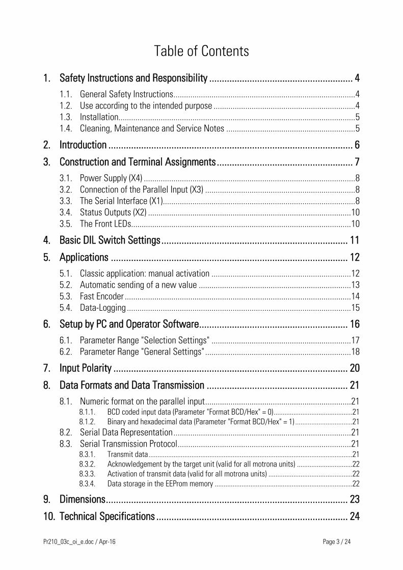
Table of Contents
1. Safety Instructions and Responsibility ......................................................... 4
1.1. General Safety Instructions ...................................................................................... 4
1.2. Use according to the intended purpose ................................................................... 4
1.3. Installation................................................................................................................ 5
1.4. Cleaning, Maintenance and Service Notes ............................................................. 5
2. Introduction ................................................................................................. 6
3. Construction and Terminal Assignments ...................................................... 7
3.1. Power Supply (X4) .................................................................................................... 8
3.2. Connection of the Parallel Input (X3) ....................................................................... 8
3.3. The Serial Interface (X1) ........................................................................................... 8
3.4. Status Outputs (X2) ................................................................................................ 10
3.5. The Front LEDs........................................................................................................ 10
4. Basic DIL Switch Settings .......................................................................... 11
5. Applications .............................................................................................. 12
5.1. Classic application: manual activation .................................................................. 12
5.2. Automatic sending of a new value ........................................................................ 13
5.3. Fast Encoder ........................................................................................................... 14
5.4. Data-Logging .......................................................................................................... 15
6. Setup by PC and Operator Software ........................................................... 16
6.1. Parameter Range "Selection Settings" .................................................................. 17
6.2. Parameter Range "General Settings" ..................................................................... 18
7. Input Polarity ............................................................................................. 20
8. Data Formats and Data Transmission ........................................................ 21
8.1. Numeric format on the parallel input ..................................................................... 21
8.1.1. BCD coded input data (Parameter "Format BCD/Hex" = 0) ............................................21
8.1.2. Binary and hexadecimal data (Parameter "Format BCD/Hex" = 1) ................................21
8.2. Serial Data Representation .................................................................................... 21
8.3. Serial Transmission Protocol .................................................................................. 21
8.3.1. Transmit data ..................................................................................................................21
8.3.2. Acknowledgement by the target unit (valid for all motrona units) ...............................22
8.3.3. Activation of transmit data (valid for all motrona units) ...............................................22
8.3.4. Data storage in the EEProm memory .............................................................................22
9. Dimensions ................................................................................................ 23
10. Technical Specifications ............................................................................ 24

Pr210_03c_oi_e.doc / Apr-16 Page 4 / 24
1. Safety Instructions and Responsibility
1.1. General Safety Instructions This operation manual is a significant component of the unit and includes important rules and
hints about the installation, function and usage. Non-observance can result in damage and/or
impairment of the functions to the unit or the machine or even in injury to persons using the
equipment!
Please read the following instructions carefully before operating the device and observe all
safety and warning instructions! Keep the manual for later use.
A pertinent qualification of the respective staff is a fundamental requirement in order to use
these manual. The unit must be installed, connected and put into operation by a qualified
electrician.
Liability exclusion: The manufacturer is not liable for personal injury and/or damage to property
and for consequential damage, due to incorrect handling, installation and operation. Further
claims, due to errors in the operation manual as well as misinterpretations are excluded from
liability.
In addition the manufacturer reserve the right to modify the hardware, software or operation
manual at any time and without prior notice. Therefore, there might be minor differences
between the unit and the descriptions in operation manual.
The raiser respectively positioner is exclusively responsible for the safety of the system and
equipment where the unit will be integrated.
During installation or maintenance all general and also all country- and application-specific
safety rules and standards must be observed.
If the device is used in processes, where a failure or faulty operation could damage the system
or injure persons, appropriate precautions to avoid such consequences must be taken.
1.2. Use according to the intended purpose The unit is intended exclusively for use in industrial machines, constructions and systems. Non-
conforming usage does not correspond to the provisions and lies within the sole responsibility
of the user. The manufacturer is not liable for damages which has arisen through unsuitable
and improper use. Please note that device may only be installed in proper form and used in a
technically perfect condition and in accordance to the Technical Specifications (see chapter 10).
The device is not suitable for operation in explosion-proof areas or areas which are excluded by
the EN 61010-1 standard.

Pr210_03c_oi_e.doc / Apr-16 Page 5 / 24
1.3. Installation The device is only allowed to be installed and operated within the permissible temperature
range. Please ensure an adequate ventilation and avoid all direct contact between the device
and hot or aggressive gases and liquids.
Before installation or maintenance, the unit must be disconnected from all voltage-sources.
Further it must be ensured that no danger can arise by touching the disconnected voltage-
sources.
Devices which are supplied by AC-voltages, must be connected exclusively by switches,
respectively circuit-breakers with the low voltage network. The switch or circuit-breaker must
be placed as near as possible to the device and further indicated as separator.
Incoming as well as outgoing wires and wires for extra low voltages (ELV) must be separated
from dangerous electrical cables (SELV circuits) by using a double resp. increased isolation.
All selected wires and isolations must be conform to the provided voltage- and temperature-
ranges. Further all country- and application-specific standards, which are relevant for structure,
form and quality of the wires, must be ensured. Indications about the permissible wire cross-
sections for wiring are described in the Technical Specifications (see chapter 10).
Before first start-up it must be ensured that all connections and wires are firmly seated and
secured in the screw terminals. All (inclusively unused) terminals must be fastened by turning
the relevant screws clockwise up to the stop.
Overvoltages at the connections must be limited to values in accordance to the overvoltage
category II.
For placement, wiring, environmental conditions as well as shielding and earthing/grounding of
the supply lines the general standards of industrial automation industry and the specific shielding
instructions of the manufacturer are valid. Please find all respective hints and rules on
„ www.motrona.com/download.html --> [General EMC Rules for Wiring, Screening and Earthing]”.
1.4. Cleaning, Maintenance and Service Notes To clean the front of the unit please use only a slightly damp (not wet!), soft cloth. For the rear
no cleaning is necessary. For an unscheduled, individual cleaning of the rear the maintenance
staff or assembler is self-responsible.
During normal operation no maintenance is necessary. In case of unexpected problems, failures
or malfunctions the device must be shipped for back to the manufacturer for checking,
adjustment and reparation (if necessary). Unauthorized opening and repairing can have
negative effects or failures to the protection-measures of the unit.

Pr210_03c_oi_e.doc / Apr-16 Page 6 / 24
2. Introduction The PR210 signal converter is used for conversion of parallel data from encoders, sensors,
thumbwheel switches or PLC into serial information. One of the major applications refers to
replacement of obsolete control products using parallel data interface against new products
providing serial interface only. With use of the PR210 converter the customer can keep all the
parallel structure and cabling of an existing machine and still use modern controllers with serial
interface. Besides this typical application the converter can also be used for many other
technical solutions.
The PR210 parallel input accepts data with BCD, binary or Gray code.
The input data will be packed into a serial protocol and transmitted to one or several target
units via RS232 / RS485 interface.
Conversion and transmission can be controlled at any time by means of the digital status
output signals.
As required four totally difference field of application can be used.
1. Classic application: manual activation
2. Automatic importing and forwarding of new values
3. Fast encoder
4. Data logging
For more detailed information to these four cases see chapter 5.

Pr210_03c_oi_e.doc / Apr-16 Page 7 / 24
3. Construction and Terminal Assignments
LEDs
GN
D
21
GND
X2X1
X3
Sub-D-9 female
Sub-D-25 (male)
X4+24 VDC
Co
m+
Scre
en X
1
Green LED: ONYellow LED: BUSY
Scre
en
X3
DIL
Sw
itch
RS232 / RS485
Status Outputs
Parallel Input
Power Supply
GN
D Inpu
t E
rror
Bu
sy
No r
esp
on
se
Com
m.
Err
.
Pr210_03c_oi_e.doc / Apr-16 Page 8 / 24
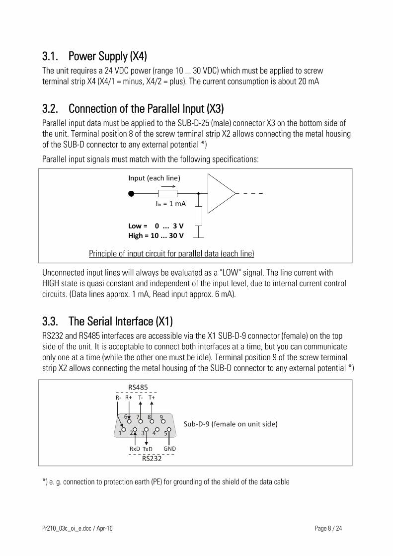
3.1. Power Supply (X4) The unit requires a 24 VDC power (range 10 ... 30 VDC) which must be applied to screw
terminal strip X4 (X4/1 = minus, X4/2 = plus). The current consumption is about 20 mA
3.2. Connection of the Parallel Input (X3) Parallel input data must be applied to the SUB-D-25 (male) connector X3 on the bottom side of
the unit. Terminal position 8 of the screw terminal strip X2 allows connecting the metal housing
of the SUB-D connector to any external potential *)
Parallel input signals must match with the following specifications:
Input (each line)
Low = 0 ... 3 VHigh = 10 ... 30 V
I = 1 mAin
Principle of input circuit for parallel data (each line)
Unconnected input lines will always be evaluated as a "LOW" signal. The line current with
HIGH state is quasi constant and independent of the input level, due to internal current control
circuits. (Data lines approx. 1 mA, Read input approx. 6 mA).
3.3. The Serial Interface (X1) RS232 and RS485 interfaces are accessible via the X1 SUB-D-9 connector (female) on the top
side of the unit. It is acceptable to connect both interfaces at a time, but you can communicate
only one at a time (while the other one must be idle). Terminal position 9 of the screw terminal
strip X2 allows connecting the metal housing of the SUB-D connector to any external potential *)
54321
9876
GNDTxDRxD
RS232
T+T-R+R-
RS485
Sub-D-9 (female on unit side)
*) e. g. connection to protection earth (PE) for grounding of the shield of the data cable
Pr210_03c_oi_e.doc / Apr-16 Page 9 / 24
54
32
1
98
76
53
2
54
32
1
98
76
53
2
GND
TxDRxD
PR210 PC or target unit
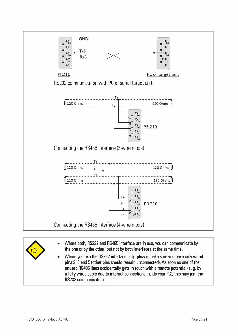
RS232 communication with PC or serial target unit
54
32
1
98
76
54
32
1
98
76
T+
T-120 Ohms 120 Ohms
PR 210
Connecting the RS485 interface (2-wire mode)
54
32
1
98
76
54
32
1
98
76
T+
T-
120 Ohms 120 Ohms
PR 210
120 Ohms 120 Ohms
R+
R-
T+
T-
R+
R-
Connecting the RS485 interface (4-wire mode)
Where both, RS232 and RS485 interface are in use, you can communicate by
the one or by the other, but not by both interfaces at the same time.
Where you use the RS232 interface only, please make sure you have only wired
pins 2, 3 and 5 (other pins should remain unconnected). As soon as one of the
unused RS485 lines accidentally gets in touch with a remote potential (e. g. by
a fully wired cable due to internal connections inside your PC), this may jam the
RS232 communication.
Pr210_03c_oi_e.doc / Apr-16 Page 10 / 24
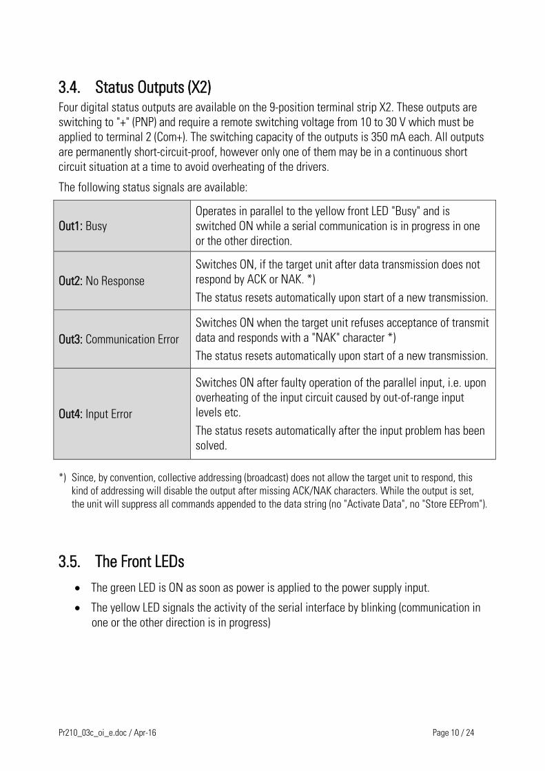
3.4. Status Outputs (X2) Four digital status outputs are available on the 9-position terminal strip X2. These outputs are
switching to "+" (PNP) and require a remote switching voltage from 10 to 30 V which must be
applied to terminal 2 (Com+). The switching capacity of the outputs is 350 mA each. All outputs
are permanently short-circuit-proof, however only one of them may be in a continuous short
circuit situation at a time to avoid overheating of the drivers.
The following status signals are available:
Out1: Busy
Operates in parallel to the yellow front LED "Busy" and is
switched ON while a serial communication is in progress in one
or the other direction.
Out2: No Response
Switches ON, if the target unit after data transmission does not
respond by ACK or NAK. *)
The status resets automatically upon start of a new transmission.
Out3: Communication Error
Switches ON when the target unit refuses acceptance of transmit
data and responds with a "NAK" character *)
The status resets automatically upon start of a new transmission.
Out4: Input Error
Switches ON after faulty operation of the parallel input, i.e. upon
overheating of the input circuit caused by out-of-range input
levels etc.
The status resets automatically after the input problem has been
solved.
*) Since, by convention, collective addressing (broadcast) does not allow the target unit to respond, this
kind of addressing will disable the output after missing ACK/NAK characters. While the output is set,
the unit will suppress all commands appended to the data string (no "Activate Data", no "Store EEProm").
3.5. The Front LEDs
The green LED is ON as soon as power is applied to the power supply input.
The yellow LED signals the activity of the serial interface by blinking (communication in
one or the other direction is in progress)
Pr210_03c_oi_e.doc / Apr-16 Page 11 / 24
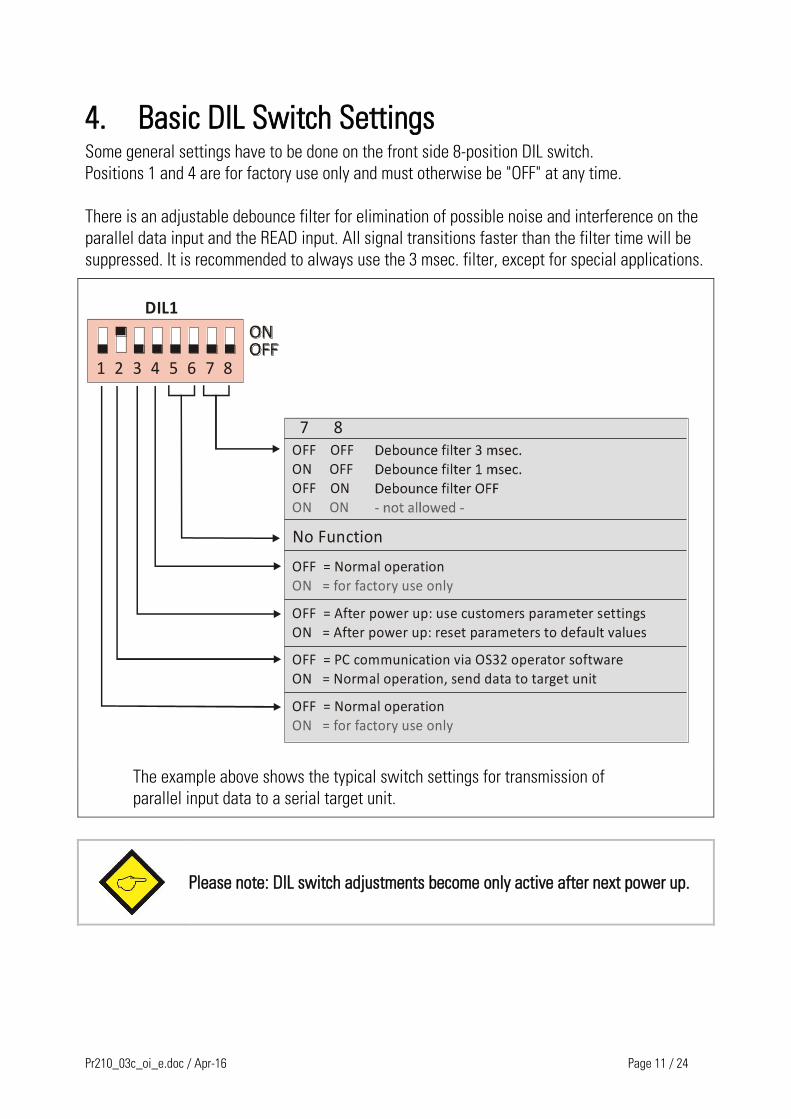
4. Basic DIL Switch Settings Some general settings have to be done on the front side 8-position DIL switch.
Positions 1 and 4 are for factory use only and must otherwise be "OFF" at any time.
There is an adjustable debounce filter for elimination of possible noise and interference on the
parallel data input and the READ input. All signal transitions faster than the filter time will be
suppressed. It is recommended to always use the 3 msec. filter, except for special applications.
1 2 3 4 5 6 7 8
DIL1
7 8OFF OFFON OFFOFF ONON ON
No Function
OFF = Normal operationON = for factory use only
OFF = After power up: use customers parameter settingsON = After power up: reset parameters to default values
OFF = PC communication via OS32 operator softwareON = Normal operation, send data to target unit
OFF = Normal operationON = for factory use only
The example above shows the typical switch settings for transmission of
parallel input data to a serial target unit.
Please note: DIL switch adjustments become only active after next power up.

Pr210_03c_oi_e.doc / Apr-16 Page 12 / 24
5. Applications Depending on the setting of the parameters „Parallel Reading Timer“ and „Serial Timer“ four
different cases are possible.
For the description of the complete protocol for the serial communication see chapter 8.3.
5.1. Classic application: manual activation A typical example is shown in the below-mentioned illustration.
+
-
+
-
+
-
+
-
+
-BCD thumbwheel switch
PR 210
1 2 3 4+
Parameter preset
Read
RS232R
S 48
5-B
us
More target units
Control Unit
Speed-variable drive
Remote setting of operational parameters via simple BCD thumbwheel switch set
An operator parameter for a controller and/or a drive should be set via an external BCD
thumbwheel switch. The selection of the operating parameter and the selection of the target
unit take place through the three connectors of the target selection.
With the activation of the Read-Pin the parallel input will be imported once.
The imported value will be forwarded via the serial device automatically.
Stable signal conditions must be guaranteed at the connectors of the parallel
input pins. Otherwise a safe selection of the operating parameter (or the
selection of the target unit) cannot be assured.
Overview of the relevant parameters and the READ-Pins:
Parameter Approaching/using
„Parallel Reading Timer“ = 0
„Serial Timer“ = 0
READ-Pin ACTIVE: is using
Pr210_03c_oi_e.doc / Apr-16 Page 13 / 24
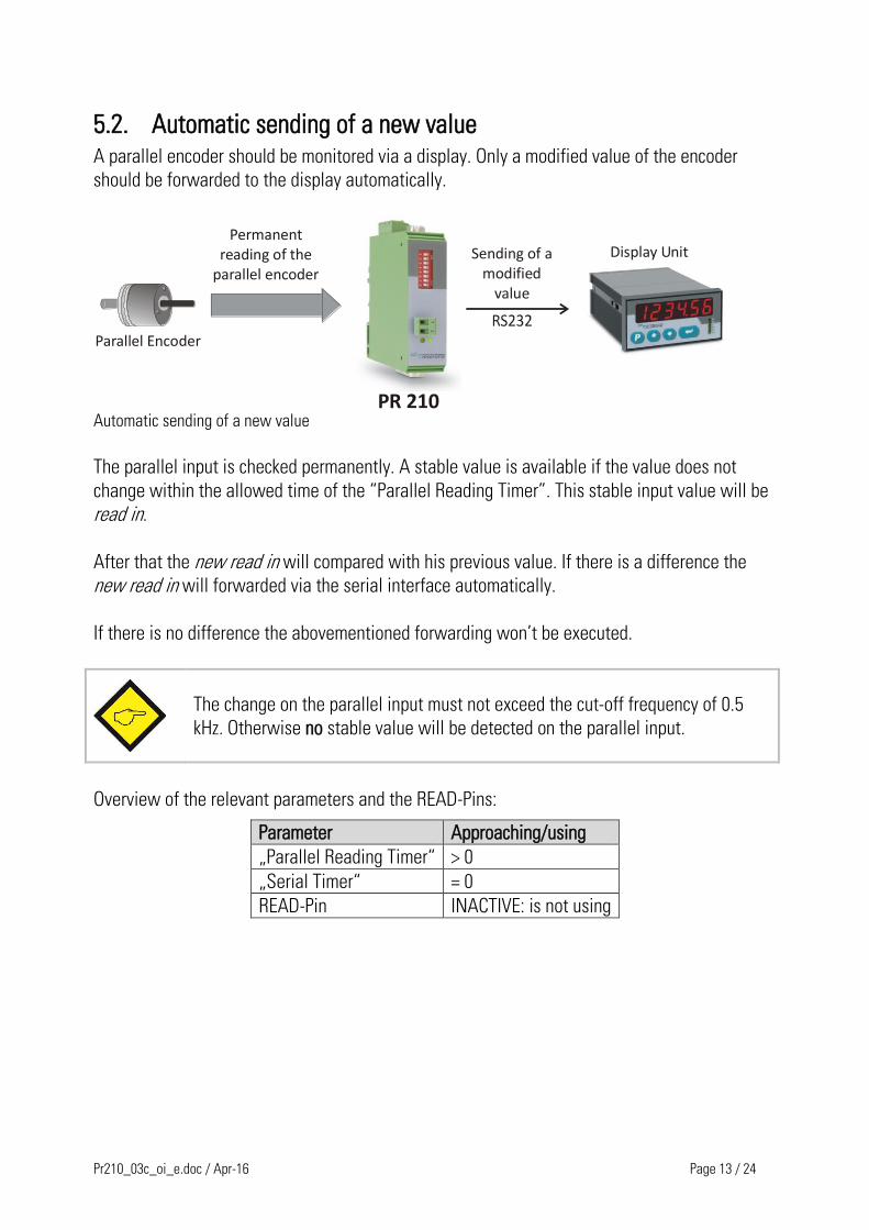
5.2. Automatic sending of a new value A parallel encoder should be monitored via a display. Only a modified value of the encoder
should be forwarded to the display automatically.
PR 210
Display UnitPermanent
reading of the parallel encoder
Parallel Encoder
Sending of a modified
value
Automatic sending of a new value
The parallel input is checked permanently. A stable value is available if the value does not
change within the allowed time of the “Parallel Reading Timer”. This stable input value will be
read in.
After that the new read in will compared with his previous value. If there is a difference the
new read in will forwarded via the serial interface automatically.
If there is no difference the abovementioned forwarding won’t be executed.
The change on the parallel input must not exceed the cut-off frequency of 0.5
kHz. Otherwise no stable value will be detected on the parallel input.
Overview of the relevant parameters and the READ-Pins:
Parameter Approaching/using
„Parallel Reading Timer“ > 0
„Serial Timer“ = 0
READ-Pin INACTIVE: is not using
Pr210_03c_oi_e.doc / Apr-16 Page 14 / 24
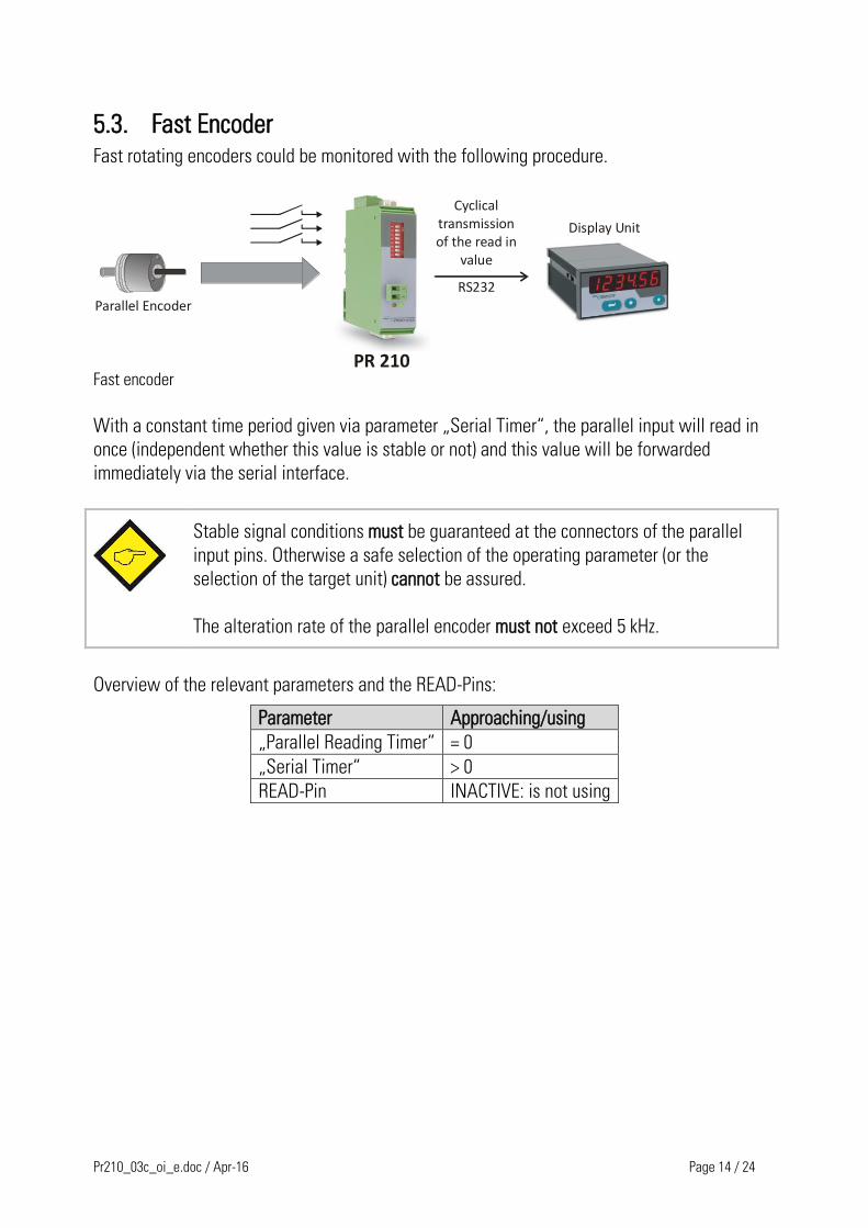
5.3. Fast Encoder Fast rotating encoders could be monitored with the following procedure.
PR 210
RS232
Display Unit
Parallel Encoder
Cyclical transmission of the read in
value
Fast encoder
With a constant time period given via parameter „Serial Timer“, the parallel input will read in
once (independent whether this value is stable or not) and this value will be forwarded
immediately via the serial interface.
Stable signal conditions must be guaranteed at the connectors of the parallel
input pins. Otherwise a safe selection of the operating parameter (or the
selection of the target unit) cannot be assured.
The alteration rate of the parallel encoder must not exceed 5 kHz.
Overview of the relevant parameters and the READ-Pins:
Parameter Approaching/using
„Parallel Reading Timer“ = 0
„Serial Timer“ > 0
READ-Pin INACTIVE: is not using
Pr210_03c_oi_e.doc / Apr-16 Page 15 / 24
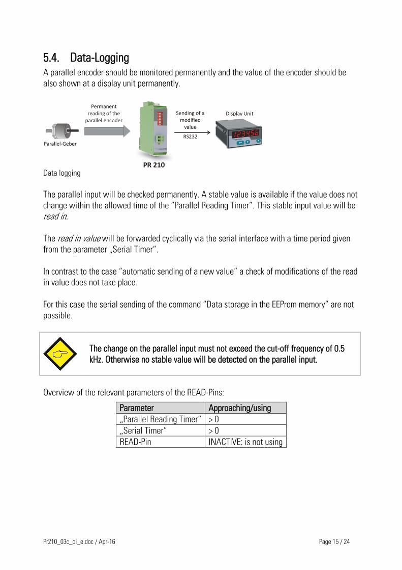
5.4. Data-Logging A parallel encoder should be monitored permanently and the value of the encoder should be
also shown at a display unit permanently.
PR 210
RS232
Permanent reading of the
parallel encoder
Parallel-Geber
Sending of a modified
value
Data logging
The parallel input will be checked permanently. A stable value is available if the value does not
change within the allowed time of the “Parallel Reading Timer”. This stable input value will be
read in.
The read in value will be forwarded cyclically via the serial interface with a time period given
from the parameter „Serial Timer“.
In contrast to the case “automatic sending of a new value” a check of modifications of the read
in value does not take place.
For this case the serial sending of the command “Data storage in the EEProm memory” are not
possible.
The change on the parallel input must not exceed the cut-off frequency of 0.5
kHz. Otherwise no stable value will be detected on the parallel input.
Overview of the relevant parameters of the READ-Pins:
Parameter Approaching/using
„Parallel Reading Timer“ > 0
„Serial Timer“ > 0
READ-Pin INACTIVE: is not using
Pr210_03c_oi_e.doc / Apr-16 Page 16 / 24
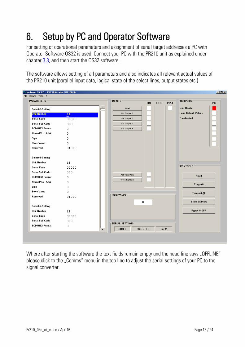
6. Setup by PC and Operator Software For setting of operational parameters and assignment of serial target addresses a PC with
Operator Software OS32 is used. Connect your PC with the PR210 unit as explained under
chapter 3.3, and then start the OS32 software.
The software allows setting of all parameters and also indicates all relevant actual values of
the PR210 unit (parallel input data, logical state of the select lines, output states etc.)
Where after starting the software the text fields remain empty and the head line says „OFFLINE“
please click to the „Comms“ menu in the top line to adjust the serial settings of your PC to the
signal converter.

Pr210_03c_oi_e.doc / Apr-16 Page 17 / 24
6.1. Parameter Range "Selection Settings" The selection lines Sel.0 - Sel.2 of the parallel input connector allow selection of totally
8 different target addresses or destination codes for serial transmit data
(Select0 to Select7). For any of these 8 destinations the parameters shown below can be set
individually.
Sel.2 Sel.1 Sel.0 Target specification according to parameter setting
0 0 0 Select-0
0 0 1 Select-1
0 1 0 Select-2
0 1 1 Select-3
1 0 0 Select-4
1 0 1 Select-5
1 1 0 Select-6
1 1 1 Select-7
Parameter (Select 0 - 7) Range Default
Unit Nr.
Serial device address of the target unit.
Addresses containing a "0" are reserved for collective addressing.
Setting "00" will address all units (broadcast address).
Setting "10" will address all units from 11 to 19 etc.
00 - 99 11
Serial Code
Serial code of the register location inside the addressed unit
(decimal representation)
Example: to address the register code "A0" (hexadecimal) this parameter
must be set to "160" (decimal)
0 - 65535 0000 - FFFF
(hex)
Serial Sub Code (only applicable with units using extended addressing)
Serial Sub Code, sub division of the Serial Code.
Must be set to 0 with all units using standard addressing (e.g. BY340)
0 - 255 00 - FF
(hex)
Format BCD / Hex
Code of data used on the parallel input
0 = data use BCD 1-2-4-8 code
1 = data use binary or hexadecimal code
2 = data use Gray code
0 - 2
Normal / Extend Addr.
Protocol selection (standard or extended protocol)
0 = Standard protocol (used for most units, e.g. BY340)
1 = Extended Protocol (used for MC700 controllers and many drives)
0, 1
Pr210_03c_oi_e.doc / Apr-16 Page 18 / 24
Parameter (Select 0 - 7) Range Default
Sign (with BCD data only i.e. when parameter "Format BCD/Hex" = 0)
Signed or unsigned data
0 = data are without a sign
1 = most significant bit is a sign (MSD8 = Pin 13) (MSD8 = 0 means "+" and MSD8 = 1 means "-")
0, 1 0
Store Value
Parameter for automatic EEProm storage
0 = "Store EEProm" command will be added automatically
1 = no "Store EEProm" command will be added
(see clarification under 8.3.4)
0, 1 0
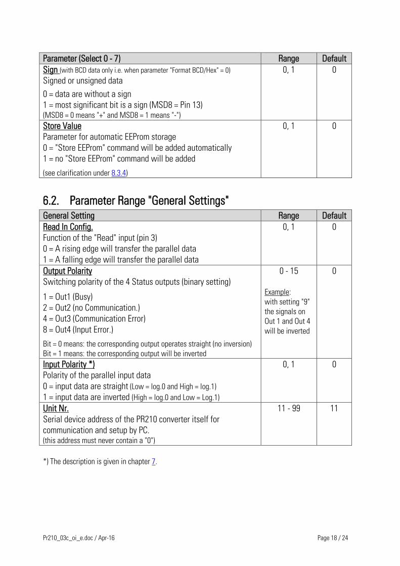
6.2. Parameter Range "General Settings"
General Setting Range Default
Read In Config.
Function of the "Read" input (pin 3)
0 = A rising edge will transfer the parallel data
1 = A falling edge will transfer the parallel data
0, 1 0
Output Polarity
Switching polarity of the 4 Status outputs (binary setting)
1 = Out1 (Busy)
2 = Out2 (no Communication.)
4 = Out3 (Communication Error)
8 = Out4 (Input Error.)
Bit = 0 means: the corresponding output operates straight (no inversion)
Bit = 1 means: the corresponding output will be inverted
0 - 15
Example:
with setting "9"
the signals on
Out 1 and Out 4
will be inverted
0
Input Polarity *)
Polarity of the parallel input data
0 = input data are straight (Low = log.0 and High = log.1)
1 = input data are inverted (High = log.0 and Low = Log.1)
0, 1 0
Unit Nr.
Serial device address of the PR210 converter itself for
communication and setup by PC. (this address must never contain a "0")
11 - 99 11
*) The description is given in chapter 7.
Pr210_03c_oi_e.doc / Apr-16 Page 19 / 24
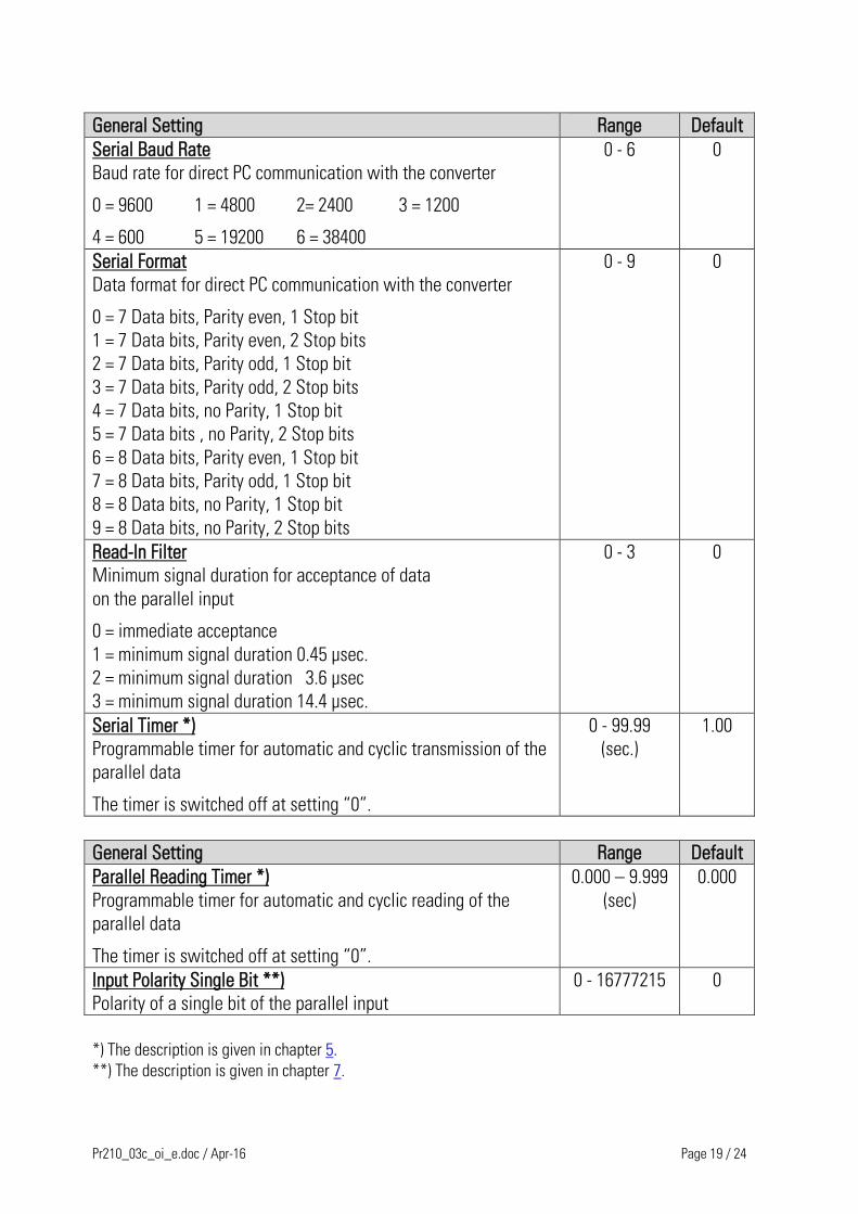
General Setting Range Default
Serial Baud Rate
Baud rate for direct PC communication with the converter
0 = 9600 1 = 4800 2= 2400 3 = 1200
4 = 600 5 = 19200 6 = 38400
0 - 6 0
Serial Format
Data format for direct PC communication with the converter
0 = 7 Data bits, Parity even, 1 Stop bit
1 = 7 Data bits, Parity even, 2 Stop bits
2 = 7 Data bits, Parity odd, 1 Stop bit
3 = 7 Data bits, Parity odd, 2 Stop bits
4 = 7 Data bits, no Parity, 1 Stop bit
5 = 7 Data bits , no Parity, 2 Stop bits
6 = 8 Data bits, Parity even, 1 Stop bit
7 = 8 Data bits, Parity odd, 1 Stop bit
8 = 8 Data bits, no Parity, 1 Stop bit
9 = 8 Data bits, no Parity, 2 Stop bits
0 - 9 0
Read-In Filter
Minimum signal duration for acceptance of data
on the parallel input
0 = immediate acceptance
1 = minimum signal duration 0.45 µsec.
2 = minimum signal duration 3.6 µsec
3 = minimum signal duration 14.4 µsec.
0 - 3 0
Serial Timer *)
Programmable timer for automatic and cyclic transmission of the
parallel data
The timer is switched off at setting “0”.
0 - 99.99
(sec.)
1.00
General Setting Range Default
Parallel Reading Timer *)
Programmable timer for automatic and cyclic reading of the
parallel data
The timer is switched off at setting “0”.
0.000 – 9.999
(sec)
0.000
Input Polarity Single Bit **)
Polarity of a single bit of the parallel input
0 - 16777215 0
*) The description is given in chapter 5.
**) The description is given in chapter 7.
Pr210_03c_oi_e.doc / Apr-16 Page 20 / 24
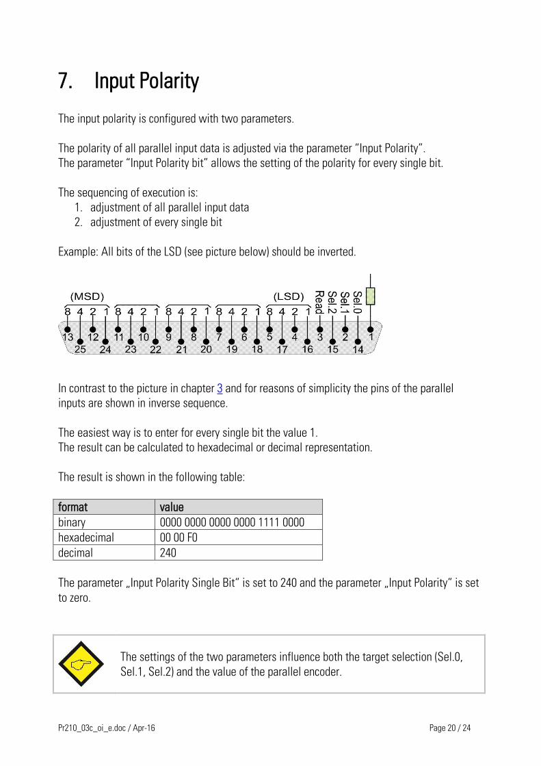
7. Input Polarity
The input polarity is configured with two parameters.
The polarity of all parallel input data is adjusted via the parameter “Input Polarity”.
The parameter “Input Polarity bit” allows the setting of the polarity for every single bit.
The sequencing of execution is:
1. adjustment of all parallel input data
2. adjustment of every single bit
Example: All bits of the LSD (see picture below) should be inverted.
In contrast to the picture in chapter 3 and for reasons of simplicity the pins of the parallel
inputs are shown in inverse sequence.
The easiest way is to enter for every single bit the value 1.
The result can be calculated to hexadecimal or decimal representation.
The result is shown in the following table:
format value
binary 0000 0000 0000 0000 1111 0000
hexadecimal 00 00 F0
decimal 240
The parameter „Input Polarity Single Bit“ is set to 240 and the parameter „Input Polarity“ is set
to zero.
The settings of the two parameters influence both the target selection (Sel.0,
Sel.1, Sel.2) and the value of the parallel encoder.

Pr210_03c_oi_e.doc / Apr-16 Page 21 / 24
8. Data Formats and Data Transmission
8.1. Numeric format on the parallel input
8.1.1. BCD coded input data (Parameter "Format BCD/Hex" = 0)
The following numeric range will be evaluated:
Unsigned data (Parameter "Sign" = 0):
The numeric range is defined from 0 to 99 999
Signed data (Parameter "Sign" = 1)
The numeric range is defined from -79 999 to + 79 999
8.1.2. Binary and hexadecimal data (Parameter "Format BCD/Hex" = 1)
Only the lower 16 bits will be evaluated (pin 16 = least significant bit, pin 11 = most significant bit)
Binary data will be considered as unsigned at any time.
8.2. Serial Data Representation
On the serial site numbers will always be expressed in ASCII format.
Leading zeros will never be transmitted
Positive signs will not be transmitted.
Example with BCD data: when the parallel input reads the BCD data 15724, the ASCII result in
the data field of the serial string will appear as 31 35 37 32 34 (hex)
Example with binary or hex data: when the parallel input reads the binary data
0001 0011 1001 1100 (hex 139C), this is equal to a decimal value of 5020. Accordingly the
ASCII result in the data field of the serial string will appear as 35 30 32 30 (hex)
8.3. Serial Transmission Protocol Subsequent indications use standard addressing. *)
8.3.1. Transmit data
After triggering the "Read" command (remotely or by serial timer) the PR210 converter will
transmit the data according to the following protocol:
EOT AD1 AD2 STX C1 C2 x x x x x x x ETX BCC
EOT = Control character (Hex 04)
AD1 = Device address of target unit, High Byte
AD2 = Device address of target unit, Low Byte
STX = Control character (Hex 02)
C1 = register code of destination, High Byte
C2 = register code of destination, Low Byte
xxxxx = numeric data field (numbers use ASCII format)
ETX = Control character (Hex 03)
BCC = Block check character
*) For details about extended addressing please refer to the special document "SERPRO"

Pr210_03c_oi_e.doc / Apr-16 Page 22 / 24
No leading zeros will be transmitted.
The Block-Check-Character (BCC) is generated by the EXCLUSIV-OR function of all
characters from C1 thru ETX
Positive values always appear without a sign. Only negative BCD values appear with
a negative sign on top (ASCII "-" corresponding to 2D (hex) )
8.3.2. Acknowledgement by the target unit (valid for all motrona units)
When the target unit has received the data string correctly, the response will be "ACK"
(Acknowledge, control character 06 hex.) Where an error has been detected during transmission,
the response will be "NAK" (Negative acknowledge, control character 15 hex )
8.3.3. Activation of transmit data (valid for all motrona units)
After the target unit has received and stored new data, they have still to be activated by means
of the special command "Activate Data". Hence, after the target unit has sent back a positive
acknowledge "ACK" to the PR210 converter, the converter must send the "Activate" command
after. This command consists of the data value "1" sent to the register code "67". In an example
with a serial device address of "11" the full activation string is:
ASCII EOT 1 1 STX 6 7 1 ETX BCC
Hex 0 4 3 1 3 1 0 2 3 6 3 7 3 1 0 3 3 3
Address Activation Data
8.3.4. Data storage in the EEProm memory
With all motrona units the data is first transferred to the random access memory (RAM). This
means the data are available and active until to the next power down only. After next power up
the previous data stored in the EEProm will be reloaded.
If the data sent by the PR210 should be stored permanently in the non-volatile EEProm memory,
this may be achieved by setting parameter "Store Value" correspondingly. When set to "0", the
data string and the activation string will be automatically followed by a Store command. This
command consists of the data value "1" sent to the register code "68". In an example with a
serial device address of "11" the full string for EEProm storage is:
ASCII EOT 1 1 STX 6 7 1 ETX BCC
Hex 0 4 3 1 3 1 0 2 3 6 3 8 3 1 0 3 3 0
Address Store Data

Pr210_03c_oi_e.doc / Apr-16 Page 23 / 24
9. Dimensions
102 (4.016”)
91 (3.583”)
82.5
(3.2
48
”)
10
2 (
4.0
16
”)22.5
(0.886”)
Side View
Top View
Front View
Pr210_03c_oi_e.doc / Apr-16 Page 24 / 24
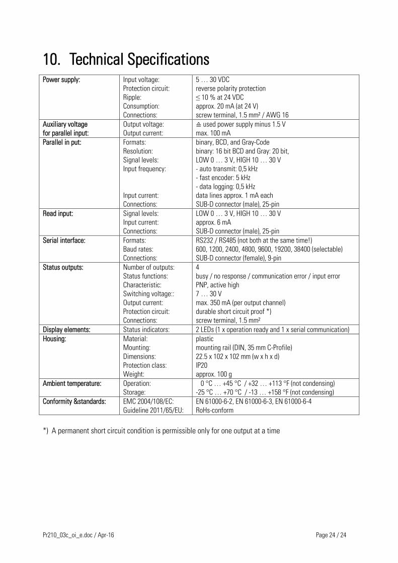
10. Technical Specifications
Power supply: Input voltage:
Protection circuit:
Ripple:
Consumption:
Connections:
5 … 30 VDC
reverse polarity protection
≤ 10 % at 24 VDC
approx. 20 mA (at 24 V)
screw terminal, 1.5 mm² / AWG 16
Auxiliary voltage
for parallel input:
Output voltage:
Output current:
≙ used power supply minus 1.5 V
max. 100 mA
Parallel in put: Formats:
Resolution:
Signal levels:
Input frequency:
Input current:
Connections:
binary, BCD, and Gray-Code
binary: 16 bit BCD and Gray: 20 bit,
LOW 0 … 3 V, HIGH 10 … 30 V
- auto transmit: 0,5 kHz
- fast encoder: 5 kHz
- data logging: 0,5 kHz
data lines approx. 1 mA each
SUB-D connector (male), 25-pin
Read input: Signal levels:
Input current:
Connections:
LOW 0 … 3 V, HIGH 10 … 30 V
approx. 6 mA
SUB-D connector (male), 25-pin
Serial interface: Formats:
Baud rates:
Connections:
RS232 / RS485 (not both at the same time!)
600, 1200, 2400, 4800, 9600, 19200, 38400 (selectable)
SUB-D connector (female), 9-pin
Status outputs: Number of outputs:
Status functions:
Characteristic:
Switching voltage::
Output current:
Protection circuit:
Connections:
4
busy / no response / communication error / input error
PNP, active high
7 … 30 V
max. 350 mA (per output channel)
durable short circuit proof *)
screw terminal, 1.5 mm²
Display elements: Status indicators: 2 LEDs (1 x operation ready and 1 x serial communication)
Housing: Material:
Mounting:
Dimensions:
Protection class:
Weight:
plastic
mounting rail (DIN, 35 mm C-Profile)
22.5 x 102 x 102 mm (w x h x d)
IP20
approx. 100 g
Ambient temperature: Operation:
Storage:
0 °C … +45 °C / +32 … +113 °F (not condensing)
-25 °C … +70 °C / -13 … +158 °F (not condensing)
Conformity &standards: EMC 2004/108/EC:
Guideline 2011/65/EU:
EN 61000-6-2, EN 61000-6-3, EN 61000-6-4
RoHs-conform
*) A permanent short circuit condition is permissible only for one output at a time

![BCD & Accessories 2010 - nemo-sub.comEN][PreVer].pdf · Page BC4| BCD & Accessories BCD & Accessories| Page 5 The BC-87 Elite Pro from AQUATEC™ is an internal bladderless BCD that](https://img.pdfslide.net/doc/110x75/5ea4f75f48423e5c5a379918/bcd-accessories-2010-nemo-sub-enpreverpdf-page-bc4-bcd-accessories.jpg)