Embed Size (px)
Citation preview

Operatin
g M
anual
Axio
Im
ager
Uprig
ht M
icroscope
Carl Zeiss Copyright / Trademarks Axio Imager
2 B 46-0046 e 12/05
Knowledge of this manual is required for the operation of the instrument. Would you therefore please make yourself familiar with the contents of this manual and pay special attention to hints concerning safe operation of the instrument.
The specifications are subject to change; the manual is not covered by an update service.
© Unless expressly authorized, forwarding and duplication of this document and the software package, as well as utilization and communication of its contents are not permitted. Violations will entail an obligation to pay compensation.
All rights reserved in the event of granting of patents or registration of a utility model.
All names of companies and products mentioned in this manual may be trademarks or registered trademarks. Quoting of product names is for information only and does not represent any trademark misuse.
Carl Zeiss AG is not liable for the performance or the use of these products.
Issued by: Carl Zeiss AG Light Microscopy P.O.B. 4041 37030 Göttingen GERMANY Phone: ++49 551 5060 660 Telefax: ++49 551 5060 464 Internet: www.zeiss.de/micro E-Mail: [email protected]
Number of this Operating Manual: B 46-0078 e
Date of issue: Version 1 - 12/20/2005
Axio Imager Contents Carl Zeiss
B 46-0046 e 12/05 3
CONTENTS
Page
1 Introduction........................................................................................................................6 1.1 Notes on instrument safety ...................................................................................................6 1.2 Notes on warranty ................................................................................................................9 1.3 Overall view of Axio Imager – manual .................................................................................10 1.4 Overall view of Axio Imager - motorized..............................................................................11
2 Instrument Decription......................................................................................................12 2.1 Name and intended use ......................................................................................................12 2.2 Instrument description and main features............................................................................12 2.3 Equipment and compatibility table ......................................................................................13 2.4 System overview of Axio Imager..........................................................................................15 2.5 Objectives ...........................................................................................................................23 2.6 Eyepieces ............................................................................................................................24 2.7 Stage micrometers and eyepiece reticles..............................................................................24 2.8 Technical data.....................................................................................................................26
3 Start-up .............................................................................................................................29 3.1 Unpacking and installing the microscope.............................................................................29 3.2 Attaching or changing binocular tube or phototube............................................................30 3.3 Mounting the tube lens turret .............................................................................................31 3.4 Inserting eyepieces and auxiliary microscope........................................................................31 3.4.1 Inserting the eyepiece reticle ...............................................................................................32 3.4.2 Compensation of ametropia when eyepiece reticles are used ..............................................32 3.4.3 Inserting the fold-over eyecups............................................................................................33 3.5 Setting the interpupillary distance on the binocular tube .....................................................33 3.6 Setting the viewing height ..................................................................................................33 3.7 Fitting components to the camera port of the binocular phototube.....................................34 3.8 Screwing in objectives .........................................................................................................35 3.9 Attaching or changing the condenser..................................................................................35 3.10 Replacing the DIC prism on the universal condenser ............................................................36 3.11 Inserting reflector turret, compensator mount 6x20 or 4-position modulator turret .............37 3.12 Changing the stage carrier ..................................................................................................37 3.13 Equipping 2-position filter wheels 2x, discrete .....................................................................38 3.13.1 Filter wheel, manual............................................................................................................38 3.13.2 Filter wheel, 2-position, motorized ......................................................................................39 3.14 Installing and removing P&C reflector modules....................................................................40 3.14.1 Installing a module..............................................................................................................40 3.14.2 Removing a module ............................................................................................................40 3.15 Changing the filter set in the reflector module FL P&C.........................................................40
Carl Zeiss Contents Axio Imager
4 B 46-0046 e 12/05
3.16 Changing the beam splitter in the reflector module FL P&C.................................................42 3.17 Mounting the TFT display to the motorized stand................................................................43 3.18 Installing the focus linear sensor..........................................................................................44 3.19 Assembling the multidiscussion equipment .........................................................................45 3.20 Connecting to power ..........................................................................................................47 3.20.1 Manual stand......................................................................................................................47 3.20.2 Motorized stand..................................................................................................................47 3.21 HAL 100 halogen illuminator...............................................................................................48 3.21.1 Attaching the HAL 100 halogen illuminator.........................................................................48 3.21.2 Adjusting the HAL 100 halogen illuminator .........................................................................49 3.21.3 Replacing the HAL 100 halogen lamp..................................................................................50 3.22 Installing the LED illuminator for transmitted light ...............................................................51 3.23 HBO 100 illuminator ...........................................................................................................53 3.23.1 Inserting the HBO 103 W/2 mercury vapor short-arc lamp ...................................................53 3.23.2 Attaching the HBO 100 illuminator .....................................................................................53 3.23.3 Aligning the HBO 100 illuminator........................................................................................54 3.24 Electrical connections on the rear side of the microscope ....................................................55 3.24.1 Manual stand......................................................................................................................55 3.24.2 Motorized stand..................................................................................................................55 3.25 Changing the mechanical stage ..........................................................................................56 3.25.1 Fixed mechanical stage 75x50 R ..........................................................................................56 3.25.2 Rotary mechanical stage 75x50/240° R................................................................................56 3.25.3 Adjusting the travel range on ergonomic drive ....................................................................57 3.25.4 Removing and attaching additional sleeves..........................................................................58 3.25.5 Adjusting the smoothness (torque) of the two drive knobs of the ergonomic drive ..............58 3.25.6 Changing the specimen holder............................................................................................59 3.26 Rotary stage Pol ..................................................................................................................59 3.26.1 Removing rotary stage Pol...................................................................................................59 3.26.2 Attaching rotary stage Pol ...................................................................................................59 3.26.3 Centering rotary stage Pol...................................................................................................60 3.26.4 Centering objectives............................................................................................................61 3.27 Installing Polarizer D, fixed ..................................................................................................62
4 Operation..........................................................................................................................63 4.1 Axio Imager operation and function controls (manual version).............................................63 4.2 Axio Imager operation and function controls (motorized version) ........................................70 4.3 Switching microscope and HAL 100 illuminator on/off ........................................................74 4.4 Switching the HBO 100 on/off ............................................................................................75 4.5 Binocular phototube 30°/25 mot with two camera ports (2TV tube mot).............................75 4.6 Mechanical Stage 75x50 mot. CAN.....................................................................................77 4.6.1 Assembling Mechanical Stage 75x50 mot. CAN ..................................................................77 4.6.2 Connecting Mechanical Stage 75x50 mot. CAN ..................................................................78 4.6.3 Connecting Mechanical Stage 75x50 mot. CAN (Version 2 and mot. standard) ..................79 4.6.4 CAN/USB converter .............................................................................................................79
Axio Imager Contents Carl Zeiss
B 46-0046 e 12/05 5
4.7 Functions of the Light Manager...........................................................................................80 4.7.1 Light Manager Mode: OFF:..................................................................................................81 4.7.2 Light Manager Mode: CLASSIC ...........................................................................................81 4.7.3 Light Manager Mode: SMART .............................................................................................82 4.7.4 Light Manager of manual microscope .................................................................................83 4.7.5 Light Manager and Dazzle Protection control on manual stands ..........................................83 4.7.6 Light Manager of motorized microscope .............................................................................84 4.8 Operating the motorized microscope via touchscreen of TFT display ....................................85 4.8.1 Screen layout ......................................................................................................................85 4.8.2 Menu structure ...................................................................................................................87 4.8.3 Home page .........................................................................................................................88 4.8.4 Microscope page.................................................................................................................89 4.8.5 Settings.............................................................................................................................100 4.8.6 Display ..............................................................................................................................110 4.9 Illumination and contrast methods ....................................................................................111 4.9.1 Setting transmitted-light brightfield according to KÖHLER .................................................111 4.9.2 Setting transmitted-light darkfield .....................................................................................114 4.9.3 Setting transmitted-light phase contrast ............................................................................117 4.9.4 Setting transmitted-light differential interference contrast (DIC).........................................119 4.9.5 Setting transmitted-light polarization for orthoscopic observation......................................121 4.9.6 Setting transmitted-light polarization for conoscopic observation – determining the
optical character of crystals ...............................................................................................129 4.9.7 Setting reflected-light brightfield.......................................................................................132 4.9.8 Setting reflected-light darkfield .........................................................................................135 4.9.9 Setting reflected-light DIC and reflected-light C-DIC..........................................................136 4.9.10 Setting reflected-light TIC..................................................................................................138 4.9.11 Setting epi-fluorescence ....................................................................................................141 4.9.12 Setting reflected-light polarization – Detection of bireflection and reflection pleochroism ..143
5 Care, Maintenance, Troubleshooting and SERVICE .....................................................145 5.1 Instrument care.................................................................................................................145 5.2 Instrument maintenance ...................................................................................................146 5.2.1 Performing checks.............................................................................................................146 5.2.2 Changing fuses .................................................................................................................146 5.3 Troubleshooting................................................................................................................147 5.4 Spares, consumables and tools..........................................................................................150 5.5 Requesting service.............................................................................................................151
6 Appendix ........................................................................................................................152 6.1 List of abbreviations ..........................................................................................................152 6.2 Index.................................................................................................................................154 6.3 Industrial property rights ...................................................................................................158
INTRODUCTION Carl Zeiss Notes on instrument safety Axio Imager
6 B 46-0046 e 12/05
1 INTRODUCTION
1.1 Notes on instrument safety
The Axio Imager microscopes have been designed, produced and tested in compliance with DIN EN 61010-1 (IEC 61010-1) and IEC 61010-2-101 safety requirements for electrical measuring, control and laboratory instruments.
The instruments meet the requirements of EC Directive IVDD 98/79/EC (In Vitro Diagnostic); they are marked with the mark.
This operating manual includes information and warnings that must be observed by the user.
The following warning and information symbols are used in this manual:
NOTE This symbol is a warning, which you must observe under all circumstances.
CAUTION This symbol is a warning, which indicates a hazard to the instrument or instrument system.
CAUTION This symbol is a warning, which indicates a hazard to the user of the instrument.
CAUTION Hot surface!
CAUTION UV radiation is emitted!
CAUTION Laser radiation is emitted!
CAUTION Disconnect the instrument from line power before opening it!
INTRODUCTION Axio Imager Notes on instrument safety Carl Zeiss
B 46-0046 e 12/05 7
The Axio Imager microscopes, including original accessories, may only be used for the microscope techniques described in this manual.
Particular attention must be paid to the following warnings:
The manufacturer cannot assume any liability for any other applications of the instrument including those of individual modules or single parts. This also applies to all service or repair work that is not carried out by authorized service personnel. In case of non-compliance, all warranty claims shall be forfeited.
The power plug must be inserted in an outlet featuring a grounding (earth) contact. The grounding effect must not be made ineffective by an extension cable that does not have a protective ground wire.
If it is determined that protection measures are no longer effective, the instrument must be switched off and safeguarded against inadvertent operation. Please contact a Zeiss service agency or the Carl Zeiss Microscopy Service to repair the instrument.
On stands with motorized focusing drive, there is the risk of getting one's fingers jammed between stage carrier and the base of the stand, when the stage is moved down. Therefore, do not reach with your hands under the stage carrier.
The manual microscopes (Axio Imager.A1, .A1LED, .A1m, .D1 and .D1m) are equipped with a power supply integrated in the stand allowing line voltages to be used in the ranges 100 to 127 V and 200 to 240 V AC ±10 %, 50/60 Hz, without the voltage setting on the instrument having to be changed. The motorized models (Axio Imager.M1, .M1m, .Z1 and .Z1m) are powered through the separate power supply 230 belonging to the stand. On this power supply, too, the voltage setting need not be changed in the line voltage range 100 to 127 V and 200 to 240 V ±10 %, 50/60 Hz. The HBO 100 (ebq 100 dc) and XBO 75 (ebx 75 isolated) power supply units are designed for a line voltage range from 100 to 240 V AC, 50/60 Hz, and automatically adapt to the applied line voltage.
Before switching on the instrument, check whether it is suitable for the available line voltage. Always disconnect the instrument from the power outlet before opening the instrument and before changing the fuses. See section 5.2.2. Take care to ensure you only use fuses according to the information given in the Technical Data. Use of makeshift fuses and short-circuiting of the fuse holders are not permitted.
The Axio Imager microscopes are not equipped with any special devices for protection from substances that are corrosive, potentially infectious, toxic, radioactive, or other substances that could be hazardous to health. Make sure to observe all legal regulations, particularly the relevant national accident prevention regulations when handling such substances.
INTRODUCTION Carl Zeiss Notes on instrument safety Axio Imager
8 B 46-0046 e 12/05
Gas-discharge lamps, e.g. HBO 50; HBO 100 or XBO 75, emit ultraviolet radiation, which can cause burns to the eyes and skin. Therefore, never look directly into the light of these lamps and avoid direct, unprotected incidence of their light on your skin. When using the microscope, always use the protective devices belonging to the instrument (e.g. special attenuation filters or the fluorescence shield). When they are hot, gas-discharge lamps are under high internal pressure. Therefore, change them only when they have cooled down, and make sure to wear protective gloves and a face guard.
When fluorescence filters are used, the heat protection filter for heat emitted by the microscope illuminator must not be removed, since fluorescence filters are sensitive to heat, and their performance could be impaired.
Avoid touching the hot lamp housing. Always pull the power plug before changing the lamps and allow the instrument to cool down for some 15 minutes.
Dust and dirt may impair the instrument’s performance. Therefore, the instrument must be protected from these influences as far as possible and covered with the dust cover when not in use. Always check whether the instrument is switched off before you cover it.
Clogged or covered ventilation slats may lead to heat build-up that will damage the instrument and, in extreme cases, cause a fire. Always keep the ventilation slats clear and ensure that no objects enter the instrument through the ventilation slats.
Defective microscopes must not be disposed of with household waste. Dispose of the microscope in compliance with the relevant legal requirements. The specimens must also be disposed of properly according to the current legal provisions and internal instructions.
The instruments may only be operated by trained personnel who must be aware of the possible dangers involved with microscopy and the particular application concerned. The Axio Imager microscopes are high-precision instruments that can be impaired in their performance or destroyed when handled improperly.
The LED illuminator is a Laser Class 2M device. Do not look directly into the LED light.
INTRODUCTION Axio Imager Notes on warranty Carl Zeiss
B 46-0046 e 12/05 9
Make sure to read the safety notes provided with Immersol 518 F® immersion oil.
Immersol 518 F® immersion oil irritates the skin. Avoid any contact with skin, eyes and clothing.After inadvertent skin contact, wash the oil off with plenty of water and soap.
After inadvertent eye contact, immediately rinse the eye with plenty of water for at least five minutes. If the irritation persists, consult a specialist.
Proper disposal of Immersol 518 F® immersion oil: Take care to ensure that the immersion oil does not enter surface water or the sewage system.
1.2 Notes on warranty
The manufacturer guarantees that the instrument has no material or production defects when delivered. You must inform us of any defects immediately and do everything to minimize any damage. If the manufacturer is informed of such a defect, he is obligated to rectify it; it is his decision whether he does this by repairing the instrument or by delivering an instrument free of any defect. No guarantee is provided for defects caused by natural wear (wearing parts and consumables in particular) and improper use.
The instrument manufacturer is not liable for damage caused by faulty operation, negligence or any other tampering with the instrument, particularly the removal or replacement of instrument components, or the use of accessories from other manufacturers. This forfeits all warranty claims.
With the exception of the work specified in this manual, no maintenance or repair of the Axio Imager may be undertaken. Repairs may only be performed by Zeiss service staff or specially authorized personnel. Should any defect occur with the instrument, please get in touch with your local Zeiss representative.
INTRODUCTION Carl Zeiss Overall view of Axio Imager – manual Axio Imager
10 B 46-0046 e 12/05
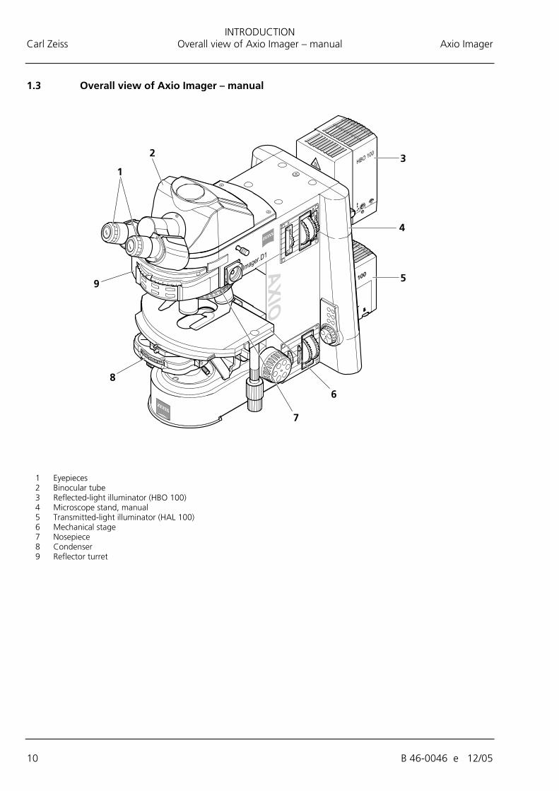
1.3 Overall view of Axio Imager – manual
1 Eyepieces 2 Binocular tube 3 Reflected-light illuminator (HBO 100) 4 Microscope stand, manual 5 Transmitted-light illuminator (HAL 100) 6 Mechanical stage 7 Nosepiece 8 Condenser 9 Reflector turret
INTRODUCTION Axio Imager Overall view of Axio Imager - motorized Carl Zeiss
B 46-0046 e 12/05 11
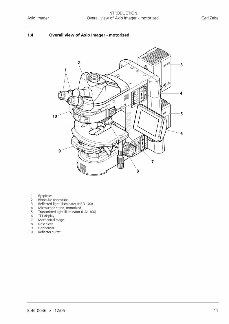
1.4 Overall view of Axio Imager - motorized
1 Eyepieces 2 Binocular phototube 3 Reflected-light illuminator (HBO 100) 4 Microscope stand, motorized 5 Transmitted-light illuminator (HAL 100) 6 TFT display 7 Mechanical stage 8 Nosepiece 9 Condenser 10 Reflector turret
INSTRUMENT DECRIPTION Carl Zeiss Name and intended use Axio Imager
12 B 46-0046 e 12/05
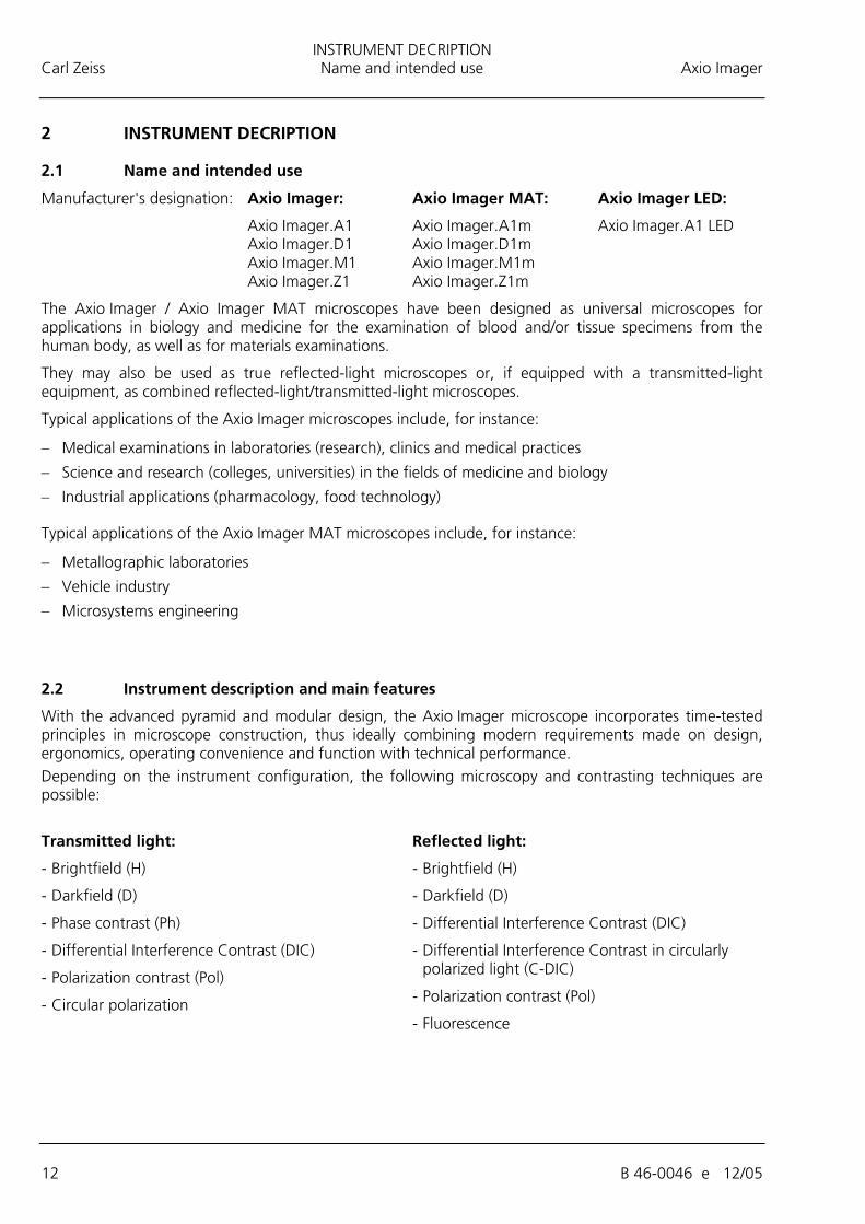
2 INSTRUMENT DECRIPTION
2.1 Name and intended use
Manufacturer's designation: Axio Imager: Axio Imager MAT: Axio Imager LED:
Axio Imager.A1 Axio Imager.A1m Axio Imager.A1 LED Axio Imager.D1 Axio Imager.D1m Axio Imager.M1 Axio Imager.M1m Axio Imager.Z1 Axio Imager.Z1m
The Axio Imager / Axio Imager MAT microscopes have been designed as universal microscopes for applications in biology and medicine for the examination of blood and/or tissue specimens from the human body, as well as for materials examinations.
They may also be used as true reflected-light microscopes or, if equipped with a transmitted-light equipment, as combined reflected-light/transmitted-light microscopes.
Typical applications of the Axio Imager microscopes include, for instance:
− Medical examinations in laboratories (research), clinics and medical practices
− Science and research (colleges, universities) in the fields of medicine and biology
− Industrial applications (pharmacology, food technology)
Typical applications of the Axio Imager MAT microscopes include, for instance:
− Metallographic laboratories
− Vehicle industry
− Microsystems engineering
2.2 Instrument description and main features
With the advanced pyramid and modular design, the Axio Imager microscope incorporates time-tested principles in microscope construction, thus ideally combining modern requirements made on design, ergonomics, operating convenience and function with technical performance. Depending on the instrument configuration, the following microscopy and contrasting techniques are possible:
Transmitted light: Reflected light:
- Brightfield (H)
- Darkfield (D)
- Phase contrast (Ph)
- Differential Interference Contrast (DIC)
- Polarization contrast (Pol)
- Circular polarization
- Brightfield (H)
- Darkfield (D)
- Differential Interference Contrast (DIC)
- Differential Interference Contrast in circularly polarized light (C-DIC)
- Polarization contrast (Pol)
- Fluorescence
INSTRUMENT DECRIPTION Axio Imager Equipment and compatibility table Carl Zeiss
B 46-0046 e 12/05 13
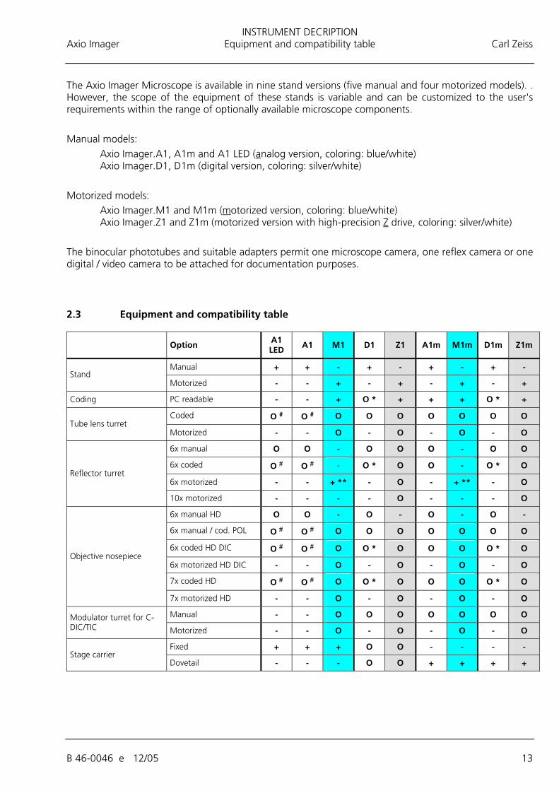
The Axio Imager Microscope is available in nine stand versions (five manual and four motorized models). . However, the scope of the equipment of these stands is variable and can be customized to the user's requirements within the range of optionally available microscope components. Manual models:
Axio Imager.A1, A1m and A1 LED (analog version, coloring: blue/white) Axio Imager.D1, D1m (digital version, coloring: silver/white)
Motorized models:
Axio Imager.M1 and M1m (motorized version, coloring: blue/white) Axio Imager.Z1 and Z1m (motorized version with high-precision Z drive, coloring: silver/white)
The binocular phototubes and suitable adapters permit one microscope camera, one reflex camera or one digital / video camera to be attached for documentation purposes.
2.3 Equipment and compatibility table
Option A1 LED
A1 M1 D1 Z1 A1m M1m D1m Z1m
Manual + + - + - + - + - Stand
Motorized - - + - + - + - +
Coding PC readable - - + O * + + + O * +
Coded O # O # O O O O O O O Tube lens turret
Motorized - - O - O - O - O
6x manual O O - O O O - O O
6x coded O # O # - O * O O - O * O
6x motorized - - + ** - O - + ** - O Reflector turret
10x motorized - - - - O - - - O
6x manual HD O O - O - O - O -
6x manual / cod. POL O # O # O O O O O O O
6x coded HD DIC O # O # O O * O O O O * O
6x motorized HD DIC - - O - O - O - O
7x coded HD O # O # O O * O O O O * O
Objective nosepiece
7x motorized HD - - O - O - O - O
Manual - - O O O O O O O Modulator turret for C-DIC/TIC Motorized - - O - O - O - O
Fixed + + + O O - - - - Stage carrier
Dovetail - - - O O + + + +
INSTRUMENT DECRIPTION Carl Zeiss Equipment and compatibility table Axio Imager
14 B 46-0046 e 12/05
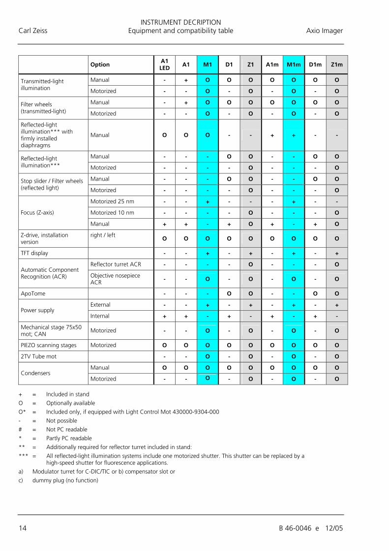
Option A1 LED A1 M1 D1 Z1 A1m M1m D1m Z1m
Manual - + O O O O O O O Transmitted-light illumination Motorized - - O - O - O - O
Manual - + O O O O O O O Filter wheels (transmitted-light) Motorized - - O - O - O - O
Reflected-light illumination*** with firmly installed diaphragms
Manual O O O - - + + - -
Manual - - - O O - - O O Reflected-light illumination*** Motorized - - - - O - - - O
Manual - - - O O - - O O Stop slider / Filter wheels (reflected light) Motorized - - - - O - - - O
Motorized 25 nm - - + - - - + - -
Motorized 10 nm - - - - O - - - O Focus (Z-axis)
Manual + + - + O + - + O
Z-drive, installation version
right / left O O O O O O O O O
TFT display - - + - + - + - +
Reflector turret ACR - - - - O - - - O Automatic Component Recognition (ACR) Objective nosepiece
ACR - - O - O - O - O
ApoTome - - - O O - - O O
External - - + - + - + - + Power supply
Internal + + - + - + - + -
Mechanical stage 75x50 mot; CAN
Motorized - - O - O - O - O
PIEZO scanning stages Motorized O O O O O O O O O
2TV Tube mot - - O - O - O - O
Manual O O O O O O O O O Condensers
Motorized - - O - O - O - O + = Included in stand
O = Optionally available
O* = Included only, if equipped with Light Control Mot 430000-9304-000
- = Not possible
# = Not PC readable
* = Partly PC readable
** = Additionally required for reflector turret included in stand:
*** = All reflected-light illumination systems include one motorized shutter. This shutter can be replaced by a high-speed shutter for fluorescence applications.
a) Modulator turret for C-DIC/TIC or b) compensator slot or
c) dummy plug (no function)
INSTRUMENT DECRIPTION Axio Imager System overview of Axio Imager Carl Zeiss
B 46-0046 e 12/05 15
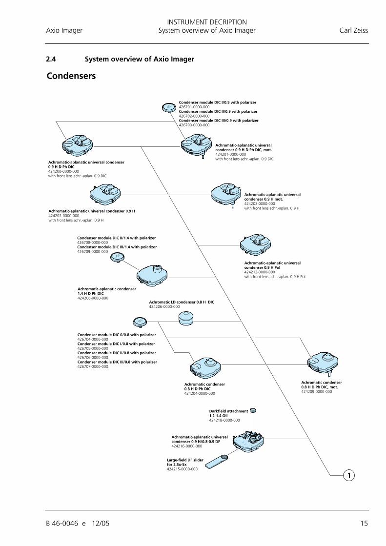
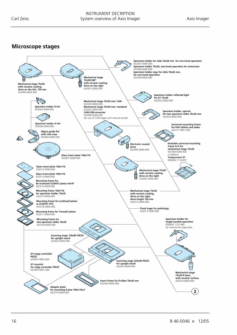
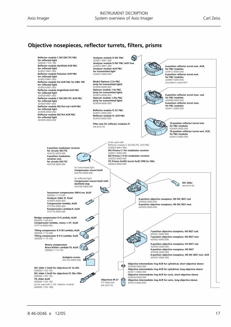
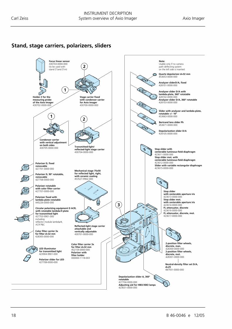
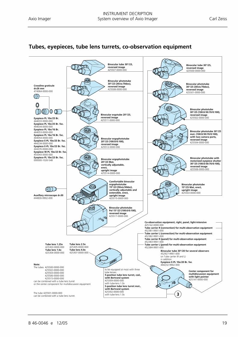
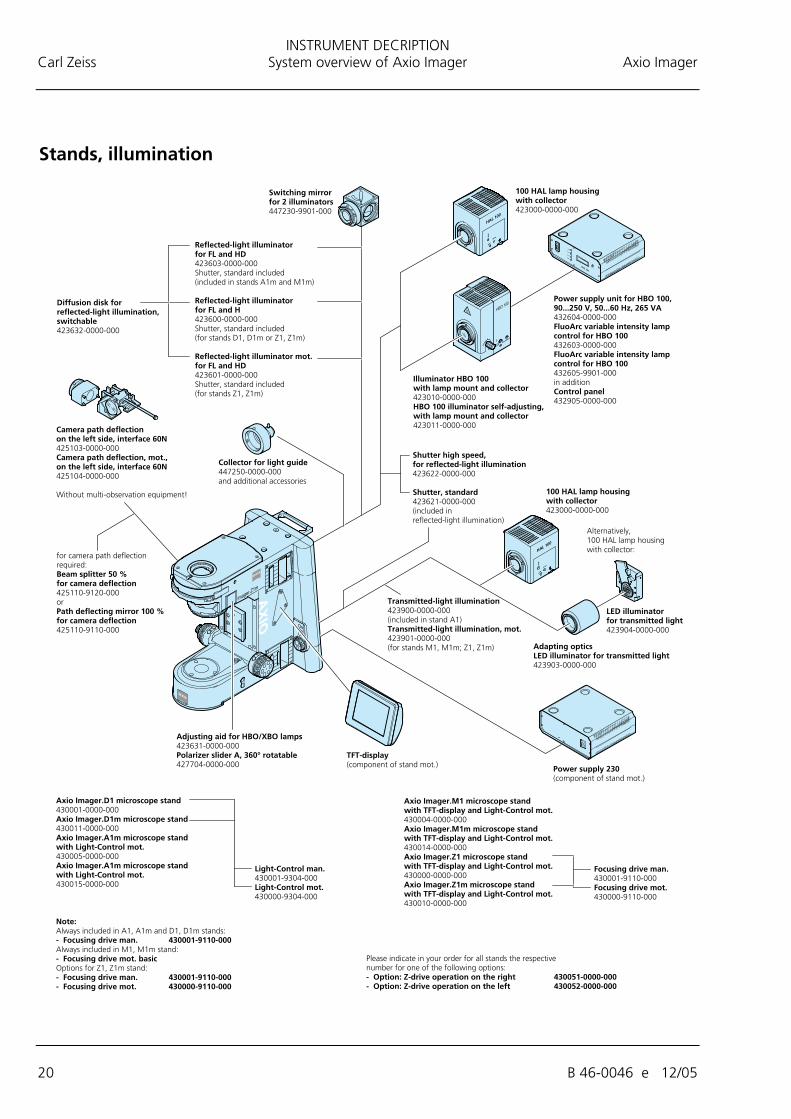
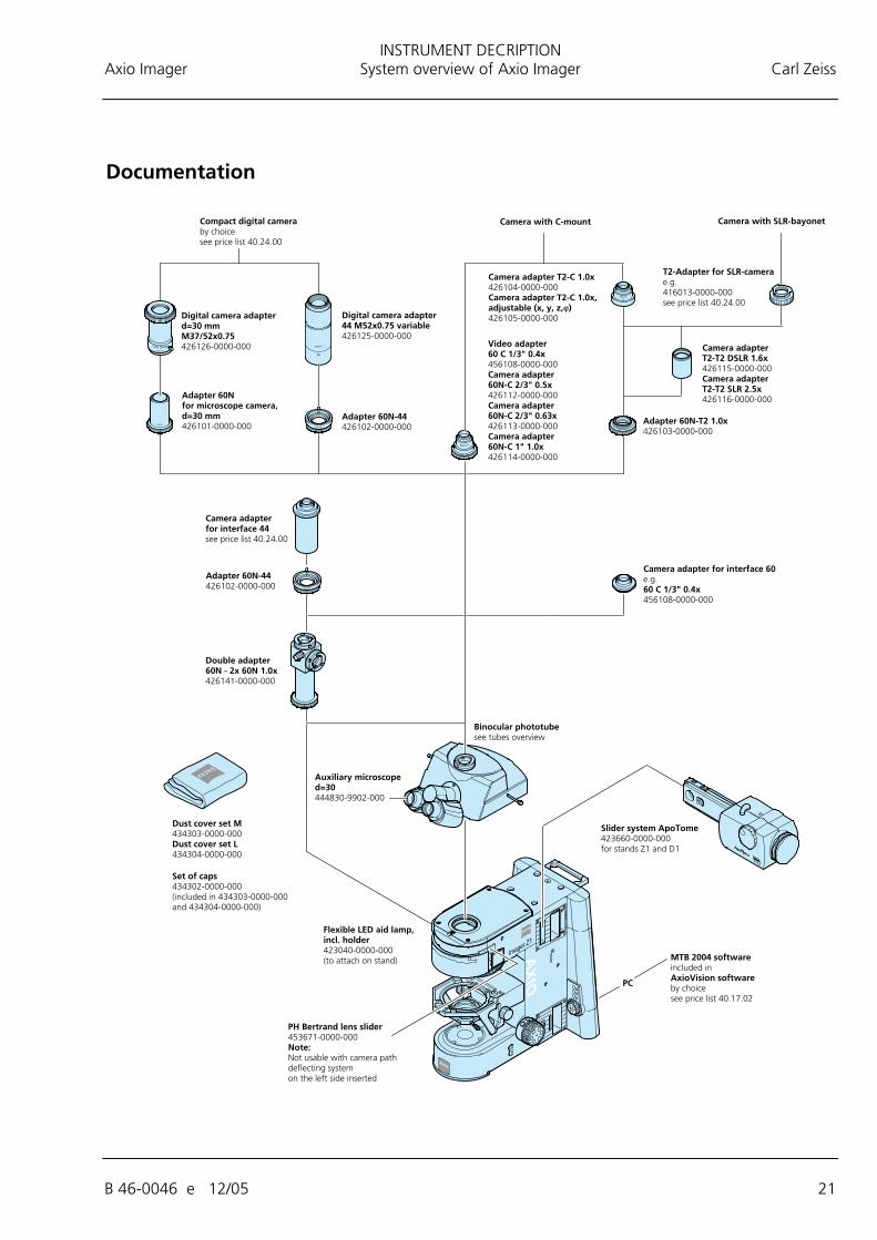
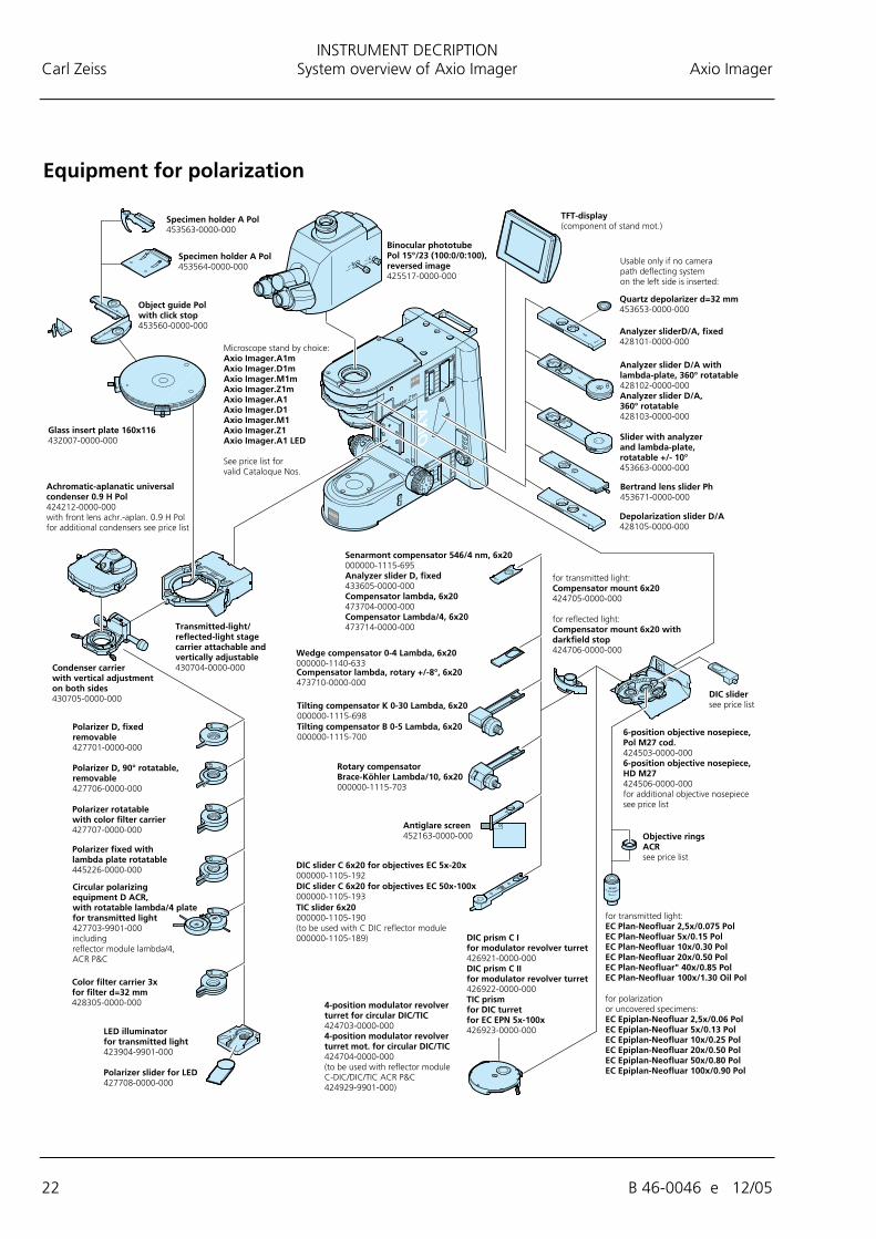
2.4 System overview of Axio Imager
INSTRUMENT DECRIPTION Carl Zeiss System overview of Axio Imager Axio Imager
16 B 46-0046 e 12/05
INSTRUMENT DECRIPTION Axio Imager System overview of Axio Imager Carl Zeiss
B 46-0046 e 12/05 17
INSTRUMENT DECRIPTION Carl Zeiss System overview of Axio Imager Axio Imager
18 B 46-0046 e 12/05
INSTRUMENT DECRIPTION Axio Imager System overview of Axio Imager Carl Zeiss
B 46-0046 e 12/05 19
INSTRUMENT DECRIPTION Carl Zeiss System overview of Axio Imager Axio Imager
20 B 46-0046 e 12/05
INSTRUMENT DECRIPTION Axio Imager System overview of Axio Imager Carl Zeiss
B 46-0046 e 12/05 21
INSTRUMENT DECRIPTION Carl Zeiss System overview of Axio Imager Axio Imager
22 B 46-0046 e 12/05
INSTRUMENT DECRIPTION Axio Imager Objectives Carl Zeiss
B 46-0046 e 12/05 23
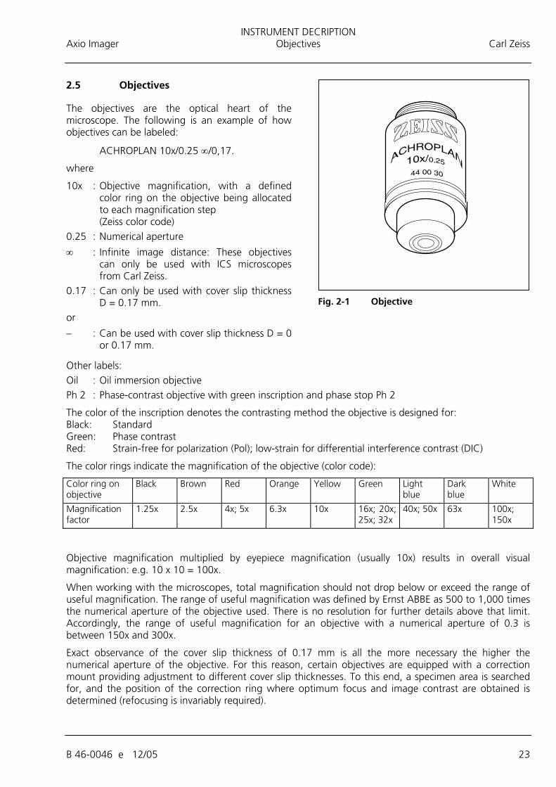
2.5 Objectives
The objectives are the optical heart of the microscope. The following is an example of how objectives can be labeled:
ACHROPLAN 10x/0.25 ∞/0,17.
where
10x : Objective magnification, with a defined color ring on the objective being allocated to each magnification step (Zeiss color code)
0.25 : Numerical aperture
∞ : Infinite image distance: These objectives can only be used with ICS microscopes from Carl Zeiss.
0.17 : Can only be used with cover slip thickness D = 0.17 mm.
or
− : Can be used with cover slip thickness D = 0 or 0.17 mm.
Other labels: Oil : Oil immersion objective Ph 2 : Phase-contrast objective with green inscription and phase stop Ph 2
The color of the inscription denotes the contrasting method the objective is designed for: Black: Standard Green: Phase contrast Red: Strain-free for polarization (Pol); low-strain for differential interference contrast (DIC)
The color rings indicate the magnification of the objective (color code):
Color ring on objective
Black Brown Red Orange Yellow Green Light blue
Dark blue
White
Magnification factor
1.25x 2.5x 4x; 5x 6.3x 10x 16x; 20x; 25x; 32x
40x; 50x 63x 100x; 150x
Objective magnification multiplied by eyepiece magnification (usually 10x) results in overall visual magnification: e.g. 10 x 10 = 100x.
When working with the microscopes, total magnification should not drop below or exceed the range of useful magnification. The range of useful magnification was defined by Ernst ABBE as 500 to 1,000 times the numerical aperture of the objective used. There is no resolution for further details above that limit. Accordingly, the range of useful magnification for an objective with a numerical aperture of 0.3 is between 150x and 300x.
Exact observance of the cover slip thickness of 0.17 mm is all the more necessary the higher the numerical aperture of the objective. For this reason, certain objectives are equipped with a correction mount providing adjustment to different cover slip thicknesses. To this end, a specimen area is searched for, and the position of the correction ring where optimum focus and image contrast are obtained is determined (refocusing is invariably required).
Fig. 2-1 Objective
INSTRUMENT DECRIPTION Carl Zeiss Eyepieces Axio Imager
24 B 46-0046 e 12/05
When immersion objectives are used, the air between the cover slip and the objective is replaced by a liquid, which in most cases is immersion oil. The plastic oiler containing 20 ml of Immersol 581 F® immersion oil (nD = 1.518) is particularly suitable for this purpose.
To prevent oil contamination of the specimen when the nosepiece is turned, the resilient mounts of the immersion objectives can be locked in their lifted position by turning them clockwise (do not forget to unlock them again!).
2.6 Eyepieces
The field-of-view number of the eyepieces PL 10x/25 Br. foc. and E-PL 10x/25 Br. foc. is 25 mm; that of eyepieces W-PL 10x/23 Br. foc. and E-PL 10x/23 Br. foc. is 23 mm.
W-PL and PL in the eyepiece designation refers to the excellent image flatness up to the edge of the field of view.
If required, eyecups for the eyepieces can be ordered under Cat. No. 444801-0000-000.
2.7 Stage micrometers and eyepiece reticles
Measuring and counting using a microscope requires stage micrometers and eyepiece reticles, a selection of which is listed below:
Illustration Designation, technical data Cat. No.
Stage micrometer, positive 5 + 100/100 y D = 0.17 mm Graduation on +y-axis: 5 mm in 5 intervals Graduation on –y-axis: 1 mm in 100 intervals with 2 opposing scales = 10 µm, accuracy ±1µm
474026-0000-000
Crossline micrometer 14:140/d = 26 mm Graduation length = 14 mm Increments = 0.1mm Graduation tolerance ≤ 0.001 mm
454060-0000-000
INSTRUMENT DECRIPTION Axio Imager Stage micrometers and eyepiece reticles Carl Zeiss
B 46-0046 e 12/05 25
Illustration Designation, technical data Cat. No.
Eyepiece reticle /d = 26 mm
For the alignment of the reticle by means of alignment specimen.
474064-0000-000
Crossline micrometer 10:100/d = 26 mm Graduation length = 10 mm Increments = 0.1mm Graduation tolerance ≤ 0.001 mm
474066-9901-000
Net micrometer 12.5x12.5/5;10/d = 26 mm Area 12.5x12.5 mm, divided into 10x10 fields
474068-0000-000
If an eyepiece reticle is used, the binocular tube or the phototube must be equipped with two focusing eyepieces ("foc."), into one of which the eyepiece reticle is to be mounted.
INSTRUMENT DECRIPTION Carl Zeiss Technical data Axio Imager
26 B 46-0046 e 12/05
2.8 Technical data
Dimensions (width x depth x height)
Axio Imager stand, manual with HBO 100 ...................................... approx. 300 mm x 721 mm x 505 mm Axio Imager stand, motorized with HBO 100 and TFT display.......... approx. 390 mm x 721 mm x 505 mm
Weight
Axio Imager, manual/motorized (dependent on equipment)........................................ approx. 18 to 30 kg
Ambient conditions
Transport (in packaging):
Permissible ambient temperature ..........................................................................................-40 to +70 °C
Storage:
Permissible ambient temperature ..........................................................................................+10 to +40°C Permissible relative humidity (no condensation)............................................................ max. 75% at 35 °C
Operation:
Permissible ambient temperature .........................................................................................+10 to +40 °C Permissible relative humidity ........................................................................................ max. 75% at 35 °C Atmospheric pressure ................................................................................................800 hPa to 1060 hPa Altitude .................................................................................................................................max. 2000 m Pollution degree ......................................................................................................................................2 Operating data of Axio Imager, manual with integrated power supply and Axio Imager, motorized with external power supply 230
Operating environment ......................................................................................................... Closed room Protection Class ........................................................................................................................................ I Protection Type ................................................................................................................................. IP 20 Electrical safety............................................................. in compliance with DIN EN 61010-1 (IEC 61010-1)
including CSA and UL directives Overvoltage category............................................................................................................................... II Radio interference suppression ......................................................... in accordance with EN 55011 Class B Noise immunity ............................................................................... in accordance with DIN EN 61326 /A1 Line voltage............................................................................................100 to 127, 200 to 240 V ±10 %
Change of line voltage setting is not required! Line frequency.............................................................................................................................50/60 Hz Power consumption of Axio Imager, manual..........................................................................max. 260 VA Power consumption of Axio Imager, motorized......................................................................max. 280 VA
INSTRUMENT DECRIPTION Axio Imager Technical data Carl Zeiss
B 46-0046 e 12/05 27
Transformer HBO 100
Operating environment.......................................................................................................... Closed room Protection Class ........................................................................................................................................ I Protection Type.................................................................................................................................. IP 20 Line voltage .............................................................................................................100 VAC ... 240 VAC Line frequency .............................................................................................................................50/60 Hz Power consumption when HBO 100 is used................................................................................... 155 VA
Fuses in accordance with IEC 127
Axio Imager microscope stand, manual.............................................................. T 5 A/H / 250V, 5x20 mm Power supply 230 for Axio Imager, mot. .......................................................... T 6.3 A/T / 250V, 5x20 mm Transformer HBO 100.................................................................................................T 2.0 A/H, 5x20 mm
Light sources
Halogen lamp........................................................................................................................ 12 V/100 W Adjustment of light source .................................................................continuous, approx. 3 to 12 V Mercury vapor short-arc lamp .............................................................................................. HBO 103 W/2 Power consumption of HBO 103 W/2 .................................................................................... 100 W
Axio Imager, manual
Stand with manual stage focusing Coarse drive .......................................................................................................... 2 mm/revolution Fine drive ..............................................................................0.2 mm/revolution; 2 µm scale interval Lifting range................................................................................................................. max. 25 mm Height stop ..................................................................................................mechanically adjustable
Achromatic-aplanatic universal condenser 0.9 H D Ph DIC with swivel-type front lens, achromatic-aplanatic 0.9 DIC, for objective magnifications Vobj. < 10x ................................................... front lens 0.9 swiveled out
for objective magnifications Vobj. ≥ 10x ..................................................... front lens 0.9 swiveled in
8-position turret disc Objective change:
Manually ................................................ via 6-position or 7-position nosepiece, HD or HD DIC M27 Change of method modules
Manually ............................................................................................. via 6-position reflector turret
INSTRUMENT DECRIPTION Carl Zeiss Technical data Axio Imager
28 B 46-0046 e 12/05
Axio Imager, motorized
Stand with motorized stage focusing: Mean step size of stepper motor ........................................................ 25 nm ±25 (Axio Imager.M1) .............................................................................................................10 nm ±10 (Axio Imager.Z1) Quick lowering/lifting of stage in operating range ................................................................... 6 mm Lifting range.......................................................................................................................... 25 mm Height stop ....................................................................................................................... electronic Focusing speed..................................................................................................................... variable
Achromatic-aplanatic universal condenser 0.9 H D Ph DIC, mot. with swivel-type front lens, achromatic-aplanatic 0.9 DIC, for objective magnifications Vobj. < 10x ................................................... front lens 0.9 swiveled out
for objective magnifications Vobj. ≥ 10x ......................................................front lens 0.9 swiveled in
8-position turret disc Objective change:
Manually or motorized ............................................................via 6-position or 7-position nosepiece Change of method modules
Manually ............................................................................................. via 6-position reflector turret Motorized ..................................................................... via 6-position or 10-position reflector turret
START-UP Axio Imager Unpacking and installing the microscope Carl Zeiss
B 46-0046 e 12/05 29
3 START-UP
The Axio Imager microscope can be installed, converted and started up by the customer. On request, the microscope is also installed or converted by Zeiss Service with costs.
Before installing and starting-up the microscope, be sure to carefully read the notes on instrument safety (see Chapter 1).
3.1 Unpacking and installing the microscope
The basic instrument is supplied packed to commercial standards in a polyethylene case with cardboard packaging.
It contains the following components: Stand, binocular tube, objectives, eyepieces, condenser, HAL 100 illuminator, microscope mat and various small parts, such as DIC slider, spare lamp, dust cover, tool bag with tools.
The following components are factory-installed to the microscope stand: Mechanical stage, specimen holder, objectives, polarizer, filter holder, reflected-light illumination and adjusting aid for HBO/XBO lamps.
Additional optional accessories are supplied in a separate box.
• Remove all components from the packaging observing the provided instructions for unpacking the instrument.
You can carry the stand using the handle on the rear side of the stand. The second point of holding the stand must never be the stage, as it would be torn out from its holder. Instead, grasp the stand behind the objective nosepiece if reflector turret is firmly installed: Axio Imager.M1, otherwise use grip hollow in blank part.
• Use the delivery form to check the delivered items for completeness.
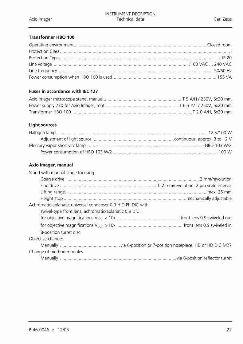
• Place the instrument (3-1/1) onto a vibration-free, flat worktable.
• Unscrew both screws of the carrying handle (on stands with reflector turret only) and remove the carrying handle (3-1/1).
• Screw the coupler plate to the front side using the corresponding screws.
• After you have installed the microscope on the desired place, remove the carrying handle from the rear side as well as the loop holder with loop (3-1/2) from the front side of the stand.
• Keep the original packaging for storage or for returning the instrument to the manufacturer, or dispose of it properly.
Fig. 3-1 Setting up the microscope
START-UP Carl Zeiss Attaching or changing binocular tube or phototube Axio Imager
30 B 46-0046 e 12/05
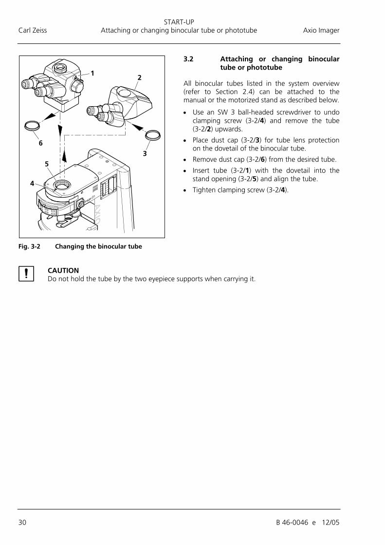
3.2 Attaching or changing binocular tube or phototube
All binocular tubes listed in the system overview (refer to Section 2.4) can be attached to the manual or the motorized stand as described below.
• Use an SW 3 ball-headed screwdriver to undo clamping screw (3-2/4) and remove the tube (3-2/2) upwards.
• Place dust cap (3-2/3) for tube lens protection on the dovetail of the binocular tube.
• Remove dust cap (3-2/6) from the desired tube.
• Insert tube (3-2/1) with the dovetail into the stand opening (3-2/5) and align the tube.
• Tighten clamping screw (3-2/4).
CAUTION Do not hold the tube by the two eyepiece supports when carrying it.
Fig. 3-2 Changing the binocular tube
START-UP Axio Imager Mounting the tube lens turret Carl Zeiss
B 46-0046 e 12/05 31
3.3 Mounting the tube lens turret
• Use SW 3 ball-headed screwdriver to loosen clamping screw (3-3/3) and remove the tube (3-3/1) upward.
• Unscrew four fastening screws (3-3/2), remove coupler plate (3-3/4) upward and store it for any future use.
• Put tube lens turret (3-3/6) onto stand (3-3/5) and screw it down using the four supplied fastening screws (3-3/8).
• Unscrew the tube lens by hand from the tube to be used (3-3/1). Store it in the storage box.
• Insert tube (3-3/1) without tube lens with its dovetail into the mount of the tube lens turret (3-3/6) and tighten clamping screw (3-3/7).
3.4 Inserting eyepieces and auxiliary microscope
• Remove both dust caps (3-4/1 and 4) from the binocular tube.
• Remove both eyepieces (3-4/2) from their cases and insert them into the binocular tube as far as they will go.
• The auxiliary microscope (3-4/3) can be inserted into one of the eyepiece sockets of the binocular tube in place of an eyepiece. It is used to view aperture diaphragm, phase and dark-field stops and to center phase and dark-field stops. Focusing on these diaphragms and stops is possible by means of the adjustable eye lens, which can then be locked by means of the clamp screw.
Fig. 3-3 Mounting the tube lens turret
Fig. 3-4 Inserting eyepieces
START-UP Carl Zeiss Inserting eyepieces and auxiliary microscope Axio Imager
32 B 46-0046 e 12/05
3.4.1 Inserting the eyepiece reticle
The PL 10x/23 Br. foc eyepieces are intended for use with eyepiece reticles.
The slight image shift caused by the additional path through glass is taken into account on the diopter scale by the fact that the zero point position is indicated not by the white dot (3-5/W), but the red dot (3-5/R).
The eyepiece reticles (3-5/3) have been adhered to screw-in mounts (3-5/4) by the manufacturer for easy replacement. Complete mounts with reticles adhered can be ordered directly from Zeiss.
To change the mount, proceed as follows:
• Unscrew the existing mount (3-5/4) with eyepiece reticle (3-5/3) from the eyepiece. Replace it with a new mount containing the eyepiece reticle required.
If you insert eyepiece reticles into the unscrewed mount, take care to ensure that the labeling is visible in the eyepiece the right way up after insertion.
Crossline reticles are to be inserted analogously in the eyepiece (for polarization applications).
3.4.2 Compensation of ametropia when eyepiece reticles are used
Correct use of an eyepiece reticle requires two focusing eyepieces, e.g. PL 10x/23 Br. foc, to enable the user to compensate for differences in the visual acuity of his or her eyes.
• Use the focusing lens of the adjustable eyepiece to focus on the line figure of the eyepiece reticle.
• Viewing through the eyepiece, use the focusing drive to focus on the microscope image of a specimen placed on the stage.
• As soon as the microscope image and the eyepiece reticle are focused in the above eyepiece, turn the focusing eye lens of the second eyepiece to focus the microscope image for the second eye.
On having done this, both microscopic images and that of the eyepiece reticle are focused.
From this point in time on, you should focus only with the focusing drive.
Fig. 3-5 Inserting eyepiece reticles
START-UP Axio Imager Setting the interpupillary distance on the binocular tube Carl Zeiss
B 46-0046 e 12/05 33
3.4.3 Inserting the fold-over eyecups
The eyepieces have a rubber eyeglass protection ring to prevent scratches on spectacles. The protection rings can be replaced with fold-over eyecups when required.
• Remove the eyeglass protection rings (3-5/2) from the eyepieces and attach the eyecups (3-5/1).
• Sometimes the eyeglass protection rings are seated very tightly in the eyepiece groove, so you may need a blunt object (stick) to prod them off.
3.5 Setting the interpupillary distance on the binocular tube
• To adjust the eyepiece distance to your individual interpupillary distance, swing the eyepiece tubes symmetrically toward or away from one another (Fig. 3-6).
The adjustment of the interpupillary distance is correct when you see only one round image while looking through the two eyepieces!
3.6 Setting the viewing height
• The viewing height can be adjusted to individual requirements by swiveling the eyepiece tubes up (3-7/A) or down (3-7/B).
The ergonomic binocular tubes (425511-0000-000, 425512-0000-000 und 425515-0000-000) provide continuous height adjustment over a range of 50 mm. Adjustment is by means of the rotating knob.
Fig. 3-6 Setting the interpupillary distance
on the binocular tube
Fig. 3-7 Setting the viewing height on the
binocular tube
START-UP Carl Zeiss Fitting components to the camera port of the binocular phototube Axio Imager
34 B 46-0046 e 12/05
3.7 Fitting components to the camera port of the binocular phototube
Adapter for Interface 60N (external thread M52 x 1)
The Axio Imager uses a new connector type "Interface 60N" to adapt the camera. The known adapters for "Interface 60" (inside diameter 30 mm), however, can also be used further on.
Microscope cameras (e.g. AxioCam of Carl Zeiss), customary SLR cameras (Single Lens Reflex; 35 mm film or digital) or compact digital cameras may be mounted to the camera port.
For your work with photomicrographic devices, please pay attention to the corresponding manuals of the cameras as well.
• Fix the camera adapter 60N (3-8/1; 2) to the camera.
• Remove the dust cap from the camera port.
Please observe the following: The three set screws (SW 3) (3-8/4) at the camera port must jut out neither to the external thread nor to the internal bore hole.
• Attach the pre-assembled unit to the camera port, adjust it and fasten the union nut of the adapter (3-8/1 or 2) fingertight.
Adapter for Interface 60 (plug-in diameter 30 mm)
• Fix the camera adapter 60 (3-8/3) to the camera.
• Remove the dust cap from the camera port.
• Insert the pre-assembled unit in the camera port (do not screw in set screws too deeply).
• Turn clockwise three set screws (SW 3) at the tube (3-8/4) to fasten adapter.
Fig. 3-8 Fitting components to the
phototube
START-UP Axio Imager Screwing in objectives Carl Zeiss
B 46-0046 e 12/05 35
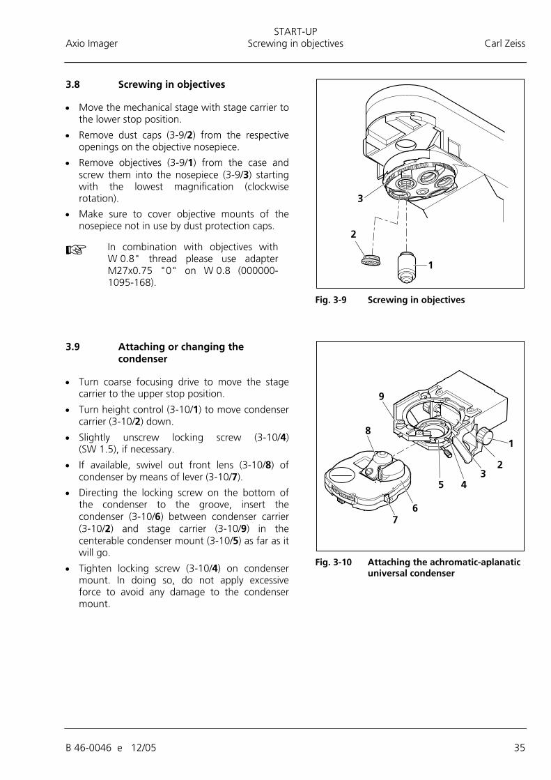
3.8 Screwing in objectives
• Move the mechanical stage with stage carrier to the lower stop position.
• Remove dust caps (3-9/2) from the respective openings on the objective nosepiece.
• Remove objectives (3-9/1) from the case and screw them into the nosepiece (3-9/3) starting with the lowest magnification (clockwise rotation).
• Make sure to cover objective mounts of the nosepiece not in use by dust protection caps.
In combination with objectives with W 0.8" thread please use adapter M27x0.75 "0" on W 0.8 (000000-1095-168).
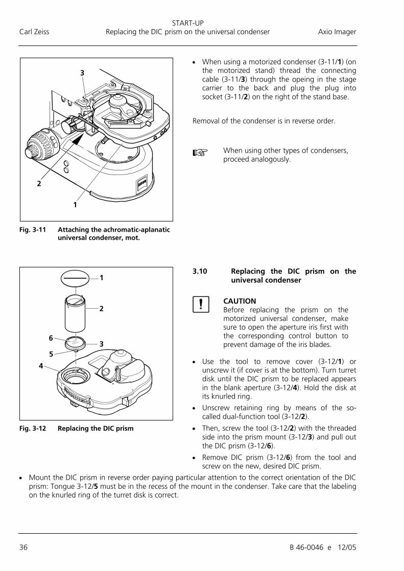
3.9 Attaching or changing the condenser
• Turn coarse focusing drive to move the stage carrier to the upper stop position.
• Turn height control (3-10/1) to move condenser carrier (3-10/2) down.
• Slightly unscrew locking screw (3-10/4) (SW 1.5), if necessary.
• If available, swivel out front lens (3-10/8) of condenser by means of lever (3-10/7).
• Directing the locking screw on the bottom of the condenser to the groove, insert the condenser (3-10/6) between condenser carrier (3-10/2) and stage carrier (3-10/9) in the centerable condenser mount (3-10/5) as far as it will go.
• Tighten locking screw (3-10/4) on condenser mount. In doing so, do not apply excessive force to avoid any damage to the condenser mount.
Fig. 3-9 Screwing in objectives
Fig. 3-10 Attaching the achromatic-aplanatic
universal condenser
START-UP Carl Zeiss Replacing the DIC prism on the universal condenser Axio Imager
36 B 46-0046 e 12/05
• When using a motorized condenser (3-11/1) (on the motorized stand) thread the connecting cable (3-11/3) through the opeing in the stage carrier to the back and plug the plug into socket (3-11/2) on the right of the stand base.
Removal of the condenser is in reverse order.
When using other types of condensers, proceed analogously.
3.10 Replacing the DIC prism on the universal condenser
CAUTION Before replacing the prism on the motorized universal condenser, make sure to open the aperture iris first with the corresponding control button to prevent damage of the iris blades.
• Use the tool to remove cover (3-12/1) or unscrew it (if cover is at the bottom). Turn turret disk until the DIC prism to be replaced appears in the blank aperture (3-12/4). Hold the disk at its knurled ring.
• Unscrew retaining ring by means of the so-called dual-function tool (3-12/2).
• Then, screw the tool (3-12/2) with the threaded side into the prism mount (3-12/3) and pull out the DIC prism (3-12/6).
• Remove DIC prism (3-12/6) from the tool and screw on the new, desired DIC prism.
• Mount the DIC prism in reverse order paying particular attention to the correct orientation of the DIC prism: Tongue 3-12/5 must be in the recess of the mount in the condenser. Take care that the labeling on the knurled ring of the turret disk is correct.
Fig. 3-11 Attaching the achromatic-aplanatic
universal condenser, mot.
Fig. 3-12 Replacing the DIC prism
START-UP Axio ImagerInserting reflector turret, compensator mount 6x20 or 4-position modulator turret Carl Zeiss
B 46-0046 e 12/05 37
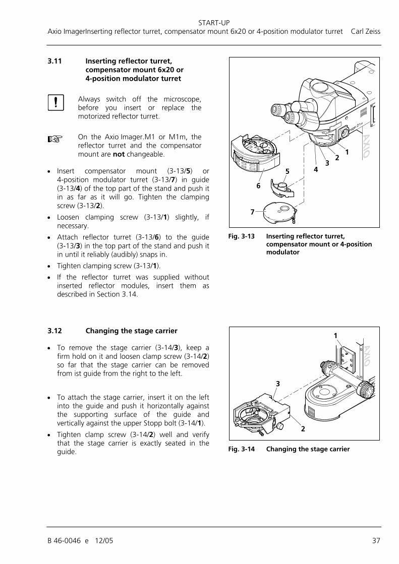
3.11 Inserting reflector turret, compensator mount 6x20 or 4-position modulator turret
Always switch off the microscope, before you insert or replace the motorized reflector turret.
On the Axio Imager.M1 or M1m, the reflector turret and the compensator mount are not changeable.
• Insert compensator mount (3-13/5) or 4-position modulator turret (3-13/7) in guide (3-13/4) of the top part of the stand and push it in as far as it will go. Tighten the clamping screw (3-13/2).
• Loosen clamping screw (3-13/1) slightly, if necessary.
• Attach reflector turret (3-13/6) to the guide (3-13/3) in the top part of the stand and push it in until it reliably (audibly) snaps in.
• Tighten clamping screw (3-13/1).
• If the reflector turret was supplied without inserted reflector modules, insert them as described in Section 3.14.
3.12 Changing the stage carrier
• To remove the stage carrier (3-14/3), keep a firm hold on it and loosen clamp screw (3-14/2) so far that the stage carrier can be removed from ist guide from the right to the left.
• To attach the stage carrier, insert it on the left into the guide and push it horizontally against the supporting surface of the guide and vertically against the upper Stopp bolt (3-14/1).
• Tighten clamp screw (3-14/2) well and verify that the stage carrier is exactly seated in the guide.
Fig. 3-13 Inserting reflector turret,
compensator mount or 4-position modulator
Fig. 3-14 Changing the stage carrier
START-UP Carl Zeiss Equipping 2-position filter wheels 2x, discrete Axio Imager
38 B 46-0046 e 12/05
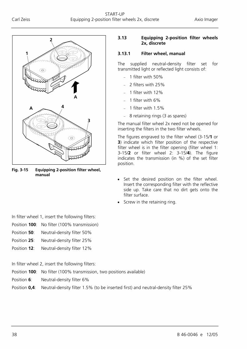
3.13 Equipping 2-position filter wheels 2x, discrete
3.13.1 Filter wheel, manual
The supplied neutral-density filter set for transmitted light or reflected light consists of:
− 1 filter with 50%
− 2 filters with 25%
− 1 filter with 12%
− 1 filter with 6%
− 1 filter with 1.5%
− 8 retaining rings (3 as spares)
The manual filter wheel 2x need not be opened for inserting the filters in the two filter wheels.
The figures engraved to the filter wheel (3-15/1 or 3) indicate which filter position of the respective filter wheel is in the filter opening (filter wheel 1: 3-15/2 or filter wheel 2: 3-15/4). The figure indicates the transmission (in %) of the set filter position.
• Set the desired position on the filter wheel. Insert the corresponding filter with the reflective side up. Take care that no dirt gets onto the filter surface.
• Screw in the retaining ring.
In filter wheel 1, insert the following filters:
Position 100: No filter (100% transmission)
Position 50: Neutral-density filter 50%
Position 25: Neutral-density filter 25%
Position 12: Neutral-density filter 12%
In filter wheel 2, insert the following filters:
Position 100: No filter (100% transmission, two positions available)
Position 6: Neutral-density filter 6%
Position 0,4: Neutral-density filter 1.5% (to be inserted first) and neutral-density filter 25%
Fig. 3-15 Equipping 2-position filter wheel,
manual
START-UP Axio Imager Equipping 2-position filter wheels 2x, discrete Carl Zeiss
B 46-0046 e 12/05 39
3.13.2 Filter wheel, 2-position, motorized
The motorized filter wheel 2x is to be equipped with the same filter set as the manual filter wheel 2x.
To insert the filters in the two filter wheels, the motorized filter wheel 2x must be opened on the corresponding side.
The filter mounts are labeled with the corresponding position numbers 1 to 4 (3-16/1a to 4a and 1b to 4b).
• Loosen both screws (3-16/6 and 7) and remove cover plate (3-16/5 and 6).
• Take care that no dirt gets onto the filter surface.
• Screw in the retaining ring.
• After all filters have been inserted, put on the cover plate and screw it down.
In filter wheel 1 (428301-9901-000; Fig. 3-16), insert the following filters:
Position 1a: No filter (100% transmission)
Position 2a: Neutral-density filter 12%
Position 3a: Neutral-density filter 25%
Position 4a: Neutral-density filter 50%, reflective coating up
In filter wheel 2, insert the following filters:
Position 1b: No filter (100% transmission)
Position 2b: Neutral-density filter 6 %
Position 3b: No filter (100% transmission)
Position 4b: Neutral-density filter 0.5% and neutral-density filter 25%, reflective coating down
Fig. 3-16 Equipping filter wheel 2x,
motorized (only for 428301-9901-000)
START-UP Carl Zeiss Installing and removing P&C reflector modules Axio Imager
40 B 46-0046 e 12/05
3.14 Installing and removing P&C reflector modules
Normally, the reflector turret is factory-equipped with P&C (Push&Click) reflector modules on customer's request. However, the user can also change the equipment of these turrets.
The reflector turret is designed to hold maximally six or ten reflector modules dependent on the model.
3.14.1 Installing a module
• Fold up cover flap (3-17/4) on reflector turret (3-17/3) to the right and unhinge it using the handle (3-17/7) arranged at the left.
• Turn reflector turret until the desired position (position ID labeled on reflector turret) becomes accessible in the mounting hole.
• Holding it by the handles (3-17/5) arranged right and left on the module, insert the module (3-17/6) obliquely from the bottom into the upper spring clips (3-17/1) on the reflector turret.
• Then press the module at the bottom until it snaps securely into the bottom spring clips (3-17/2) of the reflector turret as well.
3.14.2 Removing a module
• Slightly tilting the module, pull it out first from the bottom spring clips and then from the top spring clips. Remove it completely.
• After having removed and installed the reflector modules, hang in the cover flap and let it snap in.
• Turn on the reflector turret by three (6-position reflector turret) or five positions (10-position reflector turret) to swing the just installed module into the optical path.
• After you equipped the turret as desired, label the adhesive labels with the new filter combination and affix them to the corresponding fields on the cover flap.
3.15 Changing the filter set in the reflector module FL P&C
The filter sets for the FL P&C reflector module can be combined and assembled individually by the customer.
Insert only fluorescence filters having a free aperture of ≥ 22 mm, as otherwise the image may be masked. Make sure this requirement is met, when using filters from other manufacturers.
Fig. 3-17 Changing P&C reflector modules
START-UP Axio Imager Changing the filter set in the reflector module FL P&C Carl Zeiss
B 46-0046 e 12/05 41
Filter sets or fully assembled FL P&C reflector modules can be ordered from Carl Zeiss.
• Remove reflector module FL P&C (3-18/3) from the reflector turret and put it down (refer to Section 3.14).
• Use mounting plate (3-18/6) of tool kit to unscrew retaining ring (3-18/1).
• Turn the reflector module round and let the filter (3-18/2 or 5) drop out on a soft surface.
• Insert the barrier filter (emission filter) at (3-18/2), the exciter filter at (3-18/5). Secure both filters by means of retaining rings (3-18/1).
Barrier filter and exciter filter may be provided with a designation and an arrow on their circumference. The arrow indicates the direction the particular filter is to be installed in the reflector module; it must always point inwards (refer to arrows in Fig. 3-18).
To minimize image offset during multiple fluorescence image captures, an additional label can be provided on the barrier filter to indicate the position of the wedge angle.
This label should be aligned to the orientation groove (3-18/4) when you insert the barrier filter in the reflector module used. This is to ensure that the wedge angle of the barrier filters is in the same, defined position in the reflector modules used thus compensating or minimizing the already minimal module-to-module image shift when Zeiss filter sets are used.
If it is necessary to mount filters that do not carry any directional mark (arrow), it is advisable to follow this procedure:
Mount the filters with the reflective dielectric layers in such a way that the reflective layer (3-19/6) on the exciter filter (3-19/5) points outwards (relative to the reflector module). On the barrier filter (3-19/1), the reflective layer (3-19/2) points inwards (Fig. 3-19).
The reflective layer (3-19/4) of the beam splitter (3-19/3) should point downward when in its mounting position.
The arrows (3-19/7) mark the illumination and imaging beam path.
Fig. 3-18 Changing the filter set in reflector
module FL P&C
Fig. 3-19 Installing filter and beam splitter
START-UP Carl Zeiss Changing the beam splitter in the reflector module FL P&C Axio Imager
42 B 46-0046 e 12/05
3.16 Changing the beam splitter in the reflector module FL P&C
In mounting filters and beam splitters, take extreme care to prevent damage to and contamination of the optical components.
We recommend ordering completely equipped FL P&C reflector modules, since changing the beam splitter is quite demanding.
However, if you should choose to change the beam splitter, follow this procedure:
• Remove the FL P&C reflector module from the reflector turret (also refer to Section 3.14.2).
• Undo the two slotted screws (3-20/1) with a screwdriver.
• Hold both halves of the reflector module together (emission half (3-20/2) and excitation half (3-20/3), turn in the position opposite to the installation position and put it down.
• Tip up the excitation half of the module (3-21/1), which now is on top, and remove it from the retaining pins (3-21/5b) on the bottom emission half of the module (3-21/4).
• Remove beam splitter (3-21/2) and spring-loaded frame (3-21/3) from the bottom half of the module.
• Remove the old beam splitter and carefully place the new one onto the spring-loaded frame (3-21/3) with the reflective side facing up and place both parts together into the bottom half of the module. Take care to ensure that the side tongue of the spring-loaded frame is in the appropriate recess in the bottom half of the module.
Fig. 3-20 Changing the beam splitter
Fig. 3-21 Changing the beam splitter
START-UP Axio Imager Mounting the TFT display to the motorized stand Carl Zeiss
B 46-0046 e 12/05 43
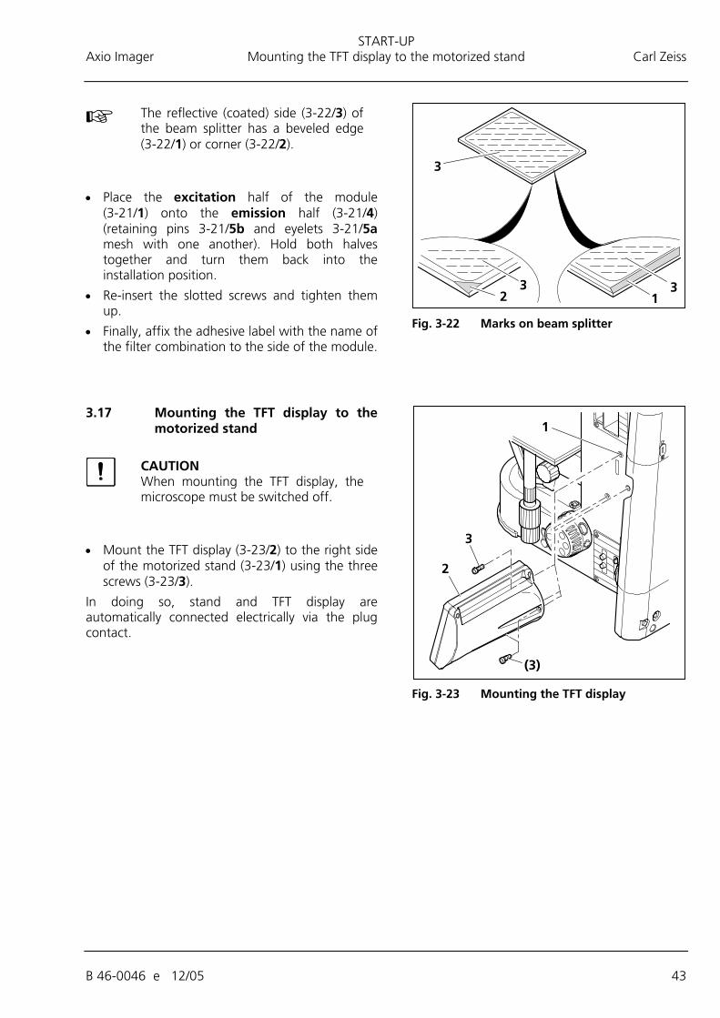
The reflective (coated) side (3-22/3) of the beam splitter has a beveled edge (3-22/1) or corner (3-22/2).
• Place the excitation half of the module (3-21/1) onto the emission half (3-21/4) (retaining pins 3-21/5b and eyelets 3-21/5a mesh with one another). Hold both halves together and turn them back into the installation position.
• Re-insert the slotted screws and tighten them up.
• Finally, affix the adhesive label with the name of the filter combination to the side of the module.
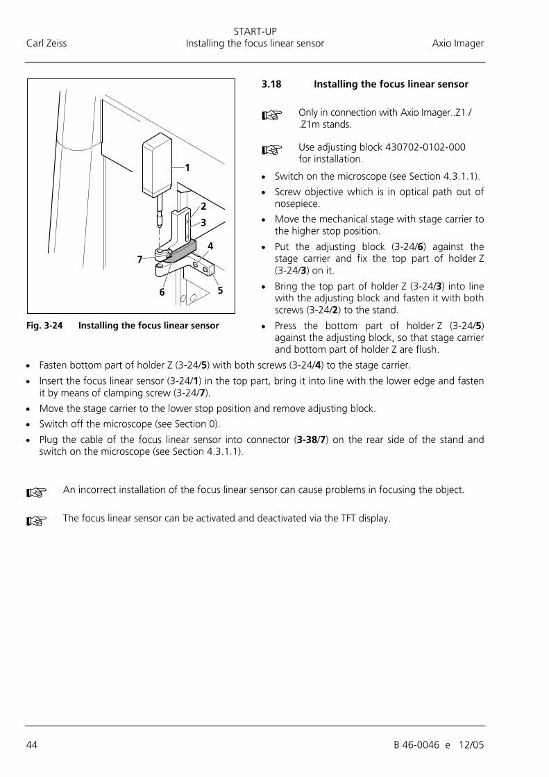
3.17 Mounting the TFT display to the motorized stand
CAUTION When mounting the TFT display, the microscope must be switched off.
• Mount the TFT display (3-23/2) to the right side of the motorized stand (3-23/1) using the three screws (3-23/3).
In doing so, stand and TFT display are automatically connected electrically via the plug contact.
Fig. 3-22 Marks on beam splitter
Fig. 3-23 Mounting the TFT display
START-UP Carl Zeiss Installing the focus linear sensor Axio Imager
44 B 46-0046 e 12/05
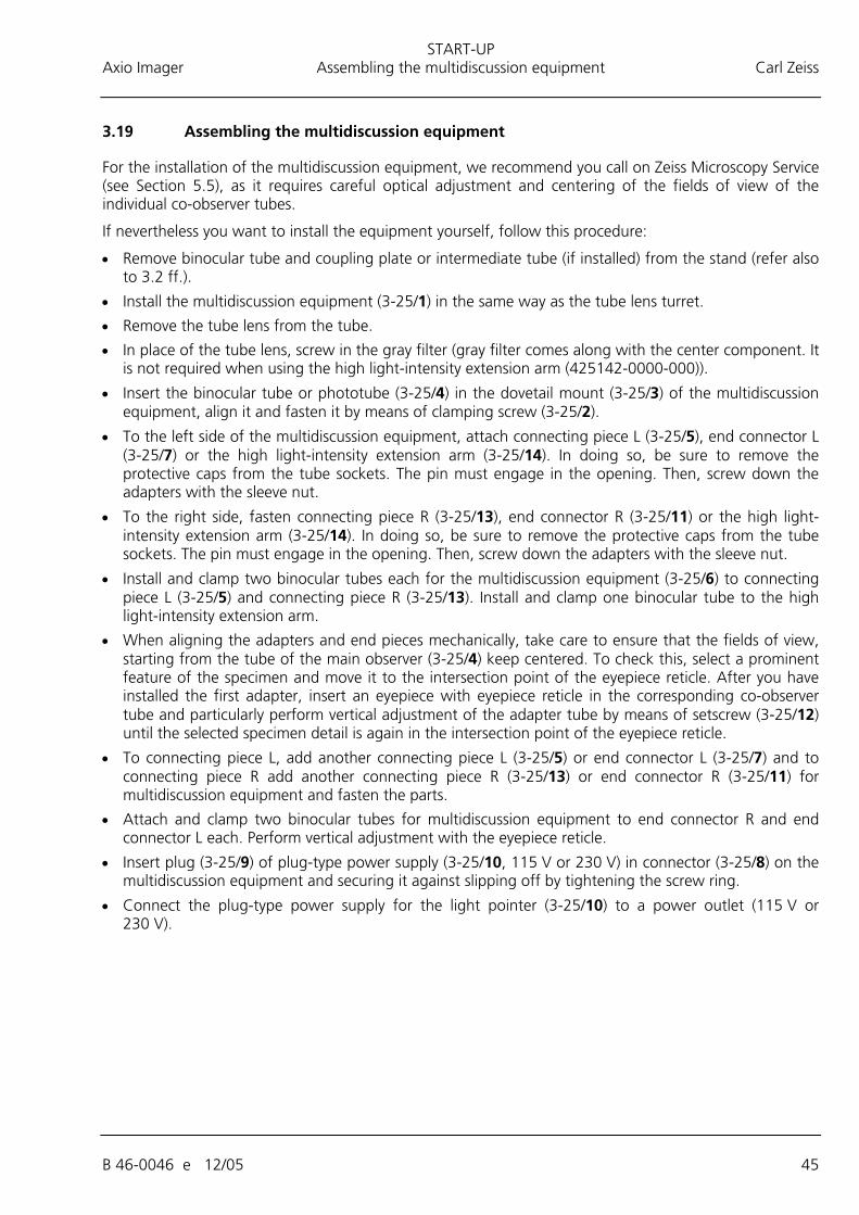
3.18 Installing the focus linear sensor
Only in connection with Axio Imager..Z1 / .Z1m stands.
Use adjusting block 430702-0102-000 for installation.
• Switch on the microscope (see Section 4.3.1.1).
• Screw objective which is in optical path out of nosepiece.
• Move the mechanical stage with stage carrier to the higher stop position.
• Put the adjusting block (3-24/6) against the stage carrier and fix the top part of holder Z (3-24/3) on it.
• Bring the top part of holder Z (3-24/3) into line with the adjusting block and fasten it with both screws (3-24/2) to the stand.
• Press the bottom part of holder Z (3-24/5) against the adjusting block, so that stage carrier and bottom part of holder Z are flush.
• Fasten bottom part of holder Z (3-24/5) with both screws (3-24/4) to the stage carrier.
• Insert the focus linear sensor (3-24/1) in the top part, bring it into line with the lower edge and fasten it by means of clamping screw (3-24/7).
• Move the stage carrier to the lower stop position and remove adjusting block.
• Switch off the microscope (see Section 0).
• Plug the cable of the focus linear sensor into connector (3-38/7) on the rear side of the stand and switch on the microscope (see Section 4.3.1.1).
An incorrect installation of the focus linear sensor can cause problems in focusing the object.
The focus linear sensor can be activated and deactivated via the TFT display.
Fig. 3-24 Installing the focus linear sensor
START-UP Axio Imager Assembling the multidiscussion equipment Carl Zeiss
B 46-0046 e 12/05 45
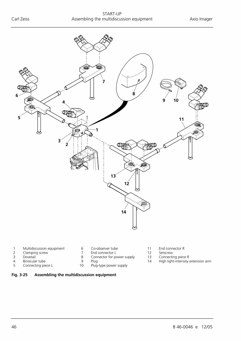
3.19 Assembling the multidiscussion equipment
For the installation of the multidiscussion equipment, we recommend you call on Zeiss Microscopy Service (see Section 5.5), as it requires careful optical adjustment and centering of the fields of view of the individual co-observer tubes.
If nevertheless you want to install the equipment yourself, follow this procedure:
• Remove binocular tube and coupling plate or intermediate tube (if installed) from the stand (refer also to 3.2 ff.).
• Install the multidiscussion equipment (3-25/1) in the same way as the tube lens turret.
• Remove the tube lens from the tube.
• In place of the tube lens, screw in the gray filter (gray filter comes along with the center component. It is not required when using the high light-intensity extension arm (425142-0000-000)).
• Insert the binocular tube or phototube (3-25/4) in the dovetail mount (3-25/3) of the multidiscussion equipment, align it and fasten it by means of clamping screw (3-25/2).
• To the left side of the multidiscussion equipment, attach connecting piece L (3-25/5), end connector L (3-25/7) or the high light-intensity extension arm (3-25/14). In doing so, be sure to remove the protective caps from the tube sockets. The pin must engage in the opening. Then, screw down the adapters with the sleeve nut.
• To the right side, fasten connecting piece R (3-25/13), end connector R (3-25/11) or the high light-intensity extension arm (3-25/14). In doing so, be sure to remove the protective caps from the tube sockets. The pin must engage in the opening. Then, screw down the adapters with the sleeve nut.
• Install and clamp two binocular tubes each for the multidiscussion equipment (3-25/6) to connecting piece L (3-25/5) and connecting piece R (3-25/13). Install and clamp one binocular tube to the high light-intensity extension arm.
• When aligning the adapters and end pieces mechanically, take care to ensure that the fields of view, starting from the tube of the main observer (3-25/4) keep centered. To check this, select a prominent feature of the specimen and move it to the intersection point of the eyepiece reticle. After you have installed the first adapter, insert an eyepiece with eyepiece reticle in the corresponding co-observer tube and particularly perform vertical adjustment of the adapter tube by means of setscrew (3-25/12) until the selected specimen detail is again in the intersection point of the eyepiece reticle.
• To connecting piece L, add another connecting piece L (3-25/5) or end connector L (3-25/7) and to connecting piece R add another connecting piece R (3-25/13) or end connector R (3-25/11) for multidiscussion equipment and fasten the parts.
• Attach and clamp two binocular tubes for multidiscussion equipment to end connector R and end connector L each. Perform vertical adjustment with the eyepiece reticle.
• Insert plug (3-25/9) of plug-type power supply (3-25/10, 115 V or 230 V) in connector (3-25/8) on the multidiscussion equipment and securing it against slipping off by tightening the screw ring.
• Connect the plug-type power supply for the light pointer (3-25/10) to a power outlet (115 V or 230 V).
START-UP Carl Zeiss Assembling the multidiscussion equipment Axio Imager
46 B 46-0046 e 12/05
1 Multidiscussion equipment 6 Co-observer tube 11 End connector R 2 Clamping screw 7 End connector L 12 Setscrew 3 Dovetail 8 Connector for power supply 13 Connecting piece R 4 Binocular tube 9 Plug 14 High light-intensity extension arm 5 Connecting piece L 10 Plug-type power supply
Fig. 3-25 Assembling the multidiscussion equipment
START-UP Axio Imager Connecting to power Carl Zeiss
B 46-0046 e 12/05 47
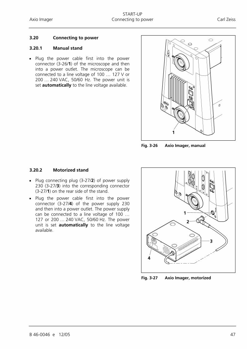
3.20 Connecting to power
3.20.1 Manual stand
• Plug the power cable first into the power connector (3-26/1) of the microscope and then into a power outlet. The microscope can be connected to a line voltage of 100 … 127 V or 200 … 240 VAC, 50/60 Hz. The power unit is set automatically to the line voltage available.
3.20.2 Motorized stand
• Plug connecting plug (3-27/2) of power supply 230 (3-27/3) into the corresponding connector (3-27/1) on the rear side of the stand.
• Plug the power cable first into the power connector (3-27/4) of the power supply 230 and then into a power outlet. The power supply can be connected to a line voltage of 100 … 127 or 200 … 240 VAC, 50/60 Hz. The power unit is set automatically to the line voltage available.
Fig. 3-26 Axio Imager, manual
Fig. 3-27 Axio Imager, motorized
START-UP Carl Zeiss HAL 100 halogen illuminator Axio Imager
48 B 46-0046 e 12/05
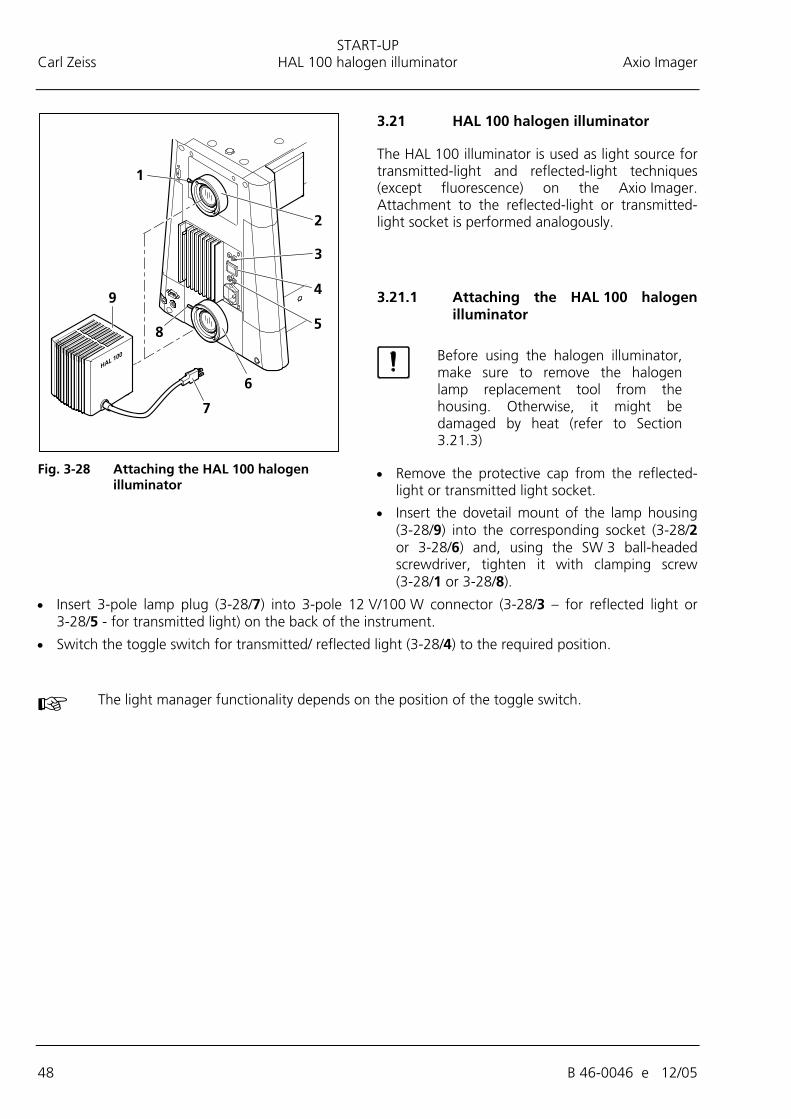
3.21 HAL 100 halogen illuminator
The HAL 100 illuminator is used as light source for transmitted-light and reflected-light techniques (except fluorescence) on the Axio Imager. Attachment to the reflected-light or transmitted-light socket is performed analogously.
3.21.1 Attaching the HAL 100 halogen illuminator
Before using the halogen illuminator, make sure to remove the halogen lamp replacement tool from the housing. Otherwise, it might be damaged by heat (refer to Section 3.21.3)
• Remove the protective cap from the reflected-light or transmitted light socket.
• Insert the dovetail mount of the lamp housing (3-28/9) into the corresponding socket (3-28/2 or 3-28/6) and, using the SW 3 ball-headed screwdriver, tighten it with clamping screw (3-28/1 or 3-28/8).
• Insert 3-pole lamp plug (3-28/7) into 3-pole 12 V/100 W connector (3-28/3 – for reflected light or 3-28/5 - for transmitted light) on the back of the instrument.
• Switch the toggle switch for transmitted/ reflected light (3-28/4) to the required position.
The light manager functionality depends on the position of the toggle switch.
Fig. 3-28 Attaching the HAL 100 halogen
illuminator
START-UP Axio Imager HAL 100 halogen illuminator Carl Zeiss
B 46-0046 e 12/05 49
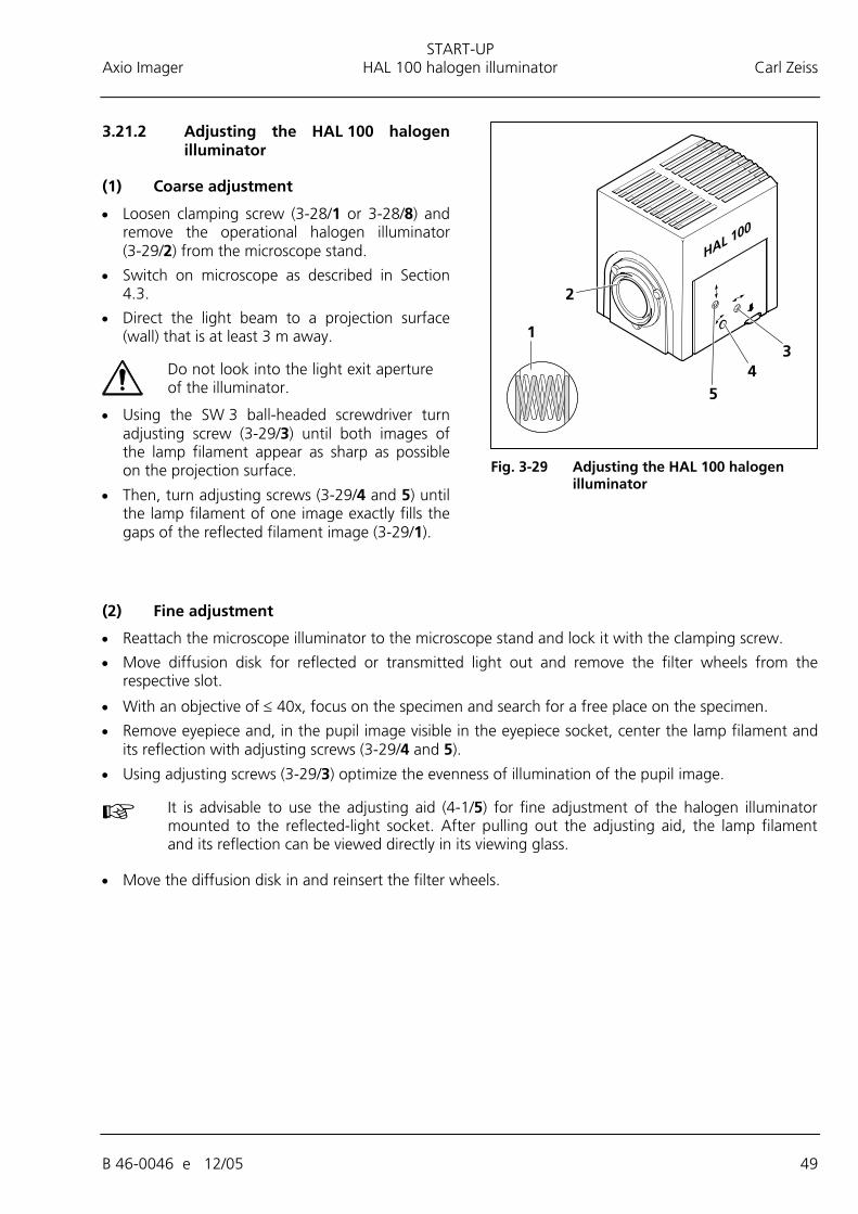
3.21.2 Adjusting the HAL 100 halogen illuminator
(1) Coarse adjustment
• Loosen clamping screw (3-28/1 or 3-28/8) and remove the operational halogen illuminator (3-29/2) from the microscope stand.
• Switch on microscope as described in Section 4.3.
• Direct the light beam to a projection surface (wall) that is at least 3 m away.
Do not look into the light exit aperture of the illuminator.
• Using the SW 3 ball-headed screwdriver turn adjusting screw (3-29/3) until both images of the lamp filament appear as sharp as possible on the projection surface.
• Then, turn adjusting screws (3-29/4 and 5) until the lamp filament of one image exactly fills the gaps of the reflected filament image (3-29/1).
(2) Fine adjustment
• Reattach the microscope illuminator to the microscope stand and lock it with the clamping screw.
• Move diffusion disk for reflected or transmitted light out and remove the filter wheels from the respective slot.
• With an objective of ≤ 40x, focus on the specimen and search for a free place on the specimen.
• Remove eyepiece and, in the pupil image visible in the eyepiece socket, center the lamp filament and its reflection with adjusting screws (3-29/4 and 5).
• Using adjusting screws (3-29/3) optimize the evenness of illumination of the pupil image.
It is advisable to use the adjusting aid (4-1/5) for fine adjustment of the halogen illuminator mounted to the reflected-light socket. After pulling out the adjusting aid, the lamp filament and its reflection can be viewed directly in its viewing glass.
• Move the diffusion disk in and reinsert the filter wheels.
Fig. 3-29 Adjusting the HAL 100 halogen
illuminator
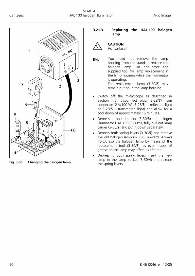
START-UP Carl Zeiss HAL 100 halogen illuminator Axio Imager
50 B 46-0046 e 12/05
3.21.3 Replacing the HAL 100 halogen lamp
CAUTION Hot surface!
You need not remove the lamp housing from the stand to replace the halogen lamp. Do not store the supplied tool for lamp replacement in the lamp housing while the illuminator is operating. The replacement lamp (3-30/8) may remain put on in the lamp housing.
• Switch off the microscope as described in Section 4.3, disconnect plug (3-28/7) from connector12 V/100 W (3-28/3 – reflected light or 3-28/5 – transmitted light) and allow for a cool down of approximately 15 minutes.
• Depress unlock button (3-30/3) of halogen illuminator HAL 100 (3-30/1), fully pull out lamp carrier (3-30/2) and put it down separately.
• Depress both spring levers (3-30/5) and remove the old halogen lamp (3-30/6) upward. Always hold/grasp the halogen lamp by means of the replacement tool (3-30/7), as even traces of grease on the lamp may affect its lifetime.
• Depressing both spring levers insert the new lamp in the lamp socket (3-30/4) and release the spring levers.
Fig. 3-30 Changing the halogen lamp