Embed Size (px)
Citation preview

CLOSED AMPEROMETRIC CELLS OPE
RATI
NG
MAN
UAL
EN
ECL
ECL2H ECL 9ECL 10ECL 11
ECL 1ECL2
ECL 3/SECL 3/NECL 8EBR
ECL SC

SUMMARY
GENERAL SAFETY GUIDELINES .............................................................................3
PURPOSE OF USE AND SAFETY .............................................................................4
ENVIRONMENTAL SAFETY .....................................................................................5
LABELS ..................................................................................................................5
SPARE PARTS .........................................................................................................5
INTRODUCTION .....................................................................................................7Closed amperometric cells ............................................................................................. 7Packaging ..................................................................................................................... 7MODELS ...................................................................................................................... 8ECL1/x .......................................................................................................................... 9ECL3S/10 ...................................................................................................................... 10ECL3N/x ........................................................................................................................ 11ECL8/x .......................................................................................................................... 12ECL2/x .......................................................................................................................... 13ECL2H/x ........................................................................................................................ 14ECL9/x .......................................................................................................................... 15ECL10/x ........................................................................................................................ 16ECL11/x ........................................................................................................................ 17EBR ............................................................................................................................... 18ECLSC ........................................................................................................................... 19Operating principle ........................................................................................................ 20Precautions ................................................................................................................... 20Preparation ECL1/x - ECL3S/10 - ECL3N/x - ECL8/x - ECL2/x - EBR - ECL SC ................... 21Preparation ECL2H/x - ECL9/x - ECL10/x - ECL11/x ......................................................... 23Probe alignment procedure ............................................................................................ 25Cleaning procedure ....................................................................................................... 26Membrane cap replacement ......................................................................................... 28Electrolyte replacement ................................................................................................. 29
MAINTENANCE .....................................................................................................31Maintenance schedule ................................................................................................... 31Maintenance inspection ............................................................................................... 31Probe calibration procedure ........................................................................................... 31
TROUBLESHOOTING ..............................................................................................32

3
This operating instructions contains safety information that if ignored can endanger life or result in serious injury. The original instruction is in Italian. All non-Italian instructions are translations of the original instruction.
Read these instructions carefully before use and keep them for future reference.
Information and specifications on this manual could be uncorrect or could have printing errors.Specifications are subject to change without notice.
Version: R1-07-14
NORME CEEC RULES (STANDARD EC)NORMAS DE LA CE
Direttiva Basso VoltaggioLow Voltage DirectiveDirectiva de baja tensión
Direttiva EMC Compatibilità ElettromagneticaEMC electromagnetic compatibility directiveEMC directiva de compatibilidad electromagnética
2006/95/CE
2004/108/CE
⎬
⎬
Danger! Indicates a hazardous situation which, if not avoided, will result in death or serious injury.
Warning! Indicates a hazardous situation which, if not avoided, could result in death or serious injury.
Important - A practice not related to personal injury or additional information.
⎘ Cross reference - An instance which refers to related information elsewhere in the same document
GENERAL SAFETY GUIDELINESOperating, installing, or maintaining the unit in any way that is not covered in this manual could cause death, serious personal injury, or damage to the equipment.
This manual use the following safety message icon: ICON

4
EQUIPMENT INTENDED FOR THE MEASUREMENT OF CHLORINE (OR ITS ABSENCE) IN WATER.
Do not use in explosive area (EX).Do not use with flammable chemicals.Do not use with radioactive chemicals.
Use the probe in accordance with the data and specifications printed on the label.
Do not modify or use in a manner inconsistent with the provisions of the operating manual.
When using this product with aggressive chemicals observe the regulations concerning the transport and storage of aggressive fluids.
When installing always observe national regulations.
Manufacturer is not liable for any unauthorized use or misuse of this product that may cause injury, damage to persons or materials.
Probes must be serviced and repaired by qualified and authorized personnel only.
Before any operation:• always read chemical Material Safety Data Sheet (MSDS);• always wear protective clothing;• empty and rinse the liquid end before work on a the product which has been
used with hazardous or unknown chemicals.
PURPOSE OF USE AND SAFETY

5
LABELS
Work areaAlways keep the area clean to avoid and/or discover emissions.
Recycling guidelines
EWC code: 16 02 16
Always recycle according to these guidelines:1. If the unit or parts are accepted by an authorized recycling company, then follow local recycling laws and regulations.2. If the unit or parts are not accepted by an authorized recycling company, then return them to the nearest representative.
Waste and emissions regulationsObserve these safety regulations regarding waste and emissions:• Dispose appropriately of all waste.• Handle and dispose of the dosed chemical in compliance with applicable environmental regulations.• Clean up all spills in accordance with safety and environmental procedures.• Report all environmental emissions to the appropriate authorities.
Environmental safety
PROBE’S NAME
CODE: probe code
DESCRIPTION
TECHNICAL DATA
N: quantity
P.N. (part number): serial number
Data matrix “P.N.“(part number)
Data matrixPROBE CODE
DISTRIBUTOR
ECL8/2
CODE: 10806171
10806171
N: PZ 1 P.N.: 13041091800000001 QC PASSED: VA
AMPEROMETRIC CELL FOR TOTAL CHLORINE
CABLE: 1 mCl2: 0-2 mg/l-1000 mV/ppmTEMPERATURE: 1-40°C / 34-104°FPRESSURE: 0-0.5 BARPVC BODY 25
PROBE CODEAMPEROMETRIC CELL FOR TOTAL CHLORINE
Distributor
For spare parts orders or any other communication, refer to the pump’s label.Code (CODE) and serial number (P / N) uniquely identify the probe.
Spare parts
On the box (example)
On the probe (example)

6
Transportation and storage
Storage procedure
An unsuitable transportation or storage can cause damages.
Use original box to pack the probe.
Observe storage conditions also for transportation.
Although packed, always protect the unit against humidity and the action of chemicals.
Before returning the probe to the manufacturer repair service, clean and rinse it. Disassemble the membrane cap and discard electrolyte.
DO NOT DISCARD PACKAGING. USE IT TO RETURN THE PROBE.
Do not assemble the membrane cap with electrolyte until the probe is ready to be inserted in the PEF flow cell with water flowing through it.
The probe MUST NOT be allowed to remain DRY for long periods of time once assembled. Otherwise the probe may become damaged.
To store the probe:
1. After use rinse the probe with fresh water.
2. Check that the micro-holes are not obstructed.
3. Disassemble membrane cap and discard electrolyte.
4. Clean the probe as in “Cleaning procedure”.
5. Dry the probe in the air.
6. Store the probe in the original box, protected against sun, chemicals and humidity.
7. For ECL2H, ECL 9, ECL10 and ECL11 store the membrane cap into the small container filled with the storage chemical.
Transportation and storage temperature ..... 10 - 50°C (32 - 122°F)Humidity .................................................... 95% relative humidity (not condensed)
IMPORTANT
IMPORTANT
IMPORTANT
After a storage period, check the micro-holes are not obstructed from product residues.

7
Closed amperometric cells
Packaging
They are equipped with a special membrane system.ECL1, 3 and 8 work in chlorine water system.Absence of chlorine could damage the probe except for ECL SC probe.The probe has to be installed into a probe holder and connected to a measuring and control instrument.
The packaging will include the following:
• probe with membrane cap (for ECL2H, ECL9, ECL10 and ECL11 membrane cap is supplied into
a small container filled up with electrolyte)
• connector cable
• electrolyte
• abrasive paper (S2)
• operating manual
Probe shaft
Probe tip
Membrane capOring
Transparent
cover
INTRODUCTION
Progettato da: Controllato da: Data:
Edizione Foglio/Esploso_ECL1
Massimo_F Massimo_F 13/06/2013
00
Toll. Gen.±0.05
Peso Lordo: Peso Netto:
Materiale:
1 1
to the instrument to the instrument
Progettato da: Controllato da: Data:
Edizione Foglio/Esploso_ECL9-10-11
Massimo_F Massimo_F 16/06/2014
00
Toll. Gen.±0.05
Peso Lordo: Peso Netto:
Materiale:
1 1
ECL2HECL 9
ECL 10ECL 11
ECL 1ECL2
ECL 3/SECL 3/NECL 8EBR
ECL SC
Double
Oring

8
MODELS • ECL1/x for free chlorine (inorganic)
• ECL3S/10 for free chlorine (organic and inorganic) for fresh water
• ECL3N/x for free chlorine (inorganic) for fresh water
• ECL8/x for total chlorine
• ECL2/x for chlorine dioxide
• ECL2H/x for chlorine dioxide
• ECL9/x for hydrogen peroxyde
• ECL10/x for ozone
• ECL 11/x for peracetic acid
• EBR for bromine
• ECL SC for chlorine absence

9
ECL1/xECL1/x ECL1/x mA
Parameter FREE CHLORINE (INORGANIC)
Measuring range
ECL1/2: 0-2 mg/l (0-2 ppm) resolution: ± 0.001ECL1/5: 0-5 mg/l (0-5 ppm) resolution: ± 0.001ECL1/20: 0-20 mg/l (0-20 ppm) resolution: ± 0.01ECL1/200: 0-200 mg/l (0-200 ppm) resolution: ± 0.1
Output (Output resistance)
0 / -2000 mV (1kΩ) 4 / 20mA uncalibrated
Voltage supply ±5 - ±15 VDC (10 mA) 12 / 30 VDC
Connection 4-pole screw connector 2-pole terminal
Measuring system membrane covered, amperometric 2-electrode system
Ph working range 6-8 pH
Run-in-time first start up: 1 h approx.
Response time T90: 30 sec. approx.
Zero point adjustment
see chapter “Probe alignment”
Slope calibration see chapter “Probe alignment” DPD1 method
Alcalinity 80 ppm
Working temperature
1-40° C (34-104°F)
Temperature compensation
automatically, by an integrated temperature sensor
Max pressure1 bar (14.5 PSI) - 10 mwc [mH2O]no pressure impulses and/or vibration, no depressure
Power supply 4 wires (brown +; white -; green IN; yellow GND) 2 wires
Cable (standard) 1 m (3.28 ft) no cable
Electrolyte mod. ELECL1
Membrane mod. MECL1-2
Working flow 30 l/h
Suitable for probe holder mod.
PEF1, PEF1/E, PEF5, PEF23
Material semipermeable membrane, PVC-U
Storageprobe: frost-protected, dry and without electrolyte (5-40° C)membrane cap: used membrane cap can not be storedelectrolyte: in original bottle, protect from sunlight (5-25°C)
Maintenance
regular control of measuring signalchange of the membrane cap: once a year at min. change electrolyte: every 3-6 monthsSHORTEN THE MAINTENANCE INTERVALS APPROPRIATELY DEPENDING ON WATER QUALITY.
DimensionDiam.: 25 mmLength: 175 mm

10
ECL3S/10ECL3S/10 ECL3S/10 mA
Parameter FREE CHLORINE (ORGANIC AND INORGANIC) FOR FRESH WATER
Measuring range 0-20 mg/l (0-20 ppm) resolution: ± 0.01
Output (Output resistance)
0 / -2000 mV (1kΩ) 4 / 20mA uncalibrated
Voltage supply ±5 - ±15 VDC (10 mA) 12 / 30 VDC
Connection 4-pole screw connector 2-pole terminal
Measuring system membrane covered, amperometric potentiostatic 3-electrode system
Ph working range 4-12 pH, highly reduced dependance on pH value
Run-in-time first start up: 2 h approx.
Response time T90: 2 min. approx.
Zero point adjustment
see chapter “Probe alignment”
Slope calibration see chapter “Probe alignment” DPD1 method
Alcalinity 80 ppm
Working temperature
1-40° C (34-104°F)
Temperature compensation
automatically, by an integrated temperature sensor
Max pressure0.5 bar (7 PSI) - 5 mwc [mH2O]no pressure impulses and/or vibration, no depressure
Power supply 4 wires (brown +; white -; green IN; yellow GND) 2 wires
Cable (standard) 1 m (3.28 ft) no cable
Electrolyte mod. ELECL3S (for ECL3S probe for salt water ECL3S/SEA)
Membrane mod. MECL3
Working flow 30 l/h
Suitable for probe holder mod.
PEF1, PEF1/E, PEF5, PEF23
Material microporous hydrophilic membrane, PVC-U, stainless steel 1.4571
Storageprobe: frost-protected, dry and without electrolyte (5-40° C)membrane cap: used membrane cap can not be storedelectrolyte: in original bottle, protect from sunlight (5-25°C)
Maintenance
regular control of measuring signalchange of the membrane cap: once a year at min. change electrolyte: every 3-6 monthsSHORTEN THE MAINTENANCE INTERVALS APPROPRIATELY DEPENDING ON WATER QUALITY.
DimensionDiam.: 25 mmLength: 175 mm

11
ECL3N/xECL3N/x ECL3N/x mA
Parameter FREE CHLORINE (INORGANIC) FOR FRESH WATER
Measuring rangeECL3N/2: 0-2 mg/l (0-2 ppm) resolution: ± 0.001ECL3N/10: 0-20 mg/l (0-20 ppm) resolution: ± 0.01ECL3N/200: 0-200 mg/l (0-200 ppm) resolution: ± 0.1
Output (Output resistance)
ECL3N/2: 0 / -2000 mV (1kΩ)ECL3N/10: 0 / -2000 mV (1kΩ)ECL3N/200: 0 / -2000 mV (1kΩ)
4 / 20mA uncalibrated
Voltage supply ±5 - ±15 VDC (10 mA) 12 / 30 VDC
Connection 4-pole screw connector 2-pole terminal
Measuring system membrane covered, amperometric potentiostatic 3-electrode system
Ph working range4-9 pH, reduced dependance on pH value. When the pH value increases, the measured signal decreases at about 10% per pH unit.
Run-in-time first start up: 2 h approx.
Response time T90: 2 min. approx.
Zero point adjustment
see chapter “Probe alignment”
Slope calibration see chapter “Probe alignment” DPD1 method
Alcalinity 80 ppm
Working temperature
1-40° C (34-104°F)
Temperature compensation
automatically, by an integrated temperature sensor
Max pressure0.5 bar (7 PSI) - 5 mwc [mH2O]no pressure impulses and/or vibration, no depressure
Power supply 4 wires (brown +; white -; green IN; yellow GND) 2 wires
Cable (standard) 1 m (3.28 ft) no cable
Electrolyte mod. ELECL3N
Membrane mod. MECL3
Working flow 30 l/h
Suitable for probe holder mod.
PEF1, PEF1/E, PEF5, PEF23
Material microporous hydrophilic membrane, PVC-U, stainless steel 1.4571
Storageprobe: frost-protected, dry and without electrolyte (5-40° C)membrane cap: used membrane cap can not be storedelectrolyte: in original bottle, protect from sunlight (5-25°C)
Maintenance
regular control of measuring signalchange of the membrane cap: once a year at min. change electrolyte: every 3-6 monthsSHORTEN THE MAINTENANCE INTERVALS APPROPRIATELY DEPENDING ON WATER QUALITY.
DimensionDiam.: 25 mmLength: 175 mm

12
ECL8/xECL8/x ECL8/x mA
Parameter TOTAL CHLORINE
Measuring rangeECL8/2: 0-2 mg/l (0-2 ppm) resolution: ± 0.001ECL8/20: 0-20 mg/l (0-20 ppm) resolution: ± 0.01
Output (Output resistance)
ECL8/2: 0 / -2000 mV (1kΩ) ECL8/20: 0 / -2000 mV (1kΩ)
4 / 20mA uncalibrated
Voltage supply ±5 - ±15 VDC (10 mA) 12 / 30 VDC
Connection 4-pole screw connector 2-pole terminal
Measuring system membrane covered, amperometric potentiostatic 3-electrode system
Ph working range4-12 pH, reduced dependance on pH value. When the pH value increases, the measured signal decreases at about 10% per pH unit.
Run-in-time first start up: 2 h approx.
Response time T90: 2 min. approx.
Zero point adjustment
see chapter “Probe alignment”
Slope calibration see chapter “Probe alignment” DPD4 method
Alcalinity 80 ppm
Working temperature
1-40° C (34-104°F)
Temperature compensation
automatically, by an integrated temperature sensor
Max pressure0.5 bar (7 PSI) - 5 mwc [mH2O]no pressure impulses and/or vibration, no depressure
Power supply 4 wires (brown +; white -; green IN; yellow GND) 2 wires
Cable (standard) 1 m (3.28 ft) no cable
Electrolyte mod. ELECL8
Membrane mod. MECL8/2 or MECL8/20
Working flow 30 l/h
Suitable for probe holder mod.
PEF1, PEF1/E, PEF5, PEF23
Material microporous hydrophilic membrane, PVC-U, stainless steel 1.4571
Storageprobe: frost-protected, dry and without electrolyte (5-40° C)membrane cap: used membrane cap can not be storedelectrolyte: in original bottle, protect from sunlight (5-25°C)
Maintenance
regular control of measuring signalchange of the membrane cap: once a year at min. change electrolyte: every 3-6 monthsSHORTEN THE MAINTENANCE INTERVALS APPROPRIATELY DEPENDING ON WATER QUALITY.
DimensionDiam.: 25 mmLength: 175 mm

13
ECL2/xParameter CHLORINE DIOXIDE
Measuring rangeECL2/2: 0-2 mg/l (0-2 ppm) resolution: ± 0.001ECL2/20: 0-20 mg/l (0-20 ppm) resolution: ± 0.01
Output (Output resistance)
ECL2/2: 0 / -2000 mV (1kΩ) ECL2/20: 0 / -2000 mV (1kΩ)
Voltage supply ±5 - ±15 VDC (10 mA)
Connection 4-pole screw connector
Measuring system membrane covered, amperometric 2-electrode system
Ph working range 1-11 pH
Run-in-time first start up: 1 h approx.
Response time T90: 15 sec.. approx.
Zero point adjustment see chapter “Probe alignment”
Slope calibration see chapter “Probe alignment”
Alcalinity 80 ppm
Working temperature 1-40° C (34-104°F)
Temperature compensation
automatically, by an integrated temperature sensor
Max pressure1 bar (14.5 PSI) - 10 mwc [mH2O]no pressure impulses and/or vibration, no depressure
Power supply 4 wires (brown +; white -; green IN; yellow GND)
Cable (standard) 1 m (3.28 ft)
Electrolyte mod. ELECL2
Membrane mod. MECL1-2
Working flow 30 l/h
Suitable for probe holder mod.
PEF1, PEF1/E, PEF5, PEF23
Material semipermeable membrane, PVC-U
Storageprobe: frost-protected, dry and without electrolyte (5-40° C)membrane cap: used membrane cap can not be storedelectrolyte: in original bottle, protect from sunlight (5-25°C)
Maintenance
regular control of measuring signalchange of the membrane cap: once a year at min. change electrolyte: every 3-6 monthsSHORTEN THE MAINTENANCE INTERVALS APPROPRIATELY DEPENDING ON WATER QUALITY.
DimensionDiam.: 25 mmLength: 175 mm
14
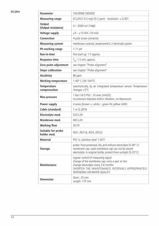
ECL2H/xParameter CHLORINE DIOXIDE
Measuring range ECL2H/2: 0-2 mg/l (0-2 ppm) resolution: ± 0.001
Output (Output resistance)
0 / -2000 mV (1kΩ)
Voltage supply ±5 - ±15 VDC (10 mA)
Connection 4-pole screw connector
Measuring system membrane covered, amperometric 2-electrode system
Ph working range 1-11 pH
Run-in-time first start up: 1 h approx.
Response time T90: 1.5 min. approx.
Zero point adjustment see chapter “Probe alignment”
Slope calibration see chapter “Probe alignment”
Alcalinity 80 ppm
Working temperature 1-40° C (34-104°F)
Temperature compensation
automatically, by an integrated temperature sensor. Temperature changes <5°C
Max pressure1 bar (14.5 PSI) - 10 mwc [mH2O]no pressure impulses and/or vibration, no depressure
Power supply 4 wires (brown +; white -; green IN; yellow GND)
Cable (standard) 1 m (3.28 ft)
Electrolyte mod. ELECL2H
Membrane mod. MECL2H
Working flow 30 l/h
Suitable for probe holder mod.
PEF1, PEF1/E, PEF5, PEF23
Material PVC-U, stainless steel 1.4571
Storageprobe: frost-protected, dry and without electrolyte (5-40° C)membrane cap: used membrane cap can not be storedelectrolyte: in original bottle, protect from sunlight (5-25°C)
Maintenance
regular control of measuring signalchange of the membrane cap: once a year at min. change electrolyte: every 3-6 monthsSHORTEN THE MAINTENANCE INTERVALS APPROPRIATELY DEPENDING ON WATER QUALITY.
DimensionDiam.: 25 mmLength: 175 mm

15
ECL9/xParameter HYDROGEN PEROXIDE
Measuring rangeECL9/200: 0-200 mg/l (0-200 ppm) resolution: ± 0.1ECL9/2000: 0-2000 mg/l (0-2000 ppm) resolution: ± 1
Output (Output resistance)
0 / -2000 mV (1kΩ)
Voltage supply±5 - ±12.5 VDC 10 - 25 VDC 25 mA
Connection 4-pole screw connector
Measuring system membrane covered, amperometric 2-electrode system
Ph working range 2-11 pH
Run-in-time first start up: 3 h approx.
Response time T90: 10 min. approx.
Zero point adjustment see chapter “Probe alignment”
Slope calibration see chapter “Probe alignment”
Alcalinity 80 ppm
Working temperature 1-40° C (34-104°F)
Temperature compensation
automatically, by an integrated temperature sensor
Max pressure1 bar (14.5 PSI) - 10 mwc [mH2O]no pressure impulses and/or vibration, no depressure
Power supply 4 wires (brown +; white -; green IN; yellow GND)
Cable (standard) 1 m (3.28 ft)
Electrolyte mod. ELECL9
Membrane mod. MECL9
Working flow 30 l/h
Suitable for probe holder mod.
PEF1, PEF1/E, PEF5, PEF23
Material PVC-U, stainless steel 1.4571
Storageprobe: frost-protected, dry and without electrolyte (5-40° C)membrane cap: used membrane cap can not be storedelectrolyte: in original bottle, protect from sunlight (5-25°C)
Maintenance
regular control of measuring signalchange of the membrane cap: once a year at min. change electrolyte: every 3-6 monthsSHORTEN THE MAINTENANCE INTERVALS APPROPRIATELY DEPENDING ON WATER QUALITY.
DimensionDiam.: 25 mmLength: 175 mm

16
ECL10/xParameter OZONE
Measuring rangeECL10/1: 0-0,5 mg/l (0-0,5 ppm) resolution: ± 0.001ECL10/10: 0-10 mg/l (0-10 ppm) resolution: ± 0.01
Output (Output resistance)
ECL10/1: 0 / -1000 mV (1kΩ) ECL10/10: 0 / -1000 mV (1kΩ)
Voltage supply±5 - ±15 VDC 10 mA
Connection 4-pole screw connector
Measuring system membrane covered, amperometric 2-electrode system
Ph working range 2-11 pH
Run-in-time first start up: 1 h approx.
Response time T90: 50 sec. approx.
Zero point adjustment see chapter “Probe alignment”
Slope calibration see chapter “Probe alignment”
Alcalinity 80 ppm
Working temperature 1-40° C (34-104°F)
Temperature compensation
automatically, by an integrated temperature sensor
Max pressure1 bar (14.5 PSI) - 10 mwc [mH2O]no pressure impulses and/or vibration, no depressure
Power supply 4 wires (brown +; white -; green IN; yellow GND)
Cable (standard) 1 m (3.28 ft)
Electrolyte mod. ELECL10
Membrane mod. MECL10
Working flow 30 l/h
Suitable for probe holder mod.
PEF1, PEF1/E, PEF5, PEF23
Material PVC-U, stainless steel 1.4571
Storageprobe: frost-protected, dry and without electrolyte (5-40° C)membrane cap: used membrane cap can not be storedelectrolyte: in original bottle, protect from sunlight (5-25°C)
Maintenance
regular control of measuring signalchange of the membrane cap: once a year at min. change electrolyte: every 3-6 monthsSHORTEN THE MAINTENANCE INTERVALS APPROPRIATELY DEPENDING ON WATER QUALITY.
DimensionDiam.: 25 mmLength: 175 mm

17
ECL11/xParameter PERACETIC ACID
Measuring rangeECL11/200: 0-200mg/l (0-200 ppm) resolution: ± 0.1ECL11/2000: 0-2000 mg/l (0-2000 ppm) resolution: ± 1
Output (Output resistance)
0 / -2000 mV (1kΩ)
Voltage supply±5 - ±15 VDC 10 mA
Connection 4-pole screw connector
Measuring system membrane covered, amperometric 2-electrode system
Ph working range 1-6 pH
Run-in-time first start up: 1 h approx.
Response time T90: 3 min. approx.
Zero point adjustment see chapter “Probe alignment”
Slope calibration see chapter “Probe alignment”
Alcalinity 80 ppm
Working temperature 1-40° C (34-104°F)
Temperature compensation
automatically, by an integrated temperature sensor
Max pressure1 bar (14.5 PSI) - 10 mwc [mH2O]no pressure impulses and/or vibration, no depressure
Power supply 4 wires (brown +; white -; green IN; yellow GND)
Cable (standard) 1 m (3.28 ft)
Electrolyte mod. ELECL11
Membrane mod. MECL11
Working flow 30 l/h
Suitable for probe holder mod.
PEF1, PEF1/E, PEF5, PEF23
Material PVC-U, stainless steel 1.4571
Storageprobe: frost-protected, dry and without electrolyte (5-40° C)membrane cap: used membrane cap can not be storedelectrolyte: in original bottle, protect from sunlight (5-25°C)
Maintenance
regular control of measuring signalchange of the membrane cap: once a year at min. change electrolyte: every 3-6 monthsSHORTEN THE MAINTENANCE INTERVALS APPROPRIATELY DEPENDING ON WATER QUALITY.
DimensionDiam.: 25 mmLength: 175 mm

18
EBRParameter BROMINE
Measuring range EBR1/20: 0-20mg/l (0-20 ppm) resolution: ± 0.01
Output (Output resistance)
0 / -2000 mV (1kΩ)
Voltage supply±5 - ±15 VDC 10 mA
Connection 4-pole screw connector
Measuring system membrane covered, amperometric potentiostatic 3-electrode system
Ph working range 6.5-9.5 pH
Run-in-time first start up: 2 h approx.
Response time T90: 2 min. approx.
Zero point adjustment see chapter “Probe alignment”
Slope calibration see chapter “Probe alignment”
Alcalinity 80 ppm
Working temperature 1-40° C (34-104°F)
Temperature compensation
automatically, by an integrated temperature sensor
Max pressure0.5 bar (7 PSI) - 5 mwc [mH2O]no pressure impulses and/or vibration, no depressure
Power supply 4 wires (brown +; white -; green IN; yellow GND)
Cable (standard) 1 m (3.28 ft)
Electrolyte mod. ELEBR
Membrane mod. MEBR
Working flow 30 l/h
Suitable for probe holder mod.
PEF1, PEF1/E, PEF5, PEF23
Material Microporous hydrophilic membrane, PVC-U, stainless steel 1.4571
Storageprobe: frost-protected, dry and without electrolyte (5-40° C)membrane cap: used membrane cap can not be storedelectrolyte: in original bottle, protect from sunlight (5-25°C)
Maintenance
regular control of measuring signalchange of the membrane cap: once a year at min. change electrolyte: every 3-6 monthsSHORTEN THE MAINTENANCE INTERVALS APPROPRIATELY DEPENDING ON WATER QUALITY.
DimensionDiam.: 25 mmLength: 195 mm

19
ECLSCParameter FREE CHLORINE- FOR MONITORING THE ABSENCE OF CHLORINE
Measuring range ECLSC: 0-2mg/l (0-2 ppm) resolution: ± 0.001
Output (Output resistance)
0 / -2 mV (max -2.5 V) (1kΩ)
Voltage supply24 VDC (+22.5...26 VDC)±12 VDC20 mA
Connection 4-pole screw connector
Measuring system membrane covered, amperometric potentiostatic 3-electrode system
Ph working range 6.5-9 pH
Run-in-timefirst start up: 24 h approx.after maintenance: 6h approx.
Response time T90: 2 min. approx.
Zero point adjustment see chapter “Probe alignment”
Slope calibration see chapter “Probe alignment”
Alcalinity 80 ppm
Working temperature 1-40° C (34-104°F)
Temperature compensation
automatically, by an integrated temperature sensor
Max pressure0.5 bar (7 PSI) - 5 mwc [mH2O]no pressure impulses and/or vibration, no depressure
Power supply 4 wires (brown +; white -; green IN; yellow GND)
Cable (standard) 1 m (3.28 ft)
Electrolyte mod. ELECLSC
Membrane mod. MECLSC
Working flow 30 l/h
Suitable for probe holder mod.
PEF1, PEF1/E, PEF5, PEF23
Material microporous hydrophilic membrane, PVC-U, stainless steel 1.4571
Storageprobe: frost-protected, dry and without electrolyte (5-40° C)membrane cap: used membrane cap can not be storedelectrolyte: in original bottle, protect from sunlight (5-25°C)
Maintenance
regular control of measuring signalchange of the membrane cap: once a year at min. change electrolyte: every 3-6 monthsSHORTEN THE MAINTENANCE INTERVALS APPROPRIATELY DEPENDING ON WATER QUALITY.
DimensionDiam.: 25 mmLength: 195 mm

20
ECL probes are membrane covered amperometric electrode systems.The measuring electrode is membrane covered and it is in the electolyte area together with the reference electrode. Electrolyte area contains a special electrolyte and it is separated from the measuring water.ECL probes measuring method is an electrochemical technique that measures the changes in current resulting from chemical reaction as function of the analyte concentration.
Wear unpowdered nitrile gloves.Avoid contact of the electrolyte with the skin.In case of contact with skin, rinse immediately with plenty of water.
Before any operation (preparation, cleaning and replacements) and before handly the probe you MUST FOLLOW these PRECAUTIONS.
Wear eye protectionAvoid contact of the electrolyte with the eyes. In case of contact with eyes, rinse immediately with plenty of water and seek medical advice.
Operating principle
Precautions
DANGER
DANGER

21
Do not assemble the membrane cap with electrolyte until the probe is ready to be inserted in the PEF flow cell with water flowing through it.
The probe MUST NOT be allowed to remain DRY for long periods of time once assembled. Otherwise the probe may become damaged.
Do not cover or close the micro-holes when screwing or unscrewing the probe. This could damage the membrane.
2 micro-holes (180° simmetrical positioned) in this zone
1 micro-hole below the o-ring (rub-ber band)
Preparation ECL1/x
ECL3S/10 ECL3N/x ECL8/x ECL2/x
EBR ECL SC
IMPORTANT
IMPORTANT
IMPORTANT
Move down the o-ring (rubber band) in order to allow bleed air from the underneath micro-hole and remove the transparent cover.
After a storage period, check the micro-holes are not obstructed from product residues.
Progettato da: Controllato da: Data:
Edizione Foglio/
Assieme_ECL1_GuarnizioneOK
Massimo_F Massimo_F 13/06/2013
00
Toll. Gen.±0.05
Peso Lordo: Peso Netto:
Materiale:
1 1Progettato da: Controllato da: Data:
Edizione Foglio/Esploso_ECL1
Massimo_F Massimo_F 13/06/2013
00
Toll. Gen.±0.05
Peso Lordo: Peso Netto:
Materiale:
1 1
Progettato da: Controllato da: Data:
Edizione Foglio/Esploso_ECL1
Massimo_F Massimo_F 13/06/2013
00
Toll. Gen.±0.05
Peso Lordo: Peso Netto:
Materiale:
1 1
Unscrew membrane cap from the probe shaft and keep in on a clean and non-absorbent surface.
Progettato da: Controllato da: Data:
Edizione Foglio/Assieme_ECL1
Massimo_F Massimo_F 13/06/2013
00
Toll. Gen.±0.05
Peso Lordo: Peso Netto:
Materiale:
1 1
IMPORTANT
IMPORTANT
DO NOT TOUCH probe tip and keep it clean.Do not remove the layer on the probe tip.
Progettato da: Controllato da: Data:
Edizione Foglio/Esploso_ECL1
Massimo_F Massimo_F 13/06/2013
00
Toll. Gen.±0.05
Peso Lordo: Peso Netto:
Materiale:
1 1

22
Fill up completely the membrane cap with the electrolyte gel.
Avoid air bubble. If necessary use “knock method” to remove air entrapments in the membrane area.
Knock method: knock gently with the electrode shaft on the membrane cap until no air bubbles bubble up anymore.
Fill up the internal membrane with the electrolyte gel.
Avoid air bubble.
Hold the electrode shaft upright and push the electrode finger carefully into the filled internal membrane.
Screw membrane cap on the probe shaft until the thread engages.Electrolyte may flow out from the membrane cap through the micro-holes. Wash the probe with fresh water.
Progettato da: Controllato da: Data:
Edizione Foglio/Assieme_ECL1
Massimo_F Massimo_F 13/06/2013
00
Toll. Gen.±0.05
Peso Lordo: Peso Netto:
Materiale:
1 1
Do not cover or close the micro-holes when screwing or unscrewing the probe. This could damage the membrane.
IMPORTANT
IMPORTANT: THIS STEP IS FOR ECL3N/x ONLY.
Move up the o-ring (rubber band) to its seat. The probe is ready to be used.
Progettato da: Controllato da: Data:
Edizione Foglio/Esploso_ECL1
Massimo_F Massimo_F 13/06/2013
00
Toll. Gen.±0.05
Peso Lordo: Peso Netto:
Materiale:
1 1
Progettato da: Controllato da: Data:
Edizione Foglio/Esploso_ECL1
Massimo_F Massimo_F 13/06/2013
00
Toll. Gen.±0.05
Peso Lordo: Peso Netto:
Materiale:
1 1
Progettato da: Controllato da: Data:
Edizione Foglio/Esploso_ECL3N
Massimo_F Massimo_F 13/06/2013
00
Toll. Gen.±0.05
Peso Lordo: Peso Netto:
Materiale:
1 1
ECL3N/x ONLY

23
Do not assemble the membrane cap with electrolyte until the probe is ready to be inserted in the PEF flow cell with water flowing through it.
The probe MUST NOT be allowed to remain DRY for long periods of time once assembled. Otherwise the probe may become damaged.
Do not cover or close the micro-holes when screwing or unscrewing the probe. This could damage the membrane.
Do not wash or dry the membrane cap.
Micro-hole below the o-ring (rub-ber band)
PreparationECL2H/xECL9/xECL10/xECL 11/x
IMPORTANT
IMPORTANT
IMPORTANT
IMPORTANT
Move down the o-ring (rubber band) in order to allow bleed air from the underneath micro-hole..
Membrane cap is located into a transparent small container filled with storage solution. Pull out it using a gripper and leave the storage solution into the small container for storage.
Progettato da: Controllato da: Data:
Edizione Foglio/Assieme_ECL9-10-11
Massimo_F Massimo_F 16/06/2014
00
Toll. Gen.±0.05
Peso Lordo: Peso Netto:
Materiale:
1 1
Progettato da: Controllato da: Data:
Edizione Foglio/Esploso_ECL1
Massimo_F Massimo_F 13/06/2013
00
Toll. Gen.±0.05
Peso Lordo: Peso Netto:
Materiale:
1 1
IMPORTANT
DO NOT TOUCH probe tip and keep it clean.Do not remove the layer on the probe tip.
Progettato da: Controllato da: Data:
Edizione Foglio/Esploso_ECL1
Massimo_F Massimo_F 13/06/2013
00
Toll. Gen.±0.05
Peso Lordo: Peso Netto:
Materiale:
1 1
Progettato da: Controllato da: Data:
Edizione Foglio/Esploso_ECL9-10-11
Massimo_F Massimo_F 16/06/2014
00
Toll. Gen.±0.05
Peso Lordo: Peso Netto:
Materiale:
1 1

24
Fill up completely the membrane cap with the electrolyte gel.
Avoid air bubble. If necessary use “knock method” to remove air entrapments in the membrane area
Screw membrane cap on the probe shaft until the thread engages.Electrolyte may flow out from the membrane cap through the micro-holes. Wash the probe with fresh water.
Progettato da: Controllato da: Data:
Edizione Foglio/Assieme_ECL1
Massimo_F Massimo_F 13/06/2013
00
Toll. Gen.±0.05
Peso Lordo: Peso Netto:
Materiale:
1 1
Do not cover or close the micro-holes when screwing or unscrewing the probe. This could damage the membrane.
IMPORTANT
Move up the o-ring (rubber band) to its seat and move second oring over the first to obtain only one ring.
The probe is ready to be used.
Progettato da: Controllato da: Data:
Edizione Foglio/Esploso_ECL1
Massimo_F Massimo_F 13/06/2013
00
Toll. Gen.±0.05
Peso Lordo: Peso Netto:
Materiale:
1 1
Progettato da: Controllato da: Data:
Edizione Foglio/Assieme_ECL9-10-11
Massimo_F Massimo_F 16/06/2014
00
Toll. Gen.±0.05
Peso Lordo: Peso Netto:
Materiale:
1 1
Progettato da: Controllato da: Data:
Edizione Foglio/
Assieme_ECL1_GuarnizioneOK
Massimo_F Massimo_F 13/06/2013
00
Toll. Gen.±0.05
Peso Lordo: Peso Netto:
Materiale:
1 1

25
Probe alignment procedure
Connect the probe to the measuring instrument.Install the probe into PEF flow cell (PEF in the pictures is an example):
- close water inlet/outlet through the PEF;- unscrew completely the threading nut on PEF:- insert the probe slowly until the distance of the membrane is approximately 5 mm from the bottom;- screw the threading nut to fix the probe into the PEF. Use hands only. Make sure the the probe is tightly fastened in the place.
To calibrate the probe to point 0, water must be chlorine free.For a chlorine free water, substitute the filter (installed before the PEF) with a carbon filter one.Check the absence of chlorine by a DPD1 / DPD4 or a colorimetric method (depending on the probe).
Open PEF water outlet and then water inlet. Wait the time as in “Run-in-time” on the probe technical sheet (p. 8-17).Proceed to 0 calibration as described on instrument manual.
To calibrate the probe on the second point, substitute the carbon filter with a standard filter. Open PEF water outlet and then water inlet. Wait the time as in “Run-in-time” on the probe technical sheet (p. 8-17).Check the water chlorine by a DPD1 / DPD4 or a colorimetric method (depending on the probe).Proceed to slope calibration (Point 2) as described on instrument manual.
Alignment procedure must be performed monthly or more frequently if the application needs higher precision.The sensor needs to be calibrated to the instrument it is connected to.Two points calibration: 0 and a value close to working point.

26
Cleaning procedure
Cleaning procedure must be performed monthly or more if the application needs higher precision.
Uninstall the probe from PEF flow cell.- close water inlet/outlet through the PEF;- unscrew completely the threading nut on PEF:- extract the probe slowly.
Progettato da: Controllato da: Data:
Edizione Foglio/Esploso_ECL1
Massimo_F Massimo_F 13/06/2013
00
Toll. Gen.±0.05
Peso Lordo: Peso Netto:
Materiale:
1 1
IMPORTANT
DO NOT TOUCH probe tip and keep it clean.Do not remove the layer on the probe tip.
Progettato da: Controllato da: Data:
Edizione Foglio/Esploso_ECL1
Massimo_F Massimo_F 13/06/2013
00
Toll. Gen.±0.05
Peso Lordo: Peso Netto:
Materiale:
1 1
Unscrew membrane cap and discard the remaining electrolyte.
Do not cover or close the micro-holes when screwing or unscrewing the probe. The resulting vacuum could damage the membrane.
IMPORTANT
Move down the o-ring (rubber band) in order to allow bleed air from the underneath micro-hole.

27
Progettato da: Controllato da: Data:
Edizione Foglio/Esploso_ECL1
Massimo_F Massimo_F 13/06/2013
00
Toll. Gen.±0.05
Peso Lordo: Peso Netto:
Materiale:
1 1
Progettato da: Controllato da: Data:
Edizione Foglio/
Esploso_ECL1
Massimo_F Massimo_F 13/06/2013
00
Toll. Gen.±0.05
Peso Lordo: Peso Netto:
Materiale:
1 1
Use the special abrasive paper (S2) of the original box.
Hold the sheet on a flat surface with the textured part up.
Hold the sheet
Gently rub the gold electrode tip of the slightly inclined probe over the paper. Repeat this movement 2/3 TIMES turning the probe around its axis.
Prepare again the probe as described in “Preparation” filling the membrane cap with fresh electrolyte and proceed to align the probe as described in “Probe alignment procedure”.
2/3 times
After every cleaning procedure proceed with probe alignment and calibration.
IMPORTANT

28
Membrane cap replacement
Membrane cap replacement procedure must be performed once per year or more if the application need higher precision.Every 6 months control membrane cap integrity.
IMPORTANT
DO NOT TOUCH probe tip and keep it clean.Do not remove the layer on the probe tip.
Progettato da: Controllato da: Data:
Edizione Foglio/Esploso_ECL1
Massimo_F Massimo_F 13/06/2013
00
Toll. Gen.±0.05
Peso Lordo: Peso Netto:
Materiale:
1 1
Unscrew membrane cap, discard the remaining electrolyte and the membrane cap. Refer to “Environmental safety” for recycling guidelines.
Use a new membrane cap and prepare the probe as in “Preparation” paragraph.
Progettato da: Controllato da: Data:
Edizione Foglio/Esploso_ECL1
Massimo_F Massimo_F 13/06/2013
00
Toll. Gen.±0.05
Peso Lordo: Peso Netto:
Materiale:
1 1After every membrane cap replacement proceed with probe alignment and calibration.
IMPORTANT
29
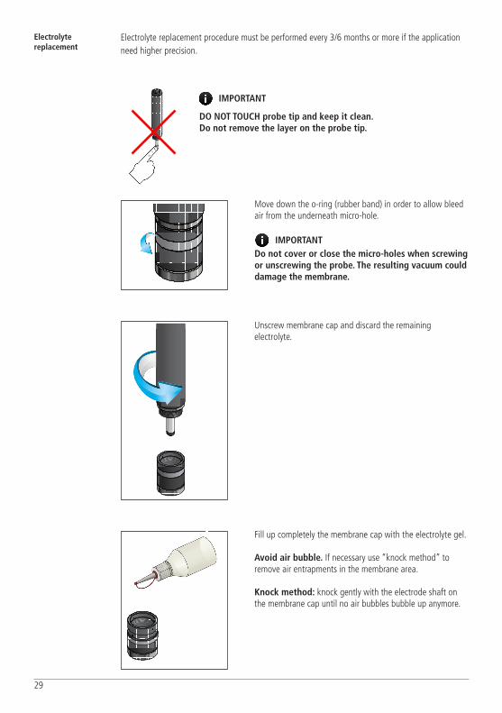
Electrolyte replacement
Electrolyte replacement procedure must be performed every 3/6 months or more if the application need higher precision.
IMPORTANT
DO NOT TOUCH probe tip and keep it clean.Do not remove the layer on the probe tip.
Progettato da: Controllato da: Data:
Edizione Foglio/Esploso_ECL1
Massimo_F Massimo_F 13/06/2013
00
Toll. Gen.±0.05
Peso Lordo: Peso Netto:
Materiale:
1 1
Unscrew membrane cap and discard the remaining electrolyte.
Progettato da: Controllato da: Data:
Edizione Foglio/Esploso_ECL1
Massimo_F Massimo_F 13/06/2013
00
Toll. Gen.±0.05
Peso Lordo: Peso Netto:
Materiale:
1 1
Fill up completely the membrane cap with the electrolyte gel.
Avoid air bubble. If necessary use “knock method” to remove air entrapments in the membrane area.
Knock method: knock gently with the electrode shaft on the membrane cap until no air bubbles bubble up anymore.
Progettato da: Controllato da: Data:
Edizione Foglio/
Assieme_ECL1_GuarnizioneOK
Massimo_F Massimo_F 13/06/2013
00
Toll. Gen.±0.05
Peso Lordo: Peso Netto:
Materiale:
1 1
Do not cover or close the micro-holes when screwing or unscrewing the probe. The resulting vacuum could damage the membrane.
IMPORTANT
Move down the o-ring (rubber band) in order to allow bleed air from the underneath micro-hole.
Progettato da: Controllato da: Data:
Edizione Foglio/Esploso_ECL1
Massimo_F Massimo_F 13/06/2013
00
Toll. Gen.±0.05
Peso Lordo: Peso Netto:
Materiale:
1 1
30
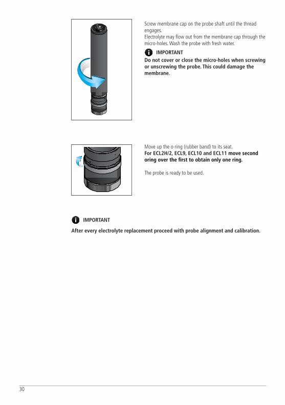
Screw membrane cap on the probe shaft until the thread engages.Electrolyte may flow out from the membrane cap through the micro-holes. Wash the probe with fresh water.
Progettato da: Controllato da: Data:
Edizione Foglio/Assieme_ECL1
Massimo_F Massimo_F 13/06/2013
00
Toll. Gen.±0.05
Peso Lordo: Peso Netto:
Materiale:
1 1
Do not cover or close the micro-holes when screwing or unscrewing the probe. This could damage the membrane.
IMPORTANT
Move up the o-ring (rubber band) to its seat. For ECL2H/2, ECL9, ECL10 and ECL11 move second oring over the first to obtain only one ring.
The probe is ready to be used.
After every electrolyte replacement proceed with probe alignment and calibration.
IMPORTANT
Progettato da: Controllato da: Data:
Edizione Foglio/Esploso_ECL1
Massimo_F Massimo_F 13/06/2013
00
Toll. Gen.±0.05
Peso Lordo: Peso Netto:
Materiale:
1 1

31
Maintenance schedule
DANGERMAINTENANCE SCHEDULEIn order to ensure the requirements of potable drinking water treated and the maintenance of the improvements as declared by the manufacturer, this equipment must be checked at least once a week.
DANGER OPERATOR PROTECTIONUse safety equipment according to the company regulations.Use this safety equipment within the work area during installation, service and when handling chemicals:
• protective mask• unpowdered nitrile gloves• safety goggles• further security device, if necessary.
DANGERPOWER SUPPLY DISCONNECTIONAlways disconnect power to the motor before you perform any installation or maintenance tasks. Failure to disconnect power will result in serious physical injury.
DANGER AUTHORIZED AND QUALIFIED PERSONNEL
Installation and maintenance tasks should be carried out by AUTHORIZED AND QUALIFIED PERSONNEL only in accordance with local regulations.
Use original spare parts.
INTERVAL MAINTENANCE INSPECTIONS REFERENCE
Weekly Control probe reading using a DPD1/DPD4 or colorimetric method.
Probe calibration procedure
Monthly Check probe integrity Cleaning procedure
Monthly Check electrical wiring -
Every 3/6 months
Replace electrolyte solution into membrane cap.Control membrane cap integrity.
Electrolyte replacement procedure
Yearly Replace membrane cap. Membrane cap replacement procedure
Shorten the inspection intervals appropriately if the chemical is abrasive or corrosive.
Maintenance inspection
MAINTENANCE
IMPORTANT

32
TROUBLESHOOTING
PROBLEM CAUSES SOLUTIONS
Probe cannot calibrated / deviation between measuring value and DPD result
Run-in time too short Repeat calibration
Membrane cracked / damaged Replace membrane cap
Interfering substances in the measuring water
Examine the measuring water for interfering substances and remedy, if necessary contact supplier
Air entrapments Knock gently with the electrode shaft on the membrane cap until no air bubbles bubble up anymore (“knock method”)
Short-circuit / damage in the signal leads Locate and eliminate short-circuit / defect, if necessary change the measuring cable
Air bubbles on the outside of the membrane
Increase the flow rate temporary, if necessary check installation and revise it
Distance between working electrode and membrane cap
Screw the membrane cap tightly onto the shaft
Deposits on membrane cap Carefully remove deposits with a soft brush or replace the membrane cap.
No electrolyte in the membrane cap Fill membrane cap with electrolyte
DPD-/titration chemicals spent Use new DPD-/titration chemicals, repeat calibration
Only valid for peracetic acid:improper method of titration
Repeat titration with an appropriate method (with a minimal titration volume)
Measuring signal is not stable Membrane cracked / damaged Replace membrane cap
Air bubbles in the electrolyte Empty out the membrane cap and refill it carefully with new electrolyte avoiding bubbles
Air bubbles on the outside of the membrane
Increase the flow rate temporary, if necessary check installation and revise it
Air entrapments Knock gently with the electrode shaft on the membrane cap until no air bubbles bubble up anymore (“knock method”)
Pressure fluctuations in the measuring water
Check and revise installation

33
PRODUCT SERVICE REPAIR FORM
SENDERCompany name ............................................................................................................................................ Address ................................................................................................................................................Phone no. ................................................................................................................................................Contact person.............................................................................................................................................
PRODUCT TYPE (see product label)DEVICE CODE .............................................................................................................................................. S/N (serial number).......................................................................................................................................
DESCRIPTION OF PROBLEM
MECHANICALWear parts .................................................................................................................................Brekage/other damages .............................................................................................................Corrosion ...................................................................................................................................Other .........................................................................................................................................
ELECTRICALConnections, connector, cables ...................................................................................................Other .........................................................................................................................................
NOT OR INADEQUATE FUNCTION/OTHER ................................................................................................................................................. ................................................................................................................................................. .................................................................................................................................................
MOD 7.5 B1 Q Ed. 1 - rev. 0 21/02/2012
OPERATING CONDITIONS
Location/installation description .................................................................................................................. ...................................................................................................................................................................Chemical ................................................................................................................................................Start-up (date) ............................................ Running time (approx. hours) ....................................................
REMOVE ALL THE LIQUID AND DRY IT BEFORE PACKAGING IN ITS ORIGINAL BOX.
I declare that the product is free of any hazardous chemical.
Signature of the compiler Company stamp
ENCLOSE THE PRESENT FORM TO THE DELIVERY NOTE
DATE ............................................

34

35

36