Embed Size (px)
Citation preview

1
A C O R B AT T E R Y P O W E R E D
H A N D S - F R E E F L O O R M O U N T E D WA S H S TAT I O N S
Operating Manual for Two-Person Hands-Free Floor Mounted Wash StationsAC Models 54FAL and 54FAL-0.5
Battery Models 54FBL and 54FBL-0.5
Columbia does not recommend use with harsh chemicals.NSF/ANSI Standard 2 - Food Equipment and NSF/ANSI 372 low-lead.

2COLUMBIA SPECIFICATIONS
1622 Browning Irvine, CA 92606-4809 Phone: 949.474.0777 Toll Free: 800.626.2117 Fax: 949.474.1191 www.columbiasinks.com email: [email protected]
©2018 Columbia Products
A C O R B AT T E R Y P O W E R E D
H A N D S - F R E E F L O O R M O U N T E D WA S H S TAT I O N S
Tools Required Tape Measure
Adjustable Wrench
Drill Motor and Drill Bits
Pipe Wrench
Level
Safety Glasses
Screw Drivers: 1 Phillips & 1 Standard
Pencil
Socket Wrench
Parts List (1) Floor mount wash station
(1) Leg assembly set
(4) Washers and nuts for connection sink to leg assembly set
(2) AC or Battery powered sensor faucet assembly
(2) Mixing check valve
(1) Strainer assembly with basket
Installation InstructionsStep 1
1. 2 and 3-Person models require leg assembly.
2. Place wash station sink on leg assembly and secure with hardware (provided).
3. Establish sink location.
4. Mark the floor where the four holes are at the base as shown in illustration A.
5. Drill holes as required for mounting hardware. (Hardware not included).
Step 2
1. Install strainer assembly.
2. Install faucets to the sink following the instructions provided with sensor unit.
3. Attach supply tube with elbow to back of faucet.
4. Install mixing check valve and compression fitting to control box of each sensor faucet.
Step 3
1. Secure wash station to floor.
2. Connect waste line to strainer assembly (s).
3. Mount sensor control boxes at desired location on wall.
4. Connect power line from sensor to control box.
5. Attach supply tube from faucet to control box.
6. Connect hot and cold water from the source to mixing check valve (s).
7. Remove aerator from the spout assemblies and flush water system. (see step 7 sensor installation instructions)
8. Check connections for leaks.
9. Replace aerator onto the spout (s).
Step 4
1. Seal gap between bowl and leg assembly as shown in illustration B.
2. We recommend sealing top of backsplash to wall if applicable as shown in illustration C.
Illustration A
Illustration B
Illustration C

3COLUMBIA SPECIFICATIONS
1622 Browning Irvine, CA 92606-4809 Phone: 949.474.0777 Toll Free: 800.626.2117 Fax: 949.474.1191 www.columbiasinks.com email: [email protected]
©2018 Columbia Products
A C O R B AT T E R Y P O W E R E D
H A N D S - F R E E F L O O R M O U N T E D WA S H S TAT I O N S
1.5” (38mm)
20” (508mm)2” (51mm)
54 Floor
10.25”(267 mm)
40” (1017mm)20” (508mm)
37” (940mm)
20” (508mm)
11”(305mm)
18”(610mm)
11”(305mm)
20”(508mm)
2” drain hole
16.5”(407mm)
10”(254mm)
8” (203mm)
1.5” (38mm)
2” (51mm)
1.5” (38mm)
6.75” (171mm)
10” (254mm).875” (22mm)
dia. holes (2)
35” (889mm)suggested floor to rim
height
27” (686mm)
45º
2.875” (73.02mm)
.75” (20mm)
7.5” (191mm)
.5” R(12.7mm)
.5” R (12.7mm)
Side
Top
Floor Mounting Detail
.5” dia.Floor
MountingHoles
10.5” onCenter
1.5” LegThickness
.75” From Edge of Leg to First Hole
Hole Configurations
Front
33.8125” (858.8mm)

OPERATION & MAINTENANCE MANUAL6700C Series Faucet
5055 Forsyth Commerce Rd, Ste 124, Orlando, FL 32807Phone (800) 922-9883 | Fax (866) 670-5580
www.hydrotekintl.com
Sensor Faucets and Flush Valves

ISO 9001 Certified
6700C SeriesU.S. Patent 6192530B1
AC or Battery Powered Sensor Operated Faucet
The 6700C Series faucet is a piston operated, wall mounted sensor faucet that provides a vandal resistant, no touch solution that promotes better hygiene and energy savings.
Using Hydrotek’s patented gooseneck design, the 6700C Series faucet is ideal in clinics, hospitals, and manufacturing facilities for scrub stations.
• ADA Compliant. Meets all barrier free codes• Conserves water and energy• Easily installed in new or retrofit applications• Competitively priced for today’s commercial market• Promotes cleanliness & hygiene• Proven Hydrotek craftsmanship and reliability
Available in: D Low Lead, AC Powered (H-6700C-LR) D Low Lead, Battery Powered (HB-6700C-LR) D Low Lead, AC Powered with DC Backup (HB-6700C-LRDC)
• ACCU-SENSE adjustable sensor eyes.• Chrome plated, solid brass construction.• Wall mountable, waterproof control box with
armored, vandal resistant control and power cables.
• Preset/adjustable sensor range of 6” - 30” for various installation requirements.
• Standard automatic time-out feature. Preset at 30 seconds, but adjustable to 10, 30, or 60 seconds. Prevents accidental sink overflow.
• Shut-off delay is adjustable from 1 (preset) to 8 seconds.
• Single-hole, wall/splash mounting• Includes in-line filter with clean-out trap to
reduce maintenance costs.• Standard 6” gooseneck spout and 2.0 GPM or 0.5
GPM Laminar flow control.
• All parts are field-replaceable to ensure quick and easy repair.
• Same faucet-field switchable to AC or battery powered.
• AC with DC backup models automatically switch to batteries during a power outage.
• Slow closing, piston-operated solenoid valve provides reliable and smooth operation without water hammer.
• Superior VSI silicone elastomer piston seals are unaffected by chlorine, chloromines, or ammonia.
• Control module allows a unique self-check of all electrical components.
• No-touch system enhances hygiene in medical, institutional, food service industries, etc.
Features:
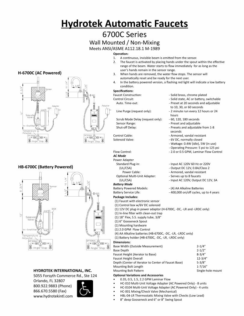
Hydrotek Automatic Faucets6700C Series
Wall Mounted / Non-MixingMeets ANSI/ASME A112.18.1 M-1989
Operation:1. A continuous, invisible beam is emitted from the sensor.2. The faucet is activated by placing hands under the spout within the effective
range of the beam. Water starts to flow immediately for as long as the user’s hands remain in the sensor range.
3. When hands are removed, the water flow stops. The sensor will automatically reset and be ready for the next user.
4. In the battery powered version, a flashing red light will indicate a low battery condition.
Specifications:Faucet Construction: - Solid brass, chrome platedControl Circuit: - Solid state, AC or battery, switchable Auto. Time-out: - Preset at 20 seconds and adjustable to 10, 30, or 60 seconds Line Purge (request only): - 2 minute run every 12 hours or 24 hours Scrub Mode Delay (request only): - 60, 120, 180 seconds Sensor Range: - Preset and adjustable Shut-off Delay: - Presets and adjustable from 1-8 secondsControl Cable: - Armored, vandal resistantSolenoid Valve: - 6V DC, normally closed - Wattage: 0.4W (idle), 5W (in use) - Operating Pressure: 5 psi to 125 psiFlow Control: - 2.0 or 0.5 GPM, Laminar Flow ControlACModePower Adapter Standard Plug-in: - Input AC 120V 60 Hz or 220V (UL/CSA) - Output DC 12V, 0.8A/Class 2 Power Cable: - Armored, vandal resistant Optional Multi-Unit Adapter: - Serves up to 8 faucets (UL/CSA) - Input AC 120V, Output DC 12V, 3ABatteryModeBattery Powered Models: - (4) AA Alkaline BatteriesBattery Service Life: - 400,000 on/off cycles, up to 4 yearsPackage Includes: (1) Faucet with electronic sensor (1) Control box w/6V DC solenoid (1) 12V DC plug-in power adaptor (H-6700C, -DC, -LR and -LRDC only) (1) In-line filter with clean-out trap (1) 18” Flex, S.S. supply tube, 3/8” (1) 6” Gooseneck Spout (1) Mounting hardware (1) 2.0 GPM Flow Control (4) AA Alkaline batteries (HB-6700C, -DC, -LR, -LRDC only) (1) Battery holder (HB-6700C, -DC, -LR, -LRDC only)Dimensions:Base Width (Outside Measurement) 2-1/4”Base Depth 2-1/2”Faucet Height (Aerator to Base) 8-3/4”Faucet Height Overall 12-3/4”Depth (Center of Aerator to Center of Faucet Base) 5-3/8”Mounting Bolt Length 1-7/16”Mounting Bolt Pattern Single-hole mountOptional Variations and Accessories• 0.35, 0.5, 1.5, 2.2 GPM Laminar Flow• HC-010 Multi-Unit Voltage Adapter (AC Powered Only) - 8 units• HC-0104 Multi-Unit Voltage Adapter (AC Powered Only) - 4 units• HC-001 Mixing/Check Valve (Mechanical)• HBL-04-LR Thermostatic Mixing Valve with Checks (Low Lead)• 8” deep Gooseneck and 6” or 8” Swing Spout
H-6700C (AC Powered)
HB-6700C (Battery Powered)
HYDROTEK INTERNATIONAL, INC.5055 Forsyth Commerce Rd., Ste 124Orlando, FL 32807800.922.9883 (Phone)866.670.5580 (Fax)www.hydrotekintl.com

6700C SeriesDC Powered Sensor Operated Mixing Faucet
Installation InstructionsISO 9001 Certified
6700C SeriesSensor Operated Faucet
Installation Instructions
HYDROTEK INTERNATIONAL, INC.5055 Forsyth Commerce Rd., Ste 124Orlando, FL 32807800.922.9883 (Phone)866.670.5580 (Fax)www.hydrotekintl.com
1. Flow Control Device2. Gooseneck Spout3. Spout Nut4. Split Washer5. Body6. LED Sensor Cover7. Supply Rod8. O-Ring9. Washer10. Mounting Nut
11. 90 Degree Elbow12. Supply Tube13. Compression Fitting14. Solenoid Valve15. In-Line Filter16. Nylon Washer17. Sensor Eye Cable18. Control Box19. Power Adapter
Parts:
1. Prior to installation, thoroughly flush all water lines and replace stop washers, if required.
2. To ensure proper operation, “DRY TEST” the faucet by plugging the Sensor Eye Cable (17) into the matching connector on the PC board inside of the Control Box (18). a. AC Powered: Connect the Power Adapter (19) to the PC board
inside of the Control Box (18), then plug the Power Adapter into a 120 V AC wall outlet. Place your hand in front of the sensor eye and listen for a clicking sound. If there is no clicking sound, call the factory.
b. Battery Powered: Properly install new batteries into the battery holder and ensure the battery holder is connected to the PC board. Place your hand in front of the sensor eye and listen for a clicking sound. If there is no clicking sound, call the factory.
3. After a successful “DRY TEST”, unplug the Sensor Eye Cable (17) and Power Adapter (19) or battery holder from the PC board.
4. Loosen Flow Control Device (1) and assemble the Gooseneck Spout (2) using the Split Washers (4) and Spout Nut (3). Mount the Gooseneck Spout (2) onto the Body (5). Feed the Sensor Eye Cable (17) through the sink wall and tighten the faucet onto the sink using the O-Ring (8), Washer (9), and Mounting Nut (10). Attach the 90-Degree Elbow (11) to the Supply Rod (7).
USE TEFLON TAPE ONLY, NO PIPE DOPE5. Reconnect the Sensor Eye Cable (17) and Power Adapter (19)
connections described in STEP #2, making sure the cables are seating in the Control Box (18) housing properly.
6. Attach the Compression Fitting (13) to the Solenoid Valve (14) and connect it to the Elbow (11) usingn the Supply Tube (12). Insert the Nylon Washer (16) into the swivel nut located on the In-Line Filter (15). a. Pre-tempered or cold water only: Use a union fitting (not
supplied) to connect the supply line (not supplied) from the supply stop to the In-Line Filter (15).
b. Tempered water: Attach an optional Hydrotek HC-001 or HC-003 mixing valveto the In-Line Filter (15). Connect the supply lines (not supplied) to the mixing valve.
7. Turn on water and check for leaks. Plug the Power Adapter (19) into a 120V AC outlet (for AC Powered). Push the reset button on the PC Board. Reinstall the cover for the Control Box (18) and tighten screws to ensure water resistance. Place hands in front of the sensor eye to activate water flow. Remove hands and the water should stop. If not, refer to the troubleshooting guide or call the factory.
8. Periodically clean the filter element located inside the In-Line Filter (15).
9. For minor adjustments, refer to the instructions located inside the cover of the Control Box (18).
10. IMPORTANT: The stop valve should never be opened to the point where the water flow exceeds the flow capability of the fixture. The fixture must be able to accommodate the continuous water flow from the faucet in the event of a failure. Should the fixture overflow due to water exceeding the capability of the fixture and/or the drain pipe, Hydrotek will not be responsible for any damages.
6700C SeriesSensor Operated Mixing Faucet
Troubleshooting Guide
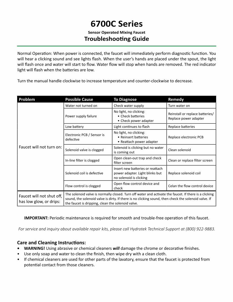
Normal Operation: When power is connected, the faucet will immediately perform diagnostic function. You will hear a clicking sound and see lights flash. When the user’s hands are placed under the spout, the light will flash once and water will start to flow. Water flow will stop when hands are removed. The red indicator light will flash when the batteries are low.
Turn the manual handle clockwise to increase temperature and counter-clockwise to decrease.
Problem Possible Cause To Diagnose Remedy
Faucet will not turn on:
Water not turned on Check water supply Turn water on
Power supply failureNo light, no clicking:
• Check batteries• Check power adapter
Reinstall or replace batteries/Replace power adapter
Low battery Light continues to flash Replace batteries
Electronic PCB / Sensor is defective
No light, no clicking:• Reinsert batteries• Reattach power adapter
Replace electronic PCB
Solenoid valve is clogged Solenoid is clicking but no water is coming out Clean solenoid
In-line filter is clogged Open clean-out trap and check filter screen Clean or replace filter screen
Solenoid coil is defectiveInsert new batteries or reattach power adapter. Light blinks but no solenoid is clicking
Replace solenoid coil
Flow control is clogged Open flow control device and check Celan the flow control device
Faucet will not shut off, has low glow, or drips:
The solenoid valve is normally closed. Turn off water and activate the faucet. If there is a clicking sound, the solenoid valve is dirty. If there is no clicking sound, then check the solenoid valve. If the faucet is dripping, clean the solenoid valve.
IMPORTANT: Periodic maintenance is required for smooth and trouble-free operation of this faucet.
For service and inquiry about available repair kits, please call Hydrotek Technical Support at (800) 922-9883.
Care and Cleaning Instructions:• WARNING! Using abrasive or chemical cleaners will damage the chrome or decorative finishes. • Use only soap and water to clean the finish, then wipe dry with a clean cloth. • If chemical cleaners are used for other parts of the lavatory, ensure that the faucet is protected from
potential contact from those cleaners.