Embed Size (px)
Citation preview
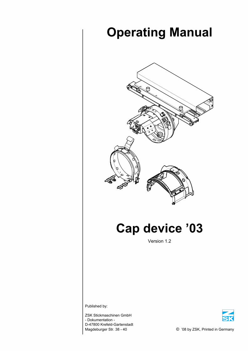
Operating Manual
Cap device ’03Version 1.2
Published by:
ZSK Stickmaschinen GmbH- Dokumentation -D-47800 Krefeld-GartenstadtMagdeburger Str. 38 - 40 © ’08 by ZSK, Printed in Germany

Subject to change © ‘08 by ZSK, Printed in Germany
Contents
00783t12IVZ.fm 21.4.08/Ch,Kx
Contents
Basic principles 1 - 1
Baseball caps . . . . . . . . . . . . . . . . . . . . . . . . . . . . . . . . . . . . . . . . . . 1 - 1
a) Five-panel cap. . . . . . . . . . . . . . . . . . . . . . . . . . . . . . . . . . . 1 - 3
b) Six-panel cap. . . . . . . . . . . . . . . . . . . . . . . . . . . . . . . . . . . . 1 - 4
Other caps . . . . . . . . . . . . . . . . . . . . . . . . . . . . . . . . . . . . . . . . . . . . 1 - 5
Overview 2 - 1
General view with cap frame . . . . . . . . . . . . . . . . . . . . . . . . . . . . . . 2 - 1
Clamping aid for cap frames. . . . . . . . . . . . . . . . . . . . . . . . . . . . . . . 2 - 1
Installation 3 - 1
Converting machine for cap embroidery. . . . . . . . . . . . . . . . . . . . . . 3 - 1
Preparations. . . . . . . . . . . . . . . . . . . . . . . . . . . . . . . . . . . . . . . . . 3 - 1
JAF/JAFA series . . . . . . . . . . . . . . . . . . . . . . . . . . . . . . . . . . . 3 - 1
Installing cap drive, determining center position . . . . . . . . . . . . . 3 - 2
Installing cap drive, determining front position . . . . . . . . . . . . . . . 3 - 2
JAF/JAFA series . . . . . . . . . . . . . . . . . . . . . . . . . . . . . . . . . . . 3 - 2
SPRINT 2/SPRINT 4 . . . . . . . . . . . . . . . . . . . . . . . . . . . . . . . . 3 - 3
Installing cap drive. . . . . . . . . . . . . . . . . . . . . . . . . . . . . . . . . . 3 - 4
Dismantling cap drive . . . . . . . . . . . . . . . . . . . . . . . . . . . . . . . 3 - 7
Exchanging stitch plate inserts. . . . . . . . . . . . . . . . . . . . . . . . . . . 3 - 8
Different stitch plate inserts . . . . . . . . . . . . . . . . . . . . . . . . . . . 3 - 8
Removing stitch plate insert . . . . . . . . . . . . . . . . . . . . . . . . . . 3 - 9
Installing stitch plate insert . . . . . . . . . . . . . . . . . . . . . . . . . . . 3 - 9
Cap device ’03 – Version 1.2 C - 1
Contents
C - 2
Clamping the cap 4 - 1
Choice of caps for 135/360 mm cap frame. . . . . . . . . . . . . . . . . . . . 4 - 1
clamping aid . . . . . . . . . . . . . . . . . . . . . . . . . . . . . . . . . . . . . . . . . . . 4 - 2
Preparing clamping aid . . . . . . . . . . . . . . . . . . . . . . . . . . . . . . 4 - 2
Pivoting clamping aid . . . . . . . . . . . . . . . . . . . . . . . . . . . . . . . 4 - 3
Cap frame with guard . . . . . . . . . . . . . . . . . . . . . . . . . . . . . . . 4 - 3
360 mm cap frame . . . . . . . . . . . . . . . . . . . . . . . . . . . . . . . . . . . . . . 4 - 4
Clamping the cap . . . . . . . . . . . . . . . . . . . . . . . . . . . . . . . . . . 4 - 5
Fastening clips . . . . . . . . . . . . . . . . . . . . . . . . . . . . . . . . . . . . 4 - 9
Pulling cap frame out of clamping aid . . . . . . . . . . . . . . . . . . 4 - 10
Cap frame without guard . . . . . . . . . . . . . . . . . . . . . . . . . . . . 4 - 10
Cap frame with guard . . . . . . . . . . . . . . . . . . . . . . . . . . . . . . 4 - 10
135 mm cap frame . . . . . . . . . . . . . . . . . . . . . . . . . . . . . . . . . . . . . 4 - 11
Size of hinged window. . . . . . . . . . . . . . . . . . . . . . . . . . . . . . 4 - 11
Mounting the frame . . . . . . . . . . . . . . . . . . . . . . . . . . . . . . . . . . 4 - 12
Adjust the size of the rest. . . . . . . . . . . . . . . . . . . . . . . . . . . . 4 - 12
Adjusting window size individually. . . . . . . . . . . . . . . . . . . . . 4 - 12
Clamping the cap . . . . . . . . . . . . . . . . . . . . . . . . . . . . . . . . . 4 - 13
Cap frame without guard . . . . . . . . . . . . . . . . . . . . . . . . . . . . 4 - 14
Cap frame with guard . . . . . . . . . . . . . . . . . . . . . . . . . . . . . . 4 - 14
Inserting cap frame 5 - 1
Preparing for embroidering . . . . . . . . . . . . . . . . . . . . . . . . . . . . . . . . 5 - 2
Selecting the needle. . . . . . . . . . . . . . . . . . . . . . . . . . . . . . . . . . . 5 - 2
Loading a design - JAF/JAFA series . . . . . . . . . . . . . . . . . . . . . . 5 - 2
Checking center position of cap drive . . . . . . . . . . . . . . . . . . . 5 - 2
Loading design - SPRINT 2/SPRINT 4 . . . . . . . . . . . . . . . . . . . . 5 - 3
Checking center position of cap drive . . . . . . . . . . . . . . . . . . . 5 - 3
Notes on punching 6 - 1
Choice of design . . . . . . . . . . . . . . . . . . . . . . . . . . . . . . . . . . . . . . . . 6 - 1
Cap device ’03 – Version 1.2 00783t12IVZ.fm 21.4.08/Ch,Kx
Contents
00783t12IVZ.fm 21.4.08/Ch,Kx
Cap designs in general . . . . . . . . . . . . . . . . . . . . . . . . . . . . . . . . . . . 6 - 2
Designs for six-panel caps . . . . . . . . . . . . . . . . . . . . . . . . . . . . . . . . 6 - 4
Troubleshooting 7 - 1
Index I - 1
Cap device ’03 – Version 1.2 C - 3

Contents
C - 4
Cap device ’03 – Version 1.2 00783t12IVZ.fm 21.4.08/Ch,Kx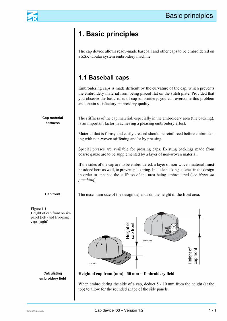
Basic principles
1. Basic principles
The cap device allows ready-made baseball and other caps to be embroidered ona ZSK tubular system embroidery machine.
1.1 Baseball capsEmbroidering caps is made difficult by the curvature of the cap, which preventsthe embroidery material from being placed flat on the stitch plate. Provided thatyou observe the basic rules of cap embroidery, you can overcome this problemand obtain satisfactory embroidery quality.
Cap material stiffness
The stiffness of the cap material, especially in the embroidery area (the backing),is an important factor in achieving a pleasing embroidery effect.
Material that is flimsy and easily creased should be reinforced before embroider-ing with non-woven stiffening and/or by pressing.
Special presses are available for pressing caps. Existing backings made fromcoarse gauze are to be supplemented by a layer of non-woven material.
If the sides of the cap are to be embroidered, a layer of non-woven material mustbe added here as well, to prevent puckering. Include backing stitches in the designin order to enhance the stiffness of the area being embroidered (see Notes onpunching).
Cap front The maximum size of the design depends on the height of the front area.
Figure 1.1: Height of cap front on six-panel (left) and five-panel caps (right)
Calculatingembroidery field
Height of cap front (mm) - 30 mm = Embroidery field
When embroidering the side of a cap, deduct 5 - 10 mm from the height (at thetop) to allow for the rounded shape of the side panels.
00001002
00001003
Hei
ght o
fca
p fro
nt
Hei
ght o
fca
p fro
nt
00783112.fm 21.4.08/Kx Cap device ’03 – Version 1.2 1 - 1
Basic principles
Clamping Exercise great care when clamping the caps in order to avoid creases and bulges,and to prevent misalignment when embroidering.
NOTE As a general rule with a 135 mm frame, attach non-woven material be-hind the area being embroidered before clamping the cap. With a360 mm frame, non-woven material is to be attached behind the sideof the cap if this area is being embroidered.
Clamp the cap by working gradually from left to right (360 mm capframe) or from right to left (135 mm cap frame) as appropriate.
Needle andembroidery speed
Select a suitable needle and embroider with a moderate speed. Observe the fol-lowing basic rule: the stiffer the embroidery area, the stronger the needle and thelower the embroidery speed.
Design Use designs created specifically for caps or adapt other existing designs accord-ingly. Also observe the Notes on punching at the end of this manual.
Cap shape Caps are available in a wide variety of different shapes. The ZSK cap devices aredesigned for the following two basic shapes:
1 - 2 Cap device ’03 – Version 1.2 00783112.fm 21.4.08/Kx
Basic principles
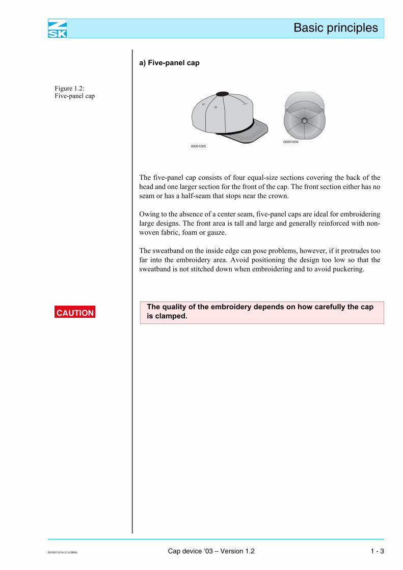
a) Five-panel cap
Figure 1.2: Five-panel cap
The five-panel cap consists of four equal-size sections covering the back of thehead and one larger section for the front of the cap. The front section either has noseam or has a half-seam that stops near the crown.
Owing to the absence of a center seam, five-panel caps are ideal for embroideringlarge designs. The front area is tall and large and generally reinforced with non-woven fabric, foam or gauze.
The sweatband on the inside edge can pose problems, however, if it protrudes toofar into the embroidery area. Avoid positioning the design too low so that thesweatband is not stitched down when embroidering and to avoid puckering.
0000100500001004
The quality of the embroidery depends on how carefully the capis clamped.
00783112.fm 21.4.08/Kx Cap device ’03 – Version 1.2 1 - 3
Basic principles
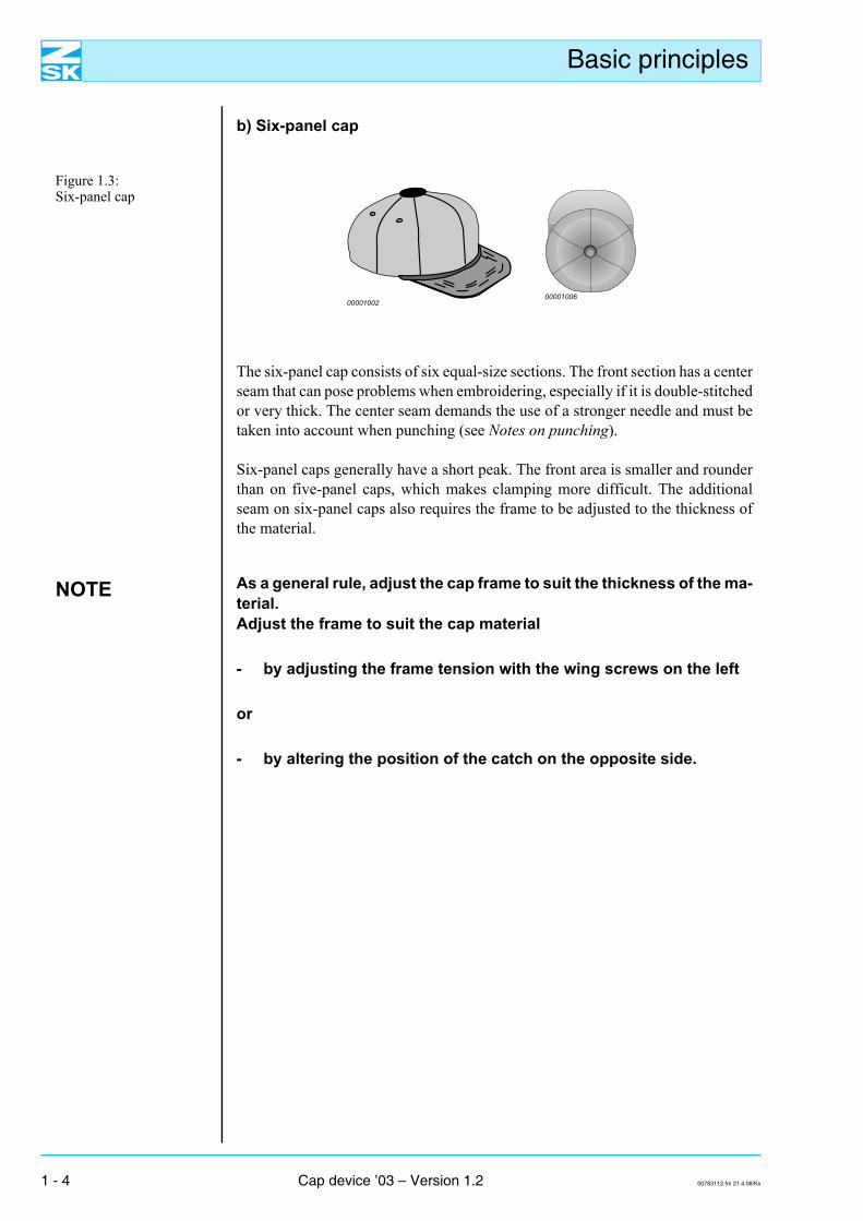
b) Six-panel cap
Figure 1.3: Six-panel cap
The six-panel cap consists of six equal-size sections. The front section has a centerseam that can pose problems when embroidering, especially if it is double-stitchedor very thick. The center seam demands the use of a stronger needle and must betaken into account when punching (see Notes on punching).
Six-panel caps generally have a short peak. The front area is smaller and rounderthan on five-panel caps, which makes clamping more difficult. The additionalseam on six-panel caps also requires the frame to be adjusted to the thickness ofthe material.
NOTE As a general rule, adjust the cap frame to suit the thickness of the ma-terial.Adjust the frame to suit the cap material
- by adjusting the frame tension with the wing screws on the left
or
- by altering the position of the catch on the opposite side.
0000100600001002
1 - 4 Cap device ’03 – Version 1.2 00783112.fm 21.4.08/Kx
Basic principles
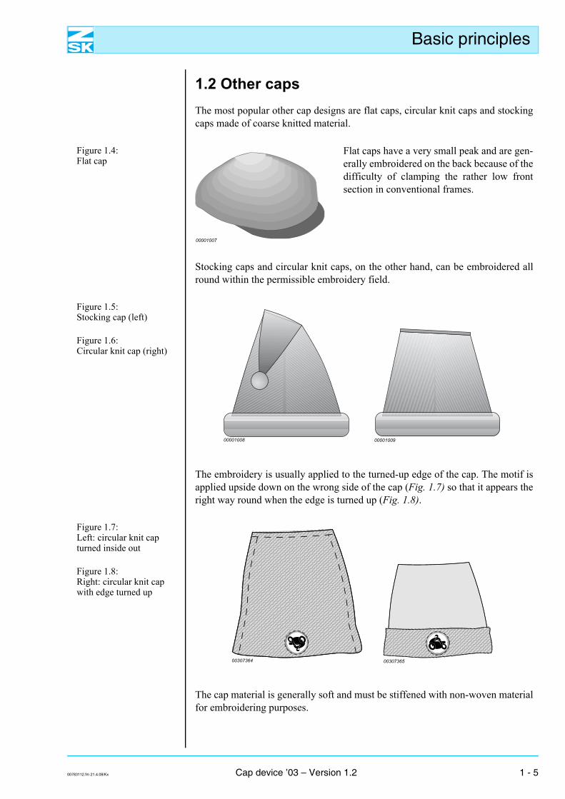
1.2 Other capsThe most popular other cap designs are flat caps, circular knit caps and stockingcaps made of coarse knitted material.
Figure 1.4: Flat cap
Flat caps have a very small peak and are gen-erally embroidered on the back because of thedifficulty of clamping the rather low frontsection in conventional frames.
Stocking caps and circular knit caps, on the other hand, can be embroidered allround within the permissible embroidery field.
Figure 1.5: Stocking cap (left)
Figure 1.6: Circular knit cap (right)
The embroidery is usually applied to the turned-up edge of the cap. The motif isapplied upside down on the wrong side of the cap (Fig. 1.7) so that it appears theright way round when the edge is turned up (Fig. 1.8).
Figure 1.7: Left: circular knit cap turned inside out
Figure 1.8: Right: circular knit cap with edge turned up
The cap material is generally soft and must be stiffened with non-woven materialfor embroidering purposes.
00001007
00001008 00001009
00307364 00307365
00783112.fm 21.4.08/Kx Cap device ’03 – Version 1.2 1 - 5

Basic principles
NOTE To hold caps that are not baseball caps firmly in place, make the fas-teners on the cap frame tighter than usual.
Use only the 135 mm frame to embroider these caps.
1 - 6 Cap device ’03 – Version 1.2 00783112.fm 21.4.08/Kx
Overview
2. Overview
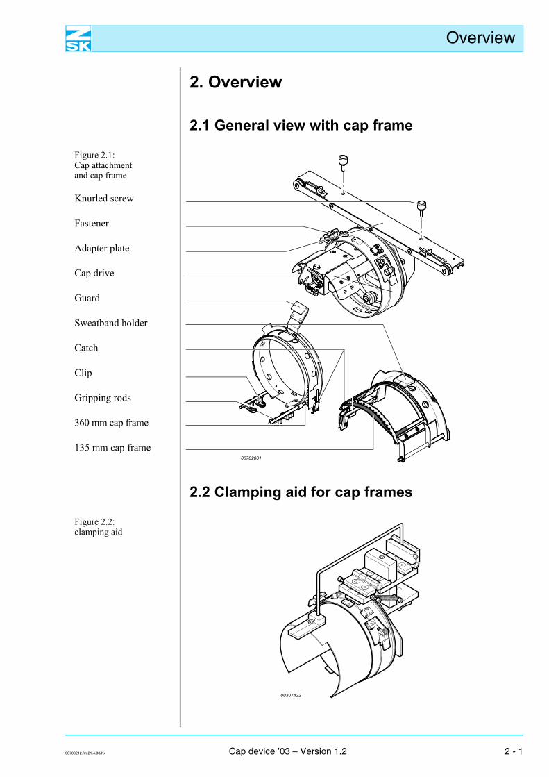
2.1 General view with cap frame
Figure 2.1: Cap attachmentand cap frame
Knurled screw
Fastener
Adapter plate
Cap drive
Guard
Sweatband holder
Catch
Clip
Gripping rods
360 mm cap frame
135 mm cap frame
2.2 Clamping aid for cap frames
Figure 2.2: clamping aid
00782001
00307432
00783212.fm 21.4.08/Kx Cap device ’03 – Version 1.2 2 - 1

Overview
2 - 2 Cap device ’03 – Version 1.2 00783212.fm 21.4.08/Kx
Installation
3. Installation
3.1 Converting machine for cap embroidery3.1.1 PreparationsThe cap device is installed with the machine set up for tubular system (cylinderarm) embroidery, that is to say: The work table has been lowered or dismantled.
JAF/JAFA series
It is essential to move the cord feet of any double roller cord andcord-loop embroidery devices that are installed to the parked po-sition (also see further information in the accompanying Opera-tor’s Guide).
If a needle that is equipped with a cord foot or a borer is activatedusing an incorrect setting at the control unit, damage may occurto the machine, cap devices and embroidery material.
NOTE The boring, sequin, double roller cord and cord-loop embroidery de-vices cannot be used when embroidering caps.
00783312.fm 21.4.08/Kx Cap device ’03 – Version 1.2 3 - 1
Installation
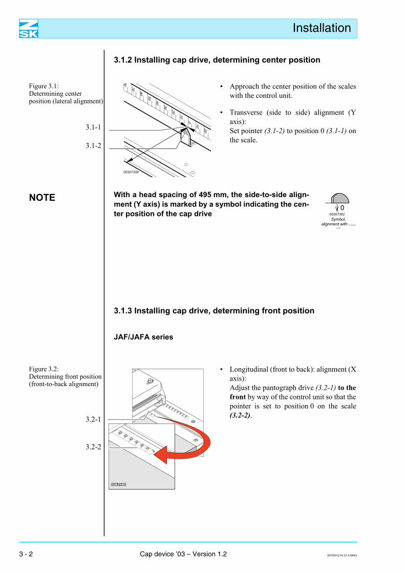
3.1.2 Installing cap drive, determining center position
Figure 3.1: Determining center position (lateral alignment)
3.1-1
3.1-2
• Approach the center position of the scaleswith the control unit.
• Transverse (side to side) alignment (Yaxis):Set pointer (3.1-2) to position 0 (3.1-1) onthe scale.
00307308
NOTE With a head spacing of 495 mm, the side-to-side align-ment (Y axis) is marked by a symbol indicating the cen-ter position of the cap drive
Symbol, alignment with 495 mm head
spacing
000307362
3.1.3 Installing cap drive, determining front position
JAF/JAFA series
Figure 3.2: Determining front position (front-to-back alignment)
3.2-1
3.2-2
• Longitudinal (front to back): alignment (Xaxis):Adjust the pantograph drive (3.2-1) to thefront by way of the control unit so that thepointer is set to position 0 on the scale(3.2-2).
00782010
3 - 2 Cap device ’03 – Version 1.2 00783312.fm 21.4.08/Kx
Installation
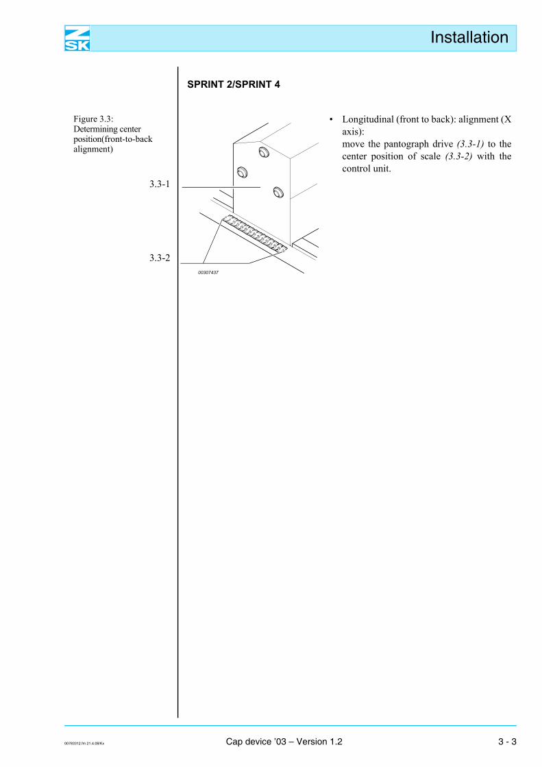
SPRINT 2/SPRINT 4
Figure 3.3: Determining center position(front-to-back alignment)
3.3-1
3.3-2
• Longitudinal (front to back): alignment (Xaxis): move the pantograph drive (3.3-1) to thecenter position of scale (3.3-2) with thecontrol unit.
05 10 15 20 25 30 35 40 45 50 55 60 65 70
00307437
00783312.fm 21.4.08/Kx Cap device ’03 – Version 1.2 3 - 3
Installation
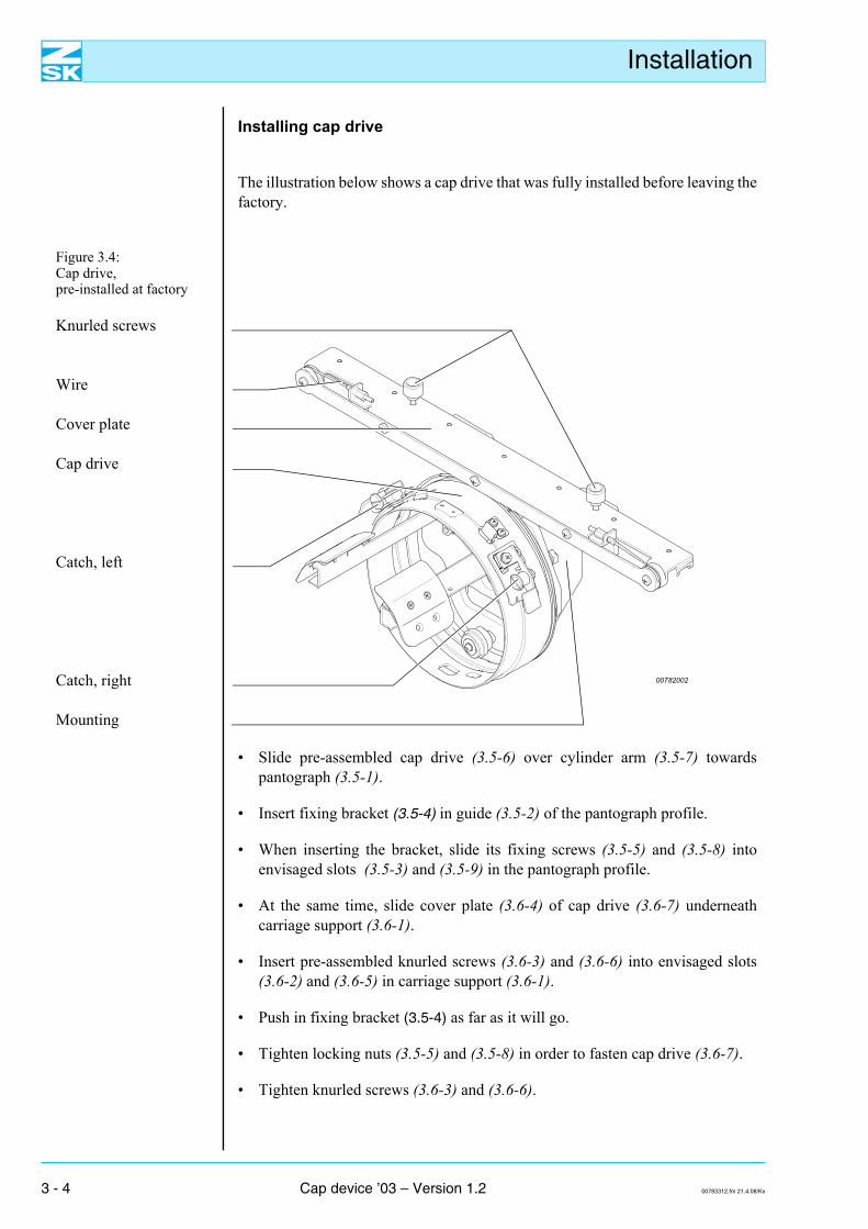
Installing cap drive
The illustration below shows a cap drive that was fully installed before leaving thefactory.
Figure 3.4: Cap drive,pre-installed at factory
Knurled screws
Wire
Cover plate
Cap drive
Catch, left
Catch, right
Mounting
00782002
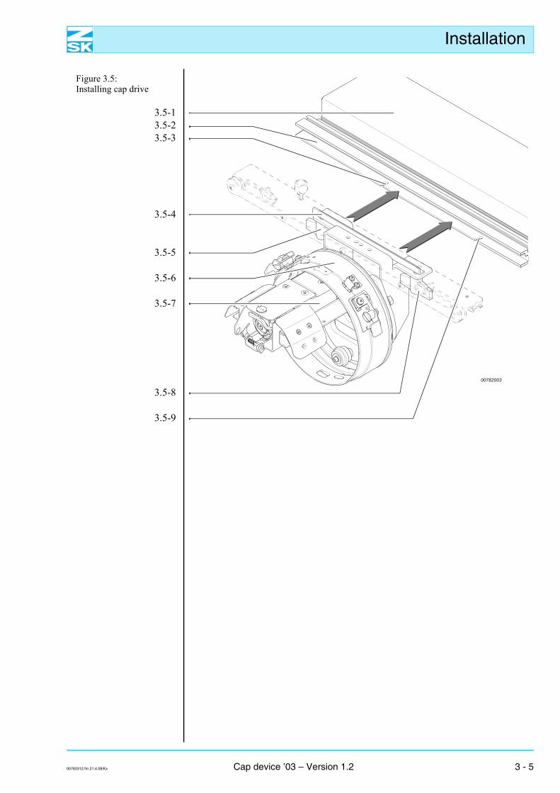
• Slide pre-assembled cap drive (3.5-6) over cylinder arm (3.5-7) towardspantograph (3.5-1).
• Insert fixing bracket (3.5-4) in guide (3.5-2) of the pantograph profile.
• When inserting the bracket, slide its fixing screws (3.5-5) and (3.5-8) intoenvisaged slots (3.5-3) and (3.5-9) in the pantograph profile.
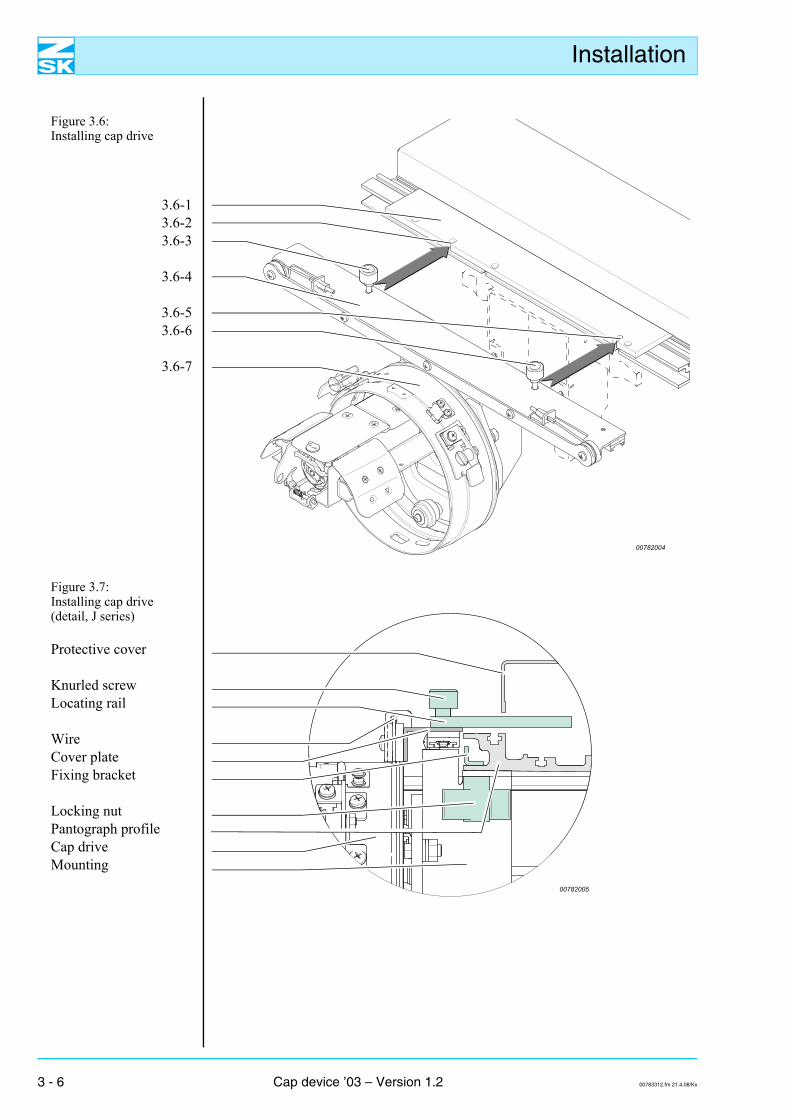
• At the same time, slide cover plate (3.6-4) of cap drive (3.6-7) underneathcarriage support (3.6-1).
• Insert pre-assembled knurled screws (3.6-3) and (3.6-6) into envisaged slots(3.6-2) and (3.6-5) in carriage support (3.6-1).
• Push in fixing bracket (3.5-4) as far as it will go.
• Tighten locking nuts (3.5-5) and (3.5-8) in order to fasten cap drive (3.6-7).
• Tighten knurled screws (3.6-3) and (3.6-6).
3 - 4 Cap device ’03 – Version 1.2 00783312.fm 21.4.08/Kx
Installation
Figure 3.5: Installing cap drive
3.5-13.5-23.5-3
3.5-4
3.5-5
3.5-6
3.5-7
3.5-8
3.5-9
00782003
00783312.fm 21.4.08/Kx Cap device ’03 – Version 1.2 3 - 5
Installation
Figure 3.6: Installing cap drive
3.6-13.6-23.6-3
3.6-4
3.6-53.6-6
3.6-7
Figure 3.7: Installing cap drive (detail, J series)
Protective cover
Knurled screwLocating rail
WireCover plateFixing bracket
Locking nutPantograph profileCap driveMounting
00782004
00782005
3 - 6 Cap device ’03 – Version 1.2 00783312.fm 21.4.08/Kx
Installation
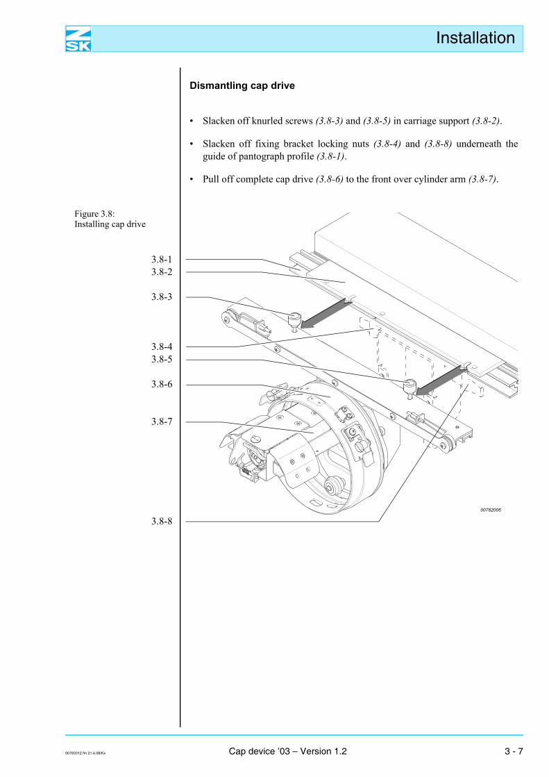
Dismantling cap drive
• Slacken off knurled screws (3.8-3) and (3.8-5) in carriage support (3.8-2).
• Slacken off fixing bracket locking nuts (3.8-4) and (3.8-8) underneath theguide of pantograph profile (3.8-1).
• Pull off complete cap drive (3.8-6) to the front over cylinder arm (3.8-7).
Figure 3.8: Installing cap drive
3.8-13.8-2
3.8-3
3.8-43.8-5
3.8-6
3.8-7
3.8-800782006
00783312.fm 21.4.08/Kx Cap device ’03 – Version 1.2 3 - 7
Installation
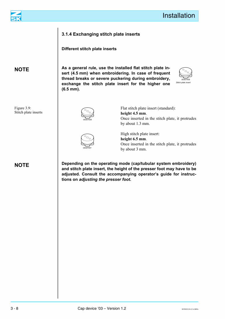
3.1.4 Exchanging stitch plate inserts
Different stitch plate inserts
NOTE As a general rule, use the installed flat stitch plate in-sert (4.5 mm) when embroidering. In case of frequentthread breaks or severe puckering during embroidery,exchange the stitch plate insert for the higher one(6.5 mm).
Stitch plate insert00307439
Figure 3.9: Stitch plate inserts
Flat stitch plate insert (standard):height 4.5 mm.Once inserted in the stitch plate, it protrudesby about 1.3 mm.
High stitch plate insert: height 6.5 mm.Once inserted in the stitch plate, it protrudesby about 3 mm.
NOTE Depending on the operating mode (cap/tubular system embroidery)and stitch plate insert, the height of the presser foot may have to beadjusted. Consult the accompanying operator’s guide for instruc-tions on adjusting the presser foot.
00307439
00307441
3 - 8 Cap device ’03 – Version 1.2 00783312.fm 21.4.08/Kx
Installation
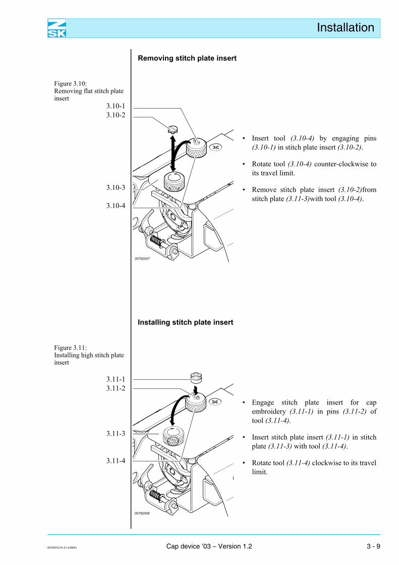
Removing stitch plate insert
Figure 3.10: Removing flat stitch plate insert
3.10-13.10-2
3.10-3
3.10-4
• Insert tool (3.10-4) by engaging pins(3.10-1) in stitch plate insert (3.10-2).
• Rotate tool (3.10-4) counter-clockwise toits travel limit.
• Remove stitch plate insert (3.10-2)fromstitch plate (3.11-3)with tool (3.10-4).
Installing stitch plate insert
Figure 3.11: Installing high stitch plate insert
3.11-13.11-2
3.11-3
3.11-4
• Engage stitch plate insert for capembroidery (3.11-1) in pins (3.11-2) oftool (3.11-4).
• Insert stitch plate insert (3.11-1) in stitchplate (3.11-3) with tool (3.11-4).
• Rotate tool (3.11-4) clockwise to its travellimit.
00782007
00782008
00783312.fm 21.4.08/Kx Cap device ’03 – Version 1.2 3 - 9
Installation
3 - 10 Cap device ’03 – Version 1.2 00783312.fm 21.4.08/Kx
Clamping the cap
4. Clamping the cap
4.1 Choice of caps for135/360 mm cap frame
The clamping technique is described below for:
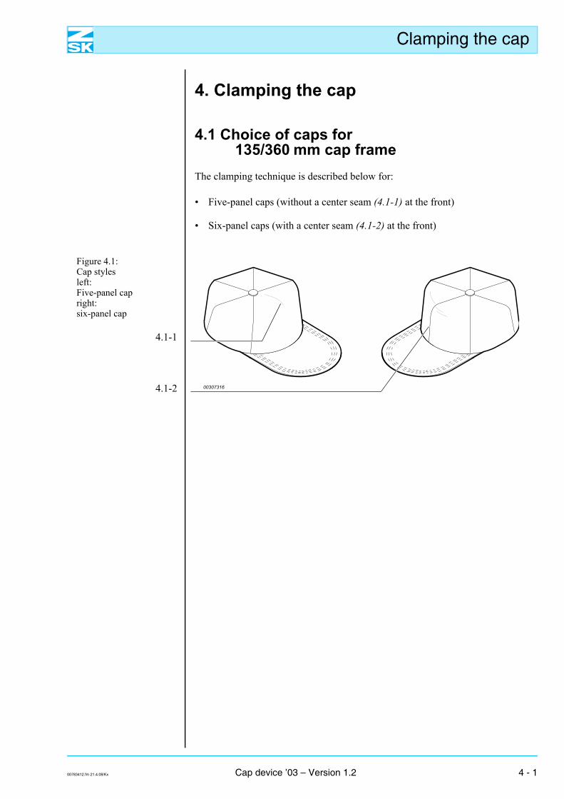
• Five-panel caps (without a center seam (4.1-1) at the front)
• Six-panel caps (with a center seam (4.1-2) at the front)
Figure 4.1: Cap stylesleft:Five-panel capright:six-panel cap
4.1-1
4.1-2 00307316
00783412.fm 21.4.08/Kx Cap device ’03 – Version 1.2 4 - 1
Clamping the cap
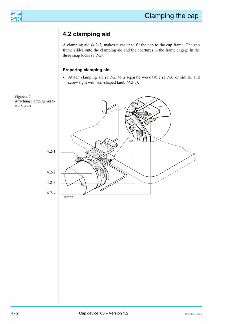
4.2 clamping aidA clamping aid (4.2-2) makes it easier to fit the cap to the cap frame. The capframe slides onto the clamping aid and the apertures in the frame engage in thethree snap locks (4.2-2).
Preparing clamping aid• Attach clamping aid (4.2-2) to a separate work table (4.2-3) or similar and
screw tight with star-shaped knob (4.2-4).
Figure 4.2: Attaching clamping aid to work table
4.2-1
4.2-2
4.2-3
4.2-400307412
00307413
4 - 2 Cap device ’03 – Version 1.2 00783412.fm 21.4.08/Kx
Clamping the cap
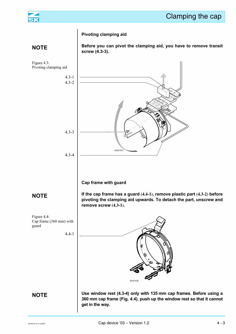
Pivoting clamping aid
NOTE Before you can pivot the clamping aid, you have to remove transitscrew (4.3-3).
Figure 4.3: Pivoting clamping aid
4.3-14.3-2
4.3-3
4.3-4
Cap frame with guard
NOTE If the cap frame has a guard (4.4-1), remove plastic part (4.3-2) beforepivoting the clamping aid upwards. To detach the part, unscrew andremove screw (4.3-1).
Figure 4.4: Cap frame (360 mm) with guard
4.4-1
NOTE Use window rest (4.3-4) only with 135 mm cap frames. Before using a360 mm cap frame (Fig. 4.4), push up the window rest so that it cannotget in the way.
00307410
00307436
00783412.fm 21.4.08/Kx Cap device ’03 – Version 1.2 4 - 3
Clamping the cap
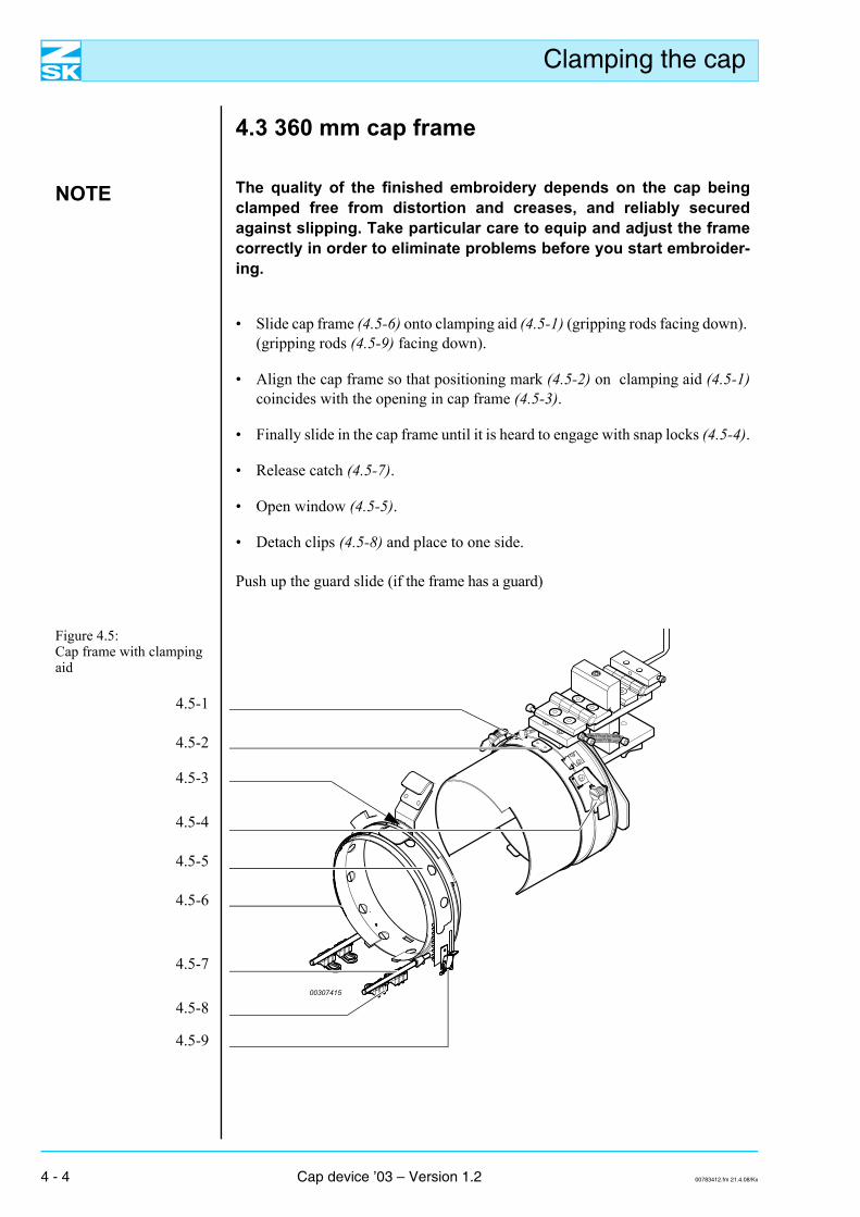
4.3 360 mm cap frame
NOTE The quality of the finished embroidery depends on the cap beingclamped free from distortion and creases, and reliably securedagainst slipping. Take particular care to equip and adjust the framecorrectly in order to eliminate problems before you start embroider-ing.
• Slide cap frame (4.5-6) onto clamping aid (4.5-1) (gripping rods facing down). (gripping rods (4.5-9) facing down).
• Align the cap frame so that positioning mark (4.5-2) on clamping aid (4.5-1)coincides with the opening in cap frame (4.5-3).
• Finally slide in the cap frame until it is heard to engage with snap locks (4.5-4).
• Release catch (4.5-7).
• Open window (4.5-5).
• Detach clips (4.5-8) and place to one side.
Push up the guard slide (if the frame has a guard)
Figure 4.5: Cap frame with clamping aid
4.5-1
4.5-2
4.5-3
4.5-4
4.5-5
4.5-6
4.5-7
4.5-8
4.5-9
00307415
4 - 4 Cap device ’03 – Version 1.2 00783412.fm 21.4.08/Kx
Clamping the cap
Clamping the cap
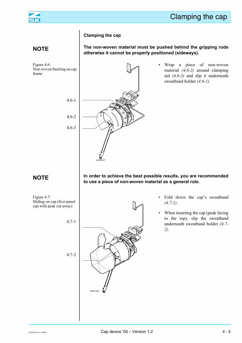
NOTE The non-woven material must be pushed behind the gripping rodsotherwise it cannot be properly positioned (sideways).
Figure 4.6: Non-woven backing on cap frame
4.6-1
4.6-2
4.6-3
• Wrap a piece of non-wovenmaterial (4.6-2) around clampingaid (4.6-3) and slip it underneathsweatband holder (4.6-1).
NOTE In order to achieve the best possible results, you are recommendedto use a piece of non-woven material as a general rule.
Figure 4.7: Sliding on cap (five-panel cap with peak cut away)
4.7-1
4.7-2
• Fold down the cap’s sweatband(4.7-1).
• When inserting the cap (peak facingto the top), slip the sweatbandunderneath sweatband holder (4.7-2).
00307417
00307420
00783412.fm 21.4.08/Kx Cap device ’03 – Version 1.2 4 - 5
Clamping the cap
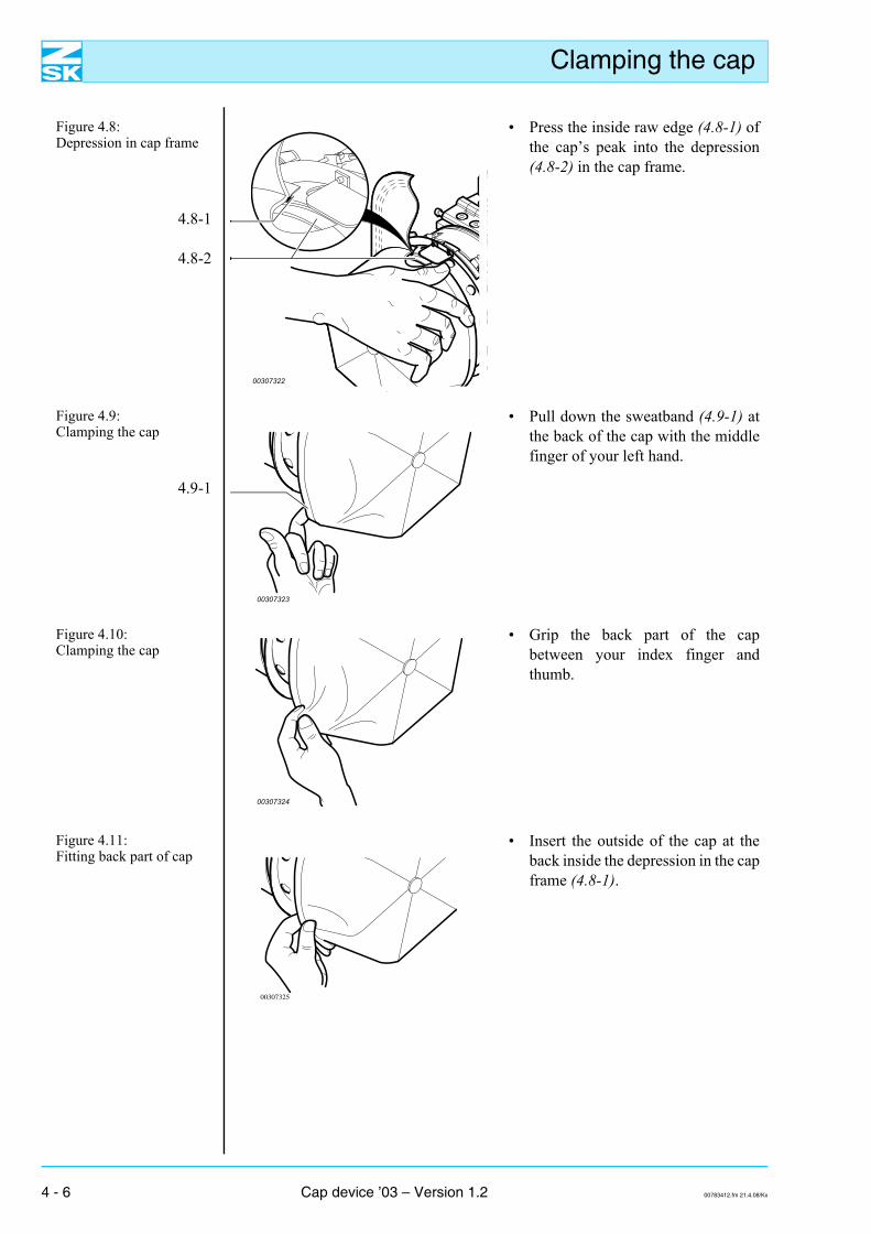
Figure 4.8: Depression in cap frame
4.8-1
4.8-2
• Press the inside raw edge (4.8-1) ofthe cap’s peak into the depression(4.8-2) in the cap frame.
Figure 4.9: Clamping the cap
4.9-1
• Pull down the sweatband (4.9-1) atthe back of the cap with the middlefinger of your left hand.
Figure 4.10: Clamping the cap
• Grip the back part of the capbetween your index finger andthumb.
Figure 4.11: Fitting back part of cap
• Insert the outside of the cap at theback inside the depression in the capframe (4.8-1).
00307322
00307323
00307324
00307325
4 - 6 Cap device ’03 – Version 1.2 00783412.fm 21.4.08/Kx
Clamping the cap
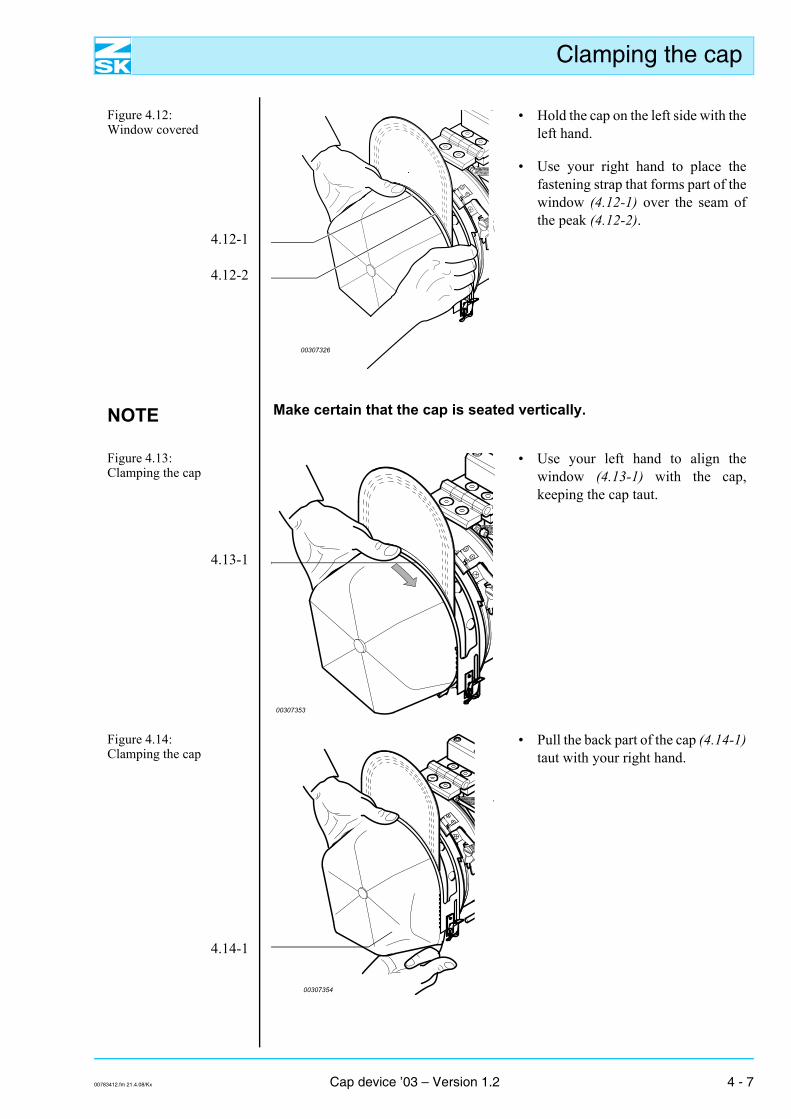
Figure 4.12: Window covered
4.12-1
4.12-2
• Hold the cap on the left side with theleft hand.
• Use your right hand to place thefastening strap that forms part of thewindow (4.12-1) over the seam ofthe peak (4.12-2).
NOTE Make certain that the cap is seated vertically.
Figure 4.13: Clamping the cap
4.13-1
• Use your left hand to align thewindow (4.13-1) with the cap,keeping the cap taut.
Figure 4.14: Clamping the cap
4.14-1
• Pull the back part of the cap (4.14-1)taut with your right hand.
00307326
00307353
00307354
00783412.fm 21.4.08/Kx Cap device ’03 – Version 1.2 4 - 7
Clamping the cap
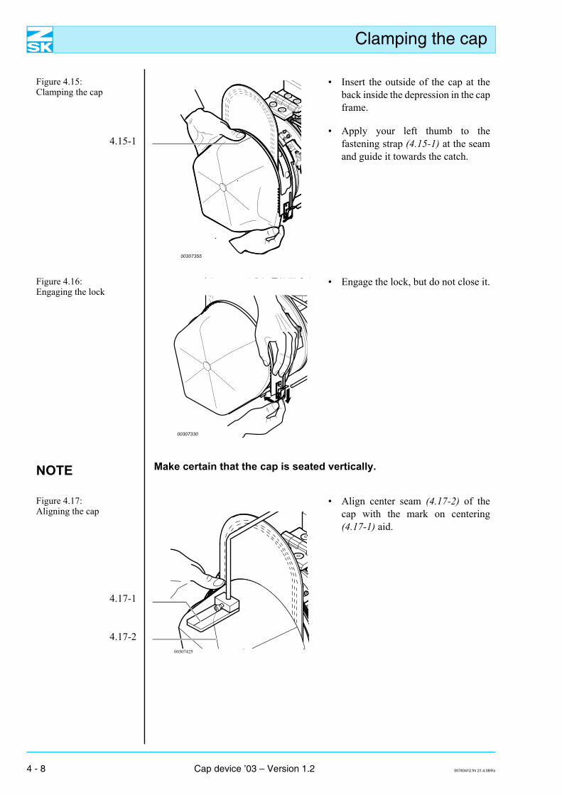
Figure 4.15: Clamping the cap
4.15-1
• Insert the outside of the cap at theback inside the depression in the capframe.
• Apply your left thumb to thefastening strap (4.15-1) at the seamand guide it towards the catch.
Figure 4.16: Engaging the lock
• Engage the lock, but do not close it.
NOTE Make certain that the cap is seated vertically.
Figure 4.17: Aligning the cap
4.17-1
4.17-2
• Align center seam (4.17-2) of thecap with the mark on centering(4.17-1) aid.
00307355
00307330
00307425
4 - 8 Cap device ’03 – Version 1.2 00783412.fm 21.4.08/Kx
Clamping the cap
Figure 4.18: Closing window catch
4.18-1
• Closing the catch (4.18-1)
Fastening clips
NOTE To make it easier to fasten the clips, you are recommended to swingthe clamping aid upwards on the hinge.
The gripping rods must extend into the cap.
Figure 4.19: Fastening clips
4.19-1
4.19-2
4.19-3
• Secure cap at both sides byfastening clips (4.19-1), with rings(4.19-2) facing inwards, to grippingrods (4.19-3).
• Swing the clamping aid back down.
00307356
00307434
00307435
00783412.fm 21.4.08/Kx Cap device ’03 – Version 1.2 4 - 9
Clamping the cap
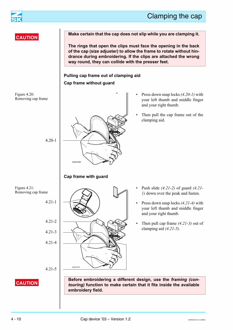
Make certain that the cap does not slip while you are clamping it.
The rings that open the clips must face the opening in the backof the cap (size adjuster) to allow the frame to rotate without hin-drance during embroidering. If the clips are attached the wrongway round, they can collide with the presser feet.
Pulling cap frame out of clamping aidCap frame without guard
Figure 4.20: Removing cap frame
4.20-1
• Press down snap locks (4.20-1) withyour left thumb and middle fingerand your right thumb.
• Then pull the cap frame out of theclamping aid.
Cap frame with guard
Figure 4.21: Removing cap frame
4.21-1
4.21-2
4.21-3
4.21-4
4.21-5
• Push slide (4.21-2) of guard (4.21-1) down over the peak and fasten.
• Press down snap locks (4.21-4) withyour left thumb and middle fingerand your right thumb.
• Then pull cap frame (4.21-3) out ofclamping aid (4.21-5).
00307426
00307427
00307401
Before embroidering a different design, use the framing (con-touring) function to make certain that it fits inside the availableembroidery field.
4 - 10 Cap device ’03 – Version 1.2 00783412.fm 21.4.08/Kx
Clamping the cap
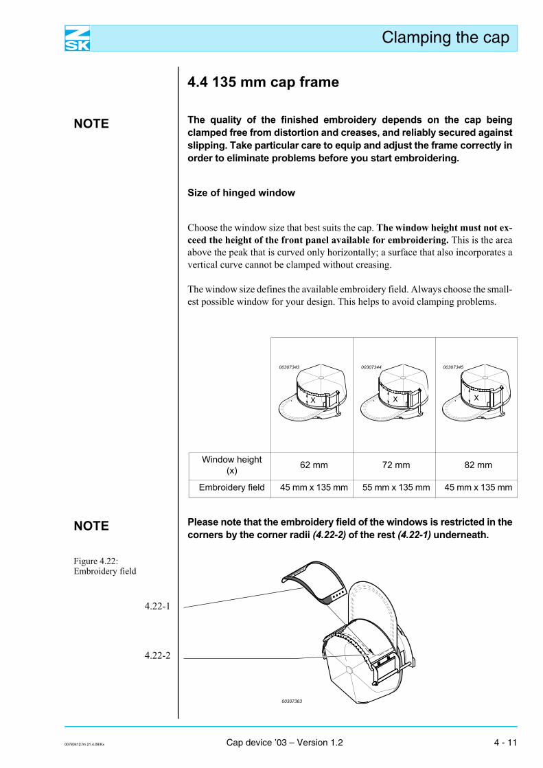
4.4 135 mm cap frame
NOTE The quality of the finished embroidery depends on the cap beingclamped free from distortion and creases, and reliably secured againstslipping. Take particular care to equip and adjust the frame correctly inorder to eliminate problems before you start embroidering.
Size of hinged window
Choose the window size that best suits the cap. The window height must not ex-ceed the height of the front panel available for embroidering. This is the areaabove the peak that is curved only horizontally; a surface that also incorporates avertical curve cannot be clamped without creasing.
The window size defines the available embroidery field. Always choose the small-est possible window for your design. This helps to avoid clamping problems.
Window height (x) 62 mm 72 mm 82 mm
Embroidery field 45 mm x 135 mm 55 mm x 135 mm 45 mm x 135 mm
X
00307343
X
00307344
X
00307345
NOTE Please note that the embroidery field of the windows is restricted in thecorners by the corner radii (4.22-2) of the rest (4.22-1) underneath.
Figure 4.22: Embroidery field
4.22-1
4.22-2
00307363
00783412.fm 21.4.08/Kx Cap device ’03 – Version 1.2 4 - 11
Clamping the cap
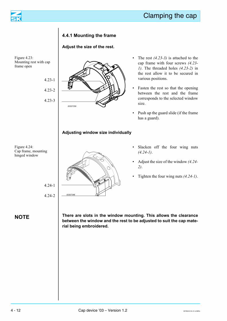
4.4.1 Mounting the frame
Adjust the size of the rest.
Figure 4.23: Mounting rest with cap frame open
4.23-1
4.23-2
4.23-3
• The rest (4.23-3) is attached to thecap frame with four screws (4.23-1). The threaded holes (4.23-2) inthe rest allow it to be secured invarious positions.
• Fasten the rest so that the openingbetween the rest and the framecorresponds to the selected windowsize.
• Push up the guard slide (if the framehas a guard).
Adjusting window size individually
Figure 4.24: Cap frame, mounting hinged window
4.24-1
4.24-2
• Slacken off the four wing nuts(4.24-1).
• Adjust the size of the window (4.24-2).
• Tighten the four wing nuts (4.24-1).
NOTE There are slots in the window mounting. This allows the clearancebetween the window and the rest to be adjusted to suit the cap mate-rial being embroidered.
00307359
00307348
4 - 12 Cap device ’03 – Version 1.2 00783412.fm 21.4.08/Kx
Clamping the cap
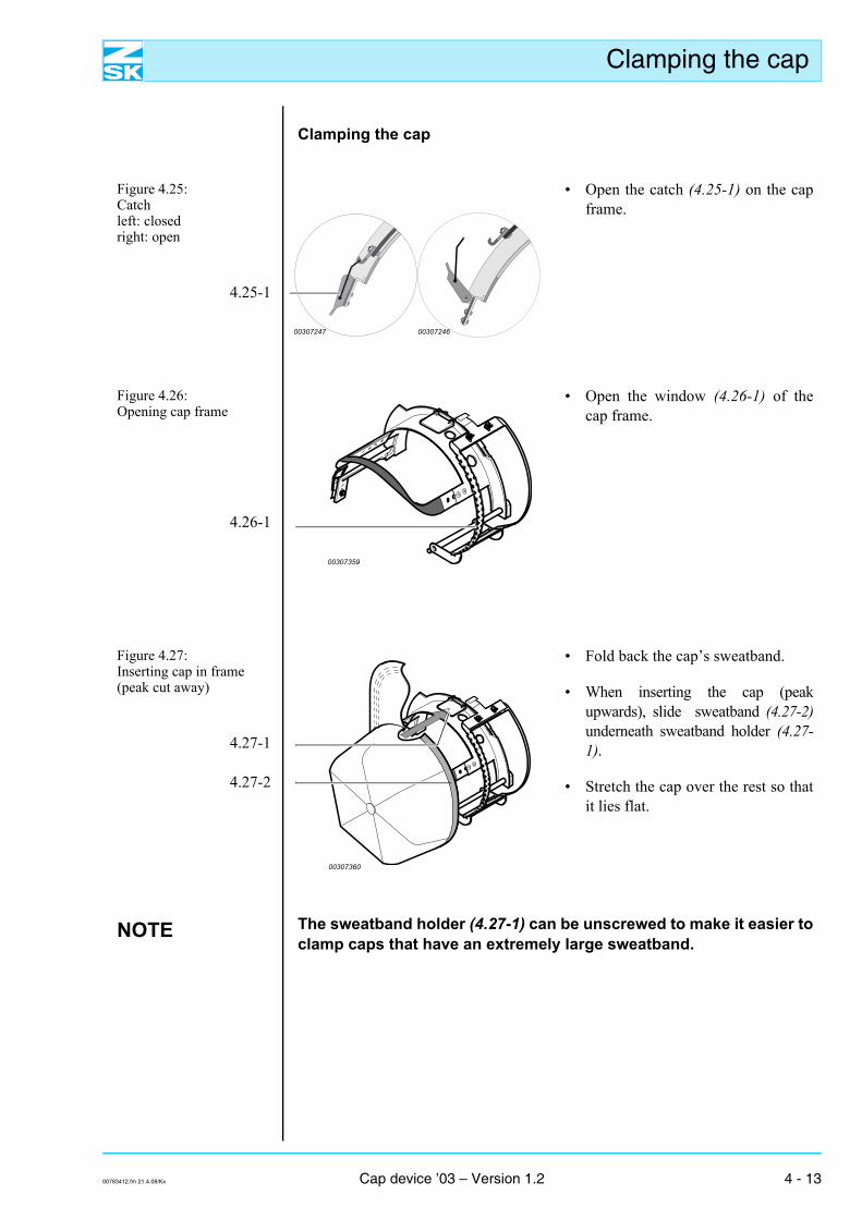
Clamping the cap
Figure 4.25: Catchleft: closedright: open
4.25-1
• Open the catch (4.25-1) on the capframe.
Figure 4.26: Opening cap frame
4.26-1
• Open the window (4.26-1) of thecap frame.
Figure 4.27: Inserting cap in frame (peak cut away)
4.27-1
4.27-2
• Fold back the cap’s sweatband.
• When inserting the cap (peakupwards), slide sweatband (4.27-2)underneath sweatband holder (4.27-1).
• Stretch the cap over the rest so thatit lies flat.
NOTE The sweatband holder (4.27-1) can be unscrewed to make it easier toclamp caps that have an extremely large sweatband.
00307247 00307246
00307359
00307360
00783412.fm 21.4.08/Kx Cap device ’03 – Version 1.2 4 - 13
Clamping the cap
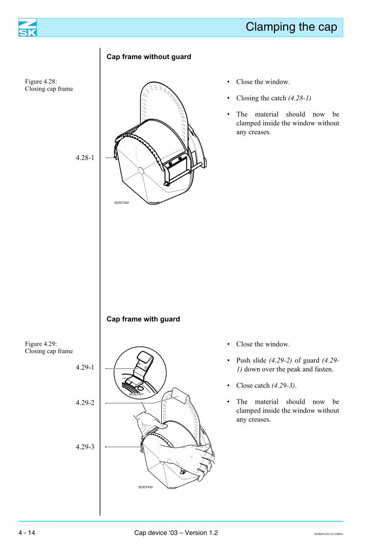
Cap frame without guard
Figure 4.28: Closing cap frame
4.28-1
• Close the window.
• Closing the catch (4.28-1)
• The material should now beclamped inside the window withoutany creases.
Cap frame with guard
Figure 4.29: Closing cap frame
4.29-1
4.29-2
4.29-3
• Close the window.
• Push slide (4.29-2) of guard (4.29-1) down over the peak and fasten.
• Close catch (4.29-3).
• The material should now beclamped inside the window withoutany creases.
00307342
00307430
00307401
4 - 14 Cap device ’03 – Version 1.2 00783412.fm 21.4.08/Kx
Clamping the cap
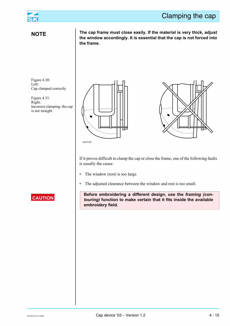
NOTE The cap frame must close easily. If the material is very thick, adjustthe window accordingly. It is essential that the cap is not forced intothe frame.
Figure 4.30: Left:Cap clamped correctly
Figure 4.31: Right:Incorrect clamping: the cap is not straight
If it proves difficult to clamp the cap or close the frame, one of the following faultsis usually the cause:
• The window (rest) is too large.
• The adjusted clearance between the window and rest is too small.
00307338
Before embroidering a different design, use the framing (con-touring) function to make certain that it fits inside the availableembroidery field.
00783412.fm 21.4.08/Kx Cap device ’03 – Version 1.2 4 - 15
Clamping the cap
4 - 16 Cap device ’03 – Version 1.2 00783412.fm 21.4.08/Kx
Inserting cap frame
5. Inserting cap frame
NOTE The method described here for inserting the cap frame is a commonprocedure that applies to both sizes, 135 mm and 360 mm.
Figure 5.1: Placing cap frame on cap drive.
5.1-1
5.1-2
5.1-3
5.1-4
5.1-5
5.1-6
5.1-7
• Before placing the cap frame on the drive, rotate it so that the peak (5.1-4) ishorizontal (5.1-7) and facing to the right.
• Place cap frame (5.1-6) on cap drive (5.1-1).
• Rotate the cap frame counter-clockwise through 90°.
• Align locating recess (5.1-3) on the cap frame with mating piece (5.1-2) on thecap drive.
• Slide in cap frame (5.1-6) until it engages in fasteners (5.1-5).
00782009
00400413
00400412
Check that the cap frame has properly engaged in all three snaplocks.
00783512.fm 21.4.08/Kx Cap device ’03 – Version 1.2 5 - 1
Inserting cap frame
5.1 Preparing for embroidering
5.1.1 Selecting the needle
NOTE The stiffer the material at the area being embroidered, the strongerthe needle that you require. In particular, stronger needles are re-quired for caps that have a center seam.
As a general rule, do not embroider caps with needles smaller thansize 80.
Consult the accompanying Operator's Guide for further informationon the choice of needle.
5.1.2 Loading a design - JAF/JAFA series
Before selecting the design, check that the cap drive is locatedin the center position.
Each time you convert the machine for a different mode, changethe pantograph configuration to suit the application (e.g. ZSKcap attachment ’99) by way of the control unit.
Checking center position of cap drive
Figure 5.2: JAF/JAFA series, checking center position of cap drive
• Transverse (side to side) alignment(Y axis): Pointer set to position 0 on the scale.
• Longitudinal (front to back): alignment(X axis):Adjust the pantograph drive to the frontby way of the control unit so that thepointer is set to position 0 on the scale.
00307335
5 - 2 Cap device ’03 – Version 1.2 00783512.fm 21.4.08/Kx
Inserting cap frame
NOTE With a head spacing of 495 mm (example: JAF 0411-495), the side-to-side alignment (Y axis) is marked by asymbol indicating the center position of the cap drive
Symbol,alignment with 495 mm
head spacing
000307362
The procedures for Load design, Framing (contouring) and Embroider designare described in detail in the manual accompanying the relevant control unit.
5.1.3 Loading design - SPRINT 2/SPRINT 4
Before selecting the design, check that the cap drive is locatedin the center position.
Each time you convert the machine for a different mode, changethe pantograph configuration to suit the application (e.g. ZSKcap attachment ’99) by way of the control unit.
Checking center position of cap drive
Figure 5.3: Checking center position of cap drive
• Longitudinal (front to back) alignment(X axis):Move the pantograph drive to the center ofthe scale with the control unit.
The procedures forLoad design, Framing (contouring) and Embroider designare described in detail in the manual accompanying the relevant control unit.
05 10 15 20 25 30 35 40 45 50 55 60 65 70
00307437
00783512.fm 21.4.08/Kx Cap device ’03 – Version 1.2 5 - 3
Inserting cap frame
5 - 4 Cap device ’03 – Version 1.2 00783512.fm 21.4.08/Kx
Notes on punching
6. Notes on punching
As a general rule, cap embroidery is made difficult by the curvature of the cap,which prevents the area being embroidered from being placed flat on the stitchplate. An additional problem is caused by the center seam of six-panel caps, whichinfringes the embroidery area.
To counteract these problems, observe the basic rules described here when punch-ing cap designs. Edit existing designs intended for “conventional” embroideringbefore using them on caps. The use of suitable designs not only enhances the qual-ity of the embroidery, but also helps to avoid malfunctions, such as thread breaks,so that machine productivity is improved.
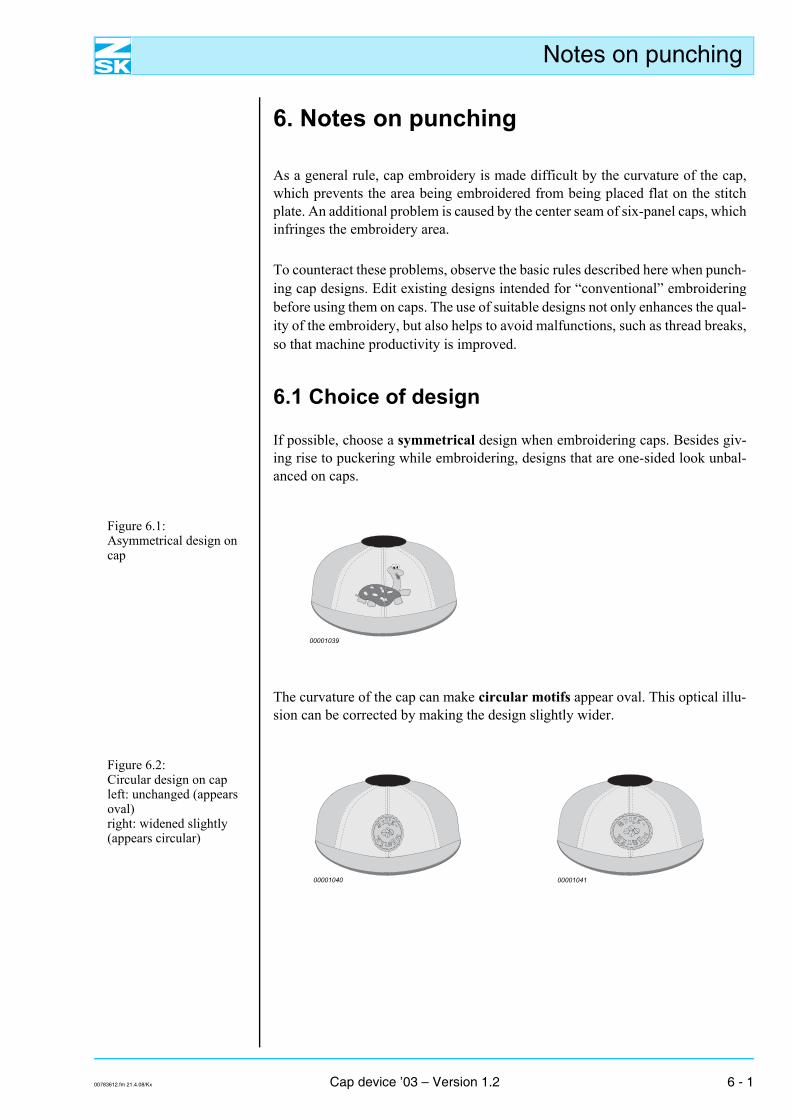
6.1 Choice of design
If possible, choose a symmetrical design when embroidering caps. Besides giv-ing rise to puckering while embroidering, designs that are one-sided look unbal-anced on caps.
Figure 6.1: Asymmetrical design on cap
The curvature of the cap can make circular motifs appear oval. This optical illu-sion can be corrected by making the design slightly wider.
Figure 6.2: Circular design on capleft: unchanged (appears oval)right: widened slightly (appears circular)
00001039
00001040 00001041
00783612.fm 21.4.08/Kx Cap device ’03 – Version 1.2 6 - 1
Notes on punching
6.2 Cap designs in general
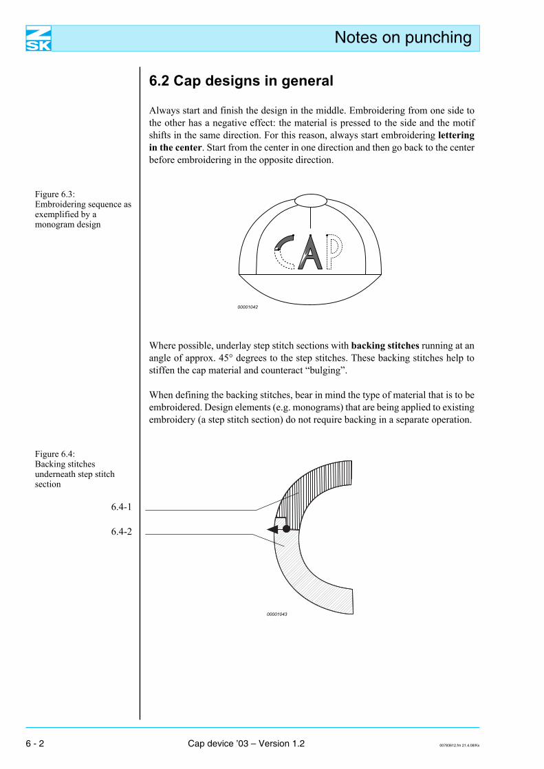
Always start and finish the design in the middle. Embroidering from one side tothe other has a negative effect: the material is pressed to the side and the motifshifts in the same direction. For this reason, always start embroidering letteringin the center. Start from the center in one direction and then go back to the centerbefore embroidering in the opposite direction.
Figure 6.3: Embroidering sequence as exemplified by a monogram design
Where possible, underlay step stitch sections with backing stitches running at anangle of approx. 45° degrees to the step stitches. These backing stitches help tostiffen the cap material and counteract “bulging”.
When defining the backing stitches, bear in mind the type of material that is to beembroidered. Design elements (e.g. monograms) that are being applied to existingembroidery (a step stitch section) do not require backing in a separate operation.
Figure 6.4: Backing stitches underneath step stitch section
6.4-1
6.4-2
00001042
00001043
6 - 2 Cap device ’03 – Version 1.2 00783612.fm 21.4.08/Kx
Notes on punching
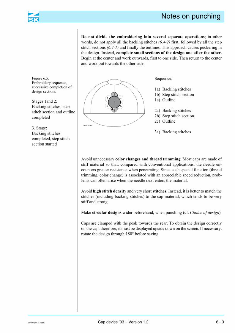
Do not divide the embroidering into several separate operations; in otherwords, do not apply all the backing stitches (6.4-2) first, followed by all the stepstitch sections (6.4-1) and finally the outlines. This approach causes puckering inthe design. Instead, complete small sections of the design one after the other.Begin at the center and work outwards, first to one side. Then return to the centerand work out towards the other side.
Figure 6.5: Embroidery sequence, successive completion of design sections
Stages 1and 2:Backing stitches, step stitch section and outline completed
3. Stage:Backing stitches completed, step stitch section started
Sequence:
1a) Backing stitches1b) Step stitch section1c) Outline
2a) Backing stitches2b) Step stitch section2c) Outline
3a) Backing stitches
Avoid unnecessary color changes and thread trimming. Most caps are made ofstiff material so that, compared with conventional applications, the needle en-counters greater resistance when penetrating. Since each special function (threadtrimming, color change) is associated with an appreciable speed reduction, prob-lems can often arise when the needle next enters the material.
Avoid high stitch density and very short stitches. Instead, it is better to match thestitches (including backing stitches) to the cap material, which tends to be verystiff and strong.
Make circular designs wider beforehand, when punching (cf. Choice of design).
Caps are clamped with the peak towards the rear. To obtain the design correctlyon the cap, therefore, it must be displayed upside down on the screen. If necessary,rotate the design through 180° before saving.
3
6
42
5
71
00001044
00783612.fm 21.4.08/Kx Cap device ’03 – Version 1.2 6 - 3
Notes on punching
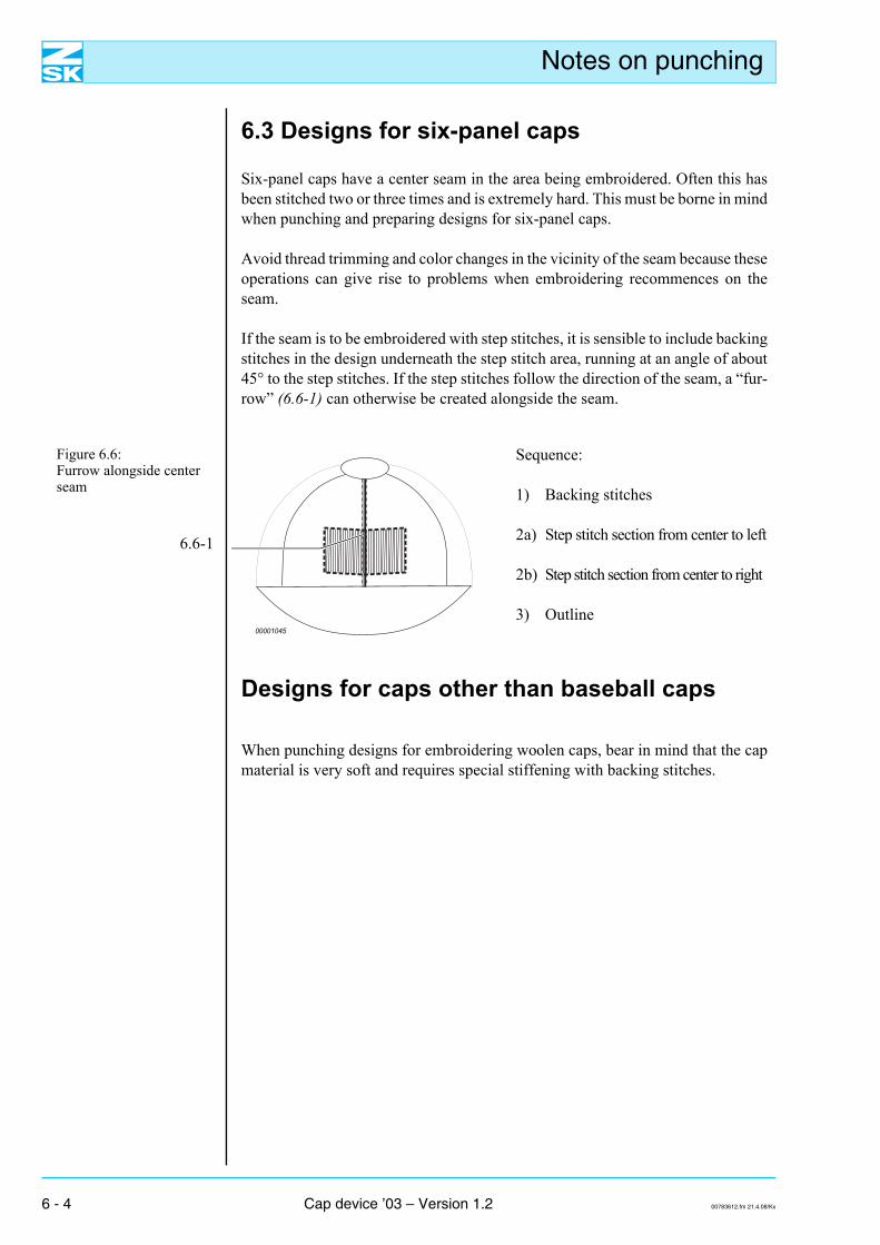
6.3 Designs for six-panel caps
Six-panel caps have a center seam in the area being embroidered. Often this hasbeen stitched two or three times and is extremely hard. This must be borne in mindwhen punching and preparing designs for six-panel caps.
Avoid thread trimming and color changes in the vicinity of the seam because theseoperations can give rise to problems when embroidering recommences on theseam.
If the seam is to be embroidered with step stitches, it is sensible to include backingstitches in the design underneath the step stitch area, running at an angle of about45° to the step stitches. If the step stitches follow the direction of the seam, a “fur-row” (6.6-1) can otherwise be created alongside the seam.
Figure 6.6: Furrow alongside center seam
6.6-1
Sequence:
1) Backing stitches
2a) Step stitch section from center to left
2b) Step stitch section from center to right
3) Outline
Designs for caps other than baseball caps
When punching designs for embroidering woolen caps, bear in mind that the capmaterial is very soft and requires special stiffening with backing stitches.
00001045
6 - 4 Cap device ’03 – Version 1.2 00783612.fm 21.4.08/Kx
Troubleshooting
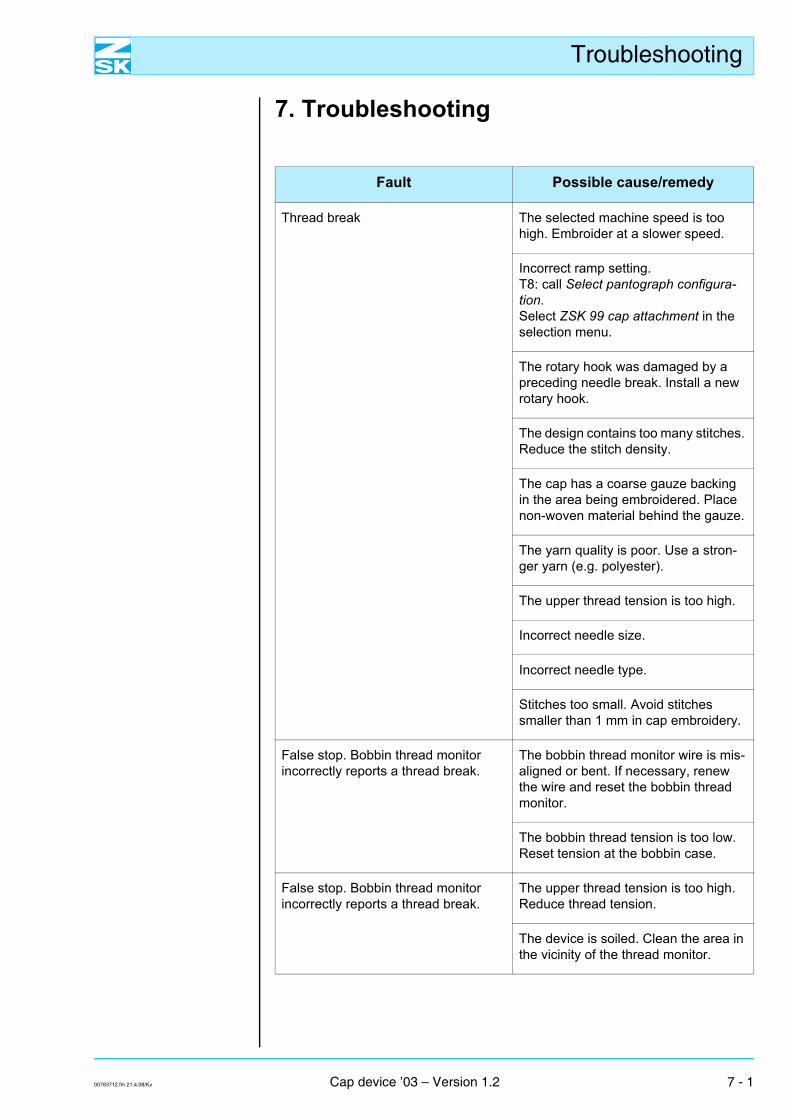
7. Troubleshooting
Fault Possible cause/remedy
Thread break The selected machine speed is too high. Embroider at a slower speed.
Incorrect ramp setting. T8: call Select pantograph configura-tion. Select ZSK 99 cap attachment in the selection menu.
The rotary hook was damaged by a preceding needle break. Install a new rotary hook.
The design contains too many stitches. Reduce the stitch density.
The cap has a coarse gauze backing in the area being embroidered. Place non-woven material behind the gauze.
The yarn quality is poor. Use a stron-ger yarn (e.g. polyester).
The upper thread tension is too high.
Incorrect needle size.
Incorrect needle type.
Stitches too small. Avoid stitches smaller than 1 mm in cap embroidery.
False stop. Bobbin thread monitor incorrectly reports a thread break.
The bobbin thread monitor wire is mis-aligned or bent. If necessary, renew the wire and reset the bobbin thread monitor.
The bobbin thread tension is too low. Reset tension at the bobbin case.
False stop. Bobbin thread monitor incorrectly reports a thread break.
The upper thread tension is too high. Reduce thread tension.
The device is soiled. Clean the area in the vicinity of the thread monitor.
00783712.fm 21.4.08/Kx Cap device ’03 – Version 1.2 7 - 1
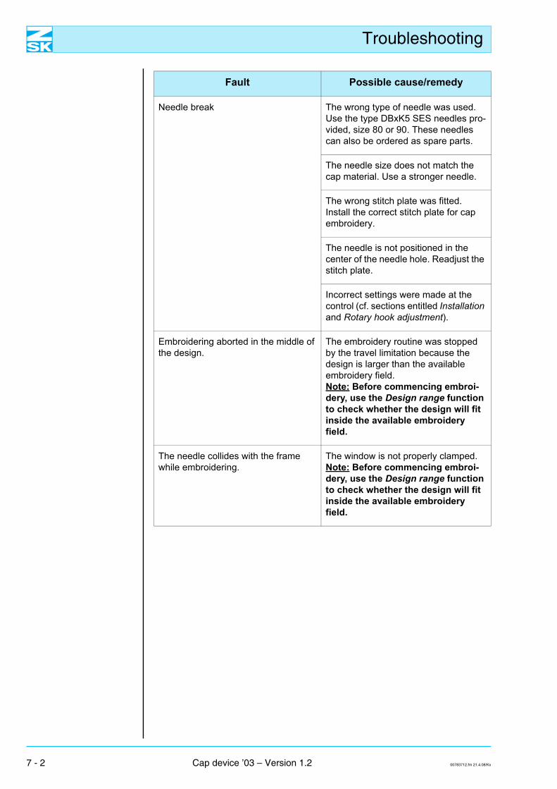
Troubleshooting
Needle break The wrong type of needle was used. Use the type DBxK5 SES needles pro-vided, size 80 or 90. These needles can also be ordered as spare parts.
The needle size does not match the cap material. Use a stronger needle.
The wrong stitch plate was fitted. Install the correct stitch plate for cap embroidery.
The needle is not positioned in the center of the needle hole. Readjust the stitch plate.
Incorrect settings were made at the control (cf. sections entitled Installation and Rotary hook adjustment).
Embroidering aborted in the middle of the design.
The embroidery routine was stopped by the travel limitation because the design is larger than the available embroidery field.Note: Before commencing embroi-dery, use the Design range function to check whether the design will fit inside the available embroidery field.
The needle collides with the frame while embroidering.
The window is not properly clamped.Note: Before commencing embroi-dery, use the Design range function to check whether the design will fit inside the available embroidery field.
Fault Possible cause/remedy
7 - 2 Cap device ’03 – Version 1.2 00783712.fm 21.4.08/Kx
Troubleshooting
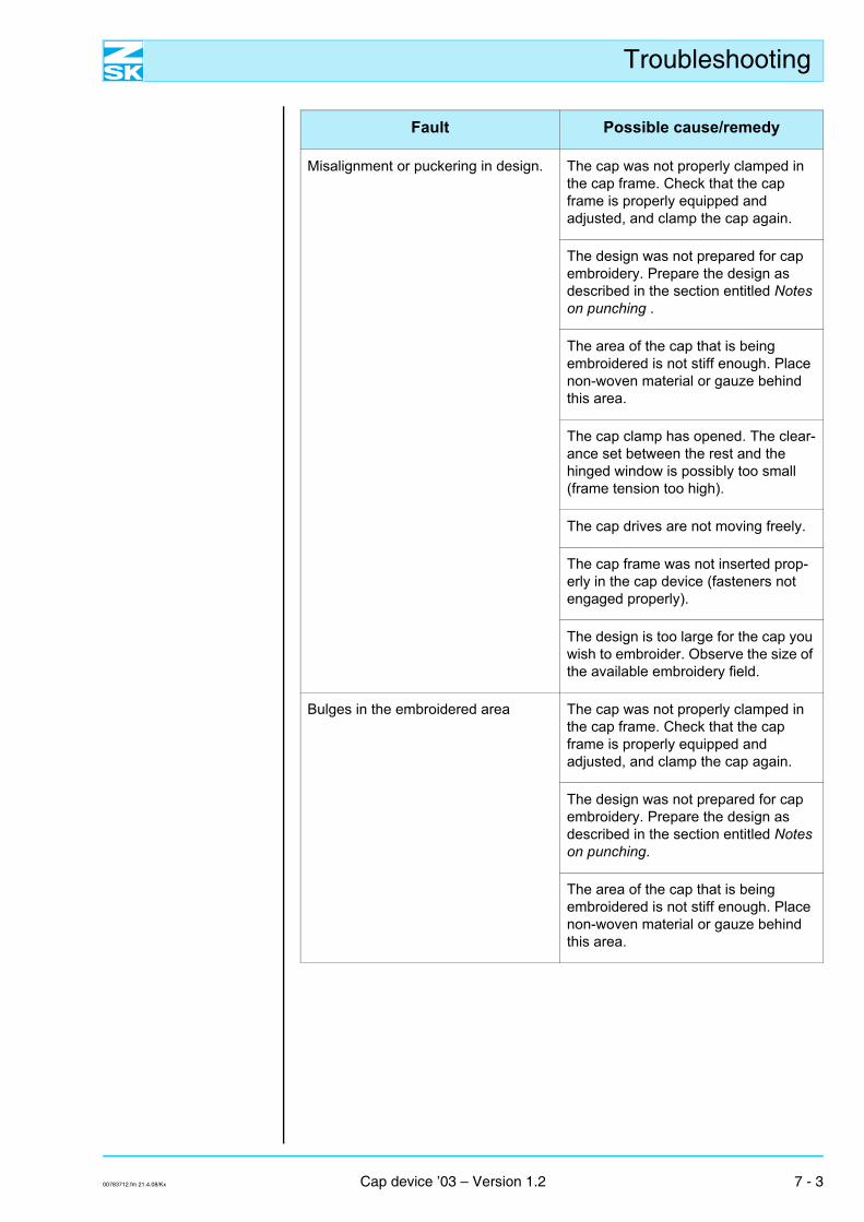
Misalignment or puckering in design. The cap was not properly clamped in the cap frame. Check that the cap frame is properly equipped and adjusted, and clamp the cap again.
The design was not prepared for cap embroidery. Prepare the design as described in the section entitled Notes on punching .
The area of the cap that is being embroidered is not stiff enough. Place non-woven material or gauze behind this area.
The cap clamp has opened. The clear-ance set between the rest and the hinged window is possibly too small (frame tension too high).
The cap drives are not moving freely.
The cap frame was not inserted prop-erly in the cap device (fasteners not engaged properly).
The design is too large for the cap you wish to embroider. Observe the size of the available embroidery field.
Bulges in the embroidered area The cap was not properly clamped in the cap frame. Check that the cap frame is properly equipped and adjusted, and clamp the cap again.
The design was not prepared for cap embroidery. Prepare the design as described in the section entitled Notes on punching.
The area of the cap that is being embroidered is not stiff enough. Place non-woven material or gauze behind this area.
Fault Possible cause/remedy
00783712.fm 21.4.08/Kx Cap device ’03 – Version 1.2 7 - 3
Troubleshooting
Cap puckered, design off-center. The design was not prepared for cap embroidery. Prepare the design as described in the section entitled Notes on punching.
The cap was not properly clamped in the cap frame. Check that the cap frame is properly equipped and adjusted, and clamp the cap again.
“Furrows” in the design. The design did not contain any backing stitches in the vicinity of the cap seam. Prepare the design as described in the section entitled Notes on punching.
Cap device is noisy. Too much play in cap device drive.
The screws that secure the cap device were not properly tightened. Take up slack.
Fault Possible cause/remedy
7 - 4 Cap device ’03 – Version 1.2 00783712.fm 21.4.08/Kx
Index
Index
Numerics135 mm cap frame 2 - 1
4 - 11135 mm frame 2 - 1360 mm cap frame 2 - 1
4 - 4360 mm frame 2 - 1
4 - 4
AAborted embroidery routine 7 - 2Adapter plate 2 - 1Aligning cap 4 - 8Aligning the cap 4 - 8Attachments 3 - 1
BBack part of cap 4 - 7Backing stitches 6 - 2
6 - 36 - 4
Basic principles 1 - 1Basic rules for punching 6 - 1Basic rules of cap embroidery 1 - 1Bobbin thread monitor, thread break 7 - 1Bulges 7 - 3
CCap designs in general 6 - 2Cap device 1 - 1Cap device, noisy 7 - 4Cap drive 2 - 1
3 - 4Cap drive in center position 5 - 2
5 - 3Cap drive,
dismantling 3 - 7installing 3 - 4
Cap embroidery 6 - 1Cap frame 4 - 2
4 - 44 - 64 - 8
4 - 12Cap frame with guard 4 - 3
4 - 10Cap frame without guard 4 - 10Cap frame, pulling out of clamping aid 4 - 10Cap material 1 - 5
6 - 4Cap puckered 7 - 4
Caps 1 - 11 - 2
4 - 135 - 26 - 16 - 3
Caps with center seam 5 - 2Caps, choice of 4 - 1Catch 2 - 1Catch of 135 mm cap frame 4 - 13
4 - 14Catch of 360 mm cap frame 4 - 9Catch,
left 3 - 4right 3 - 4
Center position of cap drive, JAF/JAFA series 5 - 2SPRINT 2/SPRINT 4 series 5 - 3
Center position of scales (front to back) 3 - 3Center seam 1 - 4
6 - 4Center seam infringing embroidery area 6 - 1Centering aid 4 - 8Choice of design 6 - 1Circular designs 6 - 1
6 - 3Clamping 1 - 4Clamping aid 2 - 1
4 - 24 - 4
Clamping problems 4 - 11Clamping the cap 1 - 2
1 - 34 - 1
Clamping the cap, 135 mm frame 4 - 13360 mm frame 4 - 5
Clamping, 135 mm frame 4 - 13360 mm frame 4 - 5
Clip 2 - 1Clips 4 - 4
4 - 10Color change 6 - 3
6 - 4Converting machine for cap embroidery 3 - 1Cover plate 3 - 4
00783t12MIX.fm 21.4.08/Ch,Kx Cap device ’03 – Version 1.2 Index - 1
Index
DDesign 1 - 2
1 - 34 - 104 - 114 - 15
6 - 3Design sections 6 - 3Design, loading 5 - 2
5 - 3Designs for caps other than baseball caps 6 - 4Designs for six-panel caps 6 - 4Determining center position 3 - 2Determining center position (lateral alignment) 3 - 2Direction of seam 6 - 4
EEmbroidering 1 - 4Embroidering aborted 7 - 2Embroidering restarting 6 - 4Embroidery area 1 - 3
5 - 26 - 4
Embroidery field 1 - 14 - 104 - 114 - 15
Embroidery quality 1 - 36 - 1
Existing designs 1 - 2
FFalse stops 7 - 1Fastener 2 - 1
4 - 44 - 10
5 - 1Fastening clips 4 - 9Fastening strap of window 4 - 7
4 - 8Fitting cap to cap frame 4 - 2Five panel caps 1 - 3
1 - 4Five-panel caps 1 - 3
1 - 44 - 1
Fixing caps (not baseball caps) 1 - 6Frame with guard 4 - 3Frames, choice of 4 - 1Framing (contouring) 4 - 10
4 - 15Front position, determining 3 - 2“Furrows” in the design 7 - 4Furrow alongside seam 6 - 4
GGripping rods 2 - 1
4 - 9Guard 2 - 1
HHeight of cap front 1 - 1Height of front area 1 - 1Hinged window, size 4 - 11
IInserting cap frame 5 - 1Inside raw edge 4 - 6Installing cap device ’03 3 - 1
KKnurled screw 2 - 1
3 - 4
LLongitudinal (front-to-back) alignment
(JAF/JAFA) 3 - 2
MMark on centering aid 4 - 8Maximum size of design 1 - 1Monograms, starting in center 6 - 2Mounting 3 - 4
NNeedle 1 - 2
1 - 45 - 26 - 3
Needle bar 3 - 1Needle break 7 - 2Needle collision 7 - 2Needle entering material 6 - 3Needle selection 5 - 2Non-woven material 1 - 1
1 - 21 - 54 - 5
Non-woven stiffening 1 - 1
Ooffset 7 - 3Opening in back of cap (size adjuster) 4 - 10Other caps 1 - 1
1 - 5Outlines 6 - 3
PParked position 3 - 1Peak in horizontal position 5 - 1
Index - 2 Cap device ’03 – Version 1.2 00783t12MIX.fm 21.4.08/Ch,Kx
Index
Placing work flat 1 - 14 - 114 - 134 - 156 - 1
Polyester yarn 7 - 1Preparing for embroidering 5 - 2Presser foot 4 - 10Puckering 1 - 3
7 - 3Punching 1 - 4
6 - 16 - 3
Punching for woolen caps 6 - 4
RRaw edge 4 - 6
SScale position 5 - 2Seam 6 - 4Six-panel caps 1 - 4
4 - 16 - 16 - 4
Size of window 4 - 11Snap locks 4 - 10Speed 6 - 3Star-shaped knob 4 - 2Step stitch area 6 - 2
6 - 36 - 4
Step stitch direction 6 - 26 - 4
Step stitches, path traced by 6 - 4Stitch density 6 - 3Stitch length 6 - 3Stitch plate insert 3 - 9Stitch plate insert,
border frame or tabletop embroidery 3 - 8cap embroidery 3 - 2
3 - 8exchanging 3 - 8installing 3 - 9removing 3 - 9
Stitch plate inserts, different 3 - 8Stitches 6 - 3Stronger needle 5 - 2Suitable design 6 - 1Sweatband 1 - 3
4 - 54 - 13
Sweatband at back of cap 4 - 6Sweatband extremely long 4 - 13Sweatband holder 2 - 1
4 - 54 - 13
Symmetrical design 6 - 1
TThread break 7 - 1Thread breaks, avoiding 6 - 1Tool, stitch plate insert 3 - 9Transverse (side to side) alignment 3 - 2Travel limitation 7 - 2Trimming 6 - 3
6 - 4Troubleshooting 7 - 1
WWindow 4 - 4
4 - 114 - 124 - 134 - 15
Window fastening strap 4 - 7Window height 4 - 11Window size 4 - 11
4 - 12Wing nuts 4 - 12Wire 3 - 4
00783t12MIX.fm 21.4.08/Ch,Kx Cap device ’03 – Version 1.2 Index - 3

Index
Index - 4 Cap device ’03 – Version 1.2 00783t12MIX.fm 21.4.08/Ch,Kx


![OpenDNSSECチュートリアル2009/11/24 · [参考]DNSSEC Key Timing, John A Dickinson, Hohan Ihrenm, Stephen Morris@IETF76 Sign with new ZSK Remove old ZSK Add new ZSK,Sign with](https://img.pdfslide.net/doc/110x75/5f10b5b17e708231d44a70d4/opendnssecffffff-20091124-efdnssec-key-timing-john-a.jpg)