Embed Size (px)
Citation preview

ESD.33 -- Systems Engineering
Operating Windows forOperating Windows forRobust Concept Design
(and other advanced topics in Robust Design)Robust Design)
Dan Frey

•
Plan for the SessionPlan for the Session
From last time: a new research result• Operating window methodsOperating window methods • Concept design strategies
– Relax a constraint limit … – Use physics of incippient failure to avoid failure p y – Create two distinct operating modes … – Exploit interdependence Exploit interdependence …
• Adaptive OFAT for robust design • Noise strategy

More Observations of IndustryMore Observations of Industry
• Time for design (concept to market) is going down
• Fewer physical experiments are being conductedphysical experiments are being conductedFewer • Greater reliance on computation / CAE • Poor answers in computer modeling are commonPoor answers in computer modeling are common
– Right model → Inaccurate answer – Right model → No answer whatsoever Right model → No answer whatsoever – Not-so right model → Inaccurate answer
• Unmodeled effects • Bugs in coding the model

t t
Human Subjects ExperimentHuman Subjects Experiment
• HHypothhesiis: EEngiineers usiing a flfl awedd s iimullatiion are more likely to detect the flaw while usingOFAT than while using a more complex designOFAT than while using a more complex design.
• Method: Between-subjects experiment withh bj ( ) f ihuman subjectts (engiineers) performingparameter design with OFAT vs. designed experimentexperiment.
Savoie, Troy B., 2010, Human detection of computer simulation mistakes in engineering experiments,” PhD thesis, Massachusetts Institute of Technology.

Device Used as the Topic of Consideration in the Experiment
Courtesy of Troy B. Savoie. Used with permission.

Factors and their Experimentally Determined Effects
Courtesy of Troy B. Savoie. Used with permission.

Results of Human Subjects ExperimentResults of Human Subjects Experiment
• Pilot with N = 8 • Study with N = 55 (1 withdrawal) •• External validity high External validity high
– 50 full time engineers and 5 engineering students
– i d f 6 t 40+experience ranged from 6 mo. to 40+ yr. • Outcome measured by subject debriefing at end
MethodMethod DetectedDetected Not detected Not detected Detection Rate (95% CI) Detection Rate (95% CI) OFAT 14 13 (0.3195,0.7133) PBL8PBL8 11 2626 (0 0009 0 1897) (0.0009,0.1897)

Registering SurpriseRegistering Surprise
Courtesy of Troy B. Savoie. Used with permission.

•
Preliminary Conclusions from this Investigation
• Computer simulations are an increasingly critical part of Systems Engineeringcritical part of Systems Engineering
• As confident as you may be in your models they probably still have mistakes models, they probably still have mistakes in them
• Simplification of your search strategy willSimplification of your search strategy will make you more capable of perceivingerrors in computer simulationserrors in computer simulations

•
Plan for the SessionPlan for the Session
• From last time: a new research resultOperating window methodsOperating window methods
• Concept design strategies – Relax a constraint limit … – Use physics of incippient failure to avoid failure p y – Create two distinct operating modes … – Exploit interdependence Exploit interdependence …
• Adaptive OFAT for robust design • Noise strategy

Reliability and SystemsReliability and SystemsEngineeringEngineering
• Reliability is among the most importantReliability is among the most important topics in systems engineering
• Reliability is the proper functioning of the syystem under the full rangge of conditions experienced in the field
•• Reliability requires robustness Reliability requires robustness

Definitions of Reliability
• In its traditional formulation reliability isIn its traditional formulation reliability is stated as the probability of failure under specified operating conditionsspecified operating conditions
• Here, we expplore a concepption of reliabilityy as failure-mode avoidance

•
Advantages of this Conception
• Rooted in the physics of the failureRooted in the physics of the failure • More appropriate to early stages of SE • An enhancement to creativity • Requires less informationRequires less information

One-sided Failure Modes
• The failure occurs at only one end of a i f t ’noise factor’s range
Response ( ) UY <ZXLimiting value
Failure mode inequality
Response
X1
( ) 2112 , UY <ZX
Design Parameter orControl factor Failure mode boundary
Noise factor
Z1Clausing, D. and D. D. Frey, D. D., 2004, “Failures Modes and Two Types of Robustness,” 14th INCOSE Symposium,Tolouse, FR.

Operating Windows • Operating window = the range of noise
factors satisfying all failure mode criteriafactors satisfying all failure mode criteria
Y (X Z )> L Y (X Z )< U
X1
( ) 2112 , UY <ZX
( ) ( ){ }UYLY <′<′ ZXZXZ
( ) 1111 , LY >ZX
Broad operating window
( ) ( ){ Y<( }ULY <ZXZXZ
( ) ( ){ },,, 212111 UYLY << ZXZXZ
) ( ){ },,, 212111 UYLY << ZXZXZ Narrow operating window
Z1

′
Concept Design Z2 Z2
Y3(X′,Z)< U3Y (XZ)< U( ) 33 , UY <ZX
( ) ( ) 22 , UY <ZX
( ){ }31for, …∈∈ iWY ii ZXZ
( ) 11 , LY >ZX
( ) 33
( ){ }
( ) 22 , UY <′ ZX( ) LY >′ ZX
( ){ }31for, …∈∈′ iWY ii ZXZ
( )( ) 11 , LY >ZX
Z1 Z1
• A conceptual design change can create a larger operating windowcreate a larger operating window

A TheoremA Theorem
Operating Windows and Conceptual Design -- If the conceptual design of a system is
changed including a change in functional responses Yi to iY ′ and corresponding design
′parameter changes from X to X′ and the new operating window holds the old operating
window as a subset ( ){ }∈∈ allfor , iWY ii ZXZ ( ){ } allfor , iWY ii ∈′′ ZXZ , then reliability
has improved.
• Reliability improved regardless of probability distribution

Relax a Constraint Limit on anRelax a Constraint Limit on anUncouppled Control Factor
• When a system variable only affects one ofWhen a system variable only affects one of the …failure modes, take its value to its constraint limit seek new architectures or constraint limit… seek new architectures or technologies that relax the constraint.

Primary Example of the Strategy
Wrap angle
R t d R
Feed Belt
Papper Stack Retard Rollll
Wrap angle
It was known that increasing wrap angle tended to improve multifeed reliability and not particularly improve multifeed reliability and not particularly hamper misfeed reliability. Still, most copiers only had about 13 degrees of wrap angle.
Courtesy of Wiley Periodicals. Used with permission.

Primary Example of the Strategy
Architecture with nearly Architecture with loopinglinear paper path paper path
A newer architecture on the right has a looping paper path, which enabled a larger wrap angle, Patent # 4,475,732 [Clausing et al, 1984].
Courtesy of Wiley Periodicals. Used with permission.

Second Example of the StrategySecond Example of the Strategy
• A critical failure mode of fans is flutter • Fl ib i d h l h f h bl d d hFlutter = vibration due to the length of the blades and theiir
exposure to inlet flow distortions. • It had long been known that increasing the chord of a fan
blade stiffened the blade and thereby reduced the incidenceblade stiffened the blade and thereby reduced the incidence of the failure mode of flutter, but the chord of the blade was limited by constraints on weight [Koff, 2004].
• New technologies for manufacturing enabled wide-chord fans New technologies for manufacturing enabled wide chord fans without added weight [Patent #4,345,877 & Patent #4,720,244]

c eas s e o t e o e at do
Use Physics of Incipient Failure toUse Physics of Incipient Failure toAvoid Failure
� E lExploit th it the phhysiicall mechhaniisms associated with an incipient failure to offset the failure mode, thereby increasingg size of the opep ratingg window.

Example of the Strategy
Angled slots in the compressor casingRotor blades
“G t bi i ith i d“Gas turbine engine with improved compressor casing for permitting higher air flow and
pressure ratios before surge”Patent #4,086,022 [Freeman and Moritz, 1978].
Courtesy of Wiley Periodicals. Used with permission.

Example of the Strategyra
tio
rotating annulus of air dropp of inlet mass flow
surge
surge line
operating line
surge line
pres
sure
p surge margin
mass flow mass flow
BEFORE casing treatment

Example of the Strategy
rotating annulus of air drop of inlet mass flowp
surge line
casing treatment releases pressure
ratio operating line
surge line
pres
sure
20% larger surge p
mass flow
surge margin
mass flow
AFTER casing treatment

de t o d st ct at odes so
Employ Two Different OperatingEmploy Two Different OperatingModesModes
Wh it i t ibl t i lt l� When it is not possible to simultaneously avoid two one-sided failure modes due to a wide range of noise values, consider definingg two distinct opeoperatingg modes so that at least one of the failure modes will be moved away from the operatingbe moved away from the operating range

Example of the Strategy
R t d R
Feed Belt
Papper Stack Retard Rollll
During normal operation, the sheet rubs over theDuring normal operation, the sheet rubs over the retard roll. Eventually, wear leads to failure. The early solution was to distribute wear across the circumference,, but this was still unsatisfactoryy.
Courtesy of Wiley Periodicals. Used with permission.

t t t t
Example of the StrategyExample of the Strategy
CCOONNTTAACCTT CCOONNTTAACCTT FORCE FORCE
PAPER ROLL/ SHAFT PAPER
“What is claimed is: a forward rotatable roll retard member … including a drag brake located interiorly thereof, said drag brake being adapted such that single sheets passing through said retard nip will rotate andd retardd roll ll andd multifltifeedds thhroughh saidid retard nip will cause said drag brake to inhibit rotation of said retard roll. Patent # 4,475,732 [Clausing et. al., 1984] Implemented in Xerox 1075 copier
ROLL SHAFT FIELD
Example of the Strategy
F
TT
r
T<rFμfp
Feedbelt on paper
T>rFμpp
Paper on paperPaper on paper
Courtesy of Wiley Periodicals. Used with permission.

o o se acto s
Identify and Exploit DependenciesIdentify and Exploit Dependencies
Amongg Failure Modes
� WhWhen ththere are ddependdenciies among failure modes, look for ways to use those dependencies to counteract the effects of noise factors

•
Example of the Strategy
• First stagge turbine blades are limited in life by oxidation
• C li fl i id Cooling flow is providedd from the compressor
• But the flow is differentBut the flow is different from blade to blade due to manufacturinggvariability (coolingpassages)
Courtesy of Wiley Periodicals. Used with permission.

• =
Example of the Strategy
• There exists an interdependdence caused i t d f fl i t d d interdependdence of flow by the plenum
m2between adjacent blades
inte
rdep
ende
ncth
e “b
inni
ng
#1
excessive losses in
tion
of b
lade
# losses in compressor
oxid
at ce
add
ed b
y ” p
roce
ss
oxidation of blade #2
• Low flowing blades contributeLow flowing blades contribute to high pressure in upstream plenum
• “Binning” of blades = ensuring of blades ensuringBinninglow flowing blades areadjacent to other low flowingblades m1 blades m1
• >50% increase in life
C. V. Sidwell, On the impact of variability and assembly on turbine cooling flow and oxidation life, Ph.D. Thesis, MIT, 2004.

Summary of Operating Windows • Reliability can be viewed as failure mode avoidance • This conception can facilitate innovations that
increase the operating window between failure modesincrease the operating window between failure modes • Many of these innovations improve reliability
regardless of probability distribution• The four strategies
• Relax a constraint limit … • Use physics of incipient failure to avoid failureUse physics of incipient failure to avoid failure • Create two distinct operating modes … • Exploit interdependence …
•• Each strategy has provided large improvements in Each strategy has provided large improvements in both jet engines and paper feeding for copiers

•
Plan for the SessionPlan for the Session
• From last time: a new research result • Operating window methodsOperating window methods • Concept design strategies
– Relax a constraint limit … – Use physics of incippient failure to avoid failure p y – Create two distinct operating modes … – Exploit interdependence Exploit interdependence …
Adaptive OFAT for robust design
• Noise strategy

e O e acto at a e oAdaptive “One Factor at a Time” fordapt Robust Design
Again, run a resolution III on noise Again, run a resolution III on noise RRun a resollutition IIIIII on noiise factors factors. If there is an improvement, in
transmitted variance, retain the change ChangeChange
one factor
If the response gets worse, go back to the previous statea
b c a
b c
b
B St ft ’ h d
a c
A
C Stop after you’ve changed every factor once
a b
c A
Frey, D. D., and N. Sudarsanam, 2007, “An Adaptive One-factor-at-a-time Method for Robust Parameter Design: Comparison with Crossed Arrays via Case Studies,” accepted to ASME Journal of Mechanical
Design.

Sheet Metal SpinningSheet Metal Spinning
Image by MIT OpenCourseWare.aOFAT x 2
3_1 Informed
aOFAT x 23_1
Random
26_3
x 23_1
0 0.5 1 1.5 2 2.5 3
-4
-5
-6
-7
-8
-9
-10
-11
-12
Largest noiseeffect
Largest controleffect
Average S/N
Maximum S/N
Standard deviation of pure experimental error (mm2)
Smal
ler-t
he-b
ette
r sig
nal t
o no
ise
ratio
(dB)
Results for Three Methods of Robust Design Applied to the Sheet Metal Spinning Model
Image by MIT OpenCourseWare.

Paper Airplane
Expt.#
Weight.A
Stabiliz.B
NoseC
WingD
1
2
3
4
5
6
7
8
9
A1
A1
A1
A2
A2
A2
A3
A3
A3
B1
B2
B3
B1
B2B3
B1
B2
B3
C1
C2
C3
C2
C3
C1
C3
C1
C2
D1
D2
D3
D3
D1
D2
D2
D3
D1
Results for Three Methods of Robust Design Applied to the Paper Airplane Physical Experiment
aOFAT x 23_1 Informed
aOFAT x 23_1 Random L9 x 23_1
Maximum signal to noise ratio
Average signal-to-noise ratio
Combined effects of noise Largest control factor effect
0 10 20 30 40 50
37
38
39
40
41
Standard deviation of pure experimental error (inches)
D3
D1
D2D1
D2
D3
D1D2
D3Parameter C:
Nose Length
Parameter B:Stabilizer Flaps
Parameter A:Weight Position
Parameter D:Wing Angle
B1 (up)B2 (flat)B3 (down)
A1 A2 A3
Experiment # ________
Distance ____________
Name ______________
MIT Design of Experiments Exercise v2.0
Image by MIT OpenCourseWare.

Results Across Four Case studies
Frey, D. D., N. and Sudarsanam, 2006, “An Adaptive One-factor-at-a-time Method for Robust Parameter Design: Comparison with Crossed Arrays via Case Studies,”
accepted to ASME Journal of Mechanical Design.
Fractional array X 2kIII
p
Sheet metal
Spinning
Op amp
Paper airplane
Freight transport
Mean of four cases
Range of four cases
Low ε
High ε
Low ε
High ε
Low ε
High ε
Low ε
High ε
Low ε
High ε
Low ε
High ε
51%
36%
99%
98%
43%
41%
94%
88%
74%
66%
43% to 99%
36% to 88%
75%
57%
99%
88%
81%
68%
100%
85%
91%
70%
75% to 100%
57% to 88%
56%
52%
98%
87%
68%
51%
100%
85%
84%
64%
56% to 100%
51% to 87%
Method used
Informed RandomFractional array x 2k _ p
III
aOFAT x 2k _ p
III
Image by MIT OpenCourseWare.

Ensembles of aOFATsEnsembles of aOFATs
90
100
90
100
- Ensemble aOFATs (8)
F ti l F t i l
- Ensemble aOFATs (4)
F ti l F t i l
70
80
70
80 - Fractional Factorial
27-1 - Fractional Factorial
27-2
50
60
50
60
Expected Value of Largest Control Factor = 16
Expected Value of Largest Control Factor = 16
0 5 10 15 20 25 40 0 5 10 15 20 25
40
Comparing an Ensemble of 4 aOFATs with a 27-2 Comparing an Ensemble of 8 aOFATs with a 27-1
Fractional Factorial array using the HPM Fractional Factorial arrayy usingg the HPMFractional Factorial array using the HPM
© 2008 Nandan Sudarsanam

t t t
Conclusions on aOFAT for Robust Design
• AA new mo ddell andd thheorems shhow thhat – Adaptive OFAT plans exploit two-factor
i t ti i ll h th linteractions especially when they are large– Adaptive OFAT plans provide around 80% of
the benefits achievable via parameter designthe benefits achievable via parameter design • Adaptive OFAT can be “crossed” with
factorial designs which proves to be highlyfactorial designs which proves to be highly effective
Frey, D. D., and N. Sudarsanam, 2007, “An Adaptive One-factor-at-a-time Method for Robust Parameter Design: Comparison with Crossed Arrays via Case Studies,” accepted to ASME Journal of Mechanical
Design.

•
Plan for the SessionPlan for the Session
• From last time: a new research result • Operating window methodsOperating window methods • Concept design strategies
– Relax a constraint limit … – Use physics of incippient failure to avoid failure p y – Create two distinct operating modes … – Exploit interdependence Exploit interdependence …
• Adaptive OFAT for robust design Noise strategy

Crossed ArraysCrossed Arrays
27−4III
Noise Factors 23III −1
-11 -11 +1+1Control Factors a -1+1-1 +1b
A B C D E F G c -1 +1 +1 -1 A B C D E F G 1 -1 -1 -1 -1 -1 -1 -1 2 -1 -1 -1 +1 +1 +1 +1 3 1 +1 +1 1 1 +1 +13 -1 +1 +1 -1 -1 +1 +1 4 -1 +1 +1 +1 +1 -1 -1 5 +1 -1 +1 -1 +1 -1 +1 6 +1 -+1 1 +1 +1 1 +1 6 11 +1 +1 -1 +1 -1 7 +1 +1 -1 -1 +1 +1 -1 8 +1 +1 -1 +1 -1 -1 +1
72 134 2 −− × IIIIII
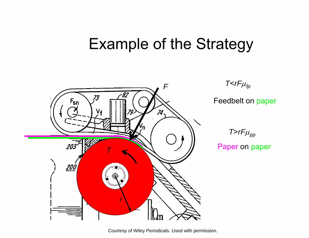
Single ArraysSingle Arrays
• Single arrays achieve improved run size economy or resolutioneconomy or resolution
• Focus on control by noise interactions which are essential for robust designessential for robust design
• “Some of the single arrays … are uniformly better than corresponding cross arrays in termsbetter than corresponding cross arrays in terms of the number of clear main effects and two factor interactions”factor interactions
• Example of a suggested design (Wu & Hamada)
210 5 210−5 A=1, B=2, C=3, D=4, E=234, F=134, G=123, a=5, b=124, c=1245

C te act o s
Comparing Crossed & Single ArraysComparing Crossed & Single Arrays
27 II− I 4 × 23
II− I 1 210−5
• 32 runs • 32 runs • All control factors • All control factors clear
aliased with CXC of 2fi •• All noise factors • All noise factors All noise factors • All noise factors
estimable estimable• 21 CxN interactions • 14 CxN interactions
clear of 2fi clear of 2fi clear of CxCxC clear of NxNxN

ResultsResults
Basic Fitted Method Experiments WH low 2nd WH low 2ndMethod Experiments WH low
w 2
order WH low
w 2
order 37 22 × 1,024 60% 81% 58% 50% 58% 40%
137 22 − 512 44% 80% 52% 45% 58% 40%137 22 × III 512 44% 80% 52% 45% 58% 40%4102 − 64 8% 8% 56% 18% 9% 38%
5102 − 32 9% 3% 33% 16% 9% 17%5102 − 32 9% 3% 33% 16% 9% 17%
1347 22 −− × IIIIII 32 12% 8% 51% 16% 25% 38% 132OFAT 32 39% 56% 43% 36% 42% 35%132 −× IIIOFAT 32 39% 56% 43% 36% 42% 35%
OFATOFAT × 32 31% 37% 41% 33% 31% 27% 6102 − 16 4% 4% 8% 4% 2% 0%2
the world assumed in classical DOE our data

What is Compound Noise?What is Compound Noise?
• Aggregate several noise factors into a single noise factorsingle noise factor
• Example – Temperature, humidity, salinity – Comppress 3D sppace
into a single axis
• RResollutition IIII outter array • Extreme conditions?
hot wet salty hot, wet, salty
cool, dry, fresh

⎟⎜⎟⎜
An Academic Perspective on Compound Noise
n Extreme settings exist iff β j ≥≥ ∑∑ γγ ijijβ j
i=1
The compound noise technique identifies the robust setting (that which minimizes variance) iff
m m⎛ ⎞⎛ ⎞ ⎜⎜∑β jγ ⎟⎟⎜⎜∑ sgn(ββ )γ ⎟⎟ >> 0, i = 11…ll ⎜∑β jγ ijij ⎜∑ sgn( jj )γ ijij ⎟ 0 i ⎝ j=1 ⎠
⎟⎝ j=1 ⎠
Hou, X. Shirley, 2002, “On the use of compound noise factor in parameter design experiments”, Applied Stochastic Models in Business and Industry 18:225-243.
•
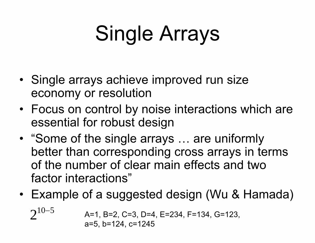
An Academic Perspective on Compound Noise
• Use of compound noise has been widespread
• Comppound noise techniqque can identifyy robust settings only in limited situations
• Their limited nature suggests they are not oftenTheir limited nature suggests they are not often satisfied in practical experiments
• The message from this study is that is thatThe message from this study is that is that compound noise technique does not perform very well in general situations very well in general situations
Hou, X. Shirley, 2002, “On the use of compound noise factor in parameter design experiments”, Applied Stochastic Models in Business and Industry 18:225-243.

t t
MethodMethod
• S lSelect a moddell off engiineeriing systems• Create 100 instances
– 7 control factors – 7 noise factors7 noise factors
• Run a full factorial inner array with – F ll f Full facttoriiall outter array – Compound noise outer array
• Plot and analyze results

=
Results with Locally Extreme CNResults with Locally Extreme CN
c = 100
A t th f
c 100 s = 3
Average strength of interactions ~0.25
Percent of possible reduction achieved ~80%
0 0.25 0.5 0.75 Possible reduction in standard deviation
1
~7% “success”
None had extreme settingssettings
1
0.75
d de
v
0.25
0.5
educ
tion
in st
d
0
Rea
lized
re
0.5
0.25

Streamlining Robust DesignStreamlining Robust Design
Singh, J., R. Jugulum, N. Soderborg, D. E. Whitney, and D. D. Frey, 2007, “Streamlining Robust Parameter Design Efforts,” Journal of Design Research 5(4):435-448.
1
0.9
0.8
0.7
0.6
0.5
0.4
0.3
0.2
0.1
00 0.2 0.4 0.6 0.8 1
Probability of an error in Pareto ordering
Frac
tion
of p
ossi
ble
bene
fits a
ttain
ed
No streamliningCompound noiseTake the Best fewFlowchart
Image by MIT OpenCourseWare.

MIT OpenCourseWarehttp://ocw.mit.edu
ESD.33 Systems Engineering Summer 2010
For information about citing these materials or our Terms of Use, visit: http://ocw.mit.edu/terms.