Embed Size (px)
Citation preview

(702) 636-2969(800) 497-1704
EZ LoaderOperation & Safety Manual
1415 W. Bonanza Rd. Las Vegas, NV 89106www.XtremeManufacturing.comMay 2020

For information call (800) 497-1704 Page 1
EZ Loader Table of Contents
Introduction . . . . . . . . . . . . . . . . . . . . . . . . . . . 2General . . . . . . . . . . . . . . . . . . . . . . . . . . . . . . 2Replacement Manuals . . . . . . . . . . . . . . . . . . . . . 2Orientation . . . . . . . . . . . . . . . . . . . . . . . . . . . . 2Vehicle Compliance . . . . . . . . . . . . . . . . . . . . . . 2Dealer Responsibility . . . . . . . . . . . . . . . . . . . . . . 3Delivery Report . . . . . . . . . . . . . . . . . . . . . . . . . 3Model/Serial Numbers . . . . . . . . . . . . . . . . . . . . . 3Nomenclature . . . . . . . . . . . . . . . . . . . . . . . . . . 4
Safety . . . . . . . . . . . . . . . . . . . . . . . . . . . . . . . 5Safety Disclaimer . . . . . . . . . . . . . . . . . . . . . . . . 5Signal Words . . . . . . . . . . . . . . . . . . . . . . . . . . . 5Safety Symbols . . . . . . . . . . . . . . . . . . . . . . . . . 5Employer Responsibility . . . . . . . . . . . . . . . . . . . 8Operator Responsibility . . . . . . . . . . . . . . . . . . . . 8Operator Qualification . . . . . . . . . . . . . . . . . . . . . 9Modifications . . . . . . . . . . . . . . . . . . . . . . . . . . 9Before Starting Vehicle . . . . . . . . . . . . . . . . . . . 10Operation Safety . . . . . . . . . . . . . . . . . . . . . . . 11Load Safety . . . . . . . . . . . . . . . . . . . . . . . . . . . 11Vehicle Maintenance . . . . . . . . . . . . . . . . . . . . 11Safety Equipment . . . . . . . . . . . . . . . . . . . . . . . 12Fire Extinguisher . . . . . . . . . . . . . . . . . . . . . . . 12First Aid Kit . . . . . . . . . . . . . . . . . . . . . . . . . . . 14Wheel Chocks . . . . . . . . . . . . . . . . . . . . . . . . . 14Chock Selection . . . . . . . . . . . . . . . . . . . . . . . . 14Chock Performance . . . . . . . . . . . . . . . . . . . . . 15Using Chocks . . . . . . . . . . . . . . . . . . . . . . . . . 15
Labels . . . . . . . . . . . . . . . . . . . . . . . . . . . . . . 16Replacement Labels . . . . . . . . . . . . . . . . . . . . . 16Label Legend . . . . . . . . . . . . . . . . . . . . . . . . . 1612M Labels . . . . . . . . . . . . . . . . . . . . . . . . . . . 1718M Labels . . . . . . . . . . . . . . . . . . . . . . . . . . . 1824M Labels . . . . . . . . . . . . . . . . . . . . . . . . . . . 19
Features . . . . . . . . . . . . . . . . . . . . . . . . . . . . . 20Standard Equipment . . . . . . . . . . . . . . . . . . . . . 20Optional Equipment . . . . . . . . . . . . . . . . . . . . . 20Specifications . . . . . . . . . . . . . . . . . . . . . . . . . 21
Pre-Operation Inspection. . . . . . . . . . . . . . . . . . 22Pre-Operation Inspection Checklist . . . . . . . . . . . 22
Controls . . . . . . . . . . . . . . . . . . . . . . . . . . . . . 23Flip Tail Control . . . . . . . . . . . . . . . . . . . . . . . . 23Dove Tail Control . . . . . . . . . . . . . . . . . . . . . . . 23Winch Control . . . . . . . . . . . . . . . . . . . . . . . . . 24Power Take Off (PTO) . . . . . . . . . . . . . . . . . . . . . 25
Operation . . . . . . . . . . . . . . . . . . . . . . . . . . . . 26Winch Operation . . . . . . . . . . . . . . . . . . . . . . . 26Extend Ramp . . . . . . . . . . . . . . . . . . . . . . . . . . 28Loading Operation . . . . . . . . . . . . . . . . . . . . . . 30
Unloading Operation . . . . . . . . . . . . . . . . . . . . 32Retract Ramp . . . . . . . . . . . . . . . . . . . . . . . . . 33
Preventive Maintenance . . . . . . . . . . . . . . . . . . 35Weekly Maintenance . . . . . . . . . . . . . . . . . . . . . 35Semi-Annual Maintenance . . . . . . . . . . . . . . . . . 35Replacing Oil and Filter . . . . . . . . . . . . . . . . . . . 35

Page 2 Xtreme Manufacturing, LLC
Introduction EZ Loader
Improper operation of the EZ Loader can causeinjury or death.BEFORE operating the EZ Loader, the operatormust do the following:• Read all Operator Manuals supplied with the
EZ Loader completely and carefully,understand all safety instructions, operationof controls, and safety equipment.
• Read all safety labels on the vehicle andtruck bed.
• Learn and practice safe use of EZ Loaderoperator controls in a safe, clear area.
You are responsible for observing all applicableFederal, State, and Local Laws and Regulationsand for following the manufacturer’s instructionsfor operation and maintenance of the EZ Loader.This information is provided for your benefit andyou must comply with all DANGER, WARNING,and CAUTION notices.
The EZ Loader is designed to streamline equipmentdelivery operations for any industry. The all-steelconstruction makes the EZ Loader an extremelydurable and valuable resource for transportingvehicles and equipment.
This Operator Manual provides importantinformation needed to safely operate the EZ Loader.This manual should be kept with all other vehicleoperator manuals and considered a permanent partof the EZ Loader.
Replacement manuals for the EZ Loader can beobtained by contacting:
Xtreme ManufacturingPhone: (800) 497-1704
Right side, left side, front, and rear are directionalreferences given from the operator’s seat whilefacing in a forward direction.
Figure 1-1. Vehicle Direction Orientation.
Federal law (49 CFR part 571) requires that theFinal Stage Manufacturer of a vehicle certify thatthe vehicle complies with all applicable federalregulations. Any modifications performed on thevehicle prior to the final stage are alsoconsidered intermediate stage manufacturingand must be certified as to compliance. Theinstaller of the EZ Loader and its components isconsidered one of the manufacturers of thisvehicle. As such a manufacturer, the installer isresponsible for compliance with all applicablefederal and state regulations, and is required tocertify that the vehicle is in compliance.
Vehicle Compliance
LEFT
RIGHTFRONT
REAR
XEZ-39
Orientation
Replacement Manuals
General
For information call (800) 497-1704 Page 3
EZ Loader Introduction
Your EZ Loader dealer is an important source ofinformation and assistance and is responsible for:
• Providing a complete delivery report within thespecified time frame required to comply with themanufacturer’s warranty.
• Explaining the capabilities and restrictions of theEZ Loader’s applications.
• Demonstrating the safe operation of theEZ Loader according to the instructionalmaterials, which should also be made available tothe operator.
• Identifying any unsafe modifications made to theEZ Loader.
For any questions regarding safety, operation, orcapacity of the truck, truck bed, and EZ Loader andfor specific information related to parts and serviceprocedures, contact:
Xtreme ManufacturingPhone: (800) 497-1704Fax: (702) 367-4134
NOTE: Some older models of the EZ Loader mayrequire different parts and service procedures.
Your EZ Loader dealer will review the delivery reportwith you.
The delivery report contains these items:
• Affidavit of Purchaser• Affidavit of None Operation• Weight Certificate• Title or Manufacturers Statement of Origin (MSO)• Odometer Statement• Operation and Maintenance Manual(s)
For easy reference record the vehicle identificationnumber, model, and serial number in the spaceprovided.
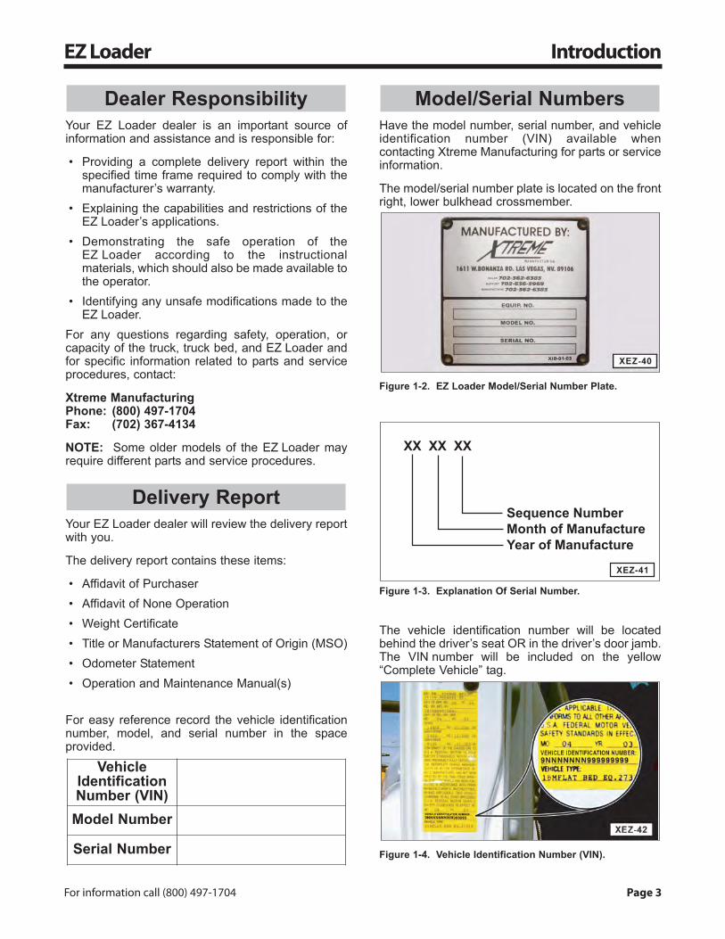
Have the model number, serial number, and vehicleidentification number (VIN) available whencontacting Xtreme Manufacturing for parts or serviceinformation.
The model/serial number plate is located on the frontright, lower bulkhead crossmember.
Figure 1-2. EZ Loader Model/Serial Number Plate.
Figure 1-3. Explanation Of Serial Number.
The vehicle identification number will be locatedbehind the driver’s seat OR in the driver’s door jamb.The VIN number will be included on the yellow“Complete Vehicle” tag.
Figure 1-4. Vehicle Identification Number (VIN).
XX XX XX
Sequence NumberMonth of ManufactureYear of Manufacture
XEZ-41
Model/Serial Numbers
VehicleIdentificationNumber (VIN)
Model Number
Serial Number
Delivery Report
Dealer Responsibility
Page 4 Xtreme Manufacturing, LLC
Introduction EZ Loader
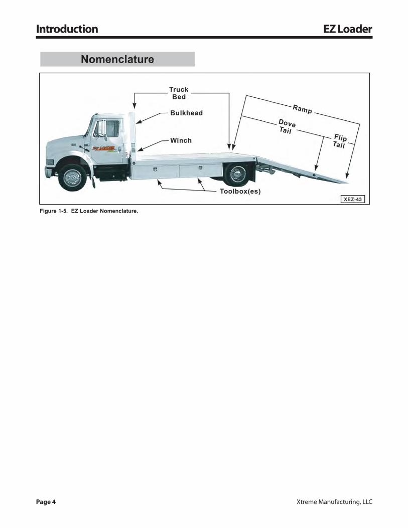
Figure 1-5. EZ Loader Nomenclature.
Nomenclature
For information call (800) 497-1704 Page 5
EZ Loader Safety
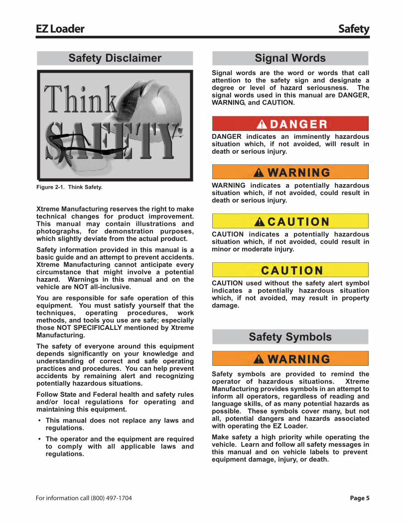
Figure 2-1. Think Safety.
Xtreme Manufacturing reserves the right to maketechnical changes for product improvement.This manual may contain illustrations andphotographs, for demonstration purposes,which slightly deviate from the actual product.Safety information provided in this manual is abasic guide and an attempt to prevent accidents.Xtreme Manufacturing cannot anticipate everycircumstance that might involve a potentialhazard. Warnings in this manual and on thevehicle are NOT all-inclusive.You are responsible for safe operation of thisequipment. You must satisfy yourself that thetechniques, operating procedures, workmethods, and tools you use are safe; especiallythose NOT SPECIFICALLY mentioned by XtremeManufacturing.The safety of everyone around this equipmentdepends significantly on your knowledge andunderstanding of correct and safe operatingpractices and procedures. You can help preventaccidents by remaining alert and recognizingpotentially hazardous situations.Follow State and Federal health and safety rulesand/or local regulations for operating andmaintaining this equipment.• This manual does not replace any laws and
regulations.• The operator and the equipment are required
to comply with all applicable laws andregulations.
Signal words are the word or words that callattention to the safety sign and designate adegree or level of hazard seriousness. Thesignal words used in this manual are DANGER,WARNING, and CAUTION.
DANGER indicates an imminently hazardoussituation which, if not avoided, will result indeath or serious injury.
WARNING indicates a potentially hazardoussituation which, if not avoided, could result indeath or serious injury.
CAUTION indicates a potentially hazardoussituation which, if not avoided, could result inminor or moderate injury.
CAUTION used without the safety alert symbolindicates a potentially hazardous situationwhich, if not avoided, may result in propertydamage.
Safety symbols are provided to remind theoperator of hazardous situations. XtremeManufacturing provides symbols in an attempt toinform all operators, regardless of reading andlanguage skills, of as many potential hazards aspossible. These symbols cover many, but notall, potential dangers and hazards associatedwith operating the EZ Loader.Make safety a high priority while operating thevehicle. Learn and follow all safety messages inthis manual and on vehicle labels to preventequipment damage, injury, or death.
Safety Symbols
Signal WordsSafety Disclaimer

Page 6 Xtreme Manufacturing, LLC
Safety EZ Loader
Set ParkingBrake To OFF
DisengageParking Brake
Set ParkingBrake To ON
EngageParking Brake
DO NOT AllowRiders On TheOperator Cab
DO NOT AllowRiders On
Vehicle FrameOr Fenders
FastenSeatBelt
Replace WornAnd Illegible
Safety DecalsAnd Labels
Make Sure AllSafety DecalsAre AttachedAnd Legible
Hot Oil!DO NOT OpenUnless Cap IsCool To Touch
HydraulicSystem Under
Pressure
Use A Board OrCardboard To
Check HydraulicLeaks. DO NOTUse Your Hand!
Warning!Hydraulic Oil
Under Pressure
Keep FlamesAnd Ignition
Sources Away
No SmokingKeep Lit
CigarettesAway
Lead AcidBatteries CreateExplosive Gases
PersonalProtectiveEquipment
Ear Protectors
PersonalProtectiveEquipment
Safety Glasses
PersonalProtectiveEquipment
Safety Shoes
PersonalProtectiveEquipment
Gloves
PersonalProtectiveEquipment
Hardhat
DO NOT OperateIf Using
Alcohol, Drugs,Or Medications
Know First AidInstructions
And/OrLocations On
Worksite
Read MaterialSafety Data
Sheets (MSDS)For Chemicals
And Fluids
PerformOperator
InspectionBefore Starting
This Vehicle
ReadMaintenance
Manual BeforeWorking OnThis Vehicle
Read OperatorManual BeforeOperating This
Vehicle
General SafetyAlert Symbol
For information call (800) 497-1704 Page 7
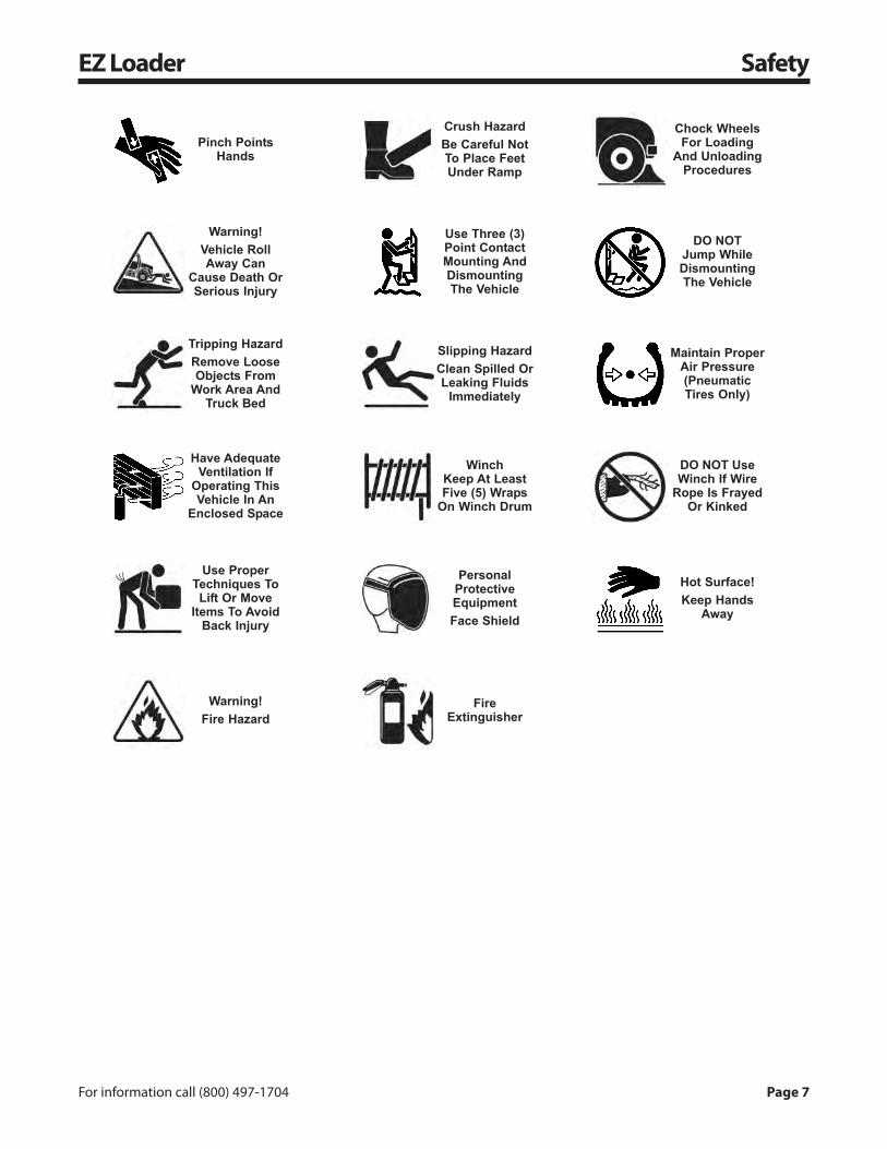
EZ Loader Safety
FireExtinguisher
Warning!Fire Hazard
Hot Surface!Keep Hands
Away
PersonalProtectiveEquipmentFace Shield
Use ProperTechniques ToLift Or Move
Items To AvoidBack Injury
DO NOT UseWinch If Wire
Rope Is FrayedOr Kinked
WinchKeep At LeastFive (5) Wraps
On Winch Drum
Have AdequateVentilation If
Operating ThisVehicle In An
Enclosed Space
Maintain ProperAir Pressure(PneumaticTires Only)
Slipping HazardClean Spilled OrLeaking Fluids
Immediately
Tripping HazardRemove LooseObjects From
Work Area AndTruck Bed
DO NOTJump WhileDismountingThe Vehicle
Use Three (3)Point ContactMounting AndDismountingThe Vehicle
Warning!Vehicle RollAway Can
Cause Death OrSerious Injury
Chock WheelsFor Loading
And UnloadingProcedures
Crush HazardBe Careful NotTo Place FeetUnder Ramp
Pinch PointsHands

Page 8 Xtreme Manufacturing, LLC
Safety EZ Loader
Under OSHA rules, employers are required totrain workers about hazards related to operatingand maintaining the EZ Loader.Operator trainees must remain under constantobservation and supervision of an experiencedoperator.An untrained operator can unknowingly create adangerous situation which can result in theinjury or death of the operator and others.Only allow trained, qualified, and authorizedpersonnel to operate the EZ Loader withoutsupervision.Safety and training information can be obtainedthrough these publications, organizations,and/or other appropriate sources:• Code of Federal Regulations (29 CFR)• Occupational Safety and Health Administration
(OSHA)• National Institute for Occupational Health and
Safety (NIOSH)• American National Standards Institute (ANSI)• Association of Equipment Manufacturers
(AEM)• American Society of Mechanical Engineers
(ASME) (including ASME B30.7, B30.9)• National Fire Protection Association, Inc.
(NFPA Standard #10)• Department of Transportation (DOT)• National Safety Council, Accident Prevention
Manual for Industrial Operations• Federal Motor Carriers Safety Regulations
(FMCSR 392.7)Always consult Material Safety Data Sheets(MSDS) for chemical hazards and first aidinstructions for any oil or lubricant being used.MSDS should be available from the manufactureror supplier of the fluid.
The EZ Loader is potentially dangerous if propersafety procedures are not followed. Workerswho operate, maintain, or work near theEZ Loader can be at risk of roll over and run overincidents. Workers can be crushed or caught bythe EZ Loader or its parts if it is not operated ormaintained properly.
Read all Operator Manualsbefore operating theEZ Loader. Only operatethe vehicle if youunderstand the safety
instructions and warnings in all applicablemanuals and technical publications. Follow allsafety instructions, labels, and all State andFederal health and safety laws and/or localregulations.You must have the required training, skills, andtools to perform installation, operation,maintenance, or repair procedures properly andsafely. Make sure the EZ Loader will not bedamaged or made unsafe by any procedures youchoose.Make sure the EZ Loader meets all local, state,and federal regulations; including, but notlimited to those required for bumpers, lighting,and reflectors.DO NOT allow untrained personnel or children toplay around or operate the EZ Loader.You are responsible for safe operation of thewinch. Exercise caution, use common sense,and be familiar with safe rigging techniques.Refer to applicable industry standards forrigging techniques, including ASME B30.9 forrigging information, American NationalStandards Institute, 1430 Broadway, New York,NY 10018.DO NOT use this equipment for any otherpurpose than what it was designed for andrefuse to operate any equipment that showssigns of abuse, damage, fails to operate freelyand smoothly, or has “DO NOT OPERATE” tagsattached to it.
Operator ResponsibilityEmployer Responsibility
For information call (800) 497-1704 Page 9
EZ Loader Safety
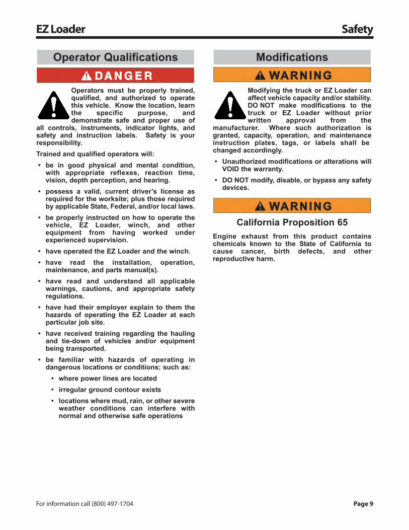
Operators must be properly trained,qualified, and authorized to operatethis vehicle. Know the location, learnthe specific purpose, anddemonstrate safe and proper use of
all controls, instruments, indicator lights, andsafety and instruction labels. Safety is yourresponsibility.Trained and qualified operators will:• be in good physical and mental condition,
with appropriate reflexes, reaction time,vision, depth perception, and hearing.
• possess a valid, current driver’s license asrequired for the worksite; plus those requiredby applicable State, Federal, and/or local laws.
• be properly instructed on how to operate thevehicle, EZ Loader, winch, and otherequipment from having worked underexperienced supervision.
• have operated the EZ Loader and the winch.• have read the installation, operation,
maintenance, and parts manual(s).• have read and understand all applicable
warnings, cautions, and appropriate safetyregulations.
• have had their employer explain to them thehazards of operating the EZ Loader at eachparticular job site.
• have received training regarding the haulingand tie-down of vehicles and/or equipmentbeing transported.
• be familiar with hazards of operating indangerous locations or conditions; such as:
• where power lines are located• irregular ground contour exists• locations where mud, rain, or other severe
weather conditions can interfere withnormal and otherwise safe operations
Modifying the truck or EZ Loader canaffect vehicle capacity and/or stability.DO NOT make modifications to thetruck or EZ Loader without priorwritten approval from the
manufacturer. Where such authorization isgranted, capacity, operation, and maintenanceinstruction plates, tags, or labels shall bechanged accordingly.• Unauthorized modifications or alterations will
VOID the warranty.• DO NOT modify, disable, or bypass any safety
devices.
California Proposition 65Engine exhaust from this product containschemicals known to the State of California tocause cancer, birth defects, and otherreproductive harm.
ModificationsOperator Qualifications
Page 10 Xtreme Manufacturing, LLC
Safety EZ Loader
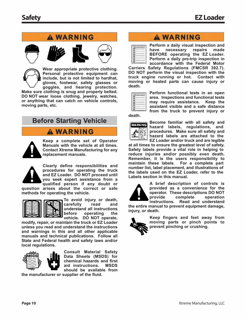
Wear appropriate protective clothing.Personal protective equipment caninclude, but is not limited to hardhat,gloves, footwear, safety glasses orgoggles, and hearing protection.
Make sure clothing is snug and properly belted.DO NOT wear loose clothing, jewelry, watches,or anything that can catch on vehicle controls,moving parts, etc.
Keep a complete set of OperatorManuals with the vehicle at all times.Contact Xtreme Manufacturing for anyreplacement manuals.
Clearly define responsibilities andprocedures for operating the truckand EZ Loader. DO NOT proceed untilyou seek expert assistance from aqualified person if any doubt or
question arises about the correct or safemethods for operating the vehicle.
To avoid injury or death,carefully read andunderstand all instructionsbefore operating thevehicle. DO NOT operate,
modify, repair, or maintain the truck or EZ Loaderunless you read and understand the instructionsand warnings in this and all other applicablemanuals and technical publications. Follow allState and Federal health and safety laws and/orlocal regulations.
Consult Material SafetyData Sheets (MSDS) forchemical hazards and firstaid instructions. MSDSshould be available from
the manufacturer or supplier of the fluid.
Perform a daily visual inspection andhave necessary repairs madeBEFORE operating the EZ Loader.Perform a daily pre-trip inspection inaccordance with the Federal Motor
Carriers Safety Regulations (FMCSR 392.7).DO NOT perform the visual inspection with thetruck engine running or hot. Contact withmoving or heated parts can cause injury ordeath.
Perform functional tests in an openarea. Inspections and functional testsmay require assistance. Keep theassistant visible and a safe distancefrom the truck to prevent injury or
death.Become familiar with all safety andhazard labels, regulations, andprocedures. Make sure all safety andhazard labels are attached to theEZ Loader and/or truck and are legible
at all times to ensure the greatest level of safety.Safety labels provide a vital role in helping toreduce injuries and/or possibly even death.Remember, it is the users responsibility tomaintain these labels. For a complete partnumber list, label placement, and illustrations ofthe labels used on the EZ Loader, refer to theLabels section in this manual.
A brief description of controls isprovided as a convenience for theoperator. These descriptions DO NOTprovide complete operationinstructions. Read and understand
the entire manual to prevent equipment damage,injury, or death.
Keep fingers and feet away frommoving parts or pinch points toprevent pinching or crushing.
Before Starting Vehicle
For information call (800) 497-1704 Page 11
EZ Loader Safety
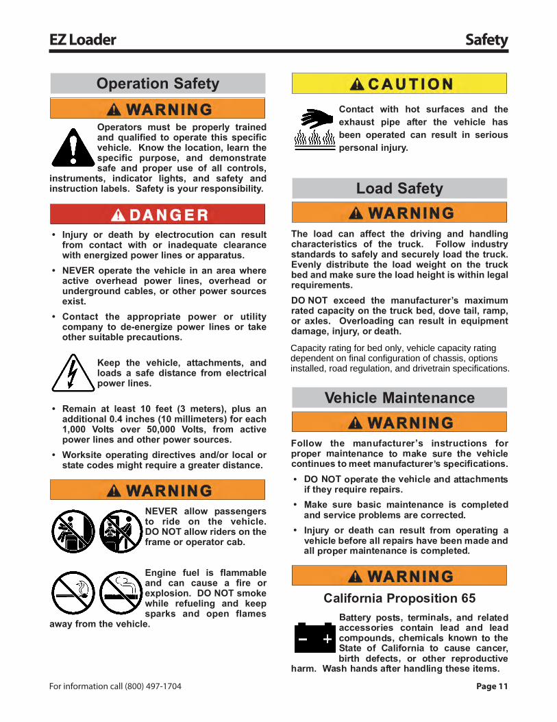
Operators must be properly trainedand qualified to operate this specificvehicle. Know the location, learn thespecific purpose, and demonstratesafe and proper use of all controls,
instruments, indicator lights, and safety andinstruction labels. Safety is your responsibility.
• Injury or death by electrocution can resultfrom contact with or inadequate clearancewith energized power lines or apparatus.
• NEVER operate the vehicle in an area whereactive overhead power lines, overhead orunderground cables, or other power sourcesexist.
• Contact the appropriate power or utilitycompany to de-energize power lines or takeother suitable precautions.
Keep the vehicle, attachments, andloads a safe distance from electricalpower lines.
• Remain at least 10 feet (3 meters), plus anadditional 0.4 inches (10 millimeters) for each1,000 Volts over 50,000 Volts, from activepower lines and other power sources.
• Worksite operating directives and/or local orstate codes might require a greater distance.
NEVER allow passengersto ride on the vehicle.DO NOT allow riders on theframe or operator cab.
Engine fuel is flammableand can cause a fire orexplosion. DO NOT smokewhile refueling and keepsparks and open flames
away from the vehicle.
Contact with hot surfaces and theexhaust pipe after the vehicle hasbeen operated can result in seriouspersonal injury.
The load can affect the driving and handling characteristics of the truck. Follow industry standards to safely and securely load the truck. Evenly distribute the load weight on the truck bed and make sure the load height is within legal requirements.DO NOT exceed the manufacturer’s maximum rated capacity on the truck bed, dove tail, ramp, or axles. Overloading can result in equipment damage, injury, or death.
Follow the manufacturer’s instructions forproper maintenance to make sure the vehiclecontinues to meet manufacturer’s specifications.• DO NOT operate the vehicle and attachments
if they require repairs.• Make sure basic maintenance is completed
and service problems are corrected.• Injury or death can result from operating a
vehicle before all repairs have been made andall proper maintenance is completed.
California Proposition 65Battery posts, terminals, and relatedaccessories contain lead and leadcompounds, chemicals known to theState of California to cause cancer,birth defects, or other reproductive
harm. Wash hands after handling these items.
Vehicle Maintenance
Load Safety
Operation Safety
Capacity rating for bed only, vehicle capacity rating dependent on final configuration of chassis, options installed, road regulation, and drivetrain specifications.
Page 12 Xtreme Manufacturing, LLC
Safety EZ Loader
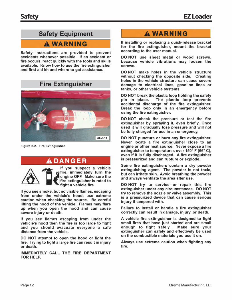
Safety instructions are provided to preventaccidents whenever possible. If an accident orfire occurs, react quickly with the tools and skillsavailable. Know how to use the fire extinguisherand first aid kit and where to get assistance.
Figure 2-2. Fire Extinguisher.
If you suspect a vehiclefire, immediately turn theengine OFF. Make sure thefire extinguisher is rated tofight a vehicle fire.
If you see smoke, but no visible flames, escapingfrom under the vehicle’s hood; use extremecaution when checking the source. Be carefullifting the hood of the vehicle. Flames may flareup when you open the hood and can causesevere injury or death.If you see flames escaping from under thevehicle’s hood then the fire is too large to fightand you should evacuate everyone a safedistance from the vehicle.DO NOT attempt to open the hood or fight thefire. Trying to fight a large fire can result in injuryor death.IMMEDIATELY CALL THE FIRE DEPARTMENTFOR HELP.
If installing or replacing a quick-release bracketfor the fire extinguisher, mount the bracketaccording to the user manual.DO NOT use sheet metal or wood screws,because vehicle vibrations may loosen thescrews.DO NOT make holes in the vehicle structurewithout checking the opposite side. Creatingholes in the vehicle structure can cause severedamage to electrical lines, gasoline lines ortanks, or other vehicle systems.DO NOT break the plastic loop holding the safetypin in place. The plastic loop preventsaccidental discharge of the fire extinguisher.Break the loop only in an emergency beforeusing the fire extinguisher.DO NOT check the pressure or test the fireextinguisher by spraying it, even briefly. Onceused it will gradually lose pressure and will notbe fully charged for use in an emergency.DO NOT puncture or burn any fire extinguisher.Never locate a fire extinguisher close to anengine or other heat source. Never expose a fireextinguisher to temperatures over 150° F (66° C),even if it is fully discharged. A fire extinguisheris pressurized and can rupture or explode.Some fire extinguishers contain a dry powderextinguishing agent. The powder is not toxic,but can irritate skin. Avoid breathing the powderand always ventilate the area after use.DO NOT try to service or repair this fireextinguisher under any circumstances. DO NOTtry to remove the nozzle or valve assembly. Thisis a pressurized device that can cause seriousinjury if tampered with.Failure to install or handle a fire extinguishercorrectly can result in damage, injury, or death.A vehicle fire extinguisher is designed to fightsmall fires that have just started and are smallenough to fight safely. Make sure yourextinguisher can safely and effectively be usedon the combustible materials you use it on.Always use extreme caution when fighting anyfire.
Fire Extinguisher
Safety Equipment

For information call (800) 497-1704 Page 13
EZ Loader Safety
Fight a fire only where there is a clear escapepath that allows you to get away safely if the firegets worse.Always remain far enough away from the fire andmake sure nothing is between you and anescape route.If you get too close to a fire, you risk gettingburned or hit by splattering material like oil orgrease.DO NOT try to fight a fire that is too hot or smokyto get within 6 feet (2 meters) of. A vehicle fireextinguisher is not designed to fight large firesthat are burning out of control. Warn everyone,evacuate the area, and call the Fire Department asafe distance from the vehicle.Trying to fight a large fire yourself can result ininjury or death.Fight the fire from an upwind direction with yourback to any strong air current. Fighting a firewith the wind blowing towards you can result ininjury or death.Avoid breathing smoke and heated fumes andstay low, if necessary. Burning materials willrelease toxic fumes which can result in injury ordeath.If a vehicle has started on fire and the fire hasbeen extinguished, DO NOT start the vehicle orplug in any electrical accessories (cellularphone, CD player, etc.) until the vehicle has beenthoroughly and completely cleaned. Failure toremove the powder from electrical equipmentcan create a hazardous situation. If the powdergets wet, it can conduct electricity. This mayworsen an electrical leakage problem, impair theequipment’s insulation, or create an electricalshock hazard.Using a dry chemical extinguisher on wetelectrical equipment can be hazardous, becauseit can conduct electricity if the powder gets wet,resulting in electrocution.
Read the fire extinguisher’s user manual and labelcarefully and keep it with the vehicle. Review theuser manual regularly because it contains importantinformation about operating the fire extinguisher andin an emergency you will not have time to read theinstructions.
Fire extinguishers are classified by fire type. The fireextinguisher rating system (A, B, and C) defines theburning materials a fire extinguisher is designed tofight.
• Class A: This fire extinguisher is suitable forfighting small fires involving wood, paper,cloth, rubber, and some plastics.
• Class B: This fire extinguisher is suitable forfighting small fires involving grease, gasoline,oil, kerosene, and other flammable liquids.
• Class C: This fire extinguisher is suitable forfighting small fires involving "live" electricalequipment.
The numbers in front of the rating indicate the size offire the fire extinguisher is useful for.
NOTE: Make sure the extinguisher is rated to fightthe type of fire most likely to occur in or around thevehicle. Make sure you understand which fireextinguisher to use on each class of fire. Using thewrong type of fire extinguisher can do more harmthan good.
NOTE: Additional information on fire extinguisherscan be obtained from the National Fire ProtectionAssociation Standard Number 10, “Portable FireExtinguishers,” available from the National FireProtection Association, Inc., Batterymarch Park,Quincy, MA 02169, USA.
Page 14 Xtreme Manufacturing, LLC
Safety EZ Loader
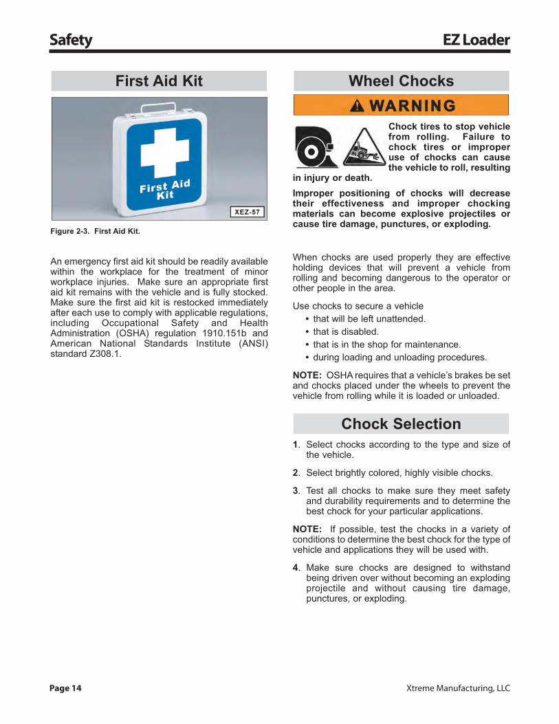
Figure 2-3. First Aid Kit.
An emergency first aid kit should be readily availablewithin the workplace for the treatment of minorworkplace injuries. Make sure an appropriate firstaid kit remains with the vehicle and is fully stocked.Make sure the first aid kit is restocked immediatelyafter each use to comply with applicable regulations,including Occupational Safety and HealthAdministration (OSHA) regulation 1910.151b andAmerican National Standards Institute (ANSI)standard Z308.1.
Chock tires to stop vehiclefrom rolling. Failure tochock tires or improperuse of chocks can causethe vehicle to roll, resulting
in injury or death.Improper positioning of chocks will decreasetheir effectiveness and improper chockingmaterials can become explosive projectiles orcause tire damage, punctures, or exploding.
When chocks are used properly they are effectiveholding devices that will prevent a vehicle fromrolling and becoming dangerous to the operator orother people in the area.
Use chocks to secure a vehicle• that will be left unattended.• that is disabled.• that is in the shop for maintenance.• during loading and unloading procedures.
NOTE: OSHA requires that a vehicle’s brakes be setand chocks placed under the wheels to prevent thevehicle from rolling while it is loaded or unloaded.
1. Select chocks according to the type and size ofthe vehicle.
2. Select brightly colored, highly visible chocks.
3. Test all chocks to make sure they meet safetyand durability requirements and to determine thebest chock for your particular applications.
NOTE: If possible, test the chocks in a variety ofconditions to determine the best chock for the type ofvehicle and applications they will be used with.
4. Make sure chocks are designed to withstandbeing driven over without becoming an explodingprojectile and without causing tire damage,punctures, or exploding.
Chock Selection
Wheel ChocksFirst Aid Kit

For information call (800) 497-1704 Page 15
EZ Loader Safety
Many factors can affect the performance of chocks,including:
• gross vehicle weight• road conditions (i.e. firm, soft, wet, dry, icy)• tire size• tire pressure• type of tire
NOTE: Radial tires are designed to deflect morethan bias-ply tires to provide a smooth, comfortableride, however, this factor allows radial tires to wraparound a chock and makes the chock less effective.
1. Make sure the vehicle is parked on a firm, levelsurface.
2. Apply the parking brake and test how well it isholding before placing wheel chocks.
3. Always use chocks in pairs.
4. Chock the vehicle’s wheels in the direction of thegrade.a. Position chocks downhill, below the
vehicle’s center of gravity.b. Chock in front of the wheels if the vehicle is
facing down a grade.c. Chock behind the wheels if the vehicle is
facing up a grade.d. Chock in front of and behind the wheels if
the vehicle is on a level surface or if thedirection of the grade is undetermined.
5. Center chocks square and snug against the treadof each tire.
6. DO NOT drive over chocks.
7. Inspect chocks periodically for cracking, chipping,or other signs of damage.
NOTE: Improper positioning of wheel chocks willdecrease their effectiveness.
Using Chocks
Chock Performance
Page 16 Xtreme Manufacturing, LLC
Labels EZ Loader
Replacement labels can be obtained by contactingXtreme Manufacturing at (800) 497-1704. Pleasehave the appropriate label number available whenyou call.
Become familiar with all safety andhazard labels, regulations, andprocedures. Make sure all safety andhazard labels are attached to theEZ Loader and/or truck and are legible
at all times to ensure the greatest level of safety.Safety labels provide a vital role in helping toreduce injuries and/or possibly even death.Remember, it is the users responsibility tomaintain these labels.
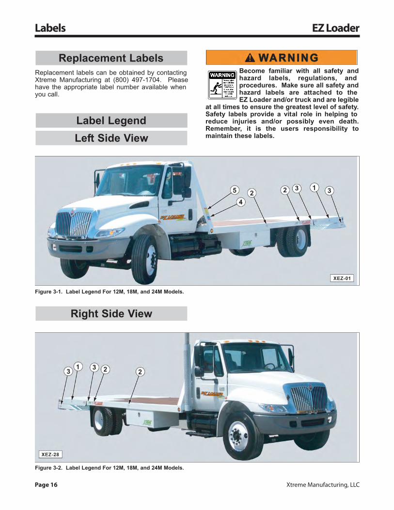
Right Side View
Left Side ViewLabel Legend
Replacement Labels
Figure 3-2. Label Legend For 12M, 18M, and 24M Models.
Figure 3-1. Label Legend For 12M, 18M, and 24M Models.
For information call (800) 497-1704 Page 17
EZ Loader Labels
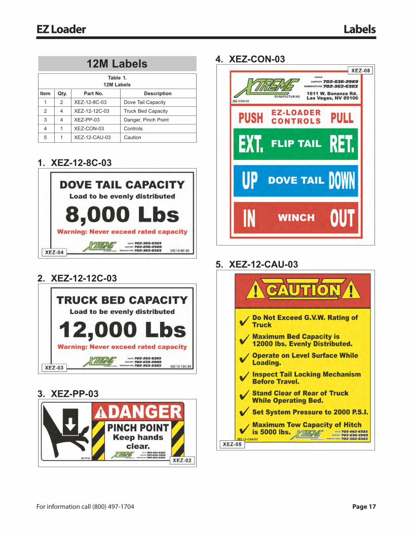
1. XEZ-12-8C-03
2. XEZ-12-12C-03
3. XEZ-PP-03
4. XEZ-CON-03
5. XEZ-12-CAU-03
Table .12M Labels
Item Qty. Part No. Description
1 2 XEZ-12-8C-03 Dove Tail Capacity
2 4 XEZ-12-12C-03 Truck Bed Capacity
3 4 XEZ-PP-03 Danger, Pinch Point
4 1 XEZ-CON-03 Controls
5 1 XEZ-12-CAU-03 Caution
12M Labels1

Page 18 Xtreme Manufacturing, LLC
Labels EZ Loader
1. XEZ-18-10C-03
2. XEZ-18-18C-03
3. XEZ-PP-03
4. XEZ-CON-03
5. XEZ-18-CAU-03
Table .18M Labels
Item Qty. Part No. Description
1 2 XEZ-18-10C-03 Dove Tail Capacity
2 4 XEZ-18-18C-03 Truck Bed Capacity
3 4 XEZ-PP-03 Danger, Pinch Point
4 1 XEZ-CON-03 Controls
5 1 XEZ-18-CAU-03 Caution
18M Labels2
For information call (800) 497-1704 Page 19
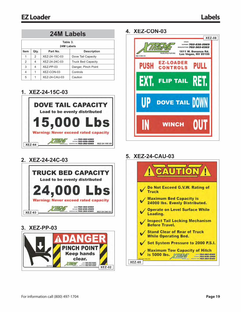
EZ Loader Labels
1. XEZ-24-15C-03
2. XEZ-24-24C-03
3. XEZ-PP-03
4. XEZ-CON-03
5. XEZ-24-CAU-03
Table .24M Labels
Item Qty. Part No. Description
1 2 XEZ-24-15C-03 Dove Tail Capacity
2 4 XEZ-24-24C-03 Truck Bed Capacity
3 4 XEZ-PP-03 Danger, Pinch Point
4 1 XEZ-CON-03 Controls
5 1 XEZ-24-CAU-03 Caution
24M Labels3

Page 20 Xtreme Manufacturing, LLC
Features EZ Loader
Table .EZ Loader Optional Equipment
Description Feature
Bed Options 1/4 or 1/16 inch polished aluminum diamondplate on bulkhead
Chain and binder rack (locking)
Loading light bar (12 Volt)
Stake racks
Truck Options Air seat (driver side only)
Air brakes
Alcoa aluminum wheels or chrome wheelcovers
Allison automatic transmission
Locking differential
Tilt and telescopic steering wheel
Split bench seat
Special paint/pin striping
Tool Box Options 48 x 30 x 17 in (1219.2 x 762.0 x 431.8 mm)
(W x D x H) 96 x 30 x 17 in (2438.4 x 762.0 x 431.8 mm)
Optional Equipment
Table .EZ Loader Standard Equipment
Description Feature
Bulkhead Bolted to frame, welded to bed
Ramp Traction plate
Chain Boxes
Tie Downs Nylon strapChain
Ramp Knife edge
Positive Tail Lock Non-hydraulic
Winch Hydraulic, 9,000 lb (4082 kg) CapacityHydraulic, 12,000 lb (5443 kg) CapacityTension Kit included
Standard Equipment4
5
For information call (800) 497-1704 Page 21
EZ Loader Features
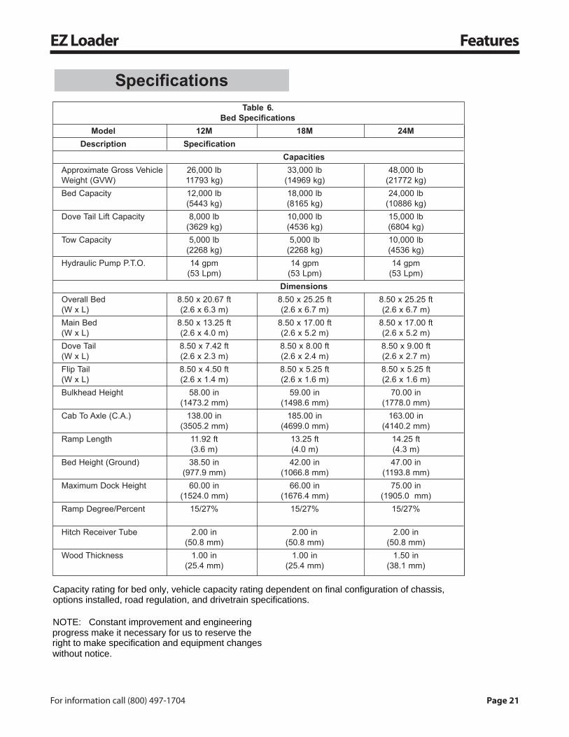
SpecificationsTable .
Bed SpecificationsModel 12M 18M 24M
Description SpecificationCapacities
Approximate Gross Vehicle 26,000 lb 33,000 lb 48,000 lbWeight (GVW) 11793 kg) (14969 kg) (21772 kg)Bed Capacity 12,000 lb 18,000 lb 24,000 lb
(5443 kg) (8165 kg) (10886 kg)Dove Tail Lift Capacity 8,000 lb 10,000 lb 15,000 lb
(3629 kg) (4536 kg) (6804 kg)Tow Capacity 5,000 lb 5,000 lb 10,000 lb
(2268 kg) (2268 kg) (4536 kg)Hydraulic Pump P.T.O. 14 gpm 14 gpm 14 gpm
(53 Lpm) (53 Lpm) (53 Lpm)Dimensions
Overall Bed 8.50 x 20.67 ft 8.50 x 25.25 ft 8.50 x 25.25 ft(W x L) (2.6 x 6.3 m) (2.6 x 6.7 m) (2.6 x 6.7 m)Main Bed 8.50 x 13.25 ft 8.50 x 17.00 ft 8.50 x 17.00 ft(W x L) (2.6 x 4.0 m) (2.6 x 5.2 m) (2.6 x 5.2 m)Dove Tail 8.50 x 7.42 ft 8.50 x 8.00 ft 8.50 x 9.00 ft(W x L) (2.6 x 2.3 m) (2.6 x 2.4 m) (2.6 x 2.7 m)Flip Tail 8.50 x 4.50 ft 8.50 x 5.25 ft 8.50 x 5.25 ft(W x L) (2.6 x 1.4 m) (2.6 x 1.6 m) (2.6 x 1.6 m)Bulkhead Height 58.00 in 59.00 in 70.00 in
(1473.2 mm) (1498.6 mm) (1778.0 mm)Cab To Axle (C.A.) 138.00 in 185.00 in 163.00 in
(3505.2 mm) (4699.0 mm) (4140.2 mm)Ramp Length 11.92 ft 13.25 ft 14.25 ft
(3.6 m) (4.0 m) (4.3 m)Bed Height (Ground) 38.50 in 42.00 in 47.00 in
(977.9 mm) (1066.8 mm) (1193.8 mm)Maximum Dock Height 60.00 in 66.00 in 75.00 in
(1524.0 mm) (1676.4 mm) (1905.0 mm)Ramp Degree/Percent 15/27% 15/27% 15/27%
Hitch Receiver Tube 2.00 in 2.00 in 2.00 in(50.8 mm) (50.8 mm) (50.8 mm)
Wood Thickness 1.00 in 1.00 in 1.50 in(25.4 mm) (25.4 mm) (38.1 mm)
6
Capacity rating for bed only, vehicle capacity rating dependent on final configuration of chassis, options installed, road regulation, and drivetrain specifications.
NOTE: Constant improvement and engineering progress make it necessary for us to reserve the right to make specification and equipment changes without notice.

Page 22 Xtreme Manufacturing, LLC
Pre-Operation Inspection EZ Loader
Perform a daily visual inspection andhave necessary repairs made beforeoperating the EZ Loader.Perform a daily pre-trip inspection inaccordance with the Federal Motor
Carriers Safety Regulations (FMCSR 392.7).DO NOT perform the visual inspection with thetruck engine running or hot. Contact withmoving or heated parts can cause injury ordeath.
Perform functional tests in an openarea. Inspections and functional testsmay require assistance. Keep theassistant visible and a safe distancefrom the truck to prevent injury or
death.
Walk around the ENTIRE vehicle while visually performing the pre-operation inspection.
Check that “Do Not Operate” tags have not been placed on the vehicle or equipment.Check that all Operator Manuals are in the vehicle and legible.Check engine compartment for:
Damaged belts, hoses, and radiator blades.Coolant reservoir level. Add radiator coolant, if necessary.Engine oil level. Add engine oil, if necessary.Electrical wires and connectors.
Check battery for:Corrosion on terminals.Cracked, melted, or damaged case.
Check all hydraulic hoses and hose connections for wear or leaks. Use a piece of cardboard.Check hydraulic sight gauge for proper fluid level. The sight glass should show 3/4 full at all times.Add hydraulic fluid, if necessary.Check all tires, rims, and wheels for:
Punctures, cracks, cuts, gouges, bulges, foreign objects, or any other damage to tires.Correct pressure (pneumatic tires only).Loose or missing lug nuts.Bent flanges or any other damage to rims.
Check front and rear axles for leaks or any other damage.Check that all labels and stickers are legible. Replace any damaged or illegible stickers.Check mirrors for cracks, cleanliness, and proper adjustment.
Date: Initials:
Pre-Operation Inspection Checklist

For information call (800) 497-1704 Page 23
EZ Loader Controls
A brief description of controls isprovided as a convenience for theoperator. These descriptions DO NOTprovide complete operationinstructions. Read and understand
the entire manual to prevent equipment damage,injury, or death.
The flip tail control lever activates a single hydrauliccylinder which extends and retracts the flip tail of theEZ Loader and releases or engages the lockingmechanism.
Figure 6-1. Flip Tail Control Lever.(A) Push To Extend Flip Tail. (B) Pull To Retract Flip Tail.
Figure 6-2. Flip Tail Extend (A) And Flip Tail Retract (B).
Figure 6-3. Flip Tail Control Lever Engages And DisengagesLocking Mechanism.
Figure 6-4. Flip Tail Hydraulic Cylinder.
The dove tail control lever activates two (2) hydrauliccylinders which raise and lower the dove tail and,when the flip tail is extended, controls the ramp.
Figure 6-5. Dove Tail Control Lever.(A) Push To Raise Dove Tail Or Ramp Up. (B) Pull To LowerDove Tail Or Ramp Down.
Dove Tail Control
Flip Tail Control
Page 24 Xtreme Manufacturing, LLC
Controls EZ Loader
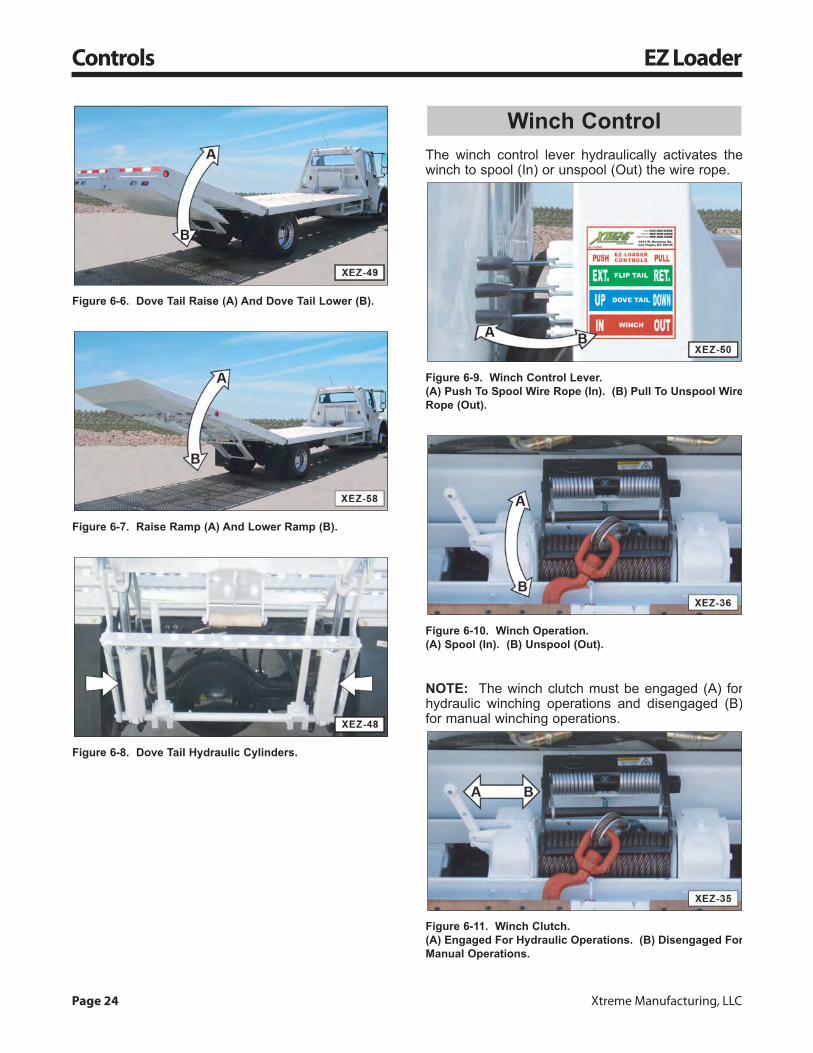
Figure 6-6. Dove Tail Raise (A) And Dove Tail Lower (B).
Figure 6-7. Raise Ramp (A) And Lower Ramp (B).
Figure 6-8. Dove Tail Hydraulic Cylinders.
The winch control lever hydraulically activates thewinch to spool (In) or unspool (Out) the wire rope.
Figure 6-9. Winch Control Lever.(A) Push To Spool Wire Rope (In). (B) Pull To Unspool WireRope (Out).
Figure 6-10. Winch Operation.(A) Spool (In). (B) Unspool (Out).
NOTE: The winch clutch must be engaged (A) forhydraulic winching operations and disengaged (B)for manual winching operations.
Figure 6-11. Winch Clutch.(A) Engaged For Hydraulic Operations. (B) Disengaged ForManual Operations.
Winch Control
For information call (800) 497-1704 Page 25
EZ Loader Controls
To prevent injury or death, follow theseprocedures when using the Power Take Off(PTO) to operate the EZ Loader.• Park vehicle on a firm, level surface.• Move transmission gear shift lever to
NEUTRAL (N).Make sure the transmission is inNeutral (N) before operating thePower Take Off (PTO). Operating thePTO with the transmission in gear cancause damage to the PTO or
transmission and may cause the vehicle to movesuddenly, resulting in injury or death.• Set emergency brake to ON (engaged).
Always set the emergencybrake to ON (engaged)before engaging the PTO.The vehicle can roll if theemergency brake is not ON
(engaged) resulting in injury or death.• Chock the vehicle’s wheels.
Always chock the vehicle’swheels before engagingthe PTO. The vehicle canroll if the vehicle’s wheelsare not blocked resulting in
injury or death.
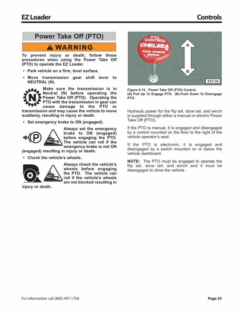
Figure 6-12. Power Take Off (PTO) Control.(A) Pull Up To Engage PTO. (B) Push Down To DisengagePTO.
Hydraulic power for the flip tail, dove tail, and winchis supplied through either a manual or electric PowerTake Off (PTO).
If the PTO is manual, it is engaged and disengagedby a control mounted on the floor to the right of thevehicle operator’s seat.
If the PTO is electronic, it is engaged anddisengaged by a switch mounted on or below thevehicle dashboard.
NOTE: The PTO must be engaged to operate theflip tail, dove tail, and winch and it must bedisengaged to drive the vehicle.
Power Take Off (PTO)
Page 26 Xtreme Manufacturing, LLC
Operation EZ Loader
The winch safety andoperating instructions areprovided to enhance, NOTreplace, the safety andoperating instructions
provided by the winch manufacturer. If you haveany questions about safe winch operatingprocedures, refer to the manufacturer’sinstructions and other applicable industryguidelines and regulations.Failure to follow safe winch operatingprocedures can result in equipment damage,injury, or death to the operator and others.Only allow personnel trained by a qualifiedsupervisor in safe winch operations to operateor maintain the winch.The operator is responsible for exercisingcaution, using common sense, and beingfamiliar with safe rigging techniques. Refer toapplicable industry standards for riggingtechniques, including ASME B30.9 for rigginginformation, American National StandardsInstitute, 1430 Broadway, New York, NY 10018.
Wear proper safety gear such as reflectiveclothing, hardhat, safety shoes, safety glassesand gloves. Always wear gloves when handlingthe wire rope.
DO NOT wear loose fitting clothingthat can become entangled in the wirerope or other moving parts. Keephands, clothing, etc. away frommoving parts.DO NOT place hands in the hook. Usea hook strap to spool and unspool thewire rope to keep hands away frompinch points. DO NOT try to guide thewire rope.
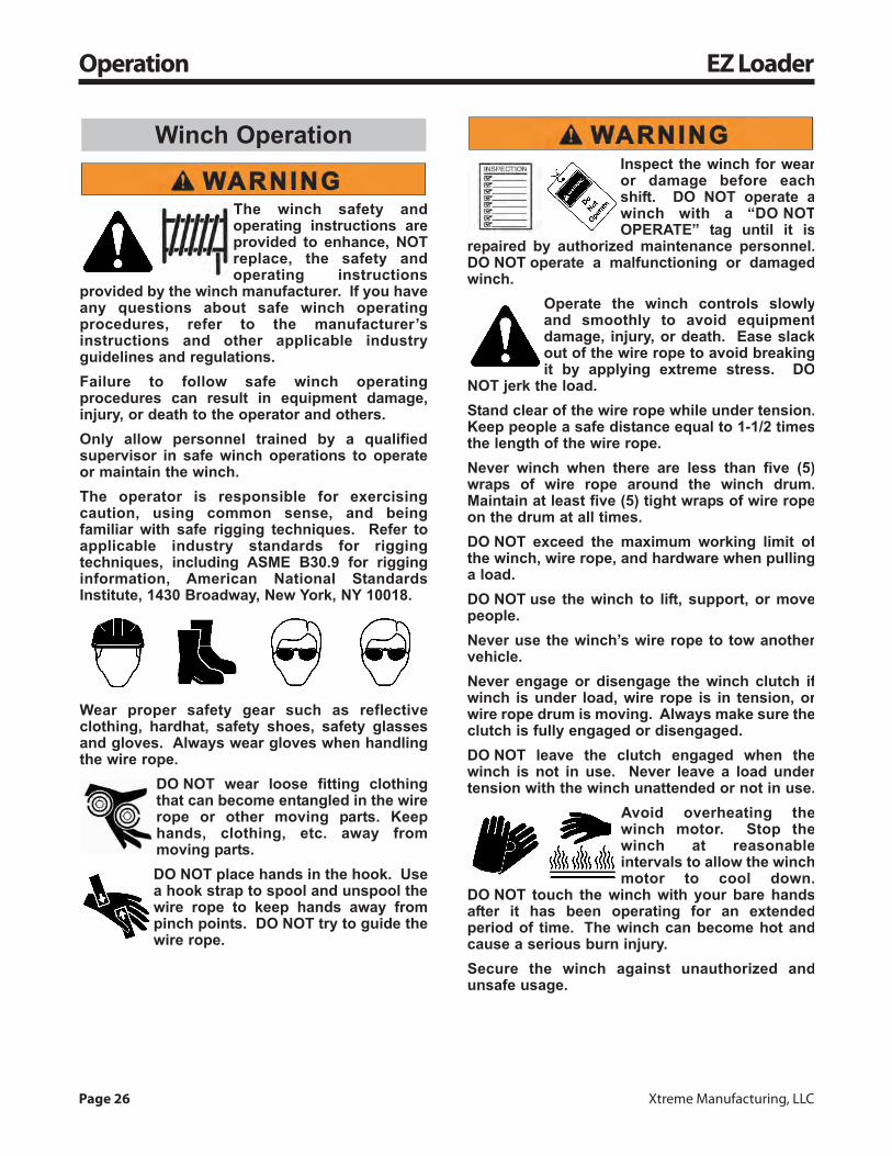
Inspect the winch for wearor damage before eachshift. DO NOT operate awinch with a “DO NOTOPERATE” tag until it is
repaired by authorized maintenance personnel.DO NOT operate a malfunctioning or damagedwinch.
Operate the winch controls slowlyand smoothly to avoid equipmentdamage, injury, or death. Ease slackout of the wire rope to avoid breakingit by applying extreme stress. DO
NOT jerk the load.Stand clear of the wire rope while under tension.Keep people a safe distance equal to 1-1/2 timesthe length of the wire rope.Never winch when there are less than five (5)wraps of wire rope around the winch drum.Maintain at least five (5) tight wraps of wire ropeon the drum at all times.DO NOT exceed the maximum working limit ofthe winch, wire rope, and hardware when pullinga load.DO NOT use the winch to lift, support, or movepeople.Never use the winch’s wire rope to tow anothervehicle.Never engage or disengage the winch clutch ifwinch is under load, wire rope is in tension, orwire rope drum is moving. Always make sure theclutch is fully engaged or disengaged.DO NOT leave the clutch engaged when thewinch is not in use. Never leave a load undertension with the winch unattended or not in use.
Avoid overheating thewinch motor. Stop thewinch at reasonableintervals to allow the winchmotor to cool down.
DO NOT touch the winch with your bare handsafter it has been operating for an extendedperiod of time. The winch can become hot andcause a serious burn injury.Secure the winch against unauthorized andunsafe usage.
Winch Operation
For information call (800) 497-1704 Page 27
EZ Loader Operation
Keep tension on wire rope to avoid slack that canresult in twisting, overwrap, or other damage towire rope.
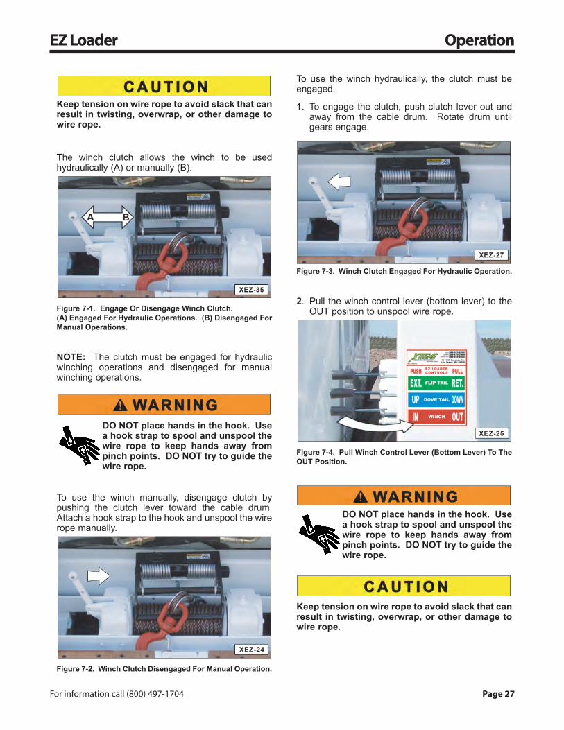
The winch clutch allows the winch to be usedhydraulically (A) or manually (B).
Figure 7-1. Engage Or Disengage Winch Clutch.(A) Engaged For Hydraulic Operations. (B) Disengaged ForManual Operations.
NOTE: The clutch must be engaged for hydraulicwinching operations and disengaged for manualwinching operations.
DO NOT place hands in the hook. Usea hook strap to spool and unspool thewire rope to keep hands away frompinch points. DO NOT try to guide thewire rope.
To use the winch manually, disengage clutch bypushing the clutch lever toward the cable drum.Attach a hook strap to the hook and unspool the wirerope manually.
Figure 7-2. Winch Clutch Disengaged For Manual Operation.
To use the winch hydraulically, the clutch must beengaged.
1. To engage the clutch, push clutch lever out andaway from the cable drum. Rotate drum untilgears engage.
Figure 7-3. Winch Clutch Engaged For Hydraulic Operation.
2. Pull the winch control lever (bottom lever) to theOUT position to unspool wire rope.
Figure 7-4. Pull Winch Control Lever (Bottom Lever) To TheOUT Position.
DO NOT place hands in the hook. Usea hook strap to spool and unspool thewire rope to keep hands away frompinch points. DO NOT try to guide thewire rope.
Keep tension on wire rope to avoid slack that canresult in twisting, overwrap, or other damage towire rope.

Page 28 Xtreme Manufacturing, LLC
Operation EZ Loader
3. Unspool enough wire rope to reach the load andapply safe rigging techniques, according toindustry standards.
Figure 7-5. Unspool Wire Rope.
4. After the load is safely rigged, push the winchcontrol lever (bottom lever) to the IN position tospool wire rope.
Figure 7-6. Push Winch Control Lever (Bottom Lever) ToThe IN Position.
Figure 7-7. Spool (In) Wire Rope.
1. Park EZ Loader on a firm, level surface.
2. Set parking brake.
Chock tires to stop vehiclefrom rolling. Failure tochock tires or improperuse of chocks can causethe vehicle to roll, resulting
in injury or death.
3. Chock wheels.
Figure 7-8. Chock Wheels.
4. Place transmission in neutral.
5. Engage the power take off (PTO).
Figure 7-9. Engage Power Take Off.
NOTE: Always engage the clutch, pull the PTOlever all the way up to engage the PTO, and thenrelease the clutch.
Extend Ramp

For information call (800) 497-1704 Page 29
EZ Loader Operation
6. Extend the ramp.
a. Push the dove tail control lever (middle lever) tothe UP position.
Figure 7-10. Push Dove Tail Control Lever To The UPPosition.
NOTE: This raises the dove tail up and providesclearance to extend the flip tail.
Figure 7-11. Raise Dove Tail Up.
b. Push the flip tail control lever (top lever) to theEXTEND position.
Figure 7-12. Push Flip Tail Control Lever To The EXTENDPosition.
NOTE: This releases the flip tail from the lockingmechanism and extends the flip tail.
Figure 7-13. Make Sure Flip Tail Releases From LockingMechanism.
Figure 7-14. Extend Flip Tail Up.
c. Continue to extend the flip tail until the ramp(dove tail and flip tail) reaches full extension.
Figure 7-15. Make Sure The Ramp (Dove And Flip Tail) IsFully Extended.
Page 30 Xtreme Manufacturing, LLC
Operation EZ Loader
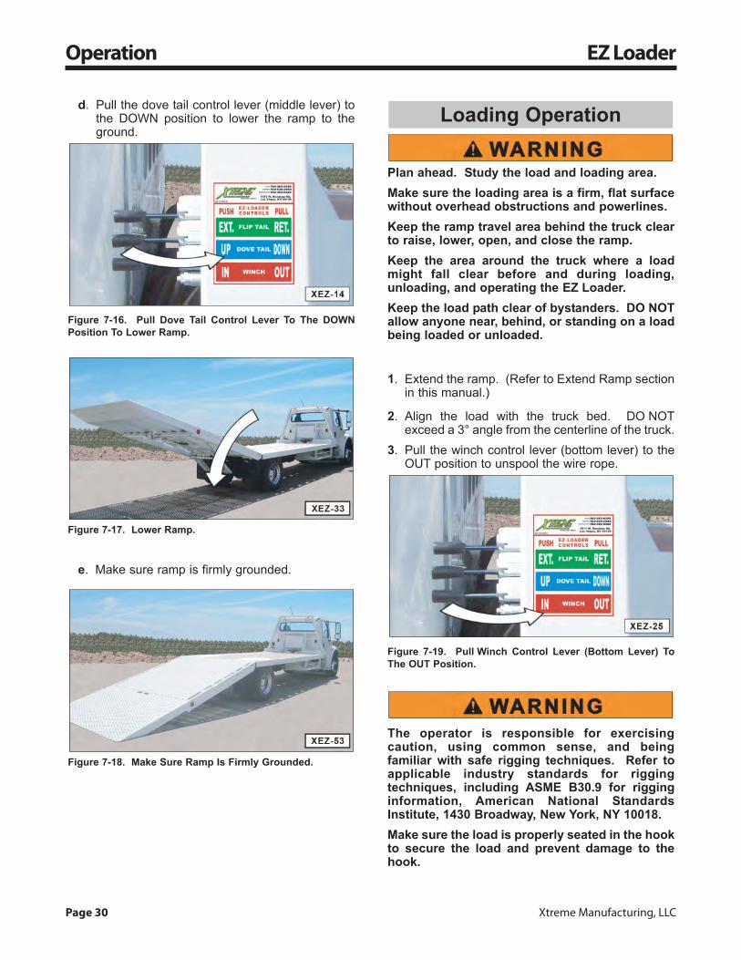
d. Pull the dove tail control lever (middle lever) tothe DOWN position to lower the ramp to theground.
Figure 7-16. Pull Dove Tail Control Lever To The DOWNPosition To Lower Ramp.
Figure 7-17. Lower Ramp.
e. Make sure ramp is firmly grounded.
Figure 7-18. Make Sure Ramp Is Firmly Grounded.
Plan ahead. Study the load and loading area.Make sure the loading area is a firm, flat surfacewithout overhead obstructions and powerlines.Keep the ramp travel area behind the truck clearto raise, lower, open, and close the ramp.Keep the area around the truck where a loadmight fall clear before and during loading,unloading, and operating the EZ Loader.Keep the load path clear of bystanders. DO NOTallow anyone near, behind, or standing on a loadbeing loaded or unloaded.
1. Extend the ramp. (Refer to Extend Ramp sectionin this manual.)
2. Align the load with the truck bed. DO NOTexceed a 3° angle from the centerline of the truck.
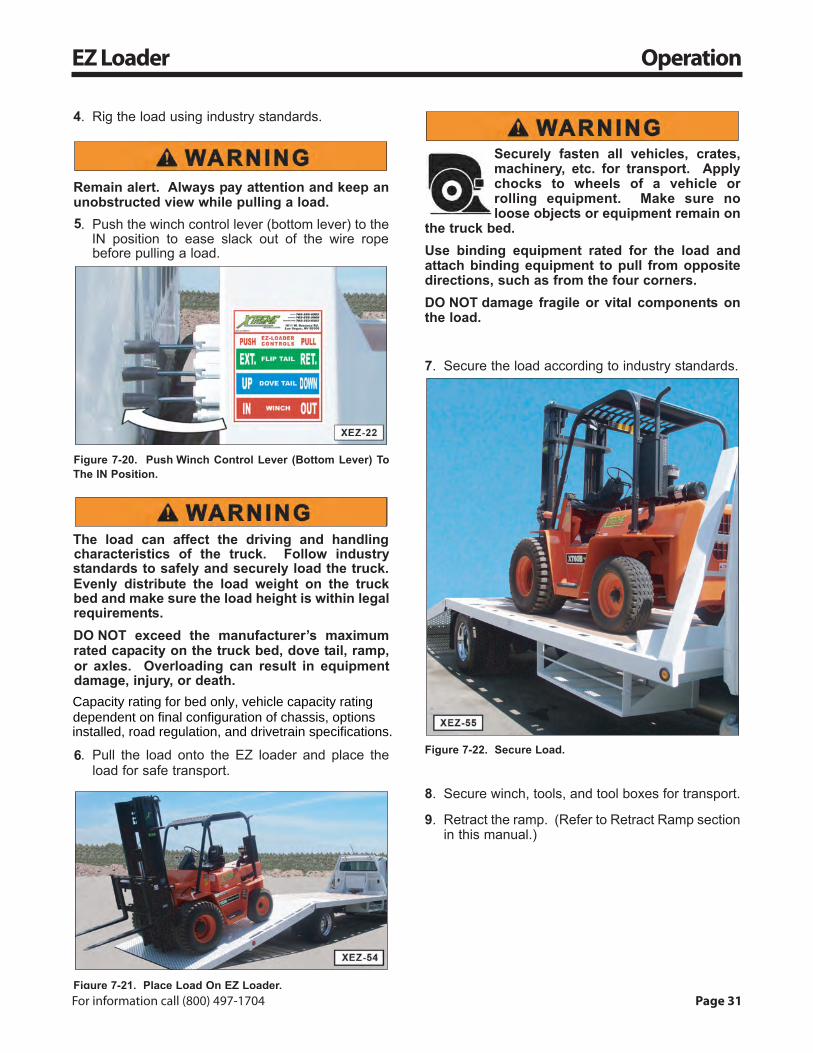
3. Pull the winch control lever (bottom lever) to theOUT position to unspool the wire rope.
Figure 7-19. Pull Winch Control Lever (Bottom Lever) ToThe OUT Position.
The operator is responsible for exercisingcaution, using common sense, and beingfamiliar with safe rigging techniques. Refer toapplicable industry standards for riggingtechniques, including ASME B30.9 for rigginginformation, American National StandardsInstitute, 1430 Broadway, New York, NY 10018.Make sure the load is properly seated in the hookto secure the load and prevent damage to thehook.
Loading Operation
For information call (800) 497-1704 Page 31
EZ Loader Operation
4. Rig the load using industry standards.
Remain alert. Always pay attention and keep anunobstructed view while pulling a load.5. Push the winch control lever (bottom lever) to the
IN position to ease slack out of the wire ropebefore pulling a load.
Figure 7-20. Push Winch Control Lever (Bottom Lever) ToThe IN Position.
The load can affect the driving and handlingcharacteristics of the truck. Follow industrystandards to safely and securely load the truck.Evenly distribute the load weight on the truckbed and make sure the load height is within legalrequirements.DO NOT exceed the manufacturer’s maximumrated capacity on the truck bed, dove tail, ramp,or axles. Overloading can result in equipmentdamage, injury, or death.
6. Pull the load onto the EZ loader and place theload for safe transport.
Figure 7-21. Place Load On EZ Loader.
Securely fasten all vehicles, crates,machinery, etc. for transport. Applychocks to wheels of a vehicle orrolling equipment. Make sure noloose objects or equipment remain on
the truck bed.Use binding equipment rated for the load andattach binding equipment to pull from oppositedirections, such as from the four corners.DO NOT damage fragile or vital components onthe load.
7. Secure the load according to industry standards.
Figure 7-22. Secure Load.
8. Secure winch, tools, and tool boxes for transport.
9. Retract the ramp. (Refer to Retract Ramp sectionin this manual.)
Capacity rating for bed only, vehicle capacity rating dependent on final configuration of chassis, options installed, road regulation, and drivetrain specifications.
Page 32 Xtreme Manufacturing, LLC
Operation EZ Loader
Plan ahead. Study the load and unloading area.Make sure the unloading area is a firm, flatsurface without overhead obstructions andpowerlines.Keep the ramp travel area behind the truck clearto raise, lower, open, and close the ramp.Keep the area around the truck where a loadmight fall clear before and during loading,unloading, and operating the EZ Loader.Keep the load path clear of bystanders. DO NOTallow anyone near, behind, or standing on a loadbeing loaded or unloaded.
1. Extend the ramp. (Refer to Extend Ramp sectionin this manual.)
The operator is responsible for exercisingcaution, using common sense, and beingfamiliar with safe rigging techniques. Refer toapplicable industry standards for riggingtechniques, including ASME B30.9 for rigginginformation, American National StandardsInstitute, 1430 Broadway, New York, NY 10018.Make sure the load is properly seated in the hookto secure the load and prevent damage to thehook.
2. Rig the load using industry standards.
3. Remove load tie-downs and chocks.
4. Pull the winch control lever (bottom lever) to theOUT position to unspool the wire rope and load.
Figure 7-23. Pull Winch Control Lever (Bottom Lever) ToThe OUT Position.
5. Remove load from EZ Loader.
6. Push the winch control lever (bottom lever) to theIN position to spool the wire rope.
Figure 7-24. Push Winch Control Lever (Bottom Lever) ToThe IN Position.
7. Retract the ramp. (Refer to Retract Ramp sectionin this manual.)
Unloading Operation
For information call (800) 497-1704 Page 33
EZ Loader Operation
1. Rectract the ramp.
a. Push the dove tail control lever (middle lever) tothe UP position.
Figure 7-25. Push Dove Tail Control Lever To The UPPosition.
NOTE: This raises the ramp up and providesclearance to retract the flip tail.
Figure 7-26. Raise Ramp Up.
b. Pull the flip tail lever (top Lever) to theRETRACT position.
Figure 7-27. Pull Flip Tail Control Lever To The RETRACTPosition.
NOTE: This retracts the flip tail and engages thelocking mechanism.
Figure 7-28. Retract Flip Tail.
Figure 7-29. Retract Flip Tail.
Figure 7-30. Retract Flip Tail Until It Folds CompletelyUnder The Dove Tail.
Retract Ramp

Page 34 Xtreme Manufacturing, LLC
Operation EZ Loader
Figure 7-31. Make Sure Flip Tail Engages LockingMechanism.
c. Pull dove tail lever (middle lever) to the DOWNposition to lower dove tail.
Figure 7-32. Pull Dove Tail Control Lever To The DOWNPosition.
Figure 7-33. Lower Dove Tail.
2. Remove and secure vehicle wheel chocks.
Figure 7-34. Chock Wheels.
3. Disengage the power take off (PTO).
Figure 7-35. Disengage Power Take Off.
NOTE: Always engage the clutch, push the PTOlever all the way down to disengage the PTO, andthen release the clutch.
4. Release parking brake.
DO NOT drive the EZ Loader unless the flip tail issecured in the stored position by the lockingmechanism. Failure to make sure the flip tail issecured in the storage position can result inequipment damage.

For information call (800) 497-1704 Page 35
EZ Loader Preventive Maintenance
Follow the manufacturer’s instructions forproper maintenance to make sure the vehiclecontinues to meet manufacturer’s specifications.DO NOT operate the vehicle and attachments ifthey require repairs or “Do Not Operate” tagshave been placed on them.Make sure basic maintenance is completed andservice problems are corrected.Injury or death can result from operating avehicle before all repairs have been made and allproper maintenance is completed.
Consult Material SafetyData Sheets (MSDS) forchemical hazards and firstaid instructions. MSDSshould be available from
the manufacturer or supplier of the fluid.
Pressurized water canspray debris, hot fluids, orchemicals on personnel inthe vicinity and can resultin personal injury. Wear
protective clothing, safety shoes, and a faceshield or safety glass when using pressurizedwater for cleaning. DO NOT exceed a maximumof 40 psi (275 kPa) water pressure for cleaningpurposes. Always wear eye protection forcleaning the cooling system.
1. Use a high pressure washer to clean fluids andother debris from the dove tail and flip tail.
2. Check attachment hardware (nuts and bolts) onthe dove tail and flip tail linkage for tightness.Vibration and stress can loosen properly torquedbolts.
3. Make sure all hydraulic fittings are securelyattached.
4. Lubricate all hinges and pivot points withpenetrating oil or spray.
5. Check the hydraulic filter for contamination.When the hydraulic filter gauge is green thisindicates the filter is clean. When the hydraulicfilter gauge is yellow, this indicates the filterneeds to be replaced.
Replace the hydraulic oil filter and oil every six (6)months or sooner if the hydraulic filter indicator isyellow, indicating the filter is dirty.
Check hydraulic oil lines,tubes, and hoses carefully.DO NOT use your barehand to check for leaks.Always use a board or
cardboard when checking for a hydraulic leak.Escaping hydraulic fluid under pressure, even apinhole size leak, can penetrate body tissue,causing injury or death. If hydraulic oil isinjected into your skin, a doctor familiar with thistype of injury must treat it immediately.
Personal injury can resultfrom hydraulic oil pressureor hot oil. DO NOT removea hydraulic tank filler capunless it is cool enough to
touch with bare hands. Remove the hydraulictank filler cap slowly to relieve pressure. Relieveall pressure in a hydraulic system before anycaps, lines, fittings, or related items aredisconnected or removed.
Keep the hydraulic system clean. Service thehydraulic system with extreme care. Failure tochange the hydraulic oil and filter regularly canvoid the warranty of some components. Smallamounts of dirt or foreign material can causeextensive damage to pumps, motors, and valves.DO NOT use brake fluid in the hydraulic system.
1. Before opening hydraulic oil reservoir, wipe awayall dirt, grease, and grime around filter cap. Makesure all containers, funnels, and pouring spouts tobe used are clean.
2. Remove the oil filter. Drain oil into an appropriatecontainer and dispose of properly.
3. Install a 51759 WIX Oil Filter according to filterinstallation instructions.
Replacing Oil and Filter
Semi-Annual Maintenance
Weekly Maintenance

Page 36 Xtreme Manufacturing, LLC
Preventive Maintenance EZ Loader
4. Add up to four (4) quarts of AW46 or AW68CITGO Hydraulic Oil to the hydraulic oil reservoir.Fill the reservoir to the full line on the sight glass.
Figure 8-1. Sight Glass On Hydraulic Oil reservoir.
5. Test all ramp functions.
6. Check for hydraulic leaks.
Figure 8-2. “Do Not Operate” Tags.

For information call (800) 497-1704 Page 37
EZ Loader Preventive Maintenance

1415 W. Bonanza Rd. Las Vegas, NV 89106www.XtremeManufacturing.com
(702) 636-2969(800) 497-1704
24921-000 5/2020