Embed Size (px)
Citation preview

#868-70 • 07 /01P R I N T E D I N U . S . A .
OPERATION and CARE MANUAL
®
COOK/HOLD/SERVE SYSTEMSW 1 6 4 N 9 2 2 1 W a t e r S t r e e t � P . O . B o x 4 5 0 � M e n o m o n e e F a l l s , W i s c o n s i n 5 3 0 5 2 - 0 4 5 0 U . S . A .
PHONE: 262.251.3800 FAX: 262.251.7067 • 800.329.8744 U.S.A. ONLY WEBSITE:800.558.8744 U.S.A./CANADA 262.251.1907 INTERNATIONAL www.alto-shaam.com
Hot Display Case
MODELS: ED-48 EDSYS-48ED-72 EDSYS-72ED-96 EDSYS-96
EDSYS-48

U N PA C K I N G a n d S E T- U P
The Alto-Shaam Display Case has beenthoroughly tested, checked for calibration, andinspected to insure only the highest qualitycabinet is provided. When you receive your cabinet, check for anypossible shipping damage and report it at once to the deliveringcarrier. See Transportation Damage and Claims section located in this manual.
In order to maintain established National Sanitation Foundationstandards, all stationary floor models must be sealed to the floorwith a R.T.V. or silastic meeting N.S.F. requirements or have6"(153mm) unobstructed clearance beneath the unit. Counter andtable units must be mounted on legs of a sufficient 4"(102mm)height to provide minimum unobstructed space beneath the unit.These legs are supplied with the unit. Warranty will become nulland void if these directions are not followed.
Complete and return the warranty card to the factory as soon aspossible to assure prompt service in the event of a warranty partsand labor claim.
NOTE: Any and all claims for warranty must include the full modelnumber and serial number of the cabinet.
E L E C T R I C A L I N S TA L L AT I O N
1. An identification tag is permanently mounted on cabinet.Always position the appliance so the power supply cord iseasily accessible in case of an emergency.
2. Plug the case into a properly grounded receptacle ONLY.Arcing will occur when connecting or disconnecting the displaycase unless all controls are in the OFF position.
H OT
O P E R AT I O N A L P R O C E D U R E S
1. D O N O T A D D W A T E R T O T H E D E L I C A S EHalo Heat display cases maintain a constant but gentletemperature and eliminate much of the moisture loss associatedwith conventional display cases. Because of this gentle heat,it is not necessary to add water to the display case. As a matterof fact, adding water is not recommended since water willaccelerate the deterioration of the product, and may damage the case.
2. P L A C E D I V I D E R S a n d S E R V I N G P A N S I N C A S ERefer to the pan layout diagrams for different types of panaccommodations. A complete pan configuration layout islocated in this manual. It is VERY important to note, no matter
what type of pan configuration you choose, pan separator bars ordivider bars must be used to close all gaps between pans, and allgaps between the pans and the edges of the display case. If these gaps are not closed, the heat will be pulled out of the bottom of the case, into the display area. As aconsequence, heat distribution will be uneven and uniformtemperature will be difficult to hold. If needed, additional pandivider bars are available.
3. TURN DISPLAY LIGHTS “ON” AND SET THETHERMOSTAT(s) AT NUMBER “10” TO PREHEAT.An indicator light will illuminate when the thermostat(s) is (are)turned “ON.” The indicator(s) will remain lit as long as the unitis preheating or calling for heat. The unit should be preheated, atthe number 10 setting, for a minimum of twenty minutes beforeloading the case with food. When preheating iscompleted, or whenever the unit reaches any temperature set bythe operator between 1 and 10, the indicator light(s) willgo “OUT”.
4. L O A D H O T F O O D S I N T O T H E D E L I C A S EBe certain only hot food is transferred into the display case.Before loading food into the case, use a pocket-type meatthermometer to make certain all products have reached aninternal temperature of 140° to 160° F. (60° to 71°C). If any foodproduct is not at proper serving temperature, use a Halo Heatcooking and holding oven, set at 250° to 275°F (121° to 135°C), ora Combitherm oven/steamer, to bring the product within thecorrect temperature range. While in the display case, productsmay be loosely covered with clear plastic wrap. When required,the plastic wrap may remain on the product, in the display case,up until the time it is served.
5. R E S E T T H E R M O S T A T A S N E E D E DAfter all products are loaded into the display case and the doorsare closed, reset the thermostat(s) to the number “8” setting. Thiswill not necessarily be the final setting. Since proper temperaturerange depends on the type of products and the quantities beingheld, it is necessary to periodically use a pocket thermometer tocheck each item to make certain the correct temperatures arebeing maintained. Proper temperature range is between 140°and 160°F (60° and 71°C). Normally, this will require athermostat setting of between number “6” and “8,” although ahigher or lower setting may sometimes be required.
6. S E R V E F R E S H H O T D E L I F O O DKeep hot deli foods looking fresh. Occasionally stir or rotatefoods as needed. Serve products in the proper package orcontainer. Keep deli case doors closed after serving. Wipe spillsimmediately to assure maximum eye appeal.
Operation & Care Manual #868-70 • 1.
THIS UNITS PERFORMANCE HAS BEEN OPTIMIZED USING THEFACTORY PROVIDED LAMPS. THESE LAMPS SHOULD BE
REPLACED WITH AN EXACT REPLACEMENT OR WITH A FACTORYRECOMMENDED REPLACEMENT.
EXAMPLESERIAL NUMBER AND WARRANTY CODE MAXIMUM RATED
WATTAGEIDENTIFICATION MODEL NUMBER
MAXIMUM RATED VOLTAGE MAXIMUM RATED FREQUENCY
MODEL
SERIAL NO. WATTS
1 PHVOLTS
xxx-xx
xxxx-xx xxxx
xx HZxxx AC
ALTO-SHAAM INC. MILW. WI. PAT. NO. 3521030
ENSURE POWER SOURCE
MATCHES VOLTAGE STAMPED
ON NAMEPLATE OF UNIT
DISCONNECT UNIT FROM
POWER SOURCE BEFORE
CLEANING OR SERVICING
HOT DISPLAY CASES®

The cleanliness and appearance of this unit willcontribute considerably to operating efficiency and savory, appetizing food. Good equipment that is kept clean works better and lasts longer.
THOROUGHLY CLEAN THE DISPLAY CASE DAILY
A. Turn lights and adjustable thermostat(s) to the “OFF” position, and disconnect the unit from the power source.
B. Remove, cover or wrap, and store unused products under refrigeration. Let unit cool.
C. Clean the interior metal surfaces of the cabinet witha damp cloth and any good alkaline or alkalinechlorinated based commercial detergent or greasesolvent at the recommended strength. Use a plastic scouring pad or oven cleaner for difficultareas. Avoid the use of abrasive cleaningcompounds, chloride based cleaners, or cleanerscontaining quaternary salts. Rinse well to removeall residue and wipe dry.
NOTE: Never use hydrochloric acid (muriatic acid) on stainless steel.
D. Clean glass with a window cleaner.
E. To help maintain the protective film coating on polishedstainless steel, clean the exterior of the unit with a cleanerrecommended for stainless steel surfaces. Spray thecleaning agent on the cloth and wipe with the grain of thestainless steel.
Always follow appropriate state or local health (hygiene)regulations regarding all applicable cleaning and sanitationrequirements for equipment.
Operation & Care Manual #868-70 • 2.
Hood g lass extended to the fu l l upr ightpos i t ion is s tab i l ized through the use
o f g a s s t r u t s d e s i g n e d fo r t h e f u l ll oad bear ing we igh t . These s t r u tscou ld weaken o r fa i l due t o wea r,
env i ronmenta l condi t ions or ag ing.Operators should be aware of any decrease in effort to liftthe hood and initiate an immediate gas strut safety check.
DO NOT LIFT THE HOOD IN THIS CONDITION.
!C A U T I O N
C A R E a n d C L E A N I N G
Disconnect the unit fromthe power source beforecleaning or servicing.
At no t ime s hou ld th e c a s e b e s t e amc l eaned , f l o oded w i th wa t e r o r
l i qu id s o lu t i on .Do No t Us e Wat e r Je t t o C l ean .
Seve re damage o r e l e c t r i c a l hazard
cou ld re su l t .
SAFETY ALERTThis units performance has been
optimized using the factoryprovided bulbs. These bulbs
should be replaced with anexact replacement or with a
factory recommended replacement. Thesebulbs have been treated to resist breakageand must be replaced with similarlytreated bulbs in order to maintaincompliance with NSF standards.Be careful not to overtightenthe bulbs in their receptacles.

Operation & Care Manual #868-70 • 3.
S A N I TAT I O N G U I D E L I N E SA Food flavor and aroma are usually so closely related that itis difficult, if not impossible, to separate them. There is also animportant, inseparable relationship between cleanliness andfood flavor. Cleanliness, top operating efficiency, andappearance of equipment contribute considerably to savory,appetizing foods. Good equipment that is kept clean, worksbetter and lasts longer.
Most food imparts its own particular aroma and manyfoods also absorb existing odors. Unfortunately, during thisabsorption, there is no distinction between GOOD and BADodors. The majority of objectionable flavors and odorstroubling food service operations are caused by bacteriagrowth. Sourness, rancidity, mustiness, stale or other OFFflavors are usually the result of germ activity.
The easiest way to insure full, natural food flavor isthrough comprehensive cleanliness. This means good controlof both visible soil (dirt) and invisible soil (germs). A thoroughapproach to sanitation will provide essential cleanliness. It willassure an attractive appearance of equipment, along withmaximum efficiency and utility. More importantly, a goodsanitation program provides one of the key elements in theprevention of food-borne illnesses.
A controlled holding environment for prepared foods isjust one of the important factors involved in the prevention offood-borne illnesses. Temperature monitoring and controlduring receiving, storage, preparation, and the service of foodsare of equal importance.
The mostaccuratemethod ofmeasuringsafe temper-atures of bothhot and coldfoods is byinternalproducttemperature. A quality
thermometer is an effective tool for this purpose, and should beroutinely used on all products that require holding at a specifictemperature.
A comprehensive sanitation program should focus on thetraining of staff in basic sanitation procedures. This includespersonal hygiene, proper handling of raw foods, cooking to asafe internal product temperature, and the routine monitoringof internal temperatures from receiving through service.
Most food-borne illnesses can be prevented throughproper temperature control and a comprehensive program ofsanitation. Both these factors are important to build qualityservice as the foundation of customer satisfaction. Safe foodhandling practices to prevent food-borne illness is of criticalimportance to the health and safety of your customers.HACCP, an acronym for Hazard Analysis (at) Critical ControlPoints, is a quality control program of operating procedures toassure food integrity, quality, and safety. Taking stepsnecessary to augment food safety practices are both costeffective and relatively simple. While HACCP guidelines gofar beyond the scope of this manual, additional information isavailable by contacting the USDA/FDA Food-borne IllnessEducation Information Center at (301)504-6803.
G E N E R A L H O L D I N G G U I D E L I N E SChefs, cooks and other specialized food service personnel
employ varied methods of cooking. Proper holdingtemperatures for a specific food product must be based on themoisture content of the product, product density, volume, andproper serving temperatures. Safe holding temperatures mustalso be correlated with palatability in determining the length ofholding time for a specific product.
Halo Heat maintains the maximum amount of productmoisture content without the addition of water, water vapor, orsteam. Maintaining maximum natural product moisturepreserves the natural flavor of the product and provides a moregenuine taste. In addition to product moisture retention, thegentle properties of Halo Heat maintain a consistenttemperature throughout the cabinet without the necessity of aheat distribution fan, thereby preventing further moisture lossdue to evaporation or dehydration.
In an enclosed holding environment, too much moisturecontent is a condition which can be relieved. A productachieving extremely high temperatures in preparation must beallowed to decrease in temperature before being placed in acontrolled holding atmosphere. If the product is not allowed todecrease in temperature, excessive condensation will formincreasing the moisture content on the outside of the product.
Most Halo Heat Holding Equipment is provided with athermostat control between 60° and 200°F (16° to 93°C). If theunit is equipped with vents, close the vents for moist holdingand open the vents for crisp holding.
If the unit is equipped with a thermostat indicating a rangeof between 1 and 10, use a metal-stemmed indicatingthermometer to measure the internal temperature of theproduct(s) being held. Adjust the thermostat setting to achievethe best overall setting based on internal product temperature.
HOLDING TEMPERATURE RANGEMEAT F A H R E N H E I T C E L S I U S
BEEF ROAST — Rare 140°F 60°CBEEF ROAST — Med/Well Done 160°F 71°CBEEF BRISKET 160° — 175°F 71° — 79°CCORN BEEF 160° — 175°F 71° — 79°CPASTRAMI 160° — 175°F 71° — 79°CPRIME RIB — Rare 140°F 60°CSTEAKS — Broiled/Fried 140° — 160°F 60° — 71°CRIBS — Beef or Pork 160°F 71°CVEAL 160° — 175°F 71° — 79°CHAM 160° — 175°F 71° — 79°CPORK 160° — 175°F 71° — 79°CLAMB 160° — 175°F 71° — 79°C
POULTRYCHICKEN — Fried/Baked 160° — 175°F 71° — 79°CDUCK 160° — 175°F 71° — 79°CTURKEY 160° — 175°F 71° — 79°CGENERAL 160° — 175°F 71° — 79°C
FISH/SEAFOODFISH — Baked/Fried 160° — 175°F 71° — 79°CLOBSTER 160° — 175°F 71° — 79°CSHRIMP — Fried 160° — 175°F 71° — 79°C
BAKED GOODSBREADS/ROLLS 120° — 140°F 49° — 60°C
MISCELLANEOUSCASSEROLES 160° — 175°F 71° — 79°CDOUGH — Proofing 80° — 100°F 27° — 38°CEGGS —Fried 150° — 160°F 66° — 71°CFROZEN ENTREES 160° — 175°F 71° — 79°CHORS D'OEUVRES 160° — 180°F 71° — 82°CPASTA 160° — 180°F 71° — 82°CPIZZA 160° — 180°F 71° — 82°CPOTATOES 180°F 82°CPLATED MEALS 180°F 82°CSAUCES 140° — 200°F 60° — 93°CSOUP 140° — 200°F 60° — 93°CVEGETABLES 160° — 175°F 71° — 79°C
THE HOLDING TEMPERATURES LISTED ARE SUGGESTED GUIDELINES ONLY.
I N T E R N A L F O O D P R O D U C T T E M P E R A T U R E S
HOT FOODSDANGER ZONE 40° TO 140°F (4° TO 60°C)
CRITICAL ZONE 70° TO 120°F (21° TO 49°C)SAFE ZONE 140° TO 165°F (60° TO 74°C)
COLD FOODSDANGER ZONE ABOVE 40°F (ABOVE 4°C)
SAFE ZONE 36°F TO 40°F (2°C TO 4°C)
FROZEN FOODSDANGER ZONE ABOVE 32°F (ABOVE 0°C)
CRITICAL ZONE 0° TO 32°F (-18° TO 0°C)SAFE ZONE 0°F OR BELOW (-18°C OR BELOW)

Operation & Care Manual #868-70 • 4.
(35 mm x 706 mm)
(83 mm x 178 mm)
(25 mm x 708 mm)
(25 mm x 324 mm)
(83 mm x 706 mm)
(45 mm x 451 mm)
(150 mm x 706 mm)
(95 mm x 706 mm)
(22 mm x 708 mm)
SHEET PAN DIVIDER BAR
ONE-THIRD SIZE PAN
FULL, HALF AND THIRD SIZE-LONG
FULL, HALF AND THIRD SIZE-SHORT
SHEET PAN DIVIDER BAR
SHEET PAN DIVIDER BAR
SHEET PAN DIVIDER BAR
SHEET PAN FILLER
GASTRONORM DIVIDER (220V)
STANDARD PAN DIVIDER & SEPARATOR BARS
STANDARD PAN SIZES
No de réf.
11046
11047
11317
11318
11319
11320
11357
11732
1865
DIMENSIONSDESCRIPTION 48 72 96
1
1
2
9
1
2
—
—2
—
—
4
15
—
3
2
—
4
—
—
6
21
—
4
3
16
PAN CONFIGURATIONS • HOT DELI DISPLAY CASES
NOTE: ADDITIONAL PAN SEPARATOR BARS MAY BE REQUIRED TO
ACCOMODATE MAXIMUM CAPACITIES.
FULL-SIZE PAN12" x 20" x 2-1/2" (325 mm x 530 mm x 65 mm) GN1/1
ONE-HALF SIZE PAN12" x 10" x 2-1/2" (325 mm x 265 mm x 65 mm) GN1/2
TWO-THIRDS SIZE PAN12' x 14" x 2-1/2" (325 mm x 352 mm x 65 mm) GN 2/3
ONE -THIRD SIZE PAN12" x 6" x 2-1/2" (325 mm x 176 mm x 65 mm) GN1/3
FULL-SIZEPAN
ED-48ED-72
ED-96
3 PAN ZONES 5 PAN ZONES 7 PAN ZONES
— 48 M
OD
ELS
: Up to 12 O
ne-Third S
ize Pans per display case
— 72 M
OD
ELS
: Up to 20 O
ne-Third S
ize Pans per display case
— 96 M
OD
ELS
: Up to 28 O
ne-Third S
ize Pans per display case
MODELS
ONE-HALFSIZE PAN
ONE-HALFSIZE PAN
ONE-THIRDSIZE PAN
TWO-THIRDSSIZE PAN
ONE-THIRDSIZE PAN
ONE-THIRDSIZE PAN
ONE-THIRDSIZE PAN
ONE-THIRDSIZE PAN
ONE-THIRDSIZE PAN
ONE-THIRDSIZE PAN
— 48 M
OD
ELS
: Up to 3 Tw
o Thirds S
ize Pans w
ith 6 One-T
hird Size P
ans per display case—
72 MO
DE
LS: U
p to 5 Two T
hirds Size P
ans with 10 O
ne-Third S
ize Pans per display case
— 96 M
OD
ELS
: Up to 7 Tw
o Thirds S
ize Pans w
ith 14 One-T
hird Size P
ans per display case
— 48 M
OD
ELS
: Up to 6 O
ne -Half S
ize Pans w
ith 3 One-T
hird Size P
ans per display case—
72 MO
DE
LS: U
p to 5 One -H
alf Size P
ans with 5 O
ne-Third S
ize Pans per display case
— 96 M
OD
ELS
: Up to 7 O
ne -Half S
ize Pans w
ith 7 One-T
hird Size P
ans per display case
On
e (1) FU
LL
SIZ
E PA
N an
d o
ne (1) O
NE
- TH
IRD
SIZ
E PA
N p
er pan
zon
e.
— 48 M
OD
ELS
: Up to 3 F
ull Size P
ans with 3 O
ne-Third S
ize Pans per display case
— 72 M
OD
ELS
: Up to 5 F
ull Size P
ans with 5 O
ne-Third S
ize Pans per display case
— 96 M
OD
ELS
: Up to 7 F
ull Size P
ans with 7 O
ne-Third S
ize Pans per display case
On
e (1) FU
LL
SIZ
E PA
N an
d o
ne (1) O
NE
- TH
IRD
SIZ
E PA
N p
er pan
zon
e.
On
e (1) TW
O T
HIR
DS
SIZ
E PA
N an
d tw
o (2) O
NE
- TH
IRD
SIZ
E PA
NS
per p
an zo
ne.
Fo
ur (4) O
NE
- TH
IRD
SIZ
E PA
N p
er pan
zon
e.
ONE-THIRDSIZE PAN
1-3/8"x 27-13/16"
3-1/4" x 7"
1" x 27-7/8"
1" x 12-3/4"
3-1/4" x 27-3/16"
1-3/4" x 17- 3/4"
5-29/32" x 27-13/16"
3-3/4" x 27-13/16"
7/8" x 27-7/8"

Operation & Care Manual #868-70 • 5.
SHEET PAN CONFIGURATIONS • HOT DELI DISPLAY CASES
ED-48
ED-72
ED-96
2 SHEET PAN ZONES3 SHEET PAN
ZONES4 SHEET PAN
ZONES
ONE-THIRDSIZE PAN
ONE-HALFSIZE PAN
72 MODELS3 Full-Size Sheet Pans
per Display Case
48 MODELS2 Full-Size Sheet Pans per Display Case
Or1 Full-Size Sheet Pan2 One-Half Size Pans3 One-Third Size Pans
96 MODELS4 Full-Size Sheet Pans
per Display Case
FULL SIZESHEET PAN
ON
E-T
HIR
DS
IZE
PA
NO
NE
-TH
IRD
SIZ
E P
AN
ONE-HALFSIZE PAN
STANDARD PAN DIVIDER & SEPARATOR BARS
11046
11047
11317
11318
11319
11320
11357
11732
1865
SHEET PAN DIVIDER BAR
ONE-THIRD SIZE PAN
FULL, HALF & THIRD SIZE - LONG
FULL, HALF & THIRD SIZE - SHORT
SHEET PAN DIVIDER BAR
SHEET PAN DIVIDER BAR
SHEET PAN DIVIDER BAR
SHEET PAN FILLER
GASTRONORM DIVIDER (220V)
DIMENSIONS
1-3/8" x 27-13/16"
3-1/4" x 7"
1" x 27-7/8"
1" x 12-3/4"
3-1/4" x 27-3/16"
1-3/4" x 17-3/4"
5-29/32" x 27-13/16"
3-3/4" x 27-13/16"
7/8" x 27-7/8"
DESCRIPTION 48 72 96
1
1
2
9
1
2
—
—
2
—
—
4
15
—
3
2
—
4
—
—
6
21
—
4
3
1
6
(35-mm x 706-mm)
(83-mm x 178-mm)
(25-mm x 708-mm)
(25-mm x 324-mm)
(83-mm x 706-mm)
(45-mm x 451-mm)
(150-mm x 706-mm)
(95-mm x 706-mm)
(22-mm x 708-mm)
MODELS

Operation & Care Manual #868-70 • 6.
Cable Heating Service Kit . . . . . . . . . . . . . . . . . . . . . . . . 4880includes:CB-3045 Cable Heating Element . . . . . . . . . . . . . 134 feetCR-3226 Ring Connector . . . . . . . . . . . . . . . . . . . . . . . . . 4IN-3488 Insulation Corner. . . . . . . . . . . . . . . . . . . . 1 footBU-3105 Shoulder Bushing . . . . . . . . . . . . . . . . . . . . . . . 4BU-3106 Cup Bushing. . . . . . . . . . . . . . . . . . . . . . . . . . . . 4SL-3063 Insulating Sleeve . . . . . . . . . . . . . . . . . . . . . . . . 4TA-3540 High Temperature Tape Roll . . . . . . . . . . 1 rollST-2439 Stud, 10-32. . . . . . . . . . . . . . . . . . . . . . . . . . . . . . 4NU-2215 Hex Nut. . . . . . . . . . . . . . . . . . . . . . . . . . . . . . . . 8
ED-48, EDSYS-48 Cable Kit
Custom Panel Colors . . . . . . . . . . . . . . . . . . . . . . . . . Factory QuoteDual Case— Trim Kit (FOR BU BASE) . . . . . . . . . . . . . . . . . . . . . . . . . . . . . . 4175— Butt Clip (FOR ED BASE) . . . . . . . . . . . . . . . . . . . . . . . . . . . . . 13027— Acrylic Divider . . . . . . . . . . . . . . . . . . . . . . . . . . . . . . . . . GL-2902Interior Ambient Temp. Gauge. . . . . . . . . . . . . . . . . . . . . GU-33384Lamp Bulb, 100W, 130V. . . . . . . . . . . . . . . . . . . . . . . . . . . . LP-33253Menu Board (1) . . . . . . . . . . . . . . . . . . . . . . . . . . . . . . . . . . MB-23093Merchandise Platform . . . . . . . . . . . . . . . . . . . . . . . . . . . . . . . . . 4988Mirropane— Tempered Glass Doors . . . . . . . . . . . . . . . . . . . . . . . . . . . . . . 5980— End Panels. . . . . . . . . . . . . . . . . . . . . . . . . . . . . . . . . . . . . . . . . 4373Outlet without Probe Kit . . . . . . . . . . . . . . . . . . . . . . . . . . . . . . . 5955Outlet with Probe Kit . . . . . . . . . . . . . . . . . . . . . . . . . . . . . . . . . . 5983Pan Separator Bars— Full-size (long) . . . . . . . . . . . . . . . . . . . . . . . . . . . . . . . . . . . . 11317— Half-size/Third-size . . . . . . . . . . . . . . . . . . . . . . . . . . . . . . . 11318— Sheet Pan (short bar) . . . . . . . . . . . . . . . . . . . . . . . . . . . . . . . 11320— Sheet Pan (long bar). . . . . . . . . . . . . . . . . . . . . . . . . . . . . . . . 11357— Gastronorm. . . . . . . . . . . . . . . . . . . . . . . . . . . . . . . . . . . . . . . . 1865— Half-Size Sheet Pan . . . . . . . . . . . . . . . . . . . . . . . . . . . . . . . . . 1805Scale Platform Package— Right-hand . . . . . . . . . . . . . . . . . . . . . . . . . . . . . . . . . . . . . . . 14101— Left-hand. . . . . . . . . . . . . . . . . . . . . . . . . . . . . . . . . . . . . . . . . 14546Shelf Insert (for BU Base). . . . . . . . . . . . . . . . . . . . . . . . . . . . . . . 4062Thermostat Guard Cover. . . . . . . . . . . . . . . . . . . . . . . . . . . . . . . 4571
Custom Panel Colors . . . . . . . . . . . . . . . . . . . . . . . . . Factory QuoteDual Case— Trim Kit (FOR BU BASE) . . . . . . . . . . . . . . . . . . . . . . . . . . . . . . 4175— Butt Clip (FOR ED BASE) . . . . . . . . . . . . . . . . . . . . . . . . . . . . . 13027— Acrylic Divider . . . . . . . . . . . . . . . . . . . . . . . . . . . . . . . . . GL-2902Interior AmbientTemp. Gauge . . . . . . . . . . . . . . . . . . . . . . . . . . . . . . . . . . . GU-33384
Lamp Bulb, 100W, 130V. . . . . . . . . . . . . . . . . . . . . . . . . . . . LP-33253Menu Board System (1) . . . . . . . . . . . . . . . . . . . . . . . . . . . MB-23092Merchandise Platform . . . . . . . . . . . . . . . . . . . . . . . . . . . . . . . . . 4987Mirropane— Tempered Glass Doors . . . . . . . . . . . . . . . . . . . . . . . . . . . . . . 5979— End Panels. . . . . . . . . . . . . . . . . . . . . . . . . . . . . . . . . . . . . . . . . 4373Outlet without Probe Kit . . . . . . . . . . . . . . . . . . . . . . . . . . . . . . . 5940Outlet with Probe Kit . . . . . . . . . . . . . . . . . . . . . . . . . . . . . . . . . . 5967Pan Separator Bars— Sheet Pan (long bar). . . . . . . . . . . . . . . . . . . . . . . . . . . . . . . . 11046— One-Third Size Pan . . . . . . . . . . . . . . . . . . . . . . . . . . . . . . . . 11047— Full-size (long) . . . . . . . . . . . . . . . . . . . . . . . . . . . . . . . . . . . . 11317— Half-size/Third-size . . . . . . . . . . . . . . . . . . . . . . . . . . . . . . . 11318— Sheet Pan . . . . . . . . . . . . . . . . . . . . . . . . . . . . . . . . . . . . . . . . 11319— Sheet Pan (short bar) . . . . . . . . . . . . . . . . . . . . . . . . . . . . . . . 11320— Gastronorm. . . . . . . . . . . . . . . . . . . . . . . . . . . . . . . . . . . . . . . . 1865— Half-Size Sheet Pan . . . . . . . . . . . . . . . . . . . . . . . . . . . . . . . . 11805Scale Platform Package— Right-hand . . . . . . . . . . . . . . . . . . . . . . . . . . . . . . . . . . . . . . . 14101— Left-hand. . . . . . . . . . . . . . . . . . . . . . . . . . . . . . . . . . . . . . . . . 14546Shelf Insert (for BU Base). . . . . . . . . . . . . . . . . . . . . . . . . . . . . . . 4062Thermostat Guard Cover. . . . . . . . . . . . . . . . . . . . . . . . . . . . . . . 4571
Custom Panel Colors . . . . . . . . . . . . . . . Factory QuoteDual Case Trim Kit (FOR BU BASE) . . . . . . . . . . . . . 4175Dual Case Butt Clip (FOR ED BASE) . . . . . . . . . . . . . 13027Acrylic Divider . . . . . . . . . . . . . . . . . . . . . . . . . . . . . . . . . . . . GL-2902Interior Ambient Temp. Gauge . . . . . . . . . . . . GU-33384Lamp Bulb, 100W, 130V . . . . . . . . . . . . . . . . LP-33253Menu Board System (2) . . . . . . . . . . . . . . . . MB-23092Merchandise Platform . . . . . . . . . . . . . . . . . . . 4989Mirropane Glass Doors . . . . . . . . . . . . . . . . . . . 5981Mirropane End Panels . . . . . . . . . . . . . . . . . . . 4373Outlet with Probe Kit . . . . . . . . . . . . . . . . . . . 5984Outlet without Probe Kit . . . . . . . . . . . . . . . . . . 5957Pocket Thermometer °F . . . . . . . . . . . . . . . . TH-3300Pocket Thermometer °C . . . . . . . . . . . . . . . . TH-3412Pan Separator Bars—Full-size (long) . . . . . . . . . . . . . . . . . . . . . 11317—Half-size/Third-size . . . . . . . . . . . . . . . . . . 11318—Sheet Pan (short bar) . . . . . . . . . . . . . . . . . . 11320—Sheet Pan (long bar) . . . . . . . . . . . . . . . . . . 11357—Sheet Pan Filler Bar . . . . . . . . . . . . . . . . . . . 11732—Gastronorm Divider . . . . . . . . . . . . . . . . . . . 1865—Third-size (short) . . . . . . . . . . . . . . . . . . . . 11915—Third-size (long) . . . . . . . . . . . . . . . . . . . . 11916Scale Platform Package— Right-hand . . . . . . . . . . . . . . . . . . . . . . . 14101— Left-hand . . . . . . . . . . . . . . . . . . . . . . . 14546Shelf Insert (FOR BU BASE) . . . . . . . . . . . . . . . . . 4294Thermostat Guard Cover . . . . . . . . . . . . . . . . . . 4571
Cable Heating Service Kit . . . . . . . . . . . . . . . . . . . . . . . . 4881includes:CB-3045 Cable Heating Element . . . . . . . . . . . . . 210 feetCR-3226 Ring Connector . . . . . . . . . . . . . . . . . . . . . . . . 12IN-3488 Insulation Corner. . . . . . . . . . . . . . . . . . . . 1 footBU-3105 Shoulder Bushing . . . . . . . . . . . . . . . . . . . . . . 12BU-3106 Cup Bushing. . . . . . . . . . . . . . . . . . . . . . . . . . . 12SL-3063 Insulating Sleeve . . . . . . . . . . . . . . . . . . . . . . . 12TA-3540 High Temperature Tape Roll . . . . . . . . . . 1 rollST-2439 Stud, 10-32. . . . . . . . . . . . . . . . . . . . . . . . . . . . . 12NU-2215 Hex Nut. . . . . . . . . . . . . . . . . . . . . . . . . . . . . . . 24
ED-72, EDSYS-72 / ED-96, EDSYS-96 Cable KitKit
ED-48, EDSYS-48 Options & Accessories
ED-72, EDSYS-72 Options & Accessories
ED-96, EDSYS-96 Options & Accessories
SAFETY ALERTThis units performance has been
optimized using the factoryprovided bulbs. These bulbs
should be replaced with anexact replacement or with a
factory recommended replacement. Thesebulbs have been treated to resist breakageand must be replaced with similarlytreated bulbs in order to maintaincompliance with NSF standards.Be careful not to overtightenthe bulbs in their receptacles.
D i s c o n n e c t U n i t f r o m P o w e r S o u r c e B e f o r e
C l e a n i n g o r S e r v i c i n g .

INSTALLATION INSTRUCTIONS — CUSTOMER HEAT GUARD
1. Lift hood glass up. Remove the 6-32 x 1" screws fordraft strip located on the lower front of the case.2. Align the holes in the plexiglas heat guardwiththe holes of the draft strip. Secure in place with 6-32 x 1" screws provided. Tighten securely.
INSTALLATION INSTRUCTIONS — OPTIONAL SCALE PLATFORM1. Disconnect the unit from the power source.2. Lift hood glass up to access the outer top.3. Position the platform mounting bracket in the desired
location along the upper rear edge on the outer top, making sure that the bracket is tight against the bend in the top. Using the bracket as a template, mark and punch six mounting holes in the outer top. Drill these six holes with a No. 21 drill, and tap with a 10-32 UNF thread.
4. Attach the scale shelf assembly to the outer top using thesix 10-32x1/2" slotted truss-head screws provided (Alto-Shaam part number SC-2661).
5. Remove the four nuts from the bottom of the platform. Mount support (bracket provided) to platform using screws as a guide. While pushing up on support, mark two mounting holes on the support.
6. Remove the support. Drill these mounting holes with a No. 21 drill and tap with a 10-32" UNF thread. Replace support and mount to unit with the two 10-32x1/2" screwsprovided (Alto-Shaam part number SC-2661). Replace nuts on platform bottom and tighten support to platform.
7. Apply a silicone bead to all perimeter meeting surfaces between the mounting bracket and the outer top.
NOTE: These platforms are intended for use in the CLOSED position ONLY. They slide away from the unit for cleaning. Using scales with platforms in the OUT position may result in incorrect data on scales.
The scale shelf platform can be removed from the mounting bracket assembly by removing the 10-32 screw/stoplocated on the bottom of the scale shelf. Removing the screw allows the shelf to be slid past, and lifted off the shelf
guide pins. Failure to replace this screw prior to use could result in serious bodily injury, and/or damage toequipment.
D O N OT OV E R T I G H T E N ! D O N OT U S E T H R E A D T I G H T E N I N G
C O M P O U N D S S U C H A S " LO C K T I T E " .
Operation & Care Manual #868-70 • 7.

Operation & Care Manual #868-70 • 8.
E D - 4 8 D I S P L AY C A S E12/22/00
PART DESCRIPTION QTY A/S PT NO.
1. CORD, (120/240V), 7’ (2134mm) 1 CD-3291CORD, (220V), 7’ (2134mm) 1 CD-3545CONNECTOR, 1/2" (13mm) CABLE 1 CR-33542PLUG (120V only) 1 PG-3267
2. BOTTOM 1 11053
3. BOTTOM MOUNTING SCREWS 12 SC-2425
4. INSULATION:SIZE: 15” x 40” (381mm x 1016mm) 2 IN-22364
5. CABLE CONNECTION HARDWARE
6. HEATING CABLE (length): 132’ (40234mm) 1 CB-3045
7. CONTROL PLATE 2 11167CONTROL PLATE MOUNTING SCREWS 8 SC-2459
8. THERMOSTAT 2 TT-3498THERMOSTAT KNOB 2 KN-3473
9. HEAT INDICATOR LIGHT 2 LI-3025
10. LAMP SWITCH 2 SW-3616DIODE ASSEMBLY [120V only] 2 4775
11. TOP 1 1437
12. TOP MOUNTING SCREWS 8 SC-2425
13. LAMP BULB (130V) 6 LP-33592LAMP BULB (220V) 6 LP-3384
14. LAMP SOCKET (120V) 6 RP-3952LAMP SOCKET (220V) 6 RP-3955
15. GLASS DOOR ASSEMBLY, INCLUDES 1 DR-25022-LEFT HAND OUTER DOOR 1 DR-25023-RIGHT HAND INNER DOOR 1 DR-25024-OPTIONAL GLSSS DOOR ASS'Y 1 DR-25025-OPTONAL MIRRORED LEFT HAND OUTER DOOR 1 DR-25026-OPTIONAL MIRRORED RIGHT HAND INNER DOOR 1 DR-25027-TOP TRACK 1 13008-GUIDES #44049 4 DR-22480FDOOR BUMPER ASS'Y 1 DR-22480GGUIDES 4 GI-2367
16. DOOR RETAINERS 2 11279DOOR RETAINER MOUNTING SCREWS 4 SC-2459
17. GLASS, END 2 GL-2901
18. GLASS, FRONT 1 GL-2798
19. LIGHT GUARD 1 4869
20. CAPILLARY COVER PLATE 2 11160CAPILLARY COVER PLATE MTG. SCREWS 16 SC-2459
21. CUTTING BOARD ASSEMBLY 1 4016
22. CUTTING BOARD BRACKET BASE 2 11283
23. CUTTING BOARD BRACKET 2 BT-2342
24. BRACKET TO BRACKET MTG. SCREWS 6 SC-2070
25. GAS STRUT 1 SU-2870
PART DESCRIPTION QTY A/S PT NO.
26. PAN DIVIDER BARS [NOT SHOWN]—SHEET PAN, 1-3/8” x 27-13/16” (35mm x 706mm) 1 11046—THIRD SIZE PAN 3-1/4” x 7” (83mm x 178mm) 1 11047— FULL, HALF & THIRD SIZE (LONG BAR)
1” x 27-7/8” (25.4mm x 708mm) 2 11317— FULL, HALF & THIRD SIZE (SHORT BAR)
1” x 12-3/4” (25.4mm x 324mm) 9 11318—SHEET PAN, 3-1/4” x 27-13/16” (83mm x 706mm) 1 11319—SHEET PAN, 1-3/4” x 17-3/4” (45mm x 451mm) 2 11320—GASTRONORM DIVIDER (220V only) 2 1865
27. CUSTOMER HEAT GUARD 1 GD-2966DRAFT STRIP 1 1246DRAFT STRIP GASKET: 3.5' (1067mm) 1 GS-22441
28. OUTLET W/O PROBE RETROFIT KIT (NOT SHOWN) 1 5940OUTLET W/PROBE RETROFIT KIT (NOT SHOWN) 1 5967DECOR CUSTOMER PANEL (SPECIFY COLOR) 1 11480DECOR END PANEL (SPECIFY COLOR) 2 11483DECOR CUSTOMER PANEL (STAINLESS STEEL) 1 11479DECOR END PANEL (STAINLESS STEEL) 2 11482DECOR CUSTOMER PANEL (WHITE VINYL) 1 12711DECOR END PANEL (WHITE VINYL) 2 12713DECOR CUSTOMER PANEL (RED VINYL) 1 12712DECOR END PANEL (RED VINYL) 2 12714
29. 4” LEGS 4 LG-2044
SERVICE VIEW • ED-48 — PAGE 9
E D S Y S - 4 8 S Y S T E M
PART DESCRIPTION QTY A/S PT NO.
1. ED-48 HOT DELI DISPLAY CASE 1 ______
2. END TRIM CAP (left-hand) 1 1154END TRIM CAP (left-hand) MOUNTING SCREWS 3 SC-2425
3. END TRIM CAP (right-hand) 1 1562END TRIM CAP (right-hand) MOUNTING SCREWS 3 SC-2425
4. TRIM LOCK CHANNEL 1 1701
5. MULLION COVER 1 4865MULLION COVER MOUNTING SCREWS 1 SC-2459
6. LEVELING BOLT 4 SC-2242
7. OUTLET W/O PROBE RETROFIT KIT (NOT SHOWN) 1 5940OUTLET W/PROBE RETROFIT KIT 1 5967
DECOR PANELS:CUSTOMER PANEL — STAINLESS STEEL 1 11604END PANEL — S/S (right-hand) 1 11607END PANEL — S/S (left-hand) 1 11610CUSTOMER PANEL — PAINTED (SPECIFY COLOR) 1 11069END PANEL — PAINTED (right-hand) (SPECIFY COLOR) 1 1340END PANEL — PAINTED (left-hand) (SPECIFY COLOR) 1 1442CUSTOMER PANEL — WHITE VINYL 1 12719END PANEL — WHITE VINYL (right-hand) 1 12721END PANEL — WHITE VINYL (left-hand) 1 12723CUSTOMER PANEL — RED VINYL 1 12720END PANEL — RED VINYL (right-hand) 1 12722END PANEL — RED VINYL (left-hand) 1 12724DECOR PANELS — 51" HIGH SYSTEM:CUSTOMER PANEL PAINTED 1 12137END PANEL — PAINTED (RH) 1 12135END PANEL — PAINTED (LH) 1 12136
SERVICE VIEW • EDSYS-48 SYSTEM— PAGE 10
SERVICE VIEW PARTS LISTS
Operation & Care Manual #868-70 • 9.

Operation & Care Manual #868-70 • 10.

Operation & Care Manual #868-70 • 11.
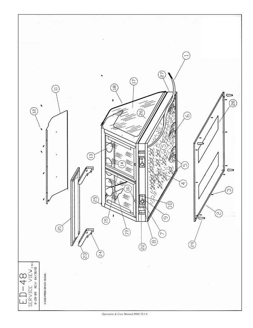
E D - 7 2 D I S P L AY C A S E
12/20/00PART DESCRIPTION QTY A/S PT NO.
1. CORD, (120/240V), 7' (2134mm) 1 CD-3557CORD, (220V), 7’ (2134mm) 1 CD-3607CONNECTOR, 1/2" (13mm) CABLE 1 CR-33542PLUG (120/240 V only) 1 PG-3267
2. BOTTOM 1 1898
3. BOTTOM MOUNTING SCREWS 16 SC-2425
4. INSULATION: 15” x 65” (381mm x 1651mm) PIECE 2 IN-22364
5. CABLE CONNECTION HARDWARE
6. HEATING CABLE (length): 199’ (60655mm) 1 CB-3045
7. CONTROL PLATE 2 11167CENTER CONTROL PLATE 1 11770CONTROL PLATE MOUNTING SCREWS 12 SC-2459
8. THERMOSTAT 2 TT-3498THERMOSTAT KNOB 2 KN-3473
9. HEAT INDICATOR LIGHT (120V) 2 LI-3027HEAT INDICATOR LIGHT (220V) 2 LI-3025
10. LAMP SWITCH 3 SW-3616DIODE ASSEMBLY (120V only) 3 4775
11. FUSEHOLDER (120V UNITS) 2 FU-33041FUSEHOLDER MOUNTING SCREWS 4 SC-2425FUSEHOLDER MOUNTING BRACKET 2 12251FUSEHOLDER BRACKET MOUNTING SCREWS 4 SC-2459FUSE, 15 AMP 2 FU-3775
12. TOP 1 1433
13. TOP MOUNTING SCREWS 13 SC-2425
14. LAMPS BULBS (130V) 10 LP-33592LAMP BULBS (220V) 10 LP-3384
15. LAMP SOCKET (120V) 10 RP-3952LAMP SOCKET (220V) 10 RP-3955
16. GLASS DOOR ASSEMBLY, INCLUDES 1 DR-25028— LEFT HAND INNER DOOR 1 DR-25031— LEFT HAND OUTER DOOR 1 DR-25029— RIGHT HAND OUTER DOOR 1 DR-25030— RIGHT HAND INNER DOOR 1 DR-25032— OPTIONAL MIRRORED GLASS DOOR ASB 1 DR-25033— LEFT HAND INNER MIRRORED DOOR 1 DR-25036— LEFT HAND OUTER MIRRORED DOOR 1 DR-25034— RIGHT HAND OUTER MIRRORED DOOR 1 DR-25035— RIGHT HAND INNER MIRRORED DOOR 1 DR-25037— TOP TRACK 1 13009— GUIDES #44049 8 DR-22480F— POOR BUMPER ASS'Y 2 DR-22480G— GUIDES 8 GI-2367
17. DOOR RETAINER 4 11279DOOR RETAINER MOUNTING SCREWS 8 SC-2459
18. GLASS END 2 GL-2901
19. GLASS, FRONT 1 GL-2799
20. LIGHT GUARD 1 4832
21. CAPILLARY COVER PLATE 2 11160CAPILLARY COVER PLATE MOUNTING SCREWS 16 SC-2459
22. CUTTING BOARD ASSEMBLY 1 4017
23. CUTTING BOARD BRACKET BASE 2 11283
24. CUTTING BOARD BRACKET 2 BT-2342
25. BRACKET TO BRACKET MOUNTING SCREWS 6 SC-2070
26. GAS STRUT 2 SU-2870
PART DESCRIPTION QTY A/S PT NO.
27. PAN DIVIDER BARS [not shown]— FULL, HALF & THIRD SIZE (LONG BAR)
1” x 27-7/8” (25.4mm x 708mm) 4 11317— FULL, HALF & THIRD SIZE (SHORT BAR)
1” x 12-3/4” (25.4mm x 324mm) 15 11318—SHEET PAN, 1-3/4” x 17-3/4” (45mm x 451mm) 3 11320—SHEET PAN,
5-29/32” x 27-13/16” (150mm x 706mm) 2 11357—GASTRONORM DIVIDER (220V only) 4 1865
28. CUSTOMER HEAT GUARD 1 GD-2967DRAFT STRIP 1 1247DRAFT STRIP GASKET: 5.6’ (1077mm) 1 GS-22441
29. OUTLET W/O PROBE RETROFIT KIT (NOT SHOWN) 1 5955OUTLET W/PROBE RETROFIT KIT (NOT SHOWN) 1 5983DECOR CUSTOMER PANEL (SPECIFY COLOR) 1 11508DECOR END PANEL (SPECIFY COLOR) 2 11483DECOR CUSTOMER PANEL (STAINLESS STEEL) 1 11485DECOR END PANEL (STAINLESS STEEL) 2 11482DECOR CUSTOMER PANEL (WHITE VINYL) 1 12715DECOR END PANEL (WHITE VINYL) 2 12713DECOR CUSTOMER PANEL (RED VINYL) 1 12716DECOR END PANEL (RED VINYL) 2 12714
30. 4” LEGS 6 LG-2044
SERVICE VIEW • ED-72 — PAGE 12
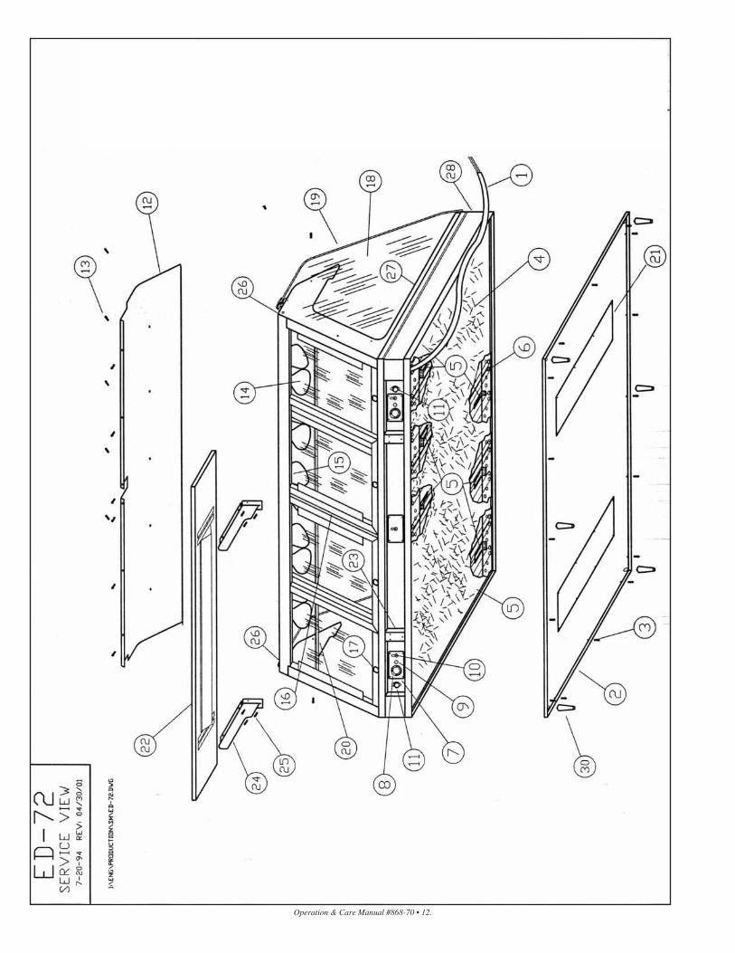
E D S Y S - 7 2 S Y S T E M
1. ED-72 HOT DELI DISPLAY CASE 1 ______
2. END TRIM CAP (left-hand) 1 1154END TRIM CAP (left-hand) MOUNTING SCREWS 3 SC-2425
3. END TRIM CAP (right-hand) 1 1562END TRIM CAP (right-hand) MOUNTING SCREWS 3 SC-2425
4. TRIM LOCK CHANNEL 1 1557
5. MULLION COVER 1 4865MULLION COVER MOUNTING SCREWS 1 SC-2459
6. LEVELING BOLT 4 SC-2242
7. OUTLET W/O PROBE RETROFIT KIT (NOT SHOWN) 1 5955OUTLET W/PROBE RETROFIT KIT 1 5983
DECOR PANELS:CUSTOMER PANEL — STAINLESS STEEL 1 11613END PANEL — S/S (right-hand) 1 11607END PANEL — S/S (left-hand) 1 11610CUSTOMER PANEL — PAINTED (SPECIFY COLOR) 1 11072END PANEL — PAINTED (right-hand) (SPECIFY COLOR) 1 1340END PANEL — PAINTED (left-hand) (SPECIFY COLOR) 1 1442CUSTOMER PANEL — WHITE VINYL 1 12725END PANEL — WHITE VINYL (right-hand) 1 12721END PANEL — WHITE VINYL (left-hand) 1 12723CUSTOMER PANEL — RED VINYL 1 12726END PANEL — RED VINYL (right-hand) 1 12722END PANEL — RED VINYL (left-hand) 1 12724DECOR PANELS — 51” HIGH SYSTEM:CUSTOMER PANEL — PAINTED 1 12141END PANEL — PAINTED (RH) 1 12135END PANEL — PAINTED (LH) 1 12136
SERVICE VIEW • EDSYS-72 — PAGE 13
Operation & Care Manual #868-70 • 12.
Operation & Care Manual #868-70 • 13.

Operation & Care Manual #868-70 • 14.
E D - 9 6 D I S P L AY C A S E
12/22/00PART DESCRIPTION QTY A/S PT NO.
1. CORD, (120/240V), 7’ (2134mm) 1 CD-3557CORD, (220V), 7’ (2134mm) 1 CD-3304CONNECTOR, 1/2" (13mm) CABLE 1 CR-33542PLUG (120/240V only) 1 PG-3267
2. BOTTOM 1 11249
3. BOTTOM MOUNTING SCREWS 18 SC-2425
4. INSULATION: 15” x 96” (381mm x 2438mm) piece 2 IN-22364
5. CABLE CONNECTION HARDWARE
6. HEATING CABLE (length): 183’ (55778mm) 1 CB-3045
7. CONTROL PLATE 3 11167
8. CONTROL PLATE MOUNTING SCREWS 12 SC-2459
9. THERMOSTAT 3 TT-3498THERMOSTAT KNOB 3 KN-3473
10. HEAT INDICATOR LIGHT (120V) 3 LI-3025
11. LAMP SWITCH 3 SW-3616DIODE ASSEMBLY [120V only] 3 4775
12. FUSEHOLDER (120V UNITS) 1 FU-33041FUSEHOLDER MOUNTING SCREWS 2 SC-2425FUSEHOLDER MOUNTING BRACKET 1 12251FUSEHOLDER BRACKET MOUNTING SCREWS 2 SC-2459FUSE, 20 AMP 1 FU-33042
13. TOP 1 11166
14. TOP MOUNTING SCREWS 17 SC-2425
15. LAMPS BULBS (120V) 14 LP-3333LAMP BULBS (220V) 14 LP-3384
16. LAMP SOCKET (120V) 14 RP-3952LAMP SOCKET (220V) 14 RP-3955
17. GLASS DOOR ASSEMBLY, INCLUDES 1 DR-25038-LEFT HAND INNER DOOR 1 DR-25041-LEFT HAND OUTER DOOR 1 DR-25039-RIGHT HAND OUTER DOOR 1 DR-25040-RIGHT HAND INNER DOOR 1 DR-25042-OPTIONAL MIRRORED GLASS DOOR ASS'Y 1 DR-25043-LEFT HAND INNER MIRRORED DOOR 1 DR-25046-LEFT HAND OUTER MIRRORED DOOR 1 DR-25044-RIGHT HAND OUTER MIRRORED DOOR 1 DR-25045-RIGHT HAND INNER MIRRORED DOOR 1 DR-25047-TOP TRACK 1 13010-GUIDES #44049 8 DR-22480F-DOOR BUMPER ASS'Y 2 DR-22480G-GUIDES 8 GI-2367
18. DOOR RETAINERS 4 11279DOOR RETAINER MOUNTING SCREWS 8 SC-2459
19. GLASS, END 2 GL-2901
20. GLASS, FRONT 2 GL-2800
21. LIGHT GUARD 2 4885
22. CAPILLARY COVER PLATE 3 11160CAPILLARY PLATE MOUNTING SCREWS 24 SC-2459
23. CUTTING BOARD ASSEMBLY 2 4016
24. CUTTING BOARD BRACKET BASE 4 11283
25. CUTTING BOARD BRACKET 4 BT-2342
26. BRACKET TO BRACKET MTG. SCREWS 12 SC-2070
27. GAS STRUT 1 SU-2870
PART DESCRIPTION QTY A/S PT NO.
28. PAN DIVIDER BARS [not shown]— FULL, HALF & THIRD SIZE (LONG BAR)
1” x 27-7/8” (25.4mm x 708mm) 6 11317— FULL, HALF & THIRD SIZE (SHORT BAR)
1” x 12-3/4” (25.4mm x 324mm) 21 11318—SHEET PAN, 1-3/4” x 17-3/4” (45mm x 451mm) 4 11320—SHEET PAN,
5-29/32” x 27-13/16” (150mm x 706mm) 3 113573-3/4” X 27-13/16” (95mm x 706mm) 1 11732
—GASTRONORM DIVIDER (220V only) 6 1865
29. CUSTOMER HEAT GUARD 1 GD-2968DRAFT STRIP 1 1258DRAFT STRIP GASKET: 7.8’ (2377mm) 1 GS-22441
30. OUTLET W/O PROBE RETROFIT KIT (NOT SHOWN) 1 5957OUTLET W/PROBE RETROFIT KIT (NOT SHOWN) 1 5984DECOR CUSTOMER PANEL (SPECIFY COLOR) 1 11601DECOR END PANEL (SPECIFY COLOR) 2 11483DECOR CUSTOMER PANEL (STAINLESS STEEL) 2 11600DECOR END PANEL (STAINLESS STEEL) 2 11482DECOR CUSTOMER PANEL (WHITE VINYL) 2 12717DECOR END PANEL (WHITE VINYL) 2 12713DECOR CUSTOMER PANEL (RED VINYL) 2 12718DECOR END PANEL (RED VINYL) 2 12714
31. 4” LEGS 6 LG-2044
SERVICE VIEW • ED-96 — PAGE 15
E D S Y S - 9 6 S Y S T E M
1. ED-96 HOT DELI DISPLAY CASE 1 ______
2. END TRIM CAP (left-hand) 1 1154END TRIM CAP (left-hand) MOUNTING SCREWS 3 SC-2425
3. END TRIM CAP (right-hand) 1 1562END TRIM CAP (right-hand) MOUNTING SCREWS 3 SC-2425
4. TRIM LOCK CHANNEL 1 1683
5. MULLION COVER 1 4865MULLION COVER MOUNTING SCREWS 1 SC-2459
6. LEVELING BOLT 4 SC-2242
7. OUTLET W/O PROBE RETROFIT KIT (NOT SHOWN) 1 5957OUTLET W/PROBE RETROFIT KIT 1 5984
DECOR PANELS:CUSTOMER PANEL — STAINLESS STEEL 1 11616END PANEL — S/S (right-hand) 1 11607END PANEL — S/S (left-hand) 1 11610CUSTOMER PANEL — PAINTED (SPECIFY COLOR) 1 1542END PANEL — PAINTED (right-hand) (SPECIFY COLOR) 1 1340END PANEL — PAINTED (left-hand) (SPECIFY COLOR) 1 1442CUSTOMER PANEL — WHITE VINYL 1 12727END PANEL — WHITE VINYL (right-hand) 1 12721END PANEL — WHITE VINYL (left-hand) 1 12723CUSTOMER PANEL — RED VINYL 1 12728END PANEL — RED VINYL (right-hand) 1 12722END PANEL — RED VINYL (left-hand) 1 12724DECOR PANELS — 51” HIGH SYSTEM:CUSTOMER PANEL — PAINTED 1 12144END PANEL — PAINTED (RH) 1 12135END PANEL — PAINTED (LH) 1 12136
SERVICE VIEW • EDSYS-96 SYSTEM— PAGE 16

Operation & Care Manual #868-70 • 15.

Operation & Care Manual #868-70 • 16.

Operation & Care Manual #868-70 • 17.

Operation & Care Manual #868-70 • 18.

Operation & Care Manual #868-70 • 19.

Operation & Care Manual #868-70 • 20.

Operation & Care Manual #868-70 • 21.
Operation & Care Manual #868-70 • 22.

Operation & Care Manual #868-70 • 23.
Operation and Care Manual #868-70 • 23
Operation & Care Manual #868-70 • 24.
Operation & Care Manual #868-70 • 25.

TRANSPORTATION DAMAGE and CLAIMS
All Alto-Shaam equipment issold F.O.B. shipping point,
and when accepted by the carrier, such shipments become the property of
the consignee.
Should damage occur in shipment, it is a matter between the carrierand the consignee. In such cases, the carrier is assumed to beresponsible for the safe delivery of the merchandise, unlessnegligence can be established on the part of the shipper.
1. Make an immediate inspection while the equipment is still inthe truck or immediately after it is moved to the receiving area.Do not wait until after the material is moved to a storage area.
2. Do not sign a delivery receipt or a freight bill until you havemade a proper count and inspection of all merchandise received.
3. Note all damage to packages directly on the carrier’s deliveryreceipt.
4. Make certain the driver signs this receipt. If he refuses to sign,make a notation of this refusal on the receipt.
5. If the driver refuses to allow inspection, write the following onthe delivery receipt: D r i v e r r e f u s e s t o a l l o w i n s p e c t i o n o fc o n t a i n e r s f o r v i s i b l e d a m a g e .
6. Telephone the carrier’s office immediately upon finding damage,and request an inspection. Mail a written confirmation of thetime, date, and the person called.
7. Save any packages and packing material for further inspectionby the carrier.
8. Promptly file a written claim with the carrier and attach copies ofall supporting paperwork.
We will continue our policy of assisting our customers in collectingclaims which have been properly filed and actively pursued. Wecannot, however, file any damage claims for you, assume theresponsibility of any claims, or accept deductions in payment forsuch claims.
LIMITED WARRANTYAlto-Shaam, Inc. warrants to the original purchaser that any originalpart that is found to be defective in material or workmanship will, atour option, subject to provisions hereinafter stated, be replaced witha new or rebuilt part.
The labor warranty remains in effect one (1) year from installation orfifteen (15) months from the shipping date, whichever occurs first.
The parts warranty remains in effect one (1) year from installation orfifteen (15) months from the shipping date, whichever occurs first.
Exceptions to the one year part warranty period are as listed:
A. Halo Heat cook/hold ovens include a five (5) year parts warrantyon the heating element. Labor will be covered under the terms ofthe standard warranty period of one (1) year or fifteen (15) months.
B. Alto-Shaam Quickchillers include a five (5) year parts warrantyon the refrigeration compressor. Labor will be covered under theterms of the standard warranty period of one (1) year or fifteen(15) months.
This warranty does not apply to:
1. Calibration
2. Replacement of light bulbs and/or the replacement of displaycase glass due to damage of any kind.
3. Equipment damage caused by accident, shipping, improperinstallation or alteration.
4. Equipment used under conditions of abuse, misuse, carelessnessor abnormal conditions.
5. Any losses or damage resulting from malfunction, including lossof product or consequential or incidental damages of any kind.
6. Equipment modified in any manner from original model,substitution of parts other than factory authorized parts,removal of any parts including legs, or addition of any parts.
This warranty is exclusive and is in lieu of all other warranties,expressed or implied, including the implied warranties ofmerchantability and fitness for purpose. In no event shall theCompany be liable for loss of use, loss of revenue, or loss of productor profit, or for indirect or consequential damages. This warranty isin lieu of all other warranties expressed or implied and Alto-Shaam,Inc. neither assumes or authorizes any persons to assume for it anyother obligation or liability in connection with Alto-Shaamequipment.
ALTO-SHAAM, INC.Warranty e f fec t ive January 1 , 2000
Record the model and serial numbers of the unit for easy reference.Always refer to both model and serial numbers in your
correspondence regarding the unit.Model: _____________________________________________Serial Number: _______________________________________Purchased From: ______________________________________
®
HALO HEAT COOK/HOLD/SERVE SYSTEMS BY ®
W 1 6 4 N 9 2 2 1 W a t e r S t r e e t � P . O . B o x 4 5 0 � M e n o m o n e e F a l l s , W i s c o n s i n 5 3 0 5 2 - 0 4 5 0 � U . S . A .P H O N E: 262.251.3800 F A X: 262.251.7067 � 800.329.8744 U.S.A . /C A N A D A W E B S I T E:
800.558.8744 U.S.A . /C A N A D A 262.251.1907 I N T E R N A T I O N A L W W W.al to-shaam.com
P R I N T E D I N U . S . A .