Embed Size (px)
Citation preview
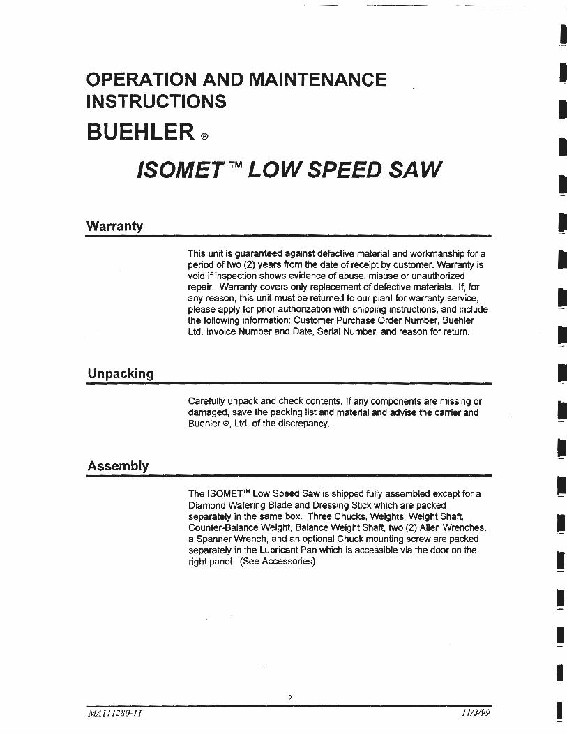
Operation and Maintenance Instructions
/SOMETTM Low Speed Saw
©1992 BUEHLER LTD. Printed in U.S.A.
r
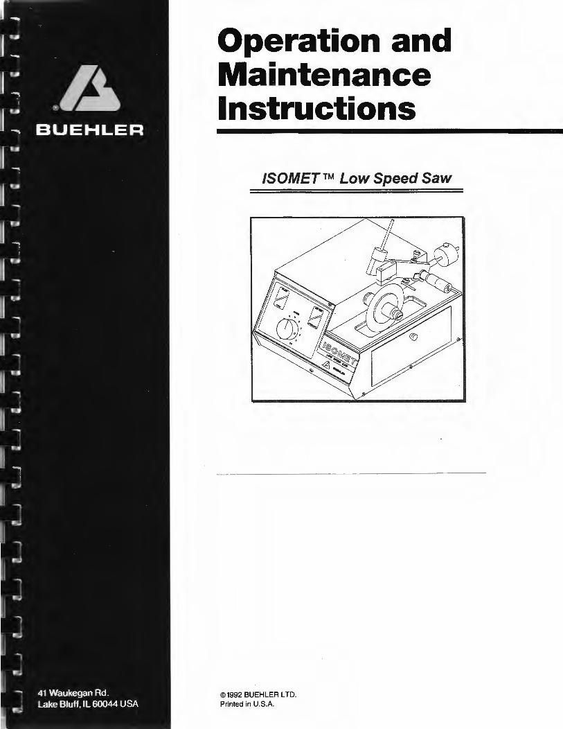
{})ecfaration of Conformity
Manufacturer: Of:
®A BUEHLER, Ltd.
41 Waukegan Road Lake Bluff, Illinois 60044
Declares the following product: /SOMET n.t LOW SPEED SAW
To be in accordance with EC Directive(s);
Safety of Machinery: EMC Directive:
89/392/EEC and 91/368/EEC and 93/44/EEC according to the following standards:
89/336/EEC and 92/231/EEC according to the following standards:
EN 292 PART 1 1991 EN 292 PART 2 1991 EN 60204 PART 1 1993
Position: Director of Engineering
Name: Chuck Motley
Signature:
Cliuc~9rtotfey
EN 50081-1: 1992 EN 50082-1: 1992
Date: 111197
This Manual is a custom generated document. It includes all revisions relative to this specific Buehler item as of the date shown below.
MA111280-11 1113/99
I I I I I I I I I I I I I I I I I I I
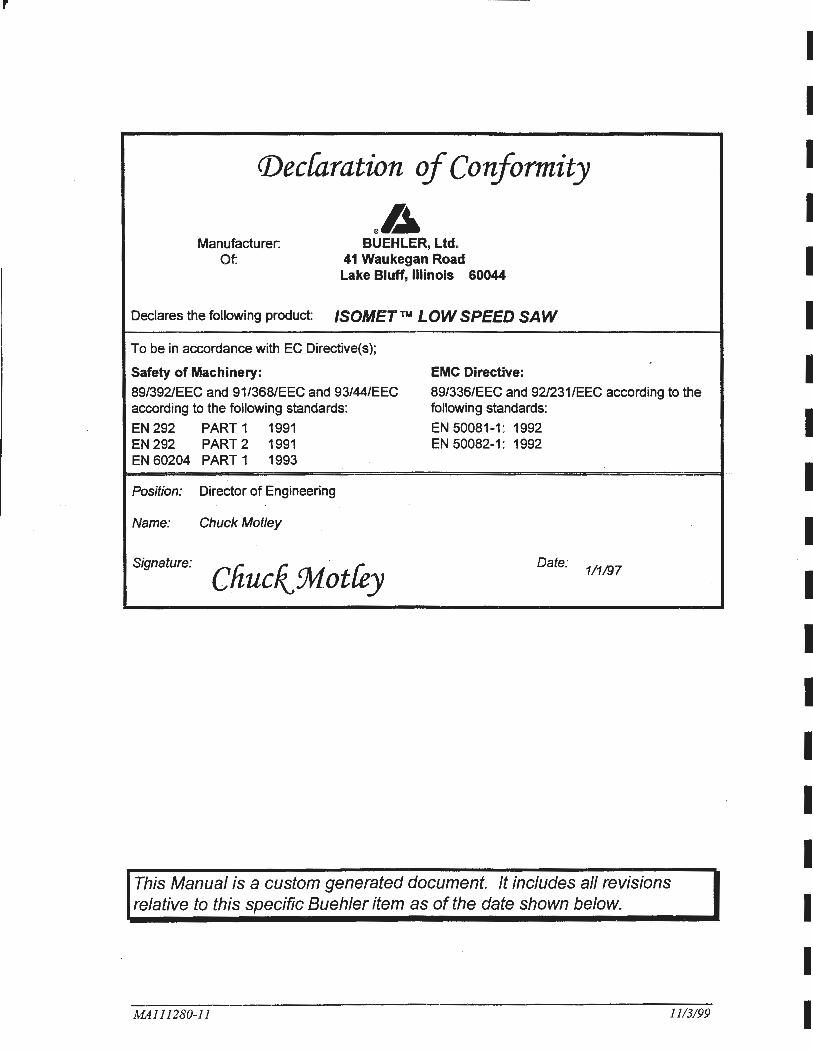
TABLE OF CONTENTS
DESCRIPTION PAGE
Warranty ....................................................................................................................................... 2
Unpacking ................................................... ................... ... ............................................... ..... ....... 2
Assembly ...................................................................................................................................... 2
Installation .................................................................................................................................... 3
Location ............ ........ .. .............. ........ ........................................ .. .... ................................. 3
Electrical ......................................... ..... .......... .................................................................. 3
Blade Installation ............................................................................................................. 4
Lubrication .......... .......... .................................................................................................. ............. . 5
Operation .... ..... ..................................................... .... ............. ............ ... ........................................ 6
Loading the Saw ........................................................................................... .... ............... 6
Adjustment of Cut-Off Switch Mechanism ....................................................................... 6
Micrometer Adjustment and Weight Selection ................................................................ 7
Cutting the Specimen ........................................ .............................................................. 7
Maintenance ..... .......... .. ....................... ... ......... ...... ........................................................................ 9
Motor or Drive Belt Replacement ............................. ....................................................... 9
Micrometer Screw Adjustment .... ................... .......... ..... ...................... ... ... ~ ..................... 11
Replacement or Exchange of Micrometers ..................................................................... 11
General Specifications ........ ........ ........................... ......... ... .. ...... ... .... ..... ..... .................... 12
Hot Cell or Glove Box Use ....... .................................................................................................... 12
Exploded Assembly Drawings .................................................. ........... .... .......... ........................ ... 13
Electrical Connection Drawing ........................................ ... .... ..... ...... .... ....................................... 20
Packaging Drawing ........................................ .......... .. ......................... .. ....................................... 21
Parts List ................................................ ... ....................... ............................................................ 22
Accessories and Supplies ..................................................................................... · ....................... 24
ISOCUT ®Wafering Blades ................ ............... ............... ... ... .... .................. .. .. ......... ....... 26
Notes: ...................................................... .. ...................... ............................................................. 28
MA111280-11 1113199
----- -- - ------ ----------------------------------------
OPERATION AND MAINTENANCE INSTRUCTIONS
BUEHLER® ISOMET™ LOW SPEED SAW
Warranty
Unpacking
Assembly
MA111280-11
This unit is guaranteed against defective material and workmanship for a period of two (2) years from the date of receipt by customer. Warranty is void if inspection shows evidence of abuse, misuse or unauthorized repair. Warranty covers only replacement of defective materials. If, for any reason, this unit must be returned to our plant for warranty service, please apply for prior authorization with shipping instructions, and include the following information: Customer Purchase Order Number, Buehler Ltd. Invoice Number and Date, Serial Number, and reason for return.
Carefully unpack and check contents. If any components are missing or damaged, save the packing list and material and advise the carrier and Buehler®, Ltd. of the discrepancy.
The ISOMErrM Low Speed Saw is shipped fully assembled except for a Diamond Wafering Blade and Dressing Stick which are packed separately in the same box. Three Chucks, Weights, Weight Shaft, Counter-Balance Weight, Balance Weight Shaft, two (2) Allen Wrenches, a Spanner Wrench, and an optional Chuck mounting screw are packed separately in the Lubricant Pan which is accessible via the door on the right panel. (See Accessories)
2
1113/99 I
Installation
MA111280-11
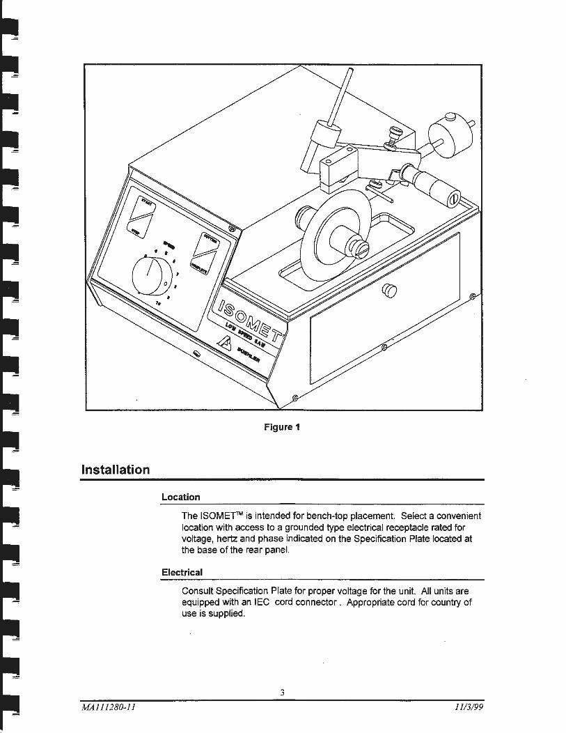
Figure 1
Location
The ISOME"fTM is intended for bench-top placement. Select a convenient location with access to a grounded type electrical receptacle rated for voltage, hertz and phase indicated on the Specification Plate located at the base of the rear panel.
Electrical
Consult Specification Plate for proper voltage for the unit. All units are equipped with an IEC cord connector . Appropriate cord for country of use is supplied.
3
1113/99
MA111280-11
Blade Installation
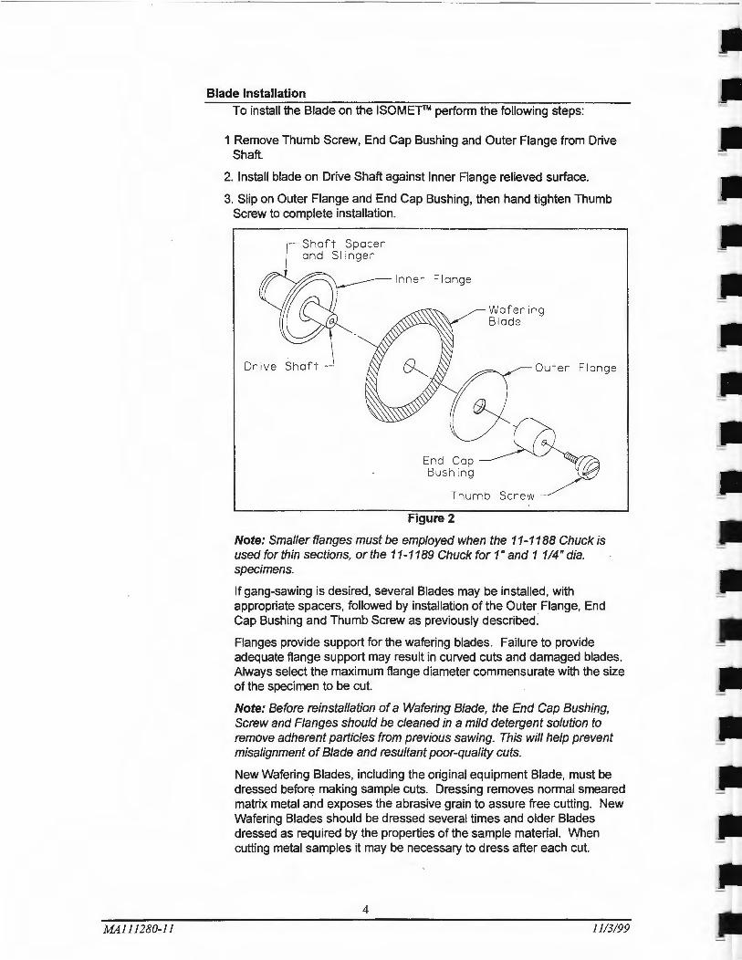
To install the Blade on the ISOMETTM perform the following steps:
1 Remove Thumb Screw, End Cap Bushing and Outer Flange from Drive Shaft.
2. Install blade on Drive Shaft against Inner Flange relieved surface.
3. Slip on Outer Flange and End Cap Bushing, then hand tighten Thumb Screw to complete installation.
Drive Shaft
Waf ering Bl ade
Outer Flange
Thumb Screw
Figure 2
Note: Smaller flanges must be employed when the 11-1188 Chuck is used for thin sections, or the 11-1189 Chuck for 1" and 1 114" dia. specimens.
If gang-sawing is desired, several Blades may be installed, with appropriate spacers, followed by installation of the Outer Flange, End Cap Bushing and Thumb Screw as previously described.
Flanges provide support for the wafering blades. Failure to provide adequate flange support may result in curved cuts and damaged blades. Always select the maximum flange diameter commensurate with the size of the specimen to be cut.
Note: Before reinstallation of a Wafering Blade, the End Cap Bushing, Screw and Flanges should be cleaned in a mild detergent solution to remove adherent particles from previous sawing. This will help prevent misalignment of Blade and resultant poor-quality cuts.
New Wafering Blades, including the original equipment Blade, must be dressed before making sample cuts. Dressing removes normal smeared matrix metal and exposes the abrasive grain to assure free cutting. New Wafering Blades should be dressed several times and older Blades dressed as required by the properties of the sample material. When cutting metal samples it may be necessary to dress after each cut.
4
11/3/99
Lubrication
MA111280-11
To dress, position the Dressing Stick in the 11-1187 Saddle Chuck and make thin transverse cuts through the Dressing Stick, or use a 11-1196 ISOMETTM Dressing Chuck. (See Accessories) Use of this device permits dressing to be performed without removing a previously fixtured sample.
CAUTION - Feeding the Dressing Stick or any sample materials manually into the Blade could result in damage to the Blade.
The ISOMETTM employs the "drag" principle of lubrication with the lubricant carried to the sample on the periphery of the Blade. ISOCUT® Fluid reduces cutting time and produces superior quality cuts. Its use promotes effective lubrication which allows the diamond particles to cut cleanly. It minimizes Blade loading by the formation of discrete chips and effects their clean release from the Blade and work surface.
Fill the Lubricant Pan with 11-1193-032 ISOCUT® Fluid to a level that will immerse Blade approximately 1/4". ISOCUT® Fluid is best for most metals and many non-metals. When the lubricant becomes contaminated with sludge it should be discarded and replaced.
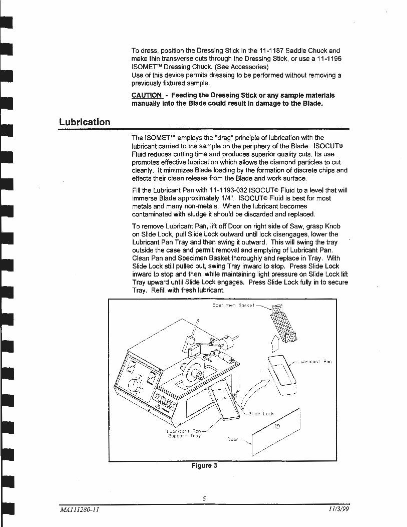
To remove Lubricant Pan, lift off Door on right side of Saw, grasp Knob on Slide Lock, pull Slide Lock outward until lock disengages, lower the Lubricant Pan Tray and then swing it outward. This will swing the tray outside the case and permit removal and emptying of Lubricant Pan. Clean Pan and Specimen Basket thoroughly and replace in Tray. With Slide Lock still pulled out, swing Tray inward to stop. Press Slide Lock inward to stop and then, while maintaining light pressure on Slide Lock lift Tray upward until Slide Lock engages. Press Slide Lock tully in to secure Tray. Refill with fresh lubricant.
Door
Figure 3
5
11/3/99
Operation
Loading the Saw
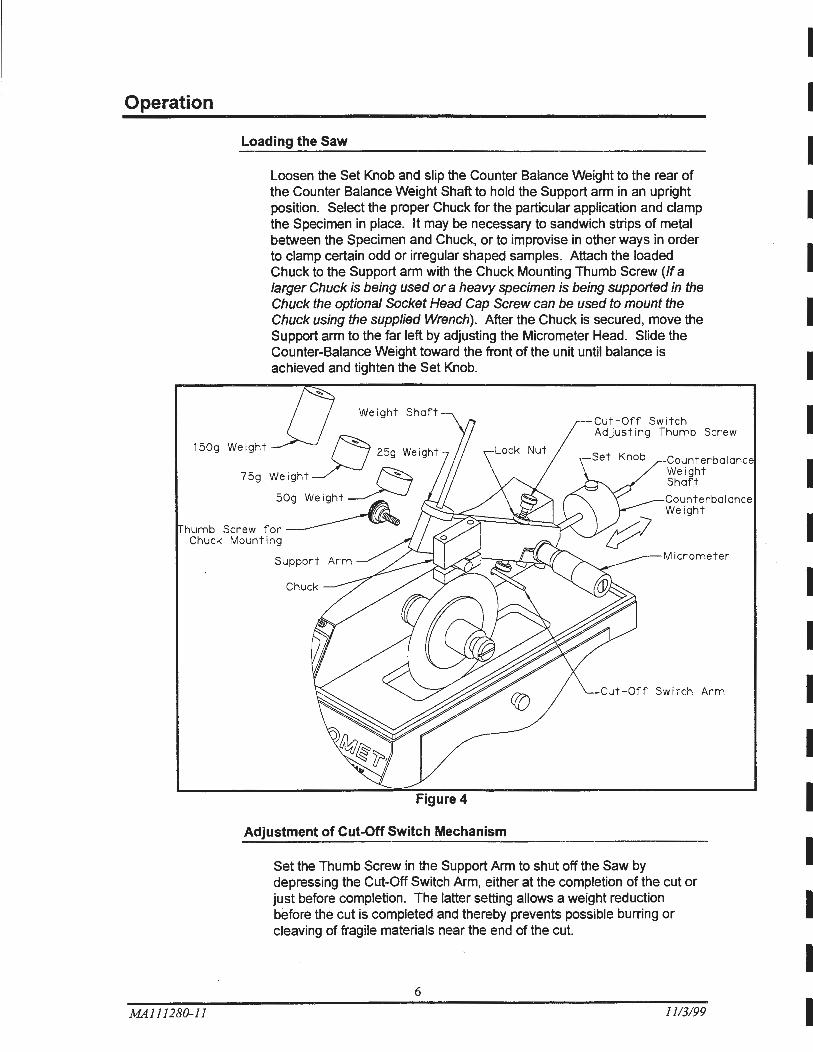
Loosen the Set Knob and slip the Counter Balance Weight to the rear of the Counter Balance Weight Shaft to hold the Support arm in an upright position. Select the proper Chuck for the particular application and clamp the Specimen in place. It may be necessary to sandwich strips of metal between the Specimen and Chuck, or to improvise in other ways in order to clamp certain odd or irregular shaped samples. Attach the loaded Chuck to the Support arm with the Chuck Mounting Thumb Screw (If a larger Chuck is being used or a heavy specimen is being supported in the Chuck the optional Socket Head Cap Screw can be used to mount the Chuck using the supplied Wrench) . After the Chuck is secured, move the Support arm to the far left by adjusting the Micrometer Head. Slide the Counter-Balance Weight toward the front of the unit until balance is achieved and tighten the Set Knob.
Weight Shaft
150g Weight .J ~ 25g Weight
75g Weight____>--J ~ 50g Weight__;>-..}
Cut-Off Switch Adjusting Thumb Screw
Counterbalanc Weight Shaft
humb Screw for~ Counterbalance Weight
Chuck Mounting
MA111280-11
Support Micrometer
Cut - Off Switch Arm
Adjustment of Cut-Off Switch Mechanism
Set the Thumb Screw in the Support Arm to shut off the Saw by depressing the Cut-Off Switch Arm, either at the completion of the cut or just before completion. The latter setting allows a weight reduction before the cut is completed and thereby prevents possible burring or cleaving of fragile materials near the end of the cut.
6
11/3/99
I I I I I I I I I I I I I I I I I I I
MA111280-11
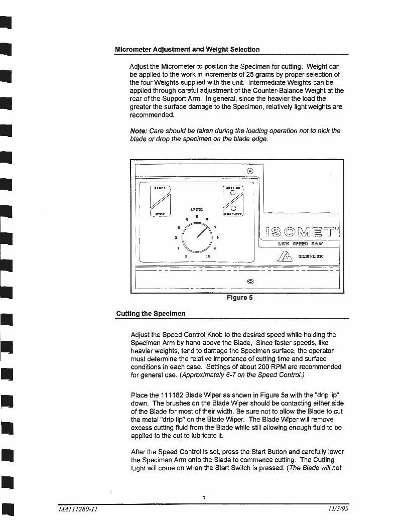
Micrometer Adjustment and Weight Selection
Adjust the Micrometer to position the Specimen for cutting. Weight can be applied to the work in increments of 25 grams by proper selection of the four Weights supplied with the unit. Intermediate Weights can be applied through careful adjustment of the Counter-Balance Weight at the rear of the Support Arm. In general, since the heavier the load the greater the surface damage to the Specimen, relatively light weights are recommended.
Note: Care should be taken during the loading operation not to nick the blade or drop the specimen on the blade edge.
®
[;1 [Y ~ II!L"Il!lm ~ 5 dil I
·:0:· D~@~~UTM &.©W !;Iii"~~@ @fA W
.~I:Jil.Jlll!:IXJIL.Il!llll 0 10
@
. F1gure 5
Cutting the Specimen
Adjust the Speed Control Knob to the desired speed while holding the Specimen Arm by hand above the Blade, Since faster speeds, like heavier weights, tend to damage the Specimen surface, the operator must determine the relative importance of cutting time and surface conditions in each case. Settings of about 200 RPM are recommended for general use. (Approximately 6-7 on the Speed Control.)
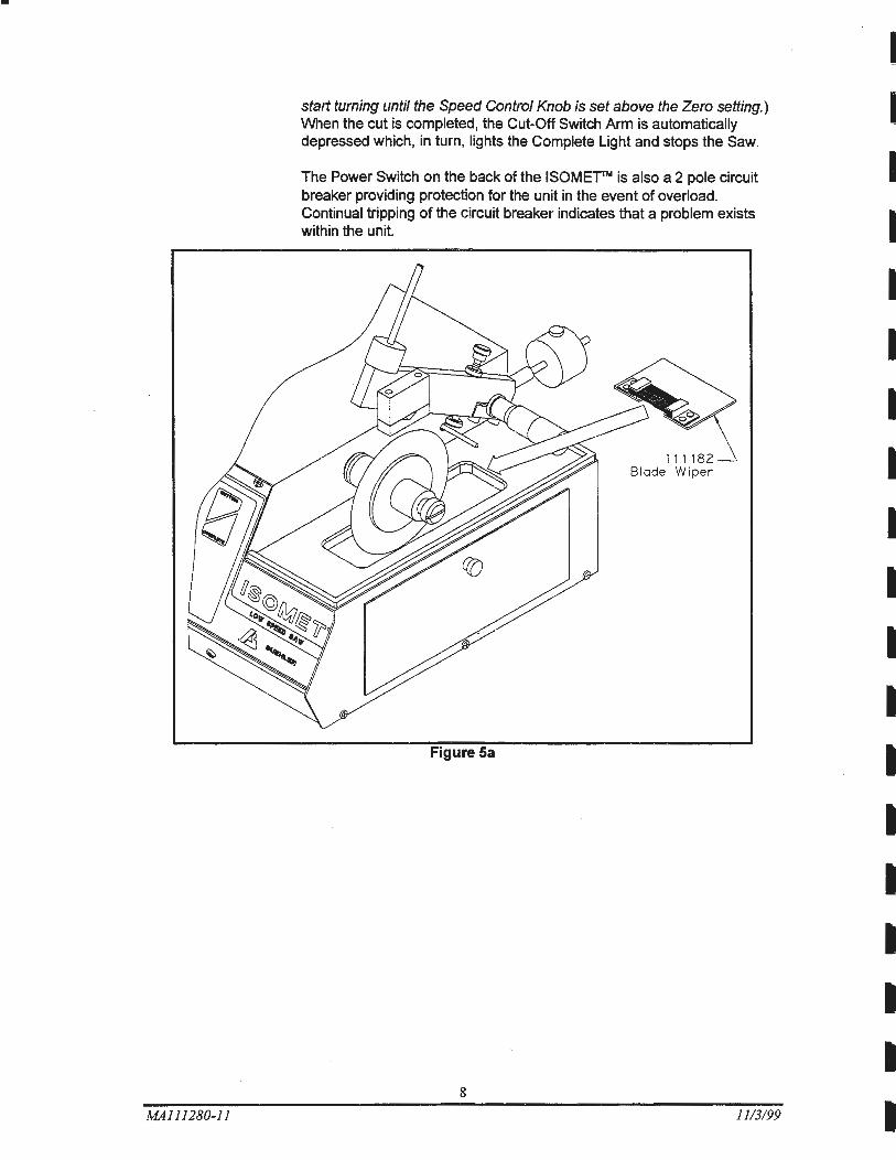
Place the 111182 Blade Wiper as shown in Figure Sa with the "drip lip" down. The brushes on the Blade Wiper should be contacting either side of the Blade for most of their width. Be sure not to allow the Blade to cut the metal "drip lip" on the Blade Wiper. The Blade Wiper will remove excess cutting fluid from the Blade while still allowing enough fluid to be applied to the cut to lubricate it.
After the Speed Control is set, press the Start Button and carefully lower the Specimen Arm onto the Blade to commence cutting. The Cutting Light will come on when the Start Switch is pressed. (The Blade will not
7
11/3/99
•
MAl 11280-11
start turning until the Speed Control Knob is set above the Zero setting.) When the cut is completed, the Cut-Off Switch Arm is automatically depressed which, in turn, lights the Complete Light and stops the Saw.
The Power Switch on the back of the ISOMEf'TM is also a 2 pole circuit breaker providing protection for the unit in the event of overload. Continual tripping of the circuit breaker indicates that a problem exists within the unit.
Figure Sa
8
111182 Blade Wiper
1113199
I I I I I I I I I I I I I I I I I I
Maintenance
CAUTION-
DO NOT PERFORM ANY REPAIRS OR ADJUSTMENTS FOR A PERIOD OF TWO (2) YEARS. WARRANTY IS VOID IF INSPECTION SHOWS EVIDENCE OF ABUSE OR UNAUTHORIZED REPAIR.
The ISOMETTM Saw is designed and built to require very little service. The sealed ball bearings of the Drive Shaft and Micrometer Shaft and the sealed continuous duty Motor require no lubrication.
If Maintenance is required, first disconnect unit from electrical power source.
Motor or Drive Belt Replacement
MA111280-11
Spacer
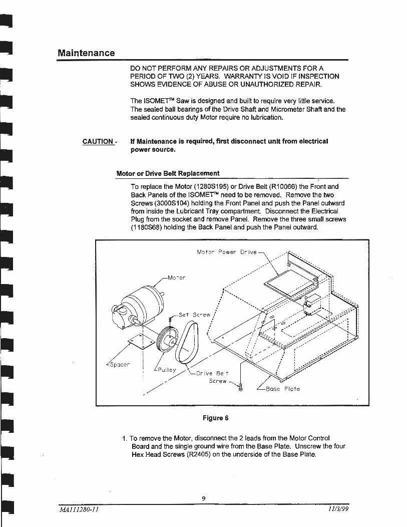
To replace the Motor (1280S195) or Drive Belt (R10066) the Front and Back Panels of the ISOMETN need to be removed. Remove the two Screws (3000S104) holding the Front Panel and push the Panel outward from inside the Lubricant Tray compartment. Disconnect the Electrical Plug from the socket and remove Panel. Remove the three small screws ( 1180S68) holding the Back Panel and push the Panel outward.
Motor Power Drive
Motor
Base Plate
Figure 6
1. To remove the Motor, disconnect the 2 leads from the Motor Control Board and the single ground wire from the Base Plate. Unscrew the four Hex Head Screws (R2405) on the underside of the Base Plate.
9
11/3/99
MA111280-11
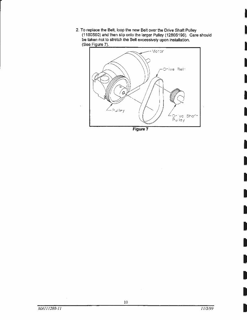
2. To replace the Belt, loop the new Belt over the Drive Shaft Pulley (1180S60) and then slip onto the larger Pulley (1280S196). Care should be taken not to stretch the Belt excessively upon installation. (See Figure 7).
Pulley
Figure 7
10
Dr ive Belt
Or ive Shaft Pulley
11/3/99
I I
I I I I I
I I I I I
MA111280-ll
Micrometer Screw Adjustment
To clean or adjust the Micrometer Screw Assembly, perform the following steps:
1. Remove the End Screw with a thin blade screwdriver.
2. Loosen the Thimble by tapping against the end of the Thimble with a plastic hammer or screwdriver handle.
3. Carefully remove the Thimble from the Shaft.
4. Clean the exposed assembly with a grease solvent to remove gummy residues and contaminant particles.
5. To adjust Micrometer Screw Drag attach the provided Spanner Wrench to the hole in the Adjusting Nut. Turn counterclockwise to loosen, clockwise to tighten the drag.
6. Lubricate the assembly with #1620 Starrett Tool and Instrument Oil or equivalent.
7. Reinstall by first lining up the 0 line on the Thimble with the graduated index line on the Sleeve.
8. Tighten the End Screw while holding the Thimble in place.
Replacement or Exchange of Micrometers
It is necessary to remove the exterior case of the ISOMETTM to replace the Micrometer or interchange English and Metric Scale Micrometers. The following procedure should be used:
1. Unplug unit from electrical power source.
2. Remove Shaft Thumb Screw, End Cap Bushing, Flanges, Blade and Spacer.
3. Remove Arm Assembly by removing two (2) Screws that hold Clamp to Arm.
4. Remove Micrometer Thimble by following steps 1-3 under Micrometer Screw Adjustment.
5. Remove Lubricant Pan with Basket by swinging out Support Tray.
6. Remove six Screws (three on each side) attaching Case to Base Plate.
7. Remove two Front Screws, pull off Front Panel and disconnect Electrical Plug.
8. Pull Rear Panel backward after removing the three Rear Screws. The Rear Panel should not be completely detached from the unit (wires should remain connected) but can be pulled far enough back to allow the Case to clear.
9. Tip the case toward the Shaft side and slide over Shaft, Micrometer Spindle, and Cut-Off Switch Arm.
Reassemble in reverse sequence taking care not to pinch electrical wires or bend the Micrometer Spindle, the Cut-Off Switch Arm, or the precision Blade Shaft.
II
1113/99
General Specifications:
1. Tested sound level pressure less than 70 db.
Hot Cell or Glove Box Use
MAl 11280-11
When the ISOMETTM is used in a Hot Cell or Glove Box, the inert atmosphere may cause excessive motor brush wear. Brushes may need to be replaced as often as once a month. Such replacement is not covered by the Warranty
12
1113199
I
I
I
I
I
I
I
I
I
I
I
I
I
I
I
I
I
I
I
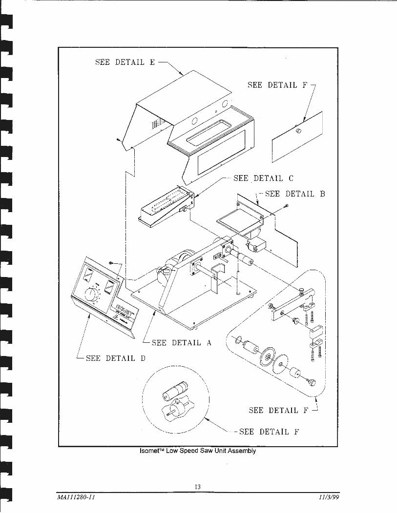
SEE DETAIL E
SEE DETAIL F
SEE DETAIL B
lsomet™ Low Speed Saw Unit Assembly
13
MA111280-11 1113199
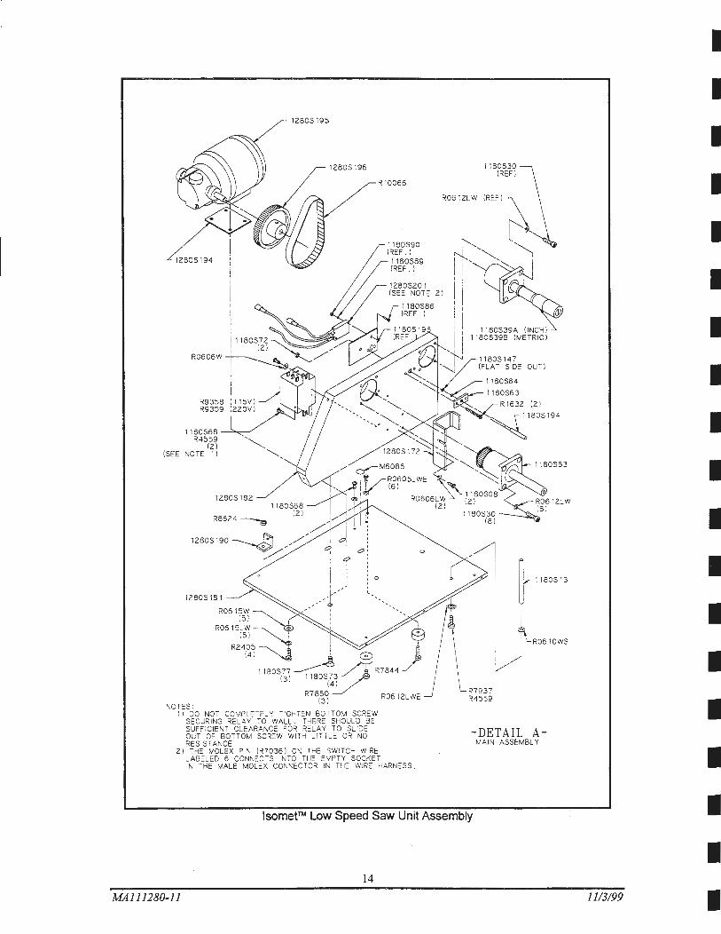
1180S68 R4559
{2) {SEE NOTE 1)
1280S181
NOTES :
1280S195
R7850 {3)
11 DO NOT COMPLETELY TIGHTEN BOTTOM SCREW SECURING RELAY TO WALL. THERE SHOULD BE SUFFICIENT CLEARANCE FOR RELAY TO SLIDE OUT OF BOTTOM SCREW WITH L ITTLE OR NO RESISTANCE.
R10066
2) THE MOLE X PIN (R7036} ON THE SWITCH WIRE LABELED 5 CONNECTS INTO THE EMPTY SOCKET IN THE MALE MOLE X CONNECTOR IN THE WIRE HARNESS .
R0612LW
1180S30 {REF I
OUT)
{21
-DETAIL A-MAIN ASSEMBLY
lsomet™ Low Speed Saw Unit Assembly
14
MA111280-11
I
I
I
I
I
I
I
I
I
I
I
I
I
I
I
I
I
I 11/3199 I
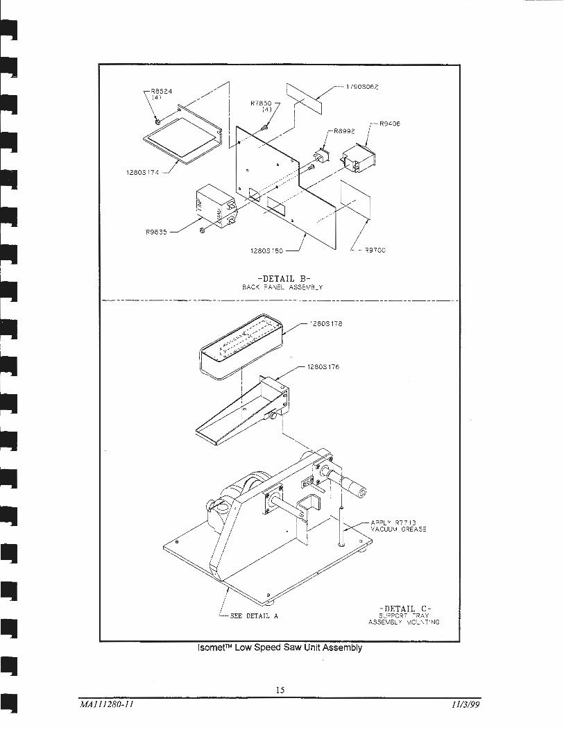
R8624 (4)
1280S174
R9835
MA111280-11
1280S180
-DETAIL BBACK PANEL ASSEMBLY
1280S178
1280S176
lsometTM Low Speed Saw Unit Assembly
15
R9700
APPLY R7713 VAC UUM GREASE
-DETAIL CsuPPORT TRAY
ASSEMBLY MOUNTING
1113/99
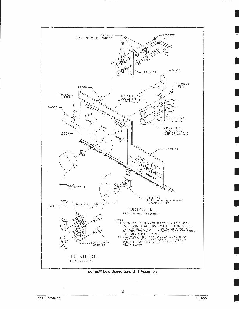
(PART OF WIRE
R9354 (SEE NOTE 1 J
R0585 (2 1
(SEE NOTE 2 1 CONNECTOR FROM
WIRE 31
-DETAIL Dl -LAMP MOUNTING
I
J R9351 (115VJ R9352 1250V J
(SEE DETAIL D 1 I
1280S 168 ~R8370
A 1180S72 1280S 169 I REF I
1280S 173
R9349 (1 15V) R9350 (250V I I SEE DETAIL D 1 J
1280S167
(PART OF WIRE HARNESS J (1 280S175 REF )
-DETAIL D-FRONT PANEL ASSEMBLY
NOT ES : I) WHE N MOUNT ING KNOB IR9354 ) ONTO SWITCH
POT I 1280S 1751 TURN SWITCH POT COUNTER CLOCKWISE TO STOP. THEN ALIGN KNOB TO 0 (ZERO ) ON PANEL. TIGHTEN KNOB SET SCREW TO LOCK KNOB IN PLACE.
2) USE R0585 TIE WRAP AROUND MIDPOINT OF LAMP TO SECURE WIRE LEADS TO PREVENT WIRES FROM TOUCHING BELT AND PULLEY (BOT H LAMPS I
lsomet™ Low Speed Saw Unit Assembly
16
MA111280-ll 11/3/99
I
I
I
I
I
I
I
I
I
I
I
I
I
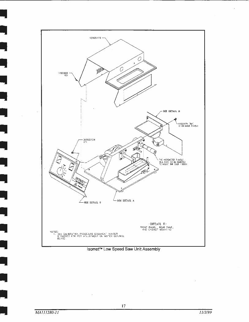
1180568 (61
NOTES o
12805179
SEE DETAIL A SEE DETAIL D
I SEE CAL IBRATION PROCEDURE DOCUMENT NUMBER 610W0020 FOR POT ADJUSTMENT ON MOTOR CONTROL BOARD
SEE DETAIL B
THE MICROMETER THIMBLE WILL HAVE TO BE REMOVED TO MOUNT THE CASE II 80S I
-DETAIL EFRONT PANEL. REAR PANEL
AND CABINET MOUNTING
lsometTM Low Speed Saw Unit Assembly
17
MA111280-11 11/3/99
I
I i I
I I
SEE DETAIL E l
6.
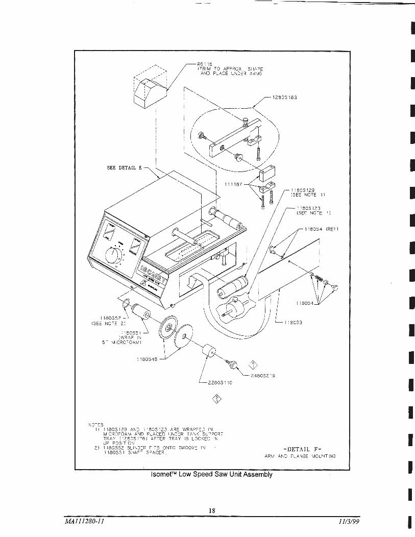
NOTES:
R6116 (TRIM TO APPROX . SHAPE
AND PLACE UNDER ARM)
-~,~""" L228,,,
I } 1180S 129 AND I I 80S 123 ARE WRAPPED IN MICROFOAM AND PLACED UNDER TANK SUPPORT TRAY I1280S176} AFTER TRAY IS LOCKED IN UP POSIT ION
2} 1180S52 SLINGER FITS ONTO GROOVE IN I 180S51 SHAFT SPACER .
1180S129 I SEE NOTE 1 l
1)
1 180S4 I REF l
1180S3
-DETAIL F-ARM AND FLANGE MOUNTING
lsometTM Low Speed Saw Unit Assembly
18
MAl 11280-11
I
I
I
I
I
I
I
I
I
I
I
I
I
I
I
I
I
I 1113/99 I
II II II II II
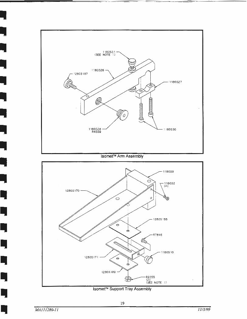
12805170
II II II II II II II MAJ11280-Jl
1180531 (SEE NOTE 1 l
1180526
1180528 R4559
lsomet™ Arm Assembly
12805171
12805189
lsomet™ Support Tray Assembly
19
1180527
1180530
118059
12805188
1180510
1)
1113/99
~ ....... ....... ....... ~ 'P ....... .......
.......
....... ~ ~ '0
N 0
I_
iii 0 3 (1)
1 r
~ en "0 (1)
~ (/) Ill ~ m ro g. :::::! . 0 ~ () 0 :::l :::l (1) 0 ::::r. 0 :::l
0 or (Q
iil 3
I_.
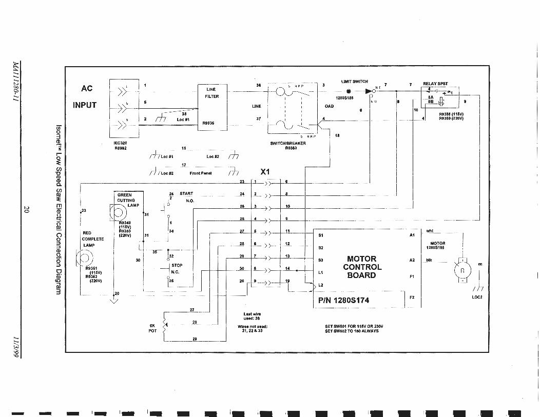
AC ~>L
I PUT f-j: G
f----1: N
IEC320 R8992
GREEN CUTTING
23 l B!..LAMP
~9349 (115V)
RED R9350 (220V)
COMPLETE
LAMP I
~. 30
(115V) R9352
(220V)
20
I~ I~ t-
1 LINE
FILTER 5
2 ~ 7 Locll1 R9835
15
/h locll1 Locll2
17
rf7 tocll2 Front Panel
24 START
l2 N.O.
j : 31
35 ~ 32
STOP -
N.C.
~ 26
27
~. 28
OK t POT
29
I~ ,_ 1-
LIMIT SWITCH 7 RELAYSPST 36 5 R N P 3 7 .... .. "~N [ 4 - ..... ? .... "'1
I I 12805185 &A n
I I N a a ~ 9 LINE I I OAD
I I 8 10
41 I I R9358 (115V)
37 I I 4 R9359 (220V) I - "'-5 A HP 18
SWITCH/BREAKER R9363
1--h 1--h X1
23 6
24 2 8
25 3 10
28 4 I
27 5 11 whl 51 A1
28 8 12 MOTOR 52 12805195
29 7 13 MOTOR
0-' S3 A2 blk
14 CONTROL 30 8 l1 BOARD F1
20 ~>-4 "--[> l2
II
P/N 12805174 I F2 LOC:
Laatwlre uaed: 38
Wires not uaed: SET SW501 FOR 115V OR 230V 21, 22&33 SET SW502 TO 180 ALWAYS
1- 1- '• '• '• '• ,. ,. I. ,. ,.
Ill
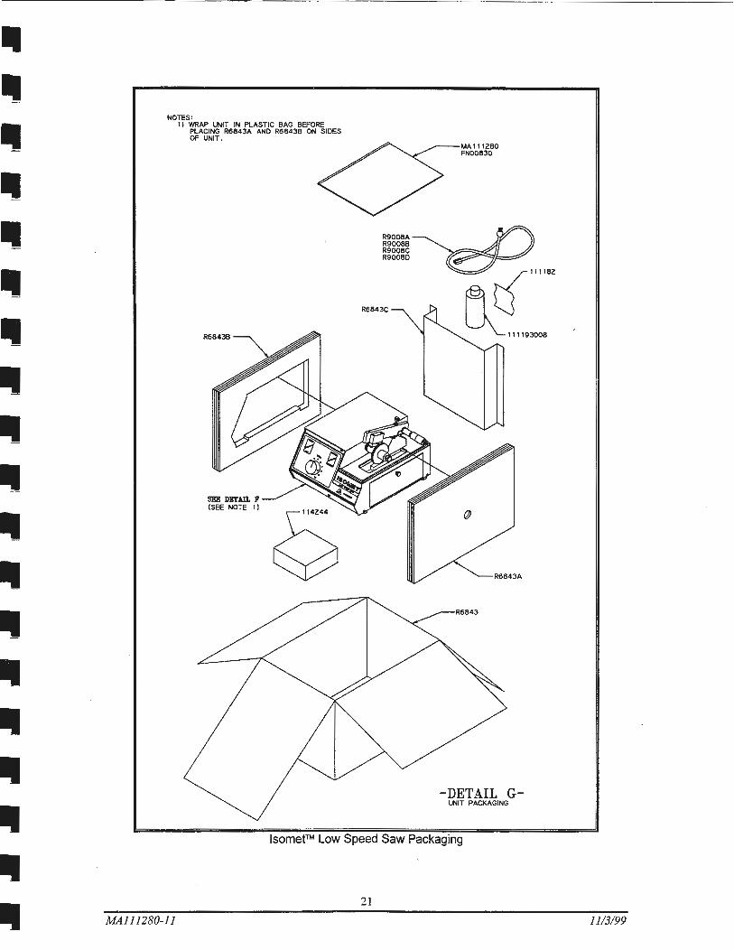
NOTES: 1) WRAP UNIT IN PLASTIC BAG BEFORE
PLACING R6843A AND R6843B ON SIDES OF UNIT.
R68438
SEE DETAIL F !SEE NOTE 1)
R9008A R900BB R9008C R90080
R6843C
MA1112BO FN00830
-DETAIL G-uNrT PACKAGING
lsomet™ Low Speed Saw Packaging
21
MAI/1280-11 11/3199
--- - ~
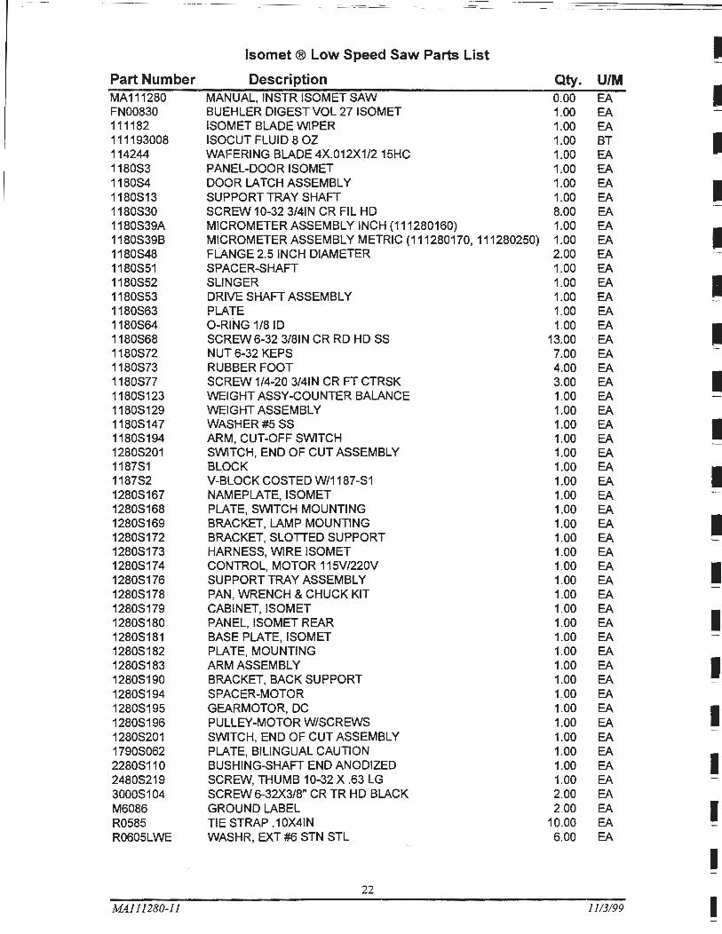
lsomet ® Low Speed Saw Parts List I Part Number Description Qty. U/M MA111280 MANUAL, INSTR ISOMET SAW 0.00 EA I FN00830 BUEHLER DIGEST VOL 27 ISOMET 1.00 EA 111182 ISOMET BLADE WIPER 1.00 EA 111193008 ISOCUT FLUID 8 OZ 1.00 BT I 114244 WAFERING BLADE 4X.012X1/2 15HC 1.00 EA 118053 PANEL-DOOR ISOMET 1.00 EA 118054 DOOR LATCH ASSEMBLY 1.00 EA I 1180513 SUPPORT TRAY SHAFT 1.00 EA 1180530 SCREW 10-32 3/41N CR FIL HD 8.00 EA 1180S39A MICROMETER ASSEMBLY INCH (111280160) 1.00 EA
I 1180S39B MICROMETER ASSEMBLY METRIC (111280170, 111280250) 1.00 EA 1180548 FLANGE 2.5 INCH DIAMETER 2.00 EA -1180551 SPACER-SHAFT 1.00 EA 1180552 SLINGER 1.00 EA I 1180553 DRIVE SHAFT ASSEMBLY 1.00 EA 1180563 PLATE 1.00 EA 1180564 0-RING 1/8 ID 1.00 EA I 1180568 SCREW 6-32 3/81N CR RD HD SS 13.00 EA 1180572 NUT 6-32 KEPS 7.00 EA 1180573 RUBBER FOOT 4.00 EA
I 1180577 SCREW 1/4-20 3/41N CR FT CTRSK 3.00 EA 11805123 WEIGHT ASSY-COUNTER BALANCE 1.00 EA 11805129 WEIGHT ASSEMBLY 1.00 EA 11805147 WASHER#5 SS 1.00 EA I 11805194 ARM, CUT-OFF SWITCH 1.00 EA 12805201 SWITCH, END OF CUT ASSEMBLY 1.00 EA 118751 BLOCK 1.00 EA I 118752 V-BLOCK COSTED W/1187 -51 1.00 EA 12805167 NAMEPLATE, ISO MET 1.00 EA -12805168 PLATE, SWITCH MOUNTING 1.00 EA
I 12805169 BRACKET, LAMP MOUNTING 1.00 EA 12805172 BRACKET, SLOTTED SUPPORT 1.00 EA 12805173 HARNESS, WIRE ISOMET 1.00 EA 12805174 CONTROL, MOTOR 115V/220V 1.00 EA I 12805176 SUPPORT TRAY ASSEMBLY 1.00 EA 12805178 PAN, WRENCH & CHUCK KIT 1.00 EA 12805179 CABINET, ISOMET 1.00 EA
I 12805180 PANEL, ISOMET REAR 1.00 EA 12805181 BASE PLATE, ISOMET 1.00 EA 12805182 PLATE, MOUNTING 1.00 EA 12805183 ARM ASSEMBLY 1.00 EA I 12805190 BRACKET, BACK SUPPORT 1.00 EA 12805194 SPACER-MOTOR 1.00 EA 12805195 GEARMOTOR, DC 1.00 EA I 12805196 PULLEY-MOTOR W/SCREWS 1.00 EA -12805201 SWITCH, END OF CUT ASSEMBLY 1.00 EA 17905062 PLATE, BILINGUAL CAUTION 1.00 EA
I 22805110 BUSHING-SHAFT END ANODIZED 1.00 EA 24805219 SCREW, THUMB 10-32 X .63 LG 1.00 EA 30005104 SCREW 6-32X3/8" CR TR HD BLACK 2.00 EA M6086 GROUND LABEL 2.00 EA I R0585 TIE STRAP .10X41N 10.00 EA R0605LWE WASHR, EXT#6 STN STL 6.00 EA
I -22
MAJ11280-11 11/3/99 I ......
Ill lsomet ® Low Speed Saw Parts List
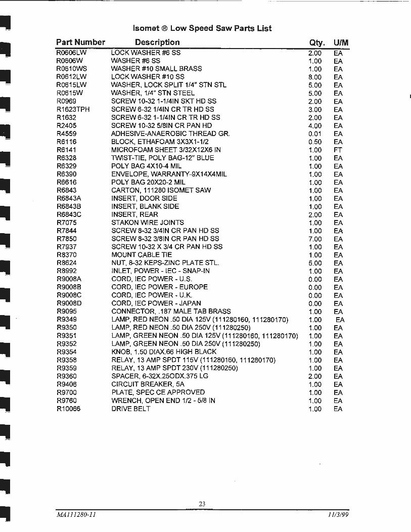
Part Number Description Qty. U/M R0606LW LOCK WASHER #6 SS 2.00 EA R0606W WASHER#6SS 1.00 EA
• R0610WS WASHER #1 0 SMALL BRASS 1.00 EA R0612LW LOCK WASHER #1 0 SS 8.00 EA R0615LW WASHER, LOCK SPLIT 1/4" STN STL 5.00 EA R0615W WASHER, 1/4" STN STEEL 5.00 EA R0969 SCREW 10-32 1-1/41N SKT HD SS 2.00 EA R1623TPH SCREW 6-32 1/41N CR TR HD SS 3.00 EA R1632 SCREW 6-32 1-1/41N CR TR HD SS 2.00 EA R2405 SCREW 10-32 5/81N CR PAN HD 4.00 EA R4559 ADHESIVE-ANAEROBIC THREAD GR. 0.01 EA R6116 BLOCK, ETHAFOAM 3X3X1-1/2 0.50 EA R6141 MICROFOAM SHEET 3/32X12X6 IN 1.00 FT R6328 TWIST-TIE, POLY BAG-12" BLUE 1.00 EA R6329 POLY BAG 4X10⁻⁴ MIL 1.00 EA R6390 ENVELOPE, WARRANTY -9X14X4MIL 1.00 EA
Ill R6616 POLY BAG 20X20-2 MIL 1.00 EA R6843 CARTON, 111280 ISOMET SAW 1.00 EA R6843A INSERT, DOOR SIDE 1.00 EA R6843B INSERT, BLANK SIDE 1.00 EA R6843C INSERT, REAR 2.00 EA R7075 STAKON WIRE JOINTS 1.00 EA R7844 SCREW 8-32 3/41N CR PAN HD SS 1.00 EA R7850 SCREW 8-32 3/81N CR PAN HD SS 7.00 EA R7937 SCREW 10-32 X 3/4 CR PAN HD SS 1.00 EA R8370 MOUNT CABLE TIE 1.00 EA
Ill R8624 NUT, 8-32 KEPS-ZINC PLATE STL. 5.00 EA R8992 INLET, POWER -IEC- SNAP-IN 1.00 EA R9008A CORD, IEC POWER - U.S. 0.00 EA R9008B CORD, IEC POWER - EUROPE 0.00 EA R9008C CORD, IEC POWER - U.K. 0.00 EA R9008D CORD, IEC POWER -JAPAN 0.00 EA R9095 CONNECTOR, .187 MALE TAB BRASS 1.00 EA R9349 LAMP, RED NEON .50 DIA 125V (111280160, 111280170) 1.00 EA R9350 LAMP, RED NEON .50 DIA 250V (111280250) 1.00 EA R9351 LAMP, GREEN NEON .50 DIA 125V(111280160, 111280170) 1.00 EA
Ill R9352 LAMP, GREEN NEON .50 DIA 250V (111280250) 1.00 EA R9354 KNOB, 1.50 DIAX.66 HIGH BLACK 1.00 EA R9358 RELAY, 13AMPSPDT115V(111280160, 111280170) 1.00 EA R9359 RELAY, 13 AMP SPOT 230V (111280250) 1.00 EA R9360 SPACER, 6-32X.250DX.375 LG 2.00 EA R9406 CIRCUIT BREAKER, SA 1.00 EA R9700 PLATE, SPEC CE APPROVED 1.00 EA
Ill R9760 WRENCH, OPEN END 1/2 - 5/8 IN 1.00 EA R10066 DRIVE BELT 1.00 EA
23
MA111280-ll 11/3/99
ACCESSORIES AND SUPPLIES FOR 11-1280 ISOMET TM LOW SPEED SAW
1 180S17
1 181SZ
R0965
1 18 1S 1
11 1 181
111189 111188
111194 111183
111195 111196
24
MA111280-11 11/3/99
I
I
I
I
I
I
I
I
I
I
I
I
I
I
I
I
I
I
I
II
II II II II II II
II II II
ACCESSORIES AND SUPPLIES FOR 11-1280 ISOMETTM LOW SPEED SAW
1 1 1 1 1 1
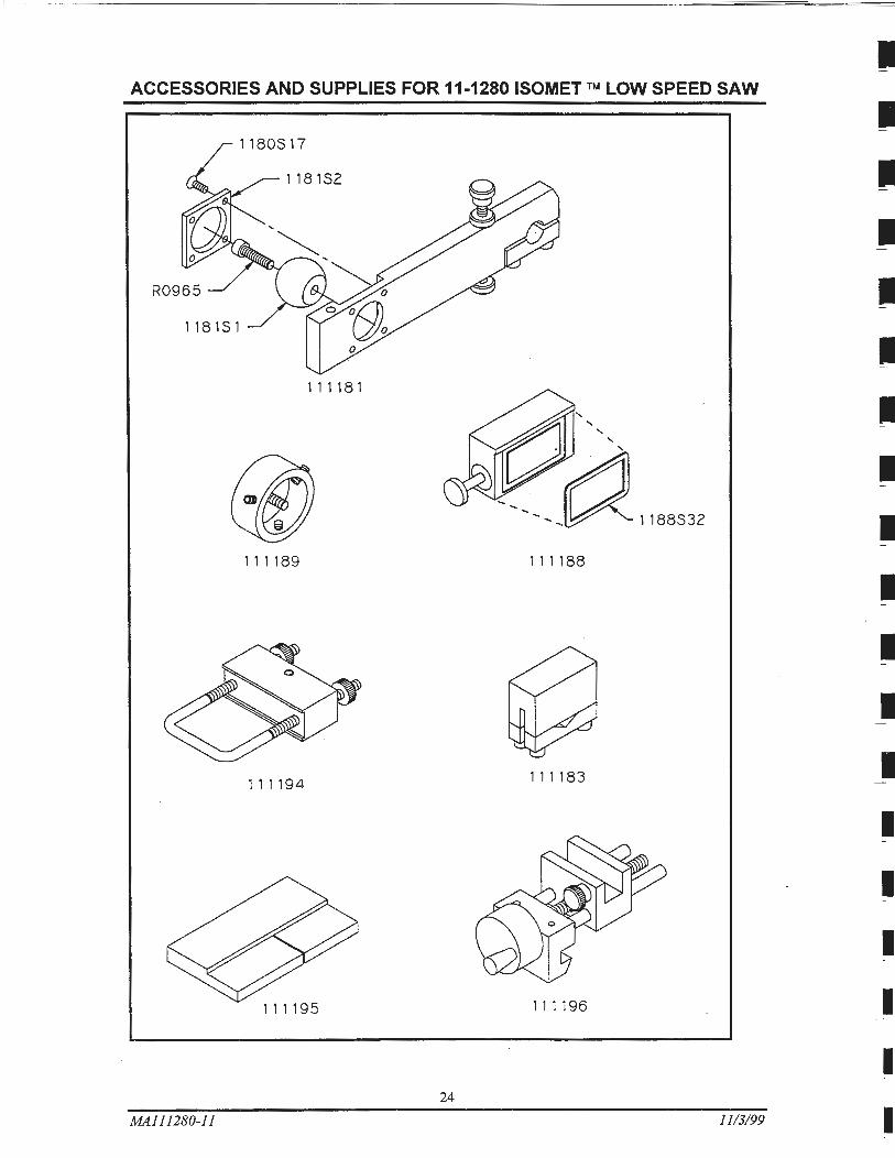
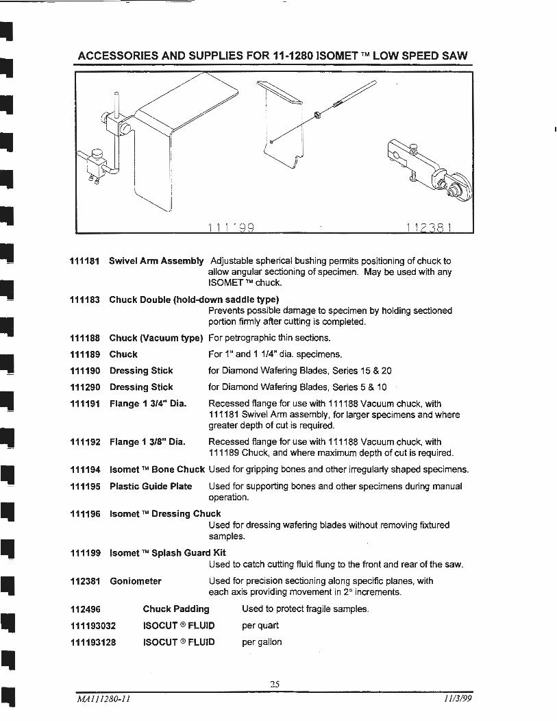
111181 Swivel Arm Assembly Adjustable spherical bushing perrrtits positioning of chuck to allow angular sectioning of specimen. May be used with any ISOMET ™ chuck.
111183 Chuck Double (hold-down saddle type) Prevents possible damage to specimen by holding sectioned portion firmly after cutting is completed.
111188 Chuck (Vacuum type) For petrographic thin sections.
111189 Chuck
111190 Dressing Stick
111290 Dressing Stick
111191 Flange 1 3/4" Dia.
111192 Flange 1 3/8" Dia.
For 1" and 1 1/4" dia. specimens.
for Diamond Wafering Blades, Series 15 & 20
for Diamond Wafering Blades, Series 5 & 1 0
Recessed flange for use with 111188 Vacuum chuck, with 111181 Swivel Arm assembly, for larger specimens and where greater depth of cut is required.
Recessed flange for use with 111188 Vacuum chuck, with 111189 Chuck, and where maximum depth of cut is required.
111194 lsomet rM Bone Chuck Used for gripping bones and other irregularly shaped specimens.
111195 Plastic Guide Plate Used for supporting bones and other specimens during manual operation.
111196 lsomet rM Dressing Chuck Used for dressing wafering blades without removing fixtured samples.
111199 lsomet ™ Splash Guard Kit Used to catch cutting fluid flung to the front and rear of the saw.
112381 Goniometer Used for precision sectioning along specific planes, with each axis providing movement in 2° increments.
112496
111193032
111193128
MA111280-11
Chuck Padding
ISOCUT ® FLUID
ISOCUT ® FLUID
Used to protect fragile samples.
per quart
per gallon
25
11/3/99
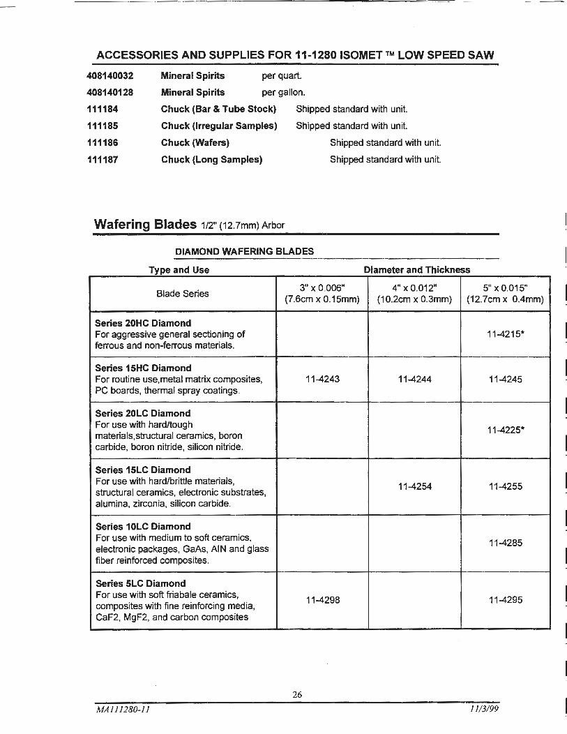
ACCESSORIES AND SUPPLIES FOR 11-1280 ISOMET TM LOW SPEED SAW
408140032
408140128
111184
111185
111186
111187
Mineral Spirits per quart.
Mineral Spirits per gallon.
Chuck (Bar & Tube Stock) Shipped standard with unit.
Chuck (Irregular Samples)
Chuck (Wafers)
Chuck (Long Samples)
Shipped standard with unit.
Shipped standard with unit.
Shipped standard with unit.
Wafering Blades 1/2" (12.7mm) Arbor
DIAMOND WAFERING BLADES
Type and Use Diameter and Thickness
Blade Series 3" x0.006" 4" X 0.012" 5" X 0.015"
(7.6cm x 0.15mm) (10.2cm x 0.3mm) (12.7cm x 0.4mm)
Series 20HC Diamond For aggressive general sectioning of 11-4215* ferrous and non-ferrous materials.
Series 15HC Diamond For routine use, metal matrix composites, 11-4243 11-4244 11-4245 PC boards, thermal spray coatings.
Series 20LC Diamond For use with hard/tough
11-4225* materials,structural ceramics, boron carbide, boron nitride, silicon nitride.
Series 15LC Diamond For use with hard/brittle materials,
11-4254 11-4255 structural ceramics, electronic substrates, alumina, zirconia, silicon carbide.
Series 1 OLC Diamond For use with medium to soft ceramics,
11-4285 electronic packages, GaAs, AI N and glass fiber reinforced composites.
Series SLC Diamond For use with soft friabale ceramics,
11-4298 11-4295 composites with fine reinforcing media, CaF2, MgF2, and carbon composites
26
MA111280-11 11/3/99
I
I I.
I ~
I
I
I
I
I
• Ill
Ill
II
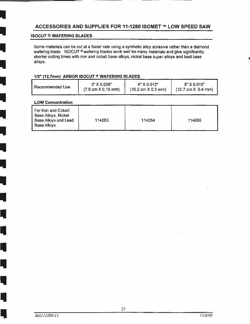
ACCESSORIES AND SUPPLIES FOR 11-1280 ISOMET TM LOW SPEED SAW
ISOCUT ®WAFERING BLADES
Some materials can be cut at a faster rate using a synthetic alloy abrasive rather than a diamond wafering blade. ISOCUT ®wafering blades work well for many materials and give significantly shorter cutting times with iron and cobalt base alloys, nickel base super alloys and lead base alloys.
1/2" (12.7mm) ARBOR ISOCUT ®WAFERING BLADES
Recommended Use 3" X0.006" 4" X 0.012" 5" X 0.015"
(7.6 em X 0.15 mm) (10.2 em X 0.3 mm) (12.7 em X 0.4 mm)
LOW Concentration
For Iron and Cobalt Base Alloys, Nickel Base Alloys and Lead 114263 114264 114265 Base Alloys
27
MAl 11280-11 11/3/99