Embed Size (px)
Citation preview

1
Power Pack series
OPERATION AND MAINTENANCE MANUAL

2
INTRODUCTION
JET CENTRAL produces the most advanced micro turbines available today: smaller, more powerful, faster acceleration, less fuel burn, lower temperatures, higher quality, less maintenance and the best price. JET CENTRAL, an ISO 9000 Company is a full production engine manufacturer, producing high quality parts to be assembled into the newest line of micro turbines.
We are committed to our turbines in a way never seen before. You won’t find a more knowledgeable company in micro turbines to turn than to JET CENTRAL.
3
TABLE OF CONTENTS
1 Safety Information......................................................................................................................... 5
1.1 Safety Rules ............................................................................................................................................. 7
2 Turbine System Components Description ............................................................................ 8 2.1 Parts List .................................................................................................................................................. 8 2.2 Turbine ..................................................................................................................................................... 9 2.3 POWERPACK / ECU ............................................................................................................................. 10 2.5 Kerostart System................................................................................................................................. 11 2.6 Hand data Terminal (HDT) ............................................................................................................. 12
3 Turbine System Installation Instructions .......................................................................... 13 3.1 POWERPACK / ECU ............................................................................................................................. 13 3.2 Pump/Starter Battery ....................................................................................................................... 15 3.3 Radio Receiver ..................................................................................................................................... 15 3.4 Fuel Pump Line out ............................................................................................................................ 15
4 Programming the POWERPACK / ECU ................................................................................. 16
4.1 First Screen......................................................................................................................................................... 17
4.2 Main Screen........................................................................................................................................... 17 4.3 Secondary Screen................................................................................................................................ 17 4.4 Menu Screen ......................................................................................................................................... 17 4.6 Info Submenu ....................................................................................................................................... 19 4.7 Radio Submenu.................................................................................................................................... 21
4.8 Transmitter Setup .................................................................................................................... 21
4.8.1 Transmitter Preparation and Verification. ....................................................................................... 21 4.8.2 Throttle Curves ............................................................................................................................................ 23
4.9 Run Submenu ....................................................................................................................................... 24

4
4.10 Last Run Reason................................................................................................................................ 25
5 Radio Link Failsafe ..................................................................................................................... 26
6 Starting the engine ..................................................................................................................... 27
6.2.1 Preparing the turbine for running ....................................................................................................... 27 6.2.2 Important notes for kerostart turbines ............................................................................................. 27 6.2.3 First engine runs.......................................................................................................................................... 28 6.2.4. Priming the fuel system ........................................................................................................................... 28 6.2.5 Starting the engine...................................................................................................................................... 29 6.2.6 Engine shut down procedure ................................................................................................................. 30
6.3 List of POWERPACK / ECU message codes ................................................................................. 31
7 Fuel and Fuel System Care ....................................................................................................... 32
8 Multiengine Installation ........................................................................................................... 33
9 Maintenance ................................................................................................................................. 34
10 Troubleshooting ....................................................................................................................... 35
10.1 POWERPACK / ECU START UP CODES........................................................................................... 35 10.2 POWERPACK / ECU SHUTDOWN CODES ...................................................................................... 36

5
11Safety Tips..................................................................................................................................... 37
12 Worldwide Service................................................................................................................... 38
Appendix A: Rabbit Mounting Dimensions ........................................................................... 39
Appendix B: Pipe Gaps..................................................................................................................... 40

6
1 Safety Information
The JET CENTRAL TURBINE ENGINES are in its own right a single stage centrifugal flow gas turbine engine, configured to operate as a TURBOJET ENGINE for use mainly, but not exclusively, in remotely piloted fixed wing aircraft. Such aircraft and their control systems must be appropriately designed and constructed to be compatible with the performance of the TURBOJET ENGINE.
NOTE: The airworthiness, structural design, integrity of the aircraft and its control systems are the entire responsibility of the owner/builder/operator. JET CENTRAL and its agents cannot accept responsibility for any failure, structural or otherwise, of the aircraft or its control systems. JET CENTRAL and its agents cannot accept responsibility for any inappropriate or unauthorized use of the JET CENTRAL ENGINE.
The JET CENTRAL gas turbine engine is a very safe, easy to operate unit. The JET CENTRAL is a state of the art gas turbine engine and all components are manufactured within the highest standards. If operated correctly it will provide years of reliable, trouble-free service, with low maintenance.
It cannot however, be stressed highly enough, that the operating instructions be fully understood before attempting to operate your engine. Any alterations to the engine whatsoever, without the written consent of JET CENTRAL, will render any warranty null and void and as a consequence the controlling body in your country may not grant approval for use.
The JET CENTRAL gas turbines are high performance TURBOJET ENGINES that need discipline, commitment to correct and safe operation. With other persons present while operation, the TURBOJET ENGINE ALWAYS ENFORCE THE PROPER SAFE DISTANCES FROM THE TURBINE! The recommended minimum safe distances are:
In front of the turbine: 15 feet
Beside of the turbine: 25 feet
Behind the turbine: 25 feet
Fire extinguishers should be on hand at all times during operation, especially during the starting sequence, the recommend type is the CO2 variety. To avoid hearing damage, always use hearing protection when near a running turbine engine. When the turbine is running never place your hands closer than 6 inches into the area of the intake.
CAUTION: EXTREME SUCTION HAZARD, which can grasp a hand, fingers or other objects in a moment, prevails around the intake area. Always be aware of this danger!
Prevent foreign materials from entering the intake when working the turbine. Before operation, make sure there are no lose parts or debris near the turbine.

7
Objects being sucked in can cause severe damage. The use of the supplied FOD screen is highly recommended as FOD related damage is not covered by the Lifetime Warranty.
Always exercise caution around the hot parts of the turbine, to avoid burns. The outer case at the turbine stage and nozzle reaches 400 - 500ºC (750 - 950 ºF), while the exhaust gas may exceed 600º C (1290 ºF).
Make sure that the fuel is mixed with the correct amount of synthetic oil for the specific engine. Use only 100% synthetic 2 strokes or turbine oils. (See section 2.4 for more details)
Use common sense when operating model turbine jet aircraft. Never operate in or around heavily populated areas, and in or around areas experiencing drought or dryness.

8
1.1 Safety Rules
Rule 1 Never run your engine indoors; always make sure you are in the open air. Non-associated persons should be at least 9 meters (10 yards) away from the engine when running. Always have a fully operational CO2 fire extinguisher available and ready for use when starting and running your engine.
Rule 2 When bench running or engine starting in an airframe; never allow yourself
or another person to stand behind or in the rear quadrant of the engine. Always make sure the exhaust of the engine is directed away from persons and property as the heat of the engine exhaust can cause damage and injury.
Rule 3 Air will save the engine, in the event of a hot or failed start always isolate
the fuel to the engine, but always keep the start air running to the engine, this will clear the engine of residual fuel and will keep the core of the engine cool. If you are using the Electric starter, isolate the fuel supply to the engine and keep the starter running. Do not be afraid to use your fire extinguisher, a CO2 extinguisher will not harm the engine in any way. A hand held blower is another good safety item to have on hand during the start up and shut down of the turbine.
Rule 4 Never attempt to start a flooded or wet engine, this will result in a hot or wet
start and you will have flames. To dry out or clear the engine, stand it tail pipe down and either run the starter motor or blow air through the engine until all residual fuel has been blown out of it.
Rule 5 Always start and shut down the engine with the nose of the plane pointed
into the wind.
Rule 6 In the event of a hot start, or sever engine fire, close the throttle and the trim lever to the fully back position and turn off the fuel isolation valve, this will allow the engine to clear itself, be ready to use your fire extinguisher. A CO2
type extinguisher will not harm the engine in any way; if a dry powder extinguisher is used and the powder is ingested into the engine then you must return the engine to our service department.

9
2 Turbine System Components Description 2.1 Parts List
Before starting installation of the engine please check the contents against the parts list. If any part is missing or damaged please contact JET CENTRAL or their agent in your country for correction. DO NOT substitute missing or damaged parts as this will void your warranty and your country controlling body approval for use.
1 - Turbine Engine 1 - POWERPACK / ECU Unit 1 - Clear Fuel Line 4mm. 1 - Clear Kerosene Line 3 mm. 1 – Clear fuel Line 6mm 1 - Battery
Box with:
1 - On/Off Manual Valve (6mm.) 1 - Fuel Filter 1 – S-Bus Wire 1 – Flash Memory Manuals 1 - Hand Data Terminal (HDT)

10
2.2 Turbine
Jet Central Turbines utilize a design containing a single shaft turbojet with an annular combustor. The single stage axial flow turbine drives a single stage centrifugal compressor. The shaft is supported by 2 fuel/oil lubricated pre-loaded angular contact bearings. The turbine speed is controlled by the amount of fuel received from the fuel pump, which is controlled by the POWERPACK / ECU
Turbine Specifications
Bee II
Rabbit 100
Cheetah
Rhino
Mammoth
Thrust Class
7 Kg (15.5 Lbs) @185,000 RPM
10.2 Kg (22.48 Lbs) @152,000 RPM
14 Kg (31 Lbs) @ 130,000 RPM
16.3 Kg (36 Lbs) @ 117,000 RPM
21.5 Kg (48 Lbs) @ 104,000 RPM
Full Throttle Fuel Consumption
0.24 Lt/min (8.1 Oz/min)
0.36 Lt/min (12.2 Oz/min)
0.47 Lt/min (16 Oz/min)
0.52 Lt/min (17.5 Oz/min)
0.70 Lt/min (23 Oz/min)
R.P.M. range
55,000-185,000
42,000-152,000
35,000-130,000
32,000-117,000
28,000-104,000
E.G.T. 500°C - 700°C
(932 -1292°F) 500°C - 700°C (932 -1292°F)
500°C - 700°C (932 -1292°F)
500°C - 700°C (932 -1292°F)
500°C - 700°C (932 -1292°F)
Weight
0.880 Kg (1.94 Lbs) with starter
1.0 Kg (2.2 Lbs) with starter
1.360 Kg (3 Lbs) with starter
1.700 Kg (3.75 Lbs) with starter
2.240 Kg (4.9 Lbs) With starter
Diameter
82 mm (3.228 inches)
91 mm (3.582 inches)
102 mm (4 inches)
111 mm (4.37 inches)
124 mm (4.881 inches)
Length
232 mm (9.13 inches)
245 mm (9.645 inches)
250 mm (9.842 inches)
300 mm (11.8 inches)
349 mm (13.74 inches)
11
2.3 POWERPACK / ECU
The POWERPACK / ECU (Electronic Control Unit) is a total system for the control of a model gas turbine engine. Its main function is to control and regulate the fuel pump, providing the turbine engine with the necessary amount of fuel for safe and controlled operation.
The POWERPACK / ECU measures the exhaust gas temperature, the relative position of the throttle stick and the rotor speed. It monitors all of the controls necessary to guarantee that the engine stays between the user-defined parameters of operation, also providing fail-safe shutdown of the engine when it has detected any important anomaly. In order to make this assessment, the POWERPACK / ECU has a RPM sensor, a thermocouple input, a throttle channel input, power connections for the fuel pump, starter, ceramic igniter, fuel and gas valves, battery and a digital serial port to program and read the data in real-time to a PC or the (HDT) Hand Data Terminal.
The measurements made by the POWERPACK / ECU are:
· Temperature of the exhaust gas · Pump battery voltage · Width of the throttle pulses from the radio transmitter · Engine rotor RPM · Engine run time · External analog signal (Air Speed if optional sensor is being used)
All of these measurements can be read into and displayed on the Hand Data terminal (HDT) that is connected to the POWERPACK / ECU by the integrated cable or into a personal computer through the optional USB adapter. The configuration/setup parameters are stored in the POWERPACK / ECU memory, the parameter changes are supplied by the user utilizing the HDT or the PC program.
Features:
· RPM input: Magnetic sensor up to 250,000 R.P.M. · Temperature range up to 1000ºC using an internal "K" type thermocouple · PWM (Pulse Width Modulation) control of 8192 steps for pump · Build-in electronic brake for the starter motor to help the clutch to disengage · Open glow-plug / ceramic igniter detector · Adjustable glow-plug / ceramic igniter power · Battery Type Auto Selection (LiPo 2s) or (A123 3s) · Adjustable Kero Start parameter · Elapsed engine run timers · Interface for communication with a PC or the HDT · Black box function, records engine sensor measurements every 0.5 sec for up to 51
minutes

12
· Lost signal (glitch) counter
13
· Air Speed Sensor Input, used for limiting turbine output (Sensor Optional)
2.4 Fuel / Oil System The fuel supply for all Jet Central Turbines requires that the user to pre mixed fuel and oil together.
Internal lubrication is achieved by routing fuel oil mix to an internal T-fitting which sends some of the Fuel/Oil mix to the bearings and the rest is sent to the fuel nozzles in the combustion chamber. It is important to filter the fuel and use proper types of fuel and oil in the turbine engine. Without proper filtering one or more of the injector needles could become clogged, thus affecting the proper running of the engine.
Use the supplied hangar 9 fuel filter between the fuel pump and the turbine; this will help insure that the oil flow reducer will not be clogged. Failure to use this filter can damage the turbine by reducing the flow of fuel/oil to the rear bearing!
See section 8 for fuel and oil recommendations
2.5 Kerostart System
With the “Auto-Kero” start type selected in the Start Menu the starting sequence is as follows:
The initial start sequence of the turbine utilizes the main fuel source (Kerosene / Jet A / Diesel). This system uses an internal fuel pump and solenoid valves to deliver the fuel to the combustion chamber, the internal ceramic igniter is powered momentary to cause ignition.
When the start command is received by the POWERPACK / ECU there will be a preheat time delay, then the starter must turn the turbine to preset RPM before the Kero Start solenoid valve will modulate, at this time the start fuel will ignite in the combustion chamber.
If the temperature rise and RPM’s are within the pre-programmed values, “Switchover point”, then the main fuel solenoid valve will modulate to deliver fuel to the main burner to bring the engine to the proper idle RPM during the remaining starting ramp. The Kero solenoid valve is automatically closed when the predetermined RPM is reached during the “Fuel Ramp” stage taking the turbine to the “Running” mode, where Turbine control is handed back to the transmitter control.
Note: If the temperature rise is not sufficient during the initial start phase the “IGN. Fail” error message will be displayed and the “Pump Pw. Ignt. K” parameter will need to be adjusted to a higher value.
If excessive flames are present during the initial startup verify that the cause was not a flooded combustion chamber due to fuel line/ priming. If flooding was not the cause of excessive flames, then the “Pump Pw. Ignt. K” parameter will need to be adjusted to a lower value.
If excessive flames are present during the “SWITCHOVER” point, reducing “Pump Pw. Ignt. K” may help, if not then the POWERPACK / ECU will need to have the parameters unlocked and the xxx adjusted, please contact your Jet Central Rep for instructions.

14
If there is an excessive amount of time to get from “SWITCHOVER” to “FUEL RAMP” then the POWERPACK / ECU will need to have the parameters unlocked and the xxx adjusted, please contact your Jet Central Rep for instructions.
Caution:
The main difference between gas and kerosene start systems is in the case of a failed ignition; the gas dissipates quickly into the air and is not retained inside the turbine. Kerosene is liquid and, if unburned, will pool inside the turbine and stay there. The turbine can hold a large quantity of kerosene internally and this excess kerosene will be ignited on next successful startup and will be pushed to the exhaust as soon as the airflow inside the turbine is sufficient. The exhaust will be ignited causing a hot start (in extreme cases a large fireball) that will not hurt the turbine, but can destroy the model.
2.6 Hand data Terminal (HDT)
The Hand Data Terminal is simple and easy to operate. The HDT is used to read the different information and to program certain parameters in the POWERPACK / ECU; this is a link between the user and the POWERPACK / ECU. Take the necessary time to learn the operation, as this is the only way the operator can monitor and check that the turbine is running properly.
Note: If you leave the HDT connected it uses power from your RX battery.
HDT
15
<=
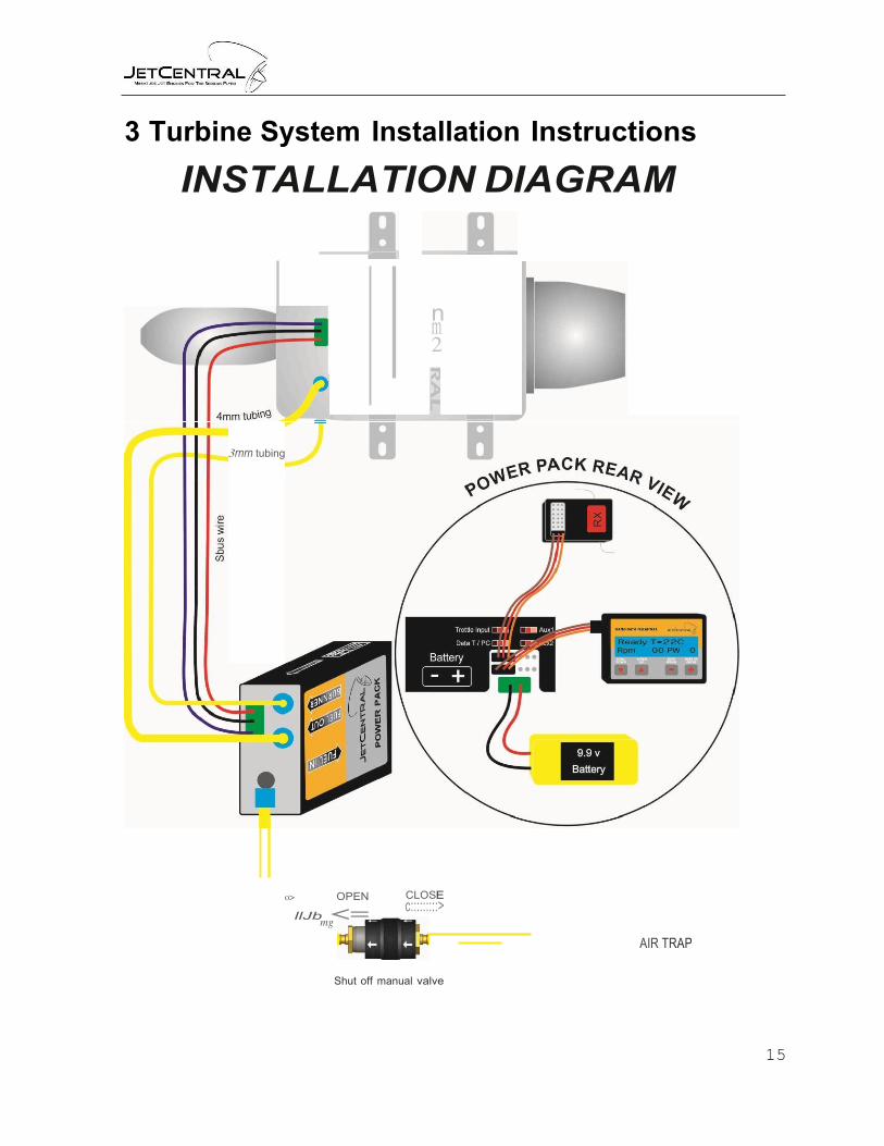
3 Turbine System Installation Instructions
INSTALLATION DIAGRAM
n m 2
3rnrn tubing
o> OPEN
llJb mg
CLOSE c:::::::::>
AIR TRAP
Shut off manual valve

16
3.1 POWERPACK / ECU
Connections:
· Throttle input to the receiver: JR type servo cable (Throttle RX) · Multiplex Battery input · S-BUS Multiplex connector · Hand Data Terminal / PC interface · 6mm Fuel line inlet · 4mm Fuel Line Outlet · 3mm Burner Fuel Outlet
Note: In all power cables the black is the common and negative. This means that all the black cables are connected internally together and to the negative of the pump/starter battery.
Connect the cables to their assigned places, Note that some of the JR type connectors used can be connected in the wrong location or inverted.
Use the colored labels on the POWERPACK / ECU body to connect the connectors in to their assigned place. The input / output connectors have been designed to prevent damage to the internal circuitry in the case of an incorrect connection.
IMPORTANT! Use only 5 cell 6V packs on your receiver; this will insure proper operation of the POWERPACK / ECU electronics. You can use a regulator if wished but we find 6V packs work just fine with today's radio equipment. Tests have shown that turbine electronics may be affected from glitches by using lower 4.8 Volt packs powering the radio system.
· Use the recommended (supplied) starter motor battery type, the two supported
battery types are LiPo 2s or A123 3s.
17
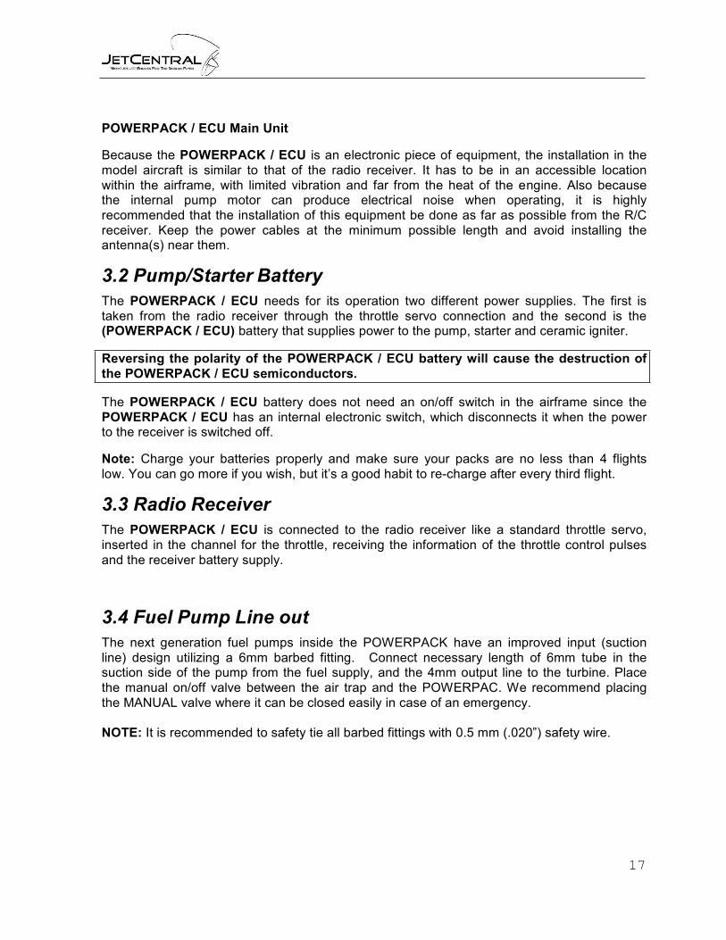
POWERPACK / ECU Main Unit
Because the POWERPACK / ECU is an electronic piece of equipment, the installation in the model aircraft is similar to that of the radio receiver. It has to be in an accessible location within the airframe, with limited vibration and far from the heat of the engine. Also because the internal pump motor can produce electrical noise when operating, it is highly recommended that the installation of this equipment be done as far as possible from the R/C receiver. Keep the power cables at the minimum possible length and avoid installing the antenna(s) near them.
3.2 Pump/Starter Battery
The POWERPACK / ECU needs for its operation two different power supplies. The first is taken from the radio receiver through the throttle servo connection and the second is the (POWERPACK / ECU) battery that supplies power to the pump, starter and ceramic igniter.
Reversing the polarity of the POWERPACK / ECU battery will cause the destruction of the POWERPACK / ECU semiconductors.
The POWERPACK / ECU battery does not need an on/off switch in the airframe since the POWERPACK / ECU has an internal electronic switch, which disconnects it when the power to the receiver is switched off.
Note: Charge your batteries properly and make sure your packs are no less than 4 flights low. You can go more if you wish, but it’s a good habit to re-charge after every third flight.
3.3 Radio Receiver
The POWERPACK / ECU is connected to the radio receiver like a standard throttle servo, inserted in the channel for the throttle, receiving the information of the throttle control pulses and the receiver battery supply.
3.4 Fuel Pump Line out
The next generation fuel pumps inside the POWERPACK have an improved input (suction line) design utilizing a 6mm barbed fitting. Connect necessary length of 6mm tube in the suction side of the pump from the fuel supply, and the 4mm output line to the turbine. Place the manual on/off valve between the air trap and the POWERPAC. We recommend placing the MANUAL valve where it can be closed easily in case of an emergency.
NOTE: It is recommended to safety tie all barbed fittings with 0.5 mm (.020”) safety wire.

18
3 mm pressure to turbine burner 4 mm pressure to turbine main fuel line
6 mm Suction / to fuel tank
4 Programming the POWERPACK / ECU
The HDT has a LCD with 16 characters, 2 rows and four buttons which allow you to move through the various menus and to change the data settings in each menu page. The presentation of data has been organized in screens. The first two, displays the engine status readings in real time and the following screens allow you to modify the operating parameters. All of the parameters can be modified while the engine is running, so it is easy to tune the engine without having to start it again to test the new settings. Both left buttons allow you to move through the different screens in an ascending mode (Menu Up) or descending mode (Menu Down). Both right buttons allow you to change the data in increasing value (Up Data) or decreasing value (Down Data).
Menu down Data up/Enter
Menu up Data down

19
4.1 First Screen
When you have connected the POWERPACK / ECU and you turn on the RX, appears briefly the presentation screen with the brand and model engine.
4.2 Main Screen
This screen displays the status of the turbine temperature (in degrees Centigrade), RPM and the power supplied to the fuel pump (PW). This goes from 0 to 999. Note: Numbers exceeding PW values of 600 may indicate restritctions in the fuel system or a faulty fuel pump.
4.3 Secondary Screen
When the Menu Up button is selected the secondary screen is displayed.
Displayed are the pulse width from your transmitter, the % of the accelerator (throttle) stick, below is the voltage of the POWERPACK / ECU battery and it’s consumption in amps.
4.4 Menu Screen
By pressing the Menu Up button the menu screen will be displayed.
Displayed are the fourmenus to choose from:
Start
Info
Radio
Run
To acess each menu, simply push the corresponding button.
Start – menu down ( )
Info – menu up ( )
Radio – data down ( - )
Run – data up ( + )

20
All the parameters in the submenus are factory preadjusted and are a good starting point to fine tunning your engine. Note: Only make small changes at one time when adjusting the turbine parameters.
4.5 Start Submenu.
When selecting the “Start” submenu the Startup Parameters screen is displayed.
The next screen is activated by pressing the “menu up” button will display “Pump Pw. Ignt. K”. Entries are numeric values between 000 and 255
This is the only fuel adjustment you have in Kerostart mode but it is most critical. A value that is too low will probably get the fuel ignited but it will not raise the temperature enough to trigger the preheat mode, so if you hear or see flames inside the turbine but you
still get “Ignition fail” alarm, increase this value one point at a time until it creates a sufficient temperature change to pass to next step.
When selecting the menu up button the “Glow plug power” screen is displayed.
With the Data up and Data down buttons you can change this value. The value is programmed as a voltage. The idea is to have the lowest possible value that will ignite the gas to conserve battery power. Default value is 5.5V; values can be changed in 0.1 volt increments.
Next is the “Low Batt. Volts”, this is minimum voltage that the battery can drop during the start up without trigging the “Low Battery” alarm, If it’s adjusted too low it can provoke hot or failed starts, too high and it will only allow a couple of start ups

21
4.6 Info Submenu
When this option is selected, the first screen will show the first avaliable timer.
“Timer service:” – The total time in minutes that your turbine has run since last service
“Last:”- The time in seconds of your last run
“Cy:” – The number of cycles (start, run, off) your turbine has
The next screen lists dropped pulses, the total time duration of the lost signal and the RX voltage
In the next screen is the “Tot. Time:” this timer is the total run time of your turbine since it was manufactured
Below is the turbine serial number and the software version
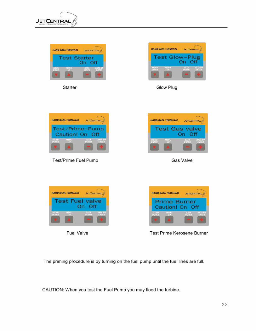
The next six options are test options. For access to these options you must have the trim down on your transmitter. They all have an ON (-) / OFF (+) button and you can test them individually: the Starter, Glow Plug, Fuel Pump, Gas Valve and Fuel Valve.
22
Starter Glow Plug
Test/Prime Fuel Pump Gas Valve
Fuel Valve Test Prime Kerosene Burner
The priming procedure is by turning on the fuel pump until the fuel lines are full.
CAUTION: When you test the Fuel Pump you may flood the turbine.
23
4.7 Radio Submenu IMPORTANT – Please Read
Before programming the POWERPACK / ECU to learn your transmitter throttle settings, it is important that you clear your transmitter of all and any MIX or FAILSAFE program you might have programmed connected to the throttle channel, since this can interfere with the operation of the POWERPACK / ECU
Program your failsafe after you have programmed the POWERPACK / ECU to learn your transmitter throttle settings.
Here are some key items not to forget to check:
· Your transmitters throttle channel ATV, end points or travel adjustments should be at
100% with no reductions or mixes to it
· When your trim is down, HDT should read “Trim Low” and 0%
· When trim is up, HDT should read “Ready” and about 25%
· When you raise throttle to maximum, HDT should read 100%
· Always program your failsafe after you program your POWERPACK / ECU and set it to “ENGINE CUT” Throttle down and Trim Down
· Check that your failsafe is working properly
4.8 Transmitter Setup
4.8.1 Transmitter Preparation and Verification.
First unplug the fuel pump/starter battery to prevent accidental starting of the engine.
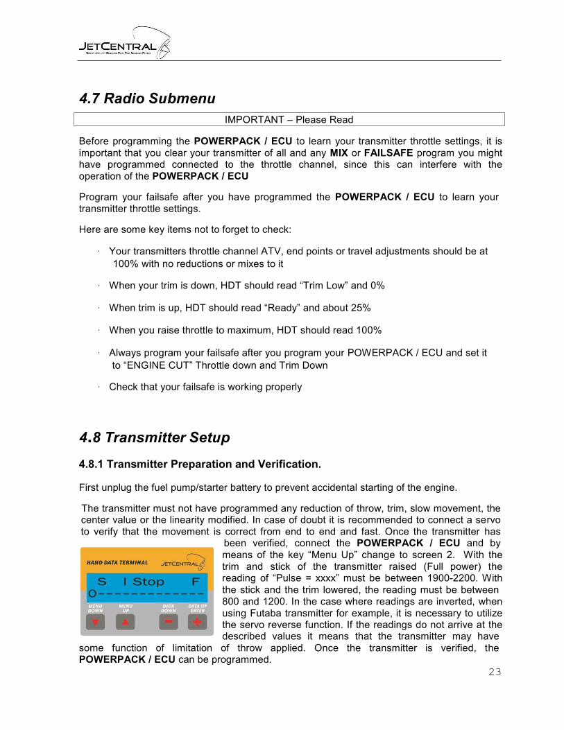
The transmitter must not have programmed any reduction of throw, trim, slow movement, the center value or the linearity modified. In case of doubt it is recommended to connect a servo to verify that the movement is correct from end to end and fast. Once the transmitter has
been verified, connect the POWERPACK / ECU and by means of the key “Menu Up” change to screen 2. With the trim and stick of the transmitter raised (Full power) the reading of “Pulse = xxxx” must be between 1900-2200. With the stick and the trim lowered, the reading must be between 800 and 1200. In the case where readings are inverted, when using Futaba transmitter for example, it is necessary to utilize the servo reverse function. If the readings do not arrive at the described values it means that the transmitter may have
some function of limitation of throw applied. Once the transmitter is verified, the POWERPACK / ECU can be programmed.

24
To program the throttle stick position select the menu screen, and then press the “radio” submenu to get to the adjust screen.
This first menu is only informative and it warns you of the entrance into the screens of programming of the throttle control. Press the button 'Data Up' to enter in the programming menus. Next the screen of programming the full throttle position is displayed.
In order to program these parameters locate the trim and stick in the maximum position. Once located in this position, push the button "Data Up". At this moment the POWERPACK / ECU will record this as the position of full power.
The following screen allows programming the lower limit (Stop). In order to do this, locate the trim and stick to the minimum position and push the button "Data Up”.
The last screen is the position of the trim that will correspond to the idle of the turbine. To make this adjustment locate the stick to the minimum position and the trim to the maximum position then push the button “Data Up”.
Note: When in the transmitter adjustment menu and changes to transmitter adjustment are not required pushing the “Menu up” button will cause the screen to change without varying the previous adjustment.
Once the programming of the transmitter is finished it can be verified by means of the secondary screen of the HDT.
25
To the right of the value of the transmitter’s received pulse width values are displayed from 0 to 100%. This value must correspond to the relative position of the throttle stick, matching 0% to the lowest stick and trim position and, 100% to the stick and trim maximum position. If these values were not reached, or the limits of the 0 or 100% were reached before pushing the stick to the end of its travel, the calibration process must be repeated.
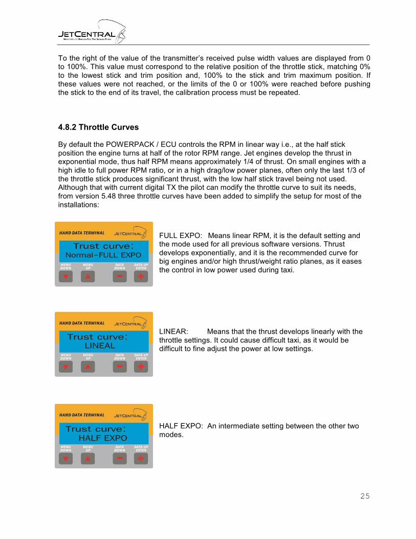
4.8.2 Throttle Curves
By default the POWERPACK / ECU controls the RPM in linear way i.e., at the half stick position the engine turns at half of the rotor RPM range. Jet engines develop the thrust in exponential mode, thus half RPM means approximately 1/4 of thrust. On small engines with a high idle to full power RPM ratio, or in a high drag/low power planes, often only the last 1/3 of the throttle stick produces significant thrust, with the low half stick travel being not used. Although that with current digital TX the pilot can modify the throttle curve to suit its needs, from version 5.48 three throttle curves have been added to simplify the setup for most of the installations:
FULL EXPO: Means linear RPM, it is the default setting and the mode used for all previous software versions. Thrust develops exponentially, and it is the recommended curve for big engines and/or high thrust/weight ratio planes, as it eases the control in low power used during taxi.
LINEAR: Means that the thrust develops linearly with the throttle settings. It could cause difficult taxi, as it would be difficult to fine adjust the power at low settings.
HALF EXPO: An intermediate setting between the other two modes.

26
STICK POSITION
MODE 0% (idle) 25% 50% 75% 100%
FULL EXPO Idle thrust 6% 25% 56% 100%
% of total thrust HALF EXPO Idle thrust 16% 38% 66% 100%
LINEAR Idle thrust 25% 50% 75% 100%
4.9 Run Submenu
When you select this option you will enter the normal run parameter.
With menu up you get in the “Full power speed”
The maximum RPM limit is set to get the desired thrust accordingnto the attached chart. The Factory set default value is 152,000 RPM
With menu up you get in the “Idle speed”
The idle RPM is set with this value, default value is 42,000 RPM

27
Thru
st in
Lb
R.P.M. / Thrust
Rabbit 100
22,00
20,00
18,00
16,00
14,00
12,00
10,00
8,00
6,00
4,00
2,00
0,00
40 48 56 64 72 80 88 96 104 112 120 128 136 144 152
RPM
4.10 Last Run Reason
Last power-down cause
The POWERPACK / ECU stores in its internal memory the measurements taken from the turbine for each 0.5s up to 52 minutes. These measurements are RPM, temperature, throttle position and pump power. This data can only be downloaded through a PC and a RS232 cable, but the user can check through the HDT the cause of the last power down and the measures of the engine at the moment when the POWERPACK / ECU cut the engine. This feature is useful to track the cause of a flame out in flight. After power up, set the trim low and press the “Menu Down” button. The HDT will show the cause of the last shut down, and the EGT, RPM and pump power at this moment during 2 sec.
28
User Off – Means that was shutdown from the transmiter by a trim down or throtle cut
Low RPM – Means that the POWERPACK / ECU registered a lower RPM than the
minimum factory programmed value
Hi Temp – Means that the POWERPACK / ECU registered a temperature higher than the maximum factory programmed value
Fail Safe – Means that the pulse with from the RX was out of the programed values
All this data is very important to determinate the cause of the last shutdown or flame out.
In case this information is not enough to determinate the causes, the POWERPACK / ECU stores the last 51 minutes of use, and can be downloaded to a computer through the optional data link.
Please contact your dealer for advise.
5 Radio Link Failsafe
In the case that the receiver has a radio link failure, it will output the failsafe settings. The POWERPACK / ECU will set the power at idle during 1 second after receiving the stop command, and if during this time the receiver exits from failsafe the engine will go back to the throttle set power. If not, it will be cut-off. This system allows flying through small glitches while retaining the ability to kill the engine in the case of radio failure.
ALWAYS PROGRAM THE FAILSAFE TO KILL THE ENGINE. NEVER FLY A TURBINE PLANE WITH THE FAILSAFE SET TO “HOLD”.
5.1 PPM systems
In the case of radio failure (erratic movement of the servos or pulses out of the programmed values window), the POWERPACK / ECU sets the power to idle during approximately 1 sec. If the radio link is regained in this time, the power goes back to normal, if not; the system will kill the engine.
5.2 2.4 systems
Adjust the failsafe position of throttle channel to -125%
If your transmitter system does not allow you to program it this way, program it to “STOP” position

29
Testing and verifying the failsafe, verification can be performed either by starting the turbine or using the HDT display.
Verification by Starting the Turbine
1. Start the engine. Set the power to any setting above idle.
2. Turn off the transmitter but leave the receiver on and engine running.
Verify that the engine power goes to idle after 0.5s and shutdown after 2 s. If signal from Tx is re-gained during these 2s, power will return to normal.
Note: this is only valid when using non 2.4 GHz equipment, with 2.4 GHz equipment the Turbine will shut down immediately with the powering down of the transmitter, the reboot time of the power up sequence is longer than two seconds therefore signal cannot be regained in the time allotted.
6 Starting the engine
6.2.1 Preparing the turbine for running
Always test the turbine on a test bench before installing it into the plane, this will confirm that all systems work as they should, and you will be able to learn its operation and the emergency procedures. A suitable platform/table/workbench is required to clamp the test stand onto. Make sure this can be easily transported outside and weighs enough to ensure it cannot be blown over by the thrust of the engine.
Select a clear area for running – keep clear of areas with loose leaves, sand or other debris that could be picked up or drawn towards the intake. Ensure the fuel tank is position well clear of the exhaust area and is secured.
6.2.2 Important notes for kerostart turbines
The kerostart system used on all Jet Central turbines is reliable and well tested system that produces very smooth and trouble free starts. However, extra care and attention must be paid when starting a kerostart turbine.
The main difference between gas and kerosene starting is that in the case of a failed ignition, with gas starting the gas dissipates quickly in the air and isn’t kept inside the engine Kerosene is liquid and, if unburned, will pool inside the engine and stay there. The engine can hold a large quantity of kerosene inside. This kerosene will be ignited on next successful start up and will be pushed to the exhaust as soon as the airflow inside the engine is sufficient, and will be ignited in the exhaust, causing a hot start (in extreme cases a big fireball) that will not hurt the turbine, but can destroy the model.

30
To prevent this:
· During the start-up listen to the turbine sound to check for positive sound of ignition, check looking from the exhaust that the kero is burning, or check for an increase in exhaust temperature in the data terminal.
If you see a small plume of white smoke from the exhaust mean that the kero is not burning, so the kero is pooling inside the engine. Abort the start immediately.
· After a failed start, or whatever condition could cause that fuel be collected inside the engine (i.e. extra priming), ALWAYS empty the engine of fuel by tilting the engine nose down. Fuel will exit through the intake. Do not tilt upwards, due at the internal engine construction; the fuel cannot exit through exhaust.
Another big difference between gas start and kero start is that the kerosene can keep burning during long time inside the engine. This situation usually happens during an aborted start. The start-up sequence is aborted by the user or automatically before the engine arrives to idle. This can cause that the kerosene inside the engine to keep burning for long time, and could destroy the engine or the model. IF A STARTUP SEQUENCE IS NOT COMPLETED, ALWAYS CHECK FOR FLAME INSIDE THE ENGINE. If there is flame, lower the trim and then set full throttle to engage the starter and blow out the flame, it takes a couple of seconds to engage. USE SHORT BURSTS OF STARTER. Using the starter for long time can destroy the starter motor. In the case that the start-up procedure has been aborted due at starter failure, then it will be necessary to apply the CO2 fire extinguisher. White smoke from the engine is a good indication here; mean that there is no fire inside.
6.2.3 First engine runs
· Confirm your test stand is securely fixed to a bench or heavy table. Keep your ear defenders within easy reach and a CO2 fire extinguisher handy. THIS IS VERY IMPORTANT ON KEROSTART ENGINES.
· Fill the fuel tank. Do not forget to filter the fuel, and to mix the oil. · Confirm all batteries are freshly charged and connected up. USE ONLY 7.4V
Batteries. · Check there is a temperature reading on the data terminal. · Ensure the running area is clear of onlookers – especially the prohibited zone of a 10
meter radius 180° arc from engine center around the rear. · Verify that the fuel tubes are full of fuel and purged of all air, if not; carry out the fuel
prime sequence as described here.
6.2.4. Priming the fuel system
Both main fuel and starting fuel lines require the purging of all air after initial installation. Take extra care when priming the lines; ensure that excess fuel is not pumped into the turbine.

31
A special menu on the POWERPACK / ECU facilitates priming. Set the trim to low and go to “Info” menus and next to “Pump test”. Click on “on” / ”off” to start/stop the pump manually. Please observe fuel line to engine very carefully and push the off button to shutoff as soon as fuel reaches engine. Repeat the same operation on the burner line by the appropriate menu entry (Prime Burner), except that after stopping the fuel when it reaches the turbine case restart the prime for and additional three seconds to get the start fuel down to the igniter’ If this step is not completed a series of “start bad” errors may occur until the fuel reaches the igniter.
IMPORTANT:
The prime procedure should be done only to fill the fuel tubes and filters in the case of a first installation or in case of disassembling of the tubes. Do not run the prime function so that the engine becomes flooded by fuel, as this will cause an uncontrolled fire (Hot Start) at next startup.
6.2.5 Starting the engine
Set the throttle stick down and the trim up. “Idle” - Confirm that the screen shows “Ready” - Ready to start!
Move the stick to full throttle and then back to idle again. The POWERPACK / ECU will begin the startup sequence as described below:
First the internal ceramic igniter will be energized and after 6-10 seconds, depending on the engine temperature and battery charge, the starter will be powered up to have the rotor turning at 3000 RPM.
Once the rotor is at speed, the internal pump and solenoid valves will be energized in pulsating mode A few seconds later the kerosene will ignite and the exhaust temperature will begin to increase. The rpm and pump power will increase automatically. During this phase the data terminal will display “STAR ON”.
When the exhaust temperature has increased enough, the data terminal reading will change to “SWITCHOVER”, during this phase the fuel will be routed to main injectors and the speed of the rotor will be progressively increased to 12,000 RPM.

32
Once this phase is finished, the reading will be “FUEL RAMP”. In this phase the engine receives fuel only through its normal fuel input, and battery power to the internal ceramic igniter will be disconnected. The fuel flow and starter power will be increased automatically to increase the RPM up to idle RPM. When 25.000 RPM is reached the POWERPACK / ECU will automatically disconnect power to the starter.
When the rotor speed reaches idle, the screen will change to “running” and the engine speed is stabilized.
The engine is running!
Control of engine power/rpm is now handed back to the transmitter and controlled by the position of the throttle stick.
Increase/decrease the throttle slowly, verifying that the engine accelerates/decelerates. Leave at full throttle to verify that turbine has reached max RPM, if not the “CALC PUMP” screen will appear, meaning that the ECU is changing and memorizing new conditions. Leave it there until it changes back to “RUNNING”
Take special care around the engine intake; keep your hands at a safe distance along with any other objects as they can be easily ingested.
6.2.6 Engine shut down procedure
To shut down the engine lower the trim and the stick. Is recommendable that before shutting down the engine please restrain the model then raise the throttle stick to approximately 25%, allowing temperatures to stabilize for around 5 seconds before carrying out the shutdown procedure.
Note: Trim must be in the lowest position in order for the Auto Cool down to work. At this moment you can turn Off the RX and transmitter and the turbine will continue the cool down sequence until the temperature gets below 100º, then it will turn itself off
WHAT TO DO IN THE CASE OF AN EMERGENCY
During the start sequence the POWERPACK / ECU will be in charge of everything, controlling temperature and RPM. The only thing the user can do is to abort the sequence by lowering the trim in the case that something abnormal (excessive flames in the exhaust, etc).
If a problem is detected, first:
MOVE THE TRIM TO THE LOW POSITION TO ABORT THE SEQUENCE.

33
If there is a fire in the engine and the problem is because the starter has failed or the engine is seized (not turning),
IMMEDIATELY APPLY THE FIRE EXTINGUISHER through the intake side of the engine, never trough the exhaust.
If there is a fire, but the rotor remains free to spin and the starter is OK, raise the trim and stick to the full power position this will connect the starter manually to ventilate the engine and extinguish the fire. The throttle channel acts as a starter switch if the temperature is over 100ºC after an aborted start.
USE SHORT BURSTS OF STARTER. Using the starter for long time can destroy the starter motor.
6.3 List of POWERPACK / ECU message codes
Here is a list of possible messages shown on the data terminal screen and their meaning.
Message Means Trim Low Indicates that the signal received from the transmitter corresponds to the
lowered trim, that is to say, engine OFF. Ready Indicates that the engine is ready for starting, and that the transmitter signal
corresponds to IDLE, (Blue LED lit). Stick Low This indicates that the throttle stick is in a position above IDLE, the engine will
not start with the stick in this position, so the stick must set Low. Glow Test Verification of igniter and preheat cycle. Start On Test of the starter. Ignition Kerosene ignition phase and heating of the combustion chamber. Switchover Phase of switching the kerosene feed from igniter to normal injectors. Fuel Ramp Phase of acceleration until idle speed is reached Running Engine working correctly, full control of turbine power reverted back to
transmitter. Stop Turbine off. Cooling The starter is operating to cool the engine. Glow Bad Defective or disconnected igniter Start Bad Defective starter, insufficient RPM reached during start. Low RPM Engine speed below the minimum. High Temp Excessive temperature. IGN. Fail Battery No Engine Data
Insufficient Temper rise for the preset time duration Battery voltage out of limits Data bus cable disconnected from de engine

34
7 Fuel and Fuel System Care
Your JET CENTRAL micro turbine can burn deodorized kerosene-k, kerosene Jet-A or Diesel for fuel; the fuel must be mixed with oil as follows:
Jet Central recommends using 2 strokes 100% synthetic oil mixed in 2% (50-1) to 2.5% (40- 1) ratios. Any recognized brand that meets the norm “JASO FC” will work. Another alternative is 100% synthetic turbine oil mixed in ratios from 2.5% (40-1) to 5% (20-1); however this type of oil is not recommended from a health and safety aspect because it’s been proven to be toxic. The last alternative is Mobil DTE light in with a mixing ratio of 5% (20-1).
You may use an additional onboard filter beyond what is shown in the diagrams if you wish. We use an automotive type filter and filter the fuel before it goes into the tank.
Header Tank
Jet Central recommends a header tank with some type of bubble eliminator or an Orbit clunk. This is a requirement if you want to take every possible measure to insure against flame outs.
Fuel Line
Jet Central recommends to safety tie all barbed fittings with 0.5 mm (.020”) safety wire. Unless they are a Festo type of connection.
Tanks
Always use a gasoline compatible stopper; as for fuel tanks, Dubro style and Kevlar tanks work fine and seem to have the best impact resistance; but always use a 5/32 size brass tubing for pick up and vents, this ensures your fuel flow is always flowing without resistance.
35
8 Multiengine Installation
For multiengine installation, first set up each turbine as per manual, start and run each engine separately. Then, when the Turbines are starting and running smooth, plug the throttle leads from each of the POWERPACK / ECU’s into a “Y” connector and plug the central lead into your throttle channel. Now both turbines will start at the same time and shut down at the same time. This is preferred over individual starting and is a simple way of assuring you’re taking off on both turbines!
Helpful Tips
· If one turbine starts and the other doesn’t for any reason, just cycle the throttle again;
the one not running will enter the re-start sequence.
· In multiengine installations always have each turbine with its own complete fuel system.
· As the POWERPACK / ECU has auto restart feature, if it is required to shut down after
the turbines are running and need to restart quickly, just raise the trim to the ready position and cycle the throttle, when the auto cool down cycle gets the turbine to a safe temperature the POWERPACK / ECU will restart the turbines automatically.
· Place on/off switches on the throttle lead before the “Y” connector that plugs the
POWERPACK / ECU’s throttle channel into the receiver, this way you can shut off one turbine or the other on the ground or start one at a time by turning off the engine desired, it is also helpful if you have a “BAD START” on one turbine to reset the POWERPACK / ECU.
36
9 Maintenance
Due to being an advanced design over other popular turbines you will find that your JET CENTRAL turbine needs less maintenance and your turbine will only need to be properly cared for to get hours of enjoyment. We have new state of the art bearing systems, precision made combustion chambers and high efficiency turbine wheels that take heat and load of the main components thus greatly extending service requirements. If you find yourself needing service just call! We have a special system in place to give you quick turn around and for all major repairs your JET CENTRAL Turbine goes back to its ISO 9000 factory, were it was built to be repaired; this ensures a quick turn around with quality workmanship and keeps major repairs to the least cost.
Warranty - in order to maintain the lifetime warranty the turbine must be returned to the factory for inspection and service at 25 hour intervals, the cost of this service is published on the Jet Central web site.
37
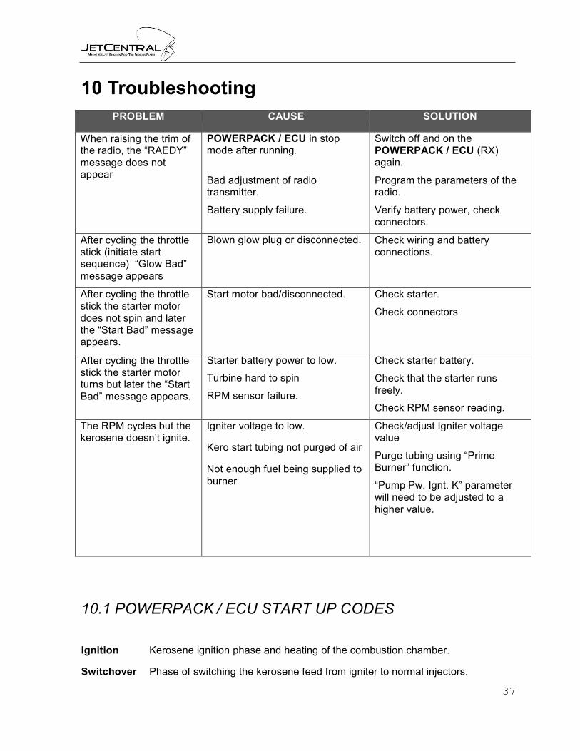
10 Troubleshooting
PROBLEM CAUSE SOLUTION
When raising the trim of the radio, the “RAEDY” message does not appear
POWERPACK / ECU in stop mode after running.
Bad adjustment of radio transmitter.
Battery supply failure.
Switch off and on the POWERPACK / ECU (RX) again.
Program the parameters of the radio.
Verify battery power, check connectors.
After cycling the throttle stick (initiate start sequence) “Glow Bad” message appears
Blown glow plug or disconnected. Check wiring and battery connections.
After cycling the throttle stick the starter motor does not spin and later the “Start Bad” message appears.
Start motor bad/disconnected. Check starter.
Check connectors
After cycling the throttle stick the starter motor turns but later the “Start Bad” message appears.
Starter battery power to low.
Turbine hard to spin
RPM sensor failure.
Check starter battery.
Check that the starter runs freely.
Check RPM sensor reading.
The RPM cycles but the kerosene doesn’t ignite.
Igniter voltage to low. Kero start tubing not purged of air
Not enough fuel being supplied to burner
Check/adjust Igniter voltage value
Purge tubing using “Prime Burner” function.
“Pump Pw. Ignt. K” parameter will need to be adjusted to a higher value.
10.1 POWERPACK / ECU START UP CODES
Ignition Kerosene ignition phase and heating of the combustion chamber.
Switchover Phase of switching the kerosene feed from igniter to normal injectors.

38
Fuel Ramp Phase of acceleration until idle speed
Running Engine working correctly, pilot have full control of engine power.
Stop Engine off.
Flame out Exhaust GAS Temperature below the minimum.
IGN. Fail Insufficient Temper rise for the preset time duration
10.2 POWERPACK / ECU SHUTDOWN CODES
The POWERPACK / ECU will always display the reason for the last shut down. It will also display the error code and the engine parameters. The following are the error codes and what they infer. It is important that in the event of an unwanted shut down that the given parameters and codes are noted to determine what has happened before restarting the turbine. The error codes will be reset upon the next successful start of the turbine.
USER OFF The POWERPACK / ECU has received the shutdown command from the receiver
RX PWR The POWERPACK / ECU lost power from the receiver
FAILSAFE The POWERPACK / ECU received the failsafe command from the receiver
FLAME OUT The POWERPACK / ECU lost the temperature reading from the thermocouple
SPEEDLOW The POWERPACK / ECU has shut the turbine down due to the fact the RPM has fallen below a certain RPM
AUTOMODE The POWERPACK / ECU has received a start command after initiated an auto start
IMPORTANT PARAMETERS - In each of the above codes also these important parameters will be displayed:
· TEMPERATURE
· RPM
· PUMP POWER
The POWERPACK / ECU stores at last 10 min run time parameters to help in diagnosing any issues.
39
11 Safety Tips
• Remember to always have a fire extinguisher present during operations
• Caution a flooded turbine will lead to a hot start
• Inspect all turbine fuel connections and wiring periodically
• Safety wire all fuel connections
• Follow all instructions contained in this manual; learn all operations of the POWERPACK / ECU
• Under no circumstances charge your LiPo battery while installed in your aircraft
• Never operate the turbine indoors
Enjoy your new Jet Central Turbine. Your Jet Central Team welcomes you aboard and thanks you for selecting our product for your new turbine.

40
12 Worldwide Service
USA Jet Central Eric Clapp 7162 Dogwood Court North Port, Florida 34287 Office: 941-468-1246 Home: 941-423-9931 www.jetcentralusa.com [email protected]
Germany
RESCUE - Turbinen-Service (service only) Uwe KannapinCordinger Str. 98 D – 29699 Bomlitz www.ukpraezitec.de [email protected]
Spain
Asoc. Cast.de Aeromodelismo Turbin (Only Field Assistance) Ramón Lozano Yuste Av. del Puerto No. 252 Grao de Castellón, 12100 Tel. (34) 964 281331
México
Factory Direct Juan Ramón Ruiz Coltongo 158 02630 México D.F. Tel. + (55) 5090 7477 www.jetcentral.com.mx [email protected]
Please take note of different time zones, as JET CENTRAL is a worldwide company.

41
Appendix A: Rabbit Mounting Dimensions 1
-J
[o@
/) /
"""
[ @ @ ;-•J t
r
@) _] "-"'J
'- i
, '1f0 ,
1 This drawing is not fit to scale. Please check the website for a PDF that prints at scale.
0 ©
0 ©
'-
© Q_
© Q_
g:
· -
( wJ
0 "<;f"
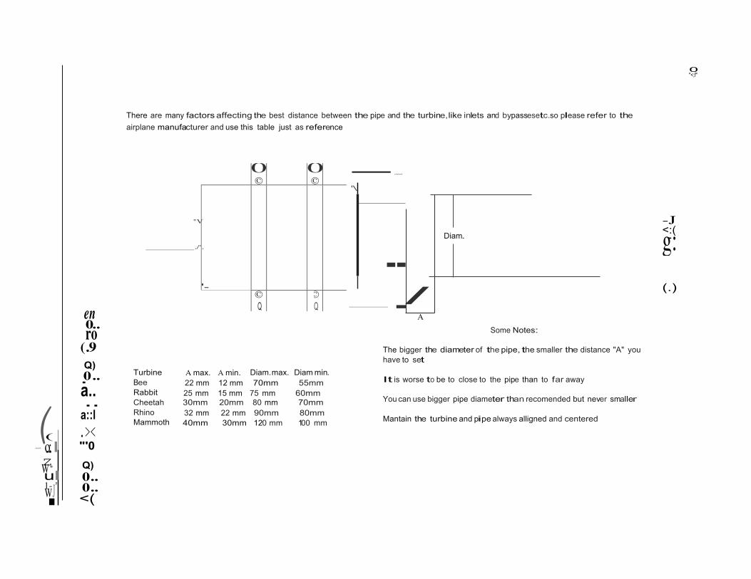
There are many factors affecting the best distance between the pipe and the turbine,like inlets and bypassesetc.so please refer to the airplane manufacturer and use this table just as reference
.......
'\
"V
./'.
Diam.
-- /
-J <:( (.)
en 0ro..
- A Some Notes:
(.9 Q) 0.. a..
Turbine Bee Rabbit
A max. A min. 22 mm 12 mm 25 mm 15 mm
Diam.max. 70mm
75 mm
Diam min. 55mm
60mm
The bigger the diameter of the pipe, the smaller the distance "A" you have to set It is worse to be to close to the pipe than to far away
.. a::l
Cheetah Rhino Mammoth
30mm 32 mm 40mm
20mm 22 mm 30mm
80 mm 90mm 120 mm
70mm 80mm 100 mm
You can use bigger pipe diameter than recomended but never smaller Mantain the turbine and pipe always alligned and centered
( .>< --- o--:I "'0 zw· Q) ul 0.. 1- ' 0.. I <(