Embed Size (px)
Citation preview
Copyright American Petroleum Institute Provided by IHS under license with API No reproduction or networking permitted
--``,`,`,``,,`,```,,,```,,`,`,`,-`-`,,`,,`,`,,`---
Operation and Maintenance of Offshore Cranes
API RECOMMENDED PRACTICE 2DSIXTH EDITION, MAY 2007
Licensee=ExxonMobil/1890500101, User=Baldwin, ClydeNot for Resale, 02/16/2011 06:46:38 MST without license from IHS

Copyright American Petroleum Institute Provided by IHS under license with API Licensee=ExxonMobil/1890500101, User=Baldwin, Clyde
Not for Resale, 02/16/2011 06:46:38 MSTNo reproduction or networking permitted without license from IHS
--``,`,`,``,,`,```,,,```,,`,`,`,-`-`,,`,,`,`,,`---
Copyright American Petroleum Institute Provided by IHS under license with API No reproduction or networking permitted
Operation and Maintenance of Offshore Cranes
Upstream Segment
API RECOMMENDED PRACTICE 2D SIXTH EDITION, MAY 2007
Licensee=ExxonMobil/1890500101, User=Baldwin, ClydeNot for Resale, 02/16/2011 06:46:38 MST without license from IHS
--``,`,`,``,,`,```,,,```,,`,`,`,-`-`,,`,,`,`,,`---

Copyright American Petroleum Institute Provided by IHS under license with API Licensee=ExxonMobil/1890500101, User=Baldwin, Clyde
Not for Resale, 02/16/2011 06:46:38 MSTNo reproduction or networking permitted without license from IHS
--``,`,`,``,,`,```,,,```,,`,`,`,-`-`,,`,,`,`,,`---
SPECIAL NOTES
API publications necessarily address problems of a general nature. With respect to particular circumstances, local, state, and federal laws and regulations should be reviewed.
Neither API nor any of API’s employees, subcontractors, consultants, committees, or other assignees make any warranty or representation, either express or implied, with respect to the accuracy, completeness, or usefulness of the information contained herein, or assume any liability or responsibility for any use, or the results of such use, of any information or process disclosed in this publication. Neither API nor any of API’s employees, subcontractors, con-sultants, or other assignees represent that use of this publication would not infringe upon pri-vately owned rights.
API publications may be used by anyone desiring to do so. Every effort has been made by the Institute to assure the accuracy and reliability of the data contained in them; however, the Institute makes no representation, warranty, or guarantee in connection with this publication and hereby expressly disclaims any liability or responsibility for loss or damage resulting from its use or for the violation of any authorities having jurisdiction with which this publi-cation may conflict.
API publications are published to facilitate the broad availability of proven, sound engineer-ing and operating practices. These publications are not intended to obviate the need for applying sound engineering judgment regarding when and where these publications should be utilized. The formulation and publication of API publications is not intended in any way to inhibit anyone from using any other practices.
Any manufacturer marking equipment or materials in conformance with the marking requirements of an API standard is solely responsible for complying with all the applicable requirements of that standard. API does not represent, warrant, or guarantee that such prod-ucts do in fact conform to the applicable API standard.
All rights reserved. No part of this work may be reproduced, stored in a retrieval system, or transmitted by any means, electronic, mechanical, photocopying, recording, or otherwise,
without prior written permission from the publisher. Contact the Publisher, API Publishing Services, 1220 L Street, N.W., Washington, D.C. 20005.
Copyright © 2007 American Petroleum Institute
Copyright American Petroleum Institute Provided by IHS under license with API Licensee=ExxonMobil/1890500101, User=Baldwin, Clyde
Not for Resale, 02/16/2011 06:46:38 MSTNo reproduction or networking permitted without license from IHS
--``,`,`,``,,`,```,,,```,,`,`,`,-`-`,,`,,`,`,,`---
Copyright American Petroleum Institute Provided by IHS under license with API No reproduction or networking permitted w
FOREWORD
This Recommended Practice is under the jurisdiction of the API Executive Committee on Drilling and Production Operations and was developed in cooperation with the Offshore Operators Committee. Detailed requirements for the design and construction of offshore cranes are given in API Specification 2C Specification for Offshore Cranes (latest edition).
Guidelines provided herein on the operation, inspection and maintenance of offshore cranes are based in part on an understanding of the cranes’ design and construction. Therefore, this document should be read in conjunction with API Spec 2C.
The material in this publication represents the contribution of industry representatives of crane users, crane manufacturers, wire rope manufacturers and ancillary crane device or component manufacturers. It is based on industry experience and expertise involving world-wide operations.
This publication is organized into text sections and associated supporting appendices. In the Text Sections, practices and procedures considered to be mandatory; standards and qualifica-tions that are deemed necessary minimum; and the overall intent, goals and objectives of crane operating, inspection and maintenance practices, programs and procedures, are defined.
In the appendices, the basis for the recommended mandatory practices, minimum standards and program goals, are substantiated; non-mandatory practices are discussed and illustrated; and examples of programs, which meet the intent of the guidelines, are given.
It should be understood that the crane operating and maintenance practices recommended herein by necessity collectively cover a wide range of crane types and configurations. Not all practices are applicable to all cranes. When applying this RP, care should be taken to review each item as stated, and use those items specifically applicable to the crane’s type, usage and duty-cycle. It may be necessary to modify a procedure due to a particular crane requirement. This modification would be wholly acceptable as long as the original intent of the practice or procedure is met.
This RP shall become effective on the date printed on the cover but may be used voluntarily from the date of distribution.
This publication includes use of the verbs shall and should, whichever is deemed the most applicable for the specific situation. For the purposes of this publication, the following defi-nitions are applicable:
Shall: Indicates that the recommended practice has universal applicability to that specific activity.
Should: Denotes a recommended practice a) where a safe comparable alternative practice is available; b) that may be impractical under certain circumstances; or c) that may be unneces-sary under certain circumstances or applications.
Changes in the uses of these verbs are not to be effected without risk of changing the intent of recommendations set forth herein.
In general, the numbers in the appendices of this document coincide with the applicable sec-tions or subsections in the body of the recommended practice.
Nothing contained in any API publication is to be construed as granting any right, by impli-cation or otherwise, for the manufacture, sale, or use of any method, apparatus, or product covered by letters patent. Neither should anything contained in the publication be construed as insuring anyone against liability for infringement of letters patent.
iii
Licensee=ExxonMobil/1890500101, User=Baldwin, ClydeNot for Resale, 02/16/2011 06:46:38 MSTithout license from IHS
--``,`,`,``,,`,```,,,```,,`,`,`,-`-`,,`,,`,`,,`---
Copyright American Petroleum Institute Provided by IHS under license with API No reproduction or networking permitted w
--``,`,`,``,,`,```,,,```,,`,`,`,-`-`,,`,,`,`,,`---
This document was produced under API standardization procedures that ensure appropriate notification and participation in the developmental process and is designated as an API stan-dard. Questions concerning the interpretation of the content of this publication or comments and questions concerning the procedures under which this publication was developed should be directed in writing to the Director of Standards, API, 1220 L Street, N.W., Washington, D.C. 20005. Requests for permission to reproduce or translate all or any part of the material published herein should also be addressed to the director.
Generally, API standards are reviewed and revised, reaffirmed, or withdrawn at least every five years. A one-time extension of up to two years may be added to this review cycle. Status of the publication can be ascertained from the API Standards Department, telephone (202) 682-8000. A catalog of API publications and materials is published annually and updated quarterly by API, 1220 L Street, N.W., Washington, D.C. 20005.
Suggested revisions are invited and should be submitted to the Standards and Publications Department, API, 1220 L Street, NW, Washington, D.C. 20005, [email protected].
iv
Licensee=ExxonMobil/1890500101, User=Baldwin, ClydeNot for Resale, 02/16/2011 06:46:38 MSTithout license from IHS

Copyright American Petroleum Institute Provided by IHS under license with API Licensee=ExxonMobil/1890500101, User=Baldwin, Clyde
Not for Resale, 02/16/2011 06:46:38 MSTNo reproduction or networking permitted without license from IHS
--``,`,`,``,,`,```,,,```,,`,`,`,-`-`,,`,,`,`,,`---
CONTENTS
Page
Copyright American Petroleum Institute Provided by IHS under license with API No reproduction or networking permitted without lic
1 SCOPE . . . . . . . . . . . . . . . . . . . . . . . . . . . . . . . . . . . . . . . . . . . . . . . . . . . . . . . . . . . . . . . .1
2 DEFINITIONS. . . . . . . . . . . . . . . . . . . . . . . . . . . . . . . . . . . . . . . . . . . . . . . . . . . . . . . . . .1
3 OPERATION. . . . . . . . . . . . . . . . . . . . . . . . . . . . . . . . . . . . . . . . . . . . . . . . . . . . . . . . . . .43.1 Crane Operator and Rigger Qualifications and Operating Practices . . . . . . . . . . .43.2 Handling the Load . . . . . . . . . . . . . . . . . . . . . . . . . . . . . . . . . . . . . . . . . . . . . . . . . .63.3 Signals . . . . . . . . . . . . . . . . . . . . . . . . . . . . . . . . . . . . . . . . . . . . . . . . . . . . . . . . . . .73.4 Personnel Transfer . . . . . . . . . . . . . . . . . . . . . . . . . . . . . . . . . . . . . . . . . . . . . . . . . .73.5 Miscellaneous . . . . . . . . . . . . . . . . . . . . . . . . . . . . . . . . . . . . . . . . . . . . . . . . . . . . .9
4 INSPECTION, TESTING, AND MAINTENANCE. . . . . . . . . . . . . . . . . . . . . . . . . . .104.1 Usage and Inspection. . . . . . . . . . . . . . . . . . . . . . . . . . . . . . . . . . . . . . . . . . . . . . .104.2 Inspection and Load Test Records. . . . . . . . . . . . . . . . . . . . . . . . . . . . . . . . . . . . .114.3 Maintenance. . . . . . . . . . . . . . . . . . . . . . . . . . . . . . . . . . . . . . . . . . . . . . . . . . . . . .124.4 Lubrication . . . . . . . . . . . . . . . . . . . . . . . . . . . . . . . . . . . . . . . . . . . . . . . . . . . . . . .124.5 Crane Rerating . . . . . . . . . . . . . . . . . . . . . . . . . . . . . . . . . . . . . . . . . . . . . . . . . . . .12
5 WIRE ROPE AND SLING INSPECTION, REPLACEMENT AND MAINTENANCE . . . . . . . . . . . . . . . . . . . . . . . . . . . . . . . . . . . . . . . . . . . . . . . . . . . . . .125.1 Wire Rope . . . . . . . . . . . . . . . . . . . . . . . . . . . . . . . . . . . . . . . . . . . . . . . . . . . . . . .125.2 Slings . . . . . . . . . . . . . . . . . . . . . . . . . . . . . . . . . . . . . . . . . . . . . . . . . . . . . . . . . . .14
APPENDIX A TRAINING . . . . . . . . . . . . . . . . . . . . . . . . . . . . . . . . . . . . . . . . . . . . . . . 15
A1 CRANE OPERATOR TRAINING . . . . . . . . . . . . . . . . . . . . . . . . . . . . 17A2 CRANE INSPECTOR TRAINING . . . . . . . . . . . . . . . . . . . . . . . . . . . . 19A3 RIGGER TRAINING . . . . . . . . . . . . . . . . . . . . . . . . . . . . . . . . . . . . . . . 21
APPENDIX B CRANE OPERATION . . . . . . . . . . . . . . . . . . . . . . . . . . . . . . . . . . . . . . 23APPENDIX C USAGE, INSPECTION, TESTING, AND MAINTENANCE. . . . . . . 25APPENDIX D SPRING-SET HOIST BRAKES . . . . . . . . . . . . . . . . . . . . . . . . . . . . . . 33APPENDIX E LOAD TESTING . . . . . . . . . . . . . . . . . . . . . . . . . . . . . . . . . . . . . . . . . . 35APPENDIX F MAINTENANCE . . . . . . . . . . . . . . . . . . . . . . . . . . . . . . . . . . . . . . . . . . 39APPENDIX G WIRE ROPE AND SLING INSPECTION, REPLACEMENT AND
MAINTENANCE . . . . . . . . . . . . . . . . . . . . . . . . . . . . . . . . . . . . . . . . . . 41APPENDIX H REFERENCES . . . . . . . . . . . . . . . . . . . . . . . . . . . . . . . . . . . . . . . . . . . . 51APPENDIX I TEMPORARY CRANE INSTALLATION GUIDELINES . . . . . . . . . .53 Figures
1 Standard Hand Signals for Controlling Crane Operations. . . . . . . . . . . . . . . . . . . . . 82 Usage/Inspection/Inspector Qualification Matrix . . . . . . . . . . . . . . . . . . . . . . . . . . 11C.1 Tilt Method . . . . . . . . . . . . . . . . . . . . . . . . . . . . . . . . . . . . . . . . . . . . . . . . . . . . . . . . 29C.2 Depression Measurement Method . . . . . . . . . . . . . . . . . . . . . . . . . . . . . . . . . . . . . . 30C.3 Rotation Method . . . . . . . . . . . . . . . . . . . . . . . . . . . . . . . . . . . . . . . . . . . . . . . . . . . . 31E.1 Capacity versus Radius for a Typical Crane . . . . . . . . . . . . . . . . . . . . . . . . . . . . . . 37G.1 The Three Basic Components of Wire Rope . . . . . . . . . . . . . . . . . . . . . . . . . . . . . . 41G.2 Showing Distance of One Rope Lay . . . . . . . . . . . . . . . . . . . . . . . . . . . . . . . . . . . . 42G.3 Measurement—Diameter . . . . . . . . . . . . . . . . . . . . . . . . . . . . . . . . . . . . . . . . . . . . . .42G.4 Core Failures in Rotation-resistant Wire Rope . . . . . . . . . . . . . . . . . . . . . . . . . . . . 43G.5 Valley Breaks . . . . . . . . . . . . . . . . . . . . . . . . . . . . . . . . . . . . . . . . . . . . . . . . . . . . . . 44
vi--``,`,`,``,,`,```,,,```,,`,`,`,-`-`,,`,,`,`,,`---
Licensee=ExxonMobil/1890500101, User=Baldwin, ClydeNot for Resale, 02/16/2011 06:46:38 MSTense from IHS
Page
Copyright American Petroleum Institute Provided by IHS under license with API No reproduction or networking permitted without lic
--``,`,`,``,,`,```,,,```,,`,`,`,-`-`,,`,,`,`,,`---
G.6 Right and Wrong Way to Measure Wire Rope Diameter . . . . . . . . . . . . . . . . . . . . 45G.7 Transferring Rope from Reel to Drum. . . . . . . . . . . . . . . . . . . . . . . . . . . . . . . . . . . 46G.8 Method of Installing Wedge-socket Attachment . . . . . . . . . . . . . . . . . . . . . . . . . . . .47G.9 Choker Configuration . . . . . . . . . . . . . . . . . . . . . . . . . . . . . . . . . . . . . . . . . . . . . . . . 49
Tables
G.1 Rated Sling Capacity Calculation. . . . . . . . . . . . . . . . . . . . . . . . . . . . . . . . . . . . . . . 50
Licensee=ExxonMobil/1890500101, User=Baldwin, ClydeNot for Resale, 02/16/2011 06:46:38 MSTense from IHS
Copyright AmericaProvided by IHS uNo reproduction o
--``,`,`,``,,`,```,,,```,,`,`,`,-`-`,,`,,`,`,,`---
Recommended Practice for Operation and Maintenance of Offshore Cranes
1 ScopeThis Recommended Practice is intended to serve as a guide to Crane Owners and Crane Operators in developing operating and maintenance practices and procedures for use in the safe operation of pedestal-mounted revolving cranes on fixed or floating off-shore platforms, jackup drilling rigs, semi-submersible drilling rigs and other types of mobile offshore drilling units (MODUs). Guidelines are also given for the pre-use inspection and testing of temporary cranes (also called self-erecting, leapfrog or boot-strap cranes) that are erected offshore. These minimum practices are presented on the premise that:
a. Inspections are intended to identify all deficiencies or items, which would affect the safe operation or reduce the lifting capa-bility of the crane. Inspections should utilize methods and procedures appropriate for the crane type and its past and anticipated usage, as determined by the Crane Owner.b. Action taken to correct a deficiency should be made as soon as practicable.c. Limited (restricted) service may, in some cases, be continued after the identification and before correction of a deficiency. In such cases, it is the responsibility of the Qualified Crane Operator or Qualified Inspector to document the deficiency, reporting it to the Crane Owners. Based on this information, the Crane Owner should define the appropriate restriction and post necessary cautionary notices, after consultation with the Crane Manufacturer, Authorized Surveyor, certifying authority or other qualified source (such as an API-licensed 2C Crane Manufacturer, or an engineer experienced in the design of the crane, as determined by the Crane Owner).d. Conformance to the intent of the programs and practices recommended herein is intended to result in cranes that operate safely and efficiently between inspection periods and in accordance with a company’s Safety and Environmental Management Program (SEMP) (see API RP 75).
Each Crane Owner, Qualified Crane Operator, Qualified Inspector, and Qualified Rigger is encouraged to follow the recommen-dations outlined herein, and to modify or supplement them with any practices or procedures which are more appropriate for the type and duty cycle—both past and future—of the crane, provided the minimum recommendations and the intent of the programs stated herein are met.
2 Definitions2.1 Authorized Surveyor: See the definition for Qualified Inspector.
2.2 bearing raceway: The surface of the bearing rings which contact the rolling element (balls or rollers) of the swing-bear-ing assembly.
2.3 boom: A member hinged to the revolving upper-structure and used for supporting the hoist tackle.
2.4 boom angle: The angle above or below horizontal of the longitudinal axis of the base boom section.
2.5 boom angle indicator: An accessory which measures the angle of the boom above horizontal.
2.6 boom hoist: The hoist mechanism responsible for raising and lowering the boom.
2.7 boom length: The straight-line distance from the centerline of boom foot-pin to the centerline of the boom-point load hoist sheave pin, measured along the longitudinal axis of the boom.
2.8 boom stop: A device used to limit the angle of the boom at the highest recommended position.
2.9 brake: A device used for retarding or stopping motion or holding.
2.10 bridle sling: A multi-leg wire or synthetic rope sling attached to a single point ring. The legs of the sling are spread to divide and equalize the load.
2.11 cab: An enclosure for the operator and the machine operation controls.
2.12 clutch: A means for engagement or disengagement of power.
2.13 counterweight: Weight used to supplement the weight of the machine in providing stability for lifting working loads and usually attached to the rear of the revolving upper-structure.
1
n Petroleum Institute nder license with API Licensee=ExxonMobil/1890500101, User=Baldwin, Clyde
Not for Resale, 02/16/2011 06:46:38 MSTr networking permitted without license from IHS
2 API RECOMMENDED PRACTICE 2D
Copyright AmProvided by No reproduc
2.14 Crane Owner: The individual, partnership, firm, or corporation who owns the crane. In this RP, a Crane Owner can be either the lease operator (i.e., oil company), drilling or well service contractor, or company that provides temporary crane service.
2.15 critical component: Any component of the crane assembly devoid of redundancy and/or auxiliary restraining devices whose failure would result in an uncontrolled descent of the load or uncontrolled rotation of the upper-structure.
2.16 designated: Selected or assigned by the employer or the employer’s representative as being qualified to perform spe-cific duties.
2.17 enclosure: A structure that may provide environmental protection for the machine.
2.18 fixed platform: A bottom supported, stationary structure without significant movement in response to waves and cur-rents in operating conditions. Examples are fixed platforms with jacket and pile supports. Jack-up rigs, and submersible bottom-supported rigs are similar in that they are effectively stationary.
2.19 gantry (also known as A-frame or mast): A structural frame, extending above the upper-structure to which the boom support ropes are reeved.
2.20 hoisting: The process of lifting.
2.21 hoist rope: Wire rope involved in the process of lifting.
2.22 hook block: Block with a hook attached used in lifting service. It may have a single sheave for double or triple line or multiple sheaves for four or more parts of line.
2.23 hook rollers: Rollers that prevent the lifting of the revolving upper-structure from the roller path. Hook rollers are a means to connect the upper-structure to the foundation or pedestal.
2.24 in-service: A crane is in-service when the operator is in control of the crane.
2.25 jib (also known as tip extension): An extension attached to the boom point to provide added boom length for lifting specified loads.
2.26 king-pin: Vertical pin or shaft that acts as a rotation-centering device and connects the revolving upper-structure and base mounting.
2.27 king post: A tubular member that acts as the centerline of rotation and as the connective member to the platform.
2.28 load line (also known as hoist line): In lifting crane service it refers to the main hoist rope. The secondary hoist rope is referred to as a whip line or auxiliary line.
2.29 load ratings: Crane ratings in pounds (kilograms) established by the manufacturer.
2.30 luffing: The operation of changing boom angle in a vertical plane.
2.31 main hoist line: See load line.
2.32 offboard lift: A crane lifting a load from or to anywhere not on the platform/vessel that the crane is mounted on (from/to supply boats, for example).
2.33 onboard lift: A crane lifting a load from and to the deck of the platform/vessel that the crane is mounted on.
2.34 operator’s station: The designated location for the operator to operate the crane.
2.35 out-of-service: A crane is out-of-service when the operator is not controlling the crane. Out-of-service conditions may be with the boom out of the boom rest or in the boom rest (stowed).
2.36 overhaul: Ability of a weight on the end of the hoist line to unwind rope from the drum when the brake is released.
2.37 overhaul ball: The weight on a single part line used to pull the wire rope off the drum with gravitational assistance.
2.38 pawl (dog): A device for positively holding a member against motion in one or more directions.
2.39 pedestal (also known as base): The supporting substructure upon which the revolving upper-structure is mounted.
2.40 pendant line (also known as guy rope): A non-operating standing rope of specified length with fixed end connections.--``,`,`,``,,`,```,,,```,,`,`,`,-`-`,,`,,`,`,,`---
erican Petroleum Institute IHS under license with API Licensee=ExxonMobil/1890500101, User=Baldwin, Clyde
Not for Resale, 02/16/2011 06:46:38 MSTtion or networking permitted without license from IHS
RECOMMENDED PRACTICE FOR OPERATION AND MAINTENANCE OF OFFSHORE CRANES 3
Copyright AmericaProvided by IHS uNo reproduction o
--``,`,`,
2.41 qualified: A person who, by possession of a recognized degree, certificate of professional standing, or who by extensive knowledge, training, and experience, has successfully demonstrated the ability to solve or resolve problems relating to the subject matter and work.
2.42 Qualified Crane Operator: A person so designated by the employer who has appropriate offshore experience and training. Such appropriate experience and training must comprise minimum amounts of classroom-type sessions and hands-on field training, on cranes specific to the type of crane to be operated by the qualifying Crane Operator. These minimum require-ments are outlined in detail in 3.1.2 and Appendix A1, Crane Operator Training. This RP should be followed to qualify Crane Operators of two crane types: 1) operation of non-mechanical cranes and/or 2) operation of mechanical cranes (those with free-fall capability). With this minimum training, qualifying Crane Operators should be qualified to safely operate the crane(s) on which they have been trained. Also, with this minimum training, the qualifying Crane Operator should also be sufficiently quali-fied to perform the crane inspections outlined in 4.1.2, with the exception of the Initial, Quarterly, and Annual Inspections. Crane Operators will remain qualified to operate the cranes on which they have been trained, provided they successfully complete the refresher training requirements outlined in 3.1.2d.
2.43 Qualified Inspector: A person so designated by the employer who by reason of appropriate experience and training, has successfully completed classroom-type training on crane maintenance and troubleshooting; on hoist troubleshooting and overhaul; and on the structural aspects of offshore cranes, which gives a knowledge of structurally critical components and critical inspection areas. These minimum training requirements are outlined in Appendix A2. Additionally, individuals recognized by regulatory authorities (“Authorized Surveyors” or “certifying authorities”) may conduct inspections of cranes pursuant to this edi-tion, provided they meet the requirements of Appendix A2. With successful completion of this minimum training supplemented with requalification at a minimum of every four (4) years, the inspector is considered qualified to perform the Initial, Pre-use, Monthly, Quarterly, and Annual Inspections. The scope of these inspections is outlined in 4.1.2. It is not a requirement for a Qual-ified Inspector to also be a Qualified Crane Operator. However, a Qualified Inspector is not a Qualified Crane Operator unless they have also completed the requirements of a Qualified Crane Operator (see 3.1.2), including the physical outlined in 3.1.2b and Appendix A1.
2.44 Qualified Rigger: A rigger is anyone who attaches or detaches lifting equipment to loads or lifting devices. In order to be considered a Qualified Rigger, the person shall have successfully completed a rigger-training program in accordance with Appendix A3. The minimum requirements for a Qualified Rigger are outlined in detail in 3.1.4 and Appendix A3. A Qualified Crane Operator is also a Qualified Rigger. Riggers will remain qualified provided they successfully complete the refresher train-ing requirements outlined in 3.1.4.
2.45 rated capacity: The rated load or Safe Working Load (SWL) at specified radii as established by the manufacturer which are the maximum loads at those radii for the conditions specified.
2.46 reeving: A rope system where the rope travels around drums and sheaves.
2.47 ring gear: See swing gear (also known as bull gear).
2.48 roller path: The surface upon which the rollers that support the revolving upper-structure bear. It may accommodate cone rollers, cylindrical rollers, or live rollers.
2.49 rolling element: The balls or rollers contained between the rings of the swing-circle bearing.
2.50 rope: Refers to wire rope unless otherwise specified.
2.51 rotation-resistant rope: A wire rope consisting of an inner layer of strand laid in one direction covered by a layer of strand laid in the opposite direction. This has the effect of counteracting torque by reducing the tendency of the finished rope to rotate.
2.52 running rope: A rope which travels around sheaves or drums.
2.53 Safe Working Load (SWL) (see rated capacity): The maximum rated load within crane rated capacity for the given operating conditions.
2.54 shall: For the purposes of this publication, the term shall indicates that the RP has universal applicability to that specific activity.
2.55 should: For the purposes of this publication, the term should denotes a RP a) where a safe comparable alternative prac-tice is available; b) that may be impractical under certain circumstances; or c) that may be unnecessary under certain circum-
``,,`,```,,,```,,`,`,`,-`-`,,`,,`,`,,`---
n Petroleum Institute nder license with API Licensee=ExxonMobil/1890500101, User=Baldwin, Clyde
Not for Resale, 02/16/2011 06:46:38 MSTr networking permitted without license from IHS
4 API RECOMMENDED PRACTICE 2D
Copyright AmProvided by No reproduc
stances or applications. This word indicates that the rule is a recommendation, the advisability of which depends on the facts in each situation.
2.56 sling: An assembly that connects the load to the material handling equipment.
2.57 swing (slewing): Rotation of the upper-structure for movement of loads in a horizontal direction about the axis of rotation.
2.58 swing bearing: A combination of rings with balls or rollers capable of sustaining radial, axial, and moment loads of the revolving upper-structure with boom and load.
2.59 swing circle: See swing bearing and roller path.
2.60 swing-circle assembly: The swing-circle assembly is the connecting component between the crane revolving upper-structure and the pedestal for cranes of certain types. It allows crane rotation and sustains the moment, axial, and radial loads imposed by crane operation.
2.61 swing gear (also known as ring gear or bull gear): External or internal gear with which the swing pinion on the revolving upper-structure meshes to provide swing motion.
2.62 swivel: A load-carrying member with thrust bearings that permit rotation under load in a plane perpendicular to the direc-tion of the load.
2.63 swiveling: The rotation of the load attachment portion (hook or shackle) of a load block (lower) or hook assembly about its axis of suspension in relation to the load line(s).
2.64 two-blocking: The condition when the lower load block, hook assembly or fastline ball contacts the upper load block or boom-point sheave assembly.
2.65 wire rope: A flexible, multi-wired member usually consisting of a core member around which a number of multi-wired strands are “laid” or helically wound.
2.66 working load: The external load in pounds (kilograms), applied to the crane including the weight of load-attaching equipment such as load block, shackles, and slings. The maximum allowable working load for a given condition would be the Safe Working Load (SWL).
3 Operation3.1 CRANE OPERATOR AND RIGGER QUALIFICATIONS AND OPERATING PRACTICES
3.1.1 Crane Operators
Only the following personnel should operate cranes:
a. Qualified Crane Operators who have met and passed the requirements of 2.1 and 3.1.2.b. Trainees under the direct supervision of a Qualified Crane Operator.c. Appropriate maintenance and supervisory personnel, when it is necessary for them to do so in the performance of their duties.d. Qualified Inspectors in the performance of their inspection duties.
No one other than personnel specified above should enter a crane cab.
3.1.2 Qualifications for Crane Operators
a. Crane Operators shall meet the requirements of a Qualified Crane Operator as defined in 2.1 and as detailed below.b. Crane Operators shall meet the following physical qualifications:
1. Have vision of at least 20/30 Snellen in one eye and 20/50 in the other with or without glasses, and have depth perception as demonstrated by record of a recognized test administered by an authorized person.2. Be able to distinguish red, green and yellow, regardless of position of colors, if color differentiation is required for crane operation.3. Have hearing, with or without a hearing aid, adequate for the specific operation.4. Have no history of a disabling medical condition, which may be sufficient reason for disqualification.
erican Petroleum Institute IHS under license with API Licensee=ExxonMobil/1890500101, User=Baldwin, Clyde
Not for Resale, 02/16/2011 06:46:38 MSTtion or networking permitted without license from IHS
--``,`,`,``,,`,```,,,```,,`,`,`,-`-`,,`,,`,`,,`---
RECOMMENDED PRACTICE FOR OPERATION AND MAINTENANCE OF OFFSHORE CRANES 5
Copyright AmericaProvided by IHS uNo reproduction o
--``,`,`,``,,`,```,,,```,,`,`,`
c. The following are recommended minimum requirements for Crane Operator training:Classroom-type sessions with written and hands-on examinations on the type of crane to be operated by the qualifying Crane Operator. If an older mechanical (as opposed to non-mechanical) crane is to be operated, the necessary experience and training a) shall be focused on this type of crane, and b) shall be more intense than for non-mechanical cranes, due to the greater skill required to safely operate mechanical cranes. Such classroom-type sessions and examinations shall cover all major crane com-ponents; the operational and maintenance procedures appropriate for the type and capacity of crane to be operated; and all major issues and guidelines addressed in this RP, as well as in API Spec 2C, latest edition. The qualifying Crane Operator shall demonstrate by written examination an appropriate understanding of the significant requirements of this RP and API Spec 2C, latest edition.
Training shall also cover lubricating points; adjustments; principles of crane operation, especially boom operating procedures; safety devices and anti-two blocking systems; the proper use and care of all running cables (wire and rope) and pendants; and the proper reading and understanding of crane lifting capacity and reeving charts, boom and indicator charts and hand signal charts.
Further, the qualifying Crane Operator shall attend hands-on training on the proper inspection, use and maintenance of rigging gear (slings, shackles, hooks, nylon slings, etc.) and be trained in all rigger requirements in 3.1.4.
Before a person may be designated a Qualified Crane Operator, the person shall also be required to demonstrate hands-on pro-ficiency in the safe operation of cranes he or she is to operate. See 3.1.2c for suggested requirements on hands-on proficiency.
d. The employer shall assure that Crane Operator qualifications are maintained, at a minimum every 4 years, through requalifica-tion. This shall also include current vision and medical condition evaluations as per 3.1.2b.
3.1.3 Riggers
Crane load rigging shall only be performed by a Qualified Rigger.
3.1.4 Qualification for Riggers
Training should incorporate familiarization with rigging hardware, slings, and safety issues associated with rigging, lifting loads, and lift planning.
Training should include classroom-type, hands-on training, and examination. Hands-on training should include proper inspection, use, selection, and maintenance of rigging gear (slings, shackles, hooks, etc.). The employer should assure that rigger qualifica-tions are maintained, at a minimum every 4 years, through requalification. Additionally, the individual should have no history of a disabling medical condition, which may be sufficient reason for disqualification.
3.1.5 Operating Practices
a. The Qualified Crane Operator (herein also called Crane Operator) is responsible for those operations under his or her direct control. Whenever there is any doubt as to safety, the Crane Operator should have the authority to stop and refuse to handle loads or continue operations as safety dictates. See Appendix B.3.1.3a for additional safety considerations.b. The Crane Operator should be aware of the operating characteristics of the crane. Mechanical and nonmechanical cranes will require different operating techniques, especially with regards to engine speed, control operation, control arrangement and brak-ing. The Crane Manufacturer should provide operating instructions or be consulted for specific information.c. The Crane Operator should be familiar with the equipment and its proper care. If adjustments or repairs to the crane are neces-sary, or any deficiencies that impair safe operation are known, the crane should be taken out of service or its operations restricted to eliminate the unsafe condition. See 1c for restricted service conditions.d. Before starting the crane, the Crane Operator should verify the following:
1. The Pre-use Inspection outlined in C.4.1.2 and C.4.1.2a has been completed.2. All controls are in the “off” or “neutral” position.3. All personnel are in the clear.
e. For mechanical cranes, the Crane Operator should operationally test the brakes each time a load approaching the rated load is to be handled. Prior to raising the load, exposed brakes should be warmed and rusted surfaces on the drums cleaned by raising and lowering the boom and load lines under slight pressure.f. When handling loads, the Crane Operator should never start machine movement unless the load is within his or her range of vision or the appointed signal person is within his range of vision and has given the appropriate signal.
,-`-`,,`,,`,`,,`---
n Petroleum Institute nder license with API Licensee=ExxonMobil/1890500101, User=Baldwin, Clyde
Not for Resale, 02/16/2011 06:46:38 MSTr networking permitted without license from IHS
6 API RECOMMENDED PRACTICE 2D
Copyright AmProvided by No reproduc
--``,`,`,``,,`,```,,,```,,`,`,`,-`-`,,`,,`,`,,`---
g. The Crane Operator should respond to signals only from the appointed signal person but should obey an emergency stop signal at any time, no matter who gives the signal.h. The Crane Operator should verify that the appropriate onboard and offboard load rating charts are in place for the crane config-uration in use (i.e., boom length, load line reeving, counterweight, jib, etc.).i. Before leaving the control station unattended for a prolonged period, the Crane Operator should:
1. Land any attached load.2. Disengage the master clutch, where applicable.3. Set all locking devices.4. Put controls in the off or neutral position.5. Stop the prime mover.6. Assure that no component of the crane will interfere with normal helicopter flight operations.
Note on Unattended Control Stations: Certain wireline operations require the crane to be left attached to the suspended lubricator (lubricator stabbed and resting on the tree connection). This is an acceptable practice as long as the procedures listed above have been followed.
j. The crane should be secured against swinging when not in use.k. The Crane Operator should be aware of heat sources such as natural gas engines, flares, or any other heat source that exhausts near the crane. Stress corrosion cracking, paint damage, accelerated corrosion, and loss of lubricant may result in reduced service life of components.l. If power or a necessary control function fails during operation, the Crane Operator should:
1. Set all brakes and locking devices.2. Move all clutch or other power controls to the off or neutral position.3. If practical, land the suspended load by controlled lowering and stopping.
m. Where cranes are positioned in the proximity of helidecks or approach/take-off zones, they should not be operated while the helicopter is landing or taking off. The boom should be positioned and secured against swinging so there will be no interference with flight operations. The Crane Operator should not be at the control station during helicopter landing/take-off operations, unless the Crane Operator is in direct voice communication with the helicopter pilot.n. Where cranes are to be used at night, the Crane Operator should insure that there is sufficient lighting for safe operation. The load and landing area should be illuminated.o. Field welding shall not be performed on load hooks or sling hooks. Hooks should not be exposed to excessive heat.p. The Crane Operator should keep and maintain a log of the Pre-use Inspection with the name, date, and time of inspection. This record should be kept in an appropriate location. See B.3.1.3o for examples of log type and appropriate location.
3.2 HANDLING THE LOAD
3.2.1 The Load
a. Crane lifting capacities are based on relative motion conditions between the crane and the load to be handled. All cranes shall have one onboard and at least one offboard load rating chart, developed specifically for each crane. The charts shall be derived in accordance with the procedures outlined in API Spec 2C that were applicable at the time of manufacture or subsequent editions, at the discretion of the Crane Owner. Other qualified sources, such as an API-licensed 2C Crane Manufacturer, Authorized Sur-veyor or an engineer experienced in the design of the crane may be utilized, as determined by the Crane Owner.b. The appropriate load-rating chart for the configuration in use shall be visible to the Crane Operator at the control station.c. The Crane Operator should verify that the hook load is within the crane’s applicable Onboard or Offboard Rated Load at the radius at which the load is to be lifted. See Appendix B.3.2.1c for clarification of “hook load.”
3.2.2 Attaching the Load
a. The load should be attached to the hook by means of slings or other suitable devices. The latch should be closed to secure loose slings.b. The hoist rope should not be wrapped around the load.c. Sling use should be in accordance with the guidelines of B.3.2.2c and 5.2.1.
erican Petroleum Institute IHS under license with API Licensee=ExxonMobil/1890500101, User=Baldwin, Clyde
Not for Resale, 02/16/2011 06:46:38 MSTtion or networking permitted without license from IHS
RECOMMENDED PRACTICE FOR OPERATION AND MAINTENANCE OF OFFSHORE CRANES 7
Copyright AmericaProvided by IHS uNo reproduction o
3.2.3 Moving the Load
a. Guidance on procedures for moving the load may be found in 3.2.3.b. No external forces should be applied to suspended loads that will create significant side loading of the boom. Care should be taken when swinging the crane so as to minimize the pendulum action of the hook and suspended load.c. Cranes should not be used for dragging loads unless properly rigged for a vertical pull not exceeding the rated capacity.d. The Crane Operator should be aware of the effect of velocity and weight of the load when lowering to minimize shock load.e. The Crane Operator shall not hoist, lower or swing while any personnel are on the load or hook (other than in a personnel car-rier or basket).f. The Crane Operator should avoid moving loads over personnel. Loads that are suspended by use of slings or hoists should be blocked or cribbed before personnel are permitted to work beneath or between them.g. No fewer than 5 full wraps of rope should remain on the drum(s) in any operating condition. Due consideration should be given to hoist manufacturer’s RPs, especially for breakaway anchor-type hoists.h. When two or more cranes are used to lift one load, one Qualified Crane Operator should be responsible for the operation. The responsible Crane Operator should analyze the operation, and instruct all personnel involved in the proper positioning, rigging of the load and the movements to be made.i. Appropriate tag or restraining lines should be used where necessary to control the load.j. When a crane is to be operated at a fixed radius, the boom hoist auxiliary holding device, where fitted, should be engaged, especially in the case of mechanical cranes or those without automatic pawl control.
3.3 SIGNALS
3.3.1 Standard Signals
Signals between the Crane Operator and the designated signal person should be discernible, audibly or visually, at all times. The Crane Operator should not respond unless signals are clearly understood.
3.3.2 Hand Signals
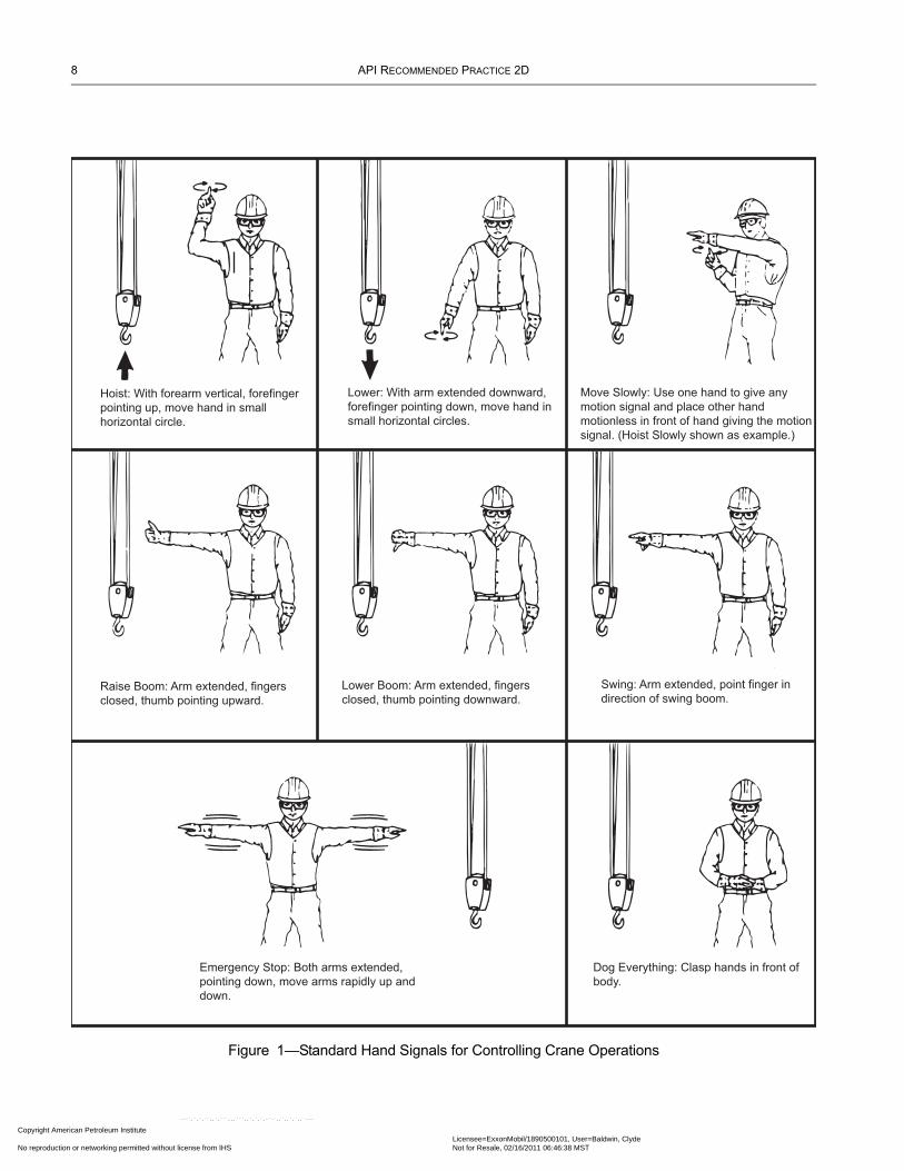
Recommended standard hand signals are identified in Figure 1. The use of these recommended standard hand signals is encouraged.
3.3.3 Special Signals
For operations not covered in Figure 1, or for special conditions, additions or modifications to the recommended standard signals may be required. In such cases, these special signals should be agreed upon in advance by the Crane Operator and the designated signal person and should not be in conflict with, or have the potential to be confused with, standard signals.
3.3.4 Instructions
If it is desired to give instructions to the Crane Operator other than those provided by the established signal system, the crane motion should be stopped.
3.3.5 Signaling
When operations are required to be controlled by signals, a designated signal person should be assigned to work with the crane. The designated signal person should:
a. Be qualified by experience with the operations and knowledgeable of the standard hand signals as shown in Figure 1.b. Be in clear view of the Crane Operator to ensure that their signals may be seen. Their position should give them a clear view of the load, crane, personnel, and area of operation. If the Crane Operator’s view of the primary signal person is obstructed, a sec-ondary signal person should be provided.
3.4 PERSONNEL TRANSFER
3.4.1 All hooks used for support of personnel shall have an operable latch. A crane hook that may be closed and locked, with a pinned or positive locking device, eliminating the hook throat opening, shall be used for any personnel lifts. Additionally, a hook with a purposefully designed lifting eye integral to the hook may be used in conjunction with a shackle that may be pinned to pre-vent opening. These hooks are designed to prevent the personnel basket sling from coming off the hook accidentally.
n Petroleum Institute nder license with API Licensee=ExxonMobil/1890500101, User=Baldwin, Clyde
Not for Resale, 02/16/2011 06:46:38 MSTr networking permitted without license from IHS
--``,`,`,``,,`,```,,,```,,`,`,`,-`-`,,`,,`,`,,`---
8 API RECOMMENDED PRACTICE 2D
Copyright AmProvided by No reproduc
Figure 1—Standard Hand Signals for Controlling Crane Operations
Hoist: With forearm vertical, forefinger
pointing up, move hand in small
horizontal circle.
Lower: With arm extended downward,
forefinger pointing down, move hand in
small horizontal circles.
Move Slowly: Use one hand to give any
motion signal and place other hand
motionless in front of hand giving the motion
signal. (Hoist Slowly shown as example.)
Raise Boom: Arm extended, fingers
closed, thumb pointing upward.
Lower Boom: Arm extended, fingers
closed, thumb pointing downward.
Swing: Arm extended, point finger in
direction of swing boom.
Emergency Stop: Both arms extended,
pointing down, move arms rapidly up and
down.
Dog Everything: Clasp hands in front of
body.
erican Petroleum Institute IHS under license with API Licensee=ExxonMobil/1890500101, User=Baldwin, Clyde
Not for Resale, 02/16/2011 06:46:38 MSTtion or networking permitted without license from IHS
--``,`,`,``,,`,```,,,```,,`,`,`,-`-`,,`,,`,`,,`---
RECOMMENDED PRACTICE FOR OPERATION AND MAINTENANCE OF OFFSHORE CRANES 9
Copyright AmericaProvided by IHS uNo reproduction o
3.4.2 When making personnel lifts, the load shall be under control in both up and down directions.
3.4.3 All personnel to be lifted on a personnel carrier or basket shall use approved personnel flotation devices (PFD) when being lifted or lowered over water. Personnel riding on net type personnel baskets should stand on the outer rim facing inward or as provided by manufacturer’s instructions.
3.4.4 The weight of the loaded personnel carrier or basket should not exceed the Personnel Rated Load as defined by API Spec 2C, latest edition.
See Appendix B.3.4 for additional comments.
3.5 MISCELLANEOUS
3.5.1 Refueling
a. Cranes should not be refueled with the engine running.b. Fuel tanks shall be filled in a manner that fuel spills or overflows will not run onto engine, exhaust, or electrical equipment, and should have spill containment to provide environmental protection.
3.5.2 Fire Extinguishers
a. Fire extinguishers shall be kept in the cab or vicinity of the crane and be of a size and type not less than specified by the proper authorities.b. Personnel who are expected to respond to fires should be trained in the use of fire extinguishers as described in 3.5.2a.
3.5.3 Load Test
a. A crane load test is required under the following conditions:1. New cranes being placed into service.2. Cranes that are being permanently relocated.3. Temporary cranes after each rig-up or relocation.
Note: If a physical change is made to the crane that would enable lifting over the original load-tested weight, the manufacturer or other qualified sources, such as an API-licensed 2C Crane Manufacturer, Authorized Surveyor or an engineer experienced in the design of the crane as deter-mined by the Crane Owner should be consulted for the appropriate action (i.e., new load chart, load test, etc.).
See Appendix E for additional information on load testing.
3.5.4 Pull Test
a. A pull test is conducted at the Crane Owner or Crane Owner representative’s discretion and is not a requirement of this RP. b. A “pull test” is defined as a load that is applied to the crane structure that will not exceed 100% of the crane’s onboard rated capacity as identified on the crane’s load chart. THIS IS NOT A LOAD TEST AS DESCRIBED IN 3.5.3 AND APPENDIX E.c. When the Crane Owner or Crane Owner’s representative elects to have a crane pull tested, a calibrated dynamometer or a known suspended weight should be used and the pull test should be held for a minimum of 5 minutes. Upon the completion of the pull test, a Qualified Crane Operator or Qualified Inspector should perform a pre-use inspection of the crane to assure no damage occurred during the test.
n Petroleum Institute nder license with API Licensee=ExxonMobil/1890500101, User=Baldwin, Clyde
Not for Resale, 02/16/2011 06:46:38 MSTr networking permitted without license from IHS
--``,`,`,``,,`,```,,,```,,`,`,`,-`-`,,`,,`,`,,`---
10 API RECOMMENDED PRACTICE 2D
Copyright AmProvided by No reproduc
4 Inspection, Testing, and Maintenance4.1 USAGE AND INSPECTION
See Appendix C for detailed information.
4.1.1 Crane Usage Categories
Inspection procedures for cranes in-service are divided into three general categories based upon their usage or duty cycle, which in turn determines different, appropriate intervals at which inspections are to be performed. The usage categories should be assigned by the users on a consistent crane-by-crane basis. The intent is to measure their duty cycle as the duration of time for which the crane is in actual use. For further guidance, see C.4.1.1. The three crane usage categories are as follows:
4.1.1.1 Infrequent Usage
Infrequent Usage applies to those cranes that are used for 10 hours or less per month, based on the averaged use over a quarter. These cranes are subject to a Pre-use Inspection and an Annual Inspection. Crane usage should be reviewed on a periodic basis by the Crane Owner to ensure proper inspection intervals.
Note: Special attention should be given to wire rope on these cranes during pre-use inspections.
4.1.1.2 Moderate Usage
Moderate Usage applies to those cranes that are used for more than 10 hours but for less than 50 hours per month, based on the averaged use over a quarter. These cranes are subject to Pre-use, Quarterly, and Annual Inspections. Crane usage should be reviewed on a periodic basis by the Crane Owner to ensure proper inspection intervals.
4.1.1.3 Heavy Usage
Heavy Usage applies to those cranes that are used for 50 hours or more per month. These cranes are subject to Pre-use, Monthly, Quarterly, and Annual Inspections. Cranes assigned this category usage need not be reviewed to determine the number of hours used each month unless otherwise specified by the Crane Owner.
4.1.2 Inspection Categories
All cranes should receive inspections in accordance with the categories described below. These inspections are more clearly defined in Appendix C of this RP. These inspection requirements apply to all cranes including those installed for temporary use. These inspection guidelines are minimum requirements. The Crane Owner should determine the actual scope of the inspections, with input from manufacturers and other relevant sources, as appropriate.
4.1.2.1 Initial Inspection
Initial Inspections apply to cranes that are new and are being placed into service, cranes that are being permanently relocated, and temporary cranes. A Qualified Inspector shall perform these inspections. Every Initial Inspection shall include a load test per-formed per the procedures outlined in Appendix E.
4.1.2.2 Pre-use Inspection
The Pre-use Inspection shall be performed and documented prior to the first crane use of the day, prior to or during each change in Crane Operator, and then as the Qualified Crane Operator deems necessary during the day for extended operations. A Qualified Crane Operator shall perform this inspection, and it applies to all cranes, regardless of usage category. A Qualified Inspector may also perform these inspections.
4.1.2.3 Monthly Inspection
The Monthly Inspection shall be performed once per month, for all cranes assigned a Heavy Usage category. A Qualified Crane Operator shall perform this inspection. A Qualified Inspector may also perform these inspections.
--``,`,`,``,,`,```,,,```,,`,`,`,-`-`,,`,,`,`,,`---
erican Petroleum Institute IHS under license with API Licensee=ExxonMobil/1890500101, User=Baldwin, Clyde
Not for Resale, 02/16/2011 06:46:38 MSTtion or networking permitted without license from IHS
RECOMMENDED PRACTICE FOR OPERATION AND MAINTENANCE OF OFFSHORE CRANES 11
Copyright AmericaProvided by IHS uNo reproduction o
4.1.2.4 Quarterly Inspection
The Quarterly Inspection shall be performed once every 3 months for all cranes assigned a Moderate or Heavy Usage category. A Qualified Inspector shall perform this inspection.
4.1.2.5 Annual Inspection
The Annual Inspection shall be performed once every twelve months. A Qualified Inspector shall perform this inspection, and it applies to all cranes, regardless of usage category.
Recommended guidelines for the scopes of each of these inspections may be found in C.4.1.2.
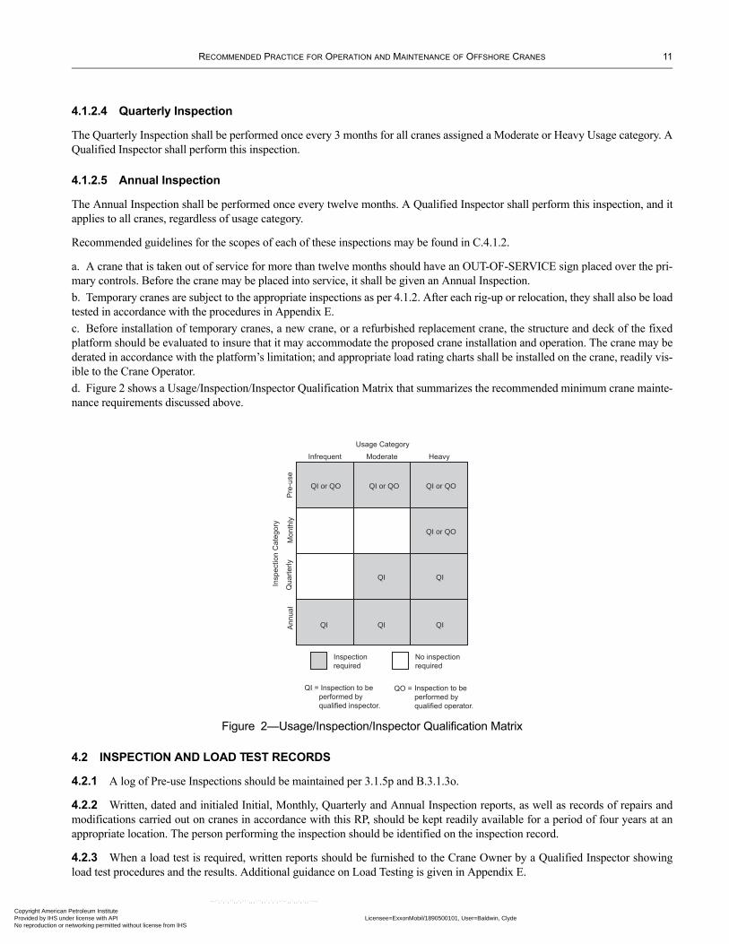
a. A crane that is taken out of service for more than twelve months should have an OUT-OF-SERVICE sign placed over the pri-mary controls. Before the crane may be placed into service, it shall be given an Annual Inspection.b. Temporary cranes are subject to the appropriate inspections as per 4.1.2. After each rig-up or relocation, they shall also be load tested in accordance with the procedures in Appendix E.c. Before installation of temporary cranes, a new crane, or a refurbished replacement crane, the structure and deck of the fixed platform should be evaluated to insure that it may accommodate the proposed crane installation and operation. The crane may be derated in accordance with the platform’s limitation; and appropriate load rating charts shall be installed on the crane, readily vis-ible to the Crane Operator.d. Figure 2 shows a Usage/Inspection/Inspector Qualification Matrix that summarizes the recommended minimum crane mainte-nance requirements discussed above.
Figure 2—Usage/Inspection/Inspector Qualification Matrix
QI or QO QI or QO QI or QO
QI or QO
QIQI
QIQIQI
Infrequent
Usage Category
Moderate Heavy
Pre
-use
Mon
thly
Qua
rterly
Ann
ual
Insp
ectio
n C
ateg
ory
Inspectionrequired
No inspectionrequired
QI = Inspection to be performed by qualified inspector.
QO = Inspection to beperformed by qualified operator.
4.2 INSPECTION AND LOAD TEST RECORDS
4.2.1 A log of Pre-use Inspections should be maintained per 3.1.5p and B.3.1.3o.
4.2.2 Written, dated and initialed Initial, Monthly, Quarterly and Annual Inspection reports, as well as records of repairs and modifications carried out on cranes in accordance with this RP, should be kept readily available for a period of four years at an appropriate location. The person performing the inspection should be identified on the inspection record.
4.2.3 When a load test is required, written reports should be furnished to the Crane Owner by a Qualified Inspector showing load test procedures and the results. Additional guidance on Load Testing is given in Appendix E.
n Petroleum Institute nder license with API Licensee=ExxonMobil/1890500101, User=Baldwin, Clyde
Not for Resale, 02/16/2011 06:46:38 MSTr networking permitted without license from IHS
--``,`,`,``,,`,```,,,```,,`,`,`,-`-`,,`,,`,`,,`---
12 API RECOMMENDED PRACTICE 2D
Copyright AmProvided by No reproduc
4.3 MAINTENANCE
4.3.1 Preventive Maintenance
A preventive maintenance program should be established by the Crane Owner, taking into consideration crane type, frequency of usage, history of maintenance, and manufacturer’s recommendations. Written and dated maintenance records should be readily available for a period of 4 years.
4.3.2 Maintenance Procedure
a. The following precautions, where applicable, should be taken before adjustments, repairs and maintenance are started on a crane.
1. Means of starting should be rendered inoperative.2. Appropriate out-of-service signs should be placed at the control station and/or on the prime mover.3. Additional precautions may be found in F.4.3.2.
b. Adjustments should be made to assure correct functioning of components per the manufacturer’s recommendations.
4.3.3 Repairs and Replacements
a. If unsafe conditions are disclosed by the inspection requirements as outlined in 4.1 of this RP, the crane shall be taken out of service or its operation restricted to eliminate the unsafe condition.b. Repairs or replacements of critical components should be made as soon as practical (see F.4.3.3). c. Written reports should be maintained by the Crane Owner, confirming the adequacy of major repairs or alterations as implemented.d. All major replacement parts should equal or exceed the original equipment manufacturer’s recommendations.e. No welding repairs shall be made to critical components, such as booms and swing circle assemblies, without specific repair procedures and recommendations from the original Crane Manufacturer, or other qualified source (such as an API-licensed 2C Crane Manufacturer, Authorized Surveyor, or an engineer experienced in the design of the crane, as determined by the Crane Owner). Care should be taken to ensure that arcing does not occur across any bearings.f. Field welding shall not be performed on load hooks or sling hooks. Hooks should not be exposed to excessive heat.
4.4 LUBRICATION
The Crane Owner shall consider the crane or component manufacturer’s recommendations as to points and frequency of lubrica-tion, maintenance of lubricant levels, and compatibility of lubricants.
4.5 CRANE RERATING
Cranes shall be rerated and load charts revised as specified in API Spec 2C.
5 Wire Rope and Sling Inspection, Replacement and Maintenance5.1 WIRE ROPE
5.1.1 Introduction
Wire rope is a structural component of the crane requiring periodic replacement. Possible loss of strength may result from wear, abuse and other forms of deterioration. The wire rope shall be carefully selected, inspected and maintained. Rotation-resistant wire rope has special characteristics that require additional precautions. See Appendix G, Wire Rope and Sling Inspection, Replacement and Maintenance and G.5.1.1 for basic information on wire rope construction.
The Qualified Crane Operator or Inspector who determines whether replacement is necessary shall be knowledgeable in the inspection and maintenance of wire rope.
--``,`,`,``,,`,```,,,```,,`,`,`,-`-`,,`,,`,`,,`---
erican Petroleum Institute IHS under license with API Licensee=ExxonMobil/1890500101, User=Baldwin, Clyde
Not for Resale, 02/16/2011 06:46:38 MSTtion or networking permitted without license from IHS
RECOMMENDED PRACTICE FOR OPERATION AND MAINTENANCE OF OFFSHORE CRANES 13
Copyright AmericaProvided by IHS uNo reproduction o
--``,`,`,``,,`,```,,,```,,`,`,`,-`-`,,`,,`,`,,`---
5.1.2 Inspection
a. The wire rope inspection program should be established taking into consideration crane type, frequency of usage, history of maintenance, wire rope manufacturers’ recommendations, and the Crane Manufacturer’s recommendations.b. Visual inspections of wire rope should be performed by a Qualified Crane Operator in Pre-use and Monthly Inspections. Addi-tional wire rope inspection, per G.5.1.2b, should be performed by Qualified Inspectors during Quarterly and Annual Inspections, and as the results of Pre-use and Monthly Inspections may warrant.c. Inspection tools to determine the condition of the wire rope should include, but not be limited to, the following:
1. Steel tape.2. Sheave groove gauges for worn sheaves used in accordance with API RP 9B, latest edition.3. Quality calipers and/or micrometers with at least 1/1,000th of an inch resolution.4. Chalk or tape measure.
d. During Quarterly and Annual Inspections, or when ropes are changed on a crane, a number of areas affecting performance and rope life should be checked and corrective action taken as appropriate (see G.5.1.2b and G.5.1.2d).
5.1.3 Rope Replacement
a. The various rope conditions noted upon inspection should be used to determine continued use or retirement of the rope in question.b. Inspection records should be maintained per 4.2 to determine the time interval for retirement of the rope. Records should be readily available until the specific wire rope is retired. All observed rope deterioration as listed in G.5.1.2b should be recorded on these inspection records.c. Wire rope unfit for use on cranes, slings or other load carrying devices should be removed from service and identified as unfit for use.d. Wire rope replacement criteria are provided in G.5.1.3.
5.1.4 Rope Maintenance
a. Wire rope is a machine with many parts that move and integrate with each other. Care and maintenance of this machine is as important as all other components of the crane.b. Rope should be stored and handled to prevent damage and deterioration. See G.5.1.4b for recommended storage and handling procedures.c. Unreeling or uncoiling of rope should be done as recommended by the rope manufacturer. See Figure G.7 for an example. When unreeling or uncoiling rope, attention should be given to avoid the introduction of kinks or twists into the rope. Rotation-resistant rope may be more susceptible to this type of damage than other rope types.d. Wire rope in the boom hoist and load hoist systems should be installed as recommended by the crane and/or wire rope manu-facturer. See G.5.1.4d for an example of installation guidelines.e. Before cutting a rope, seize the rope at either side of the cut location to prevent unlaying of the strands. Refer to the manufac-turer’s recommendations.f. Care should be taken during installation to avoid contaminating, scraping or nicking the wire rope. Do not bend the rope about small pipe or crane components that might induce kinks or curling.g. Wedge socketing or terminating of the wire rope should be performed or supervised by a Qualified Crane Operator or Quali-fied Inspector.h. Wire rope clips shall be drop-forged steel and shall be single saddle (U-bolt) or double saddle type clips. Malleable cast iron clips shall not be used. For spacing, number of clips, and torque values, refer to the clip manufacturer’s recommendations. Wire rope clips attached with U-bolts shall have the U-bolt over the dead end of the rope and the live rope resting in the clip saddle. Clips shall be tightened evenly to the recommended torque. After the initial load is applied to the rope, the clip nuts shall be retightened to the recommended torque to compensate for any decrease in rope diameter caused by the load. Rope clip nuts should be retightened periodically to compensate for any further decrease in rope diameter during usage. i. Wedge type sockets should be properly installed, per the guidelines of G.5.1.4i.j. Rope should be maintained in a well-lubricated condition to minimize internal and external corrosion or friction. The best pen-etration of lubricant is obtained when the lubricant is applied as the rope passes over a sheave. Lubricants applied in the field should be compatible with the lubricant applied by the rope manufacturer following the recommendations of the rope and/or a Crane Manufacturer. Do not apply used oil because of contamination. See G.5.1.4j for recommended methods of lubrication.
n Petroleum Institute nder license with API Licensee=ExxonMobil/1890500101, User=Baldwin, Clyde
Not for Resale, 02/16/2011 06:46:38 MSTr networking permitted without license from IHS
14 API RECOMMENDED PRACTICE 2D
Copyright AmProvided by No reproduc
5.1.5 Crane Operation
Operation of the crane will affect rope service life. Guidance in G.5.1.5 should be followed when operating the crane.
5.1.6 Wire Rope Testing
A wire rope manufacturer’s break test certificate shall be supplied to the Crane Owner for all running ropes. Tests shall be per-formed as outlined in API Spec 9A, latest edition.
5.1.7 Pendant Lines
a. Each leg of a set of pendant lines should be proof loaded by the pendant line manufacturer in accordance with recognized industry standards.b. Each pendant line should be labeled showing the manufacturer and appropriate working load limits, proof test certification number, length, diameter, and date of proof test.c. Proof test certification documentation should be supplied to the Crane Owner.
5.2 SLINGS
Due to the numerous types of material, construction, combinations and various types of hitches, it is beyond the scope of this RP to list the load ratings of each individual type. The sling manufacturer should be consulted when a question arises concerning sling ratings, use, care and/or inspection. Section G.5.2 lists types of common slings.
5.2.1 Sling Use and Inspection
Section G.5.2.1 provides guidelines on the proper use of slings. Slings shall be inspected and tested in accordance with the ASME B30.9, Wire Rope Sling Users Manual, Recommended Standard Specifications for Synthetic Polyester Roundslings, Recom-mended Standard Specifications for Synthetic Web Slings, latest edition, or other applicable standards (see Appendix H).
a. All slings shall be visually checked prior to use by a Qualified Crane Operator or Qualified Rigger.b. The frequency of documenting sling inspections should be determined by the Crane Owner based on the following:
1. Frequency of sling use.2. Severity of service conditions.3. Nature or type of lifts being made.4. Experience based on service life of slings used in similar applications.
Minimum guidelines for sling inspection frequencies are included within 5.1.2b.
5.2.2 Sling Fabrication and Lifting Procedures
See 5.2.2 for guidelines on sling fabrication and lifting procedures.
5.2.3 Wire Rope Sling Replacement
Deterioration that contributes to loss of the original strength should be taken into consideration and the sling retired as appropri-ate. Refer to the removal criteria of ASME B30.9 and G.5.2.3. Reasons for replacing the sling should include, but not be limited to, the conditions outlined in G.5.2.3. If there is any question relative to the integrity of the sling, the sling should be removed from service and properly disposed of.
5.2.4 Slings Proof Loading and Labeling
a. Slings of all types shall be proof loaded by the sling manufacturer per industry recommendations. See G.5.2.4 for further details.b. All slings, regardless of grade and construction, shall be labeled showing sling manufacturer’s identity and the pertinent work-ing load limits, proof test certification number, length, diameter, and date of proof test.c. Slings of other than wire rope construction shall be used, inspected and tested in accordance with the sling manufacturer and industry recommendations.
--``,`,`,``,,`,```,,,```,,`,`,`,-`-`,,`,,`,`,,`---
erican Petroleum Institute IHS under license with API Licensee=ExxonMobil/1890500101, User=Baldwin, Clyde
Not for Resale, 02/16/2011 06:46:38 MSTtion or networking permitted without license from IHS
Copyright American Petroleum Institute Provided by IHS under license with API No reproduction or networking permitted without lic
--``,`,`,``,,`,```,,,```,,`,`,`,-`-`,,`,,`,`,,`---
APPENDIX A—TRAINING
15
Licensee=ExxonMobil/1890500101, User=Baldwin, ClydeNot for Resale, 02/16/2011 06:46:38 MSTense from IHS

Copyright American Petroleum Institute Provided by IHS under license with API No reproduction or networking permitted without lic
--``,`,`,``,,`,```,,,```,,`,`,`,-`-`,,`,,`,`,,`---
Licensee=ExxonMobil/1890500101, User=Baldwin, ClydeNot for Resale, 02/16/2011 06:46:38 MSTense from IHS
Copyright AmericaProvided by IHS uNo reproduction o
APPENDIX A1—CRANE OPERATOR TRAINING
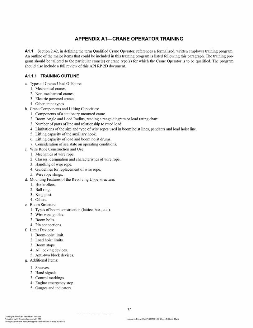
A1.1 Section 2.42, in defining the term Qualified Crane Operator, references a formalized, written employer training program. An outline of the major items that could be included in this training program is listed following this paragraph. The training pro-gram should be tailored to the particular crane(s) or crane type(s) for which the Crane Operator is to be qualified. The program should also include a full review of this API RP 2D document.
A1.1.1 TRAINING OUTLINE
a. Types of Cranes Used Offshore:1. Mechanical cranes.2. Non-mechanical cranes.3. Electric powered cranes.4. Other crane types.
b. Crane Components and Lifting Capacities:1. Components of a stationary mounted crane.2. Boom Angle and Load Radius, reading a range diagram or load rating chart.3. Number of parts of line and relationship to rated load.4. Limitations of the size and type of wire ropes used in boom hoist lines, pendants and load hoist line.5. Lifting capacity of the auxiliary hook.6. Lifting capacity of load and boom hoist drums.7. Consideration of sea state on operating conditions.
c. Wire Rope Construction and Use:1. Mechanics of wire rope.2. Classes, designation and characteristics of wire rope.3. Handling of wire rope.4. Guidelines for replacement of wire rope.5. Wire rope slings.
d. Mounting Features of the Revolving Upperstructure:1. Hookrollers.2. Ball ring.3. King post.4. Others.
e. Boom Structure:1. Types of boom construction (lattice, box, etc.).2. Wire rope guides.3. Boom bolts.4. Pin connections.
f. Limit Devices:1. Boom-hoist limit.2. Load hoist limits.3. Boom stops.4. All locking devices.5. Anti-two block devices.
g. Additional Items:
1. Sheaves.2. Hand signals.3. Control markings.4. Engine emergency stop.5. Gauges and indicators.
17n Petroleum Institute nder license with API Licensee=ExxonMobil/1890500101, User=Baldwin, Clyde
Not for Resale, 02/16/2011 06:46:38 MSTr networking permitted without license from IHS
--``,`,`,``,,`,```,,,```,,`,`,`,-`-`,,`,,`,`,,`---

Copyright AmProvided by No reproduc
--``,`,`,``,,`,```,,,```,,`,`,`,-`-`,,`,,`,`,,`---
erican Petroleum Institute IHS under license with API Licensee=ExxonMobil/1890500101, User=Baldwin, Clyde
Not for Resale, 02/16/2011 06:46:38 MSTtion or networking permitted without license from IHS
Copyright AmericaProvided by IHS uNo reproduction o
--``,`,`,``,,`,```,,,```,,`,`,`,-`-`,,`,,`,`,,`---
APPENDIX A2—CRANE INSPECTOR TRAINING
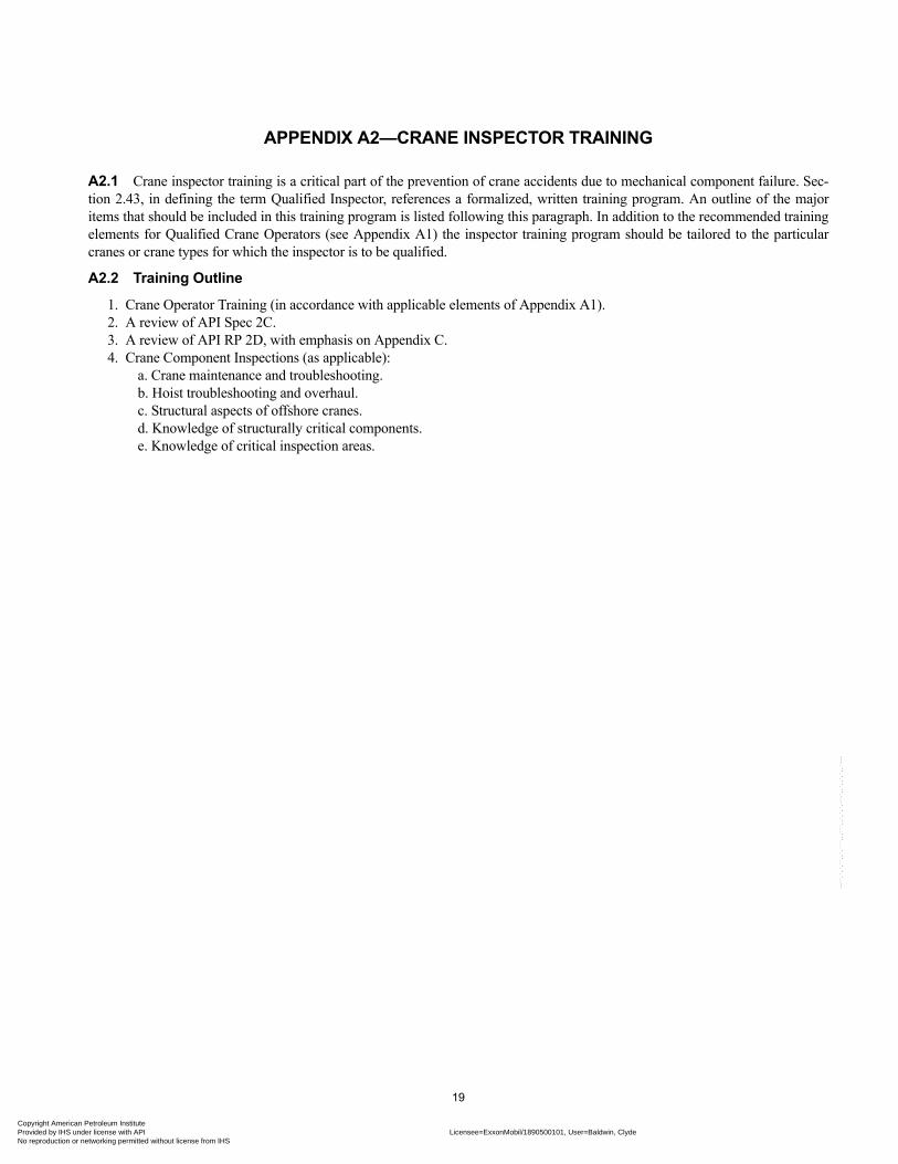
A2.1 Crane inspector training is a critical part of the prevention of crane accidents due to mechanical component failure. Sec-tion 2.43, in defining the term Qualified Inspector, references a formalized, written training program. An outline of the major items that should be included in this training program is listed following this paragraph. In addition to the recommended training elements for Qualified Crane Operators (see Appendix A1) the inspector training program should be tailored to the particular cranes or crane types for which the inspector is to be qualified.
A2.2 Training Outline
1. Crane Operator Training (in accordance with applicable elements of Appendix A1).2. A review of API Spec 2C.3. A review of API RP 2D, with emphasis on Appendix C.4. Crane Component Inspections (as applicable):
a. Crane maintenance and troubleshooting.b. Hoist troubleshooting and overhaul.c. Structural aspects of offshore cranes.d. Knowledge of structurally critical components.e. Knowledge of critical inspection areas.
19
n Petroleum Institute nder license with API Licensee=ExxonMobil/1890500101, User=Baldwin, Clyde
Not for Resale, 02/16/2011 06:46:38 MSTr networking permitted without license from IHS

Copyright AmProvided by No reproduc
erican Petroleum Institute IHS under license with API Licensee=ExxonMobil/1890500101, User=Baldwin, Clyde
Not for Resale, 02/16/2011 06:46:38 MSTtion or networking permitted without license from IHS
--``,`,`,``,,`,```,,,```,,`,`,`,-`-`,,`,,`,`,,`---
Copyright AmericaProvided by IHS uNo reproduction o
APPENDIX A3—RIGGER TRAINING
A.2.3 An important part of crane safety is proper training of rigger personnel. An outline of items that should be considered for a Qualified Rigger training program is listed in A.2.3.1.
A.2.3.1 Training Outline
a. Rigging Hardware:1. Sheaves, blocks.2. Hooks, latches.3. Rings, links, swivels.4. Shackles.5. Turnbuckles.6. Spreader and equalizer beams.7. Cable clips.8. Pad eyes, eyebolts, and other attachment points.
b. Slings:1. Sling configuration.2. Sling angle.3. Rated load4. Sling types (synthetic, wire, chain, etc.).5. Cargo nets, personnel baskets, and other basket types.
c. Procedures and Precautions:1. Load control/taglines.2. Lift planning (load weight, center of gravity, etc.).3. Sling Inspection/rejection criteria.4. Unbinding loads.5. Personnel transfer.6. Sling handling and storage.
d. Rigging Basics:1. Pinch points/body position.2. Personal Protective Equipment (PPE).3. Signals/communications.4. Load stability.
--``,`,`,``,,`,```,,,```,,`,`,`,-`-`,,`,,`,`,,`---
21
n Petroleum Institute nder license with API Licensee=ExxonMobil/1890500101, User=Baldwin, Clyde
Not for Resale, 02/16/2011 06:46:38 MSTr networking permitted without license from IHS

Copyright AmProvided by No reproduc
--``,`,`,``,,`,```,,,```,,`,`,`,-`-`,,`,,`,`,,`---
erican Petroleum Institute IHS under license with API Licensee=ExxonMobil/1890500101, User=Baldwin, Clyde
Not for Resale, 02/16/2011 06:46:38 MSTtion or networking permitted without license from IHS
Copyright AmericaProvided by IHS uNo reproduction o
APPENDIX B—CRANE OPERATION
B.3.1.2c “Hands On” proficiency is defined as a physical means of verifying the following:
1. Crane Operator’s dexterity and coordination.2. Crane Operator’s familiarity with overall machine functions and characteristics.
“Hands On” proficiency is the last segment of Crane Operator qualification training. It should be held on a crane similar to the type of crane to be operated by the qualifying Crane Operator, in order to allow the qualifying Crane Operator to demonstrate his or her ability.
B.3.1.3a During periods of bad weather, such as lightning or high winds, or where the Crane Operator’s ability to see the signal person is impaired by darkness, fog, rain, etc., crane operations should be restricted, at the Crane Operator’s discretion.
B.3.1.3o A “log” is defined as: A record, a record book, a logbook, a computerized database or an electronic data collector.
Note: This log should be used for Pre-use Inspection reporting, and may also be used for documenting crane usage.
The crane cab, a weather tight enclosure on the crane, or inside the nearest building are examples of appropriate locations for stor-age of logs.
B.3.2.1c “Hook load” is defined as the load being lifted plus the weight of the slings and rigging. Hook load may or may not include the weight of the hook block and wire rope. This may be determined from the crane’s load rating chart. Examples of ways to determine load weight are: Weight indicators, scales, and shorebase weighing.
B.3.2.2c Sling use guidelines are:
1. Slings, their fittings and fasteners, prior to use, should be inspected and retired in accordance with 5.2.1.2. Suitable protection should be provided between the sling and sharp surfaces of the load to be lifted.3. Proper storage should be provided for slings while not in use. Special considerations should be given in high heat areas where elevated corrosion and loss of lubrication may contribute to reduced service life.4. Slings should never be choked in the splice.5. Sharp kinks or knots should not be permitted in wire rope slings.6. Loads should not be lifted with one leg of a multi-leg sling until the unused legs are secured.
B.3.2.3 Moving the Load
Guidelines for moving the load are as follows:
The Qualified Crane Operator and the designated signal person directing the lift, if utilized, should determine that:
1. The load is secured and properly balanced in the appropriate sling or lifting device before it is lifted.2. The lift and swing paths are clear of obstructions and personnel.
Before starting to lift, the following conditions shall be verified:
1. The correct slings have been selected for the weight to be lifted.2. The load is free to be lifted.3. Multiple part lines are not twisted around each other in such a manner that all of the lines will not separate upon application of lift.4. The hook is brought over the load in such a manner as to minimize swinging.5. If there is a slack rope condition, the rope is properly seated on the drum and in the sheaves.
During lifting, care shall be taken that:
1. Acceleration or deceleration of the moving load is accomplished in a smooth manner.2. The Crane Operator should be aware of the effect of the velocity and weight of the load when lowering at high speeds to minimize shock loading.3. Load, boom, or other parts of the machine do not contact any obstruction.
--``,`,`,``,,`,```,,,```,,`,`,`,-`-`,,`,,`,`,,`---
23
n Petroleum Institute nder license with API Licensee=ExxonMobil/1890500101, User=Baldwin, Clyde
Not for Resale, 02/16/2011 06:46:38 MSTr networking permitted without license from IHS
24 API RECOMMENDED PRACTICE 2D
Copyright AmProvided by No reproduc
The Crane Operator should engage the controls smoothly to avoid excessive stress on crane machinery.
When rotating the crane, sudden starts and stops should be avoided. Rotational speed should be such that the load does not swing out beyond the radius at which it may be controlled.
B.3.4 PERSONNEL TRANSFER
The Crane Operator, while transferring personnel between vessels or from a vessel to a platform, should raise the personnel car-rier only high enough off the deck to clear all obstructions: swing the personnel carrier over the water; raise or lower it in such a manner as to minimize swinging; position it slightly above the landing area; and gently lower it to the deck.
A loaded personnel carrier should not be raised or lowered directly over a vessel. If the crane cannot swing the loaded personnel carrier clear of the vessel beneath, the vessel, where practical, should be moved out from under the personnel carrier.
Personnel carriers should be of a design and in a condition suitable for the intended purpose.
--``,`,`,``,,`,```,,,```,,`,`,`,-`-`,,`,,`,`,,`---
erican Petroleum Institute IHS under license with API Licensee=ExxonMobil/1890500101, User=Baldwin, Clyde
Not for Resale, 02/16/2011 06:46:38 MSTtion or networking permitted without license from IHS
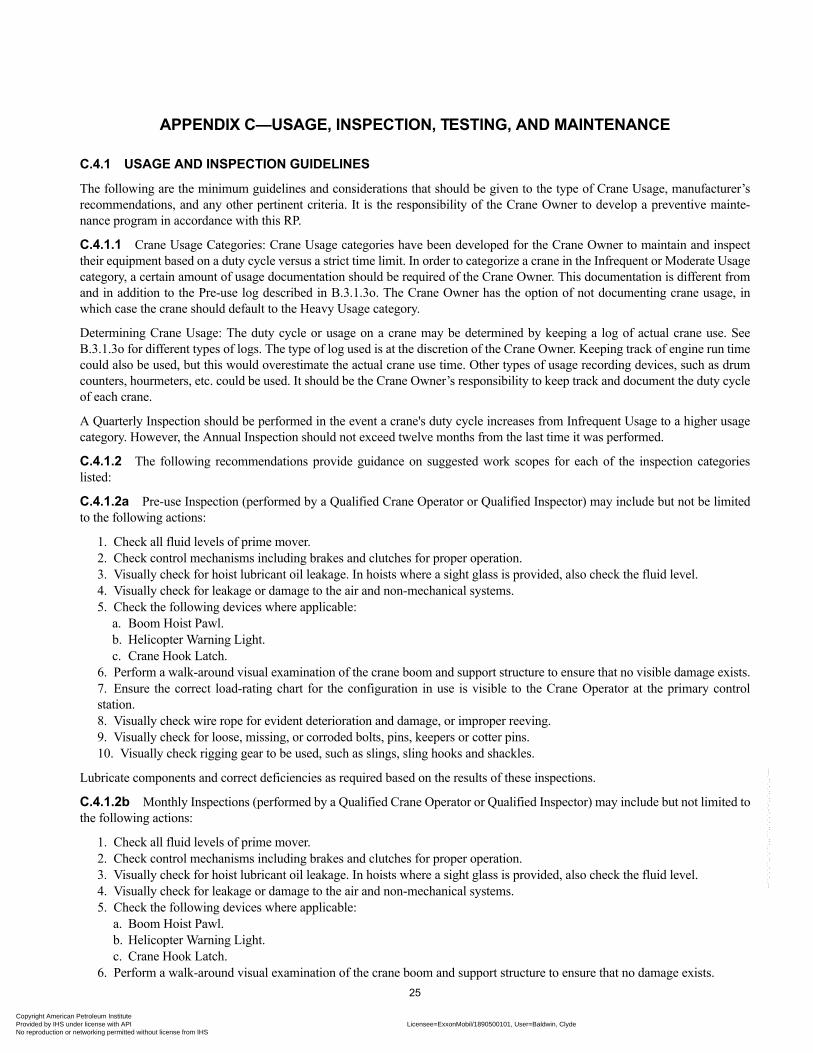
Copyright AmericaProvided by IHS uNo reproduction o
--``,`,`,``,,`,```,,,```,,`,`,`,-`-`,,`,,`,`,,`---
APPENDIX C—USAGE, INSPECTION, TESTING, AND MAINTENANCE
C.4.1 USAGE AND INSPECTION GUIDELINES
The following are the minimum guidelines and considerations that should be given to the type of Crane Usage, manufacturer’s recommendations, and any other pertinent criteria. It is the responsibility of the Crane Owner to develop a preventive mainte-nance program in accordance with this RP.
C.4.1.1 Crane Usage Categories: Crane Usage categories have been developed for the Crane Owner to maintain and inspect their equipment based on a duty cycle versus a strict time limit. In order to categorize a crane in the Infrequent or Moderate Usage category, a certain amount of usage documentation should be required of the Crane Owner. This documentation is different from and in addition to the Pre-use log described in B.3.1.3o. The Crane Owner has the option of not documenting crane usage, in which case the crane should default to the Heavy Usage category.
Determining Crane Usage: The duty cycle or usage on a crane may be determined by keeping a log of actual crane use. See B.3.1.3o for different types of logs. The type of log used is at the discretion of the Crane Owner. Keeping track of engine run time could also be used, but this would overestimate the actual crane use time. Other types of usage recording devices, such as drum counters, hourmeters, etc. could be used. It should be the Crane Owner’s responsibility to keep track and document the duty cycle of each crane.
A Quarterly Inspection should be performed in the event a crane's duty cycle increases from Infrequent Usage to a higher usage category. However, the Annual Inspection should not exceed twelve months from the last time it was performed.
C.4.1.2 The following recommendations provide guidance on suggested work scopes for each of the inspection categories listed:
C.4.1.2a Pre-use Inspection (performed by a Qualified Crane Operator or Qualified Inspector) may include but not be limited to the following actions:
1. Check all fluid levels of prime mover.2. Check control mechanisms including brakes and clutches for proper operation.3. Visually check for hoist lubricant oil leakage. In hoists where a sight glass is provided, also check the fluid level.4. Visually check for leakage or damage to the air and non-mechanical systems.5. Check the following devices where applicable:
a. Boom Hoist Pawl.b. Helicopter Warning Light.c. Crane Hook Latch.
6. Perform a walk-around visual examination of the crane boom and support structure to ensure that no visible damage exists.7. Ensure the correct load-rating chart for the configuration in use is visible to the Crane Operator at the primary control station.8. Visually check wire rope for evident deterioration and damage, or improper reeving.9. Visually check for loose, missing, or corroded bolts, pins, keepers or cotter pins.10. Visually check rigging gear to be used, such as slings, sling hooks and shackles.
Lubricate components and correct deficiencies as required based on the results of these inspections.
C.4.1.2b Monthly Inspections (performed by a Qualified Crane Operator or Qualified Inspector) may include but not limited to the following actions:
1. Check all fluid levels of prime mover.2. Check control mechanisms including brakes and clutches for proper operation.3. Visually check for hoist lubricant oil leakage. In hoists where a sight glass is provided, also check the fluid level.4. Visually check for leakage or damage to the air and non-mechanical systems.5. Check the following devices where applicable:
a. Boom Hoist Pawl.b. Helicopter Warning Light.c. Crane Hook Latch.
6. Perform a walk-around visual examination of the crane boom and support structure to ensure that no damage exists.
25n Petroleum Institute nder license with API Licensee=ExxonMobil/1890500101, User=Baldwin, Clyde
Not for Resale, 02/16/2011 06:46:38 MSTr networking permitted without license from IHS
26 API RECOMMENDED PRACTICE 2D
Copyright AmProvided by No reproduc
7. Ensure the correct load-rating chart for the configuration in use is visible to the Crane Operator at the primary control station.8. Visually check wire rope for evident deterioration and damage, or improper reeving.9. Visually check for loose, missing, or corroded bolts, pins, keepers or cotter pins.10. Visually check rigging gear to be used, such as slings, sling hooks and shackles.11. Further check all control mechanisms for proper adjustment, excessive wear of components, and contamination by foreign matter.12. Check appropriate electrical apparatus for proper function.13. Check boom hoist limit and anti-two block devices for proper operation. Care should be exercised to prevent damage to crane components.
Lubricate components and correct deficiencies as required based on the results of these inspections. Document these results per 4.2.2.
C.4.1.2c Quarterly Inspections (performed by a Qualified Inspector) may include but not be limited to the following actions:
1. Check all fluid levels of prime mover.2. Check control mechanisms including brakes and clutches for proper operation.3. Visually check for hoist lubricant oil leakage. In hoists where a sight glass is provided, also check the fluid level.4. Visually check for leakage or damage to the air and non-mechanical systems.5. Check the following devices where applicable:
a. Boom Hoist Pawl.b. Helicopter Warning Light.c. Crane Hook Latch.
6. Perform a walk-around visual examination of the crane boom and support structure to ensure that no visual damage exists.7. Ensure the correct load-rating chart for the configuration in use is visible to the Crane Operator at the primary control station.8. Visually check wire rope for evident deterioration and damage, or improper reeving.9. Visually check for loose, missing, or corroded bolts, pins, keepers or cotter pins.10. Visually check rigging gear to be used, such as slings, sling hooks and shackles.11. Further check all control mechanisms for proper adjustment, excessive wear of components, and contamination by foreign matter.12. Check appropriate electrical apparatus for proper function.13. Check boom hoist limit and anti-two block devices for proper operation. Care should be exercised to prevent damage to crane components.14. Boom should be inspected for bent chord members, missing or broken lacing and cracked welds on critical members. Boom section end connections should be inspected for cracked welds, deformation and corrosion.15. Check boom angle/radius indicators over full range for accuracy.16. Sheaves should be inspected for wear, cracks, and rope path alignment and bearing condition.17. Check power plants for proper performance compliance with safety requirements.18. Check belts and chains for proper adjustment.19. Visually check crane hooks for deformation, and discard if deformations exceed those manufacturer’s recommendations.20. Inspect wire rope as per 5.1.2.21. Check lubricant level in all hoists and slew drives, including those not fitted with sight glasses.
Lubricate components and correct deficiencies as required based on the results of these inspections. Document these results per 4.2.2. Oil sample analysis, as suggested by the hoist manufacturer, is intended primarily to evaluate its mechanical integrity. Oil sample analysis need not necessarily mean a laboratory analysis. It may be effectively achieved by qualitative tests performed in the field by a Qualified Inspector or Crane Operator (such as cheese cloth, smell and texture tests).
C.4.1.2d Annual Inspections (performed by a Qualified Inspector) will include Pre-use, Monthly, and Quarterly Inspections, as well as inspections of critical crane components. A basic guideline for Annual Inspections should consider, but not be limited to, the following:
1. Check all fluid levels of prime mover.2. Check control mechanisms including brakes and clutches for proper operation.3. Visually check for hoist lubricant oil leakage. In hoists where a sight glass is provided, also check the fluid level.
erican Petroleum Institute IHS under license with API Licensee=ExxonMobil/1890500101, User=Baldwin, Clyde
Not for Resale, 02/16/2011 06:46:38 MSTtion or networking permitted without license from IHS
--``,`,`,``,,`,```,,,```,,`,`,`,-`-`,,`,,`,`,,`---

RECOMMENDED PRACTICE FOR OPERATION AND MAINTENANCE OF OFFSHORE CRANES 27
Copyright AmericaProvided by IHS uNo reproduction o
4. Visually check for leakage or damage to the air and non-mechanical systems.5. Check the following devices where applicable:
a. Boom Hoist Pawl.b. Helicopter Warning Light.c. Crane Hook Latch.
6. Perform a walk-around visual examination of the crane boom and support structure to ensure that no visible damage exists.7. Ensure the correct load-rating chart for the configuration in use is visible to the Crane Operator at the primary control station.8. Visually check wire rope for evident deterioration and damage, or improper reeving.9. Visually check for loose, missing, or corroded bolts, pins, keepers or cotter pins.10. Visually check rigging gear to be used, such as slings, sling hooks and shackles.11. Further check all control mechanisms for proper adjustment, excessive wear of components, and contamination by foreign matter.12. Check appropriate electrical apparatus for proper function.13. Check boom hoist limit and anti-two block devices for proper operation. Care should be exercised to prevent damage to crane components.14. Boom should be inspected for bent chord members, missing or broken lacing and cracked welds on critical members. Boom section end connections should be inspected for cracked welds, deformation and corrosion.15. Check boom angle/radius indicators over full range for accuracy.16. Sheaves should be inspected for wear, cracks, and rope path alignment and bearing condition.17. Check power plants for proper performance compliance with safety requirements.18. Check belts and chains for proper adjustment.19. Visually check crane hooks for deformation, and discard if deformations exceed those manufacturers’ recommendations.20. Inspect wire rope as per 5.1.2.21. Check lubricant level in all hoists and slew drives, including those not fitted with sight glasses.
Lubricate components and correct deficiencies as required based on the results of these inspections. Document these results per 4.2.2. Oil sample analysis, as suggested by the hoist manufacturer, is intended primarily to evaluate its mechanical integrity. Oil sample analysis need not necessarily mean a laboratory analysis. It may be effectively achieved by qualitative tests performed in the field by a Qualified Inspector or Crane Operator (such as cheese cloth, smell and texture tests).
Inspection of critical crane components: The Annual Inspection of critical components appropriate for an individual machine will differ, depending on the crane type and design of the individual components. A basic guideline for inspection of critical crane components should consider but not be limited to the following:
22. Hoist Assemblies—Annual Inspection and maintenance of the hoist should be determined by the Crane Owner as a func-tion of the hoist type, past and anticipated duty cycle, and condition. The quality of the hoist lubricant is considered a primary indicator of the mechanical integrity of the hoist. Brakes should be tested by stalling the drive. See Appendix D, Spring-set Hoist Brakes, for additional recommendations for spring-set hoist brakes.23. Foundation—Weldments in the crane’s pedestal and supporting deck structure should be visually examined for fracture, deformation and corrosion. Special attention should be paid to areas of rust and cracked paint.24. Swing Circle Assembly—The swing circle assembly is the connecting component between the crane revolving upper-structure and the pedestal. Consequently, regular inspections are paramount to insure a long and safe operational life.
There are 3 main types of swing circle assemblies typically used on pedestal-mounted cranes:
• Hook and Roller Assemblies.• King Posts.• Ball/Roller Bearings.
The inspection procedure for each varies significantly and should be tailored, not only to fit the type of swing circle assembly, but also for the physical and operational environment of each particular crane and platform.
Regardless of the type of swing circle assembly, the objective of any inspection is to determine and monitor wear, fatigue, corro-sion, and the overall operational condition. The crane and swing circle assembly manufacturers are the best sources for informa-tion in developing the inspection program. The following are suggested inspection guidelines for each type of swing circle assembly.
--``,`,`,``,,`,```,,,```,,`,`,`,-`-`,,`,,`,`,,`---
n Petroleum Institute nder license with API Licensee=ExxonMobil/1890500101, User=Baldwin, Clyde
Not for Resale, 02/16/2011 06:46:38 MSTr networking permitted without license from IHS
28 API RECOMMENDED PRACTICE 2D
Copyright AmProvided by No reproduc
--``,`,`,``,,`,```,,,```,,`,`,`,-`-`,,`,,`,`,,`---
Hook and Roller AssembliesRing Gear:
a. Center Pin and Bushing condition should be verified and monitored for wear. Center Pin wear is generally due to improperly or unevenly adjusted Hook Rollers.b. Proper lubrication of Center Pin Bushing should be verified.c. Obvious wear between ring gear teeth and swing pinion gear would indicate Center Pin wear and improperly adjusted Hook Rollers.d. Excessive lateral wallowing, wobbling, or loud popping noise of machine base or frame indicates Center Pin Bushing wear.
Hook Rollers:
a. Hook Rollers to turntable clearance should not exceed manufacturer specifications.b. Hook Rollers should be evenly adjusted to minimize uneven stress and wear on Center Pin and Center Pin Bushing.c. Hook Roller path should be smooth, flat, and have no ridges or dents that would cause uneven load distribution.d. Hook Rollers should be concentric with no flat spots.e. Bearings should be well lubricated and should roll smoothly with no noticeable popping or grinding noise.
Hook Roller Brackets, Bracket Pads, and Bolts:
a. Machine should be tilted fully in both directions noting any deflection between the Hook Roller Bracket and the machined sur-face of the main frame pad where the Hook Roller Bracket mounts. Consult manufacturer for tolerances.
Note: Forged castings that comprises Hook Roller Brackets very seldom bend or distort; i.e., the main frame generally yields, thus causing obvi-ous deflection or gap.
b. Hook Roller Bracket Bolts should be checked for proper bolt torque, excess stretching, excess rust pitting, improper size, etc.
King PostBearing areas of the crane should be inspected to assure that there is no significant wear or damage to either the rotating or sta-tionary load bearing members, that left uncorrected, might result in a loss of structural integrity of the mounting system. The King Post crane inspection procedure will depend on the design of the crane being inspected and should be done in accordance with the manufacturer’s recommendations. The inspection should include but not be limited to the following:
• Upper thrust bearing.• Upper radial bearing.• Lower thrust bearings or radial bearings.• King pin wear and condition.• Lower king post radial bearings: The radial bearings condition is critical as it protects the king post from the lower thrust
rollers or radial bearings. On cranes not equipped with wear bearings or wear material, the wear zone on the king post shall be carefully monitored to ensure the structural integrity of the king post.
• King post-to-platform structural connection.
Ball/Roller BearingThis type of swing circle assembly is either bolted and/or welded to the pedestal and rotating crane turntable.
The 3 major inspections that should be performed are for a) bearing wear, b) crane/bearing connection integrity, and c) operating characteristics.
1. Bearing Wear
The wear in the bearing must be monitored to determine its expected service life. The wear measurement may be performed in a number of ways. Some of which are as follows:
Wear Assessment by Grease Sample Analysis. Wear may be monitored by periodic grease sample analysis as describe in this section. Grease samples should be collected every twelve months as a minimum and the results of the analysis recorded; this period should be shortened if obvious metal or contaminants are present.
erican Petroleum Institute IHS under license with API Licensee=ExxonMobil/1890500101, User=Baldwin, Clyde
Not for Resale, 02/16/2011 06:46:38 MSTtion or networking permitted without license from IHS
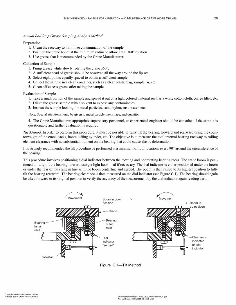
RECOMMENDED PRACTICE FOR OPERATION AND MAINTENANCE OF OFFSHORE CRANES 29
Copyright AmericaProvided by IHS uNo reproduction o
Annual Ball Ring Grease Sampling Analysis Method:
Preparation1. Clean the raceway to minimize contamination of the sample.2. Position the crane boom at the minimum radius to allow a full 360° rotation.3. Use grease that is recommended by the Crane Manufacturer.
Collection of Sample1. Pump grease while slowly rotating the crane 360°.2. A sufficient bead of grease should be observed all the way around the lip seal.3. Select eight points equally spaced to obtain a sufficient sample.4. Collect the sample in a clean container, such as a clear plastic bag, sample jar, etc.5. Clean off excess grease after taking the sample.
Evaluation of Sample1. Take a small portion of the sample and spread it out on a light colored material such as a white cotton cloth, coffee filter, etc.2. Dilute the grease sample with a solvent to expose any contaminates.3. Inspect the sample looking for metal particles, sand, nylon, rust, water, etc.
Note: Special attention should be given to metal particle size, shape, and quantity.
4. The Crane Manufacturer, appropriate supervisory personnel, or experienced engineer should be consulted if the sample is questionable and further evaluation is required.
Tilt Method. In order to perform this procedure, it must be possible to fully tilt the bearing forward and rearward using the coun-terweight of the crane, jacks, boom luffing cylinder, etc. The objective is to measure the total internal bearing raceway to rolling element clearance with no substantial moment on the bearing that could cause elastic deformation.
It is strongly recommended the tilt procedure be performed at a minimum of four locations every 90° around the circumference of the bearing.
This procedure involves positioning a dial indicator between the rotating and nonrotating bearing races. The crane boom is posi-tioned to fully tilt the bearing forward using a light hook load if necessary. The dial indicator is either positioned under the boom or under the rear of the crane in line with the boom centerline and zeroed. The boom is then raised to its highest position to fully tilt the bearing rearward. The bearing clearance is then measured on the dial indicator (see Figure C.1). The bearing should again be tilted forward to its original position to verify the accuracy of the measurement by the dial indicator again reading zero.
Figure C.1—Tilt Method
Movement
Bearing
inner
race
Pedestal
Dial
indicator
“zeroed”
Bearing
outer
race
Crane
Boom in down
position
Movement
Boom in
up position
Clearance
indicated
on dial
indicator
--``,`,`,``,,`,```,,,```,,`,`,`,-`-`,,`,,`,`,,`---
n Petroleum Institute nder license with API Licensee=ExxonMobil/1890500101, User=Baldwin, Clyde
Not for Resale, 02/16/2011 06:46:38 MSTr networking permitted without license from IHS
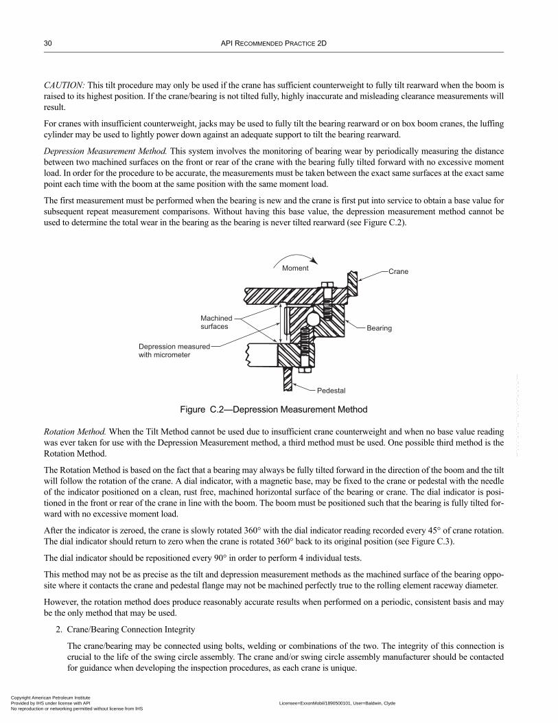
30 API RECOMMENDED PRACTICE 2D
Copyright AmProvided by No reproduc
--``,`,`,``,,`,```,,,```,,`,`,`,-`-`,,`,,`,`,,`---
CAUTION: This tilt procedure may only be used if the crane has sufficient counterweight to fully tilt rearward when the boom is raised to its highest position. If the crane/bearing is not tilted fully, highly inaccurate and misleading clearance measurements will result.
For cranes with insufficient counterweight, jacks may be used to fully tilt the bearing rearward or on box boom cranes, the luffing cylinder may be used to lightly power down against an adequate support to tilt the bearing rearward.
Depression Measurement Method. This system involves the monitoring of bearing wear by periodically measuring the distance between two machined surfaces on the front or rear of the crane with the bearing fully tilted forward with no excessive moment load. In order for the procedure to be accurate, the measurements must be taken between the exact same surfaces at the exact same point each time with the boom at the same position with the same moment load.
The first measurement must be performed when the bearing is new and the crane is first put into service to obtain a base value for subsequent repeat measurement comparisons. Without having this base value, the depression measurement method cannot be used to determine the total wear in the bearing as the bearing is never tilted rearward (see Figure C.2).
Figure C.2—Depression Measurement Method
Moment Crane
Bearing
Pedestal
Machinedsurfaces
Depression measuredwith micrometer
Rotation Method. When the Tilt Method cannot be used due to insufficient crane counterweight and when no base value reading was ever taken for use with the Depression Measurement method, a third method must be used. One possible third method is the Rotation Method.
The Rotation Method is based on the fact that a bearing may always be fully tilted forward in the direction of the boom and the tilt will follow the rotation of the crane. A dial indicator, with a magnetic base, may be fixed to the crane or pedestal with the needle of the indicator positioned on a clean, rust free, machined horizontal surface of the bearing or crane. The dial indicator is posi-tioned in the front or rear of the crane in line with the boom. The boom must be positioned such that the bearing is fully tilted for-ward with no excessive moment load.
After the indicator is zeroed, the crane is slowly rotated 360° with the dial indicator reading recorded every 45° of crane rotation. The dial indicator should return to zero when the crane is rotated 360° back to its original position (see Figure C.3).
The dial indicator should be repositioned every 90° in order to perform 4 individual tests.
This method may not be as precise as the tilt and depression measurement methods as the machined surface of the bearing oppo-site where it contacts the crane and pedestal flange may not be machined perfectly true to the rolling element raceway diameter.
However, the rotation method does produce reasonably accurate results when performed on a periodic, consistent basis and may be the only method that may be used.
2. Crane/Bearing Connection Integrity
The crane/bearing may be connected using bolts, welding or combinations of the two. The integrity of this connection is crucial to the life of the swing circle assembly. The crane and/or swing circle assembly manufacturer should be contacted for guidance when developing the inspection procedures, as each crane is unique.
erican Petroleum Institute IHS under license with API Licensee=ExxonMobil/1890500101, User=Baldwin, Clyde
Not for Resale, 02/16/2011 06:46:38 MSTtion or networking permitted without license from IHS
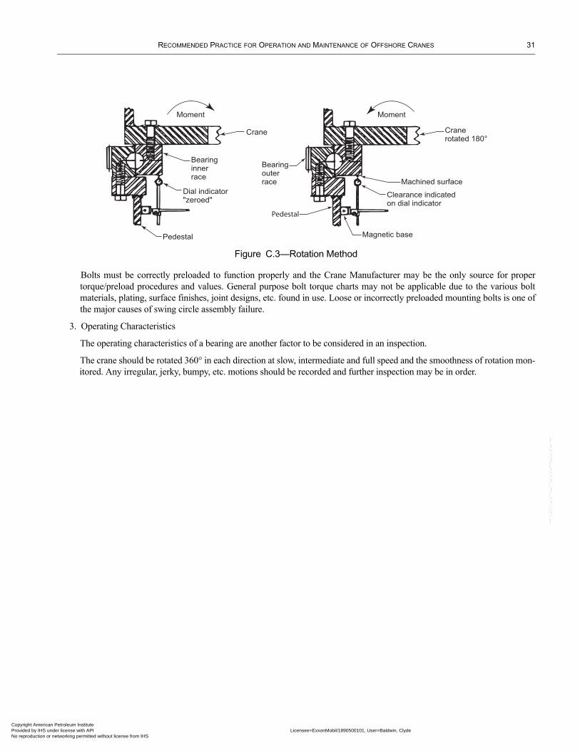
RECOMMENDED PRACTICE FOR OPERATION AND MAINTENANCE OF OFFSHORE CRANES 31
Copyright AmericaProvided by IHS uNo reproduction o
--``,`,`,``,,`,```,,,```,,`,`,`,-`-`,,`,,`,`,,`---
Figure C.3—Rotation Method
Moment Moment
Pedestal
Crane Cranerotated 180°
Bearinginnerrace
Dial indicator "zeroed"
Clearance indicatedon dial indicator
Bearingouterrace
Pedestal
Magnetic base
Machined surface
Bolts must be correctly preloaded to function properly and the Crane Manufacturer may be the only source for proper torque/preload procedures and values. General purpose bolt torque charts may not be applicable due to the various bolt materials, plating, surface finishes, joint designs, etc. found in use. Loose or incorrectly preloaded mounting bolts is one of the major causes of swing circle assembly failure.
3. Operating Characteristics
The operating characteristics of a bearing are another factor to be considered in an inspection.
The crane should be rotated 360° in each direction at slow, intermediate and full speed and the smoothness of rotation mon-itored. Any irregular, jerky, bumpy, etc. motions should be recorded and further inspection may be in order.
n Petroleum Institute nder license with API Licensee=ExxonMobil/1890500101, User=Baldwin, Clyde
Not for Resale, 02/16/2011 06:46:38 MSTr networking permitted without license from IHS

Copyright AmProvided by No reproduc
--``,`,`,``,,`,```,,,```,,`,`,`,-`-`,,`,,`,`,,`---
erican Petroleum Institute IHS under license with API Licensee=ExxonMobil/1890500101, User=Baldwin, Clyde
Not for Resale, 02/16/2011 06:46:38 MSTtion or networking permitted without license from IHS
Copyright AmericaProvided by IHS uNo reproduction o
APPENDIX D—SPRING-SET HOIST BRAKES
Spring-set Hoist Brake Test ProceduresThe following are recommended methods for spring-set brake testing. Consult the Crane Manufacturer for additional information relative to the proper method and desired torque ratings.
1. Apply the torque with a suitable torque wrench at the end of the shaft for hoists with an integral motor and brake.2. For hoist with a band brake or internal load brake detach the motor without disconnecting the non-mechanical lines. Apply torque with a suitable torque wrench at the exposed countershaft end.3. Power the hoist motor in the down direction with the brake applied until the hoist motor is stalled. (Consult the Crane Man-ufacturer for the best applicable test procedure.)
--``,`,`,``,,`,```,,,```,,`,`,`,-`-`,,`,,`,`,,`---
33
n Petroleum Institute nder license with API Licensee=ExxonMobil/1890500101, User=Baldwin, Clyde
Not for Resale, 02/16/2011 06:46:38 MSTr networking permitted without license from IHS

Copyright AmProvided by No reproduc
--``,`,`,``,,`,```,,,```,,`,`,`,-`-`,,`,,`,`,,`---
erican Petroleum Institute IHS under license with API Licensee=ExxonMobil/1890500101, User=Baldwin, Clyde
Not for Resale, 02/16/2011 06:46:38 MSTtion or networking permitted without license from IHS
Copyright AmericaProvided by IHS uNo reproduction o
APPENDIX E—LOAD TESTING
A crane load test is required under the following conditions:
1. New cranes being placed into service.2. Cranes that are being permanently relocated.3. Temporary cranes after each rig-up or relocation.
Crane load testing is not required to determine the fitness of repairs or alterations, provided the repair and replacement procedures outlined in 4.3.3 are followed.
The load applied to the crane during the test should be carefully chosen by the designated Qualified Inspector. Since the test loads are based on the crane rating chart, the Qualified Inspector must be familiar with the applicable load-rating chart. Figure E.1 is a graph of capacity vs. radius for a typical crane. The rating for the crane is always limited by the lowest point of all the curves as shown in Figure E.1. The load-rating chart should show the maximum capacity for each radius. Note the shaded area for the typi-cal crane rigged with two-part line and the transition points A and B. To the left of point A, the rated load is limited by the avail-able hoist line pull and wire rope strength. Between points A and B, the rated load is limited by the over turning moment (OTM); and to the right of point B, the rated load is limited by the boom suspension system. This graph has been greatly simplified for this illustration and the Qualified Inspector should be aware that curves for the boom, gantry, swing bearing, etc., have been omitted for clarity. Since it is obviously impossible to test all of the crane components at the same time, the Qualified Inspector should choose test loads that specifically stress the repaired or altered component. Since the crane’s hoists and ropes will be used to impose the overload on the crane, the Qualified Inspector should choose a test load that is within the capacity of the hoist(s) and rope(s) as normally rigged. The crane should not be rigged with extra parts of line to lift a greater test load at a closer radius. The test load may be imposed on the crane with a lesser load at a greater radius.
Using Figure E.1 as an example, the rated load for a four-part line at 20 ft has the same OTM as a two-part line at 40 ft. To the right of point A, a two-part line is capable of overloading the crane while the auxiliary line cannot overload the crane at any radius. The Qualified Inspector should be aware that line pull on many nonmechanical and electric hoists may be self-limiting. The load test requires only that these hoists when self-limiting lift at least 100% of rated load.
The Qualified Inspector should also take into consideration the maximum and minimum boom angles that are usually employed in material transfer over the side of the unit. Consideration should be given to the maximum parts of line that the crane would rea-sonably be expected to use. For example, a test conducted with a two-part main line may be valid for four-part reeving if the altered component is the boom point sheave shaft. It is therefore the responsibility of the Qualified Inspector to select the load test procedures best suited for the requirements and conditions of each test.
Recommended Load Test Procedures
Date: ________________________________________________________________________________________________
Crane Owner: __________________________________________________________________________________________
Platform or Vessel Name: ________________________________________________________________________________
Crane Manufacturer: ____________________________________________________________________________________
Crane Model: __________________________________________________________________________________________
Crane Serial Number: ___________________________________________________________________________________
Boom Length, Main: ______________________________ Boom Length, Auxiliary: __________________________________
Parts of line, Main Hoist: _____________________________ Auxiliary Hoist: ______________________________________
Crane Owner’s Representative:* ___________________________________________________________________________
Qualified Inspector:* ____________________________________________________________________________________
Inspector’s Company/Agency: ____________________________________________________________________________
--``,`,`,``,,`,```,,,```,,`,`,`,-`-`,,`,,`,`,,`---
35
n Petroleum Institute nder license with API Licensee=ExxonMobil/1890500101, User=Baldwin, Clyde
Not for Resale, 02/16/2011 06:46:38 MSTr networking permitted without license from IHS
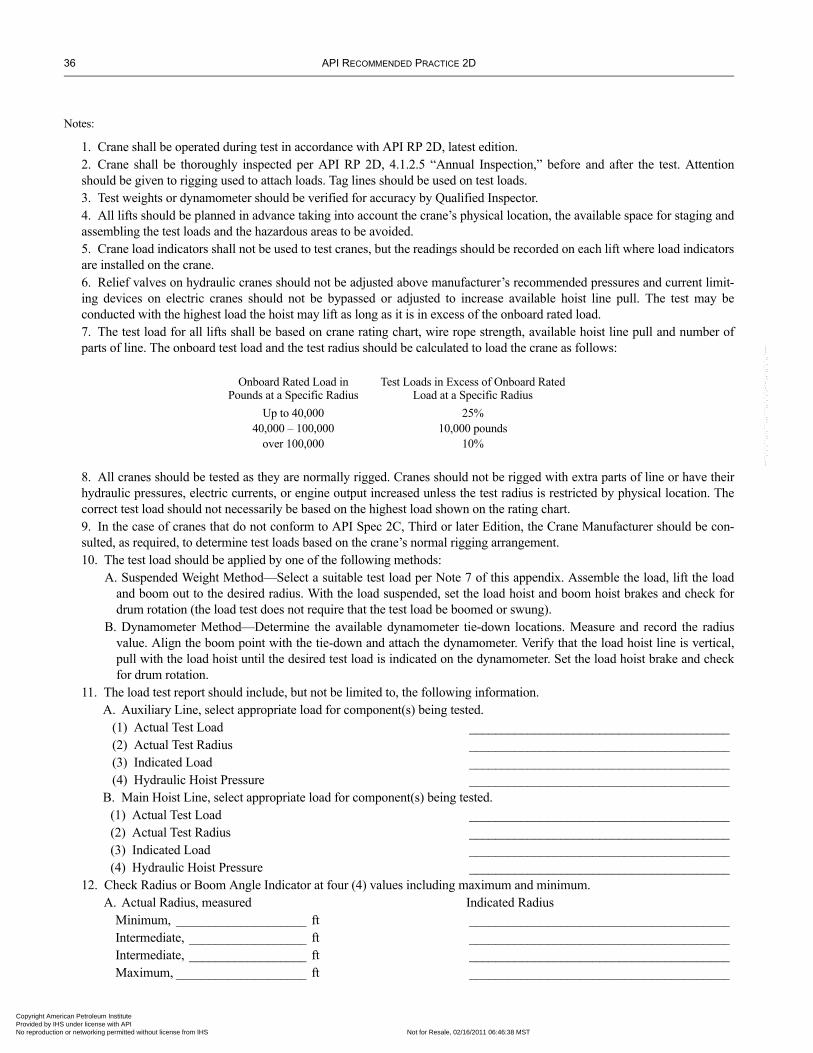
36 API RECOMMENDED PRACTICE 2D
Copyright AmProvided by No reproduc
--``,`,`,``,,`,```,,,```,,`,`,`,-`-`,,`,,`,`,,`---
Notes:
1. Crane shall be operated during test in accordance with API RP 2D, latest edition.2. Crane shall be thoroughly inspected per API RP 2D, 4.1.2.5 “Annual Inspection,” before and after the test. Attention should be given to rigging used to attach loads. Tag lines should be used on test loads.3. Test weights or dynamometer should be verified for accuracy by Qualified Inspector.4. All lifts should be planned in advance taking into account the crane’s physical location, the available space for staging and assembling the test loads and the hazardous areas to be avoided.5. Crane load indicators shall not be used to test cranes, but the readings should be recorded on each lift where load indicators are installed on the crane.6. Relief valves on hydraulic cranes should not be adjusted above manufacturer’s recommended pressures and current limit-ing devices on electric cranes should not be bypassed or adjusted to increase available hoist line pull. The test may be conducted with the highest load the hoist may lift as long as it is in excess of the onboard rated load.7. The test load for all lifts shall be based on crane rating chart, wire rope strength, available hoist line pull and number of parts of line. The onboard test load and the test radius should be calculated to load the crane as follows:
Onboard Rated Load in Pounds at a Specific Radius
Test Loads in Excess of Onboard Rated Load at a Specific Radius
Up to 40,000 25%40,000 – 100,000 10,000 pounds
over 100,000 10%
8. All cranes should be tested as they are normally rigged. Cranes should not be rigged with extra parts of line or have their hydraulic pressures, electric currents, or engine output increased unless the test radius is restricted by physical location. The correct test load should not necessarily be based on the highest load shown on the rating chart.9. In the case of cranes that do not conform to API Spec 2C, Third or later Edition, the Crane Manufacturer should be con-sulted, as required, to determine test loads based on the crane’s normal rigging arrangement.10. The test load should be applied by one of the following methods:
A. Suspended Weight Method—Select a suitable test load per Note 7 of this appendix. Assemble the load, lift the load and boom out to the desired radius. With the load suspended, set the load hoist and boom hoist brakes and check for drum rotation (the load test does not require that the test load be boomed or swung).
B. Dynamometer Method—Determine the available dynamometer tie-down locations. Measure and record the radius value. Align the boom point with the tie-down and attach the dynamometer. Verify that the load hoist line is vertical, pull with the load hoist until the desired test load is indicated on the dynamometer. Set the load hoist brake and check for drum rotation.
11. The load test report should include, but not be limited to, the following information.A. Auxiliary Line, select appropriate load for component(s) being tested.
(1) Actual Test Load ________________________________________(2) Actual Test Radius ________________________________________(3) Indicated Load ________________________________________(4) Hydraulic Hoist Pressure ________________________________________
B. Main Hoist Line, select appropriate load for component(s) being tested.(1) Actual Test Load ________________________________________(2) Actual Test Radius ________________________________________(3) Indicated Load ________________________________________(4) Hydraulic Hoist Pressure ________________________________________
12. Check Radius or Boom Angle Indicator at four (4) values including maximum and minimum.A. Actual Radius, measured Indicated Radius
Minimum, ____________________ ft ________________________________________Intermediate, __________________ ft ________________________________________Intermediate, __________________ ft ________________________________________Maximum, ____________________ ft ________________________________________
erican Petroleum Institute IHS under license with API Licensee=ExxonMobil/1890500101, User=Baldwin, Clyde
Not for Resale, 02/16/2011 06:46:38 MSTtion or networking permitted without license from IHS
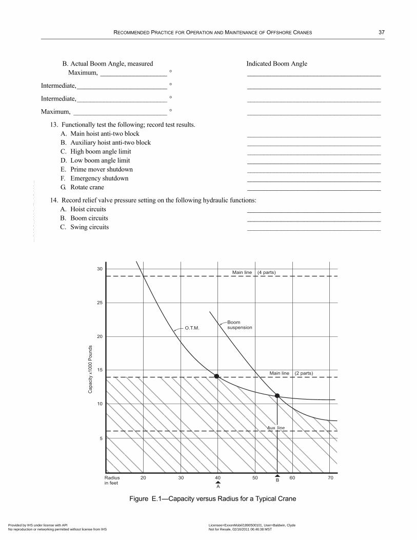
RECOMMENDED PRACTICE FOR OPERATION AND MAINTENANCE OF OFFSHORE CRANES 37
Copyright AmericaProvided by IHS uNo reproduction o
--``,`,`,``,,`,```,,,```,,`,`,`,-`-`,,`,,`,`,,`---
B. Actual Boom Angle, measured Indicated Boom AngleMaximum, ____________________ ° ________________________________________
Intermediate,___________________________ ° ________________________________________
Intermediate,___________________________ ° ________________________________________
Maximum, ____________________________ ° ________________________________________
13. Functionally test the following; record test results.A. Main hoist anti-two block ________________________________________B. Auxiliary hoist anti-two block ________________________________________C. High boom angle limit ________________________________________D. Low boom angle limit ________________________________________E. Prime mover shutdown ________________________________________F. Emergency shutdown ________________________________________G. Rotate crane ________________________________________
14. Record relief valve pressure setting on the following hydraulic functions:A. Hoist circuits ________________________________________B. Boom circuits ________________________________________C. Swing circuits ________________________________________
Figure E.1—Capacity versus Radius for a Typical Crane
30
25
20
15
10
5
Radiusin feet
20
Capacity x
1000 P
ounds
30 40 50 60 70
Main line (4 parts)
Main line (2 parts)
O.T.M.
Boomsuspension
A
B
Aux line
n Petroleum Institute nder license with API Licensee=ExxonMobil/1890500101, User=Baldwin, Clyde
Not for Resale, 02/16/2011 06:46:38 MSTr networking permitted without license from IHS

Copyright AmProvided by No reproduc
erican Petroleum Institute IHS under license with API Licensee=ExxonMobil/1890500101, User=Baldwin, Clyde
Not for Resale, 02/16/2011 06:46:38 MSTtion or networking permitted without license from IHS
--``,`,`,``,,`,```,,,```,,`,`,`,-`-`,,`,,`,`,,`---
Copyright AmericaProvided by IHS uNo reproduction o
--``,`,`,``,,`,```,,,```,,`,`,`,-`-`,,`,,`,`,,`---
APPENDIX F—MAINTENANCE
F.4.3.2 Maintenance Procedure
a. The following additional precautions, where applicable, should be taken, before adjustments, repairs and maintenance are started on a crane.
1. Boom shall be lowered to the deck or boom rest or otherwise secured against dropping and swinging.2. Blocks shall be lowered to the deck or otherwise secured against dropping and swinging.3. All controls shall be in the off or neutral position.
b. Adjustments should include the following:1. All operating mechanisms and control systems.2. Limit devices.3. Swing circle assembly.4. Prime mover.5. Non-mechanical System—Appropriate out of service signs should be placed at the control station and/or prime mover by a Qualified Crane Operator or Inspector. 6. Corrective action should be taken by the Crane Owner.7. After adjustments, repairs and maintenance have been completed, the crane should not be put in-service until all guards have been reinstalled, limit devices reactivated and maintenance equipment removed.
F.4.3.3 Repairs and Replacements
a. Booms which are being assembled or disassembled on the deck, with or without support of the boom harness, shall be securely blocked to prevent dropping of the boom and/or boom sections.b. No welding repairs shall be made to critical components, such as booms and swing circle assemblies, without specific repair procedures and recommendations from the original Crane Manufacturer, or other qualified source (such as an API-licensed 2C Crane Manufacturer, Authorized Surveyor, or an engineer experienced in the design of the crane, as determined by the Crane Owner).
39
n Petroleum Institute nder license with API Licensee=ExxonMobil/1890500101, User=Baldwin, Clyde
Not for Resale, 02/16/2011 06:46:38 MSTr networking permitted without license from IHS

Copyright AmProvided by No reproduc
erican Petroleum Institute IHS under license with API Licensee=ExxonMobil/1890500101, User=Baldwin, Clyde
Not for Resale, 02/16/2011 06:46:38 MSTtion or networking permitted without license from IHS
--``,`,`,``,,`,```,,,```,,`,`,`,-`-`,,`,,`,`,,`---
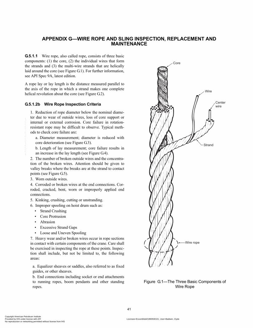
Copyright AmericaProvided by IHS uNo reproduction o
APPENDIX G—WIRE ROPE AND SLING INSPECTION, REPLACEMENT AND MAINTENANCE
G.5.1.1 Wire rope, also called rope, consists of three basic components: (1) the core, (2) the individual wires that form the strands and (3) the multi-wire strands that are helically laid around the core (see Figure G.1). For further information, see API Spec 9A, latest edition.
A rope lay or lay length is the distance measured parallel to the axis of the rope in which a strand makes one complete helical revolution about the core (see Figure G.2).
G.5.1.2b Wire Rope Inspection Criteria
1. Reduction of rope diameter below the nominal diame-ter due to wear of outside wires, loss of core support or internal or external corrosion. Core failure in rotation-resistant rope may be difficult to observe. Typical meth-ods to check core failure are:
a. Diameter measurement; diameter is reduced with core deterioration (see Figure G.3).b. Length of lay measurement; core failure results in an increase in the lay length (see Figure G.4).
2. The number of broken outside wires and the concentra-tion of the broken wires. Attention should be given to valley breaks where the breaks are at the strand to contact points (see Figure G.5).3. Worn outside wires.4. Corroded or broken wires at the end connections. Cor-roded, cracked, bent, worn or improperly applied end connections.5. Kinking, crushing, cutting or unstranding.6. Improper spooling on hoist drum such as:
• Strand Crushing• Core Protrusion• Abrasion• Excessive Strand Gaps• Loose and Uneven Spooling
Figure G.1—The Three Basic Components of Wire Rope
Core
Wire
Centerwire
Strand
Wire rope
7. Heavy wear and/or broken wires occur in rope sections in contact with certain components of the crane. Care shall be exercised in inspecting the rope at these points. Inspec-tion shall include, but not be limited to, the following areas:
a. Equalizer sheaves or saddles, also referred to as fixed guides, or other sheaves.b. End connections including socket or end attachments to running ropes, boom pendants and other standing ropes.
--``,`,`,``,,`,```,,,```,,`,`,`,-`-`,,`,,`,`,,`---
41
n Petroleum Institute nder license with API Licensee=ExxonMobil/1890500101, User=Baldwin, Clyde
Not for Resale, 02/16/2011 06:46:38 MSTr networking permitted without license from IHS
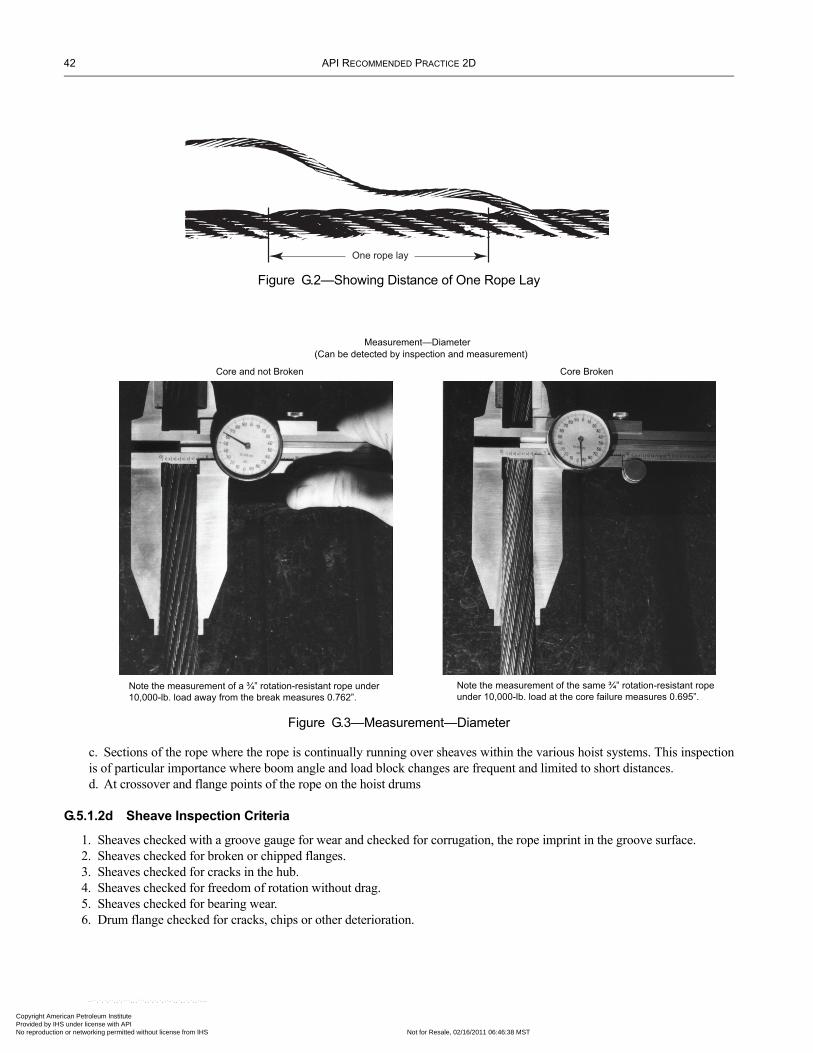
42 API RECOMMENDED PRACTICE 2D
Copyright AmProvided by No reproduc
Figure G.2—Showing Distance of One Rope Lay
One rope lay
Figure G.3—Measurement—Diameter
Measurement—Diameter
(Can be detected by inspection and measurement)
Core and not Broken Core Broken
Note the measurement of a ¾” rotation-resistant rope under
10,000-lb. load away from the break measures 0.762”.
Note the measurement of the same ¾” rotation-resistant rope
under 10,000-lb. load at the core failure measures 0.695”.
c. Sections of the rope where the rope is continually running over sheaves within the various hoist systems. This inspection is of particular importance where boom angle and load block changes are frequent and limited to short distances. d. At crossover and flange points of the rope on the hoist drums
G.5.1.2d Sheave Inspection Criteria
1. Sheaves checked with a groove gauge for wear and checked for corrugation, the rope imprint in the groove surface.2. Sheaves checked for broken or chipped flanges.3. Sheaves checked for cracks in the hub.4. Sheaves checked for freedom of rotation without drag.5. Sheaves checked for bearing wear.6. Drum flange checked for cracks, chips or other deterioration.
erican Petroleum Institute IHS under license with API Licensee=ExxonMobil/1890500101, User=Baldwin, Clyde
Not for Resale, 02/16/2011 06:46:38 MSTtion or networking permitted without license from IHS
--``,`,`,``,,`,```,,,```,,`,`,`,-`-`,,`,,`,`,,`---
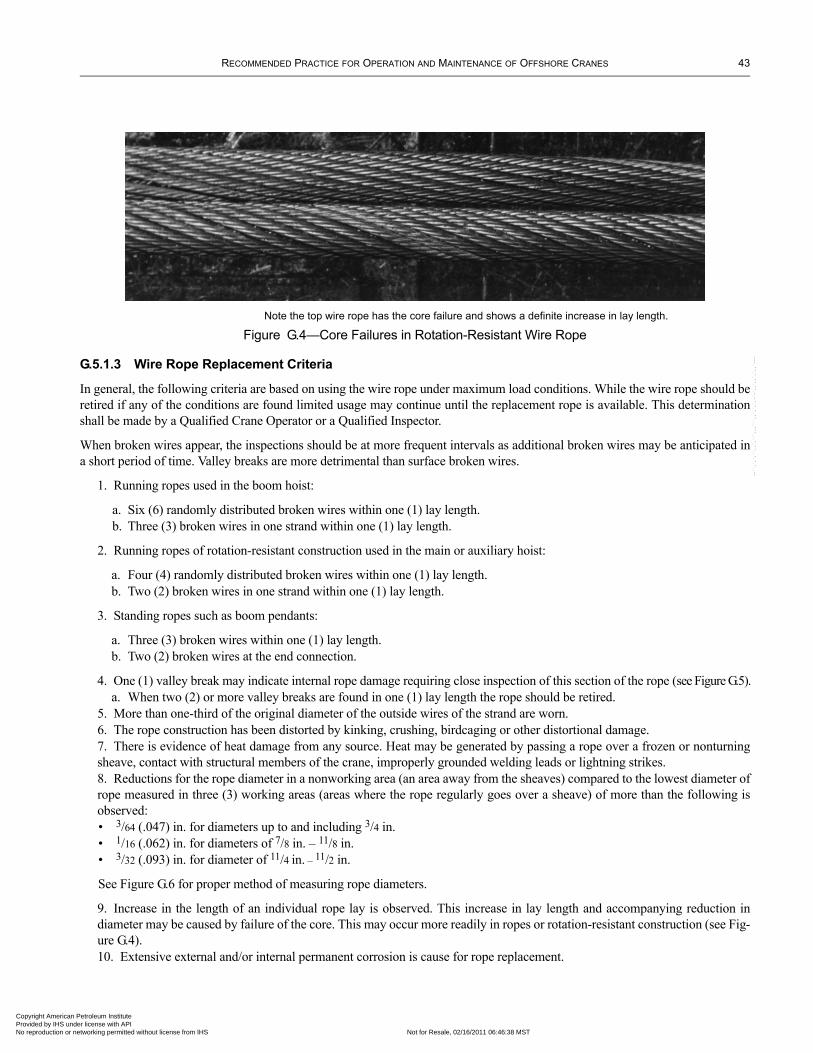
RECOMMENDED PRACTICE FOR OPERATION AND MAINTENANCE OF OFFSHORE CRANES 43
Copyright AmericaProvided by IHS uNo reproduction o
Figure G.4—Core Failures in Rotation-Resistant Wire RopeNote the top wire rope has the core failure and shows a definite increase in lay length.
G.5.1.3 Wire Rope Replacement Criteria
In general, the following criteria are based on using the wire rope under maximum load conditions. While the wire rope should be retired if any of the conditions are found limited usage may continue until the replacement rope is available. This determination shall be made by a Qualified Crane Operator or a Qualified Inspector.
When broken wires appear, the inspections should be at more frequent intervals as additional broken wires may be anticipated in a short period of time. Valley breaks are more detrimental than surface broken wires.
1. Running ropes used in the boom hoist:
a. Six (6) randomly distributed broken wires within one (1) lay length.b. Three (3) broken wires in one strand within one (1) lay length.
2. Running ropes of rotation-resistant construction used in the main or auxiliary hoist:
a. Four (4) randomly distributed broken wires within one (1) lay length.b. Two (2) broken wires in one strand within one (1) lay length.
3. Standing ropes such as boom pendants:
a. Three (3) broken wires within one (1) lay length.b. Two (2) broken wires at the end connection.
4. One (1) valley break may indicate internal rope damage requiring close inspection of this section of the rope (see Figure G.5).a. When two (2) or more valley breaks are found in one (1) lay length the rope should be retired.
5. More than one-third of the original diameter of the outside wires of the strand are worn.6. The rope construction has been distorted by kinking, crushing, birdcaging or other distortional damage.7. There is evidence of heat damage from any source. Heat may be generated by passing a rope over a frozen or nonturning sheave, contact with structural members of the crane, improperly grounded welding leads or lightning strikes.8. Reductions for the rope diameter in a nonworking area (an area away from the sheaves) compared to the lowest diameter of rope measured in three (3) working areas (areas where the rope regularly goes over a sheave) of more than the following is observed:• 3/64 (.047) in. for diameters up to and including 3/4 in.• 1/16 (.062) in. for diameters of 7/8 in. – 11/8 in.• 3/32 (.093) in. for diameter of 11/4 in. – 11/2 in.
See Figure G.6 for proper method of measuring rope diameters.
9. Increase in the length of an individual rope lay is observed. This increase in lay length and accompanying reduction in diameter may be caused by failure of the core. This may occur more readily in ropes or rotation-resistant construction (see Fig-ure G.4).10. Extensive external and/or internal permanent corrosion is cause for rope replacement.
--``,`,`,``,,`,```,,,```,,`,`,`,-`-`,,`,,`,`,,`---
n Petroleum Institute nder license with API Licensee=ExxonMobil/1890500101, User=Baldwin, Clyde
Not for Resale, 02/16/2011 06:46:38 MSTr networking permitted without license from IHS
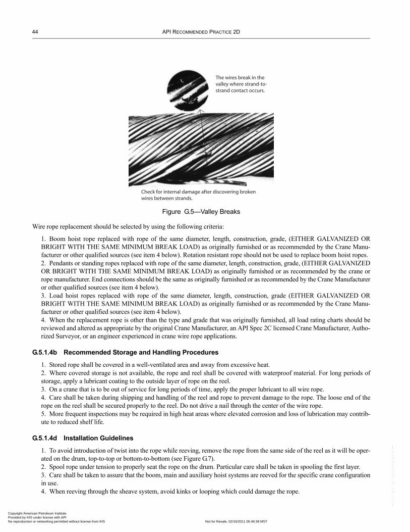
44 API RECOMMENDED PRACTICE 2D
Copyright AmProvided by No reproduc
,`,`,``,,`,```,,,```,,`,`,`,-`-`,,`,,`,`,,`---
Figure G.5—Valley Breaks
Check for internal damage after discovering brokenwires between strands.
The wires break in the valley where strand-to-strand contact occurs.
Wire rope replacement should be selected by using the following criteria:
1. Boom hoist rope replaced with rope of the same diameter, length, construction, grade, (EITHER GALVANIZED OR BRIGHT WITH THE SAME MINIMUM BREAK LOAD) as originally furnished or as recommended by the Crane Manu-facturer or other qualified sources (see item 4 below). Rotation resistant rope should not be used to replace boom hoist ropes.2. Pendants or standing ropes replaced with rope of the same diameter, length, construction, grade, (EITHER GALVANIZED OR BRIGHT WITH THE SAME MINIMUM BREAK LOAD) as originally furnished or as recommended by the crane or rope manufacturer. End connections should be the same as originally furnished or as recommended by the Crane Manufacturer or other qualified sources (see item 4 below).3. Load hoist ropes replaced with rope of the same diameter, length, construction, grade (EITHER GALVANIZED OR BRIGHT WITH THE SAME MINIMUM BREAK LOAD) as originally furnished or as recommended by the Crane Manu-facturer or other qualified sources (see item 4 below).4. When the replacement rope is other than the type and grade that was originally furnished, all load rating charts should be reviewed and altered as appropriate by the original Crane Manufacturer, an API Spec 2C licensed Crane Manufacturer, Autho-rized Surveyor, or an engineer experienced in crane wire rope applications.
G.5.1.4b Recommended Storage and Handling Procedures
1. Stored rope shall be covered in a well-ventilated area and away from excessive heat.2. Where covered storage is not available, the rope and reel shall be covered with waterproof material. For long periods of storage, apply a lubricant coating to the outside layer of rope on the reel.3. On a crane that is to be out of service for long periods of time, apply the proper lubricant to all wire rope.4. Care shall be taken during shipping and handling of the reel and rope to prevent damage to the rope. The loose end of the rope on the reel shall be secured properly to the reel. Do not drive a nail through the center of the wire rope.5. More frequent inspections may be required in high heat areas where elevated corrosion and loss of lubrication may contrib-ute to reduced shelf life.
G.5.1.4d Installation Guidelines
1. To avoid introduction of twist into the rope while reeving, remove the rope from the same side of the reel as it will be oper-ated on the drum, top-to-top or bottom-to-bottom (see Figure G.7).2. Spool rope under tension to properly seat the rope on the drum. Particular care shall be taken in spooling the first layer.3. Care shall be taken to assure that the boom, main and auxiliary hoist systems are reeved for the specific crane configuration in use.4. When reeving through the sheave system, avoid kinks or looping which could damage the rope.
erican Petroleum Institute IHS under license with API Licensee=ExxonMobil/1890500101, User=Baldwin, Clyde
Not for Resale, 02/16/2011 06:46:38 MSTtion or networking permitted without license from IHS
--``
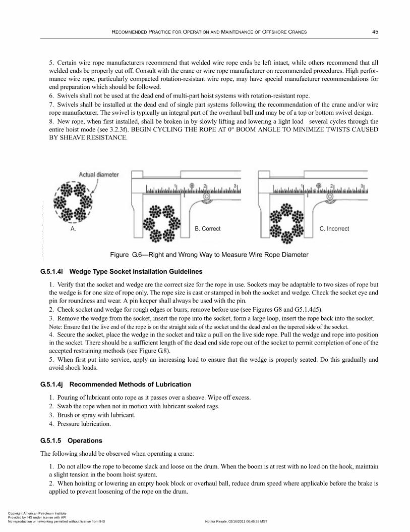
RECOMMENDED PRACTICE FOR OPERATION AND MAINTENANCE OF OFFSHORE CRANES 45
Copyright AmericaProvided by IHS uNo reproduction o
5. Certain wire rope manufacturers recommend that welded wire rope ends be left intact, while others recommend that all welded ends be properly cut off. Consult with the crane or wire rope manufacturer on recommended procedures. High perfor-mance wire rope, particularly compacted rotation-resistant wire rope, may have special manufacturer recommendations for end preparation which should be followed. 6. Swivels shall not be used at the dead end of multi-part hoist systems with rotation-resistant rope.7. Swivels shall be installed at the dead end of single part systems following the recommendation of the crane and/or wire rope manufacturer. The swivel is typically an integral part of the overhaul ball and may be of a top or bottom swivel design.8. New rope, when first installed, shall be broken in by slowly lifting and lowering a light load several cycles through the entire hoist mode (see 3.2.3f). BEGIN CYCLING THE ROPE AT 0° BOOM ANGLE TO MINIMIZE TWISTS CAUSED BY SHEAVE RESISTANCE.
Figure G.6—Right and Wrong Way to Measure Wire Rope Diameter
A. B. Correct C. Incorrect
G.5.1.4i Wedge Type Socket Installation Guidelines
1. Verify that the socket and wedge are the correct size for the rope in use. Sockets may be adaptable to two sizes of rope but the wedge is for one size of rope only. The rope size is cast or stamped in boh the socket and wedge. Check the socket eye and pin for roundness and wear. A pin keeper shall always be used with the pin.2. Check socket and wedge for rough edges or burrs; remove before use (see Figures G8 and G5.1.4d5). 3. Remove the wedge from the socket, insert the rope into the socket, form a large loop, insert the rope back into the socket. Note: Ensure that the live end of the rope is on the straight side of the socket and the dead end on the tapered side of the socket.4. Secure the socket, place the wedge in the socket and take a pull on the live side rope. Pull the wedge and rope into position in the socket. There should be a sufficient length of the dead end side rope out of the socket to permit completion of one of the accepted restraining methods (see Figure G.8).5. When first put into service, apply an increasing load to ensure that the wedge is properly seated. Do this gradually and avoid shock loads.
G.5.1.4j Recommended Methods of Lubrication
1. Pouring of lubricant onto rope as it passes over a sheave. Wipe off excess.2. Swab the rope when not in motion with lubricant soaked rags.3. Brush or spray with lubricant.4. Pressure lubrication.
G.5.1.5 Operations
The following should be observed when operating a crane:
1. Do not allow the rope to become slack and loose on the drum. When the boom is at rest with no load on the hook, maintain a slight tension in the boom hoist system.2. When hoisting or lowering an empty hook block or overhaul ball, reduce drum speed where applicable before the brake is applied to prevent loosening of the rope on the drum.
--``,`,`,``,,`,```,,,```,,`,`,`,-`-`,,`,,`,`,,`---
n Petroleum Institute nder license with API Licensee=ExxonMobil/1890500101, User=Baldwin, Clyde
Not for Resale, 02/16/2011 06:46:38 MSTr networking permitted without license from IHS
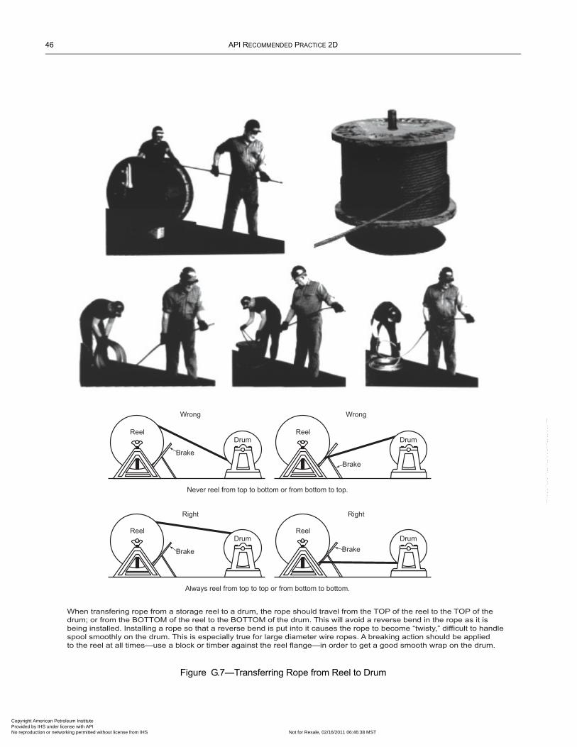
46 API RECOMMENDED PRACTICE 2D
Copyright AmProvided by No reproduc
--``,`,`,``,,`,```,,,```,,`,`,`,-`-`,,`,,`,`,,`---
Figure G.7—Transferring Rope from Reel to Drum
ReelDrum
Brake
Wrong
ReelDrum
Brake
Wrong
Never reel from top to bottom or from bottom to top.
ReelDrum
Brake
Right
ReelDrum
Brake
Right
Always reel from top to top or from bottom to bottom.
When transfering rope from a storage reel to a drum, the rope should travel from the TOP of the reel to the TOP of the
drum; or from the BOTTOM of the reel to the BOTTOM of the drum. This will avoid a reverse bend in the rope as it is
being installed. Installing a rope so that a reverse bend is put into it causes the rope to become “twisty,” difficult to handle
spool smoothly on the drum. This is especially true for large diameter wire ropes. A breaking action should be applied
to the reel at all times—use a block or timber against the reel flange—in order to get a good smooth wrap on the drum.
erican Petroleum Institute IHS under license with API Licensee=ExxonMobil/1890500101, User=Baldwin, Clyde
Not for Resale, 02/16/2011 06:46:38 MSTtion or networking permitted without license from IHS
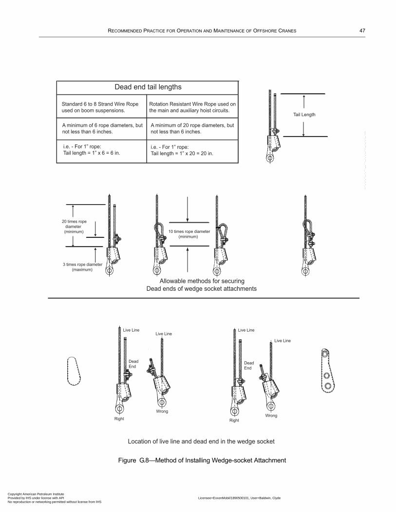
RECOMMENDED PRACTICE FOR OPERATION AND MAINTENANCE OF OFFSHORE CRANES 47
Copyright AmericaProvided by IHS uNo reproduction o
Figure G.8—Method of Installing Wedge-socket Attachment
Dead end tail lengths
Standard 6 to 8 Strand Wire Rope
used on boom suspensions.
A minimum of 6 rope diameters, but
not less than 6 inches.
i.e. - For 1” rope:
Tail length = 1” x 6 = 6 in.
Rotation Resistant Wire Rope used on
the main and auxiliary hoist circuits.
i.e. - For 1” rope:
Tail length = 1” x 20 = 20 in.
Tail Length
10 times rope diameter
(minimum)
3 times rope diameter
(maximum)
20 times rope
diameter
(minimum)
Allowable methods for securing
Dead ends of wedge socket attachments
Live Line
Wrong
Live Line
Dead
End
Live Line
Right
Wrong
Live Line
Dead
End
Right
Location of live line and dead end in the wedge socket
A minimum of 20 rope diameters, but
not less than 6 inches.
--``,`,`,``,,`,```,,,```,,`,`,`,-`-`,,`,,`,`,,`---
n Petroleum Institute nder license with API Licensee=ExxonMobil/1890500101, User=Baldwin, Clyde
Not for Resale, 02/16/2011 06:46:38 MSTr networking permitted without license from IHS
48 API RECOMMENDED PRACTICE 2D
Copyright AmProvided by No reproduc
3. When a rope is found to be loose on the drum, re-spool the rope under tension as soon as practical while performing a visual inspection of the rope. During all inspections other than the Pre-use Inspection, re-spool the drum under tension where required and practical.
G.5.2 SLINGS
The types of slings typically used are:
1. Wire rope slings.2. Synthetic webbing slings.3. Alloy steel chain slings.4. Synthetic roundslings.
G.5.2.1 Use of Slings
The guidelines below should be followed when using slings:
1. Suitable protection shall be provided between the sling and all sharp surfaces of the load to be lifted.2. Proper storage shall be provided for slings while not in use.3. Slings shall never be choked in the splice.4. Sharp kinks or knots shall not be permitted in wire rope slings.5. Loads shall not be lifted with one leg of a multi-leg bridle sling until the unused legs are secured.6. Any angle other than vertical at which a sling is rigged increases the loading on the sling.7. Whenever a sling is found to be deficient, the eyes should be cut, or other end attachments or fittings removed to prevent further use, and the sling body discarded.8. A sling eye should never be used over a hook or pin with a body diameter larger than the natural width of the eye. Never force an eye on a hook. The eye should always be used on a hook or pin with at least the diameter of the rope.9. A sling shall be visually inspected before use to determine if it is capable of safely making the intended lift.10. Rated loads of a sling are different for each of the three basic methods of rigging (vertical, choker, basket, etc.) and the rated loads of a sling are different for each of the methods of rigging based upon the angle of hitch, on construction of the wire rope, web material and width, etc. These rated loads are available from the manufacturer. These rated loads should be indi-cated on the heavy duty tags attached to each type of sling at the time it is fabricated.
G.5.2.2 Guidelines for Fabrication and Lifting Procedures
Wire rope slings should generally not be field fabricated. If circumstances require field fabrication proper equipment should be available and Qualified Inspectors should supervise or perform this function using accepted standard practices. Zinc or resin poured sockets shall be fabricated in accordance with API RP 9B (latest edition).
1. No single-leg hitch shall be used on slings with a load that cannot be controlled. Always rig the sling and load so as not to allow the load or lifting device to rotate and unlay the sling rope. Rotation or twisting of the load may cause excessive stress on the attachment connection and reduce the sling’s capacity or pull out.2. Slings used in choker configurations have a rated capacity of 70% of vertical load limit of a single leg sling if the choke angle is 120° or greater (see Figure G.9).3. For bridle slings and basket hitches where both legs are not vertical use of the following equation for computation of the sling arrangement rated capacity. Rated Capacity = Single-leg capacity (see Table G.1) times the number of legs times the cosine of angle A. 4. Slings shall not be made using wire rope clips.
G.5.2.3 Sling Replacement
Reasons for replacing slings are as follows:
1. In single part slings constructed of 6 × 19 class and 6 × 37 class wire rope in single-part slings, ten (10) randomly distrib-uted broken wires in one lay length or five (5) broken wires in one strand in one lay length. For other constructions, refer to the Wire Rope Sling Users Manual and/or ASME B30.9.
erican Petroleum Institute IHS under license with API Licensee=ExxonMobil/1890500101, User=Baldwin, Clyde
Not for Resale, 02/16/2011 06:46:38 MSTtion or networking permitted without license from IHS
--``,`,`,``,,`,```,,,```,,`,`,`,-`-`,,`,,`,`,,`---
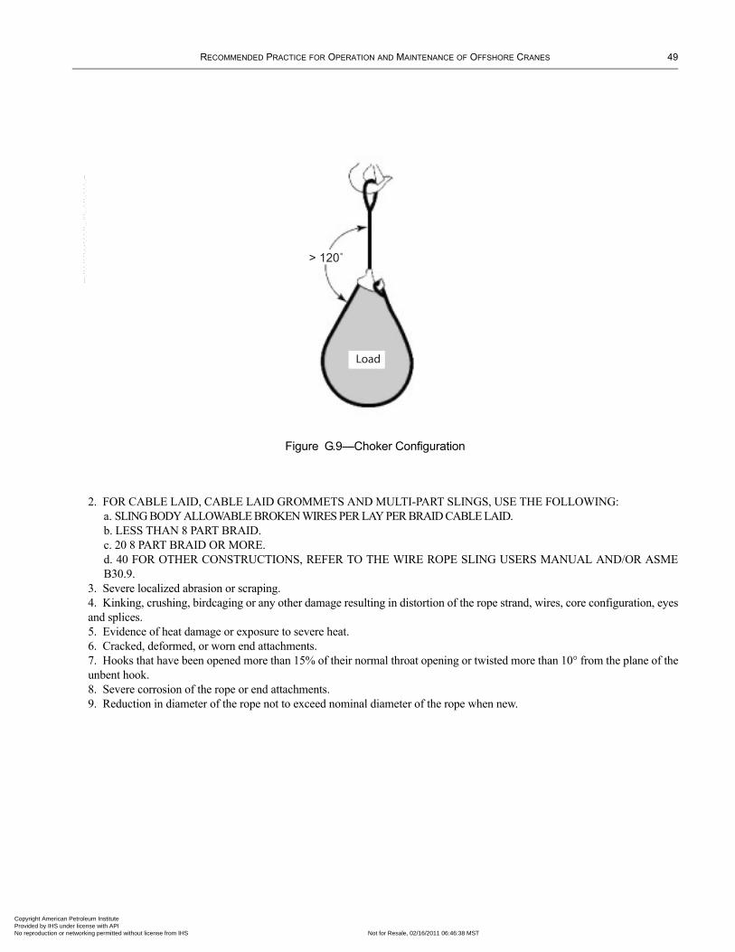
RECOMMENDED PRACTICE FOR OPERATION AND MAINTENANCE OF OFFSHORE CRANES 49
Copyright AmericaProvided by IHS uNo reproduction o
Figure G.9—Choker Configuration
Load
> 120˚
2. FOR CABLE LAID, CABLE LAID GROMMETS AND MULTI-PART SLINGS, USE THE FOLLOWING: a. SLING BODY ALLOWABLE BROKEN WIRES PER LAY PER BRAID CABLE LAID. b. LESS THAN 8 PART BRAID. c. 20 8 PART BRAID OR MORE. d. 40 FOR OTHER CONSTRUCTIONS, REFER TO THE WIRE ROPE SLING USERS MANUAL AND/OR ASME B30.9.
3. Severe localized abrasion or scraping.4. Kinking, crushing, birdcaging or any other damage resulting in distortion of the rope strand, wires, core configuration, eyes and splices.5. Evidence of heat damage or exposure to severe heat.6. Cracked, deformed, or worn end attachments.7. Hooks that have been opened more than 15% of their normal throat opening or twisted more than 10° from the plane of the unbent hook.8. Severe corrosion of the rope or end attachments.9. Reduction in diameter of the rope not to exceed nominal diameter of the rope when new.
--``,`,`,``,,`,```,,,```,,`,`,`,-`-`,,`,,`,`,,`---
n Petroleum Institute nder license with API Licensee=ExxonMobil/1890500101, User=Baldwin, Clyde
Not for Resale, 02/16/2011 06:46:38 MSTr networking permitted without license from IHS
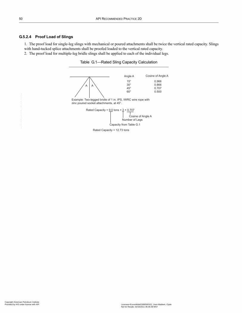
50 API RECOMMENDED PRACTICE 2D
Copyright AmProvided by No reproduc
G.5.2.4 Proof Load of Slings
1. The proof load for single-leg slings with mechanical or poured attachments shall be twice the vertical rated capacity. Slings with hand-tucked splice attachments shall be proofed loaded to the vertical rated capacity.2. The proof load for multiple-leg bridle slings shall be applied to each of the individual legs.
Table G.1—Rated Sling Capacity Calculation
A A
Example: Two-legged bridle of 1 in. IPS, IWRC wire rope with
zinc poured socket attachments, at 45°.
Angle A
15°
30°
45°
60°
Cosine of Angle A
0.966
0.866
0.707
0.500
Rated Capacity = 9.0 tons × 2 × 0.707
Cosine of Angle A
Number of Legs
Capacity from Table G.1
Rated Capacity = 12.73 tons
--``,`,`,``,,`,```,,,```,,`,`,`,-`-`,,`,,`,`,,`---
erican Petroleum Institute IHS under license with API Licensee=ExxonMobil/1890500101, User=Baldwin, Clyde
Not for Resale, 02/16/2011 06:46:38 MSTtion or networking permitted without license from IHS
Copyright AmericaProvided by IHS uNo reproduction o
APPENDIX H—REFERENCES
H.1 Referenced DocumentsAPI
Spec 2C Offshore CranesSpec 9A Specification for Wire RopeRP 9B Application, Care and Use of Wire Rope for Oil Field Service
ASME1 B30.5 Mobile and Locomotive Type Cranes
ASTM2 A 906/A 906M Standard Specification for Forged Grade 80 and Grade 100 Alloy Steel Chain Slings for Overhead Lifting
Federal Specification3
RR-W-410 Wire Rope and Strand
WSTDA4
Recommended Standard Specifications for Synthetic Polyester RoundslingsRecommended Standard Specifications for Synthetic Web Slings
WRTB5
Wire Rope Sling Users Manual
H.2 Related Documents and AssociationsThe following are other standards and specifications not directly for slings, but related to lifting.
ASMEB30.9 SlingsB30.10 HooksB30.20 Below-the-Hook Lifting DevicesB30.26 Rigging Hardware (Under Development)
WRTBWire Rope Users Manual
Other Associations that are related to the Sling Industry:
Associated Wire Rope Fabricators (AWRF)P.O. Box 20126Lehigh Valley, PA 18002-0126
National Association of Chain Manufacturers (NACM)P.O. Box 22681Lehigh Valley, PA 18002-2681
Association of Crane and Rigging Professionals (ACRP)P.O. Box 61589Vancouver, WA 98666-1589
1American Society of Mechanical Engineers, 345 East 47th Street, New York, New York 10017-2392, www.asme.org.2American Society for Testing Materials, P.O. Box C700, West Conshohocken, Pennsylvania 19428-2959, www.astm.org.3U.S. Government Printing Office, 732 North Capitol Street NW, Washington D.C. 20401, www.gpo.org.4Web Sling & Tie Down Association, Inc., 5024-R Campbell Boulevard, Baltimore, Maryland 21236-5974, www.wstda.com.5Wire Rope Technical Board, 801 North Fairfax Street, Suite 211, Alexandria, Virginia 22314-1757, www.domesticwirerope/wrtb/.
51
n Petroleum Institute nder license with API Licensee=ExxonMobil/1890500101, User=Baldwin, Clyde
Not for Resale, 02/16/2011 06:46:38 MSTr networking permitted without license from IHS
--``,`,`,``,,`,```,,,```,,`,`,`,-`-`,,`,,`,`,,`---

Copyright AmericaProvided by IHS uNo reproduction o
--``,`,`,``,,`,```,,,```,,`,`,`,-`-`,,`,,`,`,,`---
n Petroleum Institute nder license with API Licensee=ExxonMobil/1890500101, User=Baldwin, Clyde
Not for Resale, 02/16/2011 06:46:38 MSTr networking permitted without license from IHS

Copyright AmericaProvided by IHS uNo reproduction o
APPENDIX I—TEMPORARY CRANE INSTALLATION GUIDELINES
I.1 Temporary CranesPlanning the Installation Planning of a temporary crane installation will require that a qualified person, an API licensed 2C Crane Manufacturer, Autho-rized Surveyor or an Engineer experienced in the design of the crane be utilized, as determined by the owner. The Crane Owner shall assure that calculations conform to API Spec 2C and are recorded and documented. The qualified person shall assure the adequate review of the following:
• platform design and condition; • selected temporary crane; • planned crane placement on the platform; • crane base beams and sub-base beams, and tie down design, meet the safe working loads for the crane being installed; • critical components meet API Spec 2C criteria.
The tie down design may be welded or clamped design. Should any of these critical components limit the load of the crane, then this shall be reflected in the crane’s load chart designed specifically for this proposed location per Spec 2C. The load chart shall be applicable through the full rotation of the crane.If any one lift of the temporary crane package is equal to or greater than 80% of the rated capacity of the platform crane at the anticipated radius, an Annual Inspection with pull test shall be performed within 30 days prior to the lift.
Installing the Temporary Cranes The platform beams and the temporary crane beams shall be inspected for laminations to insure the integrity of the tie down welds. Welding and tie down procedures shall be designed and approved by a qualified person. All welding procedures for joining of structural load bearing or load transfer members and the performance of welders employing these procedures shall be qualified in accordance with a recognized standard such as AWS D1.1.
Testing and Inspecting the Installation Load tests shall be performed by a Qualified Inspector in accordance with this standard (see Appendix E). An Annual Inspection shall be performed before and after the load test. The tie down welds shall be inspected by non destructive testing by a qualified person before and after load testing. Examples of this type of testing are Ultrasonic Testing, Magnetic Particle, Dye Penetrant or Radiographic Examination.
--``,`,`,``,,`,```,,,```,,`,`,`,-`-`,,`,,`,`,,`---
53n Petroleum Institute nder license with API Licensee=ExxonMobil/1890500101, User=Baldwin, Clyde
Not for Resale, 02/16/2011 06:46:38 MSTr networking permitted without license from IHS

Copyright American Petroleum Institute Provided by IHS under license with API Licensee=ExxonMobil/1890500101, User=Baldwin, Clyde
Not for Resale, 02/16/2011 06:46:38 MSTNo reproduction or networking permitted without license from IHS
--``,`,`,``,,`,```,,,```,,`,`,`,-`-`,,`,,`,`,,`---

05/07
Copyright American Petroleum Institute Provided by IHS under license with API Licensee=ExxonMobil/1890500101, User=Baldwin, Clyde
Not for Resale, 02/16/2011 06:46:38 MSTNo reproduction or networking permitted without license from IHS
--``,`,`,``,,`,```,,,```,,`,`,`,-`-`,,`,,`,`,,`---

Product No. G02D06
Additional copies are available through IHSPhone Orders: 1-800-854-7179 (Toll-free in the U.S. and Canada)
303-397-7956 (Local and International)Fax Orders: 303-397-2740Online Orders: global.ihs.com
Information about API Publications, Programs and Servicesis available on the web at www.api.org
1220 L Street, NWWashington, DC 20005-4070USA
202.682.8000
Copyright American Petroleum Institute Provided by IHS under license with API Licensee=ExxonMobil/1890500101, User=Baldwin, Clyde
Not for Resale, 02/16/2011 06:46:38 MSTNo reproduction or networking permitted without license from IHS
--``,`,`,``,,`,```,,,```,,`,`,`,-`-`,,`,,`,`,,`---