Embed Size (px)
Citation preview
DOE/ID-10771Revision 4
Operation and Maintenance Plan for INTEC Operable Unit 3-13, Group 1, Tank Farm Interim Action
November 2006

DOE/ID-10771Revision 4
Project Nos. 020978 and 023614
Operation and Maintenance Plan for INTEC Operable Unit 3-13, Group 1, Tank Farm Interim Action
November 2006
Prepared for the U.S. Department of Energy
DOE Idaho Operations Office

iii
ABSTRACT
This Operation and Maintenance Plan describes the Tank Farm Interim Action and regulatory requirements for operation and maintenance of the system as installed during performance of the Waste Area Group 3, Operable Unit 3-13, Group 1, Tank Farm Interim Action at the Idaho Nuclear Technology and Engineering Center. Guidance is detailed in this plan to assist in meeting the regulatory requirements for inspection and monitoring activities as they pertain to the surface-sealed areas, concrete-lined ditches and culverts in and around the tank farm, a lift station, and the lined evaporation pond. These activities are intended to assure that the interim action is functioning adequately to meet the objectives stated in the Operable Unit 3-13, Record of Decision for the Group 1, Tank Farm Interim Action and as stated by the Agreement to Resolve Dispute, which was issued in March 2003.

iv

v
CONTENTS
ABSTRACT................................................................................................................................................. iii
ACRONYMS..............................................................................................................................................vii
1. INTRODUCTION...........................................................................................................................1-1
2. REGULATORY REQUIREMENTS ..............................................................................................2-1
3. TANK FARM INTERIM ACTION COMPONENTS....................................................................3-1
3.1 Tank Farm Surface-Sealed Areas .......................................................................................3-1
3.2 Control Zone Asphalt-Paved Areas....................................................................................3-2
3.3 Water Collection System Ditches and Culverts .................................................................3-2
3.4 Olive Avenue Lift Station ..................................................................................................3-2
3.5 Evaporation Pond Liner and Perimeter ..............................................................................3-3
3.6 Evaporation Pond Leak Detection System .........................................................................3-4
4. INSPECTION, MONITORING, SURVEY, AND MAINTENANCE ...........................................4-1
4.1 Inspection Frequencies .......................................................................................................4-1
4.2 Quarterly Inspection Forms................................................................................................4-2
4.3 Contingency Inspections ....................................................................................................4-2
4.4 Annual System Checks.......................................................................................................4-2
4.5 Maintenance .......................................................................................................................4-3
4.6 Monitoring Requirements...................................................................................................4-3
4.7 Radiological Surveys..........................................................................................................4-3
4.8 Diverted Water to the Evaporation Pond............................................................................4-4
4.9 Lift Station and Leak Detection Control Panels .................................................................4-4
4.9.1 Control Panel Inspections.................................................................................4-4 4.9.2 High-Water Indicators......................................................................................4-5
5. ANNUAL OPERATIONS REPORT ..............................................................................................5-1

vi
6. RESPONSIBILITIES ......................................................................................................................6-1
6.1 DOE-ID WAG 3 Project Manager .....................................................................................6-1
6.2 Miscellaneous Sites Manager .............................................................................................6-1
6.3 Tank Farm Manager ...........................................................................................................6-1
6.4 Utilities, Tenant and Support Operations Facility Manager...............................................6-2
6.5 Radiological Control Manager ...........................................................................................6-2
7. RECORDS.......................................................................................................................................7-1
8. REFERENCES................................................................................................................................8-1
Appendix A—Asphalt Classification System...........................................................................................A-1
Appendix B—Examples of TFIA Inspection Forms ................................................................................ B-1
FIGURES
1-1. Map showing location of TFIA components ...................................................................................1-2
TABLES
2-1. Regulatory requirements for the TFIA ............................................................................................2-1
4-1. Inspection frequencies for the TFIA................................................................................................4-1
4-2. List of forms used to document scheduled TFIA inspections .........................................................4-2

vii
ACRONYMS
CERCLA Comprehensive Environmental Response, Compensation and Liability Act
CMP corrugated metal pipe
DOE-ID Department of Energy Idaho Operations Office
EDMS Electronic Document Management System
FFA/CO Federal Facility Agreement and Consent Order
HDPE high-density polyethylene
INL Idaho National Laboratory
INTEC Idaho Nuclear Technology and Engineering Center
MSCP Miscellaneous Sites Cleanup Project
O&M operation and maintenance
OU operable unit
ROD Record of Decision
TFIA Tank Farm Interim Action
WAG waste area group

viii

1-1
Operation and Maintenance Plan for INTEC Operable Unit 3-13, Group 1, Tank Farm Interim Action
1. INTRODUCTION
This Operation and Maintenance (O&M) Plan lists the regulatory requirements to meet and guidance to follow during the operation and maintenance of the components that have been installed during performance of the Waste Area Group (WAG) 3, Operable Unit (OU) 3-13, Group 1, Tank Farm Interim Action (TFIA) (Figure 1-1). These components were installed between 2000 and 2004 as detailed in the Remedial Design/Remedial Action Work Plan for Group 1, Tank Farm Interim Action (DOE-ID 2003) and include
• Concrete-lined ditches and culverts in and around the tank farm extending to the evaporation pond
• Olive Avenue lift station (CPP-1792)
• Evaporation pond (CPP-1793) with double liner, perimeter fencing, and leak detection system
• Asphalt coverings over selected areas within 150 ft of the tank farm (150-ft control zone)
• Asphalt surface-seal over release sites CPP-28, -31, and -79 in the tank farm
• Drainage system from the tank farm surface-sealed areas to the concrete-lined ditches.
The concrete-lined ditches and culverts are designed to receive and transport storm water run-off from the tank farm and surrounding area to the evaporation pond. In addition, as stated in Section 11.1.1 of the OU 3-13 Record of Decision (ROD) (DOE-ID 1999), the evaporation pond was “…constructed and used as a best management practice to reduce infiltration in the Idaho Nuclear Technology and Engineering Center (INTEC) area.” In light of this best management practice, waters have been identified that could contribute to the transport of contaminants to the perched water. Where possible, these waters will be diverted to the evaporation pond in lieu of being discharged to the ground and potentially contributing to the perched water in the proximity of the tank farm. The types of waters and restrictions for discharging into the lined ditches and culverts are detailed in Section 4.8, Diverted Water to the Evaporation Pond.
Inspection, monitoring, and maintenance are intended to assure functionality of the interim action as stated in the OU 3-13 ROD and as altered by the Agreement to Resolve Dispute (DOE 2003). The interim actions included the following:
• Restricting access to control exposure to workers and prevent exposure to the public from soils at the tank farm until implementation of the final remedy under OU 3-14
• Handling surface water run-off from a one-in-25-year, 24-hour storm event and directing it into lined concrete ditches and culverts
• Minimizing precipitation infiltration over the release sites CPP-28, CPP-31, and CPP-79 by placing an infiltration barrier over these sites sufficient to divert at least 80% of the average annual precipitation from the selected release sites.

1-2
Figure 1-1. Map showing location of TFIA components (Note: Component map has been scaled down from a “D” size drawing (22 × 34 in.) to fit on this page. Printed scale on the map is for the “D” size drawing only).

1-3
The activities described in this plan include routine inspections of the tank farm surface-sealed areas, control zone asphalt-paved areas, the storm water collection system (concrete-lined drainage ditches, culverts, and the lift station), and evaporation pond and maintenance of equipment/material. These inspections are performed on a scheduled basis and documented as described in Section 4. Regulatory requirements to meet during the performance of this O&M Plan are listed in Section 2 and subsequent sections contain guidance and information that support this performance.
Inspection, monitoring, and maintenance activities for the TFIA components will continue under this OU 3-13, Group 1, plan until after the final remedy for tank farm soils is approved. The OU 3-13 ROD (DOE ID 1999) deferred a final remedy for Group 1 to a separate ROD that is designated OU 3-14. Once the OU 3-14 ROD is approved, an OU 3-14 remedial design/remedial action work plan will be developed which will include its own O&M plan. Upon approval of this OU 3-14 remedial design/remedial work plan, responsibility for the TFIA components and their operation, maintenance, and inspection will be transferred from OU 3-13, Group 1, to OU 3-14.
Revisions to this O&M Plan will be performed, as necessary, in accordance with Section 8.22 of the Federal Facility Agreement and Consent Order (FFA/CO) (DOE-ID 1991).

1-4

2-1
2. REGULATORY REQUIREMENTS
The Tank Farm Interim Action is a CERCLA project designed to reduce surface water infiltration on and near the tank farm. The TFIA system is to be operated and maintained until the final remedy for the tank farm soils, under OU 3-14, is selected and implemented. Compliance with this O&M Plan is in accordance with the FFA/CO (DOE-ID 1991) and implemented accordingly. The regulatory requirements for the TFIA are outlined in Table 2-1.
Table 2-1. Regulatory requirements for the TFIA.
General
Maintain the TFIA system to allow for the transport of surface water run-off to the lined evaporation pond
Specific
Item Description
1 Perform and document quarterly inspections on TFIA components
2 Perform and document annual system checks on the Olive Avenue Lift Station
3 Perform and document annual system checks on the evaporation pond leak detection system
4 Perform necessary maintenance of tank farm surface-sealed areas expeditiously
5 Perform necessary maintenance of TFIA components (excluding tank farm surface-sealed areas) on a timely basis
6 Prepare and submit an annual operations report
7 Notify regulators of identified deficiencies during WAG 3 conference calls
Subsequent sections of the O&M Plan contain information for use in support of meeting the listed regulatory requirements.

2-2

3-1
3. TANK FARM INTERIM ACTION COMPONENTS
This section contains descriptions and functions of the major components of the TFIA system. Further details of system components are contained in the component drawings included in Appendix A of the Remedial Action Report for the Tank Farm Interim Action, WAG 3, OU 3-13, Group 1, Tank Farm Soils (DOE-NE-ID 2005) and are available in the Electronic Document Management System (EDMS).
3.1 Tank Farm Surface-Sealed Areas Tank farm surface-sealed areas consist of two asphalted areas with perimeter asphalt curbing
identified as CPP-31 and CPP-28/79. The surfaces are sloped to direct surface water run-off toward the corrugated metal pipe (CMP) culverts that are connected to corrugated high-density polyethylene (HDPE) piping. This corrugated piping is used to transfer the run-off to nearby concrete-lined drainage ditches that are connected to the evaporation pond. The entrance to each CMP culvert contains a screen to prevent debris from entering, and each HDPE pipe is held in place with intermittently spaced ballast tubes (sand bags) to prevent dislocation due to high winds. The discharge end of each HDPE pipe has a filter sock. The design of the HDPE pipe and sandbags allows for the pipe to be temporarily moved to avoid interference with vehicle traffic or other tank farm activities. Moved pipes shall be returned to their original positions immediately after the vehicle traffic has passed or activity completed.
The control zone surface-sealed areas will undergo inspections at intervals identified in Section 4.1. The asphalt components will be inspected for cracks and potholes having the potential to compromise the integrity of the infiltration barrier. The asphalt classification system, located in Appendix A, will be used to help determine maintenance requirements. In addition, the associated drainage piping will be inspected for functionality to ensure that there is a seal between the asphalt curbing and CMP and between the CMP and HDPE piping. The inlet screens are to be inspected for any visible blockage. HDPE piping is to be visually inspected to ensure it is in place, free of holes that would allow water to leak out, and held down with ballast tubes. Ballast tubes are to be located approximately every 30 ft and within 10 ft of the discharge point. Filter socks located at the end of each drainpipe will be inspected to verify they are in place and are not obstructed by debris. They will be replaced when no longer functional. When the areas to be inspected are snow-covered, inspections will not be performed for cracks, potholes, and seals (i.e., snow will not be removed to inspect the surface underneath). Rather, the inspections will focus on ensuring that discharge piping is available for drainage discharges (i.e., not blocked by debris).
Noted cracks or potholes in the surface-sealed areas and deficiencies in the surface water drainage system will be repaired expeditiously. The inspector shall notify the Miscellaneous Sites Cleanup Project (MSCP) facility manager upon the discovery of deficiencies that compromise the surface seal or ability for the system to drain surface water. A standing corrective maintenance work order shall be maintained to perform needed repairs deemed necessary to maintain the integrity of the surface seal and drainage system. The work order is typically a construction work order or can be attached to an associated contract with a paving contractor. Cracks or deficiencies potentially causing drainage to the subsurface are to be repaired no later than 30 days after discovery. If an unusual circumstance prevents the repair of a crack within 30 days, the MSCP facility manager will be notified by the inspector prior to the end of the 30 days and provided the information concerning the rationale for the delay and the planned timeframe when repairs will be performed. The MSCP facility manager will then notify the Agencies. Repairs will be performed using commercially available asphalt repair materials (e.g., asphalt chuck filler and asphalt crack filler). Material and application specifications will be detailed in the activities’ work control. Temporary repairs, as needed, will be conducted and maintained until final repairs can be performed in coordination with INTEC facility asphalt maintenance and other activities and as weather and working conditions allow.

3-2
3.2 Control Zone Asphalt-Paved Areas
Selected areas within the 150-ft control zone of the tank farm have been covered with asphalt as identified in Figure 1-1. These areas have been sloped to direct surface water run-off toward lined TFIA ditches for transport to the evaporation pond.
These asphalt-paved areas are expected to be penetrated or otherwise disturbed during typical construction or facility maintenance/repair activities (e.g., cathodic protection repair, utility maintenance and repair). This is allowed, as necessary, so the facility can perform work. If penetration or removal of the asphalt occurs at any of the areas, the responsible project will be required to return the area to its near-original condition.
In addition to the asphalt-covered areas installed as part of the TFIA, asphalt-covered roads, located within the 150-ft control zone, will also be maintained to assist in directing surface water run-off toward lined TFIA ditches.
The control zone surface-sealed areas will undergo inspections at intervals identified in Section 4.1. The general condition of each asphalted area will be inspected; off-specification conditions will be noted on the inspection form. When the areas to be inspected are snow-covered, inspections will not be performed for cracks and potholes (i.e., snow will not be removed to inspect the surface underneath). Small or minor repairs can be performed using commercially available asphalt repair materials (e.g., asphalt chuck filler and asphalt crack filler). Larger repairs will be performed as part of a facility-wide asphalt maintenance activity. Work control documents will detail material and application specifications to follow during maintenance activities.
3.3 Water Collection System Ditches and Culverts
The TFIA water collection system has approximately 3,200 ft of drainage ditches to transfer storm water run-off away from the tank farm area. Culverts are used to connect sections of lined drainage ditches and ultimately connect the entire system to the evaporation pond.
The control zone surface-sealed areas will undergo inspections at intervals identified in Section 4.1. The concrete-lined ditches and culverts associated with the storm water collection system will be visually inspected to assure that (a) the ditches, culverts, and discharge areas are not clogged with sediment and debris that could prevent run-off to the evaporation pond and (b) the integrity of the ditches and culverts is satisfactory. Required maintenance shall be managed as detailed in Section 4.5, Maintenance. Deficiencies that prevent the distribution of collected water to the evaporation pond shall be addressed in a timely manner. The ability to allow water to flow to the evaporation pond should be maintained at all times.
3.4 Olive Avenue Lift Station
The Olive Avenue lift station is located at the corner of Olive Avenue and Beech Street. The lift station is comprised of a buried precast concrete sump that contains two lift pumps with associated piping and liquid level indicators. The pumps are controlled automatically through a control panel located on the outside wall of Building CPP-649. The lift station is accessed through a metal hatch cover that is flush with the road surface.
3-3
The lift station receives storm water run-off from lined ditches and from a drop inlet grate and catch basin just northeast and a dry well just southeast of the lift station. When the water level reaches a predetermined pump-on level, the control panel turns on the first pump and the accumulated water is discharged through a pipe (to the east), which deposits the water toward a lined drainage ditch. During times of rapid water accumulation, the control panel will activate the second pump.
The lift station area will undergo inspections at intervals identified in Section 4.1. An inspection shall include observing and documenting the condition of the system’s pumps, piping, slide rails, water level, hatch doors, and control panel as practical. A system check shall be performed on the lift station components annually and following repairs and upgrade activities to assure proper equipment operation. System check details are contained in Section 4.4.
Required repair and maintenance activities shall be performed under the work control system. Deficiencies that prevent the normal operation of the lift station shall be addressed expeditiously. Pump maintenance shall consist of running the pumps until failure followed by replacement. In the event of pump failure, maintenance activities, or loss of power, the water in the lift station sump can be pumped out, using portable equipment, and discharged into the TFIA lined ditches located to the east along Olive Avenue (see Figure 1-1). The responsible MSCP facility manager shall maintain a replacement parts inventory that includes a spare pump.
3.5 Evaporation Pond Liner and Perimeter
The TFIA evaporation pond is located east of the INTEC facility (see Figure 1-1) and consists of two liners, a primary and secondary, with a geonet material between. The bottom of the pond measures approximately 320 × 243 ft and slopes toward a leak collection sump on the far western side. The pond has a single inlet, in the northwest corner, and two outlet discharge pipes on the eastern edge. The liners are held in place along the edge by earthen anchors and along the bottom with ballast tubes. The entire pond area is contained within a locked chain-link fence to control access.
The evaporation pond area will undergo inspections at intervals identified in Section 4.1. The liner at the perimeter of the pond will undergo a visual inspection for rips and tears, evidence of animal intrusion, weed growth (through the liner or around the perimeter), amount of tension on the liner, environmental degradation, and failure of the liner anchoring system (i.e., the liner pulling away from the pond edges). The perimeter fence, pond inlet, and outlets will also be inspected to assure they are in good condition and contain minimal to no debris. Personnel floatation devices shall be maintained at the pond for potential rescue of personnel from the pond. Personnel entering the pond will wear a personnel floatation device when standing water is present.
Inspections of the pond inlet, outlets, and bottom (as applicable) will be conducted for sediment and debris. If sediments appear to be impeding inlet flow or if excessive sediment and/or debris have accumulated in the pond’s bottom, maintenance actions will be scheduled for cleaning these areas in a timely manner. Sediment and debris removal activities will be conducted on an as-needed basis, depending upon the inspections as discussed below.
If the pond is being drained for liner maintenance, sediment and/or debris removal, or removal of excessive storm water volumes, the sediment in the pond will be evaluated and removed if necessary as corrective maintenance. There are no outlets at an elevation deep enough to empty the pond; therefore, portable pumps will be used to drain the pond when required. During pond drainage, the flow from the pumps will be managed to assure that the outflow is not eroding the drainage way carrying the flow from

3-4
the ponda. Prior to discharging this water or cleaning out the sediment, a plan will be developed, which will include water and sediment sampling, analysis, and removal by a pumping or vacuum system. Upon completion of sediment and water sampling and analysis, a waste determination will be performed and documented. Contaminated sediment and water that may not be discharged will be evaluated for management at the Idaho CERCLA Disposal Facility landfill and evaporation pond, respectively. If only minor volumes of sediment are found, it will be noted on the inspection form and sampling or removal activities of the sediment will not be performed.
3.6 Evaporation Pond Leak Detection System The evaporation pond is equipped with a leak detection system that monitors the water level and
activates a sump pump to return the water from between the liners back into the pond. The system consists of a control panel, sump pump, discharge pipe, totalizer, water level indicators, and a sump (located between the primary and secondary pond liners). The control panel contains a digital readout that displays the water level in the sump plus a cumulative hour meter to record the number of hours the sump pump has operated. Located behind the control panel is a totalizer that records the cumulative volume of water pumped from the sump and back into the primary liner of the pond.
The evaporation pond leak detection system area will undergo inspections at intervals identified in Section 4.1. A visual inspection will be conducted during two consecutive days (or as close together as possible). On the first day, the control panel, power supply components, totalizer, pump piping, and surrounding area will be checked to assure they are in satisfactory condition. The date, time of day, totalizer reading, hour meter reading, water level, and approximate percent (%) of the pond’s bottom covered by water (e.g., entire pond bottom covered with water is equal to 100% [1.00] covered) will be recorded on the inspection form (see Section 4.2). On the second day, the date, time, and totalizer reading will be noted. The previous day’s totalizer reading will be subtracted from the current reading to obtain an estimate of a daily leakage volume. The daily leakage volume will then be divided by the percent of the pond’s bottom that is covered by water to determine a leak rate. For example,
Day 1 Totalizer reading = 2,043.4 gal Percent of pond bottom covered by water = 60%
Day 2 Totalizer reading = 2,168.7 gal
Leakage rate = (2,168.7 – 2,043.4)/0.6 = 208.8 gal/day.
The dimensions of the pond’s bottom are 320 ft west-to-east by 243 ft north-to-south. These dimensions can be used to approximate the percent of the pond’s bottom that is covered by water. The depth of the water is not important (as long as the bottom of the pond is completely covered by water, the percent used in the calculation is 100% [1.00]). The inspector should estimate the percentage high to assure a conservative daily leakage volume.
a. Since construction, the maximum volume of water observed in the pond is about 2M gal, which is the maximum expected amount that might need to be pumped out in the event of an emergency\maintenance action. Water would be pumped to the east of the pond (near Snake River Plain Aquifer monitoring well ICPP-MON-A-022), and surface discharge would be sufficiently far east of INTEC that it would not pose a problem in terms of accelerating downward contaminant transport toward the aquifer. The area of discharge would occur outside the eastern limit of the shallow perched water. The only shallow perched monitoring well located east of the INTEC fenceline has been dry during 2005-06. Because of the southeasterly dip of the 110-ft sedimentary interbed and the resulting southeasterly shallow perched hydraulic gradient, the evaporation pond is located on the downgradient side of INTEC. Therefore, water discharged to the ground near the evaporation pond will not move westward (updip) toward INTEC. Drainage of the pond is not considered to be in conflict with the Group 4 remedy.

3-5
The calculated leak rate will then be noted on the inspection form. The calculated leakage rate represents the volume of water per acre per day. If the leak rate is greater than 3,400 gal/acre/day (6,018 gal/day for the pond), a corrective action plan and schedule will be developed to address the leakage.
In addition to conducting inspections, a system check shall be performed on the leak detection system components annually and following repairs and upgrade activities (as necessary) to assure proper equipment operation. System check details are contained in Section 4.4.
NOTE: The history of the 3,400-gal/acre/day leak rate began with an approved design for the TFIA evaporation pond. This design allowed for a leakage rate not to exceed 3,400 gal/acre/day, which is equivalent to a 1/8-in. (0.0104-ft) drop in the water level when the pond’s bottom is fully covered. During the initial draft design, the evaporation pond did not have a sump and a pump for collecting and pumping any water that may have leaked through to the primary liner. The original thought was to measure evaporation/leakage using a graduated rod that would be placed down the bank of the pond. By knowing the evaporation rate based on climatic information, using the pan evaporation method nearby, and then measuring the water level on the rod, leakage and evaporation could be determined. The 1/8-in. value came from the assumption that it was the smallest difference in water elevation that could be measured using a graduated rod. Although the rod and pan evaporation method were replaced with a pump and sump, the 1/8-in. criterion continued to be used.

3-6
4-1
4. INSPECTION, MONITORING, SURVEY, AND MAINTENANCE Inspection, monitoring, system check, and maintenance activities are performed on the TFIA
components as detailed below.
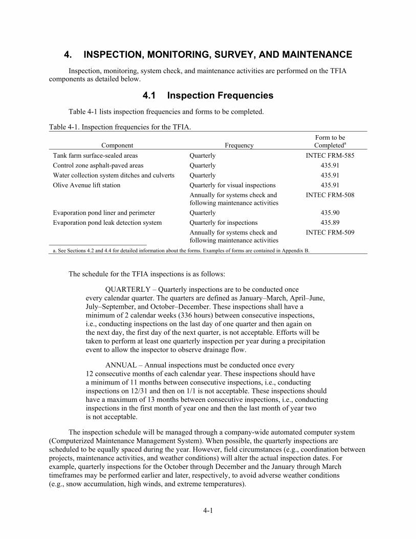
4.1 Inspection Frequencies Table 4-1 lists inspection frequencies and forms to be completed.
Table 4-1. Inspection frequencies for the TFIA.
Component Frequency Form to be Completeda
Tank farm surface-sealed areas Quarterly INTEC FRM-585 Control zone asphalt-paved areas Quarterly 435.91 Water collection system ditches and culverts Quarterly 435.91 Olive Avenue lift station Quarterly for visual inspections 435.91 Annually for systems check and
following maintenance activities INTEC FRM-508
Evaporation pond liner and perimeter Quarterly 435.90 Evaporation pond leak detection system Quarterly for inspections 435.89 Annually for systems check and
following maintenance activities INTEC FRM-509
a. See Sections 4.2 and 4.4 for detailed information about the forms. Examples of forms are contained in Appendix B.
The schedule for the TFIA inspections is as follows:
QUARTERLY – Quarterly inspections are to be conducted once every calendar quarter. The quarters are defined as January–March, April–June, July–September, and October–December. These inspections shall have a minimum of 2 calendar weeks (336 hours) between consecutive inspections, i.e., conducting inspections on the last day of one quarter and then again on the next day, the first day of the next quarter, is not acceptable. Efforts will be taken to perform at least one quarterly inspection per year during a precipitation event to allow the inspector to observe drainage flow.
ANNUAL – Annual inspections must be conducted once every 12 consecutive months of each calendar year. These inspections should have a minimum of 11 months between consecutive inspections, i.e., conducting inspections on 12/31 and then on 1/1 is not acceptable. These inspections should have a maximum of 13 months between consecutive inspections, i.e., conducting inspections in the first month of year one and then the last month of year two is not acceptable.
The inspection schedule will be managed through a company-wide automated computer system (Computerized Maintenance Management System). When possible, the quarterly inspections are scheduled to be equally spaced during the year. However, field circumstances (e.g., coordination between projects, maintenance activities, and weather conditions) will alter the actual inspection dates. For example, quarterly inspections for the October through December and the January through March timeframes may be performed earlier and later, respectively, to avoid adverse weather conditions (e.g., snow accumulation, high winds, and extreme temperatures).

4-2
4.2 Quarterly Inspection Forms Scheduled inspections shall be documented using the forms listed in Table 4-2.
Table 4-2. List of forms used to document scheduled TFIA inspections.
Form Number Title 435.89 Inspection of Evaporation Pond Leak Detection System 435.90 Inspection of Evaporation Pond Liner and Perimeter 435.91 Storm Water Collection System Outside Tank Farm Inspection INTEC FRM-585 INTEC Inspections Tank Farm Surface Sealed Areas
Each form contains the following:
• List of instructions
• List of components to inspect
• Comments/observations section
• Action item section
• Area for inspector and supervisor’s names, signatures, date
• Area to list and describe photographs taken and attached to the form.
Forms are revised as necessary to reflect changing field conditions and/or improvements in the inspection process. Examples of these forms are contained in Appendix B; however, the most current form revisions are maintained in EDMS under their form numbers. Completed forms are submitted to Document Control for inclusion into the project files. Information contained in the “Action Item” section of each form is entered into a maintenance tracking system (see Section 4.5).
4.3 Contingency Inspections Contingency inspections (unscheduled, situation-unique inspections performed upon direction of
the facility manager) will be conducted when operational integrity of the system has been or may be threatened. Events that might trigger contingency inspections include severe rainstorms, floods, or highly unusual events such as tornadoes and earthquakes. The inspector shall use the inspection forms (listed in Section 4.2) to inspect and report on items identified that threaten operational integrity. Items identified will be entered into a maintenance tracking system for action, and results of contingency inspections will be discussed in the annual operations report (Section 5).
4.4 Annual System Checks The TFIA contains two active systems, the Olive Avenue lift station and the evaporation pond leak
detection system, as described in Sections 3.4 and 3.6 respectively. To verify operability of the systems and to identify potential maintenance or repair items, system checks are performed annually and after repairs have been completed (as necessary). The forms used to document the system checks are
• INTEC FRM-508, “Annual CPP-1792 Lift Station System Checks Data Sheet”
• INTEC FRM-509, “Annual CPP-1793 System Checks for Evaporation Pond Leak Detection Sump Pump Controls Data Sheet.”

4-3
Forms are revised as necessary to reflect changing field conditions and/or improvements in the inspection process. Examples of these forms are contained in Appendix B; however, the most current form revisions are maintained in EDMS under their form numbers.
The systems checks shall be performed by qualified and knowledgeable personnel identified by the Utilities, Tenant, and Support Operations facility manager as directed by the MSCP facility manager. The forms, listed above, shall be used to document the activities, and copies of completed forms will be forwarded to the MSCP facility manager or designee who shall submit the forms to Document Control for inclusion into the project files. Although annual system checks can be performed anytime during the year, the desire is to have them completed during the summer months (June–August) to take advantage of favorable weather conditions and to allow for sufficient time to complete any necessary repairs before winter. Maintenance items identified on the completed forms will be addressed through the work control system. Maintenance items, deficiencies, or concerns noted on the system checks forms are entered into a maintenance tracking system for further monitoring or necessary action (see Section 4.5).
4.5 Maintenance Noted items from inspection forms, system checks, or other activities shall be entered into a
company-maintained computer software-based tracking system. The system shall be used to initiate maintenance activities, document the process, and track maintenance progress through completion.
Items requiring maintenance or repair will be addressed using the work control system (minor maintenance, preventative maintenance, corrective maintenance, etc); subcontract; or other means deemed appropriate by the facility manager or designee.
Due to their configuration, proximity to roadways, and the area’s frequent strong winds, many of the TFIA ditches accumulate debris which can interfere with water flow. To respond to this reoccurring issue, a preventative maintenance activity is currently in place and is scheduled to activate during the months of March, May, August, and October for debris removal.
Standard O&M procedures for the TFIA equipment are integrated into the INTEC documentation to provide proper maintenance for operation. As required, corrective maintenance of equipment and systems will be performed, which consists of unplanned repairs or replacement of system components after they have failed. Examples could be worn-out pumps, leaky pipes, damaged concrete or asphalt, and malfunctioning electronic equipment.
4.6 Monitoring Requirements Changing conditions may necessitate the need for additional monitoring that is not specifically
described in this O&M Plan. For example, unusually high water levels in the evaporation pond may necessitate the need for daily or weekly monitoring of conditions to ensure operability of the system or to assist in the diagnosis of deficiencies. Monitoring activities will be performed per the direction of the MSCP facility manager, and actions/findings will be documented in the annual operations report.
4.7 Radiological Surveys Radiological Control personnel, in accordance with Idaho National Laboratory (INL) radiological
monitoring and control policies, monitor the TFIA lined drainage ditches for radiological contamination or changes in conditions (radiological monitoring is not a requirement of this O&M Plan but changing conditions are documented on TFIA inspection forms). The focus, frequency, and method of this monitoring are identified by the INTEC Radiological Control supervisor, in accordance with the
4-4
requirements of 10 CFR 835.401 and 10 CFR 835.1102, as implemented at the INL Site in PRD-183. Currently, radiological surveys are performed weekly unless ditches are wet or snow-covered. Results are recorded on Form 441.45 and filed in the INTEC Radiological Control office. Radiological surveys are currently not performed or required on any TFIA asphalted areas or within the evaporation pond fenced area.
4.8 Diverted Water to the Evaporation Pond Nonhazardous, nonradiologically regulated waters discharged directly to the ground can contribute
to the transport of contaminants to the perched water. Where possible, these waters will be diverted to the evaporation pond in lieu of being discharged to the ground and potentially contributing to the perched water in the proximity of the tank farm. Waters from specific, controlled systems can be directly diverted to the lined ditches without prior approval or notifications. These waters include raw water, fire water, steam condensate water, potable water, demineralized water, and demineralized system backwash water. These plant waters would not have come into contact with radiologically controlled systems or hazardous waste.
In the proximity of the tank farm drainage system are utility tunnels, sumps, and similar areas that may collect water from events such as storm water run-off or breaks in potable water or fire water lines. This water is potentially contaminated due to contact with chemical constituents or radionuclides and shall undergo a one-time sampling event before the first transfer of this water to the TFIA drainage system can take place. The water will be sampled and assessed for constituents potentially contaminating the water (e.g., volatile organic compounds, semivolatile organic compounds, total petroleum hydrocarbon (also called TPH), total metals, and radionuclides). These analytical results and process knowledge will be used for a waste determination prior to discharge since the system is not designed to accept water that is a hazardous waste or determined to be radiologically regulated. This action will be performed for each new discharge prior to the initial discharge into the TFIA lined ditches.
The generator of diverted waters shall coordinate with Waste Generator Services to (a) determine what constituents could reasonably be present; (b) prepare the sampling plan, perform sampling, have the analysis performed; and (c) prepare the hazardous waste determination. All waters diverted to the TFIA evaporation pond shall be nonhazardous and nonradiologically controlled per Department of Energy Order 5400.5. Upon completion of water sampling and analysis, a waste determination will be performed. Following completion of the Waste Determination and Disposition Form (Form 435.39) that documents that the water is nonhazardous and nonradiologically controlled, it may be discharged to the TFIA system upon approval of the facility manager.
4.9 Lift Station and Leak Detection Control Panels 4.9.1 Control Panel Inspections
The control panels at the Olive Avenue lift station and the evaporation pond leak detection system are visually inspected daily by facility operators as part of an INTEC “utilities outside equipment checks” process. The condition of the panels are recorded on a round sheet and completed sheets are submitted to INTEC Document Control. Abnormal conditions are reported to the TFIA system engineer by the operations lead.

4-5
4.9.2 High-Water Indicators
The control panels at the Olive Avenue lift station and the evaporation pond leak detection system are equipped with both visual and audible high-water indicators. When activated, they indicate that the water level in either the lift station or in the leak detection sump has reached a preset high-water level. Contact information is posted on the front of each control panel which reads:
“For more information contact WAG 3 at 526-1515.”
In the event a high-water indicator is activated, observers can use the posted contact information to notify the facility manager and obtain instruction on how to respond to the indicators.

4-6

5-1
5. ANNUAL OPERATIONS REPORT
An annual operations report for the TFIA will be prepared and submitted to the Environmental Protection Agency, Idaho Department of Environmental Quality, and Department of Energy Idaho Operations Office (DOE-ID). The report may include the following:
• A summary of scheduled and contingency inspections performed
• Results of system checks for the Olive Avenue lift station and evaporation pond leak detection system
• Evaporation pond leak detection system monitoring data
• A summary of pond sediment sampling and analysis results for sediment to be removed
• A summary of maintenance activities performed
• Projected maintenance activities required for the next year
• A summary of any new source of diverted water and sample results.

5-2

6-1
6. RESPONSIBILITIES
The organizations that have responsibilities under this O&M Plan for inspections, support, repairs, reporting, and notifications are identified below.
6.1 DOE-ID WAG 3 Project Manager
The DOE-ID, OU 3-13, remediation project manager is responsible for overseeing the implementation of this plan in accordance with the FFA/CO.
6.2 Miscellaneous Sites Manager
The MSCP facility manager is responsible for ensuring that all TFIA components are adequately inspected, maintained, and repaired as per the requirements of this O&M Plan. Support shall be provided by other facility managers as listed below. Specific responsibilities include
• Operating, maintaining, and inspecting the TFIA equipment and components
• Assigning a qualified individual to perform quarterly inspections
• Implementing inspections outside the tank farm and signing completed inspection forms
• Sampling activities, sample analysis, interpretation, and corrective actions
• Interacting with Comprehensive Environmental Response, Compensation and Liability Act (CERCLA) Agencies on O&M Plan content and implementation
• Submitting documents, such as the annual operations reports or revised O&M plans, to CERCLA Agencies
• Providing technical interpretations direction to facility managers on meeting O&M Plan requirements for inspections and maintenance activities and recordkeeping
• Receiving and recording inspection reports and submitting records to records management
• Recording and tracking to completion any maintenance and repair-related activities
• Assuring document control of completed forms, O&M Plan, and O&M reports, including their placement in the project files and the CERCLA record files, as necessary.
6.3 Tank Farm Manager
The INTEC High Level Waste manager is the facility manager of the tank farm and is responsible for the grounds and systems located within the tank farm. Specific responsibilities include
• Maintaining the TFIA components (asphalt, drain pipes, filter socks, culverts, lined ditches) within the boundary of the tank farm in accordance with this O&M Plan
• Implementing inspections inside the tank farm by using personnel familiar with the system as constructed and operated
• Submitting completed TFIA forms to Document Control

6-2
• Submitting copies of all forms completed to the MSCP facility manager no more than 30 days after completion
• Submitting changes to the O&M Plan, as needed, to the MSCP facility manager
• Implementing and coordinating preventative and corrective maintenance activities
• Implementing follow-up inspections after repair or replacement activities
• Administrating subcontracts for performing required maintenance activities
• Maintaining a record of the maintenance activities performed
• Notifying MSCP facility manager if asphalt repairs will not be completed within 30 days of discovery.
6.4 Utilities, Tenant and Support Operations Facility Manager
The utilities, tenant and support operations manager is the facility manager of most roads and grounds inside and outside of INTEC. In addition, he is responsible for most buildings and structures inside and outside of INTEC not specifically identified as being the responsibility of another facility manager. Specific responsibilities include
• Completing system checks of the Olive Avenue lift station and evaporation pond leak detection system
• Implementing follow-up system checks after repair or replacement activities
• Protecting, repairing, and replacing all asphalted surface areas (to include roads), located outside the perimeter of the tank farm that are within the 150-ft control zone
• Ensuring that instigated or observed activities do not interfere with the operational capability of the TFIA system
• Submitting completed forms to Document Control
• Submitting copies of all forms completed to the MSCP facility manager no more than 30 days after completion
• Submitting changes to the O&M Plan, as needed, to the MSCP facility manager.
6.5 Radiological Control Manager
The Radiological Control manager has the following responsibilities:
• Perform weekly radiological surveys of TFIA lines ditches located outside the tank farm fence (unless ditches are wet or snow-covered)
• Document results of radiological surveys
• Administer requirements as detailed in PRD-183.

7-1
7. RECORDS
Inspection forms (to include system checks) shall be completed per the requirements of this plan. Forms completed by MSCP personnel shall be retained in the project files for later transmittal to Records Management personnel. Forms completed in support of MSCP will be managed under the INTEC Document Control system. Copies of completed forms (and any associated records, notes, etc.) shall be transmitted to the MSCP facility manager or designee within 30 days of completion. Records generated as a result of the implementation of this plan are maintained as CERCLA records in accordance with the FFA/CO (DOE-ID 1991).

7-2

8-1
8. REFERENCES
10 CFR 835.401, 2002, “General requirements,” Code of Federal Regulations, Office of the Federal Register, February 4, 2002.
10 CFR 835.1102, 2002, “Control of areas,” Code of Federal Regulations, Office of the Federal Register, February 4, 2002.
DOE, 2003, United States Environmental Protection Agency, Idaho Department of Environmental Quality, United States Department of Energy, in the Matter of: the December 04, 2002, Notice of Violation and the December 20, 2002, Statement of Dispute, Agreement to Resolve Dispute, U.S. Environmental Protection Agency, Idaho Department of Environmental Quality, U.S. Department of Energy, February 21, 2003.
DOE O 5400.5, Change 2, 1993, “Radiation Protection of the Public and the Environment,” U.S. Department of Energy, January 1993.
DOE-ID, 1991, Federal Facility Agreement and Consent Order for the Idaho National Engineering Laboratory, Administrative Docket No. 1088-06-29-120, U.S. Department of Energy Idaho Operations Office; U.S. Environmental Protection Agency, Region 10; Idaho Department of Health and Welfare, December 4, 1991.
DOE-ID, 1999, Final Record of Decision, Idaho Nuclear Technology and Engineering Center, Operable Unit 3-13, DOE/ID-10660, Rev. 0, U.S. Department of Energy Idaho Operations Office, October 1999.
DOE-ID, 2003, Remedial Design/Remedial Action Work Plan for Group 1, Tank Farm Interim Action, DOE/ID-10772, Rev. 1, U.S. Department of Energy Idaho Operations Office, September 2003.
DOE-NE-ID, 2005, Remedial Action Report for the Tank Farm Interim Action, WAG 3, OU 3-13, Group 1, Tank Farm Soils, DOE/NE-ID-11209, Rev. 0, U.S. Department of Energy Idaho Operations Office, June 2005.
Form 435.39, 2006, “Waste Determination & Disposition Form,” Rev. 8, Idaho National Laboratory, Idaho Cleanup Project, March 2006.
Form 435.89, “Inspection of Evaporation Pond Leak Detection System,” Rev. 1, Idaho National Laboratory, Idaho Cleanup Project, September 2006.
Form 435.90, “Inspection of Evaporation Pond Liner and Perimeter,” Rev. 1, Idaho National Laboratory, Idaho Cleanup Project, September 2006.
Form 435.91, “Storm Water Collection System Outside Tank Farm Inspection,” Rev. 2, Idaho National Laboratory, Idaho Cleanup Project, September 2006.
Form 441.45, 1997, “Radiological Survey Report,” Rev. 3, Idaho National Laboratory, Idaho Cleanup Project, October 1997.
FRM-508, 2005, “Annual CPP-1792 Lift Station System Checks Data Sheet,” Rev. 0, Idaho National Laboratory, Idaho Cleanup Project, December 2005.

8-2
FRM-509, 2005, “Annual CPP-1793 System Checks for Evaporation Pond Leak Detection Sump Pump Controls Data Sheet,” Rev. 0, Idaho National Laboratory, Idaho Cleanup Project, December 2005.
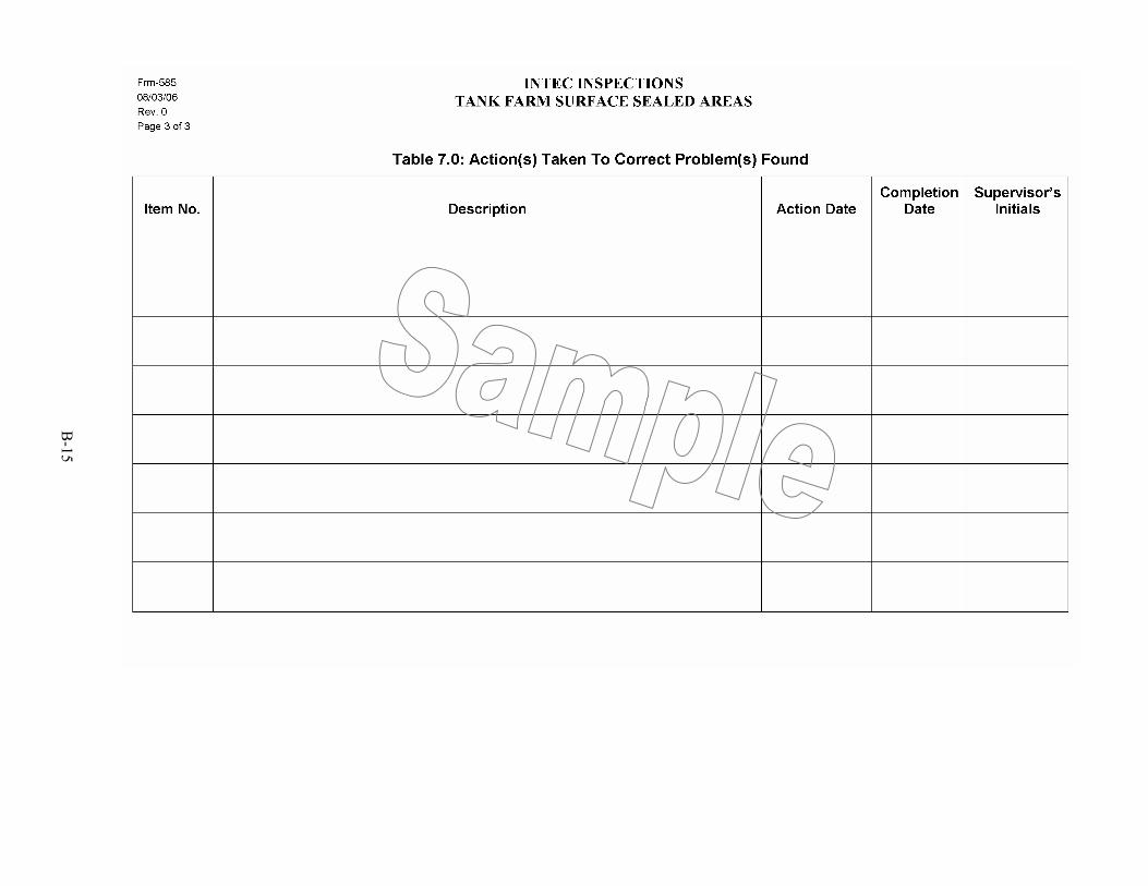
FRM-585, 2006, “INTEC Inspections Tank Farm Surface Sealed Areas,” Rev. 0, Idaho National Laboratory, Idaho Cleanup Project, August 2006.
PRD-183, 2006, “Radiological Control Manual,” Rev. 9, Idaho National Laboratory, Idaho Cleanup Project, June 2006.
A-1
Appendix A
Asphalt Classification System

A-2

A-3
Appendix A
Asphalt Classification System The following asphalt classification will be used during inspections of TFIA asphalted and
surface-sealed areas to establish criteria for determining maintenance requirements. The classification system uses a numbering system from 0 to 4 that corresponds to the following:
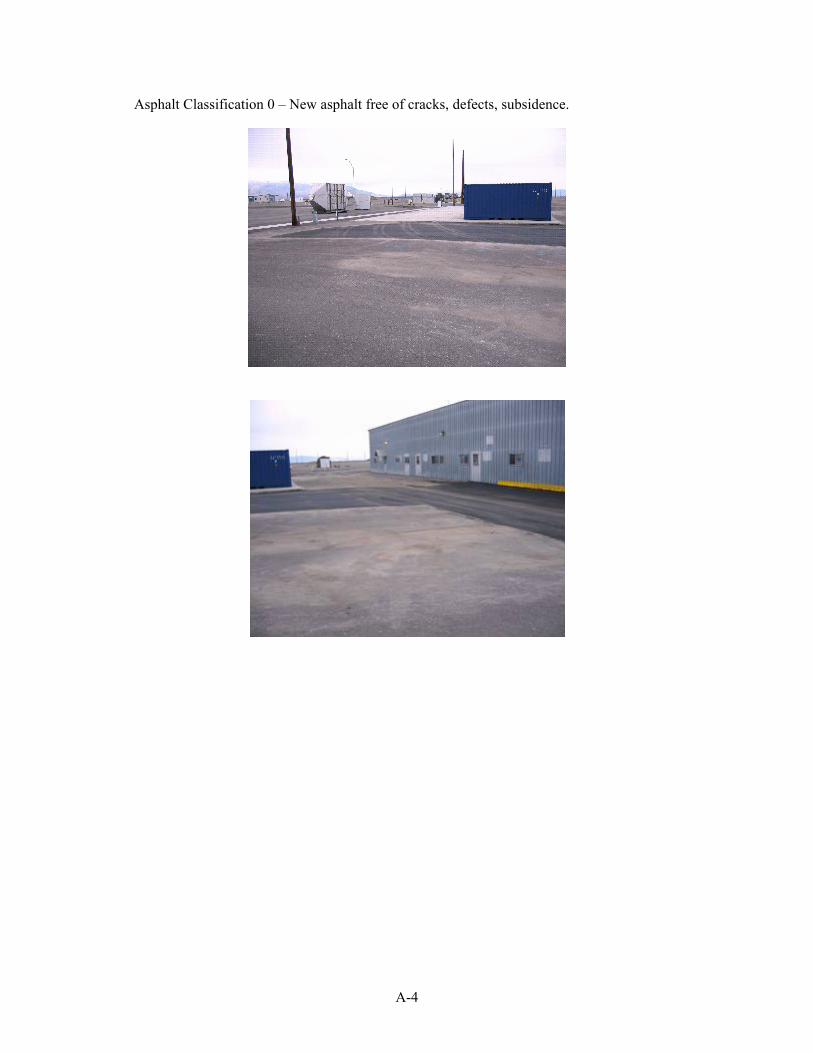
• Asphalt Classification 0 – New asphalt free of cracks, defects, subsidence.
• Asphalt Classification 1 – Existing asphalt in good condition, maintenance not required.
• Asphalt Classification 2 – May contain minor cracks, slight uneven surface, and/or may contain areas that have previously been repaired. Requires regular inspections.
• Asphalt Classification 3 – Contains cracks, holes, subsidence that require repair. Deep-patterned cracks that extend through the surface and reach the subgrade and base material.
• Asphalt Classification 4 – Asphalt containing major defect(s), requires replacement.
A-4
Asphalt Classification 0 – New asphalt free of cracks, defects, subsidence.

A-5
Asphalt Classification 1 – Existing asphalt free from cracks, hole, defects, subsidence.

A-6
Asphalt Classification 2 – May contain minor cracks, slight uneven surface, and/or may contain areas that have previously been repaired. May require regular monitoring.

A-7
Asphalt Classification 3 – Contains cracks, holes, subsidence that require repair. Deep-patterned cracks that may extend through the surface and reach the subgrade and base material.

A-8
Asphalt Classification 4 - Asphalt containing major defect(s), requires replacement.
B-1
Appendix B
Examples of TFIA Inspection Forms NOTE: These forms are for reference only. Use the most current version as
provided in the Idaho Cleanup Project Electronic Document Management System.

B-2
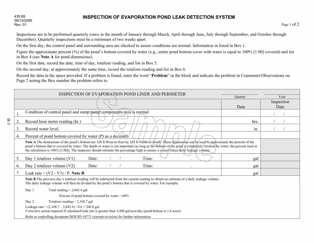
435.89 09/13/2006 Rev. 01
INSPECTION OF EVAPORATION POND LEAK DETECTION SYSTEM Page 1 of 2
B-3
Inspections are to be performed quarterly (once in the month of January through March, April through June, July through September, and October through December). Quarterly inspections must be a minimum of two weeks apart. On the first day, the control panel and surrounding area are checked to assure conditions are normal. Information in listed in Box 1. Figure the approximate percent (%) of the pond’s bottom covered by water (e.g., entire pond bottom cover with water is equal to 100% [1.00] covered) and list in Box 4 (see Note A for pond dimensions). On the first date, record the date, time of day, totalizer reading, and list in Box 5. On the second day, at approximately the same time, record the totalizer reading and list in Box 6. Record the data in the space provided. If a problem is found, enter the word “Problem” in the block and indicate the problem in Comments/Observations on Page 2 noting the Box number the problem refers to.
INSPECTION OF EVAPORATION POND LINER AND PERIMETER Quarter Year
Data Inspection
Date
1. Condition of control panel and sump pump components/area is normal. / /
2. Record hour meter reading (hr.) hrs. / /
3. Record water level. in. / /
4. Percent of pond bottom covered by water (P) as a decimal).
Note A The dimensions of the pond’s bottom are 320 ft West-to-East by 243 ft North-to-South. These dimensions can be used to approximate the percent of the pond’s bottom that is covered by water. The depth or water is not important (as long as the bottom of the pond is completely covered by water, the percent used in the calculation is 100% [1.00]). The inspector should estimate the percentage high to ensure a conservative daily leakage volume.
5. Day 1 totalizer volume (V1) Date: / / Time: . gal
6. Day 2 totalizer volume (V2) Date: / / Time: . gal
7. Leak rate = (V2 - V1) / P. Note B gal
Note B The previous day’s totalizer reading will be subtracted from the current reading to obtain an estimate of a daily leakage volume. The daily leakage volume will then be divided by the pond’s bottom that is covered by water. For example:
Day 1 Total reading = 2,043.4 gal Percent of pond bottom covered by water = 60% Day 2 Totalizer reading = 2,168.7 gal
Leakage rate = (2,168.7 – 2,043.6) / 0.6 = 208.8 gal Corrective action required if calculated leak rate is greater than 3,400 gal/acre/day (pond bottom is 1.8 acres)
Refer to controlling document DOE/ID-10771 (current revision) for further information
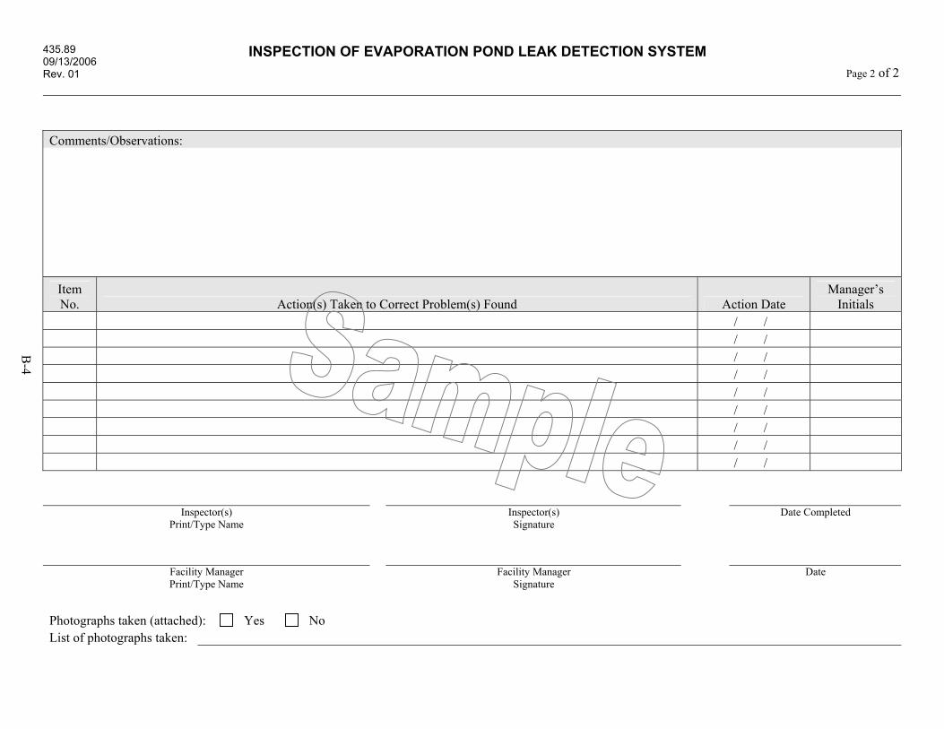
435.89 09/13/2006 Rev. 01
INSPECTION OF EVAPORATION POND LEAK DETECTION SYSTEM Page 2 of 2
B-4
Comments/Observations:
Item No. Action(s) Taken to Correct Problem(s) Found Action Date
Manager’s Initials
/ / / / / / / / / / / / / / / /
/ /
Inspector(s)
Print/Type Name Inspector(s)
Signature Date Completed
Facility Manager Print/Type Name
Facility Manager Signature
Date
Photographs taken (attached): Yes No List of photographs taken:

435.90 09/13/2006 Rev. 01
INSPECTION OF EVAPORATION POND LINER AND PERIMETER Page 1 of 2
B-5
Inspections are to be performed quarterly (once in the months of January through March, April through June, July through September, and October through December). Quarterly inspections must be a minimum of two weeks apart. Enter “YES” in the “Normal Conditions” block if no problems are noted. Enter “NO” in the “Off Spec Conditions” block if no problems are noted. If a problem is found, enter the word “problem” in the block and indicate the problem item along with associated corrective action in the comments/observations section.
INSPECTION OF EVAPORATION POND LINER AND PERIMETER Quarter Year
Inspection Activity Normal
Condition Off Spec Condition
1. Liner integrity – Liner is free of rips and tears. No environmental degradation observed. No evidence of animal intrusion.
2. Liner integrity – No visible vegetation piercing the liner. Liner not under excessive tension.
3. Liner anchor – Liner anchors are in place and in good condition.
4. Fencing – chain link fencing and gate in good condition. Lock is in place. Signage is in place.
5. Sediment and debris – No excessive sediment or debris in pond bottom (i.e., covering the bottom).
6. Inspect pond inlet and outlets for debris and sediment.
7. Personal floatation/rescue devices are in place inside the fenced area (three on each side).
8. Radiological controls – No new or additional radiological controls have been indicated. Comments/Observations:

435.90 09/13/2006 Rev. 01
INSPECTION OF EVAPORATION POND LINER AND PERIMETER Page 2 of 2
B-6
Item No. Action(s) Taken to Correct Problem(s) Found Action Date Manager’s
Initials
/ /
/ /
/ /
/ /
/ /
/ /
/ /
/ /
/ /
/ /
Inspector
Print/Type Name Inspector
Signature Date Completed
Facility Manager Print/Type Name
Facility Manager Signature
Date
Photographs taken (attached): Yes No Lists of photographs taken:
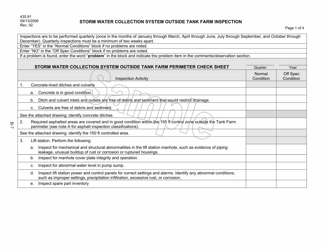
435.91 09/13/2006 Rev. 02
STORM WATER COLLECTION SYSTEM OUTSIDE TANK FARM INSPECTION Page 1 of 4
B-7
Inspections are to be performed quarterly (once in the months of January through March, April through June, July through September, and October through December). Quarterly inspections must be a minimum of two weeks apart. Enter “YES” in the “Normal Conditions” block if no problems are noted. Enter “NO” in the “Off Spec Conditions” block if no problems are noted. If a problem is found, enter the word “problem” in the block and indicate the problem item in the comments/observation section.
STORM WATER COLLECTION SYSTEM OUTSIDE TANK FARM PERIMETER CHECK SHEET Quarter Year
Inspection Activity Normal
Condition Off Spec Condition
1. Concrete-lined ditches and culverts
a. Concrete is in good condition.
b. Ditch and culvert inlets and outlets are free of debris and sediment that would restrict drainage.
c. Culverts are free of debris and sediment.
See the attached drawing; identify concrete ditches. 2. Required asphalted areas are covered and in good condition within the 150 ft control zone outside the Tank Farm
perimeter (see note A for asphalt inspection classifications).
See the attached drawing; identify the 150 ft controlled area.
3. Lift station. Perform the following: a. Inspect for mechanical and structural abnormalities in the lift station manhole, such as evidence of piping
leakage, unusual buildup of rust or corrosion or ruptured housings.
b. Inspect for manhole cover plate integrity and operation.
c. Inspect for abnormal water level in pump sump.
d. Inspect lift station power and control panels for correct settings and alarms. Identify any abnormal conditions, such as improper settings, precipitation infiltration, excessive rust, or corrosion.
e. Inspect spare part inventory

435.91 09/13/2006 Rev. 02
STORM WATER COLLECTION SYSTEM OUTSIDE TANK FARM INSPECTION Page 2 of 4
B-8
Inspection Activity Normal
Condition Off Spec Condition
4. Radiological controls: Are there new or additional radiological controls that have been identified? (A) Asphalt Classification System
The following asphalt classification will be used during inspections of TFIA asphalted and surface-sealed areas to establish criteria for determining maintenance requirements. The classification system uses a numbering system from 0 to 4 that corresponds to the following:
• Asphalt Classification 0 – New asphalt free of cracks, defects, subsidence. • Asphalt Classification 1 – Existing asphalt in good condition, maintenance not required. • Asphalt Classification 2 – Minor cracks, slight uneven surface, previously been repaired. • Asphalt Classification 3 – Penetrating cracks, holes, subsidence that require repair. • Asphalt Classification 4 – Contains major defect(s) requires replacement.
Comments/Observations:

435.91 09/13/2006 Rev. 02
STORM WATER COLLECTION SYSTEM OUTSIDE TANK FARM INSPECTION Page 3 of 4
B-9
Item No. Action(s) Taken to Correct Problem(s) Found Action Date Manager’s
Initials
/ /
/ /
/ /
/ /
/ /
/ /
/ /
/ /
/ /
/ /
/ /
/ /
/ /
Inspector
Print/Type Name Inspector
Signature Date Completed
Facility Manager Print/Type Name
Facility Manager Signature
Date
Photographs taken (attached): Yes No Lists of photographs taken:

435.91 09/13/2006 Rev. 02
STORM WATER COLLECTION SYSTEM OUTSIDE TANK FARM INSPECTION Page 4 of 4
B-10

B-11

B-12

B-13
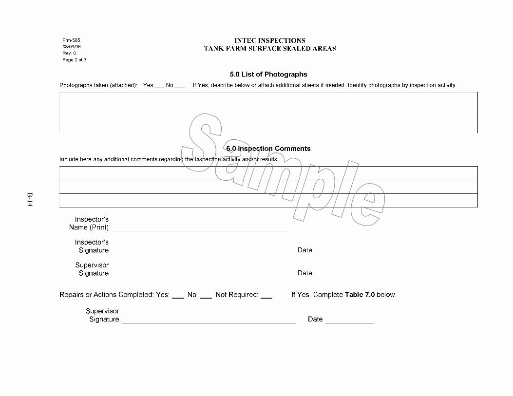
B-14
B-15