Embed Size (px)
Citation preview
.
Operation and Maintenance of the
Ultra II Model Bumper Boy Retriever Trainer
Bumper Boy Inc.
Revision 3 Feb. 2007
BB Trainer Revision 3.doc
i
Table of Contents
Title Page
Introduction ..............................................................................1 Introduce Your Dog to Bumper Boy .........................................1 Components of the Bumper Boy Ultra II Model .......................2
Standard Ultra II Package....................................................2 Optional Equipment .............................................................3
Bumper Boy Description ..........................................................5 Pro Transmitter....................................................................5 Ultra II Launcher ..................................................................9
Theory of Operation................................................................14 Quick Start Your Bumper Boy Ultra II Series System.............15
Unpack the Bumper Boy....................................................15 Assemble the Components................................................16
Charge the Receiver and Transmitter Batteries .................18 Program the Transmitter ....................................................19
Prepare for Field Operation ...................................................23 In House Test ....................................................................23 Load Test...........................................................................24
Safety ....................................................................................25 Operation in the Field .............................................................26 Plan the Scenario ..................................................................26
Configure the Launcher (Bi-Directional Mode) .......................27 Selecting Firing Order............................................................28 Field Setup ............................................................................29
Run the Scenario...............................................................32 Wet Weather Training........................................................34
Bumper Boy Maintenance ......................................................35 Bumper Care .....................................................................35 Launcher Care...................................................................35 Transmitter and Receiver Care..........................................35
Trouble Shooting Guide..........................................................36 Misfire....................................................................................36
Troubleshooting the launcher: ...............................................37 Sound does not work .............................................................37 Servo operates, but does not fire consistently .......................38 Firing pin will not cock............................................................39 Replacing a Servo .................................................................39
BB Trainer Revision 3.doc
ii
List of Figures
Figure Title Page
Figure 1 Standard Bumper Boy Ultra II Components................................................
2
Figure 2a
Advanced Sound System............................
3
Figure 2b
Superbirds...................................................
3
Figure 2c
Camo Case. ...............................................
3
Figure 3
Image/Motion Attachment...........................
4
Figure 4
Pro Transmitter...........................................
5
Figure 5
Ultra II Receiver..........................................
9
Figure 6
Toggle Switch..............................................
9
Figure 7
Bumper Boy Ultra II Frame and End Plates...................................................
11
Figure 8 Bumper Boy Launcher Assembly...............
11
Figure 9
Launcher Assembly Cutaway Drawing …...
13
Figure 10
Advanced Speaker Installation....................
17
Figure 11
Bumper Assembly.......................................
18
Figure 12
Battery Charger...........................................
18
BB Trainer Revision 3.doc
1
Introduction
Whether you're a hunter, field trailer, running hunt tests, using spaniels, pointers or retrievers, the Bumper Boy Ultra II series will provide you with reward-based training methods never before possible. This reward-based system will have the largest impact on your dog's ability to remember, retrieve, hunt, build desire and learn. This unique training system will provide your dog with a more enjoyable training experience, and help him learn faster. Whether you are teaching “sit to flush” or complicated multiple marks, you and your dog can look forward to increased enjoyment and more effective use of time. This sporting dog system is designed to simulate visual, and aural dynamics of a human training assistant, and the rapidly changing environment of a hunting experience. This method produces better marking dogs than any conventional training methods through use of reward-based techniques stressed by many world-renowned animal trainers such as Karen Pyior, PHD, an animal behavior expert with the University of San Diego. This manual applies to operation of all Bumper Boy Ultra II series models.
Introduce Your Dog to Bumper Boy
Like any new training tool the dog should be introduced to it properly. Introduce the new type of bumper; it may smell and fly differently than the bumpers you use. In some cases the dog thinks the flapping bumper is a live flyer and will hunt to find a bird. This is temporary and is quickly learned. Then introduce images, different sounds, motion and sound of shot. This can be accomplished in normal yard training. Now you will see your dog's eyes light up every time you put Bumper Boy into your car.
BB Trainer Revision 3.doc
2
Components of the Bumper Boy Ultra II
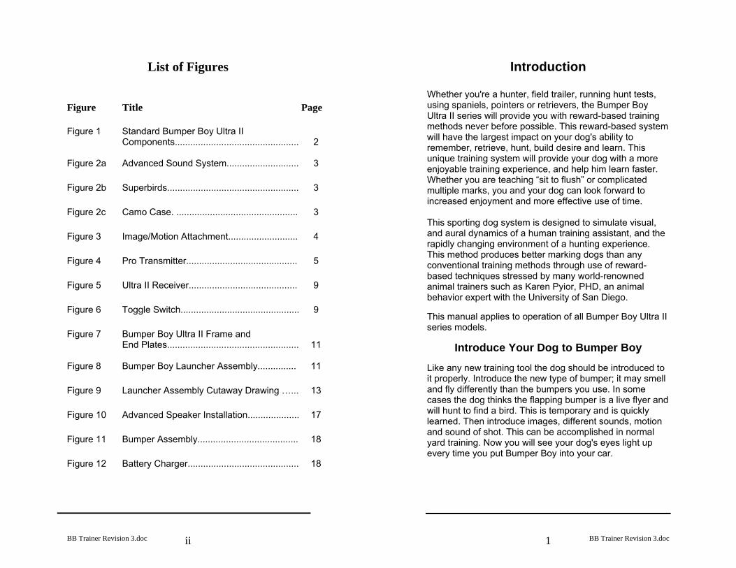
Standard Ultra II Package (Figure 1) Bi-Directional Launcher with receiver
100 blank .22 caliber shells
Pro transmitter
Owner’s manual
Battery charger
Standard speaker: Attention getting chirping sound
Two Smart Bumpers with streamers and throw
handles.
Figure 1. Standard Bumper Boy Ultra II Components
BB Trainer Revision 3.doc
3
Optional Equipment Advanced sound system– (Figure 2a) Duck, pheasant, goose, and human sound Very loud horn speaker
Super Birds– (Figure 2b) Provides a complete substitute for dead birds High-flying and very motivational
Camo Case– (Figure 2c) Carrying bag provides for easy field movement Case holds two launchers, with bumpers, and
electronics
Figure 2a: Figure 2b: Figure 2c. Advanced Sound Superbirds Camo Case System
BB Trainer Revision 3.doc
4
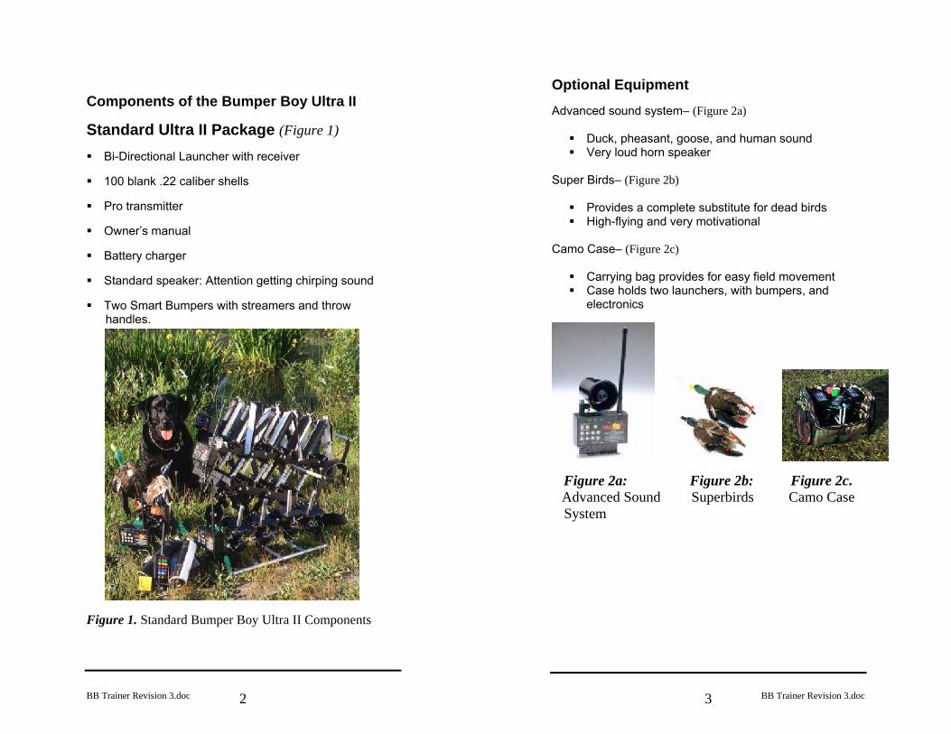
Double-sided gunner image with launcher mount and motion motor attachment (Figure 3) (Unit must have the advanced sound system) –
• Simulates the movement of a person in the field • Provides queuing, help, and simulates retired guns • Ultra-light and compact – 3lbs
Figure 3. Image/Motion Attachment
BB Trainer Revision 3.doc
5
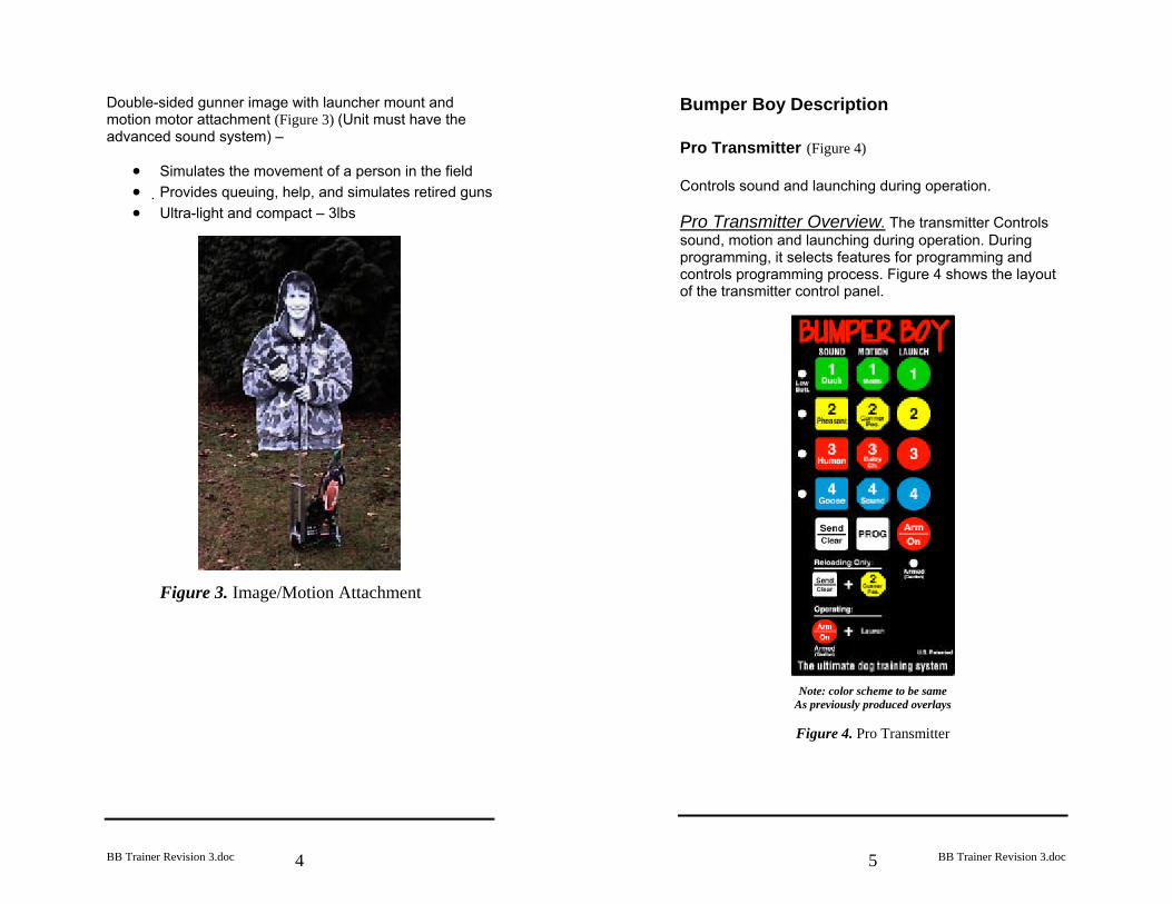
Bumper Boy Description Pro Transmitter (Figure 4) Controls sound and launching during operation. Pro Transmitter Overview. The transmitter Controls sound, motion and launching during operation. During programming, it selects features for programming and controls programming process. Figure 4 shows the layout of the transmitter control panel.
Note: color scheme to be same As previously produced overlays
Figure 4. Pro Transmitter
BB Trainer Revision 3.doc
6
3
Duck
1 2
3 4
3 Human
1 Duck
2 Pheasant
4 Goose
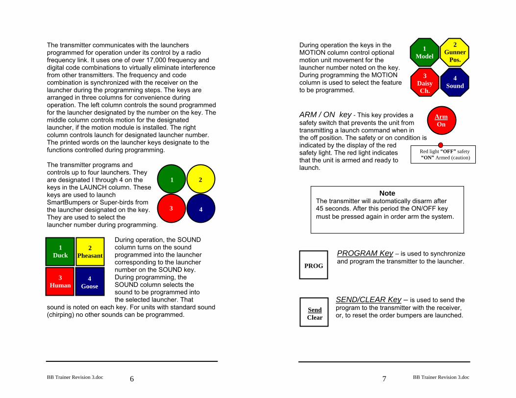
The transmitter communicates with the launchers programmed for operation under its control by a radio frequency link. It uses one of over 17,000 frequency and digital code combinations to virtually eliminate interference from other transmitters. The frequency and code combination is synchronized with the receiver on the launcher during the programming steps. The keys are arranged in three columns for convenience during operation. The left column controls the sound programmed for the launcher designated by the number on the key. The middle column controls motion for the designated launcher, if the motion module is installed. The right column controls launch for designated launcher number. The printed words on the launcher keys designate to the functions controlled during programming.
The transmitter programs and controls up to four launchers. They are designated I through 4 on the keys in the LAUNCH column. These keys are used to launch SmartBumpers or Super-birds from the launcher designated on the key. They are used to select the launcher number during programming.
During operation, the SOUND column turns on the sound programmed into the launcher corresponding to the launcher number on the SOUND key. During programming, the SOUND column selects the sound to be programmed into the selected launcher. That
sound is noted on each key. For units with standard sound (chirping) no other sounds can be programmed.
BB Trainer Revision 3.doc
7
Red light “OFF” safety “ON” Armed (caution)
1 Model
2 Gunner
Pos.
3 Daisy Ch.
4 Sound
Arm On
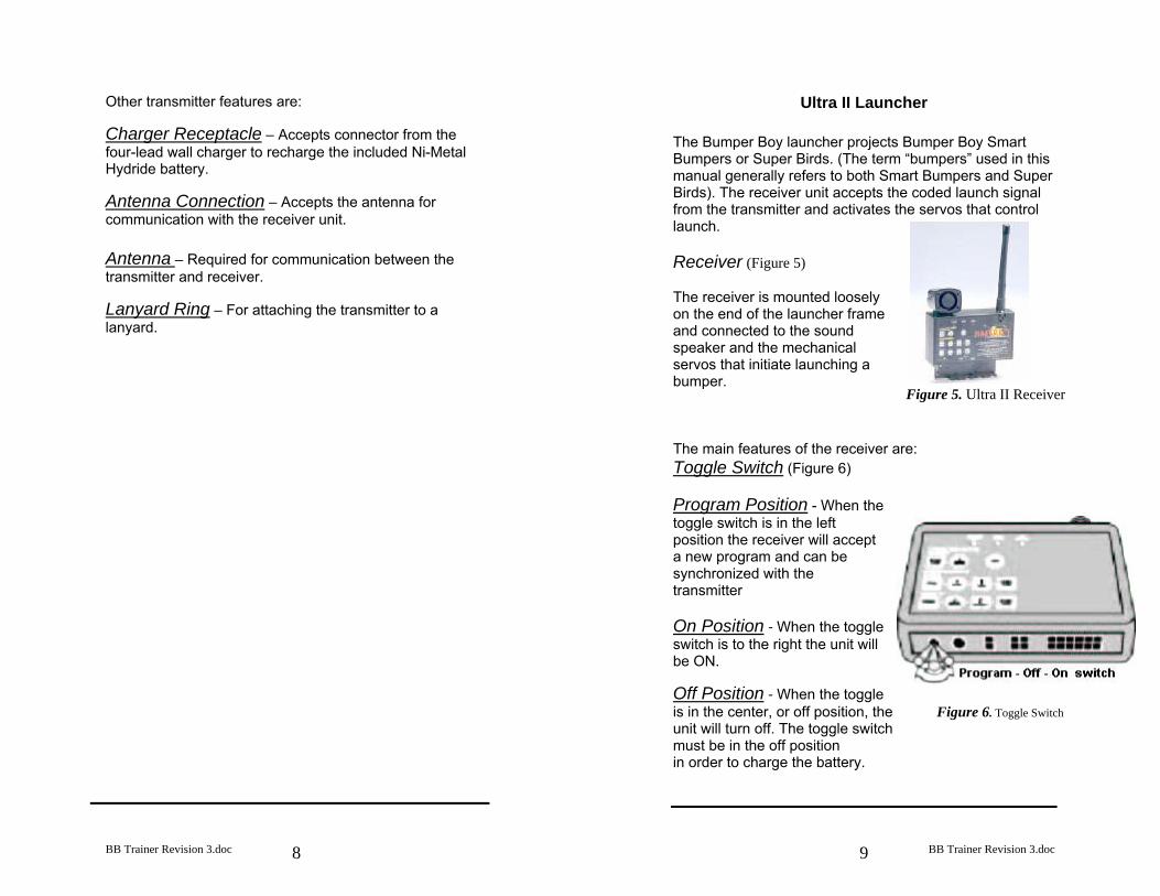
During operation the keys in the MOTION column control optional motion unit movement for the launcher number noted on the key. During programming the MOTION column is used to select the feature to be programmed. ARM / ON key - This key provides a safety switch that prevents the unit from transmitting a launch command when in the off position. The safety or on condition is indicated by the display of the red safety light. The red light indicates that the unit is armed and ready to launch.
PROGRAM Key – is used to synchronize and program the transmitter to the launcher.
SEND/CLEAR Key – is used to send the program to the transmitter with the receiver, or, to reset the order bumpers are launched.
PROG
Send Clear
Note The transmitter will automatically disarm after 45 seconds. After this period the ON/OFF key must be pressed again in order arm the system.
BB Trainer Revision 3.doc
8
Other transmitter features are: Charger Receptacle – Accepts connector from the four-lead wall charger to recharge the included Ni-Metal Hydride battery. Antenna Connection – Accepts the antenna for communication with the receiver unit. Antenna – Required for communication between the transmitter and receiver. Lanyard Ring – For attaching the transmitter to a lanyard.
BB Trainer Revision 3.doc
9
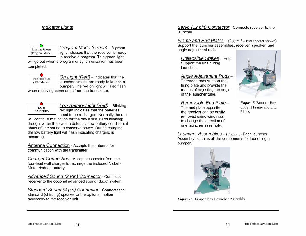
Ultra II Launcher The Bumper Boy launcher projects Bumper Boy Smart Bumpers or Super Birds. (The term “bumpers” used in this manual generally refers to both Smart Bumpers and Super Birds). The receiver unit accepts the coded launch signal from the transmitter and activates the servos that control launch. Receiver (Figure 5) The receiver is mounted loosely on the end of the launcher frame and connected to the sound speaker and the mechanical servos that initiate launching a bumper. The main features of the receiver are: Toggle Switch (Figure 6) Program Position - When the toggle switch is in the left position the receiver will accept a new program and can be synchronized with the transmitter On Position - When the toggle switch is to the right the unit will be ON. Off Position - When the toggle is in the center, or off position, the Figure 6. Toggle Switch unit will turn off. The toggle switch must be in the off position in order to charge the battery.
Figure 5. Ultra II Receiver
BB Trainer Revision 3.doc
10
Flashing Red ( ON Mode )
Indicator Lights
Program Mode (Green) – A green light indicates that the receiver is ready to receive a program. This green light
will go out when a program or synchronization has been completed.
On Light (Red) – Indicates that the launcher circuits are ready to launch a bumper. The red on light will also flash
when receiving commands from the transmitter.
Low Battery Light (Red) – Blinking red light indicates that the batteries need to be recharged. Normally the unit
will continue to function for the day it first starts blinking; though, when the system detects a low battery condition, it shuts off the sound to conserve power. During charging the low battery light will flash indicating charging is occurring. Antenna Connection - Accepts the antenna for communication with the transmitter. Charger Connection - Accepts connector from the four-lead wall charger to recharge the included Nickel - Metal Hydride battery. Advanced Sound (2 Pin) Connector - Connects receiver to the optional advanced sound (duck) system. Standard Sound (4 pin) Connector - Connects the standard (chirping) speaker or the optional motion accessory to the receiver unit.
Flashing Green (Program Mode)
LOW BATTERY
BB Trainer Revision 3.doc
11
Servo (12 pin) Connector - Connects receiver to the launcher. Frame and End Plates – (Figure 7 – two shooter shown) Support the launcher assemblies, receiver, speaker, and angle adjustment rods.
Collapsible Stakes – Help Support the unit during launches. Angle Adjustment Rods – Threaded rods support the firing plate and provide the means of adjusting the angle of the launcher tube. Removable End Plate – The end plate opposite the receiver can be easily removed using wing nuts to change the direction of one launcher assembly.
Launcher Assemblies – (Figure 8) Each launcher Assembly contains all the components for launching a bumper.
Figure 8. Bumper Boy Launcher Assembly
Figure 7. Bumper Boy Ultra II Frame and End Plates
BB Trainer Revision 3.doc
12
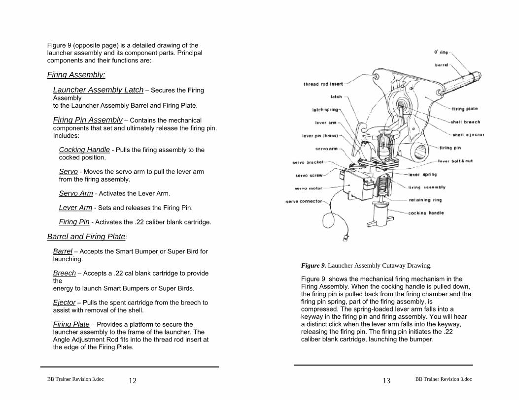
Figure 9 (opposite page) is a detailed drawing of the launcher assembly and its component parts. Principal components and their functions are: Firing Assembly:
Launcher Assembly Latch – Secures the Firing Assembly to the Launcher Assembly Barrel and Firing Plate. Firing Pin Assembly – Contains the mechanical components that set and ultimately release the firing pin. Includes:
Cocking Handle - Pulls the firing assembly to the cocked position. Servo - Moves the servo arm to pull the lever arm from the firing assembly. Servo Arm - Activates the Lever Arm. Lever Arm - Sets and releases the Firing Pin. Firing Pin - Activates the .22 caliber blank cartridge.
Barrel and Firing Plate:
Barrel – Accepts the Smart Bumper or Super Bird for launching. Breech – Accepts a .22 cal blank cartridge to provide the energy to launch Smart Bumpers or Super Birds. Ejector – Pulls the spent cartridge from the breech to assist with removal of the shell. Firing Plate – Provides a platform to secure the launcher assembly to the frame of the launcher. The Angle Adjustment Rod fits into the thread rod insert at the edge of the Firing Plate.
BB Trainer Revision 3.doc
13
Figure 9. Launcher Assembly Cutaway Drawing. Figure 9 shows the mechanical firing mechanism in the Firing Assembly. When the cocking handle is pulled down, the firing pin is pulled back from the firing chamber and the firing pin spring, part of the firing assembly, is compressed. The spring-loaded lever arm falls into a keyway in the firing pin and firing assembly. You will hear a distinct click when the lever arm falls into the keyway, releasing the firing pin. The firing pin initiates the .22 caliber blank cartridge, launching the bumper.
BB Trainer Revision 3.doc
14
Theory of Operation Bumper Boy provides a means to present a variety of training scenarios to your dogs. Radio links allow the trainer to control the scenario from the line. Digital coding virtually eliminates interference from other systems working in the immediate training area. Use of Bumper Boy accessories such as the motion simulator and sound module provide additional resources to help develop your dog’s skills. The Smart Bumpers, streamers, reversible bumper covers, and brass bumper weights allow you to further customize your training options based on your dog’s experience. The brass bumper weights are inserted into one of the two holes in the end of the smart bumper thus influencing its floatation displaying the color you choose. The Bumper Boy Ultra II Transmitter has two functions, 1) programming and synchronizing the receiver with the transmitter and 2) transmitting the signal to activate launcher functions, such as launching a bumper. The Bumper Boy Receiver accepts a valid code sequence and the launch signal and activates the launch servos to initiate launch. The launcher projects Smart Bumpers or Super Birds with energy generated by firing a .22 blank cartridge. If equipped, the trainer also activates the sound and motion remotely with the Bumper Boy transmitter. On receipt of the correct coded signal the receiver activates the speaker, motion servo or the launcher servo. The launcher assembly servo releases the launcher firing pin, firing the .22 cal cartridge.
BB Trainer Revision 3.doc
15
Quick Start Your Bumper Boy Ultra II Series System Unpack the Bumper Boy Make sure you have received all the equipment ordered. Standard Equipment:
Smart Bumpers (equal to the launcher assemblies on your system)
Streamers for the Bumpers
Power Handles, (black spheres with holes to
accommodate the bumper ropes), for hand throwing bumpers
Standard Speaker or Advanced Speaker
Wire Ties
Ultra II Launcher with Receiver
Pro Transmitter
Antenna – 2
Brass Bumper Weight on a Black String, for roll
over feature during water test. (Insert into appropriate hole at the top of the bumper.)
Silicone Grease, for occasional use on “O” rings
BB Trainer Revision 3.doc
16
Assemble the Components Transmitter Assembly Screw the antenna into the transmitter antenna
connection. Receiver Installation Mount receiver into the slotted area in the end plate.
Loosely fasten the receiver to the end plate, with the
antenna receptacle up, using the washers and nuts furnished.
Install the male 12-position launcher connector to
female connector on the receiver. Press firmly to make sure connector is engaged.
Secure the excess cable to the receiver with the wire
tie furnished. Install the antenna into the antenna connection.
Standard Speaker Installation (See Figure 5) Remove the Velcro Strip with the adhesive backing
from the Standard Speaker by separating it from the Velcro patch attached to the speaker.
Remove the adhesive backing from the Velcro strip
and attach the strip to the top of the receiver. Install the tape with the long axis along the long axis of the top of the receiver.
Note Do not tighten the receiver against the end plate.It should be mounted so that it will slide up and down easily in order to reduce the effect of recoil.
BB Trainer Revision 3.doc
17
Attach the small speaker to the Velcro. Orientation of the speaker can be changed to point toward the working dog in the field.
Route the speaker cable behind the end plate, through
the cable access slot, to the bottom of the receiver. Plug speaker into the 4-position plug on the receiver
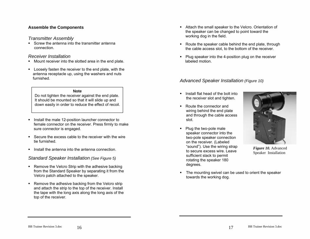
labeled motion. Advanced Speaker Installation (Figure 10) Install flat head of the bolt into
the receiver slot and tighten. Route the connector and
wiring behind the end plate and through the cable access slot.
Plug the two-pole male
speaker connector into the two-pole speaker connection on the receiver. (Labeled “sound”). Use the wiring strap to secure excess wire. Leave sufficient slack to permit rotating the speaker 180 degrees.
The mounting swivel can be used to orient the speaker
towards the working dog.
Figure 10. Advanced Speaker Installation
BB Trainer Revision 3.doc
18
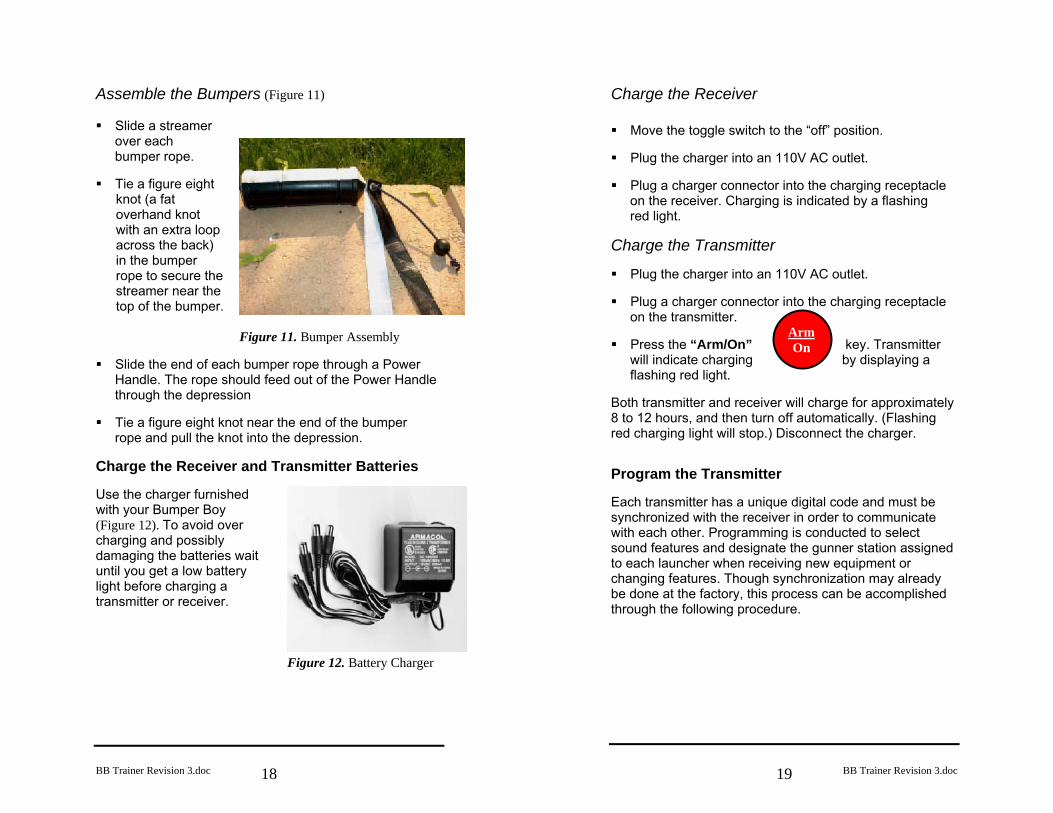
Assemble the Bumpers (Figure 11) Slide a streamer
over each bumper rope.
Tie a figure eight
knot (a fat overhand knot with an extra loop across the back) in the bumper rope to secure the streamer near the top of the bumper.
Figure 11. Bumper Assembly Slide the end of each bumper rope through a Power
Handle. The rope should feed out of the Power Handle through the depression
Tie a figure eight knot near the end of the bumper
rope and pull the knot into the depression. Charge the Receiver and Transmitter Batteries Use the charger furnished with your Bumper Boy (Figure 12). To avoid over charging and possibly damaging the batteries wait until you get a low battery light before charging a transmitter or receiver. Figure 12. Battery Charger
BB Trainer Revision 3.doc
19
Arm On
Charge the Receiver Move the toggle switch to the “off” position.
Plug the charger into an 110V AC outlet.
Plug a charger connector into the charging receptacle
on the receiver. Charging is indicated by a flashing red light.
Charge the Transmitter Plug the charger into an 110V AC outlet.
Plug a charger connector into the charging receptacle
on the transmitter. Press the “Arm/On” key. Transmitter
will indicate charging by displaying a flashing red light.
Both transmitter and receiver will charge for approximately 8 to 12 hours, and then turn off automatically. (Flashing red charging light will stop.) Disconnect the charger. Program the Transmitter Each transmitter has a unique digital code and must be synchronized with the receiver in order to communicate with each other. Programming is conducted to select sound features and designate the gunner station assigned to each launcher when receiving new equipment or changing features. Though synchronization may already be done at the factory, this process can be accomplished through the following procedure.
BB Trainer Revision 3.doc
20
1 Duck
4 Sound
Flashing Green (Program Mode)
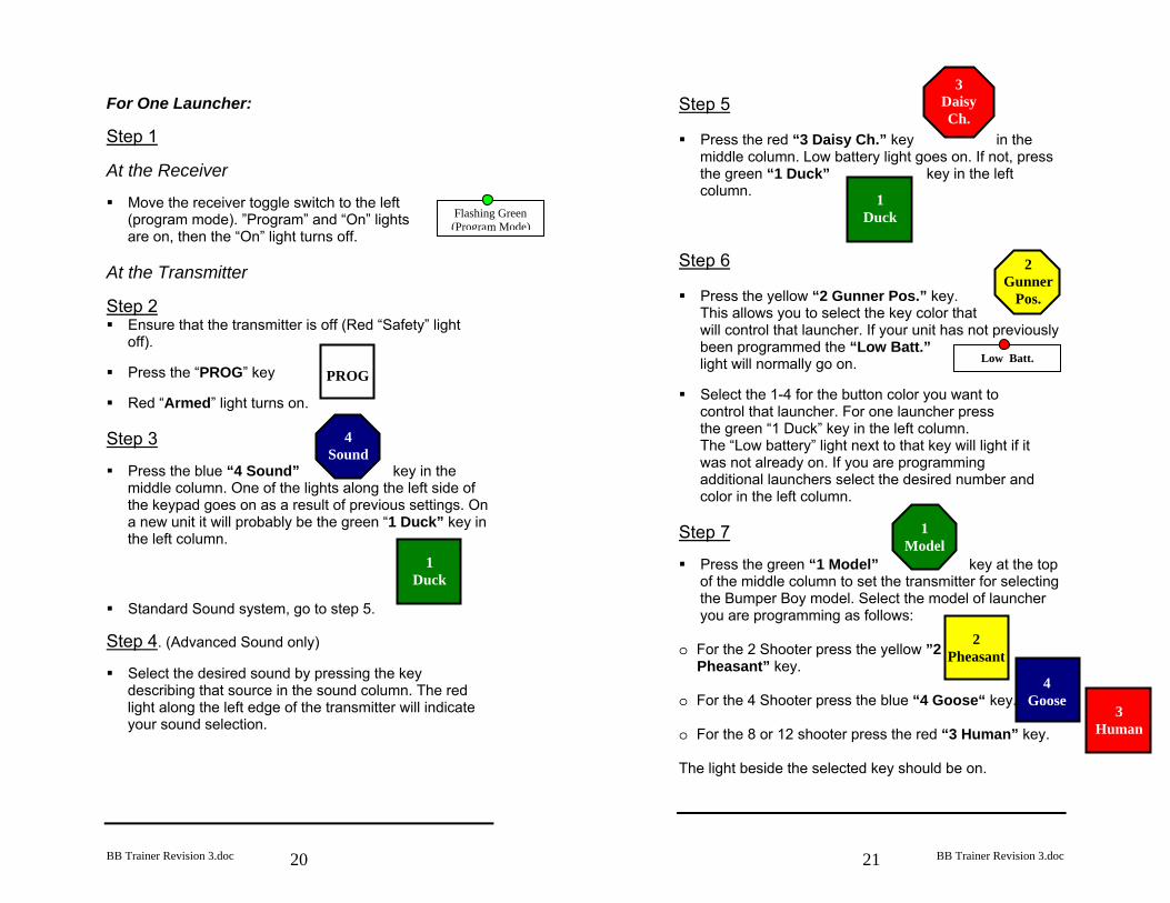
For One Launcher: Step 1 At the Receiver Move the receiver toggle switch to the left
(program mode). ”Program” and “On” lights are on, then the “On” light turns off.
At the Transmitter Step 2 Ensure that the transmitter is off (Red “Safety” light
off). Press the “PROG” key
Red “Armed” light turns on.
Step 3 Press the blue “4 Sound” key in the
middle column. One of the lights along the left side of the keypad goes on as a result of previous settings. On a new unit it will probably be the green “1 Duck” key in the left column.
Standard Sound system, go to step 5.
Step 4. (Advanced Sound only) Select the desired sound by pressing the key
describing that source in the sound column. The red light along the left edge of the transmitter will indicate your sound selection.
PROG
BB Trainer Revision 3.doc
21
2 Gunner
Pos.
1 Model
2 Pheasant
4 Goose
1 Duck
3 Daisy Ch.
3 Human
Low Batt.
Step 5 Press the red “3 Daisy Ch.” key in the
middle column. Low battery light goes on. If not, press the green “1 Duck” key in the left column.
Step 6 Press the yellow “2 Gunner Pos.” key.
This allows you to select the key color that will control that launcher. If your unit has not previously been programmed the “Low Batt.” light will normally go on.
Select the 1-4 for the button color you want to
control that launcher. For one launcher press the green “1 Duck” key in the left column. The “Low battery” light next to that key will light if it was not already on. If you are programming additional launchers select the desired number and color in the left column.
Step 7 Press the green “1 Model” key at the top
of the middle column to set the transmitter for selecting the Bumper Boy model. Select the model of launcher you are programming as follows:
o For the 2 Shooter press the yellow ”2
Pheasant” key. o For the 4 Shooter press the blue “4 Goose“ key.. o For the 8 or 12 shooter press the red “3 Human” key. The light beside the selected key should be on.
BB Trainer Revision 3.doc
22
3 Human
4 Goose
Send Clear
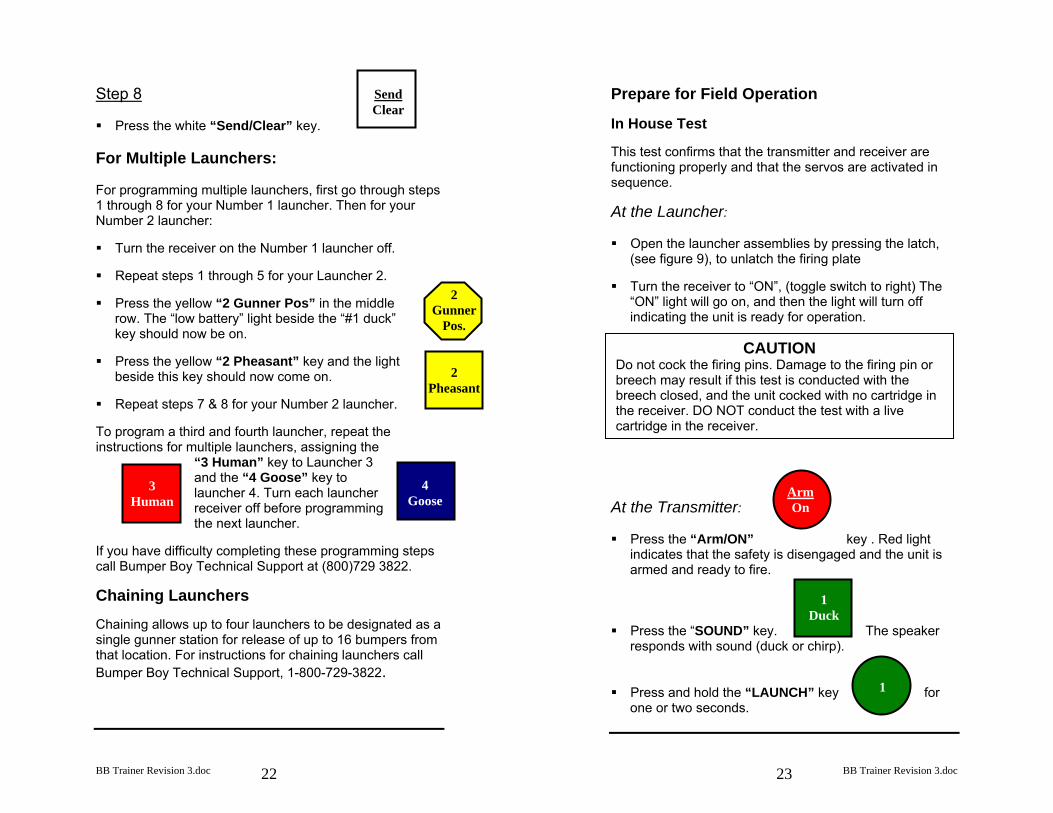
Step 8 Press the white “Send/Clear” key.
For Multiple Launchers: For programming multiple launchers, first go through steps 1 through 8 for your Number 1 launcher. Then for your Number 2 launcher: Turn the receiver on the Number 1 launcher off.
Repeat steps 1 through 5 for your Launcher 2.
Press the yellow “2 Gunner Pos” in the middle
row. The “low battery” light beside the “#1 duck” key should now be on.
Press the yellow “2 Pheasant” key and the light
beside this key should now come on. Repeat steps 7 & 8 for your Number 2 launcher.
To program a third and fourth launcher, repeat the instructions for multiple launchers, assigning the
“3 Human” key to Launcher 3 and the “4 Goose” key to launcher 4. Turn each launcher receiver off before programming the next launcher.
If you have difficulty completing these programming steps call Bumper Boy Technical Support at (800)729 3822. Chaining Launchers Chaining allows up to four launchers to be designated as a single gunner station for release of up to 16 bumpers from that location. For instructions for chaining launchers call Bumper Boy Technical Support, 1-800-729-3822.
2 Gunner
Pos.
2 Pheasant
BB Trainer Revision 3.doc
23
Arm On
1 Duck
1
Prepare for Field Operation In House Test This test confirms that the transmitter and receiver are functioning properly and that the servos are activated in sequence. At the Launcher: Open the launcher assemblies by pressing the latch,
(see figure 9), to unlatch the firing plate Turn the receiver to “ON”, (toggle switch to right) The
“ON” light will go on, and then the light will turn off indicating the unit is ready for operation.
At the Transmitter: Press the “Arm/ON” key . Red light
indicates that the safety is disengaged and the unit is armed and ready to fire.
Press the “SOUND” key. The speaker
responds with sound (duck or chirp). Press and hold the “LAUNCH” key for
one or two seconds.
CAUTION Do not cock the firing pins. Damage to the firing pin or breech may result if this test is conducted with the breech closed, and the unit cocked with no cartridge in the receiver. DO NOT conduct the test with a live cartridge in the receiver.
BB Trainer Revision 3.doc
24
1
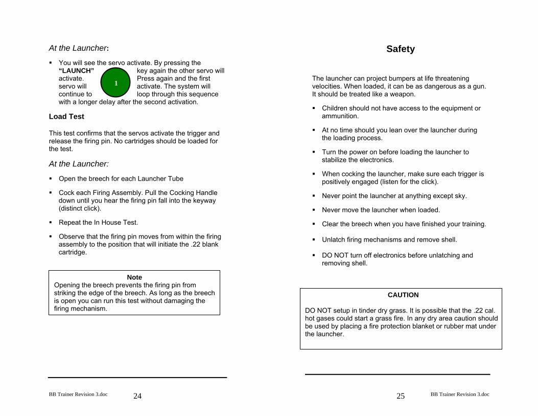
At the Launcher: You will see the servo activate. By pressing the
“LAUNCH” key again the other servo will activate. Press again and the first servo will activate. The system will continue to loop through this sequence with a longer delay after the second activation.
Load Test This test confirms that the servos activate the trigger and release the firing pin. No cartridges should be loaded for the test. At the Launcher: Open the breech for each Launcher Tube
Cock each Firing Assembly. Pull the Cocking Handle
down until you hear the firing pin fall into the keyway (distinct click).
Repeat the In House Test.
Observe that the firing pin moves from within the firing
assembly to the position that will initiate the .22 blank cartridge.
Note Opening the breech prevents the firing pin from striking the edge of the breech. As long as the breech is open you can run this test without damaging the firing mechanism.
BB Trainer Revision 3.doc
25
Safety
The launcher can project bumpers at life threatening velocities. When loaded, it can be as dangerous as a gun. It should be treated like a weapon. Children should not have access to the equipment or
ammunition. At no time should you lean over the launcher during
the loading process. Turn the power on before loading the launcher to
stabilize the electronics. When cocking the launcher, make sure each trigger is
positively engaged (listen for the click). Never point the launcher at anything except sky.
Never move the launcher when loaded.
Clear the breech when you have finished your training.
Unlatch firing mechanisms and remove shell.
DO NOT turn off electronics before unlatching and
removing shell.
CAUTION
DO NOT setup in tinder dry grass. It is possible that the .22 cal. hot gases could start a grass fire. In any dry area caution should be used by placing a fire protection blanket or rubber mat under the launcher.
BB Trainer Revision 3.doc
26
Operation in the Field
Your Bumper Boy is a flexible tool that will provide realistic training situations to prepare your dog for hunting and competition. The following step-by- step procedures will assist you to safely and effectively use the Bumper Boy in your training program.
Plan the Scenario Examine the terrain and choose the lines you wish to use to challenge your dog. Select the location for setting up the launcher, the area of fall for the bumper or Super Bird, and the location of the line from which you and your dog will run the scenario. Consider the effect wind may have on the path of the bumper and the dog’s performance.
CAUTION
Inspect the line your dog may run to the area of the fall for holes, hidden ditches or other obstacles that may injure your dog. Be sure there is no vegetation or other obstructions overhanging the location you have selected for the launcher or in the line of flight of the bumper.
Tip Run the In House Test, and check the sound function, the night before you plan to use your Bumper Boys. If you observe a low battery light on either the transmitter or the receivers, or the sound does not activate at the launcher, charge the batteries in those components.
CAUTION
Ensure the launcher is not set up on dry grass to avoid an accidental fire.
BB Trainer Revision 3.doc
27
Configure the Launcher (Bi-Directional Mode) The Ultra II Bumper Boy 2 and 4 shot models can be configured to launch the bumpers in one direction, or in opposite directions. The unit is shipped with all launcher tubes oriented in the same direction. To configure the unit to launch bumpers in opposite directions proceed as follows: Remove the three wing nuts and their associated
washers and lock washers. Remove the end plate.
Rotate the threaded angle adjustment rod(s) for the
removable launcher assemblies past the top of the frame or end plate, so they lie on the opposite side of the launcher frame when the end plate is replaced.
Pull the near Launcher Assembly(s) and the spacer
from the launcher frame. Rotate the Launcher Assembly(s) 180 degrees in a
horizontal plane. Replace the Launcher Assembly and the spacer on
the launcher frame
Replace the end plate and the washers and wing nuts.
Use the same method to return the launcher assemblies to the same direction.
CAUTION
Be sure the wires leading to the launcher tube servo are free to remain slack when the launch tube is rotated on the launcher frame and the launcher tube breech is opened.
BB Trainer Revision 3.doc
28
1
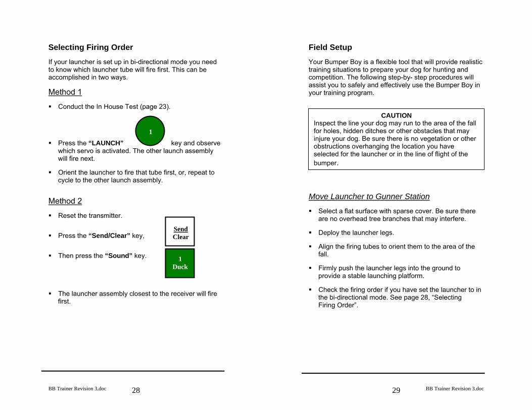
Selecting Firing Order If your launcher is set up in bi-directional mode you need to know which launcher tube will fire first. This can be accomplished in two ways. Method 1 Conduct the In House Test (page 23).
Press the “LAUNCH” key and observe
which servo is activated. The other launch assembly will fire next.
Orient the launcher to fire that tube first, or, repeat to
cycle to the other launch assembly. Method 2 Reset the transmitter.
Press the “Send/Clear” key,
Then press the “Sound” key.
The launcher assembly closest to the receiver will fire
first.
Send Clear
1 Duck
BB Trainer Revision 3.doc
29
Field Setup Your Bumper Boy is a flexible tool that will provide realistic training situations to prepare your dog for hunting and competition. The following step-by- step procedures will assist you to safely and effectively use the Bumper Boy in your training program.
Move Launcher to Gunner Station Select a flat surface with sparse cover. Be sure there
are no overhead tree branches that may interfere. Deploy the launcher legs.
Align the firing tubes to orient them to the area of the
fall. Firmly push the launcher legs into the ground to
provide a stable launching platform. Check the firing order if you have set the launcher to in
the bi-directional mode. See page 28, “Selecting Firing Order”.
CAUTION Inspect the line your dog may run to the area of the fall for holes, hidden ditches or other obstacles that may injure your dog. Be sure there is no vegetation or other obstructions overhanging the location you have selected for the launcher or in the line of flight of the bumper.
BB Trainer Revision 3.doc
30
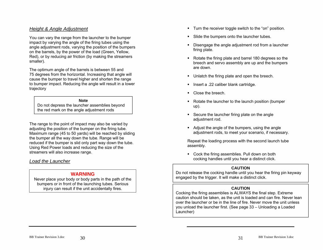
Height & Angle Adjustment You can vary the range from the launcher to the bumper impact by varying the angle of the firing tubes using the angle adjustment rods, varying the position of the bumpers on the barrels, by the power of the load (Green, Yellow, Red), or by reducing air friction (by making the streamers smaller). The optimum angle of the barrels is between 55 and 75 degrees from the horizontal. Increasing that angle will cause the bumper to travel higher and shorten the range to bumper impact. Reducing the angle will result in a lower trajectory
The range to the point of impact may also be varied by adjusting the position of the bumper on the firing tube. Maximum range (45 to 50 yards) will be reached by sliding the bumper all the way down the tube. Range will be reduced if the bumper is slid only part way down the tube. Using Red Power loads and reducing the size of the streamers will also increase range. Load the Launcher
Note Do not depress the launcher assemblies beyond the red mark on the angle adjustment rods
WARNING Never place your body or body parts in the path of the
bumpers or in front of the launching tubes. Serious injury can result if the unit accidentally fires.
BB Trainer Revision 3.doc
31
Turn the receiver toggle switch to the “on” position. Slide the bumpers onto the launcher tubes.
Disengage the angle adjustment rod from a launcher
firing plate. Rotate the firing plate and barrel 180 degrees so the
breech and servo assembly are up and the bumpers are down.
Unlatch the firing plate and open the breech.
Insert a .22 caliber blank cartridge.
Close the breech.
Rotate the launcher to the launch position (bumper
up). Secure the launcher firing plate on the angle
adjustment rod. Adjust the angle of the bumpers, using the angle
adjustment rods, to meet your scenario, if necessary. Repeat the loading process with the second launch tube assembly. Cock the firing assemblies. Pull down on both
cocking handles until you hear a distinct click.
CAUTION Do not release the cocking handle until you hear the firing pin keyway engaged by the trigger. It will make a distinct click.
CAUTION Cocking the firing assemblies is ALWAYS the final step. Extreme caution should be taken, as the unit is loaded and can fire. Never lean over the launcher or be in the line of fire. Never move the unit unless you unload the launcher first. (See page 33 – Unloading a Loaded Launcher)
BB Trainer Revision 3.doc
32
Arm On
1 Duck
1
1 Duck
1
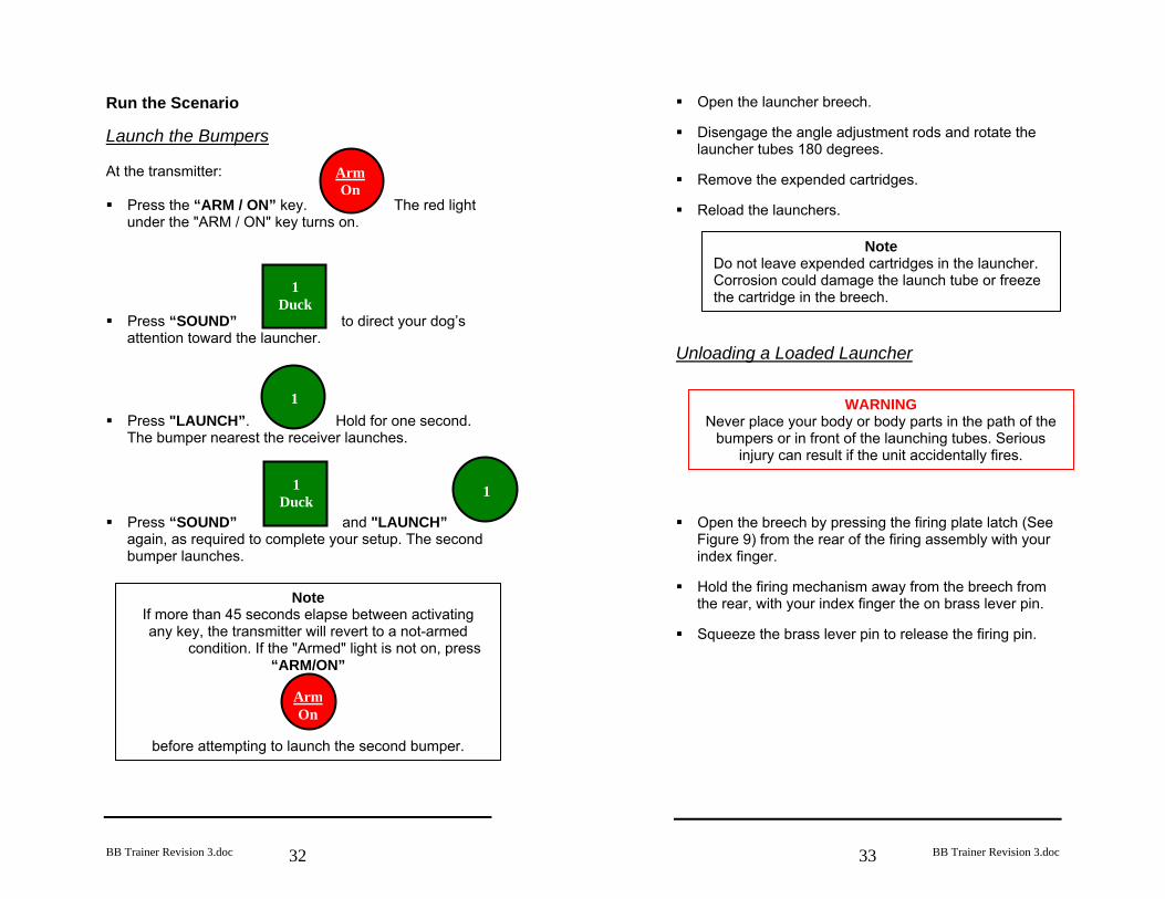
Note If more than 45 seconds elapse between activating any key, the transmitter will revert to a not-armed
condition. If the "Armed" light is not on, press “ARM/ON”
Arm On
before attempting to launch the second bumper.
Run the Scenario Launch the Bumpers At the transmitter: Press the “ARM / ON” key. The red light
under the "ARM / ON" key turns on. Press “SOUND” to direct your dog’s
attention toward the launcher. Press "LAUNCH”. Hold for one second.
The bumper nearest the receiver launches. Press “SOUND” and "LAUNCH”
again, as required to complete your setup. The second bumper launches.
BB Trainer Revision 3.doc
33
Open the launcher breech. Disengage the angle adjustment rods and rotate the
launcher tubes 180 degrees. Remove the expended cartridges.
Reload the launchers.
Unloading a Loaded Launcher
Open the breech by pressing the firing plate latch (See
Figure 9) from the rear of the firing assembly with your index finger.
Hold the firing mechanism away from the breech from
the rear, with your index finger the on brass lever pin. Squeeze the brass lever pin to release the firing pin.
Note Do not leave expended cartridges in the launcher. Corrosion could damage the launch tube or freeze the cartridge in the breech.
WARNING Never place your body or body parts in the path of the
bumpers or in front of the launching tubes. Serious injury can result if the unit accidentally fires.
BB Trainer Revision 3.doc
34
Disengage the angle adjustment rod from the firing tube base.
Rotate the launcher tubes and bumpers to the breech
up position. Remove the cartridges.
Wet Weather Training The transmitter and receiver are water resistant and can be used in all weather conditions. If immersed, dry thoroughly before attempting to use the system. During continued water-work, the inside of the Bumper tube should be dry. If the tube is wet, a loss of power may occur. Drying can be accomplished by spinning the Bumper by the power handle and throw rope, by using a drying rack to let the water drain out, or by using a shotgun brush with a cloth or shammy material wrapped around it. Ensuring the “O” rings on the launcher assemblies are properly greased will also help.
Fire Warning
In dry conditions, hot gases from the .22 cal shell could cause a grass fire. ALWAYS use a rubber mat or fire
blanket under the launcher.
BB Trainer Revision 3.doc
35
Bumper Boy Maintenance
Bumper Care Keep the bumpers clean. Clear accumulated grit and carbon from the bumper barrel with a 12-gauge shotgun soft cleaning tip. DO NOT oil the barrels. Launcher Care Keep launcher components clean. Check to insure the nuts securing the launcher frame components are secure. Periodically (every three to six months) clean accumulated carbon and grit from the launcher tube barrel with a .22 caliber cleaning rod and cleaning patch soaked in light oil. Clean the exterior of the launcher tube. Apply silicone grease to the “O” rings on the launcher tubes monthly. Worn “O” rings can be purchased at most automotive stores. Part # N70113 Size - 9/16th. Use “Dry Graphite” lubricant to lubricate the firing assemblies every three months. Introduce the graphite lubricant through into the firing pin hole, with the firing pin in the cocked position and on both sides of the lever arm where it is held by the bracket integral to the launcher assembly. Transmitter and Receiver Care Store in a dry environment. Recharge the batteries after several days of use.
BB Trainer Revision 3.doc
36
Armed (caution)
Low Batt.
Armed (caution)
Trouble Shooting Guide
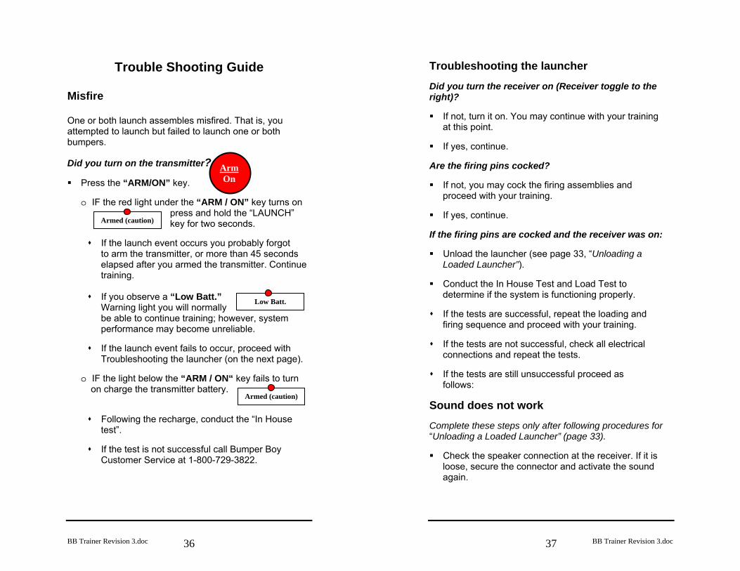
Misfire One or both launch assembles misfired. That is, you attempted to launch but failed to launch one or both bumpers. Did you turn on the transmitter? Press the “ARM/ON” key.
o IF the red light under the “ARM / ON” key turns on
press and hold the “LAUNCH” key for two seconds.
If the launch event occurs you probably forgot
to arm the transmitter, or more than 45 seconds elapsed after you armed the transmitter. Continue training. If you observe a “Low Batt.”
Warning light you will normally be able to continue training; however, system performance may become unreliable.
If the launch event fails to occur, proceed with
Troubleshooting the launcher (on the next page).
o IF the light below the “ARM / ON“ key fails to turn on charge the transmitter battery.
Following the recharge, conduct the “In House test”.
If the test is not successful call Bumper Boy
Customer Service at 1-800-729-3822.
Arm On
BB Trainer Revision 3.doc
37
Troubleshooting the launcher Did you turn the receiver on (Receiver toggle to the right)? If not, turn it on. You may continue with your training
at this point. If yes, continue.
Are the firing pins cocked? If not, you may cock the firing assemblies and
proceed with your training. If yes, continue.
If the firing pins are cocked and the receiver was on: Unload the launcher (see page 33, “Unloading a
Loaded Launcher”). Conduct the In House Test and Load Test to
determine if the system is functioning properly. If the tests are successful, repeat the loading and
firing sequence and proceed with your training. If the tests are not successful, check all electrical
connections and repeat the tests. If the tests are still unsuccessful proceed as
follows: Sound does not work Complete these steps only after following procedures for “Unloading a Loaded Launcher” (page 33). Check the speaker connection at the receiver. If it is
loose, secure the connector and activate the sound again.
BB Trainer Revision 3.doc
38
If the sound still does not work, press the sound key and check to see if the “Low Battery” warning light comes on at the receiver. When the receiver detects a low battery condition, it will turn off the sound system. Recharge the receiver battery.
If the sound still does not work call Bumper Boy
Customer Service at 1-800-729-3822. Servo operates, but does not fire consistently Complete these steps only after following procedures for Unloading a Loaded Launcher” (page 33). Lubricate the Firing Assembly See page 35,
“Launcher Care”. Check for free movement of the lever arm by
squeezing the brass lever arm pin against the firing assembly. If it does not move easily in and out of the bracket holding it to the firing assembly loosen the lever bolt and nut. The lever bolt should turn freely within the bracket but should not be move noticeably up and down.
Check the launcher wiring harness and receiver
connector. If the connector is loose, secure it in its connector. If the harness is damaged call Bumper Boy Customer Service at 1-800-729-3822.
Check servo arm alignment. If it does not re-align as
shown in Figure 9 replace the servo. Conduct the In House Test. If the test is still not
consistently successful call Bumper Boy Customer Service at 1-800-729-3822.
BB Trainer Revision 3.doc
39
Firing pin will not cock Complete these steps only after following procedures for “Unloading a Loaded Launcher” (page 33). Lever cannot return because the servo arm is
touching the lever pin and is not returning to the correct alignment. Replace the servo.
Check for free movement of the lever arm by
squeezing the brass lever arm pin against the firing assembly. If it does not move easily in and out of the bracket holding it to the firing assembly loosen the lever bolt and nut. The lever bolt should turn freely within the bracket but should not move noticeably up and down.
Lubricate the Firing Assembly See page 35,
“Launcher Care”. Replacing a Servo Complete these steps only after following procedures for “Unloading a Loaded Launcher” (page 33). If a servo motor needs to be replaced, they can be purchased locally from many hobby stores or directly from Bumper Boy at 1-800-729-3822. Servo type is any compatible GWS series. Cut heat shrink open at servo connector – located
about 11 inches back from servo Pull apart wiring harness from connector
Remove all four servo mounting screws and retain
for mounting the new servo.
BB Trainer Revision 3.doc
40
Note the orientation of the servo in the “L” shaped bracket under the servo. Remove the faulty servo.
Remove screw that secures the servo arm to the
faulty servo. Set the screw, servo arm and the mounting bracket from the top of the faulty servo aside for mounting the new servo.
Install the mounting bracket and servo arm on the
new servo. The servo arm should be aligned so that the Arm will be on the right side of the brass lever pin, (looking past the receiver to the lever pin), but not past the either edge of the servo. Observe the orientation of the lever arm on another launcher assembly for comparison.
Re-install the servo mounting screws. Use caution
not to over tighten the screws. Plug new servo into wiring harness. Put new heat
shrink tubing on wiring harness, match wiring harness colors, and press connector together.
Test servo by turning the receiver toggle switch to
PROGRAM. This sets the servo. If servo does not activate, reverse the connector. It should move back and forth slightly but remain in the position described above. If it does not, remove the servo arm screw, re-orient the servo arm, and replace the servo arm screw. Now turn the receiver toggle switch to OFF, then back to PROGRAM. The servo arm should flicker and remain in the position. If it does not, call Bumper Boy Customer Service at 1-800-729-3822.
Apply hot glue on plug, cover with the heat shrink
tubing, and shrink with a hot air gun, blow dryer, or lighter. Re-install wire ties to secure the wiring harness.
Thank you for purchasing the Bumper Boy Retriever Trainer
Customer Service 1-800-729-3822