Embed Size (px)
Citation preview

GB
798666.HO.GB0 Technical changes reserved.
07.2013 / AA
© 2013 Honeywell International Inc.
Operation Instruction
VARIODYN® D1 Comprio

Operation Instruction VARIODYN® D1 Comprio
2 FB 798666.HO.GB0 / 07.13
Intended use This product may only be used for the applications outlined in the catalogue and the technical description and in combination with external devices and components which have been recommended or approved by us. Warning
To ensure correct and safe operation of the product, all instructions concerning its proper transport, storage, installation and mounting must be observed and it must be operated with care. Safety-relevant user information
This instruction includes all information required for the intended use of the products described.
The term “qualified personnel” in the context of the safety information included in this instruction or on the product itself means:
• project planning personnel that are familiar with the safety guidelines concerning fire alarm and extinguishing systems.
• maintenance personnel that have been instructed in the operation of the components of fire alarm and extinguishing systems and are familiar with the information on their operation as included in this instruction.
• trained installation and service personnel with the necessary qualification for carrying out repairs on such components of fire alarm and extinguishing systems or who are authorised to commission, ground and label electrical circuits and devices/systems according to the standards of security technology.
Safety warnings
The following information is given in the interest of your personal safety and to prevent damage to the product described in this instruction and all devices connected to it. Safety information and warnings to prevent hazards to life and health of users or maintenance personnel and to prevent damage to property are marked by the symbols defined below. Within the context of this instruction, these symbols have the following meaning:
Indicates that serious or fatal injuries or considerable property damage might result if the specified precautions are not complied with.
Draws particular attention to important information about the product or a part of the instruction.
Dismantling
In accordance with Directive 2002/96/EC (WEEE), the electrical and electronic equipment can be returned to the manufacturer for proper disposal after it has been dismantled.

Operation Instruction VARIODYN® D1 Comprio
FB 798666.HO.GB0 / 07.13 3
1 General / Application .................................................................................................................................................. 4
1.1 Responsibility of the Operator ............................................................................................................................. 5 1.2 Associated Documents ....................................................................................................................................... 5
2 Display and Operating Elements .............................................................................................................................. 6
2.1 VARIODYN D1 Comprio ................................................................................................................................... 6 ®
2.2 Power Amplifiers (PA) 4XD Series ................................................................................................................... 17 3 Maintenance and Installation ................................................................................................................................... 19
4 Service / Maintenance Contact Information ........................................................................................................... 20

Operation Instruction VARIODYN® D1 Comprio
4 FB 798666.HO.GB0 / 07.13
1 General / Application Thank you very much for choosing VARIODYN® D1. An emergency audio warning system or a voice alarm system as defined by the standards DIN VDE 0833-4 and TRVB S 158 must consist of components that satisfy the standards of the series DIN EN 54. It must be ensured that these components interact together in a manner appropriate to the function. Devices for use in demanding ambient conditions, such as cold stores, galvanising plants or corrosive atmospheres, must be suitable for this particular application or must be adapted using suitable protective measures.
Designation of the system depending on the region of use Depending on the location of use (country, applicable standard), the system is designated as either an emergency audio warning system (AWS) or a voice alarm system (VAS).
In the interests of readability, only the term “voice alarm system” is used in the following chapters.
D Voice alarm systems (VAS) according to DIN VDE 0833-4 and EN 54
A Emergency audio warning system (AWS) according to TRVB S 158 A voice alarm system can be used for issuing alarms anywhere that hazards to people can be expected. Voice alarms are particularly effective in buildings and rooms frequented by visitors or other people who are not trained how to act in an emergency or where visual signal devices cannot always be clearly recognised. An especially high level of risk exists in the case of people who are dependent on external help in an emergency, such when evacuation of the building is necessary. This may include people who are ill, the elderly and children. The voice alarm system is mainly used in combination with a fire alarm control panel for emitting alarms. In practice, the voice alarm system is also used for tasks outside of this area of application. Typical examples of this include spoken messages such as advertising or calling people in airports, announcements at train stations or playing background music. Different requirements are placed on the voice alarm system depending on this combined use as an alarm and as a general public address system. For example, external loudspeakers which can generate a high volume level are required for voice alarms. At the same time, however, it should be possible to transmit a high-quality music signal in other areas and ideally also to control the volume for individual areas. The requirements for the areas of safety, comfort and flexibility demand a high level of specialised skill for the planning and implementation of a system as well as very good knowledge of individual product components. The VARIODYN®
D1 system is assembled at the factory as a modularly expandable version with various components according to the specific building requirements. This means that special solutions can be implemented economically and effectively for buildings of different sizes and for various alarm tasks.

Operation Instruction VARIODYN® D1 Comprio
FB 798666.HO.GB0 / 07.13 5
1.1 Responsibility of the Operator In addition to the standard-compliant design, a definition of the minimum requirements and functions between the operator of the system and the responsible authorities is needed for the setup and operation of a voice alarm system. The standard TRVB S 158 applies in Austria (AWS) and the standard DIN VDE 0833 in Germany (VAS) if the system is controlled automatically by a fire alarm control panel.
Basic stipulations
Definition of the safety level (I, II, III)
Scope of public address system
Alarm areas, detection areas, fire sections
Site of the voice alarm control panel (VACP), configuration levels and accessibility
Need for fire microphones and number of terminals, as well as their usability
Alarm organisation and stipulation of the announcement texts 1.2 Associated Documents These instructions contain all important information for operation of VARIODYN® systems. Additional information on assembly, installation, start-up and configuration can be found in the following documents:
Part No. Name
798661.GB0 Planning Principles for Voice Alarm Systems
798667.HO.GB0 Installation Instruction VARIODYN® D1 Comprio
798664.HO.GB0 Commissioning Instruction VARIODYN® D1 and VARIODYN® D1 Comprio
798665.HO Installation Instructions Loop Isolator Module (LIM)
Additional and updated Informations
The described features, specifications and product related informations in this manual correspond to the date of issue (refer to date on the front page) and may differ due to modifications and/or amended Standards and Regulations of the System design, Installation and Commissioning. Updated documentations, informations and declaration of conformity are available for comparison on the www.esser-systems.de and www.hls-austria.com homepage.

Operation Instruction VARIODYN® D1 Comprio
6 FB 798666.HO.GB0 / 07.13
2 Display and Operating Elements
2.1 VARIODYN® D1 Comprio
The functions of the VARIODYN® D1 individual components are collected together in the compact control unit. A control unit consists of a digital output module (DOM), a universal interface module (UIM) with a reduced number of control contacts, a view control module (VCM) and an integrated voice input station with 12 programmable buttons. The final amplifier as well as the loudspeaker, for example, is connected to the control unit. A control unit offers interfaces to all input/output modules and also manages and monitors the loudspeaker circuits. Other components of the VARIODYN® D1 system can also be optionally used. The standards-compliant display of collective messages as well as operation and monitoring take place using the four integrated buttons / LEDs. The control unit is configured via the programming and service software Designer D1. The interface module of the VARIODYN® D1 Comprio offers two analogue, potential-free audio inputs, one analogue, potential-free audio output and 12 control contacts. In addition to external call stations of the DAL bus, a hand microphone can be connected to the front side and fastened in the corresponding holder.
3
4
1
2
Fig. 1: Front view (here: control unit 4-24)
Voice input station
Display and operation of collective messages
Interface module for connecting external analogue audio signals
Control unit

Operation Instruction VARIODYN® D1 Comprio
FB 798666.HO.GB0 / 07.13 7
Voice input station
The buttons of the terminal are freely programmable. The desired function is programmed in the system configuration by the installer with features specific to the building and customer. The buttons of the terminal can be used to start announcements or execute system functions. Corresponding label sheets are included for labelling of the buttons.
1
2
3
Operating buttons (= 12 buttons freely configurable)
Holder for hand microphone and speaker, e.g. for prelistening to saved messages or intercom conversations (two-way, asynchronous communication).
Microphone jack for hand microphone with built-in loudspeaker and audible microphone monitoring
Depending on the programming, the corresponding button must be pressed during the announcement. Alternatively, the function of the button is activated when pressed and deactivated when pressed again (toggle function).
LED off
LED on
LED flashing
Function not active e.g. preselection active or announcement running
e.g. speaking not possible (occupied)

Operation Instruction VARIODYN® D1 Comprio
8 FB 798666.HO.GB0 / 07.13
Example of function key assignment
Circuit 1
Pre-selection of circuit 1 (button with toggle function) Selects circuit 1 (or multiple circuits, if programmed), which can be used as the target of an announcement.
Circuit 2
Pre-selection of circuit 2 (button with toggle function) As described above, except circuit 2
Announcement
Announcement / speak (keep button held pressed) Starts an announcement to the preselected circuits. If a gong has been programmed as an attention signal for the announcement, it is only possible to speak after this signal has finished.
Musikon / off
Music on / off (button with toggle function) Switches the background music on/off. The music can be played from an external CD player or other audio source (via the available audio inputs of the DCS, UIM or via digital audio data of the SCU).
IntercomDCS 2
Intercom DCS 2: (keep button held pressed) Establishes an intercom connection to another terminal. Communication takes place using the microphone and built-in speaker.
Fireannouncement
Fire announcement (button with toggle function) Pressing the button starts a previously saved fire announcement for the assigned loudspeaker circuits (areas).
Toggle function Press once = ON Press again = OFF
Detailed information on this topic can be found in the Commissioning Instruction (Part No. 798667.HO.GB0). The button labelling can be created on a project-specific basis. The labels are laid in the button recesses and held in place with the covers.

Operation Instruction VARIODYN® D1 Comprio
FB 798666.HO.GB0 / 07.13 9
Display and operation of collective messages
The display and operation of standards-compliant collective messages is possible. These are displayed audibly via the integrated buzzer and visibly via the LEDs. Using the 4 operating buttons, it is possible to switch off or mute messages or perform a lamp test of the system.
1
2
3
Fig. 2: Display and operation of collective messages
LED display for collective messages Faults�of the voice alarm system are displayed here. The indication takes place via the LED (yellow / red) and the integrated buzzer for audible signalling of faults.
COMMON ALARM ON button The red button starts an evacuation message throughout the entire system. The LED "ALERT MESSAGE" lights up and the buzzer is activated. COMMON ALARM OFF button This button ends a previously started evacuation message. The LED "ALERT MESSAGE" goes out and the buzzer is deactivated. ALARM BUZZER OFF button This button switches off the buzzer for a previously started evacuation message. The LED "ALERT MESSAGE" does not go out. LAMP TEST button This button performs a lamp and buzzer test. The test is only active for as long as the button is pressed.
Integrated buzzer for audible signalling of faults. COMMON TROUBLE
OFF Normal operation - No collective faults
Flashing yellow, with alarm sound
A collective fault exists The buzzer is switched off with the button "MONITOR" in the control unit.
ALERT MESSAGE
OFF Normal operation - No alarm state
Flashing red, edwith alarm sound
The system is in an alarm state. The buzzer is switched off with the button "ALARM BUZZER OFF".
SYS FAULT
OFF Normal operation - no faults
Flashing yellow, with alarm sound
A fault exists The buzzer is switched off after correction of the fault.
Operation Instruction VARIODYN® D1 Comprio
10 FB 798666.HO.GB0 / 07.13
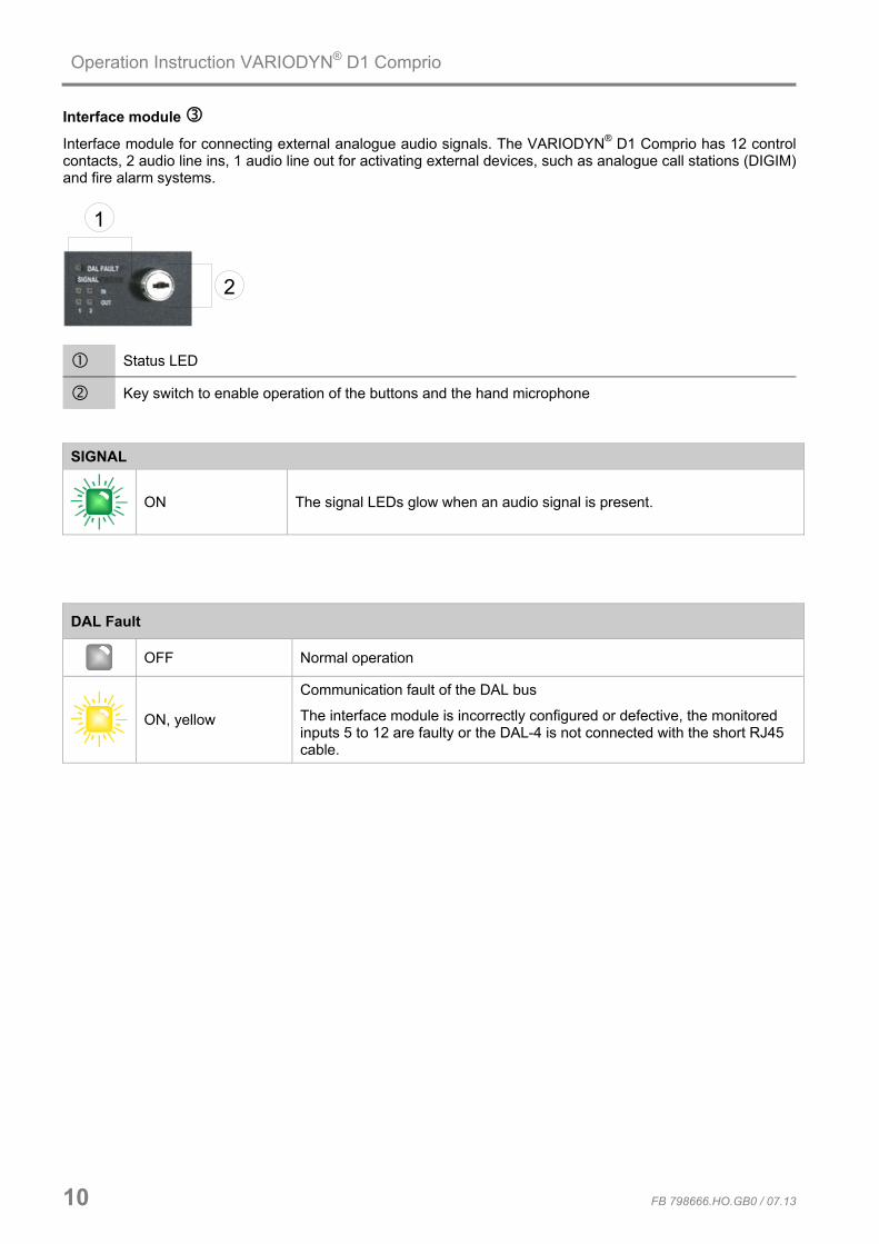
Interface module
Interface module for connecting external analogue audio signals. The VARIODYN® D1 Comprio has 12 control contacts, 2 audio line ins, 1 audio line out for activating external devices, such as analogue call stations (DIGIM) and fire alarm systems.
1
2
Status LED
Key switch to enable operation of the buttons and the hand microphone SIGNAL
ON The signal LEDs glow when an audio signal is present.
DAL Fault
OFF Normal operation
ON, yellow
Communication fault of the DAL bus
The interface module is incorrectly configured or defective, the monitored inputs 5 to 12 are faulty or the DAL-4 is not connected with the short RJ45 cable.

Operation Instruction VARIODYN® D1 Comprio
Control unit
4
1 2 3 5 6
LED indicators of control contacts 1-8
LED indicators of the audio outputs 1-4 (amplifier channels), LINE RELAY and LINE ERROR
LED indicators of the DAL connections
Collective LED indicators for : Power Error Stand-alone operation Powersave
Monitor button
Buzzer/sounder
LED indicators for the control contacts
The status of control contacts 1-8 is indicated with these LED.
1 2 3 4 5 6 7 8
CONTACTS
Fig. 3: LED of the CONTACTS (example)
OFF Control contact not activated
ON, green Control contact activated
FB 798666.HO.GB0 / 07.13 11

Operation Instruction VARIODYN® D1 Comprio
12 FB 798666.HO.GB0 / 07.13
LED indicators – Status of an amplifier channel The functioning of the amplifiers is constantly monitored. The result of this check is indicated by the LEDs of the amplifier channels CHANNEL 1 and 2 (see Fig. 4). The following status indications are possible:
CHANNEL 1
1 2 3 4 5 6
Fig.4: LED of amplifier CHANNEL 1 (example)
OFF 100 V amplifier channel not in use
ON, green 100 V amplifier channel connected and ready for operation
Flashing green 100 V amplifier channel currently prelistened
ON, yellow 100 V fault - amplifier channel defective
ON, red Alarm connection for amplifier channel active (indication depends on the
hardware model)

Operation Instruction VARIODYN® D1 Comprio
FB 798666.HO.GB0 / 07.13 13
LED indicators of the LINE RELAY If a loudspeaker circuit is currently in use by e.g. an announcement, this is indicated by the corresponding LED. A separate relay (LINE RELAY) for each loudspeaker line is used for this with object-specific programming. The LINE RELAY LEDs indicate which loudspeaker lines are active.
1 2 3 4 5 6
CHANNEL 1
Fig. 5: LED of the LINE RELAY LED LINE RELAY for amplifier channels 1 - 6
OFF 100 V loudspeaker circuit not in use
ON, green 100 V loudspeaker circuit in use
LED indicators of the LINE ERROR Depending on the system configuration, every loudspeaker circuit is constantly monitored for short-circuit, earth fault, impedance deviation and interruption. In event of a fault in the loudspeaker circuit, the associated LED glows yellow. In event of a short circuit, the loudspeaker line is no longer connected until the error is corrected. In event of the other faults, the loudspeaker line continues to remain available for announcements.
1 2 3 4 5 6
CHANNEL 1
Fig. 6: LED of the LINE ERROR LED LINE ERROR for amplifier channels 1 - 6
OFF Normal operation
ON, yellow Fault Short-circuit, earth fault, interruption or impedance deviation

Operation Instruction VARIODYN® D1 Comprio
14 FB 798666.HO.GB0 / 07.13
LED indicator for the DAL BUS Digital call stations (DCS) or Universal Interface Modules (UIM) can be connected to the three digital audio links (DAL). The 4th DAL is used for internal connections. The modules are controlled via the DAL BUS and are supplied with 24 V operating voltage.
1 2 3 4
DAL
Fig. 7: LED of the DAL BUS DAL Bus
OFF No device configured
ON, green Device connected and ready for operation
ON, yellow Device not connected, faulty or microphone defective. If a UIM is present or the
connection of the monitored inputs is faulty.
Flashing green Device being prelistened
LED indicators of the DAL channel The LEDs indicate which channel of the DAL Bus is being listened to over the integrated loudspeaker of the control module (see >Monitor< button).
1 2
IN
OUT
DAL
Fig. 8: LED of the DAL channel DAL channel
OFF Prelistening not activated
Flashing green Prelistening activated

Operation Instruction VARIODYN® D1 Comprio
Collective LED indicators These LED indicators show the general status of the control module.
ERROR POWER
FB 798666.HO.GB0 / 07.13 15
STANDALONE POWERFAIL
MONITOR
Fig. 9: Common displays ERROR / Acknowledge error message
OFF Normal operation
Flashing yellow, with alarm sound
The integrated buzzer can be acknowledged by pressing the >Monitor< button. The ERROR LED changes from flashing to steady glowing. The buzzer is triggered upon the next error message.
ON, yellow Fault acknowledged. However, the fault is still present.
POWER
OFF No operating voltage
ON, green Operating voltage present, device active

Operation Instruction VARIODYN® D1 Comprio
16 FB 798666.HO.GB0 / 07.13
STANDALONE
OFF Networking
ON, yellow No networking = Stand-alone operation
POWERFAIL
OFF Normal operation
ON, yellow One of the energy supplies (power supply or emergency power) is faulty
Monitor button
The buzzer can be switched off by pressing the button. To check whether an audio signal is currently present on an amplifier or DAL channel, the audio inputs and outputs on the control unit can be prelistened to via the integrated speaker using the monitor button. Pressing the button repeatedly will run through the individual listening points. The current listening point is indicated by the green flashing LED of the corresponding amplifier channel. Pre listening is automatically ended after a preset time (180 seconds: factory setting) or can be manually ended by a long press of the monitor button.
MONITOR
• Upon acknowledging of the buzzer, only the acoustic warning signal is temporarily deactivated. • Resetting of the alarm and fault messages is only possible after correcting of the fault cause and
may only be performed by a qualified technician.

Operation Instruction VARIODYN® D1 Comprio
FB 798666.HO.GB0 / 07.13 17
2.2 Power Amplifiers (PA) 4XD Series The power amplifiers (PA) serve to amplify the voice/audio signal. Amplifiers are connected to the control module and also controlled via the control module. The amplifier as well as the cabling is constantly monitored depending on the configuration.
ERROR
CLIP
CHANNEL
LOW
1
HIGH
POWER
BATT POWER
CPU STATUS
SYS FAULT
MAINS POWER
32 4
Fig. 10: Front view of power amplifier 4XD125B ERROR CHANNEL 1 - 4
OFF Normal operation
ON, yellow Fault or overload of the respective amplifier channel
CLIP CHANNEL 1 - 4
OFF Level control of the amplifier channel in the normal range
ON, yellow Amplifier channel is operating at its limits (e.g. 0.5 dB under full load or signal
level too high - higher amplifier power may be required).
With the two LEDs for “High” and “Low” channel, the range of the detected audio signal level can be displayed With the factory setting, the range is set to -20 dB (low) to -6 dB (high). The setting is configured via the DIL switches on the back side of the amplifier. HIGH CHANNEL 1 - 4
ON, green The detected level of the audio signal is -3 dB or -6 dB below the expected
nominal level for the high signal. The setting is configured via the DIP switch.
LOW CHANNEL 1 - 4
ON, green The detected level of the audio signal is -6 dB or -20 dB below the expected
nominal level for the low signal. The setting is configured via the DIP switch.

Operation Instruction VARIODYN® D1 Comprio
18 FB 798666.HO.GB0 / 07.13
POWER CHANNEL 1 - 4
OFF Amplifier final stages switched off
ON, green Normal operation
SYS FAULT
OFF No error present
ON, yellow System fault of the amplifier
BATT POWER
OFF Normal operation
ON, yellow Emergency power operation (amplifier is supplied by the battery)
MAINS POWER
OFF No 230 V operating voltage present
ON, green Normal operation
CPU STATUS
OFF CPU error (operating software without function)
Flashing green CPU OK (normal operation)
After the amplifier has booted up, the LED SYS FAULT, BATT POWER, MAINS POWER or CPU STATUS light up for 4 seconds in a specific combination.

Operation Instruction VARIODYN® D1 Comprio
FB 798666.HO.GB0 / 07.13 19
3 Maintenance and Installation Operation and maintenance of hazard warning systems (HWS) Requirements as per VdS guidelines and VDE 0833-1 and 2: The operator of the HWS must have received proper training or must have the work performed by someone who has received proper training. The operator or the person he/she commissions must take responsibility for ensuring that inspections are carried out when there are signs that the constant readiness of the system may have been impaired, in event of irregularities in the functioning of the system and in cases of alterations (e.g. in the use or design of the room) that may influence the monitoring tasks of the HWS. All necessary maintenance and alteration work on the HWS must be carried out immediately by the operator or the trained person who he/she commissions. HWS must be regularly serviced by an electrician. If there are faults, the HWS must be immediately inspected and corrected by an electrician.
Inspections Perform inspections according to VDE 0833-1 at least four times per year at roughly equal intervals.
Repairs Must be carried out immediately if it is confirmed during an inspection that there unauthorised deviations from the nominal conditions of the HWS.
Maintenance work Perform maintenance work according to the manufacturer instructions, however no less than once per year. This includes, for example: maintenance of system parts, replacing elements with limited service life (e.g. light bulbs), alignment, setting and adjusting of components and devices. The specifically required annual maintenance work may be performed along with the quarterly inspections. In addition, the HWS must be inspected every five years to ensure that it fulfils all requirements of this standard..
Regular tests In principle, the statutory standards, regulations and local requirements apply for the maintenance of the voice alarm system. However, these may be restricted by the manufacturer's specifications. For example, the manufacturer may stipulate that the maintenance intervals or replacement cycles of the devices must be shorter than required by law.
• Regular tests must be carried out to ensure that there is not and will not be any restriction on the emission of sound from the loudspeakers or on their function
• Regular tests must be carried out to check whether rooms excluded from the public address system in the planning documents now need to be included in the public address system.
• Regular tests must be carried out to ensure that when the voice alarm system or even one of the individual parts of the voice alarm system is switched off or malfunctions there is a suitable backup measure available (e.g. security personnel with megaphones etc.).
• Loudspeaker testing must be carried out at least once per year using suitable audio tests. If there is any doubt, a measurement must be carried out to prove the speech comprehensibility.
• In accordance with EN 60849, a maintenance contract must be concluded.
• Maintenance work must be carried out in accordance with DIN VDE 0833-4 or TRVB S 158.
• All events such as fault / replacement / maintenance / calibration of the VAS must be documented in a log book (Part No. 798671).
• The operating log must be stored near the system (or on the operator's premises).
Important information After an interruption of the power supply due to maintenance or if call stations are relocated during maintenance, the proper functioning of each individual call station must be checked. The fire department / evacuation call stations in particular must be checked by executing relevant functions as well as performing a “test announcement”.
Operation Instruction VARIODYN® D1 Comprio
20 FB 798666.HO.GB0 / 07.13
4 Service / Maintenance Contact Information The following service / maintenance contract information as well as important contact persons should be recorded. Service / maintenance personnel
Maintenance contract :______________________(No.) ________________________from:________________
Company : ______________________________________________________________________
______________________________________________________________________
______________________________________________________________________
Contact person : ______________________________________________________________________
Address : ______________________________________________________________________
______________________________________________________________________
Phone : ______________________________________________________________________
Mobile phone : ______________________________________________________________________
Fax : ______________________________________________________________________
E-mail : ______________________________________________________________________
In case of an incident, contact:
Contact person : ______________________________________________________________________
Function : ______________________________________________________________________
Address : ______________________________________________________________________
______________________________________________________________________
Phone : ______________________________________________________________________
Mobile phone : ______________________________________________________________________
Fax : ______________________________________________________________________
E-mail : ______________________________________________________________________
Remarks ______________________________________________________________________
______________________________________________________________________
______________________________________________________________________
______________________________________________________________________
______________________________________________________________________
______________________________________________________________________
Operation Instruction VARIODYN® D1 Comprio
Notes
FB 798666.HO.GB0 / 07.13 21

Operation Instruction VARIODYN D1 Comprio ®
Notes
22 FB 798666.HO.GB0 / 07.13

Operation Instruction VARIODYN® D1 Comprio
Notes
FB 798666.HO.GB0 / 07.13 23

Novar GmbH a Honeywell Company Dieselstraße 2 D-41469 Neuss Tel.: +49 (0) 21 37/17-0 (Verwaltung) Tel.: +49 (0) 21 37/17-600 (Kundenbetreuungscenter) Fax: +49 (0) 21 37/17-286 Internet: www.esser-systems.de E-Mail: [email protected]
HLS Austria GmbH Lemböckgasse 49 A-1230 Wien Tel.: +43 (0)1/600 60 30 Fax: +43 (0)1/600 60 30-900 Internet: www.hls-austria.com E-Mail: [email protected]