Embed Size (px)
Citation preview
CEI Enterprises, Inc. | 245 Woodward Rd SE | Albuquerque, NM 87102 | 800.545.4034 | ceienterprises.com
Asphalt Unloading PumpOperation & Maintenance Manual
CEI Service & Parts: 800.545.4034
For worldwide parts & service support, call CEI Enterprises: 800.545.4034
For Service & Parts Support
Service
Parts
Training
CEI maintains a fully-staffed service department, with factory-trained service technicians based across the United States for the fastest possible response to your service needs. For service work, including installation, startup, preventive maintenance and retrofits, contact the CEI Service Dept at 800.545.4034.
CEI Enterprises has one of the largest spare parts warehouses in the asphalt industry, stocked with parts for not only CEI products, but parts for competitors products as well. Moreover, our parts representatives have a more comprehensive knowledge of the parts and components used on your CEI equipment than anyone... anywhere. Based near interstates I-40 and I-25, as well as the nearby Albuquerque International Airport, we are conveniently located to rapidly ship parts nationwide and internationally. For your parts needs, contact the CEI Parts Dept at 800.545.4034.
CEI offers annual service training at our facility in Albuquerque, New Mexico. Hands-on instruction is provided by our factory-trained service technicians, merely steps away from where your CEI equipment was designed and built. Sessions are typically held in January and February, during the winter off season. Our Service Training Seminars provide the highest quality training available on maintaining your CEI equipment in top working order. For owners and operators of asphalt plants large and small, this is an invaluable investment in the knowledge & experience of your crew. For more information, please visit our website at ceienterprises.com.
CEI Service & Parts: 800.545.4034
Table of Contents
Section 1: Safety Safety ..................................................................................... 1
Section 2: Maintenance Maintenance Schedule .................................................... 4 Troubleshooting .................................................................. 5 Parts Replacement ............................................................ 5 Belts ................................................................................. 6 Motor ................................................................................ 6 Pump ................................................................................ 6
Contact Information .................................................................. 7
i
Safety
Warning!
Important Precautions
If You Smell Gas
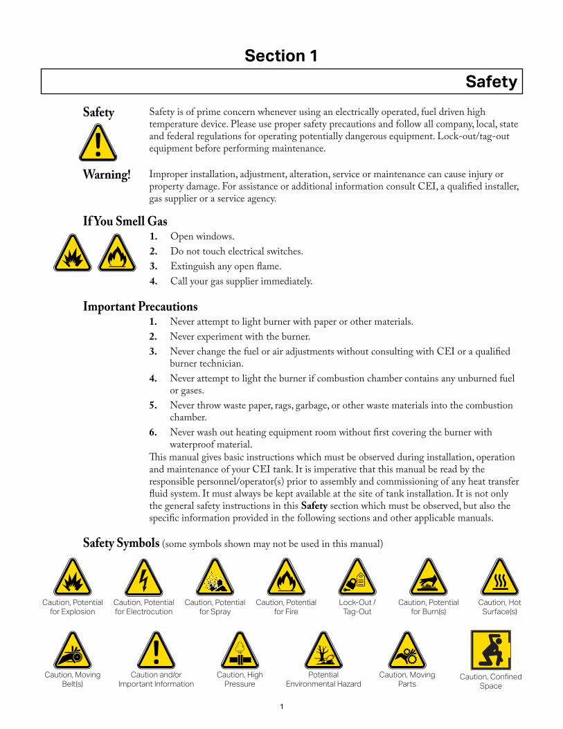
Safety Symbols (some symbols shown may not be used in this manual)
Safety is of prime concern whenever using an electrically operated, fuel driven high temperature device. Please use proper safety precautions and follow all company, local, state and federal regulations for operating potentially dangerous equipment. Lock-out/tag-out equipment before performing maintenance.
Improper installation, adjustment, alteration, service or maintenance can cause injury or property damage. For assistance or additional information consult CEI, a qualified installer, gas supplier or a service agency.
This manual gives basic instructions which must be observed during installation, operation and maintenance of your CEI tank. It is imperative that this manual be read by the responsible personnel/operator(s) prior to assembly and commissioning of any heat transfer fluid system. It must always be kept available at the site of tank installation. It is not only the general safety instructions in this Safety section which must be observed, but also the specific information provided in the following sections and other applicable manuals.
1. Never attempt to light burner with paper or other materials.2. Never experiment with the burner.3. Never change the fuel or air adjustments without consulting with CEI or a qualified
burner technician.4. Never attempt to light the burner if combustion chamber contains any unburned fuel
or gases.5. Never throw waste paper, rags, garbage, or other waste materials into the combustion
chamber.6. Never wash out heating equipment room without first covering the burner with
waterproof material.
1. Open windows.2. Do not touch electrical switches.3. Extinguish any open flame.4. Call your gas supplier immediately.
Section 1
Safety
Caution, Potential for Explosion
Caution, Potential for Electrocution
Caution, Confined Space
Caution, Moving Parts
Caution, Moving Belt(s)
Caution, High Pressure
Caution and/or Important Information
Potential Environmental Hazard
Caution, Potential for Spray
Caution, Potential for Fire
Caution, Potential for Burn(s)
Caution, Hot Surface(s)
Lock-Out / Tag-Out
1
Section 1
Safety
This Product May Contain A Chemical Known To The State Of California To Cause Cancer, Or Birth Defects Or Other Reproductive Harm.
WARNING!
This Product Can Expose You To Chemicals Including Diesel Engine Exhaust, Which Is Known To The State Of California To Cause Cancer.
WARNING!
2
Basic Safety Instructions• Lockout power to the equipment before working on it.• All drive guards and hand rails must be in place.• Check that the plant components are in good working condition prior to plant
start up.• Never remove, disable, defeat or bypass any safety device on the plant.• Make no modifications to your plant without recommendation or approval of a
representative of CEI Engineering or Service department.• Account for all personnel on the job site before starting the plant.• Avoid wearing loose clothing, necklaces, neckties or anything that could become
entangled in rotating machinery.• Avoid or tie up long hair.• Never leave the controls unattended while the plant is in operation.• Never walk on the material stockpiles or in the cold feed bins, to avoid engulfment by
loose feed stock.• Relieve internal pressure before disconnecting any high-pressure line. Thoroughly
tighten all fittings before reapplying pressure.• Keep away from power driven parts, even if they are not moving, unless they are
locked out.• Use extreme caution if you must approach running equipment.
• A written confined space plan, including recognizing and marking all confined spaces on site;
• Procedures to test and monitor the air inside confined spaces before and during all employee entries;
• Procedures to prevent unauthorized entries and to have an attendant outside the space at all times;
• Effective controls of all existing atmospheric or safety hazards inside the confined space;
• Employee and supervisor training on safe work procedures, hazard controls, and rescue procedures; and
• Effective rescue procedures which are immediately available on site.
Section 1
Safety
Employees should never enter a tank until all the safety precautions are in place and they have been authorized to enter. Emergency procedures must be in place and ready before any employee enters a confined space.In many jurisdictions, confined space regulations require all employers to have:
3
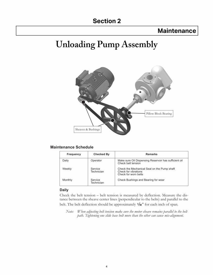
Maintenance Schedule
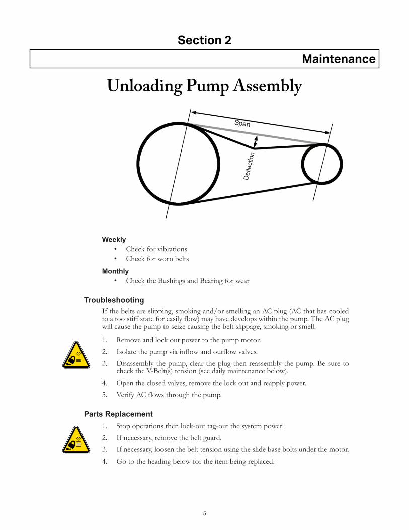
DailyCheck the belt tension – belt tension is measured by deflection. Measure the dis-tance between the sheave center lines (perpendicular to the belts) and parallel to thebelt. The belt deflection should be approximately " for each inch of span.
Note: When adjusting belt tension make sure the motor sheave remains parallel to the belt path. Tightening one slide base bolt more than the other can cause mis-alignment.
Frequency Checked By Remarks
Daily
Weekly
Monthly
Operator
Service Technician
Service Technician
Make sure Oil Dispensing Reservoir has sufficient oilCheck belt tension
Check the Mechanical Seal on the Pump shaftCheck for vibrationsCheck for worn belts
Check Bushings and Bearing for wear
Sheaves & Bushings
Pillow Block Bearing
Section 2
Maintenance
Unloading Pump Assembly
4
Weekly• Check for vibrations• Check for worn belts
Monthly• Check the Bushings and Bearing for wear
TroubleshootingIf the belts are slipping, smoking and/or smelling an AC plug (AC that has cooledto a too stiff state for easily flow) may have develops within the pump. The AC plugwill cause the pump to seize causing the belt slippage, smoking or smell.
1. Remove and lock out power to the pump motor.2. Isolate the pump via inflow and outflow valves.3. Disassembly the pump, clear the plug then reassembly the pump. Be sure to
check the V-Belt(s) tension (see daily maintenance below).4. Open the closed valves, remove the lock out and reapply power.5. Verify AC flows through the pump.
Parts Replacement1. Stop operations then lock-out tag-out the system power.2. If necessary, remove the belt guard.3. If necessary, loosen the belt tension using the slide base bolts under the motor.4. Go to the heading below for the item being replaced.
Span
Def
lect
ion
Section 2
Maintenance
Unloading Pump Assembly
5
Belts1. Remove the worn belts and inspect the groves on both sheaves. Clean or
replace the sheaves as necessary.2. Install the new belts.3. Adjust the belt tension – belt tension is measured by deflection. Measure the
distance between the sheave center lines (perpendicular to the belts) andparallel to the belt. The belt deflection should be approximately " for eachinch of span.
4. Re-install the belt guard and remove the lock-out tag-out. Restart operations.
Motor1. Remove the electrical access cover on the motor and label the incoming wires.
Disconnect the wires and conduit and remove them from the motor.2. Remove the belts. Take the sheave off the motor shaft.3. Remove the nuts and washers holding the motor in place then remove the
motor.4. Install the new motor using the nuts and washer removed above. Remove the
electrical access cover on the motor, connect the conduit and connect thewires labeled above. Re-install the electrical access cover.
5. Re-install the sheave and belts.6. Do steps 3 and 4 under Belts (above).
Pump1. Place a drip pan or absorbent material under the pump assembly and close any
isolation valves.
2. Let the system cool before proceeding. Hot oil can cause severe burns.3. Support the surrounding components then disconnect all plumbing attached
to the pump.4. Remove the sheave.5. Remove the nuts and washers holding the pump in place then remove the
pump. Discard the gaskets between the pump and other connections.6. Install the new pump and new gaskets using the nuts and washer removed
above.7. Do steps 3 and 4 under Belts (above).
Section 3
Maintenance
Unloading Pump Assembly
6
Contact Information
Office & Manufacturing Facility
CEI Service Department (General Contact)
Departmental Contacts
CEI ENTERPRISES, INC.An Astec CompanyP.O. Box 9156Albuquerque, New Mexico, U.S.A. 87119
Phone: (800) 545-4034 or (505) 842-5556 Fax: (505) 243-1422www.ceienterprises.com
Shanon Heath Service Manager Cell: (505) 908-8794
Sam D. Morgan Engineering Director Cell: (505) 400-8958
Johnny Romero Parts Representative Cell: (505) 235-2789
7


CEI ENTERPRISES, INC.245 Woodward Road, SE
Albuquerque, New Mexico, U.S.A. 87102
800.545.4034www.ceienterprises.com
© 2019 CEI Enterprises, Inc Publication # 19-05-056
Asphalt Unloading Pump