Embed Size (px)
Citation preview
Operation & Maintenance Manual for WP4/WP6NG Series Gas Generators
Green Power International Weichai
Operation & Maintenance Manual for
WP4/WP6NG Series Gas Generators
WEICHAI WESTPORT INC●
Operation & Maintenance Manual for WP4/WP6NG Series Gas Generators
Green Power International Weichai
Special Instructions
● Before operating a natural gas engine, the operator must read this operation and
maintenance manual carefully and follow the operation and maintenance procedures
specified in this manual in a strict way.
● This natural gas engine has undergone factory inspection according to the test
specifications in a strict way. Do not adjust any ECU data or increase the power of natural
gas engine arbitrarily; otherwise, all warranty commitments of our company will become
invalid.
● As engine control module (ECU) is a precision component, the user shall not disassemble
it; otherwise, all warranty commitments of our company will become invalid.
● As rotor shaft of turbocharger is a precision high-speed rotating component, disassembling
or collision is strictly prohibited; otherwise, all warranty commitments of our company
will become invalid.
● As there are strict requirements for torque and angle of rotation of main bearing bolt and
connecting rod bolt of a natural gas engine, the user shall not unscrew or disassemble the
bolts. As connecting rod bolts are disposable, they shall not be reused; otherwise, all
warranty commitments of our company will become invalid.
● The grade of engine oil added into a natural gas engine must meet the provisions of this
operation and maintenance manual. We suggest using the special oil for Weichai natural gas
engine and special oil filter for filtering. The operator must check whether the amounts of
coolant and engine oil in an engine meet the requirements before starting the engine every
time.
● For bad air source, banning engine working without gas filter, otherwise the service life of
engine will be shortened.
● When the calorific value of gas composition is lower than 49 MJ/kg, the power of engine
would relatively decrease.
● Operating a natural gas engine without an air filter is strictly prohibited.
● Do not put a new engine into operation before it is run in necessarily. A new engine shall be
put into trial operation for 50 hours before it is used normally.
Operation & Maintenance Manual for WP4/WP6NG Series Gas Generators
Green Power International Weichai
● The new spark plug tightening torque must be as specified and the ceramic body must be
cleaned up when changing the spark plug every time.
● The power supply and earth connection of a natural gas engine electronic control system shall
be disconnected before welding any component of a generator set.
● If the working environment temperature may be lower than 0℃ after shutdown but there is
no antifreeze additive in coolant, the coolant in water tank and engine shall be drained off.
● In order to avoid corrosion, each ex-works engine is oil-sealed. Usually the service life of an
engine oil seal is one year. After one year, the operator shall check and take necessary
remedial measures.
● Before using a new set, the operator shall check the natural gas line, the natural gas feeder
and the electrical system, and pay special attention to the electrical connection for
“looseness” and the high-voltage line for “virtual connection”.
● The operator shall make sure that the battery voltage is normal and there is sufficient voltage
for the normal operation of ignition and electronic control system of natural gas engine
before starting the engine. If the engine has not been started up for 3 times successively, the
natural gas part and the circuit part shall be rechecked carefully.
● The cooling water used in the engine must be soft water. [If ordinary water (hard water) is
used as the coolant of the engine, it is likely to develop scale in pressure reducer and the
“frosting” phenomenon when the engine is just started up.]
Operation & Maintenance Manual for WP4/WP6NG Series Gas Generators
Green Power International Weichai
Foreword
WP6/WP4NG series natural gas engine for power generation is made by improving the
previous Weichai WP6/WP4 series diesel engine for power generation through removing of
engine fuel system and adding of gas supply system and relevant devices. This natural gas
engine is characterized by compact structure, reliable operation, excellent technical
performances in reliability, power, economical efficiency and exhaust emission, quick start-up,
easy operation and least maintenance, etc. It has already become a new power source of power
generation equipment and is frequently used as a main or standby power source in coal mine,
oil field, farm, gas station and other places. In addition, it can be fueled by natural gas, methane
and biomass gas, etc.
This manual briefly introduces the technical parameters, performance indicators, structural
features and usage & maintenance precautions of WP6/WP4NG series natural gas generator.
The user shall comply with various specifications stipulated in this manual when using this
natural gas engine.
This manual deals with the basic model WP6/WP4NG series stand-alone natural gas generator.
As the product structure is improving as the product develops continuously, this operating
manual may lag behind such improvement. The user (or retailer) can also access
http://www.weichai.com for information of latest products.
Any user’s comments and suggestions are always welcomed.
We shall cooperate sincerely, continue to stay together and strive for the development of our
clean energy industry of China!
Operation & Maintenance Manual for WP4/WP6NG Series Gas Generators
Green Power International Weichai
Contents
Chapter I Product Technical Overview ............................................................................................. 1
1.1 Main structural features of natural gas engine .................................................................... 1
1.2 Model implication of WP6/WP4NG Series Natural Gas G-Drive Engine .......................... 1
1.3 Main technical parameters of WP6/WP4NG Series Natural Gas G-Drive Engin ............... 2
1.4 Torque and method for tightening main bolts & nuts of engine .......................................... 3
Chapter II Natural Gas Engine Control System ................................................................................ 4
2.1. Schematic diagram of natural gas control system .............................................................. 4
2.2 Engine control system main parts technical requirements and installation requirements ... 6
Chapter 3 Use and Operation of Natural Gas Engines .................................................................... 15
3.1 Unpacking of natural gas engines ..................................................................................... 15
3.2 Lifting of natural gas engines ............................................................................................ 15
3.3 Installation of natural gas engines ..................................................................................... 15
3.4 Preparatory work before startup ........................................................................................ 16
Chapter 4 Regular Inspection and Technical Maintenance of Natural Gas Engines ....................... 17
4.1 Maintenance period and specifications of industrial power natural gas engines .............. 17
4.2 Operation and maintenance specifications for main accessories of natural gas engines ... 17
Chapter 5 Analysis and Removal of Common Faults ..................................................................... 22
5.1 Diagnostic method ............................................................................................................ 23
5.2 Common faults and trouble removal ................................................................................. 23
Operation & Maintenance Manual for WP4/WP6NG Series Gas Generators
Green Power International Weichai 1
Chapter I Product Technical Overview
1.1 Main structural features of natural gas engine
● A cover per cylinder, dependable operation, easy disassembly.
● Frame-type main bearing structure and high complete machine rigidity which benefits the reliability and
service life of complete machine.
● Electronic throttle is adopted to control engine revolving speed.
● Mixture supply system uses mixer to regulate air-fuel ratio and adopts proportional mix and
supercharged inter-cooling method to stabilize gas supply.
● Water-cooling middle case turbocharger applicable to gas engine features is selected and circulating
water shall be used to cool down turbocharger lubrication cooling oil so as to effectively prevent
pressure bearing lubricating oil from coking and to improve turbocharger’s reliability.
● Designed gas mixing system satisfies gas fuel features to effectively support stable lean burn and
enhance thermal efficiency.
● Two pairs of friction couples of inlet, outlet valves and valve seats shall be made of materials fit for gas
engine’s operating characteristics so as to ensure high temperature abrasive resistance property and
excellent self-lubrication performance.
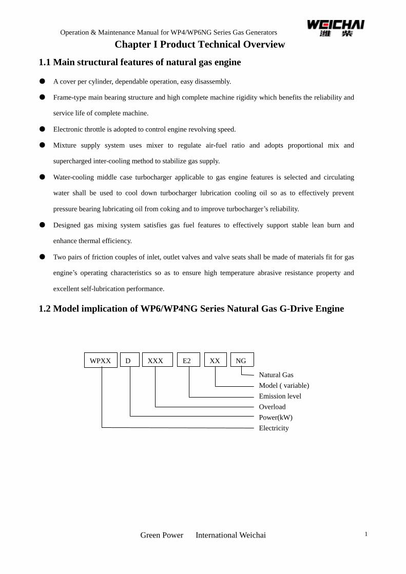
1.2 Model implication of WP6/WP4NG Series Natural Gas G-Drive Engine
WPXX
XXXX
XXXX
XXXX
XXX
XXX
XXX
E2 XX
X
NG D
Natural Gas
Model ( variable)
Emission level
Overload
Power(kW)
Electricity
generation
Product Series
Operation & Maintenance Manual for WP4/WP6NG Series Gas Generators
Green Power International Weichai 2
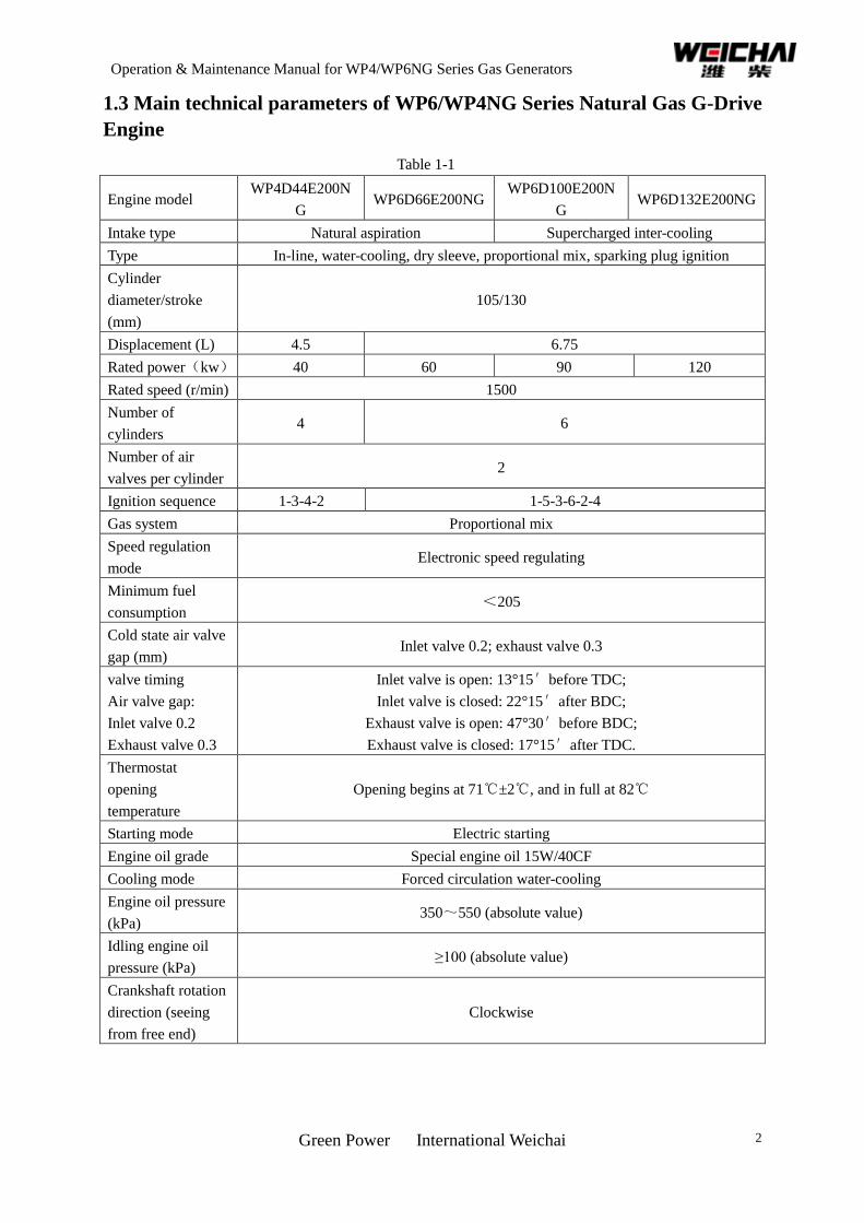
1.3 Main technical parameters of WP6/WP4NG Series Natural Gas G-Drive
Engine
Table 1-1
Engine model WP4D44E200N
G WP6D66E200NG
WP6D100E200N
G WP6D132E200NG
Intake type Natural aspiration Supercharged inter-cooling
Type In-line, water-cooling, dry sleeve, proportional mix, sparking plug ignition
Cylinder
diameter/stroke
(mm)
105/130
Displacement (L) 4.5 6.75
Rated power(kw) 40 60 90 120
Rated speed (r/min) 1500
Number of
cylinders 4 6
Number of air
valves per cylinder 2
Ignition sequence 1-3-4-2 1-5-3-6-2-4
Gas system Proportional mix
Speed regulation
mode Electronic speed regulating
Minimum fuel
consumption <205
Cold state air valve
gap (mm) Inlet valve 0.2; exhaust valve 0.3
valve timing
Air valve gap:
Inlet valve 0.2
Exhaust valve 0.3
Inlet valve is open: 13°15′before TDC;
Inlet valve is closed: 22°15′after BDC;
Exhaust valve is open: 47°30′before BDC;
Exhaust valve is closed: 17°15′after TDC.
Thermostat
opening
temperature
Opening begins at 71℃±2℃, and in full at 82℃
Starting mode Electric starting
Engine oil grade Special engine oil 15W/40CF
Cooling mode Forced circulation water-cooling
Engine oil pressure
(kPa) 350~550 (absolute value)
Idling engine oil
pressure (kPa) ≥100 (absolute value)
Crankshaft rotation
direction (seeing
from free end)
Clockwise
Operation & Maintenance Manual for WP4/WP6NG Series Gas Generators
Green Power International Weichai 3
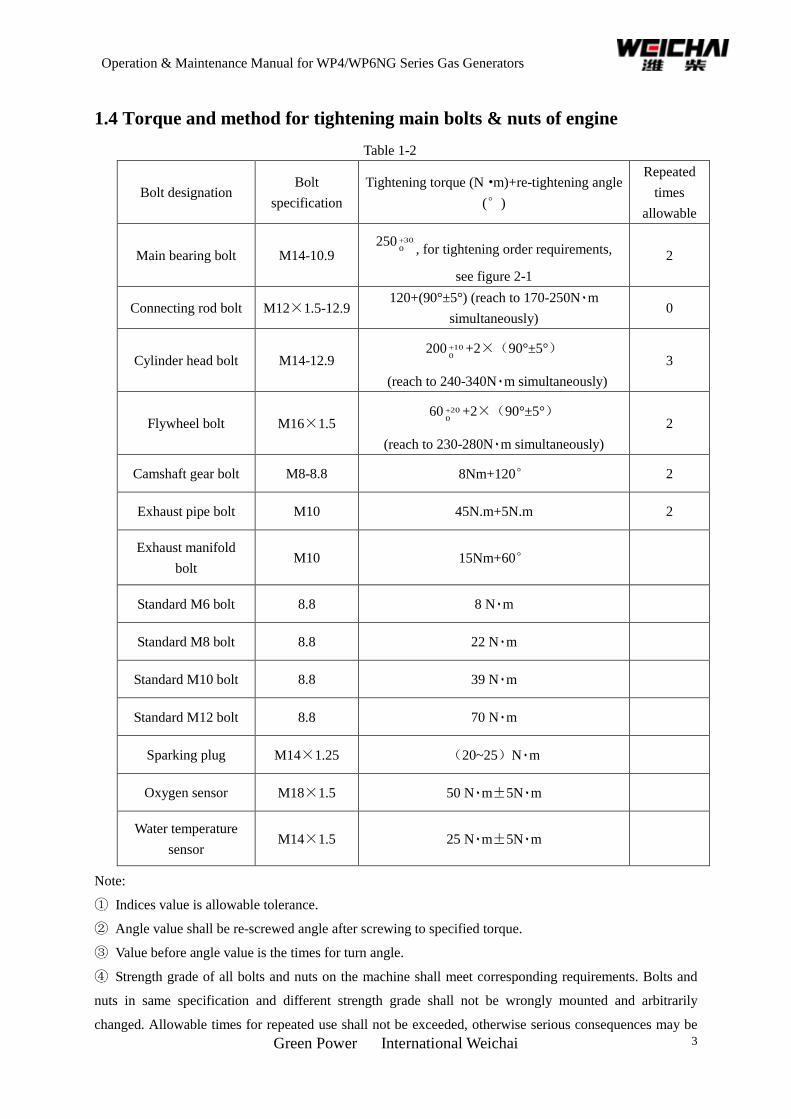
1.4 Torque and method for tightening main bolts & nuts of engine
Table 1-2
Bolt designation Bolt
specification
Tightening torque (N·m)+re-tightening angle
(°)
Repeated
times
allowable
Main bearing bolt M14-10.9 250 30
0
, for tightening order requirements,
see figure 2-1
2
Connecting rod bolt M12×1.5-12.9 120+(90°±5°) (reach to 170-250N٠m
simultaneously) 0
Cylinder head bolt M14-12.9 200 10
0
+2×(90°±5°)
(reach to 240-340N٠m simultaneously)
3
Flywheel bolt M16×1.5 60 20
0
+2×(90°±5°)
(reach to 230-280N٠m simultaneously)
2
Camshaft gear bolt M8-8.8 8Nm+120° 2
Exhaust pipe bolt M10 45N.m+5N.m 2
Exhaust manifold
bolt M10 15Nm+60°
Standard M6 bolt 8.8 8 N٠m
Standard M8 bolt 8.8 22 N٠m
Standard M10 bolt 8.8 39 N٠m
Standard M12 bolt 8.8 70 N٠m
Sparking plug M14×1.25 (20~25)N٠m
Oxygen sensor M18×1.5 50 N٠m±5N٠m
Water temperature
sensor M14×1.5 25 N٠m±5N٠m
Note:
① Indices value is allowable tolerance.
② Angle value shall be re-screwed angle after screwing to specified torque.
③ Value before angle value is the times for turn angle.
④ Strength grade of all bolts and nuts on the machine shall meet corresponding requirements. Bolts and
nuts in same specification and different strength grade shall not be wrongly mounted and arbitrarily
changed. Allowable times for repeated use shall not be exceeded, otherwise serious consequences may be

Operation & Maintenance Manual for WP4/WP6NG Series Gas Generators
Green Power International Weichai 4
caused.
Operation & Maintenance Manual for WP4/WP6NG Series Gas Generators
Green Power International Weichai 5
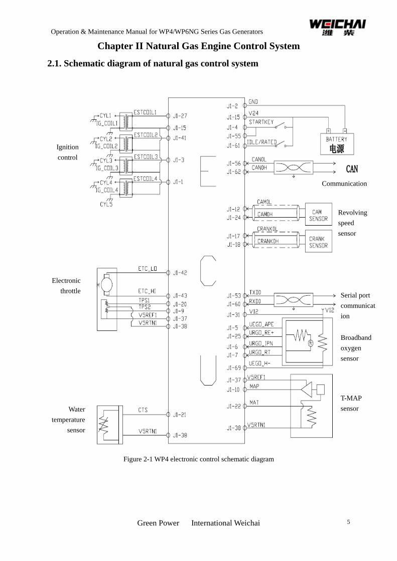
Chapter II Natural Gas Engine Control System
2.1. Schematic diagram of natural gas control system
Figure 2-1 WP4 electronic control schematic diagram
Ignition
control
Communication
Revolving
speed
sensor
Serial port
communicat
ion
Broadband
oxygen
sensor
T-MAP
sensor
Electronic
throttle
Water
temperature
sensor
Operation & Maintenance Manual for WP4/WP6NG Series Gas Generators
Green Power International Weichai 6
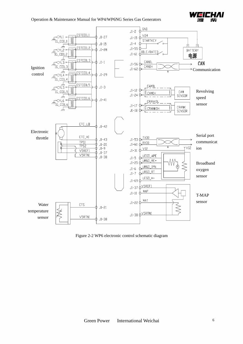
Figure 2-2 WP6 electronic control schematic diagram
Ignition
control
Electronic
throttle
Water
temperature
sensor
Communication
Revolving
speed
sensor
Serial port
communicat
ion
Broadband
oxygen
sensor
T-MAP
sensor
Operation & Maintenance Manual for WP4/WP6NG Series Gas Generators
Green Power International Weichai 7
2.2 Engine control system main parts technical requirements and installation
requirements
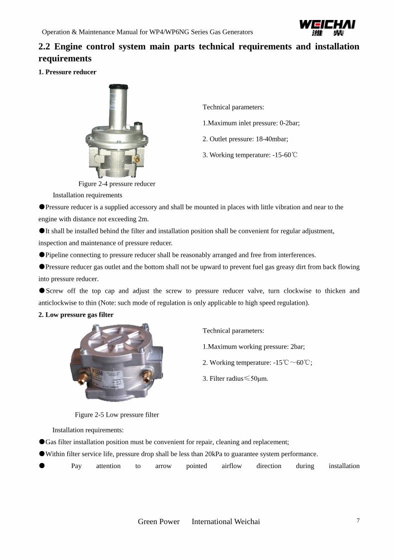
1. Pressure reducer
Figure 2-4 pressure reducer
Technical parameters:
1.Maximum inlet pressure: 0-2bar;
2. Outlet pressure: 18-40mbar;
3. Working temperature: -15-60℃
Installation requirements
●Pressure reducer is a supplied accessory and shall be mounted in places with little vibration and near to the
engine with distance not exceeding 2m.
●It shall be installed behind the filter and installation position shall be convenient for regular adjustment,
inspection and maintenance of pressure reducer.
●Pipeline connecting to pressure reducer shall be reasonably arranged and free from interferences.
●Pressure reducer gas outlet and the bottom shall not be upward to prevent fuel gas greasy dirt from back flowing
into pressure reducer.
●Screw off the top cap and adjust the screw to pressure reducer valve, turn clockwise to thicken and
anticlockwise to thin (Note: such mode of regulation is only applicable to high speed regulation).
2. Low pressure gas filter
Figure 2-5 Low pressure filter
Technical parameters:
1.Maximum working pressure: 2bar;
2. Working temperature: -15℃~60℃;
3. Filter radius≤50μm.
Installation requirements:
●Gas filter installation position must be convenient for repair, cleaning and replacement;
●Within filter service life, pressure drop shall be less than 20kPa to guarantee system performance.
● Pay attention to arrow pointed airflow direction during installation
Operation & Maintenance Manual for WP4/WP6NG Series Gas Generators
Green Power International Weichai 8
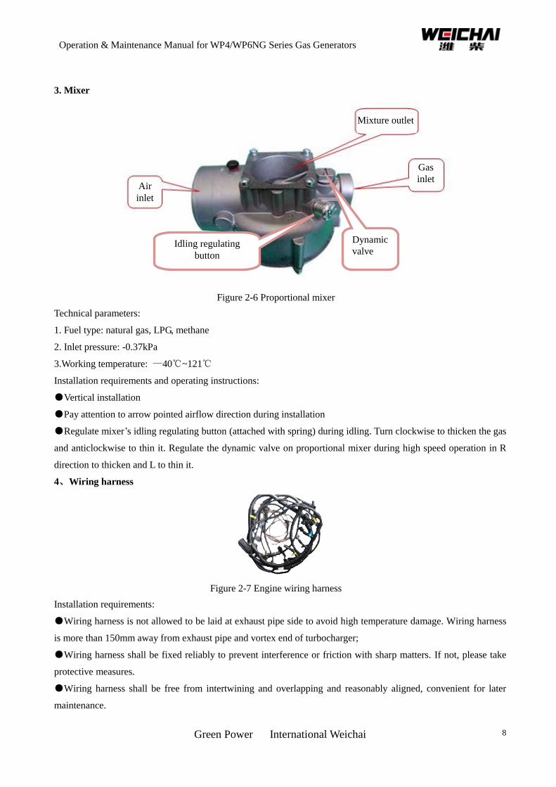
3. Mixer
Figure 2-6 Proportional mixer
Technical parameters:
1. Fuel type: natural gas, LPG, methane
2. Inlet pressure: -0.37kPa
3.Working temperature: —40℃~121℃
Installation requirements and operating instructions:
●Vertical installation
●Pay attention to arrow pointed airflow direction during installation
●Regulate mixer’s idling regulating button (attached with spring) during idling. Turn clockwise to thicken the gas
and anticlockwise to thin it. Regulate the dynamic valve on proportional mixer during high speed operation in R
direction to thicken and L to thin it.
4、Wiring harness
Figure 2-7 Engine wiring harness
Installation requirements:
●Wiring harness is not allowed to be laid at exhaust pipe side to avoid high temperature damage. Wiring harness
is more than 150mm away from exhaust pipe and vortex end of turbocharger;
●Wiring harness shall be fixed reliably to prevent interference or friction with sharp matters. If not, please take
protective measures.
●Wiring harness shall be free from intertwining and overlapping and reasonably aligned, convenient for later
maintenance.
Idling regulating
button
Dynamic
valve
Air
inlet
Gas
inlet
Mixture outlet
Operation & Maintenance Manual for WP4/WP6NG Series Gas Generators
Green Power International Weichai 9
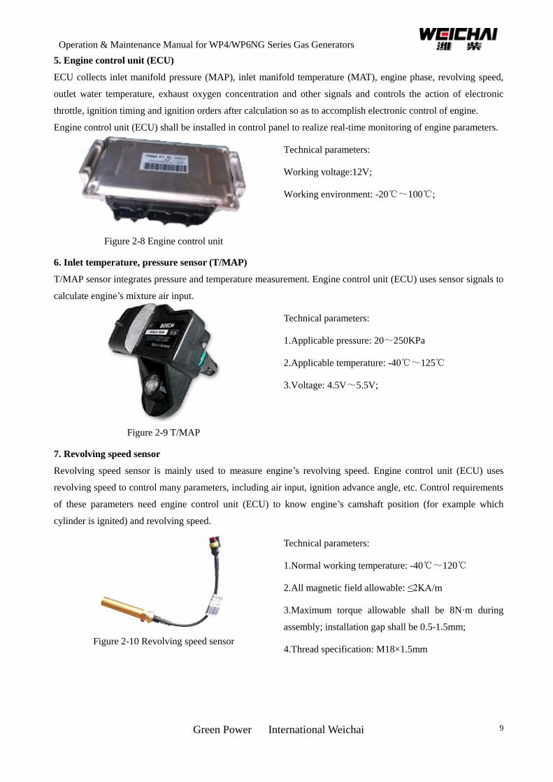
5. Engine control unit (ECU)
ECU collects inlet manifold pressure (MAP), inlet manifold temperature (MAT), engine phase, revolving speed,
outlet water temperature, exhaust oxygen concentration and other signals and controls the action of electronic
throttle, ignition timing and ignition orders after calculation so as to accomplish electronic control of engine.
Engine control unit (ECU) shall be installed in control panel to realize real-time monitoring of engine parameters.
Figure 2-8 Engine control unit
Technical parameters:
Working voltage:12V;
Working environment: -20℃~100℃;
6. Inlet temperature, pressure sensor (T/MAP)
T/MAP sensor integrates pressure and temperature measurement. Engine control unit (ECU) uses sensor signals to
calculate engine’s mixture air input.
Figure 2-9 T/MAP
Technical parameters:
1.Applicable pressure: 20~250KPa
2.Applicable temperature: -40℃~125℃
3.Voltage: 4.5V~5.5V;
7. Revolving speed sensor
Revolving speed sensor is mainly used to measure engine’s revolving speed. Engine control unit (ECU) uses
revolving speed to control many parameters, including air input, ignition advance angle, etc. Control requirements
of these parameters need engine control unit (ECU) to know engine’s camshaft position (for example which
cylinder is ignited) and revolving speed.
Figure 2-10 Revolving speed sensor
Technical parameters:
1.Normal working temperature: -40℃~120℃
2.All magnetic field allowable: ≤2KA/m
3.Maximum torque allowable shall be 8N·m during
assembly; installation gap shall be 0.5-1.5mm;
4.Thread specification: M18×1.5mm
Operation & Maintenance Manual for WP4/WP6NG Series Gas Generators
Green Power International Weichai 10
8. Water temperature sensor
Water temperature sensor is mainly used to measure cooling water temperature. ECU may regulate idle speed and
ignition advance angle in different water temperatures according to ECU stored data.
Figure 2-11 Water temperature sensor
Technical parameters:
1.Rated working voltage: 5±0.15V
2.Temperature measuring range: -40℃~﹢140℃
3. Normal working temperature of connectors: -40℃~
+130℃
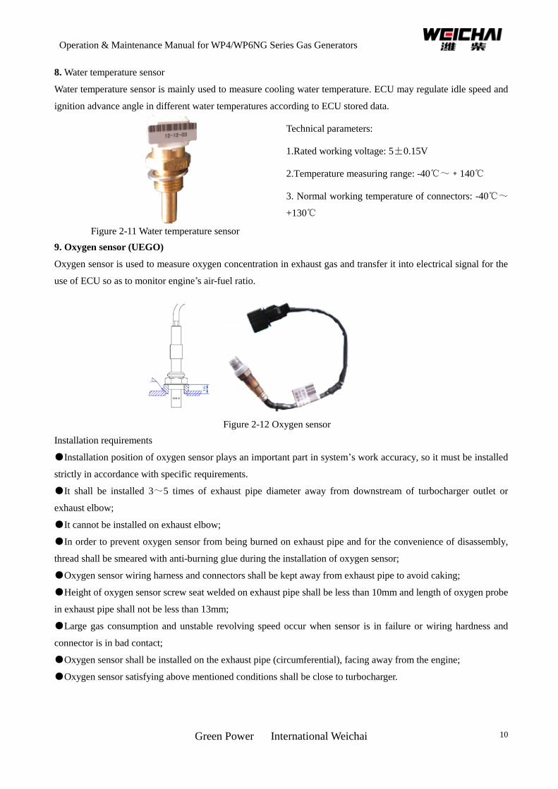
9. Oxygen sensor (UEGO)
Oxygen sensor is used to measure oxygen concentration in exhaust gas and transfer it into electrical signal for the
use of ECU so as to monitor engine’s air-fuel ratio.
Figure 2-12 Oxygen sensor
Installation requirements
●Installation position of oxygen sensor plays an important part in system’s work accuracy, so it must be installed
strictly in accordance with specific requirements.
●It shall be installed 3~5 times of exhaust pipe diameter away from downstream of turbocharger outlet or
exhaust elbow;
●It cannot be installed on exhaust elbow;
●In order to prevent oxygen sensor from being burned on exhaust pipe and for the convenience of disassembly,
thread shall be smeared with anti-burning glue during the installation of oxygen sensor;
●Oxygen sensor wiring harness and connectors shall be kept away from exhaust pipe to avoid caking;
●Height of oxygen sensor screw seat welded on exhaust pipe shall be less than 10mm and length of oxygen probe
in exhaust pipe shall not be less than 13mm;
●Large gas consumption and unstable revolving speed occur when sensor is in failure or wiring hardness and
connector is in bad contact;
●Oxygen sensor shall be installed on the exhaust pipe (circumferential), facing away from the engine;
●Oxygen sensor satisfying above mentioned conditions shall be close to turbocharger.
Operation & Maintenance Manual for WP4/WP6NG Series Gas Generators
Green Power International Weichai 11
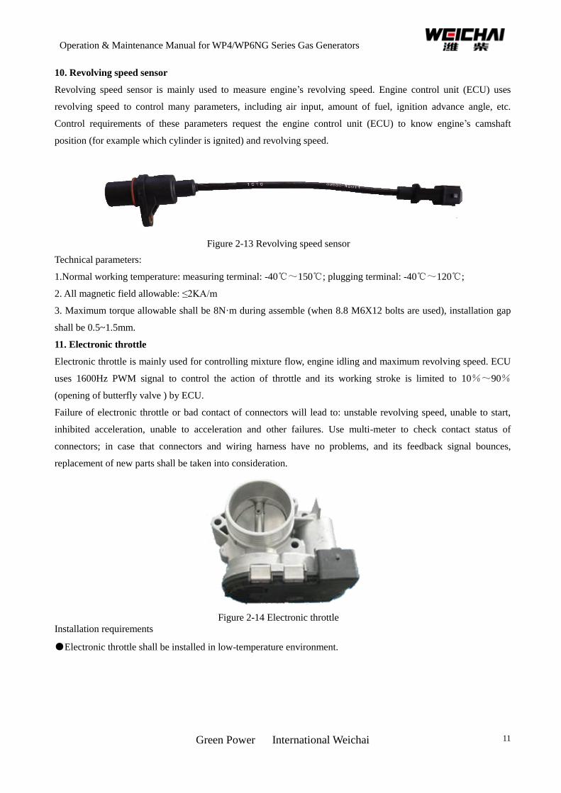
10. Revolving speed sensor
Revolving speed sensor is mainly used to measure engine’s revolving speed. Engine control unit (ECU) uses
revolving speed to control many parameters, including air input, amount of fuel, ignition advance angle, etc.
Control requirements of these parameters request the engine control unit (ECU) to know engine’s camshaft
position (for example which cylinder is ignited) and revolving speed.
Figure 2-13 Revolving speed sensor
Technical parameters:
1.Normal working temperature: measuring terminal: -40℃~150℃; plugging terminal: -40℃~120℃;
2. All magnetic field allowable: ≤2KA/m
3. Maximum torque allowable shall be 8N·m during assemble (when 8.8 M6X12 bolts are used), installation gap
shall be 0.5~1.5mm.
11. Electronic throttle
Electronic throttle is mainly used for controlling mixture flow, engine idling and maximum revolving speed. ECU
uses 1600Hz PWM signal to control the action of throttle and its working stroke is limited to 10%~90%
(opening of butterfly valve ) by ECU.
Failure of electronic throttle or bad contact of connectors will lead to: unstable revolving speed, unable to start,
inhibited acceleration, unable to acceleration and other failures. Use multi-meter to check contact status of
connectors; in case that connectors and wiring harness have no problems, and its feedback signal bounces,
replacement of new parts shall be taken into consideration.
Figure 2-14 Electronic throttle
Installation requirements
●Electronic throttle shall be installed in low-temperature environment.
Operation & Maintenance Manual for WP4/WP6NG Series Gas Generators
Green Power International Weichai 12
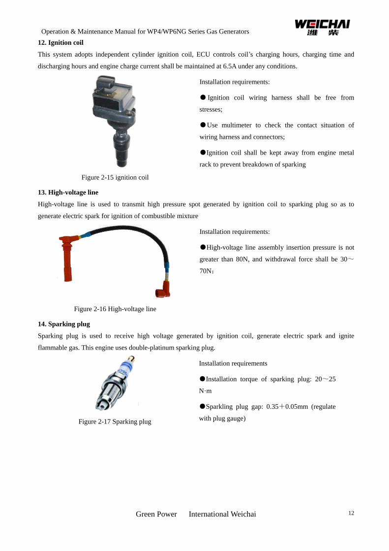
12. Ignition coil
This system adopts independent cylinder ignition coil, ECU controls coil’s charging hours, charging time and
discharging hours and engine charge current shall be maintained at 6.5A under any conditions.
Figure 2-15 ignition coil
Installation requirements:
● Ignition coil wiring harness shall be free from
stresses;
●Use multimeter to check the contact situation of
wiring harness and connectors;
●Ignition coil shall be kept away from engine metal
rack to prevent breakdown of sparking
13. High-voltage line
High-voltage line is used to transmit high pressure spot generated by ignition coil to sparking plug so as to
generate electric spark for ignition of combustible mixture
Figure 2-16 High-voltage line
Installation requirements:
●High-voltage line assembly insertion pressure is not
greater than 80N, and withdrawal force shall be 30~
70N;
14. Sparking plug
Sparking plug is used to receive high voltage generated by ignition coil, generate electric spark and ignite
flammable gas. This engine uses double-platinum sparking plug.
Figure 2-17 Sparking plug
Installation requirements
●Installation torque of sparking plug: 20~25
N·m
●Sparkling plug gap: 0.35+0.05mm (regulate
with plug gauge)
Operation & Maintenance Manual for WP4/WP6NG Series Gas Generators
Green Power International Weichai 13
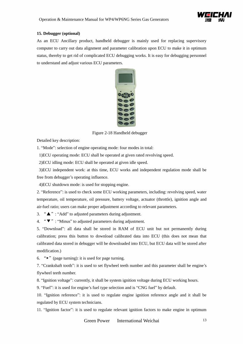
15. Debugger (optional)
As an ECU Ancillary product, handheld debugger is mainly used for replacing supervisory
computer to carry out data alignment and parameter calibration upon ECU to make it in optimum
status, thereby to get rid of complicated ECU debugging works. It is easy for debugging personnel
to understand and adjust various ECU parameters.
Figure 2-18 Handheld debugger
Detailed key description:
1. “Mode”: selection of engine operating mode: four modes in total:
1)ECU operating mode: ECU shall be operated at given rated revolving speed.
2)ECU idling mode: ECU shall be operated at given idle speed.
3)ECU independent work: at this time, ECU works and independent regulation mode shall be
free from debugger’s operating influence.
4)ECU shutdown mode: is used for stopping engine.
2. “Reference”: is used to check some ECU working parameters, including: revolving speed, water
temperature, oil temperature, oil pressure, battery voltage, actuator (throttle), ignition angle and
air-fuel ratio; users can make proper adjustment according to relevant parameters.
3. “▲”: “Add” to adjusted parameters during adjustment.
4. “▼”: “Minus” to adjusted parameters during adjustment.
5. “Download”: all data shall be stored in RAM of ECU unit but not permanently during
calibration; press this button to download calibrated data into ECU (this does not mean that
calibrated data stored in debugger will be downloaded into ECU, but ECU data will be stored after
modification.)
6. “▶”(page turning): it is used for page turning.
7. “Crankshaft tooth”: it is used to set flywheel teeth number and this parameter shall be engine’s
flywheel teeth number.
8. “Ignition voltage”: currently, it shall be system ignition voltage during ECU working hours.
9. “Fuel”: it is used for engine’s fuel type selection and is “CNG fuel” by default.
10. “Ignition reference”: it is used to regulate engine ignition reference angle and it shall be
regulated by ECU system technicians.
11. “Ignition factor”: it is used to regulate relevant ignition factors to make engine in optimum
Operation & Maintenance Manual for WP4/WP6NG Series Gas Generators
Green Power International Weichai 14
status and it shall be regulated by ECU system technicians.
12. “Throttle”: it is used to set the minimum opening and working opening of throttle. Among
which, working opening is related to engine idling. In case that engine idling is higher than stated
idle speed, idle speed can be reduced through regulating working throttles; generally make few
changes to minimum opening of throttle.
13. “Over-speed revolving speed”: it is used to set engine’s maximum revolving speed, engine
enters into idling operation when engine’s revolving speed is higher than set value.
14. “Target revolving speed” : it is used to set engine’s target revolving speed, generally, set value
is 1-2 round higher than set value.
15. “Idle speed”: it is used to set engine’s idle speed.
16. “Proportion”: regulate “proportion” parameter among PID control parameters and default
parameter shall be 0.42.
17. “Integral” : regulate “integral” parameter among PID control parameters and parameter shall
be 0.53 by default.
18. “Differential”: regulate “differential” parameter among PID control parameters and default
parameter shall be 0.32.
19. “Revolving speed feed-forward”: regulate revolving speed fee-forward by ECU system
technician.
20、 “Sensitivity”: regulate engine stability in the process of operation and default value shall be
1.00.
21. “Acceleration time”: regulate acceleration time of engine switching over from idling mode to
working mode. The bigger the data is, the shorter the acceleration time will be. Otherwise, it shall
be on the contrary.
22. “Data backup”: calibration data of other debugged unit shall be saved as the refreshing
benchmark of same unit data.
23. “Backups download”: calibrated data shall be downloaded into the unit and saved data shall be
downloaded to ECU.
24. “Factory data”: ECU shall be restored to ex-factory settings.
Operation & Maintenance Manual for WP4/WP6NG Series Gas Generators
Green Power International Weichai 15
Chapter 3 Use and Operation of Natural Gas Engines
3.1 Unpacking of natural gas engines
After unpacking the natural gas engine, the user shall count the engine and its accessories first in
accordance with the packing list. After that, the user shall check the engine appearance for damage and the
connecting pieces for looseness, and complete the following works:
◆ Wipe the antirust coat and corrosion inhibitor on the exposed parts;
◆ If the oil pan is not filled with oil, according to the agreement between the manufacturer and the
user, fill oil into it. If the oil pan is filled with engine oil containing running-in accelerating
agent before leaving our factory, we suggest that the user drain off the old oil and replace with
new oil after 50 hours of trial operation.
◆ If the engine is filled with coolant before leaving our factory based on the user needs, according
to the agreement between the manufacturer and the user, the user shall check the performance of
coolant after unpacking the engine. The coolant is usable if it can lower the freezing point down
to -30℃ or -35℃, with a PH value between 7 and 8 (neutral) and the total hardness value is
between 5 and 15°d [9 and 15°f (hardness)]; otherwise, the user shall drain off the coolant, and
refill coolant containing anti-freeze additive into the engine.
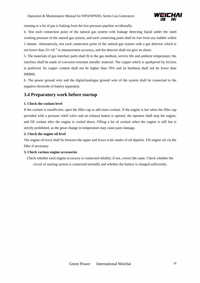
3.2 Lifting of natural gas engines
Being lifted, the center line of engine crankshaft shall keep horizontal. Lifting when engine is not upright or
without lifting frame is strictly prohibited. The lifting up and down shall be carried out slowly (see Figure
3-1).
Figure 3-1 Lifting diagram of natural gas engines
3.3 Installation of natural gas engines
1. During installation, the center line of engine crankshaft and the input shaft axis of transmission gear
(gear case, gearbox or generator, etc) shall be coaxial, and the crankshaft shall not be subject to the
additional axial force caused by installation.
2. The natural gas system design shall minimize the number of connection points on the high-pressure
pipeline and guarantee the convenient construction, good sealing, easy-to-check and high reliability of
connection points on the pipeline.
3. The high-pressure pipeline of natural gas system shall be provided with an upstream over-current
protection device to cut off the natural gas line reliably when the ignition switch is off, the engine is not
Wrong Correct
Operation & Maintenance Manual for WP4/WP6NG Series Gas Generators
Green Power International Weichai 16
running or a lot of gas is leaking from the low-pressure pipeline accidentally.
4. Test each connection point of the natural gas system with leakage detecting liquid under the rated
working pressure of the natural gas system, and each connecting point shall be free from any bubble within
1 minute. Alternatively, test each connection point of the natural gas system with a gas detector which is
not lower than 25× 610 in measurement accuracy, and the detector shall not give an alarm.
5. The materials of gas interface parts shall fit to the gas medium, service life and ambient temperature; the
interface shall be made of corrosion-resistant metallic material. The copper which is sparkproof by friction
is preferred. Its copper content shall not be higher than 70% and its hardness shall not be lower than
HRB60.
6. The power ground wire and the digital/analogue ground wire of the system shall be connected to the
negative electrode of battery separately.
3.4 Preparatory work before startup
1. Check the coolant level
If the coolant is insufficient, open the filler cap to add more coolant. If the engine is hot when the filler cap
provided with a pressure relief valve and an exhaust button is opened, the operator shall stop the engine,
and fill coolant after the engine is cooled down. Filling a lot of coolant when the engine is still hot is
strictly prohibited, as the great change in temperature may cause parts damage.
2. Check the engine oil level
The engine oil level shall be between the upper and lower scale marks of oil dipstick. Fill engine oil via the
filler if necessary.
3. Check various engine accessories
Check whether each engine accessory is connected reliably; if not, correct the same. Check whether the
circuit of starting system is connected normally and whether the battery is charged sufficiently.
Operation & Maintenance Manual for WP4/WP6NG Series Gas Generators
Green Power International Weichai 17
Chapter 4 Regular Inspection and Technical Maintenance of Natural
Gas Engines
4.1 Maintenance period and specifications of industrial power natural gas
engines
1. Maintenance period of industrial power natural gas engines
First maintenance (P): after a new engine has run for 30 hours to 50 hours
The first level maintenance (WD1): once every 250 operation hours
The second level maintenance (WD2): once every 500 operation hours
The third level maintenance (WD3): once every 1000 operation hours
The fourth level maintenance (WD4): once every 3000 operation hours
2. Maintenance items of natural gas engines
Maintenance
Programs Maintenance Items Maintenance Interval
Daily
Inspection
Check whether the engine oil level is normal; check whether the
coolant level is normal; check whether the driving belt is worn; check
whether the cooling fan is loose or damaged; check whether the
natural gas supply system is leaking; check whether the heating water
circulates normally in the natural gas supply system; check whether
the circuit of electrical control system is connected reliably; check
whether the air filter becomes loose or is leaking air.
Carry out inspections
and maintenance
according to specified
routine inspection and
maintenance periods.
When performing the
second, third and
fourth levels
maintenance, the first
level maintenance
items shall be
performed as well.
The user should use
the engine oil, engine
oil filter element and
accessories special for
Weichai natural gas
engines oil.
First
Mandatory
Maintenance
Replace the engine oil and engine oil filter element; check and adjust
the tension of belt; check the tightness of each pipeline clamp; check
the tightness of each bolt; tighten up the cylinder cap bolt.
Routine
Inspection
Clean up the natural gas filter; check the tightness of each pipeline
(including water line, air line, gas line and oil line) clamp; check
whether the natural gas system is leaking; check the natural gas
supply pressure in natural gas system.
First Level
Maintenance
Check and adjust the valve clearance; check the air filter; check and
adjust the tightness of belt; check the tightness of each pipeline
(including water line, air line, gas line and oil line) clamp; check the
spark plug; check the high-voltage line; check the ignition advance
angle; check and replace the gas filter element; check the coolant
volume.
Operation & Maintenance Manual for WP4/WP6NG Series Gas Generators
Green Power International Weichai 18
Second Level
Maintenance
Replace the voltage stabilizer repair kit; clean up the mixer and
electronic throttle valve; clean up the injection valve.
Third Level
Maintenance
Check the high-voltage line of spark plug; and it is recommended to
replace it.
Fourth Level
Maintenance
Check the turbocharger and clean up the cooling system; replace the
coolant; replace the pressure reducer repair kit.
3. Specifications for spare parts and oil products
The engine user must purchase special accessories and special engine oil from the special Weichai
maintenance service center, in order to guarantee the good service of the equipment and to extend the
service life.
4. Maintenance specification
After purchasing a Weichai industrial power product and mounting it well, the user shall inform the special
Weichai maintenance service center and ask a technician for debugging the equipment. In case of any fault
during the warranty period, the user shall inform the special Weichai maintenance service center and ask for
services.
4.2 Operation and maintenance specifications for main accessories of
natural gas engines
1. Maintenance of gas line
1. The gas filter shall be maintained regularly. Check whether the gas line is blocked and replace the gas
filter element once every 300 to 500 operation hours of engine.
2. The natural gas to be used shall be standard LNG or CNG. If the poor quality natural gases containing a
high impurity or water content, e.g. methane or coal bed methane is used, they must receive coarse
filtration and dehydration treatment before entering into engine; otherwise, the engine performance will be
influenced and the service life of engine will be shortened.
2. Maintenance of inter-cooling radiator
1. Cleaning of radiator
The water radiator shall be maintained frequently to guarantee the sufficient heat exchange performance
between coolant and air. In normal conditions, the surface and inside of water radiator shall be cleaned up
every 500 operation hours of engine. In order to clean up the internal scale and precipitated impurities, the
water in radiator shall be drained off first. After that, inject pressure clean water (such as tap water) into the
radiator core until the water flowing out is clean.
2. Daily cautions
When the engine is in service, the pressure cap shall be closed to avoid influencing the normal operation of
cooling system. The operator shall check the coolant level in water radiator frequently and replenish
coolant timely to avoid bad impact on the cooling effect of system and deterioration of engine cavitation
erosion due to low coolant level. When the coolant level is too low, the coolant shall be filled into water
radiator carefully to prevent steam from hurting people.
Operation & Maintenance Manual for WP4/WP6NG Series Gas Generators
Green Power International Weichai 19
[Note]: Do not open the pressure cap on water tank when the engine is running under a heavy load. It is
preferred not to screw off the pressure cap until the water temperature is below 70℃ after the engine stops
running. This is very important. Before starting the engine, do not fill coolant into the empty cooling
system too fast. The intervals between two fillings should be two minutes to allow the air to flow off the
cooling system completely. The water drain valve on the engine working in a low-temperature environment
shall be opened immediately to drain off the cooling water in water radiator and to avoid frost crack after
the engine stops running.
3. Operation and maintenance of air filter
Warning! The service life of your engine may be shortened greatly due to wrong maintenance
methods.
1. The air filter shall match the performance index of engine in a strict way; otherwise, the dynamic
property and economy performance of engine will be influenced.
2. If the air filter is provided with a warning device, the warning device shall be observed first before the
natural gas engine is started. When the intake resistance indicator give an alarm (turns red), the air filter
element shall be maintained.
3. The filter adopting multistage filtration technology must be provided with a coarse strainer.
4. When mounting the dust exhausting pipe, the pipe shall not be bend sharply and shall be free from air
leakage.
5. Prevent water from entering into the air filter.
6. When maintaining an air filter with a safety filter element, do not disassemble the safety filter element.
7. In normal working conditions, the paper main filter element of fine filter shall be maintained once
every 100 to 200 operation hours of engine. Remove the main filter element and tap or shake off the dust
inside. Check each sealing element of it and replace any damaged one. The clean and dry compressed air
not exceeding 500kpa may be used from blowing from inside of filter element. Put a lit bulb inside the
filter element and observe externally whether any light can pass through the filter element, in order to
confirm whether there is crack, pierced hole or other damages. Cleaning the main filter element with oil or
water is strictly prohibited.
8. The main filter element shall be replaced after having working for 1000 to 2000 hours. In the meantime,
the safety filter element shall be replaced.
9. The filter element assembly shall be replaced in the following cases:
1) The filter element is broken.
2) The warning device is still giving alarm after a clean filter element has been mounted.
3) After the filter element has been cleaned up for 3 to 6 times.
When replacing a filter element, the operator must use the filter element of a reliable quality in order
to guarantee the reliability of engine. It is recommended to purchase the genuine parts.
4. Operation and maintenance of turbocharger
The engine oil of turbocharger is drained from the main oil line of engine, and returns to the bottom of
crankcase after lubricating and cooling the turbocharger are complete.
1. A good lubrication is crucial to the normal operation of turbocharger. Therefore, the engine oil filter
Operation & Maintenance Manual for WP4/WP6NG Series Gas Generators
Green Power International Weichai 20
element shall be cleaned up or replaced regularly.
2. The turbocharger works at an extremely high rotating speed (about 70000 to 100000r/min). Therefore,
the engine shall run idle (for about 5 minutes; the duration may be shortened as appropriate in case of a
short-term shutdown) before it is loaded. Do not shut down the engine immediately when it is running at a
high speed under a heavy load. The load and rotating speed shall be lowered gradually and the engine shall
idle for 3 to 5 minutes; otherwise the turbocharger bearing will be damaged and become unusable.
3. Disassemble and check the compressor casing and turbine casing regularly, and clean up the impeller
and the flow passage in casing. When reassembling the turbocharger, fill clean engine oil via the filler
opening.
5. Operation and maintenance of starter
1. Starter is a short-time service device. Its starting time shall not exceed 15S every time. The interval
between successive starting shall be longer than 30S.
2. The engine shall be preheated when the temperature is below 5℃ in winter.
3. Release the starting switch immediately once the engine is started up so as to disengage the drive gear
of starter from the flywheel ring gear.
4. Energizing the starter before the engine stops running is strictly prohibited, so as to avoid damage due
to collision between the flywheel and the starter gear.
5. The wiring of a starter must be based on the wiring diagram of the starter during installation. Make sure
that the battery is disconnected from the main starting line of starter.
6. The fastening pieces of starter and wire insulation must be checked frequently for damage; the wires
shall be well-contacted and the dirt shall be removed.
6. Operation and maintenance of generator
1. Reasonable allocation: The basic electricity consumption of common electric appliances in the
complete machine shall be satisfied when the generator is idling. Any unreasonable match between the
generator and electric appliances in the complete machine may cause low battery energy or even regulator
damage or stator burnt-out due to overheating of generator. The minimum working speed of generator must
be guaranteed. If the idle speed of generator is set too low, the generator speed will be too low, which will
cause the above mentioned faults as well.
2. Secure installation: The generator shall be mounted on engine correctly, securely and reliably. The
mounting bolts must match the mounting holes on generator and be tightened up. The pulley groove and
the driving wheel groove shall be in the same plane. The mounting bracket of generator must meet the
requirements for necessary strength and rigidity; otherwise the generator may be damaged due to the
insecure installation.
3. The belt tension shall not be overloose or overtight. Usually the belt tension is proper when the belt can
be pressed down by 10 to 20 mm under a force of 150N (15 kilogram force) by hand at the 1/2 center
distance between two pulleys. The belt tension shall be checked once every 2 months of operation. The
generator may “rotate less turns” when the belt is overloose, which may cause insufficient power
generation, low battery energy, stator burnt-out and bearing damage, etc.
4. Keep away from heat source and splashing mud; prevent external splashes from entering into the
Operation & Maintenance Manual for WP4/WP6NG Series Gas Generators
Green Power International Weichai 21
generator and causing damage; try to guarantee a good application environment for generator.
5. Usually the working ambient temperature of generator is between -40℃ and 93℃. The generator shall
be mounted in a place which is away from the heat source upon the approval of generator manufacturer or
supplier (the distance from heat source: ≥400mm; or an effective thermal baffle is mounted).
6. The wire shall be sized reasonably and connected correctly and securely. Each connection terminal of
generator should not be connected in a wrong way to avoid wires burnt-out or generator electrical parts
damage. Selecting a reasonable wire diameter should be based on the premise that the complete output of
generating capacity of generator be guaranteed, and it is also the foundation for electricity safety for the
complete machine.
7. The wiring of battery and generator must be disconnected before the generator is disassembled or the
complete machine is being welded. The disassembly and repair of generator must be carried out by
professionals. During installation, check whether each insulation pad and sleeve is in good condition; any
damaged or broken insulation pad and sleeve must be replaced! The positive electrode side of generator and
the generator shell shall not have a short circuit to avoid serious accidents involving the complete machine.
8. After the engine is started, it shall reach a high speed from a low speed. Observe whether the charging
indicator is on when the speed is low, and off when the speed is high. If not, please find out the reason
immediately;
9. Observe whether the polarity of battery is “negative grounded”; if not, the generator and regulator will
be burnt out;
10. When the generator is in service, do not check whether the generator is generating electric power by
means of “testing sparks while grounded”; otherwise, the test lamp or diode may be burnt out;
11. When connecting the rectifier to the stator winding, do not check the insulation condition of generator
using a mega-ohm meter or 220V AC power supply;
12. The generator must be reliably connected to the battery. The sudden disconnection will generate a high
voltage and damage the generator or voltage regulator.
13. When selecting a regulator matching the AC generator, the voltage class of AC generator must be
identical to that of regulator; the ground type of AC generator must be identical to that of regulator; the
power of regulator shall not be lower than that of generator;
14. The wire connection must be correct.
7. Operation and maintenance of oil pump
WP6 /WP4NG series engine oil pumps are of external gear type. Each gear pump uses two gears with
identical number of teeth to engage with each other and brings engine oil to the oil outlet from the low
pressure oil chamber via the reverse rotation of two gears and the clearance between them. The constant
rotation of gears keeps the engine oil volume in oil chamber increasing and the pressure increasing, so as to
guarantee the sufficient oil supply for each lubricating system of engine.
The performance of engine oil pump mainly depends on the clearance (end clearance and radial clearance)
between oil pump gear and casing. When the clearance is overlarge, the engine oil will leak seriously, and
the engine oil pressure will drop and the oil volume will decrease. When the clearance is undersize, the gear
will wear out seriously.

Operation & Maintenance Manual for WP4/WP6NG Series Gas Generators
Green Power International Weichai 22
If the oil supply pressure drops, the oil pump shall be maintained when the other engine faults are
eliminated. When maintaining an engine oil pump, the maintenance personnel shall observe the oil pump
for oil leak and burn first. If there is no oil leak or burn, the maintenance personnel shall check the pressure
relief valve and disassemble the oil pump. Check whether the spring of pressure relief valve is softened or
whether the gear, pump body or end cap is worn seriously. Replace the oil pump if necessary.
If the oil pressure is overhigh, the pressure relief valve shall be disassembled for inspection. on The most
important is to inspect whether the pressure relief valve can be opened or not.
Be careful not to damage the end cap, pump body junction surface and each locating pin when
disassembling and reassembling an oil pump.
Operation & Maintenance Manual for WP4/WP6NG Series Gas Generators
Green Power International Weichai 23
Chapter 5 Analysis and Removal of Common Faults
WP6/WP4NG Series natural gas engines are designed and manufactured in compliance with a strict quality
assurance system. Each engine leaving our factory is tested as specified. In addition, natural gas engine is a
kind of precision machinery. Its long-term performance guarantee is inseparable from the normal
maintenance. Usually the following causes may lead to the early failure of an engine:
◆ Unprofessional operation and poor management and operation;
◆ The engine has not been maintained or repaired as per schedule or even has been repaired instead
of being maintained;
◆ The accessory quality is poor; especially the counterfeit and shoddy products will shorten the
service life of an engine greatly;
◆ The grade of lubricating oil is improper or disqualified.
5.1 Diagnostic method
The common faults diagnostic methods of natural gas engine include:
◆ Observational method: Determine the fault by observing the fault characteristics such as smoke
exhaust from engine;
◆ Listening method: Determine the nature and degree of faulty parts by listening to the abnormal
sound from the engine;
◆ Cylinder disconnection method: Stop one cylinder and determine whether this cylinder is in fault.
Usually the maintenance personnel stop supplying natural gas to the targeted cylinder and
compare the changes in engine state before and after that in order to further find out the faulty
parts and cause, or to narrow down the range;
◆ Comparison method: the maintenance personnel replace some assemblies or parts to determine
whether they are in fault.
Note:
① The causes for engine faults shall be determined carefully. Do not disassemble the engine
arbitrarily before figuring out the causes; otherwise, the fault cannot be removed and a more serious
fault may be further caused due to improper reassembly after disassembly.
② Please send the key parts such as ECU, electronic throttle valve and turbocharger to the
maintenance stations appointed by Weichai for maintenance and inspection.
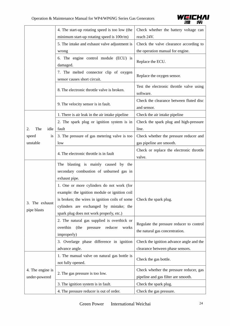
5.2 Common faults and trouble removal
Table 5-1 Engine faults and analysis
Common Faults Possible Causes Fault Inspection and Treatment
1. The engine
cannot be
started
1. The natural gas bottle is empty or the hand
valve on gas bottle is not opened.
2. The gas pressure is too low. Check the gas pipeline for gas leak.
3. There is no sufficient gas intake Check the air filter and gas intake system
for blockage and air leak.
Operation & Maintenance Manual for WP4/WP6NG Series Gas Generators
Green Power International Weichai 24
4. The start-up rotating speed is too low (the
minimum start-up rotating speed is 100r/m)
Check whether the battery voltage can
reach 24V.
5. The intake and exhaust valve adjustment is
wrong
Check the valve clearance according to
the operation manual for engine.
6. The engine control module (ECU) is
damaged. Replace the ECU.
7. The melted connector clip of oxygen
sensor causes short circuit. Replace the oxygen sensor.
8. The electronic throttle valve is broken. Test the electronic throttle valve using
software.
9. The velocity sensor is in fault. Check the clearance between fluted disc
and sensor.
2. The idle
speed is
unstable
1. There is air leak in the air intake pipeline Check the air intake pipeline
2. The spark plug or ignition system is in
fault
Check the spark plug and high-pressure
line.
3. The pressure of gas metering valve is too
low
Check whether the pressure reducer and
gas pipeline are smooth.
4. The electronic throttle is in fault Check or replace the electronic throttle
valve.
3. The exhaust
pipe blasts
The blasting is mainly caused by the
secondary combustion of unburned gas in
exhaust pipe.
1. One or more cylinders do not work (for
example: the ignition module or ignition coil
is broken; the wires in ignition coils of some
cylinders are exchanged by mistake; the
spark plug does not work properly, etc.)
Check the spark plug.
2. The natural gas supplied is overthick or
overthin (the pressure reducer works
improperly)
Regulate the pressure reducer to control
the natural gas concentration.
3. Overlarge phase difference in ignition
advance angle.
Check the ignition advance angle and the
clearance between phase sensors.
4. The engine is
under-powered
1. The manual valve on natural gas bottle is
not fully opened. Check the gas bottle.
2. The gas pressure is too low. Check whether the pressure reducer, gas
pipeline and gas filter are smooth.
3. The ignition system is in fault. Check the spark plug.
4. The pressure reducer is out of order. Check the gas pressure.
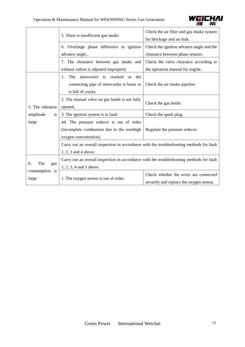
Operation & Maintenance Manual for WP4/WP6NG Series Gas Generators
Green Power International Weichai 25
5. There is insufficient gas intake Check the air filter and gas intake system
for blockage and air leak.
6. Overlarge phase difference in ignition
advance angle..
Check the ignition advance angle and the
clearance between phase sensors.
7. The clearance between gas intake and
exhaust valves is adjusted improperly
Check the valve clearance according to
the operation manual for engine.
5. The vibration
amplitude is
large
1. The intercooler is cracked or the
connecting pipe of intercooler is loose or
is full of cracks
Check the air intake pipeline
2. The manual valve on gas bottle is not fully
opened. Check the gas bottle.
3. The ignition system is in fault. Check the spark plug.
44. The pressure reducer is out of order
(incomplete combustion due to the overhigh
oxygen concentration).
Regulate the pressure reducer.
Carry out an overall inspection in accordance with the troubleshooting methods for fault
1, 2, 3 and 4 above.
6. The gas
consumption is
large
Carry out an overall inspection in accordance with the troubleshooting methods for fault
1, 2, 3, 4 and 5 above.
1. The oxygen sensor is out of order. Check whether the wires are connected
securely and replace the oxygen sensor.