Embed Size (px)
Citation preview
Operation, Maintenance &
Warranty Manual
Fountain Express Cruisers 2005-06
Operation, Maintenance &
Warranty Manual
Fountain Express Cruisers 2005-06

Record Your Boat Information Here:
Model Name:____________________________________
Serial Number:___________________________________
Date of Purchase:________________________________
Dealership:______________________________________
Record Your Engine & Drive Models Information Here:
Engine Model:___________________________________
Drive Model:____________________________________
Engine Serial Number(s):__________________________
__________________________
__________________________
Drive Serial Number(s):___________________________
___________________________
___________________________
OWNERS MANUAL 05-CRUISER MS-505 REV-0
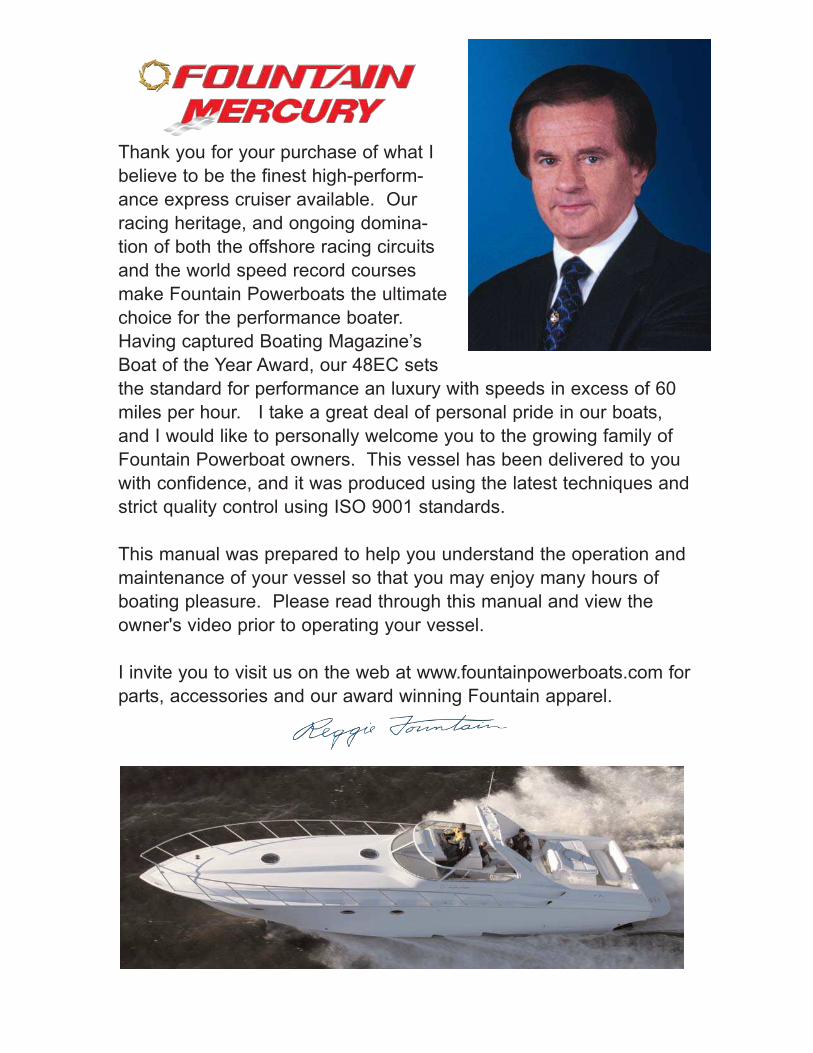
Thank you for your purchase of what I
believe to be the finest high-perform-
ance express cruiser available. Our
racing heritage, and ongoing domina-
tion of both the offshore racing circuits
and the world speed record courses
make Fountain Powerboats the ultimate
choice for the performance boater.
Having captured Boating Magazine’s
Boat of the Year Award, our 48EC sets
the standard for performance an luxury with speeds in excess of 60
miles per hour. I take a great deal of personal pride in our boats,
and I would like to personally welcome you to the growing family of
Fountain Powerboat owners. This vessel has been delivered to you
with confidence, and it was produced using the latest techniques and
strict quality control using ISO 9001 standards.
This manual was prepared to help you understand the operation and
maintenance of your vessel so that you may enjoy many hours of
boating pleasure. Please read through this manual and view the
owner's video prior to operating your vessel.
I invite you to visit us on the web at www.fountainpowerboats.com for
parts, accessories and our award winning Fountain apparel.
Expressed Written Warranty (2005-2006 Models) 1
Specifications 10
Hull Support for Trailers & Hoists 16
Quick Reference Layout Drawings/Photos 17
Equipment, Tools, Safety Equipment and Spare Items 27
Pre-boating Checks 28
Fueling and Fuel Systems 31
Hull Technology 33
Starting and Driving, Gauges and Instruments, Controls 43
Electrical Systems and Optional Equipment 49
Appearance and Care 62
Storage 65
Maintenance and Do It Yourself 66
Accessories & Apparel 71
Refurbishment & Upgrades 72
Troubleshooting 74
Electrical Schematic Diagrams 76
Table of Contents
FOUNTAIN POWERBOATS EXPRESS LIMITED
TRANSFERABLE WARRANTY
TERM: As used in this Agreement, the term "customer" shall be
deemed to include and to mean, without limitation, "consumer" and
"purchaser," as the context may require. The consequences to, and
the obligations of, each of the parties hereto shall be the same regard-
less of which of the above terms is used.
Note: FAILURE BY THE CUSTOMER OR THE DEALER TO RETURN
TO FOUNTAIN AN ORIGINAL COPY OF THE WARRANTY REGISTRA-
TION CARD, COMPLETED AND SIGNED BY THE CUSTOMER, WITHIN
THIRTY (30) DAYS FROM THE DATE OF PURCHASE BY THE CUS-
TOMER WILL VOID THIS WARRANTY. FOUNTAIN EXPRESSLY MAKES
THIS WARRANTY CONDITIONED ON THE RETURN OF THIS CARD TO
FOUNTAIN WITHIN THIRTY (30) DAYS OF PURCHASE. This warranty
gives the customer specific legal rights, and the customer may have other
rights. Rights varying from state to state shall be addressed by correspon-
ding Supplemental Dealer Sales Agreements.
Fountain Powerboat Dealers are not the agents of Fountain
Powerboats, Inc. NO FOUNTAIN DEALER IS AUTHORIZED TO ALTER
THE TERMS OF THIS WARRANTY IN ANY MANNER, EXCEPT WITH
THE WRITTEN PERMISSION OF THE PRESIDENT OF FOUNTAIN
POWERBOATS, INC.. THE CUSTOMER IS ADVISED TO DEMAND A
COPY OF THIS WRITTEN CONSENT BEFORE RELYING ON ANY REP-
RESENTATIONS OR PROMISES THAT MAY VARY THE TERMS OF THIS
WARRANTY. Fountain Powerboats, Inc. does not authorize its dealers
or any other persons to assume for the company any liability in con-
nection with this LIMITED EXPRESS WARRANTY or any liability or
expense incurred in the repairing or replacing of its products other
than those expressly authorized herein.
Fountain Powerboats warrants to the ORIGINAL RETAIL CUSTOMER each
new boat to be free from defects in materials and workmanship, provided
that the customer has maintained the same under normal, non-commercial
use and stored same in accordance with Fountain Powerboats' recommen-
dations.
Except as expressly indicated below, this warranty is for a term of one (1)
year beginning with the delivery of the boat to the original retail customer.
With respect to the structural portions of the hull and deck only, this warran-
ty is for a term of six (6) years beginning with the delivery of the boat to the
original retail customer. During this period, warranty repairs shall be made at
1
2
the selling dealer's store or service center or, at Fountain's discretion, at the
Fountain factory on Whichard's Beach Road in Washington, North Carolina.
This warranty may be transferred to a second or subsequent owner of the
boat provided that the second or subsequent owner notifies Fountain
Powerboats, Inc. in writing within thirty (30) days of the change of owner-
ship, by way of a completed warranty registration card. A transferred war-
ranty shall be limited in duration to the length of the original warranty period,
running from the date of delivery to the original retail customer, and the sec-
ond or subsequent owners shall be required to use the boat in a non-com-
mercial manner, and maintain and store the boat in accordance with
Fountain Powerboats' recommendations.
Transportation charges, if any, for Fountain Powerboats boats, to and from
the dealer's service center, or to and from the Fountain manufacturing plant
on Whichard's Beach Road in Washington, North Carolina, shall be the sole
responsibility of the customer. All repairs under the terms of this warranty
are subject to written authorization by factory-trained personnel whose deci-
sion shall be final.
The sales personnel or other employees of the selling Fountain dealer
are not authorized to make warranties concerning Fountain boats. No
other warranties are given beyond those set forth herein.
Please Note: In the event that a boat is on loan, has been leased, rent-
ed or continually used as a demo, the warranty will begin as soon as
one of these scenarios occurs. In the event that Fountain discovers
that this has occurred, the warranty will begin when Fountain, in its
sole discretion, has determined that the use began.
The warranty provided herein is in lieu of all other express warranties and
may not be extended or modified by anyone. Any implied warranties,
including any implied warranties of merchantability or fitness for a particular
purpose, are limited in duration to the period of the express warranty.
Repair and/or replacement is the exclusive remedy for all claims of breach
of warranty, both express and implied. Correction of non-conformities in the
manner and for the period of time as set forth above shall constitute fulfill-
ment of all Fountain Powerboats liability to the customer whether based on
contract, negligence or otherwise. Fountain shall not be liable for incidental,
consequential or special damages, such as but not limited to, damage to or
loss of other property, equipment, loss of profits, cost of purchased or
replacement goods, or claims of persons against the original customer. The
remedies of the customer set forth herein are exclusive and the liability of
Fountain shall not, except as expressly provided herein, exceed the price of
the goods upon which such liability is based.
This warranty does not apply to the following:
1) Engines, out-drives, transmission and propellers or any other compo-
nents of the powertrain or propulsion system. Custom-built Fountain
engines are also excluded from the warranty.
2) Equipment and accessories not manufactured by Fountain.
3) Cracking, crazing, discoloration or blistering of gel coat finishes, powder
coat finishes or paint finishes.
4) Carpet
5) Upholstery
6) Canvas
7) Windshield breakage, cracking or crazing.
8) Installation of engines by persons other than Fountain.
9) Costs for haul-out, launch, lift charges, towing, travel time charges, stor-
age charges, dockage, insurance costs, and inconvenience for loss of
time or income, etc.
10) The achievement of any particular performance or fuel consumption.
11) The cost of removing or replacing defective parts.
The following voids Fountain's warranty:
1) Subjecting the boat to accident, misuse, abuse or negligence.
2) Use of the boat for racing or engaging in a contest of speed or
endurance of any type or modification of the boat in any way other than
upon express instruction by Fountain.
3) Failure to perform periodic maintenance in accordance with Fountain
recommendations.
4) Damage caused by improper mating of the boat to the trailer. The
entire hull must be supported, which includes bunks that contour to
support the step hull on the entire running surface, especially directly
under the transom.
As an industry leader in research and development, Fountain Powerboats,
Inc. reserves the right to change specifications, features and prices of its
products without notification.
Warranty terms: Fountain's obligations under this express warranty and all
other implied warranties are limited solely to the repair and/or replacement
of any parts due to defective material or workmanship. The repair and/or
replacement work is to be done by an authorized Fountain dealer or by
Fountain within a reasonable time after the boat is delivered for repair. On
the day of sale, the customer and selling Fountain dealer must complete
and sign the warranty registration card, which is included with each boat.
The selling dealer must return the warranty registration card to Fountain
3
Powerboats within thirty (30) days of the date of sale. However, if the deal-
er fails to return the warranty registration card to Fountain within the time
period prescribed above, the customer's sole means of recovery shall be
against the Dealer.
The customer must bring the Fountain boat to the authorized servicing
Fountain dealer for such repair. No transportation charges will be paid by
Fountain to transport the boat to a dealer or the Fountain factory for repair.
Fountain is not responsible for engine removal and de-rigging. The cus-
tomer must maintain the boat in accordance with commonly accepted prac-
tice and Fountain recommendations. Fountain boats are intended primarily
for normal recreational and leisure time purposes and have not been
designed or manufactured for heavy, commercial use. Therefore, Fountain
is not liable for any consequential economic or physical damage resulting
from any breach of any written or implied warranty.
Procedures for warranty repairs and replacements:
1. Upon receipt of the express limited transferable warranty card, a
Fountain representative will be contacting you to determine where your
boat shall be serviced, should the need arise.
2. You will then be assigned an authorized servicing center to perform
your warranty work.
3. Should you wish or need to take your Fountain boat to a different
authorized servicing center for warranty work, please contact the
Fountain Customer Service by the methods described below.
4. The Fountain boat must be returned to the authorized servicing dealer
who has the primary responsibility to perform warranty repairs. In the
event the servicing dealer has ceased to do business, or you are travel-
ing or have moved to a different locale, work under the warranty may
be performed by any authorized Fountain dealer provided you have
pre-authorization from the factory. Except in the specific instances just
stated, your warranty work should be done by the authorized servicing
Fountain dealer. ANY AND ALL SERVICE QUESTIONS AND/OR
REQUESTS MUST BE MADE BY PHONE TO 252-975-2000 OR 252-
975-1132 OR BY MAIL TO FOUNTAIN'S PROPER MAILING
ADDRESS AS FOLLOWS:
Fountain Powerboats, Inc.
Attention: Customer Service
P.O. Box 457
Washington, NC 27889
4
5. The authorized servicing Fountain dealer will examine the boat to deter-
mine if, in its opinion, a warrantable defect exists. The servicing
Fountain dealer shall then report to Fountain whether a warrantable
defect appears to exist. Fountain, at its option and sole discretion, will
repair or authorize repair and/or replacement of all parts that are found
to be defective. For repairs performed other than at the Fountain facto-
ry in Washington, North Carolina, an authorization form will have to be
issued prior to any work performed. Prior written authorization from
Fountain is required. You will be asked to sign a warranty form to
assure Fountain that the warranty work has actually been performed to
your satisfaction.
Limitation on implied warranties:
ALL IMPLIED WARRANTIES, INCLUDING THE IMPLIED WARRANTIES
OF MERCHANTABILITY AND FITNESS FOR A PARTICULAR PURPOSE,
ARE LIMITED TO THE DURATION OF THIS EXPRESS WRITTEN LIMIT-
ED WARRANTY AND, LIKE THE EXPRESS WRITTEN WARRANTY, ARE
LIMITED TO REPAIR AND/OR REPLACEMENT AS THE SOLE MEANS
OF RECOVERY IN THE CASE OF BREACH.
Exclusion or limitation of damages:
Fountain will not be liable (a) for personal injury or property damage except
personal injury or property damage caused by Fountain's negligence; (b)
FOR ANY CONSEQUENTIAL ECONOMIC DAMAGES, DAMAGES TO
PROPERTY, DAMAGES FOR LOSS OF USE, LOSS OF TIME, LOSS OF
PROFITS, OR INCOME, OR ANY OTHER INCIDENTAL DAMAGES, OR
FOR ANY DAMAGES REGARDLESS OF THEIR NATURE CAUSED BY
THE CUSTOMER'S AND OR DEALER'S FAILURE TO FULFILL THEIR
RESPONSIBILITIES AS SET FORTH HEREIN.
IT IS EXPRESSLY UNDERSTOOD AND AGREED TO BY FOUNTAIN, THE
SELLING DEALER AND THE CUSTOMER, THAT ANY DISPUTE ARIS-
ING UNDER THE TERMS OF THIS WARRANTY WILL BE GOVERNED
BY THE APPLICABLE LAWS OF THE STATE OF NORTH CAROLINA
AND, EXCEPT WHERE SPECIFICALLY PROHIBITED OR LIMITED BY
THE LAWS OF A PARTICULAR STATE, THAT FOR ANY DISPUTE ARIS-
ING UNDER THIS WARRANTY, THE PROPER FORUM WILL BE THE
COURTS OF BEAUFORT COUNTY, NORTH CAROLINA OR, WHERE
APPROPRIATE, THE FEDERAL DISTRICT COURT FOR THE EASTERN
DISTRICT OF NORTH CAROLINA.
Note: Some states do not allow limitations as to the court in which a dis-
pute may be resolved, so the foregoing provision may not apply in all cases.
5
This limited warranty, along with the Dealer Sales Contract, constitute the
entire agreement and understanding between the customer and Fountain
with respect to the purchase and sale of boats. No agreement or statement
not contained in these agreements shall be binding upon Fountain as war-
ranty or otherwise, and neither this limited warranty nor the Sales Contract
shall be modified or amended unless it is in writing, executed by the
President of Fountain Powerboats and the customer. The foregoing terms
and conditions shall prevail notwithstanding any contrary terms and condi-
tions of any other submitted by the customer for the boats. In the event that
any of the above provisions should be held void by a state's court, all other
warranty provisions shall remain intact.
IMPORTANT SAFETY INSTRUCTIONS
WARNING
1. Read the owners manual and watch the owner's video prior to operat-
ing the boat to understand and comply with systems and safety rules.
2. Always check your gas gauge before leaving the dock.
3. Consult your engine information packet for recommendations and speci-
fications concerning fuels, lubrication, and boat & engine service inter-
vals.
4. Do not smoke while refueling. Fuel is very flammable.
5. Always maintain proper safety equipment before leaving the dock,
including, but not limited to an anchor, anchor line, at least one life vest
per person on board, a throw cushion with a 20' rope attached, a ships
bell, fire extinguisher, first aid kit, signal kit, spare oil, spare transmis-
sion fluid, and an assortment of miscellaneous tools.
6. Always check fluid levels and do an overall general inspection of the
engine compartment prior to starting the engines.
7. Change the oil and filters after every 20-30 hours of operation to help
prevent engine damage.
6
8. Always monitor water pressure gauges. Loss of water pressure
increases engine temperature and can cause severe damage to the
engine(s).
9. Always monitor oil pressure gauges. If the oil pressure drops, severe
engine damage could occur.
10. Check all bilge pumps before each outing, and before leaving your boat
moored to be sure they are fully functional, both in automatic and man-
ual modes.
11. Do not leave the boat unattended or uncovered for long periods of time,
or leave attached to mooring buoys in foul weather. Excess rain or
high winds may cause sinking. Once bilge pumps run down the bat-
tery, bilge pumps will no longer operate and the boat will sink if water
continues to enter the boat.
12. Review the performance report for proper trimming of the boat. Tests
are based on calm water operations. Rougher water requires substan-
tially different trim as shown in the owner's video manual. Usually as
the water gets rougher, the tabs will need to go down and the drives will
need to go in.
13. Always operate the blowers for at least 5 minutes before starting the
engine(s) to insure that all gas fumes are removed. Gas fumes are
heavier than air, and must be forced out of the bilge area.
14. Check the warning buzzer for sound to insure proper working order of
this warning device.
15. Always start the boat with the drives and tabs in the down position.
16. Always start the boat with the shifters in the neutral position.
17. Always allow the engine to idle in the neutral position, and to attain nor-
mal operating temperature before shifting gears to prevent engine and
gear damage.
18. Do not launch the boat if the drain plug is not installed.
19. Always wear your safety lanyard while under way.
20. Never trim the outdrive(s) out past 5.5 while on plane, and never inde-
pendently trim the outdrives to allow more than 2 marks of trim separa-
7
tion between the drives on the trim indicators.
21. Never trim the outdrive(s) in past 3 while on plane.
22. Always check forward visibility before getting on plane.
23. Always slow down before turning the boat.
24. Turning maneuvers are safer if done in calm water. Fast turns in any
conditions are dangerous.
25. Always look to the rear before turning. It is important to know what is
around you at all times.
26. Do not operate the boat so that it leaves the water. It may harm the
passengers. It will also cause over-rev related damage to the engine
and/or outdrives, as well as undue stress on the boat and it's internal
components.
27. Always be smooth, gentle and even with the throttles.
28. Never operate the boat at speeds that are beyond your capability, or the
capabilities of the boat.
29. Always check oil and fluids after use. See engine manual for fluids and
fluid levels.
30. Passenger safety is the boat owner/operators responsibility. Stop the
engines before using the transom area as a swim platform or when
swimmers are present in the area.
31. Do not operate this boat while under the influence of alcohol or drugs.
Alcohol and drugs severely reduce the ability to react, especially in sev-
eral different situations at once. Alcohol and drugs lead to incorrect
judgments of speed, distance and direction. Alcohol and drugs reduce
vision and the ability to fully comprehend emergency situations.
32. Always wash and flush engine(s) after use to keep corrosion damage to
a minimum especially in using the boat in salt water.
33. Always be sure to support the bottom of the boat, including directly
under the transom, when storing and/or trailering to prevent damage to
the bottom of the boat.
8
34. Review the engine owner's manual for care and maintenance of your
engine(s).
35. THIS IS NOT AN EXHAUSTIVE LIST. Always use common sense
when operating your boat and seek proper guidance from qualified
mechanics when making repairs.
By signing this warranty card the customer acknowledges that he or she 1)
has viewed the Fountain Video Owner's Manual, 2) fully understands safe
boating operation and every aspect of his/her Fountain boat. The customer
also verifies that he/she has reviewed the Fountain performance report with
the dealer and understands the proper trim settings for tabs and drives for
all speeds, in all conditions, and while turning. The customer also verifies
that the dealer has fully demonstrated this boat to him/her on the water and
has demonstrated all systems and proper trimming of the drives and trim
tabs for all sea conditions. The customer acknowledges that he/she has
been informed of all potential hazards which can occur while boating. The
customer also acknowledges that this boat should not be operated if any of
the following are true: a) rough water, b) he/she is under the influence of
drugs or alcohol, c) in severe weather, darkness, fog or low visibility. The
customer acknowledges that he/she should wear their safety lanyard and
life vest at all times and never turn the boat at an unsafe speed. The cus-
tomer also acknowledges that he/she has read, understands, and agrees to
abide by all of the important safety information on this warranty card.
This warranty registration must be completed and received by Fountain
Powerboats within 30 days of purchase. Failure to do so will result in the
warranty beginning on the date of delivery to the selling dealer. By signing,
customer acknowledged having read and understood Fountain's Boat
Warranty.
9
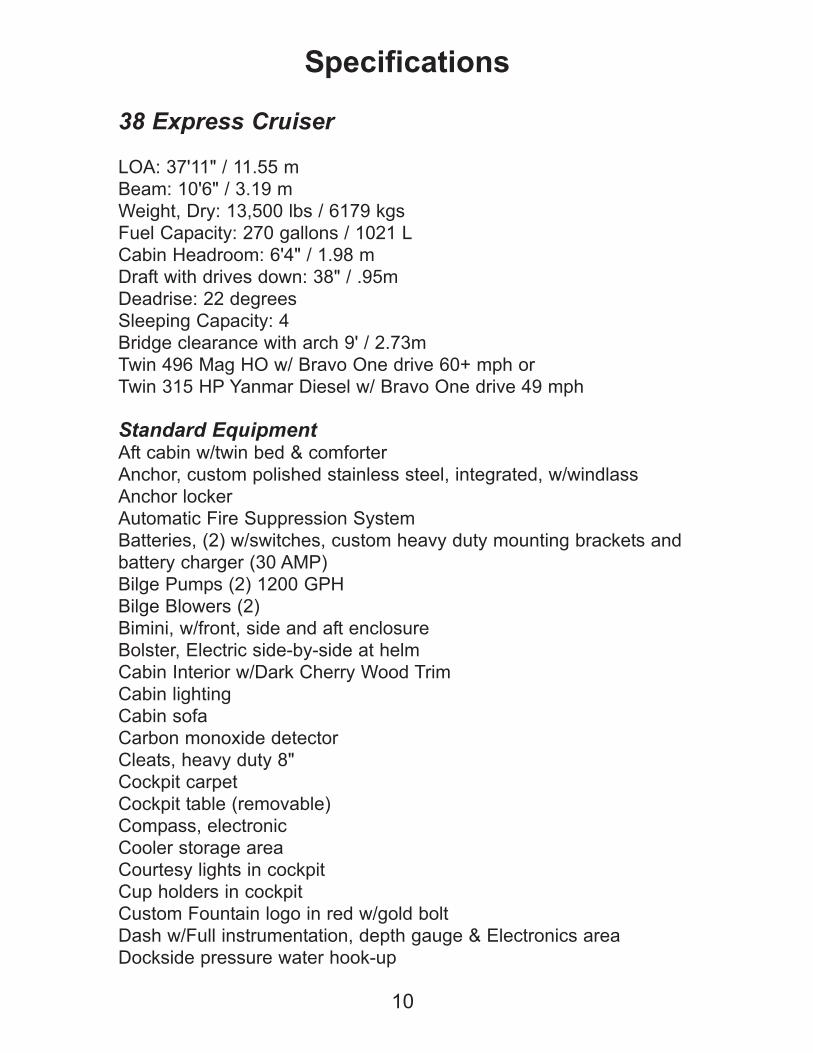
38 Express Cruiser
LOA: 37'11" / 11.55 m
Beam: 10'6" / 3.19 m
Weight, Dry: 13,500 lbs / 6179 kgs
Fuel Capacity: 270 gallons / 1021 L
Cabin Headroom: 6'4" / 1.98 m
Draft with drives down: 38" / .95m
Deadrise: 22 degrees
Sleeping Capacity: 4
Bridge clearance with arch 9' / 2.73m
Twin 496 Mag HO w/ Bravo One drive 60+ mph or
Twin 315 HP Yanmar Diesel w/ Bravo One drive 49 mph
Standard EquipmentAft cabin w/twin bed & comforter
Anchor, custom polished stainless steel, integrated, w/windlass
Anchor locker
Automatic Fire Suppression System
Batteries, (2) w/switches, custom heavy duty mounting brackets and
battery charger (30 AMP)
Bilge Pumps (2) 1200 GPH
Bilge Blowers (2)
Bimini, w/front, side and aft enclosure
Bolster, Electric side-by-side at helm
Cabin Interior w/Dark Cherry Wood Trim
Cabin lighting
Cabin sofa
Carbon monoxide detector
Cleats, heavy duty 8"
Cockpit carpet
Cockpit table (removable)
Compass, electronic
Cooler storage area
Courtesy lights in cockpit
Cup holders in cockpit
Custom Fountain logo in red w/gold bolt
Dash w/Full instrumentation, depth gauge & Electronics area
Dockside pressure water hook-up
10
Specifications

Engine hatch, motorized
Engine room lights
Fender storage
Forward cabin w/V-berth w/comforter & pillows, dresser and hanging
closet
Fresh water, 50 gallon w/hot water heater
Fuel tanks, heavy duty, baffled, 3/16" thick aluminum; foamed,
glassed and bolted in position w/stainless steel pickups, 270 gallon
total capacity
Galley w/sink, microwave & refrigerator/freezer
Hanging locker, cedar lined
Head, enclosed fiberglass, vacu-flush, stand up w/shower
Horns, electric
Hot water heater, 6 gallons
Navigation lights
Positive lift hull, twin step, Generation III
Radar arch w/cockpit lighting
Reading lights in forward and aft cabins
Shore power
Steering, heavy duty hydraulic w/dual pumps
Stereo w/CD and remote
Swim platform w/transom shower, & swim ladder
TV/VCR combination
Table in cabin, removable
Throttle w/drive trim on handle
Trim tab indicators, mechanical
Trim tabs, heavy duty hydraulic, offshore hi-performance
Wet bar in cockpit w/Storage, pressurized sink & ice maker
Windlass
Windshield, wrap-around
11
Specifications
12
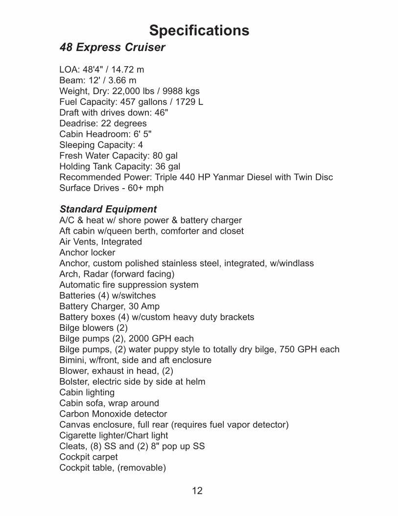
Specifications48 Express Cruiser
LOA: 48'4" / 14.72 m
Beam: 12' / 3.66 m
Weight, Dry: 22,000 lbs / 9988 kgs
Fuel Capacity: 457 gallons / 1729 L
Draft with drives down: 46"
Deadrise: 22 degrees
Cabin Headroom: 6' 5"
Sleeping Capacity: 4
Fresh Water Capacity: 80 gal
Holding Tank Capacity: 36 gal
Recommended Power: Triple 440 HP Yanmar Diesel with Twin Disc
Surface Drives - 60+ mph
Standard EquipmentA/C & heat w/ shore power & battery charger
Aft cabin w/queen berth, comforter and closet
Air Vents, Integrated
Anchor locker
Anchor, custom polished stainless steel, integrated, w/windlass
Arch, Radar (forward facing)
Automatic fire suppression system
Batteries (4) w/switches
Battery Charger, 30 Amp
Battery boxes (4) w/custom heavy duty brackets
Bilge blowers (2)
Bilge pumps (2), 2000 GPH each
Bilge pumps, (2) water puppy style to totally dry bilge, 750 GPH each
Bimini, w/front, side and aft enclosure
Blower, exhaust in head, (2)
Bolster, electric side by side at helm
Cabin lighting
Cabin sofa, wrap around
Carbon Monoxide detector
Canvas enclosure, full rear (requires fuel vapor detector)
Cigarette lighter/Chart light
Cleats, (8) SS and (2) 8" pop up SS
Cockpit carpet
Cockpit table, (removable)
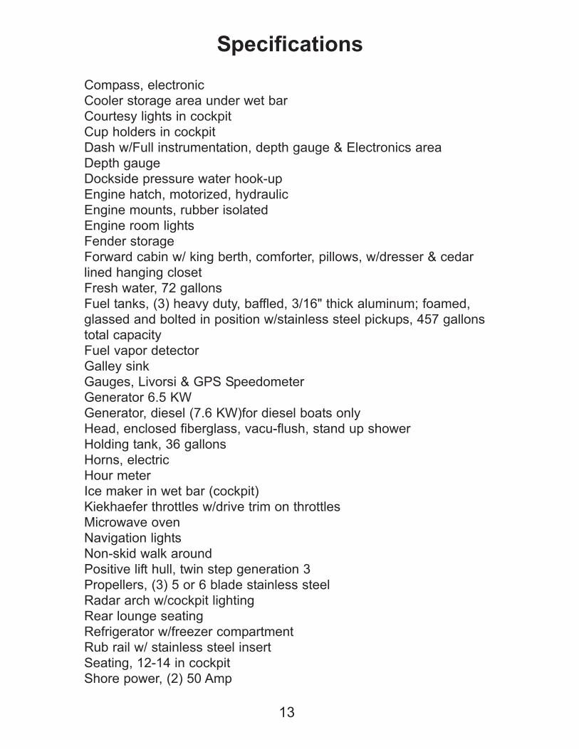
Compass, electronic
Cooler storage area under wet bar
Courtesy lights in cockpit
Cup holders in cockpit
Dash w/Full instrumentation, depth gauge & Electronics area
Depth gauge
Dockside pressure water hook-up
Engine hatch, motorized, hydraulic
Engine mounts, rubber isolated
Engine room lights
Fender storage
Forward cabin w/ king berth, comforter, pillows, w/dresser & cedar
lined hanging closet
Fresh water, 72 gallons
Fuel tanks, (3) heavy duty, baffled, 3/16" thick aluminum; foamed,
glassed and bolted in position w/stainless steel pickups, 457 gallons
total capacity
Fuel vapor detector
Galley sink
Gauges, Livorsi & GPS Speedometer
Generator 6.5 KW
Generator, diesel (7.6 KW)for diesel boats only
Head, enclosed fiberglass, vacu-flush, stand up shower
Holding tank, 36 gallons
Horns, electric
Hour meter
Ice maker in wet bar (cockpit)
Kiekhaefer throttles w/drive trim on throttles
Microwave oven
Navigation lights
Non-skid walk around
Positive lift hull, twin step generation 3
Propellers, (3) 5 or 6 blade stainless steel
Radar arch w/cockpit lighting
Rear lounge seating
Refrigerator w/freezer compartment
Rub rail w/ stainless steel insert
Seating, 12-14 in cockpit
Shore power, (2) 50 Amp
13
Specifications
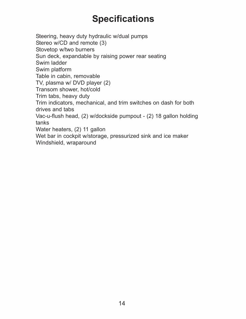
Steering, heavy duty hydraulic w/dual pumps
Stereo w/CD and remote (3)
Stovetop w/two burners
Sun deck, expandable by raising power rear seating
Swim ladder
Swim platform
Table in cabin, removable
TV, plasma w/ DVD player (2)
Transom shower, hot/cold
Trim tabs, heavy duty
Trim indicators, mechanical, and trim switches on dash for both
drives and tabs
Vac-u-flush head, (2) w/dockside pumpout - (2) 18 gallon holding
tanks
Water heaters, (2) 11 gallon
Wet bar in cockpit w/storage, pressurized sink and ice maker
Windshield, wraparound
14
Specifications
15
Specifications
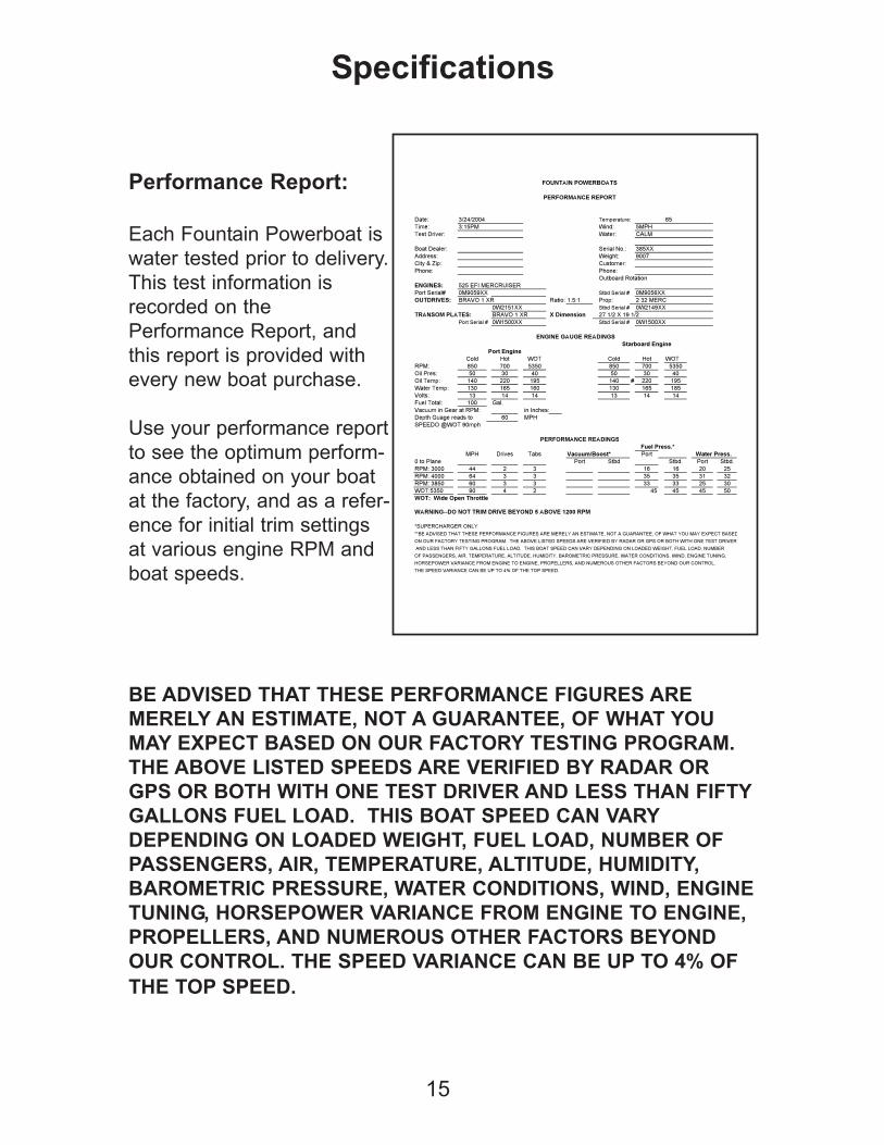
Performance Report:
Each Fountain Powerboat is
water tested prior to delivery.
This test information is
recorded on the
Performance Report, and
this report is provided with
every new boat purchase.
Use your performance report
to see the optimum perform-
ance obtained on your boat
at the factory, and as a refer-
ence for initial trim settings
at various engine RPM and
boat speeds.
BE ADVISED THAT THESE PERFORMANCE FIGURES ARE
MERELY AN ESTIMATE, NOT A GUARANTEE, OF WHAT YOU
MAY EXPECT BASED ON OUR FACTORY TESTING PROGRAM.
THE ABOVE LISTED SPEEDS ARE VERIFIED BY RADAR OR
GPS OR BOTH WITH ONE TEST DRIVER AND LESS THAN FIFTY
GALLONS FUEL LOAD. THIS BOAT SPEED CAN VARY
DEPENDING ON LOADED WEIGHT, FUEL LOAD, NUMBER OF
PASSENGERS, AIR, TEMPERATURE, ALTITUDE, HUMIDITY,
BAROMETRIC PRESSURE, WATER CONDITIONS, WIND, ENGINE
TUNING, HORSEPOWER VARIANCE FROM ENGINE TO ENGINE,
PROPELLERS, AND NUMEROUS OTHER FACTORS BEYOND
OUR CONTROL. THE SPEED VARIANCE CAN BE UP TO 4% OF
THE TOP SPEED.
FOUNTAIN POWERBOATS
PERFORMANCE REPORT
Date: 3/24/2004 Temperature: 65
Time: 3:15PM Wind: 5MPH
Test Driver: Water: CALM
Boat Dealer: Serial No.: 385XX
Address: Weight: 9007
City & Zip: Customer:
Phone: Phone:
Outboard Rotation
ENGINES: 525 EFI MERCRUISER
Port Serial# 0M9059XX Stbd Serial # 0M9056XX
OUTDRIVES: BRAVO 1 XR Ratio: 1.5:1 Prop: 2 32 MERC
0W2151XX Stbd Serial # 0W2149XX
TRANSOM PLATES: BRAVO 1 XR X Dimension 27 1/2 X 19 1/2
Port Serial # 0W1500XX Stbd Serial # 0W1500XX
ENGINE GAUGE READINGS
Starboard Engine
Port Engine
Cold Hot WOT Cold Hot WOT
RPM: 850 700 5350 850 700 5350
Oil Pres: 50 30 40 50 30 40
Oil Temp: 140 220 195 140 # 220 195
Water Temp: 130 165 160 130 165 185
Volts: 13 14 14 13 14 14
Fuel Total: 100 Gal.
Vacuum in Gear at RPM: in Inches:
Depth Guage reads to 60 MPH
SPEEDO @WOT 90mph
PERFORMANCE READINGS
Fuel Press.*
MPH Drives Tabs Vacuum/Boost* Port Water Press.
0 to Plane Port Stbd Stbd. Port Stbd.
RPM: 3000 44 2 3 16 16 20 25
RPM: 4000 64 3 3 35 35 31 32
RPM: 3850 60 3 3 33 33 25 30
WOT:5350 90 4 2 45 45 45 50
WOT: Wide Open Throttle
WARNING--DO NOT TRIM DRIVE BEYOND 5 ABOVE 1200 RPM
*SUPERCHARGER ONLY
**BE ADVISED THAT THESE PERFORMANCE FIGURES ARE MERELY AN ESTIMATE, NOT A GUARANTEE, OF WHAT YOU MAY EXPECT BASED
ON OUR FACTORY TESTING PROGRAM. THE ABOVE LISTED SPEEDS ARE VERIFIED BY RADAR OR GPS OR BOTH WITH ONE TEST DRIVER
AND LESS THAN FIFTY GALLONS FUEL LOAD. THIS BOAT SPEED CAN VARY DEPENDING ON LOADED WEIGHT, FUEL LOAD, NUMBER
OF PASSENGERS, AIR, TEMPERATURE, ALTITUDE, HUMIDITY, BAROMETRIC PRESSURE, WATER CONDITIONS, WIND, ENGINE TUNING,
HORSEPOWER VARIANCE FROM ENGINE TO ENGINE, PROPELLERS, AND NUMEROUS OTHER FACTORS BEYOND OUR CONTROL.
THE SPEED VARIANCE CAN BE UP TO 4% OF THE TOP SPEED.
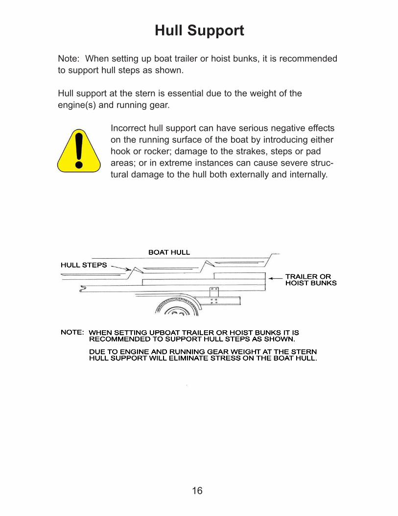
Note: When setting up boat trailer or hoist bunks, it is recommended
to support hull steps as shown.
Hull support at the stern is essential due to the weight of the
engine(s) and running gear.
Incorrect hull support can have serious negative effects
on the running surface of the boat by introducing either
hook or rocker; damage to the strakes, steps or pad
areas; or in extreme instances can cause severe struc-
tural damage to the hull both externally and internally.
16
Hull Support
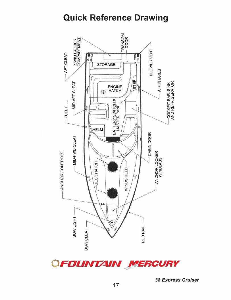
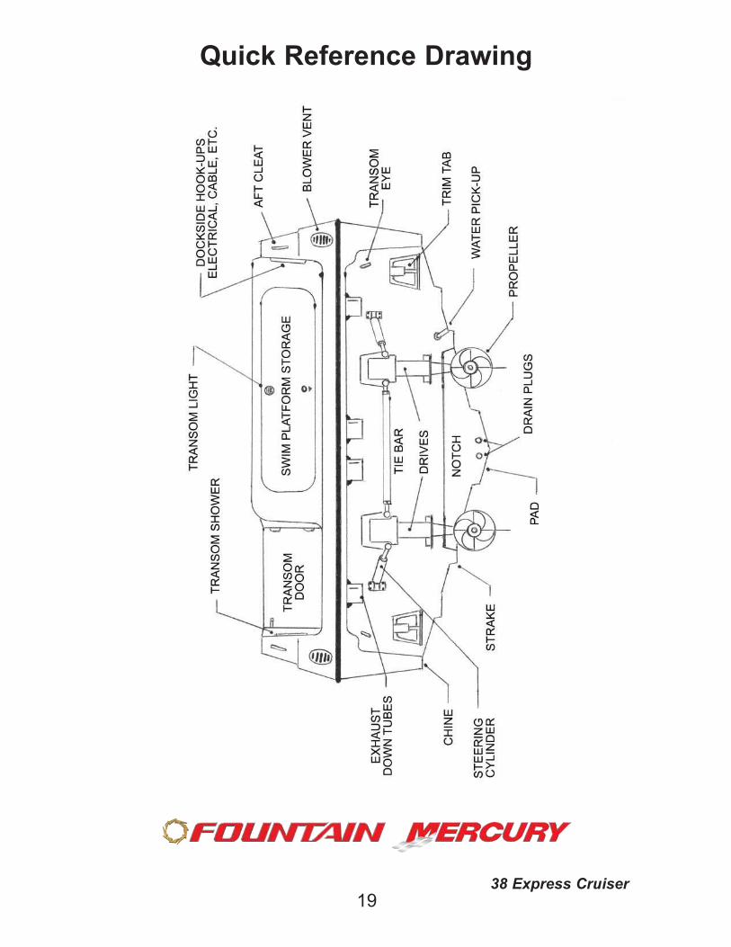
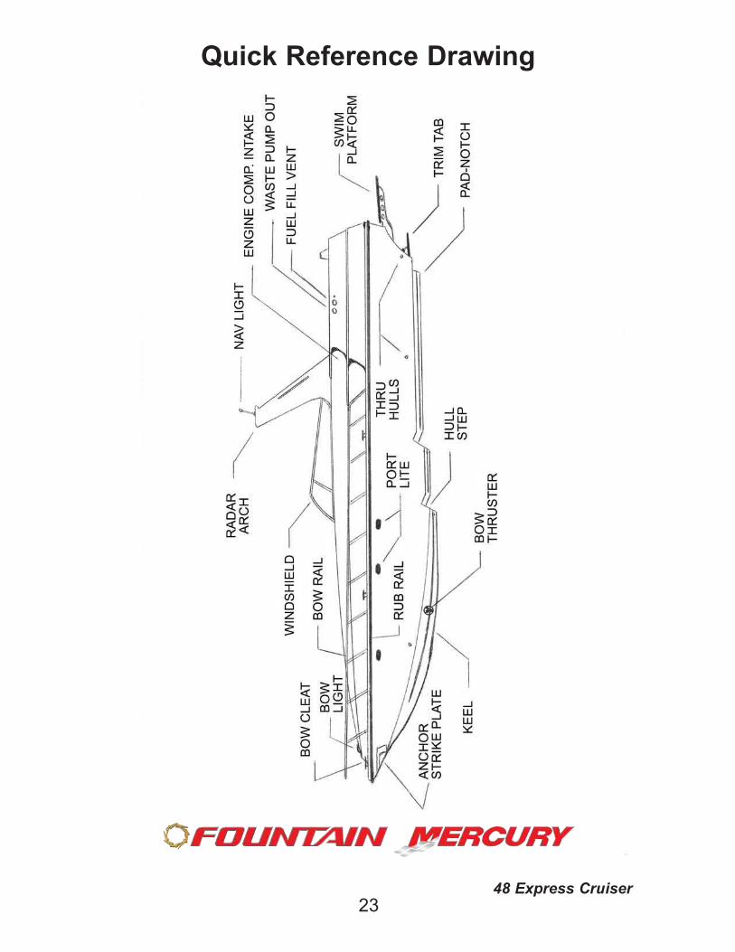
Quick Reference Drawing
1738 Express Cruiser
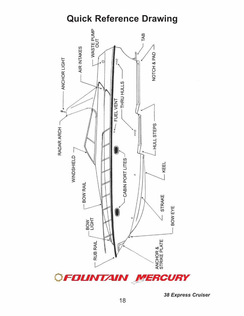
Quick Reference Drawing
1838 Express Cruiser
Quick Reference Drawing
1938 Express Cruiser
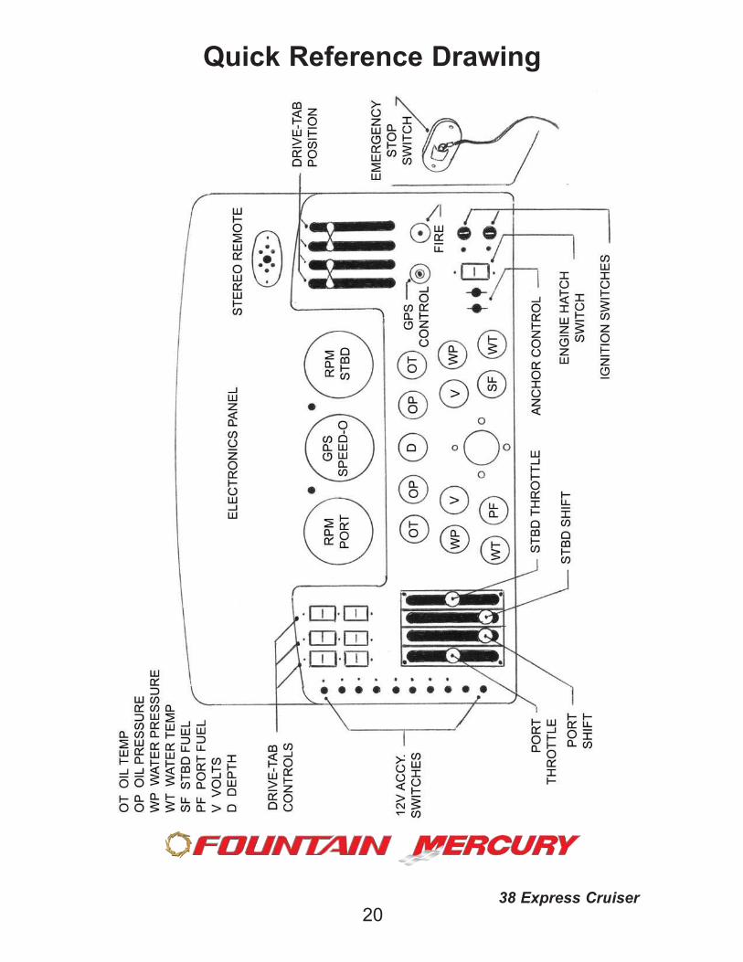
Quick Reference Drawing
2038 Express Cruiser
Quick Reference Drawing
2138 Express Cruiser
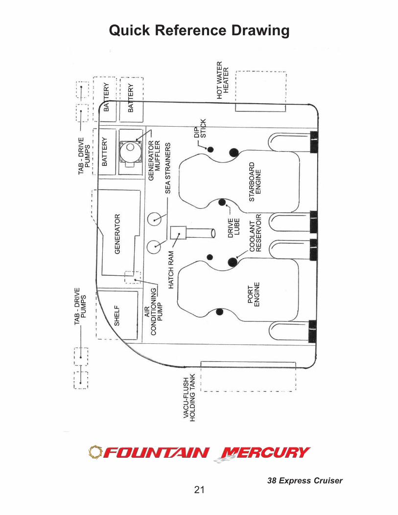
Quick Reference Drawing
2248 Express Cruiser
Quick Reference Drawing
2348 Express Cruiser
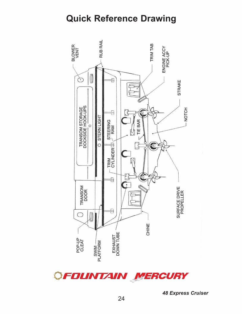
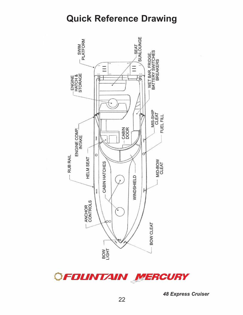
Quick Reference Drawing
2448 Express Cruiser
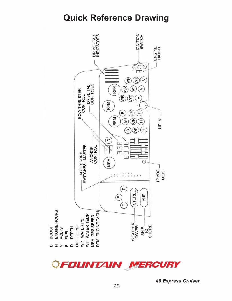
Quick Reference Drawing
2548 Express Cruiser
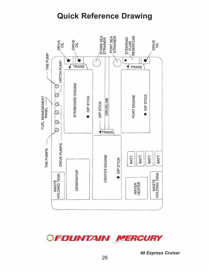
Quick Reference Drawing
2648 Express Cruiser
27
Equipment, Tools, Safety Equipment and Spare Items
These items are recommended to carry on your vessel for maintenance or
minor trouble. Safety equipment for some items is required by law.
Tool Chest
Screwdriver (Phillips & Flat blade)
Pliers (Regular, Channel Loc, Vice Grip)
Wrench Set (Open End, Box, Allen, Adjustable, Propeller Wrench)
Socket Set (Metric & Standard)
Hammer
Jumper Cables (Standard Jumper plug cables provided with vessel)
Electrical Tape
Assorted Fasteners (Cable Ties, Electrical Connectors, Crimping tool,
Screws, Nuts, Etc.)
Grease Gun and Oils
Safety Equipment
Fire Extinguishers (Type ABC)
Personal Flotation Devices (Life jackets, 1 per person)
Throwable Flotation Device
Signaling Device (Ships Bell or Horn)
VHF Radio
First Aid Kit
Flashlight and Batteries
Anchor and Line
Dock Lines
Appropriate Charts for your Cruising Area
Miscellaneous Items
Spare Propellers (Thrust washers, Prop nuts and Lock washers)
Extra Engine Belts
Engine Oil (Recommended mfg weights)
Fuel and Oil Filters
Replacement Light Bulbs
Extra Spark Plugs
Assorted Fuses
We recommend that you strongly consider membership in a national
towing service. This can dramatically reduce your costs of any towing
service if it is ever needed on your vessel.
See Quick Reference Drawings for locating equipment and acces-sories
Before launching vessel, perform a visual inspection. Walk around,check hull and deck for any damage from trailer or docking, from theroad or from your last trip. Check for damaged propellers and oilleaks from lower units, steering hoses, steering rams and trim tabs.Do not launch or run the vessel until questionable damage isrepaired.
If boating at night, check navigation lights for proper operation.
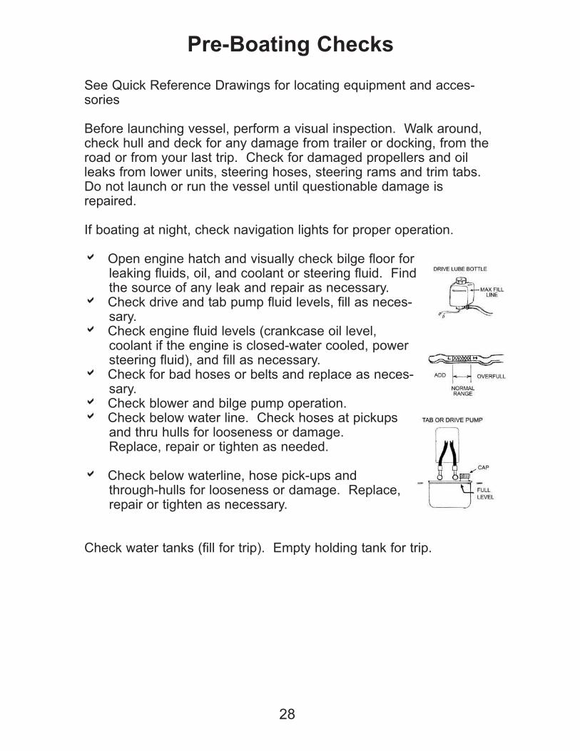
a Open engine hatch and visually check bilge floor forleaking fluids, oil, and coolant or steering fluid. Findthe source of any leak and repair as necessary.
a Check drive and tab pump fluid levels, fill as neces-sary.
a Check engine fluid levels (crankcase oil level,coolant if the engine is closed-water cooled, powersteering fluid), and fill as necessary.
a Check for bad hoses or belts and replace as neces-sary.
a Check blower and bilge pump operation.a Check below water line. Check hoses at pickups
and thru hulls for looseness or damage.Replace, repair or tighten as needed.
a Check below waterline, hose pick-ups andthrough-hulls for looseness or damage. Replace,repair or tighten as necessary.
Check water tanks (fill for trip). Empty holding tank for trip.
28
Pre-Boating Checks
29
Pre-Boating Checks
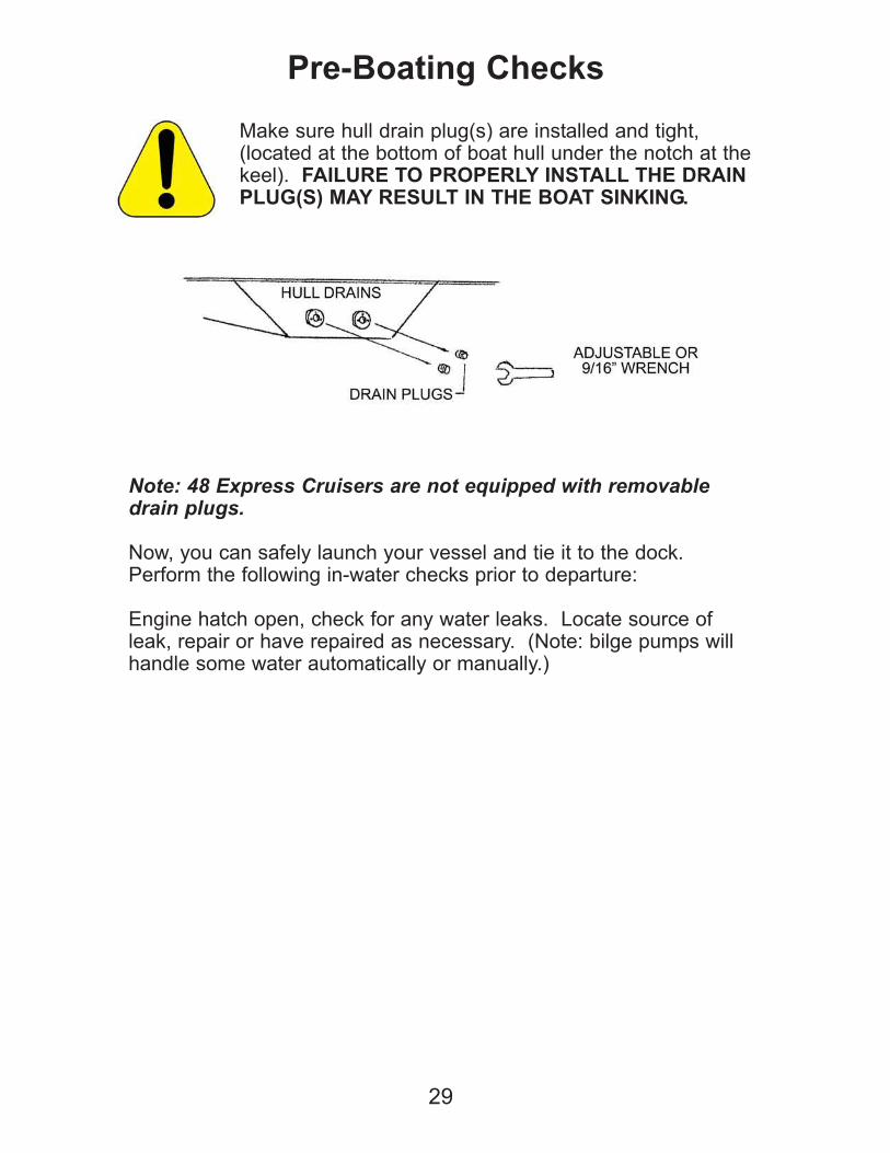
Make sure hull drain plug(s) are installed and tight,(located at the bottom of boat hull under the notch at thekeel). FAILURE TO PROPERLY INSTALL THE DRAINPLUG(S) MAY RESULT IN THE BOAT SINKING.
Note: 48 Express Cruisers are not equipped with removabledrain plugs.
Now, you can safely launch your vessel and tie it to the dock.Perform the following in-water checks prior to departure:
Engine hatch open, check for any water leaks. Locate source ofleak, repair or have repaired as necessary. (Note: bilge pumps willhandle some water automatically or manually.)
Fuel System
Everyone who owns or operates a boat must practice fire safety.Each year, boat fires and explosions injure hundreds of individualsand cause millions of dollars in property damage. Many of theseaccidents can be prevented.
Be alert to your boat's fuel system. Over time, fuel fittings and hoseswear out. Inspect these fittings and hoses regularly, especially nearthe engine where heat and vibration can accelerate deterioration.
Schedule regular engine and exhaust system maintenanceinspections by experienced and trained technicians.Inspect fuel systems annually, particularly hoses, connectionsand tank surfaces. Use only USCG-approved fuel hoses.Before fueling, shut down engines and auxiliary equipment andall electrical equipment. Also, close hatches and doors on board.Do not allow equipment or gear to contact fuel system compo-nents. Monitor side storage areas where fill and vent hoses arelocated.Do not store portable fuel tanks in enclosed areas, includingengine room compartment (even though it may be "ventilated").Ensure that all blowers and hoses are operational and intact.Verify good airflow at the vent on the boat.Take a boating safety course and learn the correct type and useof a fire extinguisher aboard the boat. Have the appropriate fireextinguisher on board at all times.Make sure your passengers know the location of all fire extin-guishers on board.
30
Pre-Boating Checks
Fueling Procedure as Follows:
Refer to the owner's manual for your engines to determine the appro-
priate fuel grade for use in your boat.
a Close all fuel valves and shut off battery
switches before fueling.
a Do not smoke.
a Fill fuel tanks desired through proper fills. Tanks are as full as
possible if fuel comes out of the vents. (Note, hose off boat of spilled
fuel, and let the boat air out as necessary to eliminate any fuel
vapors.)
a Open desired valve(s) for tank(s) you wish to run. Check bilge by
smell for leaks or fumes. Turn off valve(s) if any leaks are present,
repair or have repaired immediately. See engine compartment refer-
ence drawing for location.
a Operate the bilge blowers for at least 4 minutes before starting
your inboard or sterndrive engine.
31
Fueling
BE SURE TO CONFIRM DIESEL OR GASOLINE
PRIOR TO FILLING YOUR BOAT WITH FUEL.
CROSS-CONTAMINATION OF GASOLINE OR
DIESEL FUEL CAN DAMAGE YOUR ENGINE, AND
MAY VOID YOUR WARRANTY

Warning: Fuel is a dangerous explosion
and fire hazard. No smoking or sparks
during fueling operations.
Warning: Do not start engine(s); turn on
batteries, or electrical devices if fuel leaks
or fumes are present.
32
Fueling
33
Hull Technology
HULL STEP TECHNOLOGY HAS CHANGED THE WAY WE NEED
TO DRIVE!
WHILE SMOOTH OPERATION HAS ALWAYS BEEN THE KEY TO
SAFE HIGH SPEED OPERATION, BEING SMOOTH AND USING
COMMON SENSE IS EVEN MORE CRITICAL WITH TODAY’S
FASTER, MORE TECHNOLOGICALLY ADVANCED HULL
DESIGNS.
THE NEW TECHNOLOGY HAS ALLOWED LARGER, LONGER,
HEAVIER BOATS TO TRAVEL AT MUCH FASTER SPEEDS, WITH
STANDARD HORSEPOWER. THE SIMPLE FACT IS THAT
THINGS HAPPEN MUCH FASTER AT HIGHER RATES OF
SPEED, AND LARGER BOATS SIMPLY CARRY MORE ENERGY
ONCE IN MOTION.
INCORRECT TRIM SETTINGS OR IRRATIC TURNING MANEU-
VERS, WHILE STILL DANGEROUS AT SLOW SPEEDS, CAN BE
DISASTROUS AT HIGH SPEEDS.
AT HIGHER RATES OF SPEED, THERE IS LITTLE OR NO WARN-
ING BEFORE THE BOAT REACTS TO RAPID TURNS OR INCOR-
RECT AND/OR ABRUPT TRIM CHANGES.
COMMON SENSE IS YOUR BEST DEFENSE!
NONE OF US WOULD TAKE A NEW CORVETTE OUT, RUN IT UP
TO 60MPH, GRAB THE WHEEL AND MAKE AN ABRUPT 180
DEGREE TURN ON THE WHEEL. THE SAME CONCEPT
APPLIES TO BOATS.
KNOW YOUR LIMITATIONS, AS WELL AS THE LIMITATIONS OF
THE EQUIPMENT, AND DRIVE WITHIN THEM.
34
Hull Technology
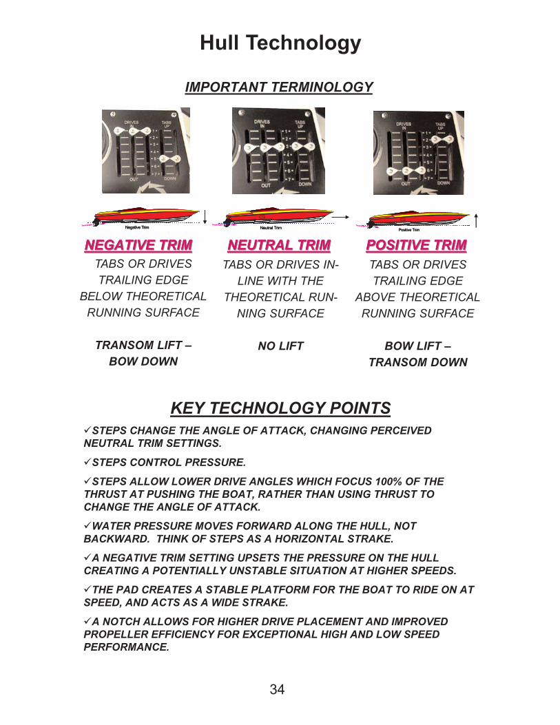
IMPORTANT TERMINOLOGY
NEGATIVE TRIMNEGATIVE TRIM NEUTRAL TRIMNEUTRAL TRIM POSITIVE TRIMPOSITIVE TRIMNEGATIVE TRIMNEGATIVE TRIM NEUTRAL TRIMNEUTRAL TRIM POSITIVE TRIMPOSITIVE TRIM
Thrust Angle
Negative Trim
CG
Thrust Angle
Negative Trim
CG
Thrust Angle
Negative Trim
CG
Neutral TrimThrust Angle
CG
Neutral TrimThrust Angle
CG
Neutral TrimThrust Angle
CG
Positive Trim
CG
Thrust Angle
Positive Trim
CG
Thrust Angle
Positive Trim
CG
Thrust Angle
TABS OR DRIVES
TRAILING EDGE
BELOW THEORETICAL
RUNNING SURFACE
TRANSOM LIFT –
BOW DOWN
TABS OR DRIVES IN-
LINE WITH THE
THEORETICAL RUN-
NING SURFACE
NO LIFT
TABS OR DRIVES
TRAILING EDGE
ABOVE THEORETICAL
RUNNING SURFACE
BOW LIFT –
TRANSOM DOWN
KEY TECHNOLOGY POINTS
STEPS CHANGE THE ANGLE OF ATTACK, CHANGING PERCEIVED
NEUTRAL TRIM SETTINGS.
STEPS CONTROL PRESSURE.
STEPS ALLOW LOWER DRIVE ANGLES WHICH FOCUS 100% OF THE
THRUST AT PUSHING THE BOAT, RATHER THAN USING THRUST TO
CHANGE THE ANGLE OF ATTACK.
WATER PRESSURE MOVES FORWARD ALONG THE HULL, NOT
BACKWARD. THINK OF STEPS AS A HORIZONTAL STRAKE.
A NEGATIVE TRIM SETTING UPSETS THE PRESSURE ON THE HULL
CREATING A POTENTIALLY UNSTABLE SITUATION AT HIGHER SPEEDS.
THE PAD CREATES A STABLE PLATFORM FOR THE BOAT TO RIDE ON AT
SPEED, AND ACTS AS A WIDE STRAKE.
A NOTCH ALLOWS FOR HIGHER DRIVE PLACEMENT AND IMPROVED
PROPELLER EFFICIENCY FOR EXCEPTIONAL HIGH AND LOW SPEED
PERFORMANCE.
Perceived Angle of A ttack
2.00°
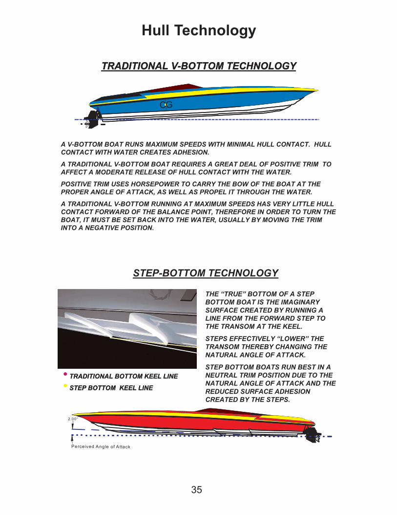
THE “TRUE” BOTTOM OF A STEP
BOTTOM BOAT IS THE IMAGINARY
SURFACE CREATED BY RUNNING A
LINE FROM THE FORWARD STEP TO
THE TRANSOM AT THE KEEL.
STEPS EFFECTIVELY “LOWER” THE
TRANSOM THEREBY CHANGING THE
NATURAL ANGLE OF ATTACK.
STEP BOTTOM BOATS RUN BEST IN A
NEUTRAL TRIM POSITION DUE TO THE
NATURAL ANGLE OF ATTACK AND THE
REDUCED SUFRACE ADHESION
CREATED BY THE STEPS.
� TRADITIONAL BOTTOM KEEL LINE
� STEP BOTTOM KEEL LINE
� TRADITIONAL BOTTOM KEEL LINE
� STEP BOTTOM KEEL LINE
35
Hull Technology
CG
TRADITIONAL V-BOTTOM TECHNOLOGY
CG
TRADITIONAL V-BOTTOM TECHNOLOGY
STEP-BOTTOM TECHNOLOGY
A V-BOTTOM BOAT RUNS MAXIMUM SPEEDS WITH MINIMAL HULL CONTACT. HULL
CONTACT WITH WATER CREATES ADHESION.
A TRADITIONAL V-BOTTOM BOAT REQUIRES A GREAT DEAL OF POSITIVE TRIM TO
AFFECT A MODERATE RELEASE OF HULL CONTACT WITH THE WATER.
POSITIVE TRIM USES HORSEPOWER TO CARRY THE BOW OF THE BOAT AT THE
PROPER ANGLE OF ATTACK, AS WELL AS PROPEL IT THROUGH THE WATER.
A TRADITIONAL V-BOTTOM RUNNING AT MAXIMUM SPEEDS HAS VERY LITTLE HULL
CONTACT FORWARD OF THE BALANCE POINT, THEREFORE IN ORDER TO TURN THE
BOAT, IT MUST BE SET BACK INTO THE WATER, USUALLY BY MOVING THE TRIM
INTO A NEGATIVE POSITION.
THE “TRUE” BOTTOM OF A STEP
BOTTOM BOAT IS THE IMAGINARY
SURFACE CREATED BY RUNNING A
LINE FROM THE FORWARD STEP TO
THE TRANSOM AT THE KEEL.
STEPS EFFECTIVELY “LOWER” THE
TRANSOM THEREBY CHANGING THE
NATURAL ANGLE OF ATTACK.
STEP BOTTOM BOATS RUN BEST IN A
NEUTRAL TRIM POSITION DUE TO THE
NATURAL ANGLE OF ATTACK AND THE
REDUCED SURFACE ADHESION
CREATED BY THE STEPS.
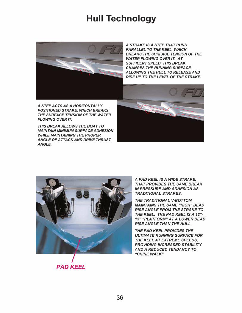
A STRAKE IS A STEP THAT RUNS
PARALEL TO THE KEEL, WHICH BREAKS
THE SURFACE TENSION OF THE WATER
FLOWING OVER IT. AT SUFFICENT
SPEED, THIS BREAK CHANGES THE
RUNNING SURFACE ALLOWING THE
HULL TO RELEASE AND RIDE UP TO THE
LEVEL OF THE STRAKE.
36
Hull Technology
A STEP ACTS AS A HORIZONTALLY
POSITIONED STRAKE, WHICH BREAKS
THE SURFACE TENSION OF THE WATER
FLOWING OVER IT.
THIS BREAK ALLOWS THE BOAT TO
MAINTAIN MINIMUM SURFACE ADHESION
WHILE MAINTAING THE PROPER ANGLE
OF ATTACK AND DRIVE THRUST ANGLE.
A STRAKE IS A STEP THAT RUNS
PARALELL TO THE KEEL, WHICH
BREAKS THE SURFACE TENSION OF THE
WATER FLOWING OVER IT. AT
SUFFICENT SPEED, THIS BREAK
CHANGES THE RUNNING SURFACE
ALLOWING THE HULL TO RELEASE AND
RIDE UP TO THE LEVEL OF THE STRAKE.
PAD KEELPAD KEEL
A PAD KEEL IS A WIDE STRAKE,
THAT PROVIDES THE SAME BREAK
IN PRESSURE AND ADHESION AS
TRADITIONAL STRAKES.
THE TRADITIONAL V-BOTTOM
MAINTAINS THE SAME “HIGH” DEAD
RISE ANGLE FROM THE STRAKE TO
THE KEEL. THE PAD KEEL IS A 12”-
15” “PLATFORM” AT A LOWER DEAD
RISE ANGLE THAN THE HULL.
THE PAD KEEL PROVIDES THE
ULTIMATE RUNNING SURFACE FOR
THE KEEL AT EXTREEM SPEEDS,
PROVIDING INCREASED STABILITY
AND A REDUCED TENDANCY TO
“CHINE WALK”.
A STEP ACTS AS A HORIZONTALLY
POSITIONED STRAKE, WHICH BREAKS
THE SURFACE TENSION OF THE WATER
FLOWING OVER IT.
THIS BREAK ALLOWS THE BOAT TO
MAINTAIN MINIMUM SURFACE ADHESION
WHILE MAINTAINING THE PROPER
ANGLE OF ATTACK AND DRIVE THRUST
ANGLE.
A PAD KEEL IS A WIDE STRAKE,
THAT PROVIDES THE SAME BREAK
IN PRESSURE AND ADHESION AS
TRADITIONAL STRAKES.
THE TRADITIONAL V-BOTTOM
MAINTAINS THE SAME “HIGH” DEAD
RISE ANGLE FROM THE STRAKE TO
THE KEEL. THE PAD KEEL IS A 12”-
15” “PLATFORM” AT A LOWER DEAD
RISE ANGLE THAN THE HULL.
THE PAD KEEL PROVIDES THE
ULTIMATE RUNNING SURFACE FOR
THE KEEL AT EXTREME SPEEDS,
PROVIDING INCREASED STABILITY
AND A REDUCED TENDANCY TO
“CHINE WALK”.
A STRAKE IS A STEP THAT RUNS
PARALLEL TO THE KEEL, WHICH
BREAKS THE SURFACE TENSION OF THE
WATER FLOWING OVER IT. AT
SUFFICENT SPEED, THIS BREAK
CHANGES THE RUNNING SURFACE
ALLOWING THE HULL TO RELEASE AND
RIDE UP TO THE LEVEL OF THE STRAKE.
TRADITIONAL
TRANSOM
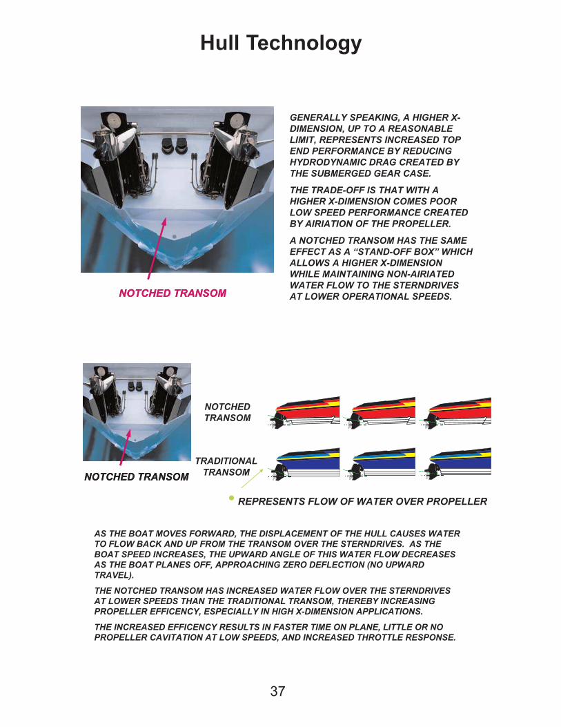
� REPRESENTS FLOW OF WATER OVER PROPELLER
37
Hull Technology
NOTCHED TRANSOMNOTCHED TRANSOM
GENERALLY SPEAKING, A HIGHER X-
DIMENSION, UP TO A REASONABLE
LIMIT, REPRESENTS INCREASED TOP
END PERFORMANCE BY REDUCING
HYDRODYNAMIC DRAG CREATED BY
THE SUBMERGED GEAR CASE.
THE TRADE-OFF IS THAT WITH A
HIGHER X-DIMENSION COMES POOR
LOW SPEED PERFORMANCE CREATED
BY AIRIATION OF THE PROPELLER.
A NOTCHED TRANSOM HAS THE SAME
EFFECT AS A “STAND-OFF BOX” WHICH
ALLOWS A HIGHER X-DIMENSION
WHILE MAINTAINING NON-AIRIATED
WATER FLOW TO THE STERNDRIVES
AT LOWER OPERATIONAL SPEEDS.
AS THE BOAT MOVES FORWARD, THE DISPLACEMENT OF THE HULL CAUSES WATER
TO FLOW BACK AND UP FROM THE TRANSOM OVER THE STERNDRIVES. AS THE
BOAT SPEED INCREASES, THE UPWARD ANGLE OF THIS WATER FLOW DECREASES
AS THE BOAT PLANES OFF, APPROACHING ZERO DEFLECTION (NO UPWARD
TRAVEL).
THE NOTCHED TRANSOM HAS INCREASED WATER FLOW OVER THE STERNDRIVES
AT LOWER SPEEDS THAN THE TRADITIONAL TRANSOM, THEREBY INCREASING
PROPELLER EFFICENCY, ESPECIALLY IN HIGH X-DIMENSION APPLICATIONS.
THE INCREASED EFFICENCY RESULTS IN FASTER TIME ON PLANE, LITTLE OR NO
PROPELLER CAVITATION AT LOW SPEEDS, AND INCREASED THROTTLE RESPONSE.
NOTCHED TRANSOMNOTCHED TRANSOM
NOTCHED
TRANSOM
38
Hull Technology
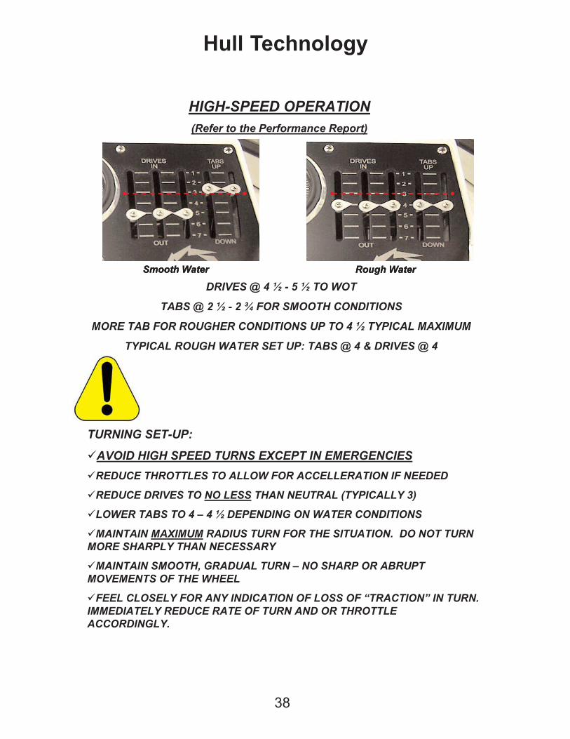
TURNING SET-UP:
AVOID HIGH SPEED TURNS EXCEPT IN EMERGENCIES
REDUCE THROTTLES TO ALLOW FOR ACCELLERATION IF NEEDED
REDUCE DRIVES TO NO LESS THAN NEUTRAL (TYPICALLY 3)
LOWER TABS TO 4 – 4 ½ DEPENDING ON WATER CONDITIONS
MAINTAIN MAXIMUM RADIUS TURN FOR THE SITUATION. DO NOT TURN
MORE SHARPLY THAN NECESSARY
MAINTAIN SMOOTH, GRADUAL TURN – NO SHARP OR ABRUPT
MOVEMENTS OF THE WHEEL
FEEL CLOSELY FOR ANY INDICATION OF LOSS OF “TRACTION” IN TURN.
IMMEDIATELY REDUCE RATE OF TURN AND OR THROTTLE
ACCORDINGLY.
HIGH-SPEED OPERATION
(Refer to the Performance Report)
DRIVES @ 4 ½ - 5 ½ TO WOT
TABS @ 2 ½ - 2 ¾ FOR SMOOTH CONDITIONS
MORE TAB FOR ROUGHER CONDITIONS UP TO 4 ½ TYPICAL MAXIMUM
TYPICAL ROUGH WATER SET UP: TABS @ 4 & DRIVES @ 4
Smooth WaterSmooth WaterSmooth Water Rough WaterRough WaterRough Water
39
Hull Technology
Thrust Angle
CG
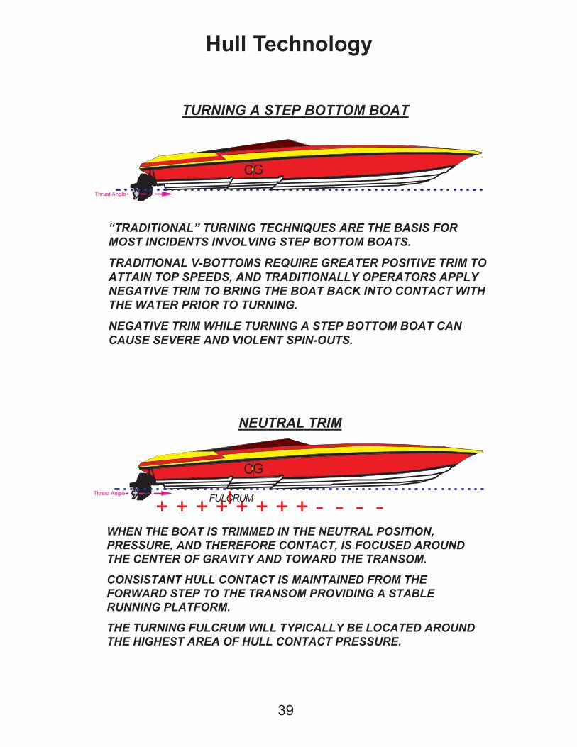
TURNING A STEP BOTTOM BOAT
“TRADITIONAL” TURNING TECHNIQUES ARE THE BASIS FOR
MOST INCIDENTS INVOLVING STEP BOTTOM BOATS.
TRADITIONAL V-BOTTOMS REQUIRE GREATER POSITIVE TRIM TO
ATTAIN TOP SPEEDS, AND TRADITIONALLY OPERATORS APPLY
NEGATIVE TRIM TO BRING THE BOAT BACK INTO CONTACT WITH
THE WATER PRIOR TO TURNING.
NEGATIVE TRIM WHILE TURNING A STEP BOTTOM BOAT CAN
CAUSE SEVERE AND VIOLENT SPIN-OUTS.
NEUTRAL TRIM
WHEN THE BOAT IS TRIMMED IN THE NEUTRAL POSITION,
PRESSURE, AND THEREFORE CONTACT, IS FOCUSED AROUND
THE CENTER OF GRAVITY AND TOWARD THE TRANSOM.
CONSISTANT HULL CONTACT IS MAINTAINED FROM THE
FORWARD STEP TO THE TRANSOM PROVIDING A STABLE
RUNNING PLATFORM.
THE TURNING FULCRUM WILL TYPICALLY BE LOCATED AROUND
THE HIGHEST AREA OF HULL CONTACT PRESSURE.
Thrust Angle
CG
+ ---++++++ + -FULCRUM
40
Hull Technology
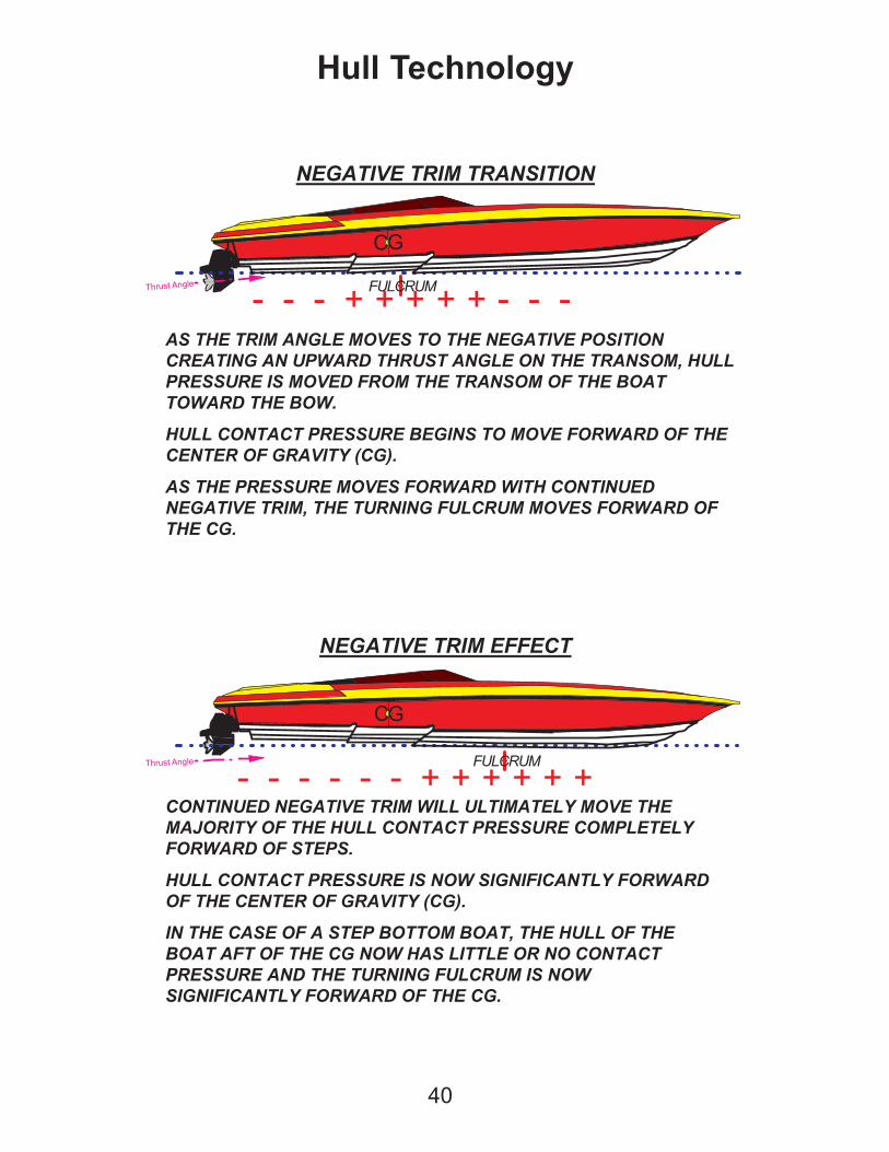
NEGATIVE TRIM TRANSITION
AS THE TRIM ANGLE MOVES TO THE NEGATIVE POSITION
CREATING AN UPWARD THRUST ANGLE ON THE TRANSOM, HULL
PRESSURE IS MOVED FROM THE TRANSOM OF THE BOAT
TOWARD THE BOW.
HULL CONTACT PRESSURE BEGINS TO MOVE FORWARD OF THE
CENTER OF GRAVITY (CG).
AS THE PRESSURE MOVES FORWARD WITH CONTINUED
NEGATIVE TRIM, THE TURNING FULCRUM MOVES FORWARD OF
THE CG.
Thrust Angle
CG
+ + + + +- - - - - -FULCRUM
NEGATIVE TRIM EFFECT
CONTINUED NEGATIVE TRIM WILL ULTIMATELY MOVE THE
MAJORITY OF THE HULL CONTACT PRESSURE COMPLETELY
FORWARD OF STEPS.
HULL CONTACT PRESSURE IS NOW SIGNIFICANTLY FORWARD
OF THE CENTER OF GRAVITY (CG).
IN THE CASE OF A STEP BOTTOM BOAT, THE HULL OF THE
BOAT AFT OF THE CG NOW HAS LITTLE OR NO CONTACT
PRESSURE AND THE TURNING FULCRUM IS NOW
SIGNIFICANTLY FORWARD OF THE CG.
Thrust Angle
+ + + + + +- - - - - -
CG
FULCRUM
41
Hull Technology
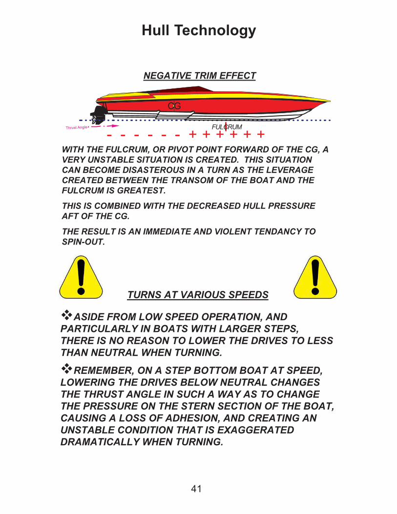
NEGATIVE TRIM EFFECT
Thrust Angle
+ + + + + +- - - - - -
CG
FULCRUM
TURNS AT VARIOUS SPEEDS
ASIDE FROM LOW SPEED OPERATION, AND
PARTICULARLY IN BOATS WITH LARGER STEPS,
THERE IS NO REASON TO LOWER THE DRIVES TO LESS
THAN NEUTRAL WHEN TURNING.
REMEMBER, ON A STEP BOTTOM BOAT AT SPEED,
LOWERING THE DRIVES BELOW NEUTRAL CHANGES
THE THRUST ANGLE IN SUCH A WAY AS TO CHANGE
THE PRESSURE ON THE STERN SECTION OF THE BOAT,
CAUSING A LOSS OF ADHESION, AND CREATING AN
UNSTABLE CONDITION THAT IS EXAGGERATED
DRAMATICALLY WHEN TURNING.
WITH THE FULCRUM, OR PIVOT POINT FORWARD OF THE CG, A
VERY UNSTABLE SITUATION IS CREATED. THIS SITUATION
CAN BECOME DISASTEROUS IN A TURN AS THE LEVERAGE
CREATED BETWEEN THE TRANSOM OF THE BOAT AND THE
FULCRUM IS GREATEST.
THIS IS COMBINED WITH THE DECREASED HULL PRESSURE
AFT OF THE CG.
THE RESULT IS AN IMMEDIATE AND VIOLENT TENDANCY TO
SPIN-OUT.
42
Hull Technology
TRIM TO MAINTAIN DIRECT LINE OF THRUST (NEUTRAL
AS MINIMUM SETTING).
MAINTAIN CONTINUOUS HORIZON POSITIONING. IF YOU
LOOSE THE HORIZON, YOU ARE LIKELY TRIMMED TOO
HIGH.
USE COMMON SENSE & DISCRETION.
NEVER MAKE ABRUPT MANEUVERS OR TRIM CHANGES.
FEEL CLOSELY FOR ANY INDICATION OF LOSS OF
“TRACTION” IN A TURN. IMMEDIATELY REDUCE RATE OF
TURN AND/OR THROTTLE ACCORDINGLY.
DRIVE WITHIN YOUR ABILITIES, AND WITHIN SAFETY
PARAMETERS.
SUMMARY
Leave engine hatch door open before you begin starting procedures.
Familiarize yourself with the dashboard, side panel, gauges, switches
and controls.
Turn on your battery switches to the desired
positions. (Port, (Center), Starboard, 1-2 or All)
Battery Switches are located under the cockpit
sink unit. (“Both” & “Parallel” link all of the batter-
ies in Parallel. This will utilize all of the batteries
for engine starting; however, a single “bad” bat-
tery could cause the others to drain.)
On gasoline powered boats, locate blower toggle switch on left hand
side of dashboard, above the throttle/shifter quadrant. Flip on blower
switch, red indicator light will illuminate. (Blowers are running) Run
blowers for at least five (5) minutes before starting engines. Diesel
powered boats may or may not have engine compartment blowers.
Note: Blowers should be run until vessel is under way.
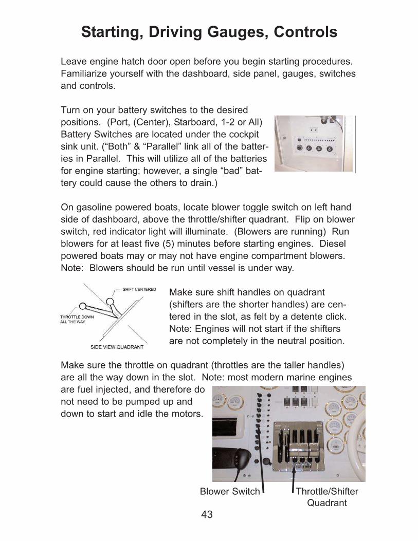
Make sure shift handles on quadrant
(shifters are the shorter handles) are cen-
tered in the slot, as felt by a detente click.
Note: Engines will not start if the shifters
are not completely in the neutral position.
Make sure the throttle on quadrant (throttles are the taller handles)
are all the way down in the slot. Note: most modern marine engines
are fuel injected, and therefore do
not need to be pumped up and
down to start and idle the motors.
43
Starting, Driving Gauges, Controls
Blower Switch Throttle/Shifter
Quadrant
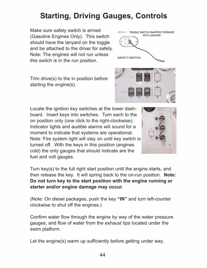
Make sure safety switch is armed
(Gasoline Engines Only). This switch
should have the lanyard on the toggle
and be attached to the driver for safety.
Note: The engines will not run unless
this switch is in the run position.
Trim drive(s) to the in position before
starting the engine(s).
Locate the ignition key switches at the lower dash-
board. Insert keys into switches. Turn each to the
on position only (one click to the right-clockwise).
Indicator lights and audible alarms will sound for a
moment to indicate that systems are operational.
Note: Fire system light will stay on until key switch is
turned off. With the keys in this position (engines
cold) the only gauges that should indicate are the
fuel and volt gauges.
Turn key(s) to the full right start position until the engine starts, and
then release the key. It will spring back to the on-run position. Note:
Do not turn key to the start position with the engine running or
starter and/or engine damage may occur.
(Note: On diesel packages, push the key “IN” and turn left-counter
clockwise to shut off the engines.)
Confirm water flow through the engine by way of the water pressure
gauges, and flow of water from the exhaust tips located under the
swim platform.
Let the engine(s) warm up sufficiently before getting under way.
44
Starting, Driving Gauges, Controls
Check your bilge and engine compartment once more for any leaks
or unusual noise. Engine hatch may now be closed.
While at the dock, raise throttle slightly for throttle response. Bring
throttle back to idle and check shifters for forward and reverse opera-
tion.
Check operation of equipment for trip (VHF, GPS, Depth Gauge,
Horns, etc.) Inform passengers of location of all safety equipment,
seating and grab rails.
Untie dock lines and stow them away. Push vessel away from dock,
or utilize the bow thruster to push away (if so equipped), and shift
into desired gear. (The bow thruster is described in the “Electrical
System & Optional Equipment” section.)
Pilot (helm) bolster and passenger bolster have rocker switch activat-
ed drop out seat bottoms for stand-up or sit-down operation. Adjust
these as necessary for a comfortable position.
Warning: With the vessel in motion, pay close attention to
heading and water depth. Use caution in shallow water
operation.
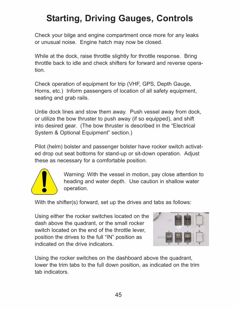
With the shifter(s) forward, set up the drives and tabs as follows:
Using either the rocker switches located on the
dash above the quadrant, or the small rocker
switch located on the end of the throttle lever,
position the drives to the full “IN” position as
indicated on the drive indicators.
Using the rocker switches on the dashboard above the quadrant,
lower the trim tabs to the full down position, as indicated on the trim
tab indicators.
45
Starting, Driving Gauges, Controls
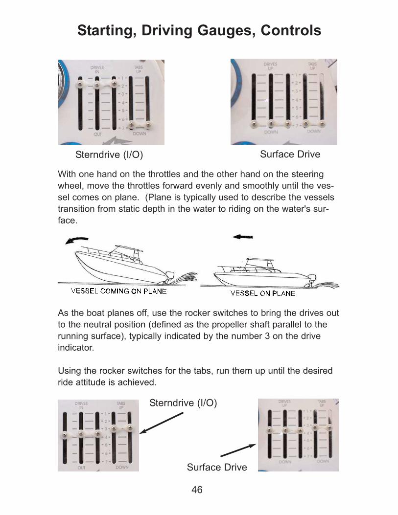
With one hand on the throttles and the other hand on the steering
wheel, move the throttles forward evenly and smoothly until the ves-
sel comes on plane. (Plane is typically used to describe the vessels
transition from static depth in the water to riding on the water's sur-
face.
As the boat planes off, use the rocker switches to bring the drives out
to the neutral position (defined as the propeller shaft parallel to the
running surface), typically indicated by the number 3 on the drive
indicator.
Using the rocker switches for the tabs, run them up until the desired
ride attitude is achieved.
46
Starting, Driving Gauges, Controls
Sterndrive (I/O) Surface Drive
Sterndrive (I/O)
Surface Drive
Warning: Never run the vessel at higher speeds with
the tabs or drives at the extreme in/out - up/down posi-
tions. Never trim the drives to less than 3 on the drive
trim indicator while the boat is on plane.
You will learn to adjust your vessel for a comfortable ride attitude
depending upon loading and balance to achieve desired perform-
ance. Take note of your indicator positions to aid in your running set-
up.
Always monitor your gauges, warning lights and audible warning
alarms. Back off of the throttles, bring the boat to a complete stop,
put the shifters in the neutral position, and shut down the engine(s) at
the sign of any problem. Check the engine compartment for possible
repair. Note: Vessel can be run back to port on one engine if neces-
sary (in a multi-engine configuration boat), as long as you do not
overwork the running engine. Call for help or tow-in if necessary.
While under way, it is necessary to frequently check the instrumenta-
tion for any possible sign of trouble.
Instrumentation:
Tachometer - The tachometer indicates the engine's revolutions per
minute (RPM). Use the tachometer to monitor engine speed to avoid
exceeding the maximum RPM rating for your engine.
Temperature Gauge - The temperature gauge indicates the engine
coolant temperature. If the gauge reads in the danger area, shut off
the engine, locate and repair the problem.
Oil Pressure Gauge - The oil pressure gauge indicates the engine
oil pressure. If the gauge reads low shut off the engine and repair
the problem before re-starting the engine.
Fuel Gauge - The fuel gauge indicates the approximate fuel level. At
times your gauge may provide an inaccurate reading because of the
water conditions and the level of the boat in the water. It is a good
idea to keep track of the fuel you have dispensed in the tank, running
47
Starting, Driving Gauges, Controls
time and fuel usage estimates to ensure you have an adequate fuel
supply for your trip.
Compass - The compass your boat is equipped with is an excellent
aid in navigation. Several factors can influence the operation of your
compass, such as the needle deflection caused by metal compo-
nents or the use of electrical equipment on your boat.
Keep a log on engine hours for timely service and maintenance to
keep your Fountain running strong, and to prevent possible prema-
ture equipment failure. Refer to engine and accessory manufactur-
ers manuals for service intervals. You engine hour meter is located
in the engine compartment on the starboard gunwale lip.
48
Starting, Driving Gauges, Controls
Electrical System:
Your Fountain Powerboat is equipped with standard 12VDC power.
All vessel power is operated by battery switch(s). Lights and acces-
sories are protected by fuses or breakers. These are located under
the rear seat or under the dashboard wall. Note: See trouble-shoot-
ing section for fuse replacement or breaker reset procedures.
Do not use 12 volt power accessories for long periods
of time without engines or generator running to insure
that batteries will not run down
Stereo, VHF and GPS, whether standard or optional upgrades should
include manuals provided by the original equipment manufacturer.
Please refer to these manuals for proper usage and maintenance of
these electronics.
VHF and GPS options are very useful and are recommended for
easy navigation and trip plotting. VHF radio is the communication
used by marine and aircraft, and is very useful for emergency, ship to
ship, or ship to shore communications.
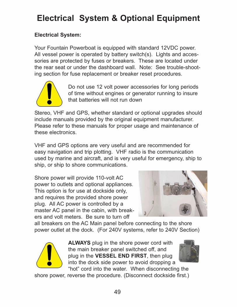
Shore power will provide 110-volt AC
power to outlets and optional appliances.
This option is for use at dockside only,
and requires the provided shore power
plug. All AC power is controlled by a
master AC panel in the cabin, with break-
ers and volt meters. Be sure to turn off
all breakers on the AC Main panel before connecting to the shore
power outlet at the dock. (For 240V systems, refer to 240V Section)
ALWAYS plug in the shore power cord with
the main breaker panel switched off, and
plug in the VESSEL END FIRST, then plug
into the dock side power to avoid dropping a
“hot” cord into the water. When disconnecting the
shore power, reverse the procedure. (Disconnect dockside first.)
49
Electrical System & Optional Equipment

On the AC panel, slide the cover up exposing the shore power break-
er, and turn on the breaker to utilize shore power.
A safety cover is provided over the switches
that direct power to the panel to prevent both
shore power and generator power from being
used simultaneously. For shore power opera-
tion, plug the outlet into the boat receptacle
then plug into the dockside shore power out-
let. On the boat AC panel, slide the cover
down exposing the shore power breaker, and
turn on the breaker to utilize shore power.
Generator Operation:
All Fountain cruisers are typically equipped with an AC generator.
This will provide 110-volt AC power to outlets and optional appliances
while away from the dock, or in locations that do not have dock-side
power available. Power is controlled by a master AC panel in the
cabin, with breakers and volt meters. It is important to understand
the operation of this system when switching from shore power to
generator power.
Before use, always make certain that
water control valves to the generator
are open, and the sea strainers are
clean, or severe damage may occur to
your generator. Always confirm water
flow from the generator by
visually checking for water
flow from the generator exhaust vent. If
water is not flowing from the exhaust, shut off
the generator immediately.
Read and familiarize yourself with the owner's manual provided by
your generator manufacturer for more specific details of operation.
Turn the generator battery switch on. The generator batteryswitch is located in the wet bar cabinet in the cockpit.
50
Electrical System & Optional Equipment
Generator/Shore Power Select
The generator can be started (2) ways-either in the engine com-partment or on the main panel in the salon.
It may be necessary (depending on the model of your generator)to hold the "Pre-Heat" button, (particularly in diesel applications),
while starting the generator. Refer to the manufacturer owner's man-
ual for specific details.
Once the generator has started, flip the main breaker on thegenerator face to the on position, (if so equipped).
Note: The generator will shut itself down at sign of trouble, including
overheat, low oil, etc. The generator has it’s own battery and on-off
switch. There is also a cross-over switch to utilize engine batteries for
start-up.
On the AC panel, slide the cover up exposing the generator breaker,
and turn on the breaker to utilize generator power.
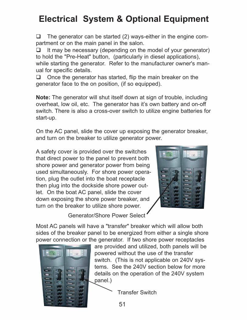
A safety cover is provided over the switches
that direct power to the panel to prevent both
shore power and generator power from being
used simultaneously. For shore power opera-
tion, plug the outlet into the boat receptacle
then plug into the dockside shore power out-
let. On the boat AC panel, slide the cover
down exposing the shore power breaker, and
turn on the breaker to utilize shore power.
Most AC panels will have a "transfer" breaker which will allow both
sides of the breaker panel to be energized from either a single shore
power connection or the generator. If two shore power receptacles
are provided and utilized, both panels will be
powered without the use of the transfer
switch. (This is not applicable on 240V sys-
tems. See the 240V section below for more
details on the operation of the 240V system
panel.)
51
Electrical System & Optional Equipment
Transfer Switch
Generator/Shore Power Select
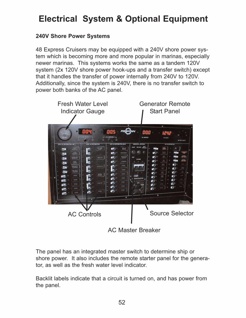
240V Shore Power Systems
48 Express Cruisers may be equipped with a 240V shore power sys-
tem which is becoming more and more popular in marinas, especially
newer marinas. This systems works the same as a tandem 120V
system (2x 120V shore power hook-ups and a transfer switch) except
that it handles the transfer of power internally from 240V to 120V.
Additionally, since the system is 240V, there is no transfer switch to
power both banks of the AC panel.
The panel has an integrated master switch to determine ship or
shore power. It also includes the remote starter panel for the genera-
tor, as well as the fresh water level indicator.
Backlit labels indicate that a circuit is turned on, and has power from
the panel.
52
Electrical System & Optional Equipment
AC Controls Source Selector
AC Master Breaker
Generator Remote
Start Panel
Fresh Water Level
Indicator Gauge
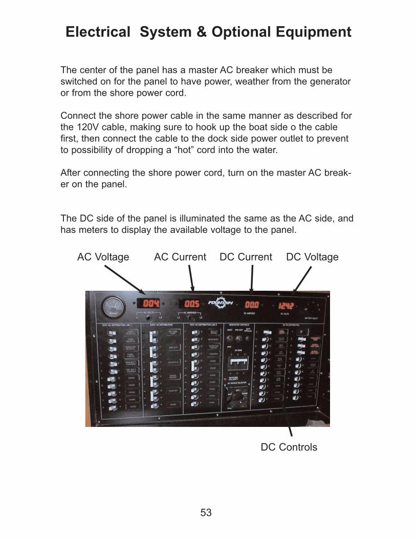
The center of the panel has a master AC breaker which must be
switched on for the panel to have power, weather from the generator
or from the shore power cord.
Connect the shore power cable in the same manner as described for
the 120V cable, making sure to hook up the boat side o the cable
first, then connect the cable to the dock side power outlet to prevent
to possibility of dropping a “hot” cord into the water.
After connecting the shore power cord, turn on the master AC break-
er on the panel.
The DC side of the panel is illuminated the same as the AC side, and
has meters to display the available voltage to the panel.
53
Electrical System & Optional Equipment
DC Controls
AC Voltage DC VoltageAC Current DC Current
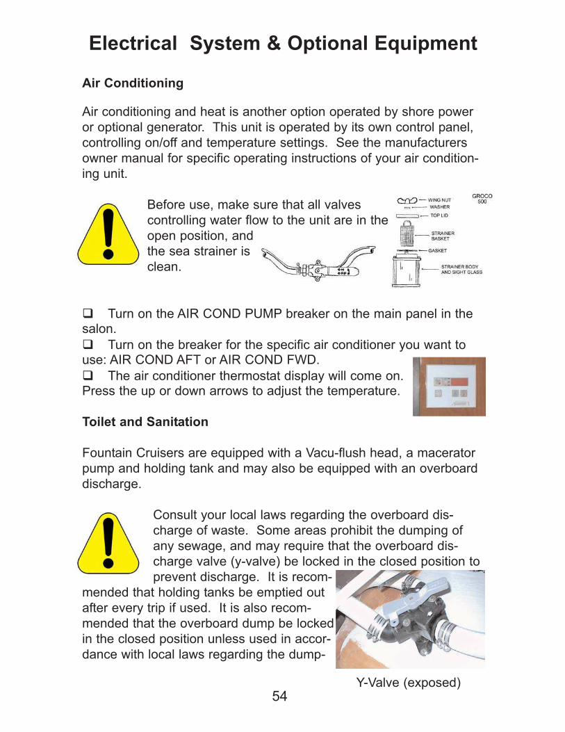
Air Conditioning
Air conditioning and heat is another option operated by shore power
or optional generator. This unit is operated by its own control panel,
controlling on/off and temperature settings. See the manufacturers
owner manual for specific operating instructions of your air condition-
ing unit.
Before use, make sure that all valves
controlling water flow to the unit are in the
open position, and
the sea strainer is
clean.
Turn on the AIR COND PUMP breaker on the main panel in thesalon.
Turn on the breaker for the specific air conditioner you want touse: AIR COND AFT or AIR COND FWD.
The air conditioner thermostat display will come on.Press the up or down arrows to adjust the temperature.
Toilet and Sanitation
Fountain Cruisers are equipped with a Vacu-flush head, a macerator
pump and holding tank and may also be equipped with an overboard
discharge.
Consult your local laws regarding the overboard dis-
charge of waste. Some areas prohibit the dumping of
any sewage, and may require that the overboard dis-
charge valve (y-valve) be locked in the closed position to
prevent discharge. It is recom-
mended that holding tanks be emptied out
after every trip if used. It is also recom-
mended that the overboard dump be locked
in the closed position unless used in accor-
dance with local laws regarding the dump-
54
Electrical System & Optional Equipment
Y-Valve (exposed)
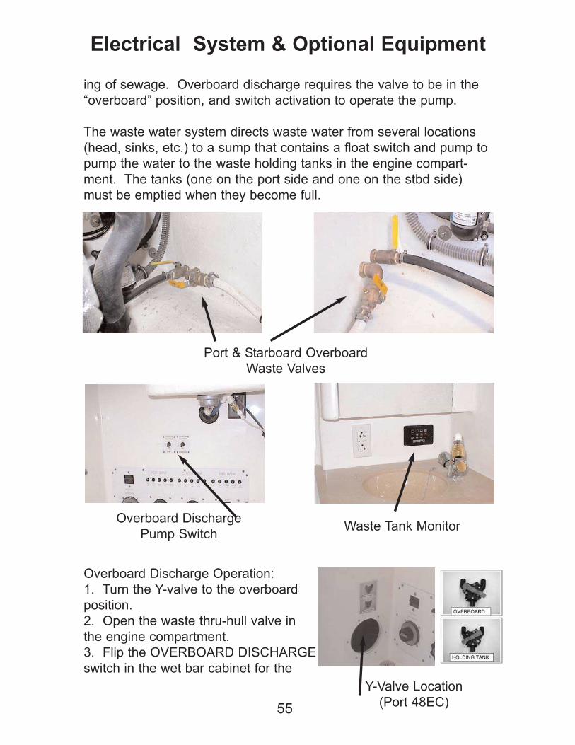
ing of sewage. Overboard discharge requires the valve to be in the
“overboard” position, and switch activation to operate the pump.
The waste water system directs waste water from several locations
(head, sinks, etc.) to a sump that contains a float switch and pump to
pump the water to the waste holding tanks in the engine compart-
ment. The tanks (one on the port side and one on the stbd side)
must be emptied when they become full.
Overboard Discharge Operation:
1. Turn the Y-valve to the overboard
position.
2. Open the waste thru-hull valve in
the engine compartment.
3. Flip the OVERBOARD DISCHARGE
switch in the wet bar cabinet for the
55
Electrical System & Optional Equipment
Port & Starboard Overboard
Waste Valves
Overboard Discharge
Pump SwitchWaste Tank Monitor
Y-Valve Location
(Port 48EC)
corresponding tank you want to empty.
4. When the tank is empty, release the OVERBOARD DIS-
CHARGE switch. Turn the Y-valve to the original position and close
the waste thru-hull.
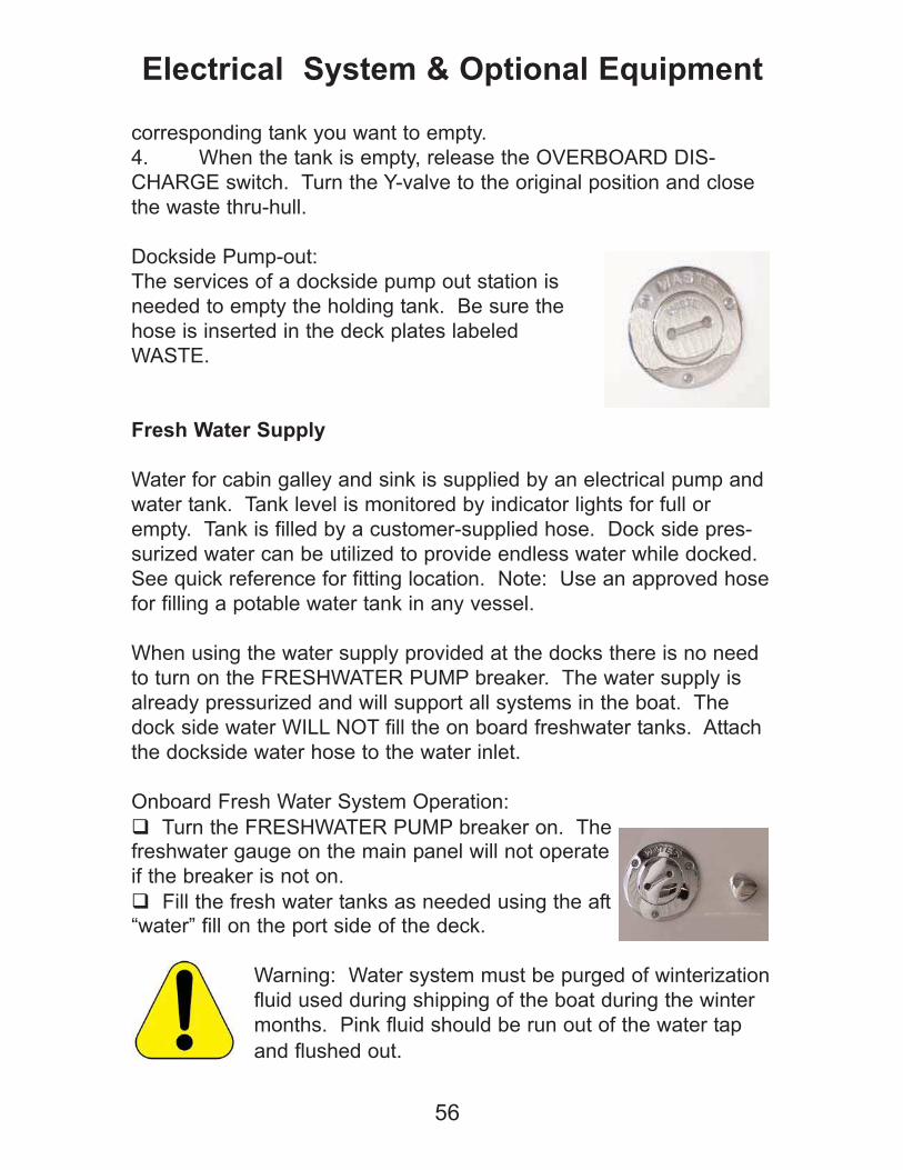
Dockside Pump-out:
The services of a dockside pump out station is
needed to empty the holding tank. Be sure the
hose is inserted in the deck plates labeled
WASTE.
Fresh Water Supply
Water for cabin galley and sink is supplied by an electrical pump and
water tank. Tank level is monitored by indicator lights for full or
empty. Tank is filled by a customer-supplied hose. Dock side pres-
surized water can be utilized to provide endless water while docked.
See quick reference for fitting location. Note: Use an approved hose
for filling a potable water tank in any vessel.
When using the water supply provided at the docks there is no need
to turn on the FRESHWATER PUMP breaker. The water supply is
already pressurized and will support all systems in the boat. The
dock side water WILL NOT fill the on board freshwater tanks. Attach
the dockside water hose to the water inlet.
Onboard Fresh Water System Operation:
Turn the FRESHWATER PUMP breaker on. Thefreshwater gauge on the main panel will not operate
if the breaker is not on.
Fill the fresh water tanks as needed using the aft“water” fill on the port side of the deck.
Warning: Water system must be purged of winterization
fluid used during shipping of the boat during the winter
months. Pink fluid should be run out of the water tap
and flushed out.
56
Electrical System & Optional Equipment
Engine Optional Equipment
Silent Choice Exhaust: This option allows vessel pilot to choose
straight out exhaust or quieter operation at the flip of a switch. This
is located at the pilot's right side helm switch panel, labeled "Exhaust
Open or Closed". Note: This system may not be legal for operation
in certain areas. It is the responsibility of the vessel owner to know
and understand the local noise laws, and outfit the vessel according-
ly. It is strongly recommended that the vessel operator use common
sense and courtesy when operating the boat in marinas, around
homes, and in areas that excessive noise would be inconsiderate
and/or inappropriate.
Warning: Some waterway areas have noise level laws
that are very strictly enforced. Check with the local laws
in your area prior to operating your boat.
It is also recommended by many engine manufacturers to not use a
switchable exhaust system at higher speeds due to potential engine
damage that may occur.
Engine fresh water flush:
This option allows you to flush out your engine of saltwater and silt
after a trip. This system can be used at dockside, trailer or on a
hoist. It is also used to run the engine(s) while the boat is out of the
water for diagnostic and troubleshooting service. Use this step-by-
step procedure as follows:
Engine flush valves are located inside the engine compartment on
the inner transom above each of the engine drive gimbals. The gar-
den hose fitting for the flush system is located on the engine com-
partment lip.
Note: Diesel powered boats are flushed at the sea strainers, and do
not have separate flushing valves or water inlets on the deck.
57
Electrical System & Optional Equipment
Make sure that the boat attitude is NOT bow down. Raise the bow of
the boat to get the engine exhaust tips to angle downward so as to
insure that flush water does not flow back into the exhaust pipes, and
thus into the engine. Severe engine damage will occur is water is
ingested by the engine(s) through the exhaust pipes.
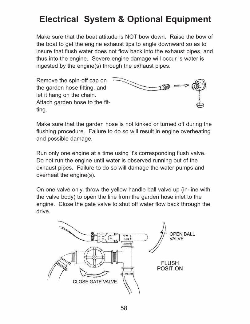
Remove the spin-off cap on
the garden hose fitting, and
let it hang on the chain.
Attach garden hose to the fit-
ting.
Make sure that the garden hose is not kinked or turned off during the
flushing procedure. Failure to do so will result in engine overheating
and possible damage.
Run only one engine at a time using it's corresponding flush valve.
Do not run the engine until water is observed running out of the
exhaust pipes. Failure to do so will damage the water pumps and
overheat the engine(s).
On one valve only, throw the yellow handle ball valve up (in-line with
the valve body) to open the line from the garden hose inlet to the
engine. Close the gate valve to shut off water flow back through the
drive.
58
Electrical System & Optional Equipment
Turn on the garden hose all the way, and wait for water to come out
of the exhaust pipes.
Start the engine corresponding to the valve you just set up to flush,
and run the engine (at idle) the desired time to flush out the engine.
Continually monitor the engine gauges while flushing to verify engine
temperature.
When finished flushing, shut down the engine first, and then turn off
the garden hose. Return the engine flush valve to the run position
(turn the ball valve to the off position, perpendicular to the valve
body, open the gate valve by turning counterclockwise).
Repeat the procedure for each engine.
Make sure that you return the flush valve to the run
position as described above. Failure to do so will result
in damage to the water pump, and may cause severe
engine damage.
Remove the garden hose from the fitting, and re-cap the fitting.
Battery Charger:
A battery charger is used with shore power while docked, on the
trailer, or on your hoist. This unit will keep your batteries charged
and monitored while the vessel is shut down for a period of time.
This unit is located inside the mechanical access or in the engine
compartment of inboard powered boats. Refer to the quick reference
drawings for the location of the charger. The battery charger has
indicator lights to show low or full charge.
With the boat attached to shore power, or with the generator running,
turn on the BATTERY CHARGER breaker on the main AC/DC panel.
59
Electrical System & Optional Equipment
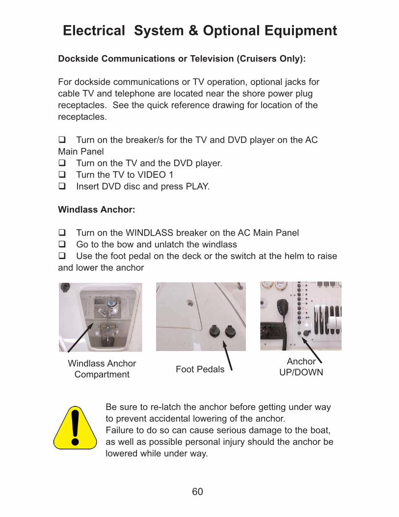
Dockside Communications or Television (Cruisers Only):
For dockside communications or TV operation, optional jacks for
cable TV and telephone are located near the shore power plug
receptacles. See the quick reference drawing for location of the
receptacles.
Turn on the breaker/s for the TV and DVD player on the AC
Main Panel
Turn on the TV and the DVD player.
Turn the TV to VIDEO 1
Insert DVD disc and press PLAY.
Windlass Anchor:
Turn on the WINDLASS breaker on the AC Main Panel
Go to the bow and unlatch the windlass
Use the foot pedal on the deck or the switch at the helm to raise
and lower the anchor
Be sure to re-latch the anchor before getting under way
to prevent accidental lowering of the anchor.
Failure to do so can cause serious damage to the boat,
as well as possible personal injury should the anchor be
lowered while under way.
60
Electrical System & Optional Equipment
Windlass Anchor
CompartmentFoot Pedals
Anchor
UP/DOWN
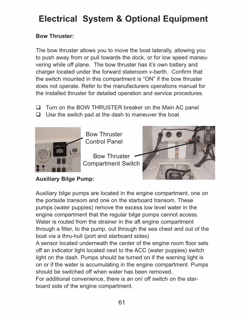
Bow Thruster:
The bow thruster allows you to move the boat laterally, allowing you
to push away from or pull towards the dock, or for low speed maneu-
vering while off plane. The bow thruster has it’s own battery and
charger located under the forward stateroom v-berth. Confirm that
the switch mounted in this compartment is “ON” if the bow thruster
does not operate. Refer to the manufacturers operations manual for
the installed thruster for detailed operation and service procedures.
Turn on the BOW THRUSTER breaker on the Main AC panel
Use the switch pad at the dash to maneuver the boat
Auxiliary Bilge Pump:
Auxiliary bilge pumps are located in the engine compartment, one on
the portside transom and one on the starboard transom. These
pumps (water puppies) remove the excess low level water in the
engine compartment that the regular bilge pumps cannot access.
Water is routed from the strainer in the aft engine compartment
through a filter, to the pump, out through the sea chest and out of the
boat via a thru-hull (port and starboard sides)
A sensor located underneath the center of the engine room floor sets
off an indicator light located next to the ACC (water puppies) switch
light on the dash. Pumps should be turned on if the warning light is
on or if the water is accumulating in the engine compartment. Pumps
should be switched off when water has been removed.
For additional convenience, there is an on/ off switch on the star-
board side of the engine compartment.
61
Electrical System & Optional Equipment
Bow Thruster
Control Panel
Bow Thruster
Compartment Switch
Exterior:
Hull, Deck Fittings and Windshield. Hull and deck surfaces are
gel coat and polyurethane painted graphics.
Warning: Do not use any harsh detergents or solvents
on gel coat or painted surfaces.
Wash hull and deck with boat soap. Rinse well with water, and
towel dry. (Soft terry cloth or chamois).
Protect hull and deck with top grade fiberglass wax. Use fiber-
glass polish for faded or scratched surfaces, the re-wax.
Use a gel coat repair kit for any chips or gouges. Finish, polish
and re-wax.
Stainless fittings can be wiped clean. Hand rub metal polish and
wax.
Powder coated fittings: Use mild hand rub polish and
wax.
Windshield: Wash with mild soap and water. Do not
use Windex, chemicals, or any abrasives.
Cabin and Fixtures: Cabins are not unlike household cleaning
Vacuum carpet and shampoo when needed. Spot removers and
freshener will keep the carpet clean and fresh.
Upholstery: Use a good quality vinyl cleaner and conditioner.
62
Appearance and Care

Counter tops, sinks, glass, etc.: Use household cleaning products
to keep these items clean.
Do not run garden hose in cabin.
Do not use harsh chemicals, solvents or abrasives.
Do not spray water or cleaners in master electrical panel.
Cockpit, Upholstery, Dashboard:
Cockpit has removable carpet. This can be vacuumed and
shampooed as needed.
Upholstery: Use a good vinyl cleaner and conditioner.
Under the cockpit removable carpet is a non-skid gel coat fiber-
glass floor. This can be cleaned with a scrub brush using soap
and water, then rinse well.
Dashboard: Wipe well with a damp cloth and dry with a terry
towel.
Do not flood dash with hose water. (Light spray is ok.)
Do not use chemicals or abrasives on the dashboard. Gauge
lenses could become scratched or clouded.
Engine(s) and Engine Compartment:
With drain plugs removed, tilt boat with the bow as high as possi-
ble. Hose out bilge with soap and water. For greasy areas, use
a marine bilge degreaser. Rinse with fresh water. Note: If
stringer sections fill up with water, clear drain plug fittings and
drain holes with a stick or rod.
Lightly rinse engine components, generator housing and acces-
63
Appearance and Care
sories, pat dry and coat with a protectant such as CRC or WD-
40. Do not flood engines, or other components in the engine
compartment with water.
Be aware of local laws regarding discharge of oily or greasy
water from the bilge while cleaning. It is unlawful to discharge oil
into the water per federal law.
Polish stainless pipes and metals with stainless steel polish and
rags.
64
Appearance and Care
We do not recommend storing the boat in the water on a mooring
buoy, or tied to a dock. It is impossible to project situations that
could result in the boat becoming swamped, resulting in significant
damage, or total loss.
Store the boat with the cockpit cover on, and any provided poles
installed to prevent pooling of water on the cover.
When possible, cover the entire boat to protect from UV rays and the
elements.
Always store the boat in a "bow up" position. This way, any water
that may be in the boat, or find its way into the boat will move toward
the back and exit through the drain plugs.
Remove drain plugs when stored on the trailer.
We recommend the use of a dehumidifier in the cabin to prevent
moisture damage while storing the boat in moist climates.
Always winterize your boat for storage in freezing cli-
mates. Be sure to winterize all water systems, engines
and drives, and generator systems. Refer to a qualified
marine technician for this service. Freezing can cause
severe damage to marine engine components, water
systems and drive units.
It is recommended that you have your boat “bottom
painted” with an approved “anti-fouling” finish if you plan
to store it in the water for more that 48 hours at a time.
Extended submersion of painted surfaces can result in
blistering and other paint damage that is not covered
under warranty.
65
Storage
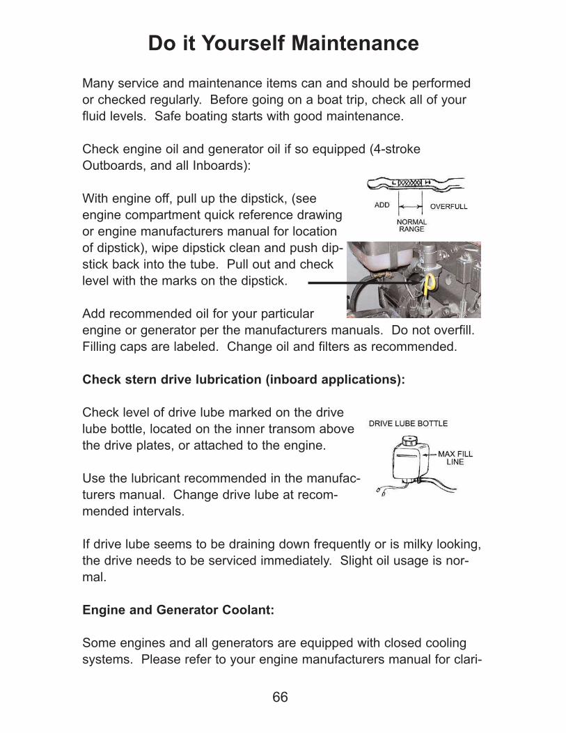
Many service and maintenance items can and should be performed
or checked regularly. Before going on a boat trip, check all of your
fluid levels. Safe boating starts with good maintenance.
Check engine oil and generator oil if so equipped (4-stroke
Outboards, and all Inboards):
With engine off, pull up the dipstick, (see
engine compartment quick reference drawing
or engine manufacturers manual for location
of dipstick), wipe dipstick clean and push dip-
stick back into the tube. Pull out and check
level with the marks on the dipstick.
Add recommended oil for your particular
engine or generator per the manufacturers manuals. Do not overfill.
Filling caps are labeled. Change oil and filters as recommended.
Check stern drive lubrication (inboard applications):
Check level of drive lube marked on the drive
lube bottle, located on the inner transom above
the drive plates, or attached to the engine.
Use the lubricant recommended in the manufac-
turers manual. Change drive lube at recom-
mended intervals.
If drive lube seems to be draining down frequently or is milky looking,
the drive needs to be serviced immediately. Slight oil usage is nor-
mal.
Engine and Generator Coolant:
Some engines and all generators are equipped with closed cooling
systems. Please refer to your engine manufacturers manual for clari-
66
Do it Yourself Maintenance
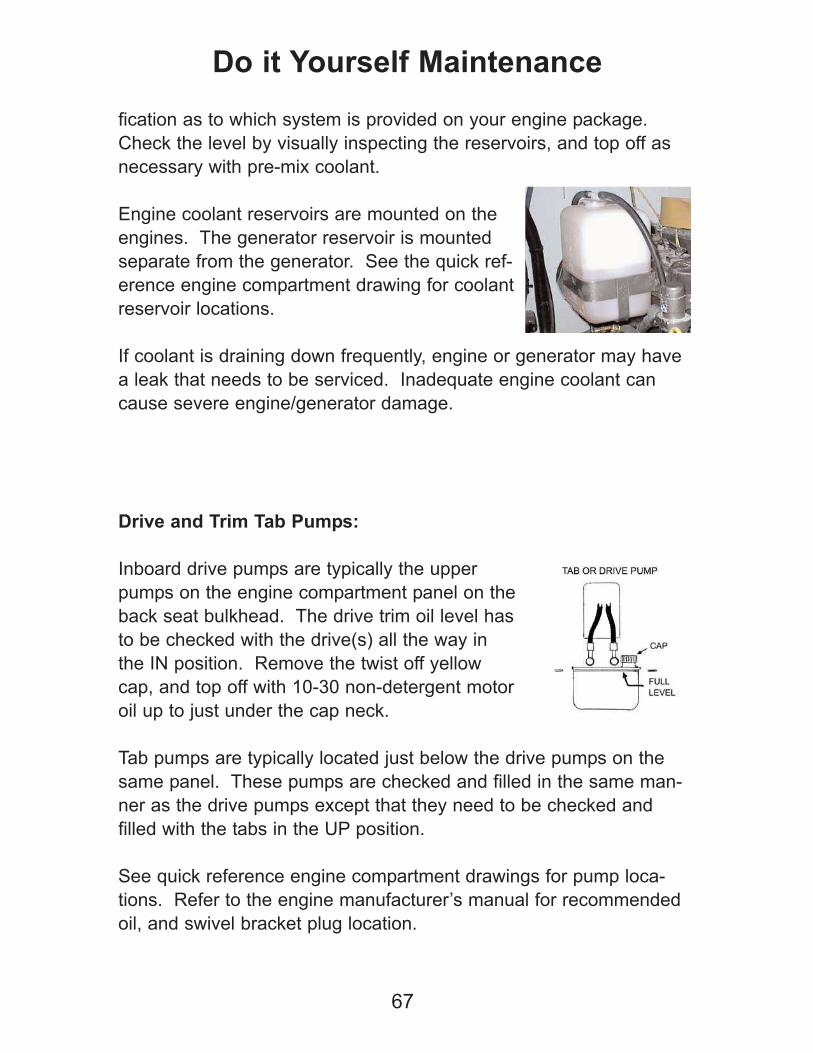
fication as to which system is provided on your engine package.
Check the level by visually inspecting the reservoirs, and top off as
necessary with pre-mix coolant.
Engine coolant reservoirs are mounted on the
engines. The generator reservoir is mounted
separate from the generator. See the quick ref-
erence engine compartment drawing for coolant
reservoir locations.
If coolant is draining down frequently, engine or generator may have
a leak that needs to be serviced. Inadequate engine coolant can
cause severe engine/generator damage.
Drive and Trim Tab Pumps:
Inboard drive pumps are typically the upper
pumps on the engine compartment panel on the
back seat bulkhead. The drive trim oil level has
to be checked with the drive(s) all the way in
the IN position. Remove the twist off yellow
cap, and top off with 10-30 non-detergent motor
oil up to just under the cap neck.
Tab pumps are typically located just below the drive pumps on the
same panel. These pumps are checked and filled in the same man-
ner as the drive pumps except that they need to be checked and
filled with the tabs in the UP position.
See quick reference engine compartment drawings for pump loca-
tions. Refer to the engine manufacturer’s manual for recommended
oil, and swivel bracket plug location.
67
Do it Yourself Maintenance
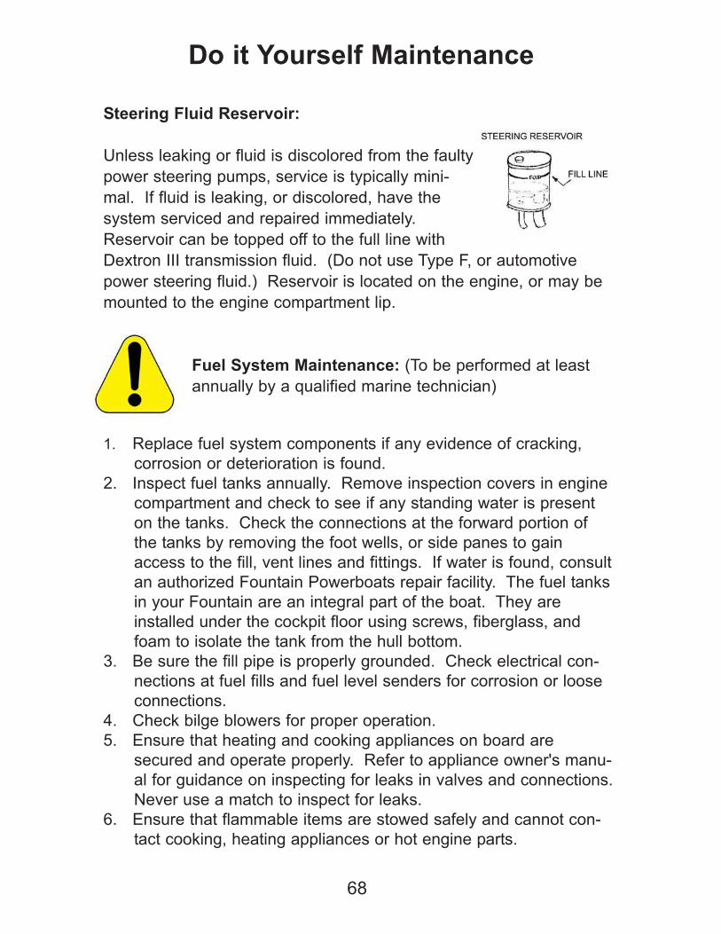
68
Do it Yourself Maintenance
Steering Fluid Reservoir:
Unless leaking or fluid is discolored from the faulty
power steering pumps, service is typically mini-
mal. If fluid is leaking, or discolored, have the
system serviced and repaired immediately.
Reservoir can be topped off to the full line with
Dextron III transmission fluid. (Do not use Type F, or automotive
power steering fluid.) Reservoir is located on the engine, or may be
mounted to the engine compartment lip.
Fuel System Maintenance: (To be performed at least
annually by a qualified marine technician)
1. Replace fuel system components if any evidence of cracking,
corrosion or deterioration is found.
2. Inspect fuel tanks annually. Remove inspection covers in engine
compartment and check to see if any standing water is present
on the tanks. Check the connections at the forward portion of
the tanks by removing the foot wells, or side panes to gain
access to the fill, vent lines and fittings. If water is found, consult
an authorized Fountain Powerboats repair facility. The fuel tanks
in your Fountain are an integral part of the boat. They are
installed under the cockpit floor using screws, fiberglass, and
foam to isolate the tank from the hull bottom.
3. Be sure the fill pipe is properly grounded. Check electrical con-
nections at fuel fills and fuel level senders for corrosion or loose
connections.
4. Check bilge blowers for proper operation.
5. Ensure that heating and cooking appliances on board are
secured and operate properly. Refer to appliance owner's manu-
al for guidance on inspecting for leaks in valves and connections.
Never use a match to inspect for leaks.
6. Ensure that flammable items are stowed safely and cannot con-
tact cooking, heating appliances or hot engine parts.
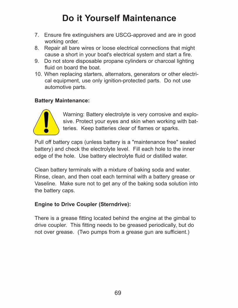
7. Ensure fire extinguishers are USCG-approved and are in good
working order.
8. Repair all bare wires or loose electrical connections that might
cause a short in your boat's electrical system and start a fire.
9. Do not store disposable propane cylinders or charcoal lighting
fluid on board the boat.
10. When replacing starters, alternators, generators or other electri-
cal equipment, use only ignition-protected parts. Do not use
automotive parts.
Battery Maintenance:
Warning: Battery electrolyte is very corrosive and explo-
sive. Protect your eyes and skin when working with bat-
teries. Keep batteries clear of flames or sparks.
Pull off battery caps (unless battery is a "maintenance free" sealed
battery) and check the electrolyte level. Fill each hole to the inner
edge of the hole. Use battery electrolyte fluid or distilled water.
Clean battery terminals with a mixture of baking soda and water.
Rinse, clean, and then coat each terminal with a battery grease or
Vaseline. Make sure not to get any of the baking soda solution into
the battery caps.
Engine to Drive Coupler (Sterndrive):
There is a grease fitting located behind the engine at the gimbal to
drive coupler. This fitting needs to be greased periodically, but do
not over grease. (Two pumps from a grease gun are sufficient.)
69
Do it Yourself Maintenance
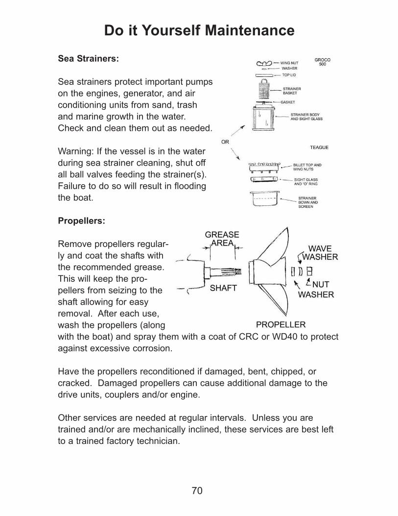
70
Sea Strainers:
Sea strainers protect important pumps
on the engines, generator, and air
conditioning units from sand, trash
and marine growth in the water.
Check and clean them out as needed.
Warning: If the vessel is in the water
during sea strainer cleaning, shut off
all ball valves feeding the strainer(s).
Failure to do so will result in flooding
the boat.
Propellers:
Remove propellers regular-
ly and coat the shafts with
the recommended grease.
This will keep the pro-
pellers from seizing to the
shaft allowing for easy
removal. After each use,
wash the propellers (along
with the boat) and spray them with a coat of CRC or WD40 to protect
against excessive corrosion.
Have the propellers reconditioned if damaged, bent, chipped, or
cracked. Damaged propellers can cause additional damage to the
drive units, couplers and/or engine.
Other services are needed at regular intervals. Unless you are
trained and/or are mechanically inclined, these services are best left
to a trained factory technician.
Do it Yourself Maintenance

71
Accessories & Apparel
Fountain Powerboats offers a complete line of award winning
apparel and accessories for your boat. Show off your Fountain
pride with everything from custom leather jackets to fashionable
casual attire, super sized beach towels to travel gear, and more.
Fountain offers custom “poker run” safety vests in both inflatable
and traditional styles. Both feature the Fountain logo, and can
even be custom ordered in colors to match your boat’s graphics.
Fountain also offers complete tool kits by Matco Tools, and clean-
ing materials from Swipes to keep your boat in top shape. Check
us out on the web at www.fountainpowerboats.com for more infor-
mation, or to order Fountain accessories and apparel.
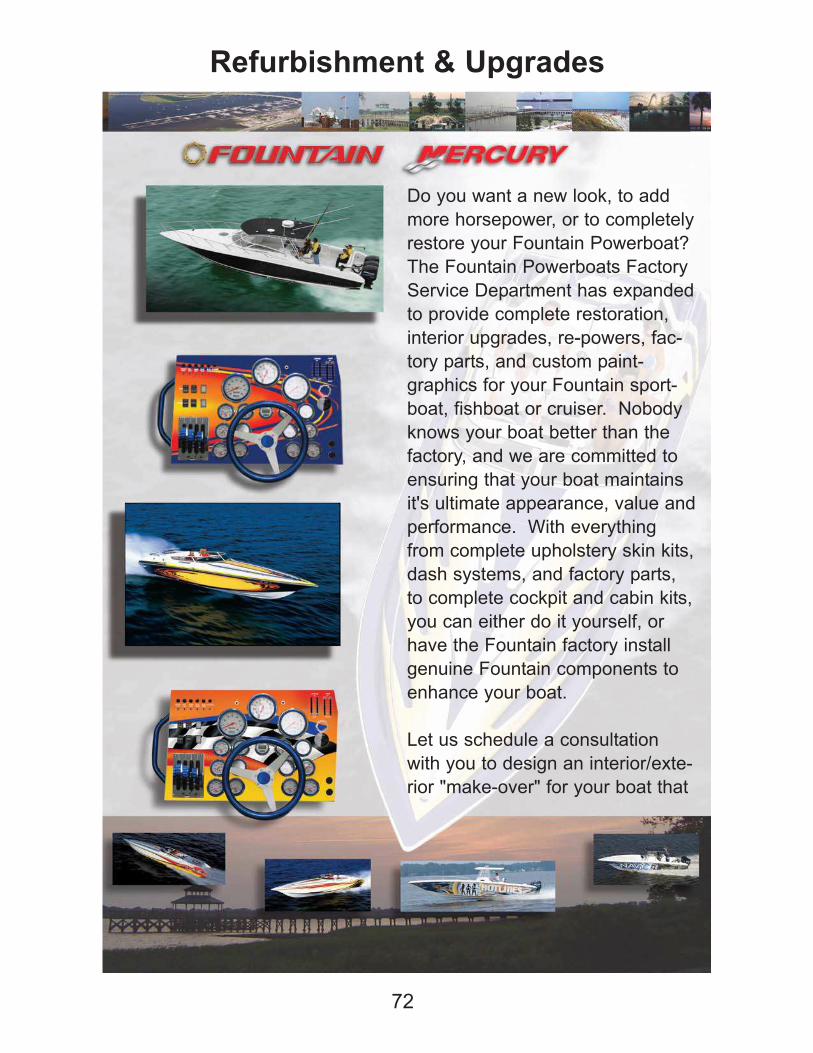
72
Refurbishment & Upgrades
Do you want a new look, to add
more horsepower, or to completely
restore your Fountain Powerboat?
The Fountain Powerboats Factory
Service Department has expanded
to provide complete restoration,
interior upgrades, re-powers, fac-
tory parts, and custom paint-
graphics for your Fountain sport-
boat, fishboat or cruiser. Nobody
knows your boat better than the
factory, and we are committed to
ensuring that your boat maintains
it's ultimate appearance, value and
performance. With everything
from complete upholstery skin kits,
dash systems, and factory parts,
to complete cockpit and cabin kits,
you can either do it yourself, or
have the Fountain factory install
genuine Fountain components to
enhance your boat.
Let us schedule a consultation
with you to design an interior/exte-
rior "make-over" for your boat that
73
Refurbishment & Upgrades
suits your personality and budget. An updated look will add
resale value, and give you that "new boat" look and feel for a
fraction of the cost of a new boat.
In addition to "upgrade" work and parts, we have all of the neces-
sary resources to provide you with maintenance and service on
your Mercury engine drive train components as well as Fountain
and Mercury warranty service.
So whether you want to spruce up your boat's appearance, or
show your friends the transom of your boat in the next poker run
or fishing tournament as you pull away with new power,
Fountain's Service Department is your one-stop-shop for all of
your Fountain Powerboat needs.
Complete Upholstery Skin Kits
Complete Cockpit Kits, Including Bolsters & Hardware
Complete Custom & Standard Dash Panels
Custom and Standard Graphics Packages
Windshields, and Plexi-Glass Components
Towers & Leaning Posts
Custom Powder Coating
Bottom Blueprinting Services
Complete Fiberglass and Mechanical Repair
Specialty Parts, Poker-Run Vests, Racing Vests & Intercoms
Rebuilt 5.0kw Westerbeke Generators
Factory Re-Power, Including Engines and Drives
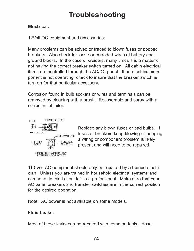
74
Troubleshooting
Electrical:
12Volt DC equipment and accessories:
Many problems can be solved or traced to blown fuses or popped
breakers. Also check for loose or corroded wires at battery and
ground blocks. In the case of cruisers, many times it is a matter of
not having the correct breaker switch turned on. All cabin electrical
items are controlled through the AC/DC panel. If an electrical com-
ponent is not operating, check to insure that the breaker switch is
turn on for that particular accessory.
Corrosion found in bulb sockets or wires and terminals can be
removed by cleaning with a brush. Reassemble and spray with a
corrosion inhibitor.
Replace any blown fuses or bad bulbs. If
fuses or breakers keep blowing or popping,
a wiring or component problem is likely
present and will need to be repaired.
110 Volt AC equipment should only be repaired by a trained electri-
cian. Unless you are trained in household electrical systems and
components this is best left to a professional. Make sure that your
AC panel breakers and transfer switches are in the correct position
for the desired operation.
Note: AC power is not available on some models.
Fluid Leaks:
Most of these leaks can be repaired with common tools. Hose
clamps and wrenches can cure most hose and fitting leaks. Check
all hoses and fitting regularly.
Likely locations for fluid leaks would be in the engine compartment
(water, oils, fuel); under the dash (steering fluid); at the transom
(steering fluid, drive fluid, hydraulic fluid); cabin (water from fresh
water systems, water from faulty hatch seals).
Engine:
Engine will not crank:
Check for battery switch position. They need to be in the on position.
Check volt gauges for at least 10-12 volts with the key on. If low, it
would indicate a bad battery, a draw on the battery causing it to lose
power, charging system problem preventing the battery from being
charged while under way, or shore power charger problem prevent-
ing the battery from being charged while the boat is plugged into
shore power.
Check that the gearshift levers are in Neutral.
Key switch breakers popped. Reset by pressing the rubber breaker
button next to the key switch.
If the engine cranks but does not start, check the position of the safe-
ty lanyard switch, and insure that it is in the run position. (Gasoline
powered boats)
Note: See pre-check section of this manual to avoid most common
problems. Trained technicians should service any major problems.
75
Troubleshooting

Electrical Schematic Diagrams
76

Electrical Schematic Diagrams
77
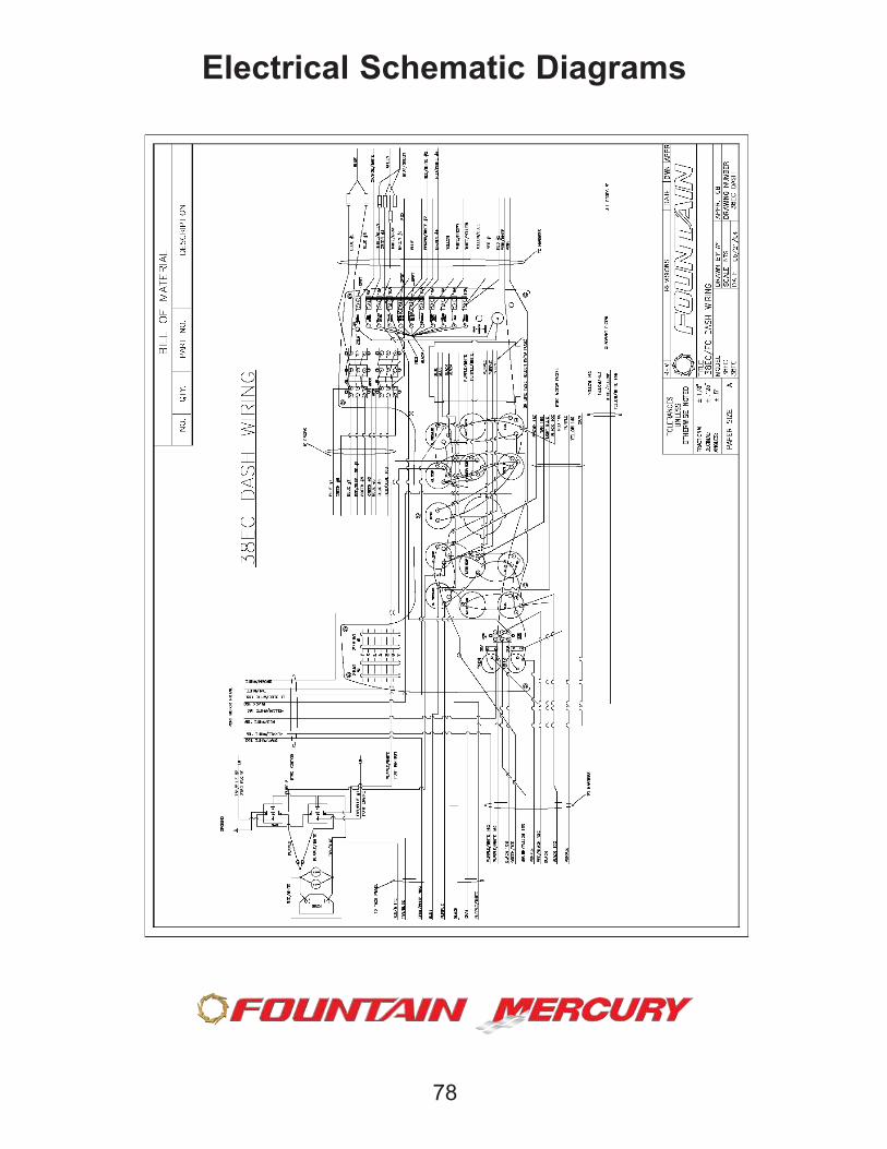
Electrical Schematic Diagrams
78

Electrical Schematic Diagrams
79

Electrical Schematic Diagrams
80

Electrical Schematic Diagrams
81
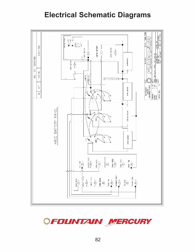
Electrical Schematic Diagrams
82

Electrical Schematic Diagrams
83

Electrical Schematic Diagrams
84

Electrical Schematic Diagrams
85
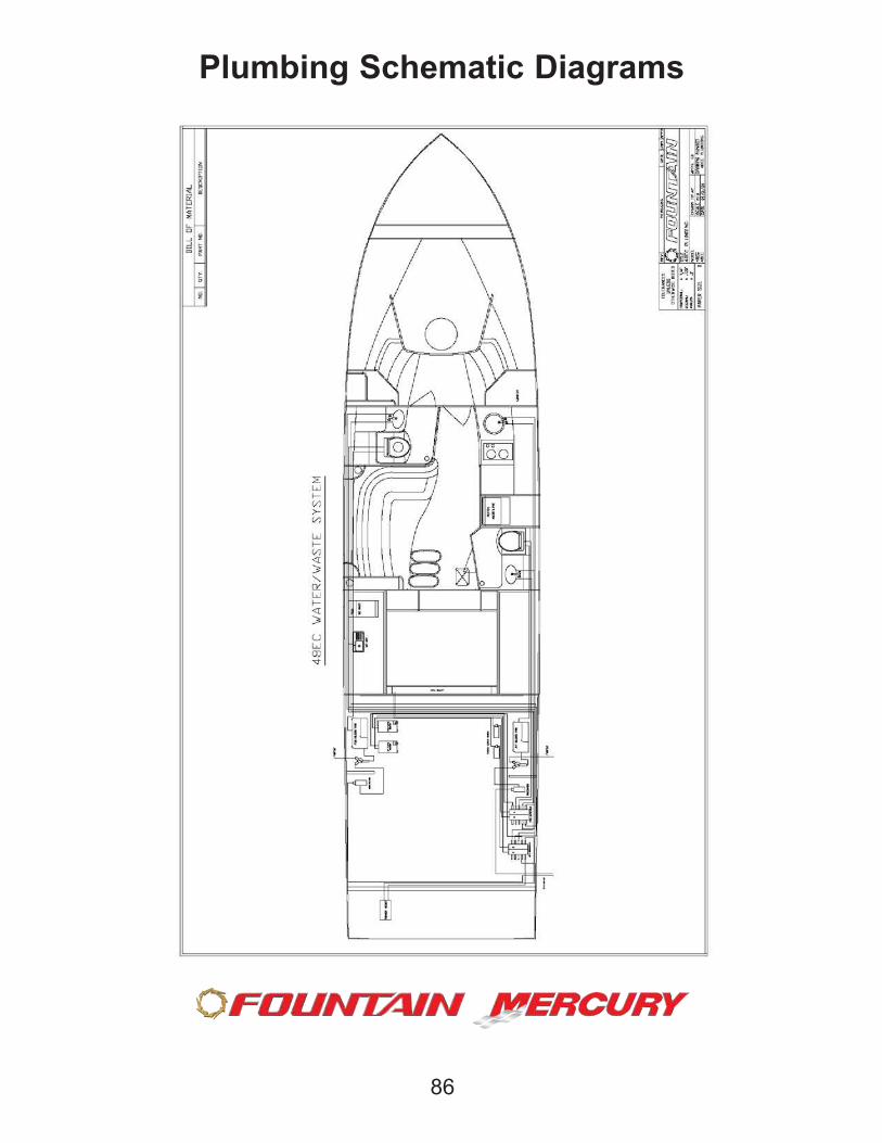
Plumbing Schematic Diagrams
86
THIS MANUAL MAY NOT BE REPRODUCED IN WHOLE OR
IN PART WITHOUT THE EXPRESSED WRITTEN PERMISSION
OF FOUNTAIN POWERBOATS. FOUNTAIN POWERBOATS
RESERVES ALL RIGHTS. COPYRIGHT 2005.
87
THIS MANUAL IS NOT INTENDED TO BE ALL INCLUSIVE, AND
IS NOT A SUBSTITUTE FOR GENERAL BOATING KNOWL-
EDGE OR PRACTICE OF COMMON BOATING SAFETY PROCE-
DURES.
FOUNTAIN POWERBOATS RECOMMENDS BOATERS PARTICI-
PATE IN AN APPROVED UNITED STATES COAST GUARD
BOATING COURSE, AND THAT ALL BOATERS OBSERVE
SAFE BOATING PRACTICES, INCLUDING BOAT HANDLING,
SYSTEMS OPERATION, NAVIGATION, AND MAINTENANCE.
PLEASE BE SURE TO REFER TO THE SPECIFIC OWNERS
MANUALS FOR THE SYSTEMS INCLUDED ON YOUR BOAT
THAT ARE NOT MANUFACTURED BY FOUNTAIN POWER-
BOATS, INCLUDING BUT NOT LIMITED TO THE POWERTRAIN,
GENERATOR SYSTEMS, AIR CONDITIONING SYSTEMS, AC
POWER SYSTEMS, NAVIGATION SYSTEMS, ENTERTAINMENT
SYSTEMS, ETC.
IT IS THE BOAT OWNERS RESPONSIBILITY TO KNOW AND
UNDERSTAND ALL OF THE EQUIPMENT ON BOARD YOUR
BOAT.

Fountain Powerboats, Inc.
P.O. Drawer 457
Washington, NC 27889
252-975-2000
www.fountainpowerboats.com
ASE Symbol: FPB


![Instant Fountain Owners Manual[1]](https://img.pdfslide.net/doc/110x75/577ce7db1a28abf10395ebd2/instant-fountain-owners-manual1.jpg)