Embed Size (px)
DESCRIPTION
electric motors
Citation preview

OPERATION MANUAL
OVERALL AND MOUNTING DIMENSIONS
TYPE AIM 100-280 AND WITH ELECTROMAGNETIC BRAKE TYPE AIFM 100-180
Revizia 1: 28-05-2009 Revizia 2:
CT 4 - 2006
Data elaborării: 21-06-2006
Revizia 3:

SC UMEB SA
Three-phase slip-ring motors for hoisting units drive type AIM frame size 100-280 and with electromagnetic brake type
AIFM frame size 100-180
CT4-2006 Page 1 / 24
OPERATION MANUAL
Safety operating conditions for low voltage three phase asynchronous slip-ring motors
type AIM 100-280 and AIFM 100-180 according to EEC Relevant Directives
These motors have active parts (under voltage), components in rotation and possible hot surfaces. All the works during conveying, installing, commissioning and maintenance shall be done by authorized, skilled, technical personnel. The improper performing of these works can bring about accidents and/or material losses. The non-observance of the provisions of this Operation Manual annuls any liability from the producer for the possible accidents and material losses occurred and in warranty period the non-observance of these provisions brings also about the warranty expiry of the product (motor).
1. Designation 1.1 The present Operation Manual is applied to three-phase asynchronous motors of low voltage with collecting rings for driving AIM-type lifting device gauge 100-280 and with electromagnetic brake type AIFM gauge 100-180. These motors of low voltage are designed to using in industrial devices and they also comply with: - SR EN 60034 – Electric Machines – harmonized standards - GD 119-2004 – regarding the establishment of conditions for bringing on market the industrial machines – that transposes the provisions of Directive 98/37/EEC-Machines - GD 497-2003 – regarding the establishment of conditions for bringing on market and working the electric and electronic apparatus from standpoint of electromagnetic compatibility – that transposes Directive 89/336/EEC-Electromagnetic Compatibility 1.2 The motors are meant to usually working in macro-climate area with temperate climate N, characterized by: - Ambient temperature: -33 C ... +40 C - Relative humidity: max. 80% at +20 C - Altitude: max. 1000 m
2. Main Features The electric and mechanical parameters and the gauge and mounting levels are according to ST 38-2006 for AIM motors and ST39-2006 for AIFM motors and/or UMEB-SA products catalogue, with the following mentions: - Standard nominal functioning service is S3 (6 con/hour, DA=40 %). The motors can be also used for other equivalent services; these equivalent services and their associated powers are mentioned in the Catalogue of UMEB-SA products. - Insulation class of stator and rotor coilings: F - Usual protection degree of motors: minimum IP54 3. Product Description The motors are provided with bearings on ball-bearings, according to table 3.1:
AIM-Type Motors Table 3.1

SC UMEB SA
Three-phase slip-ring motors for hoisting units drive type AIM frame size 100-280 and with electromagnetic brake type
AIFM frame size 100-180
CT4-2006 Page 2 / 24
Gauge Driving bearing Support bearing
100 6306 P6 EL 6306 P6 EL 112 6307 2Z P63 EL 6307 2Z P63 EL 132 6308 2Z P63 EL 6308 2Z P63 EL 160 6310 2Z P63 EL 6310 2Z P63 EL 180 6311 2Z P63 EL 6311 2Z P63 EL 200 6312 P6 6312 P6 225 6313 P6 6313 P6 250 NU 315 P6 6315 P6 280 NU 317 P6 6317 P6
AIFM-Type Motors Table 3.1 (follow-on)
Gauge Driving bearing Support bearing
100 6306 P6 EL 6306 P6 EL 112 6307 2Z P63 EL 6307 2Z P63 EL 132 6308 2Z P63 EL 6308 2Z P63 EL 160 6310 2Z P63 EL 6310 2Z P63 EL 180 6311 2Z P63 EL 6311 2Z P63 EL
In table 3.2 there are shown the type and dimensions of brushes equipping motors of type AIM and AIFM:
Table 3.2
Gauge
Motor type
Brush type
Brush dimensions
Brush height
100 AIM , AIFM P100 16 x 8 25 112 AIM , AIFM P112 16 x 8 25 132 AIM , AIFM P132 20 x 10 32 160 AIM , AIFM P160 25 x 12,5 32 180 AIM , AIFM P180 25 x 12,5 32 200 AIM P200 32 x 16 40 225 AIM P225 32 x 16 40 250 AIM P250 40 x 20 50 280 AIM P280 40 x 20 50
4. Instrumentation When commissioning and within the maintenance works it is required the following instrumentation: - Mega-ohmmeter of 1000 V for measuring the insulation strength - Voltmeter for checking the supply voltage - Ammeter for measuring currents on phase - Tachometer for measuring the rotation speed
5. Special Tools and Spare Parts 5.1 Among tools necessary for dismounting and mounting the motors we specify the kits of wrenches and tubular spanners for hexagonal head screws, cylindrical head screws and
SC UMEB SA
Three-phase slip-ring motors for hoisting units drive type AIM frame size 100-280 and with electromagnetic brake type
AIFM frame size 100-180
CT4-2006 Page 3 / 24
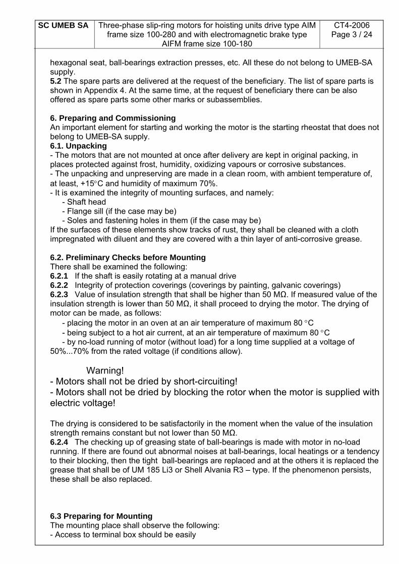
hexagonal seat, ball-bearings extraction presses, etc. All these do not belong to UMEB-SA supply. 5.2 The spare parts are delivered at the request of the beneficiary. The list of spare parts is shown in Appendix 4. At the same time, at the request of beneficiary there can be also offered as spare parts some other marks or subassemblies. 6. Preparing and Commissioning An important element for starting and working the motor is the starting rheostat that does not belong to UMEB-SA supply. 6.1. Unpacking - The motors that are not mounted at once after delivery are kept in original packing, in places protected against frost, humidity, oxidizing vapours or corrosive substances. - The unpacking and unpreserving are made in a clean room, with ambient temperature of, at least, +15C and humidity of maximum 70%. - It is examined the integrity of mounting surfaces, and namely: - Shaft head - Flange sill (if the case may be) - Soles and fastening holes in them (if the case may be) If the surfaces of these elements show tracks of rust, they shall be cleaned with a cloth impregnated with diluent and they are covered with a thin layer of anti-corrosive grease. 6.2. Preliminary Checks before Mounting There shall be examined the following: 6.2.1 If the shaft is easily rotating at a manual drive 6.2.2 Integrity of protection coverings (coverings by painting, galvanic coverings) 6.2.3 Value of insulation strength that shall be higher than 50 MΩ. If measured value of the insulation strength is lower than 50 MΩ, it shall proceed to drying the motor. The drying of motor can be made, as follows: - placing the motor in an oven at an air temperature of maximum 80 C - being subject to a hot air current, at an air temperature of maximum 80 C - by no-load running of motor (without load) for a long time supplied at a voltage of 50%...70% from the rated voltage (if conditions allow). Warning! - Motors shall not be dried by short-circuiting! - Motors shall not be dried by blocking the rotor when the motor is supplied with electric voltage! The drying is considered to be satisfactorily in the moment when the value of the insulation strength remains constant but not lower than 50 MΩ. 6.2.4 The checking up of greasing state of ball-bearings is made with motor in no-load running. If there are found out abnormal noises at ball-bearings, local heatings or a tendency to their blocking, then the tight ball-bearings are replaced and at the others it is replaced the grease that shall be of UM 185 Li3 or Shell Alvania R3 – type. If the phenomenon persists, these shall be also replaced. 6.3 Preparing for Mounting The mounting place shall observe the following: - Access to terminal box should be easily

SC UMEB SA
Three-phase slip-ring motors for hoisting units drive type AIM frame size 100-280 and with electromagnetic brake type
AIFM frame size 100-180
CT4-2006 Page 4 / 24
- Not to be hampered the motor ventilation - Not to be near heat sources - To allow the access for surveillance and maintenance Before mounting, the motor shall be dry compressed-air blown to remove the impurities. It is checked if data of indicating plate correspond to driving: Power Rotation speed Working service Voltage and frequency Connection 6.4 Connecting to Electric Energy Supply Network and to Starting Rheostat 6.4.1 Stator is connected to electric energy supply network being observed the value of voltage and connection written on indicating plate. The connection of supply conductors is made, as follows: - It is dismounted the cap of terminal box with a special spanner for screws. - It is dismounted the pressing device with a wrench, there are removed the pressing ring, the wall and the sealing gasket. -There are passed over cable the pressing device, the pressing ring and the sealing gasket, it is inserted the feeder cable in the terminal box. -There are inserted in their seat the sealing gasket, the pressing ring and the pressing device. By tightening, the pressing device presses on the rubber gasket and this one is distorted and presses on cable being provided the sealing of the terminal box. - The feeding conductors equipped with clips proper to section of cables and dimension of terminals are fastened to terminal plate being used a spanner for hexagonal nuts. 6.4.2. The rotor winding shall be connected to the starting rheostat by means of the 3 terminals of brush-holder. The starting rheostat connection to the 3 terminals of brush-holder shall be also made by pressing device and by means of electric clips chosen properly to section of rheostat cable and sizes of the 3 terminals of brush-holder similarly as proceeded at electric energy supply cable. The starting rheostat is chosen in such a way so that to provide a start up in 3...5 steps, that should limit the starting current at max. 1.5 from the nominal current of motor, and the start up should not last more than 10 seconds. At the same time, the starting rheostat shall bear the rotor voltage and the rotor current properly, according to catalogue. 6.4.3 It is connected the protecting conductor to earthing terminal provided in the terminal box. Before connecting, the protecting conductor shall be equipped with an electric clip corresponding to cable section and sizes of earthing terminal. At the same time, also before connecting, all the contact surfaces shall be cleaned up to metallic glaze, afterwards these shall be lubricated with a layer of conducting grease (e.g. copper grease). Providing a good earthing contact shall be made by tightening the earthing screw in terminal box according to table 6.7.3. - It is mounted the cap of the terminal box. 6.5 Connecting to Earthing Terminal on Housing - It is made with a multicore cable (conductor) with low strength, according to norms of labour protection, in places marked with conventional sign of grounding where there are placed the earthing terminals. - Before connecting to earthing terminal provided on housing, the earthing conductor shall be equipped with an electric clip corresponding to cable section and dimension of earthing terminal. At the same time, also before connecting, all the contact surfaces shall be cleaned up to metallic glaze, afterwards these shall be lubricated with a layer of conducting grease (e.g. copper grease). Providing a good earthing contact shall be made by tightening the earthing screw on housing according to table 6.7.3. 6.6 Protection against Overload

SC UMEB SA
Three-phase slip-ring motors for hoisting units drive type AIM frame size 100-280 and with electromagnetic brake type
AIFM frame size 100-180
CT4-2006 Page 5 / 24
The motors shall be protected against overload currents by user. 6.7 Checking the Mounting
Before connecting the motor to network, there are recommended the following check-ups: 6.7.1 All the fastening parts of motor should be tightened. The values of tightening couplings for threaded joints are shown in table 6.7.1. The screws becoming unusable shall be replaced by other new ones with the same quality class (min.8.8) and of the same type. Table 6.7.1 Threaded joints of quality class 8.8 for cast iron or steel component
Thread size Tightening coupling [Nm]
M4 2.3 M5 4.5 M6 7.9 M8 19
M10 38 M12 68 M14 105 M16 160
6.7.2 The coupling with driven mechanism must be rightly performed. It shall be paid a special attention to alignment of rotation axis of motor with the rotation axis of the driven mechanism in order to be avoided the emerging of vibrations, noises and additional loads at the motor shaft and in its ball-bearings. 6.7.3 The screws and nuts providing the electric contacts should be tightened with values of tightening couplings according to table 6.7.3, and the earthing should be rightly made.
Table 6.7.3 Threaded joints for electric connections
Thread size Tightening coupling [Nm]
M4 1,2 M5 2 M6 3 M8 6
M10 10 M12 15,5
6.7.4 All the parts bearing current should be covered, insulated and protected against touching with hand. 6.7.5 All the connecting apparatus should be on „0” or „disconnected” position. 6.7.6 The apertures of fan bonnet should not be obturated. 6.7.7 The starting rheostat should be connected to the 3 terminals of brush-holder and it should be on the maximum position of resistance. 6.7.8 The brushes should make a very good contact with the 3 collecting rings. The brushes are chosen in such a way so that not to wear excessively the collecting rings. The brushes shall be changed in the moment when their wearing reached approximately 50% from their height. - After checking the observance of all these conditions it is made a testing start-up in no-load running for 3 hours of continuous running. In this case, it must be noticed and checked if

SC UMEB SA
Three-phase slip-ring motors for hoisting units drive type AIM frame size 100-280 and with electromagnetic brake type
AIFM frame size 100-180
CT4-2006 Page 6 / 24
there are not abnormal noises because of some abnormal frictions of parts. A special attention shall be paid to brush-collecting ring sliding contacts. - At the same time there shall be checked the vibrations of motor and the heatings of ball-bearings. - After continuous no-load running as test, it is required to be made a number of 10....15 start-ups and direction reversals (also in no-load) with the starting rheostat on the maximum value of resistance. If, at the test operations, the motor is working normally, without noises and abnormal vibrations, then the motor can be commissioned. 7. Possible Defects and Way of Repairing Table 7
No. Defect Cause of appearing Way of remedying a. Blocked ball-bearings There shall be changed the ball-
bearings b. Worn-out grease The non-tight ball-bearings shall be
washed and greased again. The tight ball-bearings shall be replaced.
c. Distorted fan bonnet making contact to fan
The distorted bonnet shall be replaced or remedied.
1. Axis does not rotate freely (in case of AIM-type motors)
d. One or several brushes or brush-holder boxes make contact to insulating rings (gauge160....280)
There shall be adjusted the brush-holders in such a way so that the brushes should walk in the middle of the collecting rings.
a. Motor is supplied only in two phases or the supply voltage is too low
There shall be checked the connections to terminal box and it shall be checked the presence of proper values of voltages of the three phases of supply network with a voltmeter.
b. Starting rheostat is not connected properly to brush-holder terminals or it is out-of-order
There shall be checked the connections of the starting rheostat to the terminals of brush-holder and it shall be checked if the starting rheostat is on the maximum position of resistance. The starting rheostat shall be remedied or replaced.
2. Motor does not start in no-load
c. Rotor is blocked It shall be checked if the lifting device is running properly. It shall be checked if the brake is working properly (in case of AIFM-type motors).
a. There shall be seen the causes from no. 2.
There shall be made the check-ups from no. 2
b. Improper selection of motor There shall be made the required check-ups.
3. Motor does not start in on-load
c. Load is too high for motor (and lifting device)
There shall be made the required check-ups. The brake shall be checked and adjusted (in case of AIFM-type

SC UMEB SA
Three-phase slip-ring motors for hoisting units drive type AIM frame size 100-280 and with electromagnetic brake type
AIFM frame size 100-180
CT4-2006 Page 7 / 24
motors).
a. Value of supply voltage or frequency is too low
There shall be checked the supply voltage and frequency that must correspond to rated voltage and frequency of motor written on label.
b. Motor load is higher than the rated one
There shall be made the required check-ups. The brake shall be checked and adjusted (in case of AIFM-type motors).
4. Rotation speed of motor in on-load is reduced
c. Feeder cable is not properly dimensioned (significant voltage drop on cable)
It shall be selected a cable with an adequate section (larger).
a. Faulty contacts in one or several supply points of stator or rotor circuit
There shall be checked the electric circuits of stator and rotor.
5. Motor has unequal currents on phase b. Short-circuit between the
coils of the stator or rotor windings
There shall be checked the windings of stator and rotor and they shall be rewound, depending on case.
a. Faulty coupling The coupling shall be checked. b. Damaged ball-bearings There shall be replaced the ball-
bearings. c. Unbalanced rotor It shall be balanced the rotor.
6. Motor is vibrating, has noise
d. Fan has broken blades It shall be changed the fan. a. a. There shall be seen the causes from no. 3.
There shall be made the check-ups from no. 3.
b. Short-circuit between the coils of the stator or rotor windings
The faulty windings shall be rewound.
c. Improper adjustment of protection apparatuses
There shall be adjusted the protection apparatuses.
7. Protection apparatus disconnects the motor
d. Brake does not work The brake shall be checked and adjusted (in case of AIFM-type motors).
a. Long standing in medium with high humidity
The motor shall be dried after having removed water from the inside of motor (if the case may be) and after having wiped and cleaned the brushes and the collecting rings.
8. Low insulation resistance
b. Penetration of water in motor
It shall be removed water from the inside of motor, then this one shall be dried.
a. Obturated bonnet There shall be removed the objects obturating the bonnet apertures.
b. Housing full of dust or other residues that hamper the ventilation and cooling of motor
It shall be cleaned the housing from dust or other impurities.
c. Fan has broken blades The fan shall be replaced. l
9. Excessive heating of motor
d. Motor does not work under running conditions inscribed on data specifying label
There shall be observed the running conditions inscribed on label with motor specifying data.

SC UMEB SA
Three-phase slip-ring motors for hoisting units drive type AIM frame size 100-280 and with electromagnetic brake type
AIFM frame size 100-180
CT4-2006 Page 8 / 24
Observation: For AIFM-type motors the check-ups and the adjustment of brakes shall be made according to adjusting and operating instructions of brakes, depending on brake type the motor is equipped with, enclosed to this Technical Book. 8. Motor Dismounting The motor dismounting shall be made according to Appendices 1 , 2 and 3 depending on the specified motor type.
Warning! Do not dismount motors when they are under electric voltage.
8.1 Change of Brushes - It is dismounted the cap of terminal box. - There are lifted the levers that push down and press the brushes. - With a hexagonal spanner there are unscrewed and dismounted the clips of the connections of the brushes on the brush-holder terminals. - The brushes are removed and replaced with brushes of the same type supplied by UMEB-SA. 8.2 Dismounting the Brush-Holder Subassembly - The brushes are taken out of brush-holder cases. - Then, the brush-holder subassembly is dismounted by complete unscrewing of the two fastening screws from its ends. - When mounting (replacing) the whole brush-holder subassembly, this one shall be positioned (adjusted) in such a way so that all the brushes should make a good contact with the collecting rings but, at the same time, not to be contacts between the insulating rings and the steady parts of the brush-holder that can be materialized in frictions and noises during working. 8.2 Fan Dismounting - It is dismounted the fan bonnet after having previously dismounted the lubricator at the devices at which the ball-bearings can be lubricated during working. - It is removed the retaining ring. - It is extracted the fan on shaft end and up to fan by means of an adequate extractor. 8.3 Rotor Dismounting - The dismounting is made in the order shown in Appendices 1, 2 and 3. - The traction shields and the fan are removed from housing either by means of a special press with tie rods and central screw or manually. The extraction is made slightly pulling the shield equally being thus avoided the damage of joining surfaces or the damage of ball-bearings. 8.4 Ball Bearing Dismounting For dismounting the ball bearings on shaft it shall be used a claw press. 8.5 Dismounting the Subassembly of Collecting Rings - After dismounting the fan ball bearing it is removed the safety device of the collecting ring subassembly. - There are unscrewed the clips of the connections of the rotor winding on the three contact lamellae of the collecting rings by means of a hexagonal spanner. - It is extracted the collecting ring subassembly by extracting also by means of a press. 8.6 Brake Dismounting (only in case of AIFM-type motors) - Before dismounting (mechanically) the brake there shall be removed its electric connections. - Then, there shall be removed the dowel pins that tighten the brake by unscrewing. After dismounting the brake from the fan shield, the retaining ring (that fastens the brake driver to

SC UMEB SA
Three-phase slip-ring motors for hoisting units drive type AIM frame size 100-280 and with electromagnetic brake type
AIFM frame size 100-180
CT4-2006 Page 9 / 24
rotor) shall be removed from the shaft and, then, by means of a press it shall be extracted the brake driver from the motor shaft (according to Appendix 3). 8.6 Motor Mounting It shall be made in reverse order to motor dismounting (see Appendices 1, 2 and 3). 9. Maintenance and Servicing Rules - A special attention shall be paid to brush-collecting ring sliding contact. The brushes shall be replaced after their wearing reached approx. 50 % from height. The collecting rings shall be usually replaced when there occur the following defects: - Penetration of insulation between collecting rings or between the collecting rings and their metallic bushing - Flash over of insulation between collecting rings - Holes or distortions of cylindrical surface of contact - It shall be paid a special attention to maintenance of ball-bearings, monitoring the heating and noise generated by them. - For a right working of ball-bearings it is required the maintenance of a high degree of cleaning, any operation on ball-bearings being made in atmosphere free of dust with dry and clean tools and recipients. - The motors of gauges 250-280 are equipped with system allowing lubrication during working. The type of grease recommended for re-lubrication of ball-bearings is UM 185 Li3 according to STAS 12721-89 or similar, equivalent greases such as Shell Alvania R3, SKF LGTH 3 or UTJ 185 Li2/3. The chart for grease completion and the re-lubricating periods are shown in table 9, according to instructions in the catalogue of the ball-bearing producer. Table 9
Working conditions
Motor type
Ball-bearing Rotation speed [rpm]
Hours/ day
[hours] (maxi-mum)
Ball-bearing working
temperature [C]
Re-lubrica-
ting period [days]
Comple-ting period
[days]
Grease quantity
[g]
NU 315 P6 ≤1500 Normal 63 ÷ 78 462 80 AIM 250
6315 P6 ≤1500 Normal 63 ÷ 78 462 80
30
NU 317 P6 ≤1500 Normal 63 ÷ 78 408 71 AIM 280
6317 ≤1500
24
Normal 63 ÷ 78 408 71 37
- In case of tight ball-bearings (enclosed - 2Z) these shall be replaced after being worn-out with ball-bearings of the same type. - The joining sills of shields with the housing shall be cleaned and re-lubricated with protection grease after each dismounting. - Periodically it is checked the insulation resistance, the value under 50 MΩ showing some defects either of depositing dirt on the insulating surfaces or penetrating the humidity in coiling. It shall be proceeded to drying the motor according to item 6.2.3 We recommend to be made the following periodical check-ups Weekly

SC UMEB SA
Three-phase slip-ring motors for hoisting units drive type AIM frame size 100-280 and with electromagnetic brake type
AIFM frame size 100-180
CT4-2006 Page 10 / 24
- There shall be checked up the sliding contacts of brushes-collecting rings, the state and wearing of brushes, the state and aspect of the collecting rings; if brushes show wearing of 50 % from height they shall be replaced; when the brushes are replaced, there shall be also cleaned the collecting brushes with abrasive paper (fine granulation: 500) applied on a piece of wood having the width of rings in order to provide a plane surface of contact. - There shall be cleaned the inlet apertures of cooling air of fan bonnet and the space between the housing ribs. - There shall be checked up the working conditions, the current absorbed by motor, the voltage and the supply frequency as against those specified on the indicating labels. - There shall be checked up the insulation resistances of stator and rotor windings. Monthly - There shall be checked up all the connections in the terminal box (of stator, rotor windings, including the connection to earthing terminal). - Quarterly - There shall be checked up the motor fastening and mechanical coupling with the lifting device, the normal working of ball-bearings, the tightening of screws for fastening the shields, the fan bonnet, the terminal box. Annually - It shall be made the general revision, with dismounting and detailed examination of the component parts and replacement of the faulty ones, there shall be replaced the worn out brushes, there shall be cleaned the collecting rings. - There shall be cleaned the parts that show tracks of rust and they shall be re-covered by painting or electro-chemically, depending on case. - The coilings shall be cleaned. - There shall be checked up, cleaned the grease and lubricated the ball-bearings or they shall be replaced, depending on case. - There shall be checked up the sealing gaskets from the cable inlets.
10. Marking, Packing, Conveying, Storing, Preserving - Marking – The motors are provided with a plate with indicating data on the outside of housing. - Packing – The motors are delivered unpacked or packed according to contractual provisions. - Conveying – The conveying shall be compulsorily made by covered motor-vehicles and they shall be very well fixed on their platform being avoided the shocks during loading and unloading handlings. - Storing – Up to mounting, the motors shall be stored in original packing, in rooms with humidity of maximum 80% (at +25C), without gases and anti-corrosive vapours, at temperatures between -5 C....+40 C - Preserving – If the motors are stored for a long time in a place that is not dry, these shall be covered with a polyethylene cover inside of which there shall be placed bags with humidity absorbing substances (silica gel).
11. Rules of Labour Protection - CONNECTING THE MOTOR TO ELECTRIC ENERGY SUPPLY NETWORK AND PUTTING IN OPERATION SHALL BE MADE ONLY BY SKILLED AND AUTHORIZED PERSONNEL FOR PERFORMING WORKS IN ELECTRIC INSTALLATIONS. - Before putting in operation it shall be checked the accuracy of connections to protecting installation (grounding both in terminal box and on housing). It is forbidden the operating of

SC UMEB SA
Three-phase slip-ring motors for hoisting units drive type AIM frame size 100-280 and with electromagnetic brake type
AIFM frame size 100-180
CT4-2006 Page 11 / 24
motors if there were not made the connections to screws for connecting to protecting null and grounding. - During motor running the components under moving (drawn by motor) shall be protected against accidental touches. - It is forbidden the opening of cap of terminal box during motor running or when this one is under voltage. - It is not allowed the motor operating without being properly mounted the cap of terminal box or fan bonnet as well. - Any intervention to motor shall be made only after its taking out of voltage.

SC UMEB SA
Three-phase slip-ring motors for hoisting units drive type AIM frame size 100-280 and with electromagnetic brake type
AIFM frame size 100-180
CT4-2006 Page 12 / 24
AIM-Type Motors
Technical Features
Motor type Pn kW
Nn rot/min
I1 (A)
η %
cosφ Mmax/Mn
U2 (V)
GD2 kgfm2
Weightkg
2p=4 (1500rot/min) AIM 100La-4 2 1310 7 68 0.65 2.9 110 0.14 42 AIM 100Lb-4 2.5 1340 8.1 69 0.68 2.7 115 0.16 46 AIM 112Ma-4 3.2 1340 10.1 71.5 0.67 2.6 120 0.18 56 AIM 112Mb-4 4 1350 11.3 77 0.70 3.0 130 0.2 61 AIM 132Sa-4 5 1350 14 74 0.73 3.2 145 0.22 90 AIM 132Ma-4 6.3 1390 17.2 76.5 0.73 2.8 160 0.25 100 AIM 132Mb-4 8 1400 20 82.5 0.74 3.6 170 0.3 125 AIM 160M-4 10 1400 23.5 83 0.78 3.8 180 0.55 170 AIM 160L-4 15 1420 35.7 84 0.76 3.2 260 0.65 190 AIM 180L-4 20 1420 43.1 86 0.82 3.0 270 1 215 AIM 200La-4 24 1420 47.2 89 0.87 3.2 230 1.6 350 AIM 200L-4 25 1420 48.5 89 0.88 3.2 230 1.6 367 AIM 200Lb-4 28 1420 55 89 0.87 3.0 275 1.75 367 AIM 225Ma-4 32 1440 62 89 0.88 2.8 275 2.5 375 AIM 225Mb-4 39 1440 76 90.5 0.87 2.9 330 3.2 388 AIM 250M-4U 48 1460 105 88 0.79 3.0 195 4.5 540 AIM 250M-4V 58 1460 137 88 0.73 4.0 235 5.5 582 AIM 280S-4 75 1470 141 92 0.88 2.5 280 9.7 700 AIM 280M-4 85 1470 158 92 0.90 2.6 300 11 760
2p=6 (1000rot/min) AIM 100La-6 1.25 880 4.1 67 0.68 2.7 80 0.18 42 AIM 100Lb-6 1.6 880 4.8 72 0.70 2.6 85 0.2 46 AIM 112Ma-6 2 880 5.7 75 0.72 2.7 95 0.23 56 AIM 112Mb-6 2.5 880 8.0 70.4 0.67 3.5 105 0.25 61 AIM 132Sa-6 3.2 900 9.8 71 0.70 2.8 110 0.28 90 AIM 132Ma-6 4 900 11.2 77 0.70 2.8 115 0.3 100 AIM 132Mb-6 5 900 13.7 76 0.73 2.7 120 0.33 125 AIM 160M-6 7.5 920 18 79 0.76 2.6 180 0.6 170 AIM 160L-6 10 920 23.2 83 0.79 2.6 260 0.8 190 AIM 180L-6 15 930 35.3 86 0.8 3.0 230 1.3 215 AIM 200L-6 20 950 42.6 86.4 0.83 3.8 255 1.7 356 AIM 225Ma-6 25 950 49 89.5 0.87 2.4 250 3.4 368 AIM 225Mb-6 30 950 59 89 0.87 2.7 290 3.7 380 AIM 250M-6U 37 970 78 88 0.82 3.9 140 5.1 545 AIM 250M-6V 45 970 103 85 0.78 3.2 175 7 595 AIM 280S-6 60 970 133 89 0.77 2.8 190 11 700 AIM 280M-6 75 970 158 89.4 0.81 2.8 235 14 760
2p=8 (750rot/min) AIM 132Sb-8 2.5 660 8.6 68 0.65 2.8 100 0.28 90
SC UMEB SA
Three-phase slip-ring motors for hoisting units drive type AIM frame size 100-280 and with electromagnetic brake type
AIFM frame size 100-180
CT4-2006 Page 13 / 24
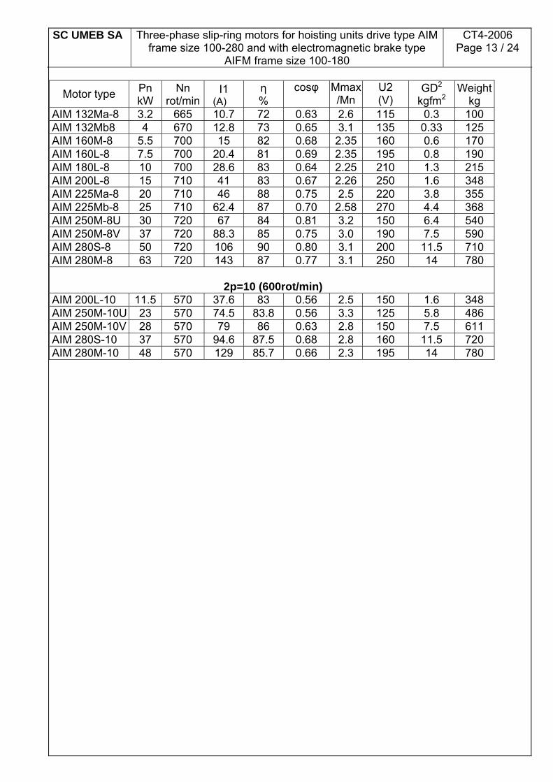
Motor type Pn kW
Nn rot/min
I1 (A)
η %
cosφ Mmax/Mn
U2 (V)
GD2 kgfm2
Weightkg
AIM 132Ma-8 3.2 665 10.7 72 0.63 2.6 115 0.3 100 AIM 132Mb8 4 670 12.8 73 0.65 3.1 135 0.33 125 AIM 160M-8 5.5 700 15 82 0.68 2.35 160 0.6 170 AIM 160L-8 7.5 700 20.4 81 0.69 2.35 195 0.8 190 AIM 180L-8 10 700 28.6 83 0.64 2.25 210 1.3 215 AIM 200L-8 15 710 41 83 0.67 2.26 250 1.6 348 AIM 225Ma-8 20 710 46 88 0.75 2.5 220 3.8 355 AIM 225Mb-8 25 710 62.4 87 0.70 2.58 270 4.4 368 AIM 250M-8U 30 720 67 84 0.81 3.2 150 6.4 540 AIM 250M-8V 37 720 88.3 85 0.75 3.0 190 7.5 590 AIM 280S-8 50 720 106 90 0.80 3.1 200 11.5 710 AIM 280M-8 63 720 143 87 0.77 3.1 250 14 780
2p=10 (600rot/min)
AIM 200L-10 11.5 570 37.6 83 0.56 2.5 150 1.6 348 AIM 250M-10U 23 570 74.5 83.8 0.56 3.3 125 5.8 486 AIM 250M-10V 28 570 79 86 0.63 2.8 150 7.5 611 AIM 280S-10 37 570 94.6 87.5 0.68 2.8 160 11.5 720 AIM 280M-10 48 570 129 85.7 0.66 2.3 195 14 780

SC UMEB SA
Three-phase slip-ring motors for hoisting units drive type AIM frame size 100-280 and with electromagnetic brake type
AIFM frame size 100-180
CT4-2006 Page 14 / 24
AIFM-Type Motors
Technical Features
Motor type Pn kW
Nn rot/min
I1 (A)
η %
cosφ Mmax/Mn
Mf Nm
U2 (V) GD2
kgfm2
Weight*
kg
2p=4 (1500rot/min) AIFM 100La-4 2 1310 7 68 0.65 2.9 35 110 0.184 55 AIFM 100Lb-4 2.5 1340 8.1 69 0.68 2.7 35 115 0.20 59 AIFM 112Ma-4 3.2 1340 10.1 71.5 0.67 2.6 60 120 0.20 69 AIFM 112Mb-4 4 1350 11.3 77 0.70 3.0 60 130 0.22 74 AIFM 132Sa-4 5 1350 14 74 0.73 3.2 100 145 0.24 115 AIFM 132Ma-4 6.3 1390 17.2 76.5 0.73 2.8 100 160 0.27 135 AIFM 132Mb-4 8 1400 20 82.5 0.74 3.6 100 170 0.32 140 AIFM 160M-4 10 1400 23.5 83 0.78 3.8 300 180 0.60 200 AIFM 160L-4 15 1420 35.7 84 0.76 3.2 300 260 0.70 220 AIFM 180L-4 20 1420 43.1 86 0.82 3.0 300 270 1.15 245
2p=6 (1000rot/min)
AIFM 100La-6 1.25 880 4.1 67 0.68 2.7 35 80 0.21 55 AIFM 100Lb-6 1.6 880 4.8 72 0.70 2.6 35 85 0.22 59 AIFM 112Ma-6 2 880 5.7 75 0.72 2.7 60 95 0.24 69 AIFM 112Mb-6 2.5 880 8.0 70.4 0.67 3.5 60 105 0.27 74 AIFM 132Sa-6 3.2 900 9.8 71 0.70 2.8 100 110 0.30 115 AIFM 132Ma-6 4 900 11.2 77 0.70 2.8 100 115 0.32 125 AIFM 132Mb-6 5 900 13.7 76 0.73 2.7 100 120 0.35 150 AIFM 160M-6 7.5 920 18 79 0.76 2.6 300 180 0.65 200 AIFM 160L-6 10 920 23.2 83 0.79 2.6 300 260 0.90 220 AIFM 180L-6 15 930 35.3 86 0.8 3.0 300 230 1.4 245
2p=8 (750rot/min)
AIFM 132Sb-8 2.5 660 8.6 68 0.65 2.8 100 100 0.30 115 AIFM 132Ma-8 3.2 665 10.7 72 0.63 2.6 100 115 0.32 135 AIFM 132Mb-8 4 670 12.8 73 0.65 3.1 100 135 0.35 140 AIFM 160M-8 5.5 700 15 82 0.68 2.35 300 160 0.65 200 AIFM 160L-8 7.5 700 20.4 81 0.69 2.35 300 195 0.90 220 AIFM 180L-8 10 700 28.6 83 0.64 2.25 300 210 1.40 245
* The motor weight depends on brake weight; in table it is the maximum weight (including brake weight).

SC UMEB SA
Three-phase slip-ring motors for hoisting units drive type AIM frame size 100-280 and with electromagnetic brake type
AIFM frame size 100-180
CT4-2006 Page 15 / 24
Appendix 4
List of Spare Parts 1. The brushes are specified in the below table:
Gauge
Motor type
Brush type
Brush sizes
Brush height
100 AIM , AIFM P100 16 x 8 25 112 AIM , AIFM P112 16 x 8 25 132 AIM , AIFM P132 20 x 10 32 160 AIM , AIFM P160 25 x 12,5 32 180 AIM , AIFM P180 25 x 12,5 32 200 AIM P200 32 x 16 40 225 AIM P225 32 x 16 40 250 AIM P250 40 x 20 50 280 AIM P280 40 x 20 50
2. Brush-holder subassembly The Beneficiary shall specify in order the type, power and rotation speed of motor for identification of brush-holder subassembly. 3.The collecting rings of subassembly are specified below:
Gauge
Motor type
Size of collecting ring subassembly
100 AIM , AIFM 63 x 20 112 AIM , AIFM 71 x 20 132 AIM , AIFM 80 x 25 160 AIM , AIFM 100 x 32 180 AIM , AIFM 112 x 32 200 AIM 125 x 20 225 AIM 140 x 20 250 AIM 160 x 25 280 AIM 180 x 25
4. The ball-bearings are specified below: For AIM –type motors

SC UMEB SA
Three-phase slip-ring motors for hoisting units drive type AIM frame size 100-280 and with electromagnetic brake type
AIFM frame size 100-180
CT4-2006 Page 16 / 24
Gauge Driving bearing Support bearing
100 6306 P6 EL 6306 P6 EL 112 6307 2Z P63 EL 6307 2Z P63 EL 132 6308 2Z P63 EL 6308 2Z P63 EL 160 6310 2Z P63 EL 6310 2Z P63 EL 180 6311 2Z P63 EL 6311 2Z P63 EL 200 6312 P6 6312 P6 225 6313 P6 6313 P6 250 NU 315 P6 6315 P6 280 NU 317 P6 6317 P6
For AIFM-type motors
Gauge Driving bearing Support bearing
100 6306 P6 EL 6306 P6 EL 112 6307 2Z P63 EL 6307 2Z P63 EL 132 6308 2Z P63 EL 6308 2Z P63 EL 160 6310 2Z P63 EL 6310 2Z P63 EL 180 6311 2Z P63 EL 6311 2Z P63 EL
5.The terminal plates used are with 6 terminals.
Gauge
Motor type
Size of terminal threads
100 AIM , AIFM M5 112 AIM , AIFM M5 132 AIM , AIFM M6 160 AIM , AIFM M6 180 AIM , AIFM M8 200 AIM M10 225 AIM M10 250 AIM M10 280 AIM M10
6. The packing glands used are of plastic according to the below table:
Gauge
Motor type
Type and size of packing gland
100 AIM , AIFM IPE 21 112 AIM , AIFM IPE 21 132 AIM , AIFM IPE 21 160 AIM , AIFM IPE 29 180 AIM , AIFM IPE 29 200 AIM IPE 36 225 AIM IPE 29

SC UMEB SA
Three-phase slip-ring motors for hoisting units drive type AIM frame size 100-280 and with electromagnetic brake type
AIFM frame size 100-180
CT4-2006 Page 17 / 24
250 AIM IPE 48 280 AIM IPE 48
Observations: - At the same time, at the request of the beneficiary there can be also offered as spare parts some other marks or subassemblies. - For any spare part the beneficiary shall also specify the type, power and rotation speed of motor. -UMEB-SA recommends being used original spare parts for a good motor running. -UMEB-SA provides service and repairs of the produced motors with original parts in the warranty period according to laws in force. At the same time, UMEB-SA performs also repairs of the motors in after-warranty period.